ipsec-based end-to-end vpn deployment over...
TRANSCRIPT
IPsec-based end-to-end VPN deployment over UMTS
Christos Xenakis and Lazaros Merakos
Communication Networks Laboratory Department of Informatics & Telecommunications
University of Athens, 15784 Athens, Greece. Tel. +30 210 7275418, +30 210 7275323, Fax. +30 210 7275601
e-mail: {xenakis,merakos}@di.uoa.gr
Abstract Next generation mobile users require flexible security mechanisms, which provide customized security services to data traffic, take into account end-user mobility and mobile network characteristics, and are available anywhere–anytime. An IPsec-based end-to-end Virtual Private Network (VPN) deployment scheme over the Universal Mobile Telecommunication System (UMTS) is proposed and analysed. The UMTS infrastructure provides the mobile users with access to public Internet, and allows them to employ IPsec tunnels to traverse firewalls, access private networks, and convey sensitive data securely. The VPN functionality is integrated in the communicating peers, which negotiate and apply security. For VPN establishment the Internet Key Exchange (IKE) protocol is employed, which has to operate in a mobile UMTS environment, where Network Address Translation (NAT) is used. The proposed scheme has minimal impact on the existing network infrastructure, but it requires that each mobile station have the appropriate IPsec software. Security features may have an adverse effect on aspects of quality of service offered to the end-users and the system capacity. The computational cost and the space overhead that the security protocols and algorithms impose on the lightweight end-user devices, as well as on the underlying network architecture are analysed. Simulation results quantify the relative throughput – delay performance penalty of the different security policy options, and can be used for designing security policy configurations that strike the desired balance between security and performance.
1 Introduction
The Universal Mobile Telecommunication System (UMTS) is a realization of third generation (3G) networks, which intend to establish a single integrated system that supports a wide spectrum of operating environments. Users have seamless access to a wide range of new telecommunication services, such as high data rate transmission for high-speed Internet/Intranet applications, independently of their location. Thus, mobile networks are a natural extension of the wired Internet computing world, enabling access for mobile users to multimedia services that already exist for non-mobile users and fixed networking [1].
Security is a critical factor for realizing the opportunities presented by the ubiquity of mobile devices and networks. Wireless access is inherently less secure, and mobility implies higher security risks compared to those encountered in fixed networks. The advanced network infrastructure, which supports higher access rates, and the complex network topologies, which enable “anywhere-anytime” connectivity, may increase the number and the ferocity of potential attacks. Furthermore, the potential intruders are able to launch malicious attacks from mobile devices, which are difficult to trace.
1
While security has been extensively addressed in the context of wired networks, the deployment of high-speed wireless data and multimedia communications raises new and greater challenges. Wireless data requires at least equal, and often a higher level of security compared to wired data transmission. In addition, the need to maximize interoperability with existing Internet applications, while providing end-to-end security, requires wireless clients to execute the same security protocols as servers in the wired Internet.
3G-systems have incorporated a specific security architecture aiming at ensuring that all
information generated by or relating to a user, as well as the resources and services provided by the serving network and the home environment, are adequately protected against misuse or misappropriation. However, there is a lack of a general-purpose mechanism that can provide advanced security services to user data traffic according to the particular end-user needs. Next generation mobile subscribers require dynamic, flexible, client-initiated security mechanisms, which will be available anywhere - anytime. Next generation mobile networks should provide customized security services to data traffic, and guarantee interworking with existing and forthcoming network infrastructure, taking into account the end-user mobility and the mobile network characteristics [2].
Security principles such as confidentiality, integrity, and authentication can be guaranteed by the deployment of Virtual Private Network (VPN) technology [3]. VPN provides general-purpose security services, and its incorporation in 3G-networks increases the supported level of data protection. On demand, customized VPN services are well suited to mobile users, which require anywhere – anytime connectivity. Moreover, VPN technology guarantees interworking with existing and forthcoming IP terrestrial network infrastructure. The most prominent technique for deploying VPN across IP networks, which guarantees interworking with any type of carried services, is the IPsec standard [4].
In this paper, an IPsec-based end-to-end VPN deployment scheme over UMTS is proposed
and analyzed. The UMTS infrastructure provides the mobile users with access to the public Internet, and allows them to employ IPsec tunnels to traverse firewalls, access private networks, and convey sensitive data securely. The VPN functionality is integrated in the communicating peers, which negotiate and apply security. Sensitive data traffic remains encrypted for the entire route between the sender and the receiver providing the best security services. For VPN establishment, the Internet Key Exchange (IKE) protocol is employed, which has to operate in a mobile UMTS environment, where Network Address Translation (NAT) is used. The proposed scheme has minimal impact on the existing network infrastructure, but it requires that each mobile station have the appropriate IPsec software. Security features may have an adverse effect on aspects of quality of service offered to the end-users and the system capacity. The computational cost and the space overhead that the security protocols and algorithms impose on the lightweight end-user devices, as well as on the underlying network architecture, are analyzed. Finally, the system performance is evaluated via simulation.
The rest of this article is organized as follows. Section 2 introduces the security framework focusing on the UMTS and the IPsec-based VPN technology. Section 3 presents the end-to-end VPN deployment over the UMTS network architecture. Section 4 elaborates on the performance of the proposed scheme, as well as presents the simulation results. Finally, section 5 contains the conclusions.
2. Security framework
2
2.1 UMTS
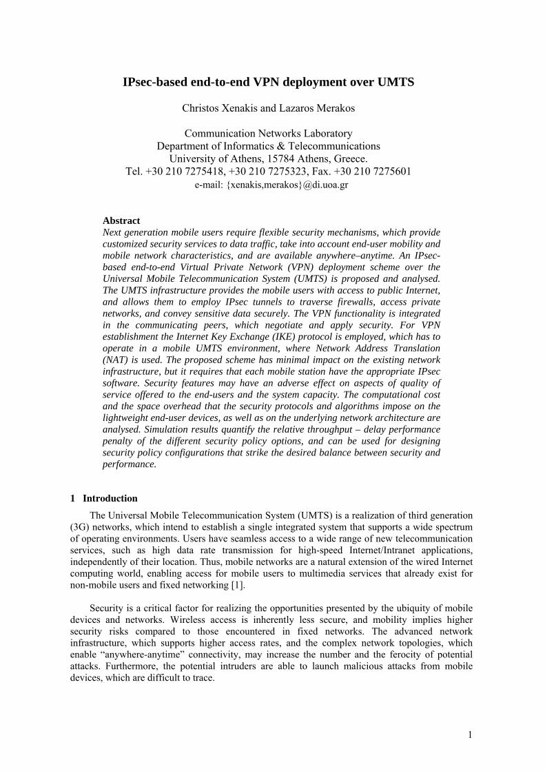
The UMTS network architecture includes the core network (CN), the radio access network and the user equipment, as can be seen in Fig. 1. This division provides the necessary flexibility by allowing the coexistence of different access techniques and different core network technologies, thus, facilitating the migration form 2G to 3G networks. The fundamental difference between the Global System for Mobile communications (GSM) / General Packet Radio Services (GPRS) and the UMTS release ’99 is that the latter supports higher bit rates (up to 2Mbps). This is achieved through a new WCDMA (Wideband Code Division Multiple Access) radio interface for the land-based communications, named UMTS Terrestrial Radio Access Network (UTRAN). The user equipment, which mainly comprises a handheld device with limited processing, memory, and power capabilities, is connected to the UTRAN through the Uu radio interface [1].
Security in 3G-networks requires the consideration of several aspects and issues, such as the wireless access, the end-user mobility, the particular security threats, the type of information to be protected, and the complexity of the network architecture. The 3G-security architecture is built on the security principles of 2G-systems with improvements and enhancements in certain points in order to provide advanced security services. It includes five major security classes: (I) network access security, (II) network domain security, (III) user domain security, (IV) application domain security and (V) visibility and configurability of security. Besides these features, the mobile network operators can apply traditional security technologies used in terrestrial networking to safeguard the UMTS core network, as well as the inter-network communications, such as firewalls, and VPNs [2].
HLR: Home Location RegisterMSC: Mobile Switching CenterSGSN: Serving GPRS Support NodeVLR: Visited Location RegisterRNC: Radio Network ControlerUE: User EquipmentUTRAN: UMTS Terrestrial RadioAccess Network
AuC: Authentication CenterBTS: Base Transceiver StationBSC: Base Station ControllerBSS: Base Station SubsystemCN : Core NetworkEIR: Equipment Identity RegisterGGSN: Gateway GPRS Support Node
Gc
H
lur
lub lubAbis Abis
Um Uu
A luCS Gb luPS
F
CN
UTRANBSS
PSTN
G
E
GpGf
Gi
Gn D
Node BNode B
MSC
VLR
BSC
BTS BTS
RNC RNC
EIR
HLR
GGSNAuC
Gr
SGSN
UE
Fig. 1 : UMTS network architecture
The firewall [13] technology provides a set of mechanisms to enforce a security policy on data from and to a corporate network. They are installed at the borders of the core network permitting traffic originating from specific foreign IP addresses. They attempt to protect the clear-text transmitted data in the UMTS backbone from external attacks, but they are inadequate against attacks that originate from malicious mobile subscribers, as well as from network operator
3
personnel or any other third party who gets access to the UMTS core network. Moreover, mobility may imply roaming between networks and operators, possibly changing the source address, which because of the static configuration of firewalls, may potentially lead to discontinuity of service connectivity for the mobile user.
Since firewalls do not provide privacy and confidentiality, VPNs have to complement them to
protect data in transit. However, VPN services for UMTS subscribers are established in a static manner between the border gateway of the UMTS core network and a remote corporate security gateway failing to provide the necessary flexibility for a mobile user. This makes the realization of VPN services feasible only between the security gateway of a large organization and a mobile operator, when a considerable amount of traffic requires protection. Whenever the static VPN parameters or the VPN topology has to change, the network administrators in both ends must reconfigure it. Furthermore, the aforementioned security scheme can provide VPN service neither to individual mobile users, who may require on demand VPN establishment, nor to enterprise users that may roam internationally.
To satisfy the mobile user requirements, a dynamic, client-initiated security scheme, which enables on demand VPN deployment over the UMTS network architecture is proposed. Security services are based on the IPsec framework, which is widely used in terrestrial networking.
2.2 IPsec-based VPN technology
It is commonly admitted that IPsec [4] is the best security protocol available today. It provides security at the network layer, facilitates the authentication of the communicating entities, and allows a host to set up a secure IP channel with any peer it wishes to connect to. The system selects the security protocols, and determines the algorithms for encryption depending on the level of security required.
IPsec has two security protocols, Authentication Header (AH) and Encapsulating Security Payload (ESP), and supports two types of security algorithms, symmetric encryption algorithms and one-way hash functions. Moreover, it may operate in two modes: transport mode, and tunnel mode. The transport mode provides upper layer protection (transport layer), and applies to pairs of peer hosts. On the other hand, the tunnel mode supports protection via gateway, in which traffic has to pass through to access ultimate destination.
A key concept that appears in the IPsec framework is the Security Association (SA). An SA is a one-way relationship between a sender and a receiver that affords security services. In order to establish an SA between two hosts, they must first agree to apply compatible policy and cryptographic algorithms. They must also share a secure mechanism for determining keying material over an insecure channel. The default IPsec method for secure key negotiation is the IKE [5] protocol. IKE consists of two sequential phases. Phase 1 creates an Internet Security Association and Key Management Protocol (ISAKMP) SA (or IKE SA) that establishes a bi-directional secure channel between the security endpoints. Phase 2 negotiates an IPsec SA using the pre-established secure channel. Multiple IPsec SAs can be established from a single ISAKMP SA, which may be considered as a “control channel” where IKE is the control protocol.
Compared to other security mechanisms, IPsec offers many architectural advantages and remarkable flexibility. The details of network security are usually hidden from applications, which therefore automatically and transparently take advantage of whatever network-layer security services their environment provides. Moreover, IPsec can be transparent to end users eliminating the need to train users on security mechanisms, issue keying material on a per-user basis, or revoke keying material when users leave the organization. A security channel can be configured end-to-end (protecting traffic between two hosts), route-to-route (protecting traffic passing over a
4
particular set of links), or in any other configuration in which network nodes can be identified as appropriate security endpoints. Thus, IPsec can provide security for individual users if needed. This feature is useful for offsite workers, as well as for setting up a secure virtual subnetwork for sensitive applications.
However, there is a concern with regard to the performance of IPsec. When IPsec is considered, the packet size increases due to the IPsec specific headers (ESP, AH, and new IP header for tunnelling) added to each packet. This increases the ratio of header size to payload size reducing the effective bandwidth. Furthermore, the time needed to build such headers and apply the required cryptographic functions to the payload introduces additional delay to packet transmission, especially when the processing capabilities are weak.
2.3 Cryptographic algorithms
IPsec incorporates a wide range of cryptographic algorithms, which transform the original plaintext message into unintelligible ciphertext. The strength of the cipher depends on the choice of block size, key size, and number of rounds. The block size is the amount of data processed each time the cipher kernel is invoked. Larger block size means greater security, but reduced encryption/decryption speed. The key size is the length of the key used to encrypt or decrypt data. Larger key size also means greater security, but may decrease encryption decryption speed. The number of rounds specifies the total number of iterations executed by the cipher kernel loop. Variances in execution times rarely occur for most encryption algorithms since data processing proceeds without case distinctions. The most prominent ciphering algorithms used in the IPsec framework are presented bellow.
Data Encryption Standard (DES) [6] is a symmetric block cipher (shared secret key) with block size fixed at 64 bits. It uses a 64-bit key; however, 8 of these bits are used for odd parity, and, thus, are not counted in the key length. The widely used DES has, on several occasions, been proven to be inadequate for many applications, since specialized hardware has been built that can determine the 56-bit DES key in a few hours. This consideration has signalled that longer keys are necessary.
Triple DES (3DES) is a way of using DES encryption three times. The most common method is to first encrypt the data block with one key. The output of this operation is run through the decryption process with a second key, and the output of that operation is run through the encryption process again with the first key. This process makes the effective key length 112 bits long. The disadvantage of 3DES is that it is about one-third as fast as DES when processing data.
Message Digest (MD5) [7] is a one-way hash function that processes the input text in 512 bit blocks to generate a 128-bit hash value. The algorithm reveals a non-linear behavior as it pads the plaintext to be a multiple of 512 bits block with the last 64 bits of the last block indicating the message length. However, the MD5 function cannot be directly used as a Message Authentication Code (MAC), since it does not rely on secret key. For that reason the combined use with Keyed-Hashing for Message Authentication (HMAC) [8] has been proposed. HMAC is a secret key authentication algorithm, which provides a framework for inserting various hashing algorithms. The combined HMAC-MD5 mechanism provides data origin authentication and integrity protection for Internet security protocols, such as the IPsec.
In the following, based on the security framework described, the deployment of an end-to-end VPN model over the UMTS network is presented. This scheme enhances the mobile user privacy in both the radio path and wireline network segment enabling secure data exchange with a remote site in an ad-hoc fashion.
5
3 IPsec-based VPN deployment
3.1 Network architecture
Consider a mobile subscriber using a mobile station (MS) and attempting to establish a secure remote connection to a corporate Local Area Network (LAN), and access a remote server through the UMTS infrastructure, as shown in Fig. 2. The security gateway (SG) that resides between the LAN and the public Internet functions as a proxy device providing security services to the private network nodes. It is assumed that the Internet and the UMTS backbone are based on IPv4, as well as both the Gateway GPRS Support Node (GGSN) and the SG use NAT [9].
After power-on, the MS looks for a suitable cell in the UTRAN to provide services, and tunes to its control channel. Then, it performs the packet International Mobile Subscriber Identity (IMSI) attach procedure, which creates valid routing information for the packet switched connection in every node involved, as well as transferring the subscriber profile from the Home Location Register (HLR). When the IMSI has been attached, the MS initiates a Packet Data Protocol context activation procedure, which negotiates the desired packet connection characteristics between the MS and the network. The employed protocol for packet switched data transport in the UMTS R99 backbone network is the GPRS Tunneling Protocol. To be able to convey data packets from and to the MS, the Serving GPRS Support Node (SGSN) starts a radio access bearer allocation procedure over UTRAN, and a core network bearer is established between itself and the GGSN [10].
UMTS IP Core
RNC: Radio Network ControllerGGSN: Gateway GPRS Support NodeMS: Mobile StationSGSN: Serving GPRS Support Node
Public Internet
Private LAN
luPS
Remote Access
UM
TS N
etw
ork
MS
RemoteServer
lub
Uu
Node B
RNC
SGSN
GGSN
SecurityGateway
Public Internet
Fig. 2: Network architecture
3.2 VPN establishment
For the end-to-end VPN establishment the IKE [5] protocol is employed. However, its standard IKE version must be enhanced to resolve the problems arising from the NAT presence, and configured to operate in a mobile environment. IKE provides secure key determination via Diffie-Hellman (DH) exchanges [20] with authentication of participants, protection against reply, hijacking, flooding attacks, and negotiation of encryption and/or authentication transforms. The security endpoints exchange DH half-keys (X and Y) to arrive at a mutual session key, k. The key is at least as strong as the strongest half-key, and, thus, neither of the security endpoints can sabotage it.
6
During IKE phase 1, an ISAKMP SA negotiation in aggressive mode (AM) and a NAT
presence detection along path take place. The AM of the IKE key negotiation is an option defined to speed up the IKE transaction at a cost of slightly less security. Moreover, the authentication method used in AM doesn’t involve the IP address of the initiator. Thus, it facilitates the IKE deployment in the UMTS network where dynamic (not static) IP addresses may be used. The authentication of endpoints is based on digital signatures, such as those provided by RSA [21], which use the public key/private key pair technique. In order to prevent “man in the middle” attacks, both MS and SG must authenticate themselves to one another. This is performed by adding an exchange of digitally signed authentication information. Hence, even if an intermediate is able to intercept or read the messages exchanged, it will not be able to forge the signatures.
The NAT presence detection between the security endpoints reveals whether the IP address, or
the related IP port of the transmitted packets is changed along the path. It is performed by sending the hashed values of the IP address and the IP port of each end to the other end. When the hosts calculate those values and get the same result, they know there is no NAT between them. Otherwise, NAT occurs between the security endpoint, and, therefore, a NAT-traversal technique is required to get the IPsec-protected packets [12, 14].
To initiate the IPsec SA negotiation (see Fig. 3), the MS first generates a cookie (CMS) (64-bit random number which facilitates prevention of flooding attacks). Then, the MS chooses a prime number, p, and an integer, g, (referred as DH group), it generates a large random integer, x, and it computes, . In message (1) the MS forwards the CpgX x mod= MS, the DH half-key (X) including the DH group ([g,p]), a nonce (NMS) (a large random number between 64 - 2048 bits that adds randomness), the ISAKMP SA data (ISAMS), and the Identification Data (IDMS) to the SG. The IDMS field contains a certificate of the mobile user, which uniquely identifies him. The ISAMS field includes a series of protection mechanisms and algorithms (e.g., encryption, hash function, etc.) proposed for the ISAKMP SA.
Upon receipt of message (1), the SG validates it. Then, the SG generates a cookie pair (CSG)
and a large random integer, y, and it computes, , as well as the session key resulting
from the DH exchange, . The SG replies with message (2), which contains the cookies, its ISAKMP SA response (ISA
pgY y mod=
pXk y mod=SG), the DH half-key (Y), a nonce (NSG), its certificate
(IDSG), the NAT discovery (NAT-DSG) payload, its authentication information (HASHSG), and the digital signature of the authentication information (SIGSG). The ISASG payload contains the SG response to the security proposal made by the MS in message (1). The HASHSG field used for authentication is computed using the SKEYIDa and the negotiated hash algorithm.
HASHSG = hashfunc(SKEYIDa , Y |1 X | CSG | CMS | ISAMS |IDSG )
SKEYIDa is a key derived from SKEYID and is used as an authentication key. SKEYID is derived differently for each authentication method. Using the digital signature authentication method the SKEYID is computed as follows:
SKEYID=hashfunc( NMS |NSG , k),
SKEYIDa=hashfunc(SKEYID, SKEYIDd |k |CMS |CSG |1 )
SKEYIDd, which is used to derive more keying material, is computed as follows:
1 String concatenation
7
SKEYIDd=hashfunc(SKEYID, k |CMS |CSG |0),
The NAT-DSG payload includes the hashed values of the IP address and the IP port of both
security peers. The first field contains the remote end hash, and the rest contains the local end hash. The hash is calculated as follows:
HASH = hashfunc (CMS | CSG | IP | Port)
The CMS and CSG are included in the hash to make pre-computation attacks for the IP address and IP port impossible [14]. The SG digitally signs its authentication information using its private key (PRVKEYSG) in order to defeat the possibility of man in the middle attack.
SIGSG= PRVKEYSG (HASHSG),
The MS use the SG public key to validate and verify the message. The SG public key is
integrated in the certificate, which is included in message (2). Then, the MS computes the DH key . Finally, with message (3), the MS transmits its authentication information
(HASHpYk x mod=
MS), the digital signature (SIGMS), and the NAT-DMS payload to the SG along with the cookie pair. The HASHMS and the SIGMS are computed as follows:
HASHMS = hashfunc(SKEYIDa , X | Y | CMS | CSG | ISAMS |IDMS )
SIGMS= PRVKEYMS (HASHMS),
where PRVKEYMS is the mobile user private key.
Security GatewayMS
Validate messageCompute k = Yx mod p
Validate IDSG
(1) CMS, ISAMS, X[g,p], NMS, IDMS Generate CSGGenerate yCompute Y = gy mod pValidate IDMS(2) CMS, CSG, ISASG, Y, NSG, IDSG, HASHSG, NAT-DSG , SIGSG
(3) CMS, CSG, HASHMS, NAT-DMS , SIGMS
ISAKMP SA
(4) CMS, CSG, HASH(1), SAMS, NMS, ,IDMS IDSG , NAT-OAMS Validate HASH(1)
GenerateComputeCompute HASH(2)
(5) CMS, CSG, HASH(2), SASG, NSG, ,IDMS, IDSG, NAT-OASG
Validate HASH(2)(6) CMS, CSG, HASH(3)
Validate HASH(3)Compute
IPsec SA
IKE Phase 1
IKE Phase 2
Compute k = Xy mod p
Generate CMSChoose g, p
Generate xCompute X = gx mod p
]p,g[ X ˆˆˆ
p mod gY y ˆˆˆ ˆ= y
Y
p ,g ˆˆChooseGenerate
Compute p mod gX x ˆˆˆ )
= x
p mod Xk y ˆˆˆ ˆ=p mod Yk x ˆˆˆ ˆ=ComputeCompute HASH(3)
Compute HASH(1)
Fig. 3: ISAKMP and IPsec SA negotiation
8
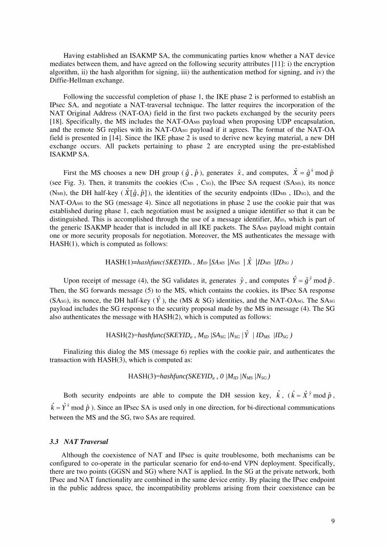
Having established an ISAKMP SA, the communicating parties know whether a NAT device mediates between them, and have agreed on the following security attributes [11]: i) the encryption algorithm, ii) the hash algorithm for signing, iii) the authentication method for signing, and iv) the Diffie-Hellman exchange.
Following the successful completion of phase 1, the IKE phase 2 is performed to establish an IPsec SA, and negotiate a NAT-traversal technique. The latter requires the incorporation of the NAT Original Address (NAT-OA) field in the first two packets exchanged by the security peers [18]. Specifically, the MS includes the NAT-OAMS payload when proposing UDP encapsulation, and the remote SG replies with its NAT-OASG payload if it agrees. The format of the NAT-OA field is presented in [14]. Since the IKE phase 2 is used to derive new keying material, a new DH exchange occurs. All packets pertaining to phase 2 are encrypted using the pre-established ISAKMP SA.
First the MS chooses a new DH group ( , ), generates , and computes, g p x pgX x ˆmodˆˆ )
= (see Fig. 3). Then, it transmits the cookies (CMS , CSG), the IPsec SA request (SAMS), its nonce
(NMS), the DH half-key ( ), the identities of the security endpoints (ID]ˆ,ˆ[ˆ pgX MS , IDSG), and the NAT-OAMS to the SG (message 4). Since all negotiations in phase 2 use the cookie pair that was established during phase 1, each negotiation must be assigned a unique identifier so that it can be distinguished. This is accomplished through the use of a message identifier, MID, which is part of the generic ISAKMP header that is included in all IKE packets. The SAMS payload might contain one or more security proposals for negotiation. Moreover, the MS authenticates the message with HASH(1), which is computed as follows:
HASH(1)=hashfunc(SKEYIDa , MID |SAMS |NMS | X |IDMS |IDSG )
Upon receipt of message (4), the SG validates it, generates , and computes . Then, the SG forwards message (5) to the MS, which contains the cookies, its IPsec SA response
(SA
y pgY y ˆmodˆˆ ˆ=
SG), its nonce, the DH half-key (Y ), the (MS & SG) identities, and the NAT-OAˆ SG. The SASG payload includes the SG response to the security proposal made by the MS in message (4). The SG also authenticates the message with HASH(2), which is computed as follows:
HASH(2)=hashfunc(SKEYIDa , MID |SASG |NSG | Y | IDMS |IDSG )
Finalizing this dialog the MS (message 6) replies with the cookie pair, and authenticates the transaction with HASH(3), which is computed as:
HASH(3)=hashfunc(SKEYIDa , 0 |MID |NMS |NSG )
Both security endpoints are able to compute the DH session key, , ( ,
). Since an IPsec SA is used only in one direction, for bi-directional communications between the MS and the SG, two SAs are required.
k pXk y ˆmodˆˆ ˆ=
pYk x ˆmodˆˆ ˆ=
3.3 NAT Traversal
Although the coexistence of NAT and IPsec is quite troublesome, both mechanisms can be configured to co-operate in the particular scenario for end-to-end VPN deployment. Specifically, there are two points (GGSN and SG) where NAT is applied. In the SG at the private network, both IPsec and NAT functionality are combined in the same device entity. By placing the IPsec endpoint in the public address space, the incompatibility problems arising from their coexistence can be
9
avoided. On the other hand, the NAT at the GGSN takes place between the VPN termination points (MS and SG), and therefore, the incompatibilities presented in [9, 12] should be resolved.
ESP protocol is proposed for VPN services given that it provides confidentiality and integrity protection as well. Unlike AH protocol, the ESP creates a message digest for packet authentication excluding the IP header, and, thus, allows NAT to modify the protected IP packets header without experiencing an IPsec integrity failure. However, the most prominent incompatibility issue that has to be considered in this scenario derives from the coexistence of TCP with NAT. A promising solution to this inconsistency lies on the use of UDP encapsulation. Wrapping the IPsec-protected packets inside a UDP/IP header leaves NAT modifications without acting on the encapsulated packet. The receiver is allowed to discard the UDP header, disregarding also the NAT changes. The only requisite is that both IPsec peers have to support UDP encapsulation/decapsulation functionality.
Finally, concerning the incompatibility between the IKE address identifiers and NAT, the
proposed VPN scenario employs the IKE in aggressive mode, which uses identification data instead of IP addresses for end-node authentication. The same authentication method should also be used during the IPsec SA negotiation.
3.4 VPN Operation
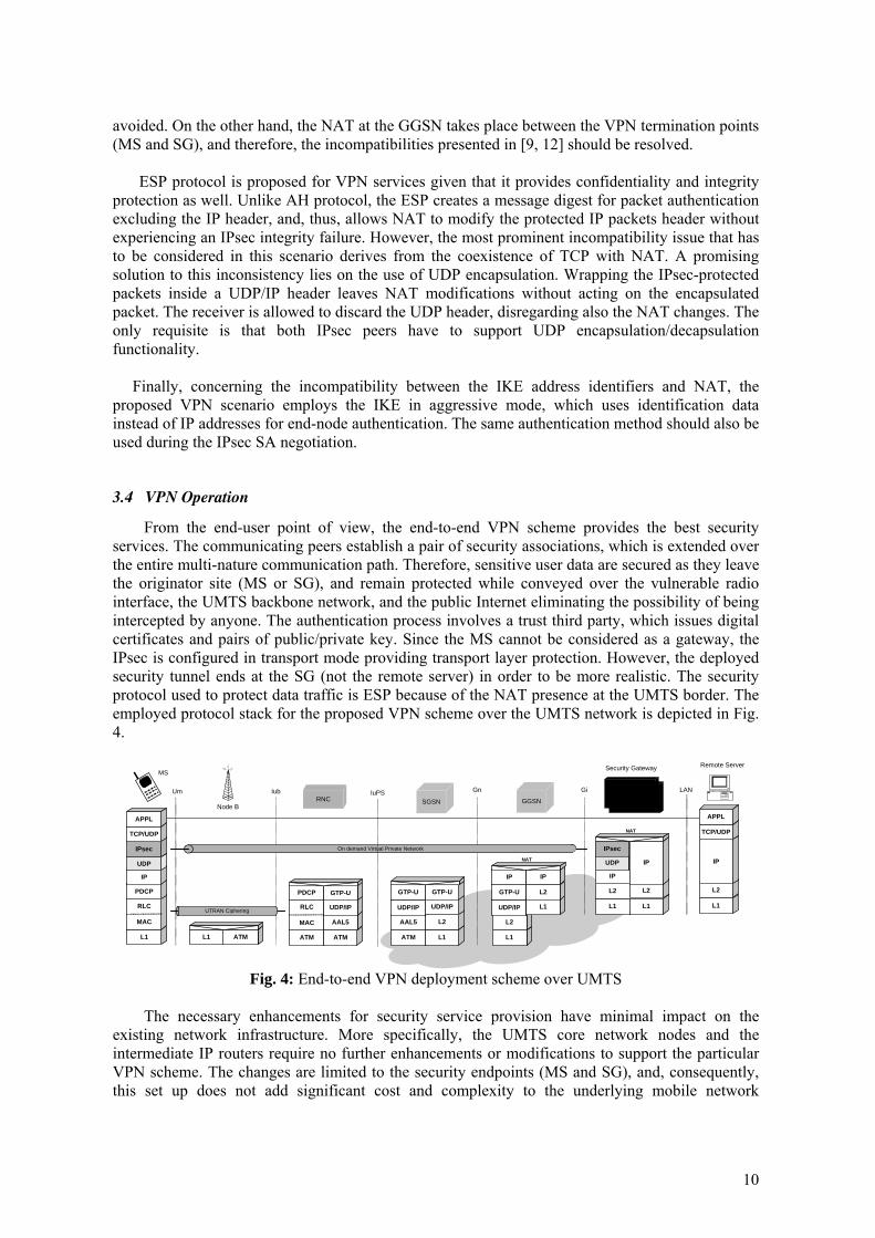
From the end-user point of view, the end-to-end VPN scheme provides the best security services. The communicating peers establish a pair of security associations, which is extended over the entire multi-nature communication path. Therefore, sensitive user data are secured as they leave the originator site (MS or SG), and remain protected while conveyed over the vulnerable radio interface, the UMTS backbone network, and the public Internet eliminating the possibility of being intercepted by anyone. The authentication process involves a trust third party, which issues digital certificates and pairs of public/private key. Since the MS cannot be considered as a gateway, the IPsec is configured in transport mode providing transport layer protection. However, the deployed security tunnel ends at the SG (not the remote server) in order to be more realistic. The security protocol used to protect data traffic is ESP because of the NAT presence at the UMTS border. The employed protocol stack for the proposed VPN scheme over the UMTS network is depicted in Fig. 4.
Remote Server
L1
L2
IP
UDP
L1
RLC
MAC
PDCP
IP
L1 ATM ATM
AAL5
L1
L2
UDP/IP
GTP-U
UDP/IP
GTP-U
L1
L2
UDP/IP
GTP-U
L1
L2
IP IP
L1
L2
IP
On demand Virtual Private Network
L1
L2
IPsec
IP
ATM
RLC
MAC
PDCP
ATM
AAL5
UDP/IP
GTP-U
UDP
IPsec
TCP/UDP
APPL
TCP/UDP
APPL
UTRAN Ciphering
NAT
NAT
MS
Node BSGSN GGSN
Security Gateway
Um Iub IuPS Gn Gi LANRNC
Fig. 4: End-to-end VPN deployment scheme over UMTS
The necessary enhancements for security service provision have minimal impact on the
existing network infrastructure. More specifically, the UMTS core network nodes and the intermediate IP routers require no further enhancements or modifications to support the particular VPN scheme. The changes are limited to the security endpoints (MS and SG), and, consequently, this set up does not add significant cost and complexity to the underlying mobile network
10
infrastructure. However, the end-user devices should incorporate the IPsec functionality including the IKE protocol in order to be able to negotiate and establish security associations.
Whether the MS ensures network connectivity and guarantees the required resources, it is evident that it can establish a VPN, although security features may reduce the system availability. VPN provision is restricted by the terminal processing power, and the access and core network capacity. Thus, the VPN model reliability and scalability correspond to the mobile network reliability and scalability.
A VPN over a mobile network should consider end-user mobility. The proposed end-to-end
VPN is extended between the communicating peers operating just over the network layer. Therefore, this scheme has no interrelation with the provided network connectivity and operation, as far it concerns the UMTS technology. The mobile operator does not even realize the existence of a VPN, and, thus, no service level agreement is required. Since the security parameters, which are contained in the IPsec SA, are not affected by the UMTS mobility management procedures, the deployed scheme supports user mobility and operates transparent to the MS movement.
4. Performance analysis
While the benefits of deploying IPsec-based end-to-end VPN over the UMTS to solve network security problems have been adequately analysed, the communication overhead that this security mechanism introduces to the involved parties has to be considered. Data protection increases the required bandwidth, and security transformation reduces the performance, and delays data processing and transmission. Moreover, since UMTS employs an optimised ciphering for packet data transmission over the radio interface, the proposed security scheme duplicates encryption (packet encapsulation) over the expensive radio interface, which increases the communication cost and decreases the overall access network capacity. Quantifying the security overhead makes mobile users and mobile network operators aware of the price of the added security features, and assists them in making optimised security policy configurations. For the reader’s convenience, Table 1 gives the notations and definitions used in the analysis that follows. Symbol Description
AuTESP Authentication data field size for ESP (bytes) HESP , HIP , HTCP , HUDP The header size of ESP, IP, TCP and UDP protocols (bytes) K The size of the extra appended inner form of the key in MD5 (512 bits) Key An arbitrary size secret key shared by the sender and receiver (bits) Ki , Ko Extended forms (512-bit) of the input Key nk The number of input blocks for the inner MD5 R(Sd ) The ratio of the actual payload over the total packet length, as a function of the original IP
packet size using Null+MD5, DES, DES+MD5, 3DES, 3DES+MD5 security services Sd The size of the original IP message (bytes) sp The size of the padding field in MD5 (bits) ss The size of the field that presents the message length in MD5 (bits) S(Sd ) The size of IPsec-protected packets as a function of the original IP packet size using
Null+MD5, DES, DES+MD5, 3DES, 3DES+MD5 security services (bytes) THMAC-MD5(nk) The total number of operations required to apply HMAC-MD5, as a function of the
number of input blocks (512 bits) TDES , T3DES The total number of operations per 64-bit block for DES and 3DES encryption tDES(Sd , CP) , t3DES(Sd , CP) The time required for DES and 3DES encryption (decryption) of a message size Sd , given
a processor with capability CP Millions Instruction Per Second (MIPS) TMD5 The total number of operations per 512-bit block for the MD5 algorithm
11
TrESP ESP trailer size (bytes) UDES(Sd ) , U3DES(Sd ) The number of operations required for DES and 3DES encryption (decryption) as a
function of the message size Sd . UHMAC-MD5(Sd ) The number of operations required for applying combined HMAC-MD5 as a function of
the message size Sd
Table 1: Notations definition
4.1 Computational cost
The IPsec functionality imposes an additional computational cost. This cost is associated with the memory needed for IPsec code and with data structures, and the computation of the integrity check values (ICV), encryption and decryption, which is added in a per-packet fashion. Therefore, the deployment and operation of IP security functionality in UMTS handheld devices, which are characterized by limited processing and energy power, may increase significantly the processing latency and result in service inadequacy.
In the proposed scheme, transport mode ESP is used to encrypt and optionally authenticate the
data carried by IP (e.g., a TCP segment). The execution time of encryption and authentication algorithms is a function of the size of input packet as well as the processor capabilities, and is independent of the statistical characteristics of data.
The DES ciphering uses a 56-bit key, and block sizes of 64 bits. Since DES is a Feistel cipher, the encryption speed of DES is equivalent to the decryption speed of DES. 3DES is the chained form of DES, and, thus, it is assumed to have three times the number of operations of DES. As presented in [15], the number of operations per 64-bit block for DES, TDES , is 2697 operations, and for 3DES, T3DES , is 8091. The number of operations required by a processor to perform DES, UDES(Sd,) and 3DES, U3DES(Sd,), as a function of the packet size Sd, are
( ) (1) T SSU DESd
dDES ×⎥⎥⎤
⎢⎢⎡ ×
=64
8 , ( ) )( T SSU DESd
dDES 264
833 ×⎥⎥
⎤⎢⎢⎡ ×
=
where ⎡x⎤ means the smallest integer larger than, or equal to x. Given a processor which can
perform CP Millions Instruction Per Second (MIPS), the required encryption (decryption) times for DES, tDES (Sd, CP), and 3DES, t3DES (Sd, CP), are
( ) )( C
T SC StP
DESdPdDES 3
648, ×⎥⎥
⎤⎢⎢⎡ ×
= , ( ) )( C
T SC StP
DESdPdDES 4
648, 3
3 ×⎥⎥⎤
⎢⎢⎡ ×
=
Hash computation and hash verification are equivalent operations, and, thus, they consume the
same amount of time. A common MAC algorithm used in IPsec is the combined HMAC-MD5. The first step in the MD5 algorithm is padding the original message for its size to become a multiple of 512 bits with the last 64 bits of the last block indicating the length of the message. Then, the algorithm produces the message digest. Although MD5 produces a 128-bit hash value, for IPsec authentication only a truncated 96 bit hash value is used. The total number of operations, TMD5 , is 720 plus 24 operations per block for initialization and termination [15].
The combined HMAC-MD5 algorithm is formulated as follows:
MD5(Ko, MD5(K i , Text)) where
Ki = Key ⊕ ipad
12
Ko = Key ⊕ opad
Ki and Ko are two extended forms (512-bit) of the input Key, and are generated by “exclusive
or” the Key with ipad the inner padding (512 bits), and opad the outer padding (512 bits) respectively. Key is an arbitrary size secret key shared by the sender and receiver, and ⊕ is the XOR operation.
For an input text of size Sd bytes, the number of input blocks for the inner MD5, nk , is
)( KssS
n spdk 5
5128
⎟⎟⎠
⎞⎜⎜⎝
⎛ +++×=
where sp is the size (in bits) of the padding field, ss is the size (in bits) of the field that specifies
the message length, and K is the size (in bits) of the extra appended inner form of the key.
In the outer MD5, the output of the inner MD5 (128-bit digest) is appended to Ko . According to MD5, this is padded to two 512-bit blocks. Thus, the total number of operations in applying combined HMAC-MD5, THMAC-MD5(nk), and, UHMAC-MD5(Sd ), as a function of the number of input blocks nk, and the packet size Sd , are
THMAC-MD5 (nk) = 32 + (2 + nk )× 744 (6)
( ) ( ) )( S 744 SU ddMDHMAC 7
512648
5 ⎟⎟⎠
⎞⎜⎜⎝
⎛ ⎥⎥
⎤⎢⎢⎡ +×
×+ 2264 =−
Finally, the required authentication and verification time for HMAC-MD5, tHMAC-MD5 (nk ,CP),
as a function of the number of input blocks and the processor capabilities, is
( ) ( ) )( C
744n232C ntP
kPkMDHMAC 8,5
×++=−
Based on the formulas (1), (2), and (7), the total number of operations required by a processor
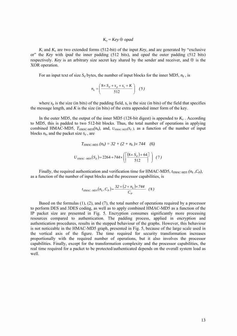
to perform DES and 3DES coding, as well as to apply combined HMAC-MD5 as a function of the IP packet size are presented in Fig. 5. Encryption consumes significantly more processing resources compared to authentication. The padding process, applied in encryption and authentication procedures, results in the stepped behaviour of the graphs. However, this behaviour is not noticeable in the HMAC-MD5 graph, presented in Fig. 5, because of the large scale used in the vertical axis of the figure. The time required for security transformation increases proportionally with the required number of operations, but it also involves the processor capabilities. Finally, except for the transformation complexity and the processor capabilities, the real time required for a packet to be protected/authenticated depends on the overall system load as well.
13
0 250 500 7500,0
2,0x10⁵
4,0x10⁵
6,0x10⁵
8,0x10⁵
3DES DES HMAC-MD5
Num
ber o
f ope
ratio
ns
Original IP packet size (bytes)
Fig. 5: The number of operations required to perform 3DES, DES, and
HMAC-MD5 as a function of the packet size.
4.2 Space overhead
Ciphering, IPsec formation, and UDP encapsulation, applied in the mobile VPN scenario, increase the packet size, and, therefore, create overhead. Cryptographic algorithm overhead is created by padding the original message to reach the desired size prior to algorithmic processing. The security overhead is related to the IPsec mode of operation, as well as the security services provided. In case IPsec is configured in tunnel mode, the entire IP packet, including the IP header, is protected, and an additional IP encapsulation is carried out. On the other hand, the transport mode, used in the proposed security scheme, protects only the IP packet’s payload minimizing the operating cost.
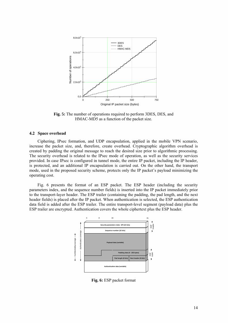
Fig. 6 presents the format of an ESP packet. The ESP header (including the security parameters index, and the sequence number fields) is inserted into the IP packet immediately prior to the transport-layer header. The ESP trailer (containing the padding, the pad length, and the next header fields) is placed after the IP packet. When authentication is selected, the ESP authentication data field is added after the ESP trailer. The entire transport-level segment (payload data) plus the ESP trailer are encrypted. Authentication covers the whole ciphertext plus the ESP header.
Authentication data (variable)
Pad length (8 bits) Next header (8 bits)
Payload data (variable)
Sequence number (32 bits)
Security parameters index SPI (32 bits)
0 8 16 31
Auth
entic
atio
n co
vera
ge
Con
fiden
tialit
ycov
erag
e
ESP
head
er
ESP
traile
rPadding data (0 - 255 bytes)
Fig. 6: ESP packet format
14
The ESP protocol overhead is 10 bytes (fixed size fields) plus the variable size padding and authentication data fields. The Authentication data field is algorithm and packet specific. The HMAC-MD5 algorithm generates a truncated ICV of 96 bits (12 bytes) to conform to the IPsec ESP authentication data size. The padding field expands the ciphertext (consisting of the payload data, padding, pad length, and next header fields) to be a multiple of the encryption algorithm block size (64-bits for DES). Moreover, the padding field is used to assure that the ciphertext is an integer multiple of 32 bits. Thus, the total overhead needed for each ESP-protected packet through a security association in transport mode is 22 bytes plus the variable size padding field.
Besides ESP, UDP encapsulation for NAT traversal also increases the protected packet size. UDP implements a fairly "lightweight" layer abstracting network traffic in the form of datagrams. A datagram comprises one single unit of binary data; the first eight (8) bytes of a datagram contain the header information, and the remaining bytes contain the data itself.
ESPauth
Payload TCPhdr
0 64 96
Orig IPhdr
ESPtrl Payload TCP
hdrESPhdr
UDPhdr
Orig IPhdr
ESPtrl Payload TCP
hdrESPhdr
UDPhdr
Orig IPhdr
84
IP traffic
DES or3EDS
Null + MD5 orDES + MD5 or3DES + MD5
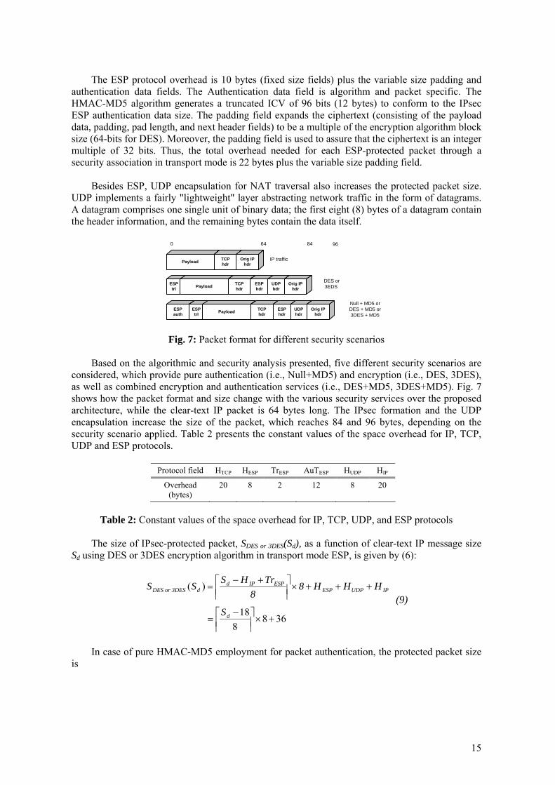
Fig. 7: Packet format for different security scenarios
Based on the algorithmic and security analysis presented, five different security scenarios are
considered, which provide pure authentication (i.e., Null+MD5) and encryption (i.e., DES, 3DES), as well as combined encryption and authentication services (i.e., DES+MD5, 3DES+MD5). Fig. 7 shows how the packet format and size change with the various security services over the proposed architecture, while the clear-text IP packet is 64 bytes long. The IPsec formation and the UDP encapsulation increase the size of the packet, which reaches 84 and 96 bytes, depending on the security scenario applied. Table 2 presents the constant values of the space overhead for IP, TCP, UDP and ESP protocols.
Protocol field HTCP HESP TrESP AuTESP HUDP HIP
Overhead (bytes)
20 8 2 12 8 20
Table 2: Constant values of the space overhead for IP, TCP, UDP, and ESP protocols
The size of IPsec-protected packet, SDES or 3DES(Sd), as a function of clear-text IP message size
Sd using DES or 3DES encryption algorithm in transport mode ESP, is given by (6):
3688
18
)(
+×⎥⎥⎤
⎢⎢⎡ −
=
+++×⎥⎥⎤
⎢⎢⎡ +−
=
d
IPUDPESPESPIPd
dSDES or 3DE
S
HHH88
TrHSSS (9)
In case of pure HMAC-MD5 employment for packet authentication, the protected packet size
is
15
4844
18
)(
+×⎥⎥⎤
⎢⎢⎡ −
=
++++×⎥⎥⎤
⎢⎢⎡ +−
= +
d
ESPIPUDPESPESPIPd
dMD5Null
S
AuTHHH44
TrHSSS (10)
Finally, for the combined DES+MD5 and 3DES+MD5 security scenarios, which support both
data encryption and authentication, the protected packet size is given by (11):
4888
18
88
)(5
+×⎥⎥⎤
⎢⎢⎡ −
=
++++×⎥⎥⎤
⎢⎢⎡ +−
=++
d
ESPIPUDPESPESPIPd
d MD5 or 3DES MDDES
S
AuTHHHTrHSSS (11)
The application of security decreases the ratio between the actual payload and the total packet
length, and, therefore, increases “wasted” bandwidth (i.e., bandwidth that does not carry actual data). The ratio R(Sd), as a function of original IP packet size Sd, for the aforementioned set of data security services, is as follows:
)( d
TCPIPdd SS
HHS)R(S −−= (12)
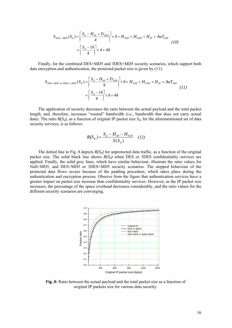
The dotted line in Fig. 8 depicts R(Sd) for unprotected data traffic, as a function of the original
packet size. The solid black line shows R(Sd) when DES or 3DES confidentiality services are applied. Finally, the solid grey lines, which have similar behaviour, illustrate the ratio values for Null+MD5, and DES+MD5 or 3DES+MD5 security scenarios. The stepped behaviour of the protected data flows occurs because of the padding procedure, which takes place during the authentication and encryption process. Observe from the figure that authentication services have a greater impact on packet size increase than confidentiality services. However, as the IP packet size increases, the percentage of the space overhead decreases considerably, and the ratio values for the different security scenarios are converging.
300 600 900 1200 15000,0
0,1
0,2
0,3
0,4
0,5
0,6
0,7
0,8
0,9
1,0
Original IP DES or 3DES Null +MD5 DES+MD5 or 3DES+MD5
Pac
ket r
atio
Original IP packet size (bytes)
Fig. 8: Ratio between the actual payload and the total packet size as a function of
original IP packets size for various data security.
16
The multiple encapsulation of the original IP packet induces a waste of valuable resources, and may cause network efficiency problems, and performance degradation. It is anticipated that the increased bandwidth demand will not noticeably affect the fixed network infrastructure, but it will have a greater impact on the scarce radio bandwidth. The packet size increase has negative effects not only on bandwidth usage, but also on the transmission delay, router internal delays, queuing delay, and, thus, the overall packet delay. The transmission delay increases proportionally with the packet size. Queuing delay is also sensitive to packet size, and this is evident with low bandwidth links, such as the UMTS radio network segment.
Summarizing it can be figured that the processing time for packet encryption is greater than the time required for packet authentication. This difference is becoming more noticeable in the UMTS network, where the processing capabilities of the mobile devices are limited. However, the space overhead for ESP confidentiality is smaller compared to the ESP authentication overhead. In case security protection is packet oriented, the packet size should be maximized to increase the network speed. Nevertheless, whilst the IP packet size becomes larger, the end-to-end system throughput degrades, especially when the resources limited UMTS radio network is involved.
The analysed model, except for the UDP encapsulation for NAT traversal, pertains to the
IPsec deployment model. Thus, eliminating the extra UDP encapsulation overhead, the aforementioned performance analysis describes the IPsec deployment and operation. In the next section, a performance study of the proposed end-to-end VPN scheme over the UMTS network takes place using a simulation model.
4.3 Simulation model and results
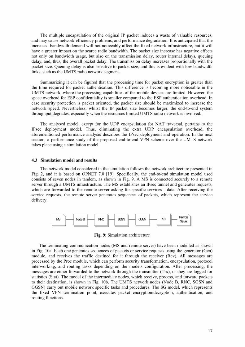
The network model considered in the simulation follows the network architecture presented in Fig. 2, and it is based on OPNET 7.0 [19]. Specifically, the end-to-end simulation model used consists of seven nodes in tandem, as shown in Fig. 9. A MS is connected securely to a remote server through a UMTS infrastructure. The MS establishes an IPsec tunnel and generates requests, which are forwarded to the remote server asking for specific services - data. After receiving the service requests, the remote server generates sequences of packets, which represent the service delivery.
MS Node B RNC SGSN GGSN SG RemoteServer
Fig. 9: Simulation architecture
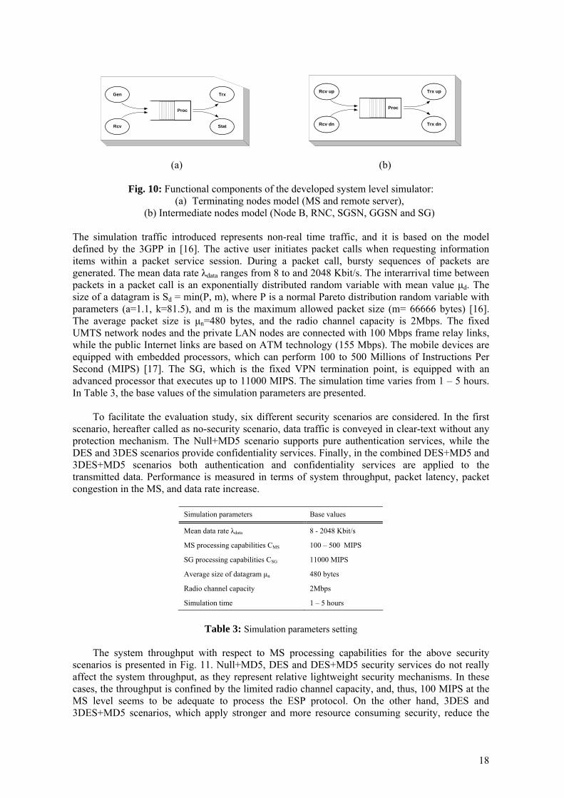
The terminating communication nodes (MS and remote server) have been modelled as shown in Fig. 10a. Each one generates sequences of packets or service requests using the generator (Gen) module, and receives the traffic destined for it through the receiver (Rcv). All messages are processed by the Proc module, which can perform security transformation, encapsulation, protocol interworking, and routing tasks depending on the models configuration. After processing, the messages are either forwarded to the network through the transmitter (Trx), or they are logged for statistics (Stat). The model of the intermediate nodes, which receive, process, and forward packets to their destination, is shown in Fig. 10b. The UMTS network nodes (Node B, RNC, SGSN and GGSN) carry out mobile network specific tasks and procedures. The SG model, which represents the fixed VPN termination point, executes packet encryption/decryption, authentication, and routing functions.
17
Gen
Rcv
Proc
Trx
Stat
Rcv up
Rcv dn
Proc
Trx up
Trx dn
(a)
(b)
Fig. 10: Functional components of the developed system level simulator: (a) Terminating nodes model (MS and remote server),
(b) Intermediate nodes model (Node B, RNC, SGSN, GGSN and SG) The simulation traffic introduced represents non-real time traffic, and it is based on the model defined by the 3GPP in [16]. The active user initiates packet calls when requesting information items within a packet service session. During a packet call, bursty sequences of packets are generated. The mean data rate λdata ranges from 8 to and 2048 Kbit/s. The interarrival time between packets in a packet call is an exponentially distributed random variable with mean value μd. The size of a datagram is Sd = min(P, m), where P is a normal Pareto distribution random variable with parameters (a=1.1, k=81.5), and m is the maximum allowed packet size (m= 66666 bytes) [16]. The average packet size is μn=480 bytes, and the radio channel capacity is 2Mbps. The fixed UMTS network nodes and the private LAN nodes are connected with 100 Mbps frame relay links, while the public Internet links are based on ATM technology (155 Mbps). The mobile devices are equipped with embedded processors, which can perform 100 to 500 Millions of Instructions Per Second (MIPS) [17]. The SG, which is the fixed VPN termination point, is equipped with an advanced processor that executes up to 11000 MIPS. The simulation time varies from 1 – 5 hours. In Table 3, the base values of the simulation parameters are presented.
To facilitate the evaluation study, six different security scenarios are considered. In the first scenario, hereafter called as no-security scenario, data traffic is conveyed in clear-text without any protection mechanism. The Null+MD5 scenario supports pure authentication services, while the DES and 3DES scenarios provide confidentiality services. Finally, in the combined DES+MD5 and 3DES+MD5 scenarios both authentication and confidentiality services are applied to the transmitted data. Performance is measured in terms of system throughput, packet latency, packet congestion in the MS, and data rate increase.
Simulation parameters Base values
Mean data rate λdata 8 - 2048 Kbit/s
MS processing capabilities CMS 100 – 500 MIPS
SG processing capabilities CSG 11000 MIPS
Average size of datagram μn 480 bytes
Radio channel capacity 2Mbps
Simulation time 1 – 5 hours
Table 3: Simulation parameters setting
The system throughput with respect to MS processing capabilities for the above security
scenarios is presented in Fig. 11. Null+MD5, DES and DES+MD5 security services do not really affect the system throughput, as they represent relative lightweight security mechanisms. In these cases, the throughput is confined by the limited radio channel capacity, and, thus, 100 MIPS at the MS level seems to be adequate to process the ESP protocol. On the other hand, 3DES and 3DES+MD5 scenarios, which apply stronger and more resource consuming security, reduce the
18
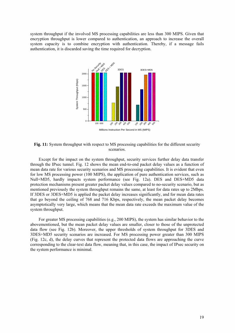
system throughput if the involved MS processing capabilities are less than 300 MIPS. Given that encryption throughput is lower compared to authentication, an approach to increase the overall system capacity is to combine encryption with authentication. Thereby, if a message fails authentication, it is discarded saving the time required for decryption.
0
0
500
1000
1500
2000S
yste
m T
hrou
ghpu
t (K
bps)
3DES+MD5DES + MD5
DESNull
+ MD5
No Sec
urity
3DES
500
40030
020
010
0100 -50010
020
030
040
0 500
Millions Instruction Per Second in MS (MIPS)
Fig. 11: System throughput with respect to MS processing capabilities for the different security
scenarios.
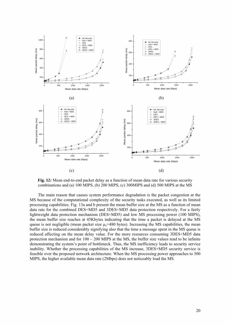
Except for the impact on the system throughput, security services further delay data transfer through the IPsec tunnel. Fig. 12 shows the mean end-to-end packet delay values as a function of mean data rate for various security scenarios and MS processing capabilities. It is evident that even for low MS processing power (100 MIPS), the application of pure authentication services, such as Null+MD5, hardly impacts system performance (see Fig. 12a). DES and DES+MD5 data protection mechanisms present greater packet delay values compared to no-security scenario, but as mentioned previously the system throughput remains the same, at least for data rates up to 2Mbps. If 3DES or 3DES+MD5 is applied the packet delay increases significantly, and for mean data rates that go beyond the ceiling of 768 and 716 Kbps, respectively, the mean packet delay becomes asymptotically very large, which means that the mean data rate exceeds the maximum value of the system throughput.
For greater MS processing capabilities (e.g., 200 MIPS), the system has similar behavior to the abovementioned, but the mean packet delay values are smaller, closer to those of the unprotected data flow (see Fig. 12b). Moreover, the upper thresholds of system throughput for 3DES and 3DES+MD5 security scenarios are increased. For MS processing power greater than 300 MIPS (Fig. 12c, d), the delay curves that represent the protected data flows are approaching the curve corresponding to the clear-text data flow, meaning that, in this case, the impact of IPsec security on the system performance is minimal.
19
0 500 1000 1500 2000
200
400
600
800
1000
Mea
n pa
cket
del
ay (m
s)
Mean data rate (kbps)
No Security Null + MD5 DES DES + MD5 3DES 3DES + MD5
0 500 1000 1500 2000
200
400
600
800
Mea
n pa
cket
del
ay (m
s)
Mean data rate (kbps)
No Security Null + MD5 DES DES + MD5 3DES 3DES + MD5
(a) (b)
0 500 1000 1500 2000
200
400
600
800
Mea
n pa
cket
del
ay (m
s)
Mean data rate (kbps)
No Security Null + MD5 DES DES + MD5 3DES 3DES + MD5
0 500 1000 1500 2000
200
400
600
800
Mea
n pa
cket
del
ay (m
s)
Mean data rate (kbps)
No Security Null + MD5 DES DES + MD5 3DES 3DES + MD5
(c) (d)
Fig. 12: Mean end-to-end packet delay as a function of mean data rate for various security combinations and (a) 100 MIPS, (b) 200 MIPS, (c) 300MIPS and (d) 500 MIPS at the MS
The main reason that causes system performance degradation is the packet congestion at the
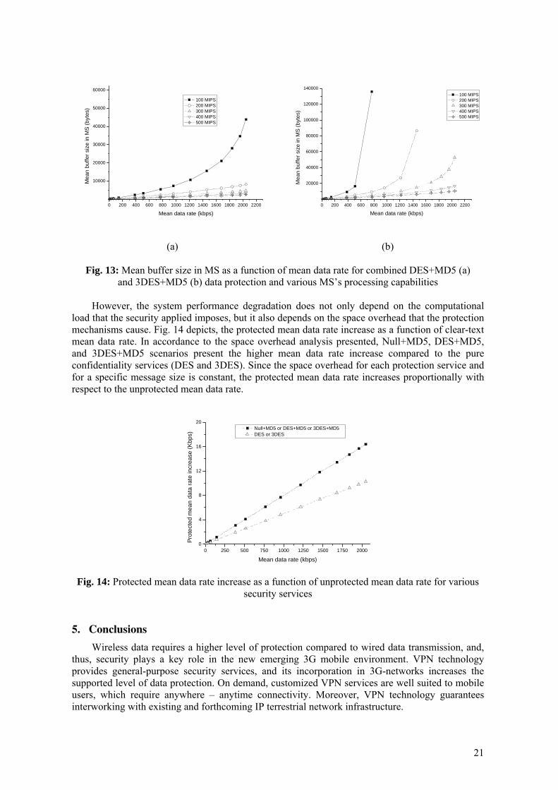
MS because of the computational complexity of the security tasks executed, as well as its limited processing capabilities. Fig. 13a and b present the mean buffer size at the MS as a function of mean data rate for the combined DES+MD5 and 3DES+MD5 data protection respectively. For a fairly lightweight data protection mechanism (DES+MD5) and low MS processing power (100 MIPS), the mean buffer size reaches at 45Kbytes indicating that the time a packet is delayed at the MS queue is not negligible (mean packet size μn=480 bytes). Increasing the MS capabilities, the mean buffer size is reduced considerably signifying also that the time a message spent in the MS queue is reduced affecting on the mean delay value. For the more resources consuming 3DES+MD5 data protection mechanism and for 100 – 200 MIPS at the MS, the buffer size values tend to be infinite demonstrating the system’s point of bottleneck. Thus, the MS inefficiency leads to security service inability. Whether the processing capabilities of the MS increase, 3DES+MD5 security service is feasible over the proposed network architecture. When the MS processing power approaches to 500 MIPS, the higher available mean data rate (2Mbps) does not noticeably load the MS.
20
0 200 400 600 800 1000 1200 1400 1600 1800 2000 2200
10000
20000
30000
40000
50000
60000M
ean
buffe
r siz
e in
MS
(byt
es)
Mean data rate (kbps)
100 MIPS 200 MIPS 300 MIPS 400 MIPS 500 MIPS
0 200 400 600 800 1000 1200 1400 1600 1800 2000 2200
20000
40000
60000
80000
100000
120000
140000
Mea
n bu
ffer s
ize
in M
S (b
ytes
)
Mean data rate (kbps)
100 MIPS 200 MIPS 300 MIPS 400 MIPS 500 MIPS
(a) (b)
Fig. 13: Mean buffer size in MS as a function of mean data rate for combined DES+MD5 (a) and 3DES+MD5 (b) data protection and various MS’s processing capabilities
However, the system performance degradation does not only depend on the computational
load that the security applied imposes, but it also depends on the space overhead that the protection mechanisms cause. Fig. 14 depicts, the protected mean data rate increase as a function of clear-text mean data rate. In accordance to the space overhead analysis presented, Null+MD5, DES+MD5, and 3DES+MD5 scenarios present the higher mean data rate increase compared to the pure confidentiality services (DES and 3DES). Since the space overhead for each protection service and for a specific message size is constant, the protected mean data rate increases proportionally with respect to the unprotected mean data rate.
0 250 500 750 1000 1250 1500 1750 20000
4
8
12
16
20 Null+MD5 or DES+MD5 or 3DES+MD5 DES or 3DES
Pro
tect
ed m
ean
data
rate
incr
ease
(Kbp
s)
Mean data rate (kbps)
Fig. 14: Protected mean data rate increase as a function of unprotected mean data rate for various
security services
5. Conclusions
Wireless data requires a higher level of protection compared to wired data transmission, and, thus, security plays a key role in the new emerging 3G mobile environment. VPN technology provides general-purpose security services, and its incorporation in 3G-networks increases the supported level of data protection. On demand, customized VPN services are well suited to mobile users, which require anywhere – anytime connectivity. Moreover, VPN technology guarantees interworking with existing and forthcoming IP terrestrial network infrastructure.
21
In this paper, an IPsec-based end-to-end VPN deployment scheme over the UMTS has been
proposed and analysed. The UMTS infrastructure provides the mobile users with access to the public Internet, and allows them to employ IPsec tunnels to traverse firewalls, access private networks, and convey sensitive data securely. The proposed scheme has minimal impact on the existing network infrastructure, but it requires that mobile stations have the appropriate software (IPsec) in order to apply the required security policy.
Security features may have an adverse impact on aspects of quality of service offered to the end-users and the system capacity. Data protection increases the required bandwidth, and security transformations reduce the performance in terms of throughput and delay. The computational cost and the space overhead that the security protocols and algorithms impose on the lightweight end-user devices, as well as on the underlying network architecture have been analysed.
Encryption consumes significantly more processing resources compared to authentication.
Similarly, the processing time for packet encryption is greater than the time required for packet authentication. On the other hand, the space overhead for ESP confidentiality is smaller compared to the ESP authentication overhead. The time required for security transformation increases proportionally with the required number of operations, but it also involves the processor capabilities. However, except for the transformation complexity and the processor capabilities, the real time required for a packet to be protected/authenticated depends on the overall system load.
End-to-end security, which applies authentication and encryption services on the entire
volume of data transferred in a wireless resources constrained environment, such as the UMTS, arises some concerns from the performance point of view. The obtained simulation results have determined that the proposed security model is feasible for MS processing capabilities that exceed 300 MIPS and for mean packet size greater than 480 bytes. Otherwise, the UMTS terminal becomes a performance bottleneck, and the effective system throughput is reduced.
Clearly, there is a need to carefully choose the proper configuration of IPsec that is well suited
for the application of interest. By trading off security with throughput – delay performance, a system engineer can work out a solution that balances the system real-time requirements. In order to avoid unnecessary overhead, security policy guidelines need to be developed that prescribes the appropriate type of protection for the different information flow types. The obtained simulation results have quantified the relative throughput – delay performance penalty of the different security policy option, and can be used for designing security policy configurations that strike the desired balance between security and performance.
Acknowledgments
The authors would like to thank Nikos Loukas and the anonymous reviewers for their comments and suggestions.
References
[1] 3GPP TS 23.002 (v3.6.0 ) “Network Architecture”, release ’99, Sept 2002. [2] C. Xenakis and L. Merakos, “Security in third Generation Mobile Networks,” Computer
Communications, Vol. 27, No. 7, May 2004, pp. 638-650. [3] B. Gleeson, A. Lin, J. Heinanen, G. Armitage, and A. Malis, “A Framework for IP Based Virtual
Private Networks,” RFC 2764, Feb. 2000. [4] S. Kent and R. Atkinson, “Security Architecture for the Internet Protocol,” RFC 2401, Nov. 1998. [5] D. Harkins and D. Carrel, “The Internet Key Exchange (IKE),” RFC 2409, Nov. 1998.
22
[6] US National Bureau of Standards, “Data Encryption Standard,” Federal Information Processing Standard (FIPS) publication 46-2, Dec. 1993, http://www.itl.nist.gov/fipspubs/fip46-2.htm
[7] R. Rivest, “The MD5 Message-Digest Algorithm,” RFC1321, Apr 1992. [8] C. Madson, and R. Glenn, “The Use of HMAC-MD5-96 within ESP and AH,” RFC 2403, Nov. 1998. [9] L. Phifer, “The Trouble with NAT,” Cisco The Internet Protocol Journal, vol. 3, no. 4, Dec. 2000, pp 2-
13. [10] 3GPP TS 24.008 (v3.15.0 ) “Mobile Radio Interface Layer 3 specification; Core Network Protocols –
Stage 3”, release ’99, March 2003. [11] C. Xenakis, E. Gazis and L. Merakos, “Secure VPN Deployment in GPRS Mobile Network,” Proc.
European Wireless 2002, Florence Italy, Feb. 2002, pp. 293-300. [12] C. Xenakis and L. Merakos, “On Demand Network-wide VPN Deployment in GPRS,” IEEE Network,
Vol. 16, No. 6, Nov/Dec. 2002, pp. 28-37. [13] R. Hunt and T. Verwoerd, “Reactive firewalls – a new technique,” Computer Communications, Vol. 26,
No. 12, July. 2003, pp. 1302-1317. [14] T. Kivinen et al., “Negotiation of NAT-Traversal in the IKE,” draft-ietf-ipsec-t-ike-00.txt, Internet
Draft, June 2001. [15] O. Elkeelany et. all, “Performance Analysis of IPSec Protocol: Encryption and Authentication,” IEEE
Communications Conference (ICC 2002), pp. 1164-1168, 2002. [16] ETSI,Universal Mobile Telecommunication System (UMTS);Selection Procedures for the Choice of
Radio Transmission Technologies of the UMTS, Technical Report TR 101 112 v3.2.0,1998. [17] ARM microprocessor solutions from ARM Ltd, http://www.arm.com/products/CPUs [18] A. Huttunen et al., “UDP Encapsulation of IPsec Packets,” draft-ietf-ipsec-udp-encaps-01.txt, Internet
Draft, Oct. 2001. [19] OPNET Technologies Inc., http://www.mil3.com/opnet/home.html [20] W. Diffie and M. E. Hellman, “New Directions in Cryptography,” IEEE Trans. Info. Theory, vol. 22,
Nov. 1976, pp. 644–54. [21] R. Rivest, A. Shamir, and L. M. Adleman, “A Method for Obtaining Digital Signatures and Public-Key
Cryptosystems,” Commun. ACM, vol. 21, Feb. 1978, pp. 120–26.
Biographies
Christos Xenakis ([email protected]) received his B.Sc degree in computer science in 1993 and M.Sc degree in telecommunication and computer networks in 1996, both from the Department of Informatics and Telecommunications, University of Athens, Greece. From 1998 – 2000 was with the Greek telecoms system development firm Teletel S.A., where was involved in the design and development of advanced telecommunications subsystems for ISDN, ATM, GSM, and GPRS. Since 1996 he has been a member of the Communication Networks Laboratory of the University of Athens. He has participated in numerous projects realized in the context of EU Programs (ACTS, ESPRIT, IST). His research interests are in the field of mobile/ wireless networks, security and distributed network management. He is the author of over 15 papers in the above areas. Lazaros Merakos ([email protected]) received the Diploma in electrical and mechanical engineering from the National Technical University of Athens, Greece, in 1978, and the M.S. and Ph.D. degrees in electrical engineering from the State University of New York, Buffalo, in 1981 and 1984, respectively. From 1983 to 1986, he was on the faculty of Electrical Engineering and Computer Science at the University of Connecticut, Storrs. From 1986 to 1994 he was on the faculty of the Electrical and Computer Engineering Department at Northeastern University, Boston, MA. During the period 1993-1994 he served as Director of the Communications and Digital Processing Research Center at Northeastern University. During the summers of 1990 and 1991, he was a Visiting Scientist at the IBM T. J. Watson Research Center, Yorktown Heights, NY. In 1994, he joined the faculty of the University of Athens, Athens, Greece, where he is presently a Professor in the Department of Informatics and Telecommunications, and Director of the
23

Communication Networks Laboratory (UoA-CNL) and the Networks Operations and Management Center. His research interests are in the design and performance analysis of broadband networks, and wireless/mobile communication systems and services. He has authored more than 150 papers in the above areas. Since 1995, he is leading the research activities of UoA-CNL in the area of mobile communications, in the framework of the Advanced Communication Technologies & Services (ACTS) and Information Society Technologies (IST) programmes funded by the European Union (projects RAINBOW, Magic WAND, WINE, MOBIVAS, POLOS, ANWIRE). He is chairman of the board of the Greek Universities Network , the Greek Schools Network, and member of the board of the Greek Research Network. In 1994, he received the Guanella Award for the Best Paper presented at the International Zurich Seminar on Mobile Communications.
24