ion 7500 / ion 7600 installation guide ion 7600 7500 installation... · installation instructions...
TRANSCRIPT

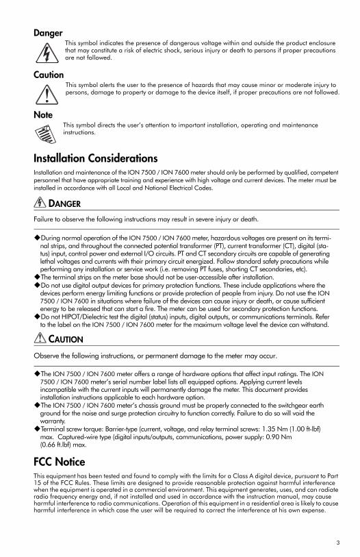
DangerThis symbol indicates the presence of dangerous voltage within and outside the product enclosure that may constitute a risk of electric shock, serious injury or death to persons if proper precautions are not followed.
CautionThis symbol alerts the user to the presence of hazards that may cause minor or moderate injury to persons, damage to property or damage to the device itself, if proper precautions are not followed.
NoteThis symbol directs the user’s attention to important installation, operating and maintenance instructions.
Installation ConsiderationsInstallation and maintenance of the ION 7500 / ION 7600 meter should only be performed by qualified, competent personnel that have appropriate training and experience with high voltage and current devices. The meter must be installed in accordance with all Local and National Electrical Codes.
DANGER
Failure to observe the following instructions may result in severe injury or death.
During normal operation of the ION 7500 / ION 7600 meter, hazardous voltages are present on its termi-nal strips, and throughout the connected potential transformer (PT), current transformer (CT), digital (sta-tus) input, control power and external I/O circuits. PT and CT secondary circuits are capable of generating lethal voltages and currents with their primary circuit energized. Follow standard safety precautions while performing any installation or service work (i.e. removing PT fuses, shorting CT secondaries, etc).The terminal strips on the meter base should not be user-accessible after installation.Do not use digital output devices for primary protection functions. These include applications where the devices perform energy limiting functions or provide protection of people from injury. Do not use the ION 7500 / ION 7600 in situations where failure of the devices can cause injury or death, or cause sufficient energy to be released that can start a fire. The meter can be used for secondary protection functions.Do not HIPOT/Dielectric test the digital (status) inputs, digital outputs, or communications terminals. Refer to the label on the ION 7500 / ION 7600 meter for the maximum voltage level the device can withstand.
CAUTION
Observe the following instructions, or permanent damage to the meter may occur.
The ION 7500 / ION 7600 meter offers a range of hardware options that affect input ratings. The ION 7500 / ION 7600 meter’s serial number label lists all equipped options. Applying current levels incompatible with the current inputs will permanently damage the meter. This document provides installation instructions applicable to each hardware option.The ION 7500 / ION 7600 meter’s chassis ground must be properly connected to the switchgear earth ground for the noise and surge protection circuitry to function correctly. Failure to do so will void the warranty.Terminal screw torque: Barrier-type (current, voltage, and relay terminal screws: 1.35 Nm (1.00 ft-lbf) max. Captured-wire type (digital inputs/outputs, communications, power supply: 0.90 Nm (0.66 ft.lbf) max.
FCC NoticeThis equipment has been tested and found to comply with the limits for a Class A digital device, pursuant to Part 15 of the FCC Rules. These limits are designed to provide reasonable protection against harmful interference when the equipment is operated in a commercial environment. This equipment generates, uses, and can radiate radio frequency energy and, if not installed and used in accordance with the instruction manual, may cause harmful interference to radio communications. Operation of this equipment in a residential area is likely to cause harmful interference in which case the user will be required to correct the interference at his own expense.
3

The Ringer Equivalence Number (REN) for the ION 7500 / ION 7600 optional internal modem is 0.6. Connection to the ION 7500 / ION 7600 internal modem should be made via an FCC Part 68 compliant telephone cord (not supplied). The ION 7500 / ION 7600 cannot be used on a public coin phone service or party line services.
Network Compatibility Notice for the Internal ModemThe internal modem in meters equipped with this option is compatible with the telephone systems of most countries in the world, with the exception of Australia and New Zealand. Use in some countries may require modification of the internal modem’s initialization strings. If problems using the modem on your phone system occur, please contact Power Measurement Technical Support
Standards Compliance
Limitation of LiabilityPower Measurement Ltd. (“Power Measurement”) reserves the right to make changes in the device or its specifications identified in this document without notice. Power Measurement advises customers to obtain the latest version of the device specifications before placing orders to verify that the information being relied upon by the customer is current.
Regardless of whether any remedy set forth herein fails of its essential purpose, except to the extent the following limitation is prohibited by applicable law, Power Measurement shall not, in any event or under any legal claim or theory (whether based on contract, indemnity, warranty, tort (including negligence and strict liability) or otherwise), be liable to the original purchaser or any other person or entity for special, indirect, incidental, punitive, liquidated, special or consequential damages whatsoever with respect to any purchased product, including, without limitation, business interruption, loss of use, profit or revenue, even if Power Measurement has been advised of the possibility of such damages. To the extent that a limitation or exclusion of consequential damages are prohibited by applicable law, then Power Measurement’s liability shall be limited to twice the amount of the relevant purchased product. Not to limit the foregoing, a) Power Measurement shall not be liable for any claim (other than a claim solely for the breach of one of the above Warranties that is made in accordance with the above described procedures) made by the original purchaser, its employees, agents, or contractors for any loss, damage, or expense incurred due to, caused by, or related to any purchased product; and b) the above Warranties are the original purchaser's exclusive remedy and Power Measurement hereby expressly disclaims all other warranties, express or implied, including, without limitation, warranties of non-infringement and the implied warranties of merchantability and fitness for a particular purpose.
These limited Warranties shall not apply to any product that has been subject to alteration, accident, misuse, abuse, neglect or failure to exactly follow Power Measurement's instructions for operation and maintenance. Any technical assistance provided by Power Measurement's personnel or representatives in system design shall be deemed to be a proposal and not a recommendation. The responsibility for determining the feasibility of such proposals rests with the original purchaser and should be tested by the original purchaser. It is the original purchaser’s responsibility to determine the suitability of any product and associated documentation for its purposes. The original purchaser acknowledges that 100% "up" time is not realizable because of possible hardware or software defects. The original purchaser recognizes that such defects and failures may cause inaccuracies or malfunctions. Only the terms expressed in these limited Warranties shall apply and no distributor, corporation or other entity, individual or employee of Power Measurement or any other entity is authorized to amend, modify or extend the Warranties in any way.
The information contained in this document is believed to be accurate at the time of publication, however, Power Measurement assumes no responsibility for any errors which may appear here and reserves the right to make changes without notice.
ION, ION Enterprise, ION Setup, ION Wire, PEGASYS, ION 6200, ION 7300, ION 7330, ION 7350, ION 7500, ION 7600, ION 7700, ION 8300, ION 8400, ION 8500, COM32, COM128, Vista, VIP, Designer, Reporter, MeterM@il, WebMeter, EtherGate, ModemGate, Xpress Card, Energy Profiler, Energy Profiler Online, Energy BOSS, E-VEE and "smart energy everywhere" are either registered trademarks or trademarks of Power Measurement. All other trademarks are property of their respective owners.
Covered by one or more of the following patents:
U.S. Patent No's 6751562, 6745138, 6737855, 6694270, 6687627, 6671654, 6671635, 6615147, 6611922, 6611773, 6563697, 6493644, 6397155, 6186842, 6185508, 6000034, 5995911, 5828576, 5736847, 5650936, D459259, D458863, D443541, D439535, D435471, D432934, D429655, D429533, D427533.
CSA: Certified to CAN/CSA C22.2 No.1010-1
Certified to UL 3111
CE: approved
4
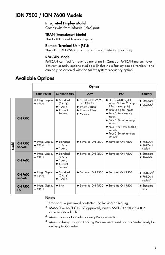
ION 7500 / ION 7600 ModelsIntegrated Display ModelComes with front infrared (IrDA) port.
TRAN (transducer) ModelThe TRAN model has no display.
Remote Terminal Unit (RTU)The RTU (ION 7500 only) has no power metering capability.
RMICAN ModelRMICAN-certified for revenue metering in Canada. RMICAN meters have different security options available (including a factory-sealed version), and can only be ordered with the 60 Hz system frequency option.
Available Options
Notes1 Standard = password protected, no locking or sealing.2 RMANSI = ANSI C12.16 approved; meets ANSI C12.20 class 0.2
accuracy standards.3 Meets Industry Canada Locking Requirements.4 Meets Industry Canada Locking Requirements and Factory Sealed (only for
delivery to Canada).
Option
Form Factor Current Inputs COM I/O Security
Mod
el
ION 7500
Integ. DisplayTRAN
Standard(5 Amp)1 AmpCurrent Probes
Standard (RS-232 and RS-485)Ethernet RJ45Ethernet FiberModem
Standard (8 digital inputs, 3 Form C relays, 4 Form A outputs)Extra 8 digital inputsFour 0-1mA analog inputsFour 0-20 mA analog inputsFour -1 to 1mA analog outputsFour 0-20 mA analog outputs
Standard1
RMANSI2
ION 7500 RMICAN
Integ. DisplayTRAN
Standard(5 Amp)1 Amp
Same as ION 7500 Same as ION 7500 RMICANRMICAN sealed
ION 7600
Integ. DisplayTRAN
Standard(5 Amp)1 AmpCurrent Probes
Same as ION 7500 Same as ION 7500 StandardRMANSI
ION 7600 RMICAN
Integ. DisplayTRAN
Standard(5 Amp)1 Amp
Same as ION 7500 Same as ION 7500 RMICAN3
RMICAN sealed4
ION 7500RTU
Integ. DisplayTRAN
N/A Same as ION 7500 Same as ION 7500 Standard only
5
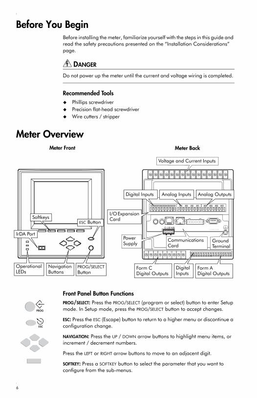
Before You BeginBefore installing the meter, familiarize yourself with the steps in this guide and read the safety precautions presented on the “Installation Considerations” page.
DANGER
Do not power up the meter until the current and voltage wiring is completed.
Recommended ToolsPhillips screwdriverPrecision flat-head screwdriverWire cutters / stripper
Meter Overview
Front Panel Button FunctionsPROG/SELECT: Press the PROG/SELECT (program or select) button to enter Setup mode. In Setup mode, press the PROG/SELECT button to accept changes.
ESC: Press the ESC (Escape) button to return to a higher menu or discontinue a configuration change.
NAVIGATION: Press the UP / DOWN arrow buttons to highlight menu items, or increment / decrement numbers.
Press the LEFT or RIGHT arrow buttons to move to an adjacent digit.
SOFTKEY: Press a SOFTKEY button to select the parameter that you want to configure from the sub-menus.
G N _L +
AI4 AO4AI3 A03AI2 A02AI1 AO1DI1DI2DI3DI4DI5DI6DI7DI8DICOM
TXDTXD
RXD
DCD
C COM ARD
NavigationButtons
PROG/SELECT Button
SoftkeysESC Button
CommunicationsCard
Form C Digital Outputs
DigitalInputs
Form A Digital Outputs
Digital Inputs Analog Inputs Analog Outputs
Voltage and Current Inputs
Power Supply Ground
Terminal
Meter Front Meter Back
IrDA Port
I/O Expansion Card
Operational LEDs
PROG
ESC
6
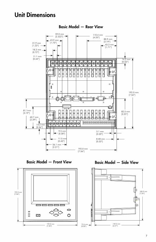
Unit Dimensions
31.9 mm[1.23“]
59.0 mm[2.322“]
110.4 mm[4.35“]
80.9 mm[3.19“]
43.3 mm[1.71“]
192.0 mm[7.56“]
82.5 mm[3.25“]
5.1 mm[0.20“]
8.48 mm[0.33“]
192.0 mm[7.56“]
56.1 mm[2.21“]
11.5 mm[0.45“]
9.5 mm[0.38“]
60.7 mm[2.39“]
81.1mm[3.19“]
14.2 mm[0.56“]
14.2 mm[0.56“]
43.9 mm[1.73“]
18.3 mm[0.72“]
11.1 mm[0.44“]
Basic Model — Rear View
192.0 mm[7.56“]
192.0 mm[7.56“]
12.6 mm[0.50“]
159.2 mm[6.27“]
183.9 mm[7.24“]
Basic Model — Front View Basic Model — Side View
7
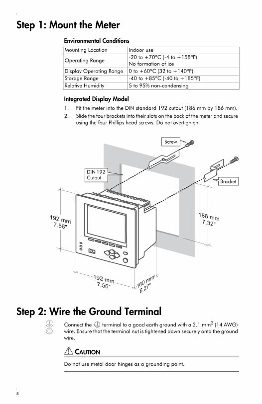
Step 1: Mount the MeterEnvironmental Conditions
Integrated Display Model 1. Fit the meter into the DIN standard 192 cutout (186 mm by 186 mm).
2. Slide the four brackets into their slots on the back of the meter and secure using the four Phillips head screws. Do not overtighten.
Step 2: Wire the Ground TerminalConnect the terminal to a good earth ground with a 2.1 mm2 (14 AWG) wire. Ensure that the terminal nut is tightened down securely onto the ground wire.
CAUTION
Do not use metal door hinges as a grounding point.
Mounting Location Indoor use
Operating Range-20 to +70ºC (-4 to +158ºF) No formation of ice
Display Operating Range 0 to +60ºC (32 to +140ºF)Storage Range -40 to +85ºC (-40 to +185ºF)Relative Humidity 5 to 95% non-condensing
Screw
Bracket
DIN 192 Cutout
8
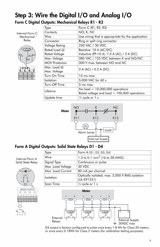
Step 3: Wire the Digital I/O and Analog I/O Form C Digital Outputs: Mechanical Relays R1 - R3
Form A Digital Outputs: Solid State Relays D1 - D4
Type Form C (R1, R2, R3) Contacts NO, K, NCWire Use wiring that is appropriate for the applicationConnector Ring or split ring connectorVoltage Rating 250 VAC / 30 VDCRated Load @Rated Voltage
Resistive: 10 A (AC/DC)Inductive (PF=0.4): 7.5 A (AC) / 5 A (DC)
Max. Voltage 380 VAC / 125 VDC between K and NO/NCMOV Protection 300 V max. between NO and NCMax. Load @Max. Voltage
3 A (AC) / 0.2 A (DC)
Turn-On Time 15 ms max.Isolation 5,000 VAC for 60 sTurn-Off Time 5 ms max.
LifetimeNo load = 10,000,000 operationsRated voltage and load = 100,000 operations
Update time ½ cycle or 1 s
R11 R12 R13 R21
R12
R11 R13
Internal Form C Mechanical
Relay
External Supply
Alarm Lamp
NCNO
Load
MeterK
Type Form A (D1, D2, D3, D4)
Wire 1.3 to 0.1 mm2 (16 to 28 AWG)Signal Type Continuous or pulse Max. Load Voltage 30 VDCMax. Load Current 80 mA per channel
IsolationOptically isolated; max. 5,000 V RMS isolation(UL-E91231)
Scan Time ½ cycle or 1 s
DIGITAL OUTPUTS
D3- +
D2- +
D4- +
D1- +
1.8 Wh
+_
D1
Internal Form A Solid State Relay
D4 output is factory-configured to pulse once every 1.8 Wh for Class 20 meters, or once every 0.18Wh for Class 2 meters (for calibration testing purposes).
+
+_
D3
_
D2
+ _ _ + _ +_
+_
D1
+
Meter
External Relays External Supply
30VDC max
9
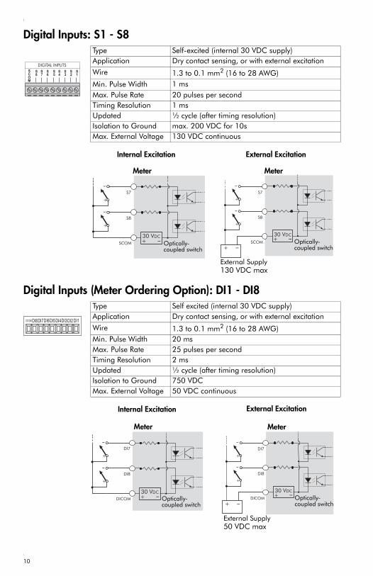
Digital Inputs: S1 - S8
Digital Inputs (Meter Ordering Option): DI1 - DI8
Type Self-excited (internal 30 VDC supply)Application Dry contact sensing, or with external excitation
Wire 1.3 to 0.1 mm2 (16 to 28 AWG)Min. Pulse Width 1 msMax. Pulse Rate 20 pulses per secondTiming Resolution 1 msUpdated ½ cycle (after timing resolution)Isolation to Ground max. 200 VDC for 10sMax. External Voltage 130 VDC continuous
SCOM
S1
S2
S3
S4
S5
S6
S7
S8
DIGITAL INPUTS
S8
S7
SCOM+ _30 VDC
+
_
+
_
_+
S8
S7
SCOM+ _30 VDC
+
_
+
_
Internal Excitation External Excitation
Optically-coupled switch
External Supply130 VDC max
Meter Meter
Optically-coupled switch
Type Self excited (internal 30 VDC supply)Application Dry contact sensing, or with external excitation
Wire 1.3 to 0.1 mm2 (16 to 28 AWG)Min. Pulse Width 20 msMax. Pulse Rate 25 pulses per secondTiming Resolution 2 msUpdated ½ cycle (after timing resolution)Isolation to Ground 750 VDCMax. External Voltage 50 VDC continuous
DI1DI2DI3DI4DI5DI6DI7DI8DICOM
DI8
DI7
DICOM+ _30 VDC
+
_
+
_
DI8
DI7
+
_
+
_
_+ DICOM+ _30 VDC
Internal Excitation External Excitation
Optically-coupled switch
Optically-coupled switch
External Supply50 VDC max
Meter Meter
10
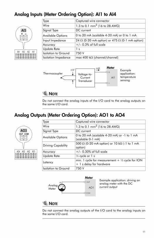
Analog Inputs (Meter Ordering Option): AI1 to AI4
NOTE
Do not connect the analog inputs of the I/O card to the analog outputs onthe same I/O card.
Analog Outputs (Meter Ordering Option): AO1 to AO4
NOTE
Do not connect the analog outputs of the I/O card to the analog inputs onthe same I/O card.
Type Captured wire connector
Wire 1.3 to 0.1 mm2 (16 to 28 AWG)Signal Type DC current
Available Options 0 to 20 mA (scalable 4-20 mA) or 0 to 1 mA
Input Impedance 24 Ω (0-20 mA option) or 475 Ω (0-1 mA option)Accuracy +/– 0.3% of full scaleUpdate Rate 1 sIsolation to Ground 750 VIsolation Impedance max 400 kΩ (channel/channel)
AI4 AI3 AI2 AI1
AI3+ -
Example application: temperature sensing
AI1
+
-
mVmA
Thermocoupler Voltage-to-Current
Transducer
Meter
Type Captured wire connector
Wire 1.3 to 0.1 mm2 (16 to 28 AWG)Signal Type DC current
Available Options0 to 20 mA (scalable 4-20 mA) or -1 to 1 mA (scalable 0-1 mA)
Driving Capability500 Ω (0-20 mA option) or 10 kΩ (-1 to 1 mA option)
Accuracy +/– 0.30% of full scaleUpdate Rate ½ cycle or 1 s
Latencymin. 1 cycle for measurement + ½ cycle for ION + 1 s delay for hardware
Isolation to Ground 750 V
AO3OUT COM
AO4 A03 A02 AO1
Example application: driving an analog meter with the DC current outputAO1
OUT
COM
+Meter
Analog Meter
11
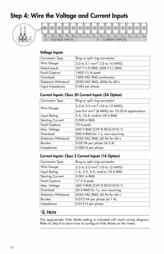
Step 4: Wire the Voltage and Current Inputs
Voltage Inputs
Current Inputs: Class 20 Current Inputs (5A Option)
Current Inputs: Class 2 Current Inputs (1A Option)
NOTE
The appropriate Volts Mode setting is included with each wiring diagram.Refer to Step 8 to learn how to configure Volts Mode on the meter.
3~ VOLTAGE INPUTS 3~ CURRENT INPUTSV3 V4 Vref I11 I12 I21 I22 I31 I32 I41 I42 I51V1 V2 I52
Connector Type Ring or split ring connector
Wire Gauge 3.3 to 2.1 mm2 (12 to 14 AWG)Rated Inputs 347 V L-N RMS /600 V L-L RMSFault Capture 1400 V L-N peakOverload 1500 VAC RMS continuousDielectric Withstand 3250 VAC RMS, 60Hz for 60 sInput Impedance 5 MΩ per phase
Connector Type Ring or split ring connector
Wire Gauge5.3 to 3.3 mm2 (10 to 12 AWG):
Use 8.4 mm2 (8 AWG) for 10-20 A applications Input Rating 5 A, 10 A, and/or 20 A RMSStarting Current 0.005 A RMSFault Capture 70 A peakMax. Voltage 600 V RMS (CAT III IEC61010-1)Overload 500 A RMS for 1 s, non-recurringDielectric Withstand 3250 VAC RMS, 60 Hz for 60 sBurden 0.05 VA per phase (at 5 A)Impedance 0.002 Ω per phase
Connector Type Ring or split ring connector
Wire Gauge 5.3 to 3.3 mm2 (10 to 12 AWG)Input Rating 1 A, 2 A, 5 A, and/or 10 A RMSStarting Current 0.001 A RMSFault Capture 17.5 A peakMax. Voltage 600 V RMS (CAT III IEC61010-1)Overload 50 A RMS for 1s, non-recurringDielectric Withstand 3250 VAC RMS, 60 Hz for 60 sBurden 0.015 VA per phase (at 1 A)Impedance 0.015 Ω per phase
12
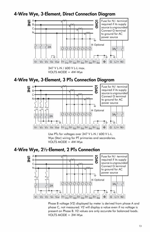
4-Wire Wye, 3-Element, Direct Connection Diagram
347 V L-N / 600 V L-L max.VOLTS MODE = 4W-Wye
4-Wire Wye, 3-Element, 3 PTs Connection Diagram
Use PTs for voltages over 347 V L-N / 600 V L-L.Wye (Star) wiring for PT primaries and secondaries.VOLTS MODE = 4W-Wye
4-Wire Wye, 2½-Element, 2 PTs Connection
Phase B voltage (V2) displayed by meter is derived from phase A and phase C, not measured. V2 will display a value even if no voltage is present on Phase B. V2 values are only accurate for balanced loads.VOLTS MODE = 3W-Wye
2A
V1 V2 V3 Vref I11I12
I21I22
I31I32
A
B
C
N
N/-L /+G
3A
I41I42
I51I52V4
I4 Optional
LINE
LOA
D
Fuse for N/- terminal required if its supply source is ungrounded Connect G terminalto ground for AC power source
V1 V2 V3 Vref I11I12
I21I22
I31I32 N/-L /+G
3A
A
B
C
N
2A
I41I42
I51I52
I4 Optional
V4
LINE
LOA
D
Fuse for N/- terminal required if its supply source is ungrounded Connect G terminalto ground for AC power source
V1 V2 V3 Vref I11I12
I21I22
I31I32 N/-L /+G
3A
A
B
C
N
2A
V4 I41I42
I51I52
I4 Optional
LINE
LOA
D
Fuse for N/- terminal required if its supply source is ungrounded Connect G terminalto ground for AC power source
13

3-Wire Solid-Grounded Wye, 3-Element, Direct Connection
When the common or star point of a 3-wire Wye system is grounded, the meter may be connected directly without using PTs, provided that the phase voltages are within the meter’s range.VOLTS MODE = 4W-Wye
3-Wire Delta, 2½-Element, Direct Connection
600 V L-L max.VOLTS MODE = Delta
3-Wire Delta, 2-Element 2 PTs & 2 CTs
Use PTs for voltages over 600 V L-L.VOLTS MODE = Delta
V1 V2 V3 Vref I11I12
I21I22
I31I32
2A
A
B
C
N/-L /+G
3A
N
V4 I41I42
I51I52
LINE
LOA
D
Fuse for N/- terminal required if its supply source is ungrounded Connect G terminalto ground for AC power source
V1 V2 V3 Vref I11I12
I21I22
I31I32 N/-L /+G
3A
A
B
C
2A
Do notconnect
V4 I41I42
I51I52
LINE
LOA
D
Fuse for N/- terminal required if its supply source is ungrounded Connect G terminalto ground for AC power source
V1 V2 V3 Vref I11I12
I21I22
I31I32 N/-L /+G
3A
A
B
C
2A
V4 I41I42
I51I52
LINE
LOA
D
Fuse for N/- terminal required if its supply source is ungrounded Connect G terminalto ground for AC power source
14
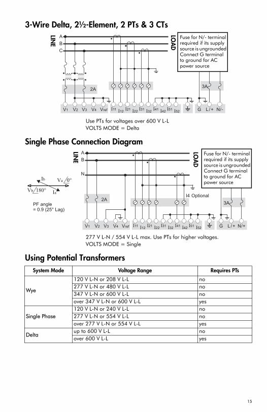
3-Wire Delta, 2½-Element, 2 PTs & 3 CTs
Use PTs for voltages over 600 V L-LVOLTS MODE = Delta
Single Phase Connection Diagram
277 V L-N / 554 V L-L max. Use PTs for higher voltages.VOLTS MODE = Single
Using Potential Transformers
2A
V1 V2 V3 Vref I11I12
I21I22
I31I32 N/-L /+G
3A
A
B
C
V4 I41I42
I51I52
LINE
LOA
D
Fuse for N/- terminal required if its supply source is ungrounded Connect G terminalto ground for AC power source
V1 V2 V3 Vref I11I12
I21I22
I31I32
2A
A
B
N
N/+L/+G
3APF angle= 0.9 (25° Lag)
Ib
Ia
Va 0°
V 18b 0°
V4
I4 Optional
I41I42
I51I52
LINE
LOA
D
Fuse for N/- terminal required if its supply source is ungrounded Connect G terminalto ground for AC power source
System Mode Voltage Range Requires PTs
Wye
120 V L-N or 208 V L-L no277 V L-N or 480 V L-L no347 V L-N or 600 V L-L noover 347 V L-N or 600 V L-L yes
Single Phase120 V L-N or 240 V L-L no277 V L-N or 554 V L-L noover 277 V L-N or 554 V L-L yes
Deltaup to 600 V L-L noover 600 V L-L yes
15
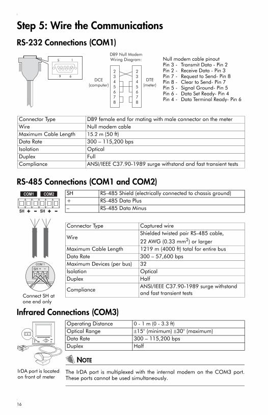
Step 5: Wire the Communications
RS-232 Connections (COM1)
RS-485 Connections (COM1 and COM2)
Infrared Connections (COM3)
NOTE
The IrDA port is multiplexed with the internal modem on the COM3 port.These ports cannot be used simultaneously.
5 1
9 6
2345678
2345678
DB9 Null ModemWiring Diagram:
DCE(computer)
DTE(meter)
Null modem cable pinoutPin 3 - Transmit Data - Pin 2Pin 2 - Receive Data - Pin 3Pin 7 - Request to Send- Pin 8Pin 8 - Clear to Send- Pin 7Pin 5 - Signal Ground- Pin 5Pin 6 - Data Set Ready- Pin 4Pin 4 - Data Terminal Ready- Pin 6
Connector Type DB9 female end for mating with male connector on the meterWire Null modem cableMaximum Cable Length 15.2 m (50 ft)Data Rate 300 – 115,200 bpsIsolation OpticalDuplex FullCompliance ANSI/IEEE C37.90-1989 surge withstand and fast transient tests
SH RS-485 Shield (electrically connected to chassis ground)+ RS-485 Data Plus– RS-485 Data Minus
Connector Type Captured wire
WireShielded twisted pair RS-485 cable,
22 AWG (0.33 mm2) or largerMaximum Cable Length 1219 m (4000 ft) total for entire busData Rate 300 – 57,600 bpsMaximum Devices (per bus) 32Isolation OpticalDuplex Half
ComplianceANSI/IEEE C37.90-1989 surge withstand and fast transient tests
SH + -
COM 1
Connect SH at one end only
Operating Distance 0 - 1 m (0 - 3.3 ft)Optical Range ±15° (minimum) ±30° (maximum)Data Rate 300 – 115,200 bps Duplex Half
IrDA port is located on front of meter
16
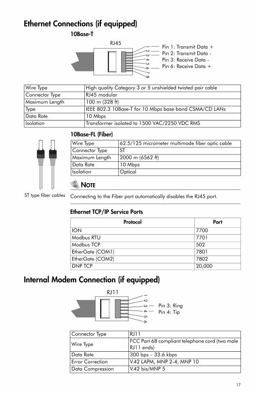
Ethernet Connections (if equipped)10Base-T
10Base-FL (Fiber)
NOTE
Connecting to the Fiber port automatically disables the RJ45 port.
Ethernet TCP/IP Service Ports
Internal Modem Connection (if equipped)
Pin 1: Transmit Data +Pin 2: Transmit Data -Pin 3: Receive Data -Pin 6: Receive Data +
12
34
56
78
RJ45
Wire Type High quality Category 3 or 5 unshielded twisted pair cableConnector Type RJ45 modularMaximum Length 100 m (328 ft)Type IEEE 802.3 10Base-T for 10 Mbps base band CSMA/CD LANsData Rate 10 MbpsIsolation Transformer isolated to 1500 VAC/2250 VDC RMS
Wire Type 62.5/125 micrometer multimode fiber optic cableConnector Type STMaximum Length 2000 m (6562 ft)Data Rate 10 MbpsIsolation Optical
Protocol Port
ION 7700Modbus RTU 7701Modbus TCP 502EtherGate (COM1) 7801EtherGate (COM2) 7802DNP TCP 20,000
ST type fiber cables
Pin 3: RingPin 4: Tip
RJ11 12
34
56
Connector Type RJ11
Wire TypeFCC Part 68 compliant telephone cord (two male RJ11 ends)
Data Rate 300 bps – 33.6 kbpsError Correction V.42 LAPM, MNP 2-4, MNP 10Data Compression V.42 bis/MNP 5
17
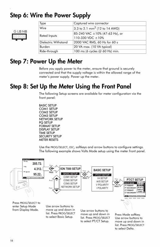
Step 6: Wire the Power Supply
Step 7: Power Up the MeterBefore you apply power to the meter, ensure that ground is securely connected and that the supply voltage is within the allowed range of the meter’s power supply. Power up the meter.
Step 8: Set Up the Meter Using the Front PanelThe following Setup screens are available for meter configuration via the front panel:
Use the PROG/SELECT, ESC, softkeys and arrow buttons to configure settings. The following example shows Volts Mode setup using the meter front panel.
Type Captured wire connector
Wire 3.3 to 2.1 mm2 (12 to 14 AWG)
Rated Inputs 85-240 VAC ±10% (47-63 Hz), or 110-330 VDC ±10%
Dielectric Withstand 2000 VAC RMS, 60 Hz for 60 sBurden 20 VA max. (10 VA typical)Ride-through 100 ms (6 cycles @ 60 Hz) min.
G N _L +
BASIC SETUPCOM1 SETUPCOM2 SETUPCOM3 SETUPNETWORK SETUPPQ SETUPFORMAT SETUPDISPLAY SETUPTIME SETUPSECURITY SETUPMETER RESETS
Press PROG/SELECT to enter Setup Mode from Display Mode.
Use arrow buttons to move up and down in list. Press PROG/SELECT to select Basic Setup.
Use arrow buttons to move up and down in list. Press PROG/SELECT to select PT/CT Setup.
Press Mode softkey. Use arrow buttons to move up and down in list. Press PROG/SELECT to select Delta.
18

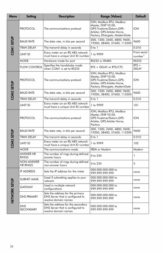
The following table lists all settings that can be configured via the front panel.
Menu Setting Description Range (Values) Default
BASI
C SE
TUP
VOLTS MODE The power system’s configuration – WYE, DELTA, etc.
4W-WYEDELTA3W-WYESINGLEDEMO
4W-WYE
PT PRIMARY The Potential Transformer’s primary winding voltage rating 1 to 999,999.99 120.00
PT SECONDARY The Potential Transformer’s secondary winding voltage rating 1 to 999,999.99 120.00
CT PRIMARY The Current Transformer’s primary winding current rating 1 to 999,999.99 5.00
CT SECONDARY The Current Transformer’s secondary winding current rating 1 to 999,999.99 5.00
V4 PRIMARY The Potential Transformer’s primary winding voltage rating on V4 1 to 999,999.99 120.00
V4 SECONDARYThe Potential Transformer’s secondary winding voltage rating on V4
1 to 999,999.99 120.00
I4 PRIMARY The Current Transformer’s primary winding current rating on I4 1 to 999,999.99 5.00
I4 SECONDARYThe Current Transformer’s secondary winding current rating on I4
1 to 999,999.99 5.00
I5 PRIMARY The Current Transformer’s primary winding current rating on I5 1 to 999,999.99 5.00
I5 SECONDARYThe Current Transformer’s secondary winding current rating on I5
1 to 999,999.99 5.00
Va POLARITY The polarity of the Potential Transformer on Va Normal or Inverted Normal
Vb POLARITY The polarity of the Potential Transformer on Vb Normal or Inverted Normal
Vc POLARITY The polarity of the Potential Transformer on Vc Normal or Inverted Normal
V4 POLARITY The polarity of the Potential Transformer on V4 Normal or Inverted Normal
Ia POLARITY The polarity of the Current Transformer on Ia Normal or Inverted Normal
Ib POLARITY The polarity of the Current Transformer on Ib Normal or Inverted Normal
Ic POLARITY The polarity of the Current Transformer on Ic Normal or Inverted Normal
I4 POLARITY The polarity of the Current Transformer on I4 Normal or Inverted Normal
I5 POLARITY The polarity of the Current Transformer on I5 Normal or Inverted Normal
CURRENT PROBE TYPE
The type of current probes being used with the meter
Factory Default, User Defined 1, or User Defined 2
Factory Default
19
COM
1 SE
TUP
PROTOCOL The communications protocol
ION, Modbus RTU, Modbus Master, DNP V3.00, GPS:Truetime/Datum,GPS: Arbiter, GPS:Arbiter-Vorne, Factory, Ethergate, ModemGate
ION
BAUD RATE The data rate, in bits per second 300, 1200, 2400, 4800, 9600, 19200, 38400, 57600, 115200 9600
TRAN DELAY The transmit delay in seconds 0 to 1 0.010
UNIT ID Every meter on an RS-485 network must have a unique Unit ID number 1 to 9999
From serial number1
MODE Hardware mode for port RS232 or RS485 RS232
FLOW CONTROL Specifies the handshake mode when COM1 is set to RS232 RTS + DELAY or RTS/CTS RTS +
DELAY
COM
2 SE
TUP PROTOCOL The communications protocol
ION, Modbus RTU, Modbus Master, DNP V3.00, GPS:Truetime/Datum,GPS: Arbiter, GPS:Arbiter-Vorne, Factory, Ethergate, ModemGate
ION
BAUD RATE The data rate, in bits per second 300, 1200, 2400, 4800, 9600, 19200, 38400, 57600, 115200 9600
TRAN DELAY The transmit delay in seconds 0 to 1 0.010
UNIT ID Every meter on an RS-485 network must have a unique Unit ID number 1 to 9999 101
COM
3 SE
TUP
PROTOCOL The communications protocol
ION, Modbus RTU, Modbus Master, DNP V3.00, GPS:Truetime/Datum,GPS: Arbiter, GPS:Arbiter-Vorne, Factory
ION
BAUD RATE The data rate, in bits per second 300, 1200, 2400, 4800, 9600, 19200, 38400, 57600, 115200 9600
TRAN DELAY The transmit delay in seconds 0 to 1 0.010
UNIT ID Every meter on an RS-485 network must have a unique Unit ID number 1 to 9999 102
MODE The communications mode IRDA or Modem Modem
ANSWER HR RINGS
The number of rings during defined answer hours 0 to 255 1
NON-ANSWER HR RINGS
The number of rings during defined non-answer hours 0 to 255 5
NET
WO
RK S
ETU
P
IP ADDRESS Sets the IP address for the meter 000.000.000.000 to 999.999.999.999 none
SUBNET MASK Used if subnetting applies to your network
000.000.000.000 to 999.999.999.999 none
GATEWAY Used in multiple network configurations
000.000.000.000 to 999.999.999.999 none
DNS PRIMARYSets the address for the primary DNS Server that is configured to resolve domain names
000.000.000.000 to 999.999.999.999 none
DNS SECONDARY
Sets the address for the secondary DNS Server that is configured to resolve domain names
000.000.000.000 to 999.999.999.999 none
Menu Setting Description Range (Values) Default
20
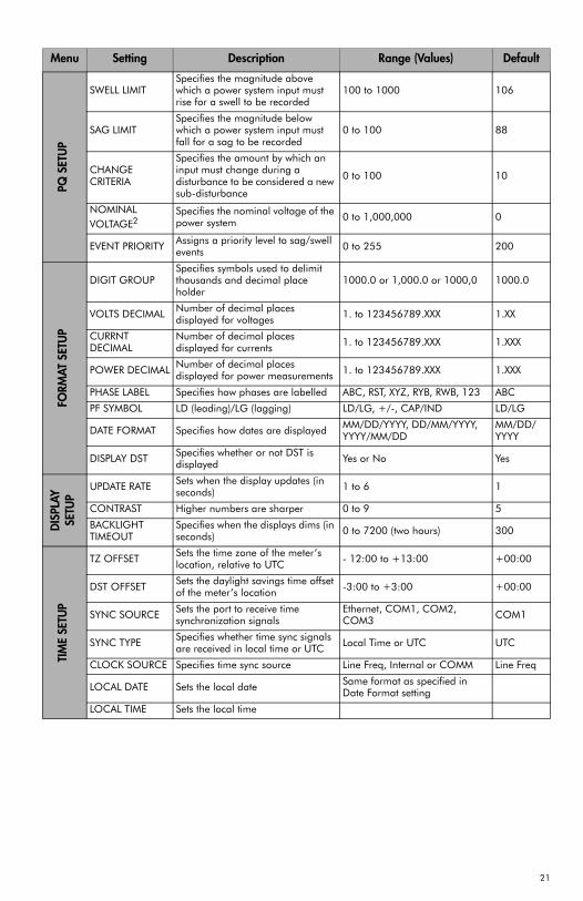
PQ S
ETU
P
SWELL LIMITSpecifies the magnitude above which a power system input must rise for a swell to be recorded
100 to 1000 106
SAG LIMITSpecifies the magnitude below which a power system input must fall for a sag to be recorded
0 to 100 88
CHANGE CRITERIA
Specifies the amount by which an input must change during a disturbance to be considered a new sub-disturbance
0 to 100 10
NOMINAL VOLTAGE2
Specifies the nominal voltage of the power system 0 to 1,000,000 0
EVENT PRIORITY Assigns a priority level to sag/swell events 0 to 255 200
FORM
AT S
ETU
P
DIGIT GROUPSpecifies symbols used to delimit thousands and decimal place holder
1000.0 or 1,000.0 or 1000,0 1000.0
VOLTS DECIMAL Number of decimal places displayed for voltages 1. to 123456789.XXX 1.XX
CURRNT DECIMAL
Number of decimal places displayed for currents 1. to 123456789.XXX 1.XXX
POWER DECIMAL Number of decimal places displayed for power measurements 1. to 123456789.XXX 1.XXX
PHASE LABEL Specifies how phases are labelled ABC, RST, XYZ, RYB, RWB, 123 ABC
PF SYMBOL LD (leading)/LG (lagging) LD/LG, +/-, CAP/IND LD/LG
DATE FORMAT Specifies how dates are displayed MM/DD/YYYY, DD/MM/YYYY, YYYY/MM/DD
MM/DD/YYYY
DISPLAY DST Specifies whether or not DST is displayed Yes or No Yes
DIS
PLAY
SETU
P
UPDATE RATE Sets when the display updates (in seconds) 1 to 6 1
CONTRAST Higher numbers are sharper 0 to 9 5
BACKLIGHT TIMEOUT
Specifies when the displays dims (in seconds) 0 to 7200 (two hours) 300
TIM
E SE
TUP
TZ OFFSET Sets the time zone of the meter’s location, relative to UTC - 12:00 to +13:00 +00:00
DST OFFSET Sets the daylight savings time offset of the meter’s location -3:00 to +3:00 +00:00
SYNC SOURCE Sets the port to receive time synchronization signals
Ethernet, COM1, COM2, COM3 COM1
SYNC TYPE Specifies whether time sync signals are received in local time or UTC Local Time or UTC UTC
CLOCK SOURCE Specifies time sync source Line Freq, Internal or COMM Line Freq
LOCAL DATE Sets the local date Same format as specified in Date Format setting
LOCAL TIME Sets the local time
Menu Setting Description Range (Values) Default
21
1 Serial number = PA-0302B222-01, Unit ID = 22222 NOMINAL VOLTAGE must be set to your system’s nominal voltage to
activate the meter’s power quality features.
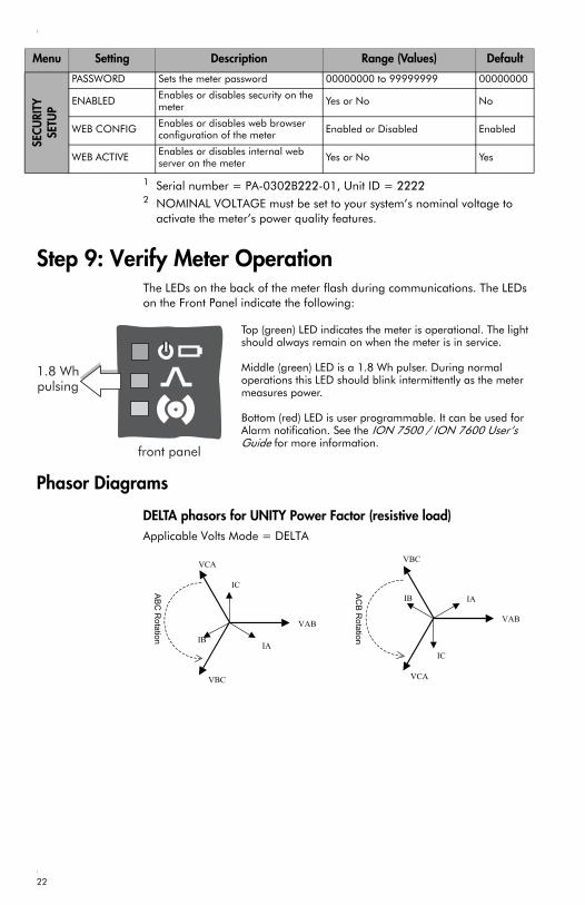
Step 9: Verify Meter OperationThe LEDs on the back of the meter flash during communications. The LEDs on the Front Panel indicate the following:
Phasor Diagrams
DELTA phasors for UNITY Power Factor (resistive load)Applicable Volts Mode = DELTA
SECU
RITY
SETU
P
PASSWORD Sets the meter password 00000000 to 99999999 00000000
ENABLED Enables or disables security on the meter Yes or No No
WEB CONFIG Enables or disables web browser configuration of the meter Enabled or Disabled Enabled
WEB ACTIVE Enables or disables internal web server on the meter Yes or No Yes
Menu Setting Description Range (Values) Default
Top (green) LED indicates the meter is operational. The light should always remain on when the meter is in service.
Middle (green) LED is a 1.8 Wh pulser. During normal operations this LED should blink intermittently as the meter measures power.
Bottom (red) LED is user programmable. It can be used for Alarm notification. See the ION 7500 / ION 7600 User’s Guide for more information.
IA
IC
IB
VAB
VBC
VCA
IA
IC
IB
VAB
VBC
VCA
ABC R
otation
ACB R
otation
22
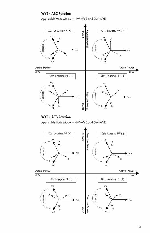
WYE - ABC RotationApplicable Volts Mode = 4W-WYE and 3W-WYE
WYE - ACB RotationApplicable Volts Mode = 4W-WYE and 3W-WYE
IAIB
VA
IB
IC
IA IC
VA
IB
VA
ICVC
VB
IA
VC
VB
IA
IC
IB
VA
VC
VB
VC
VB
Active Power +kW
Active Power -kW
Reactive Pow
er
+kVAR
Reactive P
owe r
-kVAR
Q1: Lagging PF (-) Q2: Leading PF (+)
Q4: Leading PF (+) Q3: Lagging PF (-)
Rotation
Rotation
Rotation
Rotation
ICIA
IB
VA
VB
VC
IAIB
IC
VA
VB
VC
IA
IB
IC
VA
VB
VC
IA
IC
IB
VA
VB
VC
Rotation
Rotation
Rotation
Rotation
Active Power +kW
Active Power -kW
Reactive P
ower
+kVAR
Reactive P
ower
-kVAR
Q1: Lagging PF (-) Q2: Leading PF (+)
Q4: Leading PF (+) Q3: Lagging PF (-)
23
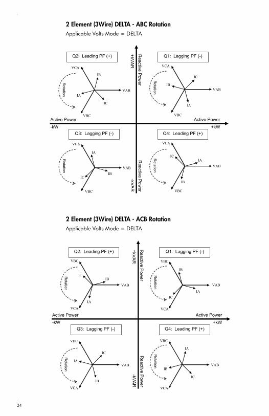
2 Element (3Wire) DELTA - ABC RotationApplicable Volts Mode = DELTA
2 Element (3Wire) DELTA - ACB RotationApplicable Volts Mode = DELTA
IA
IC
IBVAB
VCA
VBC
IAIC
IB
VAB
VCA
VBC
IA
IC IB
VAB
VCA
VBC
IA
IB
IC
VAB
VCA
VBC R
otation R
otation
Rotation
Rotation
Active Power +kW
Active Power -kW
Reactive P
ower
+kVAR
Reactive P
ower
-kVAR
Q1: Lagging PF (-)
Q4: Leading PF (+) Q3: Lagging PF (-)
Q2: Leading PF (+)
IA
IB
IC
VCA
VAB
VBC
IA
IB
IC
IA
IB
IC
IA
IC IB
VCA
VAB
VBC
VCA
VAB
VBC
VAB
VBC
VCA
Rotation
Rotation
Rotation
Rotation
Active Power +kW
Active Power -kW
Reactive P
ower
+kVAR
Reactive Pow
er
-kVAR
Q4: Leading PF (+) Q3: Lagging PF (-)
Q2: Leading PF (+) Q1: Lagging PF (-)
24
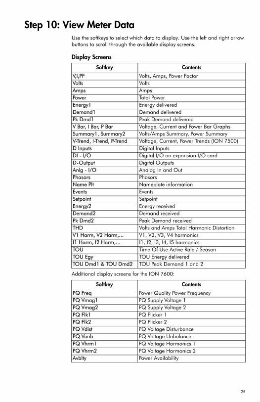
Step 10: View Meter DataUse the softkeys to select which data to display. Use the left and right arrow buttons to scroll through the available display screens.
Display Screens
Additional display screens for the ION 7600:
Softkey Contents
V,I,PF Volts, Amps, Power FactorVolts VoltsAmps AmpsPower Total PowerEnergy1 Energy deliveredDemand1 Demand deliveredPk Dmd1 Peak Demand deliveredV Bar, I Bar, P Bar Voltage, Current and Power Bar GraphsSummary1, Summary2 Volts/Amps Summary, Power SummaryV-Trend, I-Trend, P-Trend Voltage, Current, Power Trends (ION 7500)D Inputs Digital InputsDI - I/O Digital I/O on expansion I/O cardD-Output Digital OutputsAnlg - I/O Analog In and OutPhasors PhasorsName Plt Nameplate informationEvents EventsSetpoint SetpointEnergy2 Energy receivedDemand2 Demand receivedPk Dmd2 Peak Demand receivedTHD Volts and Amps Total Harmonic DistortionV1 Harm, V2 Harm,... V1, V2, V3, V4 harmonicsI1 Harm, I2 Harm,... I1, I2, I3, I4, I5 harmonicsTOU Time Of Use Active Rate / SeasonTOU Egy TOU Energy deliveredTOU Dmd1 & TOU Dmd2 TOU Peak Demand 1 and 2
Softkey Contents
PQ Freq Power Quality Power FrequencyPQ Vmag1 PQ Supply Voltage 1PQ Vmag2 PQ Supply Voltage 2PQ Flk1 PQ Flicker 1PQ Flk2 PQ Flicker 2PQ Vdist PQ Voltage DisturbancePQ Vunb PQ Voltage UnbalancePQ Vhrm1 PQ Voltage Harmonics 1PQ Vhrm2 PQ Voltage Harmonics 2Avblty Power Availability
25

26


For further assistanceplease contact us at:
Worldwide Headquarters2195 Keating Cross RoadSaanichton, BCCanada V8M 2A5Tel: 1-250-652-7101Fax: 1-250-652-0411Email: [email protected]
www.pwrm.com
© 2004 Power MeasurementPrinted in CanadaMRP: 70000-0187-06Revision Date: Jul. 20, 2004