iodetector: a generic service for indoor outdoor detection · iodetector: a generic service for...
TRANSCRIPT

IODetector: A Generic Service for Indoor Outdoor Detection
Pengfei Zhou†, Yuanqing Zheng†, Zhenjiang Li†, Mo Li†, and Guobin Shen‡†Nanyang Technological University, Singapore
‡Microsoft Research Asia, Beijing, China
{pfzhou, yuanqing1, lzjiang, limo}@ntu.edu.sg, [email protected]
AbstractThe location and context switching, especially the in-
door/outdoor switching, provides essential and primitive in-formation for upper layer mobile applications. In this paper,we present IODetector: a lightweight sensing service whichruns on the mobile phone and detects the indoor/outdoor en-vironment in a fast, accurate, and efficient manner. Con-strained by the energy budget, IODetector leverages pri-marily lightweight sensing resources including light sensors,magnetism sensors, celltower signals, etc. For universal ap-plicability, IODetector assumes no prior knowledge (e.g.,fingerprints) of the environment and uses only on-board sen-sors common to mainstream mobile phones. Being a genericand lightweight service component, IODetector greatly ben-efits many location-based and context-aware applications.We prototype the IODetector on Android mobile phonesand evaluate the system comprehensively with data collectedfrom 19 traces which include 84 different places during onemonth period, employing different phone models. We fur-ther perform a case study where we make use of IODetectorto instantly infer the GPS availability and localization accu-racy in different indoor/outdoor environments.
Categories and Subject DescriptorsC.2.4 [Computer Communication Networks]: Dis-
tributed Systems – Distributed Applications; C.3.3 [Special-Purpose and Application-based Systems]: Real-time andembedded systems
General TermsDesign, Implementation, Measurement
KeywordsIndoor and Outdoor Detection, Mobile Phones, GPS
Availability
Permission to make digital or hard copies of all or part of this work for personal orclassroom use is granted without fee provided that copies are not made or distributedfor profit or commercial advantage and that copies bear this notice and the full citationon the first page. To copy otherwise, to republish, to post on servers or to redistributeto lists, requires prior specific permission and/or a fee.
SenSys’12, November 6–9, 2012, Toronto, ON, Canada.Copyright c© 2012 ACM 978-1-4503-1169-4 ...$10.00
1 IntroductionCurrent mobile phones are becoming important platforms
that serve the ubiquitous sensing and communication needsof people [16]. The sensing and communication moduleson mobile phones are usually developed to provide locationand context-aware services. However, they may have het-erogenous availabilities and perform differently in differentenvironments. An effective indoor/outdoor detection schemecan provide primitive environment information for a varietyof mobile applications, and thus potentially improve the per-formance of mobile phones. For example, in location-basedapplications, people usually source GPS for an accurate loca-tion reference when they are in the outdoor environment. Incontrast, GPS performs poorly without line-of-sight paths tosatellites when mobile devices are inside buildings [5, 30].In mobile data services, mobile phones normally observemore WiFi Access Points (APs) with strong signals insidebuildings whereas it is unlikely to have good WiFi connec-tions in outdoor environments. Therefore, knowing indooror outdoor can help to make smarter decisions on whetherto turn on GPS or to perform AP scanning. In the contextand activity recognition applications, the knowledge of thesurrounding indoor/outdoor environment potentially leads tomore accurate recognition.
Although many applications may benefit from accurateand prompt indoor/outdoor information, the research studytowards generic indoor/outdoor detection surprisingly lacks.Many location related works simply assume a clear pre-knowledge on the indoor/outdoor environment has beenknown, but such an assumption hardly holds in practice. Theunavailability or performance degradation of GPS is some-times used to infer the indoor/outdoor environment, yet suchan approach suffers from low accuracy, high energy con-sumption, and long response time.
In this paper, we present the Indoor/Outdoor Detector(IODetector): a generic and light-weight service for the in-door/outdoor detection for mobile applications. Constrainedby the energy budget on mobile phones, we primarily makeuse of three types of lightweight sensors, i.e., light sensor,cellular module, and magnetism sensor. Through one monthexperiment, we observe that the light intensity, the cell towersignal, and the intensity of magnetic field all individuallyexhibit distinct patterns in the indoor and outdoor environ-ments. Those patterns turn out to be viable for an accurateclassification of the ambient environments. More precisely,

light signals exhibit distinct patterns when they are capturedinside and outside buildings respectively. The reason behindis that the natural and man-made light sources contain inher-ent difference in nature. The received signal strength from acell tower by a mobile phone changes dramatically from theoutdoor to indoor environments as the dividing walls blockthe line-of-sight paths between the mobile phone and the celltower. The intensity of magnetic field varies significantlyacross different places inside buildings due to the ambientelectric appliances and steel structures while remains muchless fluctuated across an outdoor environment. Motivated bythose facts and observations, we target at achieving the in-door/outdoor detection by exploiting the three lightweightsensing resources.
Translating such an idea into a practical indoor/outdoordetection service entails a wide range of challenges, as thethree aforementioned sensing resources show distinct prosand cons in different surrounding environments. The ambi-ent light intensity may vary over time and is potentially in-fluenced by various factors (e.g., people movement, phonepose, and cover of sight). The absolute cell tower signalstrength may vary significantly at different places and acrossdifferent mobile phone models, making it difficult to con-fidently set a uniform rule for the indoor/outdoor classifi-cation. The magnetometer readings are error-prone with-out careful calibrations. We develop practical solutions andaddress above challenges in IODetector. In particular, weextract unique identifiable indoor lighting features to de-tect the indoor/outdoor environment, and leverage particu-lar light intensity patterns to improve the detection accuracy(§3.2). We exploit the abrupt period of the cell tower signalstrength rather than its absolute value to distinguish the in-door/outdoor context that is invariant across different placesand phone models. We track the cellular signals from mul-tiple visible cell towers so as to enhance the robustness ofthe indoor/outdoor detection (§3.3). We take advantage ofthe magnetic disturbance inside buildings and make use ofthe movement status from accelerometers to ensure the de-tection performance (§3.4).
We constructively combine the three sensing componentsand develop an extensible indoor/outdoor detection frame-work. By taking other ambient sensing readings and eval-uating the confidence levels of three sensing units, we in-tellectually aggregate their detection results and guaranteeoptimized reliance on those sensing units. The developedIODetector then works as an underlying service module thatcan be invoked by upper-layer applications to provide instantindoor/outdoor information (§3.5).
We implement and evaluate IODetector with the Androidplatform using different mobile phone models. We testIODetector in 19 traces including 84 different sites in ourcampus and city areas, and demonstrate quite encouragingresults with various scenarios. Since IODetector only relieson lightweight sensors, the low energy cost allows continu-ous tracking of indoor/outdoor state transitions. In particular,we perform a case study and show that we can utilize IODe-tector to cheaply and accurately infer the current availabilityand accuracy of the GPS module for mobile phones.
The rest of this paper is organized as follow. In §2, we
first detail the background and motivation of this work. Wedescribe the technical solutions of IODetector in §3. Wepresent the evaluation results in §4 and review related worksin §5. Finally, we conclude the paper in §6.
2 Background and motivationThe indoor/outdoor detection can provide essential and
primitive information for upper-layer mobile applications.For example, before turning on GPS, one may first checkwhether it is outside a building to ensure the GPS per-formance. Another example is that before searching forWiFi access points, one may check whether it is inside ornear buildings and adapt the scanning strategy accordingly.Many other applications, including automatic image annota-tion [24], context and activity recognition [10], indoor local-ization [7], may also rely on the indoor/outdoor knowledgefor a proper working scheme. If the detection overhead (de-pending on the application profile) is sufficiently small, mostlocation and context-aware applications will greatly benefitfrom such indoor/outdoor detection.
While practically useful, the problem of indoor/outdoordetection has not been thoroughly studied yet. Existing lo-calization and tracking applications may indirectly infer theambient environment with the availability and accuracy ofthe GPS signal. It is well known that localization and track-ing systems perform poorly in the indoor environment as theline-of-sight paths to GPS satellites are blocked. The un-availability of GPS signals and the the decreasing numberof the visible satellites can thus infer the indoor environ-ment [25]. Typical GPS modules, however, draw substantialamount of energy and take minutes to warm up and conductthe GPS satellite scanning on mobile phones [30]. As a re-sult, detecting indoor/outdoor environments solely with GPScan be slow and inefficient. There are some other works re-lying on dedicated devices to assist the ambient environmentdetection. The deployment cost of such infrastructure-basedapproaches significantly limits the flexibility and scalabilityfor general purpose detection [27]. On the other hand, somerecent works study the problem of logical localization bysensing the surrounding environment [4, 19]. By painstak-ingly fingerprinting ambient signals (e.g., sound, floor color,user movement, etc), the mobile phones can learn the ambi-ent environment through an intensive site survey. A centralserver is normally needed to store such ambient fingerprintsand answer queries from users. Such an approach is unlikelyto be generalized to deal with universal indoor/outdoor de-tection. Many works in image processing and pattern recog-nition study the problem of the indoor/outdoor image clas-sification and automatic image tagging [23, 24, 28]. Suchapproaches cannot directly be applied to our problem, sincethey require explicit, manual input from users.
In this work, we propose IODetector, a lightweightindoor/outdoor detection framework, which independentlyruns on each mobile phone and provides generic service toupper-layer applications. As a basic component which mightbe frequently invoked by many applications on energy-constrained mobile phones, IODetector needs to meet sev-eral stringent design requirements.
• High accuracy. As a generic framework that many
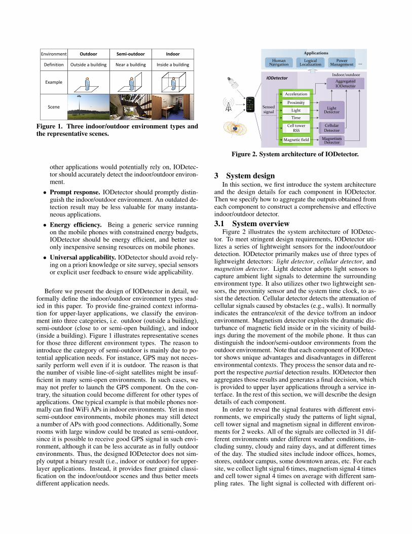
Environment Outdoor Semi-outdoor
Definition Outside a building Near a building
Scene
Indoor
Inside a building
Example
Figure 1. Three indoor/outdoor environment types andthe representative scenes.
other applications would potentially rely on, IODetec-tor should accurately detect the indoor/outdoor environ-ment.
• Prompt response. IODetector should promptly distin-guish the indoor/outdoor environment. An outdated de-tection result may be less valuable for many instanta-neous applications.
• Energy efficiency. Being a generic service runningon the mobile phones with constrained energy budgets,IODetector should be energy efficient, and better useonly inexpensive sensing resources on mobile phones.
• Universal applicability. IODetector should avoid rely-ing on a priori knowledge or site survey, special sensorsor explicit user feedback to ensure wide applicability.
Before we present the design of IODetector in detail, weformally define the indoor/outdoor environment types stud-ied in this paper. To provide fine-grained context informa-tion for upper-layer applications, we classify the environ-ment into three categories, i.e. outdoor (outside a building),semi-outdoor (close to or semi-open building), and indoor(inside a building). Figure 1 illustrates representative scenesfor those three different environment types. The reason tointroduce the category of semi-outdoor is mainly due to po-tential application needs. For instance, GPS may not neces-sarily perform well even if it is outdoor. The reason is thatthe number of visible line-of-sight satellites might be insuf-ficient in many semi-open environments. In such cases, wemay not prefer to launch the GPS component. On the con-trary, the situation could become different for other types ofapplications. One typical example is that mobile phones nor-mally can find WiFi APs in indoor environments. Yet in mostsemi-outdoor environments, mobile phones may still detecta number of APs with good connections. Additionally, Somerooms with large window could be treated as semi-outdoor,since it is possible to receive good GPS signal in such envi-ronment, although it can be less accurate as in fully outdoorenvironments. Thus, the designed IODetector does not sim-ply output a binary result (i.e., indoor or outdoor) for upper-layer applications. Instead, it provides finer grained classi-fication on the indoor/outdoor scenes and thus better meetsdifferent application needs.
Light Detector
Cellular Detector
Magnetism Detector
Aggregated IODetector
IODetectorIndoor/outdoor
Sensed signal
HumanNavigation
LogicalLocalization
PowerManagement
Applications
…
Light
Time
Cell tower RSS
Magnetic field
Acceleration
Proximity
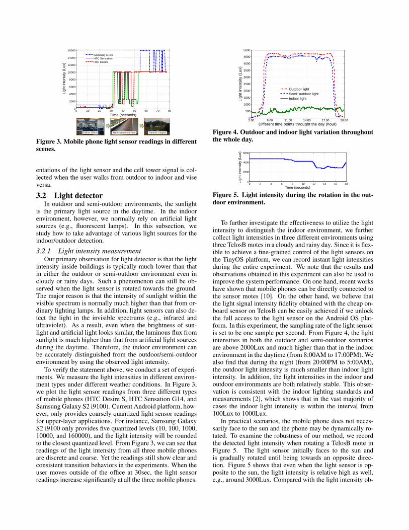
Figure 2. System architecture of IODetector.
3 System designIn this section, we first introduce the system architecture
and the design details for each component in IODetector.Then we specify how to aggregate the outputs obtained fromeach component to construct a comprehensive and effectiveindoor/outdoor detector.3.1 System overview
Figure 2 illustrates the system architecture of IODetec-tor. To meet stringent design requirements, IODetector uti-lizes a series of lightweight sensors for the indoor/outdoordetection. IODetector primarily makes use of three types oflightweight detectors: light detector, cellular detector, andmagnetism detector. Light detector adopts light sensors tocapture ambient light signals to determine the surroundingenvironment type. It also utilizes other two lightweight sen-sors, the proximity sensor and the system time clock, to as-sist the detection. Cellular detector detects the attenuation ofcellular signals caused by obstacles (e.g., walls). It normallyindicates the entrance/exit of the device to/from an indoorenvironment. Magnetism detector exploits the dramatic dis-turbance of magnetic field inside or in the vicinity of build-ings during the movement of the mobile phone. It thus candistinguish the indoor/semi-outdoor environments from theoutdoor environment. Note that each component of IODetec-tor shows unique advantages and disadvantages in differentenvironmental contexts. They process the sensor data and re-port the respective partial detection results. IODetector thenaggregates those results and generates a final decision, whichis provided to upper layer applications through a service in-terface. In the rest of this section, we will describe the designdetails of each component.
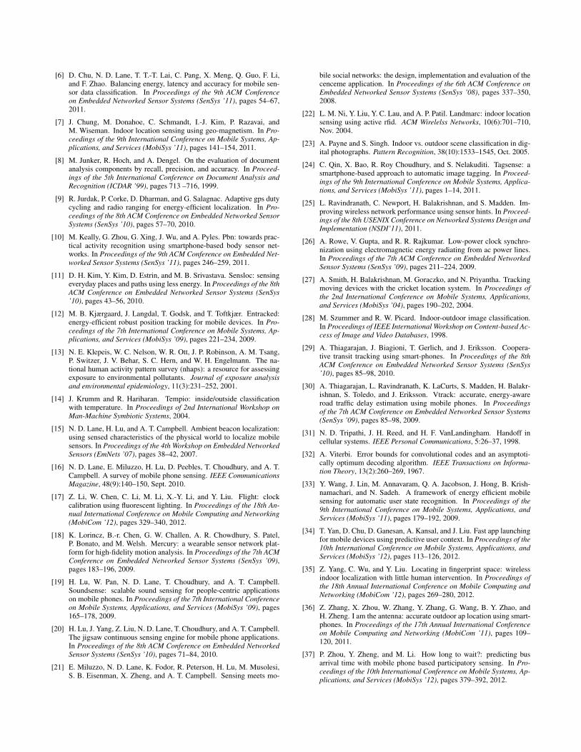
In order to reveal the signal features with different envi-ronments, we empirically study the patterns of light signal,cell tower signal and magnetism signal in different environ-ments for 2 weeks. All of the signals are collected in 31 dif-ferent environments under different weather conditions, in-cluding sunny, cloudy and rainy days, and at different timesof the day. The studied sites include indoor offices, homes,stores, outdoor campus, some downtown areas, etc. For eachsite, we collect light signal 6 times, magnetism signal 4 timesand cell tower signal 4 times on average with different sam-pling rates. The light signal is collected with different ori-
0 10 20 30 40 50 60 70 800
2000
4000
6000
8000
10000
12000
14000
16000
Time (seconds)
Ligh
t int
ensi
ty (L
ux)
Samsung i9100HTC SensationHTC Desire
Indoor office Semi-outdoor corridor Outdoor campus
Figure 3. Mobile phone light sensor readings in differentscenes.
entations of the light sensor and the cell tower signal is col-lected when the user walks from outdoor to indoor and viseversa.
3.2 Light detectorIn outdoor and semi-outdoor environments, the sunlight
is the primary light source in the daytime. In the indoorenvironment, however, we normally rely on artificial lightsources (e.g., fluorescent lamps). In this subsection, westudy how to take advantage of various light sources for theindoor/outdoor detection.
3.2.1 Light intensity measurementOur primary observation for light detector is that the light
intensity inside buildings is typically much lower than thatin either the outdoor or semi-outdoor environment even incloudy or rainy days. Such a phenomenon can still be ob-served when the light sensor is rotated towards the ground.The major reason is that the intensity of sunlight within thevisible spectrum is normally much higher than that from or-dinary lighting lamps. In addition, light sensors can also de-tect the light in the invisible spectrums (e.g., infrared andultraviolet). As a result, even when the brightness of sun-light and artificial light looks similar, the luminous flux fromsunlight is much higher than that from artificial light sourcesduring the daytime. Therefore, the indoor environment canbe accurately distinguished from the outdoor/semi-outdoorenvironment by using the observed light intensity.
To verify the statement above, we conduct a set of experi-ments. We measure the light intensities in different environ-ment types under different weather conditions. In Figure 3,we plot the light sensor readings from three different typesof mobile phones (HTC Desire S, HTC Sensation G14, andSamsung Galaxy S2 i9100). Current Android platform, how-ever, only provides coarsely quantized light sensor readingsfor upper-layer applications. For instance, Samsung GalaxyS2 i9100 only provides five quantized levels (10, 100, 1000,10000, and 160000), and the light intensity will be roundedto the closest quantized level. From Figure 3, we can see thatreadings of the light intensity from all three mobile phonesare discrete and coarse. Yet the readings still show clear andconsistent transition behaviors in the experiments. When theuser moves outside of the office at 30sec, the light sensorreadings increase significantly at all the three mobile phones.
5:00 8:00 11:00 14:00 17:00 20:000
500
1000
1500
2000
2500
3000
3500
4000
4500
5000
Different time points throught the day (hour)
Ligh
t int
ensi
ty (
Lux)
Outdoor lightSemi−outdoor lightIndoor light
Figure 4. Outdoor and indoor light variation throughoutthe whole day.
0 2 4 6 8 10 12 14 16 180
2000
4000
6000
Time (seconds)
Ligh
t int
ensi
ty (
Lux)
Figure 5. Light intensity during the rotation in the out-door environment.
To further investigate the effectiveness to utilize the lightintensity to distinguish the indoor environment, we furthercollect light intensities in three different environments usingthree TelosB motes in a cloudy and rainy day. Since it is flex-ible to achieve a fine-grained control of the light sensors onthe TinyOS platform, we can record instant light intensitiesduring the entire experiment. We note that the results andobservations obtained in this experiment can also be used toimprove the system performance. On one hand, recent workshave shown that mobile phones can be directly connected tothe sensor motes [10]. On the other hand, we believe thatthe light signal intensity fidelity obtained with the cheap on-board sensor on TelosB can be easily achieved if we unlockthe full access to the light sensor on the Android OS plat-form. In this experiment, the sampling rate of the light sensoris set to be one sample per second. From Figure 4, the lightintensities in both the outdoor and semi-outdoor scenariosare above 2000Lux and much higher than that in the indoorenvironment in the daytime (from 8:00AM to 17:00PM). Wealso find that during the night (from 20:00PM to 5:00AM),the outdoor light intensity is much smaller than indoor lightintensity. In addition, the light intensities in the indoor andoutdoor environments are both relatively stable. This obser-vation is consistent with the indoor lighting standards andmeasurements [2], which shows that in the vast majority ofcases the indoor light intensity is within the interval from100Lux to 1000Lux.
In practical scenarios, the mobile phone does not neces-sarily face to the sun and the phone may be dynamically ro-tated. To examine the robustness of our method, we recordthe detected light intensity when rotating a TelosB mote inFigure 5. The light sensor initially faces to the sun andis gradually rotated until being towards an opposite direc-tion. Figure 5 shows that even when the light sensor is op-posite to the sun, the light intensity is relative high as well,e.g., around 3000Lux. Compared with the light intensity ob-

Lightvaluable? Proximity
Light intensity measurement L > σ1 ?
Outdoor/Semi-outdoorIndoor L < σ2 ?
Yes
No
Yes
No
No
YesHigh confidence
Low confidence
Low confidence
Daytime?Yes NoHigh
confidence
Figure 6. Detection flow of light detector.
served in the indoor scenario as shown in Figure 4, we canstill distinguish them easily. Therefore, the detection of thelight intensity is robust to the mobile phone dynamics.3.2.2 Detection process in light detector
Since mobile phones may be placed in pockets or bags,the light sensors may not be always available . We use prox-imity sensors on mobile phones to detect the presence ofnearby objects which may block the light sensor. We as-sociate a confidence level CL ∈ [0,1] for the detection result.Different light signals will lead to different detection confi-dence levels.
Figure 6 summarizes the work flow of the light detectorcomponent. We denote L to be the detected light intensity.The light detector first queries the proximity sensor to checkwhether the light sensor is currently available for accuratedetection. If the light sensor is available, the light intensity Lis then compared with a threshold σ1. If L > σ1, light detec-tor confirms an outdoor/semi-outdoor environment detectionwith a high level confidence CL = 1; if L ≤ σ1, it needs tofurther differentiate whether it is an indoor environment oran outdoor/semi-outdoor environment at night. To this end,light detector refers to the system clock. If the clock indi-cates a daytime, the detector infers the environment to be in-door with a high confidence. If not, light detector comparesL to a threshold σ2. If σ2 < L ≤ σ1, it indicates an indoorenvironment with a confidence level CL = σ1−L
σ1; if L ≤ σ2,
the mobile phone is in an outdoor/semi-outdoor environmentwith a confidence level CL = σ2−L
σ2.
From Figure 4, the sunlight intensity in both daytime andnight is distinguishable from that of indoor lights. Accordingto our empirical study, we set the threshold σ1 to 2000Luxand σ2 to 50Lux.
In addition to the light intensity, we also observe that theindoor fluorescent light powered by the alternating current(AC) power exhibits a periodical pattern. We measure thefrequency of indoor fluorescent light flicker and find that theflicker of indoor fluorescent light intensity is relatively stablein various conditions [17]. This pattern can be further usedto classify indoor/outdoor environment. By using FFT, wecan extract the frequency of light flicker. If the frequencymatches the AC power frequency, it highly indicates an in-door environment. We leave the details of the approach forfuture elaboration due to the page limitation.
Light detector is designed to differentiate the indoor en-vironment from outdoor/semi-outdoor environments. Highlight intensity normally indicates outdoor/semi-outdoor en-
vironments; while extremely low light intensity suggests anindoor environment. The limitation of the light detector isthat the light signal is not always available. In addition, wecannot confidently distinguish the outdoor and semi-outdoorenvironments by merely using light sensors.
3.3 Cellular detectorMobile phones maintain connections to nearby cell tow-
ers to support the primary functionality, i.e., the telephonecalls. The marginal energy consumption of collecting re-ceived cellular signal strength (RSS) is thus negligible. Pre-vious works utilize the information about visible cell towersand their signal strength for localization and tracking [29].Such approaches, however, suffer from low accuracy due tovarious factors. One primary issue is the dividing wall effect,which refers to the fact that the dividing wall significantlyblocks the cellular signal and hence leads to dramatic signalstrength drop when people get into indoor environment. Un-like the localization work where the dividing wall effect isundesired, in this paper, we embrace and exploit the result-ing cellular RSS variations for indoor/outdoor detection.
In this paper, we choose to look at the cell tower signalover other wireless signals (e.g., WiFi) mainly due to the fol-lowing considerations. First of all, cell tower signal is avail-able with no additional energy cost since mobile phones haveto maintain connectivity to cell towers for basic communi-cation, and cellular networks have almost universal cover-age, both outdoor and indoor. Continuous scanning of otherwireless signals (e.g., WiFi), however, consumes much extraenergy and above all, doing so outdoors may lead to unnec-essary energy consumption due to poor signal availability inoutdoor environments. Meanwhile, for those high frequencyband signals like 2.4GHz WiFi signal, because of the shortwavelength, they may severely suffer from the shielding ef-fect of surrounding objects or even the human body itself[36] which will bring in too much noise to the detection sys-tem. On the contrary, the cell tower signal of much longerwavelength can easily diffract around these objects. Thusthe shielding effect of human body is much weaker than thedividing wall effect and will not mislead the system.
3.3.1 Associated cell tower signal strengthWe aim to find the correlation between the RSS variations
of cellular signal and the surrounding environment transi-tions. We first measure the cellular RSS in several repre-sentative places such as offices and homes (indoor), corri-dors and paths in the vicinity of building (semi-outdoor), andplaza and football field (outdoor). We find that the absolutevalue of the cellular RSS provides limited information for thedetection. It varies across different places, times, and phonemodels. In contrast, the RSS variation within a short pe-riod of time normally indicates the context transition. In ourexperiments, we observe a significant variation of the cellu-lar RSS when the ambient environment changes due to theuser mobility. For instance, when the user walks into an of-fice building from the outside, the cellular RSS significantlydrops due to the dividing walls that block the line-of-sightpaths to cell towers. Therefore, we exploit the abrupt vari-ation of the cellular signal strength rather than its absolutevalue to distinguish the indoor/outdoor context that is invari-

0 20 40 60 80 100 120-100
-95
-90
-85
-80
-75
-70
Time (seconds)
Cel
l tow
er R
SS
(dB
m)
Indoor office Semi-outdoor corridor Indoor office
(a) Single cell tower’s RSS variation in environ-mental change.
0 20 40 60 80 100 120−105
−100
−95
−90
−85
−80
−75
−70
−65
−60
−55
Time (seconds)
Cel
l tow
er R
SS
(dB
m)
Celltower 5031Celltower 5093Celltower 5032Celltower 5462
Wc Wc
(b) Multiple cell towers’ RSS variation in envi-ronmental change.
1 2 3 4 5 6 70
20
40
60
80
100
# of cell towers used
Dete
ctio
n p
reci
sion (
%)
(c) Detection accuracy with the varied number ofcell towers.
Figure 7. Cell tower signal strength variation for indoor/outdoor detection.
ant across different places and phone models.To enhance the communication quality, mobile phones
usually connect to the cell tower with the strongest RSS. Fig-ure 7(a) shows the RSS value from the connected cell towerwhen the user walks out to the corridor, and returns backto the office. The user walks outside at 30sec. We can seethat the RSS rises by approximately 15 dB. Then at about90sec, the user comes back to the office and the RSS dropsback within ten seconds. Such a sharp cellular RSS varia-tion can be used to detect the ambient environment changes.On the other hand, since the antenna gain may vary acrossdifferent mobile phone models, it is hard to accurately mapdifferent RSS values to different environments. Adopting theRSS variation can avoid the detection error that would ariseif the absolute RSS value were used, especially when ap-plied on diversified devices and environments. In short, ourcellular detector is independent of mobile phone models andenvironments which ensures the universal applicability.
However, we notice that using RSS information of thesingle associated cell tower suffers from two inherent lim-itations. First, mobile phones may handover from one celltower to another. Such a handover normally introduces asignificant cellular RSS variation. In this case, the RSS vari-ation may not necessarily imply an indoor/outdoor transition.Second, due to the corner effect [31], the cellular RSS maydramatically change in the semi-outdoor environment. Forexample, in Figure 7(a), the RSS suddenly drops by about15 dB at 50sec when the user turns around at a corner. Thecorner effect usually happens in the semi-outdoor environ-ment due to the change of the line-of-sight to cell towers.3.3.2 Visible cell tower signal strength
A mobile phone is normally within the coverage range ofmultiple cell towers and tethers to the one with the strongestsignal strength. Instead of using the single associated celltower, we take a full advantage of all visible cell towers toimprove the detection accuracy [37]. In particular, we mea-sure the signal strengths of all of cell towers and track theirvariations. Thereby we naturally solve the inherent handoverproblem since the cell tower that the phone may connect tois also among the observed cell towers. In addition, with arich set of RSS from multiple cell towers, we can mitigatethe problem of the corner effect. Actually, since the evidentcorner effect usually indicates a semi-outdoor environment,
we can exploit such a property to refine the detection.We denote the RSS from cell tower i at time t as Ri(t),
1 ≤ i ≤ n. We track the RSS variation within a time inter-val ∆, and denote the variation of cell tower i as Vi(t) =Ri(t + ∆)− Ri(t). We refer N+(t) as the number of celltowers whose RSS increases more than ν , i.e., N+(t) =|{i|Vi(t)≥ ν ,0≤ i≤ n}|; we also denote by N−(t) the num-ber of cell towers whose RSS decreases more than ν , i.e.,N−(t) = |{i|Vi(t)≤−ν ,0 ≤ i ≤ n}|. In some cases, we willalso see that N+(t)+N−(t)
n < 1, since the RSS of many cell tow-ers remains quite stable and the differences do not exceed ν .We define N0(t) = n−N+(t)−N−(t) to represent the stabil-ity of cell tower RSS. In our experiments, we set ∆ = 10secand ν = 15dB.
Intuitively, if a user moves from an indoor environmentto an outdoor environment, the RSS of cell towers will in-crease, and vice versa. In addition, the more cell towerswhose RSS exhibits the same trend, the more confident thedetection will be. We correspond the detection results withdifferent confidence levels CC. Say that we find N0(t) = 1,N+(t) = 1, N−(t) = 4, and n = 6, then the cellular detectorwill confirm the ambient environment as the indoor environ-ment with confidence level CC = N−(t)/n = 0.67. The cel-lular detector will also report the confidence level for semi-outdoor/outdoor environment as N+(t)/n = 0.17.
Figure 7(b) illustrates the RSS of multiple cell towerswhen the user walks out to the corridor (at 45sec), and re-turns to the office (at 90sec). In Figure 7(b), we see that theRSS of all four cell towers rapidly climbs up, which impliesthat the user has moved from indoor environment to the out-side. At 90sec, the RSS of all 4 cell towers drops sharply,which means that the user walks back to indoor office. Dur-ing the period from 60sec to 70sec, the RSS of the associatedcell tower varies significantly, while other cell towers remainrelatively stable. In this case, the majority rule helps filterout bursts and reduces detection errors.
We note that the visible cell towers are not necessarilyfrom the same GSM network operator. A phone may de-tect cellular signals from multiple GSM networks which en-sures sufficient number of visible cell towers. In our exper-iment, mobile phones typically see 4∼6 cell towers at onetime. Figure 7(c) plots the detection precision of cellular de-tector with the varying number of cell towers. We find that

0 25 50 75 100 125 150 17520
30
40
50
60
Inte
nsity
(uT)
(a) Ambient magnetic field
0 25 50 75 100 125 150 1750
50
100
150
Time (seconds)
Var
ianc
e
(b) Magnetic field variance
stand still
α
Indoor office Semi-outdoor corridor Outdoor campus
Figure 8. The variation of magnetic field intensity.
the detection precision increases as the number of visible celltower increases and it is satisfactory when the number of celltowers is more than 4. Since mobile phones need to maintainconnections to cell towers, the energy consumption of cellu-lar detector is almost negligible. The major limitation is thatthe cellular detector may perform poorly without sufficientnumber of visible cell towers in some cases.
3.4 Magnetism detectorMany steel structures and electric appliances disturb the
geomagnetic field and generate the electromagnetic fields inthe indoor environment [26]. The disturbance of the Earth’smagnetic field inside buildings can be utilized as fingerprintsfor the indoor localization [7]. However, such a localizationapproach requires a labor-intensive fingerprinting and can-not be applied for the indoor/outdoor detection directly. Inthis section, we seek to explore useful characteristics of themagnetic fields in different ambient environments that mayhelp to enhance the indoor/outdoor detection.
The magnetic field exhibits distinct patterns in in-door/outdoor environments. In the indoor environment, theEarth’s geomagnetic field varies at different positions due tothe disturbance of steel structures and electric appliances in-side buildings. For instance, the intensity of the magneticfield near the equator and near the pole varies from 0.25 to0.65gauss ( i.e., 25 to 65µT ). In comparison, a strong refrig-erator magnet has a field of around 100 gauss (two orders ofmagnitude higher) [1]. Therefore, the intensity of magneticfields shows a high variance across different places near andinside buildings than that in the open space.
Figure 8 plots the magnetic field intensity and its vari-ance in an example scenario in which a user walks outside ofthe office, passing through a corridor. In particular, the userwalks from 0sec to 25sec, stops walking from 25sec to 50secinside the building, and then walks along the corridor from50sec to 100sec. In the end, the user walks along the road. InFigure 8(a), we find that the intensity of magnetic field in theindoor environment varies dramatically. Figure 8(b) plots thevariance averaged over τ seconds to filter out noises. We findthat the variance is very high when the user moves (from 0secto 25sec). When the user is walking through the corridor, themagnetic field intensity also shows significant variance. Incontrary, after the user comes outside after 100sec, the vari-
ance drops significantly. Therefore, by choosing a suitablethreshold α , we could distinguish the indoor/semi-outdoorfrom the outdoor environment.
We vary the threshold α from 0 to 40 with step length 2and statistically analyze the detection accuracy using the col-lected data described in §3.1. If the threshold is small, mostindoor/semi-outdoor environments will be correctly classi-fied, while many outdoor environments will be wrongly de-tected as the indoor/semi-outdoor environment. On the otherhand, if the threshold is too large, most outdoor environ-ments will be correctly classified but we will miss the detec-tion of many indoor/semi-outdoor environments. Therefore,we select an empirical threshold 18 to achieve a balance. Inour implementation, we first refer to accelerometer to detectwhether the mobile phone is moving. If so, magnetism detec-tor samples the magnetism sensor, and uses the variance av-eraged over τ = 10 seconds to detect the environment. Whenthe user stops walking (from 25sec to 50sec) the variance be-comes very small. When the user is moving, we confirm thedetection of an indoor/semi-outdoor environment if the fieldvariance is larger than α; otherwise the detection result is anoutdoor environment. Since a larger τ yields a higher de-tection robustness, we set the confidence level of magnetismdetector CM = τ/10.3.5 Aggregated IODetector
Each of the three detectors shows unique advantages anddisadvantages. They best fit different scenarios. For in-stance, the light detector can rapidly detect the ambient en-vironment. The light detector, however, requires the mo-bile phone to be exposed in the space. If the phone is in-side pocket or bags, the light detector cannot provide accu-rate detection results. The cellular detector needs sufficientcell tower coverage to confidently detect the ambient context.The detection response is also slower. The magnetism detec-tor is only available when the user is moving around such thatthe magnetic disturbance inside buildings can be exploited.We call the three individual detectors as sub-detectors andintegrate them so as to output an arbitrated decision.
At first, we directly aggregate the instant detection resultsof all three sub-detectors. We let each sub-detector reporta detection profile, i.e., a triplet of confidence levels for thethree possible environment types, and sum the confidencelevels from all three sub-detectors. The environment typewith the highest summed confidence level will be output asthe final detection result. Such a combination makes statelessdecision, i.e., the detection output is solely determined by thecurrent environment status and the instant sensor readings.We call it stateless IODetector in the following.
Figure 9 shows the aggregation processing of statelessIODetector. We denote the detection profile from the threesub-detectors as [DL(t),CL(t)] (light), [DC(t),CC(t)] (cellu-lar), and [DM(t),CM(t)] (magnetism), where D is the outputdetection result from each sub-detector and C is the set of as-sociated confidence levels for the three possible environmenttypes. As described in §3, each individual sub-detector out-puts the possible environment types and associate confidencelevels for them. For example, each detection profile of lightdetector can be denoted as [DL,CL] = {(indoor, CL,indoor),(semi-outdoor, CL,semi−outdoor), (outdoor, CL,outdoor)}. For

Light
[DL, CL] [DC, CC] [DM, CM]
Time CellularProximity Magnetism
Outdoor Semi‐outdoor Indoor
Coutdoor Csemi‐outdoor Cindoor
Figure 9. Stateless IODetector.
each possible environment type, we sum the confidence lev-els from the three sub-detectors and obtain the triplet of over-all confidence levels CE ∈ {Cindoor,Csemi−outdoor,Coutdoor}.The environment type with the highest overall confidencelevel will be reported as the final detection result.
The stateless IODetector provides us instant detection re-sults. Users can activate IODetector on need basis. Thusthe significant out-of-the-box functionality ensures the en-ergy efficiency of stateless IODetector. In our experiments,however, we find that the current environment state of hu-man being is usually related to the previous state. For exam-ple, during the movement from indoor to outdoor, the userhas a good chance experiencing the semi-outdoor environ-ment. The stateless IODetector does not consider previousstates and thus may suffer from noises. In the following, wealternatively consider a stateful integration of the three sub-detectors which makes decisions on top of both current andprevious observations.
In order to do so, we let all sub-detectors continuouslyperform detection and return sequential results. Figure 10sketches an illustrative example of stateful IODetector. Wemake use of the Hidden Markov Model (HMM) [30] tointegrate the sub-detectors. The HMM models a Markovprocess with underlying hidden states. Every hidden stateemits observable states with particular conditional probabil-ity distribution called the emission probability distribution.The HMM traverses the states and the transitions amongthe hidden states are governed by the transition probabili-ties. With the HMM, we estimate the most likely sequenceof hidden states that may produce the sequence of observ-able states. We use the first-order HMM in which the cur-rent environment state is only affected by the immediate pre-vious state. We denote the hidden state at time t as H(t)∈ {indoor, semi-outdoor, outdoor} and the observed resultsfrom the three sub-detectors as RL(t)(light), RC(t)(cellular),and RM(t)(magnetism), where R is the output environmenttype with the highest confidence level from each individualsub-detector. For example, the detection result from lightdetector is RL ∈{indoor, semi-outdoor/outdoor}. IODe-tector incorporates the detection results from all the sub-detectors and treats them as the observable state B(t) =[RL(t),RC(t),RM(t)]. IODetector will thus infer the mostlikely hidden state H(t) from the previous hidden stateH(t−1) and the current observable state B(t). The transition
Hidden states
Observable states
Light
RL RC RM
Time CellularProximity Magnetism
Figure 10. Stateful IODetector.
and emission probabilities determine the inference result.Transition probability. We determine the transition
probabilities based on the experimental observations and thecharacteristics of IODetector. Since the detection period ofIODetector is set to 10 seconds, when a user is previouslyindoor, the current environment state is highly likely indoorand might be semi-outdoor but is not likely outdoor becausethe user unlikely moves directly from indoor to fully outdoorenvironment. It is similar when a user is outdoor. When theuser is semi-outdoor, however, he could be able to directlymove indoor or outdoor, or he may stay semi-outdoor. Wedenote the transition probability from environment H1 to H2(elaborated as I:indoor, O:outdoor, and S:semi-outdoor inthe following) as T (H1,H2). Based on above observations,we determine the transition probabilities as follows:
1) T (S, I) = T (S,S) = T (S,O) = p1 = 1/3.2) T (I, I) = T (I,S) = p2 = 1/2.3) T (O,O) = T (O,S) = p3 = 1/2.4) T (O, I) = T (I,O) = p4 = 0.Emission probability. The emission probability E(B,H)
is the likelihood that an observable state B is observed inH environment. We set the emission probability accordingto the training data as described in §3.1. Table 1 showsthe emission probability of each hidden state (indoor, semi-outdoor and outdoor) to each observable state in detail.
Viterbi algorithm. We apply the Viterbi algorithm [32], adynamic programming algorithm, to estimate the most likelyenvironment type in the HMM according to the detection re-sults of the three sub-detectors. As the scales of both hid-den and observable states are small, the computation costcan be easily accommodated on commodity mobile phoneplatforms.
For the stateful IODetector, we do not keep all the sensorson. We use the accelerometer as a trigger. Only when the ac-celerometer detects the user movement, IODetector activatesthe sensors and starts to infer the new environment state fromthe HMM. When the user is stationary, the user environmentstate is deemed unchanged and all sensors are deactivated,and so is the HMM processing.
Applying the HMM, stateful IODetector further exploresthe sequential observations and provides stateful detectionresults, which are robust to noisy measurements [30]. Itsdetection accuracy, which we show in §4.2.2, is better thanstateless IODetector. However, stateful IODetector may con-

Detector Observablestate Indoor Semi-
outdoor Outdoor
Light Indoor 0.9 0.11 0.11detector Semi/outdoor 0.1 0.89 0.89Cellular Indoor 0.82 0.16 0.16detector Semi/outdoor 0.18 0.84 0.84
Magnetism Semi/indoor 0.88 0.88 0.17detector Outdoor 0.12 0.12 0.83
Table 1. Emission probability settings.
sume extra energy since it has to perform continuous de-tection. We show the energy consumption of IODetectorin §4.2.2 and §4.3.3. Users can choose either stateless orstateful IODetector which is more suitable for the applica-tion scenarios.4 Evaluation
We implement a prototype system on the Android plat-form with different types of mobile phones. We collect sen-sor data at 19 traces including 84 different sites over a one-month period of experiments. The following details the ex-periment methodology and the results.4.1 Experimental methodology
Mobile Phones. We implement IODetector on the An-droid platform and test its performance using three differ-ent types of mobile phones (Samsung Galaxy S2 i9100,HTC Desire S, and HTC Sensation G14). All types of mo-bile phones are equipped with light sensors, proximity sen-sors, magnetism sensors, accelerometers, etc. The SamsungGalaxy S2 i9100 has a 1 GB RAM and dual-core 1.2 GHzCortex-A9 processor, the HTC Desire S has a 768 MB RAMand 1 GHz Scorpion processor, and the HTC Sensation G14has a 768 MB RAM and dual-core 1.2 GHz Scorpion proces-sor. As IODetector is independent of platforms, we believethat the proposed indoor/outdoor detection method can besimply implanted to other mobile computing platforms, suchas Apple iOS and Windows Phone.
Sensor motes. We use TelosB motes integrated with lightsensors to measure the light signals with higher fidelity. Wemodify TinyOS code to directly read the voltage on the lightsensor S1087-01. The sensitivity range of the light sensoris from 300nm to 1200nm with a full coverage of the visi-ble light spectrum and a partial coverage of the infrared andultraviolet spectrum. At the current stage, we connect theTelosB mote to the mobile phone for the enhanced light fi-delity, and we look forward to a similar performance solelyusing the mobile phones if we unlock the full access to theon-board light sensors on the Android OS platform.
Experiment environment. We experiment with 19different walking traces and collect sensor readings from23 outdoor segments (covering football fields, downtownsquares, etc.), 27 semi-outdoor segments (covering corridorsand paths near buildings), and 34 indoor segments (includingoffices and shopping malls) mainly in campus and city areas(summarized in Table 2) during the period 5:00 to 22:00 in30 days with different weather conditions. The users walkalong these traces and the mobile phones perform continuousdetection for the experimental sites along the traces. Thesesites are different from the environments where we collectprior data and learn the IODetector philosophy.
Environment type Representative places Total
Outdoor 12 campus sites,11 downtown areas 23
Semi-outdoor 15 campus sites,12 downtown areas 27
Indoor 10 office rooms, 18 stores,6 restaurants 34
Table 2. Experimental sites
IN SEMI/OUT0
20
40
60
80
100IN
(a) Light detctor
Det
ectio
n ra
tio (
%)
IN SEMI/OUT0
20
40
60
80
100SEMI / OUT
IN SEMI/OUT0
20
40
60
80
100
(b) Cellular detector
IN
IN SEMI/OUT0
20
40
60
80
100SEMI / OUT
IN/SEMI OUT0
20
40
60
80
100
(c)Magnetism detector
IN / SEMI
IN/SEMI OUT0
20
40
60
80
100OUT
Figure 11. Detection performance of three sub-detectors.
4.2 System performanceIn this section we show the detection performance of
the three individual sub-detectors as well as the aggregatedIODetector. We also compare the performance of the state-less and stateful IODetectors.
4.2.1 Performance of sub-detectorsOne may query three different detectors independently
and select an arbitrary one in practice. To evaluate the contri-bution of each detector (i.e., light detector, cellular detector,and magnetism detector), we examine the detection perfor-mance independently in Figure 11. Each detector reports theenvironment type with the highest confidence level after thelocal computation.
The light detector is available when there are clear pathsbetween mobile phones and ambient light sources. Figure11(a) depicts the detection performance of light detector. Wefind that the light detector can effectively distinguish the in-door environment from the semi-outdoor/outdoor environ-ment. In Figure 11(a), when mobile phones are in the indoorenvironment, the detection accuracy is around 83%. Whenthe phones are in the semi-outdoor/outdoor environment, thedetection accuracy is around 88%. Figure 11(b) shows thedetection performance of cellular detector that classifies theindoor environment from the semi-outdoor/outdoor environ-ment. We obtain quite a close performance of cellular de-tector compared with that of light detector. Our experimentsmainly cover the campus and city areas where most sites arecovered by at least 5 cell towers. In such experiment settings,the cell tower based detection performs with 82% accuracy.
We note that both light detector and cellular detectorcan effectively classify the indoor environment from thesemi-outdoor/outdoor environment. On the other hand, themagnetism detector can enhance the detection capability ofIODetector in classifying the semi-outdoor and outdoor en-vironment. Figure 11(c) plots the performance of the mag-netism detector. The magnetism detector can successfullydistinguish the indoor and semi-outdoor environments fromthe outdoor environment with an accuracy around 80%.

indoor semi−outdoor outdoor0
20
40
60
80
100
Environment types
Det
ectio
n ra
tio (%
)(a) Detection precision
indoor semi−outdoor outdoor0
20
40
60
80
100(b) Detection recall
Stateful IODetectorStateless IOdetector
Stateful IODetectorStateless IODetector
Figure 12. Detection precision and recall of statelessIODetector and stateful IODetector.
4.2.2 Performance of aggregated IODetectorAs described in §3.5, there are two approaches to con-
structively combine the results from the three sub-detectors.Detection accuracy. In Figure 12, we show the detec-
tion accuracy of both stateless and stateful IODetectors. Wereport the average detection results, including detection pre-cision and recall [8], in different scenarios.
As shown in Figure 12, the overall detection accuracyof stateless IODetector is about 82%. When the three sub-detectors are aggregated as the stateful IODetector, there isimprovement of detection accuracy for all different types ofindoor/outdoor environments but not much. According tothe experiment results, for both stateless and stateful IODe-tectors, the detection precision and the recall for the indoordetection are slightly higher than the detection results for theother two environment types. Nevertheless, compared withless than 83% detection accuracy of individual detectors, inthe aggregated IODetector both the precision and the recallare consistently above 88% (90%+ for the indoor environ-ment). The experiment results suggest that IODetector ac-curately classifies the indoor/outdoor environments for mostcases. For the stateful IODetector, with the optimization ofthe HMM parameters, the detection accuracy could be fur-ther improved.
In Figure 13, we show one of the walking traces in thatwe experiment with in NTU campus. The experiment wasdone in a rainy day. The detection results from stateless andstateful IODetectors can be seen in Figure 13(bottom). Thedetection results of both IODetectors are accurate. Whenwe look at their detection results separately, there are somedifferences. In some segments, the stateless IODetector suf-fers from mis-detection of some semi-outdoor environments,which are usually in the trace between indoor and outdoorenvironments. In some segments, although the ambient envi-ronment is not changed, the detection result of statless IODe-tector may vary. The detection result of stateful IODetec-tor is relatively more stable due to the effect of the HMM.Considering the previous state, the HMM filters out somenoise and avoids the mis-detection of semi-outdoor environ-ments during user movements. However, the stateful IODe-tector may give inaccurate results for frequent environmentchanges as it reacts insensitively to the sudden change of en-vironment types and there are extra energy consumptions forstateful IODetector due to its continuous operation.
Semi-outdoorIndoor
Outdoor
Ground truth
StatelessStateful
50 m200 ft
Figure 13. An experiment trace in the university campus.
Sensors Samsungi9100
HTCDesire
HTCSensation
No sensor 18.3 15.4 18.1Magnetism 2Hz 18.0 14.9 17.8
Light 400Hz+FFT 17.8 15.0 17.5Celltower 2Hz 18.1 15.1 17.9
Table 3. Battery duration for different sensor settings (inhours).
Detection latency. The detection latency of IODetector isbounded by the time consumed by three sub-detectors. Thelight detector is fast, sampling at 400 Hz that is sufficient tocapture the alternating light intensity. We set the same detec-tion window length of 10 seconds for both cellular detectorand magnetism detector. Considering that three detectors canrun in parallel, it typically takes 10 seconds to warm up andthen starts reporting detection results. After that, IODetectorcan keep tracking the indoor/outdoor transitions according tothe application requirements.
System overhead. We measure the energy consumptionof continuously sampling light sensor, magnetism sensor andcellular signals. We measure the battery duration with thescreen set to the minimum brightness in the experiments. Ta-ble 3 shows the measured battery lifetime when the mobilephones continuously sample different sensors. In Table 3, wefind that the battery durations for sampling magnetism sen-sor at 2Hz and sampling light sensor at 400Hz with the FFTare quite close to the battery duration without sampling anysensors. Sampling the cellular signal consumes little extrabattery power as well. Thus although the stateful IODetec-tor needs to perform continuous detection, the low energyconsumption makes it affordable for the users.
4.3 Case study: inferring GPS availabilityIn this subsection, we conduct a case study and demon-
strate how IODetector can be used to provide indicative in-formation on the GPS availability. Nowadays, many smart-phones are equipped with commodity GPS modules that pro-vide localization and navigation services for mobile applica-tions. Traditional works [30] study how to adaptively useGPS/GSM/WiFi signals for energy-efficient localization ortracking. Such approaches, however, either assume the pre-knowledge of the ambient environment, or infer it passivelywith high overhead and low efficiency. Serving as a genericand lightweight service, IODetector can be used to providecheap and instant triggers for switching on/off the GPS com-ponent so as to achieve both high location accuracy and en-ergy efficiency.

Semi-outdoorIndoor
50 m200 ft
Outdoor
A
I
H
G
FE
D
C
B
J
KL
M
N
OP
QR
S
(a) GPS experiment trace in the uni-versity campus.
indoor semi−outdooroutdoor0
2
4
6
8
10
12
14
Sat
ellit
es
(a) Number of satellites
indoor semi−outdooroutdoor0
10
20
30
40
50
SN
R
(b) Signal to noise ratio
(b) Number of visible satellites and SNR of GPS signals indifferent environments.
1 2 3 4 5 6 7 8 9 100
20
40
60
80
100
120
140
Not available
Number of available satellites
Err
or (
met
ers)
(c) GPS accuracy for different number of avail-able satellites.
Figure 14. Indoor/outdoor dependent GPS performance.
4.3.1 Indoor/outdoor dependent performanceFor accurate localization, GPS normally needs more than
4 clear line-of-sight paths to GPS satellites. In the outdoorenvironment, with a sufficient number of paths to satellites,commodity GPS modules can achieve a localization accu-racy within 20m. In the shadow of tall buildings, some line-of-sight paths to satellites would be blocked and GPS mayonly receive signals from a small number of satellites. Somereceived GPS signals might be from the reflecting walls lead-ing to the multi-path problem. In such scenarios, the local-ization accuracy degrades dramatically. In the indoor envi-ronment, there is normally no line-of-sight path to satellites.As a result, GPS takes minutes to scan the satellites withoutfinding any strong signals from satellites and the localizationerror can be up to 400m. In addition to the inaccuracy, itusually causes high responsive latency and extra power con-sumption. As the GPS performance differs significantly inthe indoor and outdoor environments, mobile phones greatlybenefit from a priori knowledge of the ambient environmenttypes with minimal overhead.
4.3.2 GPS availability and localization accuracyWe evaluate the localization accuracy and energy con-
sumption of a mobile phone GPS component along with awalking path in our experiment. Figure 14(a) plots the ex-periment path in our campus. We mark the route segmentsfrom A to S. The total length of the walking path is approxi-mately 1600m, with 620m outdoor, 380m semi-outdoor, and600m indoor segments, respectively. We query GPS for lo-cation information when we travel along the circular pathwith different mobile phone models under different weatherconditions during the one-month experiments.
Figure 14(b) plots the number of visible satellites as wellas the SNR (signal to noise ratio) of the GPS signals inthe indoor, semi-outdoor, and outdoor environments, respec-tively. In Figure 14(b)(left), we find that in the indoor en-vironment the mobile phones normally receive less than 2GPS signals, though the mobile phones can sometimes cap-ture slightly more GPS signals near windows. In the out-door environment, the phones normally receive signals frommore than 6 GPS satellites even in cloudy and rainy days.The number of observed satellites varies in between in thesemi-outdoor environment (e.g., corridors and paths in theshadow of buildings). Figure 14(b)(right) plots the SNR ofthe received GPS signals. The SNR value is a normalized
value from the android API indicating the signal to noise ra-tio of the received satellite signal. The SNR greater than20 is usually high enough for the mobile phone to calculateaccurate location, and typically, the greater, the better. InFigure 14(b)(right), we observe that in the indoor environ-ment the SNR of the GPS signals vary from 0 to 10. In theoutdoor environment, the SNR becomes much higher vary-ing from 25 to 42 due to the clear line-of-sight paths betweenthe phones and GPS satellites. In the semi-outdoor environ-ment, although we may sometimes observe more than 4 GPSsignals, typically the SNR of GPS signals is not high enoughto ensure accurate localization.
Figure 14(c) plots the summarized GPS localization erroragainst the number of visible satellites. We find that the GPSmodules can obtain more accurate localization results withmore visible satellites. According to the experiment results,with less than 4 visible satellites GPS service is generally un-available. The GPS module is able to work with more than 4visible satellites. However, even with 4 satellite signals, thelocalization accuracy vary dramatically in our experiment.With more than 6 visible satellites, the localization error isaround 20m. We also observe that more visible satellites(e.g., >9) yield less marginal improvements in the localiza-tion accuracy. With 10 GPS satellites, the localization errorcan be within 10m.
In summary, the experiment results demonstrate that theGPS availability and localization accuracy are highly corre-lated to the environment types. Yet solely reading such avail-ability from the GPS module itself can be up to minutes andconsume much extra energy in scanning the satellites.
4.3.3 IODetector-augmented GPS: IO-GPSWe can simply leverage IODetector to infer the GPS with
accurate indoor/outdoor awareness. In our IOdetector aug-mented GPS (IO-GPS) scheme, mobile applications invokeIODetector for the indoor/outdoor detection before switch-ing on the GPS module. If the mobile phone is outdoor,the applications can confidently call GPS for an outdoor lo-calization; if it is indoor, the applications may postpone theGPS localization and resort to a variety of alternative indoorlocalization techniques [35]. In this experiment, We trackthe localization accuracy and energy consumption of the tra-ditional GPS and the IO-GPS scheme.
IO-GPS localization accuracy. We follow the path inFigure 14(a) at a walking speed and collect the GPS local-

0 10 20 300
100
200
300
400
500
Time (mins)
Erro
r (m
eter
s) A B C D E I L N QF G J RO P SH K M
Semi-outdoorOutdoor Indoor
Ground truthIODetector
Figure 15. GPS localization accuracy of an example instance along the walking path.
0 50 100 150 200 250 300 350 4000
0.1
0.2
0.3
0.4
0.5
0.6
0.7
0.8
0.9
1
Error (meters)
CD
F
OutdoorSemi−outdoorIndoorOverall
Figure 16. CDF of localization error.
ization data. We repeat the experiment 10 times and reportthe average results. We use stateful IODetector to estimatethe environment type. Figure 15 presents one example in-stance. In Figure 15, we observe that the GPS localizationerror varies across different path segments. We see apparentvariation on GPS localization error due to the indoor/outdoorenvironment transition. For example, when we move fromsegment G to H (indoor → outdoor), we see a big dive ofthe localization error; when we move from P to Q then to R(outdoor→ semi-outdoor→ indoor), we observe a two-stagejump of the localization error. Consistent with the abovemeasurement, in the indoor environment the GPS localiza-tion error is much larger than that in the semi-outdoor oroutdoor environment. The path segment J has a particularlyhigh error because the segment is underground and the GPScomponent detects almost no satellite signals.
Figure 16 summarizes the localization error from the 10experiments and we take a fine-look at the localization er-ror in outdoor, semi-outdoor, and indoor areas, respectively.The median localization error in the outdoor environment isaround 24m with the maximum error within 50m in our ex-periments. In the semi-outdoor areas, the median error isaround 44m while the 90th percentile can be up to 100m.In the indoor environment, the median localization error isaround 140m with the 90th percentile of 235m. The overalllocalization error presents the performance of the traditionalGPS. We find that the median localization error is around55m with a long tail up to 400m. In our experiment set-ting, users walk around campus with comparable route seg-ments inside buildings and outdoor environments. Yet theresearches on human activity pattern show that people spendaround 89% of the time in the indoor environment [13].
Without discriminating the indoor/outdoor environment,
Environment Samsungi9100
HTCDesire
HTCSensation
Indoor GPS 9.2 6.6 8.7Semi-outdoor GPS 9.8 7.2 9.7
Outdoor GPS 10.1 7.3 9.8Stateful IODetector 17.3 14.4 16.8
Table 4. Battery consumption comparison (in hours).
blindly using the traditional GPS scheme would performsimilarly to that in the indoor cases for most of the time.Augmented by IODetector, the IO-GPS performance wouldbe closer to that in the outdoor/semi-outdoor environment.In Figure 15(bottom), we compare the indoor/outdoor detec-tion results with the ground truth along the experiment path.We can see that IODetector provides promising detection ac-curacy. In particular, IODetector successfully detects the in-door cases from the semi-outdoor and outdoor cases. Foroutdoor/semi-outdoor detection at some places, IODetectorcannot provide the most accurate result. We revisit the placessuch as the path segments D and E, where IODetector mis-classifies the semi-outdoor and outdoor environments. Wefind that D and E are located at a corner passing by a two-storey building. It is even difficult to manually label suchplaces as ground truth, yet we believe the misclassificationresults of IODetector in such corner cases would introducelittle influence to the GPS localization service.
Energy consumption. We measure the power consump-tion when we run the GPS module during the experiment.We measure the battery life with the screen set to the min-imum brightness. Table 4 summarizes the battery life ofthree different mobile phone models in different environ-ments. We also present the battery duration for running state-ful IODetector for the indoor/outdoor detection. In Table4, the first 3 rows show the energy consumption of mobilephones when GPS is turned on for indoor, semi-outdoor andoutdoor environments. We find that GPS drains the batteryrapidly in all the environments. The energy consumptionof GPS is especially high in the indoor environment wherethe GPS module continuously scans the satellite signals andrapidly depletes the battery energy. With the awareness ofthe indoor/outdoor environment, IO-GPS may avoid unnec-essarily switching on the GPS module and save the energyconsumption in the indoor environment.
5 Related workThough there have not yet been generic approaches pro-
posed for explicit indoor/outdoor detection, there exist a

wide body of related works that implicitly deal with sucha problem.
Environment detection. GPS lock status can be used toindirectly infer the ambient environment [25], but it usuallyincurs substantial energy cost and high latency. ABL [15]proposes the approach that allows mobile sensors to localizethemselves by exploiting their ambient physical environmentsignals. FLIGHT [17] explores the fact that the light inten-sity changes with a stable period in the indoor environmentand uses the feature to perform clock calibration. TempIO[14] classifies the ambient environment by comparing the en-vironment temperature with the current outdoor temperaturethrough the network query. Yet temperature sensors are notwidely available on current mobile phones. Along with manyother sensing recourses, the temperature sensor if availableon mobile phones can be used to complement our work.TagSense [24] classifies the ambient environments to auto-matically annotate images during the picture-click. Someworks in image processing and pattern recognition [23, 28]also study the problem of classifying images according toambient environments. Those works can provide partial in-dication on indoor/outdoor environment. As taking photosnormally incurs substantial human effort and energy cost,we can hardly rely on such classification approaches to buildgeneric and automatic indoor/outdoor detection service.
Localization and tracking. Many works study GPS/GSM/WiFi localization schemes. StarTrack [3] provides acomprehensive set of APIs for the development of mobilelocalization and tracking applications. Zhou et al. [37] usecell tower sequences to track the buses and make bus arrivaltime prediction for the waiting passengers. LANDMARC[22] proposes a location sensing prototype system that usesRFID technology for locating objects inside buildings. En-Tracked [12] focuses on outdoor pedestrian tracking usinglightweight accelerometer to trigger GPS to reduce powerconsumption. Jurdak et al. [9] complement GPS duty cy-cling with short-range radio contacts to balance position-ing accuracy and energy consumption. VTrack [30] stud-ies reducing energy consumption using inaccurate WiFi po-sitioning schemes to measure road traffic condition. Chunget al. [7] present an accurate positioning system based onthe magnetic signatures in the indoor environment. Aboveapproaches primarily focus on obtaining accurate physicallocations and track the targeted objects. They can poten-tially benefit from the indoor/outdoor awareness of IODe-tector, e.g., adaptively switching on/off the GPS modules inlocalization.
Context awareness and activity recognition. A numberof works have studied use of sensors to recognize user activ-ities and detect ambient context. Yan et al. [34] design andbuild FALCON to remedy slow app launch using contexts topredict the next app to launch. CenceMe [21] exploits sen-sors on mobile phones to automatically infer people’s ambi-ent context and then allows users to share that through so-cial networks. Mercury [18] monitors patients using wear-able sensors in indoor medical environments. EEMSS [33]presents an energy efficient sensor management frameworkwhich uses minimum number of sensors on mobile devicesto monitor user status. Jigsaw [20] supports continuous sens-
ing applications on mobile phones to infer human activi-ties and ambient context. PBN [10] proposes user activitydetection system using sensors on both mobile phones andon-body wireless sensors. Such works either implicitly as-sume the activity context or passively infer the ambient con-text. Unlike those works, our work proactively detects theindoor/outdoor environment using various lightweight sen-sors (e.g., light sensor, cellular signal, and magnetism sen-sor) without any remote supports.
SoundSense [19] classifies general sound types (e.g., mu-sic, voice) to achieve context recognition. SensLoc [11] col-lects WiFi beacons to extract useful patterns to infer con-textual information. Kobe [6] aids the mobile classifier de-velopment by automatically extracting high-level semanticsfrom raw sensory data while balancing energy, latency andaccuracy. Our work primarily differs from them in thatIODetector instantly detects the primitive ambient contextwithout any labor-intensive site survey and user feedback.Those works may benefit from IODetector by taking theindoor/outdoor information as a primary filter for contextrecognition.
6 ConclusionsWe present the design and implementation of an in-
door/outdoor environment detection system, which effi-ciently takes input from a variety of lightweight sensors toderive the indoor/outdoor information. By intelligently ag-gregating the sub-detectors, IODetector achieves prompt andaccurate detection results in various time and environments.We comprehensively test IODetector through a prototype im-plementation and evaluate the system based on different An-droid mobile phone models. We particularly conduct a casestudy where we make use of IODetector results to infer theGPS availability and accuracy under various indoor/outdoorenvironment.
7 AcknowledgementWe would like to thank our shepherd, Deepak Ganesan, as
well as the anonymous reviewers for providing constructivefeedbacks and valuable input for improving the quality ofthis paper. We acknowledge the support from NTU NanyangAssistant Professorship (NAP) grant M4080738.020 and Mi-crosoft research grant FY12-RES-THEME-001.
References[1] Earth magnetic field. http://en.wikipedia.org/wiki/Earth_
magnetic_field.
[2] Lux. http://en.wikipedia.org/wiki/Lux.
[3] G. Ananthanarayanan, M. Haridasan, I. Mohomed, D. Terry, and C. A.Thekkath. Startrack: a framework for enabling track-based applica-tions. In Proceedings of the 7th International Conference on MobileSystems, Applications, and Services (MobiSys ’09), pages 207–220,2009.
[4] M. Azizyan, I. Constandache, and R. Roy Choudhury. Surroundsense:mobile phone localization via ambience fingerprinting. In Proceed-ings of the 15th Annual International Conference on Mobile Comput-ing and Networking (MobiCom ’09), pages 261–272, 2009.
[5] P. Bahl and V. N. Padmanabhan. RADAR: an in-building RF-baseduser location and tracking system. In Proceedings of the 19th IEEEInternational Conference on Computer Communicaitons (INFOCOM’00), pages 775–784, 2000.
[6] D. Chu, N. D. Lane, T. T.-T. Lai, C. Pang, X. Meng, Q. Guo, F. Li,and F. Zhao. Balancing energy, latency and accuracy for mobile sen-sor data classification. In Proceedings of the 9th ACM Conferenceon Embedded Networked Sensor Systems (SenSys ’11), pages 54–67,2011.
[7] J. Chung, M. Donahoe, C. Schmandt, I.-J. Kim, P. Razavai, andM. Wiseman. Indoor location sensing using geo-magnetism. In Pro-ceedings of the 9th International Conference on Mobile Systems, Ap-plications, and Services (MobiSys ’11), pages 141–154, 2011.
[8] M. Junker, R. Hoch, and A. Dengel. On the evaluation of documentanalysis components by recall, precision, and accuracy. In Proceed-ings of the 5th International Conference on Document Analysis andRecognition (ICDAR ’99), pages 713 –716, 1999.
[9] R. Jurdak, P. Corke, D. Dharman, and G. Salagnac. Adaptive gps dutycycling and radio ranging for energy-efficient localization. In Pro-ceedings of the 8th ACM Conference on Embedded Networked SensorSystems (SenSys ’10), pages 57–70, 2010.
[10] M. Keally, G. Zhou, G. Xing, J. Wu, and A. Pyles. Pbn: towards prac-tical activity recognition using smartphone-based body sensor net-works. In Proceedings of the 9th ACM Conference on Embedded Net-worked Sensor Systems (SenSys ’11), pages 246–259, 2011.
[11] D. H. Kim, Y. Kim, D. Estrin, and M. B. Srivastava. Sensloc: sensingeveryday places and paths using less energy. In Proceedings of the 8thACM Conference on Embedded Networked Sensor Systems (SenSys’10), pages 43–56, 2010.
[12] M. B. Kjærgaard, J. Langdal, T. Godsk, and T. Toftkjær. Entracked:energy-efficient robust position tracking for mobile devices. In Pro-ceedings of the 7th International Conference on Mobile Systems, Ap-plications, and Services (MobiSys ’09), pages 221–234, 2009.
[13] N. E. Klepeis, W. C. Nelson, W. R. Ott, J. P. Robinson, A. M. Tsang,P. Switzer, J. V. Behar, S. C. Hern, and W. H. Engelmann. The na-tional human activity pattern survey (nhaps): a resource for assessingexposure to environmental pollutants. Journal of exposure analysisand environmental epidemiology, 11(3):231–252, 2001.
[14] J. Krumm and R. Hariharan. Tempio: inside/outside classificationwith temperature. In Proceedings of 2nd International Workshop onMan-Machine Symbiotic Systems, 2004.
[15] N. D. Lane, H. Lu, and A. T. Campbell. Ambient beacon localization:using sensed characteristics of the physical world to localize mobilesensors. In Proceedings of the 4th Workshop on Embedded NetworkedSensors (EmNets ’07), pages 38–42, 2007.
[16] N. D. Lane, E. Miluzzo, H. Lu, D. Peebles, T. Choudhury, and A. T.Campbell. A survey of mobile phone sensing. IEEE CommunicationsMagazine, 48(9):140–150, Sept. 2010.
[17] Z. Li, W. Chen, C. Li, M. Li, X.-Y. Li, and Y. Liu. Flight: clockcalibration using fluorescent lighting. In Proceedings of the 18th An-nual International Conference on Mobile Computing and Networking(MobiCom ’12), pages 329–340, 2012.
[18] K. Lorincz, B.-r. Chen, G. W. Challen, A. R. Chowdhury, S. Patel,P. Bonato, and M. Welsh. Mercury: a wearable sensor network plat-form for high-fidelity motion analysis. In Proceedings of the 7th ACMConference on Embedded Networked Sensor Systems (SenSys ’09),pages 183–196, 2009.
[19] H. Lu, W. Pan, N. D. Lane, T. Choudhury, and A. T. Campbell.Soundsense: scalable sound sensing for people-centric applicationson mobile phones. In Proceedings of the 7th International Conferenceon Mobile Systems, Applications, and Services (MobiSys ’09), pages165–178, 2009.
[20] H. Lu, J. Yang, Z. Liu, N. D. Lane, T. Choudhury, and A. T. Campbell.The jigsaw continuous sensing engine for mobile phone applications.In Proceedings of the 8th ACM Conference on Embedded NetworkedSensor Systems (SenSys ’10), pages 71–84, 2010.
[21] E. Miluzzo, N. D. Lane, K. Fodor, R. Peterson, H. Lu, M. Musolesi,S. B. Eisenman, X. Zheng, and A. T. Campbell. Sensing meets mo-
bile social networks: the design, implementation and evaluation of thecenceme application. In Proceedings of the 6th ACM Conference onEmbedded Networked Sensor Systems (SenSys ’08), pages 337–350,2008.
[22] L. M. Ni, Y. Liu, Y. C. Lau, and A. P. Patil. Landmarc: indoor locationsensing using active rfid. ACM Wirelelss Networks, 10(6):701–710,Nov. 2004.
[23] A. Payne and S. Singh. Indoor vs. outdoor scene classification in dig-ital photographs. Pattern Recognition, 38(10):1533–1545, Oct. 2005.
[24] C. Qin, X. Bao, R. Roy Choudhury, and S. Nelakuditi. Tagsense: asmartphone-based approach to automatic image tagging. In Proceed-ings of the 9th International Conference on Mobile Systems, Applica-tions, and Services (MobiSys ’11), pages 1–14, 2011.
[25] L. Ravindranath, C. Newport, H. Balakrishnan, and S. Madden. Im-proving wireless network performance using sensor hints. In Proceed-ings of the 8th USENIX Conference on Networked Systems Design andImplementation (NSDI’11), 2011.
[26] A. Rowe, V. Gupta, and R. R. Rajkumar. Low-power clock synchro-nization using electromagnetic energy radiating from ac power lines.In Proceedings of the 7th ACM Conference on Embedded NetworkedSensor Systems (SenSys ’09), pages 211–224, 2009.
[27] A. Smith, H. Balakrishnan, M. Goraczko, and N. Priyantha. Trackingmoving devices with the cricket location system. In Proceedings ofthe 2nd International Conference on Mobile Systems, Applications,and Services (MobiSys ’04), pages 190–202, 2004.
[28] M. Szummer and R. W. Picard. Indoor-outdoor image classification.In Proceedings of IEEE International Workshop on Content-based Ac-cess of Image and Video Databases, 1998.
[29] A. Thiagarajan, J. Biagioni, T. Gerlich, and J. Eriksson. Coopera-tive transit tracking using smart-phones. In Proceedings of the 8thACM Conference on Embedded Networked Sensor Systems (SenSys’10), pages 85–98, 2010.
[30] A. Thiagarajan, L. Ravindranath, K. LaCurts, S. Madden, H. Balakr-ishnan, S. Toledo, and J. Eriksson. Vtrack: accurate, energy-awareroad traffic delay estimation using mobile phones. In Proceedingsof the 7th ACM Conference on Embedded Networked Sensor Systems(SenSys ’09), pages 85–98, 2009.
[31] N. D. Tripathi, J. H. Reed, and H. F. VanLandingham. Handoff incellular systems. IEEE Personal Communications, 5:26–37, 1998.
[32] A. Viterbi. Error bounds for convolutional codes and an asymptoti-cally optimum decoding algorithm. IEEE Transactions on Informa-tion Theory, 13(2):260–269, 1967.
[33] Y. Wang, J. Lin, M. Annavaram, Q. A. Jacobson, J. Hong, B. Krish-namachari, and N. Sadeh. A framework of energy efficient mobilesensing for automatic user state recognition. In Proceedings of the9th International Conference on Mobile Systems, Applications, andServices (MobiSys ’11), pages 179–192, 2009.
[34] T. Yan, D. Chu, D. Ganesan, A. Kansal, and J. Liu. Fast app launchingfor mobile devices using predictive user context. In Proceedings of the10th International Conference on Mobile Systems, Applications, andServices (MobiSys ’12), pages 113–126, 2012.
[35] Z. Yang, C. Wu, and Y. Liu. Locating in fingerprint space: wirelessindoor localization with little human intervention. In Proceedings ofthe 18th Annual International Conference on Mobile Computing andNetworking (MobiCom ’12), pages 269–280, 2012.
[36] Z. Zhang, X. Zhou, W. Zhang, Y. Zhang, G. Wang, B. Y. Zhao, andH. Zheng. I am the antenna: accurate outdoor ap location using smart-phones. In Proceedings of the 17th Annual International Conferenceon Mobile Computing and Networking (MobiCom ’11), pages 109–120, 2011.
[37] P. Zhou, Y. Zheng, and M. Li. How long to wait?: predicting busarrival time with mobile phone based participatory sensing. In Pro-ceedings of the 10th International Conference on Mobile Systems, Ap-plications, and Services (MobiSys ’12), pages 379–392, 2012.