invitation for quotation teqip … for quotation teqip-ii/2016/rj1g05/shopping/208 16-aug-2016 to,...
TRANSCRIPT

INVITATION FOR QUOTATION
TEQIP-II/2016/RJ1G05/Shopping/208 16-Aug-2016
To,
Sub: Invitation for Quotations for supply of Goods
Dear Sir,
1. You are invited to submit your most competitive quotation for the following goods with item
wise detailed specifications given at Annexure I,
Sr.
No
Brief
Description
Quantity Delivery
Period(In
days)
Place of Delivery Installation
Requirement (if
any)
1 EMI Lab As Per
Annexure- I
30 M L V Textile &
Engineering College,
Bhilwara
yes
2. Government of India has received a credit from the International Development Association (IDA)
towards the cost of the Technical Education Quality Improvement Programme[TEQIP]-Phase II
Project and intends to apply part of the proceeds of this credit to eligible payments under the
contract for which this invitation for quotations is issued.
3. Quotation,
3.1 The contract shall be for the full quantity as described above.
3.2 Corrections, if any, shall be made by crossing out, initialing, dating and re writing.
3.3 All duties and other levies payable by the supplier under the contract shall be included in
the unit price.
3.4 Applicable taxes shall be quoted separately for all items.
3.5 The prices quoted by the bidder shall be fixed for the duration of the contract and shall not
be subject to adjustment on any account.
3.6 The Prices should be quoted in Indian Rupees only.
4. Each bidder shall submit only one quotation.
5. Quotation shall remain valid for a period not less than 55 days after the last date of quotation
submission.
6. Evaluation of Quotations,

The Purchaser will evaluate and compare the quotations determined to be substantially
responsive i.e. which
6.1 are properly signed ; and
6.2 confirm to the terms and conditions, and specifications.
7. The Quotations would be evaluated for all items together.
8. Award of contract:
The Purchaser will award the contract to the bidder whose quotation has been determined to be
substantially responsive and who has offered the lowest evaluated quotation price.
8.1 Notwithstanding the above, the Purchaser reserves the right to accept or reject any
quotations and to cancel the bidding process and reject all quotations at any time prior to
the award of contract.
8.2 The bidder whose bid is accepted will be notified of the award of contract by the Purchaser
prior to expiration of the quotation validity period. The terms of the accepted offer shall be
incorporated in the purchase order.
9. Payment shall be made in Indian Rupees as follows:
Delivery and Installation - 90% of total cost
Satisfactory Acceptance - 10% of total cost
10. All supplied items are under warranty of 24 months from the date of successful acceptance of
items.
11. You are requested to provide your offer latest by 11:00 hours on 26-Aug-2016.
12. Detailed specifications of the items are at Annexure I.
13. Training Clause (if any) Yes
14. Testing/Installation Clause (if any) Yes
15. Information brochures/ Product catalogue, if any must be accompanied with the quotation
clearly indicating the model quoted for.
16. Sealed quotation to be submitted/ delivered at the address mentioned below,
M L V Textile & Engineering College, Pur Road, Bhilwara 311001
17. We look forward to receiving your quotation and thank you for your interest in this project.
(Authorized Signatory)
Name & Designation

Annexure I
REQUIREMENT OF ELECTRONICS MEASUREMENT & Instrumentation Lab
S.No. Item Detailed Specification Qty
1. Study of
Optical
Transducers
(Experimental
kit)
Transducers
a. Photoconductive Cell
b. Photovoltaic Cell
c. Phototransistor
d. PIN Photodiode
Light Source : Filament Lamp
Signal Conditioning Circuitry :
1. Power Amplifier
2. Current Amplifier
3. DC Amplifier
4. Comparator
5. Electronic Switch
6. Buffer
Input Circuits Potentiometers: Rotary & Slide
Output Circuits
1. Digital Voltmeter
2. Relay
3. LED
Interconnections : 2 mm banana sockets
(Gold Plated)
Power Supply : 100 V – 240V AC,
50/60 Hz
Power Consumption : 2 VA (approx.)
Operating Conditions : 0-40˚ C, 85% RH
04
2. Training
system for
Study of LVDT
(Experimental
kit)
Measurement Range : 20 mm (±10
mm)
Excitation Frequency : 4 KHz
(approx.)
Excitation Voltage : 4 VPP (approx.)
Sensitivity : 10 mV DC/
mm
Linear Range : Full Scale
Signal conditioner output : 0.1 V DC or
Maximum Displacement
Display : 3½ Digit LED
with Polarity Indicator
Micrometer Scale : 25 mm
Micrometer Least count : 0.01 mm
Test points : 8 nos. (Gold
Plated)
Power Consumption : 2 VA
(approximately)
Learning Material : Online
material including Theory, procedure,
reference
results, etc
Power Supply : 110V - 260V
AC, 50/60Hz
02

Operating Conditions : 0-40˚ C, 85%
RH
3. Training
system for
Study of Strain
Gauge
(Experimental
kit)
Strain Gauge (350Ω) : 4 nos.
Gauge factor : 2.1
Maximum bearable weight : 500 gm
Cantilever material : Stainless Steel
Cantilever width : 2.5 cm
Cantilever thickness : 0.16 cm
Cantilever length : 20 cm
Bridge Voltage : +8 V DC
Bridge configuration : Full Bridge
Display : 3½ Digit LED
Test points : 8 nos. (Gold plated)
Learning Material : Online material
including Theory, procedure, reference results, etc
Power Supply : 230 V ±10 %, 50 Hz .
60 Hz on request
Power Consumption : 3 VA (approx.)
Operating Conditions : 0-40˚ C, 85% RH
02
4. Training
system for
measurement of
Water Level
(Experimental
kit)
Capacitive Transducer : 0 to 2 liters
Level Measurement Range : 0 to 120 mm
Data acquisition using USB
F-V Specification : 5 KHz to 50 KHz input, 0 to 5 V output
V-I Specification : 0 to 5 VDC input, 4 to 20 mA output
Buzzer Indicator : 5 V DC
LED Indicator : 5 V DC
Digital Voltmeter : 0 to 10 V
PC Interface : USB
Test points should be provided
01
5. Study of
characteristics
of RTD,
Thermocouple
and Thermistor
(Experimental
kit)
On Board 4 different Temperature Transducers (N.T.C.
Thermistor, Platinum R.T.D., K Type Thermocouple,
IC Temperature Sensor)
On Board Digital LCD Voltmeter
On board touch switch
On board signal conditioning circuitry
Built-in DC Power Supply
Functional blocks indicated on-board Mimics
04
5(a) Ultrasonic
Transducer
Training
system
Ultrasonic Transducer : 27 cm to 1.5 meter (approx.)
Clock Generator : 40 KHz
Amplifier : 60 db
Display : Seven segment
Threshold detector : 0 to 9V DC
Buzzer Indicator : 5 V DC
Test points should be provided
02
6. Understanding
Characteristics
of
FET
(Experimental
Kit)
Technical Specifications
Mains Supply : 90-230V, 50Hz
DC Fixed Power Supply : -5V, +15V, +35V
DC Variable Power Supply : 1.5V to 14 V
1.5V to 34V
Voltmeter : 0-200V
Ammeter : 0-200mA
Bread Board
Dimension (mm) : 175 x 61 x 10
Distribution strips : 2
Distribution holes : 200
Terminal Strips : 1
Terminal holes : 640
Resistor Bank : M.F.R. 100E 1W (3 Nos.)
02
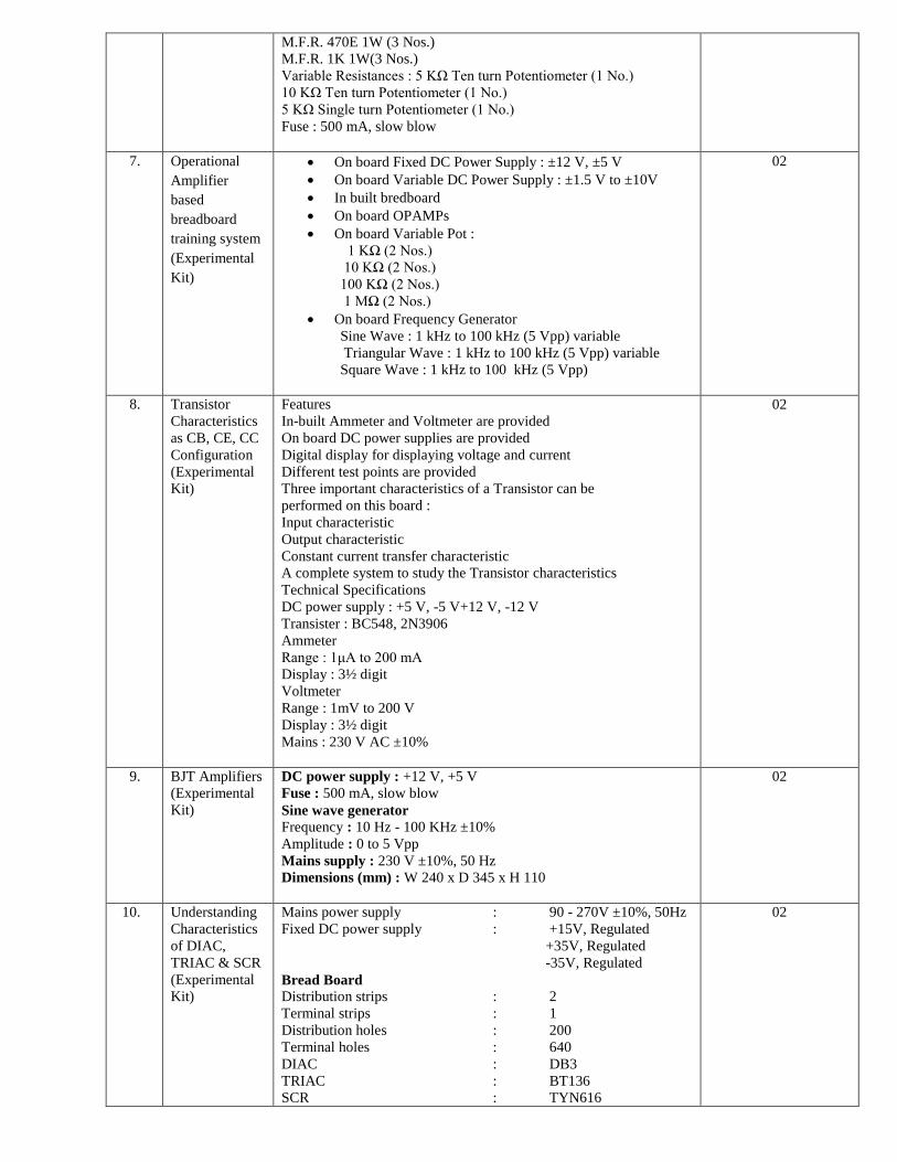
M.F.R. 470E 1W (3 Nos.)
M.F.R. 1K 1W(3 Nos.)
Variable Resistances : 5 KΩ Ten turn Potentiometer (1 No.)
10 KΩ Ten turn Potentiometer (1 No.)
5 KΩ Single turn Potentiometer (1 No.)
Fuse : 500 mA, slow blow
7. Operational
Amplifier
based
breadboard
training system
(Experimental
Kit)
On board Fixed DC Power Supply : ±12 V, ±5 V
On board Variable DC Power Supply : ±1.5 V to ±10V
In built bredboard
On board OPAMPs
On board Variable Pot :
1 KΩ (2 Nos.)
10 KΩ (2 Nos.)
100 KΩ (2 Nos.)
1 MΩ (2 Nos.)
On board Frequency Generator
Sine Wave : 1 kHz to 100 kHz (5 Vpp) variable
Triangular Wave : 1 kHz to 100 kHz (5 Vpp) variable
Square Wave : 1 kHz to 100 kHz (5 Vpp)
02
8. Transistor
Characteristics
as CB, CE, CC
Configuration
(Experimental
Kit)
Features
In-built Ammeter and Voltmeter are provided
On board DC power supplies are provided
Digital display for displaying voltage and current
Different test points are provided
Three important characteristics of a Transistor can be
performed on this board :
Input characteristic
Output characteristic
Constant current transfer characteristic
A complete system to study the Transistor characteristics
Technical Specifications
DC power supply : +5 V, -5 V+12 V, -12 V
Transister : BC548, 2N3906
Ammeter
Range : 1μA to 200 mA
Display : 3½ digit
Voltmeter
Range : 1mV to 200 V
Display : 3½ digit
Mains : 230 V AC ±10%
02
9. BJT Amplifiers
(Experimental
Kit)
DC power supply : +12 V, +5 V
Fuse : 500 mA, slow blow
Sine wave generator
Frequency : 10 Hz - 100 KHz ±10%
Amplitude : 0 to 5 Vpp
Mains supply : 230 V ±10%, 50 Hz
Dimensions (mm) : W 240 x D 345 x H 110
02
10. Understanding
Characteristics
of DIAC,
TRIAC & SCR
(Experimental
Kit)
Mains power supply : 90 - 270V ±10%, 50Hz
Fixed DC power supply : +15V, Regulated
+35V, Regulated
-35V, Regulated
Bread Board
Distribution strips : 2
Terminal strips : 1
Distribution holes : 200
Terminal holes : 640
DIAC : DB3
TRIAC : BT136
SCR : TYN616
02
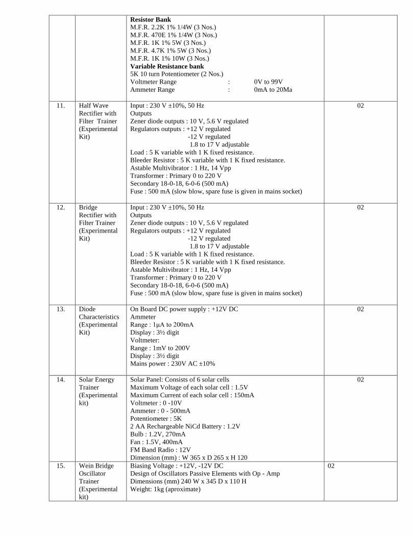
Resistor Bank
M.F.R. 2.2K 1% 1/4W (3 Nos.)
M.F.R. 470E 1% 1/4W (3 Nos.)
M.F.R. 1K 1% 5W (3 Nos.)
M.F.R. 4.7K 1% 5W (3 Nos.)
M.F.R. 1K 1% 10W (3 Nos.)
Variable Resistance bank
5K 10 turn Potentiometer (2 Nos.)
Voltmeter Range : 0V to 99V
Ammeter Range : 0mA to 20Ma
11. Half Wave
Rectifier with
Filter Trainer
(Experimental
Kit)
Input : 230 V ±10%, 50 Hz
Outputs
Zener diode outputs : 10 V, 5.6 V regulated
Regulators outputs : +12 V regulated
-12 V regulated
1.8 to 17 V adjustable
Load : 5 K variable with 1 K fixed resistance.
Bleeder Resistor : 5 K variable with 1 K fixed resistance.
Astable Multivibrator : 1 Hz, 14 Vpp
Transformer : Primary 0 to 220 V
Secondary 18-0-18, 6-0-6 (500 mA)
Fuse : 500 mA (slow blow, spare fuse is given in mains socket)
02
12. Bridge
Rectifier with
Filter Trainer
(Experimental
Kit)
Input : 230 V ±10%, 50 Hz
Outputs
Zener diode outputs : 10 V, 5.6 V regulated
Regulators outputs : +12 V regulated
-12 V regulated
1.8 to 17 V adjustable
Load : 5 K variable with 1 K fixed resistance.
Bleeder Resistor : 5 K variable with 1 K fixed resistance.
Astable Multivibrator : 1 Hz, 14 Vpp
Transformer : Primary 0 to 220 V
Secondary 18-0-18, 6-0-6 (500 mA)
Fuse : 500 mA (slow blow, spare fuse is given in mains socket)
02
13. Diode
Characteristics
(Experimental
Kit)
On Board DC power supply : +12V DC
Ammeter
Range : 1μA to 200mA
Display : 3½ digit
Voltmeter:
Range : 1mV to 200V
Display : 3½ digit
Mains power : 230V AC ±10%
02
14. Solar Energy
Trainer
(Experimental
kit)
Solar Panel: Consists of 6 solar cells
Maximum Voltage of each solar cell : 1.5V
Maximum Current of each solar cell : 150mA
Voltmeter : 0 -10V
Ammeter : 0 - 500mA
Potentiometer : 5K
2 AA Rechargeable NiCd Battery : 1.2V
Bulb : 1.2V, 270mA
Fan : 1.5V, 400mA
FM Band Radio : 12V
Dimension (mm) : W 365 x D 265 x H 120
02
15. Wein Bridge
Oscillator
Trainer
(Experimental
kit)
Biasing Voltage : +12V, -12V DC
Design of Oscillators Passive Elements with Op - Amp
Dimensions (mm) 240 W x 345 D x 110 H
Weight: 1kg (aproximate)
02
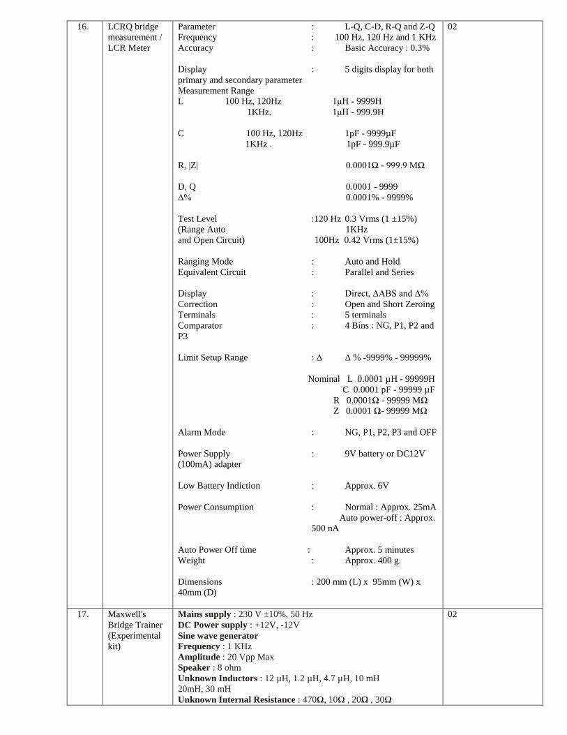
16. LCRQ bridge
measurement /
LCR Meter
Parameter : L-Q, C-D, R-Q and Z-Q
Frequency : 100 Hz, 120 Hz and 1 KHz
Accuracy : Basic Accuracy : 0.3%
Display : 5 digits display for both
primary and secondary parameter
Measurement Range
L 100 Hz, 120Hz 1μH - 9999H
1KHz. 1μH - 999.9H
C 100 Hz, 120Hz 1pF - 9999µF
1KHz . 1pF - 999.9µF
R, |Z| 0.0001Ω - 999.9 MΩ
D, Q 0.0001 - 9999
Δ% 0.0001% - 9999%
Test Level :120 Hz 0.3 Vrms (1 ±15%)
(Range Auto 1KHz
and Open Circuit) 100Hz 0.42 Vrms (1±15%)
Ranging Mode : Auto and Hold
Equivalent Circuit : Parallel and Series
Display : Direct, ΔABS and Δ%
Correction : Open and Short Zeroing
Terminals : 5 terminals
Comparator : 4 Bins : NG, P1, P2 and
P3
Limit Setup Range : Δ Δ % -9999% - 99999%
Nominal L 0.0001 µH - 99999H
C 0.0001 pF - 99999 µF
R 0.0001Ω - 99999 MΩ
Z 0.0001 Ω- 99999 MΩ
Alarm Mode : NG, P1, P2, P3 and OFF
Power Supply : 9V battery or DC12V
(100mA) adapter
Low Battery Indiction : Approx. 6V
Power Consumption : Normal : Approx. 25mA
Auto power-off : Approx.
500 nA
Auto Power Off time : Approx. 5 minutes
Weight : Approx. 400 g.
Dimensions : 200 mm (L) x 95mm (W) x
40mm (D)
02
17. Maxwell's
Bridge Trainer
(Experimental
kit)
Mains supply : 230 V ±10%, 50 Hz
DC Power supply : +12V, -12V
Sine wave generator
Frequency : 1 KHz
Amplitude : 20 Vpp Max
Speaker : 8 ohm
Unknown Inductors : 12 µH, 1.2 µH, 4.7 µH, 10 mH
20mH, 30 mH
Unknown Internal Resistance : 470Ω, 10Ω , 20Ω , 30Ω
02
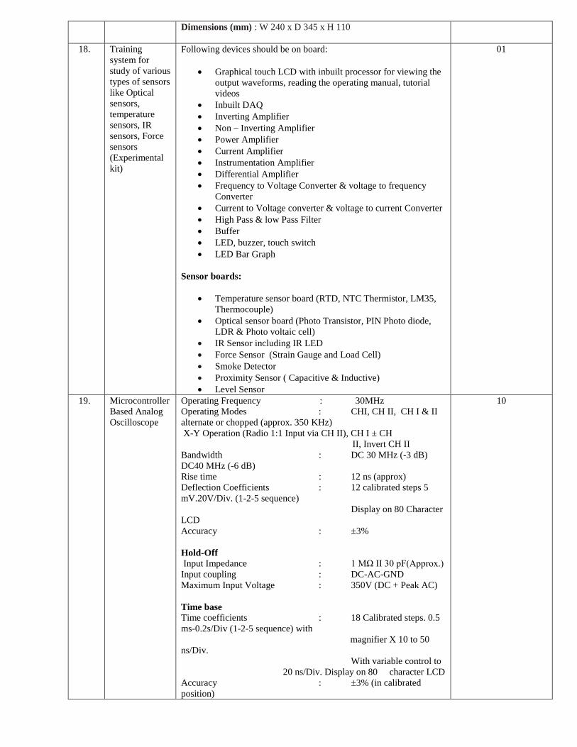
Dimensions (mm) : W 240 x D 345 x H 110
18. Training
system for
study of various
types of sensors
like Optical
sensors,
temperature
sensors, IR
sensors, Force
sensors
(Experimental
kit)
Following devices should be on board:
Graphical touch LCD with inbuilt processor for viewing the
output waveforms, reading the operating manual, tutorial
videos
Inbuilt DAQ
Inverting Amplifier
Non – Inverting Amplifier
Power Amplifier
Current Amplifier
Instrumentation Amplifier
Differential Amplifier
Frequency to Voltage Converter & voltage to frequency
Converter
Current to Voltage converter & voltage to current Converter
High Pass & low Pass Filter
Buffer
LED, buzzer, touch switch
LED Bar Graph
Sensor boards:
Temperature sensor board (RTD, NTC Thermistor, LM35,
Thermocouple)
Optical sensor board (Photo Transistor, PIN Photo diode,
LDR & Photo voltaic cell)
IR Sensor including IR LED
Force Sensor (Strain Gauge and Load Cell)
Smoke Detector
Proximity Sensor ( Capacitive & Inductive)
Level Sensor
01
19. Microcontroller
Based Analog
Oscilloscope
Operating Frequency : 30MHz
Operating Modes : CHI, CH II, CH I & II
alternate or chopped (approx. 350 KHz)
X-Y Operation (Radio 1:1 Input via CH II), CH I ± CH
II, Invert CH II
Bandwidth : DC 30 MHz (-3 dB)
DC40 MHz (-6 dB)
Rise time : 12 ns (approx)
Deflection Coefficients : 12 calibrated steps 5
mV.20V/Div. (1-2-5 sequence)
Display on 80 Character
LCD
Accuracy : ±3%
Hold-Off
Input Impedance : 1 MΩ II 30 pF(Approx.)
Input coupling : DC-AC-GND
Maximum Input Voltage : 350V (DC + Peak AC)
Time base
Time coefficients : 18 Calibrated steps. 0.5
ms-0.2s/Div (1-2-5 sequence) with
magnifier X 10 to 50
ns/Div.
With variable control to
20 ns/Div. Display on 80 character LCD
Accuracy : ±3% (in calibrated
position)
10
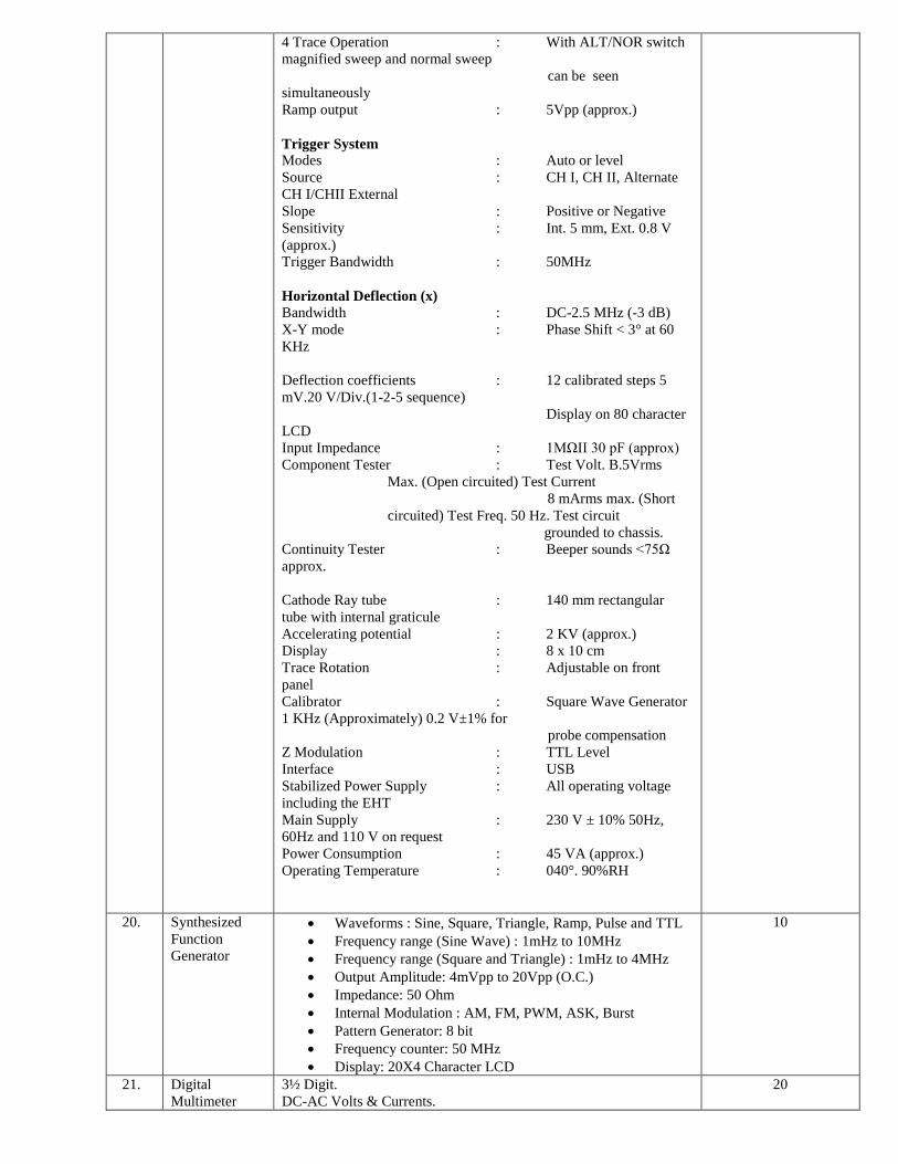
4 Trace Operation : With ALT/NOR switch
magnified sweep and normal sweep
can be seen
simultaneously
Ramp output : 5Vpp (approx.)
Trigger System
Modes : Auto or level
Source : CH I, CH II, Alternate
CH I/CHII External
Slope : Positive or Negative
Sensitivity : Int. 5 mm, Ext. 0.8 V
(approx.)
Trigger Bandwidth : 50MHz
Horizontal Deflection (x)
Bandwidth : DC-2.5 MHz (-3 dB)
X-Y mode : Phase Shift < 3° at 60
KHz
Deflection coefficients : 12 calibrated steps 5
mV.20 V/Div.(1-2-5 sequence)
Display on 80 character
LCD
Input Impedance : 1MΩII 30 pF (approx)
Component Tester : Test Volt. B.5Vrms
Max. (Open circuited) Test Current
8 mArms max. (Short
circuited) Test Freq. 50 Hz. Test circuit
grounded to chassis.
Continuity Tester : Beeper sounds <75Ω
approx.
Cathode Ray tube : 140 mm rectangular
tube with internal graticule
Accelerating potential : 2 KV (approx.)
Display : 8 x 10 cm
Trace Rotation : Adjustable on front
panel
Calibrator : Square Wave Generator
1 KHz (Approximately) 0.2 V±1% for
probe compensation
Z Modulation : TTL Level
Interface : USB
Stabilized Power Supply : All operating voltage
including the EHT
Main Supply : 230 V ± 10% 50Hz,
60Hz and 110 V on request
Power Consumption : 45 VA (approx.)
Operating Temperature : 040°. 90%RH
20. Synthesized
Function
Generator
Waveforms : Sine, Square, Triangle, Ramp, Pulse and TTL
Frequency range (Sine Wave) : 1mHz to 10MHz
Frequency range (Square and Triangle) : 1mHz to 4MHz
Output Amplitude: 4mVpp to 20Vpp (O.C.)
Impedance: 50 Ohm
Internal Modulation : AM, FM, PWM, ASK, Burst
Pattern Generator: 8 bit
Frequency counter: 50 MHz
Display: 20X4 Character LCD
10
21. Digital
Multimeter
3½ Digit.
DC-AC Volts & Currents.
20

Resistance / Diode / Continuity Testing.
Capacitance /frequency/ Measurement.
Transistor HFE Measurement.
10A Range Fuse Protected.
Palm size with built-in tilt stand.
Auto Polarity.
Over Range indication.
2.5 Measurement/Sec.
Palm size with built-in tilt stand.
Function
DC Voltage 200mv/2v/20v/200v/1000v 0.5% of rdg ±1D/±0.6% of
rdg ±2D , 1000 VDC or Peak AC
AC Voltage 200mv/2v/20v/200v/750v, 0.5% of rdg ±1D/±0.6% of
rdg ±2D , 750 V rms
DC Current 2-20-200mA ± 1.2% of rdg ± 1D , 0.5 A/250 V fuse
10A , 10A ± 2.0% of rdg ± 4D , 10A/250V Fuse
,10A / 60Sec. Max
AC Current 2-20-200mA, 10A , ±1.8% of rdg±, 3D , ± 3.0% of rdg,
± 4D , 0.5A/250V fuse
Resistance 200Ω/2-2000kΩ/20MΩ , 3V DC, 0.3V DCV
Diode Test Voltage 2V Test Current 10.6 mA
Capacitance 200pF/20-200nF/2-20μF , ±5% of rdg±1D , 400Hz-
50mV
Frequency (Auto Range) 2KHz-15MHz ± 5% of rdg ± 1D , Trig -
Lo - 1 Vrms , Trig-Hi - 2 Vrms
Continuity : 200Ω Beeper Sounds < 40Ω ±10 D
Resolution : For DC V & AC V : 10 V
For DC A& AC A : 1 A
Res : 0.1Ω
Frequency : 10 Hz
Large Size LCD Display : 3 Digit - 1999 counts
Auto zero/ Auto Polarity
Over Range indication
Power - 9 V Battery : Typical - 225 Hours
Low Battery Indication
Operating Condition : 0.50 C - 75% RH
22. True RMS
Digital Multi-
meter
4½ Digit,True RMS Digital Multimeter
Wide measurement capabilities : DCV / ACV, DCA / ACA,
Frequency, Resistance, diode, triode, continuity tester etc.
Auto Ranging selection
A Dual Liquid crystal, Display that allows two properties of
an input signal to be displayed at the same time.
True RMS AC Voltage and current measurements
Frequency measurement to greater than 300 KHz
10 µV sensitivity in volts DC
Decibels with variable reference impedence measurement
capability
A compare mode (COMP) to determine, if a measurement is
within, above or below a designated range.
Slow and fast selectable count resolution
Function modifier to perform REL, dBm, HOLD, MN MX
and COMP Function
02
23. Multi Output
Variable Power
Supply
DC Output :
A : 0-30 V, 2 A, continuously variable by means of Coarse and Fine controls B : 5 V, 2 A adjustable from 4V - 6V C : 0 - ±15 V, 1 A Dual Tracking adjustable
04

Current Limit : 100 mA - 2 A continuously adjustable for (0-
30 V & 5 V) 100 mA - 1 A continuously adjustable for (± 15
V)
Display: 3 digit for voltage & 3 digit for current LED
indication for voltage & current
Short circuit protected
24. Connecting
leads
(Stackable)
Length- 1½ Feet
2 mm
100
25. g) CRO probes
(BNC to BNC)
BNC to BNC 1 meter 10
26. h) CRO probes
(BNC to
CROCODILE
Clip cable)
BNC to CROCODILE Clip cable 1 meter 30
27. Logic Gates
Trainer
(Experimental
kit)
Input : +5V DC
Logic levels : +5V : HIGH ( Logic 1 )
0V : LOW ( Logic 0 )
Scope of Learning
Study of AND gate and to verify its truth table
Study of OR gate and to verify its truth table
Study of NOT gate and to verify its truth table
Study of NAND gate and to verify its truth table
Study of NOR gate and to verify its truth table
Study of XOR gate and to verify its truth table
Study of XNOR gate and to verify its truth table
02
28. Analog-Digital
Bread Board
Training
system
(Experimental
kit)
Technical Specifications
DC Power Supplies : + 5V; 1A (Fixed)
+ 15V; 1A (Fixed)
15V; 1A (Fixed)
+ 15V; 200mA (Variable)
15V; 200mA (Variable)
AC Supply : 5V- 0V- 5V, 10V- 0V- 10V can be used as 5V,
10V, 15V,20V & also as center tap.
Breadboard : 172.5mm x 128.5mm.
Test Points : 1685 nos (Gold plated)
Sine/Square/TTL Generator : Frequency range 10Hz to
1MHz in 4 steps and variable within the steps
Output : Sine wave : 15Vpp
Square Wave : 10Vpp
TTL : 5V
Fixed TTL (Clock) : 0.1Hz
Data Switches : 8 in Nos (Toggle switches for
High/Low TTL levels)
LED Display : 8 in Nos (for High/Low TTL levels
indication)
Logic Probe : Logic level indicator for TTL (7
Seg.)
Potentiometers : 6 in nos. (100 Ohm to 47KOhm)
Speaker : 8 ohms for audio use
Interactive Teaching Software with hardware lock:
It is Innovative Electronics Teaching software to provide
Theoretical & Practical training required for under-standing the
fundamental of Basic Electronics. It is unique software package to
deliver high quality Courseware to student and teachers both
05
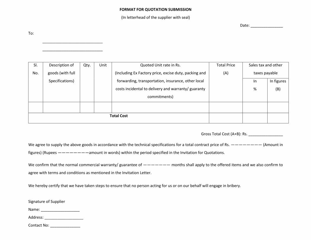
FORMAT FOR QUOTATION SUBMISSION
(In letterhead of the supplier with seal)
Date: _______________
To:
____________________________
____________________________
Sl.
No.
Description of
goods (with full
Specifications)
Qty. Unit Quoted Unit rate in Rs.
(Including Ex Factory price, excise duty, packing and
forwarding, transportation, insurance, other local
costs incidental to delivery and warranty/ guaranty
commitments)
Total Price
(A)
Sales tax and other
taxes payable
In
%
In figures
(B)
Total Cost
Gross Total Cost (A+B): Rs. ________________
We agree to supply the above goods in accordance with the technical specifications for a total contract price of Rs. ———————— (Amount in
figures) (Rupees ————————amount in words) within the period specified in the Invitation for Quotations.
We confirm that the normal commercial warranty/ guarantee of ——————— months shall apply to the offered items and we also confirm to
agree with terms and conditions as mentioned in the Invitation Letter.
We hereby certify that we have taken steps to ensure that no person acting for us or on our behalf will engage in bribery.
Signature of Supplier
Name: __________________
Address: __________________
Contact No: ______________