investigation report m/v finnclipper, grounding off ... · the investigation report should not be...
TRANSCRIPT

This investigation report was written to improve safety and prevent new accidents. The report does not addressthe possible responsibility or liability caused by the accident. The investigation report should not be used for pur-poses other than the improvement of safety.
Investigation reportB 1/2004 M
M/V FINNCLIPPER, grounding off Kapellskär 20.01.2004
Translation of the original Finnish report

B 1/2004 M
M/V FINNCLIPPER, grounding off Kapellskär 20.01.2004
I
SUMMARY
M/V FINNCLIPPER GROUNDING OFF KAPELLSKÄR 20.01.2004
Ro-Ro- / passenger vessel FINNCLIPPER left the Kapellskär harbors pier No.4 on 20.01.2004 at02.03 Finnish time towards Naantali. Master did take care of the departure arrangements by him-self. He estimated the northeast wind speed to be 12–17 m/s. North eastern wind presses thevessel against the pier from the port side. Master took first the bow out from the pier by bowthrusters while the stern was lying on the last fender towards shoreline. There after the stern waslet go by increasing the main engine power forward, the rudders being to the starboard.
The Chief officer entered the bridge at 02.06 when the ship was already moving. Chief officerinformed master that the stern was coming closer to the pier and master made correction align-ment to the right by the rudder. This is how it was continued until the stern had passed the piersedge. After this the master changed his steering position in the middle of the bridge, the rudderbeing in the middle, the main propellers output 23 % forward and he didn’t activate the bowthrusters in the middle cockpit steering position.
As per VDR recording the “Predictor” did point the vessel to drift towards the buoy north of theKapellskärs skäret. Neither the Master nor the Chief officer did monitor the “Predictor”s display.The passage was resumed with similar propeller blade-and rudder adjustments, bow thrustersbeing in zero position. About 02.09 Master turned the rudder about 20° to the left leaving theother means of steering as they were. The vessel was continuing the drift due to lack of steeringefforts towards to the before mentioned buoy. When the stern was coming closer to the buoy02.09.50 master increased the propellers output to 32 % and turned rudder 15° to the starboardin order to avoid the stern to collide on the buoy. The vessels sterns sb-side collision bar did col-lide on the buoy at 02.10.30 and there after the vessel run on the ground located on the northeastern side of the island. The vessel run over the ground and the vessels bottom was damagedin the entire length.
The vessel’s damages did neither cause any danger to sink nor stability problems. The vesselreturned to Kapellskär at 03.36 where the passengers and cargo was discharged.
The reasons which lead to the accident were inadequate familiarization to the ships handling andits equipment, lack of use of the steering- and navigational equipment and lack of bridge resourcemanagement.

B 1/2004 M
M/V FINNCLIPPER, grounding off Kapellskär 20.01.2004
II
USED ABBREVIATIONS
AIS Automatic Information System.
ARPA Automatic Radar Plotting Aid.
COG Course Over Ground.
DGPS Differential Global Positioning System.
DPA Designated person ashore
GPS Global Positioning System.
ECDIS Electronic Chart Display and Information System.
IEC International Electro technical Commission.
IMO International Maritime Organization.
IMDG International Maritime Dangerous Goods (Code).
ISM International Safety Management (Code).
MF/ HF Medium Frequency / High Frequency
OOW Officer on watch
SENC System Electronic Navigation Chart.
SOLAS Safety of Life at Sea.
VDR Voyage Data Recorder.
VDC Voyage Data Capsule.
VHF Very High Frequency
VTS Vessel Traffic Service.
UTC Universal Coordinated Time

B 1/2004 M
M/V FINNCLIPPER, grounding off Kapellskär 20.01.2004
III
CONTENTS
SUMMARY......................................................................................................................................... I
USED ABBREVIATIONS.................................................................................................................. II
FOREWORD.....................................................................................................................................V
1 EVENTS AND INVESTIGATIONS............................................................................................... 1
1.1 Ship ...................................................................................................................................... 1
1.1.1 General data............................................................................................................. 1
1.1.2 Manning.................................................................................................................... 2
1.1.3 Wheelhouse and the navigation equipments........................................................... 2
1.1.4 Other arrangements ................................................................................................. 6
1.1.5 Cargo...................................................................................................................... 11
1.2 Incident voyage.................................................................................................................. 12
1.2.1 Voyage and it’s planning ........................................................................................ 12
1.2.2 Scene ..................................................................................................................... 22
1.2.4 Weather conditions................................................................................................. 24
1.2.5 Ship’s damages...................................................................................................... 25
1.2.6 Predictor shown in the navigation equipments. ..................................................... 26
1.2.7 Action by VTS- system........................................................................................... 27
1.2.8 Actions after the accident....................................................................................... 27
1.3 Rescue operation............................................................................................................... 28
1.3.1 Alerting actions....................................................................................................... 28
1.3.2 Commencement of rescue operation..................................................................... 28
1.3.3 Actions by the crew ................................................................................................ 28
1.4 Relevant directions and rules guiding the operation. ........................................................ 28
1.4.1 Rules and guidelines issued by the authorities...................................................... 28
1.4.2 Some of the company procedures. ........................................................................ 29
1.4.3 Bridge Resource Management .............................................................................. 31
1.5 Special studies by the investigation commission .............................................................. 32
2 ANALYSIS.................................................................................................................................. 33
2.1 Bridge................................................................................................................................. 33
2.2 About the company procedures......................................................................................... 33
2.3 Alerting- and rescue operation........................................................................................... 35
2.4 Weather conditions influence on the movements of the ship............................................ 35
2.5 Route marking.................................................................................................................... 36
2.6 VDR.................................................................................................................................... 36

B 1/2004 M
M/V FINNCLIPPER, grounding off Kapellskär 20.01.2004
IV
3 CONCLUSIONS ........................................................................................................................ 39
3.1 Sequence chain ................................................................................................................. 39
3.2 Contributing factor ............................................................................................................. 39
3.3 Other safety observation.................................................................................................... 40
4 RECOMMENDATIONS ............................................................................................................. 41
REFERENCES

B 1/2004 M
M/V FINNCLIPPER, grounding off Kapellskär 20.01.2004
V
FOREWORD
The Accident Investigation Board got information about the grounding of FINNCLIPPER20.1.2004 at 0800 hours. Accident Investigation Board were in contact with the Swedishmaritime authorities and to the shipping company and received immediate informationabout the accident.
The Accident Investigation Board appointed on 27.1.2004 investigation commission toinvestigate the accident. Captain Juha Sjölund acted as chairman of the commissionand Captain Micael Vuorio as member of the commission.
Finnish investigation authorities acted in accordance to the IMO resolution A.849(20)concerning accident investigation as the leading party of the investigation. Captain Jör-gen Zachau from Swedish Maritime Authority investigation unit was called as an ob-server in the investigation.
VDR (Voyage Data Recorder) is fitted on board in accordance to SOLAS new V para-graph rule 20. The investigators visited the company to familiarize to the recordings bylead of company safety manager and received the recordings for investigation purposes.The Accident Investigation Board purchased the manufacturers data program dedicatedto the vessel by permission of the company. By this program the investigators were ableto investigate the recordings in the Accident Investigation Board premises. It is the firsttime when VDR was used in the investigation, therefore the subject is handled a littleextensively.
The investigators heard the master in the Accident Investigation Board premises on18.2.2004 about the events prior the accident. When the vessel had returned back totraffic, the chief officer was heard on board FINNCLIPPER on 23.3.2004 and the inves-tigators familiarized themselves to the vessel.
The investigators were present in Masters maritime declaration, which was held in Turkuon 24.2.2004. The sea court delivered later the minutes of the clearance with attach-ments to the Accident Investigation Board.
Captain Micael Vuorio prepared the Kapellskärs harbour outlines in the Sydväst Sjöfartsimulator and so the investigators had opportunity to get acquainted in different possi-bilities to handle vessels in the harbour. (Model of FINNCLIPPER was not available).Captain Kari Larjo was present in the simulator as an expert.
Statements concerning the investigation report. In accordance to the act (79/1996)24 § concerning accident investigation the final draft of the report was sent for statementto Finnlines Ltd and Swedish Maritime Administration. The statement from Sjöfarstverketand comments from the master and chief officer has been noticed in the text. Receivedstatements are attached.
B 1/2004 M
M/V FINNCLIPPER, grounding off Kapellskär 20.01.2004
1
1 EVENTS AND INVESTIGATIONS
1.1 Ship
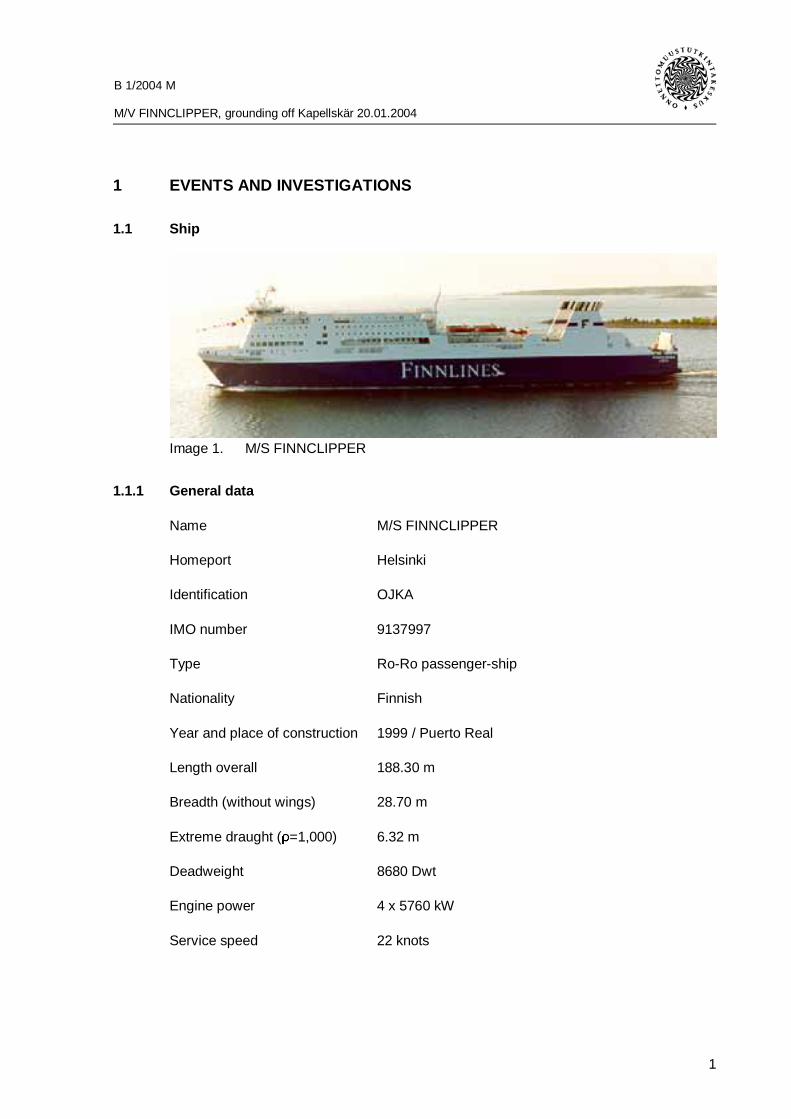
Image 1. M/S FINNCLIPPER
1.1.1 General data
Name M/S FINNCLIPPER
Homeport Helsinki
Identification OJKA
IMO number 9137997
Type Ro-Ro passenger-ship
Nationality Finnish
Year and place of construction 1999 / Puerto Real
Length overall 188.30 m
Breadth (without wings) 28.70 m
Extreme draught (ρ=1,000) 6.32 m
Deadweight 8680 Dwt
Engine power 4 x 5760 kW
Service speed 22 knots

B 1/2004 M
M/V FINNCLIPPER, grounding off Kapellskär 20.01.2004
2
1.1.2 Manning
Ships manning certificate dated on 19.11.2002 (valid until 01.01.2008) required 15 per-sons crew. There was on board 28 crewmembers+2 apprentices at the time of the acci-dent
Master had received captains license 1976. The present license is valid until20.03.2006. Swedish pilot certificate from sea via Tjärven–Kapellskär had been issuedon 10.04.2003 which covers ship FINNSAILOR and FINNCLIPPER. Line pilot certificatefor passenger ship for Naantali–Nyhamn have been issued on 24.06.2003 and concernsships FINNCLIPPER, FINNEAGLE and FINNSAILOR. The master had familiarized him-self to FINNCLIPPER during four days in December 2003. Pilot examination trials hehad executed on summer 2003 during four trips. These pilot examination trials did con-cern fairway parts in Finland and Sweden on FINNCLIPPER. Ships berthing and un-berthing were not included in these pilotage trials. Master embarked vessel 19.01.2004and had 13 hours time to be on board before the departure from Kapellskär.
Captains license was issued 1987 to the chief officer. The present license is valid until03.11.2005. He has sailed as a mate from year 1981 and from 1987 as chief officer / 1st
officer. From the year 2000 he has also acted as master deputy. He has Ro-Ro vesselexperience since year 1997.
1.1.3 Wheelhouse and the navigation equipments
1. Integrated navigation system Sperry Marine VMS-VT
2. Autopilot Sperry Marine ADG 3000 VT Steeringcontrol.
3. S-Band 10 cm Radar Sperry Marine VMS-VT
4. X-Band, 3 cm Radar Sperry Marine VMS-VT
5. DGPS position device Leica DGPS MK 10
6. DGPS position device Leica DGPS MX420 / AIS
7. Gyro Compass C.Plath Navigat 2100 Fiber-optic Gyrocompass
8. Gyro Compass Sperry Marine MK 37 VT Digital Gyro-compass
9. Magnetic Compass Magnetic Compass SR3 John Lillyand Gilly Ltd.
10. Speed log Sperry Marine Two Axis Doppler log
11. Electronic chart system Adveto Ecdis
12. Electronic chart material C-MAP
13. Echo sounder Sperry Marine ES 5000
14. AIS Leica & STN Atlas Marine electronicX531 UAIS

B 1/2004 M
M/V FINNCLIPPER, grounding off Kapellskär 20.01.2004
3
15. Anemometer Walker Thomas
16. Program for loading and damage sta-bility
Onboard-NAPA
17. MF/HF Radio Furuno AA-50
18. VHF Radio 3 x Furuno FM8500
19. GMDSS VHF Radio 3 x Navico Axis 250 GMDSS
20. Inmarsat C Furuno Felcom 11
Figure 2. Wheelhouse Arrangements
1. Radar2. Rudder
Override tillerKaMeWa joystickBow thrusters panelEngine order Telegraph
3. Conning DisplayAutopilot Display
4. ECDIS5. IACMS Ballast program6. Display for radar and ECDIS
RudderKaMeWa joystickBow thrusters panel
7. Chart table8. Safety Panel9. GMDSS panel
B 1/2004 M
M/V FINNCLIPPER, grounding off Kapellskär 20.01.2004
4
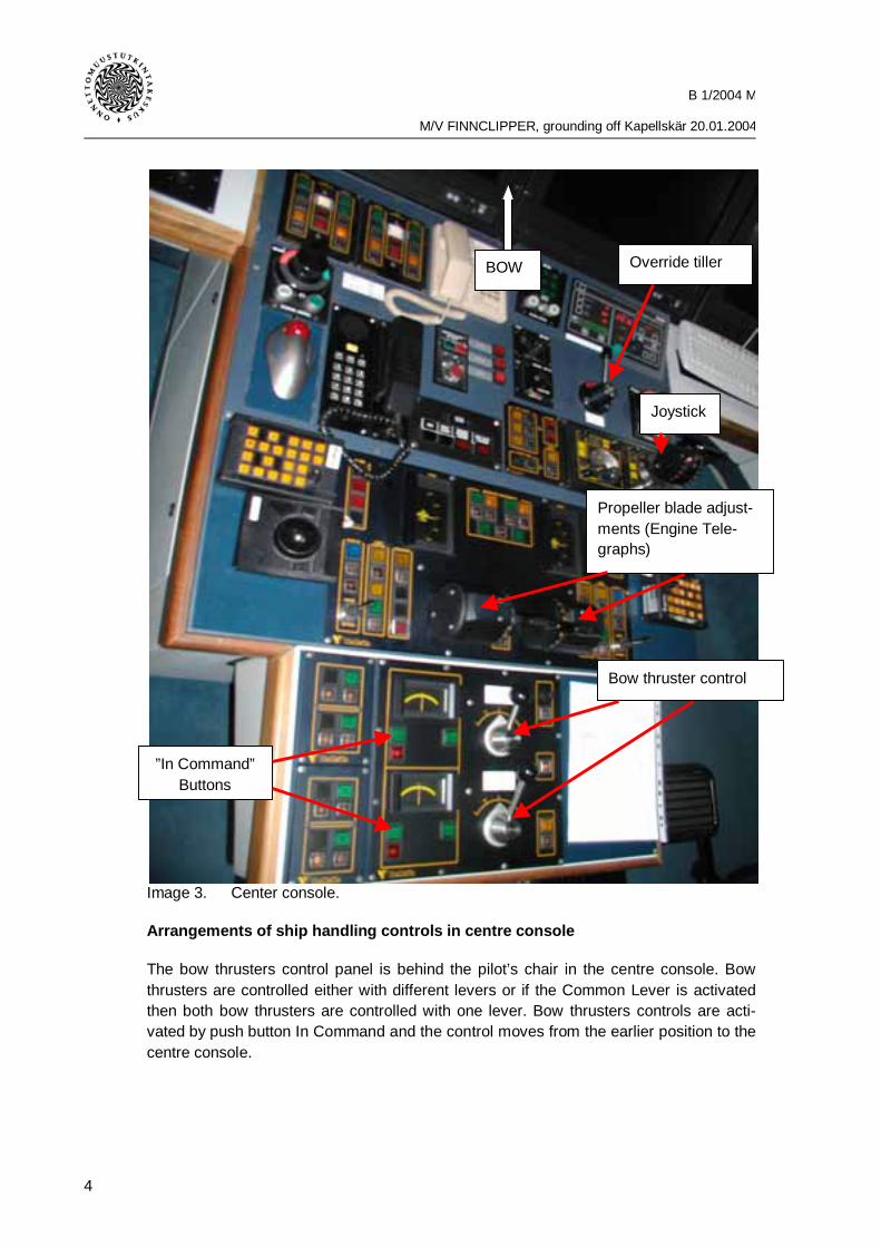
Image 3. Center console.
Arrangements of ship handling controls in centre console
The bow thrusters control panel is behind the pilot’s chair in the centre console. Bowthrusters are controlled either with different levers or if the Common Lever is activatedthen both bow thrusters are controlled with one lever. Bow thrusters controls are acti-vated by push button In Command and the control moves from the earlier position to thecentre console.
Bow thruster control
Propeller blade adjust-ments (Engine Tele-graphs)
Joystick
Override tillerBOW
”In Command”Buttons

B 1/2004 M
M/V FINNCLIPPER, grounding off Kapellskär 20.01.2004
5
Engine controls are in front of the bow thrusters control panel. There are two enginecontrols, one for each engine. Engine controls are activated by push button In Com-mand and the control moves from the earlier position to the next one.
There are two rudder controls in the centre console and they are situated on both sidesof the console beside the left and right control location. Rudder’s controls are activatedby pushing accept button beside the rudder control and the rudder control is shifted fromthe earlier position to the centre console. The two rudders cannot be separately handledfrom the centre console.
Override tiller is for the rudder, which is located beside the rudder control in the front ofcentre console. Turning the control handle activates override tiller and the rudder controlfrom other control places is shifted to the override tiller. There is also the KaMeWa-joystick, which is located between rudder and engine controls. KaMeWa-Joystick wasnot used.
Image 4. Control console on the sb-wing.
The respective controls, which are in the centre console, are also on the bridge wingconsoles. The only difference is that the rudder can be separately moved with the con-trols on the bridge wing. There are two methods in the rudder control panel, which canbe chosen either separate or syncron. Rudder and propellers independent use is built togive more transversal power to the stern when used in certain ways. Without increasingor decreasing the ahead/aster speed.

B 1/2004 M
M/V FINNCLIPPER, grounding off Kapellskär 20.01.2004
6
1.1.4 Other arrangements
VDR (Voyage Data Recorder)
There is a VDR installed on M/V FINNCLIPPER, that records information about the shipand its navigation equipments as in airplanes. The requirements about installation andschedule for VDR are stated in SOLAS, working description is stated in IMO resolutionA.861(20) and technical description is stated in IEC 61996 Standard.
REVISED SOLAS CHAPTER V
The International Maritime Organization (IMO) adopted a revised chapter V to theSOLAS Convention in December 2000 (Resolution MSC.99(73)). The revised chapter Ventered into force internationally on 1 July 2002. In Finland it was implemented on 1February 2003 by Act 1358/2002 and Presidential Decree 46/2003. The revised chapterV applies to all ships on all Voyages unless specifically otherwise provided in the Con-vention. Regulation 19 of the revised chapter V sets out requirements for ship bornenavigational systems and equipment. The regulation applies fully to new ships engagedon international voyages. Requirements for existing ships engaged on international voy-ages are contained in regulation 12 of the existing chapter V, and in regulations 19.2.1.6and 19.2.4.2 and regulation 20 of the revised chapter V.The revised chapter V has been set out in Act 1358/2002. The Finnish Maritime Admini-stration issued more detailed provisions on the carriage requirements for these ships.
Under regulation 20 of the revised SOLAS chapter V, ships engaged on internationalvoyages shall be fitted with a voyage data recorder (VDR), as follows:
1. New passenger ships before they are put into service.
2. Existing Ro-Ro passenger ships not later than the first survey for safety equip-ment on or after 1 July 2002.
3. Existing passenger ships other than Ro-Ro passenger ships not later than 1January 2004.
4. Cargo ships of 3,000 gross tonnage and upwards constructed on or after 1 July2002, before they are put into service.
The purpose of a voyage data recorder (VDR) is to maintain a store, in a secure and re-trievable form, of information concerning the position, movement, physical status, com-mand and control of a vessel over the period leading up to and following an incidenthaving an impact thereon. Information contained in a VDR should be made available toboth the Administration and the ship owner. This information is for use during any sub-sequent investigation to identify the cause(s) of the incident.
To ensure that the VDR continues to record events during an incident, it should be ca-pable to of operating from the ship’s emergency source of electrical power. If the Ship’semergency source of electrical power fails, the VDR should continue to record Bridge

B 1/2004 M
M/V FINNCLIPPER, grounding off Kapellskär 20.01.2004
7
audio from a dedicated reserve source of power for a period of 2 h. At the end of this 2 hperiod all recording should cease automatically.
The time for which all stored data items are retained should be at last 12 h. Data itemsthat are older than this may be overwritten with new data.
Data items to be recorded:
Date and time
Date and time, referenced to UTC, should be obtained from a source external to the shipor from an internal clock. The recording should indicate which source is in use.
Ships position
Latitude and longitude, and the datum used, should be derived from an electronic posi-tion -fixing system. The recording should ensure that the identity and status of the posi-tion -fixing system could always be determined on playback.
Speed
Speed through the water or speed over ground, including an indication of which it is. De-rived from the ship’s speed and distance-measuring equipment.
Heading
As indicated by the ship’s compass.
Bridge audio
One or more microphones positioned on the bridge, should be placed so that conversa-tions at or near the conning stations, radar displays, chart tables, etc., are adequatelyrecorded. As far as practicable, the positioning of microphones should also capture in-tercom, public address systems and audible alarms on the bridge.
Communication audio
VHF communications relating to ships operations should be recorded.

B 1/2004 M
M/V FINNCLIPPER, grounding off Kapellskär 20.01.2004
8
Radar data
This should include electronic signal information from within one of the ship’s radar in-stallations that records all the information that was actually being presented on themaster display of that radar at the time of recording. This should include range rings ormarkers, bearing markers, electronic plotting symbols, radar maps, whatever parts ofthe SENC or other electronic chart or map that were selected, The voyage plan, naviga-tional data, navigational alarms and the radar status data that were visible on the dis-play. The recording method should be such that, on playback, it is possible to present afaithful replica of the entire radar display.
Echo sounder
This should include the depth under keel, the depth scale currently being displayed andother status information where available.
Main alarms
This should include the status of all mandatory alarms on the bridge.
Rudder, order and response
This should include the status and setting of autopilot fitted.
Engine order and response
This should include the position of any engine telegraphs or direct engine/propeller con-trols and feedback indications, if fitted, including ahead/astern indicators. This shouldalso include of bow thrusters if fitted.
Hull openings status (Bow door, stern ramp and pilot doors)
This should include all mandatory status information required to be displayed on thebridge.
Watertight and fire door status
This should include all mandatory status information required to be displayed on thebridge.
Accelerations and hull stresses
Where a ship is fitted with hull stress and response monitoring equipment, all data itemsthat have been pre- selected within that equipment should be recorded.

B 1/2004 M
M/V FINNCLIPPER, grounding off Kapellskär 20.01.2004
9
Wind speed and direction
This should be applicable where ship is fitted with suitable sensor. Either relative or truewind speed and direction may be recorded, but an indication of which it is should be re-corded.
Protected storage unit, Voyage Data Capsule
The final recording medium should be installed in a protective capsule, which shouldmeet all of the following requirements:
- Be capable of being accessed following an incident but secure against tampering.
- Maximize the probability of survival and recovery of the final recorded data after anyincident
- Be of highly visible colour and marked with retro-reflective materials
- Be fitted with an appropriate device to aid location.
The design and construction of the Voyage Data Capsule is strict regulated what comesto penetration, fire protection, impact and immersion.
VDR Player
VDR player is the device to investigate the data restored in the VDR. VDR player is notincluded in the IMO resolution A.861(20).
VDR on M/V FINNCLIPPER
VDR of brand Consilium Navigation AB VDR-M2 was installed on M/V FINNCLIPPERduring construction. VDR-M2 system consists of a main unit and a capsule called Voy-age Data Capsule (VDC). The recording period in M/V FINNCLIPPER’s main unit is 24hrs. VDR-M2 records data according to IMO Resolution A.861(20), but also Speed overground and Course over ground from the GPS. Date and time is also recorded from theGPS. VDR-M2 has its own UPS as reserve source of power to ensure the VDR to rec-ord data for 2 hrs if the Ship’s emergency source of electrical power fails. The recordingperiod for the voyage data capsule is 12 hrs and the VDC is compliant to IEC 61996standard.

B 1/2004 M
M/V FINNCLIPPER, grounding off Kapellskär 20.01.2004
10
Image 5. VDR Capsule
VDR installation on M/V FINNCLIPPER
There is 7 microphones connected to the VDR on M/V FINNCLIPPER and they are situ-ated in the wheelhouse as following:
1 pc port bridge wing ceiling
1 pc starboard bridge wing ceiling
1 pc port cockpit ceiling
1 pc starboard cockpit ceiling
1 pc chart table ceiling
2 pc Safety console ceiling
B 1/2004 M
M/V FINNCLIPPER, grounding off Kapellskär 20.01.2004
11
DGPS position device Leica DGPS MK 10
DGPS position device Leica DGPS MX420 / AIS
Gyro Compass Sperry Marine MK 37 VT Digital Gyrocompass
Speed log Sperry Marine Two Axis Doppler Log
Echo sounder Sperry Marine ES 500
Anemometer Walker Thomas
Autopilot control Sperry Marine ADG 3000 VT Steering
S-Band 10 cm Radar Sperry Marine VMS-VT
X-Band 3 cm Radar Sperry Marine VMS-VT
Conning Display Sperry Marine VMS-VT
KaMeWa master control
Watertight doors Mimic panel
SEMCO Door status
Valmarine IACMS
Shaft RPM, Order / Response
Propellers pitch
Thrusters, Order / Response
Rudders, Order / Response
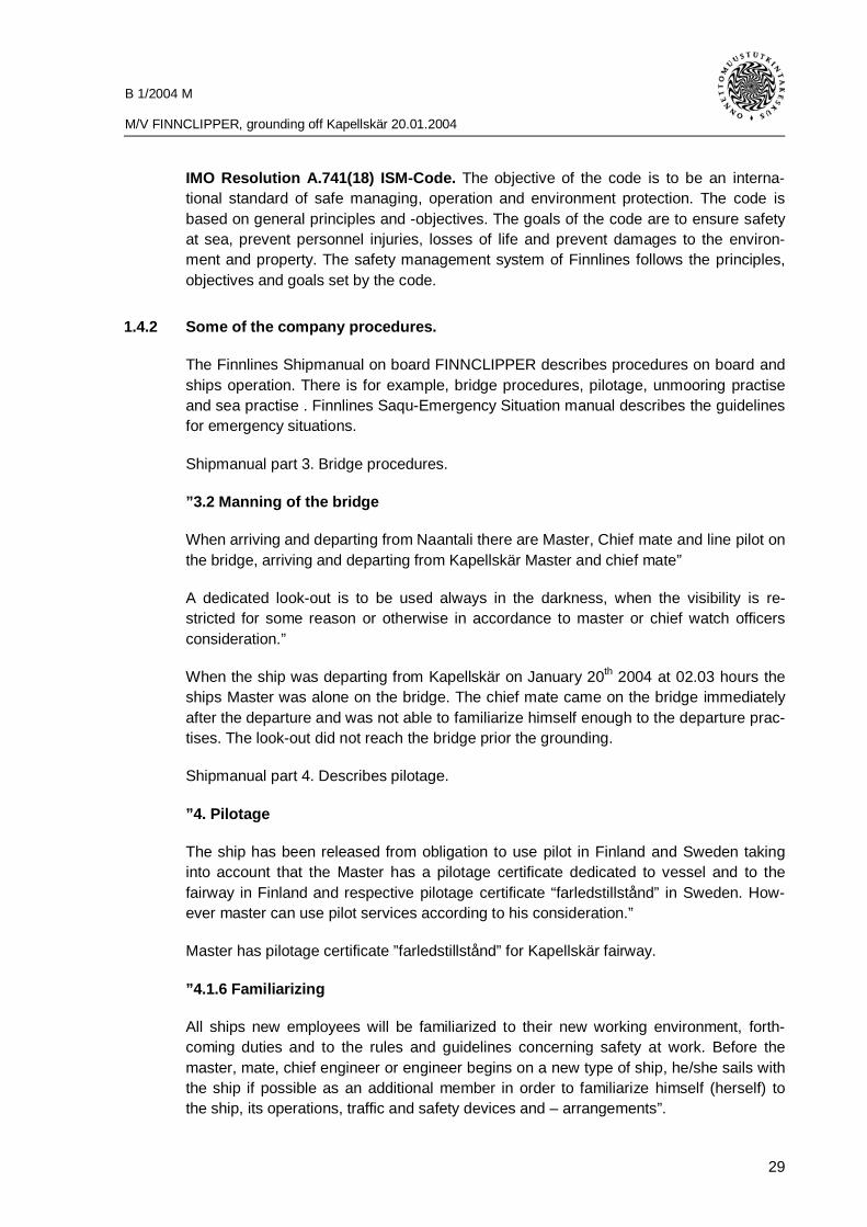
1.1.5 Cargo
The vessel had as cargo 51 lorries, 5 trailers and 2 cars on decks 3 and 5. For loading itwas used 1200 lane meters of the ship’s total lane meters 2459. The total weight of thecargo was 2377 tons of which 60,9 tons IMDG classified cargo.
Heavy and light fuel was totally 464 tons on board.

B 1/2004 M
M/V FINNCLIPPER, grounding off Kapellskär 20.01.2004
12
1.2 Incident voyage
1.2.1 Voyage and it’s planning
The Master boarded the vessel in Naantali 19.1.2004 and he was onboard for 13 hoursbefore the departure in Kapellskär. All this time he was awake and made him familiarwith the ship and her documents. According to the Master he did not feel tired. He madethe departure checklist before the departure and he was alone on the bridge. The chiefofficer arrived on the bridge after the departure. The Master was on the starboard bridgewing where he had following devices to assist him to manoeuvre: two main engines, twobow thrusters and two rudders, also Adveto Aecdis and Sperry’s electronic charts.
Chief officer heard on the walkie-talkie the Master’s order to let go when he was besidethe purser’s office on his way up from the car deck to the bridge. He rushed because theMaster was new on the ship. When he arrived on the bridge he undressed his jacket andwent to the starboard bridge wing. The first reaction for him was that the stern wascoming close the pier and he warned the Master about it. The Master did not notice thatthe stern was coming close to the pier but he trusted in the chief officer’s experience andput the rudders to starboard and it stopped getting closer. There was no communicationto the poop deck, the officer and two able bodied seamen that were on the poop deckduring departure had probably left after the Master notified about well head and stern.
When the stern was cleared from the pier the Master shifted to the centre console andthe chief officer was also moving over there but he noticed that the bow was comingclose to the buoy. The chief officer went back to the bridge wing and reported to theMaster about the buoy that was closing up. He did also mention that the ship is heavilydrifting to the right. The chief officer reported distances to the buoy and requested him totake to starboard because he knew that inside the buoy there is only one ship’s breadthof clear water. The Master turned the rudder to starboard in order to lift the stern to theleft.
Following times are from the VDR player audio and data files.
02:02:42 Engine controls up to the Bridge
02:03:00 Order to single up moorings.
02:04:15 Stern ramp is closing and the Brest line is singled up.
02:04:40 Let go head and stern
02:05:00 Bow thrusters 50% to port
02:05:24 Rudders 33° to starboard
02:05:33 Engine controls to level 3 ahead
02:05:49 Rudders 21° to starboard °
02:06:00 Headlines cleared
02:06:10 Rudders amidships

B 1/2004 M
M/V FINNCLIPPER, grounding off Kapellskär 20.01.2004
13
02:06:18 Rudders 14° to port
02:06:25 Well head and stern.
02:06:34 Rudders amidships
02:06:42 Bow thrusters to neutral
02:06:45 Chief officer arrives on the bridge
02:06:51 Chief officers warning for the closing of the stern to the pier
02:06:53 Rudders 30° to starboard
02:07:06 Rudders amidships
02:07:10 Rudders 24° to port
02:07:29 Rudders amidships
02:08:00 Rudders 10° to port
02:08:27 Rudders amidships
02:08:52 Master moving to the centre console, No communication on the bridge.
02:08:55 Rudders 21° to port. Manoeuvring from the centre console.
02:09:03 Engine controls received from starboard bridge wing to the centre console.
02:09:16 Rudders amidships
02:09:19 Rudders 24° to starboard °
02:09:22 Rudders eased to starboard 19° and engine order 4 forward
02:09:27 Rudders eased to starboard 6°
02:09:27Chief officer warning about the drift towards the buoy and tells the Masterto take up the stern in wind
02:09:30 Rudders 26° harder to starboard
02:09:35 Rudders eased to starboard 18°
02:09:45 Rudders amidships
02:09:50 Chief officer informs ‘’ coming ok like this ‘’
02:09:51 Rudders 19° to port
02:10:02 Rudders 34° to starboard
02:10:02 Chief officer informs ’’ don’t let the stern drift anymore”
02:10:04 Rudders 39° harder to starboard
02:10:05 Rudders 42° harder to starboard
02:10:06 Rudders 51° harder to starboard
02:10:06 Chief officer order the Master to take starboard rudder
02:10:07 Rudders 57° harder to starboard
02:10:08 Rudders 62° harder to starboard
02:10:15 Rudders eased to starboard 55°

B 1/2004 M
M/V FINNCLIPPER, grounding off Kapellskär 20.01.2004
14
02:10:15 Master notifies the ship drifting to starboard and the chief officer agrees
02:10:16 Rudders eased to starboard 48°
02:10:17 Rudders eased to starboard 37°
02:10:18 Rudders eased to starboard 33°
02:10:24 Rudders 49° harder to starboard
02:10:25 Rudders 62° harder to starboard
02:10:26 Rudders 67° harder to starboard
02:10:26 Chief officer informs that the buoy is alongside the ship
02:10:36 Chief officer informs that the buoy went astern
02:10:36 Rudders eased to starboard 58°
02:10:37 Rudders eased to starboard 52°
02:10:38Grounding, Echo sounder shows the lowest reading and vibrations fromthe ship can be heard in the VDR
02:10:39 Rudders eased to starboard 25°
02:10:40 Rudders amidships
02:10:45 Rudders 22° to port °
02:10:51 Engine controls to level 5 ahead
02:10:56Rudders amidships. According to the Masters emotional reaction we canassume that the ship run aground
02:11:04 Engine controls to level 3 ahead
02:11:07 Engine controls to level 2 ahead
02:11:10 Engine controls to level 1 ahead
02:11:15According to the conversation between the Master and the chief officer thesecond ground on the northwest side of Kapellskärs grund came as a sur-prise for them.
02:11:19 Engine controls to neutral
02:11:28 Master informs M/V Silja Europa about the grounding.
02:11:39 Port engine control to level 3 ahead
02:11:48 Engine controls to neutral
02:12:26 Starboard engine control to level 4 astern
02:12:38 Port engine control to level 2 ahead
02:12:44 Starboard engine control to level 2 astern
02:12:47 Rudders 39° to starboard
02:12:53 Starboard engine control to level 3 astern
02:12:55 Port engine control to level 3 ahead
02:13:04 Rudders eased to starboard 18°

B 1/2004 M
M/V FINNCLIPPER, grounding off Kapellskär 20.01.2004
15
02:13:08 Rudders amidships
02:13:15 Starboard engine control to level 4 astern
02:13:26 Port engine control to neutral
02:13:53 Port engine control to level 3 ahead
02:13:59 Bow thrusters activate in the centre console and 45% to starboard
02:14:15Verified that the propellers and rudders are working normally, Chief officersuggest to take the ship to shallower waters.
02:15:35Chief officer asks the Master if they should inform the VTS about thegrounding and he also warned the Master about a other ground moresouth, towards which the ship is drifting.
VDR displays propellers and bow thruster’s output as percentage from zero tohundred. On the screen units are erroneously shown as degrees although unitsshould be as percentage.

B 1/2004 M
M/V FINNCLIPPER, grounding off Kapellskär 20.01.2004
16
VDR Images from the accident voyage
VDR Image 1. Time 02:03:30 before the departure manoeuvring is on the starboardbridge wing. Wind information is shown in the left upper corner as truewind and speed. 30 degrees and 12.9 m/s (25 knots).
VDR Image 2. Time 02:04:50 bow thrusters output 50 % to port at the departure. Allthe other manoeuvring controls are neutral.

B 1/2004 M
M/V FINNCLIPPER, grounding off Kapellskär 20.01.2004
17
VDR Image 3. Time 02:05:35 head and stern lines are released. Rudders are 21° tostarboard and the propeller output is 12 % ahead.
VDR Image 4. Time 02:06:05 rudders are 14° to port and the bow thrusters output50 % to port. Ships stern is coming closer to the pier.

B 1/2004 M
M/V FINNCLIPPER, grounding off Kapellskär 20.01.2004
18
VDR Image 5. Time 02:06:35 rudders are 30° to starboard and the bow thrustersoutput is neutral. Ships speed over ground is 2.1 knots.
VDR Image 6. Time 02:08:20 rudders are 10° to port and the propeller output is23 % ahead. Ships speed over ground is 4.6 knots.

B 1/2004 M
M/V FINNCLIPPER, grounding off Kapellskär 20.01.2004
19
VDR Image 7. Time 02:08:50 rudders are 21° to port. The manoeuvring is done fromthe centre console. But the bow thrusters control is still activated onstarboard bridge wing. Predictor on the ECDIS display shows that thevessel is running aground.
VDR Image 8. Time 02:09:20 rudders are 6° to starboard and the propeller output is32 % ahead. Ships speed over ground is 5.6 knots. Heading line andthe predictor shows for a while that the ship is clear from the ground.

B 1/2004 M
M/V FINNCLIPPER, grounding off Kapellskär 20.01.2004
20
VDR Image 9. Time 02:10:20 rudders are 62° to starboard and the propellers outputis 32 % ahead. Ships speed over ground is 7.1 knots.
VDR Image 10. Time 02:10:42 grounding. Echo sounder without reading.

B 1/2004 M
M/V FINNCLIPPER, grounding off Kapellskär 20.01.2004
21
VDR Image 11. Time 02:11:00 echo sounder reading is 15.5 meter. Head of the shipis over the ground.
VDR Image 12. Time 02:11:23 all manoeuvring devices are neutral.

B 1/2004 M
M/V FINNCLIPPER, grounding off Kapellskär 20.01.2004
22
VDR Image 13. Time 02:14:06 bow thrusters control is activated in the centre console
1.2.2 Scene
Figure 6. Extract from Kapellskär special seachart 1:15000 (© Sjöfartsverket)
Grounding position

B 1/2004 M
M/V FINNCLIPPER, grounding off Kapellskär 20.01.2004
23
Kapellskär’s Ro-Ro harbour is located outside Stockholm in position 59° 43,4 N 019° 04E. The harbour is busy and it is used by both passenger- and Ro-Ro vessels. Berths 3and 4 of the piers are most often used by FINNCLIPPER. When leaving to the accidentvoyage the vessel was in berth 4. The pier is in direction about 296°–116°. The fairwayin which the vessel approaches and departs is in direction 269,5–089,5 degrees. Thefairways northern edge is indicated by Svedjelandet line marks and the southern edgeby Örarna line marks. Both line marks are in line 269,5–089,5 degrees. The breadth ofwater area indicated by these line marks is 300 meters wide. If ship’s handling in theharbour so requires can master, who is familiar to the area, get advantage also from thesouthern water area over the southern edge of the fairway just after the pier (see chart).The centre line of fairway is neither marked on the chart and nor in the nature. Thenorthern reef of the Kapellskärs skäret is marked with buoy which is 20 meters southfrom the line of Örarna. The 4.1 meters reef which is located northeast from Kapellskärsskäret is not marked with navigational safety device.
Image 7. Kapellskär harbour piers berth 3 and 4 on the right
Place of departure.

B 1/2004 M
M/V FINNCLIPPER, grounding off Kapellskär 20.01.2004
24
1.2.4 Weather conditions
In the following are described the weather circumstances before the grounding accord-ing to the weather information and weather forecasts received from the SMHI (Sverigesmeteorologiska och hydrologiska institute).
A deep low pressure moving from South Baltic over Poland affected the weather on Seaof Åland on January 20th 2004 and at the same time there was a high pressure reachingover North Scandinavia.
January 19th at 21.50 Rundradion program 1 weather forecast for the Kapellskär area:
Gale warning for the following areas: The Skaggerack, The Kattegatt, Lake Vänern,South and Southwest, Mid and Northern Baltic. Sea of Åland, Sea of archipelago, thesouthern part of the Gulf of Botnia.
Other Warnings: Risk for icing on ships in following areas: Gulf of Botnia, Sea of Åland,and Sea of archipelago And Northern Baltic.
Forecast until Tuesday night 20th of January
Northern Baltic, Sea of Åland and Sea of archipelago: Easterly Wind 14–18 m/s. Frommorning the wind is turning slowly to north. Snowfalls in some areas which will affect tothe visibility.
Wind registrations on Lighthouse Söderarm.
19th January at 21.00 the meteorological station on Lighthouse Söderarm registered awind of E 18 m/s. At 22.00 the wind was E 17m/s. 20th January at 01.00 the wind wasENE 15 m/s and 04.00 NE 13 m/s. Wind registrations are an average of readings from a10 minutes period. Lighthouse Söderarm is located at the fairway to Kapellskär at theborder between Archipelago of Stockholm and Sea of Åland 10 miles from Kapellskär.
Captain made a note in the departure checklist that the wind was 12 m/s from a directionof 020 degrees. There was no wind registration made in the ships log for the time of ac-cident.
Image 8 displays wind velocity in knots recorded by VDR.

B 1/2004 M
M/V FINNCLIPPER, grounding off Kapellskär 20.01.2004
25
Figure 8. Graphically shown wind registration in knots from the VDR
1.2.5 Ship’s damages
In the area between frames 10–60 in the stern was 1,2 m wide and 4–10 cm deep dent.In the ballast tank 20, lubrication waste oil tank 41, diesel oil drain tank 40 and heavyfuel oil drain tank 40 were leaks.
Between frames 59–170 in the mid ship was 3–5 m wide and 0–40 cm deep dent. In theheavy fuel oil overflow tank 60D, bilge tank 60SB, heavy fuel oil tank 60C, 70C, dieseloil 80C, heavy fuel oil tanks 90 and 100 C there were leaks.
In the ballast tanks BW 60SB, BW 80SB and BW 90B there were leaks.
Void spaces 4–10 were filled by water and got dirty by heavy fuel oil and diesel oil dueto broken jumper frames and pipe tunnel inner frames. Ballast pipes and connections tothe tanks were broken off. The remote sounding systems in the tanks were in electricshort cut and the sensors were filled by water. Engine alarm- and remote sounding sys-tem was broken. All electric cables were totally damaged in the void spaces which werefilled by water. The remote controlled valve control devices of the ballast- and fuel oilpipes were damaged by water. The guide rails of the forward sb-elevator were bent. Allthe piping insulations were totally damaged in the spaces which were filled by water.Part of the fuel oil and air pipes were damaged.

B 1/2004 M
M/V FINNCLIPPER, grounding off Kapellskär 20.01.2004
26
About 137 tons of steel were used to repairs and repairing expenses were about 2,5 M€. In addition the vessel was out of traffic 6 weeks.
Figure 9. A rough description of ship’s damages.
1.2.6 Predictor shown in the navigation equipments.
Predictor is a tool to estimate the ship future positions and behaviour of the vessel. Pre-dictor is shown on the electronic chart display and on the radar screen. The time fromcurrent position to the last predicted position is user selectable between 30 and 180second. The shape of predictor depends on the manufacturer. Predictor in M/SFINNCLIPPER ECDIS consists of 5 ships symbols connected to a vector that turns ac-cording to ships movements (see departure images 6–13). Predictor in M/SFINNCLIPPER ECDIS consists of a turning vector with dashed line. Predictor is usingthe transversal head speed, transversal stern speed, ships rate of turn and the longitu-dinal speed for the estimation of future positions and behaviour. The calculation as-sumes that the data is stabile.

B 1/2004 M
M/V FINNCLIPPER, grounding off Kapellskär 20.01.2004
27
1.2.7 Action by VTS- system
The VTS receives AIS information but they do not have radar surveillance in the area.
Image 10. Extract from ADVETO-chartdevice, which describes the vessels track fromberth to berth.
1.2.8 Actions after the accident
After the grounding the chief officer noticed that the bow thrusters were not activated inthe centre console. According to the masters Maritime Declaration the stern was turnedtowards the wind in west side of the fairway leading to Stockholm. The vessel was re-versed back to Kapellskär fairway after the Silja Europa had passed the vessel. Therewas no danger of collision in any time. Passengers and crew were provisionally in-formed about the accident. According to the containment team and engine room infor-mation the stability of the vessel was not endangered calculated by using worst-casescenario in the damage stability computer.

B 1/2004 M
M/V FINNCLIPPER, grounding off Kapellskär 20.01.2004
28
1.3 Rescue operation
1.3.1 Alerting actions
VTS-Stockholm got announcement about the grounding at 02.30 and Swedish Rescueat 02.36. After conversation between master and company safety manager (DPA) it wasdecided to return to Kapellskär at 02.50. The situation was explained also to the pas-sengers and crew and it was announced to them that the cargo will be discharged uponarrival to the berth.
1.3.2 Commencement of rescue operation
There were no observed leaks above the double bottom. Possible oil pollution was triedto observe by the searchlight. According to the master there was not immediate oil pol-lution danger because the tanks were filling and the oil was on top of the water. Whenthe draft and situation were stable the ship returned to Kapellskär berth no.4 at 03.36.According to company instructions the alcohol content of the blood was tested from thepersons who were on the bridge. The test result was 0 ‰ for all tested. The alcoholcontent of the blood was tested also from the master by the Swedish police and the re-sult was also 0 ‰.
The representatives of rescue organisation, Coast guard and Maritime Administrationdiscovered that obviously no oil pollution would occur due to cold water. At 05.00 all thecargo was discharged and all the passengers had disembarked the vessel. There afterthe crew resumed sounding the tanks and clear up the situation according to the in-structions received from the authorities and ship owner.
1.3.3 Actions by the crew
With the assistance of the technical sounding and stability calculation the crew couldquickly detect places of the ships leaks and stability. There was no immediate danger ofsinking or capsizing in any stage. There was no need to evacuate the passengers at seatherefore vessel returned to Kapellskär at 03.36 where both the passengers and cargowere discharged.
1.4 Relevant directions and rules guiding the operation.
1.4.1 Rules and guidelines issued by the authorities.
Finnish act concerning ship owner safety management system and arrangement of safeoperation of the ship 1996/66 means that ISM-Code (International Safety ManagementCode) has been taken as a part of Finnish legal system. The act obligates Oy FinnlinesLtd as a ship owner to arrange safety management system on their ships in accordanceto the code.
B 1/2004 M
M/V FINNCLIPPER, grounding off Kapellskär 20.01.2004
29
IMO Resolution A.741(18) ISM-Code. The objective of the code is to be an interna-tional standard of safe managing, operation and environment protection. The code isbased on general principles and -objectives. The goals of the code are to ensure safetyat sea, prevent personnel injuries, losses of life and prevent damages to the environ-ment and property. The safety management system of Finnlines follows the principles,objectives and goals set by the code.
1.4.2 Some of the company procedures.
The Finnlines Shipmanual on board FINNCLIPPER describes procedures on board andships operation. There is for example, bridge procedures, pilotage, unmooring practiseand sea practise . Finnlines Saqu-Emergency Situation manual describes the guidelinesfor emergency situations.
Shipmanual part 3. Bridge procedures.
”3.2 Manning of the bridge
When arriving and departing from Naantali there are Master, Chief mate and line pilot onthe bridge, arriving and departing from Kapellskär Master and chief mate”
A dedicated look-out is to be used always in the darkness, when the visibility is re-stricted for some reason or otherwise in accordance to master or chief watch officersconsideration.”
When the ship was departing from Kapellskär on January 20th 2004 at 02.03 hours theships Master was alone on the bridge. The chief mate came on the bridge immediatelyafter the departure and was not able to familiarize himself enough to the departure prac-tises. The look-out did not reach the bridge prior the grounding.
Shipmanual part 4. Describes pilotage.
”4. Pilotage
The ship has been released from obligation to use pilot in Finland and Sweden takinginto account that the Master has a pilotage certificate dedicated to vessel and to thefairway in Finland and respective pilotage certificate “farledstillstånd” in Sweden. How-ever master can use pilot services according to his consideration.”
Master has pilotage certificate ”farledstillstånd” for Kapellskär fairway.
”4.1.6 Familiarizing
All ships new employees will be familiarized to their new working environment, forth-coming duties and to the rules and guidelines concerning safety at work. Before themaster, mate, chief engineer or engineer begins on a new type of ship, he/she sails withthe ship if possible as an additional member in order to familiarize himself (herself) tothe ship, its operations, traffic and safety devices and – arrangements”.

B 1/2004 M
M/V FINNCLIPPER, grounding off Kapellskär 20.01.2004
30
The Master is very experienced and he had familiarized himself to FINNCLIPPER duringfour days in the end of December 2003 and 9.–12.6.2003 when he familiarized himselfto expand the line pilot certificate to cover also FINNCLIPPER. During this familiarizationperiod vessel called twice a day both in Naantali and Kapellskär. It was offered to himthe possibility to take care of ships manoeuvring on arrival and on departure. He utilizedthis opportunity by manoeuvring once out from both harbours and once into Kapellskär.during good weather conditions in daylight. He did not utilize this training possibility asmuch as it was possible. The day before the grounding the master had manoeuvred theship when departing from Naantali and on arrival to Kapellskär.
”4.1 Bridge co-operation without third-party pilot.
The Master is responsible for the fluency of the teamwork and co-operation. The Masterhas also overall responsibility for safety of navigation and pilotage, but according to hisconsideration he can hand over the steering responsibility to the mate.
There has to be two navigators in narrow fairways. The one has the steering (pilotage)responsibility and the other acting as watch commander is responsible to monitor, whoensures the actions of the steering responsible, other traffic and takes care of communi-cation.
The person having steering responsibility must verbally and understandably declare thesteering manoeuvres and in case possible inform the forthcoming steering manoeuvresin advance, forthcoming turning points and new courses and turning radiuses to be usedwhen turning.
The one who has the monitoring responsibility must constantly ensure the steering ma-noeuvres made by the person in steering responsibility, monitor the use and function ofthe equipment and overall alertness of the steering responsible person”
The procedure issued by the company is clear but actions on the bridge did not followthese procedures. Both the master and the chief mate have been in bridge resourcemanagement (BRM) training, but in this case advantages of these lessons were nottaken in full.
Upon the chief officer had entered the bridge, he went to right wing to check than thestern will be clear off the jetty. Meanwhile Master changed to steer the vessel from thecentre cockpit but did not activate the thrusters there and the chief mate did not noticethat the thrusters were still activated in the right wing. Vessel drifted south towards theshallow.

B 1/2004 M
M/V FINNCLIPPER, grounding off Kapellskär 20.01.2004
31
Image 11. The pen is pointing the activat-ing ”In Command” button.
Shipmanual section 6.2.7 unmooring and departure, fourth part.
”Fwd- and stern groups may leave their positions only after permission issued by thebridge”
Upon the chief officer had entered the bridge he went to the right wing to follow shipsstern movements without ability to communicate with the stern group leader because theMaster had informed “fwd and stern well” 02:06:25 prior the chief officers entrance tothe bridge.
1.4.3 Bridge Resource Management
Bridge Resource Management is developed from Cockpit Resource Management inaviation. There is same kind of teamwork on a ship today as the working environment issimilar as in aviation; all the navigations equipments are placed in a cockpit. Cockpit en-vironment is good for the navigator because all the navigation equipment are there at aconvenient distance and also all the navigating officers are working close together whichis good for the teamwork and to supervise each other. BRM is a tool for teamwork andsupervising.
Bridge Resource Management is stated in STCW code section B-VIII/2 for the shipowners to maintain and support good bridge procedures. Maritime schools arrange BRMcourses for merchant officers. BRM course used in Finland is called SAS BRM and itwas created together by Scandinavia Airlines Systems and seven shipping organisa-tions for example Finnish and Swedish Maritime Administrations.
The Syllabus on BRM course is planned for ship officers with a focus on teamwork,team building, and communication on bridge, leadership, decision-making, and resourcemanagement on the bridge. BRM addresses the management of operational tasks, aswell as stress, attitudes and risks.

B 1/2004 M
M/V FINNCLIPPER, grounding off Kapellskär 20.01.2004
32
1.5 Special studies by the investigation commission
Simulation for the investigation was made in Sydväst Maritimes ship handling simulatorto find out influence of the weather conditions on the movements of M/V FINNCLIPPER.Read more of the simulation in chapter 2.4.

B 1/2004 M
M/V FINNCLIPPER, grounding off Kapellskär 20.01.2004
33
2 ANALYSIS
2.1 Bridge
The bridge on FINNCLIPPER (see image 2.) is a modern integrated bridge system withlatest navigation aids. Because the bridge is modern with numerous navigational aids itis important for the user to be familiar with the bridge equipment. Navigational aids arearranged in a cockpit format on the bridge, which helps the monitoring because theequipments are at a convenient distance from the officer on watch.
Control panel for the Bow thrusters is situated behind the OOW’s chair and this makesits difficult to use the bow thrusters when you are handling the ship from the centre con-sole. When one is changing the manoeuvring place from the bridge wing to the centreconsole, one has to go behind the chair to activate bow thrusters control and then movein front on the chair at the sb- side of centre console to continue driving the ship (seeimage 3).
When ships bridges are planned it should be taken in consideration that when movingfrom one manoeuvring place to another the controls of all devices could be taken overwith only one pushbutton. When using the KaMeWa joystick this one button function isin use but the Master of FINNCLIPPER did not use the joystick According to Finnlinesmasters do not fully trust on the joystick because there might be some miss calibrationsof the steering equipment.
2.2 About the company procedures
Familiarization
The company has clear familiarization instructions and the company did establish ade-quate possibility to the master to familiarize himself to the vessel. The revealing Masterinforms the company by phone whether the new captain is fit for duty or not. This proce-dure is not recorded. The Master was partly retired and felt himself as an experiencedKapellskär visitor. These two factors may have influenced to the Master’s attitude con-cerning familiarization. Even a long experience does not replace proper familiarization tothe ship. Rather strange working environment in dark circumstances demands that thelocation and purpose of the steering equipments control devices and indicator lights arewell known.
The Master had called Kapellskär about 700 times but on a different type of vessel. Hewas employed earlier on FINNSAILOR, vessel which was in same traffic. The route andthe harbours were familiar to the Master but vessels vary between types so that thebridge was located on stern of the mid ship on the FINNSAILOR whereas the bridge onboard FINNSAILOR is in front of mid ship. The wind area on FINNCLIPPER is consid-erably larger than on FINNSAILOR and the draft is smaller. These factors exposeFINNCLIPPER more liable to drift and this might have been surprising to the master.

B 1/2004 M
M/V FINNCLIPPER, grounding off Kapellskär 20.01.2004
34
In addition the bridges vary between ergonomics, equipments and their location. Ac-cording to the Master the navigation was based on visual observations when departingfrom Kapellskär. The movements of ships bow are observed differently from the bridgesof these two vessels. The Master referred that this had partly effected to miscalculations.
The Master has also sailed earlier as a Master on a passenger vessel, on which thebridge was in front, but on another trading area. The company considers the Master as avery good ships handler.
A dedicated ship simulator could be used in familiarization of Master and mates butFINNCLIPPER model was not available in simulator by the date of accident.
Familiarization cannot be made gapless. For example the Masters who are signing onnew buildings, do not have instructor and the follow up of familiarization is difficult toperform. Same problem may exist when purchasing a second hand vessel.
Manning of the bridge
Because the Master had recently embarked the company’s guidelines of the adequatemanning of the bridge became most essential. Enough time should be allowed to thechief officer in order to prepare the ships departure planning together with master. TheMaster carried out the bridge equipment checks prior departure and so he should havebeen aware of the prevailing weather circumstances and also where different equipmentare activated. The presence of dedicated look-out may have resulted in a better oppor-tunity for the Master or the chief officer to pay attention to the ECDIS and the predictor.
Bridge recourse management
The bridge resource management was ruined in first instance when the preliminary de-parture was not done together. Communication during the events prior the accident wasrather limited and the master didn’t clearly advise about his steering manoeuvres in ad-vance to the chief officer.
When FINNCLIPPER was unmoored from the jetty in Kapellskär the accident voyagebegan with Master’s flurry precipitation. The Master didn’t wait for the chief officer tocome from his previous loading duties to the bridge before the departure. When com-mencing the accident voyage the chief officer hurried to the bridge after having heard onhis radiotelephone that master was commanding to let go and upon having entered thebridge he went to the bridge right wing for lookout. Neither the chief officer nor the Mas-ter did monitor the ECDIS and the predictor displayed on that. The full situation aware-ness of both was partly in shadow because the ECDIS monitoring was disregarded.Neither of them did know that thrusters were not activated in the centre cockpit. Whenthe vessel was approaching the buoy the drift was noticed but the situation had devel-oped too far. The bridge is located in front of the vessel and therefore it is difficult to no-tice the drift without monitoring the equipment displaying the drift. At the moment whenmaster changes to steer in centre cockpit and he does not mention it to the chief officer.

B 1/2004 M
M/V FINNCLIPPER, grounding off Kapellskär 20.01.2004
35
If another navigator does not question the others manoeuvres, remains a manoeuvre er-ror develop unnoticed.
Unmooring and departure
The stern group leaving from the stern upon let go the ropes made working on thebridge more difficult and therefore taking part of the chief officer’s attention from thenavigation as the chief officer had to concentrate monitoring the stern movement, hehad not possibility to monitor the navigation. When monitoring the ships sterns clear-ance of the jetty’s edge from the bridge wing, a certain safety margin had to be taken.This could have been considerable less when monitoring from stern and the stern couldhave let go with the wind to south and the bow could have turned towards the wind ear-lier even without thrusters. The Master who came later on board issued a standing orderthat the stern group should not dismiss before the ship is clear of the jetty’s edge.
2.3 Alerting- and rescue operation
After the groudning at 02.10 VTS-Stockholm received announcement of the groundingat 02.30 and Swedish rescue at 02.36. The ships personnel did act calmly after thegrounding and they were soon aware of the leakage situation and stability with assis-tance of the damage stability software.
Based on the VDR-voice recording of the communication on the bridge gave indicationthat the situation after the grounding was under control. There is no indication of anydelay in the rescue operation.
2.4 Weather conditions influence on the movements of the ship
Simulation was made with a passenger vessels model. Size of the passenger vesselwas: length 169 meters, breadth 29 meters, draught 6,6 meters and displacement 21028tons. The simulation shipmodel had two propellers, two rudders and two bow thrusters.Power of the bow thrusters was 2 x 1320 KW and main engine power 28800 KW. Windarea of the ship as 5665 square meters.
(FINNCLIPPER loa. 188,3 m, breath 28,7 m, draft 6,32 m , engine power 4 x 5760 kWand bow thrusters power 2 x 1500 kW . Wind area about 3600 square meters.)
Depth in area between the harbour and Kapellskäret was 20 meter. Wind from northeast26 knots.
The first simulation was made so that the accident voyage was reconstructed and thiswas a way to find out if the simulator works in a correct way. Reconstruction was madeso that one investigator was manoeuvring on the bridge in the simulator and another in-vestigator gave him order how to steer according to the VDR data. The reconstructiongave the investigator a satisfied result and with the same movements the ship modelended up close to Kapellskärsgrundet.

B 1/2004 M
M/V FINNCLIPPER, grounding off Kapellskär 20.01.2004
36
After the reconstruction the investigators tried different variations of departures from thepier. Wind was kept the same during all the test departures. All test departures from thepier were successful and therefore the wind was not a problem for a safe navigationduring the accident voyage.
As a result to the simulation it can be verified that the departure succeeds safely in theaccident weather circumstances in case the engine and bow thrusters output are utilizedenough.
2.5 Route marking
The northern edge of the Kapellkär skäret’s shallow is marked but the north easternshallow is not marked with seafaring safety devices. After the FINNCLIPPER hadpassed the northern buoy the personnel on the bridge lived a moment in a false safetyfeeling when the Master and the chief officer assumed that the situation was clear afterpassing the buoy. The VDR-communication recording indicates that the north easternshallow came as a surprise to them. If this north eastern shallow would have beenmarked for example with buoy, it may have increased efforts to pass it. Marking thisshallow with seafaring safety device may assist south west bound and from there enter-ing vessels.
2.6 VDR
VDR assists considerably accident investigation and first of all in collecting the factualinformation. In addition it assists owners in clearing up the incident and thereafter estab-lish corrective actions to prevent reoccurrence of the same. However the fact informa-tion do not clarify the reasons why the actions has been carried out. The informationwas received from VDR quite easily but it required studying how to use it. The VDR re-cording was saved in time and it was soon on view to the investigator in the company.The investigators had to purchase the manufacturer Consilium’s software in order toanalyze more closely as the software is always dedicated to each vessel. The most ap-parent insufficiency can be considered the rather weak quality of the communicationvoice. The reasons, which might have effected to the poor voice quality, are backgroundnoise, clarity of the communication and location of the microphones.
VDR could be beneficial also in other circumstances. For example it could be used in in-vestigation of near miss incidents. The personnel of FINNCLIPPER did well gather theinformation from the VDR and therefore the equipment familiarity importance should behighlighted also to the other vessels.

B 1/2004 M
M/V FINNCLIPPER, grounding off Kapellskär 20.01.2004
37
Image 12. VDR recording of the use of bow thrusters.

B 1/2004 M
M/V FINNCLIPPER, grounding off Kapellskär 20.01.2004
39
3 CONCLUSIONS
3.1 Sequence chain
1. The vessel was new to the Master and a possibility to familiarization was pre-sented to him, which he carried out in the way he selected. He didn’t use theoffered opportunity in quantity, as it was possible.
2. Ship’s departure preparations and -plans were not carried out together with thechief officer as instructed by the owner.
3. During the departure the Master was alone on the bridge, which he was not fa-miliar with.
4. After the arrival to the bridge the chief officer went for lookout in the absence ofdedicated look-out and he did not have time to make him conversant with theelectronic navigation equipment and neither did master use these equipment,therefore the full situation awareness of the both was partly in shadow.
5. Communication on the bridge was poor and thoughts of intended manoeuvreswere not changed.
6. Taking into consideration prevailing wind force and direction, both the main en-gines- and bow thrusters powers were not used enough right after vessel’s de-parture. A conventional steering method was used, in which both rudders andpropellers are used simultaneously.
7. Communication to the stern was cut in too early stage, which caused that thechief officer had to focus on the lookout to stern.
8. The Master changed to steer in the centre cockpit and forgot to activate thebow thrusters in the centre cockpit. Neither did the chief officer notice this whenbeing in lookout duty.
Factors, which had influence to the accident development, are lack of compliance of theowner’s SMS procedures, lack of familiarization to ship manoeuvre, insufficient use ofthe available steering- and navigational equipment and lack of bridge resourcemanagement.
3.2 Contributing factor
Bridge ergonomic related control of numerous switches and buttons could be consideredas a contributing factor. When changing from a steering position to another, activationknobs must be beard in mind rather big amount if you are not using joystick. Companies,which are planning bridges in the shipbuilding industry, should investigate the possibili-ties to improve the above-mentioned issue.

B 1/2004 M
M/V FINNCLIPPER, grounding off Kapellskär 20.01.2004
40
3.3 Other safety observation
Fairway marking cannot be said directly to have been a influenced factor to the accident,but the investigators have paid attention to the Kapellskär skäret north eastern shallowwhich became as a surprise to the navigators and which is not marked with a maritimesafety device.

B 1/2004 M
M/V FINNCLIPPER, grounding off Kapellskär 20.01.2004
41
4 RECOMMENDATIONS
The insufficient bridge recourse management which turned out, may originate from notto utilize the learned lessons or forgetting the same. Because Finnlines is planning BRMrefreshment training to the officers, due to this accident, the investigators do not issuerecommendation on this item.
The company familiarization procedure is clear and the company creates possibility tofamiliarization when it is possible, but there is no documentation left of the familiariza-tion, therefore the investigation group recommends that:
1 The company improves the familiarization system so that the familiarizationachieves best possible benefit and that familiarization results are monitored anddocumented, when it is possible. The adviser should ensure during the familiariza-tion period that the person who is to be familiarized has adopted the knowledge ofthe ship.
Although the investigators cannot directly say if a possible seafaring safety device out-side the Kapellskärs skäret northeastern shallow would have prevented this accident theinvestigation group recommends that:
2. SMA investigates would a possible seafaring safety device outside of Kapellskärskäret northeastern shallow have a maritime safety increasing effect.
Helsinki 30.09.2005
Juha Sjölund Micael Vuorio

REFERENCES
Following reference material is stored in Accident Investigation Board premises.
1. Minutes of the Sea clearance with appendixes 04/1368
2. Masters and Chief Officers interview records
3. Masters marine accident declaration 21.1.2004
4. Extracts of the company/ship procedures
5. Crew list.
6. Cargo documentation
7. Damage description and drawings of the ship
8. Maps
9. Images
10. Stockholm VTS Recordings
11. Weather information
12. VDR printouts
13. Mail exchange

Statement 1/1 (2)

Statement 1/2 (2)