investigation and validation of the openflow protocol for next
TRANSCRIPT

Investigation and validation of the
OpenFlow protocol for next generation
converged optical networks
Master Thesis Report
July 2011
Student
Pavle Vujošević
Mentor
Salvatore Spadaro
Optical Communication Group (GCO)
Barcelona School of Telecommunication Engineering
(ETSETB)
Universitat Politècnica de Catalunya
Barcelona, Spain

July 2011 Page ii

July 2011 Page iii
Abstract
OpenFlow protocol is a new communication protocol which has attracted a lot
of attention among IT researchers in the last couple of years. With respect to that,
this work investigates its abilities and limitations in both packet and circuit
networks, as well as in the converged environment. For the packet switching
environment, the work clearly separates the roles and achievements of OpenFlow,
NOX and FlowVisor within the virtualization tool that comprises all the three.
Furthermore, the work introduces out-of-band distributed control of OpenFlow
packet switches by specifying advantages of out-of-band controlling and its
realization.
Considering the extension to the circuit switching environment, the work
describes abilities of converged packet and circuit networks such as: dynamic
packet link establishing, application-aware traffic aggregation and service specific
routing. In addition to this, the overlay architecture for interoperability of GMPLS
and OpenFlow has been suggested and FlowVisor capabilities in virtualization of
optical networks have been investigated.
At the end, the architecture of a real OpenFlow network comprising OpenFlow
packet switches, FlowVisor and NOX controllers has been described, emphasizing
detours from the theoretical architecture due to financial considerations.

July 2011 Page iv
Acknowledgements
I would like to express my gratitude towards Professor Salvatore Spadaro for
proposing the initial idea of this work, for introducing me to the world of OpenFlow
and for guiding me throughout this project for the last 9 months.
I would also like to thank the Catalan research foundation i2Cat for providing
their OpenFlow equipment and for their help during familiarization with the
architecture of their OpenFlow island.
Special thanks go to my parents Mihailo and Vinka, my two brothers Danilo
and Marko and my girlfriend Sanja, for their unconditional support on this endeavor
of mine. At the end, I want to thank to my grandmother Marija for everything she
has done for me in my life. I know that you would be proud of me for getting here.

July 2011 Page v
Table of Figures Figure 1.1 - Network Virtualization Environment [2] ........................................... 3
Figure 2.1 – Non-OpenFlow Ethernet switch architecture with unified data and control path (left) and OpenFlow Switch architecture with separated OpenFlow Table and Controller, communicating over SSL using OpenFlow Protocol (right) ... 10
Figure 2.2 - Flow Table with entries comprising headers actions and counters ..... 11
Figure 2.3 - Header field of a Flow Table entry comprising: Ingress port, Ethernet source and destination address, Ethernet type, VLAN ID and priority, IP source and destination addresses and ToS bits and TCP/UDP source and destination port [6] 12
Figure 2.4 - Matching algorithm for packet checking against the flow table [7] .... 14
Figure 2.5 - Dedicated OpenFlow Switch (left) vs. OpenFlow Enabled Switch (right) ................................................................................................................. 15
Figure 3.1 - Components of a NOX-based network: Open Flow switches, Server with NOX controller and Database with Network View [8]......................................... 24
Figure 4.1 - Architecture of computer virtualization environment (left) compared with the architecture of network virtualization environment (right) emphasizing basic building block of general virtualization tool (centre) [9] ............................ 30
Figure 4.2 - FlowVisor architecture and functional units .................................... 32
Figure 5.1 - Distributed OpenFlow Topology with 3 islands and 3 controllers ........ 43
Figure 5.2 - Message Flow describing one side of control channel establishment between controllers 1 and 3 .......................................................................... 47
Figure 6.1 OpenFlow Switch Table entries for packet switches (up) and circuit switches (down) [13] ................................................................................... 52
Figure 6.2 - OpenFlow Circuit Switch Architecture ............................................ 54
Figure 6.3 - Interconnection of 6 core routers into a full mesh topology using 15 direct IP links .............................................................................................. 56
Figure 6.4 – Interconnection of IP routers using SDH links showing the reduction in the number of routing adjacencies ................................................................. 57
Figure 6.5 - Unified Packet and Circuit OpenFlow Network [17] .......................... 62
Figure 6.6 - GMPLS network integrated with OpenFlow network in overlay model . 69
Figure 6.7 - Flowchart describing messages exchange during packet forwarding to another domain ........................................................................................... 72
Figure 7.1 - Flow Table Virtualization in OpenFlow Circuit Switches .................... 78
Figure 8.1 - Topology of the OpenFlow island used for experimentation .............. 82
Figure 8.2 - A Flowspace example specifying traffic with IP addresses from 192.168.10.10 to 192.168.10.20 ................................................................... 85

July 2011 Page vi

July 2011 Page vii
Table of Contents
1. Introduction .......................................................................................... 1
1.1 Network Virtualization ............................................................................ 2
1.2 Main Objectives of this project................................................................. 5
2. Programmable Packet Switches ............................................................ 7
2.1 Open Flow Switch .................................................................................. 9
2.1.1 Secure Channel ........................................................................... 17
3. Remote Control in Open Flow-enabled Networks ................................. 21
3.1 Centralized Control in Open Flow Networks ............................................. 21
3.1.1 NOX Components ........................................................................ 23
3.1.2 NOX Programmatic Interface ........................................................ 26
4. FlowVisor ............................................................................................ 29
4.1 Design goals ....................................................................................... 31
4.2 Working principle and architecture ......................................................... 32
5. Distributed Control in Open Flow-enabled Networks ........................... 41
5.1 Scalability Issue in Centralized Networks ................................................ 41
5.2 Benefits of Distributed Control ............................................................... 42
6. Open Flow in Transport Networks ....................................................... 51
6.1 Packet and Circuit Network Convergence ................................................ 54
6.1.1 Interconnection with direct IP and SDH links ................................... 55
6.1.2 Interconnection with OpenFlow-enabled Optical network links ........... 58
6.1.3 Abilities of Unified packet and circuit OpenFlow-enabled network ....... 62
6.2 Alternative OpenFlow Solutions ............................................................. 66
6.2.1. GMPLS-OpenFlow Interoperability ................................................. 67
7. Virtualization of OpenFlow Circuit Switching Networks ....................... 75
7.1 Optical Network Virtualization with FlowVisor .......................................... 76
8. Experimental Part ................................................................................ 81
8.1 Testing Environment ............................................................................ 81
9. Conclusions ......................................................................................... 87
10. Bibliography ..................................................................................... 89

July 2011 Page viii

July 2011 Page ix
List of Acronyms
ACL – Access Control List
BGP - Border Gateway Protocol
CAPEX – Capital Expenses
CIDR - Classless Inter-Domain Routing
CPU – Central Processing Unit
CSPF – Constraint-Based Shortest Path First
DNS - Domain Name Server
DWDM – Dense Wavelength Division Multiplexing
EGP – Exterior Gateway Protocol
GENI – Global Environment for Network Innovation
GMPLS – Generalized Multi Protocol Label Switching
HDLC – High-Level Data Link Control
HTTP – Hyper Text Transfer Protocol
IaaS – Infrastructure as a Service
IGP – Interior Gateway Protocol
InP – Infrastructure Provider
IP – Internet Protocol
ISP -Internet Service Provider
IS-IS – Intermediate System to Intermediate System
IT – Information Technology
LAN – Local Area Network
LHC – Large Hadron Collider
LLDP – Link Layer Discovery Protocol
MAC – Media Access Control
MPLS – Multi Protocol Label Switching
NCP - Network Control Program
NFS – Network File System
NGN - Next Generation Network
NOX – Network Operating System

July 2011 Page x
OEO – Opto-electro-optical
OOFDM – Optical Orthogonal Frequency Division Multiplexing
OPEX – Operational Expenses
OTN – Optical Transport Network
OXC – Optical Cross-connect
PAC.C – Packet and Circuit network Convergence
PC – Personal Computer
PCP – Priority Code Point
PPP – Point to Point Protocol
QoS – Quality of Service
ROADM – Reconfigurable Optical Add Drop Multiplexer
RSVP – Resource Reservation Protocol
SDH – Synchronous Digital Hierarchy
SFP – Small Factor Pluggable
SP - Service Provider
SONET – Synchronous Optical Networking
SU – Stanford University
TCP - Transmission Control Protocol
TDM – Time Domain Multiplexing
UDP – User Datagram Protocol
UNI – User-Network Interface
VCG – Virtual Concatenation Group
VLAN – Virtual Local Area Network
VM – Virtual Machine
VN - Virtual Network
VPN – Virtual Private Network

July 2011 Page 1
1. Introduction
Internet, as a global network, changes constantly. However, in the past
years changes in its core have been very rare. Main changes in this area occurred
some 20 years ago. These included changes from Network Control Program (NCP)
to Transmission Control Protocol (TCP) and Internet Protocol (IP), introduction of
Domain Name Server (DNS) instead of hosts.txt files as well as the introduction of
link state routing and Border Gateway Protocol (BGP). The last core change was the
introduction of Classless Inter-Domain Routing (CIDR) in 1993. [1]. There are two
main reasons behind the avoidance of core changes. Firstly, core changes require
huge modifications in both hardware and software which consequently necessitate
large investments. Secondly, core changes need to be implemented by all Internet
Service Providers (ISP-s) in order to take effect and it is very difficult to reach
agreement between that many companies/organizations. Considering that ISPs
have been investing money only when they have been faced with imminent
problems in their networks, the Internet has not seen any significant core change
since CIDR and 1993. Justification for more core changes prior to 1993 can be the
fact that the network has not been commercial at that time as well as not that
large. Consequently, core changes required less investment.
The absence of significant core changes in Internet has been recognized by
the IT community as ossification of Internet architecture [2]. Nowadays, this
picturesque phrase draws more and more attention. Namely, while evolution of
Internet has been halted for almost 20 years, the requirements placed upon the
network have dramatically changed. Today we have a trend of digital convergence
in which data, voice and multimedia traffic are supposed to be transmitted as IP
traffic. High definition video channels will put additional burden on IP networks and
it is a question whether Internet can cope with this. The new services have
introduced some new issues such as: IP Mobility, Quality of Service (QoS), IP
Multicasting etc. However, the problem with these issues is not the lack of
solutions. The solutions exist. IP mobility has been standardized for more than 10
years. IP Multicasting also has been around for many years. But since they require

July 2011 Page 2
architectural changes of Internet’s “bones”, neither one of them has seen network-
wide deployment. Despite this, as abovementioned problems become more
pressing day by day, deployment of solutions that require architectural changes
gains more and more attention. Considering that network-wide deployment of a
solution must be preceded by its exhaustive testing, another problem arises: “How
to test new solutions in today’s networking environment?”
Traditionally, solutions for testing of new research proposals have been
physical testbeds. However, their inability to provide cohabitation of production and
experimental traffic severely limits their usefulness in case of wide-spread,
extensive and cost-efficient testing. Overlays on the other hand suffer from limited
flexibility. Being based on today’s Internet architecture, they are more a solution
for some fixes in existing architecture than a solution for a serious departure from
it. Since advantages and drawbacks of these two solutions are not primary
objectives of this work, the interested reader is highly encouraged to refer to [3] for
more details.
1.1 Network Virtualization
For some years, the hot prospect for solving the testing problem of today’s
networks has been network virtualization. It has been widely recognized throughout
IT community as the fundamental feature of next generation networks (NGN) aimed
to eradicate ossification forces of today’s Internet [1], [2], [3]. The main idea of
Network Virtualization is providing of isolated logical (virtual) networks on top of
same physical infrastructure. This is done by decoupling the role of traditional ISP-s
into two parts:
• Infrastructure Providers (InP-s) - that manage physical infrastructure
and lease it through programmable interfaces to various Service
Providers, and
• Service Providers (SP-s) – that create virtual networks (VN-s) by
aggregating resources from several InPs. On top of aggregated
July 2011 Page 3
resources, service providers run any type of control they want
providing end-to-end services not just to end users, but also to other
providers.
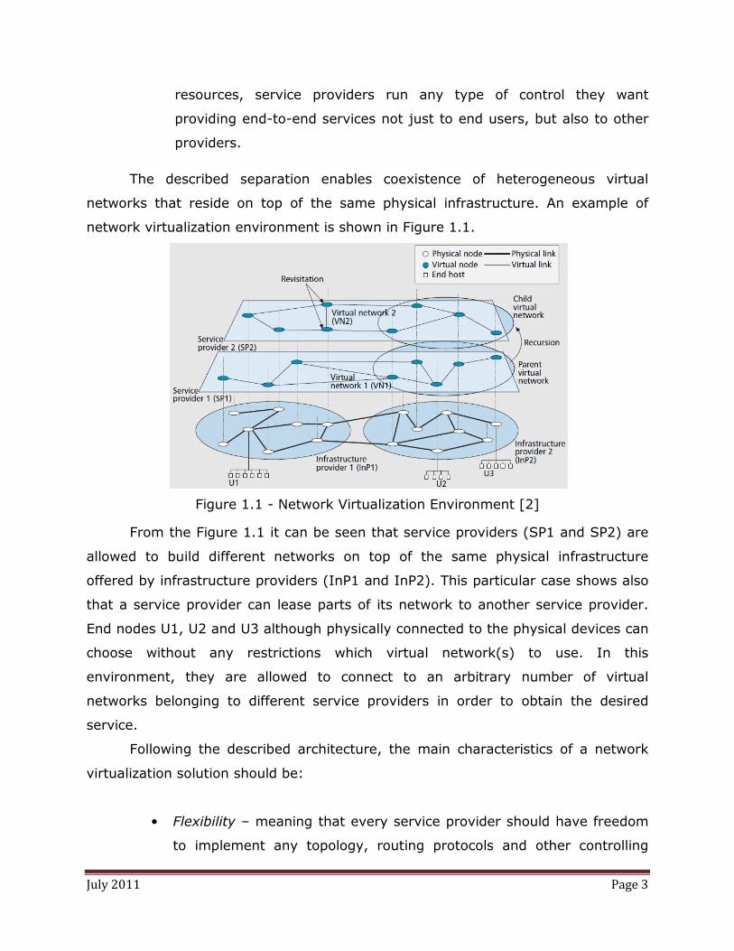
The described separation enables coexistence of heterogeneous virtual
networks that reside on top of the same physical infrastructure. An example of
network virtualization environment is shown in Figure 1.1.
Figure 1.1 - Network Virtualization Environment [2]
From the Figure 1.1 it can be seen that service providers (SP1 and SP2) are
allowed to build different networks on top of the same physical infrastructure
offered by infrastructure providers (InP1 and InP2). This particular case shows also
that a service provider can lease parts of its network to another service provider.
End nodes U1, U2 and U3 although physically connected to the physical devices can
choose without any restrictions which virtual network(s) to use. In this
environment, they are allowed to connect to an arbitrary number of virtual
networks belonging to different service providers in order to obtain the desired
service.
Following the described architecture, the main characteristics of a network
virtualization solution should be:
• Flexibility – meaning that every service provider should have freedom
to implement any topology, routing protocols and other controlling

July 2011 Page 4
mechanism on the resources it has leased from infrastructure provider.
Implemented control should not be restricted neither by underlying
physical infrastructure, nor by other virtual networks.
• Programmability – meaning that service provider should be able to
implement customized controlling protocols on leased infrastructure.
Programmability is indeed the enabling tool for the previously
described flexibility.
• Scalability – meaning that the number of virtual networks should not
be the limiting factor of the system. InP-s must scale to support
increase in number of virtual networks without affecting their
performance.
• Isolation – meaning that different virtual networks should be isolated
from each other such that operation of one does not affect the others.
This is especially important in cases of erroneous operation of a virtual
network.
• Heterogeneity – that can be divided into two categories: heterogeneity
with respect to underlying technologies and heterogeneity with respect
to virtual networks on top of these technologies. The former supposes
that various technologies comprising physical infrastructure should not
affect network virtualization process, while the latter specifies that
many heterogeneous virtual networks should be able to coexist.
• Legacy Support – supposes dealing with the question of backwards
compatibility which is very important every time when implementation
of new technologies is considered. This means that current Internet
network should be supported in the Network Virtualization
environment.
Specified like this, network virtualization looks as a perfect solution for
building testing infrastructure for future networks. Nevertheless, since it is a broad
topic with many possible approaches only some aspects of network virtualization
will be considered in this work. The next section briefly outlines these aspects,
together with the motivation for their choosing.
July 2011 Page 5
1.2 Main Objectives of this project
Being present for some years, the concept of network virtualization has
gained a lot of research attention resulting in many virtualization solutions. Some of
them are well known (VLANs, VPNs, Planet Lab), some are still being developed
(GENI, AKARI, CABO) but not all of them completely follow the above-described
characteristics. Most of network virtualization solutions are designed for specific
network technology (e.g. IP or SDH) or for specific layer (link, network or physical
layer). The comprehensive overview of network virtualization solutions can be
found in [2], while the focus of this work will be on presenting OpenFlow as an
enabling tool for full heterogeneous virtualization. Virtualization with OpenFlow has
been chosen since it is a relatively new approach which has recently gained a lot of
interest within the IT community. Its ability to be applied in both packet and circuit
networks as well as to provide flexible control, have been a good motivation to
explore the possibilities it opens. In line with this, the rest of material is organized
in the following manner.
Introductory Chapter 1 is followed by first part of this thesis, Part I. In the
chapters 2-5, Part I deals with OpenFlow in packet networks. Chapter 2 introduces
the main concepts of OpenFlow: architecture, features and working principles while
Chapter 3 explains centralized control on top of OpenFlow. In Chapter 4, FlowVisor
will be described as a network virtualization tool based on OpenFlow. Considering
OpenFlow features laid down in Chapters 2-4, in Chapter 5 we have investigated
the possibilities of implementing distributed control on top of OpenFlow devices. As
a result of that, some advantages of distributed control implementation have been
pointed out together with its main problem. With this contribution, theoretical
discussion about OpenFlow in packet networks has been rounded closing the Part I.
Part II, in Chapters 6-8, extends OpenFlow to circuit switching networks showing its
abilities and limitations in the environment traditionally different from its original
one – the packet switching networks. Chapter 6 will discuss OpenFlow circuit
switches and their role in unification of packet and circuit switching networks using
OpenFlow. Besides this, it will contain our proposal of the network architecture for
interoperability between GMPLS and OpenFlow. Chapter 7 will provide our

July 2011 Page 6
investigation and conclusions on virtualization of Optical Networks using OpenFlow
and FlowVisor. By reusing the concepts from Chapter 4, applicability of FlowVisor to
OpenFlow-enabled optical nodes will be examined. Experimental part of the work
done in this thesis is sublimed in Chapter 8, representing familiarization with
OpenFlow packet switches and corresponding networks, in order to contest some
of the concepts laid down in Part I. Conclusions derived from presented material,
will be provided in Chapter 9 together with the proposals for future research.

July 2011 Page 7
PART I – OPEN FLOW
2. Programmable Packet Switches
In their attempt to fight with lack of experimental facilities for testing of new
research solutions, a group of researchers and visionaries from Stanford University
(SU) has recognized the importance of making open infrastructure which will be
used for running experiments within university campuses. Considering that most
campuses have networks based on Ethernet switches/routers, they have decided to
create programmable Ethernet switches. Taking into account that realistic
experiments require production traffic and environment, they have decided to run
experiments on production network devices alongside production traffic.
Nevertheless, experimenting on a production network raises several questions such
as:
• How to separate experimental from production traffic?
• How to allow researchers to control just their portion of experimental
traffic?
• Which functionality is needed to enable experimenting on a production
network?
One answer to these questions could be to force equipment vendors to open
their equipment by implementing programmable software platforms. In this way
both administrators and researchers would have what they need. Researchers could
program the switches through the interface provided by the vendor. This would not
cause any problem to production traffic so network administrators would have
nothing to worry about. Naturally, vendors are reluctant to give away their
technologies and proprietary algorithms in which they have invested a lot of money.
Moreover, by opening their boxes they are reducing the entry-barrier for

July 2011 Page 8
competitors and put their profit at risk. Consequently, this scenario is not likely to
happen in a foreseeable future.
The second solution could be to use one of the existing open platforms.
Unfortunately they lack in performance, port number or both. For example: a
simple PC offers several interfaces and an operating system over which applications
can be written to process packets in any way (full controlling flexibility). The
problem is that PC does not support a hundred or more ports needed in campus
networks and 100Gbps processing speed (PC offers up to 1Gbps). Another example
is NetFPGA, low cost user programmable PCI card which supports line rate
processing but has only 4 Gigabit Ethernet ports [4]. An ATCA-based programmable
router is a research project that satisfies both requirements, offering full
programmability, but currently is too expensive for widespread use [5].
Having in mind that commercial solutions, which offer full programmability,
do not satisfy performance requirements and research solutions (that also offer full
flexibility in packet control) that provide good performance are too expensive, the
researchers from SU have decided to trade off controlling flexibility for price
reduction [6]. Their solution, named Open Flow switch, has been designed to
provide:
• Reasonable experimenting flexibility – rather than full controllability,
aim was to provide several operations which will offer reasonable
flexibility in control.
• Low cost and high performances – without low prices it is impossible
to deploy these devices in campus networks. However, the cost
limitation should not degrade performance.
• Isolation of experimental traffic from the production traffic –
cohabitation of production and experimental network greatly depends
on isolation between them. It is clear that production traffic must be
well-protected against error prone experiments and tests conducted
on experimental traffic.
• Support of the black box concept – all mentioned requirements should
be realized without revealing internal structure of the switch. This is

July 2011 Page 9
the only way in which vendor’s could agree to discuss implementation
of any changes on their equipment.
The enlisted four requirements are cornerstone characteristics of Open Flow
switch, which is described in more details in the next section of this chapter.
2.1 Open Flow Switch
In today’s networks, Ethernet switches are used to connect different Local
Area Networks (LANs). Their task is to forward Ethernet frames according to their
Media Access Control (MAC) addresses. From the functional point of view Ethernet
switches can be divided into a data plane and a control plane. The data plane
represents a forwarding table according to which packets coming to an Ethernet
switch are forwarded. Forwarding tables consist of entries which tell to which output
port received Ethernet frames should be sent. Populating of forwarding table with
these entries is the task of the control plane. The control plane is a set of actions
exerted on received Ethernet frames to decide their destination ports. In order to
quickly perform frame processing, these actions are implemented in hardware
together with the forwarding table. This architecture, depicted on the left side of
Figure 2.1, is known as the integration or coupling of data and control path (plane)
and represents the main characteristic of today’s Ethernet switches. Coupled data
and control plane provide fast execution of actions specified in the control plane,
but does not offer any flexibility in control. In this environment, changing of control
plane action would require hardware redesign and reintegration which is not flexible
at all.
In order to provide more controlling flexibility, the OpenFlow switch is
designed as a generalization of an Ethernet switch with two big changes: separation
of control and data plane and data plane abstraction using OpenFlow tables.
The main idea of the OpenFlow is moving of control plane outside the switch.
This is done in order to enable external control of the data plane through a secure
channel. However, Ethernet switches are produced by many vendors and
consequently their realizations differ a lot. Separation of control and data plane

July 2011
results not just in external control
want, but also in a number of different data plane realizations. In order to be able
to apply Open Flow vendor
abstraction of the data plane. To be general enough, this abstraction should contain
only those things that are common for majority of switches. Luckily, although
switches from different vendors differ a
forwarding table. Consequently, Open Flow switches use Flow Tables to represent
forwarding tables (data planes)
Figure 2.1 – Non-OpenFlowcontrol path (left) and OpenFlow Switch architecture Table and Controller, communicating over SSL using OpenFlow Protocol (right)
Altogether, an Open Flow Switch comprises the fol
are also shown on right side of
• Flow table – that represents data plane of the switch. Structurally, it is
a set of entries used to forward packets. From architectural point of
view, it is a generalization of
abstraction of data plane offered to remote cont
purposes.
• Remote Controller
simple PC, server or any other kind of machine
software defined by a researcher. The remote controller defines the
behaviour of the sw
table. This is done mainly by adding or deleting entries.
• Secure Channel
controller and the flow table. It uses Open Flow Protocol which
results not just in external controller on which we can run any type of control
number of different data plane realizations. In order to be able
dor-independently, it is necessary to make a simple
abstraction of the data plane. To be general enough, this abstraction should contain
only those things that are common for majority of switches. Luckily, although
switches from different vendors differ a lot, they all have one common thing, the
forwarding table. Consequently, Open Flow switches use Flow Tables to represent
forwarding tables (data planes) of various switches.
OpenFlow Ethernet switch architecture with unified data and OpenFlow Switch architecture with separated Opencommunicating over SSL using OpenFlow Protocol (right)
Open Flow Switch comprises the following components
on right side of Figure 2.1:
that represents data plane of the switch. Structurally, it is
a set of entries used to forward packets. From architectural point of
view, it is a generalization of an Ethernet switch’s flow table,
abstraction of data plane offered to remote controller for controlling
Remote Controller – represents control plane of the switch. It can be a
server or any other kind of machine running control
software defined by a researcher. The remote controller defines the
of the switch by manipulating with entries inside the flow
table. This is done mainly by adding or deleting entries.
Secure Channel – is used for communication between the remote
controller and the flow table. It uses Open Flow Protocol which
Page 10
ler on which we can run any type of control we
number of different data plane realizations. In order to be able
, it is necessary to make a simple
abstraction of the data plane. To be general enough, this abstraction should contain
only those things that are common for majority of switches. Luckily, although
lot, they all have one common thing, the
forwarding table. Consequently, Open Flow switches use Flow Tables to represent
Ethernet switch architecture with unified data and separated OpenFlow
communicating over SSL using OpenFlow Protocol (right)
lowing components, which
that represents data plane of the switch. Structurally, it is
a set of entries used to forward packets. From architectural point of
Ethernet switch’s flow table, i.e. an
roller for controlling
represents control plane of the switch. It can be a
running control
software defined by a researcher. The remote controller defines the
itch by manipulating with entries inside the flow
is used for communication between the remote
controller and the flow table. It uses Open Flow Protocol which

July 2011 Page 11
specifies format of the messages exchanged between the flow table
and controller.
Prior to describing OpenFlow’s building blocks in more details, it is important
once more to emphasize changes that OpenFlow has brought into Ethernet
switches. Instead of having coupled control and data plane able to perform only one
type of control, OpenFlow has separated the two planes. Moreover, it has
abstracted the data plane with the Flow Table and offered it to the remote
controller over the secure channel. In this manner, controlling has become
completely independent of underlying data plane allowing much more flexibility.
Flow Table
As previously stated and represented in Figure 2.2, flow table is a set of
entries. Each entry in the table has:
• Header field - which is used for packet matching
• Counter field - which is used for statistical purposes
• Action field - stating one or more actions associated with a packet
matched against an entry.
Figure 2.2 - Flow Table with entries comprising headers actions and counters
Every packet processed by an OpenFlow switch, must be compared against
the entries in the flow table. If a match is found, specified action is taken (e.g.
forward to a specific port). Otherwise, packet is forwarded to the controller which
defines further steps according to the routing algorithm.
July 2011 Page 12
However, although OpenFlow switch provides per packet processing at a line
rate, for the sake of performance it cannot provide per packet control. Namely, by
decoupling control plane from the data plane, the ability to process control actions
quickly has been lost. This means that controlling actions cannot be calculated for
every packet. Instead of this, according to different options found in the header
field, packets are grouped into flows and controlled as flows. Namely when a packet
from a new flow comes to an OpenFlow switch, it is forwarded to the controller. The
controller determines how the packet should be forwarded and puts that
information in a new entry. The entry is added to the flow table where it is used for
the further packet look up. Every following packet from the same flow will be
forwarded according to the added entry without forwarding to the controller. In this
manner, OpenFlow switch has traded controlling flexibility for controlling
granularity. Instead of per packet control and zero control flexibility found at non-
OpenFlow Ethernet switches, an Open Flow switch has some of both properties. In
this way the first requirement from the Chapter 2 has been fulfilled. Nevertheless,
the described trade-off has introduced a new important concept, a packet flow.
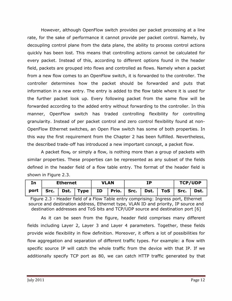
A packet flow, or simply a flow, is nothing more than a group of packets with
similar properties. These properties can be represented as any subset of the fields
defined in the header field of a flow table entry. The format of the header field is
shown in Figure 2.3.
In
port
Ethernet VLAN IP TCP/UDP
Src. Dst. Type ID Prio. Src. Dst. ToS Src. Dst.
Figure 2.3 - Header field of a Flow Table entry comprising: Ingress port, Ethernet source and destination address, Ethernet type, VLAN ID and priority, IP source and destination addresses and ToS bits and TCP/UDP source and destination port [6]
As it can be seen from the figure, header field comprises many different
fields including Layer 2, Layer 3 and Layer 4 parameters. Together, these fields
provide wide flexibility in flow definition. Moreover, it offers a lot of possibilities for
flow aggregation and separation of different traffic types. For example: a flow with
specific source IP will catch the whole traffic from the device with that IP. If we
additionally specify TCP port as 80, we can catch HTTP traffic generated by that

July 2011 Page 13
device. The same thing can be done for any other type of traffic which is always
expected at certain port.
Using the header format from Figure 2.3, when a packet comes to an Open
Flow switch it is parsed and compared against the headers of all entries in the flow
table. Matching algorithm follows the header structure from the Figure 2.3 and goes
as it is presented in the flowchart shown in Figure 2.4.
After packet parsing, as a first step, the ingress port, Ethernet source and
destination addresses as well as Ethernet type are set. All other fields in the format
from the Figure 2.3 are zero. The Ethernet type is first checked against value
0x8100. If the match exists VLAN ID and PCP fields are added to the header and
used for the look up. If this is not a case Ethernet type is checked against 0x0800
to see if an IP packet is carried by the Ethernet frame. In the case of matching, IP
source and destination address are added and used for table look up. Between
these two steps, optionally, ARP check can be done. After IP, the next performed
check is fragmentation check, i.e. if the IP packet is fragmented or not. In the case
of no match, packet is looked up normally while in case of yes additional checks are
provided. First is run check for transport layer protocol (UDP and TCP) and after
that a check for ICMP protocol. For the former, UDP/TCP source and destination
ports are included in the header while for the latter ICMP type and code fields are
added. Header generated in this way is checked against all entries in the flow table
[7].
If the match exists, action specified inside the action field of the matching
entry is taken. Specification of the OpenFlow switch provides only minimal number
of actions that has to be supported. List of actions can be extended, but this should
be done with a lot of consideration. The list of supported actions has been chosen
small such to provide reasonable amount of flexibility and generality [6]. In this
manner price of the equipment is kept low, satisfying the second basic requirement
of Open Flow switch (Chapter 2) and providing applicability to almost all available
switches on the market. By extending the list of actions, generality could be
jeopardized because Ethernet switches are very diverse and do not share a large
group of common functions.

July 2011 Page 14
Figure 2.4 - Matching algorithm for packet checking against the flow table [7]
Nevertheless, all actions that an OpenFlow switch can perform are divided
into Required Actions and Optional Actions. As the names say, required actions
have to be implemented in every OpenFlow switch. Depending on optional actions
they implement, OpenFlow switches can be divided into two categories: dedicated
OpenFlow switches and OpenFlow enabled switches. The architecture of these two
types of switches is shown in Figure 2.5.

July 2011 Page 15
Figure 2.5 - Dedicated OpenFlow Switch (left) vs. OpenFlow Enabled Switch (right)
• Dedicated OpenFlow switches – support only required actions.
Required actions are:
� Forwarding of packets to a specific port physical port - in order to
provide forwarding across the network.
� Forwarding of the packets to the following virtual ports: ALL – to all
ports except for the incoming, IN_PORT – only to the input port,
LOCAL – to the switch’s local networking stack (used for bypassing
of the remote controller and direct control of the switch), TABLE –
perform actions from the flow table and can be applied only to the
packets sent from the controller and CONTROLLER – encapsulation
and forwarding of the packet to the remote controller. This is
usually done for the first packets in a flow, so called flow initiations,
in order to decide whether a new entry should be added.
� Discarding of packets – in order to be able to deal with broadcast
traffic or denial of service attacks.
However, as it can be seen, this switch does not have any mean to provide
normal switch processing. It only executes control instructions from the remote
controller. Because of that, up to today, dedicated OpenFlow switches have not
found any significant practical importance.
• Open Flow Enabled Switches – besides all required actions, support
also the optional action “forward to the virtual port NORMAL”. This represents
forwarding of the packets through the switch’s normal L2/L3 processing.
Considering this, an OpenFlow enabled switch can be seen as a commercial

July 2011 Page 16
Ethernet switch enhanced with the OpenFlow features by implementing Flow Table
and OpenFlow Protocol. The flow table implemented in this switch re-uses the
existing hardware while OpenFlow protocol runs on switch’s operating system. This
suggest that implementation of OpenFlow to the existing switches should not cause
any hardware changes and thus can be done relatively easy and inexpensively,
while preserving the black box concept. With this, it is clear that Open Flow Enabled
Switches satisfy the fourth requirement from the list in the Chapter 2.
The only requirement that is left and needs to be taken care off is the clear
separation between production and experimental traffic. Namely, as OpenFlow
Enabled switch can process incoming packets both as a “normal” and a researcher-
defined switch, we need a clear separation between traffic that is processed with
the normal (production traffic) and with the researcher-defined switch
(experimental traffic). In the most primitive way, this can be done by network
administrator who can tag production and experimental traffic with different VLAN
ID-s. In this manner, the two can be easily separated by flow aggregation. In
practice this is done in different way outside OpenFlow, as it will be shown in the
Chapter 4. Disregarding this for a moment and thinking about VLAN tagging as a
traffic separation tool, it is clear that Open Flow Enabled switch fulfils all
requirements necessary for achieving flexible but affordable control.
Nevertheless, although all needed requirements can be implemented just
with the optional action “forward to the virtual port NORMAL”, Open Flow specifies
some additional optional actions. These actions can be used to increase
management abilities of the remote controller defined on top of Open Flow Enabled
Switch. They are:
• FLOOD – action that performs packet forwarding according to the
spanning tree protocol
• MODIFY FIELD –action that allows changing of different header fields.
This action can increases usefulness of the open flow very much. A
possible application of this action is implementation of NAT tables.
An OpenFlow switch reports the list of supported action to the controller when
connecting to it for the first time.

July 2011 Page 17
Eventually, besides header and action field, a flow table entry consist also a
field used for statistical purposes. It comprises a set of counters which are used to
statistically describe operation of an OpenFlow switch. By observing these counters
controller is able to monitor performance of the switch. Information obtained from
these counters is used mainly for management decision making. These counters, as
well as all other information kept in Flow Table, are communicated to the remote
controller over the secure channel.
2.1.1 Secure Channel
Secure Channel is the interface that connects OpenFlow switch to the
controller, Figure 1.1. Interface between the switch’s datapath and secure channel
is implementation specific, but formats of all messages transferred across the
secure channel must conform to the formats specified by OpenFlow Protocol [7].
OpenFlow protocol specifies three types of messages: controller to switch
(generated by the controller), asynchronous (generated by the switch) and
symmetric (generated at both sides, without need for solicitation).
Controller-switch messages are generated by the controller in order to manage
or inspect the state of the switch. They include:
• Feature messages - request and reply feature message through which
controller learns about switch’s capabilities
• Configuration messages – that are used to query or set configuration
parameters of the switch
• Modify State messages – that are used for addition/removal of the
flows in the flow table
• Read State messages – that are used to collect statistics from the flow
tables, ports or individual entries
• Send Packet messages – that are used to send a packet out specified
port on the switch
• Barrier messages - that are used to ensure that dependencies between
different messages have been met.

July 2011 Page 18
Asynchronous messages are sent by the switch without controller soliciting for
them. Four main messages of this kind are:
• Packet-in message – that is sent when there is no matching entry or
matching entry’s action specifies forwarding to the controller. If switch
supports buffering, it usually buffers the packet and forwards only part
of the header together with buffer ID. Otherwise, whole packet is
forwarded to the controller.
• Flow removed message – signalizes that a flow has been deleted as a
result of timeout.
• Port status message - reports port status change to the controller, no
matter whether it was asked for or not.
• Error message - notifies the controller that error has occurred
Symmetric messages are messages that can be sent by both sides without
solicitation. They include:
• Hello message – that is sent by both controller and switch immediately
after the connection set up. Using these messages, both sides send the
version of the Open Flow protocol that they support in order to
negotiate the highest version which is commonly supported.
• Echo messages – are sent to collect the parameters of the connection.
However, they are also used to keep alive the connection between the
switch and the controller.
• Vendor messages – that provide a standard way for offering additional
functionality to the vendor.
With Flow Table and Secure Channel described, the only part of the
OpenFlow Switch left to discuss is the Remote Controller. Nevertheless, OpenFlow
has been designed to offer flexibility in controlling so it does not specify any
particular controller on top of the OpenFlow switches. Consequently, Flow Table and
Secure Channel discussion rounds the description of OpenFlow protocol. With
respect to that it should be clear that OpenFlow protocol is nothing more but a

July 2011 Page 19
communication protocol that enables some controlling flexibility by introducing
architectural changes in packet switches. It is a set of messages which supports
external control of switches. The controller choice is not part of the OpenFlow and it
is left to the administrators and researchers. With respect to this, two different
possibilities in controlling of OpenFlow switches will be discussed in the next
chapter (centralized control) as well as in Chapter 5 (distributed control).

July 2011 Page 20

July 2011 Page 21
3. Remote Control in Open Flow-enabled Networks
On top of Open Flow switches, administrators and researchers have a
freedom to implement any type of control. The only constraint they have is in the
number of actions that can be used to control the switches. As it is mentioned in
the previous chapter, Open Flow specifies only limited number of controlling actions
divided into required and optional actions. Nevertheless, these actions can be used
to build centralized as well as distributed control on top of Open Flow switches. In
this chapter, Network Operating System (NOX) will be presented as an existing
solution for the centralized control.
3.1 Centralized Control in Open Flow Networks
In the second chapter it has been shown that is possible to run experimental
traffic on existing Ethernet switches alongside with production traffic. All that has
been provided at relatively low cost while preserving black box concept and
isolating experimental from production traffic.
However, the original goal of the Open Flow has been to provide an
environment which will allow two things: easy writing of control applications as well
as their testing. Open Flow switches have made possible testing of control
applications. The other part of the initial task, the easy writing of applications
should be provided by controller. Hence, the goal is to create an Open Flow network
management tool which will allow easy writing of control applications. For this
purpose the researchers from Stanford University have designed a centralized Open
Flow controller, the Network Operating System or shorter NOX [8]. Compared with
network management solutions found in today’s networks, NOX represents a shift
in network management approach.
Namely, in today’s networks, network management is done as low level
configuration that requires a lot of knowledge about underlying physical equipment.
Controlling applications of today’s management tools have to deal with different
kind of addresses (MAC, IP addresses…), a lot of topology information and so on.

July 2011 Page 22
For example: in order to block a user, the knowledge about its IP address is
needed. For more complex tasks more knowledge about the network is needed.
Consequently, it is clear, that this programming environment will not lead to
blossoming of network controlling applications. However, this situation looks very
similar to a problem that has been already seen (and solved) in the engineering
world.
As it is well known, in the early days of computers, programs were written in
machine languages which did not provide any abstraction of physical resources.
This has meant that programmers needed to take care of resource allocation,
management and so on. Consequently, programs were difficult to write and
understand. When introduced, operating systems provided programmers with an
abstraction of physical resources (memory, processor, communication) and
information (files and directories) allowing them to efficiently solve complex
problems on different machines.
Comparing the two, it is obvious that today’s networks are “computers
without an operating system” [8]. Considering this, NOX has been introduced as a
kind of operating system for Open Flow networks. Although it has operating system
in its name, NOX is more a programmable interface. Namely, the only thing that
NOX does is abstraction of the underlying resources. Speaking about resource
abstraction, it is very important to distinguish between abstraction done by
OpenFlow and the one done by NOX. OpenFlow abstracts resources of a switch, a
single network element, while NOX abstracts resources of a whole network.
Unlike, computer operating systems it does not perform any resource
management. Management or controlling of resources (in this case Open Flow
switches) is done solely by application residing on top of NOX. NOX only gathers
network information and out of them builds simplified network view which offers to
the controlling applications as a centralized network representation. Hence, the
precise description would be that NOX is a uniform and centralized programmable
interface to the entire underlying Open Flow Network. To provide its main goal,
easy writing of controlling applications, NOX is based on following two properties:

July 2011 Page 23
• Applications running on network OS should have centralized
programming model, i.e. they should be written as if the network were
a single machine. To provide this, centralized network state needs to
be created.
• Network OS should provide applications with highly abstracted physical
topology view. This means that instead of IP and MAC addresses,
applications will work with host and user names. In order to achieve
this, mappings between abstracted view and physical parameters need
to be updated constantly and regularly.
These two features represent the shift in management approach that has
been introduced at the beginning of the section. Instead of IP and MAC addresses
as well as port numbers, controlling applications are written with highly abstracted
host and user names. Moreover, network information is gathered by a single
centralized device unlike today’s management systems where many devices gather
local information and exchange them over complex distributed protocols. This shift
from distributed to centralized approach clearly makes application writing a lot
easier. However, it also brings some limitations and trade-offs that will be explained
in the next section.
3.1.1 NOX Components
Components of a NOX-based network are depicted in the Figure 3.1. The
system comprises several OpenFlow switches that are managed by a NOX controller
running on one or more network attached servers. On these servers run NOX
software and management (control) applications. NOX software includes several
control processes as well as applications used to build and update unified network
view. The network view is kept in a database. It is created by observing the
network and offered to controlling applications running on top of NOX. All
controlling decisions made by the applications are used to modify flow tables in the
Open Flow switches and in that way manage the network.

July 2011 Page 24
Figure 3.1 - Components of a NOX-based network: Open Flow switches, Server with NOX controller and Database with Network View [8]
One of the main components of the NOX-based network is Network View.
Making of centralized network state is the main technical issue in NOX. Knowing
that Network View is created by network observation, observation granularity is a
very important system design issue. It is obvious that large number of real time
changing parameters originating from large number of switches cannot be part of
the network view. A single device cannot process all these parameters and keep the
network view regularly updated. Trade-off between scalability and management
flexibility is needed. Inclusion of larger number of network parameters, that change
really fast, provides a lot of information about the network and its state. The more
management information is available, the more controlling flexibility will be offered
to management applications. In simple words, the more network parameters are
available through the network view, the wider range of applications could be
created. On the other hand, this limits scalability because all those information from
large number of nodes cannot be maintained fast enough. By maintaining of
Network View it is meant that network view should be updated regularly as well as
mappings between abstractions used by applications and low level network
parameters. Taking this in mind, observation granularity in NOX based networks
has been chosen such that network view contains:

July 2011 Page 25
• Switch level topology
• Locations of users, hosts, middle-boxes and other network elements
• Services being offered (HTTP, NFS etc.).
The scalability of the chosen network view is relative since it also depends on the
complexity of controlling applications build on top of it. Hence, it is impossible to
state explicitly how many switches a specific network view will be able to handle.
Nevertheless, the chosen network view is able to provide adequate input for many
network management tasks [8]. Information that it includes changes slowly and
provides scalable maintenance in large networks. Justification for this choice of
observation granularity can be the timing requirements. Considering them:
• Packets arrive at the rate of ten millions per second for 10Gbs
Ethernet link.
• Flow initiations arrive at the rate one or two orders of magnitude lower
than packets.
• Network view, as specified above, experience approximately 100
changes per second.
By keeping packets and flows out of the consistent network view they can be
processed in parallel. In this situation, a packet arriving to a switch is processed
independently of a packet arriving to another switch. Hence each switch can
process packets by keeping their state locally. Same thing stands for flow
initiations. No matter to which control process flow initiation is forwarded, the
controlling result will be the same. Consequently, the flow initiations can be
processed in parallel by many different control processes since all of them share the
same network view. This is very important for scalability because new control
processes can be introduced by adding new servers.
Besides observing granularity needed for setting up the network view, there
is also an issue with controlling granularity. The controlling granularity specifies
which actions controllers can use to enforce calculated controlling decisions. Unlike
observing granularity which introduces some design decisions in NOX, controlling
granularity is defined by underlying Open Flow switches. A set of required and

July 2011 Page 26
optional actions they offer to the controller (Chapter 2.1), defines controlling
granularity. In addition to this difference, it is worth noticing that controlling
granularity is a result of low price and generality vs. controlling flexibility trade-off,
while observing granularity comes from scalability vs. controlling flexibility trade-
off.
With both observing and controlling granularity specified, the network view is
rounded up. The only thing needed is to present it somehow to the controlling
applications. The interface that bridges network view and controlling application is
described in the next section.
3.1.2 NOX Programmatic Interface
Programmatic interface specifies two things:
• Information that NOX offers to programmers/researchers/network
administrators such that they can program controlling applications
• Means that programmers can use to modify the network view.
Conceptually NOX’s programmatic interface is very simple. It revolves around
events, a namespace and the network view [8].
Events – Network is a dynamic system in which some changes always occur
(attachment/detachment of a node, link fail etc). NOX applications deal with these
changes by utilizing event handlers which are registered to execute when a specific
event occurs. The event handlers are executed according to their priority (set up
during registration) and their return value indicate to NOX whether the event
execution should be stopped or the event should be passed to the next registered
handler. Events can be generated by both OpenFlow messages (packet in, switch
join, switch leave, statistics received) and NOX applications by processing low level
events or other applications’ events.
Network view and namespace – Network view and namespace are
constructed and maintained by a set of control applications so called base
applications. These applications perform user and host authentication and conclude
host names by using DNS. High level names which are bound to the host names
July 2011 Page 27
and low level addresses allow topologically independent writing of applications.
Conversion between the two can be done by “compiling” high level declarations
against the network view in which manner low address look-up functions are
produced. Considering that high consistency of network view is a must do,
applications write to the network view only when a change is detected in the
network.
With these three means, programmers are enabled to write applications
whose results will be controlling commands to the underlying OpenFlow switches.
According to the OpenFlow architecture and concepts controllers are allowed to
read/delete entries from the flow table and obtain statistics by reading counters
within an entry. In this way full control over L2 forwarding is achieved as well as
packet header manipulation and ACLs (Access Network List).
Specified like this, NOX today represents the most popular and widely used
controlling interface for Open Flow devices. By sacrificing some controlling flexibility
and allowing parallel control processes on top of consistent network view, it has
succeeded to gather enough scalability for deployment in small networks, such as
university campuses. For example, Stanford University has been running their
production network on NOX controlled Open Flow switches for two years [8], [9].
Many other Open Flow islands, all around the world, are being created with NOX
interface on top of them.
However, everything described so far, including Open Flow and NOX
controllers, assumed only one type of control on top of our testing infrastructure.
Principally, Open Flow can support various types of controllers, but from its point of
view not simultaneously. Consequently Open Flow is not a network virtualization
tool, i.e. it cannot provide several virtual networks on top of OpenFlow switches.
However, although not being by itself a network virtualization tool, it is a quite
powerful tool for its enabling. The next chapter will introduce FlowVisor as a
network virtualization tool inextricably bounded to OpenFlow.

July 2011 Page 28

July 2011 Page 29
4. FlowVisor
FlowVisor is a network virtualization tool whose aim is to allow coexistence of
multiple, diverse and mutually isolated logical networks on top of same physical
infrastructure [9]. In terms of testing of research ideas, this is necessary in order to
allow multiple researchers to conduct their experiments simultaneously and
independently of each other.
In order to better understand FlowVisor’s architecture and functional units,
basic principles of computer virtualization will be shortly introduced. In computer
virtualization, the instruction set provides abstraction of hardware resources. On
top of it, some virtualization tool (e.g. Xen) performs slicing and sharing of
abstracted physical resources. In this manner different guest operating systems can
be supported on top of same physical infrastructure. This is depicted in the left part
of Fig. 4.1.
Similarly, FlowVisor as a network virtualization tool also requires some kind
of hardware abstraction. The abstraction should be easy to slice and general
enough to encompass various devices. Considering that OpenFlow fulfils these
requirements it has been chosen as a hardware abstraction tool on which FlowVisor
is based. Consequently, it is now clear why at the end of previous chapter
OpenFlow has been described as an enabling tool for network virtualization.
Having the OpenFlow as its enabling tool, FlowVisor collocates itself in
between the OpenFlow and remote controllers. Its job is to slice provided
abstracted hardware (Open Flow tables) such that it can offer isolated infrastructure
portions to the controllers above itself. Prior to considering how FlowVisor does this,
it is necessary to specify which resources need to be abstracted and sliced within
network virtualization process.
As it is shown in Figure 4.1, network virtualization is nothing more but the
virtualization of network resources. While in computer systems Central Processing
Unit (CPU), memory and input/output interfaces are virtualized, network

July 2011 Page 30
virtualization requires abstraction of: traffic, topology, forwarding tables, switch
CPU time and bandwidth.
Figure 4.1 - Architecture of computer virtualization environment (left) compared with the architecture of network virtualization environment (right) emphasizing
basic building block of general virtualization tool (centre) [9]
Selection of resources that should be abstracted is based on the fact that
abstraction should provide only the necessary information about a network. In
every representation of a network, its topology and traffic are inevitable factors.
Bandwidth (data rate) is needed for traffic transportation while forwarding tables
and switch CPU time are selected based on forwarding mechanism provided by
OpenFlow switches. Virtualization of these resources means that every logical
network provided by the FlowVisor should have its own topology, traffic, bandwidth,
forwarding tables and switch CPU time. As, previously said, the first step in this
virtualization is hardware abstraction and it is performed by OpenFlow. It offers
flow tables as representations of switches and flows as abstraction of traffic. How,
with this inputs, FlowVisor succeeds to virtualize a network over the five mentioned
dimensions (traffic, topology, bandwidth, forwarding tables and switch CPU time) it
will be shown in the next sections of this chapter.
July 2011 Page 31
4.1 Design goals
Main design goals of Flow Visor are:
• Flexible definition of virtual networks – since there is no clear idea
what do we need on top of our physical infrastructure, resource
allocation and sharing should be flexible enough to support creating of
highly diverse virtual networks. Virtualized networks are supposed to
be used for testing of new controlling solutions, so it is of utmost
importance that they can be allocated with arbitrary topology, amount
of bandwidth, traffic, switch CPU time and forwarding table entries.
• Transparency - Both controllers and physical layer should not be aware
of virtualization layer. A controller should act as it controls the whole
network, while the network should act as it has only one controller on
top of it. This is important for two reasons. Firstly, network controllers
should be designed on top of realistic topologies. By being aware of
virtualization layer they are being designed for virtualization
environment, not for the underlying real topology. Secondly, the aim
of network virtualization is flexibility in control, which can be achieved
only by maximal possible decoupling of control plane from anything
residing below it. Consequently, virtualization layer should be
transparent to controllers and network hardware.
• Isolation – existence of multiple virtual networks is not a significant
achievement unless they are securely isolated from each other. Only in
that case they can be independent and only than it is possible to speak
about multiple networks coexisting on top of same physical
infrastructure.
Fulfilling of these three goals, at the first look, does not satisfy all the
requirements of network virtualization tool that were laid down in the Chapter 1.1.
Out of specified six characteristics FlowVisor by itself provides only: isolation and
flexibility. Programmability, heterogeneity, scalability and legacy support are

July 2011 Page 32
provided by OpenFlow while FlowVisor with its transparency only keeps them intact.
Namely, programmability is provided by the OpenFlow through the support of every
type of control that can be built with the specified controlling actions (Chapter 2.1).
Scalability is the matter of controlling solution but the only solution specified so far
(NOX controller platform) has taken it into account as a part of network view
(Chapter 3.1.1). Heterogeneity and Legacy support are provided by OpenFlow’s
generality, i.e. its ability to be implemented on wide variety of switches (Chapter
2.1). Consequently, it is clear that OpenFlow plays a huge role in FlowVisor’s ability
to act as a network virtualization tool. With the task and roles of FlowVisor and
OpenFlow clearly specified and separated, it is time to describe how FlowVisor
performs its part of duties.
4.2 Working principle and architecture
Figure 4.2 - FlowVisor architecture and functional units
As it is depicted in Figure 4.2, FlowVisor has three functional entities:
Resource Allocation Policy, Translation and Forwarding [9]. Residing on top of Open
Flow, it only sees OpenFlow tables as abstractions of physical switches and flows as
abstractions of traffic. These two together with bandwidth, topology and switch CPU
time are partitioned by Resource Allocation Policy entity and assigned to different
controllers. In this manner FlowVisor create slices keeping at the same time each

July 2011 Page 33
slice’s policy. Slice policies are descriptions of virtual networks and they contain
information such as which traffic or flow table portion controllers are allowed to use.
Consequently, when a message from a controller comes to the FlowVisor, it knows
which slice that controller belongs to (slices and controllers have 1:1 relation). It
checks with the slice whether the controller is allowed to perform the action carried
within the message. If it is not allowed, FlowVisor rewrites the message according
to its slice policy. This rewriting is done by Translation functional unit. Similarly,
when the FlowVisor receives an OpenFlow message from a switch, it checks all the
policies to see which slice the message should go to. After the checking, the
message is delivered only to the slice whose policy matches the message
description. This is performed by the Forwarding functional unit. In this manner,
using the all three functional units, FlowVisor assures that every controller gets and
modifies only the traffic assigned to its slice, i.e. it performs traffic isolation.
Consequently, it is clear that FlowVisor acts as a transparent OpenFlow proxy that
speaks OpenFlow with both OpenFlow switches and controllers. By intercepting
messages from both parties and rewriting/forwarding them it is able to provide
coexistence of many isolated slices on top of same physical architecture.
Each virtual network is described by its slice policy which in essence is a text-
configuration file [9]. Slice polices generally contain information about assigned
traffic, network topology, allocated bandwidth, CPU switch time and forwarding
table entries. They are results of network resources partitioning which is together
with isolation of portioned resources main task of virtualization. Since FlowVisor
virtualizes five resources the task can be divided into five subtasks: traffic
virtualization, topology virtualization, switch CPU time virtualization, flow table
virtualization and bandwidth virtualization. Each of them will be described in little
bit more details starting with traffic virtualization.
Being represented by flows, total traffic is partitioned by assigning different
groups of flows to different networks. Each group of flows assigned to a particular
virtual network is named a flowspace. Flowspaces are defined as sets of
descriptions that consist of a rule and associated action. The rule defines the traffic
while the action describes what should be done with that traffic. Possible actions
are allow, deny and read-only where allow is used to permit full control on specified

July 2011 Page 34
traffic, deny to refuse it and read-only to permit reception but not control. While
allow and deny are usually complementary and used for providing/prohibiting of
control, read only is used for traffic monitoring purposes.
To provide a clear picture of slice policies and FlowVisor operation (in
particular traffic slicing and traffic isolation) let’s consider an example in which a
researcher that has a new protocol for control of voice traffic wants to test it in an
OpenFlow network that is run by an administrator. Rather than assigning whole
voice traffic to the researcher, the administrator gives him/her only the voice traffic
of people (researchers) who decide to participate in the experiment by allowing
experimental control of their traffic. This is done by specifying researcher’s
flowspace as a set of entries:
Allow: tcp_port=5060 ip=user1_ip
Allow: tcp_port=5060 ip=user2_ip
…
where user1_ip, user2_ip … are IP addresses of researchers willing to participate in
the experiment. Considering that researcher is not aware of flowspace existence, he
thinks that he controls the whole network. At the controller he can issue a control
action for traffic outside its flow space and send it to the switch. However,
FlowVisor will intercept its message and rewrite it such to be applied only to traffic
it is allowed to control. In this particular case OpenFlow will assure that every
message from the controller applies only to the traffic with TCP port 5060 and IP
addresses specified in its policy. Nevertheless, in some cases message rewriting
cannot be done. If the researcher that controls voice traffic tries to exert a
command on video traffic, his command will not be rewritten to apply to voice
traffic. Such commands are rejected and error message is sent indicating that the
requested flow cannot be added. Furthermore, besides taking care that controller
modifies only its own traffic, FlowVisor will handle messages coming from the
switches such that any packet with TCP port 5060 and specific IP addresses
(use1_ip, user2_ip) goes only to the researcher.

July 2011 Page 35
On the other hand, the administrator will sent the rest of traffic to production
network by specifying production network slice policy with:
Deny: tcp_port=5060 ip=user1_ip
Deny: tcp_port=5060 ip=user2_ip
…
Allow: all
This will result in rejection of experimental traffic and accepting of everything else
that will be controlled and forwarded using production network mechanisms.
Moreover, administrator can specify the third network which it can use for
monitoring purposes. Its slice police should be:
Read-Only: all
saying that monitoring network can receive all traffic but not exert on it any
controlling functions. In this manner, by defining the three flowspaces FlowVisor
slices the traffic while message intercepting and rewriting provide traffic isolation.
With these two issues solved virtualization of traffic is fully provided.
The next subtask, topology virtualization, differs a little bit from traffic
virtualization. Unlike traffic, network topology is not an exhaustive resource that
has to be shared among several users carefully preventing possible overlaps.
Hence, instead of topology slicing and isolation it makes more sense to talk just
about topology virtualization. Aim of topology virtualization is to provide slices with
the possibility to run various virtual topologies. In non-virtual environment,
topology discovery is done in two steps: device discovery and link discovery. Device
discovery is done when a switch connects to a TCP port on which controller listens
for connection requests. Creation of virtual topologies in terms of device discovery,
FlowVisor provides by proxying the connections between switches and controller.
When a slice owner (researcher) specifies topology he would like to run, FlowVisor
accordingly just blocks/lets through TCP connections from switches to the
controller.

July 2011 Page 36
Considering the second part of topology discovery, the link discovery, things
are a little bit different. Since link discovery is not specified by OpenFlow, FlowVisor
so far only provides support for Discovery application which performs link discovery
and management within NOX. As it will be described in Chapter 5.2, the Discovery
application sends LLDP packets over all switch ports. These packets FlowVisor
should deliver independently of assigned flowspaces. Namely, every slice (i.e. its
controller) should be enabled to gather link information no matter which traffic it is
allowed to control, i.e. FlowVisor should just forward LLDP packets. To provide this,
FlowVisor recognizes the specific format of messages carrying LLDP packets and
tags them with an ID representing sending slice. Once when such a message
arrives to another switch, FlowVisor knows from the ID tag to which slice the packet
should be forwarded. In this manner, both device and link discovery are enabled in
each slice and topology virtualization is provided.
When compared to topology and traffic, switch CPU time should be classified
alongside the traffic as an exhaustive resource which needs to be sliced and
isolated. However, as it will be shown, switch CPU time slicing cannot be separated
from isolation. The main aim of switch CPU isolation is to prevent CPU overloading.
The overloading of switch CPU does not lead to disrupts in forwarding. As long as
flow tables are occupied, switches will perform forwarding of data. However, it will
disable processing of new OpenFlow messages such as new flow table entries or
LLDP messages. This will lead to link failures on logical level although there are not
any physical problems on them. To avoid this problem, it is necessary to avoid
monopolization of CPU time by particular data sources. Three main sources of load
on a switch CPU are [9]:
• Packet-in messages – these messages occur when a packet belonging
to a new flow comes to the switch. Since there is no flow table match
the packet has to be forwarded to the controller. However, prior to
forwarding to the controller, all flow table entries have to be checked
for possible match. This requires a lot of switch CPU resources and if
these packets are frequent, they can overload the CPU. To prevent
this, FlowVisor tracks the number of flow initiations per each slice by

July 2011 Page 37
counting packet-in messages. When rate of these messages exerts
certain threshold, FlowVisor installs temporarily a flow which dumps all
packets that does not have a match in the flow table. In this manner,
flow initiation rate is limited for all slices.
• Controller requests – are messages that controller sends in order to
modify the forwarding table entries or query statistics. Amount of time
these messages consume depends on message type and the hardware
implementation of flow table. Since the discussion of the former goes
out of the scope of this work and the latter is locked under the black
box concept, it will not be discussed how much CPU time individual
request consume. However, the controller can generate these as
frequently as it wants without any limitations dictated by OpenFlow.
Considering that these requests can lead to CPU starvation, FlowVisor
also limits the rate of controller request messages.
• Keeping of internal state – CPU is also used to process instructions
that all switches uses for their own counters and processes. These
processes are essential for normal functioning of non OpenFlow part of
the switches and certain amount of CPU time has to be reserved for
them. Nevertheless, this reservation is done by adjusting the two
previously mentioned limits.
Consequently, most of the job in virtualization of switch CPU time is done by
limiting rate of packet-in and controller request messages. By limiting message
rate, both slicing and isolation are performed at the same time proving that
partitioning and isolation cannot be separated in case of switch CPU time, as it has
been stated at the beginning of this subsection. As it can be seen, specification of
even provisionary rate limits has been avoided since this highly depends on the
switch’s internal hardware and its implementation.
Network resource that is supposed to be virtualized in the fourth subtask is
forwarding table. Similarly like switch CPU time, forwarding table virtualization is
done by limiting the number of flow entries that each slice can have inside the flow
table at any time. This is done for each slice by implementing a counter that is
incremented every time a new flow is installed and decreased every time a flow is

July 2011 Page 38
deleted or expired. In this way, once the counter exceeds certain threshold, an
error message is sent indicating “full flow table”. In this way slices are prevented
from monopolizing forwarding table allowing each slice to obtain a share of the
table. Consequently, forwarding table virtualization is provided in an elegant
manner solving the fourth subtask of network virtualization.
The last subtask is bandwidth virtualization. Although bandwidth is an
exhaustive resource, its virtualization is not clearly divided into slicing and isolation
procedure. Due to problems with precise bandwidth sharing in packet switching
networks, bandwidth virtualization is based on mapping traffic flows to different
QoS classes. These classes are defined using the three bit Priority Code Point (PCP)
field of the VLAN tag. The field defines eight different classes of traffic and as it can
be seen from Figure 2.3, it is a part of flow entry header structure. Characteristics
of the eight QoS classes are not specified either by OpenFlow or by FlowVisor. Their
definition is left to the network administrator. For example, by assigning traffic from
a slice to a QoS class with higher minimal provided bandwidth we can give it more
chances to compete with some high and constant bit rate traffic. In this way, the
later is prevented from monopolizing the link bandwidth and bandwidth isolation is
provided to some extent. Clearly, this way of isolation between slices is not totally
efficient. But same as OpenFlow, FlowVisor is being developing trying to solve this
problem. In line with this, OpenFlow version 1.1 specifies additional QoS features.
However, considering that the whole work has been based on version 1.0, these
new features will not be discussed. However, the interested reader is highly
encouraged to refer to [10].
Nevertheless, besides virtualization and isolation of the five resources the
choice of OpenFlow as hardware abstraction tool introduces the necessity for
virtualization of OpenFlow control channel. There are three reasons for this. Firstly,
in non-virtualized environment, every OpenFlow message has a transaction id
which is used for reliable transmission. Reply to a specific OpenFlow message must
have the transaction ID carried by original message. In a virtualized environment it
is possible that controllers belonging to two different slices create messages with a
same transaction ID. If FlowVisor does not rewrite one of these two, it will not know
to which of the two slices to forward the reply. Secondly, packets that are being

July 2011 Page 39
forwarded to the controller are stored in buffers on the switch. These buffers also
have to be shared and isolated. Since they are represented by 32 bits buffer ID-s a
disjoint set of these IDs is assigned to each slice. Finally, status messages
generated by switches which are supposed to inform controller that port status has
been changed need to be replicated at the FlowVisor and sent to all affected slices.
Eventually, with all dimensions virtualized it is worth noting that FlowVisor
has not been exactly designed following the architecture framework laid down in
Chapter 1.1. However, it is quite easy to put OpenFlow and FlowVisor in the
architectural framework of a network virtualization environment that has been
described there. With the exception of resource management, OpenFlow fully fits
into the role of Infrastructure Provider. Moreover, taking into account that
FlowVisor slices the abstracted resources and creates virtual networks, it can act as
a service provider. However, it is should be noticed that control providing on top of
the sliced resources is not the task of FlowVisor but different controllers.
Consequently, it is not fully justified to denote FlowVisor as service provider. This
departure from the architecture can be a result of the fact that FlowVisor and
OpenFlow have not been developed in parallel as independent modules. On the
contrary, OpenFlow has been specified first and then FlowVisor has been built on
top of it. Nevertheless, this does not diminish the functionality and efficiency of
FlowVisor and OpenFlow as the network virtualization solution in which OpenFlow
provides hardware abstraction and FlowVisor extends it to a complete virtualization
solution.

July 2011 Page 40

July 2011 Page 41
5. Distributed Control in Open Flow-enabled Networks
Centralized control based on NOX, introduced in Chapter 3, so far is the only
type of control used on top of OpenFlow devices. However, this does not mean that
it is the best solution. Its inherently build problem of scalability is a good enough
reason to consider advantages and disadvantages of other approaches such as
distributed control.
5.1 Scalability Issue in Centralized Networks
Today, OpenFlow networks are deployed as university campus networks.
These small networks can be successfully controlled in a centralized manner. The
proof for this is the fact that SU runs their campus network with centralized NOX
controllers [8]. However, as it and other OpenFlow networks grow they will have to
deal with more and more traffic. Consequently, they are going to encounter many
problems related with scalability. Namely, experiments in a centralized OpenFlow
network have shown that a generic PC running simple MAC forwarding can handle
around 100000 flow initiations per second [8]. Taking into account that number of
flow initiations is two orders of magnitude lower than number of packet arrivals,
this corresponds to a 10 Mbps link. Consequently for larger LAN networks, NOX
needs to run on powerful servers or even cluster of servers. Servers available today
are powerful enough to handle the requirements of current OpenFlow networks.
Nevertheless, as OpenFlow gains on popularity, as networks expand and amount of
traffic in the networks increases, the requirements will be harder to meet.
Loosening of scalability restrictions can bring two benefits. The first is an
increase in number of nodes connected to the controllers and the second is
additional space for improvements in controlling granularity. Considering the
second one, as it has been described in Chapter 3.1.1, packet state and flow state
information have been omitted from the network view in order to allow more
devices to connect to the same controller. In this way, network manager gets
limited information about the network, what limits the possibilities of its controller.

July 2011 Page 42
By reducing scalability requirements it could be possible to introduce more data in
the network view and provide researchers with more controlling flexibility in their
applications. However, scalability requirements cannot be loosen only by improving
performance or increasing number of servers on which controllers run. Traffic is
expected to grow at much faster rate than enhancements in processing speed of
computers/servers. While it becomes much more difficult to produce faster
processors, Cisco predicts fourfold increase of global IP traffic in the next five years
[11]. Consequently, while piling up servers to allow more devices in OpenFlow
networks it makes sense to consider abilities as well as requirements of distributed
control in Open Flow networks. The next section of this chapter will be devoted to
this issue.
5.2 Benefits of Distributed Control
Discussion about distributed control in OpenFlow networks necessitates
topology and architecture a little bit different from the centralized networks. The
architecture and topology used in this work, do not differ significantly from a
general framework of distributed systems such as e.g. Internet routing. The
considered topology supposes a set of Open Flow switches divided into N
administrative domains (islands), which are controlled by a set of centralized
controllers. Relation between Open Flow islands and controllers is a dedicated 1:1
relation. Moreover, the controllers are interconnected forming a control network. An
example of such a topology for N=3 is depicted on Figure 5.1.
For simplicity, it is assumed that each controller runs an instance of the NOX
operating system and same controlling applications. In this environment, the main
aim of distributed control is to control packets not by one but all N controllers which
are spatially distributed across the network. This means that every controller is
supposed to be able to forward packets coming from its part of the network (i.e. its
island) all over the network, independently of the island to which destination node
belongs to. Obviously this improves scalability but at cost of increase in complexity.
However, prior to performance discussion, the requirements for implementation of
such a control system will be discussed.

July 2011 Page 43
Figure 5.1 - Distributed OpenFlow Topology with 3 islands and 3 controllers
Introduction of distributed control plane and more controllers results in the
need for control information exchange between them. This information exchange
can be done in three different ways: in-band OpenFlow signalling, out-of-band
OpenFlow signalling or by using a separate non-OpenFlow network. Usage of
separate network introduces more stability into the system since control traffic and
data traffic are fully separated. This can be important in case of misconfiguration of
network parameters or failures in isolation between slices, since it leaves a path for
intervention. In the cases of control signalling over OpenFlow ports (both in-band
and out-of-band), these failures would leave network administrator without any
possibility to intervene. Nevertheless, in properly configured and isolated networks,
control signalling over OpenFlow ports can work without any problems.
While in-band signalling supposes sending of control packets through any
available port, alongside the data traffic, out of band signalling supposes sending of
the packets to dedicated OpenFlow port(s). Implementation of in-band control
signalling does not require any change in the Open Flow protocol specification,
while out of band signalling results in minor changes to Open Flow port number
enumeration definition [7]. Namely, dedication of small amount of OpenFlow ports
to control traffic and marking them as CONTROL PORTS would enable out-of band
signalling. Moreover, exact specification of ports from which control traffic can be
sent or received would allow filtering of control traffic through flow aggregation. In
this manner, for every CONTROL PORT, we could define a flow and thus have full

July 2011 Page 44
control over the control traffic. In order to implement this, only two minor
modifications in the Open Flow specification are needed. The first one assumes
extending ofp-port enumeration [7] such that ports with port numbers between
0xfe00 and 0xff00 are specified as control ports. The extended enumeration would
be:
Enum ofp-port {
/* Switch control ports – 0xfe00 to 0xff00*/
/* Maximum number of physical ports. */
OFPP_MAX = 0xff00
/* Fake Output Ports */
OFPP_IN_PORT = 0xfff8
OFPP_TABLE = 0xfff9
OFPP_NORMAL = 0xfffa
OFPP_FLOAD = 0xfffb
OFPP_ALL = 0xfffc
OFPP_CONTROLLER = 0xfffd
OFPP_LOCAL = 0xfffe
OFPP_NONE = 0xffff
}
where the introduced change has been marked in italic. The other required change
is modification of packet matching procedure such that ingress port of incoming
traffic is first checked against CONTROL PORTS. If the match of the ingress port
against CONTROL PORTS is positive, the received packet belongs to control traffic
and should be routed by procedure specified for control traffic. Otherwise, packet
belongs to data traffic and should be matched using the algorithm shown in Figure
2.3. These two modifications would allow separation of control and data traffic.
Moreover, this possibility combined with the Open Flow ability to support any type
of control, provides a lot of flexibility in routing and protection of control traffic. By

July 2011 Page 45
being able to separate it from other traffic, network administrator can route the
control traffic using a routing scheme that best fit traffic’s properties. Eventually,
considering that out of band control channels bring negligibly small modifications in
Open Flow and provide control traffic filtering and traffic specific routing, control
channels in distributed control Open Flow networks should be implemented as out
of band channels.
Out-of-bad control channels between controllers are established over the
control ports of OpenFlow switches residing inside corresponding OpenFlow islands.
Nevertheless, only one switch per island is needed for this purpose, so called edge-
OpenFlow Switch. This fact brings the question of distinguishing between edge-
OpenFlow switches (OpenFlow switches with dedicated control ports) and normal
OpenFlow switches. This issue can be solved by using Feature Request/Reply
messages that switches use to advertise their capabilities. However, it requires one
line extension in original ofp_capabilities enumeration [7]. The new enumeration
should look like:
enum ofp_capabilities {
OFPC_FLOW_STATS = 1<< 0
OFPC_TABLE_STATS = 1<< 1
OFPC_PORT_STATS = 1<< 2
OFPC_STP = 1<< 3
OFPC_MULTI_PHY_TX = 1<< 4
OFPC_IP_REASM = 1<< 5
OFPC_CONT_PORTS = 1<< 6
}
where, once again, the change has been represented in italic. Consequently, by
sending ofp_capabilities bitmap with seventh bit set switch can report to the
controller that it is an edge-OpenFlow switch (i.e. the switch with OpenFlow control
ports). Naturally, normal OpenFlow switches should have this bit reset.
Establishing and testing of the control channels can be performed without
any Open Flow modifications. Control channel establishing can be performed by

July 2011 Page 46
utilizing Open Flow Hello messages. These messages, introduced in Chapter 2.1.1,
are normally exchanged between the switch and the controller to establish control
channel between them. As specified in the OpenFlow specification [7], they contain
only Open Flow header consisting of:
o 8 bit value representing Open Flow protocol version.
o 8 bit value representing Open Flow message type. (In this case it is
Hello message type).
o 16 bit value representing the length of the message, including the
header.
o 32 bit value representing transaction id. This id is copied in the reply
message to facilitate pairing.
Both switch and the controller are supposed to send this message as first
messages transmitted over the channel. Upon reception, each side checks the
protocol version field of the received message in order to check it against values it
supports. If the check is positive, the connection proceeds with Feature Request
and Feature Response Open Flow messages which the switch uses to communicate
its features to the controller. After this exchange, channel is established and
lightweight Echo messages are used to keep it alive. If one side does not support
received protocol version, it must send a reply containing an error message.
The same concept can be easily reused for control channel establishing
between two controllers. When a controller wants to connect to a neighbouring
controller, it sends the Hello message over a specific CONTROL PORT (e.g. 0xfe11),
Figure 5.2. The neighbouring node, upon reception forwards the packet to the
controller which recognizes it as control traffic (since it was received on a CONTROL
PORT). The receiving controller performs the protocol version check. When protocol
check is passed, the controllers can start communicating, without sending Feature
Request/Reply Messages.

July 2011 Page 47
Figure 5.2 - Message Flow describing one side of control channel establishment between controllers 1 and 3
Testing of the control channel between controllers can be also done by
reusing Open Flow messages used between controller and the switch for the same
purpose. The Echo messages used for this purpose contain also only Open Flow
header. However, compared to Hello message, they have different Open Flow type
field and parameter of interest is transaction ID not the protocol version number.
The Echo Request message is sent first. Assurance that channel is alive, is
reception of Echo Response message that must contain transaction ID transmitted
in the request message. Reception of such a message on a control port means that
the channel is up. On the other side, not receiving the expected response message,
within a certain period of time, would mean that channel is dead. In this case, the
flow modification message can be used to change the output port of a failed
channel (flow) to another available CONTROL PORT, yielding fast rerouting of the
failed channel.
After control channel establishment, the path for control information
exchange is paved. One of the most important data exchanged over control channel
is topology information. Namely, in order to have a distributed control network that
functions properly it is of utmost importance that complete topology is created at
every node. This requires two actions:
o Creation of local topology by every controller in the network

July 2011 Page 48
o Dissemination of local topology information towards all nodes in the
network
Creation of local topology can be done at every controller, independently of
each other, using Discovery application defined as a part of NOX [12]. The
application utilizes basic Link Layer Discovery Protocol (LLDP) packets in order to
infer link connectivity. Namely, as a part of Feature Response message, the switch
communicates to the controller the list of all its ports. Discovery application uses
this list to create a LLDP packet for each port. The packets containing MAC address
of the switch as well as port number identifier are periodically sent, iterating over
all ports. In each period, only one LLDP packet is sent. When an Open Flow switch
receives such a packet, it combines its MAC address and the ingress port identifier
with received information, MAC address and egress port of the source switch to
create a link association. Created link associations last for a certain timeout period.
If they are not refreshed by reception of another LLDP message, the link
associations are deleted after expiration of time out period. Using this simple
application, every controller creates one part of its local network view. The other
part are associations between addresses and names which are established in the
same way as in NOX [12] and will not be discussed in more details.
The second step towards the formation of global topology is the
dissemination of local topology information in order to build global topology. This
can be done by broadcasting local topologies over control channels. Once when
every node has all local topologies, each of them can create its own global
topology. However, considering that local topologies are dynamic, it is necessary to
advertise over the whole network all changes occurring at the local level. Moreover,
global topologies calculated at different nodes need to be checked against each
other in order to have synchronized network view at all nodes. Only synchronized
topology information can be offered to controllers for management purposes.
However, this synchronization of topologies, together with initial dissemination of
local topologies, requires a lot of information exchange between distant nodes. As a
result of that the whole process is rather slow and unreliable, at least considering
the solutions that are available at this moment. Consequently, dissemination of

July 2011 Page 49
local topology information over the network is considered as one of the biggest
issues in distributed control networks.
Unfortunately, Open Flow does not provide any mean which would fight
directly with the problems of control information dissemination in distributed control
networks. Nevertheless, it has a few interesting features that can be useful during
design of control solution for distributed OpenFlow networks. Namely, it allows
flexible aggregation of the traffic, full and easy separation of data and control traffic
and a special routing for control traffic. It offers a possibility to use an existing or
create a new routing scheme which will be completely adapted to the peculiarities
of control traffic. Although they are useful, these features do not make a controlling
solution for distributed OpenFlow networks. Moreover, a well accepted one, to the
best of our knowledge, does not even exist.
Without such a solution, comparing performances of Open Flow networks
with distributed and centralized control is impossible. Nevertheless, the aim of
discussion presented in this chapter has not been performance comparison between
centralized and distributed control in OpenFlow networks. For that, we lack a
distributed control solution whose performance should be compared to NOX
performance. Designing of such a solution goes beyond the scope of this master
thesis and could be a good topic for further research. However, the main goal of
this chapter has been recognition of advantages and main problems in
implementation of distributed control on top of OpenFlow switches. Consequently it
has been concluded that:
• The best control signalling scheme for OpenFlow networks is out-of-
band signalling.
• The out-of-band signalling enables easy and fast separation of data
and control traffic.
• The control traffic can be routed separately from the data traffic in an
arbitrary way which can be completely adjusted to its peculiarities.
• Out-of-band control channels can be established and tested with only
minor modifications of existing OpenFlow switch specification.
July 2011 Page 50
• Local topology can be discovered using LLDP packets and NOX
Discovery application.
• The main problem of distributed control is topology dissemination
and that OpenFlow does not have any mean to directly solve this
problem. However it can facilitate its solving by providing something
that is not available in today’s networks: flexible aggregation of
traffic and traffic specific control.
July 2011 Page 51
PART II – OPEN FLOW IN CIRCUIT NETWORKS
6. Open Flow in Transport Networks
Although Open Flow has been originally designed for L2/L3/L4 packet
networks, there has been recently a lot of research effort to extend it to physical
layer (L1/L0 layer) and transport networks. As the first step in clarification of this
process, it is important to point out two fundamental differences between (non
Open Flow) transport and packet networks:
• Transport networks are circuit switching networks. This means that
channels between communication ends are provided by circuit
establishing and switching. Circuits are first negotiated and after that
set up. Once set up, they offer guaranteed performance to the
transmitted data since there is no packet processing and all data follow
the same path.
• Unlike packet networks that have integrated data and control plane,
the control plane of transport networks has been always separated
from the data plane.
With these differences in mind, in order to explain how OpenFlow paradigm
can be extended to transport networks, the guideline from the packet networks will
be followed.
The first task of Open Flow in packet networks was the separation of control
and data plane. However, traditional separation of data and control plane in
transport networks implies that Open Flow implementation in these networks does
not require any architectural changes.
Once when the two planes were separated, the second step was the
abstraction of data plane such that it can be applied to wide variety of switches
from many different vendors. The same approach will be followed also for circuit

July 2011 Page 52
switches. In today’s networks there are many different circuit switches such as:
SONET/SDH switches, wavelength switches (OXC), fibre switches etc. Though they
are based on very different technologies, they have one thing in common, a cross-
connection table. The cross-connection table keeps information about cross-
connections existing in a circuit switch, i.e. which input port has been physically
connected to which output port. The main idea of OpenFlow extension for circuit
switching is to abstract data plane by representing cross-connection tables of
different switches as OpenFlow tables with generalized bidirectional entries [13].
Each entry in such a table should represent a cross-connection in the switch. The
format of these entries, compared with the format of an OpenFlow table entry from
packet networks, is shown in the Figure 6.1:
Figure 6.1 OpenFlow Switch Table entries for packet switches (up) and circuit
switches (down) [13]
The entries in the flow table of circuit switches contain the following information:
• Input and output port
• Input and output wavelength
• Virtual Concatenation Group (VCG)
• Starting Time-Slot
• Signal Type
While some of these fields such as In/Out port are used for all the switches, other
fields like In/Out Lambda and VCG are used only with specific technologies. In/Out
Lambda are specific for wavelength and fibre switches while VCG field is used in
SONET/SDH switches. In this way there has been created a flow table that
successfully abstracts a wide variety of physical switches.

July 2011 Page 53
With physical layer abstraction done, the only thing needed to round up
programming interface between data and control plane are controlling actions that
management (control) applications can use to control the circuit switch. Since
management applications do not see the full switch but the flow table as its
representation and abstraction, the controlling actions are defined as actions which
modify the flow table entries. These actions are:
• Add flow – establish a new cross-connection (circuit flow)
• Modify flow – modify an existing cross-connection (e.g. change its
output port)
• Delete flow – tear down an existing cross-connection (circuit flow)
• Drop flow – terminate an existing cross-connection (circuit flow),
meaning that data from the circuit flow are adapted to a packet
interface [14]
As it can be seen, the only actions that can be applied on an OpenFlow circuit
switch are: establish, modify or terminate a connection. Compared to OpenFlow
packet switches, in OpenFlow circuit switching there is no traffic forwarding to the
controller. This important distinction comes from the difference in switching
technologies and is very important for proper understanding of Open Flow circuit
switches.
Combined with Open Flow table representation of switches, these actions
provide the controller with a possibility to flexibly control various circuit switches,
independently of its technology and the vendor (assuming that vendors agree to
implement OpenFlow on their equipment). To enable this, only a few modifications
to OpenFlow specifications for packet switches are needed. These modifications are
described in detail in [14]. The resulting architecture of OpenFlow Circuit Switch
comprising: Data Plane, OpenFlow Table as its abstraction and OpenFlow controller
on top of it is shown in the Figure 6.2.
However, even without OpenFlow we had a possibility to establish and tear
down circuits and use whatever control we want on top of our equipment. In that
sense, OpenFlow does not introduce any novelties in transport networks. The real
advantage of OpenFlow extension to transport networks is the ability to control

July 2011 Page 54
both packet and circuit switches with the same messages and controls, enabling in
this way the convergence between packet and circuit networks. In order to
understand importance of this accomplishment we will detour for a second from the
OpenFlow and describe in more details the problem of packet and circuit network
convergence. After that it will be described how OpenFlow can be used to control
both packet and circuit messages.
Figure 6.2 - OpenFlow Circuit Switch Architecture
6.1 Packet and Circuit Network Convergence
Packet (IP) networks and transport networks are very different networks.
Their main differences are enlisted in the Table 6-1 given below.
Packet networks have coupled control and data plane, meaning that lot of
control functions are performed automatically (e.g. IGP routing) leaving only a few
things that has to be managed manually (e.g. EGP routing parameters). Due to
their switching technology they are “best effort”, dynamic and highly resilient
networks. Transport networks on the other side have decoupled data and control
plane, what means that there is no automated control at all. All management is
centralized, manual and consequently slow. Due to that, networks are static or
semi-static. However, switching technology allows reliable transmission with QoS
guarantees.
It can be clearly seen from the Table 6-1 that two networks have completely
opposite properties and requirements, especially regarding management issues Due
to this, most network operators run and manage packet and transport networks as
two separate networks. But what is wrong with that? What would be the benefits of
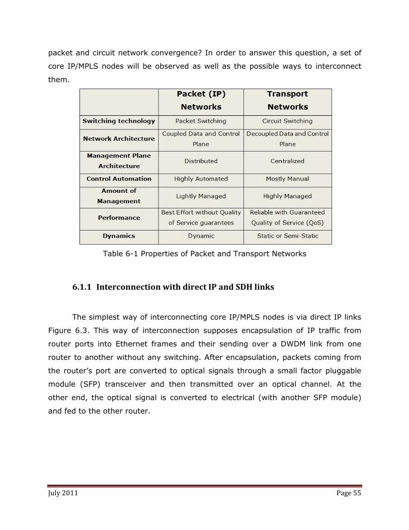
July 2011 Page 55
packet and circuit network convergence? In order to answer this question, a set of
core IP/MPLS nodes will be observed as well as the possible ways to interconnect
them.
Table 6-1 Properties of Packet and Transport Networks
6.1.1 Interconnection with direct IP and SDH links
The simplest way of interconnecting core IP/MPLS nodes is via direct IP links
Figure 6.3. This way of interconnection supposes encapsulation of IP traffic from
router ports into Ethernet frames and their sending over a DWDM link from one
router to another without any switching. After encapsulation, packets coming from
the router’s port are converted to optical signals through a small factor pluggable
module (SFP) transceiver and then transmitted over an optical channel. At the
other end, the optical signal is converted to electrical (with another SFP module)
and fed to the other router.

July 2011 Page 56
Figure 6.3 - Interconnection of 6 core routers into a full mesh topology using 15 direct IP links
The only advantage of this system is simplicity. On the other hand it has
many disadvantages such as:
• Efficiency - IP traffic shows bursty nature even when it is aggregated.
Links between routers must be able to support traffic peeks what
means that they are underutilized most of the time.
• Large number of routing adjacencies - in order to connect N routers in
a full mesh with direct links, each router needs to have N-1 links.
• Restoration and protection – having only links as interconnections
(without any intermediate switching) means that network reliability
can be increased only by over-provisioning. In order to be effective,
this requires a lot of spare resources.
Routers interconnected in this way represent a packet network fully
separated from the transport network. As it is described, the disadvantages of this
architecture highly outweigh its advantages. To cope with this disbalance, SDH
transport network links can be used as interconnections between IP routers, Figure
6.4. Considering that in this architecture IP links are provided by transport network,
it represents a solution that integrates packet and transport networks to some
extent.
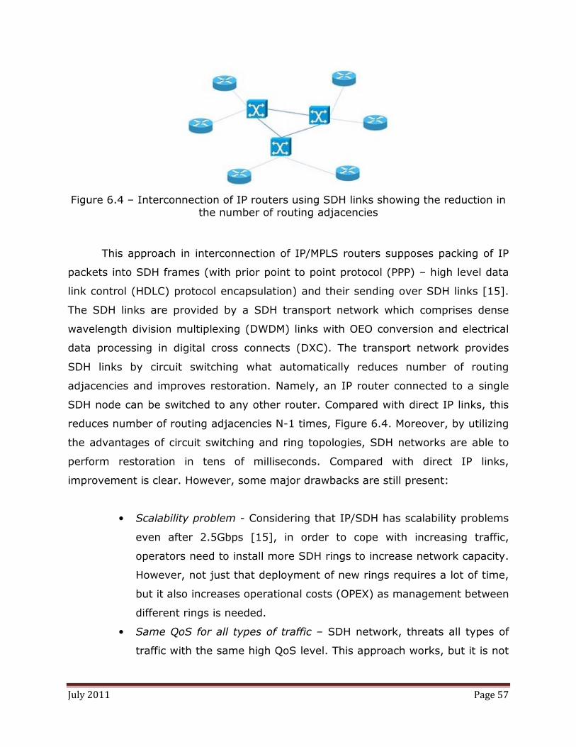
July 2011 Page 57
Figure 6.4 – Interconnection of IP routers using SDH links showing the reduction in the number of routing adjacencies
This approach in interconnection of IP/MPLS routers supposes packing of IP
packets into SDH frames (with prior point to point protocol (PPP) – high level data
link control (HDLC) protocol encapsulation) and their sending over SDH links [15].
The SDH links are provided by a SDH transport network which comprises dense
wavelength division multiplexing (DWDM) links with OEO conversion and electrical
data processing in digital cross connects (DXC). The transport network provides
SDH links by circuit switching what automatically reduces number of routing
adjacencies and improves restoration. Namely, an IP router connected to a single
SDH node can be switched to any other router. Compared with direct IP links, this
reduces number of routing adjacencies N-1 times, Figure 6.4. Moreover, by utilizing
the advantages of circuit switching and ring topologies, SDH networks are able to
perform restoration in tens of milliseconds. Compared with direct IP links,
improvement is clear. However, some major drawbacks are still present:
• Scalability problem - Considering that IP/SDH has scalability problems
even after 2.5Gbps [15], in order to cope with increasing traffic,
operators need to install more SDH rings to increase network capacity.
However, not just that deployment of new rings requires a lot of time,
but it also increases operational costs (OPEX) as management between
different rings is needed.
• Same QoS for all types of traffic – SDH network, threats all types of
traffic with the same high QoS level. This approach works, but it is not

July 2011 Page 58
efficient since some data does not need high QoS level assigned to
them in this way.
• Efficiency – the problem of link utilization neither SDH transport
network can solve efficiently. SDH networks are able to establish links
only semi-statically. This is due to long link provisioning times caused
by both technical (element by element manual configuration of devices
from various vendors that have different management solutions) and
bureaucratic reasons (time spent on communication during circuit
request and price negotiation). Consequently SDH links provisioning
can last even several days, which is way too slow to handle millisecond
bursts in IP traffic.
Generally, although they offer improvements in restoration and number of
routing adjacencies, SDH links struggle with a very important issue, efficient link
utilization. However, this is not the only stepping stone towards their
implementation. Management of a SDH transport network is vastly different than
management of IP/MPLS routers that should reside on top of it. This means that the
two networks have to be managed separately, with different protocols what
increases operational expenses (OPEX). Depending on network topology and its size
it is not always clear whether advantages of SDH network introduction are worth of
additional expenses it produces (both CAPEX and OPEX). Consequently, direct IP
links are still present in some networks as interconnections between IP routers.
6.1.2 Interconnection with OpenFlow-enabled Optical network links
Direct IP and SDH links are not complete solutions for interconnection of
IP/MPLS core devices since they both have many important drawbacks. However,
from the discussion about their pros and cons it is possible to derive requirements
for a cost-efficient transport network used below the IP/MPLS layer. These
requirements are:

July 2011 Page 59
• Scalability in order to follow constant increase of IP traffic
• Fast circuit provisioning in order to deal with link utilization and
restoration
• A control plane that can be used for both IP/MPLS and transport
network
A transport network that satisfies these requirements would be a good match
to IP/MPLS network residing on top of it. It would lead to the unification of two
networks that would result in numerous improvements both to operators and
customers. Customers would benefit from faster service provisioning and higher
quality of service, while operators would have more flexible, efficient and reliable
network together with significant decrease in expenses due to two reasons. Firstly,
better link utilization would result in decrease of their number as well as the
amount of network equipment (fibre, interfaces, SFP modules…). Secondly, unified
control would eliminate one management tool from the network and produce
significant reduction in expenses. Comparing all mentioned advantages (coming
straight from the convergence of two networks) with the drawbacks of the “direct
IP links” architecture (representing total separation between packet and circuit
networks) it is clear why the convergence is highly desirable. Consequently, now
when the reasons for convergence of transport and packet network are clear as well
as the requirements for it, the transport network able to achieve convergence will
be described.
It has been recognized within the IT community that only optical networks
will be able to deal with constant increase of IP traffic [16]. Optical link and
switching capacities are widely recognized as the only possible solution for the
scalability requirement specified above. Consequently, optical transport networks
(OTN) are generally accepted as the transport networks that should reside below
IP/MPLS devices. However, the selection of OTN as transport network does not
facilitate significantly dealing with other two requirements for packet and circuit
network convergence.
In the last decade the most known solution that aimed to fulfil the two
requirements has been Generalized Multi Protocol Label Switching (GMPLS) [16]. It
is a set of protocols aimed to provide unified control of packet and circuit networks

July 2011 Page 60
and through it dynamic and fast circuit establishing and restoration. However,
although being present for more than a decade it has not seen significant practical
deployment yet. Furthermore, today it is considered more as a control plane for
transport networks than a control plane unification tool [17].
On the other side, OpenFlow as a novel approach and paradigm shows a lot
of promises when it comes to the fulfilling of requirements needed for unification of
packet and circuit networks. Namely, in packet networks Open Flow brings
architectural changes. It decouples control plane from the data plane in order to
introduce controlling flexibility. Furthermore, although it defines per packet
processing it performs per flow control. Consequently, what controller sees are not
packets but flows. In addition to this, OpenFlow abstracts packet switches with flow
tables and manages them by modifying their entries. Similarly, in circuit networks
Open Flow abstracts circuit switches with flow tables. A controller sees circuit flows
(cross-connections) and manage them by adding/removing entries in the flow
tables. Consequently, if we define Open Flow packet and circuit networks as
networks consisting of Open Flow enabled packet and circuit switches and put their
properties next to each other in a table, we will see some important similarities
between the two (Table 6-2).
Table 6-2 Properties of Open Flow Packet and Transport Networks
Compared with the Table 6-1, which represents characteristics of non-
OpenFlow packet and transport networks, Table 6-2 shows several important
changes. The first notable change is the switching granularity. While non Open Flow
packet and circuit networks have dealt with packets and circuits, Open Flow
equivalents of these networks both work with flows. The second big change is in the
network architecture where Open Flow creates a full match between packet and

July 2011 Page 61
transport networks. These two similarities, together with the common flow table
switch abstraction provide a base for unified control of packet and circuit networks.
Namely, in a network with both packet and circuit OpenFlow switches a
controller sees only OpenFlow tables. Independently of switch type, features,
technology and vendor the switch is represented by an OpenFlow table. It is true,
that packet and circuit switch tables are different and usually kept separate [14].
However, this does not make any problems to the controller since both of them are
comprised of flow entries and both are managed in the same way, using the same
messages and actions. The same thing stands for the difference between packet
and circuit flows. They are represented by different structures and have different
granularities but since they are controlled in a same way, these differences do not
cause any difficulties. On the other side, comparison of Table 6-1 and Table 6-2
shows clear difference in number of entries. However, control and management
related characteristics have been deliberately left out from the Table 6-2 since Open
Flow does not suppose any specific control on top of it. Choosing between
distributed and centralized, manual and automated control and so on is left to the
network administrator/researcher in order to adapt the control to the network’s
needs.
Eventually, Open Flow protocol offers unified control of heterogeneous
networks that comprise both packet and circuit switches, independently of the
equipment vendor. At the same time it provides wide flexibility in choosing the
most suitable control mechanism. In this way, a transport network consisting of
OpenFlow enabled optical switches shows ability to fulfil scalability and unified
control plane requirements of the transport network specified at the beginning of
this section (6.1.2). With these two problems solved, the only requirement left is
fast circuit provisioning. To which extend optical OpenFlow transport network can
satisfy the last requirement, will be described in the next section. It will be done by
observing the transport network performance in its complete working environment,
a unified packet and circuit OpenFlow network.

July 2011 Page 62
6.1.3 Abilities of Unified packet and circuit OpenFlow-enabled network
Generally, a network comprising both OpenFlow-enabled packet and circuit
switches (unified OpenFlow network) is supposed to have a topology like the one
shown in Figure 6.5. In this topology OpenFlow packet switches form two or more
administrative domains, called OpenFlow islands, while OpenFlow circuit switches
are used to provide interconnections between the islands. These interconnections
are supposed to be established between edge nodes in each island. The edge nodes
are hybrid nodes that have both packet and circuit interfaces. Packet interfaces of
each hybrid node are connected with packet switches from the island it belongs to,
while their circuit interfaces are connected to the other hybrid nodes.
Figure 6.5 - Unified Packet and Circuit OpenFlow Network [17]
Nevertheless, discussing performance and abilities of the unified OpenFlow
network is inextricably bounded to the control implemented on top of it. This
immediately invokes the question of choosing between distributed and centralized
controller. Since the OpenFlow circuit switches present an immature technology and
cannot be found in the market, unified packet and circuit OpenFlow networks are to
a great extent an unexplored topic. Consequently, as a simpler approach
centralized control of all devices sounds like a better starting solution.

July 2011 Page 63
Using of centralized control on top of the described topology simplifies things
a lot. Considering packet islands, their controlling does not differ at all from the
control described in Chapter 3.1. The only novelty is that the packets can be
forwarded to another island. When such a request arrives to the controller, i.e.
when controller calculates that the packet should be forwarded to an address
belonging to different island, it has to provide forwarding path over the circuit
switches. To achieve this it requires: circuit network topology, routing algorithm
and a way to signalize calculated route.
Circuit network topology in centralized controlling environment is mostly
predefined. Preconfigured permanent or static links as well as all available (but not
configured at the start up) links are provided to the controller prior to its running.
Considering the topology, the controller’s job is only to update information about
occupied and available links as new connections are established. Same stands for
the available wavelengths in the network. The available topology information is
used by a routing algorithm to calculate the path across the transport network.
However, since its function is independent of the physical layer and OpenFlow, this
topic will not be discussed in more details. Nevertheless, once when the path is
calculated it has to be signalled, i.e. the switches on the path need to be
configured. Signalling in the described environment is completely done by using
OpenFlow messages. Configuring of circuit switches is nothing else but establishing
of bidirectional cross-connections between its input and output port. As described in
Chapter 6, this is done by sending a simple OpenFlow message which installs the
corresponding flow entry in the flow table of the switch.
Taking all three steps into account, it is obvious that dynamic establishing of
circuits across the transport network is possible in Unified OpenFlow networks. This
feature combined with other OpenFlow characteristics introduces the following
possibilities:
• Creation of dynamic packet links – being provided over dynamic circuit
links, packet links between routers can be provided at the similar
speed as circuit links, i.e. with a negligible delay. Moreover as a result
of centralized control decisions, new links do not have to be

July 2011 Page 64
disseminated across the network. Consequently, there are no
convergence times which are encountered in distributed systems. In
other words, having link establishing which is non-disruptive to other
flows decreases the link set up time and improves the dynamics of link
set up/tear down procedure.
• Dynamic Service-aware Aggregation and Mapping – Flexible flow
aggregation is an inherit feature of OpenFlow packet switches. By
specifying flows with the corresponding TCP/IP parameters it is very
easy: to aggregate traffic coming from a certain user(s), to divide
voice, data and video traffic or just put whole traffic together. For
example: specifying a flow with TCP port 80 will aggregate web traffic
from all users. In similar manner, voice and video traffic can be
aggregated by specifying flows with TCP port 5060 and UDP port 1234
respectively. Moreover, the described traffic aggregation is helpful not
just for its easier handling but also to facilitate the problem of huge
number of entries in core routers. However, the significance of flexible
traffic handling gains on importance even more when it is known that
OpenFlow devices can support different controlling mechanisms.
• Application-Aware Routing – Using the benefits of first two features
together with OpenFlow support of various controllers it is possible to
create paths that are tailored to specific applications. While the second
feature allows aggregation of application specific traffic (e.g. voice,
data, video traffic), the dynamic packet link feature allows path
creation according to different controlling mechanisms, totally adjusted
to accommodate needs of application specific traffic we want to
transmit. For example, for latency sensitive voice traffic there can be
dynamically created a circuit over shortest possible path in order to
minimize packet latency. For latency jitter sensitive video traffic a non
shortest optical path can be created keeping the traffic in optical
domain. Avoiding of routers and electrical processing in this case is
important due to the constant latency requirement.

July 2011 Page 65
• Variable Bandwidth Packet Links - By monitoring bandwidth usage of
the circuits that are used to build a packet link, new circuits can be
dynamically added when they are needed. In this way congestion
could be avoided leading to higher utilization of available links. For
example, video traffic is much more “traffic hungry” than voice or http
traffic and hence can much easier lead to link congestion. This can be
monitored by checking how much buffer at the transmitting side is
filled with packets. When certain threshold value is passed, procedure
for establishing of a new link may be triggered.
• Unified Recovery – With all routing information and decision making
centralized it is possible to perform network recovery from failures
according to specific needs of some services. For example, voice traffic
can be dynamically re-routed (since it is relatively small and sensitive
to latency, it should be quickly re-routed); video can be protected with
pre-provisioned bandwidth while http can be re-routed over packet
topology.
As it can be seen, the enlisted features and abilities of unified OpenFlow
networks include dynamic packet link establishing and its usage for restoration and
dealing with the link efficiency. However, it is very important to distinguish between
ability to provide dynamic links and the speed at which they are provided. Bursts in
aggregated traffic are characterized with durations in millisecond region while
proper restoration should be done within 50 ms time interval. Consequently, it is
not enough to provide packet links dynamically. They have to be provided in tens of
milliseconds times.
Unfortunately, these set up times still cannot be achieved [18]. However
there should be taken into account that only couple of demo experiments with
Unified OpenFlow networks have been done so far [17], [18]. Their aim has been to
experimentally prove that above-described features are possible and this aim has
been successfully fulfilled. On the other hand, improving of link set up times
requires a dedicated research and can be an interesting topic for a further research.
Eventually, Unified OpenFlow Networks at the moment cannot satisfy all the
requirements that have been placed upon them. The main problem of these

July 2011 Page 66
networks so far has been speed at which circuits are established and tore down.
However, its immatureness, list of improvements that were achieved in just couple
of years as well as its possibility to support various control mechanisms and ideas
make it a good prospect for the future considering unification of packet and circuit
networks.
6.2 Alternative OpenFlow Solutions
Unlike OpenFlow Packet switches that are currently produced by top network
equipment vendors such as NEC, IBM, Juniper and Hewlett-Packard, OpenFlow
Circuit switches are not available on the market. There are several reasons for this:
• OpenFlow has been originally designed for packet switches. Only recently
its extension to circuit switches have been considered. Consequently,
developing of OpenFlow specification for circuit switches lags a lot behind
specification for packet switches. Namely, while circuit switch specification
is in draft phase [14], specification for packet switches has experienced its
second implemented version [10]. Without clear specifications, there is not
anything to be implemented.
• Optical circuit switches required in Unified OpenFlow Networks are still
immature devices with many unsolved and pressing issues. Consequently,
vendors are more focused on solving of these issues than on enabling
programmability of their devices. Prior to providing optical circuit switching
technology with some additional functionality (such as OpenFlow), the
technology should be first well established both in the market and in the
field. Considering that there are no pressing urges for development of
OpenFlow enabled circuit switches, vendors are still reluctant to enable
their devices with OpenFlow functionality.
Having this in mind and not being eager to wait for circuit switches vendors’
approval of OpenFlow, research community is trying to work with existing non-

July 2011 Page 67
OpenFlow circuit switches and use them to connect OpenFlow islands. One such
solution will be presented in the next section.
6.2.1. GMPLS-OpenFlow Interoperability
Discussion about integration of OpenFlow and GMPLS requires a short
introduction about the latter. More details about it can be found in [16] and
especially in [19], a book written by one of the fathers of GMPLS, Adrian Farrel.
GMPLS has originated as an extension of MPLS which in turn has been
designed as an extension of IP routing aimed to provide virtual circuit switching at
the IP layer. MPLS provides its goal using the concept of constraint based routing.
In this concept, extended IP link-state routing protocols like Open Shortest Path
First (OSPF) or Intermediate System to Intermediate System (IS-IS) are used to
gather topology information. Their extension is needed in order to include available
link bandwidth as a parameter in routing process. Topology information gathered by
these protocols is used by Constraint Shortest Path First (CSPF) heuristic to
calculate forwarding paths across the network. Calculated paths are established
using the Resource Reservation Protocol (RSVP) protocol that configures the nodes
along them. One by one, all nodes on the desired path are checked if they can
reserve enough bandwidth as it is required. The last checked node sets the label for
the required destination and informs the previous node. The label assignment
process goes backwards. Once when labels are assigned, incoming packets that
arrive to a MPLS domain are checked against routing table. When a match is found,
the label from the matching entry is added to the packet and it is forwarded to the
next hop. From that point on, packet is forwarded only according to its label,
without looking into its content.
The described concept of path establishing, known as virtual circuit
establishing, is quite similar to the circuit establishing of optical networks.
Consequently, protocols utilized in MPLS have been extended under generalized
MPLS umbrella, in order to be used in optical circuit switching networks. That
resulted in a protocol set, known as GMPLS, which is able to control optical
networks in distributed and automated fashion. Without going into details of all

July 2011 Page 68
protocols included into GMPLS suite, it is clear that GMPLS is a full controlling
solution.
The fact that GMPLS specifies how control should be done, distinguishes itself
very much from OpenFlow which leaves the control choice and design to
researchers or administrators. Considering that the two have different aims it may
sound wise to question the rightness of GMPLS incorporation under OpenFlow
umbrella. However, in the absence of OpenFlow enabled optical switches it does
make sense to try to use GMPLS controlled transport networks for lightpath
provisioning between different OpenFlow packet domains. Furthermore, considering
that GMPLS has been being developed for more than a decade, there are a lot of
GMPLS test-beds at many research institutions around the world. Inclusion of this
infrastructure to the global OpenFlow network would increase its capability
significantly. At the end, if in some near future OpenFlow reaches global popularity
and becomes widely accepted networking standard, by that time GMPLS can have
some share of the circuit switching market and it would have to be included as a
legacy technology. With these reasons in mind, there will be described an
architecture for integration of OpenFlow packet islands and GMPLS transport
network(s).
In order to describe requirements for GMPLS integration with OpenFlow,
there will be considered a topology that comprises two OpenFlow packet islands
(domains) physically interconnected by GMPLS transport network links, Figure 6.6.
The proposed architecture, assumes that all packet domains are controlled by
a single NOX controller, which is responsible for topology discovery and packet
forwarding inside the domains. The GMPLS transport network is controlled by
GMPLS controllers independently of the NOX controlling mechanisms and routines.
This means that the two networks are interconnected in an overlay model where
the upper layer packet network, acting like a client, requests service from the lower
layer GMPLS transport network, that acts like a service provider. The two do not
have any visibility inside each other and the whole communication between them
occurs via user-to-network (UNI) interface. Over it, NOX controller requests a
GMPLS path, whose data GMPLS transport plane provides in the response.

July 2011 Page 69
Figure 6.6 - GMPLS network integrated with OpenFlow network in overlay model
To support this topology, it is necessary to convert electrical signals from the
packet switching domain to optical signals that are transmitted over the GMPLS
network. This has to be done at the border of packet domains for every out-band
connection towards other domains. The easiest way to achieve this is to use hybrid
nodes that have both packet and circuit (optical) interfaces. Their packet interfaces
can be connected to other switches from the domain while the optical interfaces can
serve as connections to the ROADMs in the GMPLS network. Nevertheless, due to
the fact that optical links usually carry more than one wavelength, optical interfaces
are specified not just by port number but also by supported wavelengths on each
port. This means that NOX controller cannot perform flow establishing by specifying
only output port. To establish a flow both output port and selected wavelength on it
need to be specified. Consequently, NOX has to be aware of ports with circuit
interfaces what requires some changes in original OpenFlow specifications. More
importantly, usage of the hybrid nodes beneath the NOX controller requires that
they are OpenFlow enabled. Considering that OpenFlow enabled hybrid switches are
not commercially available, their usage in integration of GMPLS and OpenFlow is
not viable so far.
Another solution for matching the gap between optical and electrical devices
is to use optical transceivers after packet interfaces of the edge switch. To support
more than one wavelength per GMPLS link, the transceivers need to be tunable.
However, since tunable transceivers are still immature and very expensive, the only
solution is to use fixed-wavelength transceivers. Usage of transceivers at different

July 2011 Page 70
but fixed wavelengths causes underutilization of GMPLS devices because in that
environment they can work with only one wavelength per port. Nevertheless, since
fixed transceivers are the only possible solution, they will be considered in the rest
of the chapter.
The existence of optical links after packet switching ports suggests that these
ports cannot be treated like other packet switching ports. This fact yields several
changes in the way NOX controller should treat edge nodes compared to legacy
OpenFlow switches. Identifiers (numbers) of the ports that have transceivers should
be provided to the controller prior to its starting. These ports should be observed as
optical and kept separately from the electrical ports. Since NOX controller is
implemented in Python programming language, the list of all “optical” ports can be
stored as a nested dictionary. An example is given below:
edge_switch_1 = {op1: [GMPLS_port1, lambda1], op2: [GMPLS_port2,
lambda2], op3 : [GMPLS_port3, lambda3] …}
edge_switch_2 = {op1: [GMPLS_port1, lambda1], op2: [GMPLS_port2,
lambda2], op3 : [GMPLS_port3, lambda3] …}
….
optical_port_list = {dpID_1: edge_switch_1, dpID_2:edge_switch_2,…}
Dictionary optical_port_list contains descriptions of all optical ports from all
domains. For the specified datapath ID of an edge switch, it returns another
dictionary (edge_switch_X) which associates “optical” port identifiers (opX) with the
list containing the corresponding GMPLS port and the wavelength used on the link.
The separation of packet and “optical” ports can be justified by the fact that the two
kinds of ports are used for different purposes. Namely, while packet ports are used
for intra-domain forwarding, circuit ports are used solely for inter-domain exchange
of information. Moreover, separation of ports according to their types prevents
iterative sending of LLDP packets through the optical ports, restraining Discovery
application function to the packet ports for which it has been designed. This
restraint is needed due to two reasons. Firstly, sending of several light-weight
packets over the optical ports in every second leads to severe underutilization of

July 2011 Page 71
GMPLS resources. Secondly, since these packets cannot be forwarded back to the
NOX controller, link state cannot be inferred from them. Consequently, their
sending over optical port is totally useless and must be prevented either by
separation of packet switching and optical ports or in some other way. Since the
separation can be provided quite simply, in this work, it has been proposed as a
solution for this problem.
In the described environment, packet forwarding goes as it is depicted in
Figure 6.7. When a packet is forwarded to the controller for the first time, there
should be decided to which domain it is supposed to be forwarded. Performing of
this task is highly dependent on an addressing scheme used inside domains. Since
this is left to the administrator/researcher that writes the controlling application, it
is impossible to provide general solution for distinguishing between domains.
However, if OpenFlow packet domains are realized as IP networks, with all devices
in the domain having the same network ID, the task can be done easily. With the
use of IP source and destination addresses and the subnet mask information, it can
be checked whether the network part of IP destination address matches the IP
address of the domain in which it has originated. If the match exists, NOX controller
can easily forward it according to the specified routing utilizing only packet
switching ports (i.e. there is no need for involvement of optical ports and GMPLS
service). In case that the match does not exist, packet should be forwarded using
the service of GMPLS transport network. Nevertheless, in order to be able to extract
IP address information from the packet, the whole packet has to be forwarded to
the controller. By default, OpenFlow is configured such to forward only the header
of a transmitted Ethernet packet (first 128Bytes), while the original packet is
buffered at the switch. In this way, the amount of traffic exchanged between
controller and switches is minimized, leading to faster performance. However, this
forwarding can be configured by controller designer. Since the IP header, containing
source and address destinations, is contained in the payload of the Ethernet packet,
the whole packet has to be forwarded to the controller. This can be achieved by
changing NOX file openflow.h in order to specify maximal number of bytes that are
forwarded to the controller as 1538.

July 2011 Page 72
Figure 6.7 - Flowchart describing messages exchange during packet forwarding to
another domain
With the whole packet at its disposal, the controller has all information it
needs to decide to which domain the packet should go. When it decides to forward
the packet to a domain different then the source domain, it requests service from
the GMPLS transport network. For this, it should send a message that contains IP
address of the destination node and the IP address of the interface through which
source packet domain is connected to the GMPLS network. Since format of this
message depends on GMPLS controller realization and is not restrained by
OpenFlow protocol in any way, its implementation goes out of the scope of this
work and will not be discussed in any more details.
After the reception of this message, based on the requested destination
address GMPLS performs routing, path selection and node configuration. Upon path
establishing, GMPLS controller should communicate necessary details of the
established path to the controller. Generally, these details should include: path ID,
ingress switch port and wavelength as well as egress switch port and associated
wavelength. Since in our case, wavelength and ports on “optical” links are mapped
in 1:1 relation, it is enough to specify only the ports. Ingress and egress switch
ports sent by GMPLS control plane to the NOX controller are real optical ports of
ROAMDs. Since NOX controller does not see these devices and their ports, by using
the mapping between packet port (opX in edge_switch dictionary) and optical port
(GMPLS_portX in edge_switch dictionary), the NOX controller is able to identify the
packet port over which it is supposed to connect to the specified GMPLS port. That

July 2011 Page 73
information (port ID) NOX controller puts in the ofp_flow_mod OpenFlow message
used for establishing of new flows.
struct ofp_flow_mod {
struct ofp_header header; struct ofp_match match; /* Fields to match */
uint64_t cookie; /* Opaque controller-issued identifier. */
/* Flow actions. */ uint16_t command; /* Bitmap specifying what is to be
done with the flow: addition, deletion, modification */
uint16_t idle_timeout; /* Idle time before flow expires
(seconds) */ uint16_t hard_timeout; /* Max time before flow expires
(seconds) */ uint16_t priority; /* Priority level of flow entry. */ uint32_t buffer_id; /* Buffered packet to apply to (or -
1).*/ uint16_t out_port; /* Port to which packet will be
forwarded */ uint16_t flags; /* Flags for management issues*/ struct ofp_action_header actions[0]; /* Action header specifying the action
type*/ };
With the command bitmap set to ADD option (0x01 value) and out_port set
to port number of packet port leading to the GMPLS port (e.g. op1) this message,
installs the new flow and sets up the connection to the established path in the
GMPLS network. The other parameters like idle timeout, hard timeout, priority or
flags can be chosen according to administrator preferences. The same procedure is
performed at the destination domain, where the corresponding edge node is
configured in the same manner in order to connect established GMPLS path to the
destination domain.
In this way it is possible to integrate GMPLS networks with OpenFlow without
any changes in OpenFlow and with only minimal modifications of the controller.
Their interconnection using overlay model, means that fundamental problems in
each layer will stay intact, but all the motives laid down in Chapter 6.2.2 will be
fulfilled.

July 2011 Page 74

July 2011 Page 75
7. Virtualization of OpenFlow Circuit Switching Networks
When it has been introduced in Chapter 6, extension of OpenFlow from
packet to circuit switches has been justified by its ability to provide packet and
circuit network convergence. However, considering that controller sees OpenFlow
circuit switches as flow tables and manages them in the same manner like packet
switches, it sounds reasonable to check whether FlowVisor can be used to virtualize
circuit networks in the similar way like packet networks. Nevertheless, prior to
investigating FlowVisor’s abilities in OpenFlow circuit switching networks, it will be
explained shortly where virtualization of optical networks can be applied and why it
has not been achieved so far.
Within this work, network virtualization has been introduced and mainly
considered as an enabling tool for testing of new research ideas. For this purpose,
virtualization of packet networks on university campuses has been described.
Virtualization of optical circuit networks owned by big telecommunications
companies could also go under “enable innovation” umbrella, but telco operators
have traditionally sought for more convincing reasons before allowing architectural
changes in their networks. Their main “more convincing” reason has usually been
an increase in their profit. Operators are not willing to jeopardize their current profit
by installing new equipment, just to enable more research possibilities. In order to
agree to virtualize their networks, they need to gain something more from it.
First thing that operators can gain from network virtualization is reduction of
expenses. With network virtualization they can run different service networks as
virtual networks on top of same physical infrastructure. This could allow merging of
existing voice, video and data networks onto same physical network. Moreover, it
would make provisioning of future services much faster and cheaper. Instead of
developing a new separate physical network, a new service could be provided on a
virtual network.
Besides using the infrastructure for providing its own services, with network
virtualization operators can provide virtual networks to other customers in what is
known as Infrastructure as a Service (IaaS). In this manner operators could provide

July 2011 Page 76
network resources (topology, bandwidth, links and QoS…) requested by another
service provider in terms of a virtual network, allowing both arbitrary and specific
control on top of it. An example of such interaction can be virtual optical networks
used for grid computing networks. Namely, data gathered in big experimental
facilities like Large Hadron Collider (LHC) are usually distributed and computed on
different geographical locations. Scheduling of data computation is done by Joint
Task Scheduler whose proper working requires flexible and reconfigurable networks
with huge bandwidth links. Perfect match for this can be virtual optical networks
leased from telecommunication companies [20].
With these few short case-studies showing how telecommunication
companies can benefit from virtualization of their optical infrastructure, it is clear
that virtual optical networks are highly desirable. Their advantages have been
recognized for some years by research community but not a single architecture
proposal has been realized. The main reason for this has been the analogue nature
of physical layer resources and transmission formats. Successful solutions for layer
2 (L2) and layer 3 (L3) networks, such as VLANs and VPNs, are mainly based on
discrete nature of L2 and L3 network resources and transport formats. These
advantages do not exist in optical layer 1 networks which deal with wavelengths, so
some new approaches have to be tried. Consequently, with the serious lack of layer
1 virtualization solutions it is worth checking out whether FlowVisor on top of
OpenFlow enabled switches can provide desired virtual optical networks.
7.1 Optical Network Virtualization with FlowVisor
FlowVisor has been designed as a virtualization layer for packet switches.
However, it works with flow tables that represent packet switches. Consequently, it
sounds reasonable to check whether virtualization of 5 networks resources (traffic,
topology, bandwidth, switch CPU time and flow table) achieved in packet networks,
can also work for Open Flow tables that abstract circuit switches. Nevertheless,
although OpenFlow circuit switches encompass both optical (OXCs and ROADMs)
and SDH switches, our attention will be focused on virtualization of optical switches.
Reason for this is the fact that optical switches are seen as main and most

July 2011 Page 77
important devices of future circuit networks. Hence, from now on, term optical
network will be used to refer to a network comprising of OpenFlow enabled OXCs or
ROADMs.
Considering topology virtualization in optical networks, approach is the same
as in packet networks. The problem is again divided into two: virtual node
discovery and link discovery. By proxying connections between switches and
controllers, FlowVisor is able block or allow connection of a physical node to a
particular controller. By blocking connection requests from the switches that are left
out from the virtual topology and allowing others, FlowVisor is able to meet
demands for arbitrary virtual topologies based on the real one. When considering
link discovery between virtual circuit switches, there is no need for Discovery
application used in packet networks. As it has been mentioned before, optical
network topology is built using the static links that are provided at the start up. As
new links are established or torn down the topology is dynamically updated by the
controller. During this process FlowVisor does not have any special role.
Consequently, this means that it can provide virtual topology virtualizing the first
resource of optical networks.
Same like topology, flow table virtualization in optical networks can be also
done reusing the mechanism defined for packet networks. Being made of entries,
flow table of an optical node can be virtualized by assigning disjoint subsets of
entries to different virtual networks (slices), Figure 7.1. However, the big difference
between circuit (optical node) and packet flow table entries is the granularity of the
flows their represent. Namely, circuit flow entries are bidirectional entries that
represent cross-connections between input and output interfaces of the switch.
These interfaces are specified as [port, wavelength] pairs, so optical circuit flow is
nothing else but a wavelength between two ports. The stated fact has two
important implications. Firstly, in today’s systems a single wavelength can carry 10,
40 or even 100Gbps what means that every optical flow entry represents much
more traffic than its packet network peer. Secondly, by assigning a flow entry to a
slice we are assigning a wavelength together with its associated spectrum.
Consequently, by virtualizing flow table we implicitly virtualize available bandwidth,
where available bandwidth is defined by total number of ports and wavelengths per

July 2011 Page 78
port supported in the optical circuit switch. Moreover, since resource allocation is
dedicated (i.e. only one slice can use the assigned wavelength) and every
wavelength works at exactly specified bit rate, every flow table entry has some QoS
level guaranteed.
Figure 7.1 - Flow Table Virtualization in OpenFlow Circuit Switches
Switch CPU time virtualization is also much easier to handle in optical than
in packet switches. As it has been stated in section 4.2, in packet switches there
are two possible data sources that can lead to CPU overload: packet-in messages,
and controller requests. In circuit switches there is no checking of incoming data
against the flow table entries. In addition to this, there are no packet-in messages
so the first cause of CPU overload in circuit switches does not play any role CPU
time virtualization. Unlike packet-in messages, controller requests exist also in
optical switches. However, since there are no counters used for per packet and per
flow statistics, rate of port status and other similar requests can be higher than in
packet networks. Nevertheless, since controller does not have any limitation when
generation of these requests is considered, it is capable of overloading the CPU.
However, FlowVisor can prevent this easily by specifying maximal rate of controller
requests for each slice. In addition to all this, circuit flows are established, torn

July 2011 Page 79
down, modified at much slower rate than packet flows so theoretically there should
not be many problems with switch CPU overloading in OpenFlow circuit networks.
Traffic virtualization in packet networks, as specified by FlowVisor, is done by
defining slice policies which contain description of traffic every slice is allowed to
control. Since in circuit switches there is no traffic inspection, this approach cannot
be utilized. Moreover, without any insight into traffic carried by each wavelength,
the only traffic virtualization possible in circuit switches is assigning of traffic
portions carried by each wavelength to a specific slice. Since this is done by flow
table virtualization, it is clear that in optical switches: bandwidth virtualization,
traffic virtualization and flow table virtualization are done in a single step.
Considering that topology and switch CPU time virtualization are done without
many problems, conclusion is that FlowVisor can be used to virtualize OpenFlow
enabled circuit switches. However, it is questionable how efficient this virtualization
is.
Assigning of 100Gbps traffic portions to virtual optical networks can lead to
the problems with efficient link utilization. Moreover, independently of traffic
engineering algorithm used for putting packet flows into circuit flows, absence of
finer granularities creates a lot of problems when it comes to flexible forwarding of
traffic. In addition to this, the number of different wavelengths supported by
today’s switches is pretty low. Consequently, total available wavelength pool is
quite scarce what severely limits the number of virtual optical networks that can be
created on top of available physical architecture.
As it can been seen, optical network virtualization with FlowVisor running on
top of OpenFlow enabled circuit switches has quite limited performance. However,
all these limitations are not products of OpenFlow or FlowVisor’s characteristics.
They result from the architectural characteristics of today’s optical switches. Their
inability to provide granularities finer than a wavelength granularity makes optical
network virtualization inefficient. A solution for these problems can be Optical
Orthogonal Frequency Division Multiplexing (OOFDM) which aims to provide sub-
wavelength granularities by using overlapped orthogonal carriers running at lower
speeds [21]. Since they are modulated and transmitted independently of each other
they can be flexibly combined into optical links of different granularities ranging

July 2011 Page 80
from sub-wavelength to wavelength-band bandwidths. Nevertheless, this
technology is highly immature and currently considers only single link transmission
systems. Optical switches with sub-wavelength granularities, which are needed in
order to speak about networks and network virtualizations, to the best of our
knowledge, have not seen any serious architecture proposals.
Eventually, FlowVisor and OpenFlow theoretically could virtualize optical
switches available today, extracting out of them the performance they offer. For the
fact that the extracted performance probably could not satisfy the needs of virtual
optical networks, the two are not to be blamed for. As stated in the introductory
part of this work, aim of virtualization is to create virtual devices and networks
which will mimic the behaviour and performance of their physical representatives.
Virtualization cannot go beyond performances of real devices creating something
that does not exist in physical equipment.

July 2011 Page 81
8. Experimental Part
In the previous seven chapters many concepts have been described and laid
down, both for packet and circuit OpenFlow networks. This chapter describes
results obtained during a familiarization with the architecture of a real system
comprising OpenFlow-enabled packet switches, FlowVisor and NOX controllers.
The equipment used for this purpose, both hardware and software, has been
provided by Catalan research foundation i2Cat who were kind enough to let us
experiment on their OpenFlow network. Providing of results that will be described in
this chapter would be much harder without their help. Namely, today there are only
a dozen of OpenFlow networks in the world. They are spread all over the world and
act as independent OpenFlow islands. In such environment, “hands on” experience
with OpenFlow switches represents a real privilege.
8.1 Testing Environment
The i2Cat's OpenFlow island, that has been used to conduct experiments
described later in this work, comprises:
• 5 NEC IP8800/S3640-24T2XW switches – The switches are Open Flow
enabled running OpenFlow protocol version 1.0. Physically they have 24 x
1Gigabit Ethernet ports and 2 x 10 Gigabit Ethernet ports. 16 ports are
OpenFlow enabled while the others work as “normal” Ethernet ports.
• 4 XEN virtualized SuperMicro SYS-6016T-T servers. Two of them have 2 x
Intel DP Nehalem E5506 2,13GHz,12GB DDR3 RAM 2x 1TB HD RAID1, 6 x
1GB Ethernet interfaces while the other two have 2 x Intel DP WestMere
E5620 2,4GHz,12GB DDR3 RAM ,2x 1TB HD RAID1, 6 x 1GB Ethernet
interfaces.

July 2011
The switches are interconnected in a full mesh topology as it is shown in the
Figure 8.1. On the figure they are represented by their extended MAC addresses
(00:10:00:00:00:00:00:01 to 00:10:00:00:00:00:00:05), which are in OpenFl
terminology known as 64-bits
IDs differ only by their last number, from now on, the switches will be referred to as
Switch 1 – Switch 5. The switches are interconnected such that Switch 1 is
connected to port 1 of other 4 switches, Switch 2 to port 2 and so on.
Figure 8.1 - Topology of the OpenFlow island used for experimentation
The virtualized servers host Virtual Machines (VM
control the network consisting of five OpenFlow switches. Unlike switches, the
servers are known by their string names: March, Rodoreda, Llull and Foix. Three of
them (March, Rodoreda and Foix) are shown in the
omitted since in our experimentation it has been used only for accessing the control
framework. As it can be seen from the
connected to all switches. Although in ideal configuration every server should be
connected to all switches, in practice it requires a lot of interfaces on both
connection which automatically increases the equipment cost significantly.
Consequently, each server is connected to only 1 or 2 switches. The
interconnections are presented in the
The switches are interconnected in a full mesh topology as it is shown in the
. On the figure they are represented by their extended MAC addresses
(00:10:00:00:00:00:00:01 to 00:10:00:00:00:00:00:05), which are in OpenFl
bits datapath ID-s. However, considering that datapath
s differ only by their last number, from now on, the switches will be referred to as
The switches are interconnected such that Switch 1 is
port 1 of other 4 switches, Switch 2 to port 2 and so on.
Topology of the OpenFlow island used for experimentation
The virtualized servers host Virtual Machines (VM-s) that are used to run and
control the network consisting of five OpenFlow switches. Unlike switches, the
string names: March, Rodoreda, Llull and Foix. Three of
oreda and Foix) are shown in the Figure 8.1 while Llull has been
experimentation it has been used only for accessing the control
framework. As it can be seen from the Figure 8.1 the three servers are not
connected to all switches. Although in ideal configuration every server should be
connected to all switches, in practice it requires a lot of interfaces on both
connection which automatically increases the equipment cost significantly.
Consequently, each server is connected to only 1 or 2 switches. The
interconnections are presented in the Table 8-1.
Page 82
The switches are interconnected in a full mesh topology as it is shown in the
. On the figure they are represented by their extended MAC addresses
(00:10:00:00:00:00:00:01 to 00:10:00:00:00:00:00:05), which are in OpenFlow
r, considering that datapath
s differ only by their last number, from now on, the switches will be referred to as
The switches are interconnected such that Switch 1 is
port 1 of other 4 switches, Switch 2 to port 2 and so on.
Topology of the OpenFlow island used for experimentation
s) that are used to run and
control the network consisting of five OpenFlow switches. Unlike switches, the
string names: March, Rodoreda, Llull and Foix. Three of
while Llull has been
experimentation it has been used only for accessing the control
the three servers are not
connected to all switches. Although in ideal configuration every server should be
connected to all switches, in practice it requires a lot of interfaces on both sides of
connection which automatically increases the equipment cost significantly.
Consequently, each server is connected to only 1 or 2 switches. The

July 2011 Page 83
Table 8-1 Interconnection between switches and servers in the OpenFlow island
The table shows that, for example, server March is connected to the port 12
of the Switch 4 via its interface 2 and to the port 11 of the Switch 5 via its interface
3. In this way out of 16 available OpenFlow ports at each switch 4 ports are used
for interconnections towards other switches and two/one are used for connections
towards the servers. The remaining 10/11 ports (depending on the switch) are not
used in this configuration.
Considering servers and their connections, besides the two interfaces
connected to OpenFlow ports of two switches, every server has one of its interfaces
connected to a non-OpenFlow port on one of the switches. The purpose of this
connection will be described later in this section as a part of discussion about
controlling network.
The described physical infrastructure, consisting of servers and switches, is
offered to researchers through the controlling framework. The controlling
framework virtualizes the physical infrastructure and offers it to various
researchers. Namely, each switch is connected through the control network to the
FlowVisor. The FlowVisor runs on VM hosted on one of the servers, but its exact
deployment is not visible to researchers. Once when a researcher registers with the
network administrator for the service of controlling framework, it can start creating
its experiment. Inside the framework, researchers are allowed to create projects
and within those projects:

July 2011 Page 84
• to add new members which will contribute their traffic to the experiment
• to create various slices representing different networks
For each of its slices, the researcher is able to choose two types of resources:
• OpenFlow switch resources – that represent OpenFlow switches and
corresponding ports the researcher plans to use. By choosing these
resources, the researcher generates network part of its virtual topology,
i.e. nodes and links.
• Virtualized server resources - that represent VM-s on various servers.
Researcher creates these VMs by himself. They are pre-configured Linux
Debian 6.0 machines which can be used: to run controllers, to act like
traffic generators or sinks or for any other purpose.
After selecting these two types of resources, the next steps towards slice
creation are flowspace selection and controller specification. The flowspace selection
is supposed to be done right after choosing of OpenFlow resources. Its aim is to
allow the researcher to specify the traffic which FlowVisor will assign to the slice
and forward it to the corresponding controller. This traffic is specified as a set of
flowspaces using the tables such as the one depicted in Figure 8.2. Each table
specifies one flowspace where each slice can have an arbitrary number of them. As
it can be seen from the Figure 8.2, within the tables the desired traffic is specified
in terms of 9 fields found in Open Flow header (Figure 2.3). For each of the fields,
values are specified as ranges from value1 to value2.
Consequently, the flowspace defined in the Figure 8.2 specifies all packets
with IP source address between 192.168.10.10 and 192.168.10.20. This means
that any packet with an IP address belonging to the specified range is considered as
traffic belonging to the slice. Accordingly, FlowVisor will forward it only to that
slice's controller, performing traffic virtualization described in the previous chapter.
Considering that there can be an arbitrary number of these tables within a slice, in
order to get total traffic assigned to the slice the tables are XOR-ed.

July 2011 Page 85
Figure 8.2 - A Flowspace example specifying traffic with IP addresses from 192.168.10.10 to 192.168.10.20
After selecting the traffic it wants to control, the researcher makes the
selection official by issuing a request for the selected resources. This request needs
to be approved by network administrator, after which the virtual network is almost
complete. The only thing missing is the network control. To discuss its
implementation in a little bit more details, here we consider the case of a
centralized controller, the only type of control which has been used so far in
OpenFlow networks.
In described environment the controller is supposed to run on a VM created
on a server. As specified by OpenFlow and supported by FlowVisor, it can be any
type of control. Independently of how the controller is implemented, there should
be a connection between it and switches, i.e. all switches should be able to send
packets to the controller and the controller should be able to modify tables of all the
switches. Considering that this exchange must go over FlowVisor, the FlowVisor
should have connections towards all the switches and a connection to the controller.
While the connection towards the controller is not o problem, connecting the
FlowVisor with the switches using direct connections might be a one. Namely, by
using this way of interconnection, N switches require N interfaces on a machine
(server) running FlowVisor. This automatically places high burden on the server
running the FlowVisor and increases expenses. To avoid spending more money
without essential improvement in performance, control channels from the FlowVisor
towards the switches have been realized using a single direct connection from one
of its interfaces to a non-OpenFlow port (“production” port) of a switch and

July 2011 Page 86
controlling network. The controlling network is a LAN network consisting of
interconnections between switches over non-OpenFlow ports such that packets
traversing it are forwarded using the normal L2 forwarding mechanisms.
Consequently, no matter which switch decides to forward them to the controller, the
controlling packets traverse the controlling network using L2 mechanisms until they
reach the switch which has a direct connection to the FlowVisor. There they are
forwarded to the FlowVisor which delivers them to the assigned controller.
Nevertheless, as it has been previously said, FlowVisor and controlling network
deployment are fully transparent to the controller. The only thing the researcher
needs to do is create a VM, run controller on it and to specify to controlling
framework at which IP address and TCP port the controller is listening for the
incoming connection requests from the switches. FlowVisor uses this information to
connect to the controller and transparently provide paths between the controller
and the switches. Considering the controller itself, the VM comes with an installation
of NOX which only needs to be compiled. Consequently, the researcher can develop
its controller as a new NOX application or use one of reference NOX controllers
shipped with the installation. In both cases, with the controller listening for the
incoming connection requests and its address specified, the slice (virtual network)
is ready for running.
Considering that i2Cat’s OpenFlow island is still under development,
especially in terms of management software and server virtualization, it could not
be used for anything more than familiarization with the architecture. Nevertheless,
it provided a valuable insight into practical implementation of concepts discussed in
Part I.

July 2011 Page 87
9. Conclusions
In this work abilities of OpenFlow communication protocol have been
investigated in both packet and circuit networks, as well as in the unified
environment. After the introduction in which the need for a heterogeneous network
virtualization tool has been stated, OpenFlow, NOX and FlowVisor have been
introduced showing that only together the three of them form a complete network
virtualization tool. To avoid possible misunderstandings and confusion between
their roles, achievements of all three systems have been distinguished and clearly
stated. It has been described in details that OpenFlow, as a communication
protocol, provides only reasonable controlling flexibility on top of a single device.
Easy writing of various applications on top of centralized network view has been
credited to NOX, while FlowVisor has been recognized as a network virtualization
tool based on OpenFlow.
Following the scalability problem of centralized NOX, introduction of
distributed control in OpenFlow packet networks has been considered. The resulting
conclusion was that OpenFlow cannot directly solve the topology dissemination
problem of distributed control. However, it has been also pointed out that with out-
of-band control it is possible to provide full separation of control and data traffic
and to design control traffic routing scheme completely adjusted to control traffic
peculiarities. Moreover, solutions for control channel establishing and testing have
been proposed utilizing the existing OpenFlow mechanisms. All this has been
considered for packet switching environment.
In the Part 2, it has been shown that extending of OpenFlow to circuit
switching environment, can lead to packet and circuit network convergence and
various new features such as: dynamic establishing of variable size packet links
across transport network, application specific aggregation, faster restoration and
service aware routing. Moreover, it has been shown that interoperability between
OpenFlow and GMPLS devices can be easily achieved in the overlay model. For
realization of this model we have proposed separation of packet and optical ports
on edge nodes which are to be kept in two separate Python dictionaries.

July 2011 Page 88
By reusing the FlowVisor concepts defined for packet networks, we have
investigated applicability of OpenFlow and FlowVisor for virtualization of optical
networks. Although it is possible and very easy to implement, we have made
theoretical predictions that the resulting virtual networks will probably lack in
efficiency. However, this problem has been credited to the limitations of today’s
optical switching devices. Their inability to inspect the traffic carried within a single
wavelength, causes efficiency problems in resulting virtualized networks. With
respect to that, we have concluded that, in order to provide efficient and flexible
solution working at sub-wavelength range, virtualization of optical networks must
wait for new breakthroughs in optical devices.
At the end, description of an existing OpenFlow island, comprising OpenFlow
switches, FlowVisor and NOX controllers, has been described showing how financial
issues can carve the theoretical architecture.
Eventually, work presented in this thesis has opened many issues whose
investigation can be continued in the future, either as a part of Master or PhD
thesis. These issues include:
• Testing of OpenFlow, NOX and FlowVisor scalability in the i2Cat’s
OpenFlow island using the described architecture.
• Implementing of out-of-band distributed control on top of OpenFlow
packet switches, and its comparison with centralized control
performance.
• Using of UPC’s GMPLS test-bed to connect distant OpenFlow packet
islands (e.g. OpenFlow islands in Catalunya and Brazil that collaborate
within FIBER FP7 project).
• Examining the possibilities of OOFDM in optical network virtualization.

July 2011 Page 89
10. Bibliography
[1] M. Handley, “Why the Internet only just works”, BT Technology Journal, vol.
24, no. 3 , July 2006
[2] N. M. Chowdhury and R. Boutaba, “Network Virtualization: State of Art and
Research Challenges”, IEEE Communications Magazine, Vol. 47, Issue: 7,
pp. 20-26, July 2009
[3] T. Anderson et. al., “Overcoming the Internet Impasse through Virtualization”,
Computer, Vol. 38, Issue: 4, pp. 34-41, April 2005
[4] NetFPGA: Programmable Networking Hardware. Web site: http://netfpga.org
[5] J. Turner, P. Crowley et al., “Supercharging Planet Lab – High Performance,
Multi-Application Overlay Network Platform”, ACM SIGCOMM ’07, August
2007, Kyoto, Japan
[6] N. McKeown, T. Anderson, H. Balakrishnan, G. Parulkar, L. Peterson, J.
Rexford, S. Shenker and J. Turner, “OpenFlow: enabling innovation in campus
networks”, ACM SIGCOMM, Computer Communication Review, Vol. 38, Issue:
2, March 2008
[7] OpenFlow Switch Specification v1.0. Web site: http://www.openflowswitch.org
[8] N. Gude et. al., ”NOX: Towards an Operating System for Networks”, SIGCOMM
Computer Communication Review, Vol. 38, Issue: 3, July 2008
[9] R. Sherwood et. al., “FlowVisor: A Network Virtualization Layer”, October 2009
[10] Open Flow Switch Specification v1.1. Web site: http://www.openflowswitch.org
[11] Cisco Visual Networking Index: Forecast and Methodology, 2009-2014. Web
site: http://www.cisco.com/en/US/solutions/
[12] NOX Repository. Web site:
http://www.noxrepo.org/noxwiki/index.php/Main_Page.
[13] S. Das, G. Parulkar and N. McKeown, “Simple Unified Control for Packet and
Circuit Networks”, IEEE Photonics Society Summer Topical on Future Global
Networks, July 2009
[14] S. Das, “Extensions to OpenFLow to support Circuit Switching draft v0.2”, Web
site: http://openflowsitch.org

July 2011 Page 90
[15] J. Manchester et. al., “IP over SONET”, IEEE Communications Magazine, Vol.
36, Issue: 5, May 1998
[16] A. Banerjee et. al., “Generalized Multi Protocol Label Switching: An Overview
of Routing and Management Enhancements”, IEEE Communications Magazine,
Vol. 39, Issue: 1, pp. 144-150, January 2001
[17] S. Das and Y. Yiakoumis, “Application-Aware Aggregation and Traffic
Engineering in a Converged Packet-Circuit Network”, OFC/NFOEC, March 2010
[18] V Gudla et. al., “Experimental Demonstration of OpenFlow Control of Packet
and Circuit Switches”, OFC/NFOEC, March 2010
[19] A. Farrel, “GMPLS Architecture and Applications”, Morgan Kaufmann, 2006
[20] Y. Wang et. al., “Virtualized Optical Network Services across Multiple Domains
for Grid Applications”, Communication Magazine, Vol. 49, Issue: 5, pp. 92-101,
May 2011.
[21] R. Nejabati et.al., “Optical Network Virtualization”, 15th International
Conference on Optical Design and Modeling, 2011.
[22] S. Das et. al., “Packet and Circuit Convergence with OpenFlow”, OFC/NFOEC,
March 2010
[23] Packet and Circuit Convergence (PAC.C) with OpenFlow. Web site:
http://openflowswitch.org/wk/index.php/PAC.C