introduction to vrf
TRANSCRIPT

1
2
John Chavez!Gunder & Associates, LLC!
SELLING AND APPLYING
VRF TECHNOLOGY

Began my career in 1986!
About me
24 years as a Mechanical Contractor!
NATE Certified!
Mini-Split Experience since 1995!
VRF Experience since 2007!
Currently: Technical Sales and Support!

My Customers are:!
End Users and Building Owners
Contractors
Distributors
Mechanical Engineers
Architects
Factory Sales Personnel
About me
5
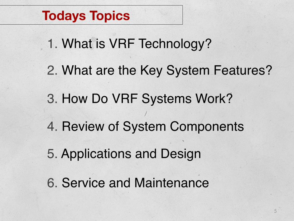
Todays Topics
! ! !1. What is VRF Technology?!
! ! !2. What are the Key System Features?!
! ! !3. How Do VRF Systems Work?!
! ! !4. Review of System Components!
! ! !5. Applications and Design!
! ! !6. Service and Maintenance!

6
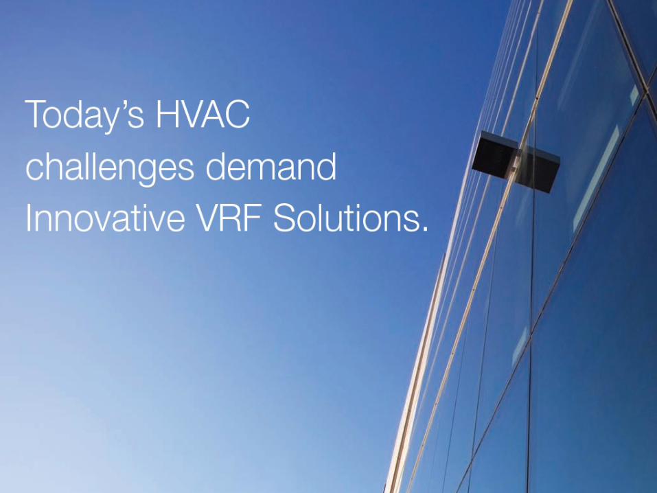
Introduction to VRF?
VARIABLE REFRIGERANT FLOW
7
8
9
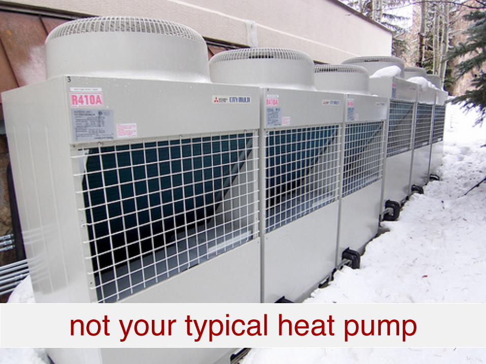
not your typical heat pump!
10
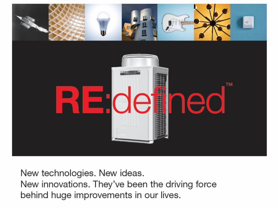
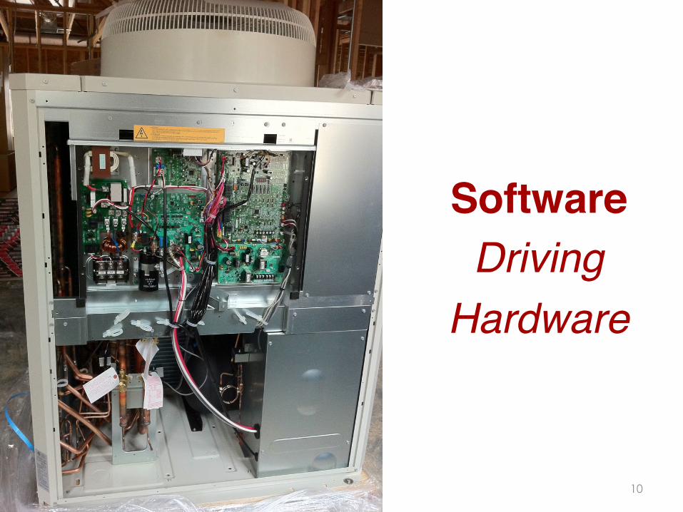
Software !Driving !
Hardware!
11
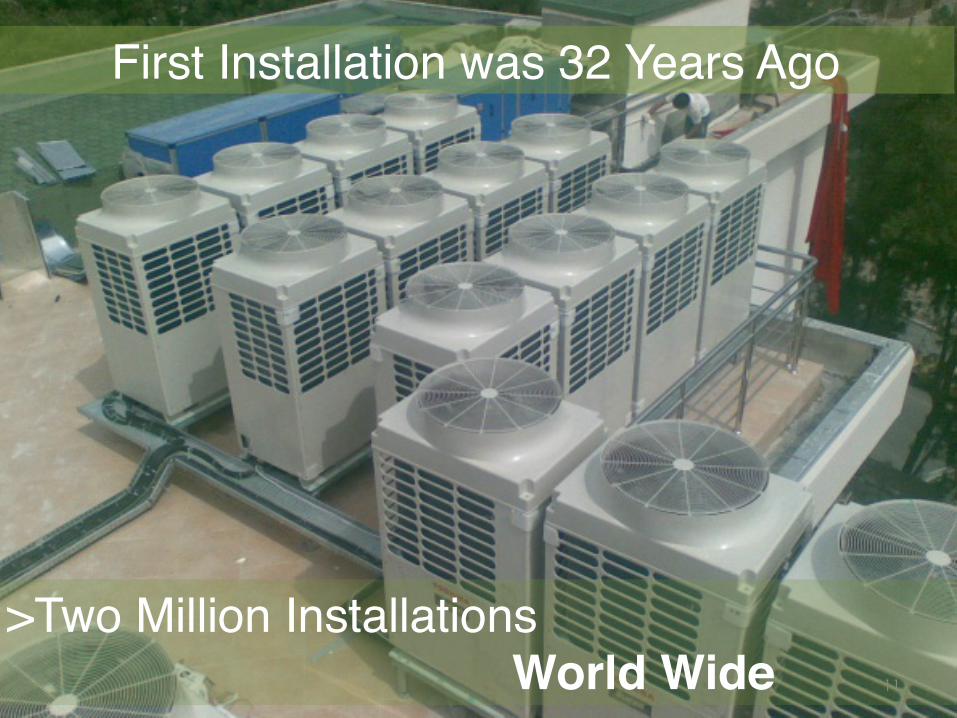
First Installation was 32 Years Ago!
>Two Million Installations! World Wide!

12
Chapter 18. Variable Refrigerant Flow
Proven Technology
Mitsubishi Electric!LG Electronics!Daikin!Panasonic/Sanyo!Fujitsu!Hitachi!Carrier/Toshiba!
13
Samsung!EMI/Enviromaster!
Midea!Gree!MHI!
Sharp!about 10 more….!
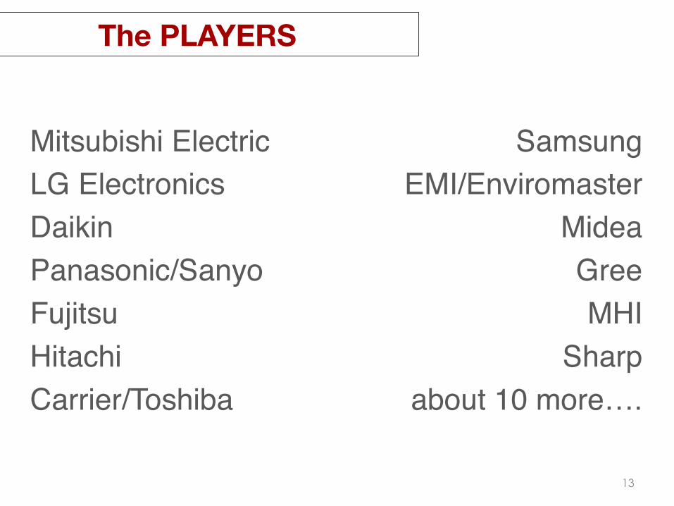
The PLAYERS
Mitsubishi Electric!LG Electronics!Daikin!Panasonic/Sanyo!Fujitsu!Hitachi!Carrier/Toshiba!
14
Samsung!EMI/Enviromaster!
Midea!Gree!MHI!
Sharp!about 10 more….!
The PLAYERS
Mitsubishi Electric!LG Electronics!Daikin!Panasonic/Sanyo!Fujitsu!Hitachi!Carrier/Toshiba!
15
Samsung!EMI/Enviromaster!
Midea!Gree!MHI!
Sharp!about 10 more….!
The PLAYERS
16
What is VRF?
A system of singular or modular heat pumps !and indoor fan coils that are connected !
by a common system control and !a common set of refrigerant piping.!
!

17
What is VRF?
A system of singular or modular heat pumps !and indoor fan coils that are connected !
by a common system control and !a common set of refrigerant piping.!
!

18
What is VRF?
A system of singular or modular heat pumps !and indoor fan coils that are connected !
by a common system control and !a common set of refrigerant piping.!
!
19
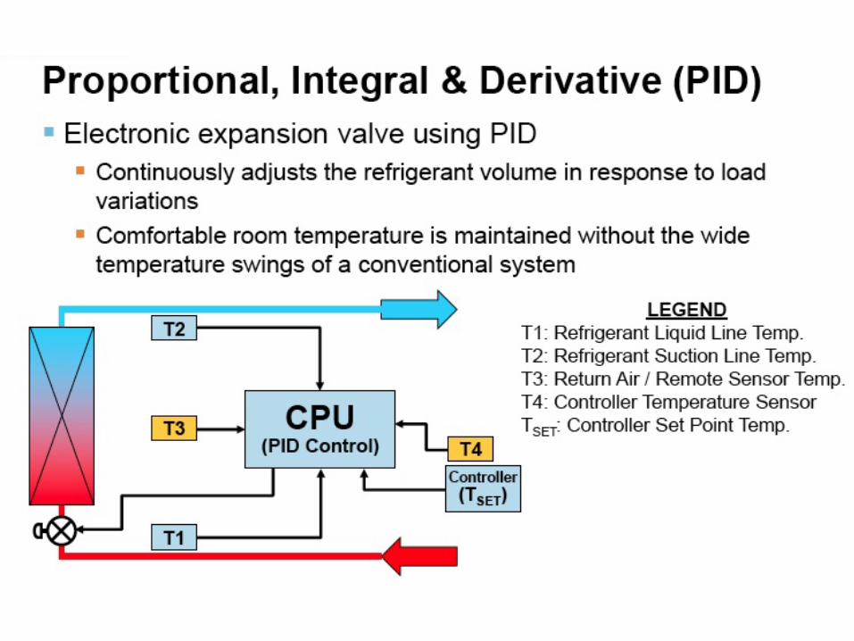
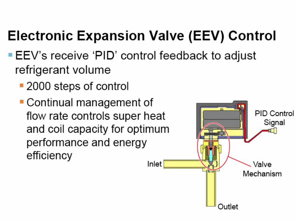
The refrigerant is passed through a series of !fan coils by means of variable speed
compressors and metered by an !electronic expansion valve (EEV) that !
regulates refrigerant flow to !accommodate the comfort set point !
for individual fan coils and zones!
What is VRF?
20
!The variable speed compressor increases!
or decreases the system capacity to !satisfy the individual load requirements!
What is VRF?

21
!The variable speed compressor increases!
or decreases the system capacity to !satisfy the individual load requirements!
What is VRF?
Personalized zoned comfort control
22
!The software programming in the outdoor unit
continually scans about 250 data points to!meet specific tolerances in target temperatures
and pressures.!
What is VRF?
the software is a conductor in a sophisticated symphony
23
Heat Pump vs. Heat Pump with Heat Recovery
24
Heat Pump vs. Heat Pump with Heat Recovery

25
Heat Pump

26
Heat Pump

27
Heat Pump
28
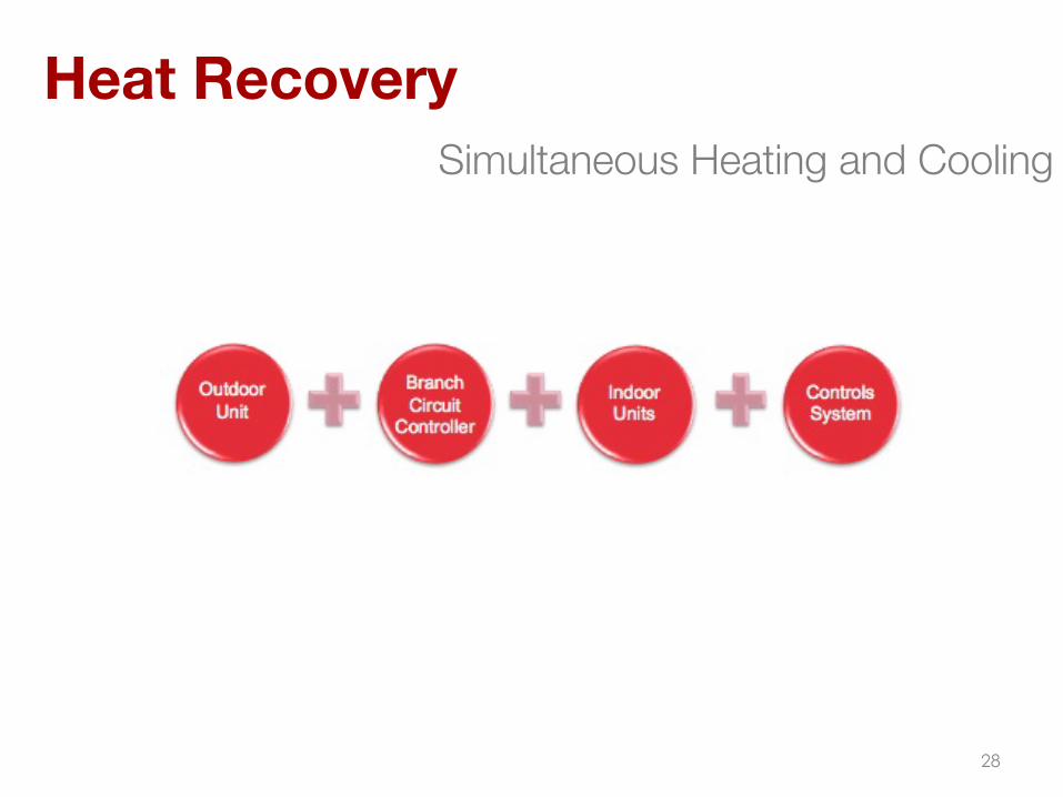
Heat Recovery Simultaneous Heating and Cooling
29
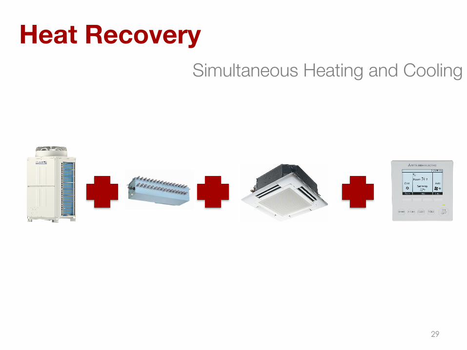
Simultaneous Heating and Cooling
Heat Recovery
30
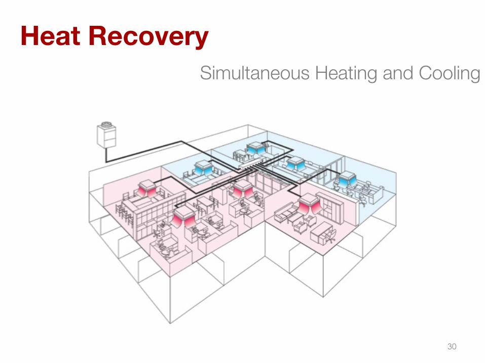
Simultaneous Heating and Cooling
Heat Recovery

31
Common Network Refrigerant Circuit and Control Communication Buss
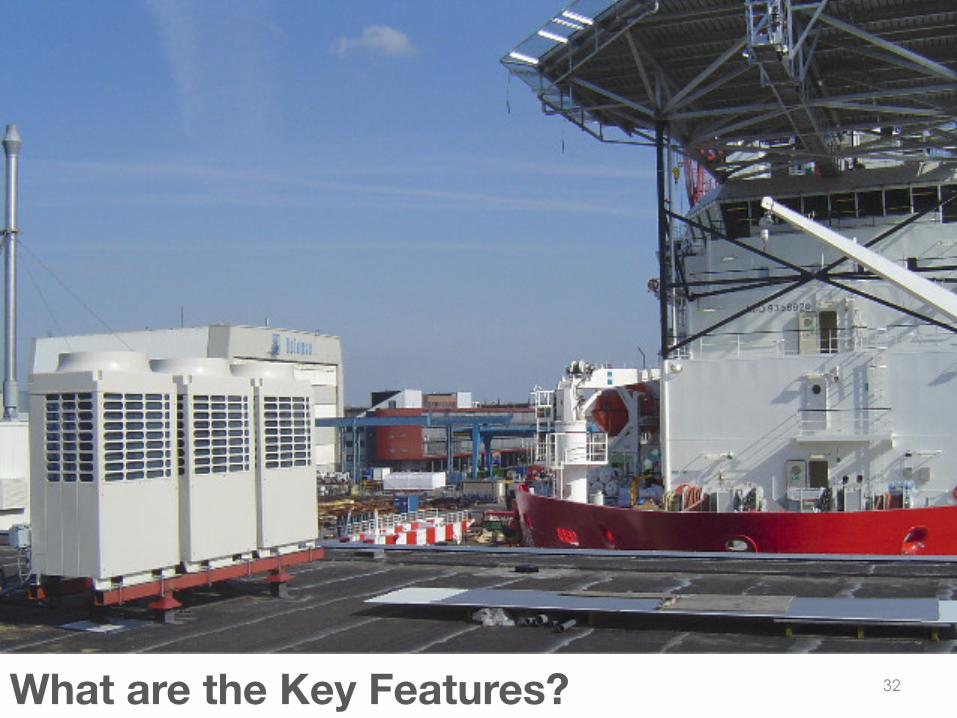
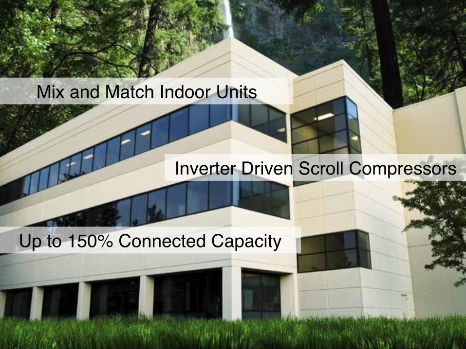
32 What are the Key Features?
33
Mix and Match Indoor Units!
Inverter Driven Scroll Compressors!
Up to 150% Connected Capacity!
34
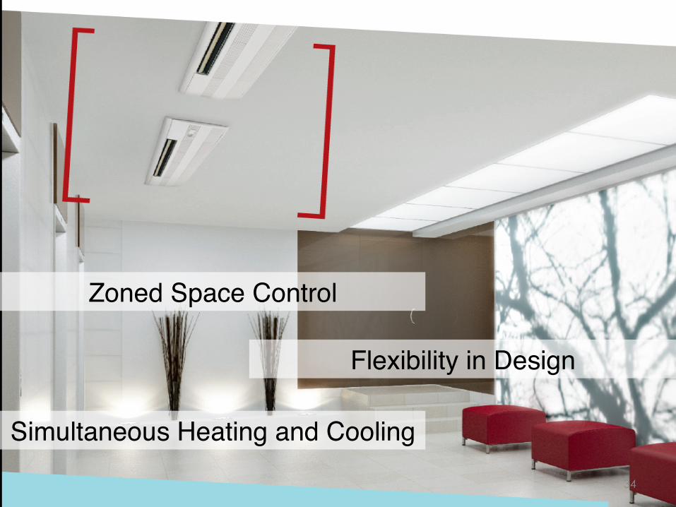
Flexibility in Design!
Zoned Space Control!
Simultaneous Heating and Cooling!
35
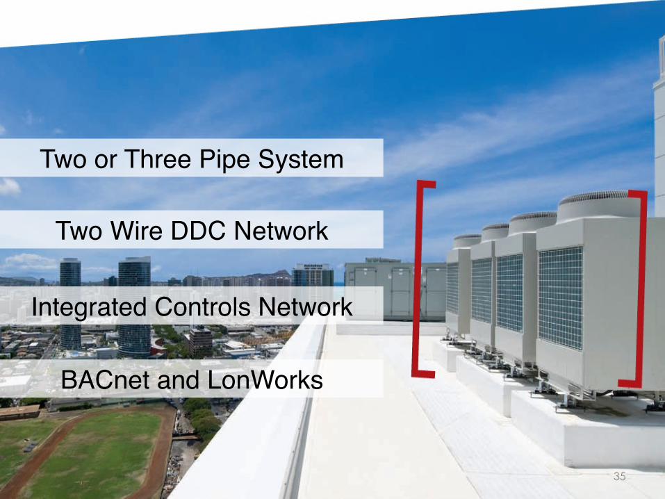
Two or Three Pipe System!
Two Wire DDC Network!
Integrated Controls Network!
BACnet and LonWorks!
36
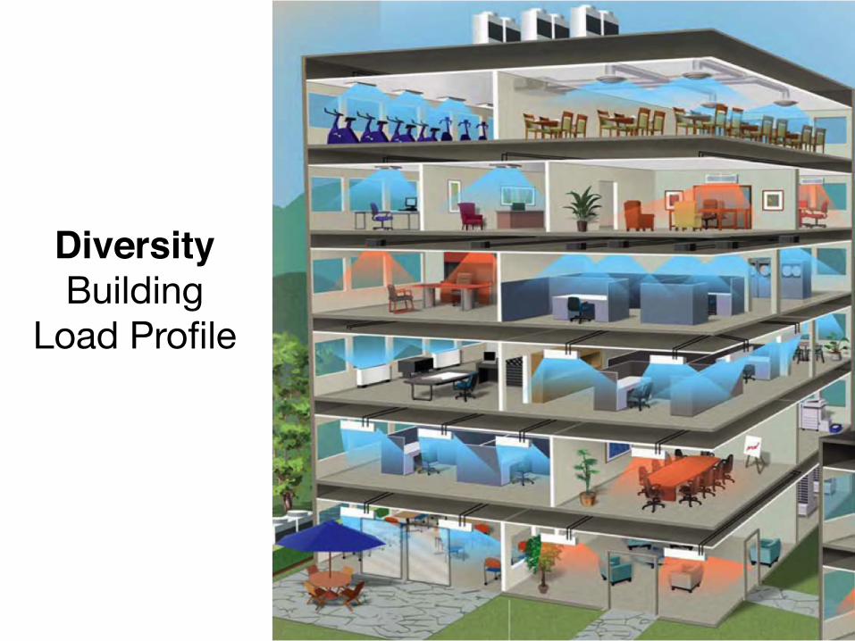
Diversity!Building
Load Profile
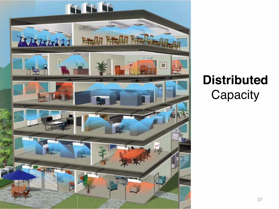
37
Distributed Capacity!

38
Flexible Piping Design
3280 FT
295 FT 49 FT
295 FT 540 FT

39
8 inches Tall

80 Tons
Economy of Scale

Economy of Scale
Fits into a Six Person Elevator

Air 30” Diameter
Ductwork
Water 2 1/2” Iron Pipe
2” Iron Pipe
Refrigerant R410A 1 1/8” Copper Pipe
Space required to deliver 20 tons of cooling
Economy of Scale

Air .3 Watts/kg
Water 5.8 Watts/kg
Refrigerant R410A 57 Watts/kg
Economy of Scale

Air .3 Watts/kg
Water 5.8 Watts/kg
Refrigerant R410A 57 Watts/kg
Economy of Scale
Transporting expensively generated conditioned air Is probably not the best method to heat and cool a building
Refrigerant has 10x the heat transfer capacity of chilled water and 190x that of air
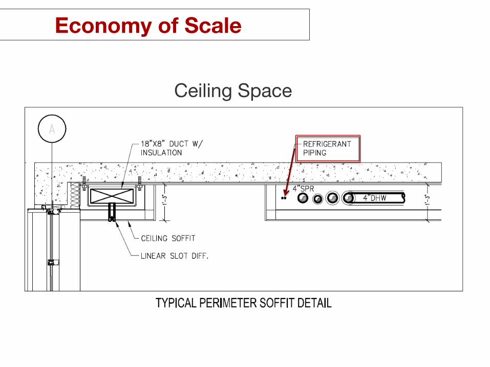
Ceiling Space
Economy of Scale
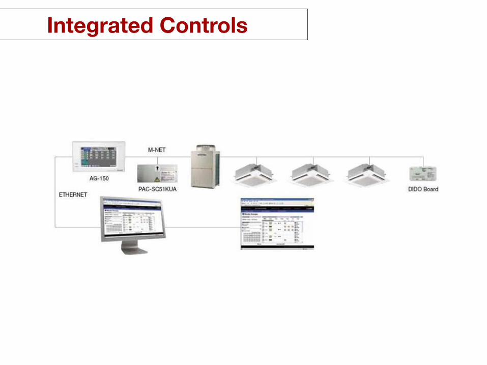
Integrated Controls

Low Sound Rating
VRF Heat Pump
VRF Indoor Units
48
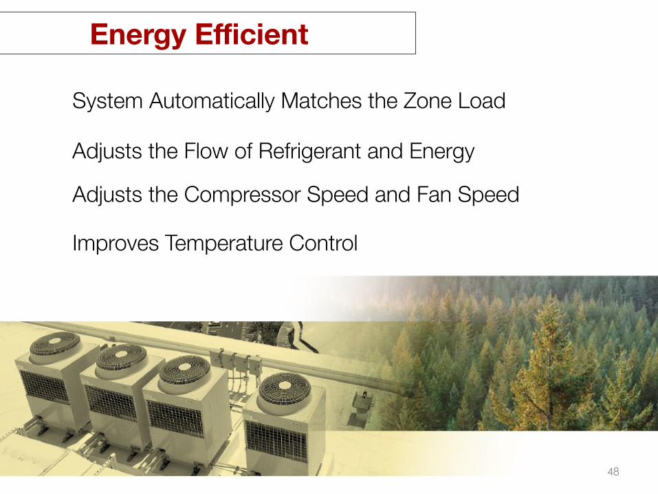
System Automatically Matches the Zone Load
Adjusts the Flow of Refrigerant and Energy
Adjusts the Compressor Speed and Fan Speed
Improves Temperature Control
Energy Efficient

49
off the charts energy efficiency when in part load conditions
Inverter driven compressor matches compressor speed to meet the full or part load demand
soft starts no lock rotor amps

50
allows for precise temperature and humidity control
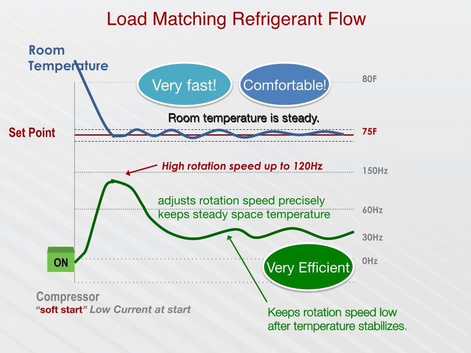
Room Temperature
Set Point 75F
60Hz
Compressor
0Hz
150Hz
30Hz
Room temperature is steady.
High rotation speed up to 120Hz
Keeps rotation speed low after temperature stabilizes.
adjusts rotation speed precisely keeps steady space temperature
80F
ON Very Efficient
Comfortable! Very fast!
Load Matching Refrigerant Flow
“soft start” Low Current at start
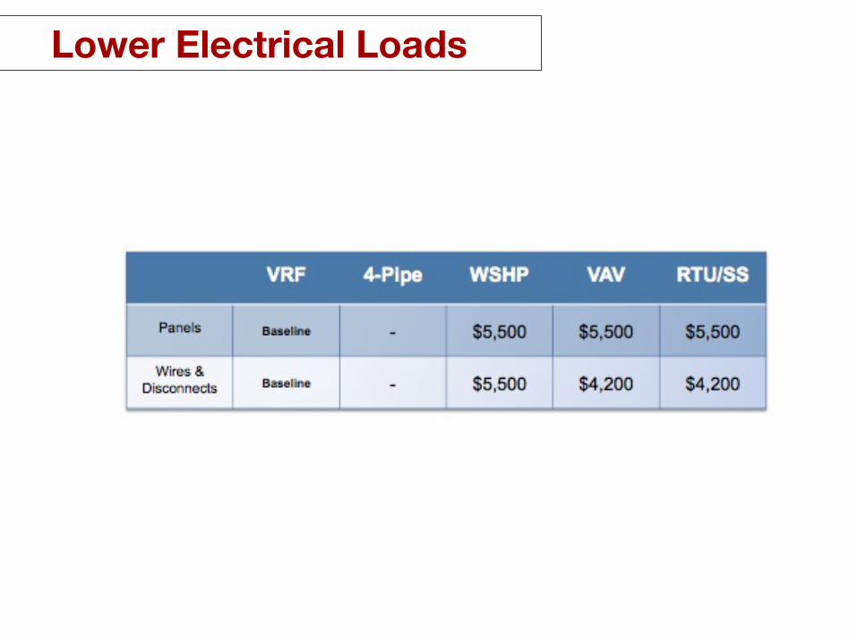
Lower Electrical Loads
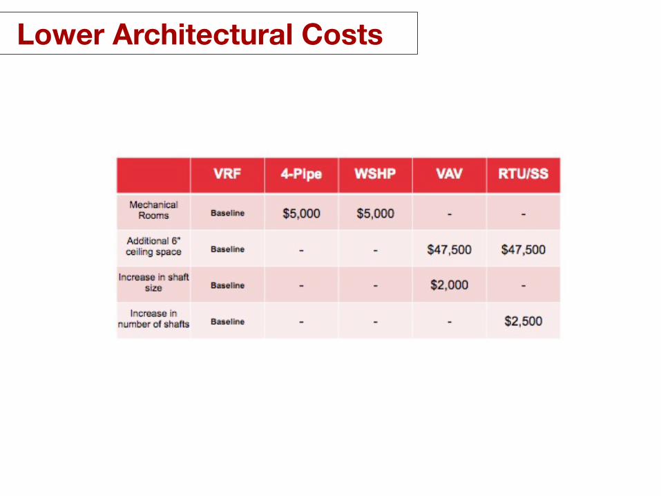
Lower Architectural Costs

Lower Structural Costs

Total Building First Costs
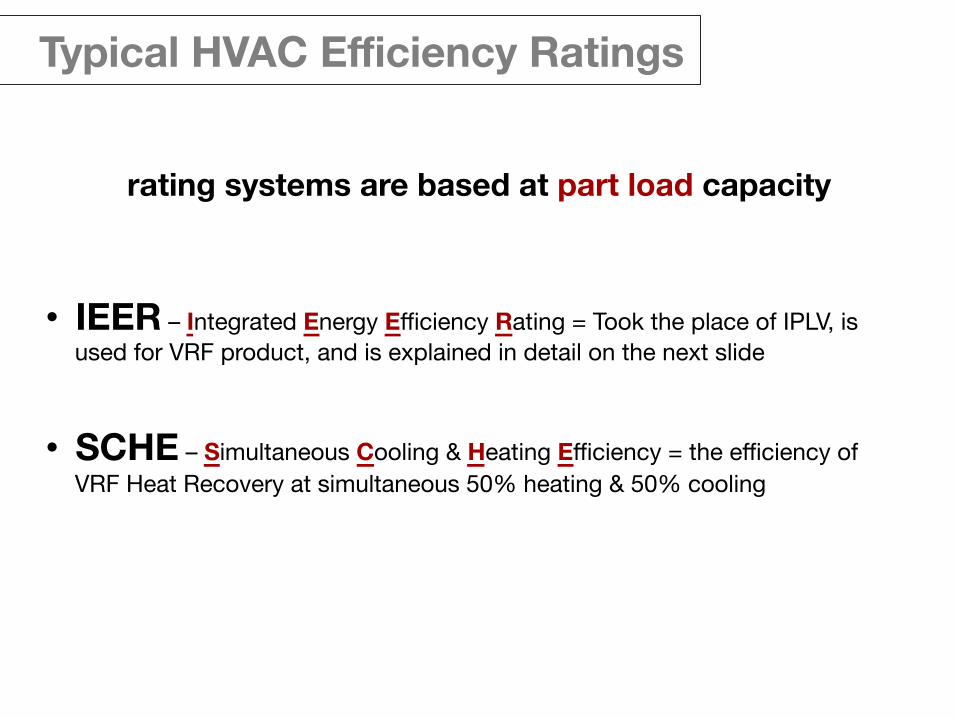
Typical HVAC Efficiency Ratings
rating systems are based at part load capacity
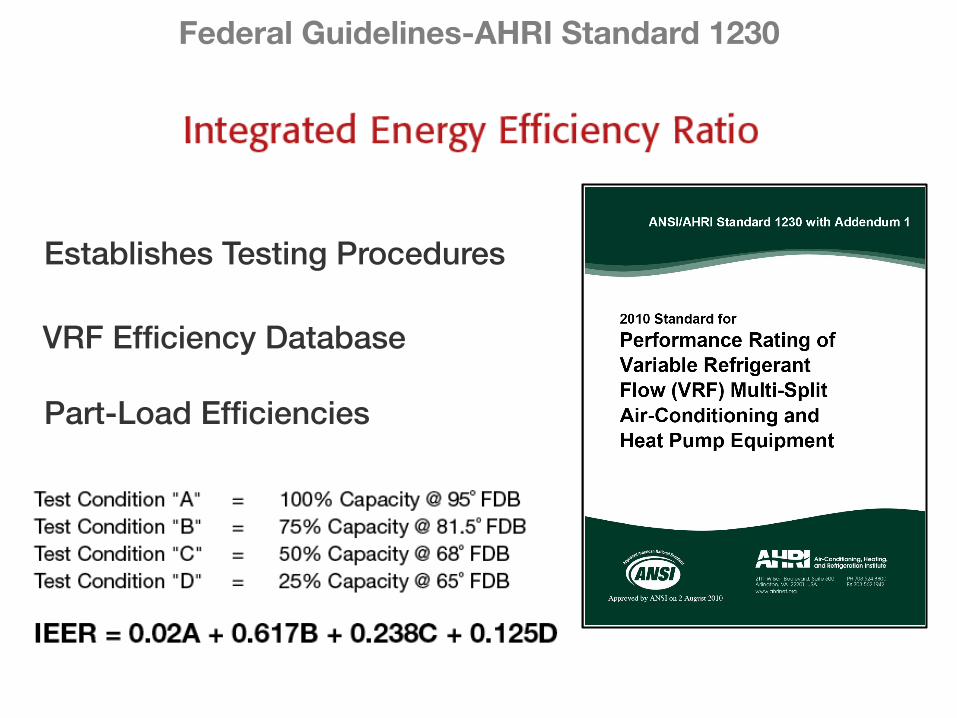
• IEER – Integrated Energy Efficiency Rating = Took the place of IPLV, is used for VRF product, and is explained in detail on the next slide
• SCHE – Simultaneous Cooling & Heating Efficiency = the efficiency of VRF Heat Recovery at simultaneous 50% heating & 50% cooling
Schematic Design Phase System Benefits
Federal Guidelines-AHRI Standard 1230
!Establishes Testing Procedures""
""! "
"
!VRF Efficiency Database ""
"! "
"
!Part-Load Efficiencies""
"! "
"

58
59
If installed correctly,!VRF systems are bullet proof.!
!-Large Texas Based Commercial Contractor!
“ ”
.05% (Five Hundredths of One Percent) Warranty Return
Reliability

Lower Life Cycle

Lower Life Cycle
the cost of an hvac system is about more than the cost of design, equipment and installation.
you need to consider operation, service, maintenance and replacement in the total cost equation.
VRF zoning systems are more efficient, easier to design, takes less time to install and require significantly less maintenance than conventional hvac systems.
62
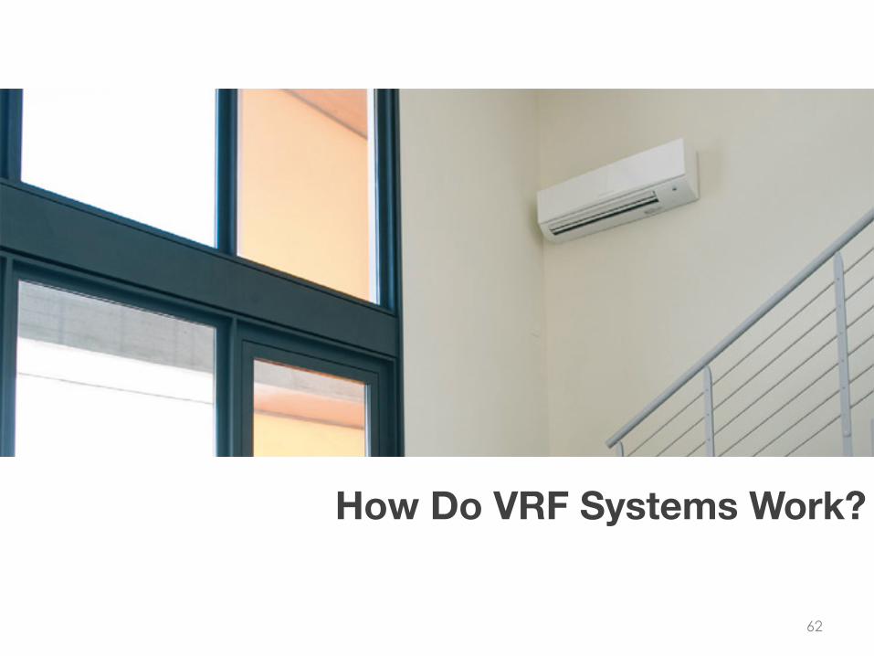
How Do VRF Systems Work?

63

LEV Coil Inet
Coil Outlet
Constantly monitoring to keep a target
Superheat or Subcooling Temperature
Return Air Stream Sensor
SMART COIL
or Room Space Sensor
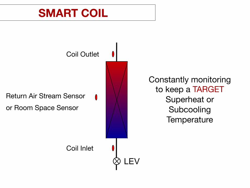
LEV Coil Inlet
Coil Outlet
Constantly monitoring to keep a TARGET
Superheat or Subcooling Temperature
Return Air Stream Sensor or Room Space Sensor
SMART COIL

SMART COIL
68
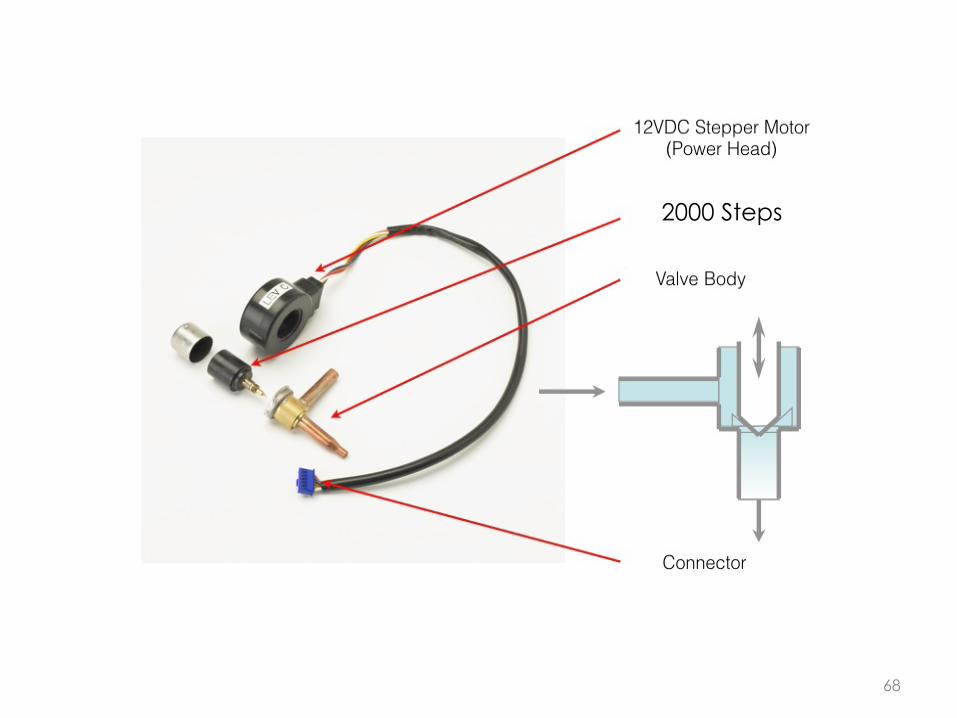
2000 Steps

70
Two vs Three Pipe Heat Recovery Systems
Inverter+Fixed or Inverter Only
Service Access to Components
Controls Network
Piping Rules
Programming Logic
DIFFERENCES IN VRF SYSTEMS
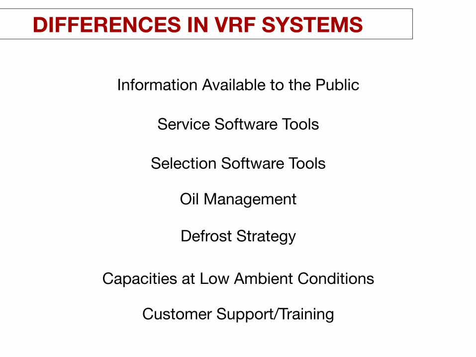
Capacities at Low Ambient Conditions
Defrost Strategy
Oil Management
Customer Support/Training
Service Software Tools
Selection Software Tools
Information Available to the Public
DIFFERENCES IN VRF SYSTEMS
72
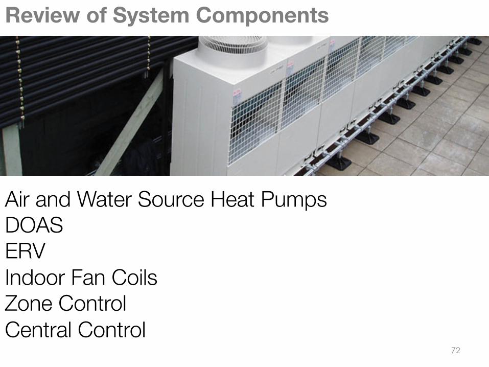
Review of System Components
Air and Water Source Heat Pumps DOAS ERV Indoor Fan Coils Zone Control Central Control

73
Air and Water Source Heat Pumps
94 Models
74
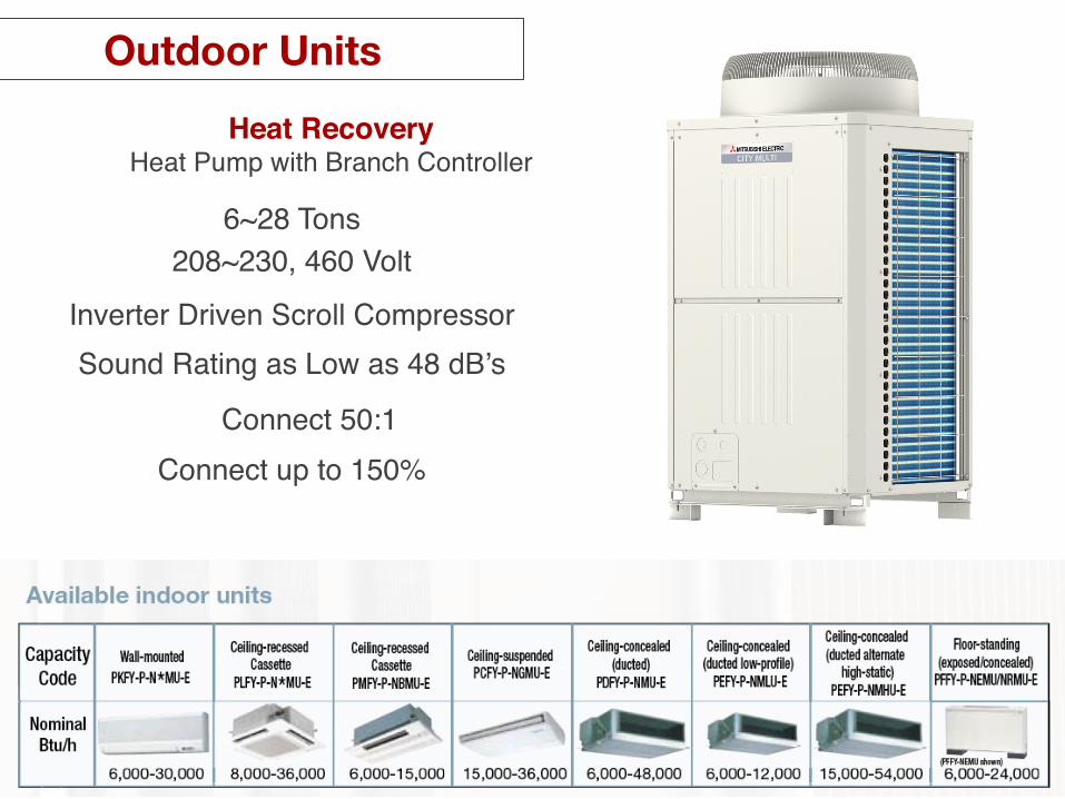
Heat Recovery !Heat Pump with Branch Controller!
6~28 Tons!208~230, 460 Volt!
Inverter Driven Scroll Compressor!Sound Rating as Low as 48 dB’s!
Outdoor Units
Connect 50:1!Connect up to 150%!
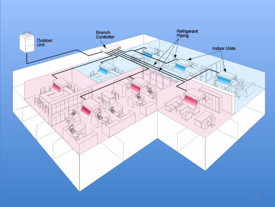
75
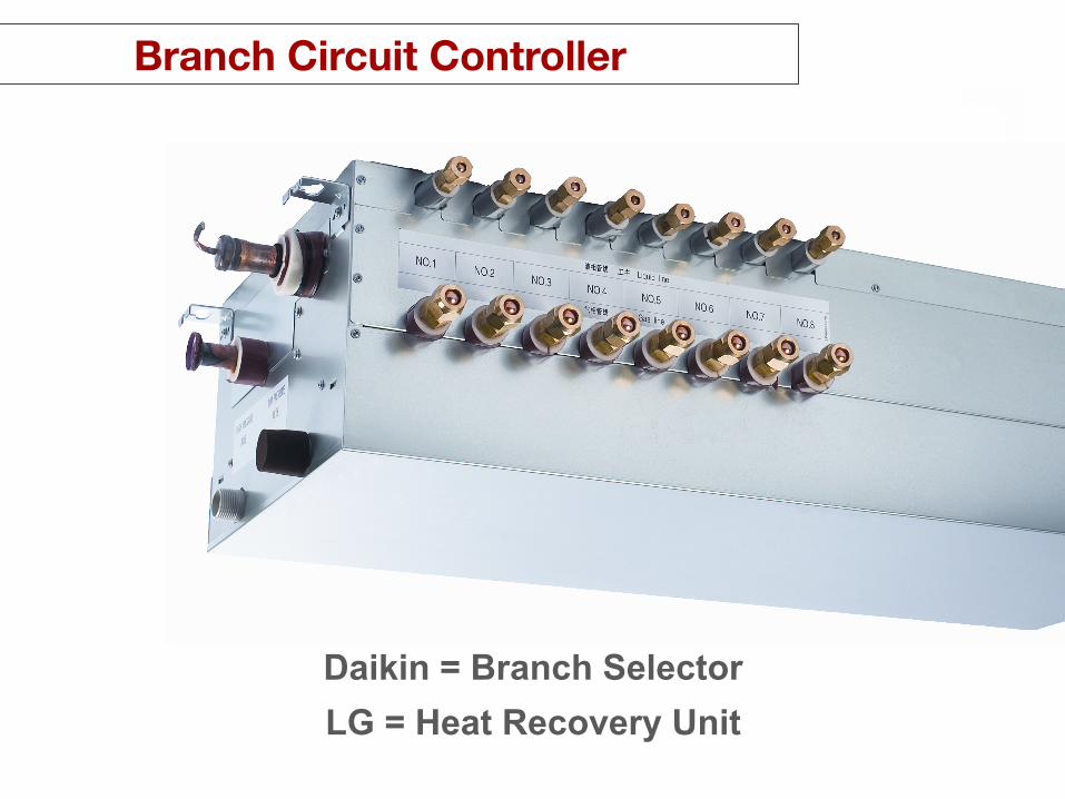
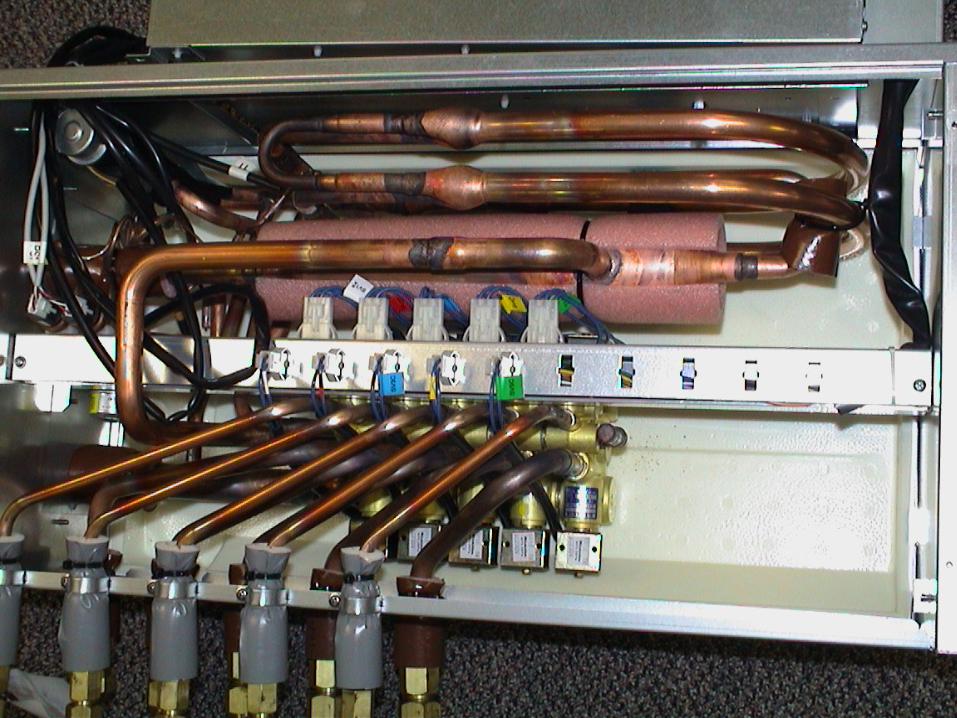
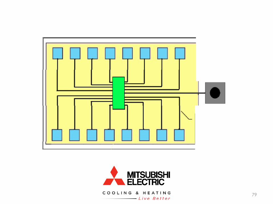
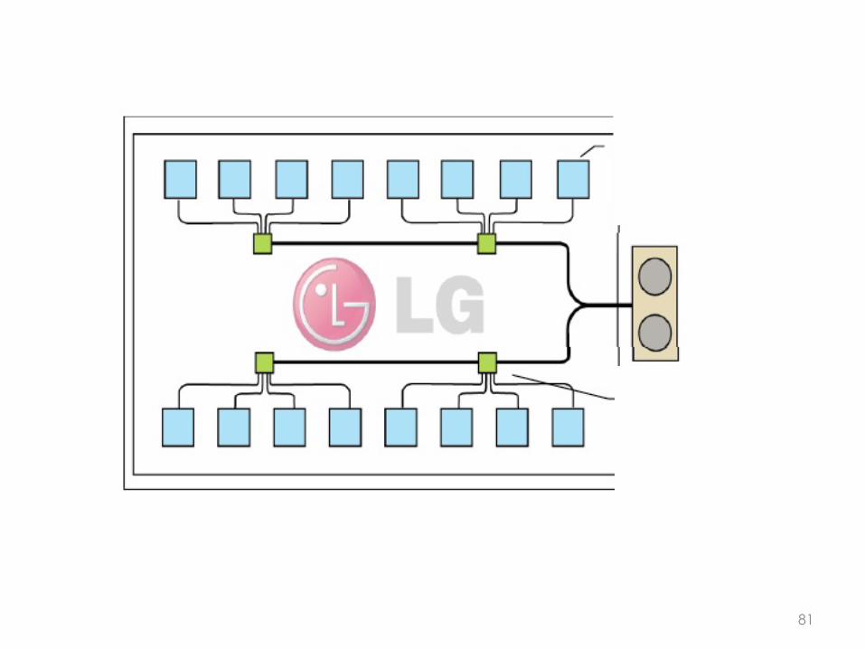
LG = Heat Recovery Unit
Branch Circuit Controller
Daikin = Branch Selector

79

80
81
82
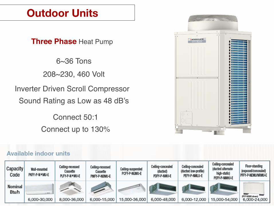
Three Phase Heat Pump!
6~36 Tons!208~230, 460 Volt!
Inverter Driven Scroll Compressor!Sound Rating as Low as 48 dB’s!
Connect 50:1!Connect up to 130%!
Outdoor Units

83
84
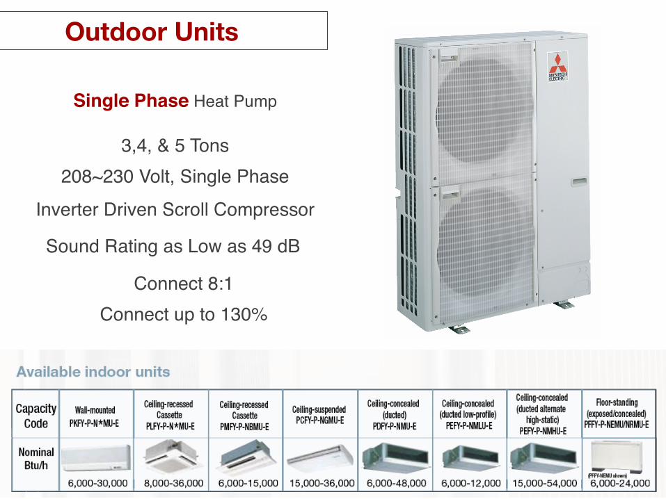
3,4, & 5 Tons!208~230 Volt, Single Phase!
Inverter Driven Scroll Compressor!
Sound Rating as Low as 49 dB!
Single Phase Heat Pump!
Connect up to 130%!Connect 8:1!
Outdoor Units

85
Indoor Units
11 Styles and 64 Models

Space Mounted Units
High Wall Mounted Ceiling Suspended
Floor Standing (PFFY-NRMU for recessed mounting not shown)
CITY MULTI VRF

Four Way 33x33 Ceiling Cassette Four Way 24x24 Ceiling Cassette
One Way Cassette
CITY MULTI VRF
Ceiling Recessed Cassettes

Concealed Ducted Units
Ceiling Concealed Medium Static Up to .6 In W.C. High Static up to 1 In W.C. Low Profile Up to .2 In W.C.
Fan Coil Down/Horizontal Left/ Vertical Ducted
Product Review CITY MULTI VRF
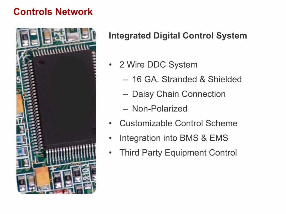
Integrated Digital Control System • 2 Wire DDC System
– 16 GA. Stranded & Shielded
– Daisy Chain Connection
– Non-Polarized
• Customizable Control Scheme
• Integration into BMS & EMS
• Third Party Equipment Control
Controls Network
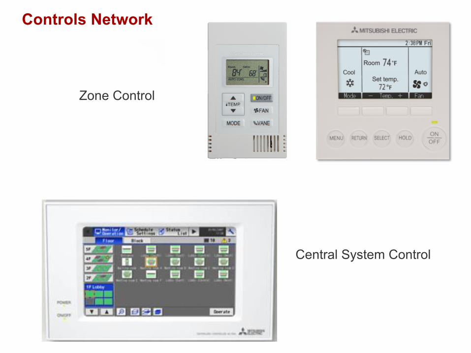
Controls Network
Zone Control
Central System Control
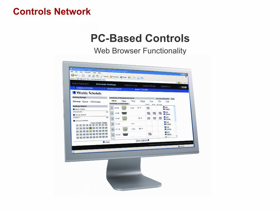
PC-Based Controls Web Browser Functionality
Product Review CITY MULTI VRF
Controls Network

CITY MULTI VRF
iPhone, iPad, iTouch App
Controls Network

IN
P1 P2 F1 F2 P1 P2 F1 F2 P1 P2 F1 F2
P1 P2 F1 F2 P1 P2 P1 P2
Zone 1
Zone 2
Zone 3
Typical Controls Wiring
System Design
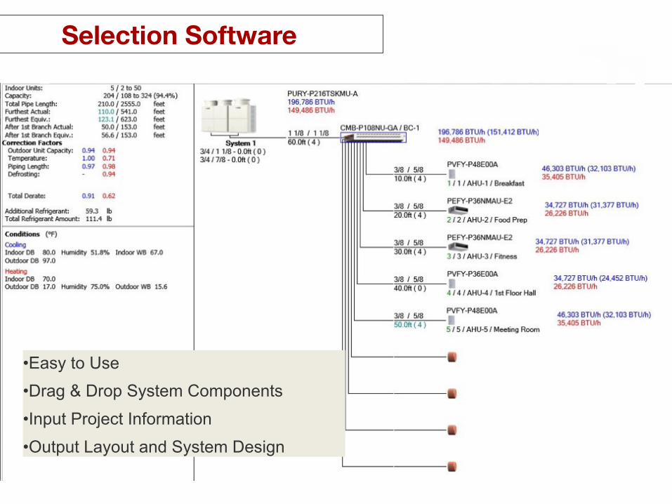
Selection Software
• Easy to Use • Drag & Drop System Components
• Input Project Information
• Output Layout and System Design
Selection Software
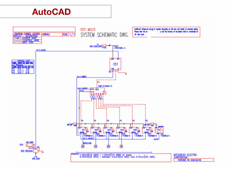
Document Design Phase System Design
AutoCAD Output AutoCAD

96
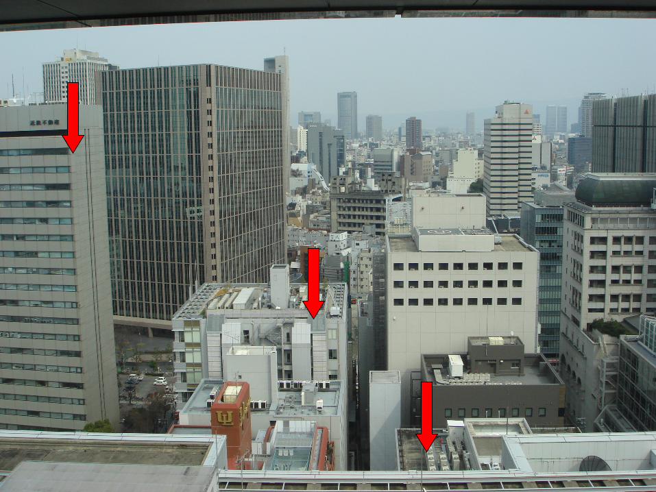
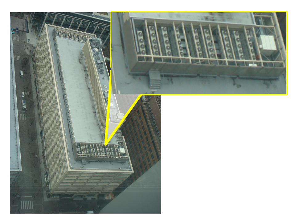
Target Applications!

99

100

101
College Dormitory!

102


104

105
Churches!
Hotels!
Hospitals!

106
Reduced Electrical Panel from 5kVA to 2kVA!
Dallas, Texas!The Element Hotel!
System is Activate by a Key Card!
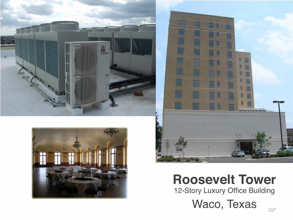
107 Waco, Texas!
Roosevelt Tower!12-Story Luxury Office Building!

108 Oklahoma City, OK!
SandRidge Energy!30-Story Office Building!
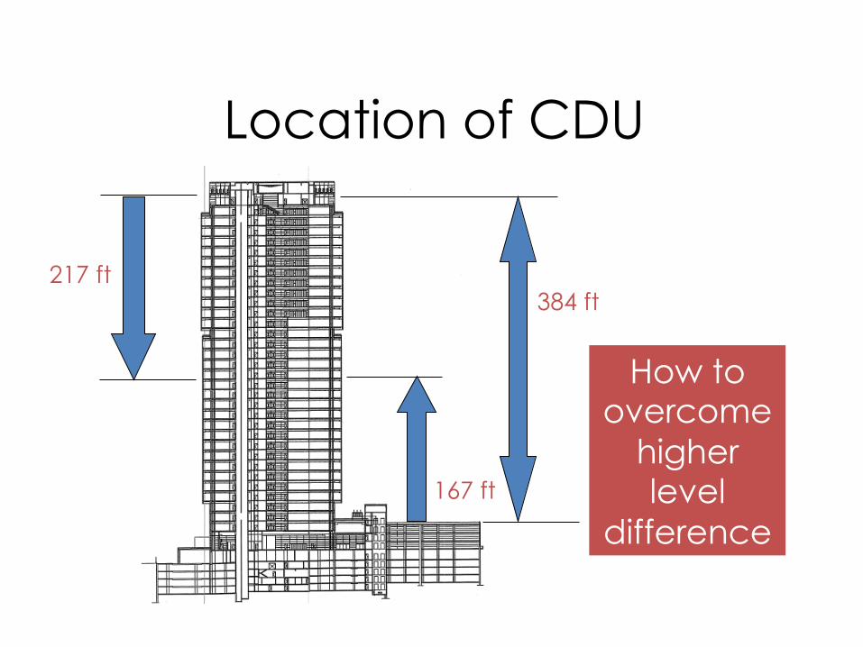
Location of CDU
217 ft
167 ft
How to overcome
higher level
difference
384 ft
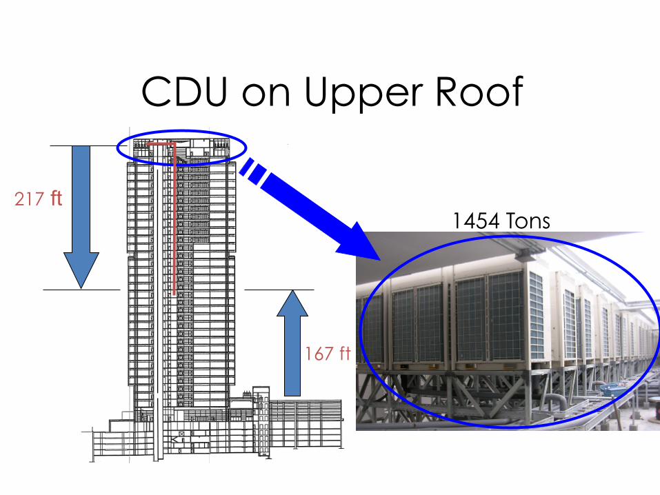
CDU on Upper Roof
217 ft
167 ft
1454 Tons

CDU on Lower Roof
217 ft
167 ft 1259 Tons

113
[ Custom Home ]!

114
115
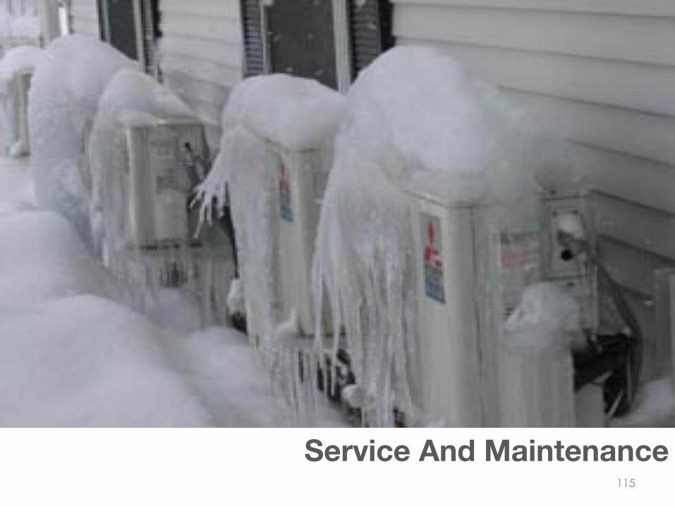
Service And Maintenance
116
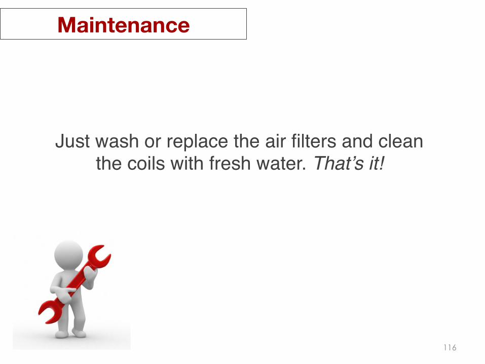
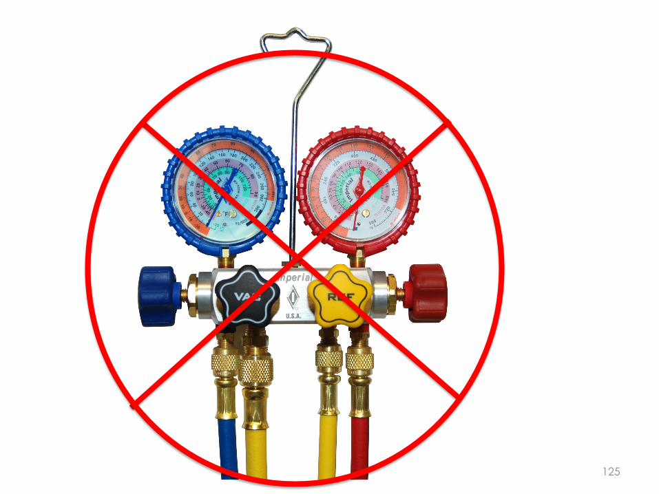
Just wash or replace the air filters and clean the coils with fresh water. That’s it!!
Maintenance

117
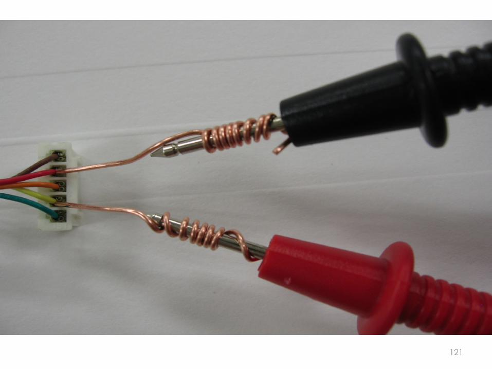
The number one thing you need when!troubleshooting a VRF or DFS system is…….!
Service

118
119

120
121

122
DC Voltmeter!Selectable!
Range up to!500k Ohm!
Ohm-meter!
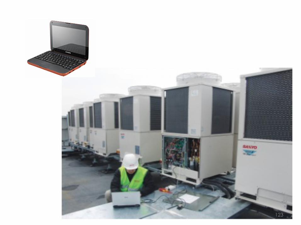
123

124
125
126
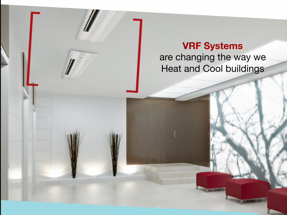
VRF Systems are changing the way we Heat and Cool buildings

Open Forum 128