introduction to tmn - bme-hitjakab/edu/litr/tmn/tmn_tutorial.pdf · introduction to tmn 2...
TRANSCRIPT

Introduction to TMN
Aiko Pras, Bert-Jan van Beijnum, Ron Sprenkels
CTIT Technical Report 99-09
April 1999
University of Twente
The Netherlands
Copyright © 1999 by Aiko Pras, Enschede, The Netherlands
This tutorial has been produced as part of the Internet Next Generation project and may be used for educational purposes, under the condition that the source of this tutorial will be acknowledged.The HTML version of this tutorial can be found at: http://wwwsnmp.cs.utwente.nl/tutorials/tmn/

Introduction to TMN
Introduction to TMN
The term TMN is introduced by the ITU-T (the former CCITT) as an abbreviation for ‘Telecom-munications Management Network’. The concept of a TMN is defined by RecommendationM.3010. TMN has a strong relationship with OSI management, and defines a number of con-cepts that have relevance for Internet Management.
According to M.3010, “a TMN is conceptually a separate network that interfaces a telecommu-nications network at several different points”. The relationship between a TMN and the tele-communication network that is managed, is shown in Figure 1. According to this figure, theinterface points between the TMN and the telecommunication network are formed byExchanges and Transmission systems. For the purpose of management, these Exchangesand Transmission systems are connected via a Data Communication Network to one or moreOperations Systems. The Operations Systems perform most of the management functions;these functions may be carried out by human operators but also automatically. It is possiblethat a single management function will be performed by multiple Operations Systems. In thiscase, the Data Communication Network is used to exchange management informationbetween the Operation Systems. The Data Communication Network is also used to connectWork Stations, which allow operators to interpret management information. Work Stations haveman-machine interfaces, the definition of such interfaces fall outside the scope of TMN (WorkStations are therefore drawn at the border of the TMN).
Recommendation M.3010 defines the general TMN management concepts and introducesseveral management architectures at different levels of abstraction:• A functional architecture, which describes a number of management functions.• A physical architecture, which defines how these management functions may be imple-
mented into physical equipment.• An information architecture, which describes concepts that have been adopted from OSI
management.• A logical layered architecture (LLA), which includes one of the best ideas of TMN: a model
that shows how management can be structured according to different responsibilities.
Operations
System
Figure 1: General relationship of a TMN to a telecommunication network
Operations
System
Telecommunication network
TMN
Operations
System
WorkStation
ExchangeTransmission
systemsExchange
Transmission
systemsExchange
Data Communication Network
2

TMN standardization
1 TMN standardization
The TMN standardization started in 1985 by CCITT Study Group IV [1]. The first TMN recom-mendation was called M.30 [2] and was published in 1988 as part of the blue books. In 1992 acompletely revised version appeared and the number of the recommendation was changedinto M.3010. This version changed again in 1996 [4].As compared to the 1988 version of M.30, the 1992 version of M.3010 removed the sectionson ‘Planning and Design’ (which became an appendix) and on ‘Functions associated withTMN’. The 1992 version added also a number of new sections, such as those on the ‘TMNInformation Architecture’. The most important changes of the 1996 version relate to ‘TMN’sLogical Layered Architecture’.
Since 1988 a number of related recommendations have been defined. These recommenda-tions refine specific aspects of TMN and use M.3010 as the architectural basis (see Figure 2).In addition, a large number of TMN recommendations were defined for ISDN management.
TMN managementcapabilities at the
X interface: M.3320
Figure 2: Relation between TMN recommendations
Management service n*
Overview ofTMN Recommendations
M.3000
Terms and definitionsTMN
M.60 §2
Principles for aTMN
M.3010
TMN interfacespecification methodology
M.3020
TMN managementfunctionsM.3400
Generic network informationmodel for TMN
M.3100
Catalogue of TMNmanagement information
M.3180
Management service 1*
TMN managementservices: overview
M.3200
TMN managementcapabilities at the
F interface: M.3300
3

TMN standardization
1.1 Basic TMN recommendations
Figure 3 shows the list of TMN recommendations, including the last modification date.
1.2 TMN recommendations for ISDNFigure 4 shows the list of TMN recommendations for (broadband) ISDN, including the last mod-ification date.
Title NUMBER DATE
Overview of TMN Recommendations M.3000 10/94
Principles for a TMN M.3010 05/96
TMN interface specification methodology M.3020 07/95
Generic network information model M.3100 07/95
Managed object conformance statements for the generic network inf. model M.3101 07/95
Catalogue of TMN management information M.3180 10/92
TMN Management Services: Overview M.3200 10/92
TMN management Services: Maintenance aspects of B-ISDN management M.3207.1 05/96
TMN management Services: Fault and performance mgt. of the ISDN access M.3211.1 05/96
TMN management capabilities presented at the F interface M.3300 10/92
Management requirements framework for the TMN X-interface M.3320 04/97
TMN management functions M.3400 04/97
Figure 3: TMN related recommendations
Title NUMBER DATE
Principles for the management of ISDNs M.3600 10/92
Application of maintenance principles to ISDN subscriber installations M.3602 10/92
Application of maintenance principles to ISDN basic rate access M.3603 10/92
Application of maintenance principles to ISDN primary rate access M.3604 10/92
Application of maintenance principles to static multiplexed basic rate access M.3605 10/92
Principles for applying the TMN concept to the management of B-ISDN M.3610 05/96
Test management of the B-ISDN ATM layer using the TMN M.3611 04/97
Principles for the use of ISDN test calls, systems and responders M.3620 10/92
Integrated management of the ISDN customer access M.3621 07/95
Management of the D-channel - Data link layer and network layer M.3640 10/92
Management information model for the management of the data link and network layer of the ISDN D channel M.3641 10/94
Network performance measurements of ISDN calls M.3650 04/97
ISDN interface management services M.3660 10/92
Figure 4: TMN recommendations for ISDN
4

TMN Functional Architecture
2 Functional Architecture
Five different types of function blocks are defined by TMN’s functional architecture. It is not nec-essary that all of these types are present in each possible TMN configuration. On the otherhand, most TMN configurations will support multiple function blocks of the same type.
Figure 5 has been copied from the TMN recommendations and shows all five types of functionblocks1. In this figure, two types (OSF and MF) are completely drawn within the box labelled‘TMN’. This way of drawing indicates that these function blocks are completely specified by theTMN recommendations. The other three types (WSF, NEF and QAF) are drawn at the edge ofthe box to indicate that only parts of these function blocks are specified by TMN. Subsection2.1 until Subsection 2.5 give short descriptions these five function blocks.
The TMN functional architecture introduces the concept of reference point to delineate functionblocks. Five different classes of reference points are identified. Three of them (q, f and x) arecompletely described by the TMN recommendations; the other classes (g and m) are locatedoutside the TMN and only partially described.
Figure 6 provides an example of reference points and function blocks. The picture shows forinstance that the Mediation Function (MF) can be reached via q reference points and that them reference point can be used to reach the Q Adaptor Function (QAF) from outside TMN.
1. To avoid adventitious interpretations, it was decided to copy as far as possible drawings from Recom-mendation M.3010.
Figure 5: TMN Function blocks
MF
TMN
OSF
TMN Function blocks:
OSF = Operations System FunctionsMF = Mediation FunctionsWSF = Work Station FunctionsNEF = Network Element FunctionsQAF = Q Adaptor Functions
NEF
WSF
QAF
Figure 6: Example of reference points between function blocks
TMN
f g
m
q q
q
= reference point
x
TMN
WSFOSF
MF
NEFQAF
OSF
5

TMN Functional Architecture
2.1 Network Element FunctionsA typical telecommunication network consists of exchanges and transmission systems. In TMNterminology, exchanges and transmission systems are examples of network elements (NEs).The functions that are performed by NEs are ‘Network Element Functions’ (NEFs). Accordingto TMN, these functions include:• Primary (or telecommunications) functions. These functions are the subject of management
and support the exchange of data between the users of the telecommunication network.• Management functions, which allow the NEF block to operate in an agent specific role.As opposed to the second kind, the first kind of functions are not further defined by TMN. Thisexplains why Figure 5 locates the NEF at the edge of the TMN.
2.2 Operations System FunctionsThe Operations System Functions (OSF) block initiates management operations and receivesnotifications. In terms of the manager-agent model, the OSF may be seen as the manager spe-cific functions. An OSF communicates with the NEF over a q3 reference point (Figure 7).
The initial 1988 version of M.30 defined three different q reference points: q1, q2 and q3. Theq3 reference point is used whenever management information should be exchanged via anapplication layer management protocol, such as the Common Management Information Proto-col (CMIP [6]) of OSI. The two other reference points were intended for cases in which man-agement information should be exchanged via lower layer (e.g. data link) management proto-cols. After some time it appeared however that it was impossible to make a distinction betweenq1 and q2; these two reference points were therefore replaced by the generic qx reference point.
Figure 8 shows the relation between OSF, NEF and q3, expressed in terms of the OSI serviceand protocol concepts. The service provided at the q3 reference point is generally the CommonManagement Information Service (CMIS [5]).
Within a single TMN (operated by a single administration) multiple OSFs may be defined. Ifnecessary, these OSFs can communicate with each other over q3 reference points. It is alsopossible that OSFs in different TMNs (operated by different administrations) communicate witheach other; in this case communication takes place over a x reference points.
q3
NEF
Figure 7: OSF and NEF
OSF
Figure 8: Relation between OSF, NEF and q3, expressed in terms of OSI concepts
OSF(manager)
q3 reference point
NEF(agent)
6

TMN Functional Architecture
2.3 Work Station Functions“The Work Station Function (WSF) block provides the means to interpret TMN information forthe management information user. The WSF includes support for interfacing to a human user(at the g reference point). Such aspects of support are not considered to be part of the TMN”.Figure 5 therefore locates the WSF at the edge, and the g reference point outside the TMN.
2.4 Q Adaptor FunctionsThe Q Adaptor Function (QAF) block is used to connect to the TMN those entities which do notsupport standard TMN reference points. An example is shown in Figure 9; in this figure a non-TMN OSF and a non-TMN NEF are connected to the TMN. The responsibility of both QAFs isto translate between q reference points (which are TMN reference points) and m referencepoints. Since the m reference point is a non-TMN (e.g. proprietary) reference point, Figure 5showed the QAF at the edge of the TMN.
2.5 Mediation FunctionsThe Mediation Function (MF) block is located within the TMN and acts on information passingbetween NEFs or QAFs, and OSFs. A MF block can be used to connect a single (Figure 10),as well as multiple NEFs and QAFs to an OSF. MF blocks can also be cascaded.
Among the types of MFs that can be recognized, are those that:• Augment OSFs; examples are storage and filtering of management information.• Augment NEFs; an example is the transformation from the local representation of manage-
ment information into a standardized form.
2.6 Relationship between function blocksNow that an initial understanding of all function blocks and reference points exists, it is possibleto discern all relationships between these function blocks and reference points. This relation-ship is given in Figure 11.
Figure 9: Q Adaptor Functions
mreference
point
mreference
point
qreference
point
qreference
point
TMN QAFnon-TMN
OSF QAFnon-TMN
NEF
Figure 10: MF related to other function blocks
q3
qx
between NEF and OSF between QAF and OSF
q3
qx
NEF
MF
OSF
QAF
MF
OSF
7

TMN Functional Architecture
A function block at the top of a column may exchange management information with a functionblock at the left of a row over the reference point that is mentioned at the intersection of thecolumn and row. In case an intersection is empty, the associated function blocks can notdirectly exchange management information between each other.
2.7 Further remarksBesides the function blocks and reference points, the TMN functional architecture introducessome additional concepts. These concepts are:• TMN’s Data Communication Function• TMN’s functional components
According to recommendation M.3010, “TMN’s Data Communication Function (DCF) will beused by the function blocks for exchanging information. The DCF provides layers 1 to 3 of theOSI RM”.The definition of the DCF concept has historical reasons: in initial drafts of TMN the DCF wasmodelled as a function block; it was therefore part of TMN’s functional architecture. At presentthe DCF is no longer modelled as a function block; the text that describes the DCF remained,however.
Each of TMN’s function blocks is itself composed of a number of functional components. Thefollowing functional components are defined:• Management Application Function.• Management Information Base.• Information Conversion Function.• Human Machine Adaptation.• Presentation Function.• Message Communication Function (MCF).
Figure 11: Relation between function blocks
NEF
OSF
MF
QAFq3
QAFqx
WSF
Non-TMN
NEF OSF MF QAFq3 QAFqx WSF Non-TMN
q3 qx
q3 x*, q3 q3 q3 f
qx q3 qx qx f
q3 m
qx m
f f g**
m m g**
m, g = non TMN reference points
* = x reference point only applies when each OSF is in a different TMN** = The g reference point lies between the WSF and the human user
8

TMN Functional Architecture
These functional components can be divided into two categories:• The first five components belong to the first category. These components perform the actual
management actions; they do not address problems related to the exchange of managementinformation.
• The last component (MCF) belongs to the second category. This component is associatedwith all function blocks that require an underlying service for the exchange of their manage-ment information. "The MCF is composed of a protocol stack that allows connection of func-tion blocks to DCFs". In many cases the MCF provides the end-to-end functions such asthose found in OSI layers 4 to 7.
Recommendation M.3010 contains a picture (Figure 12) to illustrate the relation between func-tion blocks, functional components, the MCF and the DCF.
Figure 12: Function blocks, components, MCF and DCF
TMNFunctional
Components(category 1)
MCF
DCF
TMNFunctional
Components(category 1)
MCF
Peer to Peer Communication
Function BlockFunction Block
9

TMN Physical Architecture
3 Physical Architecture
Next to a functional architecture, TMN also defines a physical architecture. The latter architec-ture shows how TMN’s functions, which were defined by the functional architecture, can beimplemented into physical equipment. TMN’s physical architecture is thus defined at a lowerabstraction level than TMN’s functional architecture (Figure 13).
The physical architecture shows how function blocks should be mapped upon building blocks(physical equipment) and reference points upon interfaces. In fact, the physical architecturedefines how function blocks and reference points can be implemented (Figure 14). It should benoted however that one function block may contain multiple functional components and onebuilding block may implement multiple function blocks.
To avoid confusion between the functional and physical architecture, it is helpful to understandthe following conventions. Names of reference points are written in lower case, names of inter-faces in upper case (subscripts may be added). Reference points are drawn as small filled cir-cles (bullets), interfaces as open circles. Function blocks are shown as big circles or ellipses,building blocks are drawn as boxes.
Functional architecture defines the various TMN management functions
defines how the various TMN managementfunctions can be implemented intophysical equipment
Figure 13: TMN has defined multiple, related architectures
Physical architecture
Figure 14: Relation between TMN Architectures
functional components
function blocks
building blocks
reference points
interfaces
TMN Functional Architecture:
TMN Physical Architecture:
+
(physical equipment)
Figure 15: Drawing conventions
reference point
interface
function block
building block
10

TMN Physical Architecture
3.1 Building blocksTMN’s Physical Architecture defines the following building blocks:• Network Element (NE).• Mediation Device (MD).• Q Adaptor (QA).• Operations System (OS).• Work Station (WS).• Data Communication Network (DCN).Building blocks always implement the function blocks of the same name (e.g. Network Ele-ments perform Network Element Functions, Mediation Devices perform Mediation Functionsetc.).
It is possible to implement multiple function blocks (of the same or of a different type) into asingle building block. The Operations System, for example, may be used to implement multipleOSFs, but may also be used to implement an OSF, MF and a WSF. In the case a building blockimplements multiple function blocks of different types, "the choice on the building block’s nameis determined by the predominate usage of the block".Figure 16 shows which function blocks may be implemented into which building blocks.
A special kind of building block is the Data Communication Network (DCN). As opposed to theothers, this building block does not implement any TMN function block. In fact, the DCN is usedby other building blocks for the exchange of management information; the DCN’s task is to actas a transport network.
At first sight it seems strange that TMN defines a building block that does not implement anyfunction block. The existence of the DCN can be understood however when we remember thatprevious TMN drafts (e.g. [8]) modelled the DCF as a function block. According to these drafts,the DCF had to be implemented by a DCN and, in that case, each building block implementedat least one function block. In 1990 it was decided however to model the DCF no longer as afunction block [9]. After this decision was made, the standard was not rewritten in a consistentway and the DCN is therefore still modelled as a building block.
3.2 InterfacesInterfaces may be regarded as the implementations of TMN reference points. Whereas refer-ence points may generally be compared with underlying services, interfaces may be comparedwith the protocol stacks that implement these services.In most cases reference points and interfaces have a one to one mapping. However, no inter-faces exist for those reference points that:• interconnect function blocks that are implemented within a single building block, • lay outside TMN (g and m, see Figure 6). Implementation of these reference points is outside
the scope of TMN.
Figure 16: Relation between function blocks and building blocks
MD
OSQA
WS
NEFM
MFOM
O
QAFOO
OM
OSFOO
M
WSFO*O
OM
NE
M = MandatoryO = OptionalO* = may only be present
if OSF or MF is also presentDCN
11

TMN Physical Architecture
The naming of interfaces is also straightforward: an interface gets the same name (this timewritten in upper case) as the related reference point. Figure 17 shows all possible mappings.
Figure 17: Mapping reference points upon interfaces
reference point
interface
qx
Qx
q3
Q3
x
X
f
F
(g m)
12
TMN Information Architecture
4 Information Architecture
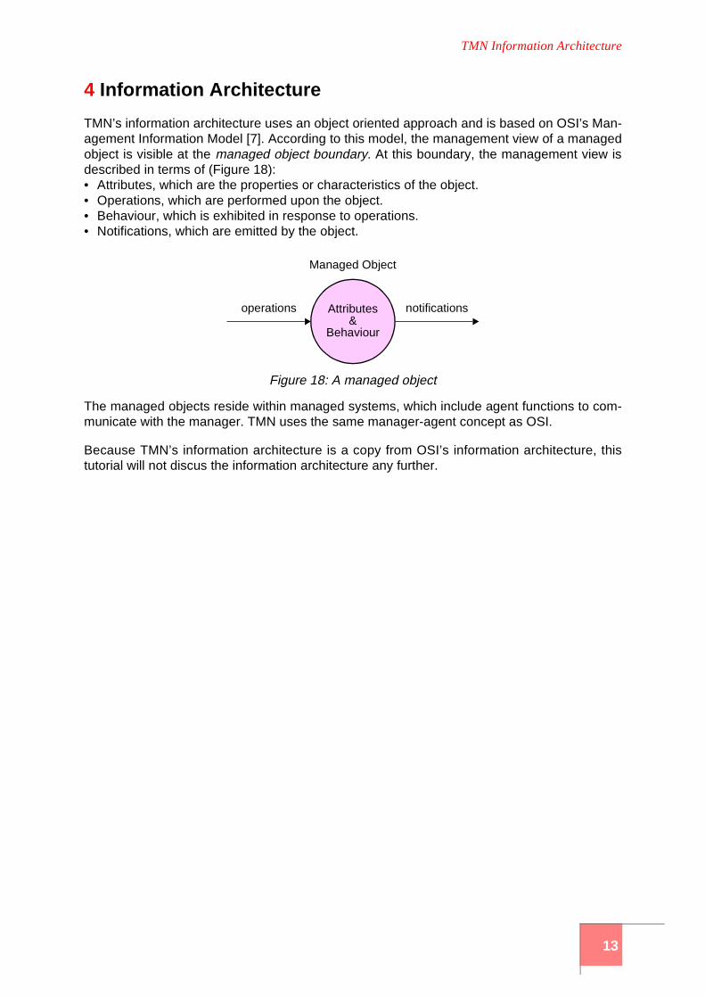
TMN’s information architecture uses an object oriented approach and is based on OSI’s Man-agement Information Model [7]. According to this model, the management view of a managedobject is visible at the managed object boundary. At this boundary, the management view isdescribed in terms of (Figure 18):• Attributes, which are the properties or characteristics of the object.• Operations, which are performed upon the object.• Behaviour, which is exhibited in response to operations.• Notifications, which are emitted by the object.
The managed objects reside within managed systems, which include agent functions to com-municate with the manager. TMN uses the same manager-agent concept as OSI.
Because TMN’s information architecture is a copy from OSI’s information architecture, thistutorial will not discus the information architecture any further.
Figure 18: A managed object
Managed Object
Attributesoperations notifications&
Behaviour
13

TMN Logical Layerer Architecture
5 Logical Layered Architecture
TMN recognizes that, corresponding to human society, a hierarchy of management responsi-bilities exist. Such hierarchies can be described in terms of management layers; the architec-ture that describes this layering is called the Logical Layered Architecture. Over time the con-cept of management layers has become the most important concept of TMN; it appeared asappendix in the 1992 version of M.3010 and moved into the main text of the 1996 version. Theideas behind this architecture were described first in 1989 by BT [10] as part of its Open Net-work Architecture (ONA). BT uses the name structural architecture for this model [11]; thename responsibility model is being used too.
To deal with the complexity of management, the management functionality with its associatedinformation can be decomposed into a number of logical layers. The principle of such layeringis shown in Figure 19. At the border between Layer 1 and 2 the management view of Layer 2is presented to Layer 1; this view is presented in the form of management information that iscontained within the agent at Layer 2. Note that the management view that is presented to layer1 need not unveil all details of layer 2; the agent at layer 2 will only provide those pieces of man-agement information that are necessary at layer 1. The principle of layering can be applied ina recursive fashion; the management view of Layer 3 can be presented to Layer 2 etc.
A usual decomposition of management functionality leads to the following layers of abstraction:• element management layer.• network management layer.• service management layer.• business management layer.These layers, including their function blocks and reference points, are shown in Figure 20.
5.1 Element Management layerThe functions of individual Network Elements are managed by Operations Systems Functions(OSF) in the Element Management layer. This layer deals with vendor specific managementfunctions and hides these functions from the layer above, the Network Management layer.
Examples of functions performed at the Element Management layer are:• detection of equipment errors,• measuring power consumption,• measuring the temperature of equipment,• measuring the resources that are being used, like CPU-time, buffer space, queue length etc.,• logging of statistical data,• updating firmware.
Manager
Agent Manager
Agent
Layer 1
Layer 2
Layer 3
Figure 19: Decomposition of Management Functionality
14

TMN Logical Layerer Architecture
Note that an OSF in the Element Management Layer and a NEF may be implemented withinthe same piece of equipment, or in different pieces of equipment.
5.2 Network Management layerWhereas the responsibility of the Element Management layer is to manage NEFs implementedwithin single pieces of equipment, the responsibility of the Network Management layer is tomanage the functions related to the interaction between multiple pieces of equipment. At net-work management level the internal structure of the network elements is not visible; this impliesthat buffer space within routers, the temperature of switches etc. can not be directly managedat this level.
Examples of functions performed at this layer are:• creation of the complete network view, • creation of dedicated paths through the network to support the QoS demands of end users, • modification of routing tables,• monitoring of link utilization,• optimizing network performance, and• detection of faults.
The OSFs at the Network Management layer use the vendor independent management infor-mation that is provided by the OSFs in the Element Management layer. In this interaction theOSFs at the Network Management layer act in a manager role and the OSFs in the ElementManagement layer in an agent role.
BusinessManagement Layer
ServiceManagement Layer
NetworkManagement Layer
ElementManagement Layer
NetworkElement Layer
x
x
x
q3
q3
q3
q3
Figure 20: TMN-LLA Functional hierarchy
NEF
OSF
OSF
OSF
OSF
15

TMN Logical Layerer Architecture
5.3 Service Management layerThe Service Management layer is concerned with management of those aspects that maydirectly be observed by the users of the telecommunication network. These users may be endusers (customers) but also other service providers (administrations). Service Managementbuilds upon the management information that is provided by the Network Management layer,but does not ‘see’ the internal structure of the network. Routers, switches, links etc. can there-fore not directly be managed at Service Management level.
Examples of functions performed at the Service Management layer are:• Quality of Service management (delay, loss, etc.), • Accounting,• Addition and removal of users,• Address assignment,• Maintenance of group addresses.
The notion of Service Management can be regarded as the most valuable contribution of TMNand other management frameworks, most notably the Internet management framework, maytake advantage of this idea and extend their management frameworks with this notion.
5.4 Examples of Service ManagementService Management may be useful in many cases.
A first case is the example in which two operators exchange management information tomanage their interconnected networks (inter-operator management). For commercial andsecurity reasons each of these operators will try to hide the internal structure of its network fromthe other operator; only those pieces of management information that are absolutely necessarywill be exchanged. An example of such information may be Quality of Service figures.
A second case is the example where an operator who provides end-to-end transport servicesuses the network of another operator to connect its network elements. A typical example is anIP service provider, who uses ATM (or SDH or DWDM) links of other operators to connect itsIP routers. This case is shown in Figure 21. In this figure there are three x-reference points fromthe IP service provider to the ATM service provider. At the side of the ATM service provider, allreference points are connected to the service management layer, since this service providerwill not allow the IP service provider to monitor and modify the internals of its ATM network;only high level information like Quality of Service figures will be made available. For the IP serv-ice provider the ATM link can be seen as a single element in its IP network; this explains thereference point at the element management layer. In case the IP service provider has theoption to choose alternative routes around the ATM link, there will also be a reference point atnetwork management level. Finally the performance of the ATM link may impact the Quality ofService of the entire IP network; in this case there may be also be a reference point at servicemanagement level.
A third case is the example where an operator should exchange management information withcustomers (customer network management). Again the operator will try to hide the internalstructure of its network from the customer, and allow the customer only access to high levelinformation. Possible management interactions may be the provision of QoS figures by theoperator or the modification of the members of a closed user group by the customer.
A fourth case is the example of Value Added Services (VAS). In this case one OSF may beresponsible for management of the VAS and another OSF may be responsible for manage-ment of the telecommunications network that must be traversed to use the service. Both OSFs
16

TMN Logical Layerer Architecture
must be able to communicate with each other. If these OSFs belong to the same TMN (admin-istration), communication is realized over a q reference point. If both OSFs belong to differentTMNs, the x reference point will be used (Figure 22).
ServiceManagement Layer
NetworkManagement Layer
Network ElementLayer
BusinessManagement Layer
x
Provider TMN
ElementManagement Layer
(e.g. ATM Transport provider)Customer TMN
(IP Service provider)
x
x
Figure 21: Example of IP service provider who uses ATM links
OSF
OSF
OSF
OSF
NEFNEF
OSF
OSF
OSF
OSF
ServiceManagement Layer
NetworkManagement Layer
Element
Management Layer
Network ElementLayer
BusinessManagement Layer
qx
Service ProviderValue AddedService Provider
TMN1
TMN2
Figure 22: Example of Value Added Services
NEF
OSF
OSF
OSFOSF
OSF OSF
OSF
OSF
17

TMN Logical Layerer Architecture
5.5 Business Management layerThe Business Management layer is responsible for the management of the whole enterprise.This layer has a broad scope; communications management is just a part of it. Business man-agement can be seen as goal setting, rather than goal achieving. For this reason businessManagement can better be related to strategical and tactical management, instead of opera-tional management, like the other management layers of TMN.
18

Relation with other management approaches
6 Relation with other management approaches
Although TMN recommendation M.3010 does not make any reference to the Internet nor to itsmanagement protocol SNMP, it is still possible to explain the relationship between TMN andSNMP. TMN also includes a number of concepts that may be relevant to the Internet manage-ment community.
There is a strong relationship between TMN and OSI management. TMN’s functional architec-ture, which is defined in terms of function blocks and reference points, can for example beexplained in terms of OSI concepts. Function blocks contain functional components (such as‘Presentation Functions’ or MIBs) and are comparable to OSI protocol entities. Referencepoints are used to interconnect function blocks and are in OSI terminology comparable tounderlying (management information) service providers (Figure 23).
6.1 TMN and Internet managementAn important difference between TMN and Internet management is that the first concentrateson the specification of management architectures and the second on the implementation ofmanagement protocols. As a result, there are only a limited number of TMN products on themarket, whereas there are many commercial as well as public domain Internet managementproducts. In fact, the Internet community did not bother about management architectures untilthey discovered that they could only obtain sufficient support for their new management proto-col if they introduced a modular architecture for SNMPv3. As compared to the rich collection ofarchitectural concepts defined by TMN, the SNMPv3 architecture remains relatively simple.
Integration between TMN and SNMP has been an important research topic and many researchgroups, in particular groups funded by the European RACE programme, addressed this topic.Integration is usually obtained via a Q Adaptor Function (QAF). The QAF translates betweenthe q3 reference point, which is implemented as an OSI management protocol stack (CMIP),and the m reference point, which is implemented as an Internet management (SNMP) protocolstack. The most critical task of the QAF is to translate between TMN’s information model, whichuses the OSI Guidelines for the Definition of Managed Objects (GDMO), and the Internet’sStructure of Management Information (SMI).
As opposed to Internet management, the TMN specifications suggest a conceptual separationbetween the network that is managed (the telecommunication network) and the network thattransfers the management information (the Data Communication Network, DCN). Members ofthe Internet management group took a different approach: they preferred to use the same com-ponents for the network that is managed and the network over which management informationis transferred. The idea to introduce a separate network to transfer management information iscomparable to the idea to introduce a separate network to exchange signalling information. Inthis sense TMN resembles the SS No. 7 network.
Figure 23: Relation between TMN concepts and OSI concepts
protocol entityC
protocol entityB
protocol entityA
service provider Yservice provider X
X Y
TMN:
OSI:
A B C
19

Relation with other management approaches
Probably TMN’s most valuable concept is the Logical Layered Architecture (LLA). This archi-tecture distinguishes between element, network, service and business management. Internetmanagement has traditionally focused on element and network management, but needs toextend in the direction of service management to allow the exchange of management informa-tion between different operators as well as between customers and operator. The question ofhow to extend the Internet management framework with service management is investigatedby research groups within the IRTF.
6.2 TMN and OSI managementInitially there was little collaboration between the management groups of CCITT and ISO/IEC.As a result, the 1988 version of Recommendation M.30 had no ISO/IEC counterpart and ISO/IEC standards had little impact on TMN. After publication of M.30, the collaboration betweenCCITT and ISO/IEC improved, which resulted in the incorporation of many OSI managementideas into TMN. Nowadays work on TMN and OSI management is being performed within theTeleManagement Forum (TMF), which is the successor of the Network Management Forum(NMF).
The most important changes to TMN were:• The ‘manager-agent’ concept, as originally developed by ISO/IEC, was adopted. The current
TMN text contains for instance a statement saying that “The description of the manager/agent concept … is intended to reflect the definitions given in X.701” (the OSI Systems Man-agement Overview).
• ISO/IEC’s ‘Object Oriented’ approach was copied. The current TMN text says: “... the TMNmethodology makes use of the OSI systems management principles and is based on anobject oriented paradigm”.
• The idea of ‘Management Domains’ was included. A number of TMN drafts that were devel-oped during the 1988-1992 study period contained notes saying: “CCITT SG VII and ISOhave a work item on the definition of Management Domains. Resulting material should beused or referenced when available”.
Despite this cooperation between the ITU-T and OSI management groups, fundamental differ-ences in philosophy still exist.
6.3 Differences between TMN and OSI managementA first difference between OSI and TMN management is that OSI has defined a single man-agement architecture whereas TMN defined multiple architectures at different levels of abstrac-tion. In general it may be a good idea to define multiple architectures. This is particularly truein case each architecture elaborates an additional, orthogonal issue. Care should be taken,
Figure 24: Integration between TMN and SNMP
q3
m
SNMPAGENT
TMN ENVIRONMENT
SNMP ENVIRONMENT
QAF
OSF
20

Relation with other management approaches
however, that the relationship between the various architectures remains easy to understand.In the specific example of TMN’s functional and physical architecture, this has been the case.
A second difference between TMN and OSI management is that TMN defines a structure forthe multiple levels of management responsibility that exist in real networks; OSI managementdoes not provide such structure. The TMN structure is known as the ‘Logical Layered Architec-ture’. The advantage of having such a structure, is that understanding and distinguishing thevarious management responsibilities becomes easier.
A third difference between TMN and OSI management is that, as opposed to OSI, TMN sug-gests a conceptual separation between the network that is managed (the telecommunicationnetwork) and the network that transfers the management information (the Data CommunicationNetwork, DCN).
6.4 Separating the management from the telecommunication networkSeparating the management network from the telecommunication network prevents potentialproblems with fault management: even in the case of a failure in the telecommunication net-work, management will still be able to access the failing components. TMN has thus better faultmanagement capabilities than management approaches like OSI and SNMP. Unfortunately,the separate management network requires additional equipment and transmission systems.Costs are thus higher. However, failures can also take place in the management network andtherefore it will be necessary to manage the management network too (meta management).This introduces additional costs.
There is also another reason to introduce a separate network for management. Telecommuni-cation networks, like the one for telephony, provide an isochronous type of service. Such typeof service does not correspond to the asynchronous (packet oriented) type of service that isrequired to transfer management information. A separate management network must thus beintroduced to manage the telephone network. The better fault management capabilities of theseparation are in such case only a secondary consideration.As opposed to TMN, OSI and SNMP are particularly aimed at management of datacommuni-cation networks. The type of service provided by such networks is usually the same as the typeof service required for the exchange of management information. With datacommunication net-works, and thus in case of OSI and SNMP, a serious consideration is needed whether theadvantages of a DCN outweigh its costs.
21

References
7 References
[1] Masahiko Matsushita: “Telecommunication Management Network”, NTT Review, Vol. 3 No. 4, July 1991, page 117 - 122
[2] CCITT Blue Book: “Recommendation M.30, Principles for a Telecommunications Management Network”, Volume IV - Fascicle IV.1, Geneva 1989
[3] CCITT: “Recommendation M.3010, Principles for a Telecommunications Management Network”, Geneva 1992
[4] CCITT: “Recommendation M.3010, Principles for a Telecommunications Management Network”, Geneva 1996
[5] ISO 9595: “Information Processing Systems - Open Systems Interconnection - Common Management Information Service Definition”, Geneva, 1990
[6] ISO 9596: “Information Processing Systems - Open Systems Interconnection - Common Management Information Protocol”, Geneva, 1991
[7] ISO DIS 10165-1: “Information Processing Systems - Open Systems Interconnection - Structure of Management Information - Part 1: Management Information Model”, Geneva, 1993
[8] CCITT COM IV-42-E, Question 23/IV: “Draft Recommendation M.30 - Version R1”, November 1990
[9] CCITT COM IV-61-E, Question 23/IV: “Draft Recommendation M.30 - Version R4”, August 1991[10] Boyd R.T., Brodrick K.J.: “Operational Support Systems for the future Local Network”, BT
Technology Journal, Vol. 7, No. 2, April 1989, page 136-150[11] Milham D.J., Willetts K.J.: “BT’s Communications Management Architecture”, in: Proceedings of
the IFIP TC6/WG 6.6 Symposium on Integrated Network Management, page 109-116, North-Holland, 1989
22