introduction to scaling networks - managementboek.nl€¦ · chapter 1 introduction to scaling...
TRANSCRIPT

CHAPTER 1
Introduction to Scaling Networks
ObjectivesUpon completion of this chapter, you will be able to answer the following questions:
How is the hierarchical network used in small business?
What are the recommendations for design-ing a network that is scalable?
What features in switch hardware are neces-sary to support small- to medium-sized busi-ness network requirements?
What types of routers are available for small- to medium-sized business networks?
What are the basic configuration settings for a Cisco IOS device?
Key TermsThis chapter uses the following key terms. You can find the definitions in the Glossary.
hierarchical network page 3
Cisco Enterprise Architecture page 3
enterprise network page 4
reliability page 5
access layer page 6
distribution layer page 6
core layer page 6
Enterprise Campus page 8
port density page 8
redundancy page 8
Server Farm and Data Center Module
page 8
Services Module page 8
Enterprise Edge page 9
Service Provider Edge page 9
failure domain page 9
multilayer switch page 10
cluster page 11
EtherChannel page 11
Spanning Tree Protocol (STP) page 12
link aggregation page 13
load-balancing page 14
wireless access point (AP) page 15
link-state routing protocol page 15
Open Shortest Path First (OSPF) page 15
Single-Area OSPF page 16
Multiarea OSPF page 16
Enhanced Interior Gateway Routing Protocol
(EIGRP) page 17
distance vector routing protocol page 17

2 Scaling Networks Companion Guide
Protocol Dependent Modules page 17
fixed configuration page 19
modular configuration page 19
stackable configuration page 19
forwarding rates page 22
wire speed page 22
Power over Ethernet (PoE) page 23
application-specific integrated circuit (ASIC)
page 25
branch router page 28
network edge router page 28
service provider router page 29
Cisco IOS page 30
in-band management page 31
out-of-band management page 31
Chapter 1: Introduction to Scaling Networks 3
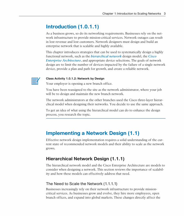
Introduction (1.0.1.1)As a business grows, so do its networking requirements. Businesses rely on the net-work infrastructure to provide mission-critical services. Network outages can result in lost revenue and lost customers. Network designers must design and build an enterprise network that is scalable and highly available.
This chapter introduces strategies that can be used to systematically design a highly functional network, such as the hierarchical network design model, the Cisco
Enterprise Architecture, and appropriate device selections. The goals of network design are to limit the number of devices impacted by the failure of a single network device, provide a plan and path for growth, and create a reliable network.
Class Activity 1.0.1.2: Network by Design
Your employer is opening a new branch office.
You have been reassigned to the site as the network administrator, where your job will be to design and maintain the new branch network.
The network administrators at the other branches used the Cisco three-layer hierar-chical model when designing their networks. You decide to use the same approach.
To get an idea of what using the hierarchical model can do to enhance the design process, you research the topic.
Implementing a Network Design (1.1)Effective network design implementation requires a solid understanding of the cur-rent state of recommended network models and their ability to scale as the network grows.
Hierarchical Network Design (1.1.1)
The hierarchical network model and the Cisco Enterprise Architecture are models to consider when designing a network. This section reviews the importance of scalabil-ity and how these models can effectively address that need.
The Need to Scale the Network (1.1.1.1)
Businesses increasingly rely on their network infrastructure to provide mission-critical services. As businesses grow and evolve, they hire more employees, open branch offices, and expand into global markets. These changes directly affect the

4 Scaling Networks Companion Guide
requirements of a network. A large business environment with many users, locations, and systems is referred to as an enterprise. The network that is used to support the business enterprise is called an enterprise network.
In Figure 1-1, the following steps occur as the network grows from a small company to a global enterprise:
1. The company begins as a small, single-location company.
2. The company increases its number of employees.
3. The company grows to multiple locations in the same city.
4. The enterprise grows to multiple cities.
5. The enterprise hires teleworkers.
6. The enterprise expands to other countries (not all enterprises are international).
7. The enterprise centralizes network management in a Network Operations Center (NOC).
1
72
3
5
4
6
Figure 1-1 Scaling the Network as the Business Grows
An enterprise network must support the exchange of various types of network traf-fic, including data files, email, IP telephony, and video applications for multiple business units. All enterprise networks must
Support critical applications
Support converged network traffic
Chapter 1: Introduction to Scaling Networks 5
Support diverse business needs
Provide centralized administrative control
Enterprise Business Devices (1.1.1.2)
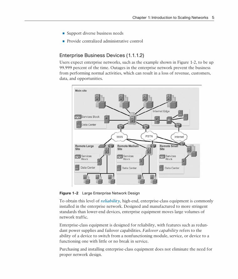
Users expect enterprise networks, such as the example shown in Figure 1-2, to be up 99.999 percent of the time. Outages in the enterprise network prevent the business from performing normal activities, which can result in a loss of revenue, customers, data, and opportunities.
Figure 1-2 Large Enterprise Network Design
To obtain this level of reliability, high-end, enterprise-class equipment is commonly installed in the enterprise network. Designed and manufactured to more stringent standards than lower-end devices, enterprise equipment moves large volumes of network traffic.
Enterprise-class equipment is designed for reliability, with features such as redun-dant power supplies and failover capabilities. Failover capability refers to the ability of a device to switch from a nonfunctioning module, service, or device to a functioning one with little or no break in service.
Purchasing and installing enterprise-class equipment does not eliminate the need for proper network design.
6 Scaling Networks Companion Guide
Hierarchical Network Design (1.1.1.3)
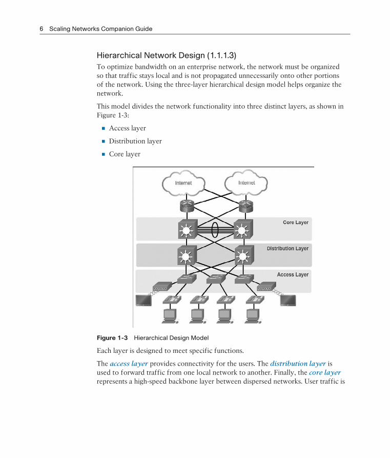
To optimize bandwidth on an enterprise network, the network must be organized so that traffic stays local and is not propagated unnecessarily onto other portions of the network. Using the three-layer hierarchical design model helps organize the network.
This model divides the network functionality into three distinct layers, as shown in Figure 1-3:
Access layer
Distribution layer
Core layer
Figure 1-3 Hierarchical Design Model
Each layer is designed to meet specific functions.
The access layer provides connectivity for the users. The distribution layer is used to forward traffic from one local network to another. Finally, the core layer represents a high-speed backbone layer between dispersed networks. User traffic is
Chapter 1: Introduction to Scaling Networks 7
initiated at the access layer and passes through the other layers if the functionality of those layers is required.
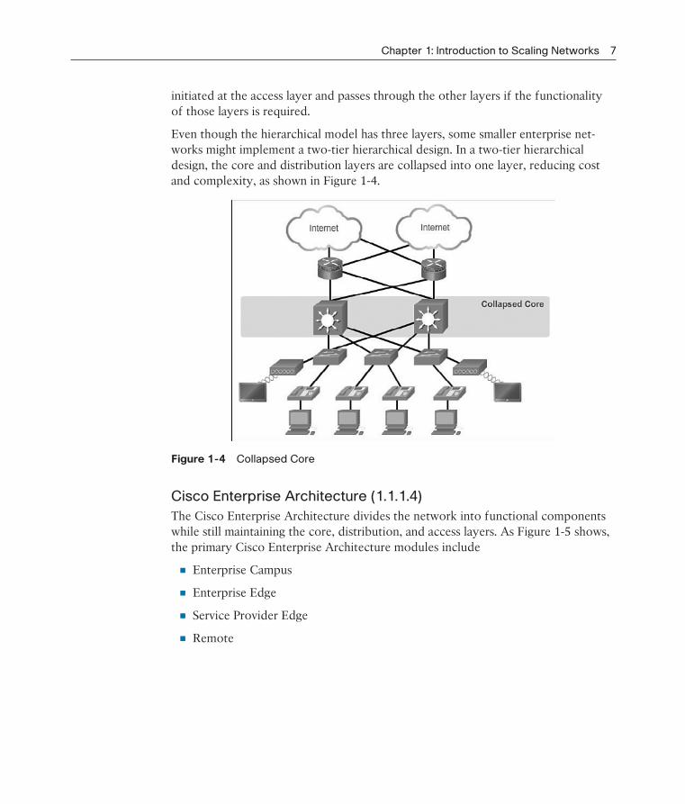
Even though the hierarchical model has three layers, some smaller enterprise net-works might implement a two-tier hierarchical design. In a two-tier hierarchical design, the core and distribution layers are collapsed into one layer, reducing cost and complexity, as shown in Figure 1-4.
Figure 1-4 Collapsed Core
Cisco Enterprise Architecture (1.1.1.4)
The Cisco Enterprise Architecture divides the network into functional components while still maintaining the core, distribution, and access layers. As Figure 1-5 shows, the primary Cisco Enterprise Architecture modules include
Enterprise Campus
Enterprise Edge
Service Provider Edge
Remote
8 Scaling Networks Companion Guide
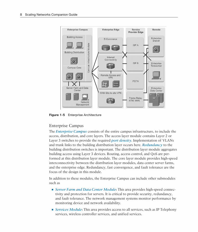
Figure 1-5 Enterprise Architecture
Enterprise CampusThe Enterprise Campus consists of the entire campus infrastructure, to include the access, distribution, and core layers. The access layer module contains Layer 2 or Layer 3 switches to provide the required port density. Implementation of VLANs and trunk links to the building distribution layer occurs here. Redundancy to the building distribution switches is important. The distribution layer module aggregates building access using Layer 3 devices. Routing, access control, and QoS are per-formed at this distribution layer module. The core layer module provides high-speed interconnectivity between the distribution layer modules, data center server farms, and the enterprise edge. Redundancy, fast convergence, and fault tolerance are the focus of the design in this module.
In addition to these modules, the Enterprise Campus can include other submodules such as
Server Farm and Data Center Module: This area provides high-speed connec-tivity and protection for servers. It is critical to provide security, redundancy, and fault tolerance. The network management systems monitor performance by monitoring device and network availability.
Services Module: This area provides access to all services, such as IP Telephony services, wireless controller services, and unified services.
Chapter 1: Introduction to Scaling Networks 9
Enterprise EdgeThe Enterprise Edge consists of the Internet, VPN, and WAN modules connecting the enterprise with the service provider’s network. This module extends the enter-prise services to remote sites and enables the enterprise to use Internet and partner resources. It provides QoS, policy reinforcement, service levels, and security.
Service Provider EdgeThe Service Provider Edge provides Internet, Public Switched Telephone Network (PSTN), and WAN services.
All data that enters or exits the Enterprise Composite Network Model (ECNM) passes through an edge device. This is the point where all packets can be examined and a decision made whether the packet should be allowed on the enterprise net-work. Intrusion detection systems (IDS) and intrusion prevention systems (IPS) can also be configured at the enterprise edge to protect against malicious activity.
Failure Domains (1.1.1.5)
A well-designed network not only controls traffic but also limits the size of failure domains. A failure domain is the area of a network that is impacted when a critical device or network service experiences problems.
The function of the device that initially fails determines the impact of a failure domain. For example, a malfunctioning switch on a network segment normally affects only the hosts on that segment. However, if the router that connects this seg-ment to others fails, the impact is much greater.
The use of redundant links and reliable enterprise-class equipment minimizes the chance of disruption in a network. Smaller failure domains reduce the impact of a failure on company productivity. They also simplify the troubleshooting process, thereby shortening the downtime for all users.
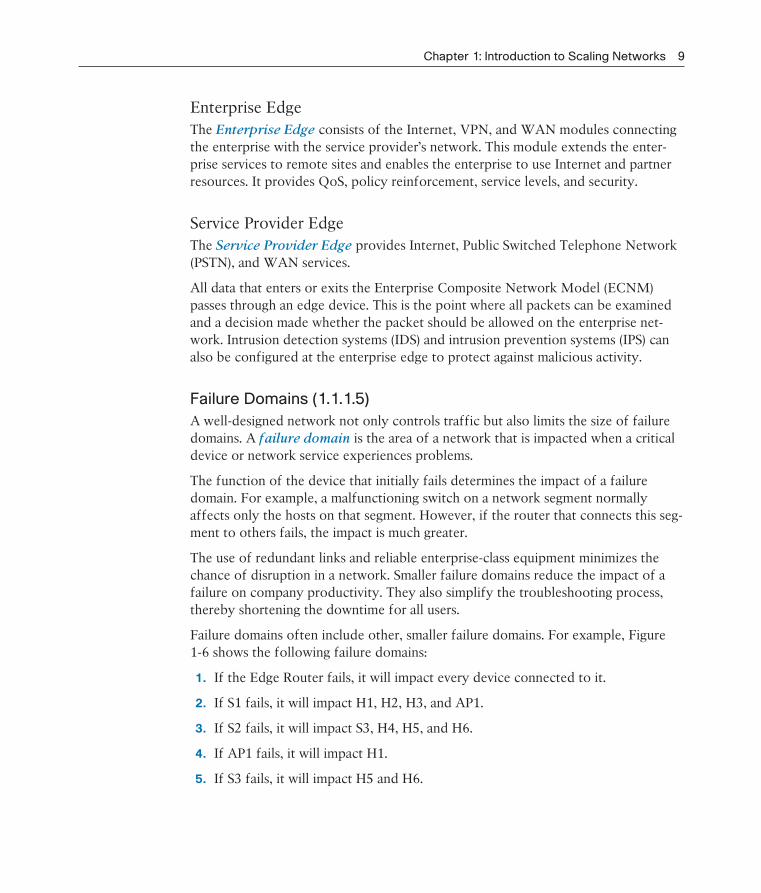
Failure domains often include other, smaller failure domains. For example, Figure 1-6 shows the following failure domains:
1. If the Edge Router fails, it will impact every device connected to it.
2. If S1 fails, it will impact H1, H2, H3, and AP1.
3. If S2 fails, it will impact S3, H4, H5, and H6.
4. If AP1 fails, it will impact H1.
5. If S3 fails, it will impact H5 and H6.

10 Scaling Networks Companion Guide
1
2
3
5
4
Figure 1-6 Failure Domain Examples
Limiting the Size of Failure DomainsBecause a failure at the core layer of a network can have a potentially large impact, the network designer often concentrates on efforts to prevent failures. These efforts can greatly increase the cost of implementing the network. In the hierarchical design model, it is easiest and usually least expensive to control the size of a failure domain in the distribution layer. In the distribution layer, network errors can be contained to a smaller area, thus affecting fewer users. When using Layer 3 devices at the dis-tribution layer, every router functions as a gateway for a limited number of access layer users.
Switch Block DeploymentRouters, or multilayer switches, are usually deployed in pairs, with access layer switches evenly divided between them. This configuration is referred to as a build-ing, or departmental, switch block. Each switch block acts independently of the others. As a result, the failure of a single device does not cause the network to go down. Even the failure of an entire switch block does not affect a significant number of end users.
Activity 1.1.1.6: Identify Cisco Enterprise Architecture Modules
Go to the course online to perform this practice activity.InteractiveGraphic

Chapter 1: Introduction to Scaling Networks 11
Expanding the Network (1.1.2)
A solid network design is not all that is needed for network expansion. This sec-tion reviews the features necessary to ensure that the network scales well as the company grows.
Design for Scalability (1.1.2.1)
To support an enterprise network, the network designer must develop a strategy to enable the network to be available and to scale effectively and easily. Included in a basic network design strategy are the following recommendations:
Use expandable, modular equipment or clustered devices that can be easily upgraded to increase capabilities. Device modules can be added to the existing equipment to support new features and devices without requiring major equip-ment upgrades. Some devices can be integrated in a cluster to act as one device to simplify management and configuration.
Design a hierarchical network to include modules that can be added, upgraded, and modified, as necessary, without affecting the design of the other functional areas of the network. For example, you can create a separate access layer that can be expanded without affecting the distribution and core layers of the cam-pus network.
Create an IPv4 or IPv6 address strategy that is hierarchical. Careful address plan-ning eliminates the need to re-address the network to support additional users and services.
Choose routers or multilayer switches to limit broadcasts and filter other unde-sirable traffic from the network. Use Layer 3 devices to filter and reduce traffic to the network core.
Figure 1-7 shows examples of some more advanced network requirements.
Advanced network design requirements shown in Figure 1-7 include
Implementing redundant links in the network between critical devices and between access layer and core layer devices.
Implementing multiple links between equipment, with either link aggregation (EtherChannel) or equal-cost load balancing, to increase bandwidth. Combining multiple Ethernet links into a single, load-balanced EtherChannel configuration increases available bandwidth. EtherChannel implementations can be used when budget restrictions prohibit purchasing high-speed interfaces and fiber runs.
Implementing wireless connectivity to allow for mobility and expansion.
Using a scalable routing protocol and implementing features within that routing protocol to isolate routing updates and minimize the size of the routing table.

12 Scaling Networks Companion Guide
Figure 1-7 Design for Scalability
Planning for Redundancy (1.1.2.2)
Redundancy is a critical design feature for most company networks.
Implementing RedundancyFor many organizations, the availability of the network is essential to supporting business needs. Redundancy is an important part of network design for preventing disruption of network services by minimizing the possibility of a single point of fail-ure. One method of implementing redundancy is by installing duplicate equipment and providing failover services for critical devices.
Another method of implementing redundancy is using redundant paths, as shown in Figure 1-8.
Redundant paths offer alternate physical paths for data to traverse the network. Redundant paths in a switched network support high availability. However, because of the operation of switches, redundant paths in a switched Ethernet network can cause logical Layer 2 loops. For this reason, Spanning Tree Protocol (STP) is required.

Chapter 1: Introduction to Scaling Networks 13
Figure 1-8 LAN Redundancy
STP allows for the redundancy required for reliability but eliminates the switch-ing loops. It does this by providing a mechanism for disabling redundant paths in a switched network until the path is necessary, such as when failures occur. STP is an open standard protocol, used in a switched environment to create a loop-free logical topology.
More details about LAN redundancy and the operation of STP are covered in Chapter 2, “LAN Redundancy.”
Increasing Bandwidth (1.1.2.3)
Bandwidth demand continues to grow as users increasingly access video content and migrate to IP phones. EtherChannel can quickly add more bandwidth.
Implementing EtherChannelIn hierarchical network design, some links between access and distribution switches might need to process a greater amount of traffic than other links. As traffic from multiple links converges onto a single, outgoing link, it is possible for that link to become a bottleneck. Link aggregation allows an administrator to increase the amount of bandwidth between devices by creating one logical link made up of sev-eral physical links. EtherChannel is a form of link aggregation used in switched net-works, as shown in Figure 1-9.

14 Scaling Networks Companion Guide
Figure 1-9 Advantages of EtherChannel
EtherChannel uses the existing switch ports; therefore, additional costs to upgrade the link to a faster and more expensive connection are not necessary. The Ether-Channel is seen as one logical link using an EtherChannel interface. Most configu-ration tasks are done on the EtherChannel interface, instead of on each individual port, ensuring configuration consistency throughout the links. Finally, the Ether-Channel configuration takes advantage of load balancing between links that are part of the same EtherChannel, and depending on the hardware platform, one or more load-balancing methods can be implemented.
EtherChannel operation and configuration will be covered in more detail in Chapter 3, “LAN Aggregation.”
Expanding the Access Layer (1.1.2.4)
Except in the most secure setting, today’s users expect wireless access to the networks.
Implementing Wireless ConnectivityThe network must be designed to be able to expand network access to individuals and devices, as needed. An increasingly important aspect of extending access layer connectivity is through wireless connectivity. Providing wireless connectivity offers many advantages, such as increased flexibility, reduced costs, and the ability to grow and adapt to changing network and business requirements.
To communicate wirelessly, end devices require a wireless NIC that incorporates a radio transmitter/receiver and the required software driver to make it operational.
Chapter 1: Introduction to Scaling Networks 15
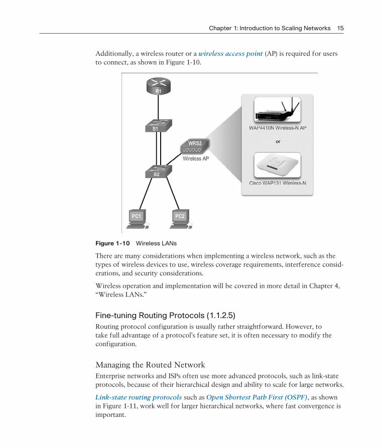
Additionally, a wireless router or a wireless access point (AP) is required for users to connect, as shown in Figure 1-10.
Figure 1-10 Wireless LANs
There are many considerations when implementing a wireless network, such as the types of wireless devices to use, wireless coverage requirements, interference consid-erations, and security considerations.
Wireless operation and implementation will be covered in more detail in Chapter 4, “Wireless LANs.”
Fine-tuning Routing Protocols (1.1.2.5)
Routing protocol configuration is usually rather straightforward. However, to take full advantage of a protocol’s feature set, it is often necessary to modify the configuration.
Managing the Routed NetworkEnterprise networks and ISPs often use more advanced protocols, such as link-state protocols, because of their hierarchical design and ability to scale for large networks.
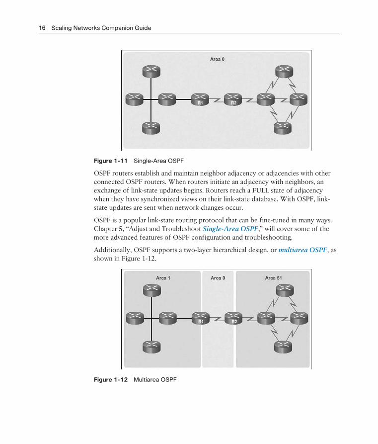
Link-state routing protocols such as Open Shortest Path First (OSPF), as shown in Figure 1-11, work well for larger hierarchical networks, where fast convergence is important.
16 Scaling Networks Companion Guide
Figure 1-11 Single-Area OSPF
OSPF routers establish and maintain neighbor adjacency or adjacencies with other connected OSPF routers. When routers initiate an adjacency with neighbors, an exchange of link-state updates begins. Routers reach a FULL state of adjacency when they have synchronized views on their link-state database. With OSPF, link-state updates are sent when network changes occur.
OSPF is a popular link-state routing protocol that can be fine-tuned in many ways. Chapter 5, “Adjust and Troubleshoot Single-Area OSPF,” will cover some of the more advanced features of OSPF configuration and troubleshooting.
Additionally, OSPF supports a two-layer hierarchical design, or multiarea OSPF, as shown in Figure 1-12.
Figure 1-12 Multiarea OSPF
Chapter 1: Introduction to Scaling Networks 17
All OSPF networks begin with Area 0, also called the backbone area. As the network is expanded, other nonbackbone areas can be created. All nonbackbone areas must directly connect to area 0. Chapter 6, “Multiarea OSPF,” introduces the benefits, operation, and configuration of multiarea OSPF.
Another popular routing protocol for larger networks is Enhanced Interior Gate-
way Routing Protocol (EIGRP). Cisco developed EIGRP as a proprietary distance
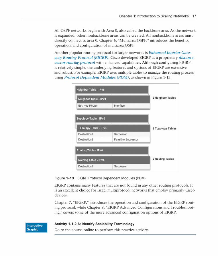
vector routing protocol with enhanced capabilities. Although configuring EIGRP is relatively simple, the underlying features and options of EIGRP are extensive and robust. For example, EIGRP uses multiple tables to manage the routing process using Protocol Dependent Modules (PDM), as shown in Figure 1-13.
Figure 1-13 EIGRP Protocol Dependent Modules (PDM)
EIGRP contains many features that are not found in any other routing protocols. It is an excellent choice for large, multiprotocol networks that employ primarily Cisco devices.
Chapter 7, “EIGRP,” introduces the operation and configuration of the EIGRP rout-ing protocol, while Chapter 8, “EIGRP Advanced Configurations and Troubleshoot-ing,” covers some of the more advanced configuration options of EIGRP.
Activity 1.1.2.6: Identify Scalability Terminology
Go to the course online to perform this practice activity.InteractiveGraphic

18 Scaling Networks Companion Guide
Selecting Network Devices (1.2)A basic understanding of switch and router hardware is essential to implementing network designs that scale.
Switch Hardware (1.2.1)
Cisco switches address the needs at the access, distribution, and core layers. Many models scale well with the network as it grows.
Switch Platforms (1.2.1.1)
When designing a network, it is important to select the proper hardware to meet current network requirements, as well as to allow for network growth. Within an enterprise network, both switches and routers play a critical role in network communication.
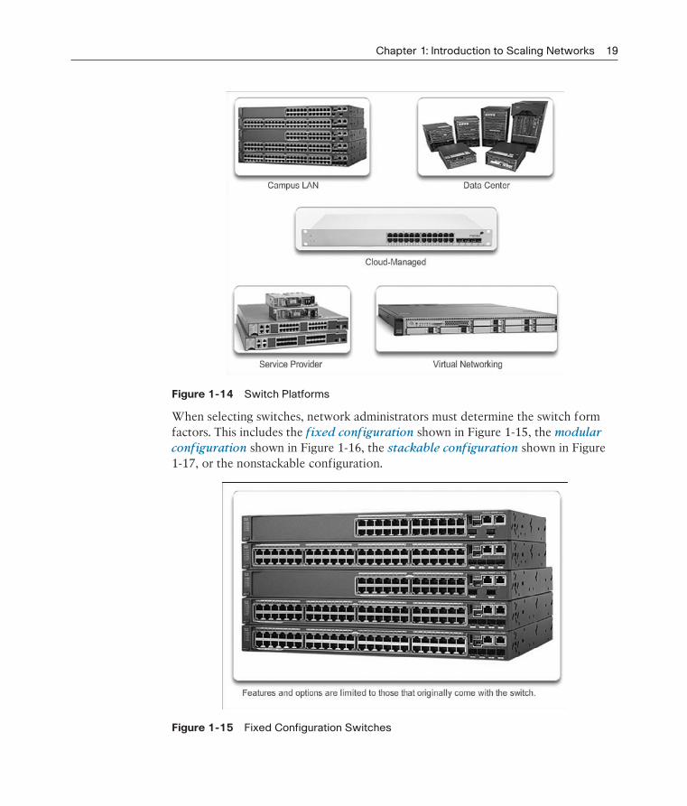
There are five categories of switches for enterprise networks, as shown in Figure 1-14:
Campus LAN Switches: To scale network performance in an enterprise LAN, there are core, distribution, access, and compact switches. These switch plat-forms vary from fanless switches with eight fixed ports to 13-blade switches supporting hundreds of ports. Campus LAN switch platforms include the Cisco 2960, 3560, 3750, 3850, 4500, 6500, and 6800 Series.
Cloud-Managed Switches: The Cisco Meraki cloud-managed access switches enable virtual stacking of switches. They monitor and configure thousands of switch ports over the web, without the intervention of onsite IT staff.
Data Center Switches: A data center should be built based on switches that pro-mote infrastructure scalability, operational continuity, and transport flexibility. The data center switch platforms include the Cisco Nexus Series switches and the Cisco Catalyst 6500 Series switches.
Service Provider Switches: Service provider switches fall under two categories: aggregation switches and Ethernet access switches. Aggregation switches are carrier-grade Ethernet switches that aggregate traffic at the edge of a network. Service provider Ethernet access switches feature application intelligence, uni-fied services, virtualization, integrated security, and simplified management.
Virtual Networking: Networks are becoming increasingly virtualized. Cisco Nexus virtual networking switch platforms provide secure multitenant services by adding virtualization intelligence technology to the data center network.
Chapter 1: Introduction to Scaling Networks 19
Figure 1-14 Switch Platforms
When selecting switches, network administrators must determine the switch form factors. This includes the fixed configuration shown in Figure 1-15, the modular
configuration shown in Figure 1-16, the stackable configuration shown in Figure 1-17, or the nonstackable configuration.
Figure 1-15 Fixed Configuration Switches

20 Scaling Networks Companion Guide
Figure 1-16 Modular Configuration Switches
Figure 1-17 Stackable Configuration Switches
The height of the switch, which is expressed in the number of rack units, is also important for switches that are mounted in a rack. For example, the fixed configura-tion switches shown in Figure 1-15 are all one rack unit (1U) high.
In addition to these considerations, the following list highlights other common busi-ness considerations when selecting switch equipment:

Chapter 1: Introduction to Scaling Networks 21
Cost: The cost of a switch will depend on the number and speed of the inter-faces, supported features, and expansion capability.
Port Density: Network switches must support the appropriate number of devices on the network.
Power: It is now common to power access points, IP phones, and even compact switches using Power over Ethernet (PoE). In addition to PoE considerations, some chassis-based switches support redundant power supplies.
Reliability: The switch should provide continuous access to the network.
Port Speed: The speed of the network connection is of primary concern to end users.
Frame Buffers: The ability of the switch to store frames is important in a net-work where there might be congested ports to servers or other areas of the network.
Scalability: The number of users on a network typically grows over time; there-fore, the switch should provide the opportunity for growth.
Port Density (1.2.1.2)
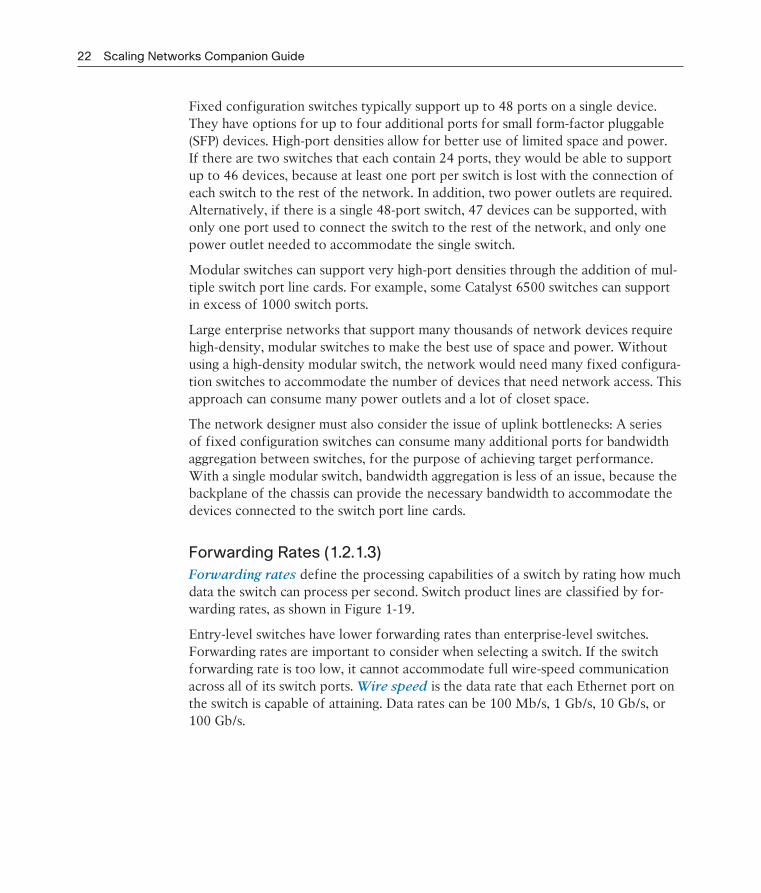
The port density of a switch refers to the number of ports available on a single switch. Figure 1-18 shows the port density of three different switches.
Figure 1-18 Port Densities
22 Scaling Networks Companion Guide
Fixed configuration switches typically support up to 48 ports on a single device. They have options for up to four additional ports for small form-factor pluggable (SFP) devices. High-port densities allow for better use of limited space and power. If there are two switches that each contain 24 ports, they would be able to support up to 46 devices, because at least one port per switch is lost with the connection of each switch to the rest of the network. In addition, two power outlets are required. Alternatively, if there is a single 48-port switch, 47 devices can be supported, with only one port used to connect the switch to the rest of the network, and only one power outlet needed to accommodate the single switch.
Modular switches can support very high-port densities through the addition of mul-tiple switch port line cards. For example, some Catalyst 6500 switches can support in excess of 1000 switch ports.
Large enterprise networks that support many thousands of network devices require high-density, modular switches to make the best use of space and power. Without using a high-density modular switch, the network would need many fixed configura-tion switches to accommodate the number of devices that need network access. This approach can consume many power outlets and a lot of closet space.
The network designer must also consider the issue of uplink bottlenecks: A series of fixed configuration switches can consume many additional ports for bandwidth aggregation between switches, for the purpose of achieving target performance. With a single modular switch, bandwidth aggregation is less of an issue, because the backplane of the chassis can provide the necessary bandwidth to accommodate the devices connected to the switch port line cards.
Forwarding Rates (1.2.1.3)
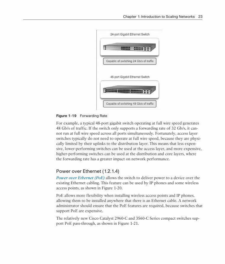
Forwarding rates define the processing capabilities of a switch by rating how much data the switch can process per second. Switch product lines are classified by for-warding rates, as shown in Figure 1-19.
Entry-level switches have lower forwarding rates than enterprise-level switches. Forwarding rates are important to consider when selecting a switch. If the switch forwarding rate is too low, it cannot accommodate full wire-speed communication across all of its switch ports. Wire speed is the data rate that each Ethernet port on the switch is capable of attaining. Data rates can be 100 Mb/s, 1 Gb/s, 10 Gb/s, or 100 Gb/s.
Chapter 1: Introduction to Scaling Networks 23
Figure 1-19 Forwarding Rate
For example, a typical 48-port gigabit switch operating at full wire speed generates 48 Gb/s of traffic. If the switch only supports a forwarding rate of 32 Gb/s, it can-not run at full wire speed across all ports simultaneously. Fortunately, access layer switches typically do not need to operate at full wire speed, because they are physi-cally limited by their uplinks to the distribution layer. This means that less expen-sive, lower-performing switches can be used at the access layer, and more expensive, higher-performing switches can be used at the distribution and core layers, where the forwarding rate has a greater impact on network performance.
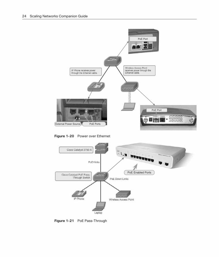
Power over Ethernet (1.2.1.4)
Power over Ethernet (PoE) allows the switch to deliver power to a device over the existing Ethernet cabling. This feature can be used by IP phones and some wireless access points, as shown in Figure 1-20.
PoE allows more flexibility when installing wireless access points and IP phones, allowing them to be installed anywhere that there is an Ethernet cable. A network administrator should ensure that the PoE features are required, because switches that support PoE are expensive.
The relatively new Cisco Catalyst 2960-C and 3560-C Series compact switches sup-port PoE pass-through, as shown in Figure 1-21.
24 Scaling Networks Companion Guide
PoE Port
PoE Port
External Power Source PoE Ports
Figure 1-20 Power over Ethernet
PoE Enabled Ports
Figure 1-21 PoE Pass-Through

Chapter 1: Introduction to Scaling Networks 25
PoE pass-through allows a network administrator to power PoE devices connected to the switch, as well as the switch itself, by drawing power from certain upstream switches.
Multilayer Switching (1.2.1.5)
Multilayer switches are typically deployed in the core and distribution layers of an organization’s switched network. Multilayer switches are characterized by their abil-ity to build a routing table, support a few routing protocols, and forward IP packets at a rate close to that of Layer 2 forwarding. Multilayer switches often support spe-cialized hardware, such as application-specific integrated circuits (ASIC). ASICs, along with dedicated software data structures, can streamline the forwarding of IP packets independent of the CPU.
There is a trend in networking toward a pure Layer 3 switched environment. When switches were first used in networks, none of them supported routing; now, almost all switches support routing. It is likely that soon all switches will incorporate a route processor because the cost of doing so is decreasing relative to other constraints. Eventually the term multilayer switch will be redundant.
As shown in Figure 1-22, the Catalyst 2960 switches illustrate the migration to a pure Layer 3 environment.
Figure 1-22 Cisco Catalyst 2960 Series Switches

26 Scaling Networks Companion Guide
With IOS versions prior to 15.x, these switches supported only one active switched virtual interface (SVI). The Catalyst 2960 also supports multiple active SVIs. This means that the switch can be remotely accessed through multiple IP addresses on distinct networks.
Activity 1.2.1.6: Selecting Switch Hardware
Go to the course online to perform this practice activity.
Packet Tracer Activity 1.2.1.7: Comparing 2960 and 3560 Switches
In this activity, you will use various commands to examine three different switch-ing topologies and compare the similarities and differences between the 2960 and 3560 switches. You will also compare the routing table of a 1941 router with a 3560 switch.
Lab 1.2.1.8: Selecting Switching Hardware
In this lab, you will complete the following objectives:
Part 1: Explore Cisco Switch Products
Part 2: Select an Access Layer Switch
Part 3: Select a Distribution/Core Layer Switch
Router Hardware (1.2.2)
Like switches, routers can play a role in the access, distribution, and core layers of the network. In many small networks like branch offices and a teleworker’s home network, all three layers are implemented within a router.
Router Requirements (1.2.2.1)
In the distribution layer of an enterprise network, routing is required. Without the routing process, packets cannot leave the local network.
Routers play a critical role in networking by interconnecting multiple sites within an enterprise network, providing redundant paths, and connecting ISPs on the Internet. Routers can also act as a translator between different media types and protocols. For example, a router can accept packets from an Ethernet network and reencapsulate them for transport over a serial network.
InteractiveGraphic
Packet Tracer Activity

Chapter 1: Introduction to Scaling Networks 27
Routers use the network portion of the destination IP address to route packets to the proper destination. They select an alternate path if a link goes down or traffic is congested. All hosts on a local network specify the IP address of the local router interface in their IP configuration. This router interface is the default gateway.
Routers also serve the following beneficial functions, as shown in Figure 1-23:
Provide broadcast containment
Connect remote locations
Group users logically by application or department
Provide enhanced security
Routers limit broadcasts to the local network. Routers can be configured with accesscontrol lists to filter unwanted traffic.
Routers can be used to interconnectgeographically separated locations.
Routers logically group users who requireaccess to the same resources.
Figure 1-23 Router Functions
With the enterprise and the ISP, the ability to route efficiently and recover from network link failures is critical to delivering packets to their destination.
28 Scaling Networks Companion Guide
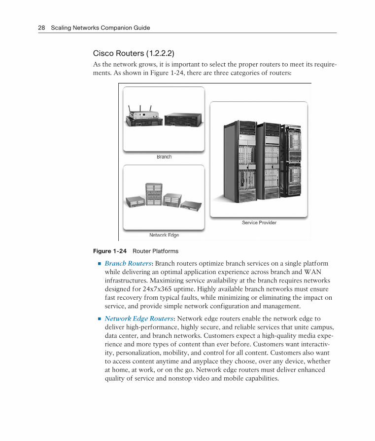
Cisco Routers (1.2.2.2)
As the network grows, it is important to select the proper routers to meet its require-ments. As shown in Figure 1-24, there are three categories of routers:
Figure 1-24 Router Platforms
Branch Routers: Branch routers optimize branch services on a single platform while delivering an optimal application experience across branch and WAN infrastructures. Maximizing service availability at the branch requires networks designed for 24x7x365 uptime. Highly available branch networks must ensure fast recovery from typical faults, while minimizing or eliminating the impact on service, and provide simple network configuration and management.
Network Edge Routers: Network edge routers enable the network edge to deliver high-performance, highly secure, and reliable services that unite campus, data center, and branch networks. Customers expect a high-quality media expe-rience and more types of content than ever before. Customers want interactiv-ity, personalization, mobility, and control for all content. Customers also want to access content anytime and anyplace they choose, over any device, whether at home, at work, or on the go. Network edge routers must deliver enhanced quality of service and nonstop video and mobile capabilities.
Chapter 1: Introduction to Scaling Networks 29
Service Provider Routers: Service provider routers differentiate the service portfolio and increase revenues by delivering end-to-end scalable solutions and subscriber-aware services. Operators must optimize operations, reduce expenses, and improve scalability and flexibility to deliver next-generation Internet experi-ences across all devices and locations. These systems are designed to simplify and enhance the operation and deployment of service-delivery networks.
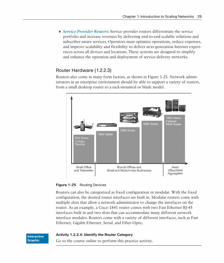
Router Hardware (1.2.2.3)
Routers also come in many form factors, as shown in Figure 1-25. Network admin-istrators in an enterprise environment should be able to support a variety of routers, from a small desktop router to a rack-mounted or blade model.
Figure 1-25 Routing Devices
Routers can also be categorized as fixed configuration or modular. With the fixed configuration, the desired router interfaces are built in. Modular routers come with multiple slots that allow a network administrator to change the interfaces on the router. As an example, a Cisco 1841 router comes with two Fast Ethernet RJ-45 interfaces built in and two slots that can accommodate many different network interface modules. Routers come with a variety of different interfaces, such as Fast Ethernet, Gigabit Ethernet, Serial, and Fiber-Optic.
Activity 1.2.2.4: Identify the Router Category
Go to the course online to perform this practice activity.InteractiveGraphic

30 Scaling Networks Companion Guide
Managing Devices (1.2.3)
Routers and switches all come with Cisco IOS Software. Network administrators are responsible for managing these devices. This includes initial configuration, verifica-tion, and troubleshooting tasks as well as maintaining up-to-date images and backing up the configuration files.
Managing IOS Files and Licensing (1.2.3.1)
With such a wide selection of network devices to choose from in the Cisco prod-uct line, an organization can carefully determine the ideal combination to meet the needs of the employees and the customers.
When selecting or upgrading a Cisco IOS device, it is important to choose the proper IOS image with the correct feature set and version. IOS refers to the package of routing, switching, security, and other internetworking technologies integrated into a single multitasking operating system. When a new device is shipped, it comes preinstalled with the software image and the corresponding permanent licenses for the customer-specified packages and features.
For routers, beginning with Cisco IOS Software Release 15.0, Cisco modified the process to enable new technologies within the IOS feature sets, as shown in Figure 1-26.
Figure 1-26 Cisco IOS Software 15 Release Family
Chapter 9, “IOS Images and Licensing,” covers more information on managing and maintaining the Cisco IOS licenses.
In-Band Versus Out-of-Band Management (1.2.3.2)
Regardless of the Cisco IOS network device being implemented, there are two meth-ods for connecting a PC to that network device for configuration and monitoring

Chapter 1: Introduction to Scaling Networks 31
tasks. These methods include out-of-band and in-band management, as shown in Figure 1-27.
Figure 1-27 In-Band Versus Out-of-Band Configuration Options
Out-of-band management is used for initial configuration or when a network con-nection is unavailable. Configuration using out-of-band management requires
Direct connection to console or AUX port
Terminal emulation client
In-band management is used to monitor and make configuration changes to a net-work device over a network connection. Configuration using in-band management requires
At least one network interface on the device to be connected and operational
Telnet, SSH, or HTTP to access a Cisco device
Basic Router CLI Commands (1.2.3.3)
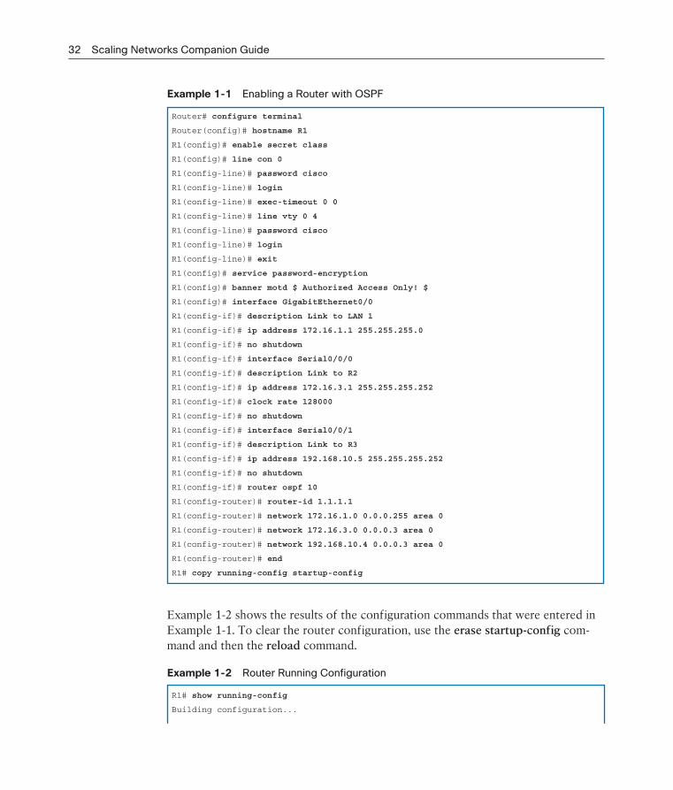
A basic router configuration includes the host name for identification, passwords for security, assignment of IP addresses to interfaces for connectivity, and basic routing. Assuming that the physical interfaces are connected to the network, Example 1-1 shows the commands entered to enable a router with OSPF. Verify and save con-figuration changes using the copy running-config startup-config command.
32 Scaling Networks Companion Guide
Example 1-1 Enabling a Router with OSPF
Router# configure terminal
Router(config)# hostname R1
R1(config)# enable secret class
R1(config)# line con 0
R1(config-line)# password cisco
R1(config-line)# login
R1(config-line)# exec-timeout 0 0
R1(config-line)# line vty 0 4
R1(config-line)# password cisco
R1(config-line)# login
R1(config-line)# exit
R1(config)# service password-encryption
R1(config)# banner motd $ Authorized Access Only! $
R1(config)# interface GigabitEthernet0/0
R1(config-if)# description Link to LAN 1
R1(config-if)# ip address 172.16.1.1 255.255.255.0
R1(config-if)# no shutdown
R1(config-if)# interface Serial0/0/0
R1(config-if)# description Link to R2
R1(config-if)# ip address 172.16.3.1 255.255.255.252
R1(config-if)# clock rate 128000
R1(config-if)# no shutdown
R1(config-if)# interface Serial0/0/1
R1(config-if)# description Link to R3
R1(config-if)# ip address 192.168.10.5 255.255.255.252
R1(config-if)# no shutdown
R1(config-if)# router ospf 10
R1(config-router)# router-id 1.1.1.1
R1(config-router)# network 172.16.1.0 0.0.0.255 area 0
R1(config-router)# network 172.16.3.0 0.0.0.3 area 0
R1(config-router)# network 192.168.10.4 0.0.0.3 area 0
R1(config-router)# end
R1# copy running-config startup-config
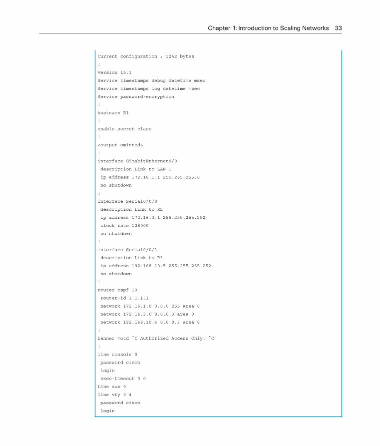
Example 1-2 shows the results of the configuration commands that were entered in Example 1-1. To clear the router configuration, use the erase startup-config com-mand and then the reload command.
Example 1-2 Router Running Configuration
R1# show running-config
Building configuration...
Chapter 1: Introduction to Scaling Networks 33
Current configuration : 1242 bytes
!
Version 15.1
Service timestamps debug datetime msec
Service timestamps log datetime msec
Service password-encryption
!
hostname R1
!
enable secret class
!
<output omitted>
!
interface GigabitEthernet0/0
description Link to LAN 1
ip address 172.16.1.1 255.255.255.0
no shutdown
!
interface Serial0/0/0
description Link to R2
ip address 172.16.3.1 255.255.255.252
clock rate 128000
no shutdown
!
interface Serial0/0/1
description Link to R3
ip address 192.168.10.5 255.255.255.252
no shutdown
!
router ospf 10
router-id 1.1.1.1
network 172.16.1.0 0.0.0.255 area 0
network 172.16.3.0 0.0.0.3 area 0
network 192.168.10.4 0.0.0.3 area 0
!
banner motd ^C Authorized Access Only! ^C
!
line console 0
password cisco
login
exec-timeout 0 0
Line aux 0
line vty 0 4
password cisco
login

34 Scaling Networks Companion Guide
Basic Router show Commands (1.2.3.4)
Here are some of the most commonly used IOS commands to display and verify the operational status of the router and related network functionality. These commands are divided into several categories.
The following show commands are related to routing:
show ip protocols: As shown in Example 1-3, this command displays informa-tion about the routing protocols configured. If OSPF is configured, this includes the OSPF process ID, the router ID, networks the router is advertising, the neighbors the router is receiving updates from, and the default administrative distance, which is 110 for OSPF.
Example 1-3 show ip protocols Command
R1# show ip protocols
Routing Protocol is "ospf 10"
Outgoing update filter list for all interfaces is not set
Incoming update filter list for all interfaces is not set
Router ID 1.1.1.1
Number of areas in this router is 1. 1 normal 0 stub 0 nssa
Maximum path: 4
Routing for Networks:
172.16.1.0 0.0.0.255 area 0
172.16.3.0 0.0.0.3 area 0
192.168.10.4 0.0.0.3 area 0
Passive Interface(s):
GigabitEthernet0/0
Routing Information Sources:
Gateway Distance Last Update
1.1.1.1 110 00:11:48
2.2.2.2 110 00:11:50
3.3.3.3 110 00:11:50
Distance: (default is 110)
show ip route: As shown in Example 1-4, this command displays routing table information, including routing codes, known networks, administrative distance and metrics, how routes were learned, next hop, static routes, and default routes.

Chapter 1: Introduction to Scaling Networks 35
Example 1-4 show ip route Command
R1# show ip route
Codes: L - local, C - connected, S - static, R - RIP, M - mobile, B - BGP
D - EIGRP, EX - EIGRP external, O - OSPF, IA - OSPF inter area
N1 - OSPF NSSA external type 1, N2 - OSPF NSSA external type 2
E1 - OSPF external type 1, E2 - OSPF external type 2, E - EGP
i - IS-IS, L1 - IS-IS level-1, L2 - IS-IS level-2, ia - IS-IS inter area
* - candidate default, U - per-user static route, o - ODR
P - periodic downloaded static route
Gateway of last resort is not set
172.16.0.0/16 is variably subnetted, 5 subnets, 3 masks
C 172.16.1.0/24 is directly connected, GigabitEthernet0/0
L 172.16.1.1/32 is directly connected, GigabitEthernet0/0
O 172.16.2.0/24 [110/65] via 172.16.3.2, 01:43:03, Serial0/0/0
C 172.16.3.0/30 is directly connected, Serial0/0/0
L 172.16.3.1/32 is directly connected, Serial0/0/0
O 192.168.1.0/24 [110/65] via 192.168.10.6, 01:43:03, Serial0/0/1
192.168.10.0/24 is variably subnetted, 3 subnets, 2 masks
C 192.168.10.4/30 is directly connected, Serial0/0/1
L 192.168.10.5/32 is directly connected, Serial0/0/1
O 192.168.10.8/30 [110/128] via 172.16.3.2, 01:43:03, Serial0/0/0
[110/128] via 192.168.10.6, 01:43:03, Serial0/0/1
show ip ospf neighbor: As shown in Example 1-5, this command displays infor-mation about OSPF neighbors that have been learned, including the Router ID of the neighbor, the priority, the state (Full = adjacency has been formed), the IP address, and the local interface that learned of the neighbor.
Example 1-5 show ip ospf neighbor Command
R1# show ip ospf neighbor
Neighbor ID Pri State Dead Time Address Interface
2.2.2.2 0 FULL/ - 00:00:34 172.16.3.2 Serial0/0/0
3.3.3.3 0 FULL/ - 00:00:34 192.168.10.6 Serial0/0/1
The following show commands are related to interfaces:
show interfaces: As shown in Example 1-6, this command displays interfaces with line (protocol) status, bandwidth, delay, reliability, encapsulation, duplex,
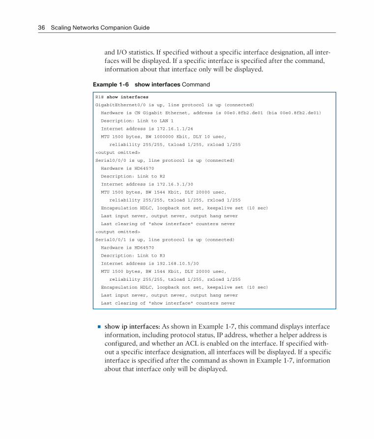
36 Scaling Networks Companion Guide
and I/O statistics. If specified without a specific interface designation, all inter-faces will be displayed. If a specific interface is specified after the command, information about that interface only will be displayed.
Example 1-6 show interfaces Command
R1# show interfaces
GigabitEthernet0/0 is up, line protocol is up (connected)
Hardware is CN Gigabit Ethernet, address is 00e0.8fb2.de01 (bia 00e0.8fb2.de01)
Description: Link to LAN 1
Internet address is 172.16.1.1/24
MTU 1500 bytes, BW 1000000 Kbit, DLY 10 usec,
reliability 255/255, txload 1/255, rxload 1/255
<output omitted>
Serial0/0/0 is up, line protocol is up (connected)
Hardware is HD64570
Description: Link to R2
Internet address is 172.16.3.1/30
MTU 1500 bytes, BW 1544 Kbit, DLY 20000 usec,
reliability 255/255, txload 1/255, rxload 1/255
Encapsulation HDLC, loopback not set, keepalive set (10 sec)
Last input never, output never, output hang never
Last clearing of "show interface" counters never
<output omitted>
Serial0/0/1 is up, line protocol is up (connected)
Hardware is HD64570
Description: Link to R3
Internet address is 192.168.10.5/30
MTU 1500 bytes, BW 1544 Kbit, DLY 20000 usec,
reliability 255/255, txload 1/255, rxload 1/255
Encapsulation HDLC, loopback not set, keepalive set (10 sec)
Last input never, output never, output hang never
Last clearing of "show interface" counters never
show ip interfaces: As shown in Example 1-7, this command displays interface information, including protocol status, IP address, whether a helper address is configured, and whether an ACL is enabled on the interface. If specified with-out a specific interface designation, all interfaces will be displayed. If a specific interface is specified after the command as shown in Example 1-7, information about that interface only will be displayed.
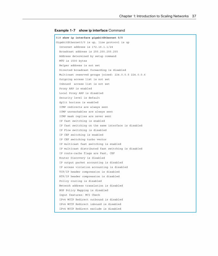
Chapter 1: Introduction to Scaling Networks 37
Example 1-7 show ip interface Command
R1# show ip interface gigabitEthernet 0/0
GigabitEthernet0/0 is up, line protocol is up
Internet address is 172.16.1.1/24
Broadcast address is 255.255.255.255
Address determined by setup command
MTU is 1500 bytes
Helper address is not set
Directed broadcast forwarding is disabled
Multicast reserved groups joined: 224.0.0.5 224.0.0.6
Outgoing access list is not set
Inbound access list is not set
Proxy ARP is enabled
Local Proxy ARP is disabled
Security level is default
Split horizon is enabled
ICMP redirects are always sent
ICMP unreachables are always sent
ICMP mask replies are never sent
IP fast switching is enabled
IP fast switching on the same interface is disabled
IP Flow switching is disabled
IP CEF switching is enabled
IP CEF switching turbo vector
IP multicast fast switching is enabled
IP multicast distributed fast switching is disabled
IP route-cache flags are Fast, CEF
Router Discovery is disabled
IP output packet accounting is disabled
IP access violation accounting is disabled
TCP/IP header compression is disabled
RTP/IP header compression is disabled
Policy routing is disabled
Network address translation is disabled
BGP Policy Mapping is disabled
Input features: MCI Check
IPv4 WCCP Redirect outbound is disabled
IPv4 WCCP Redirect inbound is disabled
IPv4 WCCP Redirect exclude is disabled

38 Scaling Networks Companion Guide
show ip interface brief: As shown in Example 1-8, this command displays all interfaces with IP addressing information and interface and line protocol status.
Example 1-8 show ip interface brief Command
R1# show ip interface brief
Interface IP-Address OK? Method Status Protocol
GigabitEthernet0/0 172.16.1.1 YES manual up up
GigabitEthernet0/1 unassigned YES unset administratively down down
Serial0/0/0 172.16.3.1 YES manual up up
Serial0/0/1 192.168.10.5 YES manual up up
Vlan1 unassigned YES unset administratively down down
show protocols: As shown in Example 1-9, this command displays information about the routed protocol that is enabled and the protocol status of interfaces.
Example 1-9 show protocols Command
R1# show protocols
Global values:
Internet Protocol routing is enabled
GigabitEthernet0/0 is up, line protocol is up
Internet address is 172.16.1.1/24
GigabitEthernet0/1 is administratively down, line protocol is down
Serial0/0/0 is up, line protocol is up
Internet address is 172.16.3.1/30
Serial0/0/1 is up, line protocol is up
Internet address is 192.168.10.5/30
Vlan1 is administratively down, line protocol is down
Other connectivity-related commands include the show cdp neighbors command shown in Example 1-10.
Example 1-10 show cdp neighbors Command
R1# show cdp neighbors
Capability Codes: R - Router, T - Trans Bridge, B - Source Route Bridge
S - Switch, H - Host, I - IGMP, r - Repeater, P - Phone
Device ID Local Intrfce Holdtme Capability Platform Port ID
S1 Gig 0/0 126 S 2960 Gig 1/1
R2 Ser 0/0/0 136 R C1900 Ser 0/0/0
R3 Ser 0/0/1 133 R C1900 Ser 0/0/0

Chapter 1: Introduction to Scaling Networks 39
This command displays information on directly connected devices, including Device ID, local interface that the device is connected to, capability (R = router, S = switch), platform, and Port ID of the remote device. The details option includes IP address-ing information and the IOS version.
Basic Switch CLI Commands (1.2.3.5)
Basic switch configuration includes the host name for identification, passwords for security, and assignment of IP addresses for connectivity. In-band access requires the switch to have an IP address. Example 1-11 shows the commands entered to enable a switch.
Example 1-11 Enable a Switch with a Basic Configuration
Switch# enable
Switch# configure terminal
Switch(config)# hostname S1
S1(config)# enable secret class
S1(config)# line con 0
S1(config-line)# password cisco
S1(config-line)# login
S1(config-line)# line vty 0 4
S1(config-line)# password cisco
S1(config-line)# login
S1(config-line)# service password-encryption
S1(config)# banner motd $ Authorized Access Only! $
S1(config)# interface vlan 1
S1(config-if)# ip address 192.168.1.5 255.255.255.0
S1(config-if)# no shutdown
S1(config-if)# ip default-gateway 192.168.1.1
S1(config)# interface fa0/2
S1(config-if)# switchport mode access
S1(config-if)# switchport port-security
S1(config-if)# end
S1# copy running-config startup-config
Example 1-12 shows the results of the configuration commands that were entered in Example 1-11.
Example 1-12 Switch Running Configuration
S1# show running-config
<some output omitted>
version 15.0

40 Scaling Networks Companion Guide
service password-encryption
!
hostname S1
!
enable secret 4 06YFDUHH61wAE/kLkDq9BGho1QM5EnRtoyr8cHAUg.2
!
interface FastEthernet0/2
switchport mode access
switchport port-security
!
interface Vlan1
ip address 192.168.1.5 255.255.255.0
!
ip default-gateway 192.168.1.1
!
banner motd ^C Authorized Access Only ^C
!
line con 0
exec-timeout 0 0
password 7 1511021F0725
login
line vty 0 4
password 7 1511021F0725
login
line vty 5 15
login
!
end
Verify and save the switch configuration using the copy running-config startup- config command. To clear the switch configuration, use the erase startup-config command and then the reload command. It might also be necessary to erase any VLAN information using the delete flash:vlan.dat command. When switch con-figurations are in place, view the configurations using the show running-config command.
Basic Switch show Commands (1.2.3.6)
Switches make use of common IOS commands for configuration, to check for con-nectivity, and to display current switch status. For example, the following commands are useful for gathering some important information:

Chapter 1: Introduction to Scaling Networks 41
show port-security interface: Displays any ports with security activated. To examine a specific interface, include the interface ID, as shown in Example 1-13. Information included in the output: the maximum addresses allowed, current count, security violation count, and action to be taken.
Example 1-13 show port-security interface Command
S1# show port-security interface fa0/2
Port Security : Enabled
Port Status : Secure-up
Violation Mode : Shutdown
Aging Time : 0 mins
Aging Type : Absolute
SecureStatic Address Aging : Disabled
Maximum MAC Addresses : 1
Total MAC Addresses : 1
Configured MAC Addresses : 0
Sticky MAC Addresses : 0
Last Source Address:Vlan : 0024.50d1.9902:1
Security Violation Count : 0
show port-security address: As shown in Example 1-14, this command displays all secure MAC addresses configured on all switch interfaces.
Example 1-14 show port-security address Command
S1# show port-security address
Secure Mac Address Table
-----------------------------------------------------------------------------
Vlan Mac Address Type Ports Remaining Age
(mins)
---- ----------- ---- ----- -------------
1 0024.50d1.9902 SecureDynamic Fa0/2 -
--------------------------------------------------------------------------
Total Addresses in System (excluding one mac per port) : 0
Max Addresses limit in System (excluding one mac per port) : 1536
show interfaces: As shown in Example 1-15, this command displays one or all interfaces with line (protocol) status, bandwidth, delay, reliability, encapsulation, duplex, and I/O statistics.

42 Scaling Networks Companion Guide
Example 1-15 show interfaces Command
S1# show interfaces fa0/2
FastEthernet0/2 is up, line protocol is up (connected)
Hardware is Fast Ethernet, address is 001e.14cf.eb04 (bia 001e.14cf.eb04)
MTU 1500 bytes, BW 100000 Kbit/sec, DLY 100 usec,
reliability 255/255, txload 1/255, rxload 1/255
Encapsulation ARPA, loopback not set
Keepalive set (10 sec)
Full-duplex, 100Mb/s, media type is 10/100BaseTX
input flow-control is off, output flow-control is unsupported
ARP type: ARPA, ARP Timeout 04:00:00
Last input 00:00:08, output 00:00:00, output hang never
Last clearing of "show interface" counters never
Input queue: 0/75/0/0 (size/max/drops/flushes); Total output drops: 0
Queueing strategy: fifo
Output queue: 0/40 (size/max)
5 minute input rate 0 bits/sec, 0 packets/sec
5 minute output rate 2000 bits/sec, 3 packets/sec
59 packets input, 11108 bytes, 0 no buffer
Received 59 broadcasts (59 multicasts)
0 runts, 0 giants, 0 throttles
0 input errors, 0 CRC, 0 frame, 0 overrun, 0 ignored
0 watchdog, 59 multicast, 0 pause input
0 input packets with dribble condition detected
886 packets output, 162982 bytes, 0 underruns
0 output errors, 0 collisions, 1 interface resets
0 unknown protocol drops
0 babbles, 0 late collision, 0 deferred
0 lost carrier, 0 no carrier, 0 pause output
0 output buffer failures, 0 output buffers swapped out
show mac-address-table: As shown in Example 1-16, this command displays all MAC addresses that the switch has learned, how those addresses were learned (dynamic/static), the port number, and the VLAN assigned to the port.
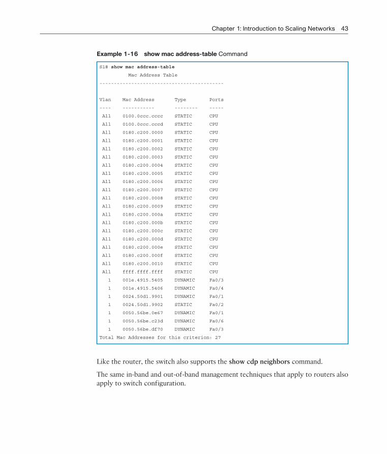
Chapter 1: Introduction to Scaling Networks 43
Example 1-16 show mac address-table Command
S1# show mac address-table
Mac Address Table
-------------------------------------------
Vlan Mac Address Type Ports
---- ----------- -------- -----
All 0100.0ccc.cccc STATIC CPU
All 0100.0ccc.cccd STATIC CPU
All 0180.c200.0000 STATIC CPU
All 0180.c200.0001 STATIC CPU
All 0180.c200.0002 STATIC CPU
All 0180.c200.0003 STATIC CPU
All 0180.c200.0004 STATIC CPU
All 0180.c200.0005 STATIC CPU
All 0180.c200.0006 STATIC CPU
All 0180.c200.0007 STATIC CPU
All 0180.c200.0008 STATIC CPU
All 0180.c200.0009 STATIC CPU
All 0180.c200.000a STATIC CPU
All 0180.c200.000b STATIC CPU
All 0180.c200.000c STATIC CPU
All 0180.c200.000d STATIC CPU
All 0180.c200.000e STATIC CPU
All 0180.c200.000f STATIC CPU
All 0180.c200.0010 STATIC CPU
All ffff.ffff.ffff STATIC CPU
1 001e.4915.5405 DYNAMIC Fa0/3
1 001e.4915.5406 DYNAMIC Fa0/4
1 0024.50d1.9901 DYNAMIC Fa0/1
1 0024.50d1.9902 STATIC Fa0/2
1 0050.56be.0e67 DYNAMIC Fa0/1
1 0050.56be.c23d DYNAMIC Fa0/6
1 0050.56be.df70 DYNAMIC Fa0/3
Total Mac Addresses for this criterion: 27
Like the router, the switch also supports the show cdp neighbors command.
The same in-band and out-of-band management techniques that apply to routers also apply to switch configuration.

44 Scaling Networks Companion Guide
Summary (1.3)
Class Activity 1.3.1.1: Layered Network Design Simulation
As the network administrator for a very small network, you want to prepare a sim-ulated-network presentation for your branch manager to explain how the network currently operates.
The small network includes the following equipment:
One 2911 Series router
One 3560 switch
One 2960 switch
Four user workstations (PCs or laptops)
One printer
Activity 1.3.1.2: Basic Switch Configurations
Go to the course online to perform this practice activity.
Packet Tracer Activity 1.3.1.3: Skills Integration Challenge
As a recently hired LAN technician, your network manager has asked you to dem-onstrate your ability to configure a small LAN. Your tasks include configuring initial settings on two switches using the Cisco IOS and configuring IP address parameters on host devices to provide end-to-end connectivity. You are to use two switches and two hosts/PCs on a cabled and powered network.
The hierarchical network design model divides network functionality into the access layer, the distribution layer, and the core layer. The Cisco Enterprise Architecture further divides the network into functional components.
A well-designed network controls traffic and limits the size of failure domains. Rout-ers and multilayer switches can be deployed in pairs so that the failure of a single device does not cause service disruptions.
A network design should include an IP addressing strategy, scalable and fast- converging routing protocols, appropriate Layer 2 protocols, and modular or clus-tered devices that can be easily upgraded to increase capacity.
InteractiveGraphic
Packet Tracer Activity

Chapter 1: Introduction to Scaling Networks 45
A mission-critical server should have a connection to two different access layer switches. It should have redundant modules when possible and a power backup source. It might be appropriate to provide multiple connections to one or more ISPs.
Security monitoring systems and IP telephony systems must have high availability and often have special design considerations.
The network designer should specify a router from the appropriate category: branch router, network edge router, or service provider router. It is important to also deploy the appropriate type of switches for a given set of requirements, switch fea-tures and specifications, and expected traffic flow.
PracticeThe following activities provide practice with the topics introduced in this chapter. The Labs and Class Activities are available in the companion Introduction to Scaling
Networks Lab Manual (ISBN 978-1-58713-325-1). The Packet Tracer Activities PKA files are found in the online course.
Class Activities
Class Activity 1.0.1.2: Network by Design
Class Activity 1.3.1.1: Layered Network Design Simulation
Labs
Lab 1.2.1.8: Selecting Switching Hardware
Packet Tracer Activities
Packet Tracer 1.2.1.7: Comparing 2960 and 3560 Switches
Packet Tracer 1.3.1.3: Skills Integration Challenge
Packet Tracer Activity

46 Scaling Networks Companion Guide
Check Your Understanding QuestionsComplete all the review questions listed here to test your understanding of the topics and concepts in this chapter. The appendix “Answers to ‘Check Your Understanding’ Questions” lists the answers.
1. What are the expected features of modern enterprise networks? (Choose two.)
A. Support for 90 percent reliability
B. Support for limited growth
C. Support for converged network traffic
D. Support for distributed administrative control
E. Support for critical applications
2. Which of the following methods help to prevent the disruption of network services? (Choose two.)
A. Changing the routing protocols at regular intervals
B. Using redundant connections to provide alternate physical paths
C. Installing duplicate equipment to provide failover services
D. Removing switches that cause loops
E. Using VLANs to segment network traffic
3. Which feature could be used in a network design to increase the bandwidth by combining multiple physical links into a single logical link?
A. VLANs
B. Trunk ports
C. EtherChannel
D. Subinterfaces
4. Which network design solution will best extend access layer connectivity to host devices?
A. Implementing EtherChannel
B. Implementing redundancy
C. Implementing routing protocols
D. Implementing wireless connectivity

Chapter 1: Introduction to Scaling Networks 47
5. How much traffic is a 48-port gigabit switch capable of generating when operating at full wire speed?
A. 44 Gb/s, because of overhead requirements
B. 48 Gb/s, by providing full bandwidth to each port
C. 24 Gb/s, because this is the maximum forwarding rate on Cisco switches
D. 1 Gb/s, because data can only be forwarded from one port at a time
6. Which type of router would an enterprise use to allow customers to access con-tent anytime and anyplace, regardless of whether they are at home or work?
A. Service provider routers
B. Network edge routers
C. Branch routers
D. Modular routers
7. What is a characteristic of out-of-band device management?
A. It requires a terminal emulation client.
B. It requires Telnet, SSH, or HTTP to access a Cisco device.
C. It requires at least one network interface on the device to be connected and operational.
D. Out-of-band device management requires a direct connection to a network interface.
8. The number of ports available on a single switch is referred to as .
9. Among the beneficial functions of a router are enhanced network security and containment of traffic.
10. Indicate the design model layer described by the following network functions:
The layer provides connectivity for the users.
The layer forwards traffic from one local network to another.
The layer provides a high-speed backbone link between dispersed networks.

This page intentionally left blank

CHAPTER 2
LAN Redundancy
ObjectivesUpon completion of this chapter, you will be able to answer the following questions:
What are the issues that you should be con-cerned with when implementing a redundant network?
How does IEEE 802.1D STP operate?
What are the different varieties of spanning tree?
How does PVST+ operate in a switched LAN environment?
How does Rapid PVST+ operate in a switched LAN environment?
What are the commands to configure PVST+ in a switched LAN environment?
What are the commands to configure Rapid PVST+ in a switched LAN environment?
What are the common STP configuration issues?
What are the purpose and operation of First Hop Redundancy Protocols?
What are the different varieties of First Hop Redundancy Protocols?
What are the commands to verify HSRP and GLBP implementations?
Key TermsThis chapter uses the following key terms. You can find the definitions in the Glossary.
First Hop Redundancy Protocols
(FHRP) page 51
broadcast storm page 54
time to live (TTL) page 54
root bridge page 59
bridge protocol data unit (BPDU) page 59
blocking state page 60
Rapid Spanning Tree Protocol (RSTP)
page 61
Multiple Spanning Tree Protocol
(MSTP) page 61
IEEE-802.1D-2004 page 61
bridge ID (BID) page 61
extended system ID page 62
root port page 62
designated port page 63
alternate and backup port page 63
disabled port page 63
default port cost page 64
bridge priority page 74
Common Spanning Tree (CST) page 78

50 Scaling Networks Companion Guide
PVST+ page 78
PortFast page 78
BPDU guard page 78
IEEE 802.1w (RSTP) page 78
Rapid PVST+ page 78
listening state page 82
learning state page 82
forwarding state page 82
disabled state page 82
edge port page 87
point-to-point link page 89
shared link page 89
Hot Standby Router Protocol (HSRP)
page 109
Virtual Router Redundancy Protocol
(VRRP) page 110
Gateway Load Balancing Protocol
(GLBP) page 110
ICMP Router Discovery Protocol (IRDP)
page 110

Chapter 2: LAN Redundancy 51
Introduction (2.0.1.1)Network redundancy is a key to maintaining network reliability. Multiple physical links between devices provide redundant paths. The network can then continue to operate when a single link or port has failed. Redundant links can also share the traf-fic load and increase capacity.
Multiple paths need to be managed so that Layer 2 loops are not created. The best paths are chosen, and an alternate path is immediately available should a primary path fail. The Spanning Tree Protocols are used to manage Layer 2 redundancy.
Redundant devices, such as multilayer switches or routers, provide the capability for a client to use an alternate default gateway should the primary default gateway fail. A client can now have multiple paths to more than one possible default gateway. First Hop Redundancy Protocols are used to manage how a client is assigned a default gateway, and to be able to use an alternate default gateway should the pri-mary default gateway fail.
This chapter focuses on the protocols used to manage these forms of redundancy. It also covers some of the potential redundancy problems and their symptoms.
Class Activity 2.0.1.2: Stormy Traffic
It is your first day on the job as a network administrator for a small- to medium-sized business. The previous network administrator left suddenly after a network upgrade took place for the business.
During the upgrade, a new switch was added. Since the upgrade, many employees complain that they are having trouble accessing the Internet and servers on your network. In fact, most of them cannot access the network at all. Your corporate manager asks you to immediately research what could be causing these connectivity problems and delays.
So you take a look at the equipment operating on your network at your main dis-tribution facility in the building. You notice that the network topology seems to be visually correct and that cables have been connected correctly, routers and switches are powered on and operational, and switches are connected together to provide backup or redundancy.
However, one thing you do notice is that all of your switches’ status lights are con-stantly blinking at a very fast pace to the point that they almost appear solid. You think you have found the problem with the connectivity issues your employees are experiencing.
52 Scaling Networks Companion Guide
Use the Internet to research STP. As you research, take notes and describe
Broadcast storm
Switching loops
The purpose of STP
Variations of STP
Complete the reflection questions that accompany the PDF file for this activity. Save your work and be prepared to share your answers with the class.
Spanning Tree Concepts (2.1)This section focuses on the purpose and operation of the Spanning Tree Protocol.
Purpose of Spanning Tree (2.1.1)
STP provides the mechanism to have redundant links at Layer 2 while avoiding the potential for loops and MAC address database instability.
Redundancy at OSI Layers 1 and 2 (2.1.1.1)
The three-tier hierarchical network design that uses core, distribution, and access layers with redundancy attempts to eliminate a single point of failure on the net-work. Multiple cabled paths between switches provide physical redundancy in a switched network. This improves the reliability and availability of the network. Hav-ing alternate physical paths for data to traverse the network makes it possible for users to access network resources, despite path disruption.
The following steps explain how redundancy works in the topology shown in Figure 2-1.
1. PC1 is communicating with PC4 over a redundant network topology.
2. When the network link between S1 and S2 is disrupted, the path between PC1 and PC4 is automatically adjusted to compensate for the disruption (shown in Figure 2-1).
3. When the network connection between S1 and S2 is restored, the path is then readjusted to route traffic directly from S2 to S1 to get to PC4.
Note
To view an animation of these steps, refer to the online course.

Chapter 2: LAN Redundancy 53
Figure 2-1 Redundancy in a Hierarchical Network
For many organizations, the availability of the network is essential to supporting business needs; therefore, the network infrastructure design is a critical business ele-ment. Path redundancy is a solution for providing the necessary availability of mul-tiple network services by eliminating the possibility of a single point of failure.
Note
The OSI Layer 1 redundancy is illustrated using multiple links and devices, but more than just physical planning is required to complete the network setup. For the redundancy to work in a systematic way, the use of OSI Layer 2 protocols such as STP is also required.
Redundancy is an important part of hierarchical design for preventing disruption of network services to users. Redundant networks require adding physical paths, but logical redundancy must also be part of the design. However, redundant paths in a switched Ethernet network can cause both physical and logical Layer 2 loops.
Logical Layer 2 loops can occur because of the natural operation of switches, specif-ically, the learning and forwarding process. When multiple paths exist between two devices on a network, and there is no spanning tree implementation on the switches, a Layer 2 loop occurs. A Layer 2 loop can result in three primary issues:
MAC database instability: Instability in the content of the MAC address table results from copies of the same frame being received on different ports of the switch. Data forwarding can be impaired when the switch consumes the resources that are coping with instability in the MAC address table.
54 Scaling Networks Companion Guide
Broadcast storms: Without some loop-avoidance process, each switch can flood broadcasts endlessly. This situation is commonly called a broadcast storm.
Multiple frame transmission: Multiple copies of unicast frames can be delivered to destination stations. Many protocols expect to receive only a single copy of each transmission. Multiple copies of the same frame can cause unrecoverable errors.
Issues with Layer 1 Redundancy: MAC Database Instability (2.1.1.2)
Ethernet frames do not have a time to live (TTL) attribute, like IP packets. As a result, if there is no mechanism enabled to block continued propagation of these frames on a switched network, they continue to propagate between switches end-lessly, or until a link is disrupted and breaks the loop. This continued propagation between switches can result in MAC database instability. This can occur because of broadcast frames forwarding.
Broadcast frames are forwarded out all switch ports, except the original ingress port. This ensures that all devices in a broadcast domain are able to receive the frame. If there is more than one path for the frame to be forwarded out, an endless loop can result. When a loop occurs, it is possible for the MAC address table on a switch to constantly change with the updates from the broadcast frames, resulting in MAC database instability.
The following steps demonstrate the MAC database instability issue. Figure 2-2 shows a snapshot during Step 4.
1. PC1 sends out a broadcast frame to S2. S2 receives the broadcast frame on F0/11. When S2 receives the broadcast frame, it updates its MAC address table to record that PC1 is available on port F0/11.
2. Because it is a broadcast frame, S2 forwards the frame out all ports, including Trunk1 and Trunk2. When the broadcast frame arrives at S3 and S1, they update their MAC address tables to indicate that PC1 is available out port F0/1 on S1 and out port F0/2 on S3.
3. Because it is a broadcast frame, S3 and S1 forward the frame out all ports, except the ingress port. S3 sends the broadcast frame from PC1 to S1. S1 sends the broadcast frame from PC1 to S3. Each switch updates its MAC address table with the incorrect port for PC1.
4. Each switch again forwards the broadcast frame out all of its ports, except the ingress port, resulting in both switches forwarding the frame to S2 (shown in Figure 2-2).

Chapter 2: LAN Redundancy 55
Figure 2-2 MAC Database Instability Example
5. When S2 receives the broadcast frames from S3 and S1, the MAC address table is updated again, this time with the last entry received from the other two switches.
Note
To view an animation of these steps, refer to the online course.
This process repeats over and over again until the loop is broken by physically dis-connecting the connections causing the loop or powering down one of the switches in the loop. This creates a high CPU load on all switches caught in the loop. Because the same frames are constantly being forwarded back and forth between all switches in the loop, the CPU of the switch must process a lot of data. This slows down per-formance on the switch when legitimate traffic arrives.
A host caught in a network loop is not accessible to other hosts on the network. Additionally, because of the constant changes in the MAC address table, the switch does not know out of which port to forward unicast frames. In the previous exam-ple, the switches will have the incorrect ports listed for PC1. Any unicast frame des-tined for PC1 loops around the network, just as the broadcast frames do. More and more frames looping around the network eventually create a broadcast storm.

56 Scaling Networks Companion Guide
Issues with Layer 1 Redundancy: Broadcast Storms (2.1.1.3)
A broadcast storm occurs when there are so many broadcast frames caught in a Layer 2 loop that all available bandwidth is consumed. Consequently, no bandwidth is available for legitimate traffic and the network becomes unavailable for data com-munication. This is an effective denial of service.
A broadcast storm is inevitable on a looped network. As more devices send broad-casts over the network, more traffic is caught within the loop, consuming resources. This eventually creates a broadcast storm that causes the network to fail.
There are other consequences of broadcast storms. Because broadcast traffic is for-warded out every port on a switch, all connected devices have to process all broad-cast traffic that is being flooded endlessly around the looped network. This can cause the end device to malfunction because of the high processing requirements for sustaining such a high traffic load on the NIC.
The following steps demonstrate the broadcast storm issue. Figure 2-3 shows the final result during Step 6.
1. PC1 sends a broadcast frame out onto the looped network.
2. The broadcast frame loops between all the interconnected switches on the network.
3. PC4 also sends a broadcast frame out on to the looped network.
4. The PC4 broadcast frame also gets caught in the loop between all the intercon-nected switches, just like the PC1 broadcast frame.
5. As more devices send broadcasts over the network, more traffic is caught within the loop, consuming resources. This eventually creates a broadcast storm that causes the network to fail.
6. When the network is fully saturated with broadcast traffic that is looping between the switches, new traffic is discarded by the switch because it is unable to process it. In Figure 2-3, S2 is now discarding additional frames.
Note
To view an animation of these steps, refer to the online course.
Because devices connected to a network are regularly sending out broadcast frames, such as ARP requests, a broadcast storm can develop in seconds. As a result, when a loop is created, the switched network is quickly brought down.
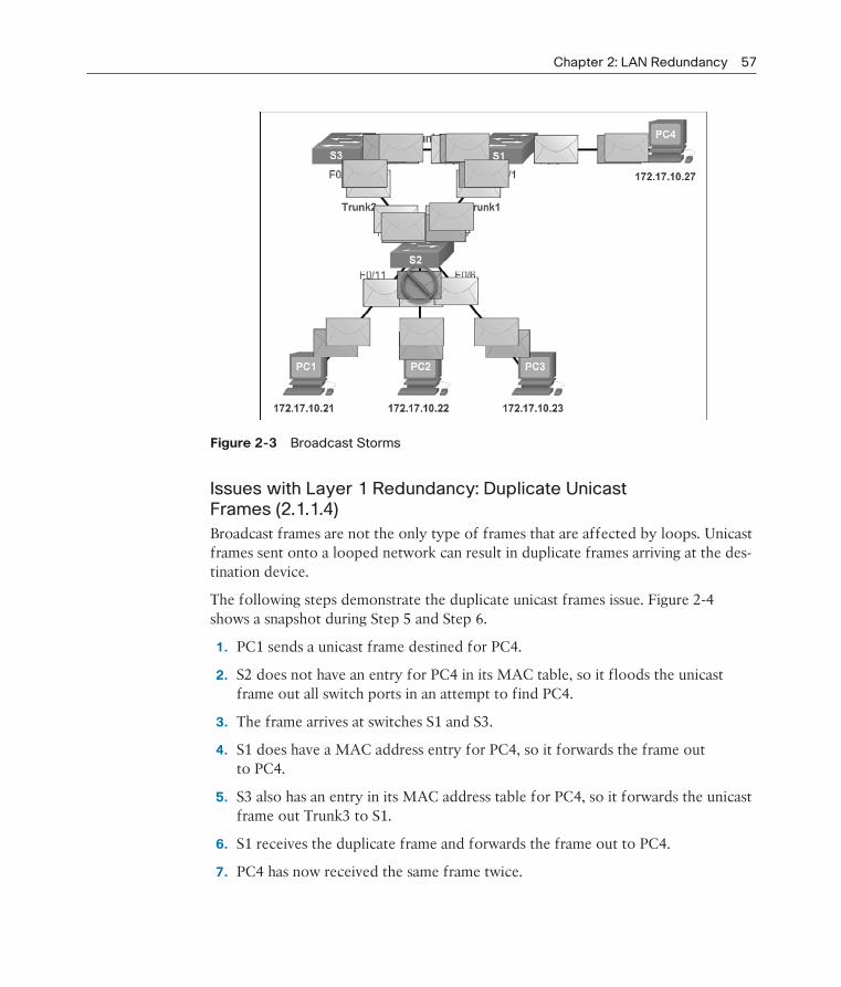
Chapter 2: LAN Redundancy 57
Figure 2-3 Broadcast Storms
Issues with Layer 1 Redundancy: Duplicate Unicast Frames (2.1.1.4)
Broadcast frames are not the only type of frames that are affected by loops. Unicast frames sent onto a looped network can result in duplicate frames arriving at the des-tination device.
The following steps demonstrate the duplicate unicast frames issue. Figure 2-4 shows a snapshot during Step 5 and Step 6.
1. PC1 sends a unicast frame destined for PC4.
2. S2 does not have an entry for PC4 in its MAC table, so it floods the unicast frame out all switch ports in an attempt to find PC4.
3. The frame arrives at switches S1 and S3.
4. S1 does have a MAC address entry for PC4, so it forwards the frame out to PC4.
5. S3 also has an entry in its MAC address table for PC4, so it forwards the unicast frame out Trunk3 to S1.
6. S1 receives the duplicate frame and forwards the frame out to PC4.
7. PC4 has now received the same frame twice.
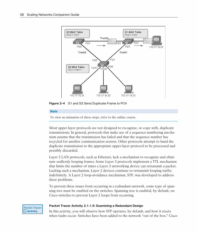
58 Scaling Networks Companion Guide
Figure 2-4 S1 and S3 Send Duplicate Frame to PC4
Note
To view an animation of these steps, refer to the online course.
Most upper-layer protocols are not designed to recognize, or cope with, duplicate transmissions. In general, protocols that make use of a sequence-numbering mecha-nism assume that the transmission has failed and that the sequence number has recycled for another communication session. Other protocols attempt to hand the duplicate transmission to the appropriate upper-layer protocol to be processed and possibly discarded.
Layer 2 LAN protocols, such as Ethernet, lack a mechanism to recognize and elimi-nate endlessly looping frames. Some Layer 3 protocols implement a TTL mechanism that limits the number of times a Layer 3 networking device can retransmit a packet. Lacking such a mechanism, Layer 2 devices continue to retransmit looping traffic indefinitely. A Layer 2 loop-avoidance mechanism, STP, was developed to address these problems.
To prevent these issues from occurring in a redundant network, some type of span-ning tree must be enabled on the switches. Spanning tree is enabled, by default, on Cisco switches to prevent Layer 2 loops from occurring.
Packet Tracer Activity 2.1.1.5: Examining a Redundant Design
In this activity, you will observe how STP operates, by default, and how it reacts when faults occur. Switches have been added to the network “out of the box.” Cisco
Packet Tracer Activity

Chapter 2: LAN Redundancy 59
switches can be connected to a network without any additional action required by the network administrator. For the purpose of this activity, the bridge priority was modified.
STP Operation (2.1.2)
STP uses the concepts of a root bridge, port roles, and path costs to calculate which links to use in a redundant topology.
Spanning Tree Algorithm: Introduction (2.1.2.1)
Redundancy increases the availability of the network topology by protecting the network from a single point of failure, such as a failed network cable or switch. When physical redundancy is introduced into a design, loops and duplicate frames occur. Loops and duplicate frames have severe consequences for a switched net-work. The Spanning Tree Protocol (STP) was developed to address these issues.
STP ensures that there is only one logical path between all destinations on the net-work by intentionally blocking redundant paths that could cause a loop. A port is considered blocked when user data is prevented from entering or leaving that port. This does not include bridge protocol data unit (BPDU) frames that are used by STP to prevent loops. Blocking the redundant paths is critical to preventing loops on the network. The physical paths still exist to provide redundancy, but these paths are disabled to prevent the loops from occurring. If the path is ever needed to compen-sate for a network cable or switch failure, STP recalculates the paths and unblocks the necessary ports to allow the redundant path to become active.
In Figure 2-5, all switches have STP enabled:
Figure 2-5 Normal STP Operation

60 Scaling Networks Companion Guide
1. PC1 sends a broadcast out onto the network.
2. S2 is configured with STP and has set the port for Trunk2 to a blocking state, as shown in Figure 2-5. The blocking state prevents ports from being used to for-ward user data, thus preventing a loop from occurring. S2 forwards a broadcast frame out all switch ports, except the originating port from PC1 and the port for Trunk2.
3. S1 receives the broadcast frame and forwards it out all of its switch ports, where it reaches PC4 and S3. S3 forwards the frame out the port for Trunk2 and S2 drops the frame. The Layer 2 loop is prevented.
Note
To view an animation of these steps, refer to the online course.
In Figure 2-6, STP recalculates the path when a failure occurs.
Figure 2-6 STP Compensates for Network Failure
1. PC1 sends a broadcast out onto the network.
2. The broadcast is then forwarded around the network, just as in the previous animation.
3. The trunk link between S2 and S1 fails, resulting in the previous path being disrupted.
4. S2 unblocks the previously blocked port for Trunk2 and allows the broadcast traffic to traverse the alternate path around the network, permitting communica-tion to continue. If this link comes back up, STP reconverges and the port on S2 is again blocked.

Chapter 2: LAN Redundancy 61
Note
To view an animation of these steps, refer to the online course.
STP prevents loops from occurring by configuring a loop-free path through the net-work using strategically placed “blocking-state” ports. The switches running STP are able to compensate for failures by dynamically unblocking the previously blocked ports and permitting traffic to traverse the alternate paths.
Up to now, we have used the term Spanning Tree Protocol and the acronym STP. The usage of the Spanning Tree Protocol term and the STP acronym can be mislead-ing. Many professionals generically use these to refer to various implementations of spanning tree, such as Rapid Spanning Tree Protocol (RSTP) and Multiple
Spanning Tree Protocol (MSTP). In order to communicate spanning tree concepts correctly, it is important to refer to the particular implementation or standard in context. The latest IEEE documentation on spanning tree, IEEE-802-1D-2004, says “STP has now been superseded by the Rapid Spanning Tree Protocol (RSTP).” So one sees that the IEEE uses “STP” to refer to the original implementation of spanning tree and “RSTP” to describe the version of spanning tree specified in IEEE-802.1D-2004. In this book, when the original Spanning Tree Protocol is the context of a discussion, the phrase “original 802.1D spanning tree” is used to avoid confusion.
Note
STP is based on an algorithm invented by Radia Perlman while working for Digital Equipment Corporation, and published in the 1985 paper “An Algorithm for Distributed Computation of a Spanning Tree in an Extended LAN.”
Spanning Tree Algorithm: Port Roles (2.1.2.2)
IEEE 802.1D STP uses the Spanning Tree Algorithm (STA) to determine which switch ports on a network must be put in blocking state to prevent loops from occurring. The STA designates a single switch as the root bridge and uses it as the reference point for all path calculations. In Figure 2-7, the root bridge (switch S1) is chosen through an election process. All switches participating in STP exchange BPDU frames to determine which switch has the lowest bridge ID (BID) on the net-work. The switch with the lowest BID automatically becomes the root bridge for the STA calculations.
Note
For simplicity, assume until otherwise indicated that all ports on all switches are assigned to VLAN 1. Each switch has a unique MAC address associated with VLAN 1.

62 Scaling Networks Companion Guide
Figure 2-7 STP Algorithm
A BPDU is a messaging frame exchanged by switches for STP. Each BPDU contains a BID that identifies the switch that sent the BPDU. The BID contains a priority value, the MAC address of the sending switch, and an optional extended system ID. The lowest BID value is determined by the combination of these three fields.
After the root bridge has been determined, the STA calculates the shortest path to it. Each switch uses the STA to determine which ports to block. While the STA deter-mines the best paths to the root bridge for all switch ports in the broadcast domain, traffic is prevented from being forwarded through the network. The STA considers both path and port costs when determining which ports to block. The path costs are calculated using port cost values associated with port speeds for each switch port along a given path. The sum of the port cost values determines the overall path cost to the root bridge. If there is more than one path to choose from, STA chooses the path with the lowest path cost.
When the STA has determined which paths are most desirable relative to each switch, it assigns port roles to the participating switch ports. The port roles describe their relation in the network to the root bridge and whether they are allowed to forward traffic:
Root ports: Switch ports closest to the root bridge. In Figure 2-7, the root port on S2 is F0/1 configured for the trunk link between S2 and S1. The root port on S3 is F0/1, configured for the trunk link between S3 and S1. Root ports are selected on a per-switch basis.

Chapter 2: LAN Redundancy 63
Designated ports: All nonroot ports that are still permitted to forward traffic on the network. In Figure 2-7, switch ports (F0/1 and F0/2) on S1 are designated ports. S2 also has its port F0/2 configured as a designated port. Designated ports are selected on a per-trunk basis. If one end of a trunk is a root port, the other end is a designated port. All ports on the root bridge are designated ports.
Alternate and backup ports: Alternate ports and backup ports are configured to be in a blocking state to prevent loops. In the figure, the STA configured port F0/2 on S3 in the alternate role. Port F0/2 on S3 is in the blocking state. Alternate ports are selected only on trunk links where neither end is a root port. Notice in Figure 2-7 that only one end of the trunk is blocked. This allows for faster transition to a forwarding state, when necessary. (Blocking ports only come into play when two ports on the same switch are connected to each other through a hub or single cable.)
Disabled ports: A disabled port is a switch port that is shut down.
Spanning Tree Algorithm: Root Bridge (2.1.2.3)
As shown in Figure 2-8, every spanning tree instance (switched LAN or broadcast domain) has a switch designated as the root bridge. The root bridge serves as a ref-erence point for all spanning tree calculations to determine which redundant paths to block.
Figure 2-8 Root Bridge
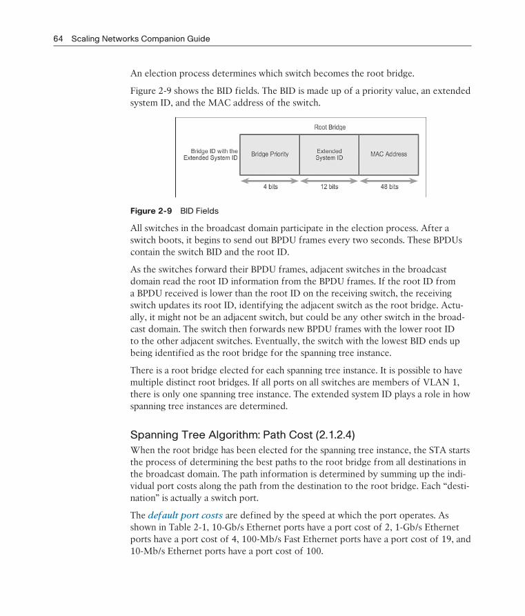
64 Scaling Networks Companion Guide
An election process determines which switch becomes the root bridge.
Figure 2-9 shows the BID fields. The BID is made up of a priority value, an extended system ID, and the MAC address of the switch.
Figure 2-9 BID Fields
All switches in the broadcast domain participate in the election process. After a switch boots, it begins to send out BPDU frames every two seconds. These BPDUs contain the switch BID and the root ID.
As the switches forward their BPDU frames, adjacent switches in the broadcast domain read the root ID information from the BPDU frames. If the root ID from a BPDU received is lower than the root ID on the receiving switch, the receiving switch updates its root ID, identifying the adjacent switch as the root bridge. Actu-ally, it might not be an adjacent switch, but could be any other switch in the broad-cast domain. The switch then forwards new BPDU frames with the lower root ID to the other adjacent switches. Eventually, the switch with the lowest BID ends up being identified as the root bridge for the spanning tree instance.
There is a root bridge elected for each spanning tree instance. It is possible to have multiple distinct root bridges. If all ports on all switches are members of VLAN 1, there is only one spanning tree instance. The extended system ID plays a role in how spanning tree instances are determined.
Spanning Tree Algorithm: Path Cost (2.1.2.4)
When the root bridge has been elected for the spanning tree instance, the STA starts the process of determining the best paths to the root bridge from all destinations in the broadcast domain. The path information is determined by summing up the indi-vidual port costs along the path from the destination to the root bridge. Each “desti-nation” is actually a switch port.
The default port costs are defined by the speed at which the port operates. As shown in Table 2-1, 10-Gb/s Ethernet ports have a port cost of 2, 1-Gb/s Ethernet ports have a port cost of 4, 100-Mb/s Fast Ethernet ports have a port cost of 19, and 10-Mb/s Ethernet ports have a port cost of 100.

Chapter 2: LAN Redundancy 65
Table 2-1 Best Paths to the Root Bridge
Link Speed Cost (Revised IEEE
Specification)
Cost (Previous IEEE
Specification)
10 Gbps 2 1
1 Gbps 4 1
100 Mbps 19 10
10 Mbps 100 100
Note
As newer, faster Ethernet technologies enter the marketplace, the path cost values can change to accommodate the different speeds available. The nonlinear numbers in Table 2-1 accom-modate some improvements to the older Ethernet standard. The values have already been changed to accommodate the 10-Gb/s Ethernet standard. To illustrate the continued change associated with high-speed networking, Catalyst 4500 and 6500 switches support a longer path cost method. For example, 10 Gb/s has a 2000 path cost, 100 Gb/s has a 200 path cost, and 1 Tb/s has a 20 path cost.
Although switch ports have a default port cost associated with them, the port cost is configurable. The ability to configure individual port costs gives the administrator the flexibility to manually control the spanning tree paths to the root bridge.
To configure the port cost of an interface, enter the spanning-tree cost value com-mand in interface configuration mode. The value can be between 1 and 200,000,000.
In Example 2-1, switch port F0/1 has been configured with a port cost of 25 using the spanning-tree cost 25 interface configuration mode command on the F0/1 interface.
Example 2-1 Configure Port Cost
S2# configure terminal
Enter configuration commands, one per line. End with CNTL/Z.
S2(config)# interface f0/1
S2(config-if)# spanning-tree cost 25
S2(config-if)# end
S2#
To restore the port cost to the default value of 19, enter the no spanning-tree cost interface configuration mode command.
The path cost is equal to the sum of all the port costs along the path to the root bridge, as shown in Figure 2-10.

66 Scaling Networks Companion Guide
Figure 2-10 Path Cost
Paths with the lowest cost become preferred, and all other redundant paths are blocked. In the example, the path cost from S2 to the root bridge S1, over path 1 is 19 (based on the IEEE-specified individual port cost), while the path cost over path 2 is 38. Because path 1 has a lower overall path cost to the root bridge, it is the preferred path. STP then configures the redundant path to be blocked, preventing a loop from occurring.
To verify the port and path cost to the root bridge, enter the show spanning-tree command, as shown in Example 2-2.
Example 2-2 show spanning-tree Command
S1# show spanning-tree
VLAN0001
Spanning tree enabled protocol ieee
Root ID Priority 27577
Address 000A.0033.0033
Cost 19
Port 1
Hello Time 2 sec Max Age 20 sec Forward Delay 15 sec
Bridge ID Priority 32769 (priority 32768 sys-id-ext 1)
Address 000A.0011.1111

Chapter 2: LAN Redundancy 67
Hello Time 2 sec Max Age 20 sec Forward Delay 15 sec
Aging Time 15 sec
Interface Role Sts Cost Prio.Nbr Type
------------------- ---- --- --------- -------- ------------------------
Fa0/1 Root FWD 19 128.1 Edge P2p
Fa0/2 Desg FWD 19 128.2 Edge P2p
The Cost field near the top of the output is the total path cost to the root bridge. This value changes depending on how many switch ports must be traversed to get to the root bridge. In the output, each interface is also identified with an individual port cost of 19.
802.1D BPDU Frame Format (2.1.2.5)
The spanning tree algorithm depends on the exchange of BPDUs to determine a root bridge. As shown in Table 2-2, a BPDU frame contains 12 distinct fields that convey path and priority information used to determine the root bridge and paths to the root bridge.
Table 2-2 BPDU Fields
Field Number Bytes Field
1–4 2 Protocol ID
1 Version
1 Message type
1 Flags
5–8 8 Root ID
4 Cost of path
8 Bridge ID
2 Port ID
9–12 2 Message age
2 Max age
2 Hello time
2 Forward delay

68 Scaling Networks Companion Guide
The first four fields identify the protocol, version, message type, and status flags.
The next four fields are used to identify the root bridge and the cost of the path to the root bridge.
The last four fields are all timer fields that determine how frequently BPDU messages are sent and how long the information received through the BPDU process (next topic) is retained.
Figure 2-11 shows a BPDU frame that was captured using Wireshark.
Figure 2-11 Captured BPDU Frame
In the capture, the BPDU frame contains more fields than previously described. The BPDU message is encapsulated in an Ethernet frame when it is transmitted across the network. The 802.3 header indicates the source and destination addresses of the BPDU frame. This frame has a destination MAC address of 01:80:C2:00:00:00, which is a multicast address for the spanning tree group. When a frame is addressed with this MAC address, each switch that is configured for spanning tree accepts and reads the information from the frame; all other devices on the network disregard the frame.
Also note in the capture, the root ID and the BID are the same in the captured BPDU frame. This indicates that the frame was captured from a root bridge. The timers are all set to the default values.
BPDU Propagation and Process (2.1.2.6)
Each switch in the broadcast domain initially assumes that it is the root bridge for a spanning tree instance, so the BPDU frames sent contain the BID of the local switch as the root ID. By default, BPDU frames are sent every two seconds after a switch is booted; that is, the default value of the Hello timer specified in the BPDU frame

Chapter 2: LAN Redundancy 69
is two seconds. Each switch maintains local information about its own BID, the root ID, and the path cost to the root.
When adjacent switches receive a BPDU frame, they compare the root ID from the BPDU frame with the local root ID. If the root ID in the BPDU is lower than the local root ID, the switch updates the local root ID and the ID in its BPDU messages. These messages indicate the new root bridge on the network. The distance to the root bridge is also indicated by the path cost update. For example, if the BPDU was received on a Fast Ethernet switch port, the path cost would increment by 19. If the local root ID is lower than the root ID received in the BPDU frame, the BPDU frame is discarded.
After a root ID has been updated to identify a new root bridge, all subsequent BPDU frames sent from that switch contain the new root ID and updated path cost. That way, all other adjacent switches are able to see the lowest root ID identified at all times. As the BPDU frames pass between other adjacent switches, the path cost is con-tinually updated to indicate the total path cost to the root bridge. Each switch in the spanning tree uses its path costs to identify the best possible path to the root bridge.
The following summarizes the BPDU process:
Note
Priority is the initial deciding factor when electing a root bridge. If the priorities of all the switches are the same, the device with the lowest MAC address becomes the root bridge.
1. Initially, each switch identifies itself as the root bridge. S2 forwards BPDU frames out all switch ports. (See Figure 2-12.)
Figure 2-12 BPDU Process: Step 1
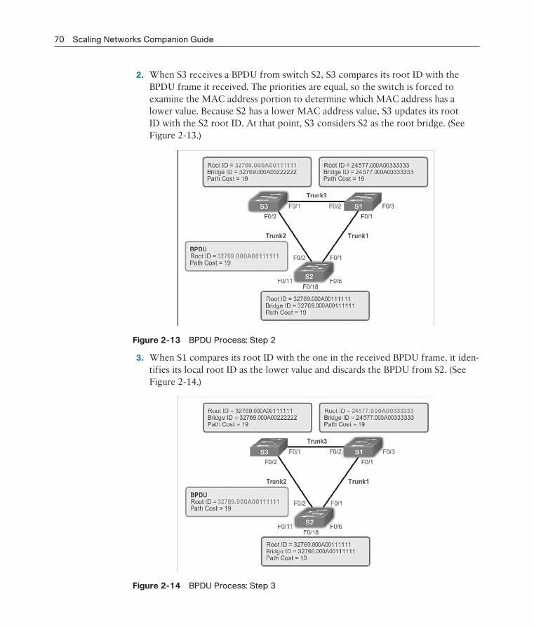
70 Scaling Networks Companion Guide
2. When S3 receives a BPDU from switch S2, S3 compares its root ID with the BPDU frame it received. The priorities are equal, so the switch is forced to examine the MAC address portion to determine which MAC address has a lower value. Because S2 has a lower MAC address value, S3 updates its root ID with the S2 root ID. At that point, S3 considers S2 as the root bridge. (See Figure 2-13.)
Figure 2-13 BPDU Process: Step 2
3. When S1 compares its root ID with the one in the received BPDU frame, it iden-tifies its local root ID as the lower value and discards the BPDU from S2. (See Figure 2-14.)
Figure 2-14 BPDU Process: Step 3
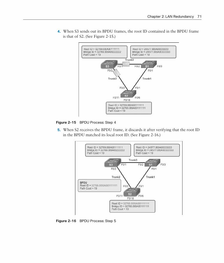
Chapter 2: LAN Redundancy 71
4. When S3 sends out its BPDU frames, the root ID contained in the BPDU frame is that of S2. (See Figure 2-15.)
Figure 2-15 BPDU Process: Step 4
5. When S2 receives the BPDU frame, it discards it after verifying that the root ID in the BPDU matched its local root ID. (See Figure 2-16.)
Figure 2-16 BPDU Process: Step 5

72 Scaling Networks Companion Guide
6. Because S1 has a lower priority value in its root ID, it discards the BPDU frame received from S3. (See Figure 2-17.)
Figure 2-17 BPDU Process: Step 6
7. S1 sends out its BPDU frames. (See Figure 2-18.)
Figure 2-18 BPDU Process: Step 7
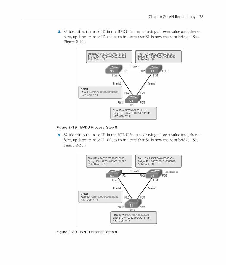
Chapter 2: LAN Redundancy 73
8. S3 identifies the root ID in the BPDU frame as having a lower value and, there-fore, updates its root ID values to indicate that S1 is now the root bridge. (See Figure 2-19.)
Figure 2-19 BPDU Process: Step 8
9. S2 identifies the root ID in the BPDU frame as having a lower value and, there-fore, updates its root ID values to indicate that S1 is now the root bridge. (See Figure 2-20.)
Figure 2-20 BPDU Process: Step 9

74 Scaling Networks Companion Guide
Extended System ID (2.1.2.7)
The bridge ID (BID) is used to determine the root bridge on a network. The BID field of a BPDU frame contains three separate fields:
Bridge priority
Extended system ID
MAC address
Each field is used during the root bridge election.
Bridge PriorityThe bridge priority is a configurable value that can be used to influence which switch becomes the root bridge. The switch with the lowest priority, which implies the lowest BID, becomes the root bridge because a lower-priority value takes prece-dence. For example, to ensure that a specific switch is always the root bridge, set the priority to a lower value than the rest of the switches on the network. The default priority value for all Cisco switches is 32768. The range is 0 to 61440 in increments of 4096. Valid priority values are 0, 4096, 8192, 12288, 16384, 20480, 24576, 28672, 32768, 36864, 40960, 45056, 49152, 53248, 57344, and 61440. All other values are rejected. A bridge priority of 0 takes precedence over all other bridge priorities.
Extended System IDEarly implementations of IEEE 802.1D were designed for networks that did not use VLANs. There was a single common spanning tree across all switches. For this reason, in older Cisco switches, the extended system ID could be omitted in BPDU frames. As VLANs became common for network infrastructure segmentation, 802.1D was enhanced to include support for VLANs, requiring the VLAN ID to be included in the BPDU frame. VLAN information is included in the BPDU frame through the use of the extended system ID. All newer switches include the use of the extended system ID by default.
As shown in Figure 2-21, the bridge priority field is 2 bytes or 16 bits in length; 4 bits are used for the bridge priority and 12 bits for the extended system ID, which identifies the VLAN participating in this particular STP process.
Using these 12 bits for the extended system ID reduces the bridge priority to 4 bits. This process reserves the rightmost 12 bits for the VLAN ID and the far left 4 bits for the bridge priority. This explains why the bridge priority value can only be con-figured in multiples of 4096, or 212. If the far left bits are 0001, the bridge priority
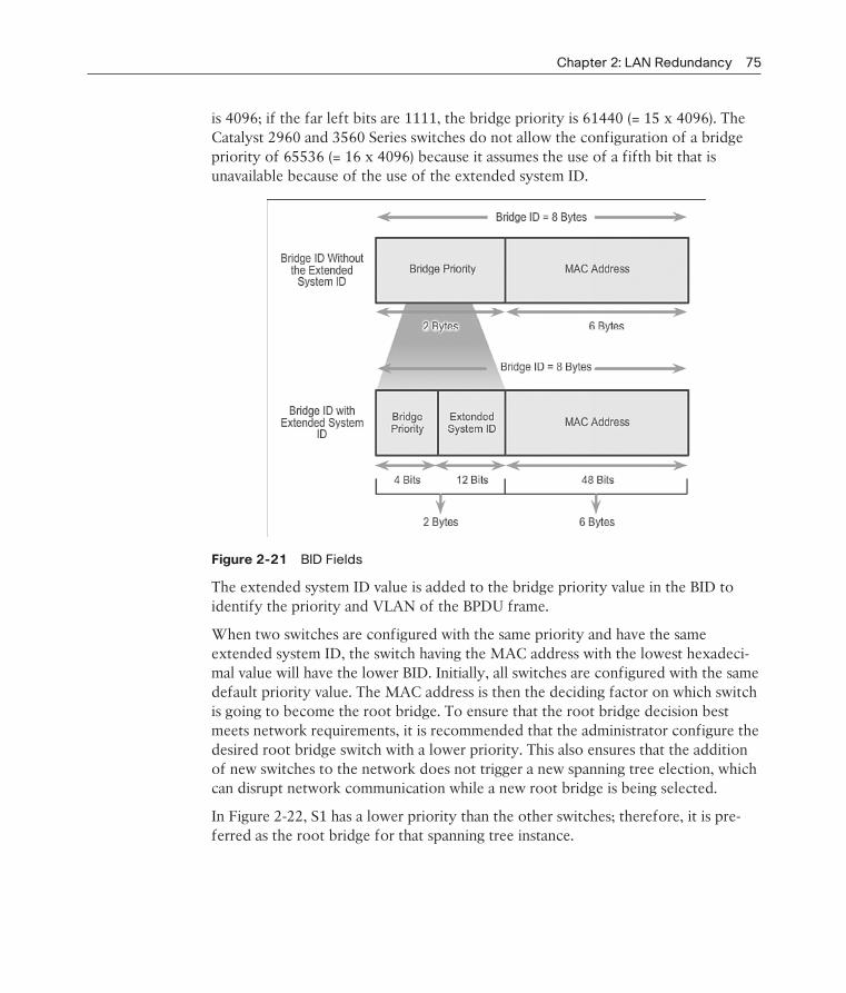
Chapter 2: LAN Redundancy 75
is 4096; if the far left bits are 1111, the bridge priority is 61440 (= 15 x 4096). The Catalyst 2960 and 3560 Series switches do not allow the configuration of a bridge priority of 65536 (= 16 x 4096) because it assumes the use of a fifth bit that is unavailable because of the use of the extended system ID.
Figure 2-21 BID Fields
The extended system ID value is added to the bridge priority value in the BID to identify the priority and VLAN of the BPDU frame.
When two switches are configured with the same priority and have the same extended system ID, the switch having the MAC address with the lowest hexadeci-mal value will have the lower BID. Initially, all switches are configured with the same default priority value. The MAC address is then the deciding factor on which switch is going to become the root bridge. To ensure that the root bridge decision best meets network requirements, it is recommended that the administrator configure the desired root bridge switch with a lower priority. This also ensures that the addition of new switches to the network does not trigger a new spanning tree election, which can disrupt network communication while a new root bridge is being selected.
In Figure 2-22, S1 has a lower priority than the other switches; therefore, it is pre-ferred as the root bridge for that spanning tree instance.

76 Scaling Networks Companion Guide
Figure 2-22 Priority-Based Decision
When all switches are configured with the same priority, as is the case with all switches kept in the default configuration with a priority of 32768, the MAC address becomes the deciding factor for which switch becomes the root bridge, as shown in Figure 2-23.
Note
In the example, the priority of all the switches is 32769. The value is based on the 32768 default priority and the VLAN 1 assignment associated with each switch (32768+1).
The MAC address with the lowest hexadecimal value is considered to be the pre-ferred root bridge. In the example, S2 has the lowest value for its MAC address and is, therefore, designated as the root bridge for that spanning tree instance.
Activity 2.1.2.8: Identify 802.1D Port Roles
Go to the course online to perform this practice activity.
Video Demonstration 2.1.2.9: Observing Spanning Tree Protocol Operation
View the video in the online course for an understanding of STP operation.
InteractiveGraphic
Video

Chapter 2: LAN Redundancy 77
Figure 2-23 MAC-Based Decision
Lab 2.1.2.10: Building a Switched Network with Redundant Links
In this lab, you will complete the following objectives:
Part 1: Build the Network and Configure Basic Device Settings
Part 2: Determine the Root Bridge
Part 3: Observe STP Port Selection Based on Port Cost
Part 4: Observe STP Port Selection Based on Port Priority
Varieties of Spanning Tree Protocols (2.2)STP has evolved into several different versions since the original specification. Some versions are IEEE standards, while others are proprietary. This section reviews the features unique to each of the more popular STP versions.
Overview (2.2.1)
To begin to understand the scope of STP versions available, let’s briefly look at a list of all of them.
78 Scaling Networks Companion Guide
List of Spanning Tree Protocols (2.2.1.1)
Several varieties of spanning tree protocols have emerged since the original IEEE 802.1D.
The varieties of spanning tree protocols include
STP: This is the original IEEE 802.1D version (802.1D-1998 and earlier) that provides a loop-free topology in a network with redundant links. Common
Spanning Tree (CST) assumes one spanning tree instance for the entire bridged network, regardless of the number of VLANs.
PVST+: This is a Cisco enhancement of STP that provides a separate 802.1D spanning tree instance for each VLAN configured in the network. The separate instance supports PortFast, UplinkFast, BackboneFast, BPDU guard, BPDU filter, root guard, and loop guard.
802.1D-2004: This is an updated version of the STP standard, incorporating IEEE 802.1w.
Rapid Spanning Tree Protocol (RSTP) or IEEE 802.1w: This is an evolution of STP that provides faster convergence than STP.
Rapid PVST+: This is a Cisco enhancement of RSTP that uses PVST+. Rapid PVST+ provides a separate instance of 802.1w per VLAN. The separate instance supports PortFast, BPDU guard, BPDU filter, root guard, and loop guard.
Multiple Spanning Tree Protocol (MSTP): This is an IEEE standard inspired by the earlier Cisco proprietary Multiple Instance STP (MISTP) implementation. MSTP maps multiple VLANs into the same spanning tree instance. The Cisco implementation of MSTP is MST, which provides up to 16 instances of RSTP and combines many VLANs with the same physical and logical topology into a common RSTP instance. Each instance supports PortFast, BPDU guard, BPDU filter, root guard, and loop guard.
A network professional, whose duties include switch administration, might be required to decide which type of spanning tree protocol to implement.
Note
The legacy Cisco-proprietary features UplinkFast and BackboneFast are not described in this course. These features are superseded by the implementation of Rapid PVST+, which incor-porates these features as part of the implementation of the RSTP standard.
Chapter 2: LAN Redundancy 79
Characteristics of the Spanning Tree Protocols (2.2.1.2)
These are characteristics of the various spanning tree protocols:
STP: Assumes one IEEE 802.1D spanning tree instance for the entire bridged network, regardless of the number of VLANs. Because there is only one instance, the CPU and memory requirements for this version are lower than for the other protocols. However, because there is only one instance, there is only one root bridge and one tree. Traffic for all VLANs flows over the same path, which can lead to suboptimal traffic flows. Because of the limitations of 802.1D, this version is slow to converge.
PVST+: A Cisco enhancement of STP that provides a separate instance of the Cisco implementation of 802.1D for each VLAN that is configured in the net-work. The separate instance supports PortFast, UplinkFast, BackboneFast, BPDU guard, BPDU filter, root guard, and loop guard. Creating an instance for each VLAN increases the CPU and memory requirements, but allows for per-VLAN root bridges. This design allows the spanning tree to be optimized for the traf-fic of each VLAN. Convergence of this version is similar to the convergence of 802.1D. However, convergence is per-VLAN.
RSTP (or IEEE 802.1w): An evolution of spanning tree that provides faster convergence than the original 802.1D implementation. This version addresses many convergence issues, but because it still provides a single instance of STP, it does not address the suboptimal traffic flow issues. To support that faster con-vergence, the CPU usage and memory requirements of this version are slightly higher than those of CST, but less than those of RSTP+.
Rapid PVST+: A Cisco enhancement of RSTP that uses PVST+. It provides a separate instance of 802.1w per VLAN. The separate instance supports PortFast, BPDU guard, BPDU filter, root guard, and loop guard. This version addresses both the convergence issues and the suboptimal traffic flow issues. However, this version has the largest CPU and memory requirements.
MSTP: The IEEE 802.1s standard, inspired by the earlier Cisco-proprietary MISTP implementation. To reduce the number of required STP instances, MSTP maps multiple VLANs that have the same traffic flow requirements into the same spanning tree instance.
MST: The Cisco implementation of MSTP, which provides up to 16 instances of RSTP (802.1w) and combines many VLANs with the same physical and logical topology into a common RSTP instance. Each instance supports PortFast, BPDU guard, BPDU filter, root guard, and loop guard. The CPU and memory require-ments of this version are less than those of Rapid PVST+, but more than those of RSTP.
Table 2-3 summarizes these STP characteristics.

80 Scaling Networks Companion Guide
Table 2-3 Spanning Tree Protocol Characteristics
Protocol Standard Resources
Needed
Convergence Tree Calculation
STP 802.1D Low Slow All VLANs
PVST+ Cisco High Slow Per VLAN
RSTP 802.1w Medium Fast All VLANs
Rapid PVST+ Cisco Very high Fast Per VLAN
MSTP 802.1s, Cisco Medium or high Fast Per Instance
The default spanning tree mode for Cisco Catalyst switches is PVST+, which is enabled on all ports. PVST+ has much slower convergence after a topology change than Rapid PVST+.
Note
It is important to distinguish between the legacy IEEE 802.1D-1998 (and earlier) standard and the IEEE 802.1D-2004 standard. IEEE 802.1D-2004 incorporates RSTP functional-ity, while IEEE 802.1D-1998 refers to the original implementation of the spanning tree algorithm. Newer Cisco switches running newer versions of the IOS, such as Catalyst 2960 switches with IOS 15.0, run PVST+ by default, but incorporate many of the specifications of IEEE 802.1D-1998 in this mode (such as alternate ports in place of the former nondesignated ports). But to run rapid spanning tree on such a switch, it still must be explicitly configured for rapid spanning tree mode.
Activity 2.2.1.3: Identify Types of Spanning Tree Protocols
Go to the course online to perform this practice activity.
PVST+ (2.2.2)
PVST+ is a Cisco implementation of STP and is the default STP mode on Cisco Catalyst switches.
Overview of PVST+ (2.2.2.1)
The original IEEE 802.1D standard defines a Common Spanning Tree (CST) that assumes only one spanning tree instance for the entire switched network, regardless of the number of VLANs. A network running CST has these characteristics:
No load sharing is possible. One uplink must block for all VLANs.
The CPU is spared. Only one instance of spanning tree must be computed.
InteractiveGraphic
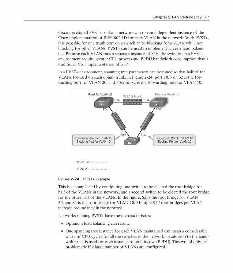
Chapter 2: LAN Redundancy 81
Cisco developed PVST+ so that a network can run an independent instance of the Cisco implementation of IEEE 802.1D for each VLAN in the network. With PVST+, it is possible for one trunk port on a switch to be blocking for a VLAN while not blocking for other VLANs. PVST+ can be used to implement Layer 2 load balanc-ing. Because each VLAN runs a separate instance of STP, the switches in a PVST+ environment require greater CPU process and BPDU bandwidth consumption than a traditional CST implementation of STP.
In a PVST+ environment, spanning tree parameters can be tuned so that half of the VLANs forward on each uplink trunk. In Figure 2-24, port F0/3 on S2 is the for-warding port for VLAN 20, and F0/2 on S2 is the forwarding port for VLAN 10.
Figure 2-24 PVST+ Example
This is accomplished by configuring one switch to be elected the root bridge for half of the VLANs in the network, and a second switch to be elected the root bridge for the other half of the VLANs. In the figure, S3 is the root bridge for VLAN 20, and S1 is the root bridge for VLAN 10. Multiple STP root bridges per VLAN increase redundancy in the network.
Networks running PVST+ have these characteristics:
Optimum load balancing can result.
One spanning tree instance for each VLAN maintained can mean a considerable waste of CPU cycles for all the switches in the network (in addition to the band-width that is used for each instance to send its own BPDU). This would only be problematic if a large number of VLANs are configured.

82 Scaling Networks Companion Guide
Port States and PVST+ Operation (2.2.2.2)
STP facilitates the logical loop-free path throughout the broadcast domain. The spanning tree is determined through the information learned by the exchange of the BPDU frames between the interconnected switches. To facilitate the learning of the logical spanning tree, each switch port transitions through five possible port states and three BPDU timers.
The spanning tree is determined immediately after a switch is finished booting up. If a switch port transitions directly from the blocking to the forwarding state without information about the full topology during the transition, the port can temporarily create a data loop. For this reason, STP introduces the following five port states that ensure that no loops are created during the creation of the logical spanning tree:
Blocking: The port is an alternate port and does not participate in frame for-warding. The port receives BPDU frames to determine the location and root ID of the root bridge switch and what port roles each switch port should assume in the final active STP topology.
Listening: Listens for the path to the root. STP has determined that the port can participate in frame forwarding according to the BPDU frames that the switch has received thus far. At this point, the switch port not only receives BPDU frames, but it also transmits its own BPDU frames and informs adjacent switches that the switch port is preparing to participate in the active topology.
Learning: Learns the MAC addresses. The port prepares to participate in frame forwarding and begins to populate the MAC address table.
Forwarding: The port is considered part of the active topology. It forwards data frames and sends and receives BPDU frames.
Disabled: The Layer 2 port does not participate in spanning tree and does not forward frames. The disabled state is set when the switch port is administratively disabled.
Table 2-4 summarizes the operations that are allowed during each port state.
Table 2-4 Port States
Operation Allowed Port State
Blocking Listening Learning Forwarding Disabled
Can receive and process BPDUs
yes yes yes no —
Can forward data frames received on interface
no no no yes no

Chapter 2: LAN Redundancy 83
Operation Allowed Port State
Blocking Listening Learning Forwarding Disabled
Can forward data frames switched from another interface
no no no yes no
Can learn MAC addresses no no yes yes no
Note that the number of ports in each of the various states (blocking, listening, learning, or forwarding) can be displayed with the show spanning-tree summary command.
For each VLAN in a switched network, PVST+ performs four steps to provide a loop-free logical network topology:
1. Elects one root bridge: Only one switch can act as the root bridge (for a given VLAN). The root bridge is the switch with the lowest bridge ID. On the root bridge, all ports are designated ports (in particular, no root ports).
2. Selects the root port on each nonroot bridge: STP establishes one root port on each nonroot bridge. The root port is the lowest-cost path from the nonroot bridge to the root bridge, indicating the direction of the best path to the root bridge. Root ports are normally in the forwarding state.
3. Selects the designated port on each segment: On each link, STP establishes one designated port. The designated port is selected on the switch that has the low-est-cost path to the root bridge. Designated ports are normally in the forwarding state, forwarding traffic for the segment.
4. The remaining ports in the switched network are alternate ports: Alternate ports normally remain in the blocking state, to logically break the loop topol-ogy. When a port is in the blocking state, it does not forward traffic, but can still process received BPDU messages.
Extended System ID and PVST+ Operation (2.2.2.3)
In a PVST+ environment, the extended switch ID, shown in Figure 2-25, ensures that each switch has a unique BID for each VLAN.
For example, the VLAN 2 default BID would be 32770 (priority 32768, plus the extended system ID of 2). If no priority has been configured, every switch has the same default priority, and the election of the root for each VLAN is based on the MAC address. This method is a random means of selecting the root bridge.

84 Scaling Networks Companion Guide
Figure 2-25 PVST+ and the Extended System ID
There are situations where the administrator might want a specific switch to be selected as the root bridge. This can be for a variety of reasons, including the switch is more centrally located within the LAN design, the switch has higher processing power, or the switch is simply easier to access and manage remotely. To manipulate the root bridge election, simply assign a lower priority to the switch that should be selected as the root bridge.
Activity 2.2.2.4: Identifying PVST+ Operation
Go to the course online to perform this practice activity.
Rapid PVST+ (2.2.3)
Rapid PVST+ is the Cisco-proprietary implementation of RSTP.
Overview of Rapid PVST+ (2.2.3.1)
RSTP (IEEE 802.1w) is an evolution of the original 802.1D standard and is incorpo-rated into the IEEE 802.1D-2004 standard. The 802.1w STP terminology remains primarily the same as the original IEEE 802.1D STP terminology. Most parameters have been left unchanged, so users familiar with STP can easily configure the new
InteractiveGraphic
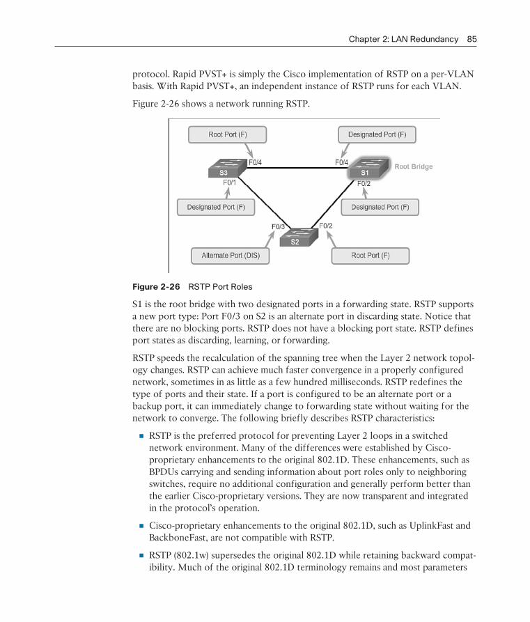
Chapter 2: LAN Redundancy 85
protocol. Rapid PVST+ is simply the Cisco implementation of RSTP on a per-VLAN basis. With Rapid PVST+, an independent instance of RSTP runs for each VLAN.
Figure 2-26 shows a network running RSTP.
Figure 2-26 RSTP Port Roles
S1 is the root bridge with two designated ports in a forwarding state. RSTP supports a new port type: Port F0/3 on S2 is an alternate port in discarding state. Notice that there are no blocking ports. RSTP does not have a blocking port state. RSTP defines port states as discarding, learning, or forwarding.
RSTP speeds the recalculation of the spanning tree when the Layer 2 network topol-ogy changes. RSTP can achieve much faster convergence in a properly configured network, sometimes in as little as a few hundred milliseconds. RSTP redefines the type of ports and their state. If a port is configured to be an alternate port or a backup port, it can immediately change to forwarding state without waiting for the network to converge. The following briefly describes RSTP characteristics:
RSTP is the preferred protocol for preventing Layer 2 loops in a switched network environment. Many of the differences were established by Cisco- proprietary enhancements to the original 802.1D. These enhancements, such as BPDUs carrying and sending information about port roles only to neighboring switches, require no additional configuration and generally perform better than the earlier Cisco-proprietary versions. They are now transparent and integrated in the protocol’s operation.
Cisco-proprietary enhancements to the original 802.1D, such as UplinkFast and BackboneFast, are not compatible with RSTP.
RSTP (802.1w) supersedes the original 802.1D while retaining backward compat-ibility. Much of the original 802.1D terminology remains and most parameters

86 Scaling Networks Companion Guide
are unchanged. In addition, 802.1w is capable of reverting to legacy 802.1D to interoperate with legacy switches on a per-port basis. For example, the RSTP spanning tree algorithm elects a root bridge in exactly the same way as the original 802.1D.
RSTP keeps the same BPDU format as the original IEEE 802.1D, except that the version field is set to 2 to indicate RSTP, and the flags field uses all 8 bits.
RSTP is able to actively confirm that a port can safely transition to the forward-ing state without having to rely on any timer configuration.
RSTP BPDU (2.2.3.2)
RSTP uses type 2, version 2 BPDUs. The original 802.1D STP uses type 0, version 0 BPDUs. However, a switch running RSTP can communicate directly with a switch running the original 802.1D STP. RSTP sends BPDUs and populates the flag byte in a slightly different manner than in the original 802.1D:
Protocol information can be immediately aged on a port if Hello packets are not received for three consecutive Hello times, six seconds by default, or if the max age timer expires.
Because BPDUs are used as a keepalive mechanism, three consecutively missed BPDUs indicate lost connectivity between a bridge and its neighboring root or designated bridge. The fast aging of the information allows failures to be detected quickly.
Note
Like STP, an RSTP switch sends a BPDU with its current information every Hello time period (two seconds, by default), even if the RSTP bridge does not receive any BPDUs from the root bridge.
As shown in Figure 2-27, RSTP uses the flag byte of version 2 BPDU:
Bits 0 and 7 are used for topology change and acknowledgment as they are in the original 802.1D.
Bits 1 and 6 are used for the Proposal Agreement process (used for rapid convergence).
Bits from 2 to 5 encode the role and state of the port.
Bits 4 and 5 are used to encode the port role using a 2-bit code.
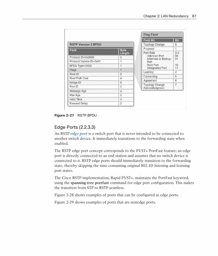
Chapter 2: LAN Redundancy 87
Figure 2-27 RSTP BPDU
Edge Ports (2.2.3.3)
An RSTP edge port is a switch port that is never intended to be connected to another switch device. It immediately transitions to the forwarding state when enabled.
The RSTP edge port concept corresponds to the PVST+ PortFast feature; an edge port is directly connected to an end station and assumes that no switch device is connected to it. RSTP edge ports should immediately transition to the forwarding state, thereby skipping the time-consuming original 802.1D listening and learning port states.
The Cisco RSTP implementation, Rapid PVST+, maintains the PortFast keyword, using the spanning-tree portfast command for edge port configuration. This makes the transition from STP to RSTP seamless.
Figure 2-28 shows examples of ports that can be configured as edge ports.
Figure 2-29 shows examples of ports that are nonedge ports.
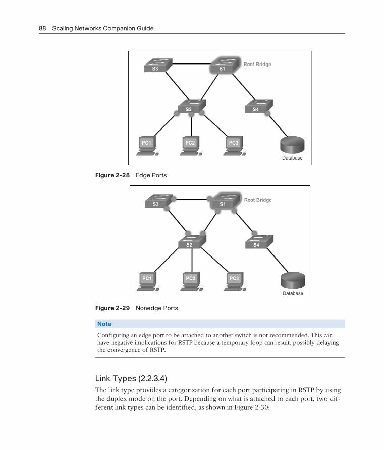
88 Scaling Networks Companion Guide
Figure 2-28 Edge Ports
Figure 2-29 Nonedge Ports
Note
Configuring an edge port to be attached to another switch is not recommended. This can have negative implications for RSTP because a temporary loop can result, possibly delaying the convergence of RSTP.
Link Types (2.2.3.4)
The link type provides a categorization for each port participating in RSTP by using the duplex mode on the port. Depending on what is attached to each port, two dif-ferent link types can be identified, as shown in Figure 2-30:

Chapter 2: LAN Redundancy 89
Point-to-Point Link
Shared Link
Figure 2-30 RSTP Link Types
Point-to-Point Link: A port operating in full-duplex mode typically connects a switch to a switch and is a candidate for rapid transition to a forwarding state.
Shared Link: A port operating in half-duplex mode connects a switch to a hub that attaches multiple devices.
The link type can determine whether the port can immediately transition to a for-warding state, assuming that certain conditions are met. These conditions are differ-ent for edge ports and nonedge ports. Nonedge ports are categorized into two link types, point-to-point and shared. The link type is automatically determined, but can be overridden with an explicit port configuration using the spanning-tree link-type parameter command.
Edge port connections and point-to-point connections are candidates for rapid tran-sition to the forwarding state. However, before the link-type parameter is consid-ered, RSTP must determine the port role. Characteristics of port roles with regard to link types include the following:
Root ports do not use the link-type parameter. Root ports are able to make a rapid transition to the forwarding state as soon as the port is in sync.
Alternate and backup ports do not use the link-type parameter in most cases.
Designated ports make the most use of the link-type parameter. Rapid transi-tion to the forwarding state for the designated port occurs only if the link-type parameter is set to point-to-point.

90 Scaling Networks Companion Guide
Activity 2.2.3.5: Identify Port Roles in Rapid PVST+
Go to the course online to perform this practice activity.
Activity 2.2.3.6: Compare PVST+ and Rapid PVST+
Go to the course online to perform this practice activity.
Spanning Tree Configuration (2.3)Although STP runs by default, there are some configurations that allow the network administrator to modify the version and behavior of STP, including root bridge elec-tion, speeding up convergence, and load balancing.
PVST+ Configuration (2.3.1)
In this topic, we review the commands to modify the default PVST+ configuration.
Catalyst 2960 Default Configuration (2.3.1.1)
Table 2-5 shows the default spanning tree configuration for a Cisco Catalyst 2960 Series switch. Notice that the default spanning tree mode is PVST+.
Table 2-5 Default Switch Configuration
Feature Default Setting
Enable state Enabled on VLAN 1
Spanning-tree mode PVST+
Switch priority 32768
Spanning-tree port priority (configurable on a per-interface basis)
128
Spanning-tree port cost (configurable on a per-interface basis)
1000 Mbps: 4
100 Mbps: 19
10 Mbps: 100
Spanning-tree VLAN port priority (configurable on a per-VLAN basis)
128
InteractiveGraphic
InteractiveGraphic
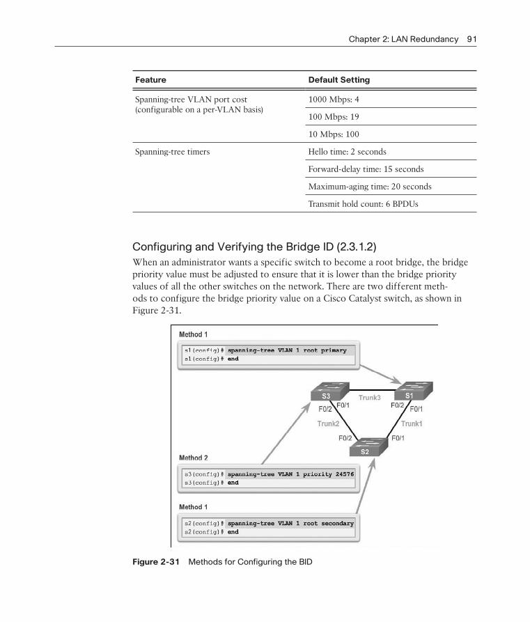
Chapter 2: LAN Redundancy 91
Feature Default Setting
Spanning-tree VLAN port cost (configurable on a per-VLAN basis)
1000 Mbps: 4
100 Mbps: 19
10 Mbps: 100
Spanning-tree timers Hello time: 2 seconds
Forward-delay time: 15 seconds
Maximum-aging time: 20 seconds
Transmit hold count: 6 BPDUs
Configuring and Verifying the Bridge ID (2.3.1.2)
When an administrator wants a specific switch to become a root bridge, the bridge priority value must be adjusted to ensure that it is lower than the bridge priority values of all the other switches on the network. There are two different meth-ods to configure the bridge priority value on a Cisco Catalyst switch, as shown in Figure 2-31.
Figure 2-31 Methods for Configuring the BID

92 Scaling Networks Companion Guide
Method 1To ensure that the switch has the lowest bridge priority value, use the spanning-tree vlan vlan-id root primary command in global configuration mode. The priority for the switch is set to the predefined value of 24,576 or to the highest multiple of 4,096, less than the lowest bridge priority detected on the network.
If an alternate root bridge is desired, use the spanning-tree vlan vlan-id root sec-ondary global configuration mode command. This command sets the priority for the switch to the predefined value of 28,672. This ensures that the alternate switch becomes the root bridge if the primary root bridge fails. This assumes that the rest of the switches in the network have the default 32,768 priority value defined.
In Figure 2-31, S1 has been assigned as the primary root bridge using the spanning-tree vlan 1 root primary command, and S2 has been configured as the secondary root bridge using the spanning-tree vlan 1 root secondary command.
Method 2Another method for configuring the bridge priority value is using the spanning-tree vlan vlan-id priority value global configuration mode command. This command gives more granular control over the bridge priority value. The priority value is con-figured in increments of 4,096 between 0 and 61,440.
In Figure 2-31, S3 has been assigned a bridge priority value of 24,576 using the spanning-tree vlan 1 priority 24576 command.
To verify the bridge priority of a switch, use the show spanning-tree command. In Example 2-3, the priority of the switch has been set to 24,576. Also notice that the switch is designated as the root bridge for the spanning tree instance.
Example 2-3 Verifying That S3 Is the Root Bridge
S3# show spanning-tree
VLAN0001
Spanning tree enabled protocol ieee
Root ID Priority 24577
Address 000A.0033.0033
This bridge is the root
Hello Time 2 sec Max Age 20 sec Forward Delay 15 sec
Bridge ID Priority 24577 (priority 24576 sys-id-ext 1)
Address 000A.0033.3333
Hello Time 2 sec Max Age 20 sec Forward Delay 15 sec
Aging Time 300

Chapter 2: LAN Redundancy 93
Interface Role Sts Cost Prio.Nbr Type
------------------- ---- --- --------- -------- ------------------------
Fa0/1 Desg FWD 4 128.1 P2p
Fa0/2 Desg FWD 4 128.2 P2p
PortFast and BPDU Guard (2.3.1.3)
PortFast is a Cisco feature for PVST+ environments. When a switch port is config-ured with PortFast, that port transitions from blocking to forwarding state imme-diately, bypassing the usual 802.1D STP transition states (the listening and learning states). You can use PortFast on access ports to allow these devices to connect to the network immediately, rather than waiting for IEEE 802.1D STP to converge on each VLAN. Access ports are ports that are connected to a single workstation or to a server, as shown in Figure 2-32.
Figure 2-32 PortFast and BPDU Guard
In a valid PortFast configuration, BPDUs should never be received, because that would indicate that another bridge or switch is connected to the port, potentially causing a spanning tree loop. Cisco switches support a feature called BPDU guard. When it is enabled, BPDU guard puts the port in an error-disabled state on receipt of a BPDU. This will effectively shut down the port. The BPDU guard feature pro-vides a secure response to invalid configurations because you must manually put the interface back into service.

94 Scaling Networks Companion Guide
Cisco PortFast technology is useful for DHCP. Without PortFast, a PC can send a DHCP request before the port is in forwarding state, denying the host from getting a usable IP address and other information. Because PortFast immediately changes the state to forwarding, the PC always gets a usable IP address.
Note
Because the purpose of PortFast is to minimize the time that access ports must wait for span-ning tree to converge, it should only be used on access ports. If you enable PortFast on a port connecting to another switch, you risk creating a spanning tree loop.
To configure PortFast on a switch port, enter the spanning-tree portfast interface configuration mode command on each interface that PortFast is to be enabled. The spanning-tree portfast default global configuration mode command enables Port-Fast on all nontrunking interfaces.
To configure BPDU guard on a Layer 2 access port, use the spanning-tree bpduguard enable interface configuration mode command. The spanning-tree portfast bpduguard default global configuration command enables BPDU guard on all PortFast-enabled ports.
To verify that PortFast and BPDU guard have been enabled for a switch port, use the show running-config command. PortFast and BPDU guard are disabled, by default, on all interfaces.
In Example 2-4, the FastEthernet 0/11 interface is configured with PortFast and BPDU guard.
Example 2-4 Configuring and Verifying PortFast and BPDU Guard
S2(config)# interface FastEthernet 0/11
S2(config-if)# spanning-tree portfast
%Warning: portfast should only be enabled on ports connected to a single
host. Connecting hubs, concentrators, switches, bridges, etc... to this
interface when portfast is enabled, can cause temporary bridging loops.
Use with CAUTION
%Portfast has been configured on FastEthernet0/11 but will only
have effect when the interface is in a non-trunking mode.
S2(config-if)# spanning-tree bpduguard enable
S2(config-if)# end
S2# show running-config interface f0/11
Building configuration...
Current configuration : 90 bytes

Chapter 2: LAN Redundancy 95
!
interface FastEthernet0/11
spanning-tree portfast
spanning-tree bpduguard enable
end
PVST+ Load Balancing (2.3.1.4)
The topology in Figure 2-33 shows three switches with 802.1Q trunks connecting them.
Figure 2-33 Configure PVST+
There are two VLANs, 10 and 20, that are being trunked across these links. The goal is to configure S3 as the root bridge for VLAN 20 and S1 as the root bridge for VLAN 10. Port F0/3 on S2 is the forwarding port for VLAN 20 and the block-ing port for VLAN 10. Port F0/2 on S2 is the forwarding port for VLAN 10 and the blocking port for VLAN 20.
In addition to establishing a root bridge, it is also possible to establish a secondary root bridge. A secondary root bridge is a switch that can become the root bridge for a VLAN if the primary root bridge fails. Assuming that the other bridges in the VLAN retain their default STP priority, this switch becomes the root bridge if the primary root bridge fails.
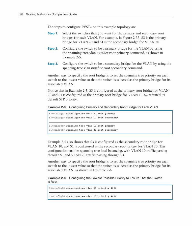
96 Scaling Networks Companion Guide
The steps to configure PVST+ on this example topology are
Step 1. Select the switches that you want for the primary and secondary root bridges for each VLAN. For example, in Figure 2-33, S3 is the primary bridge for VLAN 20 and S1 is the secondary bridge for VLAN 20.
Step 2. Configure the switch to be a primary bridge for the VLAN by using the spanning-tree vlan number root primary command, as shown in Example 2-5.
Step 3. Configure the switch to be a secondary bridge for the VLAN by using the spanning-tree vlan number root secondary command.
Another way to specify the root bridge is to set the spanning tree priority on each switch to the lowest value so that the switch is selected as the primary bridge for its associated VLAN.
Notice that in Example 2-5, S3 is configured as the primary root bridge for VLAN 20 and S1 is configured as the primary root bridge for VLAN 10. S2 retained its default STP priority.
Example 2-5 Configuring Primary and Secondary Root Bridge for Each VLAN
S3(config)# spanning-tree vlan 20 root primary
S3(config)# spanning-tree vlan 10 root secondary
S1(config)# spanning-tree vlan 10 root primary
S1(config)# spanning-tree vlan 20 root secondary
Example 2-5 also shows that S3 is configured as the secondary root bridge for VLAN 10, and S1 is configured as the secondary root bridge for VLAN 20. This configuration enables spanning tree load balancing, with VLAN 10 traffic passing through S1 and VLAN 20 traffic passing through S3.
Another way to specify the root bridge is to set the spanning tree priority on each switch to the lowest value so that the switch is selected as the primary bridge for its associated VLAN, as shown in Example 2-6.
Example 2-6 Configuring the Lowest Possible Priority to Ensure That the Switch
Is Root
S3(config)# spanning-tree vlan 20 priority 4096
S3(config)# spanning-tree vlan 20 priority 4096

Chapter 2: LAN Redundancy 97
The switch priority can be set for any spanning tree instance. This setting affects the likelihood that a switch is selected as the root bridge. A lower value increases the probability that the switch is selected. The range is 0 to 61,440 in increments of 4,096; all other values are rejected. For example, a valid priority value is 4,096 x 2 = 8,192.
As shown in Example 2-7, the show spanning-tree active command displays span-ning tree configuration details for the active interfaces only.
Example 2-7 Verifying STP Active Interfaces
S1# show spanning-tree active
<output omitted>
VLAN0010
Spanning tree enabled protocol ieee
Root ID Priority 4106
Address ec44.7631.3880
This bridge is the root
Hello Time 2 sec Max Age 20 sec Forward Delay 15 sec
Bridge ID Priority 4106 (priority 4096 sys-id-ext 10)
Address ec44.7631.3880
Hello Time 2 sec Max Age 20 sec Forward Delay 15 sec
Aging Time 300 sec
Interface Role Sts Cost Prio.Nbr Type
------------------- ---- --- --------- -------- --------------------------------
Fa0/3 Desg FWD 19 128.5 P2p
Fa0/4 Desg FWD 19 128.6 P2p
The output shown is for S1 configured with PVST+. There are a number of Cisco IOS command parameters associated with the show spanning-tree command.
In Example 2-8, the output shows that the priority for VLAN 10 is 4,096, the lowest of the three respective VLAN priorities.
Example 2-8 Verifying the S1 STP Configuration
S1# show running-config | include span
spanning-tree mode pvst
spanning-tree extend system-id
spanning-tree vlan 1 priority 24576
spanning-tree vlan 10 priority 4096
spanning-tree vlan 20 priority 28672

98 Scaling Networks Companion Guide
Packet Tracer 2.3.1.5: Configuring PVST+
In this activity, you will configure VLANs and trunks, and examine and configure the Spanning Tree Protocol primary and secondary root bridges. You will also opti-mize the switched topology using PVST+, PortFast, and BPDU guard.
Rapid PVST+ Configuration (2.3.2)
Because PVST+ is the default STP mode, Rapid PVST+ must be explicitly configured.
Spanning Tree Mode (2.3.2.1)
Rapid PVST+ is the Cisco implementation of RSTP. It supports RSTP on a per-VLAN basis. The topology in Figure 2-34 has two VLANs: 10 and 20.
Figure 2-34 Configure Rapid PVST+
Note
The default spanning tree configuration on a Catalyst 2960 Series switch is PVST+. A Cata-lyst 2960 switch supports PVST+, Rapid PVST+, and MST, but only one version can be active for all VLANs at any time.
Rapid PVST+ commands control the configuration of VLAN spanning tree instances. A spanning tree instance is created when an interface is assigned to a VLAN and is
Packet Tracer Activity
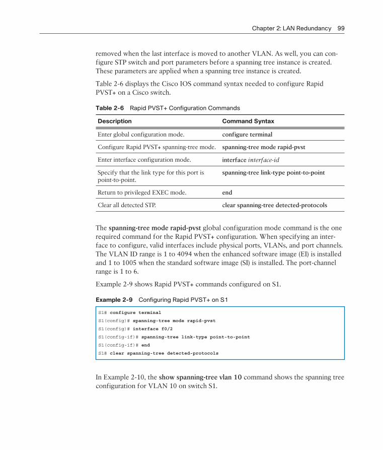
Chapter 2: LAN Redundancy 99
removed when the last interface is moved to another VLAN. As well, you can con-figure STP switch and port parameters before a spanning tree instance is created. These parameters are applied when a spanning tree instance is created.
Table 2-6 displays the Cisco IOS command syntax needed to configure Rapid PVST+ on a Cisco switch.
Table 2-6 Rapid PVST+ Configuration Commands
Description Command Syntax
Enter global configuration mode. configure terminal
Configure Rapid PVST+ spanning-tree mode. spanning-tree mode rapid-pvst
Enter interface configuration mode. interface interface-id
Specify that the link type for this port is point-to-point.
spanning-tree link-type point-to-point
Return to privileged EXEC mode. end
Clear all detected STP. clear spanning-tree detected-protocols
The spanning-tree mode rapid-pvst global configuration mode command is the one required command for the Rapid PVST+ configuration. When specifying an inter-face to configure, valid interfaces include physical ports, VLANs, and port channels. The VLAN ID range is 1 to 4094 when the enhanced software image (EI) is installed and 1 to 1005 when the standard software image (SI) is installed. The port-channel range is 1 to 6.
Example 2-9 shows Rapid PVST+ commands configured on S1.
Example 2-9 Configuring Rapid PVST+ on S1
S1# configure terminal
S1(config)# spanning-tree mode rapid-pvst
S1(config)# interface f0/2
S1(config-if)# spanning-tree link-type point-to-point
S1(config-if)# end
S1# clear spanning-tree detected-protocols
In Example 2-10, the show spanning-tree vlan 10 command shows the spanning tree configuration for VLAN 10 on switch S1.

100 Scaling Networks Companion Guide
Example 2-10 Verifying That VLAN 10 Is Using RSTP
S1# show spanning-tree vlan 10
VLAN0010
Spanning tree enabled protocol rstp
Root ID Priority 4106
Address ec44.7631.3880
This bridge is the root
Hello Time 2 sec Max Age 20 sec Forward Delay 15 sec
Bridge ID Priority 4106 (priority 4096 sys-id-ext 10)
Address ec44.7631.3880
Hello Time 2 sec Max Age 20 sec Forward Delay 15 sec
Aging Time 300 sec
Interface Role Sts Cost Prio.Nbr Type
------------------- ---- --- --------- -------- --------------------------------
Fa0/3 Desg FWD 19 128.5 P2p Peer(STP)
Fa0/4 Desg FWD 19 128.6 P2p Peer(STP)
Notice that the BID priority is set to 4,096. In the output, the statement “Spanning tree enabled protocol rstp” indicates that S1 is running Rapid PVST+. Because S1 is the root bridge for VLAN 10, all of its interfaces are designated ports.
In Example 2-11, the show running-config command is used to verify the Rapid PVST+ configuration on S1.
Example 2-11 Verifying the Rapid PVST+ Configuration
S1# show running-config | include span
spanning-tree mode rapid-pvst
spanning-tree extend system-id
spanning-tree vlan 1 priority 24576
spanning-tree vlan 10 priority 4096
spanning-tree vlan 20 priority 28672
spanning-tree link-type point-to-point
Note
Generally, it is unnecessary to configure the point-to-point link-type parameter for Rapid PVST+, because it is unusual to have a shared link-type. In most cases, the only differ-ence between configuring PVST+ and Rapid PVST+ is the spanning-tree mode rapid-pvst command.

Chapter 2: LAN Redundancy 101
Packet Tracer 2.3.2.2: Configuring Rapid PVST+
In this activity, you will configure VLANs and trunks, and examine and configure the Spanning Tree primary and secondary root bridges. You will also optimize them by using rapid PVST+, PortFast, and BPDU guard.
Lab 2.3.2.3: Configuring Rapid PVST+, PortFast, and BPDU Guard
In this lab, you will complete the following objectives:
Part 1: Build the Network and Configure Basic Device Settings
Part 2: Configure VLANs, Native VLAN, and Trunks
Part 3: Configure the Root Bridge and Examine PVST+ Convergence
Part 4: Configure Rapid PVST+, PortFast, BPDU Guard, and Examine Convergence
STP Configuration Issues (2.3.3)
If STP configuration is left unchanged, the algorithm might not choose the best root bridge. So it is usually desirable to change the configuration. This topic reviews some of the common issues that can occur when the STP configuration is modified.
Analyzing the STP Topology (2.3.3.1)
To analyze the STP topology, follow these steps as shown in Figure 2-35:
Step 1. Discover the Layer 2 topology. Use network documentation if it exists or use the show cdp neighbors command to discover the Layer 2 topology.
Step 2. After discovering the Layer 2 topology, use STP knowledge to determine the expected Layer 2 path. It is necessary to know which switch is the root bridge.
Step 3. Use the show spanning-tree vlan command to determine which switch is the root bridge.
Step 4. Use the show spanning-tree vlan command on all switches to find out which ports are in the blocking or forwarding state and confirm your expected Layer 2 path.
Packet Tracer Activity

102 Scaling Networks Companion Guide
Figure 2-35 Analyzing the STP Topology
Expected Topology Versus Actual Topology (2.3.3.2)
In many networks, the optimal STP topology is determined as part of the network design and then implemented through manipulation of STP priority and cost values. Situations can occur where STP was not considered in the network design and imple-mentation, or where it was considered or implemented before the network under-went significant growth and change. In such situations, it is important to know how to analyze the actual STP topology in the operational network.
A big part of troubleshooting consists of comparing the actual state of the network against the expected state of the network and spotting the differences to gather clues about the troubleshooting problem. A network professional should be able to examine the switches and determine the actual topology, and be able to understand what the underlying spanning tree topology should be.
Overview of Spanning Tree Status (2.3.3.3)
Using the show spanning-tree command without specifying any additional options provides a quick overview of the status of STP for all VLANs that are defined on a switch. If interested only in a particular VLAN, limit the scope of this command by specifying that VLAN as an option.

Chapter 2: LAN Redundancy 103
Use the show spanning-tree vlan vlan_id command to get STP information for a particular VLAN. Use this command to get information about the role and status of each port on the switch. In Figure 2-36, the example output on switch S1 shows all three ports in the forwarding (FWD) state and the role of the three ports as either designated ports or root ports. Any ports being blocked display the output status as “BLK.”
Figure 2-36 show spanning-tree vlan vlan_id Command
The output also gives information about the BID of the local switch and the root ID, which is the BID of the root bridge.
Spanning Tree Failure Consequences (2.3.3.4)
With many protocols, a malfunction means that you lose the functionality that the protocol was providing. For example, if OSPF malfunctions on a router, connectiv-ity to networks that are reachable through that router might be lost. This would generally not affect the rest of the OSPF network. If connectivity to the router is still available, it is possible to troubleshoot to diagnose and fix the problem.
With STP, there are two types of failure. The first is similar to the OSPF problem; STP might erroneously block ports that should have gone into the forwarding state. Connectivity might be lost for traffic that would normally pass through this switch, but the rest of the network remains unaffected. The second type of failure is much
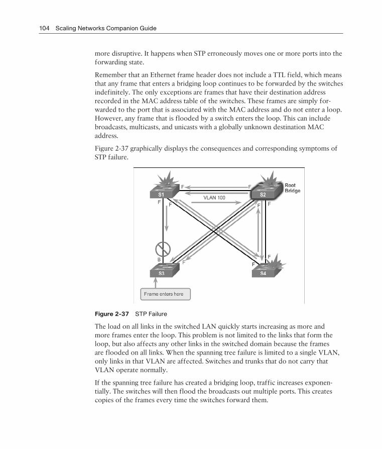
104 Scaling Networks Companion Guide
more disruptive. It happens when STP erroneously moves one or more ports into the forwarding state.
Remember that an Ethernet frame header does not include a TTL field, which means that any frame that enters a bridging loop continues to be forwarded by the switches indefinitely. The only exceptions are frames that have their destination address recorded in the MAC address table of the switches. These frames are simply for-warded to the port that is associated with the MAC address and do not enter a loop. However, any frame that is flooded by a switch enters the loop. This can include broadcasts, multicasts, and unicasts with a globally unknown destination MAC address.
Figure 2-37 graphically displays the consequences and corresponding symptoms of STP failure.
Figure 2-37 STP Failure
The load on all links in the switched LAN quickly starts increasing as more and more frames enter the loop. This problem is not limited to the links that form the loop, but also affects any other links in the switched domain because the frames are flooded on all links. When the spanning tree failure is limited to a single VLAN, only links in that VLAN are affected. Switches and trunks that do not carry that VLAN operate normally.
If the spanning tree failure has created a bridging loop, traffic increases exponen-tially. The switches will then flood the broadcasts out multiple ports. This creates copies of the frames every time the switches forward them.

Chapter 2: LAN Redundancy 105
When control plane traffic starts entering the loop (for example, OSPF Hellos or EIGRP Hellos), the devices that are running these protocols quickly start getting overloaded. Their CPUs approach 100 percent utilization while they are trying to process an ever-increasing load of control plane traffic. In many cases, the earliest indication of this broadcast storm in progress is that routers or Layer 3 switches are reporting control plane failures and that they are running at a high CPU load.
The switches experience frequent MAC address table changes. If a loop exists, a switch might see a frame with a certain source MAC address coming in on one port and then see another frame with the same source MAC address coming in on a dif-ferent port a fraction of a second later. This will cause the switch to update the MAC address table twice for the same MAC address.
Because of the combination of very high load on all links and the switch CPUs run-ning at maximum load, these devices typically become unreachable. This makes it very difficult to diagnose the problem while it is happening.
Repairing a Spanning Tree Problem (2.3.3.5)
One way to correct spanning tree failure is to manually remove redundant links in the switched network, either physically or through configuration, until all loops are eliminated from the topology. When the loops are broken, the traffic and CPU loads should quickly drop to normal levels, and connectivity to devices should be restored.
Although this intervention restores connectivity to the network, it is not the end of the troubleshooting process. All redundancy from the switched network has been removed, and now the redundant links must be restored.
If the underlying cause of the spanning tree failure has not been fixed, chances are that restoring the redundant links will trigger a new broadcast storm. Before restor-ing the redundant links, determine and correct the cause of the spanning tree failure. Carefully monitor the network to ensure that the problem is fixed.
Activity 2.3.3.6: Troubleshoot STP Configuration Issues
Go to the course online to perform this practice activity.
First Hop Redundancy Protocols (2.4)The term First Hop Redundancy Protocol (FHRP) refers to a collection of protocols that transparently provide end users with at least one redundant default gateway.
InteractiveGraphic

106 Scaling Networks Companion Guide
Concept of First Hop Redundancy Protocols (2.4.1)
With redundant routers and redundant links, it is possible to configure a redundant default gateway.
Default Gateway Limitations (2.4.1.1)
Spanning tree protocols enable physical redundancy in a switched network. How-ever, a host at the access layer of a hierarchical network also benefits from alternate default gateways. If a router or router interface (that serves as a default gateway) fails, the hosts configured with that default gateway are isolated from outside net-works. A mechanism is needed to provide alternate default gateways in switched networks where two or more routers are connected to the same VLANs.
Note
For the purposes of the discussion on router redundancy, there is no functional difference between a multilayer switch and a router at the distribution layer. In practice, it is common for a multilayer switch to act as the default gateway for each VLAN in a switched network. This discussion focuses on the functionality of routing, regardless of the physical device used.
In a switched network, each client receives only one default gateway. There is no way to configure a secondary gateway, even if a second path exists to carry packets off the local segment.
In Figure 2-38, R1 is responsible for routing packets from PC1.
If R1 becomes unavailable, the routing protocols can dynamically converge. R2 now routes packets from outside networks that would have gone through R1. However, traffic from the inside network associated with R1, including traffic from worksta-tions, servers, and printers configured with R1 as their default gateway, is still sent to R1 and dropped.
End devices are typically configured with a single IP address for a default gateway. This address does not change when the network topology changes. If that default gateway IP address cannot be reached, the local device is unable to send packets off the local network segment, effectively disconnecting it from the rest of the network. Even if a redundant router exists that could serve as a default gateway for that seg-ment, there is no dynamic method by which these devices can determine the address of a new default gateway.

Chapter 2: LAN Redundancy 107
Figure 2-38 Default Gateway Limitations
Router Redundancy (2.4.1.2)
One way to prevent a single point of failure at the default gateway is to implement a virtual router. To implement this type of router redundancy, multiple routers are configured to work together to present the illusion of a single router to the hosts on the LAN, as shown in Figure 2-39. By sharing an IP address and a MAC address, two or more routers can act as a single virtual router.
The IP address of the virtual router is configured as the default gateway for the workstations on a specific IP segment. When frames are sent from host devices to the default gateway, the hosts use ARP to resolve the MAC address that is associ-ated with the IP address of the default gateway. The ARP resolution returns the MAC address of the virtual router. Frames that are sent to the MAC address of the virtual router can then be physically processed by the currently active router within the virtual router group. A protocol is used to identify two or more routers as the devices that are responsible for processing frames that are sent to the MAC or IP address of a single virtual router. Host devices send traffic to the address of the virtual router. The physical router that forwards this traffic is transparent to the host devices.
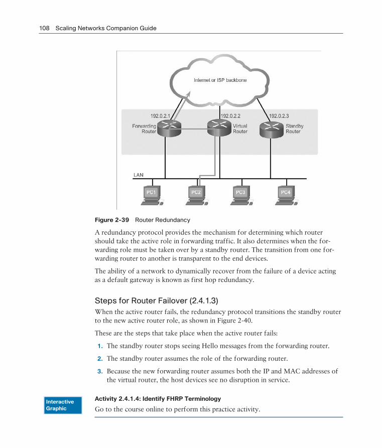
108 Scaling Networks Companion Guide
Figure 2-39 Router Redundancy
A redundancy protocol provides the mechanism for determining which router should take the active role in forwarding traffic. It also determines when the for-warding role must be taken over by a standby router. The transition from one for-warding router to another is transparent to the end devices.
The ability of a network to dynamically recover from the failure of a device acting as a default gateway is known as first hop redundancy.
Steps for Router Failover (2.4.1.3)
When the active router fails, the redundancy protocol transitions the standby router to the new active router role, as shown in Figure 2-40.
These are the steps that take place when the active router fails:
1. The standby router stops seeing Hello messages from the forwarding router.
2. The standby router assumes the role of the forwarding router.
3. Because the new forwarding router assumes both the IP and MAC addresses of the virtual router, the host devices see no disruption in service.
Activity 2.4.1.4: Identify FHRP Terminology
Go to the course online to perform this practice activity.InteractiveGraphic

Chapter 2: LAN Redundancy 109
Figure 2-40 Router Failover Example
Varieties of First Hop Redundancy Protocols (2.4.2)
There are several options to choose from when configuring an FHRP.
First Hop Redundancy Protocols (2.4.2.1)
The following list defines the options available for First Hop Redundancy Protocols (FHRP).
Hot Standby Router Protocol (HSRP): A Cisco-proprietary FHRP designed to allow for transparent failover of a first hop IPv4 device. HSRP provides high network availability by providing first-hop routing redundancy for IPv4 hosts on networks configured with an IPv4 default gateway address. HSRP is used in a group of routers for selecting an active device and a standby device. In a group of device interfaces, the active device is the device that is used for routing pack-ets; the standby device is the device that takes over when the active device fails, or when preset conditions are met. The function of the HSRP standby router is to monitor the operational status of the HSRP group and to quickly assume packet-forwarding responsibility if the active router fails.
HSRP for IPv6: A Cisco-proprietary FHRP providing the same functionality of HSRP, but in an IPv6 environment. An HSRP IPv6 group has a virtual MAC

110 Scaling Networks Companion Guide
address derived from the HSRP group number and a virtual IPv6 link-local address derived from the HSRP virtual MAC address. Periodic router advertise-ments (RA) are sent for the HSRP virtual IPv6 link-local address when the HSRP group is active. When the group becomes inactive, these RAs stop after a final RA is sent.
Virtual Router Redundancy Protocol version 2 (VRRPv2): A nonproprietary election protocol that dynamically assigns responsibility for one or more virtual routers to the VRRP routers on an IPv4 LAN. This allows several routers on a multiaccess link to use the same virtual IPv4 address. A VRRP router is config-ured to run the VRRP protocol in conjunction with one or more other routers attached to a LAN. In a VRRP configuration, one router is elected as the virtual router master, with the other routers acting as backups, in case the virtual router master fails.
VRRPv3: Provides the capability to support IPv4 and IPv6 addresses. VRRPv3 works in multivendor environments and is more scalable than VRRPv2.
Gateway Load Balancing Protocol (GLBP): A Cisco-proprietary FHRP that protects data traffic from a failed router or circuit, like HSRP and VRRP, while also allowing load balancing (also called load sharing) between a group of redun-dant routers.
GLBP for IPv6: A Cisco-proprietary FHRP providing the same functionality of GLBP, but in an IPv6 environment. GLBP for IPv6 provides automatic router backup for IPv6 hosts configured with a single default gateway on a LAN. Mul-tiple first-hop routers on the LAN combine to offer a single virtual first-hop IPv6 router while sharing the IPv6 packet-forwarding load.
ICMP Router Discovery Protocol (IRDP): Specified in RFC 1256, this is a leg-acy FHRP solution. IRDP allows IPv4 hosts to locate routers that provide IPv4 connectivity to other (nonlocal) IP networks.
Activity 2.4.2.2: Identify the Type of FHRP
Go to the course online to perform this practice activity.
FHRP Verification (2.4.3)
This topic briefly reviews the tasks necessary to configure and verify HSRP and GLBP.
HSRP Verification (2.4.3.1)
Figure 2-41 shows an example topology for configuring either HSRP or GLBP.
InteractiveGraphic

Chapter 2: LAN Redundancy 111
Figure 2-41 FHRP Configuration Topology
An HSRP active router has the following characteristics:
Responds to default gateway’s ARP requests with the virtual router’s MAC.
Assumes active forwarding of packets for the virtual router.
Sends Hello messages.
Knows the virtual router IP address.
An HSRP standby router has the following characteristics:
Listens for periodic Hello messages.
Assumes active forwarding of packets if it does not hear from the active router.
Use the show standby command to verify the HSRP state. In Example 2-12, the output shows that R1 is in the active state.
Example 2-12 Verifying That R1 Is the HSRP Active Router
R1# show standby
FastEthernet0/1 - Group 10
State is Active
2 state changes, last state change 00:04:01
Virtual IP address is 172.16.10.1
Active virtual MAC address is 0000.0c07.ac0a
Local virtual MAC address is 0000.0c07.ac0a (v1 default)
Hello time 3 sec, hold time 10 sec
Next hello sent in 0.528 secs
Preemption disabled
Active router is local
Standby router is 172.16.10.3, priority 110 (expires in 10.576 sec)
Priority 150 (configured 150)
Group name is "hsrp-Fa0/1-10" (default)
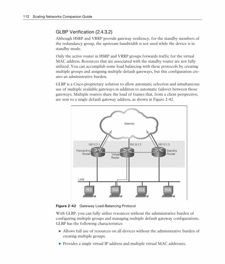
112 Scaling Networks Companion Guide
GLBP Verification (2.4.3.2)
Although HSRP and VRRP provide gateway resiliency, for the standby members of the redundancy group, the upstream bandwidth is not used while the device is in standby mode.
Only the active router in HSRP and VRRP groups forwards traffic for the virtual MAC address. Resources that are associated with the standby router are not fully utilized. You can accomplish some load balancing with these protocols by creating multiple groups and assigning multiple default gateways, but this configuration cre-ates an administrative burden.
GLBP is a Cisco-proprietary solution to allow automatic selection and simultaneous use of multiple available gateways in addition to automatic failover between those gateways. Multiple routers share the load of frames that, from a client perspective, are sent to a single default gateway address, as shown in Figure 2-42.
Figure 2-42 Gateway Load-Balancing Protocol
With GLBP, you can fully utilize resources without the administrative burden of configuring multiple groups and managing multiple default gateway configurations. GLBP has the following characteristics:
Allows full use of resources on all devices without the administrative burden of creating multiple groups.
Provides a single virtual IP address and multiple virtual MAC addresses.

Chapter 2: LAN Redundancy 113
Routes traffic to single gateway distributed across routers.
Provides automatic rerouting in the event of any failure.
Use the show glbp command to verify the GLBP status. Example 2-13 for R1 shows that GLBP group 10 is in the active state with virtual IP address 172.16.10.1. R1 is the active router for Forwarder 2.
Example 2-13 Verifying R1 GLBP Forwarding Roles
R1# show glbp
FastEthernet0/1 - Group 10
State is Active
2 state changes, last state change 00:02:50
Virtual IP address is 172.16.10.1
Hello time 3 sec, hold time 10 sec
Next hello sent in 1.408 secs
Redirect time 600 sec, forwarder timeout 14400 sec
Preemption disabled
Active is local
Standby is 172.16.10.3, priority 110 (expires in 7.776 sec)
Priority 150 (configured)
Weighting 100 (default 100), thresholds: lower 1, upper 100
Load balancing: round-robin
Group members:
0016.c8ee.131a (172.16.10.3)
001b.d4ef.5091 (172.16.10.2) local
There are 2 forwarders (1 active)
Forwarder 1
State is Listen
2 state changes, last state change 00:00:09
MAC address is 0007.b400.0a01 (learnt)
Owner ID is 0016.c8ee.131a
Redirection enabled, 597.792 sec remaining (maximum 600 sec)
Time to live: 14397.792 sec (maximum 14400 sec)
Preemption enabled, min delay 30 sec
Active is 172.16.10.3 (primary), weighting 100 (expires in 9.920 sec)
Forwarder 2
State is Active
1 state change, last state change 00:05:57
MAC address is 0007.b400.0a02 (default)
Owner ID is 001b.d4ef.5091
Redirection enabled
Preemption enabled, min delay 30 sec
Active is local, weighting 100

114 Scaling Networks Companion Guide
Syntax Checker — HSRP and GLBP (2.4.3.3)
Configuration of HSRP and GLBP is beyond the scope of this course. However, familiarity with the commands used to enable HSRP and GLBP aid in understanding the configuration output. For this reason, the syntax checker and subsequent lab are available as optional exercises.
Lab 2.4.3.4: Configuring HSRP and GLBP
In this lab, you will complete the following objectives:
Part 1: Build the Network and Verify Connectivity
Part 2: Configure First Hop Redundancy Using HSRP
Part 3: Configure First Hop Redundancy Using GLBP

Chapter 2: LAN Redundancy 115
Summary (2.5)
Class Activity 2.5.1.1: Documentation Tree
The employees in your building are having difficulty accessing a web server on the network. You look for the network documentation that the previous network engi-neer used before he transitioned to a new job; however, you cannot find any net-work documentation whatsoever.
Therefore, you decide to create your own network record-keeping system. You decide to start at the access layer of your network hierarchy. This is where redun-dant switches are located, as well as the company servers, printers, and local hosts.
You create a matrix to record your documentation and include access layer switches on the list. You also decide to document switch names, ports in use, cabling connec-tions, root ports, designated ports, and alternate ports.
Problems that can result from a redundant Layer 2 network include broadcast storms, MAC database instability, and duplicate unicast frames. STP is a Layer 2 protocol that ensures that there is only one logical path between all destinations on the network by intentionally blocking redundant paths that could cause a loop.
STP sends BPDU frames for communication between switches. One switch is elected as the root bridge for each instance of spanning tree. An administrator can control this election by changing the bridge priority. Root bridges can be configured to enable spanning tree load balancing by VLAN or by a group of VLANs, depending on the spanning tree protocol used. STP then assigns a port role to each participat-ing port using a path cost. The path cost is equal to the sum of all the port costs along the path to the root bridge. A port cost is automatically assigned to each port; however, it can also be manually configured. Paths with the lowest cost become preferred, and all other redundant paths are blocked.
PVST+ is the default configuration of IEEE 802.1D on Cisco switches. It runs one instance of STP for each VLAN. A newer, faster-converging spanning tree protocol, RSTP, can be implemented on Cisco switches on a per-VLAN basis in the form of Rapid PVST+. Multiple Spanning Tree (MST) is the Cisco implementation of Mul-tiple Spanning Tree Protocol (MSTP), where one instance of spanning tree runs for a defined group of VLANs. Features such as PortFast and BPDU guard ensure that hosts in the switched environment are provided immediate access to the network without interfering with spanning tree operation.
First Hop Redundancy Protocols, such as HSRP, VRRP, and GLBP, provide alternate default gateways for hosts in the redundant router or multilayer switched environ-ment. Multiple routers share a virtual IP address and MAC address that is used as
116 Scaling Networks Companion Guide
the default gateway on a client. This ensures that hosts maintain connectivity in the event of the failure of one device serving as a default gateway for a VLAN or set of VLANs. When using HSRP or VRRP, one router is active or forwarding for a par-ticular group while others are in standby mode. GLBP allows the simultaneous use of multiple gateways in addition to providing automatic failover.
PracticeThe following activities provide practice with the topics introduced in this chapter. The Labs and Class Activities are available in the companion Scaling Networks Lab
Manual (ISBN 978-1-58713-325-1). The Packet Tracer Activities PKA files are found in the online course.
Class Activities
Class Activity 2.0.1.2: Stormy Traffic
Class Activity 2.5.1.1: Documentation Tree
Labs
Lab 2.1.2.10: Building a Switched Network with Redundant Links
Lab 2.3.2.3: Configuring Rapid PVST+, PortFast, and BPDU Guard
Lab 2.4.3.4: Configuring HSRP and GLBP
Packet Tracer Activities
Packet Tracer Activity 2.1.1.5: Examining a Redundant Design
Packet Tracer Activity 2.3.1.5: Configuring PVST+
Packet Tracer Activity 2.3.2.2: Configuring Rapid PVST+
Packet Tracer Activity

Chapter 2: LAN Redundancy 117
Check Your Understanding QuestionsComplete all the review questions listed here to test your understanding of the topics and concepts in this chapter. The appendix “Answers to ‘Check Your Understanding’ Questions” lists the answers.
1. What is an accurate description of redundancy?
A. Configuring a router with a complete MAC address database to ensure that all frames can be forwarded to the correct destination
B. Designing a network to use multiple paths between switches to ensure that there is no single point of failure
C. Designing a network to use multiple virtual devices to ensure that all traffic uses the best path through the internetwork
D. Configuring a switch with proper security to ensure that all traffic forwarded through an interface is filtered
2. Which of the following issues are the result of a broadcast storm? (Choose two.)
A. During a broadcast storm, constant changes to the MAC address table pre-vent a switch from accurately forwarding frames.
B. In a network saturated with broadcast traffic, new traffic arriving at the switch will be forwarded into the broadcast domain, which further consumes available bandwidth.
C. During a broadcast storm, switches with high-speed interfaces will forward traffic in half-duplex mode to conserve available bandwidth.
D. Because of high processing demands during a broadcast storm, communica-tion can fail between end stations in the broadcast domain.
E. During a broadcast storm, a switch will forward a received broadcast out every port on the switch.
3. During the implementation of Spanning Tree Protocol, all switches are rebooted by the network administrator. What is the first step of the spanning-tree election process?
A. Each switch determines the best path to forward traffic.
B. Each switch determines what port to block to prevent a loop from occurring.
C. Each switch with a lower root ID than its neighbor will not send BPDUs.
D. All the switches send out BPDUs advertising themselves as the root bridge.
118 Scaling Networks Companion Guide
4. After the election of the root bridge has been completed, how will switches find the best paths to the root bridge?
A. Each switch will analyze the sum of all port costs to reach the root and use the path with the lowest cost.
B. Each switch will analyze the port states of all neighbors and use the desig-nated ports to forward traffic to the root.
C. Each switch will analyze the sum of the hops to reach the root and use the path with the fewest hops.
D. Each switch will analyze the BID of all neighbors to reach the root and use the path through the lowest BID neighbors.
5. When PVST is running over a switched network, which port state can participate in BPDU frame forwarding based on BPDUs received, but does not forward data frames?
A. Disabled
B. Blocking
C. Listening
D. Forwarding
6. What are expectations of configuring PortFast on a switch port? (Choose two.)
A. The switch port immediately transitions from the listening to the forwarding state.
B. The switch port immediately processes any BPDUs before transitioning to the forwarding state.
C. The switch port sends DHCP requests before transitioning to the forwarding state.
D. The switch port should never receive BPDUs from end stations that are con-nected to the port.
E. The switch port immediately transitions from the blocking to the forwarding state.
7. Which of the following port states are used by Rapid PVST+? (Choose three.)
A. Learning
B. Blocking
C. Trunking
D. Discarding
E. Forwarding
F. Listening

Chapter 2: LAN Redundancy 119
8. An administrator is troubleshooting a switch and wants to verify whether it is a root bridge. What command can be used to do this?
A. show vlan
B. show spanning-tree
C. show running-config
D. show startup-config
9. What is the initial approach that should be used to troubleshoot a broadcast storm in a switched network?
A. Replace all instances of STP with RSTP.
B. Insert redundant links to replace the failed STP links.
C. Manually remove redundant links in the switched network.
D. Replace the cables on failed STP links.
10. When first hop redundancy protocols are used, which of the following items will be shared by a set of routers that are presenting the illusion of being a single router? (Choose two.)
A. Host name
B. BID
C. MAC address
D. IP address
E. Static route
11. A network administrator is overseeing the implementation of first hop redun-dancy protocols. Which of the following protocols will not be able to function with multivendor devices? (Choose two.)
A. VRRP
B. HSRP
C. IRDP
D. GLBP
12. Indicate the STP protocol the matches the description.
is a legacy standard that runs all VLANs in a single spanning tree instance.
is a Cisco enhancement of RSTP that provides a spanning tree instance for each VLAN.
allows multiple VLANs to run in a single spanning tree instance.
13. List the three steps that an FHRP initiates during a router failover process.

This page intentionally left blank
CHAPTER 3
LAN Aggregation
ObjectivesUpon completion of this chapter, you will be able to answer the following questions:
What is link aggregation?
What is EtherChannel technology?
What are the commands to configure EtherChannel?
What are the methods to troubleshoot link aggregation with EtherChannel?
Key TermsThis chapter uses the following key terms. You can find the definitions in the Glossary.
Port Aggregation Protocol (PAgP) page 122
Link Aggregation Control Protocol
(LACP) page 122
PAgP desirable page 127
PAgP auto page 127
LACP active page 129
LACP passive page 129
122 Scaling Networks Companion Guide
Introduction (3.0.1.1)Link aggregation is the ability to create one logical link using multiple physical links between two devices. This allows load sharing among the physical links, rather than having STP block one or more of the links. EtherChannel is a form of link aggrega-tion used in switched networks.
This chapter describes EtherChannel and the methods used to create an Ether-Channel. An EtherChannel can be manually configured or can be negotiated by using the Cisco-proprietary protocol Port Aggregation Protocol (PAgP) or the IEEE 802.3ad–defined protocol Link Aggregation Control Protocol (LACP). The configuration, verification, and troubleshooting of EtherChannel are discussed.
Class Activity 3.0.1.2: Imagine This
It is the end of the work day. In your small- to medium-sized business, you are try-ing to explain to the network engineers about EtherChannel and how it looks when it is physically set up. The network engineers have difficulty envisioning how two switches could possibly be connected through several links that collectively act as one channel or connection. Your company is definitely considering implementing an EtherChannel network.
Therefore, you end the meeting with an assignment for the engineers. To prepare for the next day’s meeting, they are to perform some research and bring to the meeting one graphic representation of an EtherChannel network connection. They are tasked with explaining how an EtherChannel network operates to the other engineers.
When researching EtherChannel, a good question to search for is “What does Ether-Channel look like?” Prepare a few slides to demonstrate your research that will be presented to the network engineering group. These slides should provide a solid grasp of how EtherChannels are physically created within a network topology. Your goal is to ensure that everyone leaving the next meeting will have a good idea as to why he or she would consider moving to a network topology using EtherChannel as an option.
Link Aggregation Concepts (3.1)In this section, we discuss link aggregation and EtherChannel, a Layer 2 link aggrega-tion technology.

Chapter 3: LAN Aggregation 123
Link Aggregation (3.1.1)
Link aggregation is the process of using multiple redundant links as one logical link in order to take advantage of underutilized links to increase bandwidth.
Introduction to Link Aggregation (3.1.1.1)
In Figure 3-1, traffic coming from several links (usually 100 or 1000 Mb/s) aggre-gates on the access switch and must be sent to distribution switches. Because of the traffic aggregation, links with higher bandwidth must be available between the access and distribution switches.
Figure 3-1 Redundant Links with STP
It might be possible to use faster links, such as 10 Gb/s, on the aggregated link between the access and distribution layer switches. However, adding faster links is expensive. Additionally, as the speed increases on the access links, even the fastest possible port on the aggregated link is no longer fast enough to aggregate the traffic coming from all access links.
It is also possible to multiply the number of physical links between the switches to increase the overall speed of switch-to-switch communication. However, by default, STP is enabled on switch devices. STP will block redundant links to prevent routing loops.
For these reasons, the best solution is to implement an EtherChannel configuration.
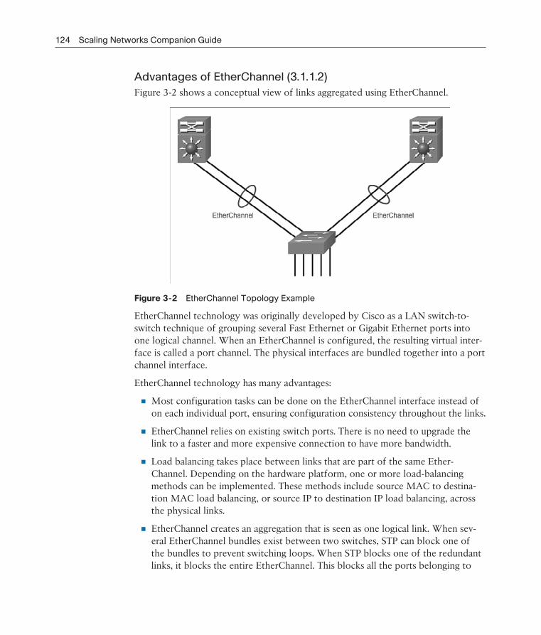
124 Scaling Networks Companion Guide
Advantages of EtherChannel (3.1.1.2)
Figure 3-2 shows a conceptual view of links aggregated using EtherChannel.
Figure 3-2 EtherChannel Topology Example
EtherChannel technology was originally developed by Cisco as a LAN switch-to-switch technique of grouping several Fast Ethernet or Gigabit Ethernet ports into one logical channel. When an EtherChannel is configured, the resulting virtual inter-face is called a port channel. The physical interfaces are bundled together into a port channel interface.
EtherChannel technology has many advantages:
Most configuration tasks can be done on the EtherChannel interface instead of on each individual port, ensuring configuration consistency throughout the links.
EtherChannel relies on existing switch ports. There is no need to upgrade the link to a faster and more expensive connection to have more bandwidth.
Load balancing takes place between links that are part of the same Ether-Channel. Depending on the hardware platform, one or more load-balancing methods can be implemented. These methods include source MAC to destina-tion MAC load balancing, or source IP to destination IP load balancing, across the physical links.
EtherChannel creates an aggregation that is seen as one logical link. When sev-eral EtherChannel bundles exist between two switches, STP can block one of the bundles to prevent switching loops. When STP blocks one of the redundant links, it blocks the entire EtherChannel. This blocks all the ports belonging to

Chapter 3: LAN Aggregation 125
that EtherChannel link. Where there is only one EtherChannel link, all physical links in the EtherChannel are active because STP sees only one (logical) link.
EtherChannel provides redundancy because the overall link is seen as one logi-cal connection. Additionally, the loss of one physical link within the channel does not create a change in the topology; therefore a spanning tree recalculation is not required. Assuming that at least one physical link is present, the Ether-Channel remains functional, even if its overall throughput decreases because of a lost link within the EtherChannel.
EtherChannel Operation (3.1.2)
This section reviews the restrictions to implementing EtherChannel and the two EtherChannel protocols.
Implementation Restrictions (3.1.2.1)
EtherChannel can be implemented by grouping multiple physical ports into one or more logical EtherChannel links.
Note
Interface types cannot be mixed. For example, Fast Ethernet and Gigabit Ethernet cannot be mixed within a single EtherChannel.
The EtherChannel provides full-duplex bandwidth up to 800 Mb/s (Fast Ether-Channel) or 8 Gb/s (Gigabit EtherChannel) between one switch and another switch or host. Currently each EtherChannel can consist of up to eight compatibly con-figured Ethernet ports. The Cisco IOS switch can currently support six Ether-Channels. However, as new IOSs are developed and platforms change, some cards and platforms can support increased numbers of ports within an EtherChannel link, as well as support an increased number of Gigabit EtherChannels. The concept is the same no matter the speeds or number of links that are involved. When configur-ing EtherChannel on switches, be aware of the hardware platform boundaries and specifications.
The original purpose of EtherChannel was to increase speed capability on aggre-gated links between switches. However, this concept was extended as EtherChannel technology became more popular, and now many servers also support link aggre-gation with EtherChannel. EtherChannel creates a one-to-one relationship; that is, one EtherChannel link connects only two devices. An EtherChannel link can be created between two switches, or an EtherChannel link can be created between an EtherChannel-enabled server and a switch. However, traffic cannot be sent to two different switches through the same EtherChannel link.

126 Scaling Networks Companion Guide
The individual EtherChannel group member port configuration must be consistent on both devices. If the physical ports of one side are configured as trunks, the physi-cal ports of the other side must also be configured as trunks within the same native VLAN. Additionally, all ports in each EtherChannel link must be configured as Layer 2 ports.
Note
Layer 3 EtherChannels can be configured on Cisco Catalyst multilayer switches, such as the Catalyst 3560, but these are not explored in this course. A Layer 3 EtherChannel has a single IP address associated with the logical aggregation of switch ports in the EtherChannel.
Each EtherChannel has a logical port channel interface, shown in Figure 3-3. A con-figuration applied to the port channel interface affects all physical interfaces that are assigned to that interface.
Figure 3-3 EtherChannel Logical Groupings
Port Aggregation Protocol (3.1.2.2)
EtherChannels can be formed through negotiation using one of two protocols, PAgP or LACP. These protocols allow ports with similar characteristics to form a channel through dynamic negotiation with adjoining switches.
Note
It is also possible to configure a static or unconditional EtherChannel without PAgP or LACP.

Chapter 3: LAN Aggregation 127
PAgPPAgP is a Cisco-proprietary protocol that aids in the automatic creation of Ether-Channel links, as shown in Figure 3-4.
Figure 3-4 PAgP Topology
When an EtherChannel link is configured using PAgP, PAgP packets are sent between EtherChannel-capable ports to negotiate the forming of a channel. When PAgP identifies matched Ethernet links, it groups the links into an EtherChannel. The EtherChannel is then added to the spanning tree as a single port.
When enabled, PAgP also manages the EtherChannel. PAgP packets are sent every 30 seconds. PAgP checks for configuration consistency and manages link additions and failures between two switches. It ensures that when an EtherChannel is created, all ports have the same type of configuration.
Note
In EtherChannel, it is mandatory that all ports have the same speed, duplex setting, and VLAN information. Any port modification after the creation of the channel also changes all other channel ports.
PAgP helps create the EtherChannel link by detecting the configuration of each side and ensuring that links are compatible so that the EtherChannel link can be enabled when needed.
On: This mode forces the interface to channel without PAgP. Interfaces config-ured in the on mode do not exchange PAgP packets.
PAgP desirable: This PAgP mode places an interface in an active negotiating state in which the interface initiates negotiations with other interfaces by send-ing PAgP packets.
PAgP auto: This PAgP mode places an interface in a passive negotiating state in which the interface responds to the PAgP packets that it receives, but does not initiate PAgP negotiation.
Table 3-1 summarizes the result for PAgP channel establishment based on the con-figuration of each side of a link in Figure 3-4.

128 Scaling Networks Companion Guide
Table 3-1 PAgP Channel Establishment
S1 S2 Established?
On On Yes
Auto/Desirable Desirable Yes
On/Auto/Desirable Not Configured No
On Desirable No
Auto/On Auto No
The modes must be compatible on each side. If one side is configured to be in auto mode, it is placed in a passive state, waiting for the other side to initiate the Ether-Channel negotiation. If the other side is also set to auto, the negotiation never starts and the EtherChannel does not form. If all modes are disabled by using the no com-mand, or if no mode is configured, the EtherChannel is disabled.
The on mode manually places the interface in an EtherChannel, without any negotia-tion. It works only if the other side is also set to on. If the other side is set to negoti-ate parameters through PAgP, no EtherChannel forms, because the side that is set to on mode does not negotiate.
Link Aggregation Control Protocol (3.1.2.3)
LACP is part of an IEEE specification (802.3ad) that allows several physical ports to be bundled to form a single logical channel, as shown in Figure 3-5.
Figure 3-5 LACP Topology
LACP allows a switch to negotiate an automatic bundle by sending LACP packets to the peer. It performs a function similar to PAgP with Cisco EtherChannel. Because LACP is an IEEE standard, it can be used to facilitate EtherChannels in multivendor environments. On Cisco devices, both protocols are supported.
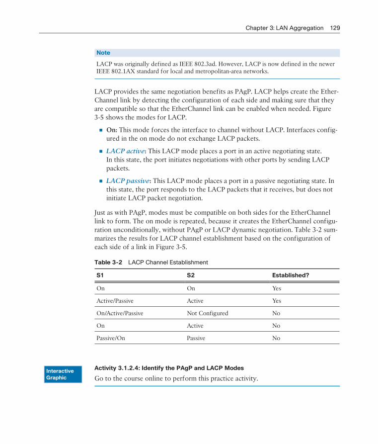
Chapter 3: LAN Aggregation 129
Note
LACP was originally defined as IEEE 802.3ad. However, LACP is now defined in the newer IEEE 802.1AX standard for local and metropolitan-area networks.
LACP provides the same negotiation benefits as PAgP. LACP helps create the Ether-Channel link by detecting the configuration of each side and making sure that they are compatible so that the EtherChannel link can be enabled when needed. Figure 3-5 shows the modes for LACP.
On: This mode forces the interface to channel without LACP. Interfaces config-ured in the on mode do not exchange LACP packets.
LACP active: This LACP mode places a port in an active negotiating state. In this state, the port initiates negotiations with other ports by sending LACP packets.
LACP passive: This LACP mode places a port in a passive negotiating state. In this state, the port responds to the LACP packets that it receives, but does not initiate LACP packet negotiation.
Just as with PAgP, modes must be compatible on both sides for the EtherChannel link to form. The on mode is repeated, because it creates the EtherChannel configu-ration unconditionally, without PAgP or LACP dynamic negotiation. Table 3-2 sum-marizes the results for LACP channel establishment based on the configuration of each side of a link in Figure 3-5.
Table 3-2 LACP Channel Establishment
S1 S2 Established?
On On Yes
Active/Passive Active Yes
On/Active/Passive Not Configured No
On Active No
Passive/On Passive No
Activity 3.1.2.4: Identify the PAgP and LACP Modes
Go to the course online to perform this practice activity.InteractiveGraphic
130 Scaling Networks Companion Guide
Link Aggregation Configuration (3.2)This section discusses EtherChannel configuration, verification, and troubleshooting.
Configuring EtherChannel (3.2.1)
Configuring EtherChannel is simple enough as long as the network administrator is aware of the limitations.
Configuration Guidelines (3.2.1.1)
The following guidelines and restrictions are useful for configuring EtherChannel:
EtherChannel support: All Ethernet interfaces on all modules must support EtherChannel with no requirement that interfaces be physically contiguous, or on the same module.
Speed and duplex: Configure all interfaces in an EtherChannel to operate at the same speed and in the same duplex mode, as shown in Figure 3-6.
VLAN match: All interfaces in the EtherChannel bundle must be assigned to the same VLAN, or be configured as a trunk (also shown in Figure 3-6).
Range of VLANs: An EtherChannel supports the same allowed range of VLANs on all the interfaces in a trunking EtherChannel. If the allowed range of VLANs is not the same, the interfaces do not form an EtherChannel, even when set to auto or desirable mode.
Figure 3-6 shows example topologies. In the top topology, a channel is established because none of the restrictions apply. In the bottom topology, the duplex mode doesn’t match, so a channel is not established.
If these settings must be changed, configure them in port channel interface configu-ration mode. After the port channel interface is configured, any configuration that is applied to the port channel interface also affects individual interfaces. However, configurations that are applied to the individual interfaces do not affect the port channel interface. Therefore, making configuration changes to an interface that is part of an EtherChannel link can cause interface compatibility issues.
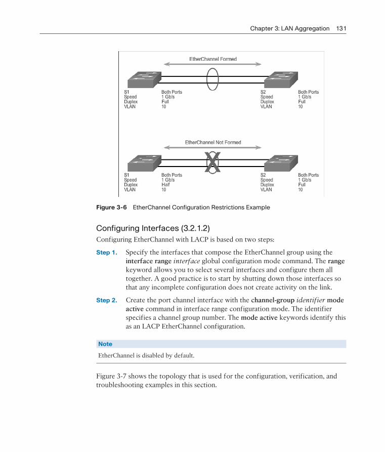
Chapter 3: LAN Aggregation 131
Figure 3-6 EtherChannel Configuration Restrictions Example
Configuring Interfaces (3.2.1.2)
Configuring EtherChannel with LACP is based on two steps:
Step 1. Specify the interfaces that compose the EtherChannel group using the interface range interface global configuration mode command. The range keyword allows you to select several interfaces and configure them all together. A good practice is to start by shutting down those interfaces so that any incomplete configuration does not create activity on the link.
Step 2. Create the port channel interface with the channel-group identifier mode active command in interface range configuration mode. The identifier specifies a channel group number. The mode active keywords identify this as an LACP EtherChannel configuration.
Note
EtherChannel is disabled by default.
Figure 3-7 shows the topology that is used for the configuration, verification, and troubleshooting examples in this section.

132 Scaling Networks Companion Guide
Figure 3-7 EtherChannel Configuration Topology
In Example 3-1, the FastEthernet0/1 and FastEthernet0/2 interfaces are bundled into EtherChannel interface port channel 1. To change Layer 2 settings on the port channel interface, enter port channel interface configuration mode using the inter-face port-channel command, followed by the interface identifier. In the example, the EtherChannel is configured as a trunk interface with allowed VLANs specified. Interface port channel 1 is configured as a trunk with allowed VLANs 1, 2, and 20.
Example 3-1 Configuring EtherChannel with LACP
S1(config)# interface range FastEthernet0/1 - 2
S1(config-if-range)# channel-group 1 mode active
S1(config-if-range)# interface port-channel 1
S1(config-if)# switchport mode trunk
S1(config-if)# switchport trunk allowed vlan 1,2,20
Packet Tracer Activity 3.2.1.3: Configuring EtherChannel
Three switches have just been installed. There are redundant uplinks between the switches. Usually, only one of these links could be used; otherwise, a bridging loop might occur. However, using only one link utilizes only half of the available band-width. EtherChannel allows up to eight redundant links to be bundled together into one logical link. In this lab, you will configure Port Aggregation Protocol (PAgP), a Cisco EtherChannel protocol, and Link Aggregation Control Protocol (LACP), an IEEE 802.3ad open standard version of EtherChannel.
Lab 3.2.1.4: Configuring EtherChannel
In this lab, you will complete the following objectives:
Part 1: Configure Basic Switch Settings
Part 2: Configure PAgP
Part 3: Configure LACP
Packet Tracer Activity

Chapter 3: LAN Aggregation 133
Verifying and Troubleshooting EtherChannel (3.2.2)
This topic discusses several useful commands available for verifying and trouble-shooting EtherChannel.
Verifying EtherChannel (3.2.2.1)
There are a number of commands to verify an EtherChannel configuration. First, the show interface port-channel command displays the general status of the port chan-nel interface. In Example 3-2, the Port Channel 1 interface is up.
Example 3-2 show interface port-channel Command
S1# show interface Port-channel1
Port-channel1 is up, line protocol is up (connected)
Hardware is EtherChannel, address is 0cd9.96e8.8a01 (bia 0cd9.96e8.8a01)
MTU 1500 bytes, BW 200000 Kbit/sec, DLY 100 usec,
reliability 255/255, txload 1/255, rxload 1/255
Encapsulation ARPA, loopback not set
<output omitted>
When several port channel interfaces are configured on the same device, use the show etherchannel summary command to simply display one line of information per port channel. In Example 3-3, the switch has one EtherChannel configured; group 1 uses LACP.
Example 3-3 show etherchannel summary Command
S1# show etherchannel summary
Flags: D - down P - bundled in port-channel
I - stand-alone s - suspended
H - Hot-standby (LACP only)
R - Layer3 S - Layer2
U - in use f - failed to allocate aggregator
M - not in use, minimum links not met
u - unsuitable for bundling
w - waiting to be aggregated
d - default port
Number of channel-groups in use: 1
Number of aggregators: 1

134 Scaling Networks Companion Guide
Group Port-channel Protocol Ports
------+-------------+-----------+-----------------------------------------------
1 Po1(SU) LACP Fa0/1(P) Fa0/2(P)
The interface bundle consists of the FastEthernet0/1 and FastEthernet0/2 interfaces. Group 1 is a Layer 2 EtherChannel and is in use, as indicated by the letters SU next to the port channel number.
Use the show etherchannel port-channel command to display information about a specific port channel interface, as shown in Example 3-4.
Example 3-4 show etherchannel port-channel Command
S1# show etherchannel Port-channel
Channel-group listing:
----------------------
Group: 1
----------
Port-channels in the group:
---------------------------
Port-channel: Po1 (Primary Aggregator)
------------
Age of the Port-channel = 0d:00h:25m:17s
Logical slot/port = 2/1 Number of ports = 2
HotStandBy port = null
Port state = Port-channel Ag-Inuse
Protocol = LACP
Port security = Disabled
Ports in the Port-channel:
Index Load Port EC state No of bits
------+------+------+------------------+-----------
0 00 Fa0/1 Active 0
0 00 Fa0/2 Active 0
Time since last port bundled: 0d:00h:05m:41s Fa0/2
Time since last port Un-bundled: 0d:00h:05m:48s Fa0/2
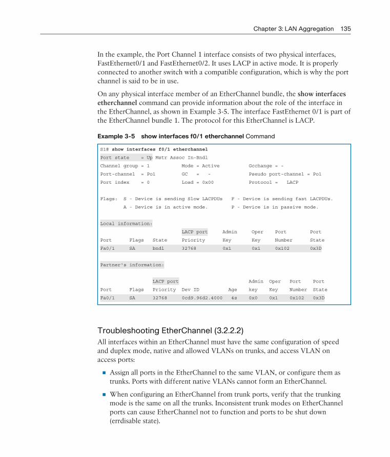
Chapter 3: LAN Aggregation 135
In the example, the Port Channel 1 interface consists of two physical interfaces, FastEthernet0/1 and FastEthernet0/2. It uses LACP in active mode. It is properly connected to another switch with a compatible configuration, which is why the port channel is said to be in use.
On any physical interface member of an EtherChannel bundle, the show interfaces etherchannel command can provide information about the role of the interface in the EtherChannel, as shown in Example 3-5. The interface FastEthernet 0/1 is part of the EtherChannel bundle 1. The protocol for this EtherChannel is LACP.
Example 3-5 show interfaces f0/1 etherchannel Command
S1# show interfaces f0/1 etherchannel
Port state = Up Mstr Assoc In-Bndl
Channel group = 1 Mode = Active Gcchange = -
Port-channel = Po1 GC = - Pseudo port-channel = Po1
Port index = 0 Load = 0x00 Protocol = LACP
Flags: S - Device is sending Slow LACPDUs F - Device is sending fast LACPDUs.
A - Device is in active mode. P - Device is in passive mode.
Local information:
LACP port Admin Oper Port Port
Port Flags State Priority Key Key Number State
Fa0/1 SA bndl 32768 0x1 0x1 0x102 0x3D
Partner's information:
LACP port Admin Oper Port Port
Port Flags Priority Dev ID Age key Key Number State
Fa0/1 SA 32768 0cd9.96d2.4000 4s 0x0 0x1 0x102 0x3D
Troubleshooting EtherChannel (3.2.2.2)
All interfaces within an EtherChannel must have the same configuration of speed and duplex mode, native and allowed VLANs on trunks, and access VLAN on access ports:
Assign all ports in the EtherChannel to the same VLAN, or configure them as trunks. Ports with different native VLANs cannot form an EtherChannel.
When configuring an EtherChannel from trunk ports, verify that the trunking mode is the same on all the trunks. Inconsistent trunk modes on Ether Channel ports can cause EtherChannel not to function and ports to be shut down ( errdisable state).
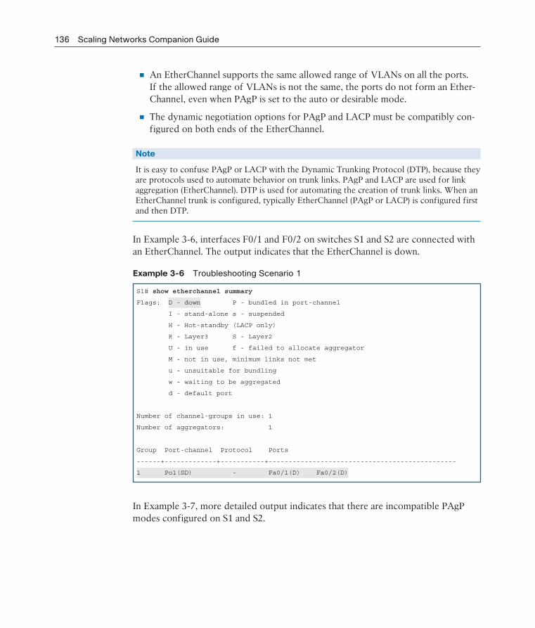
136 Scaling Networks Companion Guide
An EtherChannel supports the same allowed range of VLANs on all the ports. If the allowed range of VLANs is not the same, the ports do not form an Ether-Channel, even when PAgP is set to the auto or desirable mode.
The dynamic negotiation options for PAgP and LACP must be compatibly con-figured on both ends of the EtherChannel.
Note
It is easy to confuse PAgP or LACP with the Dynamic Trunking Protocol (DTP), because they are protocols used to automate behavior on trunk links. PAgP and LACP are used for link aggregation (EtherChannel). DTP is used for automating the creation of trunk links. When an EtherChannel trunk is configured, typically EtherChannel (PAgP or LACP) is configured first and then DTP.
In Example 3-6, interfaces F0/1 and F0/2 on switches S1 and S2 are connected with an EtherChannel. The output indicates that the EtherChannel is down.
Example 3-6 Troubleshooting Scenario 1
S1# show etherchannel summary
Flags: D - down P - bundled in port-channel
I - stand-alone s - suspended
H - Hot-standby (LACP only)
R - Layer3 S - Layer2
U - in use f - failed to allocate aggregator
M - not in use, minimum links not met
u - unsuitable for bundling
w - waiting to be aggregated
d - default port
Number of channel-groups in use: 1
Number of aggregators: 1
Group Port-channel Protocol Ports
------+-------------+-----------+-----------------------------------------------
1 Po1(SD) - Fa0/1(D) Fa0/2(D)
In Example 3-7, more detailed output indicates that there are incompatible PAgP modes configured on S1 and S2.
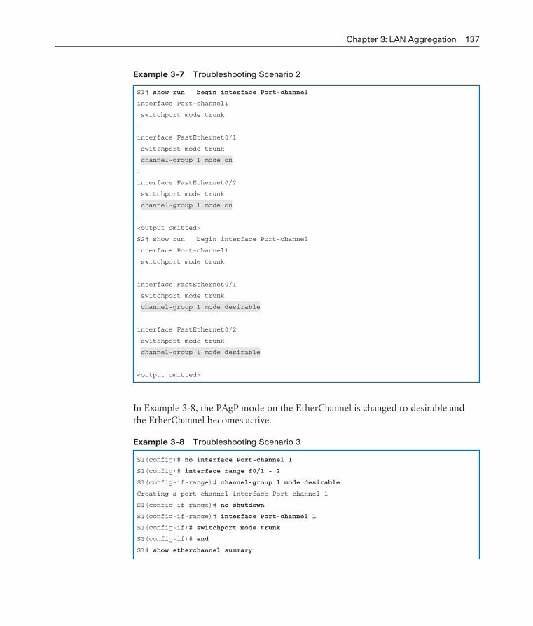
Chapter 3: LAN Aggregation 137
Example 3-7 Troubleshooting Scenario 2
S1# show run | begin interface Port-channel
interface Port-channel1
switchport mode trunk
!
interface FastEthernet0/1
switchport mode trunk
channel-group 1 mode on
!
interface FastEthernet0/2
switchport mode trunk
channel-group 1 mode on
!
<output omitted>
S2# show run | begin interface Port-channel
interface Port-channel1
switchport mode trunk
!
interface FastEthernet0/1
switchport mode trunk
channel-group 1 mode desirable
!
interface FastEthernet0/2
switchport mode trunk
channel-group 1 mode desirable
!
<output omitted>
In Example 3-8, the PAgP mode on the EtherChannel is changed to desirable and the EtherChannel becomes active.
Example 3-8 Troubleshooting Scenario 3
S1(config)# no interface Port-channel 1
S1(config)# interface range f0/1 - 2
S1(config-if-range)# channel-group 1 mode desirable
Creating a port-channel interface Port-channel 1
S1(config-if-range)# no shutdown
S1(config-if-range)# interface Port-channel 1
S1(config-if)# switchport mode trunk
S1(config-if)# end
S1# show etherchannel summary

138 Scaling Networks Companion Guide
Flags: D - down P - bundled in port-channel
I - stand-alone s - suspended
H - Hot-standby (LACP only)
R - Layer3 S - Layer2
U - in use f - failed to allocate aggregator
M - not in use, minimum links not met
u - unsuitable for bundling
w - waiting to be aggregated
d - default port
Number of channel-groups in use: 1
Number of aggregators: 1
Group Port-channel Protocol Ports
------+-------------+-----------+-----------------------------------------------
1 Po1(SU) PAgP Fa0/1(P) Fa0/2(P)
Note
EtherChannel and spanning tree must interoperate. For this reason, the order in which EtherChannel-related commands are entered is important, which is why (in Example 3-8) you see interface Port-Channel 1 removed and then re-added with the channel-group command, as opposed to directly changed. If one tries to change the configuration directly, spanning tree errors cause the associated ports to go into the blocking or errdisabled state.
Packet Tracer Activity 3.2.2.3: Troubleshooting EtherChannel
Four switches were recently configured by a junior technician. Users are complain-ing that the network is running slowly and would like you to investigate.
Lab 3.2.2.4: Troubleshooting EtherChannel
In this lab, you will complete the following objectives:
Part 1: Build the Network and Load Device Configurations
Part 2: Troubleshoot EtherChannel
Packet Tracer Activity
Chapter 3: LAN Aggregation 139
Summary (3.3)
Class Activity 3.3.1.1: Linking Up
Many bottlenecks occur on your small- to medium-sized business network, even though you have configured VLANs, STP, and other network traffic options on the company’s switches.
Instead of keeping the switches as they are currently configured, you would like to try EtherChannel as an option for, at least, part of the network to see whether it will decrease traffic congestion between your access and distribution layer switches.
Your company uses Catalyst 3560 switches at the distribution layer and Catalyst 2960 and 2950 switches at the access layer of the network. To verify whether these switches can perform EtherChannel, you visit the site “The System Requirements to Implement EtherChannel on Catalyst Switches.” This site allows you to gather more information to determine whether EtherChannel is a good option for the equipment and network currently in place.
After researching the models, you decide to use a simulation software program to practice configuring EtherChannel before implementing it live on your network. As a part of this procedure, you ensure that the equipment simulated in Packet Tracer will support these practice configurations.
Packet Tracer Activity 3.3.1.2: Skills Integration Challenge
In this activity, two routers are configured to communicate with each other. You are responsible for configuring subinterfaces to communicate with the switches. You will configure VLANs, trunking, and EtherChannel with PVST. The Internet devices are all preconfigured.
EtherChannel aggregates multiple switched links together to load-balance over redundant paths between two devices. All ports in one EtherChannel must have the same speed, duplex setting, and VLAN information on all interfaces on the devices at both ends. Settings configured in the port channel interface configuration mode will also be applied to the individual interfaces in that EtherChannel. Settings config-ured on individual interfaces will not be applied to the EtherChannel or to the other interfaces in the EtherChannel.
PAgP is a Cisco-proprietary protocol that aids in the automatic creation of Ether-Channel links. PAgP modes are on, PAgP desirable, and PAgP auto. LACP is part of an IEEE specification that also allows multiple physical ports to be bundled into one logical channel. The LACP modes are on, LACP active, and LACP passive. PAgP
Packet Tracer Activity
140 Scaling Networks Companion Guide
and LACP do not interoperate. The on mode is repeated in both PAgP and LACP because it creates an EtherChannel unconditionally, without the use of PAgP or LACP. The default for EtherChannel is that no mode is configured.
PracticeThe following activities provide practice with the topics introduced in this chapter. The Labs and Class Activities are available in the companion Scaling Networks Lab
Manual (ISBN 978-1-58713-325-1). The Packet Tracer Activities PKA files are found in the online course.
Class Activities
Class Activity 3.0.1.2: Imagine This
Class Activity 3.3.1.1: Linking Up
Labs
Lab 3.2.1.4: Configuring EtherChannel
Lab 3.2.2.4: Troubleshooting EtherChannel
Packet Tracer Activities
Packet Tracer Activity 3.2.1.3: Configuring EtherChannel
Packet Tracer Activity 3.2.2.3: Troubleshooting EtherChannel
Packet Tracer Activity 3.3.1.2: Skills Integration Challenge
Packet Tracer Activity

Chapter 3: LAN Aggregation 141
Check Your Understanding QuestionsComplete all the review questions listed here to test your understanding of the topics and concepts in this chapter. The appendix “Answers to ‘Check Your Understanding’ Questions” lists the answers.
1. Which statement is true about EtherChannel technology?
A. EtherChannel relies on existing switch ports.
B. STP does not run on EtherChannel links.
C. Configuration tasks must be done on individual ports.
D. Links must be upgraded to support EtherChannel.
2. What are advantages of using EtherChannel technology? (Choose three.)
A. EtherChannel uses multiple logical links to provide redundancy.
B. Load balancing is not needed with EtherChannel.
C. The Spanning Tree Protocol shuts down the unused interfaces in the bundle to avoid loops.
D. A spanning tree recalculation is not required when a single link within the channel goes down.
E. There is no need to upgrade links to faster connections to increase bandwidth.
F. Configuration tasks can be done on the EtherChannel interface.
3. Refer to Figure 3-8. An administrator tried to implement an EtherChannel between two switches by grouping the six physical ports as shown. However, the administrator was not successful. What is the reason for that?
Fa0/0
Fa0/1
Gi0/0Fa0/0
Fa0/1
Gi0/0
Figure 3-8 Question 3 Exhibit
A. An EtherChannel link can only be implemented on Fast Ethernet interfaces.
B. An EtherChannel link can only be implemented on Gigabit Ethernet interfaces.
C. An EtherChannel link can only be formed by grouping interfaces of the same type.
D. An EtherChannel link can only be created between Layer 3 switches.

142 Scaling Networks Companion Guide
4. Refer to Figure 3-9. An administrator wants to form an EtherChannel between the two switches by using the Port Aggregation Protocol. If switch S1 is config-ured to be in auto mode, which mode should be configured on S2 to form the EtherChannel?
Fa0/0
Fa0/1
Fa0/0
Fa0/1S1 S2
Figure 3-9 Question 4 Exhibit
A. On
B. Auto
C. Desirable
D. Off
5. When a range of ports is being configured for EtherChannel, which mode will configure PAgP so that it initiates the EtherChannel negotiation?
A. Active
B. Auto
C. Desirable
D. Passive
6. Which of the following protocols are used to implement EtherChannel? (Choose two.)
A. Spanning Tree Protocol
B. Rapid Spanning Tree Protocol
C. Port Aggregation Protocol
D. Link Aggregation Control Protocol
E. Cisco Discovery Protocol
7. What will happen if a network administrator puts a port that is part of an Ether-Channel bundle into a different VLAN than the other ports in that bundle?
A. The EtherChannel bundle will stay up only if PAgP is used.
B. The EtherChannel bundle will stay up only if LACP is used.
C. The EtherChannel bundle will stay up if either PAgP or LACP is used.
D. The EtherChannel bundle will stay up if the ports were configured with no negotiation between the switches to form the EtherChannel.
E. The EtherChannel will fail.
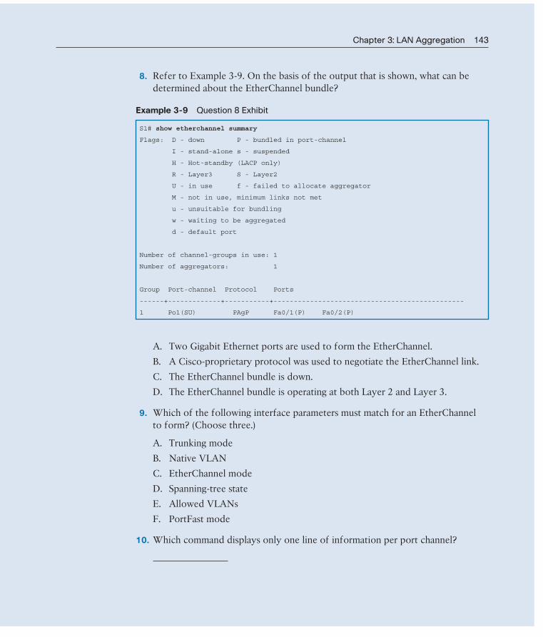
Chapter 3: LAN Aggregation 143
8. Refer to Example 3-9. On the basis of the output that is shown, what can be determined about the EtherChannel bundle?
Example 3-9 Question 8 Exhibit
S1# show etherchannel summary
Flags: D - down P - bundled in port-channel
I - stand-alone s - suspended
H - Hot-standby (LACP only)
R - Layer3 S - Layer2
U - in use f - failed to allocate aggregator
M - not in use, minimum links not met
u - unsuitable for bundling
w - waiting to be aggregated
d - default port
Number of channel-groups in use: 1
Number of aggregators: 1
Group Port-channel Protocol Ports
------+-------------+-----------+-----------------------------------------------
1 Po1(SU) PAgP Fa0/1(P) Fa0/2(P)
A. Two Gigabit Ethernet ports are used to form the EtherChannel.
B. A Cisco-proprietary protocol was used to negotiate the EtherChannel link.
C. The EtherChannel bundle is down.
D. The EtherChannel bundle is operating at both Layer 2 and Layer 3.
9. Which of the following interface parameters must match for an EtherChannel to form? (Choose three.)
A. Trunking mode
B. Native VLAN
C. EtherChannel mode
D. Spanning-tree state
E. Allowed VLANs
F. PortFast mode
10. Which command displays only one line of information per port channel?

This page intentionally left blank
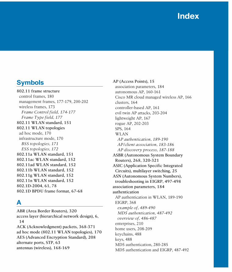
Index
Symbols802.11 frame structure
control frames, 180management frames, 177-179, 200-202wireless frames, 173
Frame Control field, 174-177
Frame Type field, 177
802.11 WLAN standard, 151802.11 WLAN topologies
ad hoc mode, 170infrastructure mode, 170
BSS topologies, 171
ESS topologies, 172
802.11a WLAN standard, 151802.11ac WLAN standard, 152802.11ad WLAN standard, 152802.11b WLAN standard, 152802.11g WLAN standard, 152802.11n WLAN standard, 152802.1D-2004, 61, 78802.1D BPDU frame format, 67-68
AABR (Area Border Routers), 320access layer (hierarchical network design), 6,
14ACK (Acknowledgment) packets, 368-371ad hoc mode (802.11 WLAN topologies), 170AES (Advanced Encryption Standard), 208alternate ports, STP, 63antennas (wireless), 168-169
AP (Access Points), 15association parameters, 184autonomous AP, 160-161Cisco MR cloud managed wireless AP, 166clusters, 164controller-based AP, 161evil twin AP attacks, 203-204lightweight AP, 167rogue AP, 202-203SPS, 164WLAN
AP authentication, 189-190
AP/client association, 183-186
AP discovery process, 187-188
ASBR (Autonomous System Boundary Routers), 268, 320-321
ASIC (Application Specific Integrated Circuits), multilayer switching, 25
ASN (Autonomous System Numbers), troubleshooting in EIGRP, 497-498
association parameters, 184authentication
AP authentication in WLAN, 189-190EIGRP, 368
example of, 489-490
MD5 authentication, 487-492
overview of, 486-487
enterprises, 210home users, 208-209keychains, 488keys, 488MD5 authentication, 280-285MD5 authentication and EIGRP, 487-492
584 authentication
BID (Bridge ID), 61bridge priority, 74extended system ID, 62, 74-76PVST+ configuration, 91-92
blocking port state, PVST+, 82blocking state, 60-61Bluetooth, 149boot system command, upgrading IOS images
via, 534-535bounded updates (EIGRP), 365, 371BPDU (Bridge Protocol Data Unit) frames,
59-62802.1D BPDU frame format, 67-68process of, 69-72RSTP, 86
BPDU Guard, PVST+, 93-95branch routers, 28bridge priority (BID), 74broadband, 150broadcast multiaccess networks, 251broadcast storms, Layer 2 loops, 54-56BSA (Basic Service Areas), BSS topologies, 172BSS (Basic Service Set) topologies, 171-172BSSID (Basic Service Set Identifiers), BSS
topologies, 172business wireless solutions, 159buying IOS licenses, 539
Ccampus LAN switches, 18Catalyst 2960 switches, PVST+ configuration,
90caveats, 521CEF (Cisco Express Forwarding), 484cellular broadband, 150channel management (WLAN)
frequency channel saturationDSSS, 191
FHSS, 192
OFDM, 192-193
selecting channels, 193-196
null authentication, 280open authentication, 189open system authentication, 206password authentication, 280RADIUS servers, 210routing, 280-285shared key authentication, 189
RADIUS servers, 210
WEP, 206
WPA, 206-209
WPA2, 207-209
autonomous AP (Access Points), 160-161autonomous system numbers, IPv4 EIGRP
configuration, 379-381
Bbackbone area (OSPF), 316, 319backbone routers, 320backup ports, STP, 63backups
IOScreating, 531-533
IOS licenses, 545-546
TFTP servers, 531
WLAN configurations, 224bandwidth
EIGRPbandwidth metrics, 406-408
IPv4 bandwidth utilization, 479-480
IPv6 bandwidth utilization, 480
increasing, 13, 169BDR (Backup Designated Routers), 255
election process, 261-263OSPF interface prioritization, 265-267verifying
adjacencies, 259-261
roles, 256-258
BGP (Border Gateway Protocol), autonomous system numbers, 380

convergence 585
multiarea OSPFmultiarea OSPFv2, 330-332
multiarea OSPFv3, 332-334
PVST+BID, 91-92
BPDU Guard, 93-95
Catalyst 2960 default configuration, 90
load-balancing, 95-97
PortFast, 93-95
RSTP, 98-100single-area OSPF, 242-243single-area OSPFv3, 247-248Smart Wi-Fi interface, 218-219STP
expected topologies versus actual topologies,
102
failures, consequences of, 103-105
failures, repairing, 105
spanning tree status overview, 102
STP topology analysis, 101
wireless clients, 225wireless routers, 211-212WLAN
backups, 224
clients, 225
Linksys EA6500 routers, 213-216
Linksys Smart Wi-Fi Home page, 217
Smart Wi-Fi interface, 218-219
wireless routers, 211-212
connectivitywireless connectivity, 14WLAN connectivity, troubleshooting, 227-229
control frames, 180controller-based AP (Access Points), 161convergence
DUALFS, 424-428
FSM, 423
EIGRPDUAL and FS, 424-428
DUAL and FSM, 423
route discovery, 401
channel settings, AP/client associations, 184Cisco Enterprise Architecture, 7
Enterprise Campus, 8Enterprise Edge, 9Service Provider Edge, 9
Cisco Feature Navigator, 523Cisco IOS. See IOSCisco License Registration Portal, obtaining
licenses from, 540Cisco Meraki cloud architecture, 165-166Cisco Unified wireless network architecture,
167CLI commands
routers, 31-32switches, 39-40
CLM (Cisco License Manager), obtaining licenses from, 539
cloudCisco Meraki cloud architecture, 165-166cloud-managed switches, 18
clusters, 11, 164collision avoidance, 181commands
CLI commandsrouters, 31-32
switches, 39-40
show commandsrouters, 34-39
switches, 40-43
composite metrics and EIGRP, 402-404configuring
bandwidth metrics (EIGRP), 407EIGRP
authentication, 488-490
automatic summarization, 459-460
IPv4 configuration, 377-381, 429-431
IPv6 configuration, 429-443
manual summarization, 471
interarea route summarization, 340-342Linksys EA6500 routers, 213-216Linksys Smart Wi-Fi Home page, 217MD5 authentication, 282

586 copying IOS images
DSSS (Direct Sequence Spread Spectrum), 191DTP (Dynamic Trunking Protocol), 136DUAL, 364, 413
convergenceFS, 424-428
FSM, 423
FC, 415FS, 415-417
DUAL convergence, 424-428
topology tables, 420-422
FSM, 414convergence, 423
debugging, 425-427
RD, 415successors and FD, 414-415topology tables, 417-422
dynamic routing, 240-242
Eedge ports, RSTP, 87-88EHF (Extremely High Frequency), 151EIGRP (Enhanced Interior Gateway Routing
Protocol), 17, 363-364, 454ACK packets, 368-371ASN, troubleshooting, 497-498authentication, 368
example of, 489-490
MD5 authentication, 487-492
overview of, 486-487
bandwidthIPv4 bandwidth utilization, 479-480
IPv6 bandwidth utilization, 480
bounded updates, 365, 371default route propagation, 474-478DUAL, 364, 413
convergence, 423-428
FC, 415
FS, 415-417, 420-428
FSM, 414
RD, 415
copying IOS images, 533-534core layer (hierarchical network design), 6, 239CSMA/CA (Carrier Sense Multiple Access with
Collision Avoidance), 181CST (Common Spanning Tree), 78CTS floods, 200
DDashboard (web-based), Cisco Meraki cloud,
166data center switches, 18Data technology packages, 537DCF (Distributed Coordination Function), 181Dead intervals, 273-278debugging FSM, 425-427default gateways
limitations of, 106virtual routers, 107
default port costs, STP, 64delay metrics and EIGRP, 408-409designated ports, STP, 63device lists (Smart Wi-Fi tools), 220device modules as clusters, 11directional Wi-Fi antennas, 168disabled ports
PVST+, 82STP, 63
disconnect attacks (spoofed), 200distance vector routing protocols, EIGRP, 17distribution layer (hierarchical network design),
6, 239DoS (Denial of Service) attacks, 199-202Down state (OSPF), 287DR (Designated Routers), 255
election process, 261-263OSPF interface prioritization, 265-267verifying
adjacencies, 259-261
roles, 256-258
DROTHER, 255, 260-263

EIGRP (Enhanced Interior Gateway Routing Protocol) 587
bandwidth utilization, 480
default route propagation, 477-478
Hello intervals, 482
Hold timers, 482
IPv4 EIGRP configuration comparisons,
430-431
ipv6 eigrp interface command, 437-439
IPv6 routing process, 436-437
link-local addresses, 432-435
load-balancing, 484-486
manual summarization, 472-474
network topologies, 432-434
passive interfaces, 439
troubleshooting, 495-504
verifying, 440-443
load-balancing, 365IPv4 configuration, 482-486
IPv6 configuration, 484-486
messagesencapsulating, 373
packet headers, 374-375
TLV fields, 373-376
metricsbandwidth metrics, 406-408
calculating a metric, 409-413
composite metrics, 402-404
delay metrics, 408-409
interface values, 405
neighbor adjacencies, 364, 386, 399network statements, troubleshooting, 502-504NSF, 498Null0 interface
automatic summarization, 464-465
routing loops, 466-467
summary routes, 466-467
partial updates, 365, 371passive interface, operating as a, 500-502PDM, 365-366Query packets, 368-369, 372Reply packets, 368-369, 373
successors and FD, 414-415
topology tables, 417-422
equal cost load-balancing, 365fine-tuning interfaces
bandwidth utilization, 479-480
Hello intervals, 480-482
Hold timers, 480-482
load-balancing, 482-486
Hello intervalsIPv4 configuration, 480-481
IPv6 configuration, 482
Hello packets, 367-370, 399Hold timers
IPv4 configuration, 480-481
IPv6 configuration, 482
hybrid routing protocol, EIGRP as, 365interfaces, troubleshooting, 498-500IPv4 configuration, 429
authentication, 488-492
automatic summarization, 455-467, 504-507
autonomous system numbers, 379-381
bandwidth utilization, 479-480
default route propagation, 474-477
EIGRP router ID, 382-385
Hello intervals, 480-481
Hold timers, 480-481
IPv6 EIGRP configuration comparisons,
430-431
load-balancing, 482-486
loopback addresses as EIGRP router ID,
384-385
manual summarization, 468-472
network command, 385-389
network topology, 377-379
passive interfaces, 389-392
router EIGRP command, 381-382
troubleshooting, 493-507
verifying, 392-398
wildcard masks, 387-389
IPv6 configuration, 429authentication, 490-492

588 EIGRP (Enhanced Interior Gateway Routing Protocol)
fixed configuration routers, 29
functions, 27
in-band management, 31
IOS files, 30
IOS licenses, 30
managing, 30
modular routers, 29
network edge routers, 28
out-of-band management, 31
requirements, 26
service provider routers, 29
show commands, 34-39
scalability, 4designing for, 11
switches, 21
switchescampus LAN switches, 18
CLI commands, 39-40
cloud-managed switches, 18
cost of, 21
data center switches, 18
fixed configuration switches, 19
forwarding rates, 22
frame buffers, 21
height of, 20
in-band management, 31
IOS files, 30
IOS licenses, 30
managing, 30
modular configuration switches, 20
multilayer switching, 25-26
out-of-band management, 31
PoE, 23
port density, 21-22
port speed, 21
power, 21
rack unit considerations, 20
reliability, 21
scalability, 21
service provider switches, 18
show commands, 40-43
route discoveryconvergence, 401
neighbor adjacency, 399
topology tables, 400-401
router ID, IPv4 EIGRP configuration, 382-385routing tables, troubleshooting, 500-507RTP, 365-367security, 368, 486-492summarization
automatic summarization, 455-467, 504-507
manual summarization, 468-474
topology tables, 400-401, 417-422troubleshooting
ASN, 497-498
automatic summarization, 504-507
commands, 493-495
connectivity issues, 495-496
interfaces, 498-500
neighbor issues, 496-497
network statements, 502-504
routing tables, 500-507
unequal cost load-balancing, 365update packets, 368, 371, 401
EM (Extended Maintenance) releases, IOS Software Release 15.0, 524-525
encapsulating EIGRP messages, 373encryption, 208Enterprise Campus, 8Enterprise Edge, 9enterprise networks
access layer, 14bandwidth, 13defining, 4EtherChannel, 14link aggregation, 13OSPF, 15redundancy, planning for, 12reliability, 5routers
branch routers, 28
CLI commands, 31-32
Frame Type field (wireless frames) 589
FD (Feasible Distance), 414-415Feature Navigator (Cisco), 523FHRP (First Hop Redundancy protocols), 51
default gateways, limitations of, 106GLBP, 110
syntax checker, 114
verifying, 112-113
HSRP, 109syntax checker, 114
verifying, 110-111
IRDP, 110route redundancy, 107router failover, 108virtual routers, 107VRRPv2, 110VRRPv3, 110
FHSS (Frequency Hopping Spread Spectrum), 192
filenames (IOS), 528-530firmware (WLAN), updating, 230-231fixed configuration routers, 29fixed configuration switches, 19fixes. See caveatsforwarding port state, PVST+, 82forwarding rates, switches, 22frame buffers, switches, 21Frame Control field (wireless frames), 174-177frames
802.11 frame structurecontrol frames, 180
management frames, 177-179, 200-202
wireless frames, 173-177
BPDU frames, 59-62802.1D BPDU frame format, 67-68
process of, 69-72
RSTP, 86
Ethernet frames, TTL attribute, 54multiple frame transmission, Layer 2 loops, 54unicast frames, OSI layer redundancy, 57
Frame Type field (wireless frames), 177
stackable configuration switches, 20
wire speed, 22
virtual networking, 18equal cost load-balancing and EIGRP, 365
IPv4 configuration, 482-484IPv6 configuration, 484
ESA (Extended Service Areas), ESS topologies, 173
ESS (Extended Service Set topologies), 172EtherChannel
advantages of, 124configuring
guidelines, 130
interfaces, 131-132
implementation restrictions, 125-126LACP, 128-132link aggregation, 14load-balancing, 124network scalability, 11PAgP, 126-128redundancy, 125STP, 124switch ports, 124troubleshooting, 135-138verifying, 133-135
EthernetEthernet frames, TTL attribute, 54Ethernet ports, wire speed, 22PoE switches, 23
Evaluation licenses (IOS), 544-545evil twin AP attacks, 203-204Exchange state (OSPF), 288ExStart state (OSPF), 288Extended System ID, 62, 74-76, 83external route summarization, 337
Ffailover capability, 5failover domains, 9-10FC (Feasibility Condition), 415

590 FS (Feasible Successors)
Hold timers (EIGRP)IPv4 configuration, 480-481IPv6 configuration, 482
hotspots (personal), tethering, 171HSRP (Hot Standby Router Protocol), 109
syntax checker, 114verifying, 110-111
hybrid routing protocol, EIGRP as, 365
IIANA (Internet Assigned Numbers Authority),
autonomous system numbers, 379IEEE (Institute of Electrical and Electronics
Engineers)802.11 WLAN standard, 151802.11a WLAN standard, 151802.11b WLAN standard, 152802.11ac WLAN standard, 152802.11ad WLAN standard, 152802.11g WLAN standard, 152802.11n WLAN standard, 152802.1D-2004, 61, 78Wi-Fi certification, 153
images (IOS)backups, 531-533copying, 533-534naming conventions, 519
filenames, 528-530
IOS Software Release 12.4, 519-522
IOS Software Release 15.0, 523-526
software release families, 519
software trains, 519-525
system image packaging, 522, 526
upgrading via boot system command, 534-535in-band management, 31infrastructure mode (802.11 WLAN
topologies), 170BSS topologies, 171ESS topologies, 172
Init state (OSPF), 287
FS (Feasible Successors), 415-417DUAL convergence, 424-428topology tables, 420-422
FSM (Finite State Machine)debugging, 425-427DUAL and, 414, 423
Full state (OSPF), 288
G-Hgateways (default)
limitations of, 106virtual routers, 107
GLBP (Gateway Load-balancing Protocol), 110syntax checker, 114verifying, 112-113
guest access (Smart Wi-Fi tools), 221
headers (packet), EIGRP messages, 374-375heavy AP (Access Points). See autonomous APHello intervals, 273-278, 480-482Hello packets, 367-370, 399hierarchical network design
access layer, 6core layer, 6distribution layer, 6failover domains, 9-10multilayer switches, 10redundancy, 52-57routers
access layer, 14
bandwidth, 13
deploying, 10
EtherChannel, 14
link aggregation, 13
OSPF, 15
redundancy, 12
scalability, 11
switch blocks, 10switches, 10
IPv6 (Internet Protocol version 6) 591
IOS Software Release 12.4mainline train, 519-522system image packaging, 522T train, 520-522
IOS Software Release 15.0EM releases, 524-525mainline train, 523-525system image packaging, 526T releases, 524-526T train, 523-525
IP Base technology packages, 536IPv4 (Internet Protocol version 4)
EIGRP configuration, 429authentication, 488-492
automatic summarization, 455-467, 504-507
autonomous system numbers, 379-381
bandwidth utilization, 479-480
default route propagation, 474-477
EIGRP router ID, 382-385
Hello intervals, 480-481
Hold timers, 480-481
IPv6 EIGRP configuration comparisons,
430-431
load-balancing, 482-486
loopback addresses as EIGRP router ID,
384-385
manual summarization, 468-472
network command, 385-389
network topology, 377-379
passive interfaces, 389-392
router EIGRP command, 381-382
troubleshooting, 493-507
verifying, 392-398
wildcard masks, 387-389
IPv6 (Internet Protocol version 6)EIGRP configuration, 429
authentication, 490-492
bandwidth utilization, 480
default route propagation, 477-478
Hello intervals, 482
Hold timers, 482
installing IOS licenses, 541, 546-547interarea route summarization, 336-342interference, WLAN security threats, 199internal routers, 320IOS (Internetwork Operating System), 518
caveats, 521images
copying, 533-534
creating backups, 531-533
filenames, 528-530
naming conventions, 519-530
software release families, 519
software trains, 519-525
system image packaging, 522, 526
TFTP servers as backups, 531
upgrading via boot system command,
534-535
licensing, 536backups, 545-546
Cisco License Registration Portal, 540
CLM, 539
Evaluation licenses, 544-545
installing licenses, 541
managing, 30
obtaining licenses, 539-541
overview of, 536
permanent licenses, 541-542
process of, 538
purchasing licenses, 539
RTU licenses, 544-545
technology packages, 536-538
UDI, 540
uninstalling licenses, 546-547
verifying licenses, 542-544
memory requirements, 530PAK, 527, 539-540software release families, 519software trains
IOS Software Release 12.4, 519-522
IOS Software Release 15.0, 523-525
system file management, 30, 519

592 IPv6 (Internet Protocol version 6)
licensing (IOS)backups, 545-546Cisco License Registration Portal, 540CLM, 539Evaluation licenses, 544-545installing licenses, 541managing, 30obtaining licenses, 539-541overview of, 536permanent licenses, 541-542process of, 538purchasing licenses, 539RTU licenses, 544-545technology packages, 536-538UDI, 540uninstalling licenses, 546-547verifying licenses, 542-544
lightweight AP (Access Points), Cisco Unified wireless network architecture, 167
link aggregation, 13defining, 122-123EtherChannel
advantages of, 124
configuration guidelines, 130
implementation restrictions, 125-126
interface configuration, 131-132
LACP, 128-132
PAgP, 126-128
troubleshooting, 135-138
verifying, 133-135
link-local addresses, IPv6 EIGRP configuration, 432-435
link-state routing protocolsEIGRP, 17OSPF, 15-16
Linksys EA6500 routers, configuring, 213-216Linksys Smart Wi-Fi Home page, configuring,
217listening port state, PVST+, 82load-balancing
CEF, 484
IPv4 EIGRP configuration comparisons,
430-431
ipv6 eigrp interface command, 437-439
IPv6 routing process, 436-437
link-local addresses, 432-435
load-balancing, 484-486
manual summarization, 472-474
network topologies, 432-434
passive interfaces, 439
troubleshooting, 495-504
verifying, 440-443
propagated routes, verifying via single-area OSPFv3, 272
IRDP (ICMP Router Discovery Protocol), 110ITU-R (International Telecommunication Union:
Radiocommunication Sector)radio frequencies and wireless technologies,
150Wi-Fi certification, 153
J-K-Lkeychains (authentication), 488keys
authentication, 488PAK, 527, 539-540
LACP (Link Aggregation Control Protocol), 128-132
LAN (Local Area Networks). See also WLANcampus LAN switches, 18redundancy, 12WLAN comparisons to, 154-156
large wireless deployment solutionsCisco Meraki cloud architecture, 165-166Cisco Unified wireless network architecture,
167Layer 2 loops
broadcast storms, 54-56MAC database instability, 53-55
learning port state, PVST+, 82
mulitaccess networks, OSPF 593
IOS files, 30IOS images
copying images, 533-534
creating backups, 531-533
TFTP servers as backups, 531
upgrading images via boot system
command, 534-535
IOS licenses, 30IOS system files, 519out-of-band management, 31
MCC (Meraki Cloud Controller), 166MD5 authentication
EIGRP and, 487-492routing, 280-285
media prioritization (Smart Wi-Fi tools), 222memory, IOS requirements, 530Meraki cloud architecture, 165-166messages (EIGRP)
encapsulating, 373packet headers, 374-375TLV fields, 373-376
metrics (EIGRP)bandwidth metrics, 406-408calculating a metric, 409-413composite metrics, 402-404delay metrics, 408-409interface values, 405
MIMO (Multiple-Input, Multiple-Output), increasing bandwidth via, 169
MITM (Man-In-The-Middle) attacks, 203-204modular configuration switches, 20modular routers, 29MST (Multiple Spanning Tree), characteristics
of, 79MSTP (Multiple Spanning Tree Protocol), 61,
78-79mulitaccess networks, OSPF
BDR, 255-267broadcast multiaccess networks, 251DR, 255-267DROTHER, 255, 260-263
EIGRP, 365IPv4 configuration, 482-486
IPv6 configuration, 484-486
equal cost load-balancing, 482-484EtherChannel, 124GLBP, 110
syntax checker, 114
verifying, 112-113
PVST+, 95-97unequal cost load-balancing, 485-486
Loading state (OSPF), 288loopback addresses as router ID, 384-385loops
blocking state, 60-61Layer 2 loops
broadcast storms, 54-56
MAC database instability, 53-55
routing loops, 465LSA (Link-State Advertisements)
LSA floods, multi-access networks, 253-255OSPF LSA Type 1, 322-323OSPF LSA Type 2, 323-324OSPF LSA Type 3, 324OSPF LSA Type 4, 325OSPF LSA Type 5, 326OSPF LSA types, 321-322
LSDB (Link-State Databases), verifying multiarea OSPF LSDB, 346-349
MMAC addresses, filtering, 205MAC databases, Layer 2 loops, 53-55mainline train
IOS Software Release 12.4, 519-522IOS Software Release 15.0, 523-525
maintenance, IOS Software Release 15.0, 524-526
management frames, 177-179, 200-202managing
in-band management, 31

594 mulitaccess networks, OSPF
Nnaming IOS images
filenames, 528-530IOS Software Release 12.4
mainline train, 519-522
system image packaging, 522
T train, 520-522
IOS Software Release 15.0mainline train, 523-525
system image packaging, 526
T train, 523-525
software release families, 519software trains, 519
IOS Software Release 12.4, 519-522
IOS Software Release 15.0, 523-526
NBMA (Nonbroadcast Multiaccess) networks, 252
network command, IPv4 EIGRP router configuration, 385-389
network edge routers, 28Network mode, AP/client associations, 184network statements, troubleshooting in EIGRP,
502-504network topologies, IPv6 EIGRP configuration,
432-434networks
access layer, 14bandwidth, increasing, 13broadcast multiaccess networks, 251Cisco Enterprise Architecture, 7
Enterprise Campus, 8
Enterprise Edge, 9
Service Provider Edge, 9
default gateways, limitations of, 106enterprise networks
access layer, 14
bandwidth, 13
defining, 4
EtherChannel, 14
link aggregation, 13
interface prioritization, 265-267LSA floods, 253-255NBMA networks, 252point-to-multipoint networks, 252point-to-point networks, 251virtual link networks, 253
multiarea OSPF (Open Shortest Path First), 16, 317ABR, 320advantages of, 318ASBR, 320-321backbone routers, 320configuring
multiarea OSPFv2, 330-332
multiarea OSPFv3, 332-334
implementing, 329-330internal routers, 320LSA Type 1, 322-323LSA Type 2, 323-324LSA Type 3, 324LSA Type 4, 325LSA Type 5, 326LSA types, 321-322route calculation, 328-329route redistribution, 321route summarization, 334-335
calculating summary routes, 339
external route summarization, 337
interarea route summarization, 336-342
routing table entries, 327single-area OSPF versus, 316two-layer area hierarchy, 319-320verifying, 342
general settings, 343-345
LSDB, 346-349
OSPFv3, 349-352
routes, 345-346
multilayer switching, 10, 25-26multiple frame transmission, Layer 2 loops, 54

networks 595
MSTP, 61
planning for, 12
RSTP, 61
STP, 52-67, 78-79
reliability, 5remote networks
routing, 239-240
switches, 239
routersbranch routers, 28
CLI commands, 31-32
deploying, 10
fixed configuration routers, 29
functions, 27
in-band management, 31
IOS files, 30
IOS licenses, 30
managing, 30
modular routers, 29
network edge routers, 28
out-of-band management, 31
requirements, 26
service provider routers, 29
show commands, 34-39
scalability, 4designing for, 11
routing versus switching, 238
switches, 21
switch blocks, deploying, 10switches
campus LAN switches, 18
CLI commands, 39-40
cloud-managed switches, 18
cost of, 21
data center switches, 18
fixed configuration switches, 19
forwarding rates, 22
frame buffers, 21
height of, 20
in-band management, 31
IOS files, 30
OSPF, 15
redundancy, 12
reliability, 5
scalability, 4, 11
EtherChannel, 14failover domains, 9-10hierarchical network design
access layer, 6, 14
bandwidth, 13
core layer, 6
distribution layer, 6
EtherChannel, 14
failover domains, 9-10
link aggregation, 13
multilayer switches, 10
OSPF, 15
redundancy, 12, 52-57
routers, 10
scalability, 11
switch blocks, 10
link aggregation, 13multiaccess networks and OSPF
BDR, 255-267
broadcast multiaccess networks, 251
DR, 255-267
DROTHER, 255, 260-263
interface prioritization, 265-267
LSA floods, 253-255
NBMA networks, 252
point-to-multipoint networks, 252
point-to-point networks, 251
virtual link networks, 253
multilayer switches, deploying, 10NBMA networks, 252OSPF, 15point-to-multipoint networks, 252point-to-point networks, 251redundancy
blocking state, 60-61
FHRP, 51, 106-114
hierarchical network design, 52-57

596 networks
BDR, 255election process, 261-263
interface prioritization, 265-267
verifying adjacencies, 259-261
verifying roles, 256-258
broadcast multiaccess networks, 251Dead intervals, 273-278defining, 238Down state, 287DR, 255
election process, 261-263
interface prioritization, 265-267
verifying adjacencies, 259-261
verifying roles, 256-258
DROTHER, 255, 260-263Exchange state, 288ExStart state, 288features of, 241-242fine-tuning interfaces, 273-278Full state, 288Hello intervals, 273-278Init state, 287interface prioritization, 265-267internal routers, 320Loading state, 288LSA Type 1, 322-323LSA Type 2, 323-324LSA Type 3, 324LSA Type 4, 325LSA Type 5, 326LSA types, 321-322multiaccess networks
broadcast multiaccess networks, 251
LSA floods, 253-255
NBMA networks, 252
point-to-multipoint networks, 252
point-to-point networks, 251
virtual link networks, 253
multiarea OSPF, 16, 317ABR, 320
advantages of, 318
IOS licenses, 30
managing, 30
modular configuration switches, 20
multilayer switching, 10, 25-26
out-of-band management, 31
PoE, 23
port density, 21-22
port speed, 21
power, 21
rack unit considerations, 20
reliability, 21
scalability, 21
service provider switches, 18
show commands, 40-43
stackable configuration switches, 20
wire speed, 22
virtual link networks, 253virtual networking, 18
NIC (Network Interface Cards), wireless NIC, 156-157
NSF (Nonstop-Forwarding), 498null authentication, routing, 280Null0 interface and EIGRP
automatic summarization, 464-465
routing loops, 466-467
summary routes, 466-467
OOFDM (Orthogonal Frequency Division
Multiplexing), 192-193omnidirectional Wi-Fi antennas, 168open authentication, AP authentication in
WLAN, 189open system authentication, 206OSPF (Open Shortest Path First), 15
ABR, 320ASBR, 268, 320-321backbone area, 316, 319backbone routers, 320
Point-to-Point links, RSTP 597
single-area OSPFv3configuring, 247-248
Dead intervals, 273-274, 277-278
fine-tuning interfaces, 273-274, 277-278
Hello intervals, 273-274, 277-278
propagating default static routes, 271-272
security, 279-285
states of OSPF, 287-288
troubleshooting, 286-304
verifying, 249-250
verifying propagated routes, 272
troubleshooting, 286commands list, 288-291
components of, 292
single-area OSPFv2, 293-299
single-area OSPFv3, 299-304
states of OSPF, 287-288
Two-Way state, 287virtual link networks, 253
out-of-band management, 31
Ppackaging IOS
IOS Software Release 12.4, 522IOS Software Release 15.0, 526
packet headers, EIGRP messages, 374-375PAgP (Port Aggregation Protocol), 126-128PAK (Product Activation Keys), 527, 539-540parental controls (Smart Wi-Fi tools), 221partial updates (EIGRP), 365, 371passive interface, EIGRP as a, 500-502passwords
AP/client association, 184authentication, routing, 280
PDM (Protocol-Dependent Modules) and EIGRP, 17, 365-366
permanent IOS licenses, 541-542personal hotspots, tethering, 171PoE (Power over Ethernet), switches, 23point-to-multipoint networks, 252Point-to-Point links, RSTP, 89
ASBR, 320-321
backbone routers, 320
configuring multiarea OSPFv2, 330-332
configuring multiarea OSPFv3, 332-334
implementing, 329-330
internal routers, 320
LSA Type 1, 322-323
LSA Type 2, 323-324
LSA Type 3, 324
LSA Type 4, 325
LSA Type 5, 326
LSA types, 321-322
route calculation, 328-329
route redistribution, 321
route summarization, 334-342
routing table entries, 327
single-area OSPF versus, 316
two-layer area hierarchy, 319-320
verifying, 342
verifying general settings, 343-345
verifying LSDB, 346-349
verifying OSPFv3, 349-352
verifying routes, 345-346
NBMA networks, 252point-to-multipoint networks, 252point-to-point networks, 251security
authentication, 280-285
routing, 279-281
single-area OSPF, 16configuring, 242-243
multiarea OSPF versus, 316
verifying, 244-247
single-area OSPFv2Dead intervals, 273-276
fine-tuning interfaces, 273-276
Hello intervals, 273-276
propagating default static routes, 268-269
security, 279-285
states of OSPF, 287-288
troubleshooting, 286-299
verifying propagated routes, 269-271

598 point-to-point networks
Q-Rquad zero static default routes, EIGRP default
route propagation, 474-478Query packets, 368-369, 372
radio frequencies and wireless technologies, 150-151
RADIUS servers, authentication, 210Rapid PVST+. See RSTPRD (Reported Distance), 415rebuilds. See caveatsredundancy
blocking state, 60-61Enterprise Campus, 8EtherChannel, 125FHRP, 51
default gateways, limitations of, 106
GLBP, 110-114
HSRP, 109-114
IRDP, 110
route redundancy, 107
router failover, 108
virtual routers, 107
VRRPv2, 110
VRRPv3, 110
hierarchical network design, 52-57LAN, 12planning for, 12route redundancy, 107STP, 12
802.1D-2004, 78
alternate ports, 63
backup ports, 63
BID, 74-76
BPDU frames, 59-62, 67-72
characteristics of, 79
configuration issues, 101-105
CST, 78
default port costs, 64
designated ports, 63
point-to-point networks, 251port density
Enterprise Campus, 8switches, 21-22
PortFast, PVST+, 93-95ports
alternate ports, STP, 63backup ports, STP, 63blocking state, 60-61default port costs, STP, 64designated ports, STP, 63disabled ports, STP, 63edge ports, RSTP, 87-88Ethernet ports, wire speed, 22PVST+ port states, 82-83root ports, STP, 62speed, switches, 21switch ports, EtherChannel, 124UDP ports, RADIUS Authentication/
Accounting, 210power, switches, 21prioritizing media (Smart Wi-Fi tools), 222propagating
default static routes in EIGRP, 474-478static routes
single-area OSPFv2, 268-269
single-area OSPFv3, 271-272
purchasing IOS licenses, 539PVST+ (Per VLAN Spanning Tree Plus), 78
characteristics of, 79configuring
BID, 91-92
BPDU Guard, 93-95
Catalyst 2960 default configuration, 90
load-balancing, 95-97
PortFast, 93-95
Extended System ID, 83overview of, 80-81port states, 82-83

routing 599
OSPF interface prioritization, 265-267
verifying adjacencies, 259-261
verifying roles, 256-258
branch routers, 28CLI commands, 31-32core layer, 239deploying, 10discovery, EIGRP
convergence, 401
neighbor adjacency, 399
topology tables, 400-401
distribution layer, 239DR, 255
election process, 261-263
OSPF interface prioritization, 265-267
verifying adjacencies, 259-261
verifying roles, 256-258
DROTHER, 255, 260-263dynamic routing, 240-242EIGRP, 17
authentication, 486-492
default route propagation and quad zero
static default routes, 474-478
IPv6 EIGRP routing process, 436-437
route discovery, 399-401
router ID, 382-385
routing tables, 442-443, 464-465, 500-507
static route propagation, 474-478
summarization, 455-474, 504-507
summary routes, 466-474
verifying IPv6 EIGRP configuration,
442-443
external route summarization, 337failover and FHRP, 108fixed configuration routers, 29functions, 27interarea route summarization, 336-342internal routers, 320IOS memory requirements, 530IPv6 EIGRP routing process, 436-437Linksys EA6500 routers, configuring, 213-216
disabled ports, 63
IEEE 802.1D-2004, 61
MST, 79
MSTP, 61, 78-79
operation of, 59-60
OSI layer redundancy, 52-57
path cost, 64-67
port roles, 61-63
PVST+, 78-83, 90-97
root bridges, 63-64
root ports, 62
RSTP, 61, 78-79, 84-89, 98-100
STA, 61-67
redundant paths, 12reliability
enterprise networks, 5switches, 21
remote networksrouting
discovering networks, 239
dynamic routing, 240
switches, discovering networks, 239Reply packets, 368-369, 373RF (Radio Frequency), WLAN, 155RIR (Regional Internet Registry), autonomous
system numbers, 380rogue AP (Access Points), 202-203root bridges
BID, PVST+ configuration, 91-92designating, 61STP, 63-64
root ports, STP, 62router EIGRP command, IPv4 EIGRP
configuration, 381-382routing, 29
ABR, 320ASBR, 268, 320-321authentication, 280-285, 486-492backbone routers, 320BDR, 255
election process, 261-263

600 routing
Dead intervals, 273-278
DR, 255-267
DROTHER, 255, 260-263
features of, 241-242
fine-tuning interfaces, 273-278
Hello intervals, 273-278
interface prioritization, 265-267
internal routers, 320
LSA Type 1, 322-323
LSA Type 2, 323-324
LSA Type 3, 324
LSA Type 4, 325
LSA Type 5, 326
LSA types, 321-322
multiaccess networks, 251-255
NBMA networks, 252
point-to-multipoint networks, 252
point-to-point networks, 251
security, 279-285
states of, 287-288
troubleshooting, 286-304
virtual link networks, 253
quad zero static default routes and EIGRP default route propagation, 474-478
redistributing, 320-321redundancy, 107remote networks
discovering, 239
dynamic routing, 240
routing loops, example of, 465routing tables, EIGRP, 442-443, 464-465,
500-507security, 279-285service provider routers, 2show commands, 34-39single-area OSPF, 16
configuring, 242-243
multiarea OSPF versus, 316
verifying, 244-247
single-area OSPFv2Dead intervals, 273-276
fine-tuning interfaces, 273-276
loopback addresses as router ID, 384-385managing
in-band management, 31
IOS files, 30
IOS licenses, 30
out-of-band management, 31
modular routers, 29multiarea OSPF, 16, 317
ABR, 320
advantages of, 318
ASBR, 320-321
backbone routers, 320
configuring multiarea OSPFv2, 330-332
configuring multiarea OSPFv3, 332-334
implementing, 329-330
internal routers, 320
LSA Type 1, 322-323
LSA Type 2, 323-324
LSA Type 3, 324
LSA Type 4, 325
LSA Type 5, 326
LSA types, 321-322
route calculation, 328-329
route redistribution, 321
route summarization, 334-342
routing table entries, 327
single-area OSPF versus, 316
two-layer area hierarchy, 319-320
verifying, 342
verifying general settings, 343-345
verifying LSDB, 346-349
verifying OSPFv3, 349-352
verifying routes, 345-346
network edge routers, 28networking requirements, 26OSPF, 15
ABR, 320
ASBR, 320-321
backbone area, 316, 319
backbone routers, 320
BDR, 255-267
broadcast multiaccess networks, 251
security 601
Ssatellite broadband, 150scalability
designing for, 11enterprise networks, 4routing versus switching, 238switches, 21
SEC (Security) technology packages, 537security
authentication, 280-285keychains, 488
keys, 488
MD5 authentication, 487-492
EIGRP, 368, 486-492OSPF, 279-285wireless technologies, 198
CTS floods, 200
DoS attacks, 199-202
encryption, 208
enterprise authentication, 210
evil twin AP attacks, 203-204
home user authentication, 208-209
interference, 199
MAC address filtering, 205
MITM attacks, 203-204
open system authentication, 206
rogue AP, 202-203
shared key authentication, 206-207
spoofed disconnect attacks, 200
SSID cloaking, 205
WLAN, 198CTS floods, 200
DoS attacks, 199-202
encryption, 208
enterprise authentication, 210
evil twin AP attacks, 203-204
home user authentication, 208-209
interference, 199
MAC address filtering, 205
MITM attacks, 203-204
Hello intervals, 273-276
propagating default static routes, 268-269
security, 279-285
troubleshooting, 286-299
verifying propagated routes, 269-271
single-area OSPFv3configuring, 247-248
Dead intervals, 273-274, 277-278
fine-tuning interfaces, 273-274, 277-278
Hello intervals, 273-274, 277-278
propagating default static routes, 271-272
security, 279-285
troubleshooting, 286-304
verifying, 249-250
verifying propagated routes, 272
static routing, 239-240propagating in EIGRP, 474-478
propagating routes in OSPFv2, 268-269
propagating routes in OSPFv3, 271-272
verifying propagated routes in OSPFv2,
269-271
verifying propagated routes in OSPFv3, 272
successors and FD, 414-415summarization
EIGRP, 455-474, 504-507
multiarea OSPF, 334-342
switching versus, 238updates, 280-281virtual routers, 107, 110wireless home routers, 157-158wireless routers, 15, 211-212
RSTP (Rapid Spanning Tree Protocol), 61, 78BPDU frames, 86characteristics of, 79configuring, 98-100edge ports, 87-88link types, 88-89overview of, 84-86
RTP (Real-time Transfer Protocol), 365-367RTU (Right-To-Use) licenses, 544-545

602 security
troubleshooting, 286commands list, 288-291
components of, 292
neighbor issues, 293-297
routing tables, 297-299
states of OSPF, 287-288
single-area OSPFv3configuring, 247-248Dead intervals, 273-274, 277-278default static routes, propagating, 271-272fine-tuning interfaces, 273-278Hello intervals, 273-274, 277-278security
authentication, 280-285
routing, 279-281
troubleshooting, 286, 299-304commands list, 288-291
components of, 292
states of OSPF, 287-288
verifying, 249-250small wireless deployment solutions, 162-164Smart Wi-Fi interface, configuring, 218-219Smart Wi-Fi tools, 220-223software licensing (IOS)
backups, 545-546Cisco License Registration Portal, 540CLM, 539Evaluation licenses, 544-545installing licenses, 541obtaining licenses, 539-541overview of, 536permanent licenses, 541-542process of, 538purchasing licenses, 539RTU licenses, 544-545technology packages, 536-538UDI, 540uninstalling licenses, 546-547verifying licenses, 542-544
software release families, 519
open system authentication, 206
rogue AP, 202-203
shared key authentication, 206-207
spoofed disconnect attacks, 200
SSID cloaking, 205
Security mode, AP/client associations, 184Server Farm and Data Center Module, 8servers
RADIUS servers, authentication, 210TFTP servers as IOS image backups, 531
Service Provider Edge, 9service provider routers, 29service provider switches, 18Services Module, 8shared key authentication
AP authentication in WLAN, 189RADIUS servers, 210WEP, 206WPA, 206, 209WPA2, 207-209
shared links, RSTP, 89SHF (Super High Frequency), 151show commands
routers, 34-39switches, 40-43
Single-Area OSPF (Open Shortest Path First), 16configuring, 242-243multiarea OSPF versus, 316verifying, 244-247
single-area OSPFv2Dead intervals, 273-276default static routes
propagating, 268-269
verifying propagated routes, 269-271
fine-tuning interfaces, 273-276Hello intervals, 273-276security
authentication, 280-285
routing, 279-281
summarization 603
MAC database instability, 53-55
unicast frames, 57
PVST+, 78BID, 91-92
BPDU Guard, 93-95
Catalyst 2960 default configuration, 90
characteristics of, 79
Extended System ID, 83
load-balancing, 95-97
overview of, 80-81
PortFast, 93-95
port states, 82-83
Rapid PVST+, 78-79redundancy, 12RSTP, 61, 78
BPDU frames, 86
characteristics of, 79
configuring, 98-100
edge ports, 87-88
link types, 88-89
overview of, 84-86
STAalternate ports, 63
backup ports, 63
default port costs, 64
designated ports, 63
disabled ports, 63
path cost, 64-67
port roles, 61-63
root bridges, 63-64
root ports, 62
successors and FD, 414-415summarization
EIGRPautomatic summarization, 455-467, 504-507
manual summarization, 468-474
multiarea OSPF, 334-335calculating summary routes, 339
external route summarization, 337
interarea route summarization, 336-342
software trainsIOS Software Release 12.4, 519-522IOS Software Release 15.0, 523-525
speed tests (Smart Wi-Fi tools), 223spoofed disconnect attacks, 200SPS (Single Point Setup) and AP, 164SSID (Service Set Identifiers)
SSID cloaking, 205wireless home routers, 158
stackable configuration switches, 20static routing, 239, 240
propagatingEIGRP, 474-478
single-area OSPFv2, 268-269
single-area OSPFv3, 271-272
verifying propagated routessingle-area OSPFv2, 269-271
single-area OSPFv3, 272
STP (Spanning Tree Protocol)802.1D-2004, 61, 78BID, 74-76BPDU frames, 59-62
802.1D BPDU frame format, 67-68
process of, 69-72
RSTP, 86
characteristics of, 79configuring
expected topologies versus actual topologies,
102
failures, consequences of, 103-105
failures, repairing, 105
spanning tree status overview, 102
STP topology analysis, 101
CSTdevelopment of, 61EtherChannel, 124MST, characteristics of, 79MSTP, 61, 78-79operation of, 59-60OSI layer redundancy, 52
broadcast storms, 54-56

604 summary routes and EIGRP
show commands, 40-43stackable configuration switches, 20wire speed, 22
system file management (IOS), 519
TT (standard maintenance) releases, IOS
Software Release 15.0, 524-526T (Technology) train
IOS Software Release 12.4, 520-522IOS Software Release 15.0, 523-525
technology packages, 536-538tethering, 171TFTP servers as IOS image backups, 531TKIP (Temporal Key Integrity Protocol), 208TLV (Type, Length, Value) field, EIGRP
messages, 373-376topologies
802.11 WLAN topologies, 170-172EIGRP network topologies, IPv4 configuration,
377-379topology tables
DUAL and, 417-422
EIGRP, 417-422, 462-463
trains (software), 519IOS Software Release 12.4, 519-522IOS Software Release 15.0, 523-525
troubleshootingEIGRP
ASN, 497-498
automatic summarization, 504-507
commands, 493-495
connectivity issues, 495-496
interfaces, 498-500
neighbor issues, 496-497
network statements, 502-504
routing tables, 500-507
EtherChannel, 135-138OSPF, 286
commands list, 288-291
components of, 292
summary routes and EIGRPmanual summary routes, 468-474Null0 interface, 466-467
switch blocks, deploying, 10switches. See also virtual networking
BID, 61-62campus LAN switches, 18Catalyst 2960 switches, PVST+ configuration,
90CLI commands, 39-40cloud-managed switches, 18cost of, 21data center switches, 18edge ports, RSTP, 87-88EtherChannel, 124fixed configuration switches, 19forwarding rates, 22frame buffers, 21height of, 20Layer 2 loops
broadcast storms, 54-56
MAC database instability, 53-55
managingin-band management, 31
IOS files, 30
IOS licenses, 30
out-of-band management, 31
modular configuration switches, 20multilayer switching, 10, 25-26PoE, 23port density, 21-22port speed, 21power, 21rack unit considerations, 20reliability, 21remote networks, discovering, 239root bridges
designating, 61
STP, 63-64
routing versus, 238scalability, 21service provider switches, 18

Wi-Fi 605
bandwidth metric configuration, 407-408
default route propagation, 476-478
EIGRP router ID, 385
interfaces, 499-500
IPv4 configuration, 392-398
IPv6 configuration, 440-443
manual summarization, 471-472
passive interfaces, 392, 500-502
EtherChannel, 133-135IOS licenses, 542-544MD5 authentication, 284-285multiarea OSPF, 342
general settings, 343-345
LSDB, 346-349
OSPFv3, 349-352
routes, 345-346
single-area OSPF, 244-247, 269-271single-area OSPFv3, 249-250, 272
virtual link networks, 253virtual networking, 18virtual routers, 107, 110VLAN (Virtual Local Area Networks),
EtherChannel configuration guidelines, 130VRRPv2 (Virtual Router Redundancy Protocol
version 2), 110VRRPv3 (Virtual Router Redundancy Protocol
version 3), 110
Wweb-based Dashboard, Cisco Meraki cloud,
166WEP (Wired Equivalent Privacy), 206Wi-Fi, 149
antennas, 168-169certification, 153Linksys Smart Wi-Fi Home page, configuring,
217Smart Wi-Fi interface, configuring, 218-219Smart Wi-Fi tools, 220-223WPA, 206, 209WPA2, 207-209
single-area OSPFv2, 293-299
single-area OSPFv3, 299-304
states of OSPF, 287-288
WLAN, 226connectivity issues, 227-229
firmware updates, 230-231
TTL (Time To Live) attribute, Ethernet frames, 54
Two-Way state (OSPF), 287
UUC (Unified Communications) technology
packages, 537UDI (Unique Device Identifiers), IOS licensing,
540UDP (User Datagram Protocol) ports, RADIUS
Authentication/Accounting, 210UHF (Ultra High Frequency), 151unequal cost load-balancing and EIGRP, 365,
485-486unicast frames, OSI layer redundancy, 57uninstalling IOS licenses, 546-547updates
EIGRPbounded updates, 365, 371
partial updates, 365, 371
routing, 280-281update packets, 368, 371, 401WLAN firmware, 230, 231
upgrading IOS images via boot system command, 534-535
USB storage (Smart Wi-Fi tools), 223USB wireless adapters, 157
Vverifying
EIGRPASN, 497-498
authentication, 491-492
automatic summarization, 460-465
606 Wi-Fi Alliance, Wi-Fi certification
Cisco Unified wireless network architecture,
167
mobility, support for, 148radio frequencies and, 150-151satellite broadband, 150security, 198
CTS floods, 200
DoS attacks, 199-202
encryption, 208
enterprise authentication, 210
evil twin AP attacks, 203-204
home user authentication, 208-209
interference, 199
MAC address filtering, 205
MITM attacks, 203-204
open system authentication, 206
rogue AP, 202-203
shared key authentication, 206-207
spoofed disconnect attacks, 200
SSID cloaking, 205
small wireless deployment solutions, 162-164SPS, 164SSID, 158tethering, 171Wi-Fi, 149WiMAX, 150wireless antennas, 168-169wireless clients, 159WLAN, 149WPAN, 149WWAN, 149
WLAN (Wireless Local Area Networks), 149802.11 frame structure
control frames, 180
management frames, 177-179, 200-202
wireless frames, 173-177
802.11 WLAN standard, 151802.11 WLAN topologies
ad hoc mode, 170
infrastructure mode, 170-172
802.11a WLAN standard, 151
Wi-Fi Alliance, Wi-Fi certification, 153wildcard masks, IPv4 EIGRP router
configuration, 387-389WiMAX (Worldwide Interoperability for
Microwave Access), 150wire speeds
Ethernet ports, 22switches, 22
wireless access points. See APwireless clients, 159wireless connectivity, 14wireless frames, 173
Frame Control field, 174-177Frame Type field, 177
wireless NIC, 156-157wireless routers, 15
configuring, 211-212home routers, SSID, 157-158
wireless technologies802.11 WLAN standard, 151802.11 WLAN topologies, 170-172802.11a WLAN standard, 151802.11ac WLAN standard, 152802.11ad WLAN standard, 152802.11b WLAN standard, 152802.11g WLAN standard, 152802.11n WLAN standard, 152AP
autonomous AP, 160-161
controller-based AP, 161
evil twin AP attacks, 203-204
rogue AP, 202-203
benefits of, 148-149Bluetooth, 149business wireless solutions, 159cellular broadband, 150certification, 153clients, configuring, 225encryption, 208large wireless deployment solutions
Cisco Meraki cloud architecture, 165-166

enterprise authentication, 210
evil twin AP attacks, 203-204
home user authentication, 208-209
interference, 199
MAC address filtering, 205
MITM attacks, 203-204
open system authentication, 206
rogue AP, 202-203
shared key authentication, 206-207
spoofed disconnect attacks, 200
SSID cloaking, 205
small wireless deployment solutions, 162-164Smart Wi-Fi tools, 220-223SPS, 164troubleshooting, 226
connectivity issues, 227-229
firmware updates, 230-231
USB wireless adapters, 157wireless antennas, 168-169wireless AP
autonomous AP, 160-161
controller-based AP, 161
wireless clients, 159wireless home routers, 157-158wireless NIC, 156-157
WPA (Wi-Fi Protected Access), 206, 209WPA2 (Wi-Fi Protected Access 2), 207-209WPAN (Wireless Personal Area Networks),
149WWAN (Wireless Wide Area Networks), 149
X-Y-ZYagi antennas, 168
Yagi antennas 607
802.11ac WLAN standard, 152802.11ad WLAN standard, 152802.11b WLAN standard, 152802.11g WLAN standard, 152802.11n WLAN standard, 152AP
authentication, 189-190
client association, 183-186
discovery process, 187-188
evil twin AP attacks, 203-204
rogue AP, 202-203
business wireless solutions, 159certification, 153channel management
frequency channel saturation, 191-193
selecting channels, 193-196
clusters, 164configuring
backups, 224
clients, 225
Linksys EA6500 routers, 213-216
Linksys Smart Wi-Fi Home page, 217
Smart Wi-Fi interface, 218-219
wireless routers, 211-212
deployments, planning, 196-197LAN comparisons to, 154-156large wireless deployment solutions
Cisco Meraki cloud architecture, 165-166
Cisco Unified wireless network architecture,
167
operation ofAP authentication, 189-190
AP/client association, 183-186
AP discovery process, 187-188
CSMA/CA, 181
planning deployments, 196-197RF, 155security, 198
CTS floods, 200
DoS attacks, 199-202
encryption, 208