international journal of mechanical engineering ...iaeme.com/masteradmin/uploadfolder/art of...
TRANSCRIPT
International Journal of Mechanical Engineering and Technology (IJMET), ISSN 0976 –
6340(Print), ISSN 0976 – 6359(Online) Volume 4, Issue 2, March - April (2013) © IAEME
196
ART OF FATIGUE ANALYSIS OF HELICAL COMPRESSION SPRING
USED IN TWO-WHEELER HORN
Gajanan S. Rao*, Prof. R. R. Deshmukh**
*Department of Mechanical Engineering,
M G M’s Jawaharlal Nehru Engineering College, N-6, Cidco, Aurangabad.
Dr.B.A.M. University, Aurangabad, Maharashtra, India
** Department of Mechanical Engineering,
M G M’s Jawaharlal Nehru Engineering College N-6, Cidco, Aurangabad.
Dr.B.A.M. University, Aurangabad, Maharashtra, India.
ABSTRACT
Two-wheeler has a provision for a sounding a horn to be used while commuting so as
to warn the passerby of the approaching vehicle as well as a signal for maintaining a safe
distance or to communicate for any other reasons for safety. The horn is crucial as it is
directly related to safety and the malfunction may evoke secondary claims and may affect the
good-will of the customer. In most malfunction problems of two wheeler horns is due to
fatigue failure of spring in warranty period so it is important to calculate the fatigue life and
reduce fatigue failure in its intended working period (i.e. before 3,00,000 cycles). A typical
helical compression spring configuration of two wheeler horn is chosen for study. Life
analysis determines fatigue life of spring by the safe stress and corresponding pay load of the
helical compression spring. This work describes fatigue analysis of the helical compression
spring is performed using NASTRAN solver and compared with analytical results. The pre
processing of the spring model is done by using HYPERMESH software. The present work
attempts to analyze the life using MSC fatigue software and also verified by
experimentation. Life of spring found to be infinity using software analysis as well as
experimentally. To extend life in place of present spring co-axial (series) spring is analyzed.
Also factors affecting fatigue life of this compression spring are stated.
Keywords: Fatigue analysis, Geometric modeling, Helical compression spring, Life analysis,
Two-wheeler horn.
INTERNATIONAL JOURNAL OF MECHANICAL ENGINEERING
AND TECHNOLOGY (IJMET)
ISSN 0976 – 6340 (Print)
ISSN 0976 – 6359 (Online)
Volume 4, Issue 2, March - April (2013), pp. 196-208 © IAEME: www.iaeme.com/ijmet.asp Journal Impact Factor (2013): 5.7731 (Calculated by GISI) www.jifactor.com
IJMET
© I A E M E
International Journal of Mechanical Engineering and Technology (IJMET), ISSN 0976 –
6340(Print), ISSN 0976 – 6359(Online) Volume 4, Issue 2, March - April (2013) © IAEME
197
I. INTRODUCTION
A spring is an elastic object used to store mechanical energy, whose function is to
compress when loaded and to recover its original shape when the load is removed. In other
words it is also termed as a resilient member. Springs are elastic bodies (generally made up of
metals) that can be twisted, pulled, or stretched by some force. A spring is a flexible element
used to exert a force or a torque and, at the same time, to store energy. The force can be a
linear push or pull, or it can be radial.
II. LITERATURE REVIEW
Robert Stone [1] this paper describes a working definition of fatigue and a brief
discussion of fatigue characteristics. A short history will be presented as to how fatigue test
data has been evaluated historically. (e.g., S-N curves, Weibull distribution, modified
Goodman diagrams, etc.) Reviews the proper methods by which spring manufacturers should
estimate the fatigue life of helical compression springs during the design phase. Modified
Goodman diagrams have been sufficiently characterized to facilitate direct calculation of
predicted life. By using Modified Goodman diagrams few calculations are presented along
with a comparison to the results of traditional graphical methods.
William H. Skewis [2] discussed spring reliability factors, as springs tend to be highly
stressed because they are designed to fit into small spaces with the least possible weight and
lowest material cost and required to deliver the required force over a long period of time. The
reliability of a spring is related to its material strength, design characteristics, and the
operating environment. Corrosion protection of the spring steel has a significant impact on
reliability and so material properties, the processes used in the manufacturing of the spring,
operating temperature and corrosive media must all be known before any estimate of spring
reliability can be made. Spring reliability is also directly related to the surface quality and the
distribution, type and size of sub-surface impurities in the spring material.
G Harinath Gowd and E Venugopal Goud [3] in this paper describe “static analysis of
leaf spring”, used in automobile suspension systems. The advantage of leaf spring over
helical spring is that the ends of the spring may be guided along a definite path as it deflects
to act as a structural member in addition to energy absorbing device. The main function of
leaf spring is not only to support vertical load but also to isolate road induced vibrations. It is
subjected to millions of load cycles leading to fatigue failure. Static analysis determines the
safe stress and corresponding pay load of the leaf spring and also to study the behavior of
structures under practical conditions. The present work attempts to analyze the safe load of
the leaf spring, which will indicate the speed at which a comfortable speed and safe drive is
possible. Finite element analysis has been carried out to determine the safe stresses and pay
loads.
Mr. V. K. Aher, and Mr. P. M. Sonawane [4] in this paper describe,“Static and
Fatigue Analysis Of Multi Leaf Spring Used In The Suspension System of LCV”, has done
the work regarding the leaf spring used in automobiles and one of the components of
suspension system. The purpose of this paper is to predict the fatigue life of semi-elliptical
steel leaf spring along with analytical stress and deflection calculations. This present work
describes static and fatigue analysis of a modified steel leaf spring of a light commercial
vehicle (LCV). The dimensions of a modified leaf spring of a LCV are taken and are verified
by design calculations. The non-linear static analysis of 2D model of the leaf spring is
International Journal of Mechanical Engineering and Technology (IJMET), ISSN 0976 –
6340(Print), ISSN 0976 – 6359(Online) Volume 4, Issue 2, March - April (2013) © IAEME
198
performed using NASTRAN solver and compared with analytical results. The pre processing
of the modified model is done by using HYPERMESH software. The stiffness of the
modified leaf spring is studied by plotting load versus deflection curve for working range
loads. The simulation results are compared with analytical results. The fatigue life of the leaf
spring is also predicted using MSC Fatigue software. Shigley’s [5] book of “Design of
Mechanical Elements”, include, spring chapter. In this chapter we will discuss the more
frequently used types of springs, their necessary parametric relationships, and their design.
III. METHODOLOGY
Spring design in fatigue applications generally based on following consideration:
• Available space and required loads and deflections
• Method of stressing
• Rate of load application
• Operation environment
• Minimum fatigue life at required reliability
For life analysis and life enhancement of helical compression spring used in two-wheeler
horn following steps are used as a methodology.
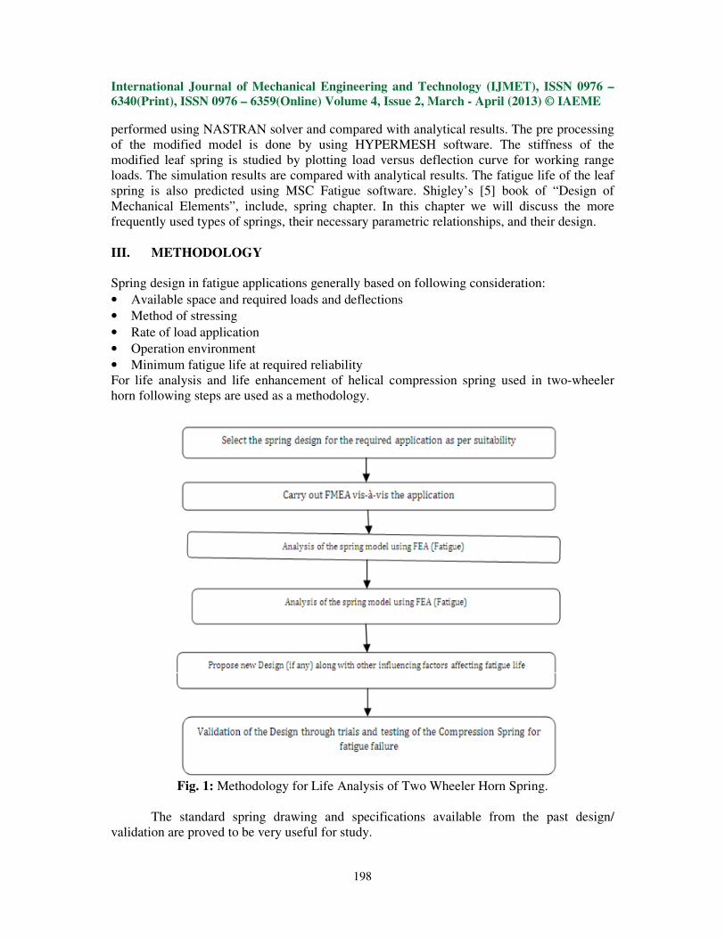
Fig. 1: Methodology for Life Analysis of Two Wheeler Horn Spring.
The standard spring drawing and specifications available from the past design/
validation are proved to be very useful for study.
International Journal of Mechanical Engineering and Technology (IJMET), ISSN 0976 –
6340(Print), ISSN 0976 – 6359(Online) Volume 4, Issue 2, March - April (2013) © IAEME
199
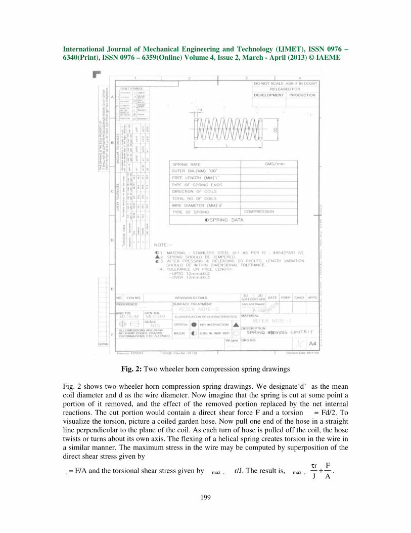
Fig. 2: Two wheeler horn compression spring drawings
Fig. 2 shows two wheeler horn compression spring drawings. We designate‘d’ as the mean
coil diameter and d as the wire diameter. Now imagine that the spring is cut at some point a
portion of it removed, and the effect of the removed portion replaced by the net internal
reactions. The cut portion would contain a direct shear force F and a torsion � = Fd/2. To
visualize the torsion, picture a coiled garden hose. Now pull one end of the hose in a straight
line perpendicular to the plane of the coil. As each turn of hose is pulled off the coil, the hose
twists or turns about its own axis. The flexing of a helical spring creates torsion in the wire in
a similar manner. The maximum stress in the wire may be computed by superposition of the
direct shear stress given by
�= F/A and the torsional shear stress given by �max�� r/J. The result is, �max� r F
J A
τ+ .
International Journal of Mechanical Engineering and Technology (IJMET), ISSN 0976 –
6340(Print), ISSN 0976 – 6359(Online) Volume 4, Issue 2, March - April (2013) © IAEME
200
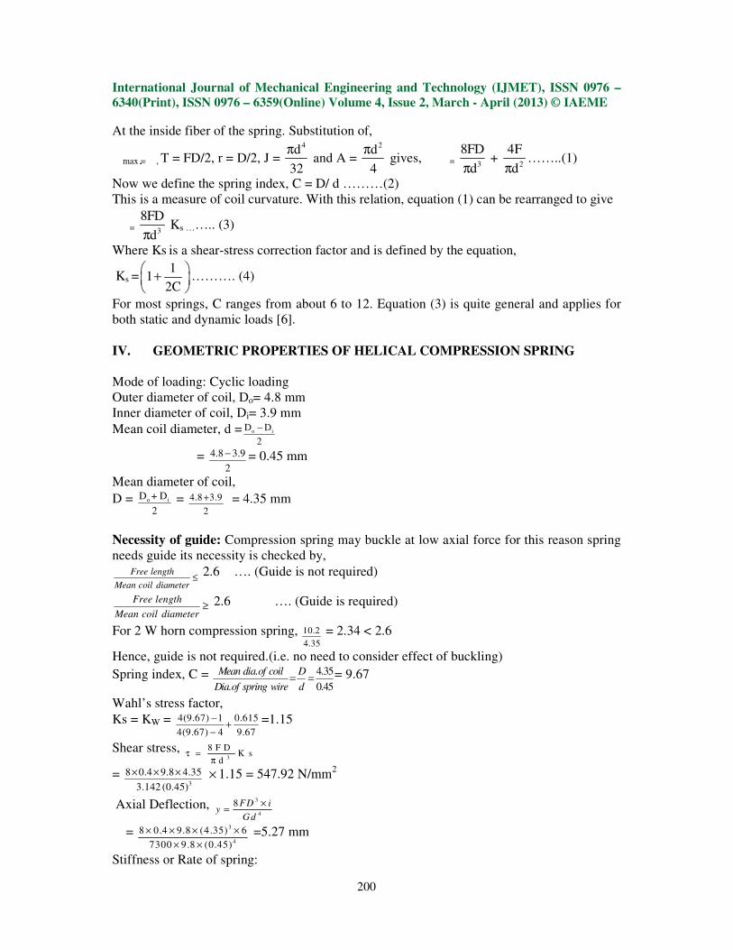
At the inside fiber of the spring. Substitution of,
�max =�, T = FD/2, r = D/2, J = 4d
32
π and A =
2d
4
π gives, � =
3
8FD
dπ +
2
4F
dπ……..(1)
Now we define the spring index, C = D/ d ………(2)
This is a measure of coil curvature. With this relation, equation (1) can be rearranged to give
� = 3
8FD
dπ Ks …….. (3)
Where Ks is a shear-stress correction factor and is defined by the equation,
Ks =1
12C
+
………. (4)
For most springs, C ranges from about 6 to 12. Equation (3) is quite general and applies for
both static and dynamic loads [6].
IV. GEOMETRIC PROPERTIES OF HELICAL COMPRESSION SPRING
Mode of loading: Cyclic loading
Outer diameter of coil, Do= 4.8 mm
Inner diameter of coil, Di= 3.9 mm
Mean coil diameter, d = o iD D
2
−
= 4.8 3.9
2
− = 0.45 mm
Mean diameter of coil,
D = o iD + D
2 = 4.8 +3.9
2
= 4.35 mm
Necessity of guide: Compression spring may buckle at low axial force for this reason spring
needs guide its necessity is checked by, Free length
Mean coil diameter≤
2.6 …. (Guide is not required)
Free length
Mean coil diameter≥ 2.6 …. (Guide is required)
For 2 W horn compression spring, 10.2
4.35
= 2.34 < 2.6
Hence, guide is not required.(i.e. no need to consider effect of buckling)
Spring index, C = . 4.35
. 0.45
Mean dia of coil D
Dia of spring wire d= = = 9.67
Wahl’s stress factor,
Ks = KW = 4(9.67) 1 0.615
4(9.67) 4 9.67
−+
−=1.15
Shear stress, 3
8 F DK s
dτ =
π
= 3
8 0.4 9.8 4.35
3.142 (0.45)
× × × × 1.15 = 547.92 N/mm2
Axial Deflection, 3
4
8 FD iy
Gd
×=
= 3
4
8 0.4 9.8 (4.35) 6
7300 9.8 (0.45)
× × × ×
× × =5.27 mm
Stiffness or Rate of spring:

International Journal of Mechanical Engineering and Technology (IJMET), ISSN 0976 –
6340(Print), ISSN 0976 – 6359(Online) Volume 4, Issue 2, March - April (2013) © IAEME
201
Fo = 0.4
5.27
F
y=
= 0.076 kg/mm
Free length, Io ≥ (I +n) d + y + a
Io ≥ (6 +1)0.45 + 5.16 + 0.25(5.16)
Io ≥ 9.6 mm
Actual free length is taken as 10.2 mm
Pitch, 2 10.2 2(0.45)
6
oI dp
i
− −= = = 1.55 mm
V. HELICAL COMPRESSION SPRING DESIGN FOR STATIC SERVICE
The preferred range of spring index is, 4 ≤ C ≤ 12 , with the lower indexes being more
difficult to form (because of the danger of surface cracking) and springs with higher indexes
tending to tangle often enough to require individual packing. This can be the first item of the
design assessment. The recommended range of active turns is 3≤ Na ≤ 15.
To maintain linearity when a spring is about to close, it is necessary to avoid the gradual
touching of coils (due to non perfect pitch).
A helical coil spring force-deflection characteristic is ideally linear. Practically, it is
nearly so, but not at each end of the force-deflection curve.
The spring force is not reproducible for very small deflections, and near closure, nonlinear
behavior begins as the number of active turns diminishes as coils begin to touch.
The designer confines the spring’s operating point to the central 75 percent of the curve
between no load,
F = 0, and closure, F = Fs
Thus, the maximum operating force should be limited to Fmax ≤ (7/8)Fs.
Defining the fractional overrun to closure as ξ ,
Where Fs = (1+ ξ ) Fmax
It follows that, Fs = (1+ ξ ) (7/8) Fs. From the outer equality, ξ = (1/7) = 0.143 = 0.15.
Thus, it is recommended that, ξ ≥ 0.15.
In addition to the relationships and material properties for springs, we now have taken these
recommended design conditions with the factor of safety at closure (solid height) Ns ≥ 1.2.
The theoretical variation of load verses shear stress as shown in table I.
Load (N) Maximum Shear
Stress (N/mm2)
1
2
3
4
5
6
7
139.79
279.58
419.38
559.17
698.97
838.77
978.56
Table I: Variation of Shear Stress with load
International Journal of Mechanical Engineering and Technology (IJMET), ISSN 0976 –
6340(Print), ISSN 0976 – 6359(Online) Volume 4, Issue 2, March - April (2013) © IAEME
202
To prevent the accident and to safeguard the occupants from accident, horn system is
necessary to be analyzed in context of the maximum safe load of a helical compression
spring.
In the present work, helical compression spring is modeled and static analysis is carried out
by using NASTRAN software. Also its life is analyzed.
It is observed that the maximum stress is developed at the inner side of the spring coil.
From the theoretical and the NASTRAN, the allowable design stress is found between the
corresponding loads 3 to 6 N.
It is seen that at 7N load, it crosses the yield stress (yield stress is 903 N/mm2).
By considering the factor of safety 1.5 to 2. It is obvious that the allowable design stress is
419 to 838 N/mm2.
VI. MODELING AND ANALYSIS OF HELICAL COMPRESSION SPRING
In computer-aided design, geometric modeling is concerned with the computer
compatible mathematical description of the geometry of an object.
The mathematical description allows the model of the object to be displayed and
manipulated on a graphics terminal through signals from the CPU of the CAD system.
The software that provides geometric modeling capabilities must be designed for
efficient use both by the computer and the human designer [1].
To use geometric modeling, the designer constructs the graphical model of the object
on the CRT screen of the ICG system by inputting three types of commands to the computer.
The first type of command generates basic geometric elements such as points, lines,
and circles.
The second type command is used to accomplish scaling, rotation, or other
transformations of these elements.
The third type of command causes the various elements to be joined into the desired
shape of the object being created on the ICG system.
During this geometric process, the computer converts the commands into a
mathematical model, stores it in the computer data files, and displays it as an image on the
CRT screen.
The model can subsequently be called from the data files for review, analysis, or
alteration.
The most advanced method of geometric modeling is solid modeling in three
dimensions [1].
Geometric modeling CATIA is used for computer-aided design. Finite element
method HYPERMESH is used for meshing.
International Journal of Mechanical Engineering and Technology (IJMET), ISSN 0976 –
6340(Print), ISSN 0976 – 6359(Online) Volume 4, Issue 2, March - April (2013) © IAEME
203
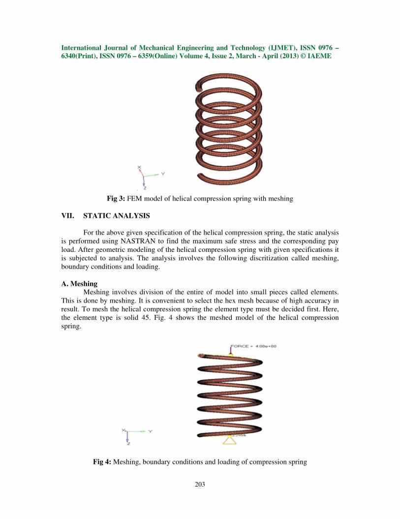
Fig 3: FEM model of helical compression spring with meshing
VII. STATIC ANALYSIS
For the above given specification of the helical compression spring, the static analysis
is performed using NASTRAN to find the maximum safe stress and the corresponding pay
load. After geometric modeling of the helical compression spring with given specifications it
is subjected to analysis. The analysis involves the following discritization called meshing,
boundary conditions and loading.
A. Meshing Meshing involves division of the entire of model into small pieces called elements.
This is done by meshing. It is convenient to select the hex mesh because of high accuracy in
result. To mesh the helical compression spring the element type must be decided first. Here,
the element type is solid 45. Fig. 4 shows the meshed model of the helical compression
spring.
Fig 4: Meshing, boundary conditions and loading of compression spring
International Journal of Mechanical Engineering and Technology (IJMET), ISSN 0976 –
6340(Print), ISSN 0976 – 6359(Online) Volume 4, Issue 2, March - April (2013) © IAEME
204
B. The Following are the Material Properties of the Given Helical Compression Spring Material = Stainless Steel, Young’s Modulus = 193000 N/mm2, Density = 8E-009
tones/mm3, Poisson’s ratio = 0.3 and shear stress = 588.99 N/mm2.
C. Boundary Conditions The helical compression spring is mounted in the horn of the two wheeler automobile.
The casing of the horn is connected to the handle of vehicle. The ends of the helical compression
spring are closed and ground. The helical spring is fixed in between horn button and casing
directly with a frame so that the spring can move longitudinally about the shaft translation is
occurred. The bottom end of the spring is fixed and the other end of the spring is connected to the
button of the vehicle. The horn button has the flexibility to slide along the X-direction when load
applied on the spring and also it can move in longitudinal direction. The spring moves along Y-
direction during load applied and removed. Therefore the nodes of bottom end of the compression
spring are constrained in all translational degrees of freedom. So the top end is constrained as,
UY, ROTY and the nodes of the bottom end are constrained as UY, UZ, UX. Fig. 4 shows the
boundary conditions of the helical compression spring.
D. Loads Applied The load is distributed equally by all the nodes associated with the center of the spring.
The load is applied along FY direction as shown in Fig. 4. To apply load, it is necessary to select
the circumference of the spring centre and consequently the nodes associated with it. It is
necessary to observe the number of nodes associated with the circumference of the spring centre,
because the applied load need to divide with the number of nodes associated with the
circumference of the spring centre.
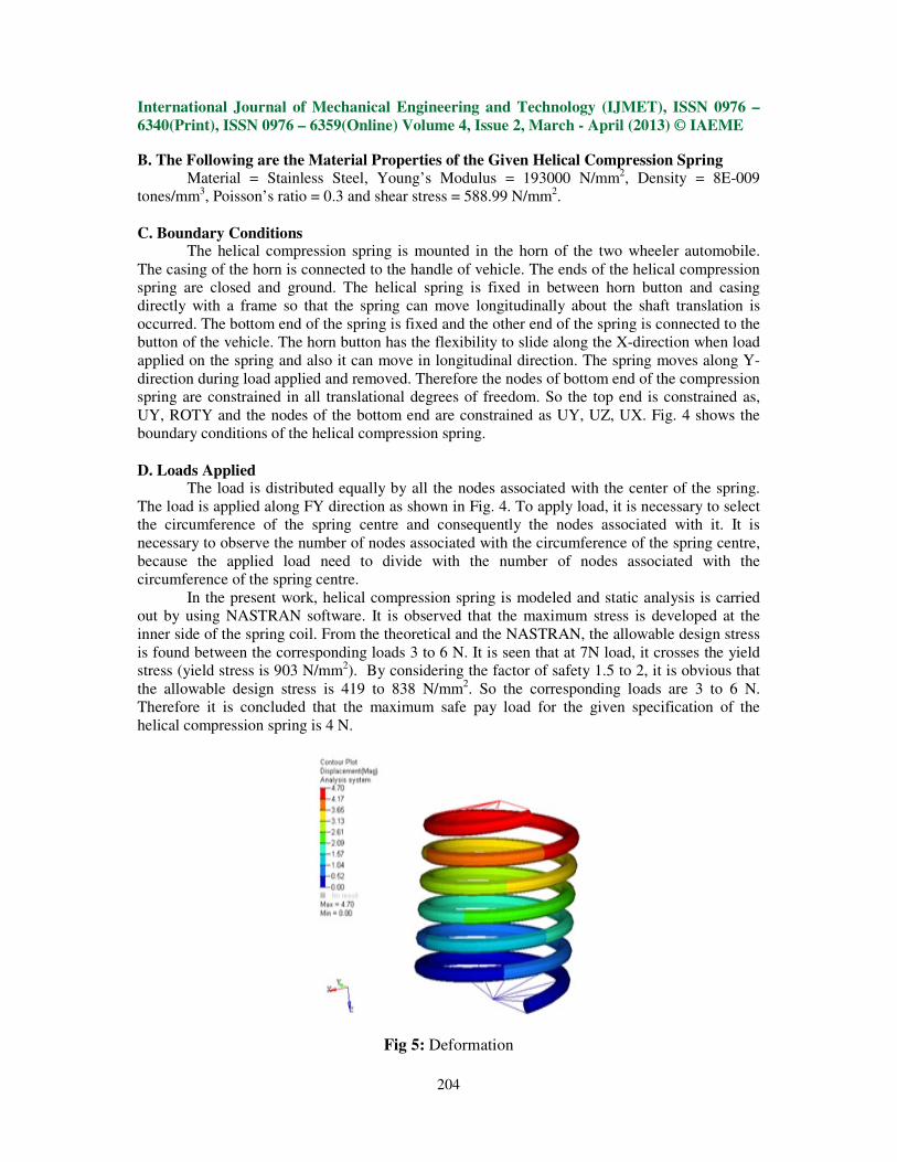
In the present work, helical compression spring is modeled and static analysis is carried
out by using NASTRAN software. It is observed that the maximum stress is developed at the
inner side of the spring coil. From the theoretical and the NASTRAN, the allowable design stress
is found between the corresponding loads 3 to 6 N. It is seen that at 7N load, it crosses the yield
stress (yield stress is 903 N/mm2). By considering the factor of safety 1.5 to 2, it is obvious that
the allowable design stress is 419 to 838 N/mm2. So the corresponding loads are 3 to 6 N.
Therefore it is concluded that the maximum safe pay load for the given specification of the
helical compression spring is 4 N.
Fig 5: Deformation

International Journal of Mechanical Engineering and Technology (IJMET), ISSN 0976 –
6340(Print), ISSN 0976 – 6359(Online) Volume 4, Issue 2, March - April (2013) © IAEME
205
Fig. 6: Maximum Shear Stress at Design Load 4n
From Fig. 5 and Fig. 6, it is obvious that maximum stress developed is at inner side of the spring
sections. The red color indicates maximum stress, because the constraints applied at the interior
of the spring. Since the inner surfaces of the spring are subjected to maximum stress, care must be
taken in spring surface, fabrication and material selection. The material must have good ductility,
resilience and toughness to avoid sudden fracture.
VIII. FATIGUE ANALYSIS OF PRESENT SPRING
Using MSC Fatigue life is analyzed by importing present helical compression spring
which is modeled and static analyzed. The result obtained is as shown in fig. 7. It’s life is found
to be more than 3, 00,000 cycles.
Fig.7: Life

International Journal of Mechanical Engineering and Technology (IJMET), ISSN 0976 –
6340(Print), ISSN 0976 – 6359(Online) Volume 4, Issue 2, March - April (2013) © IAEME
206
IX. STATIC ANALYSIS OF MODIFIED CO- AXIAL TWO WHEELER HORN
SPRING
Similarly, static analysis modified co-axial spring is carried out which is shown in fig.
8. Then importing the same in Msc. Fatigue, fatigue analysis is completed. For modified co-
axial spring also life is found to be infinite.
Fig. 8: Shear Stress Analysis (Max. Shear)
Fig. 9: Life (Max. Shear)
X. EXPERIMENTATION
The standard or reference data available for the past design/ validation as standards or
reference proved to be very useful for experimentation.
The spring design once identified as suitable for the application is subjected to trials for checking
the fatigue life by using MSC. Fatigue experimentation is carried out using a `Life Testing SPM’
of a suitable type and capacity at Kiran Machine Tools Ltd. I- 1, M. I. D. C. area, Jalgaon (MH).
The spring is held in position with other operating conditions identical to the application.

International Journal of Mechanical Engineering and Technology (IJMET), ISSN 0976 –
6340(Print), ISSN 0976 – 6359(Online) Volume 4, Issue 2, March - April (2013) © IAEME
207
The trials are conducted in a very controlled environment with focus on the variables
influencing the fatigue life. A 300000 cycles trial is conducted to ensure consistency/
repeatability of the spring behavior which is shown in fig. 10. Present spring is found to be
safe for 300000 cycles. Fig. 10 shows test report of the same spring.
Fig 10: Test Report of Present Spring
XI. RESULTS AND DISCUSSIONS
From static analysis, the allowable design stress is 419 to 838 N/mm
2. So the
corresponding loads are 3 to 6 N. Hence, analysis is carried at load 4 N.
Life of present spring found to be more than 3, 00,000 cycles using software analysis as well
as experimentally. To extend life in place of present spring co-axial (series) spring is
analyzed and its life is also more than 3, 00,000 cycles.
The inner surfaces of the spring are subjected to maximum stress; care must be taken in
spring surface, fabrication and material selection.
International Journal of Mechanical Engineering and Technology (IJMET), ISSN 0976 –
6340(Print), ISSN 0976 – 6359(Online) Volume 4, Issue 2, March - April (2013) © IAEME
208
For improving fatigue life following methods can be used.
- The most obvious way to improve fatigue life is to design a spring with a lower stress.
- Shotpeening can greatly improve the fatigue life of springs.
- The set taken during pressing must be allowed for in the coiling process so that the
correct loads are obtained after press.
- Upgrade material to a higher tensile range or a higher quality grade.
- The surface of the wire is shaved before the final draw to eliminate surface defects.
- Shock loading and resonance can seriously reduce cycle life.
- Some fatigue problem can be improved by stress corrosion, buckling, coil clash, wear,
non-axial forces, and dynamic loading.
XII. FUTURE SCOPE
Future scope for this study is to study micro-structure, change material of spring
design the same spring.
The inner surfaces of the spring are subjected to maximum stress, care must be taken in
spring surface, fabrication and material selection. The material must have good ductility,
resilience and toughness to avoid sudden fracture.
XII. ACKNOWLEDGMENTS
This study was carried out through a Able Technologies (I) Pvt. Ltd., has sponsored
me this project work. The authors wish to thank Prof. R. R. Deshmukh and Dr. M. S. Kadam
for his helpful advices.
REFERENCES
1 G. Harinath Gowd and E. Venugopal Goud, “Static analysis of leaf spring”, International Journal
of Engineering Science and Technology, Vol. 4, pp. 3794-3803, 2012.
2 Robert Stone, “Fatigue life estimates using Goodman diagrams” ,SMI Encyclopedia of Spring
Design.
3 William H. Skewis, “Failure modes of mechanical springs”, Support Systems Technology
Corporation
4 F. N. Ahmad Refngah et al, “Fatigue life evaluation of two types of steel leaf springs”,
International Journal of Mechanical and Materials Engineering (IJMME), Vol. 4, No. 2, 136-140,
2009
5 Mr. V. K. Aher and Mr. P. M. Sonawane, “Static and fatigue analysis of multi leaf spring used in
the suspension system of LCV”, International Journal of Engineering Research and Applications,
Vol. 2, pp. 786-1791, 2012.
6 Shigley, “Mechanical Engineering Design”, Eighth Edition, Budynas−Nisbett, McGraw−Hill
Primis, 2006, Ch. 10.
7 Vijay Gautam , Parveen Kumar and Aadityeshwar Singh Deo, “Effect of Punch Profile Radius
and Localised Compression on Springback in V-Bending of High Strength Steel and its Fea
Simulation” International Journal of Mechanical Engineering & Technology (IJMET), Volume 3,
Issue 3, 2012, pp. 517 - 530. ISSN Print: 0976 – 6340, ISSN Online: 0976 – 6359.
8 Rakesh Hota, Kshitij Kumar, Ganni Gowtham and Avinash Kumar Kotni, “Experimental
Investigation of Fiberglass Reinforced Mono-Composite Leaf Spring”, International Journal of
Design and Manufacturing Technology (IJDMT), Volume 4, Issue 1, 2013, pp. 30 - 42, Published
by IAEME, ISSN Print: 0976 – 6995, ISSN Online: 0976 – 7002.