international journal of civil … modeling...international journal of civil engineering and...
TRANSCRIPT

International Journal of Civil Engineering and Technology (IJCIET), ISSN 0976 – 6308 (Print),
ISSN 0976 – 6316(Online) Volume 4, Issue 1, January- February (2013), © IAEME
1
NUMERICAL MODELING OF REINFORCED SOIL SEGMENTAL
WALL UNDER SURCHARGE LOADING
Machhindra S.Purkar
1, Sunil Y. Kute
2
K. K. Wagh Institute of Engineering and Research Center, Nashik, Maharashtra, India. 1Research Scholar
2Professor and Head of Research Center.
Correspondence to: M. S. Purkar, India. E-mail: [email protected]
ABSTRACT
This paper outlines the finite element procedure for simulating the performance of a
reinforced soil segmental (modular blocks) wall. Analyses were performed using a software
code which is developed in FORTRAN and validated for reported case histories in the
literature. The material properties of the wall like backfill, foundation, modular concrete
fascia blocks and reinforcement were expressed using linear elastic models. A series of
parametric studies was conducted to identify effects of reinforcement, stiffness and Poison’s
ratio of backfill and foundation strata on the performance of the wall. Increased stiffness of
backfill and foundation improves the performance of the wall by restraining the front face
deformation. The design charts for deflections at top and bottom and also, height of rotation
are developed in the current work by varying the stiffness of backfill and foundation. These
charts are useful to the designer to choose appropriate backfill and also, to ascertain the
suitability of available foundation for the construction of wall, considering codal provisions
regarding deformation limits at the front face of the wall.
Key words: reinforced earth wall; finite element analysis; yielding foundation; serviceability
criteria; uniform surcharge; segmental wall.
1. INTRODUCTION
The reinforced soil structure has gained increasing popularity for replacing the
conventional retaining wall. As a result, various procedures have been proposed for designing
the said structures [1]. However, the currently used design procedures could only be regarded
as semi-empirical. They are mostly based on the limit equilibrium method (LEM) which
INTERNATIONAL JOURNAL OF CIVIL ENGINEERING AND
TECHNOLOGY (IJCIET)
ISSN 0976 – 6308 (Print)
ISSN 0976 – 6316(Online)
Volume 4, Issue 1, January- February (2013), pp. 01-15
© IAEME: www.iaeme.com/ijciet.asp
Journal Impact Factor (2012): 3.1861 (Calculated by GISI)
www.jifactor.com
IJCIET
© IAEME
International Journal of Civil Engineering and Technology (IJCIET), ISSN 0976 – 6308 (Print),
ISSN 0976 – 6316(Online) Volume 4, Issue 1, January- February (2013), © IAEME
2
evaluates the internal and external stabilities of the structures at their ultimate strength
condition. Due to its inability to consider the operational conditions of the structures, such as
the construction sequence, soil structure interaction and load-displacement relationship.
LEM-based design has to be encompassed with high factor of safety. The study by Claybourn
and Wu [2], which evaluated the most commonly used LEM-based design procedures, clearly
demonstrated this fact and it directly reflects our general lack of understanding of the
performance of reinforced soil structures.
When compared with LEM, the finite element method (FEM) more powerful analytical
tool for solving the boundary value problems. It renders informations such as the deformation
and stress-strain distribution in the structure subject to complex geometries, boundary and
loading conditions. These informations are highly required in designing the important civil
engineering structures. Also, the design of any structure needs to consider two limit states,
the serviceability and ultimate limit state. In case of reinforced soil the serviceability is
checked at working conditions to ensure that, it will retain the characteristics necessary for it
to fulfill its function throughout its life without the need for abnormal maintenance. The
ultimate limit state relates to all potential collapse mechanisms that can be identified, to
major damage or deformations in excess of acceptable limits.
Also, the behaviour of a reinforced soil retaining structures constructed on a rigid
foundation has been extensively investigated both experimentally and theoretically in past
and many current design criteria’s are based partly on this research [3-19]. However, the
behaviour of these reinforced soil walls constructed on soft or yielding foundations has
received limited attention [20-30] and many questions still remain as to the performance and
response of these structures. The overall behaviour of a reinforced earth wall constructed on
yielding foundation, including a review of the vertical stress and displacement at the base of
the wall, the horizontal stress behind the wall facing and strain pattern in the reinforcement,
has not been examined. Hence, the current investigation deals with a short-term analysis of a
reinforced soil wall constructed on a yielding foundation and analyses the key factors
influencing the wall behaviour.
2. PARAMETRIC DETAILS
The analysis of reinforced earth wall is carried out by considering the different
parameters which are discussed below.
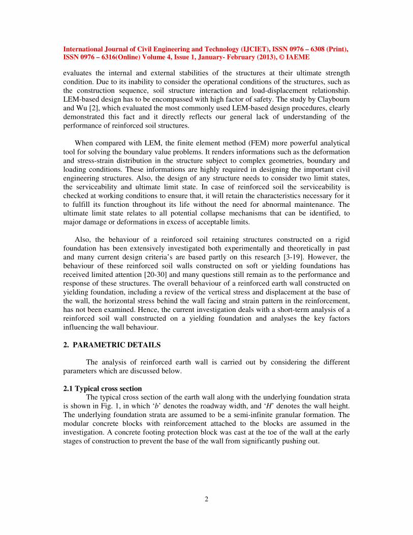
2.1 Typical cross section The typical cross section of the earth wall along with the underlying foundation strata
is shown in Fig. 1, in which ‘b’ denotes the roadway width, and ‘H’ denotes the wall height.
The underlying foundation strata are assumed to be a semi-infinite granular formation. The
modular concrete blocks with reinforcement attached to the blocks are assumed in the
investigation. A concrete footing protection block was cast at the toe of the wall at the early
stages of construction to prevent the base of the wall from significantly pushing out.
International Journal of Civil Engineering and Technology (IJCIET), ISSN 0976 – 6308 (Print),
ISSN 0976 – 6316(Online) Volume 4, Issue 1, January- February (2013), © IAEME
3
Fig. 1 Typical cross-section of reinforced earth wall resting upon the semi infinite foundation strata
2.2 Soil in earth wall
Three types of granular (c-φ ) soils are considered for the construction of the earth
wall. The engineering properties of these three types of embankment (backfill) material are
presented in Table 1. [31].
Table 1. The engineering properties of the backfill material.
Sr.
No.
Soil
designation
Soil modulus,
E (kPa)
Poison’s ratio
(m)
Unit weight,
γ ( KN/m3)
1 E1 1.00E+05 0.300 18.5
2 E2 5.00E+04 0.275 18.0
3 E3 1.00E+04 0.250 17.5
2.3 Soil in the Foundation Strata Six types of soil are considered in the foundation strata. The engineering properties of
these six types of soil are presented in Table 2. [31].
Table 2. The engineering properties of the soils constituting foundation strata.
Sr. No. Soil
designation
Soil modulus,
E (kPa) Soil density, γ
( KN/m3)
Poison’s ratio (m)
1 2 3 4 5
1 F1 1.00E+02 16.5 For each value of ‘E’
shown in column-03, three
values of Poison’s ratio of
foundation strata namely
0.30, 0.35, and 0.40 are
considered.
2 F2 1.00E+03 17.0
3 F3 1.00E+04 17.5
4 F4 1.00E+05 18.0
5 F5 1.00E+06 18.5
6 F6 1.00E+07 19.0

International Journal of Civil Engineering and Technology (IJCIET), ISSN 0976 – 6308 (Print),
ISSN 0976 – 6316(Online) Volume 4, Issue 1, January- February (2013), © IAEME
4
2.4 Steel reinforcement
The reinforcement considered in the analysis is galvanized iron strips of 4 cm wide
and sectional area of 1.0 cm2 placed at 50 cm vertical spacing. The elastic properties of
reinforcement assumed in the analysis are: modulus of elasticity (E) 200 GPa, and poison’s
ratio (m) 0.30. [32-33].
2.5 Fascia modular concrete blocks A vertical column of the modular concrete blocks as a fascia element is provided to
support the reinforced system. The fascia element is 20.0cm thick with a concrete of the
grade M25, hence its material properties are: E=2.5x10⁷ kPa, γ =25 Kn/m
3 and µ=0.15 [16].
2.5 Surcharge loading (q)
A uniform surcharge of magnitude 40 kPa for the considerations to the additional
traffic road, extending over the full width of roadway is considered in the analysis [34].
3. FINITE ELEMENT IDEALIZATION
The software developed in FORTRAN for the analysis of reinforced earth retaining
wall and tested for reported case histories in the literature is used to conduct the numerical
analysis. The reinforced earth wall with modular fascia concrete blocks was idealized as two-
dimensional and a plain-strain FE analysis was performed.
From Fig. 1, it is easy to recognize that the system under consideration has a vertical axis of
symmetry; hence, it is adequate to analyze only half section as shown in Fig. 2. The
boundaries of the section being investigated are based on the following assumptions.
i) The boundary defined by the vertical axis of symmetry represents a boundary with
horizontal displacement being restrained.
ii) The infinite domain of the foundation strata is curtailed vertically at a depth ‘D’, and the
boundary so formed is assumed to be restrained horizontally as well as vertically.
iii) The infinite lateral boundary of the foundation strata on the left is curtailed at a distance
‘L’, and resulting boundary is assumed to be restrained in horizontal direction.
The zone so developed is idealized through square elements of size 0.5m by 0.5m. The
backfill of earth wall and foundation soil have been discretized using 2D four nodded
isoparametric plane strain quadrilateral element. The geometry nodal point locations, loading
and the coordinate system for this element are shown in Fig. 3. Every element is defined by
four nodal points having two degrees of freedom at each node, i.e. translation in X and Y
directions. A unit thickness is assumed for the element. The material properties as a input for
this element, for isotropic elastic case, are soil modulus ‘E’, Poison’s ratio ‘m’ and soil
density ‘γ ’.
The reinforcing elements have been modeled as two-dimensional line element. It is uniaxial
tension/compression element with two degrees of freedom at each node (Translation in nodal
X and Y directions). No bending of element is considered. The element is defined by two
nodal points. The cross sectional area, and material properties (E, m) are the input for this
element. The displacement direction for the line element is assumed to be linear.
The fascia element have the behavior of that of an articulated column, hence it is represented
through two nodded elements with only axial mode of deformation. In addition for in depth
investigation between the line elements representing the fascia elements and the adjoining
wall surface, the interface elements are incorporated. As the fascia elements are line elements,

International Journal of Civil Engineering and Technology (IJCIET), ISSN 0976 – 6308 (Print),
ISSN 0976 – 6316(Online) Volume 4, Issue 1, January- February (2013), © IAEME
5
the poisons ratio (µ) does not appear in the formation of the element characteristics. Pilot run of the
problems indicate that for a wide range of the interface moduli (Ks, Kn); the response is more or less
unaffected. Hence the following typical values for them are assumed in the current investigations for
the formulations of interface element i.e. Ks=90 kPa and Kn=60 kPa.
It was found that, the common approach of providing equally spaced truncated reinforcement with
reinforcement length (L) to wall height (H) ratio, L/H equal to 0.7, provides a relatively efficient
distribution of reinforcement force. In contrast, the approach of varying reinforcement spacing in an
attempt to mimic the horizontal stress distribution provided to be less efficient and is not
recommended. Varying reinforcement length, i.e. reinforcement extended to the zero force line, did
not provide any significant improvement in force distribution relative to the truncated reinforcement
of L/H=0.7. Hence, in the current investigation, the minimum ratio L/H=0.7 is maintained [35-36].
Fig. 2 The details of symmetrical section considered in the analysis
Fig. 3 Finite element idealization for reinforced wall system with modular concrete fascia blocks

International Journal of Civil Engineering and Technology (IJCIET), ISSN 0976 – 6308 (Print),
ISSN 0976 – 6316(Online) Volume 4, Issue 1, January- February (2013), © IAEME
6
3.1 Details of Idealization Scheme
Full information of the idealized system, considered in analysis is presented in Table
3. The details of the four material types presented in Table 3 are, backfill material used for
the construction of earth wall, foundation material assumed below the earth wall, the steel
reinforcement used as reinforcement in the earth wall and the modular concrete blocks used
to support the fascia of the wall.
Table 3. Details of finite element idealization scheme
Sr.
N
o.
H(
m)
b(m) Number of elements Total
no. of
eleme
nts
Tota
l no.
of
node
s
Total
no. of
bound
ary
nodes
Backfi
ll
Foundati
on
Reinfo
r-
cemen
t
Fascia wall
Line
eleme
nt
Interfa
ce
eleme
nt
1 7.
5
12.0 180 855 156 15 15 1221 1123 103
4. FINITE ELEMENT ANALYSIS
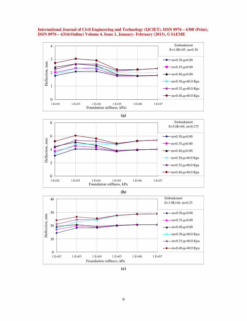
The reinforced earth wall is discretized as discussed in section 3. The parametric
investigations are carried out by varying the properties (vide Table 1 and Table 2) of
embankment and foundation strata. The response derived for deflected front face profile of
wall for wall height 7.5m and roadway width 12.0m, considering self-weight of wall are
presented in Figs. 4a-i. The modulus of elasticity of reinforcement equal to 200 GPa and
sectional area of 1.0cm2
is kept constant for all investigations.
The stiffness values of backfill and foundation are expressed in ‘kPa’ as shown in Figs. 4a-i.
Each figure shows the variation of front face deflections for a particular value of stiffness
(kPa) and Poison’s ratio of embankment and by varying the stiffness of foundation strata to
seven types and keeping Poison’s ratio of foundation constant as shown in legend. The
outward deflections from the vertical line of the wall at the base are plotted as negative values
and inward deflections at the top are plotted as positive values.
0
2
4
6
8
-5 0 5Deflection, mm
Heig
ht
of
wal
l, m
.
E=1.00E+02
E=1.00E+03
E=1.00E+04
E=1.00E+05
E=1.00E+06
E=1.00E+07
Embankment
E=1.00E+05
m=0.30
Foundation
m=0.30
0
2
4
6
8
-5 0 5Deflection, mm
Hei
gh
t of
wal
l, m
.
E=1.00E+02
E=1.00E+03
E=1.00E+04
E=1.00E+05
E=1.00E+06
E=1.00E+07
Embankment
E=1.00E+05
m=0.30
Foundation
m=0.35
(a) (b)

International Journal of Civil Engineering and Technology (IJCIET), ISSN 0976 – 6308 (Print),
ISSN 0976 – 6316(Online) Volume 4, Issue 1, January- February (2013), © IAEME
7
0
2
4
6
8
-5 0 5Deflection, mm
Hei
gh
t of
wall
, m
.
E=1.00E+02
E=1.00E+03
E=1.00E+04
E=1.00E+05
E=1.00E+06
E=1.00E+07
Embankment
E=1.00E+05
m=0.30
Foundation
m=0.40
0
2
4
6
8
-8 -4 0 4 8Deflection, mm
Hei
gh
t o
f w
all,
m.
E=1.00E+02
E=1.00E+03
E=1.00E+04
E=1.00E+05
E=1.00E+06
E=1.00E+07
Embankment
E=5.00E+04
m=0.275
Foundation
m=0.30
(c) (d)
0
2
4
6
8
-8 -4 0 4 8Deflection, mm
Hei
ght
of
wall
, m
.
E=1.00E+02
E=1.00E+03
E=1.00E+04
E=1.00E+05
E=1.00E+06
E=1.00E+07
Embankment
E=5.00E+04
m=0.275
Foundation
m=0.35
0
2
4
6
8
-8 -4 0 4 8
Deflection, mm
Heig
ht
of
wal
l, m
.
E=1.00E+02
E=1.00E+03
E=1.00E+04
E=1.00E+05
E=1.00E+06
E=1.00E+07
Embankment
E=5.00E+04
m=0.275
Foundation
m=0.40
(e) (f)
0
2
4
6
8
-30 -15 0 15 30Deflection, mm
Heig
ht
of
wall
, m
.
E=1.00E+02
E=1.00E+03
E=1.00E+04
E=1.00E+05
E=1.00E+06
E=1.00E+07
Embankment
E=1.00E+04
m=0.25
Foundation
m=0.30
0
2
4
6
8
-30 -15 0 15 30Deflection, mm
Heig
ht
of
wall
, m
.
E=1.00E+02
E=1.00E+03
E=1.00E+04
E=1.00E+05
E=1.00E+06
E=1.00E+07
Embankment
E=1.00E+04
m=0.25
Foundation
m=0.35
(g) (h)
Fig. 4 (a-i) Response details of front face deflected profile of earth wall for H=7.5m, b=12m

International Journal of Civil Engineering and Technology (IJCIET), ISSN 0976 – 6308 (Print),
ISSN 0976 – 6316(Online) Volume 4, Issue 1, January- February (2013), © IAEME
8
4.1 Wall resting on weak foundation
The results presented in Figs. 4a-i, show that, so long as the foundation stiffness
represented by the value of ‘E’ is less than that of backfill (i.e. wall resting on weak
foundation), the vertical face of the wall deflects in a manner which is shown schematically
in Fig. 5a. The deflected profile as shown in Fig. 5a. is characterized by inward deflection at
the top of the wall and outward deflection at the base; thereby, it has point of rotation over
the wall height. The profile shape is approximately parabolic and if, its theoretical details are
required, then over the data, the parabolic expression could be fitted by considering the point
of rotation and its location and the amount of deflection at the top and the base of the wall.
Hence to define the complete behavior of deflected profile, it needs to define the maximum
deflection at top and base and also the height of rotation.
0
2
4
6
8
-10 -5 0 5 10Deflection, mm
Heig
ht
of
wal
l, m
E=1.00E+03
Embankment
E=5.00E+04
m=0.275
Foundation
m=0.40
0
2
4
6
8
-10 -5 0 5 10Deflection, mm
Hei
gh
t o
f w
all,
m
E=1.00E+07
Embankment
E=5.00E+04
m=0.275
Foundation
m=0.40
(a) (b) Fig. 5. Response of wall. (a) resting on weak foundation and (b) resting on strong foundation
4.2 Wall resting on strong foundation In case of the foundation soil having value of stiffness ‘E’ equal to or more than that
of the reinforced backfill (i.e. wall resting on strong foundation), it is observed that, the
deflection at the top is in the inward direction and significant and the deflection at the base is
almost zero. Thereby, it has point of rotation over the wall height. The profile shape is
approximately parabolic. The apex of the parabola defines the maximum outward deflection
suffered by the wall (Fig. 5b). Hence for strong foundation to check the codal serviceability
requirement, the deflections at top, deflection at bulge and its location is necessary. The
maximum deflections at bulge and its location for various wall heights will be reported in the
next paper (part-II).
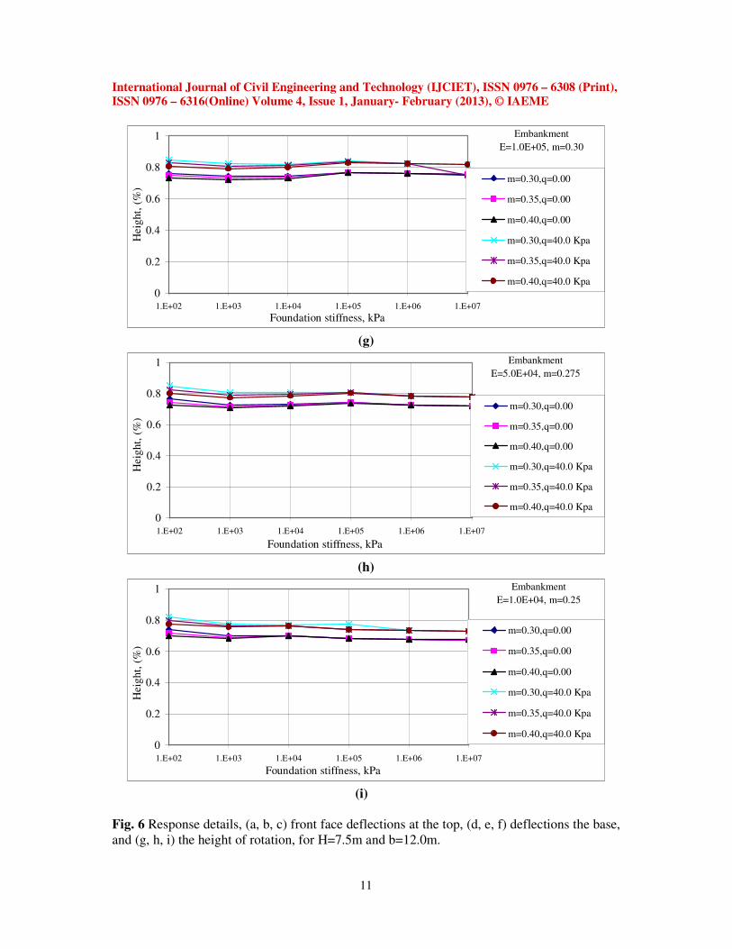
As reported in section 4, the analysis of reinforced earth wall is carried out for self-weight, is
also carried out for a uniform surcharge of 40 kPa extending over a full width of the wall.
The front face deflections at top and base and the height of rotation from base in percentage
height are plotted in Figs. 6a-i, for the entire range of three types of embankment and seven
types of foundations. In each Figure the stiffness and Poison’s ratio of embankment is kept
constant. Front face deflections are plotted by varying the stiffness of foundation to six types.
First three series shows the variation of front face deflections by varying Poison’s ratio of
foundation to 0.30, 0.35 and 0.40 for self-weight of the wall. Next three series shows the
variation of front face deflections by varying the Poison’s ratio of foundation to 0.30, 0.35
and 0.40 for a constant surcharge of 40 kPa extended over full width of the wall.
International Journal of Civil Engineering and Technology (IJCIET), ISSN 0976 – 6308 (Print),
ISSN 0976 – 6316(Online) Volume 4, Issue 1, January- February (2013), © IAEME
9
0
1
2
3
4
1.E+02 1.E+03 1.E+04 1.E+05 1.E+06 1.E+07
Foundation stiffness, kPa)
Defl
ect
ion
, m
m. m=0.30,q=0.00
m=0.35,q=0.00
m=0.40,q=0.00
m=0.30,q=40.0 Kpa
m=0.35,q=40.0 Kpa
m=0.40,q=40.0 Kpa
Embankment
E=1.0E+05, m=0.30
(a)
0
2
4
6
8
1.E+02 1.E+03 1.E+04 1.E+05 1.E+06 1.E+07
Foundation stiffness, kPa
Defl
ecti
on
, m
m. m=0.30,q=0.00
m=0.35,q=0.00
m=0.40,q=0.00
m=0.30,q=40.0 Kpa
m=0.35,q=40.0 Kpa
m=0.40,q=40.0 Kpa
Embankment
E=5.0E+04, m=0.275
(b)
0
10
20
30
40
1.E+02 1.E+03 1.E+04 1.E+05 1.E+06 1.E+07
Foundation stiffness, kPa
Defl
ecti
on
, m
m. m=0.30,q=0.00
m=0.35,q=0.00
m=0.40,q=0.00
m=0.30,q=40.0 Kpa
m=0.35,q=40.0 Kpa
m=0.40,q=40.0 Kpa
Embankment
E=1.0E+04, m=0.25
(c)

International Journal of Civil Engineering and Technology (IJCIET), ISSN 0976 – 6308 (Print),
ISSN 0976 – 6316(Online) Volume 4, Issue 1, January- February (2013), © IAEME
10
-6
-4
-2
0
1.E+02 1.E+03 1.E+04 1.E+05 1.E+06 1.E+07
Foundation stiffness, kPa
Def
lect
ion
, m
m.
m=0.30,q=0.00
m=0.35,q=0.00
m=0.40,q=0.00
m=0.30,q=40.0 Kpa
m=0.35,q=40.0 Kpa
m=0.40,q=40.0 Kpa
Embankment
E=1.0E+05, m=0.30
(d)
-8
-6
-4
-2
0
1.E+02 1.E+03 1.E+04 1.E+05 1.E+06 1.E+07
Foundation stiffness, kPa
Defl
ecti
on
, m
m. m=0.30,q=0.00
m=0.35,q=0.00
m=0.40,q=0.00
m=0.30,q=40.0 Kpa
m=0.35,q=40.0 Kpa
m=0.40,q=40.0 Kpa
Embankment
E=5.0E+04, m=0.275
(e)
-20
-10
0
10
20
1.E+02 1.E+03 1.E+04 1.E+05 1.E+06 1.E+07
Foundation stiffness, kPa
Def
lect
ion,
mm
. m=0.30,q=0.00
m=0.35,q=0.00
m=0.40,q=0.00
m=0.30,q=40.0 Kpa
m=0.35,q=40.0 Kpa
m=0.40,q=40.0 Kpa
Embankment
E=1.0E+04, m=0.25
(f)
International Journal of Civil Engineering and Technology (IJCIET), ISSN 0976 – 6308 (Print),
ISSN 0976 – 6316(Online) Volume 4, Issue 1, January- February (2013), © IAEME
11
0
0.2
0.4
0.6
0.8
1
1.E+02 1.E+03 1.E+04 1.E+05 1.E+06 1.E+07
Foundation stiffness, kPa
Heig
ht,
(%
)
m=0.30,q=0.00
m=0.35,q=0.00
m=0.40,q=0.00
m=0.30,q=40.0 Kpa
m=0.35,q=40.0 Kpa
m=0.40,q=40.0 Kpa
Embankment
E=1.0E+05, m=0.30
(g)
0
0.2
0.4
0.6
0.8
1
1.E+02 1.E+03 1.E+04 1.E+05 1.E+06 1.E+07
Foundation stiffness, kPa
Heig
ht,
(%
)
m=0.30,q=0.00
m=0.35,q=0.00
m=0.40,q=0.00
m=0.30,q=40.0 Kpa
m=0.35,q=40.0 Kpa
m=0.40,q=40.0 Kpa
Embankment
E=5.0E+04, m=0.275
(h)
0
0.2
0.4
0.6
0.8
1
1.E+02 1.E+03 1.E+04 1.E+05 1.E+06 1.E+07
Foundation stiffness, kPa
Heig
ht,
(%
)
m=0.30,q=0.00
m=0.35,q=0.00
m=0.40,q=0.00
m=0.30,q=40.0 Kpa
m=0.35,q=40.0 Kpa
m=0.40,q=40.0 Kpa
Embankment
E=1.0E+04, m=0.25
(i)
Fig. 6 Response details, (a, b, c) front face deflections at the top, (d, e, f) deflections the base,
and (g, h, i) the height of rotation, for H=7.5m and b=12.0m.

International Journal of Civil Engineering and Technology (IJCIET), ISSN 0976 – 6308 (Print),
ISSN 0976 – 6316(Online) Volume 4, Issue 1, January- February (2013), © IAEME
12
The observations noted from Figs. 6a-i, show that, the response derived for the 7.50m wall
height and 12.0m road width, for above parametric investigation, with self-weight as well as
with a surcharge of 40.0 kPa remains same. But the magnitudes of inward front face
deflections at top, in case of weak foundation increase by 30% to 40% due to surcharge and
for strong foundation the front face deflections at top are also, inward and they increase 50%
to 60%.due to surcharge. The outward front face deflections at base for weak foundation
increase by 30% to 40%.due to surcharge and for strong foundation they tend to zero. For
weak foundation, the front face deflections are sensitive to Poison’s ratio, but for strong
foundation, they are insensitive to Poison’s ratio.
The height of rotation which is expressed in terms of percentage wall height is observed to
be almost constant for weak and strong foundation and it varies from 70% to 75% for self-
weight of wall and 75% to 85% for a surcharge of 40kPa.
11. SUMMARY AND CONCLUSIONS
The physical data presented in this paper and the lessons learnt after investigating the
response of a reinforced soil with segmental wall are of value to researchers engaged in
developing better understanding of reinforced soil wall behavior. Specific important
conclusions in this regard are summarized below.
1. When the wall resting on strong foundation, the rotation of reinforced earth wall is
observed at a particular height, imparting inward deflection at the top of wall and outward
deflection at the base of wall.
2. In case of wall resting on strong foundation also, the rotation of reinforced earth wall is
observed at a particular height. But, inward deflection at the top of wall is significant and
the deflection at the base of wall tends to zero.
3. In case of weak foundation, the response of the wall is sensitive to Poison’s ratio. The
front face deflections are changing as the Poison’s ratio increases. But for strong
foundation, the response is insensitive to Poison’s ratio.
4. Design correlations have been plotted using finite element method for three
types of embankments and seven types of foundation strata for different parameters
like, deflections at top, deflections at base, height of rotation.. This will help the
designer to choose appropriate backfill and also, to ascertain the suitability of foundation
for the construction of wall considering codal provisions regarding deformation limits at
the front face of the wall.
REFERENCES
1. B R Christopher and D Leshchinsky. ‘Design of geosynthetically reinforced slopes’.
Proceedings of ASCE Geotechnical Engineering Congress, Boulder, 1991, pp. 988-1005.
2. A F Claybourn and J T H Wu. ‘Case history comparison of geoynthetic-reinforced soil
walls’. Proceedings of Geosynthetic, 91 Conference, 1991, pp. 549-559.
3. R J Bathurst, W F Wawrychuk, P M Jarret. ‘Laboratory investigation of two large-scale
geogrid reinforced soil walls’. In: Jarret, P. M., McGown, A. (Eds), The application of
polymetric reinforcement in soil retaining structures. Kluwer Academic Publishers,
Dordrecht, 1988, pp. 71-125.

International Journal of Civil Engineering and Technology (IJCIET), ISSN 0976 – 6308 (Print),
ISSN 0976 – 6316(Online) Volume 4, Issue 1, January- February (2013), © IAEME
13
4. R J Bathurst, D J Benjamin, P M Jarrett ‘.An instrumented geogrid reinforced soil wall’.
Twelfth International Conference on Soil Mechanics and Foundation Engineering, Rio de
Janeiro, August 1989, Balkema, Rotterdam/ Brookfield, 1989, pp. 1223-1226.
5. R J Bathurst and D J Benjamin. ‘Failure of geogrid-reinforced soil wall’. Transportation
Research Record 1288, pp. 109-116.
6. K Karpurapu and R J Bathurst. ‘Analysis of geosynthetic reinforced soil wall by the finite
element method’. Fourth International Conference on Numerical Models in
Geomechanics: NUMOG 4, Swansea, U.K., 24-27 August 1992. Balkema,
Rotterdam/Brookfield, 1992, pp. 861-870.
7. J T H Wu. ‘Measured behaviour of the Denver walls’. International Symposium on
Geosynthetic-Reinforced soil walls, Denver, Colrado, USA, 8-9 August 1991. Balkema,
Rotterdam/Brookfield, 1992a, pp. 31-42
8. J T H Wu. ‘Predicting performance of the Denver walls: General Report. International
Symposium on Geosynthetic-Reinforced soil walls, Denver, Colorado, USA, 8-9 August
1991. Balkema, Rotterdam/Brookfield, 1992b, pp. 3-20.
9. S K P Ho. ‘A numerical investigation in to the behaviour of reinforced soil walls’. Ph. D.
Thesis, The University of Western Ontario, Londan, Ontario, Canada, 1993.
10. R K Rowe and S K P Ho. ‘A review of the behaviour of reinforced soil walls’. In: Ochiai,
H., Hayashi, S., Otani, J. (Eds), Earth Reinforcement. Balkema, Rotterdam/Brookfield,
1993, pp. 801-830.
11. R K Rowe and S K P Ho. ‘Some insights into reinforced wall behaviour on finite element
analysis’. In: Ochiai, H., Yasufuku, N., Omine, K. (Eds), Earth Reinforcement. Balkema,
Rotterdam/Brookfield, 1996, pp. 485-490.
12. R J Bathurst and M R Simac. ‘Geosynthetic reinforced segmental retaining wall
structures in North America’. Fifth International Conference on Geotextiles,
Geomembranes and related products, Singapore, 5-9 September 1994. Southeast Asia
Chapter of the International Geotextiles Society, 1994, pp. 1275-1298.
13. R L Michalowski. ‘Limit analysis in stability calculations of reinforced soil structures’.
Geotextiles and Geomembranes, vol. 16, no. 6, pp. 311-331.
14. S M B Helwany, G Reardon, J T H Wu. ‘Effects of backfill on the performance of GRS
retaining walls’. Geotextiles and Geomembranes, vol. 17, no. 1, 1999, pp. 1-6.
15. A Porbaha, A Zhao, M Kabayashi, T Tishida. ‘Upper bound estimate of scaled reinforced
retaining walls’. Geotextiles and Geomembranes, vol. 18, no. 6, 2000, pp. 403-413.
16. C S Desai and Khaled E. EI-Hoseiny. ‘Prediction of field behaviour of reinforced soil
wall using advanced constitutive model’. J. of Geotech. and Geoenvironmential Engg.,
vol. 131, no. 6, 2005, pp. 729-739.
17. .K Hatami and R J Bathurst. ‘Numerical model to reinforced soil segmental walls under
surcharge loading’. J. of Geotech. and Geoenvironmental Engg., vol. 132, no. 6, 2006, pp.
673-684.
18. G Q Yang, B Zhang, P Lv, Q Y Zhou. ‘Behaviour of geogrid reinforced soil retaining
wall with concrete-rigid facing’. Geotextiles and Geomembranes, vol. 27, 2009, pp. 350-
356.
19. J Han and D Leshchinsky. ‘Analysis of back to back mechanically stabilized earth walls’.
Geotextiles and Geomembranes, vol. 28, 2010, pp. 262-267.
20. J R Bell, R K Barrett, A C Ruckman. ‘Geotextile earth-reinforced retaining wall tests:
Glenwood Canyon, Colorado’. Transportation Research Record, PP. 59-69.

International Journal of Civil Engineering and Technology (IJCIET), ISSN 0976 – 6308 (Print),
ISSN 0976 – 6316(Online) Volume 4, Issue 1, January- February (2013), © IAEME
14
21. G R Schmertmann, S H Chew, J K Mitchell. ‘Finite element modeling of reinforced soil
wall behaviour’. Department of Civil Engineering, University of California, Berkely,
Geotechnical Engineering Report No. UCB/GT/ 89-01, 1989.
22. D T Bergado, R Shivashankar, C L Sampaco, M C Alfaro, L R Anderson. ‘Behaviour of a
welded wire wall with poor quality, cohesive-friction backfill on soft Bangkok clay: a
case study’. Canadian Geotechnical Journal, vol. 28, pp. 860-880.
23. D T Bergado, N T L Menil, R Rimoldi, R S Douglas. ‘Performance of full scale
embankment on soft Bangkok clay with geogrid reinforcement’. Fifth International
Conference on Geotextiles, Geomembranes and related products, Singapore, 5-9
September 1994. Southeast Asia chapter of the International Geotextiles Society, 1994,
pp. 1-4.
24. N N S Chau. ‘Performance of geosynthetic reinforced soil walls’. Ph.D. Thesis,
University of Colorado at Boulder, Colorado, U.S.A., 1992.
25. E M Palmeria and L M Monte. ‘The behaviour of model reinforced walls on soft soils.
Geosynthetics, 97, Long Beach California, USA, 11-13 March 1997’. Industrial Fabrics
Association International, 1997, pp. 73-84.
26. J Otani, T Hirai, H Ochiai, S Shinowaki. ‘Evaluation of foundation support for
geosynthetic reinforced soil wall on sloping ground’. Sixth International Conference on
Geosynthetics, Atlanta, USA, 25-29 March 1998. Industrial Fabrics Association
International, 1998, pp. 601-603.
27. R K Rowe and G D Skinner. ‘Numerical analysis of geosynthetic reinforced retaining
wall constructed on a layered soil foundation’. Geotextiles and Geomembranes, vol. 19,
2001, pp. 387-412.
28. D T Bergado, S Youwai, C Teerawattanasuk, P Visudmedanukul. ‘The interaction
mechanism and behaviour of hexagonal wire mesh reinforced embankment with silty
sand backfill on soft clay’. Computers and Geotechnics, vol. 30, 2003, pp. 517-534.
29. R K Rowe and G D Skinner. ‘Design and behaviour of a geosynthetic reinforced retaining
wall and bridge abutment on a yielding foundation’. Geotextiles and Geomembranes,
2005, vol. 23, 2005, pp. 234-260.
30. D T Bergado, C Teerawattanasuk. ‘2D and 3D numerical simulations of reinforced
embankment on soft ground’. Geotextiles and Geomembranes, vol. 26, 2008, pp. 39-55.
31. T W Lambe and R V Whitman. ‘Soil Mechanics’. John Wiley, 1969, pp. 353-373.
32. R J Bathurst, T M Allen, D L Walters. ‘Reinforcement loads in geosynthetic walls and the
case for a new working stress design method (Mercer Lecture)’. Geotextile
Geomembrane, vol. 23, no. 4, 2005, pp. 287-322.
33. A Bayoumi, A Bobet, J Lee. ‘Pullout capacity of a reinforced soil in drained and
undrained condition’. Finite Element in Analysis and Design, vol. 44, 2008, pp. 525-536.
34. IRC: 6- (1966). ‘Standard specifications and code of practice for roads and bridges,
section II, loads and stresses, Reprint’. 1994, pp. 1-37.
35. Swami Saran, K G Gerg, R J Bathurst. ‘Retaining wall with reinforced cohesionless
backfill’. J. Geotech. Eng., ASCE, vol. 118, no. 12, 1992, pp. 1869-1889.
36. S K Ho and R K Row.’Effect of wall geometry on the behavior of reinforced soil walls’.
Geotextile Geomembrane, vol. 14, no. 10, 1996, pp. 521-541.
37. V.K.Chakravarth, K.Ramu and M.R.Madhav, “Slope Stability Analysis of Basal
Reinforced Embankment under Oblique Pull” International Journal of Civil Engineering
& Technology (IJCIET), Volume1, Issue1, 2010, pp. 1 - 14, Published by IAEME

International Journal of Civil Engineering and Technology (IJCIET), ISSN 0976 – 6308 (Print),
ISSN 0976 – 6316(Online) Volume 4, Issue 1, January- February (2013), © IAEME
15
38. S.R.Debbarma and S.Saha, “An Experimental Study on Growth of Time-Dependent
Strain in Shape Memory Alloy Reinforced Concrete Beams and Slabs” International
Journal of Civil Engineering & Technology (IJCIET), Volume3, Issue2, 2012,
pp. 108 - 122, Published by IAEME
39. Misam.A and Mangulkar Madhuri.N., “Structural Response of Soft Story-High Rise
Buildings under Different Shear Wall Location” International Journal of Civil
Engineering & Technology (IJCIET), Volume3, Issue2, 2012, pp. 169 - 180, Published by
IAEME
40. Wani Ahmad and Javed Ahmad Bhat, “Pre-Tensioned Precast Elements as A
Replacement to Wooden Bracings in the Armature Cross Wall System: An Abstract
Attempt to Revive the Forgotten Heritage” International Journal of Civil Engineering &
Technology (IJCIET), Volume3, Issue2, 2012, pp. 181 - 187, Published by IAEME