international competitive bidding - :: पिंपरी ... icb for structure... · ramps on...
TRANSCRIPT
PawanaRiver
18m DP Road
PIMPRI- CHINCHWADMUNICIPAL CORPORATION
PIMPRI- CHINCHWADMUNICIPAL CORPORATION
PIMPRI, PUNE- 18
INVITES BIDS FOR INVITES BIDS FOR
INTERNATIONAL COMPETITIVE BIDDINGINTERNATIONAL COMPETITIVE BIDDING
VOLUME - IIVOLUME - II
Design and Construction of Bridge on Pawana River,Flyover/Viaduct and ROB with Approaches &
Ramps on Kalewadi Phata to Dehu Alandi Road.
Pimpri Chinchwad Municipal Corporation Name of work: Design and Construction of Bridge on Pawana River, Flyover/Viaduct and ROB with Approaches & Ramps on Kalewadi Phata to Dehu Alandi Road.
Contractor Exe. Engineer PCMC
INTERNATIONAL COMPETITIVE BIDDING
Design and Construction of Bridge on Pawana River, Flyover/Viaduct and ROB with Approaches & Ramps on Kalewadi Phata to Dehu Alandi
Road.
VOLUME – II
Pimpri Chinchwad Municipal Corporation
Pimpri, Pune – 411 018.
May–2010
Page 1

P i mp r i C h i n c h w a d M u n i c i p a l C o r p o r a t i o n Name of work: Design and Construction of Bridge on Pawana River, Flyover/ Viaduct and ROB with Approaches & Ramps on Kalewadi Phata to Dehu Alandi Road.
Contractor Exe. Engineer ( PCMC
Design and Construction of Bridge on Pawana River, Flyover/Viaduct and ROB with Approaches & Ramps on Kalewadi Phata to Dehu Alandi Road. Estate.
VOLUME II
SECTION VI
Employers Requirements
INDEX
Chapter Particulars Page No.
I Preamble 4 - 7
II Employers Requirements in Details 8 – 25
III Design Criteria for Highways and General Obligatory requirements
26 – 35
IV Design Criteria for Structures and General Obligatory requirements
36 – 67
V Special Conditions of Contract 68 – 74
Page 2
P i mp r i C h i n c h w a d M u n i c i p a l C o r p o r a t i o n Name of work: Design and Construction of Bridge on Pawana River, Flyover/ Viaduct and ROB with Approaches & Ramps on Kalewadi Phata to Dehu Alandi Road.
Contractor Exe. Engineer ( PCMC
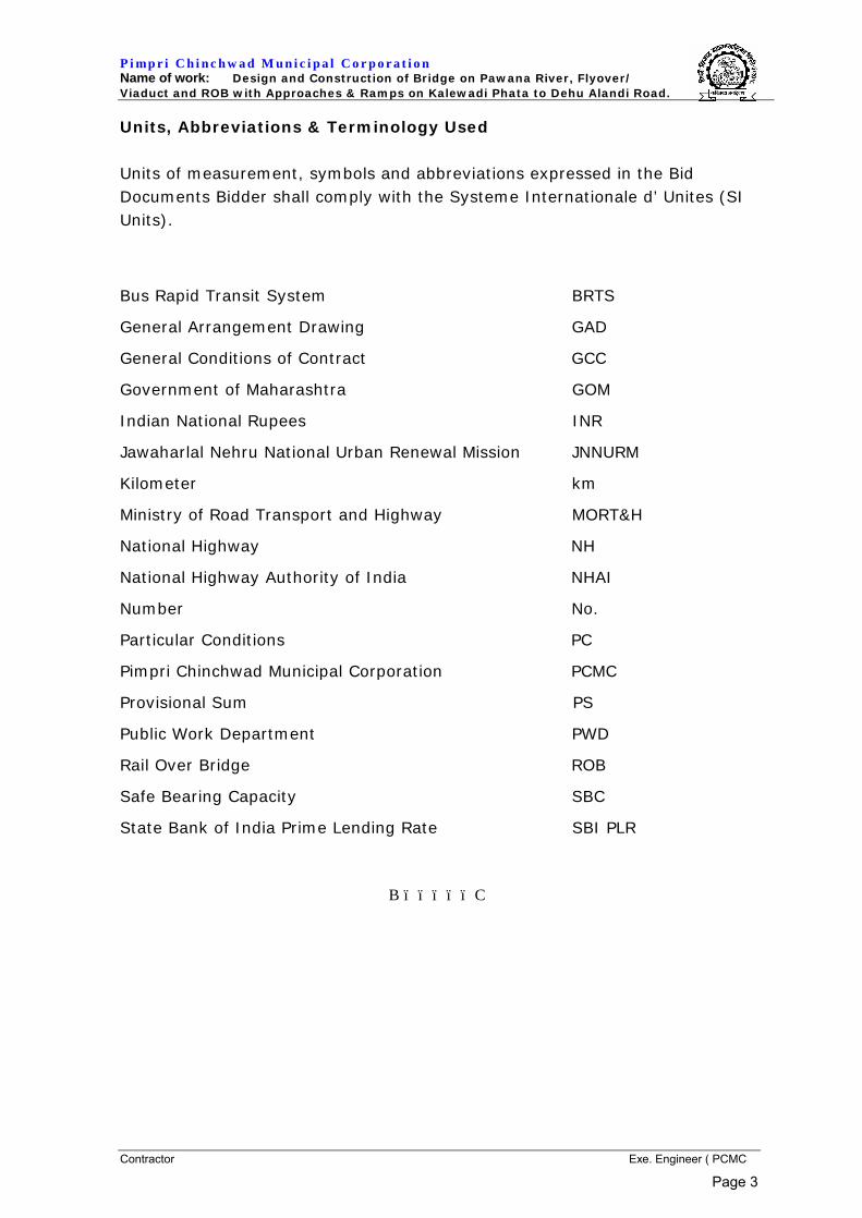
Units, Abbreviations & Terminology Used Units of measurement, symbols and abbreviations expressed in the Bid Documents Bidder shall comply with the Systeme Internationale d’ Unites (SI Units).
Bus Rapid Transit System BRTS
General Arrangement Drawing GAD
General Conditions of Contract GCC
Government of Maharashtra GOM
Indian National Rupees INR
Jawaharlal Nehru National Urban Renewal Mission JNNURM
Kilometer km
Ministry of Road Transport and Highway MORT&H
National Highway NH
National Highway Authority of India NHAI
Number No.
Particular Conditions PC
Pimpri Chinchwad Municipal Corporation PCMC
Provisional Sum PS
Public Work Department PWD
Rail Over Bridge ROB
Safe Bearing Capacity SBC
State Bank of India Prime Lending Rate SBI PLR
BïïïïïC
Page 3

P i mp r i C h i n c h w a d M u n i c i p a l C o r p o r a t i o n Name of work: Design and Construction of Bridge on Pawana River, Flyover/ Viaduct and ROB with Approaches & Ramps on Kalewadi Phata to Dehu Alandi Road.
Contractor Exe. Engineer ( PCMC
SECTION VI
EMPLOYER’S REQUIREMENTS
CHAPTER – I
PREAMBLE AND BROAD PROVISIONS
Page 4

P i mp r i C h i n c h w a d M u n i c i p a l C o r p o r a t i o n Name of work: Design and Construction of Bridge on Pawana River, Flyover/ Viaduct and ROB with Approaches & Ramps on Kalewadi Phata to Dehu Alandi Road.
Contractor Exe. Engineer ( PCMC
1.0 PREAMBLE
1.1 INTRODUCTION
Data provided here is tentative. It is provided in two parts – The Employers
Requirements and Design Criteria. Bidder is advised to ascertain accurate facts
and details from his own due diligence. Obligatory requirements given herein
shall be followed scrupulously in design of the Highway and Structures. The
modality of preparation and submission of design and drawings by the contractor
and approval by the Engineer is given in “Design Criteria”,
1.2 CONTRACTOR’S GENERAL ENGINEERING, DESIGN & PROCUREMENT
OBLIGATIONS
The Contractor shall be solely responsible for the Engineering, Procurement and
Design of the work and for the adequacy thereof. Contractor’s responsibility in
any way shall neither be diminished nor shall the Contractor’s design approach
be limited by the Employer’s acceptance to engineering standards and design
specifications, or by Employer’s approval, suggestions or recommendations on
any aspect of the engineering or design. The work shall be carried out as per
the design prepared by the bidder and approved by the Employer. The Work
shall also include shifting of utilities, removal of electric poles, cutting and
removal of trees, the details of which are given separately.
1.3 INSPECTION, QUALITY ASSURANCE AND QUALITY AUDIT
The Contractor shall permit access by the Employer, Engineer’s Representative
(ER) or its Quality Assurance Representatives to the Contractor’s premises
where the works will be performed and will use reasonable endeavors to
secure Rights of Access to the premises of its sub contractors where the works
will be performed, having subcontracts or orders in the amount specified in
Volume-I or more, in accordance with the Contractor’s contractual
arrangements with its Subcontractors and allow the Employer, ER or its QA
Representative to:
(a) audit the Contractor’s quality assurance system and its application to the
works, including manufacture, development and raw materials and
components provision;
(b) inspect all parts of the works to the extent reasonably practicable to ensure
that these meets the quality standards and the specification; and
(c) perform activities with respect to civil works such as, but not limited to,
survey, installation, commissioning, acceptance and other construction
and/or operational activities. Each of the foregoing rights of access shall be
conditional upon (i) Employer giving Contractor reasonable notice, (ii) the
Employer and/or the QA Representatives accessing such premises in a
manner that avoids disruption of the works that is being performed on such
premises. The Employer shall provide the name(s) of each such visitor prior
to the visit. Any right of access shall not be construed as creating any
Page 5
P i mp r i C h i n c h w a d M u n i c i p a l C o r p o r a t i o n Name of work: Design and Construction of Bridge on Pawana River, Flyover/ Viaduct and ROB with Approaches & Ramps on Kalewadi Phata to Dehu Alandi Road.
Contractor Exe. Engineer ( PCMC
obligation requiring the Contractor or its Subcontractors to disclose trade
secrets or proprietary information. Further, such right of access may be
conditioned on the execution of a confidentiality and non-disclosure
agreement and/or subject to routine building or security rules, regulations
or procedures.
2.0 BROAD PROVISIONS
2.1 DESCRIPTION OF PROJECT
The Project envisages Design and Construction of Bridge on Pawana River, Flyover/Viaduct and ROB with approaches & Ramps on Kalewadi Phata to Dehu Alandi Road including BRTS Infrastructure, Noise Barriers, Electrically operated Escalators, and other related Infrastructure. The term Flyover project shall mentioned in this Section VI (Volume II) shall mean complete Project which includes all components of the work such as the Bridge on Pawana River, Flyover/Viaduct, ROB , Approaches, Ramps, the Staircases, the Lifts, the Escalators and all related works.
For guidance of bidders, General Arrangement drawing (GAD) showing the arrangement of River Bridge ,Flyovers/Viaduct, ROB , Approaches and Ramps etc. along with Obligatory requirements, as contemplated by the Employer are attached. However the bid is to be awarded on the Contractor’s own design complying with the various obligatory requirements indicated herein as well as in the Design Criteria. For these purpose obligatory details shown in the typical GAD drawings enclosed, certain salient parameters which have been specified herein and in the Design Criteria are mandatory requirements. All other details are to be taken as indicative. The Contractor’s design should provide for specifications comparable or superior to those mentioned in the Volume-III and as shown in the drawings and provided for in the bid.
The requirements of the obligatory span and other spans for the Flyover shall be
as indicated in the GAD enclosed in Volume - IV. While the scope of work is described in different parts as above, the work shall
include all such details of construction which are obviously and fairly intended and which may not have been referred to in these documents, but which are essential for the entire completion of the Works.
GAD prepared by the PCMC (as provided in Vol IV) through their Consultants are intended to give a fair idea of scope of work. The same are enclosed in Tender Document. However it should be clearly understood that
i. The Bidder is required to give lump sum offer based on his own design for the entire work - Structures, ramps, junction improvements, filling/grading of low lying areas wherever necessary, fittings / fixtures, ducts for street lighting/electrical work, drainage work, road signages, markings, crash barriers, kerbs, noise barriers etc. as per detailed Employers requirements.
Page 6
P i mp r i C h i n c h w a d M u n i c i p a l C o r p o r a t i o n Name of work: Design and Construction of Bridge on Pawana River, Flyover/ Viaduct and ROB with Approaches & Ramps on Kalewadi Phata to Dehu Alandi Road.
Contractor Exe. Engineer ( PCMC
ii. The Bidder is deemed to have understood and visualized the nature and type of work contemplated with due consideration of qualitative and quantitative requirements of the job consistent with the site conditions, complexities of work which have a bearing on the actual execution/construction etc. While doing so, however, he must strictly adhere to salient parameters & obligatory requirement which are indicated herein later.
iii. The spans for ROB [obligatory span] on Central Railway corridor are as per approval by Central Railway and are mandatory. The concrete pavement, service roads and BRTS lanes at grade of old Mumbai-Pune Road shall remain unchanged.
Page 7
P i mp r i C h i n c h w a d M u n i c i p a l C o r p o r a t i o n Name of work: Design and Construction of Bridge on Pawana River, Flyover/ Viaduct and ROB with Approaches & Ramps on Kalewadi Phata to Dehu Alandi Road.
Contractor Exe. Engineer ( PCMC
SECTION VI
EMPLOYER’S REQUIREMENTS
CHAPTER – II
EMPLOYERS REQUIREMENT IN DETAIL
Page 8
P i mp r i C h i n c h w a d M u n i c i p a l C o r p o r a t i o n Name of work: Design and Construction of Bridge on Pawana River, Flyover/ Viaduct and ROB with Approaches & Ramps on Kalewadi Phata to Dehu Alandi Road.
Contractor Exe. Engineer ( PCMC
Employers Requirement in Detail
The Flyover project is proposed on 45 m wide DP road for continuous connectivity over natural barriers. The proposed flyover provides facility for crossing the existing Pawana River , 18 m DP Road , Pimpri – Chinchwad Link road , Mumbai-Pune Railway Line & Existing 61m wide Pune Mumbai Road etc. The Components of the Project are as follows. The Components are shown in the drawing, key plan for Components of the Drawing Volume IV of IV for reference.
Component No.
Description of the Component
Six Lane Flyover/Viaduct crossing the Pawana River, 18 M DP Road , Existing Pimpri Chinchwad Link Road ,Central Railway Line of Mumbai Pune Rail , Existing 61m wide Pune Mumbai Road ( NH-4) and landing after NH4 on DP Road . The Details of Each Component is mentioned below.
1 Bridge on Pawana River: - The River Bridge consists of two separate carriageways of 14.95 m each with central median. The individual carriageway of River Bridge Portion consist Kerb, crash barrier and railing between Ch 3+010 to Ch 3+140. The Approach for River Bridge of Reinforced Earth will start From Ch 2+800 on Kalewadi Side to Ch 3+010 of River bridge. The Reinforced Earth Portion consists of two separate carriageways of 13.15 m each with central median. The individual carriageway of Reinforced Earth Portion consist Kerb, crash barrier and railing between Ch 2+800 to Ch 3+010.
2 Continuous flyover/viaduct from Pawana River Bridge upto Rail Over Bridge (ROB) crossing 18 m DP road & existing Pimpri Chinchwad Link Road: - The flyover/viaduct consists of two separate carriageway of 13.45 m each with Kerb , railing & Noise Barrier with crash barrier on both sides of individual carriageway between Ch 3+140 to Ch 3+616. The portion between two individual carriageways of flyover/Viaduct is varying between Ch 3+220 to Ch 3+616. The portion may vary (increase) to accommodate elevated bus stop with its structure.
3 ROB on Central Mumbai Pune Railway Line: - The ROB consists of two separate carriageways of 15.30 m each with central median. The individual carriageway of ROB Portion consist Kerb, crash barrier and railing between Ch 3+616 to Ch 3+653.20. Retaining Wall on one side is to be constructed for retaining the existing slope of the track for the required length along the rail line on Pune Mumbai with in ROW.
4 Continuous flyover/viaduct from Rail Over Bridge with Crossing of Existing 61 M wide Pune Mumbai Road (NH-4): - The flyover/viaduct consists of two separate carriageways of 11.65 m each with central median. The individual carriageway of flyover/viaduct Portion consist Kerb , railing & Noise Barrier with crash barrier on outer sides of carriageway between Ch 3+653.20 to Ch 4+110. The flyover/viaduct consists of two separate carriageways of 13.45 m each with Kerb, railing & crash barrier
Page 9

P i mp r i C h i n c h w a d M u n i c i p a l C o r p o r a t i o n Name of work: Design and Construction of Bridge on Pawana River, Flyover/ Viaduct and ROB with Approaches & Ramps on Kalewadi Phata to Dehu Alandi Road.
Contractor Exe. Engineer ( PCMC
on both sides of individual carriageway between Ch 4+110 to Ch 4+293. In this portion Noise Barrier is to be provided on each side of individual carriageways of flyover/Viaduct between Ch 4+110 to Ch 4+175. The portion between two individual carriageways of flyover/Viaduct is varying between Ch 4+110 to Ch 4+360. The portion may vary (increase) to accommodate elevated bus stop with its structure. The Approach of flyover/viaduct of Reinforced Earth will be at end after Viaduct portion towards KSB Chowk Side between Ch 4+293 to Ch 4+390. The Reinforced Earth Portion between Ch 4+ 293 to Ch 4+340 consists of two separate carriageways of 13.45 m each with Kerb and crash barrier on outer side of individual carriageway. The balance Reinforced Earth Portion consists of two separate carriageways of 13.15 m each with central median. The individual carriageway of Reinforced Earth Portion consist Kerb, crash barrier and railing between Ch 4+340 to Ch 3+390.
5 Descending Ramp on Left of the Main Carriageway in Empire Estate Area -Ramp 1 (Left) branching out between ROB and NH-4 Road in the Empire Estate Area. The Ramp Portion consists of carriageway of 5.050 m width with crash barrier on both sides of carriageway. The Branching out of ramp starts from Ch. 3+675 to 3+705 with leveled portion on viaduct of main flyover. The descending portion of Viaduct Starts from Ch. 3+705 and ends at Ch. 3+997. The Approach of Reinforced Earth will be at end after Viaduct portion towards Pune Mumbai road between Ch 3+997 to Ch 4+110. The Reinforced Earth Portion consists of carriageway of 5.050 m with crash barrier on both side of carriageway.
6 Ascending Ramp on Right of the Main Carriageway in Empire Estate Area -Ramp 2 (Right) branching in between NH-4 Road and ROB in the Empire Estate Area. The Ramp Portion consists of carriageway of 5.050 m width with crash barrier on both sides of carriageway. The Approach of Reinforced Earth will be at start of Viaduct portion towards Rail Over Bridge between Ch 4+110 to Ch.3+997. The Reinforced Earth Portion consists of carriageway of 5.050 m with crash barrier on both side of carriageway. The ascending portion of Viaduct Starts from Ch. 3+997 and ends at Ch. 3+705.The Branching in of ramp starts from Ch. 3+705 to Ch. 3+675 with leveled portion on viaduct and joins to main flyover/viaduct.
7 Descending Ramp on Left of the Main Carriageway after crossing Existing Mumbai Pune Road -Ramp 3 (Left) branching out after crossing of existing Mumbai Pune Road. The Ramp Portion consists of carriageway of 8.40 m width with crash barrier on both sides of carriageway. The Branching out of ramp starts from Ch.0+000(Ch. 4+243 of flyover) to 0 + 030 with leveled portion. The descending portion of ramp Starts from Ch. 0+030 and ends at Ch. 0+160. The descending portion of ramp Viaduct Starts from Ch. 0+000 and ends at Ch. 0+080.
Page 10
P i mp r i C h i n c h w a d M u n i c i p a l C o r p o r a t i o n Name of work: Design and Construction of Bridge on Pawana River, Flyover/ Viaduct and ROB with Approaches & Ramps on Kalewadi Phata to Dehu Alandi Road.
Contractor Exe. Engineer ( PCMC
The Approach of Reinforced Earth will be at end after Viaduct portion in front of proposed City Centre on Planned 12 m DP Road between Ch 0+080 to Ch 0+160. The Reinforced Earth Portion consists of carriageway of 8.40 m with crash barrier on both side of carriageway.
8 Pedestrian Facilities such as Cycle cum pedestrian footpaths/ Track, Escalators, Staircase. The raised Pedestrian Footpath with cycle track of 3.65 m wide are to be provided on Pawana River Bridge and Rail Over Bridge in the individual carriageway. The raised Pedestrian Footpath cum cycle track of 1.85 m wide are to be provided on balance length of flyover/Viaduct portion in the individual carriageway. Four numbers of individual dog legged staircases of 3.00 m clear width and landing at each corner of Pawana River Bridge and Rail Over Bridge has to be provided. Escalators and staircase has to be provided at the bus stop location.
9 Construction/Improvement to the remaining portion below the flyover of main Concrete Carriageway of Pune Mumbai road. Construction /Improvement of service roads of Pune Mumbai road and Connecting service road to the ramps in the Empire Estate Area and 12 m DP Road in front of proposed City Centre.
10 Road markings, signage, and road furniture.
11 Traffic Diversion and Management. The Detailed Employer’s requirement in respect of the components of the project as mentioned above is as follows, Six Lane Flyover crossing the Pawana River, 18 M DP Road , Existing Pimpri Chinchwad Link Road ,Central Railway Line of Mumbai Pune , Existing 61m wide Pune Mumbai Road ( NH-4) and landing after NH4 on 45 m wide DP Road . The Details of Each Component is mentioned below.
The components of this main Flyover are, a. The Solid Approaches portion on either end of the Flyover/Viaduct. b. The Pawana River Bridge portion c. The flyover/Viaduct Portion from the Pawana River Bridge to ROB. d. The Railway Over-Bridge e. The flyover/viaduct Portion from the ROB with crossing existing
Mumbai Pune Road and Landing on 45 M wide DP Road. f. The two separate ramps for descending and ascending on both sides
of the Flyover/viaduct in between ROB & Pune Mumbai Road in the Empire Estate Area.
g. A separate descending Ramp after existing NH-4 (Pune Mumbai) Road.
Page 11
P i mp r i C h i n c h w a d M u n i c i p a l C o r p o r a t i o n Name of work: Design and Construction of Bridge on Pawana River, Flyover/ Viaduct and ROB with Approaches & Ramps on Kalewadi Phata to Dehu Alandi Road.
Contractor Exe. Engineer ( PCMC
Component 1: Bridge on Pawana River: - The River Bridge consists of two separate carriageways of 14.95 m each with central median. The individual carriageway of River Bridge Portion consist Kerb, crash barrier and railing between Ch 3+010 to Ch 3+140. The Approach for River Bridge of Reinforced Earth will start From Ch 2+800 on Kalewadi Side to Ch 3+010 of River bridge. The Reinforced Earth Portion consists of two separate carriageways of 13.15 m each with central median. The individual carriageway of Reinforced Earth Portion consist Kerb, crash barrier and railing between Ch 2+800 to Ch 3+010.
The Details of the Work involved in Component 1:-
- River Bridge as mentioned above including Foundations, Substructure, Superstructure, Wearing Coat, Crash Barriers, POT-PTFE Bearings, and all related works to conform to the Design Data mentioned in this Volume. Longitudinal Profile and horizontal geometry shall remain unchanged as shown in the Drawing Volume (Volume IV) as obligatory requirement.
- Solid ramps at the start of River bridge Abutments from 2+800 to 3+010 - Reinforced Earth Wall for Solid ramps. - Traffic Management measures during construction to maintain unhindered
smooth flow of traffic. - Barricading of the entire area of River Bridge with Type of Barricading
described in Annexure-3 of Design Data. - Construction of footpaths & Pedestrian Paths with Paver blocks along the
River Bridge as per the design data and Typical Cross Sections in Tender Drawings (Volume IV).
- Road furniture including guard rails, Kerb painting, road marking (center and edge lines, pedestrian crossings, chevrons, arrows, stop lines etc.) and road signage (informatory, cautionary, mandatory signs, over head gantry and over hang cantilever signs.
- The Staging and centering arrangement required to execute the work. - Providing men & machinery for demolition, cleaning and removal after
relocation of Encroachments and disposal of the muck. - Tree cutting and compensatory plantation. Transplantation of all eligible
trees. - Drainage spouts as per Standard IRC drawings. - Wearing coat on completed Superstructure along with waterproofing
membrane as per design data and specifications. - Smooth matching of the Ramp on Kalewadi side end near Chainage 2+800
with the existing Carriageway for a length of at least 50m from touch down point. The crust shall be as per the design data hereunder.
- Construction of facility for carrying Utilities lines all along the river bridge, in anti-crash barriers, footpaths and any other suitable arrangements conforming to the Design requirements.
- Supply and Erection of Street Light Poles to satisfy the illumination requirements of the river bridge for traffic, as per IRC, moving at design speed. All necessary cable laying, provision of junction boxes, earthling,
Page 12
P i mp r i C h i n c h w a d M u n i c i p a l C o r p o r a t i o n Name of work: Design and Construction of Bridge on Pawana River, Flyover/ Viaduct and ROB with Approaches & Ramps on Kalewadi Phata to Dehu Alandi Road.
Contractor Exe. Engineer ( PCMC
light fixtures, lamps, fittings, Feeder pillars, transformer, switch yards, switchgear timers, etc. complete in all respect.
Component 2: Continuous flyover/viaduct from Pawana River Bridge upto Rail
Over Bridge (ROB) crossing 18 m DP road & existing Pimpri Chinchwad Link Road: - The flyover/viaduct consists of two separate carriageway of 13.45 m each with Kerb , railing & Noise Barrier with crash barrier on both sides of individual carriageway between Ch 3+140 to Ch 3+616. The portion between two individual carriageways of flyover/Viaduct is varying between Ch 3+220 to Ch 3+616. The portion may vary (increase) to accommodate elevated bus stop with its structure.
The Details of the Work involved in Component 2:-
- Flyover Upto ROB as mentioned above including Foundations, Substructure, Superstructure, Wearing Coat, Crash Barriers, POT-PTFE Bearings, and all related works to conform to the Design Data mentioned in this Volume. Longitudinal Profile and horizontal geometry shall remain unchanged as shown in the Drawing Volume (Volume IV) as obligatory requirement.
- Reinforced Earth Section is not permitted in this component. - Providing and Erection of Noise barrier on both side of flyover/viaduct. - Traffic Management measures during construction to maintain unhindered
smooth flow of traffic. - Barricading of the entire area of Flyover with Type of Barricading described
in Annexure-3 of Design Data. - Construction of Cycle Track/Pedestrian Paths with Paver blocks along the
flyover as per the design data and Typical Cross Sections in Tender Drawings (Volume IV).
- Road furniture including guard rails, Kerb painting, road marking (center and edge lines, pedestrian crossings, chevrons, arrows, stop lines etc.) and road signage (informatory, cautionary, mandatory signs, over head gantry and over hang cantilever signs.
- Paving with Paver Blocks under the Flyover for Parking and Landscaping cum Arboriculture.
- Rehabilitation, repair, re-construction and maintenance of the adjacent roads. The carriageway capacity of the existing roads adjacent to the Flyover shall be maintained to same configuration as per existing.
- The Staging and centering arrangement such as to maintain the existing lane configuration of the road below obligatory spans, viaduct spans and complete stretch.
- Providing men & machinery for demolition, cleaning and removal after relocation of Encroachments and disposal of the muck.
- Clearing the existing corridor of all encroachments after relocation of existing encroachment.
Page 13
P i mp r i C h i n c h w a d M u n i c i p a l C o r p o r a t i o n Name of work: Design and Construction of Bridge on Pawana River, Flyover/ Viaduct and ROB with Approaches & Ramps on Kalewadi Phata to Dehu Alandi Road.
Contractor Exe. Engineer ( PCMC
- Tree cutting and compensatory plantation. Transplantation of all eligible trees.
- Drainage spouts as per Standard IRC drawings including down take arrangement from wearing coat and connecting it to the nearest Storm water line by laying underground pipelines.
- Wearing coat on completed Superstructure along with waterproofing membrane as per design data and specifications.
- Construction of facility for carrying Utilities lines all along the Flyover, in anti-crash barriers, footpaths and any other suitable arrangements conforming to the Design requirements.
- Supply and Erection of Street Light Poles to satisfy the illumination requirements of the Flyover for traffic, as per IRC, moving at design speed. All necessary cable laying, provision of junction boxes, earthling, light fixtures, lamps, fittings, Feeder pillars, transformer, switch yards, switchgear timers, etc. complete in all respect.
Component 3:
ROB on Central Mumbai Pune Railway Line: - The ROB consists of two separate carriageways of 15.30 m each with central median. The individual carriageway of ROB Portion consist Kerb, crash barrier and railing between Ch 3+616 to Ch 3+653.20. Retaining Wall on one side is to be constructed for retaining the existing slope of the track for the required length along the rail line on Pune Mumbai with in ROW.
The Details of the Work involved in Component 3:-
- Rail Over Bridge (ROB) as mentioned above including Foundations, Substructure, Superstructure, Wearing Coat, Crash Barriers, POT-PTFE Bearings, and all related works to conform to the Design Data mentioned in this Volume. Longitudinal Profile and horizontal geometry shall remain unchanged as shown in the Drawing Volume (Volume IV) as obligatory requirement.
- Traffic Management measures during construction to maintain unhindered smooth flow of traffic.
- Barricading of the entire area of ROB with Type of Barricading described in Annexure-3 of Design Data.
- Construction of Cycle Track & Pedestrian Paths with Paver blocks along the flyover as per the design data and Typical Cross Sections in Tender Drawings (Volume IV).
- Road furniture including guard rails, Kerb painting, road marking (center and edge lines, pedestrian crossings, chevrons, arrows, stop lines etc.) and road signage (informatory, cautionary, mandatory signs, over head gantry and over hang cantilever signs.
Page 14
P i mp r i C h i n c h w a d M u n i c i p a l C o r p o r a t i o n Name of work: Design and Construction of Bridge on Pawana River, Flyover/ Viaduct and ROB with Approaches & Ramps on Kalewadi Phata to Dehu Alandi Road.
Contractor Exe. Engineer ( PCMC
- Rehabilitation, repair, re-construction and maintenance of the adjacent roads. The carriageway capacity of the existing roads adjacent to the ROB shall be maintained to same configuration as per existing.
- Providing men & machinery for demolition, cleaning and removal after relocation of Encroachments and disposal of the muck.
- Tree cutting and compensatory plantation. Transplantation of all eligible trees.
- Drainage spouts as per Standard IRC drawings including down take arrangement from wearing coat and connecting it to the nearest Storm water line by laying underground pipelines.
- Wearing coat on completed Superstructure along with waterproofing membrane as per design data and specifications.
- Construction of facility for carrying Utilities lines all along the Flyover, in anti-crash barriers, footpaths and any other suitable arrangements conforming to the Design requirements.
- Supply and Erection of Street Light Poles to satisfy the illumination requirements of the ROB for traffic, as per IRC, moving at design speed. All necessary cable laying, provision of junction boxes, earthling, light fixtures, lamps, fittings, Feeder pillars, transformer, switch yards, switchgear timers, etc. complete in all respect.
- Construction of Retaining Wall to protect the existing rail line as shown in GAD.
- Coordination and obtaining necessary approval from the railway authority. Component 4:
Continuous flyover/viaduct from Rail Over Bridge with Crossing of Existing 61 M wide Pune Mumbai Road (NH-4): - The flyover/viaduct consists of two separate carriageways of 11.65 m each with central median. The individual carriageway of flyover/viaduct Portion consist Kerb , railing & Noise Barrier with crash barrier on outer sides of carriageway between Ch 3+653.20 to Ch 4+110. The flyover/viaduct consists of two separate carriageways of 13.45 m each with Kerb, railing & crash barrier on both sides of individual carriageway between Ch 4+110 to Ch 4+293. In this portion Noise Barrier is to be provided on each side of individual carriageways of flyover/Viaduct between Ch 4+110 to Ch 4+175. The portion between two individual carriageways of flyover/Viaduct is varying between Ch 4+110 to Ch 4+360. The portion may vary (increase) to accommodate elevated bus stop with its structure. The Approach of flyover/viaduct of Reinforced Earth will be at end after Viaduct portion towards KSB Chowk Side between Ch 4+293 to Ch 4+390. The Reinforced Earth Portion between Ch 4+ 293 to Ch 4+340 consists of two separate carriageways of 13.45 m each with Kerb and crash barrier on outer side of individual carriageway. The balance Reinforced Earth Portion consists of two separate carriageways of 13.15 m each with central median. The individual carriageway of Reinforced Earth Portion consist Kerb, crash barrier and railing between Ch 4+340 to Ch 3+390.
Page 15
P i mp r i C h i n c h w a d M u n i c i p a l C o r p o r a t i o n Name of work: Design and Construction of Bridge on Pawana River, Flyover/ Viaduct and ROB with Approaches & Ramps on Kalewadi Phata to Dehu Alandi Road.
Contractor Exe. Engineer ( PCMC
The Details of the Work involved in Component 4:-
- Flyover from ROB with crossing of existing Pune Mumbai road as mentioned above including Foundations, Substructure, Superstructure, Wearing Coat, Crash Barriers, POT-PTFE Bearings, and all related works to conform to the Design Data mentioned in this Volume. Longitudinal Profile and horizontal geometry shall remain unchanged as shown in the Drawing Volume (Volume IV) as obligatory requirement.
- Reinforced Earth Section is not permitted in this component except at the end of flyover/viaduct on KSB side between ch.4+293 to 4+390.
- Providing and Erection of Noise barrier on flyover/viaduct. - Traffic Management measures during construction to maintain unhindered
smooth flow of traffic. - Barricading of the entire area of Flyover with Type of Barricading described
in Annexure-3 of Design Data. - Construction of Cycle Track/Pedestrian Paths with Paver blocks along the
flyover as per the design data and Typical Cross Sections in Tender Drawings (Volume IV).
- Road furniture including guard rails, Kerb painting, road marking (center and edge lines, pedestrian crossings, chevrons, arrows, stop lines etc.) and road signage (informatory, cautionary, mandatory signs, over head gantry and over hang cantilever signs.
- Paving with Paver Blocks under the Flyover for Parking and Landscaping cum Arboriculture..
- Rehabilitation, repair, re-construction and maintenance of the adjacent roads. The carriageway capacity of the existing roads adjacent to the Flyover shall be maintained to same configuration as per existing.
- The Staging and centering arrangement such as to maintain the existing lane configuration of the road below obligatory spans, viaduct spans and complete stretch.
- Providing men & machinery for demolition, cleaning and removal after relocation of Encroachments and disposal of the muck.
- Clearing the existing corridor of all encroachments after relocation of existing encroachment.
- Tree cutting and compensatory plantation. Transplantation of all eligible trees.
- Drainage spouts as per Standard IRC drawings including down take arrangement from wearing coat and connecting it to the nearest Storm water line by laying underground pipelines.
- Wearing coat on completed Superstructure along with waterproofing membrane as per design data and specifications.
- Construction of facility for carrying Utilities lines all along the Flyover, in anti-crash barriers, footpaths and any other suitable arrangements conforming to the Design requirements.
- Supply and Erection of Street Light Poles to satisfy the illumination requirements of the Flyover for traffic, as per IRC, moving at design speed. All necessary cable laying, provision of junction boxes, earthling, light
Page 16

P i mp r i C h i n c h w a d M u n i c i p a l C o r p o r a t i o n Name of work: Design and Construction of Bridge on Pawana River, Flyover/ Viaduct and ROB with Approaches & Ramps on Kalewadi Phata to Dehu Alandi Road.
Contractor Exe. Engineer ( PCMC
fixtures, lamps, fittings, Feeder pillars, transformer, switch yards, switchgear timers, etc. complete in all respect.
Component 5:
Descending Ramp on Left of the Main Carriageway in Empire Estate Area -Ramp 1 (Left) branching out between ROB and NH-4 Road in the Empire Estate Area. The Ramp Portion consists of carriageway of 5.050 m width with crash barrier on both sides of carriageway. The Branching out of ramp starts from Ch. 3+675 to 3+705 with leveled portion on viaduct of main flyover. The descending portion of Viaduct Starts from Ch. 3+705 and ends at Ch. 3+997. The Approach of Reinforced Earth will be at end after Viaduct portion towards Pune Mumbai road between Ch 3+997 to Ch 4+110. The Reinforced Earth Portion consists of carriageway of 5.050 m with crash barrier on both side of carriageway.
The Details of the Work involved in Component 5:-
- Ramps including Viaduct and Solid Ramp portion of R.E. Walls including Foundations, Substructure, Superstructure, Wearing Coat, Crash Barriers, POT-PTFE Bearings, and all related works to conform to the Design Data mentioned in this Volume. Longitudinal Profile and horizontal geometry shall remain unchanged as shown in the Drawing Volume (Volume IV) as obligatory requirement.
- Reinforced earth section is not permitted in this section except Solid ramp portion.
- Solid ramps behind Abutments from @ Ch: 3+997 to 4+110. - Reinforced Earth Wall for Solid ramps. - Traffic Management measures during construction to maintain unhindered
smooth flow of traffic. - Barricading of the entire area of ramps with Type of Barricading described in
Annexure-3 of Design Data. - Reinstating existing median and kerb lines of existing footpaths and
carriageways. - Development of Junction at service road level with Pune Mumbai road as per
IRC standards. - Road furniture including guard rails, Kerb painting, road marking (center
and edge lines, pedestrian crossings, chevrons, arrows, stop lines etc.) and road signage (informatory, cautionary, mandatory signs, over head gantry and over hang cantilever signs.
- Rehabilitation, repair, re-construction and maintenance of the existing roads excavated for foundation or for any other purpose. The carriageway capacity of the existing roads below the Flyover shall be maintained to same configuration as per existing.
- The Staging and centering arrangement such as to maintain the existing lane configuration of the existing road.
Page 17
P i mp r i C h i n c h w a d M u n i c i p a l C o r p o r a t i o n Name of work: Design and Construction of Bridge on Pawana River, Flyover/ Viaduct and ROB with Approaches & Ramps on Kalewadi Phata to Dehu Alandi Road.
Contractor Exe. Engineer ( PCMC
- Providing men & machinery for demolition, cleaning and removal after relocation of Encroachments and disposal of the muck.
- Clearing the existing corridor of all encroachments after relocation of existing encroachment.
- Tree cutting and compensatory plantation. Transplantation of all eligible trees.
- Drainage spouts as per Standard IRC drawings including down take arrangement from wearing coat and connecting it to the nearest Storm water line by laying underground pipelines.
- Wearing coat on completed Superstructure along with waterproofing membrane as per design data and specifications.
- Smooth matching of the Ramps with 61 M DP road Carriageway for a length of at least 50m from touch down point. The crust shall be as per the design data of this Volume.
- Construction of facility for carrying Utilities lines all along the Flyover, in anti-crash barriers, footpaths and any other suitable arrangements conforming to the Design requirements.
- Supply and Erection of Street Light Poles to satisfy the illumination requirements of the ramps for traffic, as per IRC, moving at design speed. All necessary cable laying, provision of junction boxes, earthling, light fixtures, lamps, fittings, Feeder pillars, transformer, switch yards, switchgear timers, etc. complete in all respect.
Component 6:
Ascending Ramp on Right of the Main Carriageway in Empire Estate Area -Ramp 2 (Right) branching in between NH-4 Road and ROB in the Empire Estate Area. The Ramp Portion consists of carriageway of 5.050 m width with crash barrier on both sides of carriageway. The Approach of Reinforced Earth will be at start of Viaduct portion towards Rail Over Bridge between Ch 4+110 to Ch.3+997. The Reinforced Earth Portion consists of carriageway of 5.050 m with crash barrier on both side of carriageway. The ascending portion of Viaduct Starts from Ch. 3+997 and ends at Ch. 3+705.The Branching in of ramp starts from Ch. 3 + 705 to Ch. 3+675 with leveled portion on viaduct and joins to main flyover/viaduct.
The Details of the Work involved in Component 6:-
- Ramps including Viaduct and Solid Ramp portion of R.E. Walls including Foundations, Substructure, Superstructure, Wearing Coat, Crash Barriers, POT-PTFE Bearings, and all related works to conform to the Design Data mentioned in this Volume. Longitudinal Profile and horizontal geometry shall remain unchanged as shown in the Drawing Volume (Volume IV) as obligatory requirement.
- Reinforced earth section is not permitted in this section except Solid ramp portion.
- Solid ramps behind Abutments from @ Ch: 3+997 to 4+110.
Page 18
P i mp r i C h i n c h w a d M u n i c i p a l C o r p o r a t i o n Name of work: Design and Construction of Bridge on Pawana River, Flyover/ Viaduct and ROB with Approaches & Ramps on Kalewadi Phata to Dehu Alandi Road.
Contractor Exe. Engineer ( PCMC
- Reinforced Earth Wall for Solid ramps. - Traffic Management measures during construction to maintain unhindered
smooth flow of traffic. - Barricading of the entire area of ramps with Type of Barricading described in
Annexure-3 of Design Data. - Reinstating existing median and kerb lines of existing footpaths and
carriageways. - Development of Junction at service road level with Pune Mumbai road as per
IRC standards. - Road furniture including guard rails, Kerb painting, road marking (center
and edge lines, pedestrian crossings, chevrons, arrows, stop lines etc.) and road signage (informatory, cautionary, mandatory signs, over head gantry and over hang cantilever signs.
- Rehabilitation, repair, re-construction and maintenance of the existing roads excavated for foundation or for any other purpose. The carriageway capacity of the existing roads below the Flyover shall be maintained to same configuration as per existing.
- The Staging and centering arrangement such as to maintain the existing lane configuration of the existing road.
- Providing men & machinery for demolition, cleaning and removal after relocation of Encroachments and disposal of the muck.
- Clearing the existing corridor of all encroachments after relocation of existing encroachment.
- Tree cutting and compensatory plantation. Transplantation of all eligible trees.
- Drainage spouts as per Standard IRC drawings including down take arrangement from wearing coat and connecting it to the nearest Storm water line by laying underground pipelines.
- Wearing coat on completed Superstructure along with waterproofing membrane as per design data and specifications.
- Smooth matching of the Ramps with 61 M DP road Carriageway for a length of at least 50m from touch down point. The crust shall be as per the design data of this Volume.
- Construction of facility for carrying Utilities lines all along the Flyover, in anti-crash barriers, footpaths and any other suitable arrangements conforming to the Design requirements.
- Supply and Erection of Street Light Poles to satisfy the illumination requirements of the ramps for traffic, as per IRC, moving at design speed. All necessary cable laying, provision of junction boxes, earthling, light fixtures, lamps, fittings, Feeder pillars, transformer, switch yards, switchgear timers, etc. complete in all respect.
Page 19
P i mp r i C h i n c h w a d M u n i c i p a l C o r p o r a t i o n Name of work: Design and Construction of Bridge on Pawana River, Flyover/ Viaduct and ROB with Approaches & Ramps on Kalewadi Phata to Dehu Alandi Road.
Contractor Exe. Engineer ( PCMC
Component 7: Descending Ramp on Left of the Main Carriageway after crossing Existing Mumbai Pune Road -Ramp 3 (Left) branching out after crossing of existing Mumbai Pune Road. The Ramp Portion consists of carriageway of 8.40 m width with crash barrier on both sides of carriageway. The Branching out of ramp starts from Ch.0+000(Ch. 4+243 of flyover) to 0 + 030 with leveled portion. The descending portion of ramp Starts from Ch. 0+030 and ends at Ch. 0+160. The descending portion of ramp Viaduct Starts from Ch. 0+000 and ends at Ch. 0+080. The Approach of Reinforced Earth will be at end after Viaduct portion in front of proposed City Centre on Planned 12 m DP Road between Ch 0+080 to Ch 0+160. The Reinforced Earth Portion consists of carriageway of 8.40 m with crash barrier on both side of carriageway. .
The Details of the Work involved in Component 7:-
- Ramps including Viaduct and Solid Ramp portion of R.E. Walls including Foundations, Substructure, Superstructure, Wearing Coat, Crash Barriers, POT-PTFE Bearings, and all related works to conform to the Design Data mentioned in this Volume. Longitudinal Profile and horizontal geometry shall remain unchanged as shown in the Drawing Volume (Volume IV) as obligatory requirement. Modifications in the horizontal geometry may be permitted at the discretion of Engineer.
- Reinforced earth section is not permitted in this section except Solid ramp portion.
- Solid ramps behind Abutments from @ Ch:0+080 to 0+160 - Reinforced Earth Wall for Solid ramps. - Traffic Management measures during construction to maintain unhindered
smooth flow of traffic. - Barricading of the entire area of ramps with Type of Barricading described in
Annexure-3 of Design Data. - Reinstating existing median and kerb lines of existing footpaths and
carriageways. - Development of Junction at 12 M DP road level with Pune Mumbai road as
per IRC standards. - Road furniture including guard rails, Kerb painting, road marking (center
and edge lines, pedestrian crossings, chevrons, arrows, stop lines etc.) and road signage (informatory, cautionary, mandatory signs, over head gantry and over hang cantilever signs.
- Rehabilitation, repair, re-construction and maintenance of the adjacent roads. The carriageway capacity of the existing roads adjacent to the Flyover shall be maintained to same configuration as per existing.
- The Staging and centering arrangement such as to maintain the existing lane configuration of the existing road.
- Providing men & machinery for demolition, cleaning and removal after relocation of Encroachments and disposal of the muck.
- Clearing the existing corridor of all encroachments after relocation of existing encroachment.
Page 20
P i mp r i C h i n c h w a d M u n i c i p a l C o r p o r a t i o n Name of work: Design and Construction of Bridge on Pawana River, Flyover/ Viaduct and ROB with Approaches & Ramps on Kalewadi Phata to Dehu Alandi Road.
Contractor Exe. Engineer ( PCMC
- Tree cutting and compensatory plantation. Transplantation of all eligible trees.
- Drainage spouts as per Standard IRC drawings including down take arrangement from wearing coat and connecting it to the nearest Storm water line by laying underground pipelines.
- Wearing coat on completed Superstructure along with waterproofing membrane as per design data and specifications.
- Smooth matching of the Ramps with 12 M DP road Carriageway for a length of at least 50m from touch down point. The crust shall be as per the design data of this Volume.
- Construction of facility for carrying Utilities lines all along the Flyover, in anti-crash barriers, footpaths and any other suitable arrangements conforming to the Design requirements.
- Supply and Erection of Street Light Poles to satisfy the illumination requirements of the ramps for traffic, as per IRC, moving at design speed. All necessary cable laying, provision of junction boxes, earthling, light fixtures, lamps, fittings, Feeder pillars, transformer, switch yards, switchgear timers, etc. complete in all respect.
Component 8:
Pedestrian Facilities such as Cycle cum pedestrian footpaths/ Track, Escalators, Staircase. The raised Pedestrian Footpath with cycle track of 3.65 m wide are to be provided on Pawana River Bridge and Rail Over Bridge in the individual carriageway. The raised Pedestrian Footpath cum cycle track of 1.85 m wide are to be provided on balance length of flyover/Viaduct portion in the individual carriageway. Four numbers of individual dog legged staircases of 3.00 m clear width and landing at each corner of Pawana River Bridge and Rail Over Bridge has to be provided. Escalators and staircase has to be provided at the bus stop location
The proposed pedestrian facilities are to be provided for movement of pedestrians from any point to any point in the complete Flyover Project without direct conflict with the traffic. For ascending Descending Escalators and staircase arrangements as described below are proposed.
The Details of the Work involved in Component 8:-
- Facilities for Pedestrians to ascend / descend the Flyover, cross the Mumbai Pune road, the link Road as mentioned below,
Four units including staircase and electrically operated Escalators (up and down) with an electrically operated lift for the physically handicapped as shown in the Drawing Volume IV of IV. One Individual unit for ascending and descending comprises of the following,
Page 21
P i mp r i C h i n c h w a d M u n i c i p a l C o r p o r a t i o n Name of work: Design and Construction of Bridge on Pawana River, Flyover/ Viaduct and ROB with Approaches & Ramps on Kalewadi Phata to Dehu Alandi Road.
Contractor Exe. Engineer ( PCMC
a. One electrically operated passenger escalator for ascending to the Flyover. The clear width of the escalator shall be minimum 1m.
b. One electrically operated passenger escalator for descending from the Flyover. The clear width of the escalator shall be minimum 1m.
c. One RCC Staircase of 2.5m clear width for ascending/descending. d. One electrically operated Lift for physically challenged people of
carrying capacity of 15 people. e. Polycarbonate sheeting with proper MS framework required for
covering the pedestrian descending/ascending facility and platform/landing area from all sides with minimum vertical clearance of 2.4m from top of the platform/steps.
f. MS Handrails for the RCC Staircase to be provided at both edges. g. Electrical and Mechanical arrangements for Escalators. h. Structure to support and commission the Escalators. i. RCC Control Room Building of 100 Sq.m. with all infrastructure for
control of Escalators. The control room shall have RCC framed structure, Brickwork walls, doors, windows, plaster, painting, waterproofing, electrification, lighting etc. complete in all respects.
j. Laying of underground utility lines from escalators to control room k. Installation of Feeder Pillars, Transformers etc. for Electricity supply
to Electrically operated Escalators. l. RCC Dog Legged Staircase unit at four locations ( ROB & River
Bridge) of clear width 2.50m as shown in the Drawings. Polycarbonate sheeting with proper MS framework required for covering the pedestrian descending/ascending facility and platform/landing area from all sides with minimum vertical clearance of 2.4m from top of the platform/steps with MS Handrails for the RCC Staircase to be provided at both edges.
Component 9:
Construction/Improvement to the remaining portion below the flyover of main Concrete Carriageway of Pune Mumbai road. Construction /Improvement of service roads of Pune Mumbai road and Connecting service road to the ramps in the Empire Estate Area and 12 m DP Road in front of proposed City Centre..
- Reinstating existing median and Kerb lines of existing footpaths - Construction of footpaths with Paver blocks. - Road furniture including guard rails, kerb painting, road marking (center and
edge lines, pedestrian crossings, chevrons, arrows, stop lines etc.) and road signage (informatory, cautionary, mandatory signs, over head gantry and over hang cantilever signs.
- Landscaping and Arboriculture. - Traffic Management measures during construction. - Providing men & machinery for demolition, cleaning and removal after
relocation of Encroachments and disposal of the muck.
Page 22

P i mp r i C h i n c h w a d M u n i c i p a l C o r p o r a t i o n Name of work: Design and Construction of Bridge on Pawana River, Flyover/ Viaduct and ROB with Approaches & Ramps on Kalewadi Phata to Dehu Alandi Road.
Contractor Exe. Engineer ( PCMC
- Clearing the existing corridor of all encroachments after relocation of existing encroachment.
- Tree cutting and compensatory plantation. Transplantation of eligible trees. - Construction of Paver block strips in carriageway (abutting existing concrete
road) as per requirements. - Removal and reconstruction of stretches/pockets of existing concrete
pavement that are in poor condition. - Renewal of joints of existing concrete pavement and crack filling wherever
required - Junction improvement and paving of the Empire Estate junctions with Paver
blocks - Construction of Storm Water Lines with minimum 1000mm dia NP4 pipes all
along the Service roads of the Flyover and connecting them to the nearest Nalla. The Storm water lines shall have manholes with covers suitable for water collection at every 30m interval.
- Construction of Water Entrances to Storm water Drains. - Provision of 4 rows of 300 mm dia. RCC pipes (NP3) for crossing of utilities
at junctions and at every 100m c/c along the road. - Road furniture including guard rails, kerb painting, road marking (center and
edge lines, pedestrian crossings, chevrons, arrows, stop lines etc.) and road signage (informatory, cautionary, mandatory signs, overhead gantry and overhang cantilever signs.
- Landscaping and Arboriculture. - Street lighting - ducting and providing fixtures for foundations of poles,
Installation of Poles and Fixtures to satisfy illumination requirements as per the IRC standards all along the proposed roads.
- Traffic Management measures during construction. - Smooth Matching of the Main Carriageway in horizontal alignment and
vertical profile with the existing Carriageway for a length of at least 50m from end point. The crust shall be as per the design data hereunder.
- Smooth Matching of the Service Roads in horizontal alignment and vertical profile with the existing Carriageway for a length of at least 50m from end point. The crust shall be as per the design data hereunder.
Component 10:
Road Markings, Signages and Road Furniture.
- Supply, installation and erection of 30m span Gantry Type Overhead Signages including Steel Framed structure, Signage boards 1.2m tall, Sheeting of ASTM type IX specifications, at following locations.
a. Before the start of the Flyover b. At Two locations along the Flyover c. After the end of the Flyover
Page 23

P i mp r i C h i n c h w a d M u n i c i p a l C o r p o r a t i o n Name of work: Design and Construction of Bridge on Pawana River, Flyover/ Viaduct and ROB with Approaches & Ramps on Kalewadi Phata to Dehu Alandi Road.
Contractor Exe. Engineer ( PCMC
- Supply, installation and erection of 9.85m span Gantry Type Overhead Signages including Steel Framed structure, Signage boards 1.2m tall, Sheeting of ASTM type IX specifications, at following locations.
a. At starting points of all the Ramps, Ramp R-1 (Left), Ramp R-2 (Right), Ramp R-3 (Left),
- Supply, installation and erection of Cantilever Type Informatory Sign Boards
including Steel Framed structure, Signage boards 1.2m tall and 2.4m wide, Sheeting of ASTM type IX specifications, at Five locations.
- Supply, installation and erection of Cautionary, Mandatory and informatory sign boards at locations like curves, steep gradients, and low vertical clearances.
- All the Parking areas, Service roads, ramps, staircase, Bus stops etc. shall have necessary cautionary, mandatory and informatory sign boards.
- The paved areas, service roads, Wearing Coat of Flyovers shall be ,Marked with Thermoplastic paint for,
a. Edge markings b. Lane Markings, c. Direction arrows. d. Chevrons e. Stop Lines f. Pedestrian crossings g. Other necessary markings h. Kerb lines
- Supply and installation Decorative Seating arrangements in the Landscaped area atleast at Ten suitable locations as directed by the Engineer.
Component 11:
Traffic Diversion and Management
- Installation of Barricades all along the Cordoned area where work is going on.
- Installation of warning signs blinkers and barricades as per Specifications in Volume III.
- Repair and maintenance of distress, potholes in existing roads to ensure smooth flow of traffic.
- The complete are traffic management during construction shall be such that at any given point of time the lane configuration available for existing traffic shall not be less than the existing carriageway configurations.
- Removal, shifting and rehabilitation of underground and overhead utilities shall be carried out through the approved agencies of concerned authorities under provisional sums.
While the scope of work is described in different parts/components as above,
the work shall include all such details of construction which are obviously and fairly intended and which may not have been referred to in these documents, but which are essential for the entire completion of the Works.
Page 24
P i mp r i C h i n c h w a d M u n i c i p a l C o r p o r a t i o n Name of work: Design and Construction of Bridge on Pawana River, Flyover/ Viaduct and ROB with Approaches & Ramps on Kalewadi Phata to Dehu Alandi Road.
Contractor Exe. Engineer ( PCMC
GAD prepared by the PCMC (as provided in Vol IV) through their Consultants
are intended to give a fair idea of scope of work and Obligatory Requirements. It may please be noted here the span arrangements, horizontal and vertical geometry shown in drawings are mandatory. The same are enclosed in Tender Document. However it should be clearly understood that
i. The Bidder is required to give lump sum offer based on his own design for the entire work - Structures, ramps, junction improvements, fittings / fixtures, ducts for street lighting/electrical work, drainage work, road signages, markings, crash barriers, kerbs etc. as per detailed Employers requirements.
ii. The Bidder is deemed to have understood and visualized the nature and type of work contemplated with due consideration of qualitative and quantitative requirements of the job consistent with the site conditions, complexities of work which have a bearing on the actual execution/construction etc. While doing so, however, he must strictly adhere to salient parameters & obligatory requirement which are indicated herein later.
iii. The spans for ROB [obligatory span] on Central Railway corridor are as per approval by Central Railway and are mandatory. The concrete pavement, service roads and BRTS lanes at grade of old Mumbai-Pune Road shall remain unchanged.
Page 25
P i mp r i C h i n c h w a d M u n i c i p a l C o r p o r a t i o n Name of work: Design and Construction of Bridge on Pawana River, Flyover/ Viaduct and ROB with Approaches & Ramps on Kalewadi Phata to Dehu Alandi Road.
Contractor Exe. Engineer ( PCMC
SECTION VI
EMPLOYER’S REQUIREMENTS
CHAPTER – III
DESIGN CRITERIA FOR ROADS AND HIGHWAYS.
Page 26

P i mp r i C h i n c h w a d M u n i c i p a l C o r p o r a t i o n Name of work: Design and Construction of Bridge on Pawana River, Flyover/ Viaduct and ROB with Approaches & Ramps on Kalewadi Phata to Dehu Alandi Road.
Contractor Exe. Engineer ( PCMC
1.0 DESIGN DATA FOR ROADS/HIGHWAYS
S.No
Attributes Standards
1 Category of Road Arterial
2 Design Speed 80 Km/Hr
3 Width Carriageway Lane
• 11.5m for Mumbai Pune Road Service Roads • 9m for Mumbai Pune Main Concrete
Carriageway • Other Lane configurations as per Volume-IV
Drawings 4 Edge Strip Adjacent to
Median and Footpath Kerb
0.25m
5
Paved Shoulder
1.9 m (Max) 1.5 m (Min)
6 Earthen/Granular Shoulder
1.0 m To 1.6m
7 Median 0.3 m To 1.00m
8 Footpath
4.5m for Mumbai Pune road Service Roads.
9
a
b
Camber Carriageway and Paved Shoulder • Rigid • Flexible • Over Flyover
2.0 % 2.5 % 2.5 %
Earthen Shoulder 3.0 %
10 Maximum Super-Elevation - Road at Grade Over Elevated Corridor
5.0 % 4.0 %
11 Longitudinal Gradient • Ruling • Limiting Gradient
3.33 % 4.5 % (in unavoidable circumstances)
(i) Lane width on curves may be adjusted upwards according to traffic
composition and degree of curve.
(ii) Minimum intersection turning radius shall be 25 m.
(iii) Super elevation run-off shall be at the rate of 1:150
(iv) Super elevation shall be as per provisions of IRC-86 and IRC-38.
2.0 GENERAL OBLIGATORY REQUIREMNTS:-
2.1 In the road construction obligatory requirements include
Page 27

P i mp r i C h i n c h w a d M u n i c i p a l C o r p o r a t i o n Name of work: Design and Construction of Bridge on Pawana River, Flyover/ Viaduct and ROB with Approaches & Ramps on Kalewadi Phata to Dehu Alandi Road.
Contractor Exe. Engineer ( PCMC
- Demolition and reconstruction of existing pavement in poor condition
wherever required for construction of pier for elevated corridor.
- Design, plan and execute rigid pavement wherever damages due to
construction of piers, locations of poor pavement condition, slip roads
including restoring crust.
- Paver blocks in the footpath, rehabilitation of kerb and medians.
- Road furniture, lighting, landscaping for the entire length
- Removal, shifting and rehabilitation of underground and overhead utilities
shall be carried out through the approved agencies of concerned authorities
under provisional sums.
- Contractor shall handle missing links first, carry out ground improvement
works and monitor the settlement over the period of time.
The Crust for the Proposed Road work and Solid Ramp Portion shall be as follows,
BRIEF DESCRIPTION Layer thickness
a) Subgrade with selected fill material having CBR >8%, complying with MoSRT&H specification. (Clause 305 of MoSRT&H specs.)
: 500 mm
b) Granular Sub Base (GSB) : 300 mm
150 mm thick drainage layer of grade II metal (Table 400.2 MOSRT&H).
150 mm thick structural layer of grade II metal (Table 400.1 MOSRT&H ).(Compacted with Vibratory Roller - a single layer thickness not to exceed 100 mm).
c) W.M.M. with graded crushed stone layers with single layer not exceeding 200 mm. (Clause 406 of MoSRT&H specs.) (Compacted with Vibratory Roller)
: 300 mm
d) Dense Bituminous Macadam with a single layer not exceeding 50 - 100 mm, 30 / 40 grade bitumen @ 4.5% bitumen by weight of mix, graded aggregate as specified in MOSRT&H including prime coat (of 10 kg/10 Sq.m of 80 / 100 bitumen) and tack coats (5 kg / 10 Sq.m of 80 / 100 bitumen). (Compacted with Vibratory Roller) (Clause 507 of MoSRT&H specs.)
: 150 mm (in two
layers of 75mm each)
e) Wearing coat of Bituminous Concrete with minimum 5.5% Bitumen of 30/40 grade, single layer of 25 - 50 mm including tack coat (bitumen - 80 / 100) at 5 kg/10 Sq.m. (using lime as filler material, Compacted with Vibratory Roller) (Clause 512 of MoSRT&H specs.)
: 50 mm
Providing wearing course over the bridge superstructures as follows: 50mm BC overlaid by 12mm Mastic as per MoSRT&H specifications. Merging of ramps / loop with either service roads / main carriage way of Mumbai Pune road, etc. shall have road crusts similar to that solid ramps
Profile correction for camber, super elevation, and vertical curve shall be provided in deck itself.
Page 28

P i mp r i C h i n c h w a d M u n i c i p a l C o r p o r a t i o n Name of work: Design and Construction of Bridge on Pawana River, Flyover/ Viaduct and ROB with Approaches & Ramps on Kalewadi Phata to Dehu Alandi Road.
Contractor Exe. Engineer ( PCMC
2.2 Alignment and location
Alignment and location of the Flyover Structure and ROB shall be as shown in the Departmental drawings provided (Volume IV of IV). The Co-ordinates and levels shall be approved by The Engineer. The Bench Mark is located near Empire Estate Area.
2.3 Geometrics
The Contractor’s proposal shall provide for a River Bridge, ROB cum Flyover of length to suit the requirements of minimum horizontal and vertical clearances in the obligatory spans at junction and other obligatory requirements and gradient not steeper than those shown on the departmental drawing. The Contractor shall provide the Flyover conforming to these requirements and including properly designed horizontal & vertical curves for a design speed as per the Design Criteria
The radii of horizontal curves shall not be less than as shown in the departmental drawings. The minimum length of open structure portion shall not be less than those shown in the departmental drawings. The maximum height of solid ramp at abutment location shall not be more than those shown in the departmental drawings.
The Carriageway width for Flyover, ROB and ramp shall not be less than that shown in the departmental drawings (Volume IV of IV).
The retaining structure of the ramp shall be provided upto the inner half portion of the valley curve. In the remaining half portion of valley curve on the extreme end of Flyover merging with existing road, crash barriers shall be taken min. 30 cm below the top of existing road. The foundation of crash barriers in this portion shall rest at 60 cm below the existing road level.
All the junctions of Ramps with services roads connecting with Pune Mumbai
Highway & Pimpri Chinchwad Link Road shall be designed as per IRC provisions for smooth & safe movement of traffic. The detailed planning and drawing shall be executed after approval by the Engineer.
2.4 Camber and Super Elevation
Minimum camber to be provided on the carriageway shall be 2% as shown in the departmental drawing. Super elevation wherever required shall be as per actual design subject to a maximum of 4%. The carriageway width of 11.2 m for Flyover and has been decided considering movement of multi axle trailers with containers / oversized vehicles and traffic requirements and also extra widening required on curves. The widened width of carriageway at horizontal curves shall not be less than that shown in the departmental drawings.
Page 29

P i mp r i C h i n c h w a d M u n i c i p a l C o r p o r a t i o n Name of work: Design and Construction of Bridge on Pawana River, Flyover/ Viaduct and ROB with Approaches & Ramps on Kalewadi Phata to Dehu Alandi Road.
Contractor Exe. Engineer ( PCMC
2.5 Traffic Diversion
The Contractor may adopt a suitable traffic diversion scheme during construction which shall be got approved from local Traffic Police Department. The responsibility of obtaining the permissions for proposed traffic diversion from concerned authorities e.g. Traffic Police Department shall be that of the contractor.
Contractor shall enclose the scheme of construction of superstructure of main obligatory spans and ROB portion along with his technical proposal.
Programme of construction of the obligatory spans and ROB portion shall be arranged in such a way that it is completed in the shortest time period with least possible hindrance to traffic.
Providing and maintaining necessary traffic diversion, barricading of site during construction, providing necessary traffic safety measures etc as per provisions given in Special Conditions of Contract.
The existing Traffic of NH-4 shall be diverted on Service roads on NH-4 as per MoSRT&H requirements. This diversion shall be completed before start of Flyover work on NH-4.
2.6 Site Clearance / Setting Out:
Carrying out topographic survey and marking out the center line of the Flyover bridge and various other components and complete lining out using concrete pillars for proper lines and levels with precision total survey, including constructing control stations, bench marks, etc. as directed. This includes all the allied works like clearing the road, other existing utilities like signals, electrical poles, telephone ducts, hoarding, etc. side line removing and stacking of the existing kerb stones, obstructing bushes, etc. cutting / relocating of trees as per list given in tender, as directed by Engineer. The surveying instruments used on the work shall be modern electronic equipment like precise total station. And all the levels should be referred to particular B.M value established on the on compound wall Platform as shown in the GAD.
2.7 Designs, Drawings and Documentation – Contract Drawings The drawings provided with the tender are intended to give only a fair idea of the
scope of work, while the offers are invited on the basis of design to be furnished by the Contractor. Hence, the drawings submitted by the Contractor along with his tender shall be treated as Contract Drawings subject to conditions laid down in the Contract. The Contractor shall submit all detailed design for approval to the PCMC. Only after approval from PCMC the drawings shall be used for Construction.
Page 30
P i mp r i C h i n c h w a d M u n i c i p a l C o r p o r a t i o n Name of work: Design and Construction of Bridge on Pawana River, Flyover/ Viaduct and ROB with Approaches & Ramps on Kalewadi Phata to Dehu Alandi Road.
Contractor Exe. Engineer ( PCMC
2.8 Construction activities It shall be noted by the Contractor that
i. The responsibility of obtaining necessary design and construction permission/s from appropriate authorities like PCMC/Central Railways/MoSRT&H etc., for all the construction activities including those for shifting any utilities etc., if required, shall be that of the contractor. PCMC will give necessary assistance to the Contractor.
ii. It shall be the Contractor's responsibility to see that there is no hindrance to existing traffic during Construction of Flyover and the roadway is free from haphazardly stacked / thrown materials, pot-holes, muck, construction equipments etc. The area being tackled during construction shall be cordoned with Barricades self standing and having blinkers on them.
iii. It shall be contractor’s responsibility that the scheme of construction shall be got approved from concerned authorities.
iv. The Contractor shall submit all detailed design for approval to the PCMC. Only after approval from PCMC the drawings shall be used for Construction.
2.9 Clearance, Survey, Line out etc. The center line of Fly-over shall have to be got confirmed before execution of
Work. i. Carry out complete line-out of the River Bridge/ ROB/ Flyover, ramp and
various other components using modern electronic surveying equipment including constructing masonry and concrete pillars for providing requisite reference lines and levels,. Constructing control stations, bench marks etc. as directed by the Engineer.
ii. Carry out all, allied works like clearing the road side line, removing and stacking of the existing kerb stones, removing obstructing bushes and trimming trees etc. as directed by the Engineer.
iii. Relocation of underground / overground utilities / services as directed by the Engineer.
iv. Cutting / relocation of trees as directed by Engineer. v. Removal / relocation of electrical, telephone poles, cables as directed by
Engineer. 2.10 Preliminary Site Preparations
i. Providing site office as per detailed specifications in Volume-III ii. Providing site laboratory and survey equipments. iii. Providing casting & stacking yard for pre-cast elements if proposed. iv. Providing batching plant for preparation of concrete. v. Mobilising all necessary plant and equipments.
Page 31
P i mp r i C h i n c h w a d M u n i c i p a l C o r p o r a t i o n Name of work: Design and Construction of Bridge on Pawana River, Flyover/ Viaduct and ROB with Approaches & Ramps on Kalewadi Phata to Dehu Alandi Road.
Contractor Exe. Engineer ( PCMC
2.11 PIER PROTECTION / ROAD SIDE KERBS:
Providing pier protection to all piers of obligatory spans, all piers on either side of service road, slip roads by constructing R.C.C. wall of 20 cm thick (in M-20) around piers to a height of 1.25 m above existing road level / G. L. with a gap of one meter between pier and wall and filling it with murum and 150 mm rubble soling over laid by P.C.C. of M-15 grade of 100 mm thick. The vertical reinforcement of 16 mm dia at 200 mm center to center and 10 mm dia at 200 mm center to center as distribution steel shall be provided on the outer face and nominal steel on inner face (10 mm dia at 200 mm center both ways) in the RCC wall.
Foundation of wall shall be taken minimum 1.0 m below GL and shall have minimum size 0.45 m x 0.50 m in M-15 over rubble soling of 0.15 m thick.
2.12 MISCELLANEOUS ITEMS AND ROAD APPURTENANCES ETC.
(a) Providing Traffic Safety Devices as per the following brief particulars. For detailed specifications refer Volume- III.
(i) During Construction Stage - Temporary:- Providing self standing MS sheet barricading with proper lighting, providing and maintaining safety gadgets like rotaro blinkers, caution boards, cones and cat-eyes etc., including day-to-day maintenance of such traffic diversion system and preparation of traffic planning for the approval of the competent authority such as traffic police, PCMC etc. as specified in the Tender Document or as directed by the Engineer.
(ii) On the Structure - Permanent:-Providing traffic lane line strips 100 mm in width with approved thermoplastic road marking paint in two coats over the superstructure as directed by the Engineer. Zebra crossing for pedestrians at appropriate location. Informatory / warning / mandatory sign boards of required shape and size with retro-reflective sheeting of high intensity grade as per requirement including supporting columns gantries / trusses etc as directed by the Engineer and other arrangements as per MoSRT&H specifications. Traffic signpost including sign boards number shall be as per MoSRT&H specifications and traffic department requirement. The gantries and trusses shall be required to span over the road and be supported only at two points outside the ROW width as directed by Engineer. Total number of such gantries shall be 3 Nos. The gantries and trusses shall be as per the drawing attached.
(b) Providing suitable arrangements in the bridge superstructure for erecting electric poles, cables etc for lighting the Flyover, ramps and service roads as well as providing suitable cable ducting etc. for lighting and illumination under the obligatory span and slip road and fixing with fixtures - all as per the requirement of PCMC or as directed by the Engineer.
Page 32
P i mp r i C h i n c h w a d M u n i c i p a l C o r p o r a t i o n Name of work: Design and Construction of Bridge on Pawana River, Flyover/ Viaduct and ROB with Approaches & Ramps on Kalewadi Phata to Dehu Alandi Road.
Contractor Exe. Engineer ( PCMC
(c) Public Utilities
Details of utilities passing through the corridor have been mapped based on the information collected from the various sources. Any / some of the utilities are likely to cause hindrance to the foundations. These need to be relocated or diverted before taking up the piling / foundation work. These operations need to be done in consultation with the utility provider (owner). Some of the utilities as could be traced out by the Employer through the Utility providers and Pimpri Chinchwad Municipal Corporation (PCMC) have been listed in the Drawing Volume Contractor is advised use to his own national/international practices of tracing out or locating these utilities below the ground at no cost to the Employer. Contractor shall obtain necessary permits/approvals from the respective Utility Provider/Owner well in advance of starting the shifting work. The shifting works shall be carried out through the authorized sub contractor’s of the Utility providers without causing any inconvenience to the utility users at large.
Drawings showing the affected services like electric lines, telephone lines, water pipes, sewers, oil pipelines, cables, gas ducts etc. owned by various authorities including Public Undertakings and Local Authorities are indicated on the drawings. The contractor’s alternative proposal shall be such that the shifting of utilities is not required. If during the course of execution such utilities are encountered then the contractor shall shift the utilities and will be reimbursed as per the estimate prepared by the concerned department and approved by Employer. The work shall be carried out under the supervision of the concerned department. In case in the opinion of the Engineer it is not possible to divert the utilities, the Contractor shall make necessary modifications in the structure at no extra cost to the Employer.
2.13 CONTRACTOR’S DOCUMENTS
Contractor’s documents envisaged under sub clause 5.2 to be submitted to the Employer required to satisfy all Regulatory Approvals and data, information, design calculations (classical and software generated/use) along with any criteria for patent registered design etc. shall comprise of : (i) Information collected during engineering such as survey data, bore logs,
levels, proposed instrumentation for ground improvements, monitoring and settlement etc.,
(ii) Design assumptions, calculations (excel sheets, STAAD files etc.,), software used and drawings good for construction,
(iii) Test procedures followed during construction and (iv) Test after completion along with interpretation and Specialist’s Opinion.
(v) Quality Assurance Manual & Maintenance Manual
Page 33
P i mp r i C h i n c h w a d M u n i c i p a l C o r p o r a t i o n Name of work: Design and Construction of Bridge on Pawana River, Flyover/ Viaduct and ROB with Approaches & Ramps on Kalewadi Phata to Dehu Alandi Road.
Contractor Exe. Engineer ( PCMC
Documents shall be submitted to the Employer for review together with a notice as envisaged in the Conditions of Contract. Employer/ER reserves the right to discuss, correct the design/calculations and propose any modifications as per the requirements of national/international code of practice. Such changes if required to be carried out shall be at the cost of Contractor and no separate payments shall be entertained.
2.14 Documentation:
The Contractor shall furnish the following documents in respect of the following items which shall form part of “ Contractor’s document referred to at 2.13 above”. The Contractor’s quoted prices shall be deemed to be inclusive of all the work involved in preparation and procurement of all permissions as required in the below mentioned activities. (a) All "as built" drawings and Compact Discs containing soft copies of
Drawings shall be supplied by the Contractor free of cost.
(b) 3 sets of site photographs and Video film DVD of 180 minute duration each of the bridge covering the different phases of construction from start to finish shall be supplied by the Contractor free of cost.
(c) A "Maintenance Manual" describing access arrangements, important obligatory precautions from the point of view of structural safety, and procedure for minor and major repairs of each component of the bridge, renewals of finishes and treatments periodically shall be supplied by the Contractor free of cost.
(d) A "Quality Assurance Manual" covering designs and drawings, mix-designs, materials testing, soil and rock properties, statistical quality control, etc. shall be prepared by the Contractor free of cost well before starting the work.
(e) A "Construction Manual" covering various aspects of construction methods, difficulties faced and how they were overcome during execution etc. shall be supplied by the Contractor free of cost at the time of finalisation of work.
(f) Arrangement for internal (below the elevated corridor) and external lighting duly approved from competent authority.
(g) Detailed design calculations and working drawings of all the component of the Flyover including launching scheme shall be submitted well in advance of execution, in accordance with the above programme. Three sets of such design calculations and drawings accompanied by complete information and sufficient data shall be submitted to the Engineer after getting the same proof checked & approved by the structural consultant appointed by PCMC and Railways. The designs and drawings shall be submitted progressively. Only drawings will be approved and corrections to the designs shall be carried out as per requirement of
Page 34

P i mp r i C h i n c h w a d M u n i c i p a l C o r p o r a t i o n Name of work: Design and Construction of Bridge on Pawana River, Flyover/ Viaduct and ROB with Approaches & Ramps on Kalewadi Phata to Dehu Alandi Road.
Contractor Exe. Engineer ( PCMC
approval for record. If computer is used for design or analysis, the contractor shall submit with design and soft copy of design, the detailed description of method of analysis with explanatory notes and manually done sample calculations for adequate number of typical cases. The Computer Programme as submitted will be tested by comparison with solutions as worked examples.
(h) For the Railway portion the structural design and drawing for main structure, temporary structure drawing, launching scheme along with supporting design and calculation shall have to be proof checked by PCMC approved Consultant and also Proof Consultant approved by Railway and further approval for Railway Engineer.
(i) Drawings and designs shall be in S.I. units. Calculations shall be neat and clear and supplemental by full explanatory notes and sketches wherever required. The drawings of initial submission and final approval shall be in AutoCAD and in A-1 size only.
(j) If during the scrutiny of detailed design calculations and drawings for Flyover, including temporary arrangements for launching, any changes therein are found necessary in the opinion of approving Consultant / Railways / PCMC/Engineer, they shall be incorporated without altering the Lump-sum price quoted. It will be entirely the responsibility of the contractor to submit properly prepared designs & drawings in good time to enable the competent authority to approve them in time.
(k) Schedule of reinforcement and the rate of reinforcement per cum of concrete quantity (and also percentage with respect to gross cross sectional area of the component) should also be shown on each drawing.
(l) Eight sets at approved working drawing including one set on reproduction tracing film and 4 sets at approved design calculations shall then supplied by the contractor which will be formally authenticated by the Engineer-In-Charge (4 copies of drawings and one set of design calculations for field officers, one set to be returned to the contractor and three to be retained by Engineer). These drawings shall be submitted in approved plastic folders and calculations in approved plastic files free of cost.
(m) After completion of each stage of work, 3 sets of record plans and one set of final design calculations based on the work actually executed including one soft copy on CD compatible to window 98, office 2000 & AutoCAD 2000 or 2006, shall be supplied by the contractor to the Engineer / PCMC as directed.
(n) Approval to drawings and design calculation by the Engineer shall not in any way relieve the contractor of his responsibility for the correctness, soundness, structural stability and safety of the structure.
(o) The approved drawings and design calculations of the Flyover & ROB shall be the property of the Employer.
Page 35

P i mp r i C h i n c h w a d M u n i c i p a l C o r p o r a t i o n Name of work: Design and Construction of Bridge on Pawana River, Flyover/ Viaduct and ROB with Approaches & Ramps on Kalewadi Phata to Dehu Alandi Road.
Contractor Exe. Engineer ( PCMC
SECTION VI
EMPLOYER’S REQUIREMENTS
CHAPTER – IV
DESIGN CRITERIA FOR STRUCTURES
Page 36
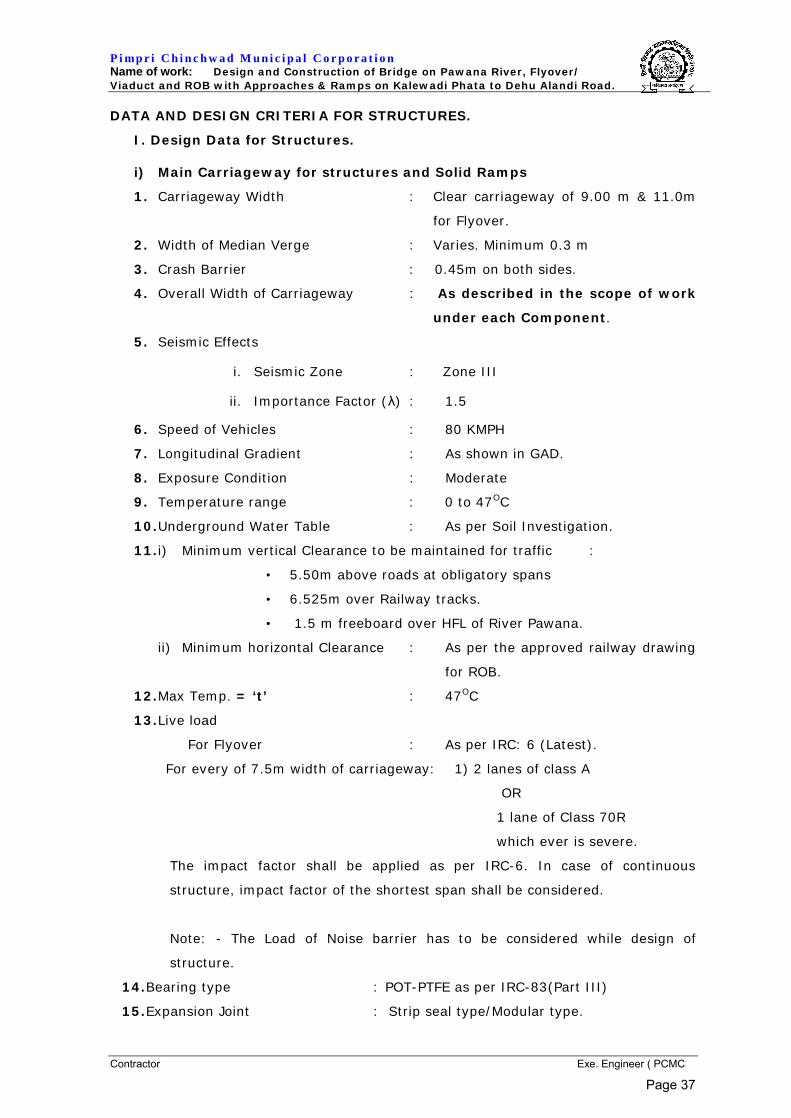
P i mp r i C h i n c h w a d M u n i c i p a l C o r p o r a t i o n Name of work: Design and Construction of Bridge on Pawana River, Flyover/ Viaduct and ROB with Approaches & Ramps on Kalewadi Phata to Dehu Alandi Road.
Contractor Exe. Engineer ( PCMC
DATA AND DESIGN CRITERIA FOR STRUCTURES.
I. Design Data for Structures.
i) Main Carriageway for structures and Solid Ramps
1. Carriageway Width : Clear carriageway of 9.00 m & 11.0m
for Flyover.
2. Width of Median Verge : Varies. Minimum 0.3 m
3. Crash Barrier : 0.45m on both sides.
4. Overall Width of Carriageway : As described in the scope of work
under each Component.
5. Seismic Effects
i. Seismic Zone : Zone III
ii. Importance Factor (λ) : 1.5
6. Speed of Vehicles : 80 KMPH
7. Longitudinal Gradient : As shown in GAD.
8. Exposure Condition : Moderate
9. Temperature range : 0 to 47OC
10. Underground Water Table : As per Soil Investigation.
11. i) Minimum vertical Clearance to be maintained for traffic :
• 5.50m above roads at obligatory spans
• 6.525m over Railway tracks.
• 1.5 m freeboard over HFL of River Pawana.
ii) Minimum horizontal Clearance : As per the approved railway drawing
for ROB.
12. Max Temp. = ‘t’ : 47OC
13. Live load
For Flyover : As per IRC: 6 (Latest).
For every of 7.5m width of carriageway: 1) 2 lanes of class A
OR
1 lane of Class 70R
which ever is severe.
The impact factor shall be applied as per IRC-6. In case of continuous
structure, impact factor of the shortest span shall be considered.
Note: - The Load of Noise barrier has to be considered while design of
structure.
14. Bearing type : POT-PTFE as per IRC-83(Part III)
15. Expansion Joint : Strip seal type/Modular type.
Page 37
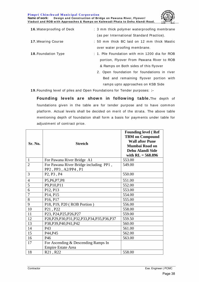
P i mp r i C h i n c h w a d M u n i c i p a l C o r p o r a t i o n Name of work: Design and Construction of Bridge on Pawana River, Flyover/ Viaduct and ROB with Approaches & Ramps on Kalewadi Phata to Dehu Alandi Road.
Contractor Exe. Engineer ( PCMC
16. Waterproofing of Deck : 3 mm thick polymer waterproofing membrane
(as per International Standard Practice).
17. Wearing Course : 50 mm thick BC laid on 12 mm thick Mastic
over water proofing membrane.
18. Foundation Type : 1. Pile Foundation with min 1200 dia for ROB
portion, Flyover From Pawana River to ROB
& Ramps on Both sides of this flyover
2. Open foundation for foundations in river
Bed and remaining flyover portion with
ramps upto approaches on KSB Side
19. Founding level of piles and Open Foundations for Tender purposes: :-
Founding levels are shown in following table.The depth of
foundations given in the table are for tender purpose and to have common
platform. Actual levels shall be decided on merit of the strata. The above table
mentioning depth of foundation shall form a basis for payments under table for
adjustment of contract price.
Sr. No. Stretch
Founding level ( Ref TBM on Compound
Wall after Pune Mumbai Road on Dehu Alandi Side with RL = 568.896
1 For Pawana River Bridge A1 553.00 2 For Pawana River Bridge including PP1 ,
PP2 , PP3 , A2/PP4 , P1 549.00
3 P2, P3 , P4 550.00 4 P5,P6,P7,P8 551.00 5 P9,P10,P11 552.00 6 P12, P13 553.00 7 P14, P15 554.00 8 P16, P17 555.00 9 P18, P19, P20 ( ROB Portion ) 556.00 10 P21 , P22 558.00 11 P23, P24,P25,P26,P27 559.00 12 P28,P29,P30,P31,P32,P33,P34,P35,P36,P37 559.50 13 P38,P39,P40,P41,P42 560.00 14 P43 561.00 15 P44,P45 562.00 16 P46 563.00 17 For Ascending & Descending Ramps In
Empire Estate Area
18 R21 , R22 558.00
Page 38
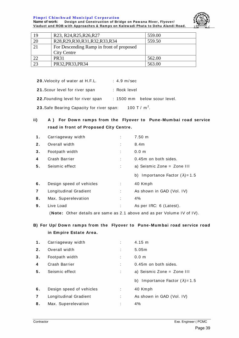
P i mp r i C h i n c h w a d M u n i c i p a l C o r p o r a t i o n Name of work: Design and Construction of Bridge on Pawana River, Flyover/ Viaduct and ROB with Approaches & Ramps on Kalewadi Phata to Dehu Alandi Road.
Contractor Exe. Engineer ( PCMC
19 R23, R24,R25,R26,R27 559.00 20 R28,R29,R30,R31,R32,R33,R34 559.50 21 For Descending Ramp in front of proposed
City Centre
22 PR31 562.00 23 PR32,PR33,PR34 563.00
20. Velocity of water at H.F.L. : 4.9 m/sec
21. Scour level for river span : Rock level
2222.. Founding level for river span : 1500 mm below scour level.
23. Safe Bearing Capacity for river span: 100 T / m2.
ii) A ) For Down ramps from the Flyover to Pune-Mumbai road service
road in front of Proposed City Centre.
1. Carriageway width : 7.50 m
2. Overall width : 8.4m
3. Footpath width : 0.0 m
4 Crash Barrier : 0.45m on both sides.
5. Seismic effect : a) Seismic Zone = Zone III
b) Importance Factor (λ)=1.5
6. Design speed of vehicles : 40 Kmph
7 Longitudinal Gradient : As shown in GAD (Vol. IV)
8. Max. Superelevation : 4%
9. Live Load : As per IRC: 6 (Latest).
(Note: Other details are same as 2.1 above and as per Volume IV of IV).
B) For Up/Down ramps from the Flyover to Pune-Mumbai road service road
in Empire Estate Area.
1. Carriageway width : 4.15 m
2. Overall width : 5.05m
3. Footpath width : 0.0 m
4 Crash Barrier : 0.45m on both sides.
5. Seismic effect : a) Seismic Zone = Zone III
b) Importance Factor (λ)=1.5
6. Design speed of vehicles : 40 Kmph
7 Longitudinal Gradient : As shown in GAD (Vol. IV)
8. Max. Superelevation : 4%
Page 39

P i mp r i C h i n c h w a d M u n i c i p a l C o r p o r a t i o n Name of work: Design and Construction of Bridge on Pawana River, Flyover/ Viaduct and ROB with Approaches & Ramps on Kalewadi Phata to Dehu Alandi Road.
Contractor Exe. Engineer ( PCMC
9. Live Load : As per IRC: 6 (Latest).
(Note: Other details are same as 2.1 above and as per Volume IV of IV).
iii) Provision of Ascending/Descending Unit for Pedestrians.
1. 4 units comprising of the following:
a) 1m wide (Min. clear width) electrically operated Escalator for ascending of
“Hyundai make W-BT 35 degree” type escalator or similar of Schindler or
OTIS brands or equivalent with FRP canopy covering the entire escalator.
b) 1m wide (Min. clear width) electrically operated Escalator for descending
of “Hyundai make W-BT 35 degree” type escalator or similar of Schindler or
OTIS brands or equivalent with FRP canopy covering the entire escalator.
c) One Lift of 15 person capacity for physically handicapped people of “OTIS”
or other equivalent brand makes.
d) RCC staircase of 3.00m clear width with canopy covering.
1. Three Units of doglegged staircase having 2m clear width.
2. Locations : As shown in GAD.
3. Width of flight : as above
4. Height of Riser : 150mm (Max.)
5. Width of Tread : 300mm (Min.)
6. Shade/ Canopy : Poly carbonate sheeting with MS
frame work for covering from all sides of the Staircase arrangement.
II. DESIGN CRITERIA FOR STRUCTURES
1. GENERAL:
The detailed highway and structural design for the work mentioned in the scope
of work is to be done by the bidder. The bidder shall quote on his own design
for span arrangement proposed in GAD tender drawing. It shall generally
satisfy the following requirements: -
(i) It shall ensure soundness of the structure, its durability and
architectural beauty as a whole in harmony with the surroundings.
(ii) It shall ensure speedy construction and lead to appreciable economy.
(iii) It shall be accompanied by preliminary but fairly detailed dimensioned
drawings and detailed description of work and specification of materials
and items. If called upon, bidder shall furnish any additional information
necessary for appreciation and comparison with alternative proposals
received from other bidders.
Page 40
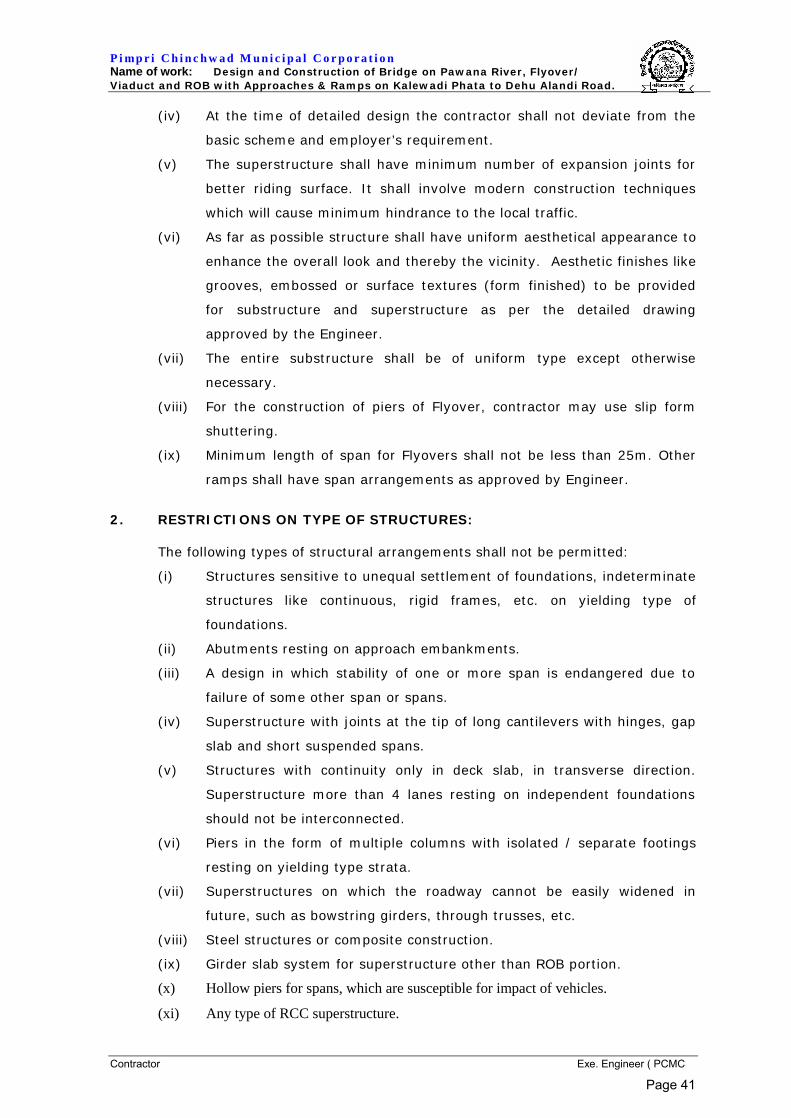
P i mp r i C h i n c h w a d M u n i c i p a l C o r p o r a t i o n Name of work: Design and Construction of Bridge on Pawana River, Flyover/ Viaduct and ROB with Approaches & Ramps on Kalewadi Phata to Dehu Alandi Road.
Contractor Exe. Engineer ( PCMC
(iv) At the time of detailed design the contractor shall not deviate from the
basic scheme and employer’s requirement.
(v) The superstructure shall have minimum number of expansion joints for
better riding surface. It shall involve modern construction techniques
which will cause minimum hindrance to the local traffic.
(vi) As far as possible structure shall have uniform aesthetical appearance to
enhance the overall look and thereby the vicinity. Aesthetic finishes like
grooves, embossed or surface textures (form finished) to be provided
for substructure and superstructure as per the detailed drawing
approved by the Engineer.
(vii) The entire substructure shall be of uniform type except otherwise
necessary.
(viii) For the construction of piers of Flyover, contractor may use slip form
shuttering.
(ix) Minimum length of span for Flyovers shall not be less than 25m. Other
ramps shall have span arrangements as approved by Engineer.
2. RESTRICTIONS ON TYPE OF STRUCTURES:
The following types of structural arrangements shall not be permitted:
(i) Structures sensitive to unequal settlement of foundations, indeterminate
structures like continuous, rigid frames, etc. on yielding type of
foundations.
(ii) Abutments resting on approach embankments.
(iii) A design in which stability of one or more span is endangered due to
failure of some other span or spans.
(iv) Superstructure with joints at the tip of long cantilevers with hinges, gap
slab and short suspended spans.
(v) Structures with continuity only in deck slab, in transverse direction.
Superstructure more than 4 lanes resting on independent foundations
should not be interconnected.
(vi) Piers in the form of multiple columns with isolated / separate footings
resting on yielding type strata.
(vii) Superstructures on which the roadway cannot be easily widened in
future, such as bowstring girders, through trusses, etc.
(viii) Steel structures or composite construction.
(ix) Girder slab system for superstructure other than ROB portion.
(x) Hollow piers for spans, which are susceptible for impact of vehicles.
(xi) Any type of RCC superstructure.
Page 41

P i mp r i C h i n c h w a d M u n i c i p a l C o r p o r a t i o n Name of work: Design and Construction of Bridge on Pawana River, Flyover/ Viaduct and ROB with Approaches & Ramps on Kalewadi Phata to Dehu Alandi Road.
Contractor Exe. Engineer ( PCMC
3. SPECIFICATIONS FOR DESIGN AND CODES TO BE FOLLOWED:
The design of structural components shall conform to the criteria laid down in
the latest editions of the following codes of Practice and Standard specifications
published upto 3 months prior to last date of issue of tender form and subject
to the departures stipulated in these tender documents.
(A) I.R.C. Standard Specifications and Codes of Practice for Road Bridges. :
Section - I I.R.C. 5 General features of design.
Section -II I.R.C. 6 Loads and stresses.
Section -III I.R.C.21 Cement concrete plain and
Reinforced (Second Revision).
Section - V I.R.C.24 Steel road bridges for permissible stress
only.
(Other provisions as per AASHTO Code)
Section -VI I.R.C.22 Composite construction for road bridges (for
permissible stresses only) (Other provisions
as per B.S.5400 part 3, 5, 6).
Section -VII I.R.C.78 Foundation and substructure.
Section -IX I.R.C.83 (Part-I) Metallic Bearings.
Section -IX I.R.C.83 (Part-III) POT, POT CUM PTFE PIN AND
METALLIC GUIDE BEARINGS.
I.R.C: 18 Design criteria for prestressed concrete
Road Bridges (Post tensioned concrete).
I.R.C: SP 64 Guidelines for design of voided slabs
I.R.C: SP 65 Guidelines for design of segmental bridges.
I.R.C: SP 66 Guidelines for design of continuous bridges.
I.R.C: SP 70 Guidelines for the use of High Performance
Concrete bridges.
I.R.C: SP 71 Guidelines for design and construction of
precast pre-tensioned girders for bridges.
IS 2911 Code of practice for design and construction
of pile foundations.
IS 13920 Ductile detailing of reinforced concrete
structures subjected to seismic forces -
Code of practice.
IS 1893 (Part I) Criteria for earthquake resistant Design of
structures.
MORT&H specifications for Road and Bridge Work-2001.
Page 42
P i mp r i C h i n c h w a d M u n i c i p a l C o r p o r a t i o n Name of work: Design and Construction of Bridge on Pawana River, Flyover/ Viaduct and ROB with Approaches & Ramps on Kalewadi Phata to Dehu Alandi Road.
Contractor Exe. Engineer ( PCMC
Provision of seismic details as per India Highway Publication.
For structure within Railway area provision as per following
Indian Railway Standard Code shall be made.
a) Code of Practice for Plain, Reinforced and Pre-stressed
Concrete for general Bridge Construction (Concrete Bridge
Code) Second Revision – 1997.
b) Code of Practice for the design of sub-structures and
foundations for Bridges (Bridge sub-structures foundation
code).
c) Specification for RCC/ PSC for the construction,
Rehabilitation of Concrete Bridges and structures on
Central Railway (open line) issued on 1/12/2000.
(B) Any I.R.C. standard specifications and codes of practice or criteria for
road bridges other than "A" above, but published 3 months prior to last
date of issue of tender form.
(C) For any item not covered by A & B above, specification for Road and
Bridge works published by I.R.C. for Ministry of Road Transport and
Highways, Government of India.
(D) For items not covered by any of the A, B & C above relevant provisions
of IS codes of practice.
(E) For any item not covered by A, B, C & D above, the relevant provisions
from B.S. Codes of Practice.
(F) For items not covered by any of the above Standards and Specifications,
sound Engineering practice and provisions in the Departmental design
and provisions of relevant Codes of other nation shall be referred. In this
regard decision of the Engineer’s Representative shall be final and
binding.
4. OBLIGATORY PROVISIONS
4.1 Alignment and location
Alignment and location of the Flyover Structure and ROB shall be as
shown in the Departmental drawings. The Co-ordinates and levels shall
be approved by The Engineer.
Page 43
P i mp r i C h i n c h w a d M u n i c i p a l C o r p o r a t i o n Name of work: Design and Construction of Bridge on Pawana River, Flyover/ Viaduct and ROB with Approaches & Ramps on Kalewadi Phata to Dehu Alandi Road.
Contractor Exe. Engineer ( PCMC
4.2 The Length of main Flyover Structure and ROB:-
The length of the Flyover shall satisfy the following criteria.
(a) The centre line of the various structures as shown on the GADs
should not be changed, except under unavoidable circumstances
with approval from the Employer.
(b) Maximum height of embankment at abutment location shall not
be more than 4.5m and clear height below the soffit shall not be
less than 1.5m.
(c) Longitudinal gradient shall not be steeper than those shown in
departmental drawings. The Vertical and Horizontal curves should
be smooth with radius not less than shown in GAD.
(d) Restrictions on terminal points if specially mentioned in
departmental drawings.
(e) Any other criteria shown on the departmental drawings /
supplementary data.
(f) Overall length of River Bridge/ Flyover/ ROB proper and
structural viaduct shall not be less than the length shown in
departmental drawings.
(g) In case of Flyover, the horizontal and vertical clearances and pier
locations shown for the obligatory spans shall be as per
departmental drawings.
(h) Locations of obligatory spans shall be as shown in the
Departmental Drawings. They may be changed slightly during
execution as per site requirements with approval from the
Employer.
(i) In case of ROB, the minimum Vertical and Horizontal Clearances
under the Railway Bridge Portion shall not be less than those
shown in departmental drawing i.e. approved GAD from
Railways.
(k) It is obligatory to locate pier No P42 , P43 (Over NH-4 Road), in
the Landsacape Portion only and the width of the pier shall not
exceed 2m.
(l) It is obligatory to locate pier No P3 , P4 (Over 18.00 D.P.Road),
as shown in the GAD.
Page 44
P i mp r i C h i n c h w a d M u n i c i p a l C o r p o r a t i o n Name of work: Design and Construction of Bridge on Pawana River, Flyover/ Viaduct and ROB with Approaches & Ramps on Kalewadi Phata to Dehu Alandi Road.
Contractor Exe. Engineer ( PCMC
(m) It is obligatory to locate pier No P10 , P11 (Over Existing Pimpri-
Chinchwad Link Road), as shown in the GAD.
(n) It is obligatory to locate pier No P41 , P44 (Over Existing Pune-
Mumbai Road), as shown in the GAD.
(o) Size and shape of pier shall be kept uniform for all piers of same
carriageway width.
(P) It is obligatory to construct Portal Frames Substructure for pier
No P5, P6, P7, P8, P9 & P14, P15, P16 on Left side of
Flyover/Viaduct as shown in the GAD.
4.3 Road Level on the Flyover and Roadway Particulars:
(a) Roadway particulars and carriageway widths shall be as per
relevant Departmental drawing.
(b) The vertical geometry of the finished surface of deck slab and
wearing course shall be in the form of a smooth curve where
change in gradient occurs. The design of curves shall be got
approved from the Engineer. Super-elevation, camber & widening
on curves shall be suitably considered. The design of curves shall
be such that rate of change of vertical curvature (‘K’ value) shall
not be less than those shown in tender drawing. The design
speed on curve shall be as stipulated in Design Data.
4.4 The span arrangement for complete project, horizontal and vertical
geometry shall remain unchanged. Under unavoidable circumstances
minor modifications can be permitted after approval by the Engineer in-
charge.
5. BORING DATA AND SOIL AT SITE.
5.1 The Soil Investigation report is attached herewith in Volume III of the
Tender Document as “Annexure A to Volume III”.
5.2 The contractor shall have to take borings by double tube boring machine
for each carriageway at the final location of each pier and abutment
prior to the commencement of the work to ascertain the rock
levels/quality at the location of the foundations and this shall form part
of the contract and no payments will be made by the Department for
boring, soil sampling and testing etc.
Page 45
P i mp r i C h i n c h w a d M u n i c i p a l C o r p o r a t i o n Name of work: Design and Construction of Bridge on Pawana River, Flyover/ Viaduct and ROB with Approaches & Ramps on Kalewadi Phata to Dehu Alandi Road.
Contractor Exe. Engineer ( PCMC
(a) During execution of the work, the samples from the bore taken at each
foundation shall be tested for relevant tests and analyzed in the
laboratory approved by the department for establishing design
parameters. Tests such as standard penetration test, compression and
shear test on undisturbed soil samples, etc., shall be carried out in
conformity with the specifications. The Contractor shall submit the entire
data to the Engineer along with his own/laboratory recommendations
and obtain approval to the design-parameters. Necessary interpretation
of the result of tests shall be furnished to the Engineer for scrutiny of
design of foundations.
(b) The cost of these test and interpretation of the test results shall be
included in the tendered amount. No payment will be made separately
for the testing of soil or rock.
(c) The S.B.C. at the foundation level shall be verified during construction
so as to ensure that the stresses imposed on the foundation strata are
within permissible limit. However, if some additional borings are
required by the department such requirement shall be ordered in writing
and shall be deemed to be an additional work. The Contractor shall
quote the rate for such boring, soil sampling and testing, separately
along with his tender. The taking out of samples and carrying out
required tests shall be in conformity with the departmental
specifications. The Contractor shall then submit the entire data to the
Department along with his own/laboratory recommendation and obtain
approval to the design parameters.
6. FOUNDATIONS:
6.1 Piers/Abutments:
6.1.1 For bidding and for the purpose of tender, general foundation levels
proposed for the piers & abutments shall not be higher than those
proposed in the Employers design. Where pier positions differ from the
departmental design, the levels shall be interpolated for the purpose of
this clause.
The Founding Levels to be considered as a benchmark in deciding the
+/- variations (Pursuant to the Schedule of Variations of Volume-I) shall
be as per 19 of Data and Design criteria for structures.
Page 46
P i mp r i C h i n c h w a d M u n i c i p a l C o r p o r a t i o n Name of work: Design and Construction of Bridge on Pawana River, Flyover/ Viaduct and ROB with Approaches & Ramps on Kalewadi Phata to Dehu Alandi Road.
Contractor Exe. Engineer ( PCMC
6.1.2 Detailed design shall be carried out only with pile/open
foundation for abutments and piers as shown in GAD (.
6.1.3 The maximum base pressure under worst combination of loads &
stresses condition for open foundation shall not exceed 100 T/m2. The
allowable stresses shall be as per codal provisions.
6.1.4 Buoyancy to be considered shall be 100% for open as well as pile
foundation.
6.1.5 Abutment structure shall be fully retaining Reinforced Concrete
structure. No passive pressure shall be considered for the design of
abutment.
6.1.6 While checking the stresses at the base of foundations it shall be
ensured that under the worst combination of forces there is no tension.
6.2 Ramp / Retaining walls
6.2.1 The solid ramp portion of the Flyover shall be a Reinforced Soil retaining
structure with decorative facia. Open foundation for retaining structure
is acceptable. The foundation shall be taken minimum 1.5m below road
level with SBC of 20 T/m2.
6.2.2 For foundation of Retaining structure if design requires increasing SBC at
foundation level by any soil stabilization method, the cost of this
stabilization shall be borne by the Contractor.
6.2.3 Kerb stones shall be provided parallel to the retaining wall to protect it
from damages and to channelize the traffic running on side roads. The
gap between the kerb & Retaining wall shall be filled up with sand and
covered with interlocking blocks atleast 500 mm on either side.
6.2.4 Reinforced Soil Retaining Wall (RE Wall ) for Pawana river Bridge, Facia
Panel shall be 600 mm H.F.L behind the abutment and it shall be based
on concrete wall M300 with minimum thickness 750 mm.
6.3 Pile foundations
6.3.1 The pile foundation shall be designed considering various load
combination forces and permissible stresses as per the latest edition of
I.R.C.78. The piling shall be done by hydraulically operated rotary
drilling machine only.
Page 47

P i mp r i C h i n c h w a d M u n i c i p a l C o r p o r a t i o n Name of work: Design and Construction of Bridge on Pawana River, Flyover/ Viaduct and ROB with Approaches & Ramps on Kalewadi Phata to Dehu Alandi Road.
Contractor Exe. Engineer ( PCMC
a. 8 mm thick M.S. liner with end stiffeners of 300 mm height and of
equal thickness at the bottom shall be provided to the piles from the
bottom of pile cap up to rock level with anticorrosive treatment
specified under Clause 2.22 for the piles in the ROB portion at pier
locations PL26, PL27, PR28 & PR29 (Refer Dwg. GAD for Railway
span of vol IV). For piles at other location, temporary liner may be
provided wherever it is necessary.
b. Shift and tilt of pile shall be considered as per IRC: 78 – 2000.
6.3.2 The following criteria shall be considered for deciding the length of
embedment.
1. The minimum embedment of piles in hard rock (RMR value more
than 70 as per IS: 12070) shall not be less than 1.25 times diameter
of pile. The pile capacity in rock shall be calculated as per IRC: 78
(latest edition).
2. Safe Bearing Capacity of rock shall be worked out on the basis of
RMR value. In no case the capacity of pile shall exceed 500 Tons
under normal condition with the embedment mentioned above.
Minimum embedment is required to be provided despite this
limitation on pile capacity..
3. The piles shall be designed as fixed end bearing. Fixity shall be
considered at the top of rock where the socketing begins and at the
center of pilecap. Side friction from G.L. up to embedment level shall
not be considered for design. Support from surrounding strata shall
not be considered for design of piles.
6.3.3 The pile capacity shall be confirmed by pile load test as per IS-2911
(Part IV).
1. The vertical and horizontal design capacity assumed for the piles
shall be verified by the initial load testing of test piles in non-working
areas, in the vicinity of the bridge site. These piles shall be tested for
2.5 times the design load. Initial test shall be carried out on one pile
per dia. for viaduct portion and one pile for ROB portion. Additional
one pile per dia., which is actually going to be used for piers and
abutments, shall be tested for 1.5 times the design load. These tests
and the routine tests shall be as per I.R.C. 78 (Latest edition). The
dynamic load test and the pile integrity test may be permitted
Page 48
P i mp r i C h i n c h w a d M u n i c i p a l C o r p o r a t i o n Name of work: Design and Construction of Bridge on Pawana River, Flyover/ Viaduct and ROB with Approaches & Ramps on Kalewadi Phata to Dehu Alandi Road.
Contractor Exe. Engineer ( PCMC
subject to verification of the results with static load test performed
on the same pile.
2. The lateral Load carrying capacity of pile shall be assessed by
carrying out lateral load test on a single pile for a deflection of 5 mm
at top.
3. Side friction (Skin Friction) from G.L. upto embedment level shall not
be considered during design.
4. The piles shall be designed as end bearing considering fixity as
mentioned above. There shall be no tension at the base of pile under
any load combination.
5. The minimum dia. of piles shall be 1200mm.
6. Annular piles filled or unfilled shall not be accepted.
7. Design with single row of piles shall not be accepted.
8. Use of High performance concrete for piles is not permitted (M60 and
above).
9. NDT Tests at regular intervals as directed by the Engineer for at
least 10% of total number of piles shall have to be carried out by the
contractor with no cost to the employer.
10. The cost of all above tests shall be borne by the contractor and no
extra payment will be made to the contractor.
11. Only bored cast in situ piles shall be accepted.
12. For piles within ROB, Railway area, minimum dia. of pile, MS liner to
pile, provision of anticorrosive treatment to reinforcement, method
of construction of pile etc. shall be as per IRC Code and as per
drawing approved by Railway authorities.
7. SUBSTRUCTURE
For continuous spans pier, with fixed bearing shall be designed to take all the
horizontal forces.
7.1 Minimum Dimension of any element of substructure shall not be less
than 300 mm.
7.2 Dead man anchors or friction slabs shall not be accepted behind
abutment for relieving moments.
7.3 Scope for accessibility for inspection and arrangement for lifting of the
superstructure for future replacement of bearings shall be provided for
in the design of substructure. The positions of jacks shall be distinctly
marked on the drawing and on pier / pier cap.
Page 49
P i mp r i C h i n c h w a d M u n i c i p a l C o r p o r a t i o n Name of work: Design and Construction of Bridge on Pawana River, Flyover/ Viaduct and ROB with Approaches & Ramps on Kalewadi Phata to Dehu Alandi Road.
Contractor Exe. Engineer ( PCMC
7.4 The height of pedestals plus bearing shall be min. 150 and maximum
500 mm.
7.5 Slender piers shall be checked for deflection under horizontal and
eccentric forces and secondary forces if any. Pier, bearings and
expansion joints shall be suitably designed.
7.6 One span dislodged condition shall be considered as erection condition
(load combination VI, VII of IRC-6) for the purpose of design.
7.7 Earth retaining structure shall be designed for the earth pressure
calculated as per any theory permitted by the IRC Codes.
7.8 Special aesthetic finishes like grooves etc. shall be given to the
structures to the satisfaction of the Engineer. Aesthetic finishes shall not
form the part of structural requirement of any member.
7.9 All the piers in the central verge (median) shall be designed for a vehicle
collision load as per IRC provisions.
8. SUPERSTRUCTURE
General:
(a) Only PSC Box / PSC voided slab -type superstructure is allowed in all
locations except in ROB portion if railway authority does not allow for
box Type Superstructure. Alternatively pre-cast ’I’ girder section may be
provided for obligatory span of ROB if insisted by railways as per their
requirements.
Stage construction of deck slab is not allowed. Deck slab shall be
designed for 40t bogie load (class 70R load) and wheeled vehicle of
Class AA vehicle in addition to loading mentioned in Design Data.
Minimum thickness of deck slab, soffit slab, webs shall be as per sketch
given in Annexure-1 and satisfy all the provisions of IRC-18 2000.
(b) In case of voided slab minimum thickness of concrete cover to the void
shall be 200 mm above the void and 250 mm below the void. The
arrangement for draining out water from voids shall be made. Solid
slabs are not allowed
(c) Superstructures designed for continuity only under live loads shall be
permitted.
Page 50
P i mp r i C h i n c h w a d M u n i c i p a l C o r p o r a t i o n Name of work: Design and Construction of Bridge on Pawana River, Flyover/ Viaduct and ROB with Approaches & Ramps on Kalewadi Phata to Dehu Alandi Road.
Contractor Exe. Engineer ( PCMC
(d) Superstructure shall be designed for 10 mm differential lifting at bearing
location. This shall be considered as an erection condition.
(e) It shall be obligatory to carry out design based on longitudinal and
transverse analysis
(f) The superstructure shall have minimum expansion joints to enhance
riding quality. The depth of superstructure shall be such that span to
depth ratio is not less than 15 for box girder and 12 for I girder
including deck slab.
(g) Special aesthetic finishes like grooves etc. shall be given to the sides
and soffit of superstructure to the satisfaction of the Engineer. Aesthetic
finishes shall not form the part of structural requirement.
9. DESIGN LOADS:
9.1 Live Loads:
9.1.1 The bridge shall be designed to carry combination of I.R.C loadings, as
per clause 207.4 (IRC: 6-2000) whichever produces worst effect.
While checking for one span off condition, live load of IRC Class-A one
lane per two lanes without impact shall be taken into account and this
shall not be considered in conjunction with seismic / wind force. Braking
force shall not be considered.
9.1.2 The design shall cater for renewal / overlaying of wearing coat load of
110 Kg/m2.
9.1.3 Loads from services facilities viz. electrical cable, telephone cable at 100
Kg/m or actual loads whichever is higher on either side of carriageway.
9.1.4 Loads from other utilities and pedestrian loading shall be as per “Design
Data”.
9.1.5 For Railway Portion - As per IRC:6 - 2000 or as approved by Railway
Authority whichever produces worst effect.
9.2 Construction Loads
The structure shall be designed for the load coming from the launching
girder, beam and winch system, segment delivery trailer etc. Impact of
such loads shall be considered not less than 10% total load.
Page 51
P i mp r i C h i n c h w a d M u n i c i p a l C o r p o r a t i o n Name of work: Design and Construction of Bridge on Pawana River, Flyover/ Viaduct and ROB with Approaches & Ramps on Kalewadi Phata to Dehu Alandi Road.
Contractor Exe. Engineer ( PCMC
9.3 Wind Forces:-
9.3.1 Wind forces shall be considered in the following two ways. The
design shall be governed by the one producing the worst effect.
(i) Full wind force at right angles to the superstructure.
(ii) 65 % of wind force as calculated in (i) above acting
perpendicular to the superstructure and 35 % acting in
traffic direction.
9.4 Temperature-Range:-
(i) For design of structure to account for temperature in formula
dL = alpha x L x t, the value of "t" shall be 50 degrees centigrade
i.e., ± 25 for extreme atmospheric exposure condition.
Note: - The temperatures variation shall be accounted for in
design of structures as per design data.
Alpha is the Coefficient of Expansion or Contraction and L
is the length of the member and dL is the expansion or
contraction due to a variation of temperature in
appropriate units.
(ii) The superstructure shall also be designed for effects of
distribution of temperature across the deck depth as per IRC: 6-
2000. For calculation of thermal forces effect of 'E' value of
concrete should be taken as 50% of the instantaneous value so
as to account for effects of creep on thermal strains.
9.5 Soil Properties:
In absence of actual field data the properties of back fill, shall be
considered for design purpose as below:
i) Dry Density of Soil - 1.8 T/Cum.
ii) Saturated Density - 2.0 T/Cum.
iii) Ø = 30 Degree, δ = 20O
iv) C = 0
9.6 Seismic Forces:-
For the calculation of fundamental period, as per appendix 2
(amendment No. 6) of IRC: 6 -2000, the length shall be considered
from top of the pier cap to top of pilecap/footing.
Page 52
P i mp r i C h i n c h w a d M u n i c i p a l C o r p o r a t i o n Name of work: Design and Construction of Bridge on Pawana River, Flyover/ Viaduct and ROB with Approaches & Ramps on Kalewadi Phata to Dehu Alandi Road.
Contractor Exe. Engineer ( PCMC
The seismic coefficient so calculated shall be applied for foundation and
substructure design.
10. PERMISSIBLE STRESSES:-
10.1 Allowable stresses for plain and reinforced concrete shall be as per IRC-
21 and for prestressed concrete (post tensioned) as per IRC-18.
10.2 The permissible shear stresses shall be as given in IRC-21 & IRC-18.
11. DURABILITY
11.1 Grade of Concrete
11.1.1 Minimum grade of concrete for Foundation shall be M30.
11.1.2 Minimum grade of concrete for substructure shall be M30.
11.1.3 Minimum grade of concrete for superstructure shall be M45.
11.1.4 Minimum grade of concrete for pile foundation shall be M35.
11.2 Minimum Cement Content
11.2.1 For both plain and reinforced concrete, the value given below
regarding minimum cement content and maximum water-
cement ratio shall be as per Clause 302.6 Table No. 5(A) of
IRC: 21-2000
11.2.2 High strength ordinary Portland cement conforming to
I.S.12269 will also be permitted.
11.3 The minimum nominal dia. of reinforcement and clear cover shall
be as follows
(Only Fe-500 TMT CRS steel shall be used).
11.3.1 The minimum nominal dia. of reinforcement shall be 10 mm.
11.3.2 Minimum clear cover to reinforcement for all grades of con-
crete shall be as per Clause 304.3 IRC: 21-2000.
11.3.3 The cover shall be measured from the inner face of the
groove for substructure and superstructure.
11.4 The H.T.S. strands to be used for P.S.C. structures shall be Stress
Relieved Low Relaxation Steel conforming to Class-II of latest IS:
14268.
Page 53
P i mp r i C h i n c h w a d M u n i c i p a l C o r p o r a t i o n Name of work: Design and Construction of Bridge on Pawana River, Flyover/ Viaduct and ROB with Approaches & Ramps on Kalewadi Phata to Dehu Alandi Road.
Contractor Exe. Engineer ( PCMC
11.5 Anticorrosive protective paints to foundation, substructure and
superstructure shall be as per Clause No. 20.
12. PSC BOX GIRDERS
12.1 For proportioning of the box girder, the sketch given in Annexure-1 of
this volume shall be adopted. Overhangs shall not be more than those
shown in the drawing in Annexure-1.
The entire box shall be a single unit without any construction joint in
longitudinal direction.
12.2 Minimum thickness of intermediate diaphragm provided shall be 300
mm and that of end diaphragm shall be 500 mm.
12.3 Two manholes shall be kept in soffit of every span with arrangement for
access inside the box.
12.4 The following method of analyzing and designing box girder is
acceptable.
(i) Calculate the main girder moments, shear forces and torsional
moments as for a single beam.
(ii) Also add to above, the forces due to the restraint of warping
torsion at the ends.
(iii) In addition, calculate the bending moments in the roadway slab
considering the slab, the web and soffit slab as a closed frame.
(iv) Reinforcement in the slabs and webs due to the transverse
moments must be provided in addition to the steel, which is re-
quired for shear or torsion in the box as a main girder.
(v) Distortion of box girder due to transverse moment should be
considered in the design.
(vi) In the absence of rigorous analysis (a) for the torsional moment
(b) for forces due to restraints of warping torsion at ends the
design live load moments and shear force in the longitudinal
direction shall be increased by 20% and transverse reinforcement
steel be increased by 5%.
(vii) While designing the various components like bearings, pedestals
etc., the maximum and minimum reaction as per detailed
transverse analysis shall be considered.
Page 54
P i mp r i C h i n c h w a d M u n i c i p a l C o r p o r a t i o n Name of work: Design and Construction of Bridge on Pawana River, Flyover/ Viaduct and ROB with Approaches & Ramps on Kalewadi Phata to Dehu Alandi Road.
Contractor Exe. Engineer ( PCMC
13. PRESTRESSED CONCRETE
(a) Permissible stress in concrete during service shall be as per Clause 7.2
of IRC: 18-2000.
(b) All prestressed members shall have spare cables laid to the profiles
approved by the Department. The number of spare cables shall be 5%
of the cables required as per design, subject to a minimum of one cable
per girder/web. These cables shall be permitted to be removed fully or
partly after the final stage of prestressing, if they are not required holes
shall be grouted. In case of saline atmosphere these cable holes shall
not be grouted but only ends shall be closed properly.
(c) The provision for imparting 20% of design prestress at a future date
shall be made in the deck and suitable anchorages; bulkheads
diaphragms etc. shall be constructed for the purpose. Arrangement for
external prestressing shall be got approved from the Engineer.
(d) Sheathing for post - tensioned superstructure shall be corrugated HDPE
type as per IRC: 18-2000.
(e) The ends of prestressing anchorages in case of post-tensioning shall be
protected against corrosion.
14. PRECAST SEGMENTAL CONSTRUCTION
14.1 Precast segmental construction if adopted shall be designed as per
Clause 7.2.3 of IRC:18-2000 and IRC:SP-65 and Guide specifications
for design and construction of concrete segmental bridges (latest).
14.2 Requirements regarding minimum dimensions shall be as per
Annexure I of this volume. External prestressing within the box with
necessary protection against corrosion shall be allowed.
14.3 For construction with continuous spans the portion over piers, the key
segments and end segments at expansion joints may be cast in situ;
all other segments shall be precast. For simply supported spans all the
segments shall preferably be precast.
14.4 All the segments shall be match-cast. During match-casting necessary
care shall be taken to minimize the effect due to temperature arising
from hydration of concrete of adjacent segment.
14.5 The shear keys at the face of segments shall be as under:
Page 55

P i mp r i C h i n c h w a d M u n i c i p a l C o r p o r a t i o n Name of work: Design and Construction of Bridge on Pawana River, Flyover/ Viaduct and ROB with Approaches & Ramps on Kalewadi Phata to Dehu Alandi Road.
Contractor Exe. Engineer ( PCMC
(a) On each web single key or multiple keys shall be provided.
These keys shall be designed to transmit shear forces.
(b) On the top and bottom slabs keys shall be provided to maintain
alignment and level.
14.6 Formwork shall be robust and the foundations of the casting and
stacking yard shall be designed to safely support all applied loads
without undesirable deformations or settlements.
14.7 In order to achieve smooth profile of prestressing cables and to
prevent entry of cement slurry at the joints of matching segments;
pipe shall be inserted through the cable duct of both the segments
(i.e. matching segment and segment being cast) at the time of
concreting.
14.8 Bond breaking agents shall be used while casting the segments so that
the segments can be easily separated after casting.
14.9 The joints between adjacent segments shall be treated with
appropriate epoxy formulation to facilitate erection and to fill cavities if
any. While applying epoxy, care shall be taken to see that the epoxy
does not block the openings of the cable ducts.
Epoxy shall be applied on the interfaces of both the segments and the
segments shall be subjected to a pressure of minimum 2 Kg/cm2. This
may be achieved either by using temporary pre-stress or by any other
method. Permanent cables shall be introduced in the duct and after
pre-stressing the required number of cables the temporary pressure
can be released.
14.10 The method of erection of segments shall be such that the desired
geometric profile of the bridge deck is obtained. During erection stage
temporary blockade of one lane of traffic may be allowed with the
permission of Employer.
14.11 The segments shall be checked for stresses during handling and
erection.
14.12 Reference may be made to document "Guide to good practice:
Recommendations for segmental construction in pre-stressed con-
crete" published by F.I.P.
Page 56
P i mp r i C h i n c h w a d M u n i c i p a l C o r p o r a t i o n Name of work: Design and Construction of Bridge on Pawana River, Flyover/ Viaduct and ROB with Approaches & Ramps on Kalewadi Phata to Dehu Alandi Road.
Contractor Exe. Engineer ( PCMC
14.13 The launching/erection of all the precast segmental superstructure
segments shall be carried out by over slung method using launching
girders. The decision to adopt under slung method for
launching/erection shall be as per the discretion of the Engineer.
15. BEARINGS BELOW SUPERSTRUCTURE:
(a) POT-PTFE Bearing from MORT&H approved manufacturers in cast steel
shall only be permitted.
(b) The bearings shall be easily accessible for inspection.
(c) Scope for lifting the superstructure for future replacement of bearings
shall be provided for in the design of bearing. The scheme of lifting shall
be indicated on the drawing to be submitted at the time of tendering.
(d) The contact surface of superstructure shall project beyond the edge of
the bearing plate by a minimum distance of 100 mm at any location.
16. EXPANSION JOINTS:
16.1 Only strip seal joints (for horizontal movement upto 80 mm), modular
strip joints (for horizontal movement beyond 80 mm) shall be permitted,
conforming to modified interim specifications for expansion joints.
16.2 The expansion joints should generally be spaced at not less than 80 m.
except in case of unavoidable circumstances.
16.3 Uniform type of expansion joint shall be provided for the entire deck.
16.4 All the expansion joints shall be water tight.
16.5 Expansion joints shall conform to MORT&H specifications and procured
from MORT&H approved manufacturers.
17. RAILINGS, PARAPET, CRASH BARRIERS AND MEDIAN VERGE:
17.1 Anti crash barriers having a typical cross section as shown in Annexure-
2 shall be provided.
17.2 Providing R.C.C. median, sand filling inside median, DWC pipes 4 Nos.,
interlocking blocks, bitumen pad in expansion gap etc. as per tender
drawing.
Page 57
P i mp r i C h i n c h w a d M u n i c i p a l C o r p o r a t i o n Name of work: Design and Construction of Bridge on Pawana River, Flyover/ Viaduct and ROB with Approaches & Ramps on Kalewadi Phata to Dehu Alandi Road.
Contractor Exe. Engineer ( PCMC
18. WATER SPOUTS
Water spouts as per MORT&H Type design No.SD/303 shall be provided.
However, the diameter of pipe shall be 150 mm.
Waterspout shall be 150 mm φ G.I. and connected to runner pipe (HDPE type)
of suitable diameter (Minimum 150 mm) and taken down by down take HDPE
pipes of suitable diameter at approved locations. Arrangement for clean out
plug shall be made.
Collection chamber shall be made and shall be connected to nearest S.W. drain
through 300mm dia. NP4 pipe.
19. WEARING COAT:
A wearing course of 12 mm mastic will be laid on 50 mm Bituminous Concrete
laid on over 3 mm thick waterproofing membrane shall be provided over the
concrete deck. However on approaches a flexible wearing course as shown in
the departmental drawing shall be provided.
20. ANTICORROSIVE PAINT:
Anti-corrosive protective paint as mentioned below and approved by the
Engineer shall be provided. This paint shall be got tested from the approved
laboratory and shall be of approved quality, colour and shade.
The protective coating shall be applied to:
(a) Superstructure and Part of substructure exposed to atmosphere - Anti
carbonation acrylic paint of synthetic enamel in two coats each of
minimum 70 micron shall be provided.
(b) Part of foundation / substructure in contact with earth upto GL or in
contact with water - one coat of primer and two coats of coal tar epoxy.
Total DFT 210.
(d) The superstructure shall be treated with following protective coatings.
(i) Parapets/ Railings / Crash Barriers
Waterproof cement based paint of approved quality and colour in
three coats.
(ii) Deck/Girder/box and inner surface of the Superstructure
Waterproof cement based paint in three coats of approved quality
and colour.
Page 58
P i mp r i C h i n c h w a d M u n i c i p a l C o r p o r a t i o n Name of work: Design and Construction of Bridge on Pawana River, Flyover/ Viaduct and ROB with Approaches & Ramps on Kalewadi Phata to Dehu Alandi Road.
Contractor Exe. Engineer ( PCMC
21. ELECTRICAL WORK / STREET LIGHTING:
The scope of work covers providing and fixing following items as per details given
in tender
1. Junction boxes, pullout boxes.
2. Sleeves, base plate and anchor bolt for fixing electrical poles.
3. Provide 110 mm φ Double Wall Corrugated (DWC) pipe of PE with IS
14930 Part-II mark, one in each crash barrier for entire length of Flyover
and up to nearest junction box.
4. Providing 110 mm φ Double Wall Corrugated (DWC) pipe of PE with IS
14930 Part-II mark 4 Nos. in median (as shown in tender drawing) for
entire length of Flyover and up to nearest junction box.
5. All the material shall be new and conform to latest IS Specification and
shall be procured from approved manufacturer only.
6. Providing and fixing electrical poles along with complete fixtures and
lights of appropriate lux as per IRC Standards through out the length on
Flyover and road below the Flyover.
7. Lighting below the Flyover shall be carried out with appropriate fittings
and illumination not less than 80 lux.
8. The work of landscaping shall be carried out in the all medians, islands,
channelisers and open spaces within the ROW.
The Contractor shall carry out and complete the said work (including labour,
material, appliances, equipment etc.) under this contract in every respect in
conformity with current rules & regulations of local electricity authority, Indian
Standard Institution and with the directions and to the satisfaction of the
Engineer. For more details refer SP- 7 of vol III of tender document.
22. MISCELLANEOUS:
i. Pillars with granite tablets:
Provision of suitable pillars, one at each corner of the bridge, of suitable
architectural design to define the ends of the Flyover with suitable
pedestals to house granite tablets as per details to be got approved by
the Engineer.
ii. Lane markings:
Page 59
P i mp r i C h i n c h w a d M u n i c i p a l C o r p o r a t i o n Name of work: Design and Construction of Bridge on Pawana River, Flyover/ Viaduct and ROB with Approaches & Ramps on Kalewadi Phata to Dehu Alandi Road.
Contractor Exe. Engineer ( PCMC
Provision of necessary lane markings with thermoplastic paint, reflecting
lane studs etc., on the Flyovers, ramps and service roads.
iv. Design and construction of staircases as shown in Departmental Drawing.
v. Providing RCC Road Kerb, Median, Sand filling in median, service ducts,
interlocking blocks over median, wearing coat, bearing, expansion joint
and protective coat for Flyover as per tender.
vi. Resurfacing:
The road surface below Flyover and service road shall be cleaned properly
and resurfaced to bring to original condition before completion of work.
vii. Overhead Gantry / Sign Boards / Signals:
Providing and fixing in position overhead Gantry frame, trustles sign
boards/signals as per approved drawings and specifications.
viii. Architectural treatment:
Providing architectural treatment/ features as per approved drawings and
as suggested by the Architect of Consultants to PCMC during the course of
execution.
ix) Traffic diversion:
Providing and maintaining necessary traffic diversion, barricading of site
during construction such that 7.5 m clear carriage way is available on
both sides at any given point of time. Details of barricading shall be as
per annexure III. The complete area of work shall be cordoned off with
necessary barricading as mentioned herein. There should not be any
hindrance to the traffic. Centering scheme shall be designed on the same
basis as that of barricading.
23. ENVIRONMENT & DURABILITY:
Some of the most important issues in this connection are as under:
i. High tensile steel shall be stored as per stipulated in I.S. codes and duly
protected during storage. It shall be procured properly sealed and
protected from rusting using all possible measures.
ii. Restricting the water cement ratio of concrete and increasing the
workability by the use of carefully selected plasticizers / additives
approved by the Engineer.
Page 60
P i mp r i C h i n c h w a d M u n i c i p a l C o r p o r a t i o n Name of work: Design and Construction of Bridge on Pawana River, Flyover/ Viaduct and ROB with Approaches & Ramps on Kalewadi Phata to Dehu Alandi Road.
Contractor Exe. Engineer ( PCMC
iii. Employment of large pre-stressing unit whose strands can be threaded
after concreting and use of multi-strand pre-stressing jacks which can
stress all the strands of a cable at the same time.
iv. Special efforts with very close supervision shall be made to control the
grouting operation by keeping water cement ratio as close as 0.35 as
possible (though IRC 18 provides for W/C ratio as 0.45). The admixture
shall be selected by the proper care and as approved by the Engineer.
NOTE: 1) All other works as detailed in Design Criteria and tender
drawings and as are essential for the entire completion of
the works and as directed by the Engineer.
2) Providing all Specifications of the normal items of the Flyover shall
be as per Ministry of Surface Transport, the Standard
Specifications of PWD subject to the other special provisions
described herein. If the Contractor provides the use of any special
type of materials not covered by the standard specifications of
PWD/ Specifications of the Ministry of Transport, the contractor
shall furnish the specification along with his standard and these
shall be got approved from the department.
24. SPECIAL PROVISIONS:-
Following provisions shall supersede those provided in relevant clause of IRC / IS
Codes.
i. All the structural elements of this project shall be designed as per IRC -
Working Stress Method.
ii. For design purpose unit weight of reinforced cement concrete shall be
considered as 2.5 T/m3 and that for prestressed concrete as 2.6 T/m3.
iii. The distribution reinforcement in deck slab shall be provided as per 0.3 x
(LL moment + DL moment).
iv. The piers/columns under service condition shall be checked considering
effective length as 1.5xL (‘L’ measured from top of pier cap to top of
pilecap/footing.
v. Minimum eccentricity of 75mm in each direction due to likely shifting shall
be considered in the design of piles.
Page 61
P i mp r i C h i n c h w a d M u n i c i p a l C o r p o r a t i o n Name of work: Design and Construction of Bridge on Pawana River, Flyover/ Viaduct and ROB with Approaches & Ramps on Kalewadi Phata to Dehu Alandi Road.
Contractor Exe. Engineer ( PCMC
vi. Irrespective of the % of voids provided in the voided slab, reinforcement
detailing in the voided slabs shall be as per IRC:SP 64 (Guidelines for
design of voided slabs).
vii. In a curved Box Girder, minimum two nos. of intermediate diaphragms
shall be provided.
viii. Pier including pier-cap shall be cast in single pour and without any
construction joint.
25. LOAD TEST:
25.1 In case a structure or a component of structures proposed by the
contractor, in the opinion of the Engineer is of unusual nature, then the
Engineer shall have the right to call upon the contractor to carryout
model testing and/or load testing of the structure or component to prove
its suitability. The cost of such test shall be borne by the contractor.
25.2 The Contractor shall have to carryout a load test on one unit of the
structure across railway line and one unit of structure other than railway
span, for the design static loads or their equivalent and in a manner as
may be decided by the Engineer.
25.3 In the event of load testing being ordered the contractor shall:
(i) Prepare well in time all necessary calculations and details of
arrangements for such load testing, e.g. the magnitude of the test load,
mode and method of carrying out the test, the application of loads,
duration of keeping the load, the equipments to be provided and
observations to be made during and after placing the loads in position
etc.
(ii) Make all necessary arrangements for observations, centering,
equipments etc., that may be needed for measuring the settlement,
deflections etc., required for the test, to the entire satisfaction of the
Engineer and
(iii) Provide labour and make all observations during the test
25.4 After the test, the contractor shall submit a report on the results of the tests.
The Engineer shall then communicate as to whether the test has been
satisfactory or not. Any further tests or reconstruction or strengthening as
may be necessary shall be decided.
Page 62
P i mp r i C h i n c h w a d M u n i c i p a l C o r p o r a t i o n Name of work: Design and Construction of Bridge on Pawana River, Flyover/ Viaduct and ROB with Approaches & Ramps on Kalewadi Phata to Dehu Alandi Road.
Contractor Exe. Engineer ( PCMC
25.5 When the tests are declared by the Engineer as having been completed, the
contractor shall remove all loading which might still be on the bridge as well
as in the surroundings.
25.6 Any defect noticed in the structure or any damage done to the bridge at the
time of testing, which affects or is likely to affect the strength of the bridge
shall be rectified by contractor at his own cost by remedial measures or
replacement as approved by the Engineer.
25.7 The test shall be carried out in the presence of Engineer.
25.8 Acceptance Criteria for Load Test:
25.8.1 The criterion of acceptance is based on recovery of deflection after
removal of test load. The following table gives the criteria for R.C.C.
and P.S.C. superstructures.
Sr. No.
Type of Bridge
Load Intensity
for Testing
Duration of retention of test loads (hours)
Maximum deflection
Min. % recovery of
deflection after 24 hours
1 Reinforced concrete
1.0 D + 1.1 L
24 40l2 x 106/d 75
2 Prestressed
concrete 1.0 D + 1.15 L
24 40l2 x 106/d 80
Where l - Length of span (mm) D - Dead load.
d - Depth of main beam (mm) L - Live load without impact
It should be ensured that moment generated by the test load is equal to
design live load moment.
25.8.2 The test load on bridge shall be applied in not less than 4 approximately
equal increments so that no untoward distress occurs in the structure.
Assuming that the maximum of 100% of the design live load is to be
applied, the 1st stage of loading (including the dead load of stacking
platform) could be 60% which can be increased in steps of 70%, 80%,
90%, 100% done in the same stages. It shall be ensured that the total
duration of loading and unloading operations is same.
Page 63

P i mp r i C h i n c h w a d M u n i c i p a l C o r p o r a t i o n Name of work: Design and Construction of Bridge on Pawana River, Flyover/ Viaduct and ROB with Approaches & Ramps on Kalewadi Phata to Dehu Alandi Road.
Contractor Exe. Engineer ( PCMC
ANNEXURE-1
DIMENSION OF BOX GIRDER
MINIMUM DIMENSIONS
t1 200 mm
t2 240 mm
t3 300 mm
t4 200 mm
b 3000 mm
d 1500 mm
LIMITATION OF OTHER PARAMETER
L1 SHALL NOT BE MORE THAN LEAST OF 0.45L AND 3 m.
F NOT LESS THAN 700
OPENING IN DIAPHRAGM NOT MORE THAN 50% OF AREA AND NOT LESS
THAN 900 x 900 mm.
Note : REFERENCE MAY BE MADE TO SCHEEF AND SCHAICH’S BOOK FOR
DETAILING.
Page 64

P i mp r i C h i n c h w a d M u n i c i p a l C o r p o r a t i o n Name of work: Design and Construction of Bridge on Pawana River, Flyover/ Viaduct and ROB with Approaches & Ramps on Kalewadi Phata to Dehu Alandi Road.
Contractor Exe. Engineer ( PCMC
ANNEXURE-2
DETAILS OF ANTI CRASH BARRIER
Page 65
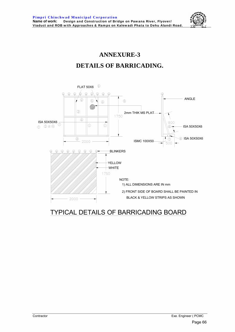
P i mp r i C h i n c h w a d M u n i c i p a l C o r p o r a t i o n Name of work: Design and Construction of Bridge on Pawana River, Flyover/ Viaduct and ROB with Approaches & Ramps on Kalewadi Phata to Dehu Alandi Road.
Contractor Exe. Engineer ( PCMC
ANNEXURE-3
DETAILS OF BARRICADING.
2mm THIK MS PLAT
FLAT 50X6
ISA 50X50X6
ANGLE
ISA 50X50X6
TYPICAL DETAILS OF BARRICADING BOARD
ISMC 100X50ISA 50X50X6
NOTE: 1) ALL DIMENSIONS ARE IN mm
2) FRONT SIDE OF BOARD SHALL BE PAINTED IN
BLACK & YELLOW STRIPS AS SHOWN
YELLOWWHITE
BLINKERS
Page 66
P i mp r i C h i n c h w a d M u n i c i p a l C o r p o r a t i o n Name of work: Design and Construction of Bridge on Pawana River, Flyover/ Viaduct and ROB with Approaches & Ramps on Kalewadi Phata to Dehu Alandi Road.
Contractor Exe. Engineer ( PCMC
ANNEXURE-4
HIGH CONTAINMENT ANTI CRASH BARRIER.
Page 67
P i mp r i C h i n c h w a d M u n i c i p a l C o r p o r a t i o n Name of work: Design and Construction of Bridge on Pawana River, Flyover/ Viaduct and ROB with Approaches & Ramps on Kalewadi Phata to Dehu Alandi Road.
Contractor Exe. Engineer ( PCMC
SECTION VI
EMPLOYER’S REQUIREMENTS
CHAPTER – v
SPECIAL CONDITIONS OF CONTRACT
Page 68
P i mp r i C h i n c h w a d M u n i c i p a l C o r p o r a t i o n Name of work: Design and Construction of Bridge on Pawana River, Flyover/ Viaduct and ROB with Approaches & Ramps on Kalewadi Phata to Dehu Alandi Road.
Contractor Exe. Engineer ( PCMC
SPECIAL CONDITIONS OF CONTRACT/SUPPLEMENTARY INFORMATION
The following conditions shall prevail:
1.0 CEMENT FOR WORKS
The Contractor shall make his own arrangement for cement. The cement shall be OPC grade 43/53 for structure by approval of Engineer. The supply of cement shall be of approved brand by the Engineer.
2.0 ELECTRIC POWER SUPPLY
The Contractor shall make all the necessary arrangement for procurement of electric power required for the work. The Contractor shall submit his requirement of Electric Power Supply for carrying out permanent works, operating plants and equipments, labourers camp and field offices etc., as a part of his work plan. The employer will issue the necessary certificates, letters of recommendation etc., to the contractor for obtaining the power supply. However, the employer shall accept no responsibility for any delays in obtaining the power connections. In addition, the contractor shall maintain standby diesel generators of adequate capacity. Non-availability of electric power will not be considered as a reason for delay in progress.
3.0 WATER SUPPLY FOR CONSTRUCTION, LABOUR CAMPS, OFFICES ETC.
The Contractor shall make all necessary arrangements for the procurement of water required for construction and labour complete. The employer shall issue the necessary certificates, letters of recommendation etc., for obtaining the necessary permissions. The employer shall assume no responsibility for delay in progress due to delay in obtaining the permissions. The Contractor may drill bore wells as a source of construction water. The water shall be got tested by the contractor at his own expense and certificates regarding the suitability for construction shall be submitted to the Engineer regularly as per his requirements.
4.0 TELEPHONES / WIRELESS COMMUNICATION FACILITIES
These will be arranged by contractor at his own cost. The employer shall give the necessary certificates and letters of recommendation etc., to the contractor.
5.0 LAND FOR TEMPORARY USE
Land for labour camps, storage yards temporary site sheds etc., will be arranged by the contractor at his own cost.
6.0 CONTRACTOR’S MATERIALS, LABOUR ETC.
The Contractor shall provide everything necessary (except for items to be provided by the Employer specifically mentioned in the conditions) for the proper execution of the works according to the intent and meaning of the Drawings, Notes, Bill of Quantities and Specifications taken together, whether the same is or is not particularly shown or described therein; provided the same can be reasonably in forced there from. If the contractor finds any discrepancy therein he shall immediately and in writing refer the same to the engineer. The decision of the engineer shall be final and binding on the contractor. Figured dimensions shall be followed and the drawings shall not be scaled from.
Page 69
P i mp r i C h i n c h w a d M u n i c i p a l C o r p o r a t i o n Name of work: Design and Construction of Bridge on Pawana River, Flyover/ Viaduct and ROB with Approaches & Ramps on Kalewadi Phata to Dehu Alandi Road.
Contractor Exe. Engineer ( PCMC
7.0 ENABLING WORKS
The Contractor shall supply, fix and maintain at his own cost during the execution of works, all the necessary centering, and scaffolding, staging, planking, timbering, strutting, shoring, pumping, fencing, hoarding, watching and lighting by night as well as the necessary equipment for protection of public and safety of any adjacent roads and railway lines. The contractor shall remove any or all such centering scaffolding, staging planking and equipment when ordered to do so by the engineer and make good all matters and things disturbed during the execution of works to the satisfaction of the engineer.
8.0 WORK ORDER BOOK
A work order book shall be maintained on the work and the contractor of his authorised representative shall acknowledge and sign the orders given therein by the Engineer and shall comply these promptly and correctly.
9.0 DISCOVERIES
In the event of discovery by the contractor or his employees, during the progress of work, of any treasure, fossils materials or other articles of value of interest, the contractor shall give immediate notice thereof to the Engineer of such treasure or things which shall be the property of the Government of India and shall not be removed by the contractor under any circumstances.
10.0 TEMPORARY DIVERSIONS, MAINTENANCE OF SAME AND TRAFFIC MANAGEMENT
In addition to provisions made in the technical specifications, it is stipulated that the contractor shall construct, maintain and carryout the traffic management including safety features, for all temporary diversions.
11.0 OPPORTUNITIES AND FACILITIES FOR OTHER CONTRACTORS AGENCIES ETC.
The contractor shall, in accordance with the requirements of the Engineer afford all reasonable opportunities for carrying out their work to any other contractors employed by the Employer and their workmen and to the workmen of the Employer and of any other duly constituted authorities who may be employed in the execution on or near the site of any work not included in the Contract or of any contract which the Employer may enter into in connection with or ancillary to the works. If, however, the contractor shall on the written request of the Engineer or Engineer’s representative make available to any such other contractor or to the Employer or any such authority any roads or ways for the maintenance of which the contractor is responsible or permit the use of by any such of the Contractor’s scaffolding or any other plant on the site or provide any other service of whatsoever nature, for any such the Employer shall pay to the Contractor in respect of such use of service such sum or sums as shall in the opinion of the Engineer be reasonable.
12.0 ENVIRONMENTAL SAFEGUARDS
The Contractor shall take action of following points and note the stipulations as under as regards environmental safeguards as stipulated by the Ministry of Environment and Forests.
12.1 Appropriate measures shall be undertaken while undertaking digging activities to avoid degradation of water quality.
Page 70

P i mp r i C h i n c h w a d M u n i c i p a l C o r p o r a t i o n Name of work: Design and Construction of Bridge on Pawana River, Flyover/ Viaduct and ROB with Approaches & Ramps on Kalewadi Phata to Dehu Alandi Road.
Contractor Exe. Engineer ( PCMC
12.2 Borrow pits and other scars created during the road construction shall be properly leveled and treated.
12.3 Adequate provision for infrastructural facilities, i.e. water supply, fuel, sanitation, etc. shall be ensured for labourers during construction period in order to avoid damage to the environment.
12.4 No excavation from or dumping of waste materials into any water body / wetlands shall be done.
12.5 Borrow sites for earth, quarry sites for road construction and dump site shall be identified keeping in view:
12.6 No excavation or dumping on private property is carried out without written consent of the owner.
12.7 No excavation or dumping shall be allowed or wetlands, forests areas or other ecologically valuable or sensitive locations.
12.8 The excavation work shall be done in consultation with soil conservation and watershed development agencies working in the area:
12.9 Construction spoil including bituminous material and other hazardous material must not be allowed to contaminate water course and the dump sites for such materials must be identified well in advances before construction and lined properly so that they do not leach into the ground water.
12.10 The trees, which are necessary to be felled should be identified before hand and necessary approval from the competent authority should be obtained for felling the same. Sufficient number of trees of suitable species should be planted in lieu of the trees felled.
12.11 A contingency plan shall be prepared to combat with accidents so that the victims of accident can be provided immediate medical help. Some essential equipment, building and other facilities may be required for the purpose.
12.12 The Employer or any other competent authority may stipulate any other condition for environmental safeguard, subsequently, if deemed necessary, which should be compiled with.
12.13 The above mentioned stipulations shall be enforced among others under the Water (Prevention and Control of Pollution) Act, 1974, the Air (Prevention and Control of Pollution) Act, 1981 the Environment (Protection) Act 1986, the Hazardous Chemicals (Manufacture, Storage and Import) Rule, 1989, the Environmental Impact Assessment (EIA) Notification 1994 and its amendment of May 1994, April 1997, January 2000, the Public Liability Insurance Act 1991 and the rules made there under from time to time.
13.0 PETROL PUMPS
The Employer may give permission to Petroleum Companies to establish Petrol / Diesel Pumps adjacent to the site of work. The suitable location shall be identified by the contractor, after which Employer will take necessary action in the matter.
14.0 REMOVAL / DIVERSION OF UTILITY SERVICE
As far as possible, the Contractor’s alternative proposal shall be such that the shifting of utility services is not required. However, if the over ground / underground utility services like electric poles, telephone poles, water supply
Page 71
P i mp r i C h i n c h w a d M u n i c i p a l C o r p o r a t i o n Name of work: Design and Construction of Bridge on Pawana River, Flyover/ Viaduct and ROB with Approaches & Ramps on Kalewadi Phata to Dehu Alandi Road.
Contractor Exe. Engineer ( PCMC
pipe lines, sewer lines, oil pipe lines, cables, gas ducts etc. owned by various authorities including Public Undertakings and local authorities encountered during construction shall be diverted by the Contractor and will be reimbursed as per the estimate prepared by the concerned PCMC department / other agency and approved by Employer. The work shall be carried out under the supervision of concerned PCMC department / other agency. In case in the opinion of the Engineer it is not possible to divert the utilities, the Contractor shall make necessary modifications in the structure at no extra cost to the client.
15.0 TAXES – Refer Clause Clause 14.1 (b) of GC.
16.0 QUARRIES
The contractor will have to make his own arrangement of acquiring land for quarries. The contractor shall carry out all quarrying operations without endangering the environment and natural beauty of surrounding.
All excess and un-useful excavated materials shall be stacked at dumping places if available, identified by the Employer as directed by the Engineer; otherwise the contractor has to make his own arrangement for the same.
17.0 Additional Obligations:-
1. Any Structure or portion of work if rejected by Employer’s Engineer has to be dismantled and removed after receipt of written advice from the Employer’s Engineer and redone or modified as per specification and drawing. Cost of which is to be borne by the Contractor.
2. The work of Railway ROB shall be carried under supervision and presence of concerned Railway Engineer or an authorized Railway supervising Engineer appointed by him. The final acceptance of the work shall be subject to his satisfaction. In case of any rejection of any such portion of work shall be dismantled by the contractor and re-done under Railway’s Supervision
3. Design Drawings / Working Drawings before releasing for work shall be submitted to Consulting Engineer appointed by the Employer for Proof Checking of Design done by Contractor’s Engineer.
4. Any discrepancy pointed by the Consulting Engineer of Employer shall be corrected and re submitted.
5. The Design and all Drawings of Railway portion of work within Railway Boundary shall be proof checked by Railway approved consulting Engineer and submitted at Design Cell of Central Railway’s Chief Engineer’s Office by the contractor for final checking and final approval. This also includes for all temporary works erected in Railway portion as well as for launching Scheme of PSC I Girders. All necessary co-ordination with Railway during approval of drawings and during execution of work shall be done by Contractor.
18.0 Special Conditions while working in the Railway Area.:-
18.1 No work within Railway area shall be done without the presence of Railway’s Engineer or Railway’s authorized staff.
18.2 No work on Railway track shall be undertaken by the contractor unless the traffic Block is sanctioned and arranged by Railway Engineer. The work shall be carried in planned way within duration of sanctioned power and traffic Block in presence of Railway Engineer.
Page 72
P i mp r i C h i n c h w a d M u n i c i p a l C o r p o r a t i o n Name of work: Design and Construction of Bridge on Pawana River, Flyover/ Viaduct and ROB with Approaches & Ramps on Kalewadi Phata to Dehu Alandi Road.
Contractor Exe. Engineer ( PCMC
18.3 During the traffic Block the railway Track shall be protected only by authorized Railway staff deployed by Railway Engineer as per Railway General and subsidiary Rules.
18.4 No Tools or Equipment or machinery or plant shall be brought or kept in side Railway area without the written permission of Railway Engineer. No tools or equipment shall be kept in side area of Railway track for safe movement of Trains.
18.5 No material shall be stacked inside Railway without written orders given by Railway Engineer.
18.6 Any excavation for foundation within 5 meters near Railway track shall be carried only after approval of Railway Engineer. The excavated area shall be barricaded by fencing and it is ensured that such barricade shall be provided at safe distance from Railway Track as per Indian Railways Schedule of Dimensions 2004 and according to specific instruction of Railway Engineer.
18.7 Contractor shall submit a launching scheme and drawing for launching of PSC I Girders with design calculation and Requirement of traffic blocks etc. for each Phase work for approval or Railways before undertaking such works. The PSC I Girders shall be provided with temporary steel brackets to secure its stability after launching till RCC diaphragms are cast which shall be shown in the launching scheme. If launching is done by Road cranes in the case capacity of the cranes shall be written in the launching scheme. Minimum three cranes shall be used out of which third crane will remain at site as stand by in case of failure of any of the working crane. In case steel launching girder is use for launching of PSC I Girders, its structural details drawing with design calculation shall be submitted by the contractor duly proof checked by Railway approved proof checking Engineer for final approval of Railway. The Drawings shall also include Shuttering Arrangement for Deck Slab.
18.8 No vehicles of contractor are permitted to ply within 15m from Railway Track. If it is required to do so, the matter shall be informed well in advance to Railway Engineer so that he may depute his authorized staff with necessary Red flag and protection equipments for such work for safety of Running trains.
18.9 The Vehicle and Crane Drivers of Contractor should have necessary Driving licence and competency certificate which shall be produced to Railway Engineer before deployment by the contractor. These drivers should have Photo Identity cards issued by the Contractor. Any Change of such staff should be brought in the knowledge of Railway Engineer in charge well in advance. Railway Engineer shall have right to demand for changing of any such staff who in his view is found incompetent and doing unsafe work in Railway area.
18.10 All staff of Contractor shall maintain Identity card while working in Railway Area. Copy of the same with list of such staff shall be submitted by the contractor to Railway Engineer well in advance. Any change of such staff for the work of Railway area should be informed to Railway Engineer well in advance.
18.11 Contractor has to deploy supervisor and site Engineer who has previous experience to work in the Railway suburban area in view of safety of running trains.
18.12 PSC I Girders shall be precast outside and then launched for the ROB by adopting method after Railway Approves Contractor’s launching scheme.
Page 73
P i mp r i C h i n c h w a d M u n i c i p a l C o r p o r a t i o n Name of work: Design and Construction of Bridge on Pawana River, Flyover/ Viaduct and ROB with Approaches & Ramps on Kalewadi Phata to Dehu Alandi Road.
Contractor Exe. Engineer ( PCMC
18.13 Railway shall neither be responsible in any way for any injury to Contractor’s staff or supervisors during the course of work nor it shall be a part for any such injury covered under workman’s compensation Act. The contractor has to train his staff to learn Railway safety Rules before deputing them to work in Railway area in consultation with Railway Engineer.
18.14 No scaffolding or ladder shall be provided without presence of Railway Engineer or his authorized staff within 7.5 meter distance from any Railway track.
18.15 While casting Deck Slab of the ROB or providing shuttering work the Contractor shall ensure that no materials or tools fall from ROB over Railway Track to ensure safety of running trains.
18.16 Flyover shall not be commissioned even after completion of the work by the contractor unless necessary formalities are completed and the contractor obtains a satisfactory completion certificate from Railway Engineer for ROB portion.
18.17 During the Defect Liability period the contractor has to attend any maintenance of the ROB as per inspection report of Railway Engineer in presence and under the supervision of Railway Engineer or a authorized supervisor nominated by him.
BïïïïïC
Page 74

201/202, Sai Empire, 3rd Floor,Baner, Pune-45
C.V. KANDC.V. KANDCONSULTANTS
PRIVATE LIMITED