intermediate robotics assignment investigating underwater ... · hydro car (rov): this vehicle is a...
TRANSCRIPT

1
1
INTERMEDIATE ROBOTICS
ASSIGNMENT
Investigating underwater inspection
robots in offshore oil and gas industry

2
2
Contents
Introduction: ............................................................................................................ 3
Objective ................................................................................................................. 5
Design conceptualization: ......................................................................................... 5
1. Hydro Car (ROV): ............................................................................................ 5
2. Gold Star (AUV): .............................................................................................. 5
Development of the design: ....................................................................................... 6
1. Body: .............................................................................................................. 6
2. Bow planes, wings and tails: ............................................................................ 6
3. LEDs and Cameras .......................................................................................... 7
4. Thrusters and Fans (small thrusters): ............................................................... 7
5. Control unit ..................................................................................................... 7
6. Inspection system (instruments): ...................................................................... 8
7. Navigation system (instruments) ...................................................................... 8
8. Power system ................................................................................................. 9
3D CAD drawings: .................................................................................................. 10
Inspection System: ................................................................................................. 11
1. LiDAR ( M-S-L by CDL underwater engineering ) and Differntial absorbtion LiDar
(DIAL) (2 in 1): ..................................................................................................... 19
2. Multibeam Sonar (Sea Beam 2100 .................................................................. 21
3. CTD sensor ( CTD NV ): .................................................................................. 23
4. Surveying Camera w/LED light (Surveyor HD color zoom camera w/MS LED) ..... 24
5. Profiling Sonar (Tritech Super SeaKing DFP Profiler): ...................................... 25
Navigation system/ Control system .......................................................................... 27
1. Inertial measurement unit (IMU ....................................................................... 31
2. Magnetometer compass ................................................................................. 32
3. Velocity sonar ............................................................................................... 33
4. GPS/DGPS .................................................................................................... 33
5. Pencil-beam sonar collision avoiding system ................................................... 33
Conclusion: ............................................................................................................ 34
References: ........................................................................................................... 34
Appendix: ............................................................................................................... 37
3
3
Introduction:
Regular underwater inspection and maintenance of offshore oil and gas platforms has now
become accepted as a major task by platform operators. It is reasonable to assume that when
oil and gas finds in deeper waters are exploited, the inspection requirements of the host
governments and certifying authorities will be no less stringent than they are for shallow-water
installations. When these deep-water fields are developed, and what-ever design of production
system is used, there will be vital items of equipment located at depths, inaccessible to divers.
The underwater inspection, maintenance and repair techniques are required which are
inaccessible to the divers because of the ocean depths (pressure) so other alternatives are
required. Further, the consequences of the limitations of these alternative techniques demand
that underwater inspection, maintenance and repair be a major consideration during the initial
design of deep-water production systems. In shallow water, underwater inspection has usually
been an afterthought on the part of platform designers.
Pipeline inspections are performed to ensure the continuing integrity of subsea pipelines.
Examples on threats to pipeline integrity are movement and bending of pipelines and water
action driven scouring which develops into long free spans. In pipeline inspection, one also
looks for damage already caused to the pipeline, for instance from trawling or from a ship’s
anchor.
Survey AUVs offer a geophysical sensor suite consisting of multibeam echo sounder
(bathymetry), side scan sonar or synthetic aperture sonar (acoustic imagery), lidars and sub
bottom profilers (shallow seismic).Due to stable and smooth movement, survey AUVs produce
geophysical data of very high quality. Compared to ROVs, AUVs survey at higher speed, thus
positively contributing to cost efficiency. Contrary to tow fish, AUVs can operate for long
distance s below the surface vessel. This benefits the accuracy of acoustic positioning system
and is the primary reason for the unparalleled position accuracy that is obtained with AUVs.
AUVs track the bottom at a constant altitude optimal for its geophysical survey suite throughout
the whole dive.
Whether the application is geophysical survey of the seabed or pipeline inspection, the end
customer's primary interests are the data products, not the sensor platform. Recent sensor
developments are thus the key enablers for possible use of AUVs for pipeline inspection.
Multibeam echo sounders (MBE) are normally used for bathymetric surveys. For an AUV, the
MBE can also be a primary sensor for automatic tracking of the pipeline. High-quality
underwater optical camera solutions with low power LED lightning to save battery life is now
available for AUVs. When equipped with forward looking sonar for improved bottom following,
AUVs can in most areas be operated within visual range of the pipeline. Laser camera provides
extended range compared to an underwater camera. Other sensors useful in pipeline inspection
4
4
operations could be sonar and sniffers for leakage detection. The combination of pipeline
inspection and environmental surveillance could be of interest many areas.
AUVs are physically free to perform autonomous operations. However, endurance is limited by
battery capacity, and a surface asset will in most cases be required. In geophysical seabed
mapping operations, the AUV is often followed by a surface vessel with GPS and acoustic
positioning system for optimal position accuracy. An AUV system can have a relatively small
footprint that can allow for smaller surface vessels and lower operational cost, at the sacrifice of
more weather dependent operations. For a pipeline inspection system with automatic tracking,
the requirements on absolute position accuracy is less than in detailed seabed mapping. Even
though the integrated inertial navigation system position accuracy typically drifts 10 m per hour,
this does not affect the tracking system and the position drift is accurate enough to detect
bending of the pipeline. The AUV can inspect the pipeline autonomously at high speed .In
shallow and coastal waters, smaller AUVs are attractive because of easy handling and
mobilization on small boats. In deeper and more remote areas, larger AUVs with more capable
sensors and longer endurance is required as a key point is to make operation of the complete
system of surface asset and AUV cost efficient. An interesting prospect is deployment of AUVs
either on floating production units or in docking stations in subsea oil and gas production fields.
Benefits will be an always present and ready inspection capability, allowing for both planned
inspections and rapid inspections in case of emergencies. Especially in remote areas and under
ice, mobilization time and cost will be greatly reduced since no surface vessel will be required.
(http://www.sciencedirect.com 10 Nov, 2009)
(http://www.ngoilgas.com/article/Pipeline-Inspection-with-Autonomous-Underwater-Vehicles/ 8
Nov, 2009)
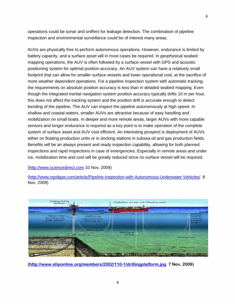
(http://www.ehponline.org/members/2002/110-1/drillingplatform.jpg 7 Nov, 2009)

5
5
Objective:
To construct a robot which can inspect underwater (deep sea) oil and gas pipelines for any
leakages or cracks. This is because oil and gas are very important and expensive natural
resources. Their loss due leakage of pipelines or crack developed in pipelines over time can
cause huge monetary loss to company who deployed these pipelines for oil and gas transfer
over long distances. So, as to prevent this from happening we need to inspect the pipelines.
Keeping this in mind we develop a robot to tackle these problems.
Design conceptualization:
1. Hydro Car (ROV): This vehicle is a remotely operated so, the control system is
ROV. We have a user at a remote location from the ROV as a ship. The data transfer
occurring between user and the ROV is with the help of copper umbilical cords whose
male end is connected to the user’s controller and the female end to the ROV through
the jack on it behind. The ROV inspects the pipeline using the latest laser technology
for the defects. The ROV is equipped with the variable buoyancy device (can be used
to make ROV go up and down but not specific way) and 2 mini thrusters on its behind
for movement in forward direction. We have camera with halogen lamps attached on its
front giving clear view for remotely placed user navigating the ROV. Our ROV can float,
swim or run on the ocean surface using it specially designed tyres which have dual
functions. Tyres have inbuilt thrusters on its inner surface and rubber on its outer
surface. When it needs to run on the ocean surface it uses the rubber tyres which are
at vertical position but when ROV needs to swim or float the tyres tilt horizontally to
push the ROV up and down using thrusters inbuilt in tyres. We have CTD sensor
attached to it so that user can know the conductivity, temperature and depth of water
the ROV is operating. We use nickel cadmium rechargeable batteries for the ROV
operation. Its recharged using the power cable attached to its behind. The body of the
ROV is made from carbon fiber so that it remains light. Other important navigation and
control devices are placed under its hood.
2. Gold Star (AUV): This vehicle is autonomously controlled so, the control system is
AUV. This vehicle works autonomously so need no human intervention for the
inspection purpose. The data transfer occurring between the AUV and the user on the
ship or any remote location is through wireless modem inside the control unit of AUV.
The user gets the info from the receptor on his side. The AUV consist of super intensity
multi-leds on the bow plane with hd color zoom camera on its front. Both together helps
user to see the pipelines and the area surrounding pipelines crystal clear. We use Lidar
or Sonar technology for detection of cracks. Any of the 2 technologies can be chose for

6
6
the inspection purpose. Both Lidar and Sonar are present underneath the AUV. The
AUV moves up and down using the wings and fans on the bottom. The wings can tilt as
required by AUV, if it wants to come down wings move up and if wants to go up wings
move down. We have 3 powerful thrusters placed on the AUV.2 on the wings and one
on top of the AUV for forward motion with high speed. For turning left or right we have
fans (small thrusters) on either side of AUV plus the wings can tilt just like in aero plane
to move the AUV in direction desired. The frame is made of pure titanium to with stand
high pressure. The frame is covered with syntactic foams which have micro balloons in
it to make the body light (buoyancy). We use polymer electrolyte fuel cells along with
metal hydride system for giving AUV the power it needs for it operation for long period
of time. All the navigation and control systems along with the inbuilt antennas and
sensors are place in the control box which is at top forward of the AUV.
Development of the design: The vehicle developed by us, the GOLDSTAR is an autonomous underwater vehicle which
means it can work by its own. It does not require user to control it remotely or any other way.
The mission objectives, various commands and autonomous controller (software) is put into its
embedded pc. We need near perfect design and systems for inspecting pipelines in deep
oceans as; even a small mistake becomes a blunder at these depths. Now let us start
explaining the features in our AUV. They are as follow:
1. Body: The AUV has stream line body for better hydrodynamics. So that there is least
possible drag on it. The main frame of the AUV is made from Titanium which is very
tough, corrosion resistant, has low density and has long durability. The outside body is
made of frp fairing covers or the fiber reinforced polymer fairing covers. Which is an
advance material with high durability, strength and has extremely low density. For
making the body light we use buoyancy material as syntactic foam which has micro
balloons in it. The wings, rudder and tail is made of fiber glass.
(http://www.csa.com/discoveryguides/titanium/overview.php 12 Nov, 2009)
(http://www.polo-motorrad.de/shop/Technical-Customising-styling-Fairing-windshields-
Fairings/product/329192/group/7695/L/2/Search.448.0.html 12 Nov, 2009)
2. Bow planes, wings and tails: These help the AUV to cut through water easily, at
higher speeds and to change direction of the AUV or navigate in the water. The bow
planes, wings and the tail help in changing directions of the AUV by changing their
positions. When AUV wants to go up the bow planes, wings and tails slants down for
cutting up through water , similar for coming down just the bow planes, wings and tails
slant up for easy and stable descent and for turning right or left the bow plane and wing
fall down or go up from mean position just as in an aero plane.
7
7
(http://www.toodoc.com/AUV-Hydrodynamic-Design-ebook.html 8 Nov, 2009)
3. LEDs and Cameras: We use 6 multi-LEDs placed on the bow planes on both sides.
These are high intensity LEDs which are able to brighten up the area surrounding them
to a large range. Plus can be used as recovery strobe light if lost or when going to be
docked.
We use HD zoom color cameras which are places on extreme top front of the AUV.
Along with the LEDs functioning, user has wide range of view and can see the pipeline
being inspected and the surrounding area crystal clear with good brightness.
(http://www.deepsea.com/pdf/specs/WebSpec_LML_4018_120508.pdf 10 Nov, 2009)
(http://www.bowtech.co.uk/Downloads/Cameras/SURVEYOR-HD.pdf 10 Nov, 2009)
4. Thrusters and Fans (small thrusters): We use 3 powerful thrusters and 4 fans
for changing the positions of AUV. 1 thruster is placed on right and left wing each and 1
thruster is placed on top back of the AUV (for giving boost). These thrusters give
enough power to the AUV to move forward and fast.
2 fans (small thrusters) are placed at underneath behind of the AUV to move it up or
down and the other 2 are placed on right and left forward side each which help the AUV
to move in the direction desired.
(http://censam.mit.edu/news/posters/hover/1.pdf 12 Nov, 2009)
(http://www.tsltechnology.com/marine/thrusters.htm 12 Nov, 2009)
5. Control unit: It looks like a cockpit on the AUV. This one of the most important
feature of our AUV. It has the embedded pc (control system) along with various other
equipment inside it as,
Datum by CDL: Acronym for digital acoustic transponder and underwater
modem. It uses state of art spread spectrum and digital signal processing
technology to offer long range high speed device for use in ranging and data
application in deep water. Each unit is uniquely addressable and system is
networkable. Data can be sent or received from any datum in the network. It acts

8
8
as the source of data transfer from the AUV to the user on the ship or remote
location using datum.
Micro vision by CDL: It is multi-channel 2.4 GHz long range full color video
transmission system. High quality 5.6’’ LCD monitor is built into receiver unit. Is
used with our cameras to send the pictures or the video to the user.
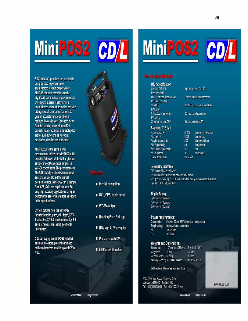
MiniPOS2 by CDL: Appendix (2nd Choice)
TOGS by CDL: Appendix
MiniRLG2 by CDL: Appendix (2nd Choice)
Minisense by CDL: Appendix (2nd choice)
Minitilt by CDL: Appendix (2nd Choice)
TCM2 : (1ST Choice)
CTD NV: It’s a sensor used for measuring conductivity, temperature and depth
where AUV is present.
DGPS
6. Inspection system (instruments): We give user an option to choose from 2 main
inspection technologies present which are Lidar and Sonar. We use Lidar and Dial (front
underneath the AUV-2), multi-beam sonar (underneath the AUV -2 arrays), profiling
sonar (front underneath the AUV-2), HD cameras and CTD sensors for inspection
purpose. They are explained in details further.
7. Navigation system (instruments): We use various instruments to be sure of the
position (co-ordinates), motion and the route of AUV. They are INU (inside control unit),
magnetometer compass (inside control unit), DVL sonar ( inside control unit) and pencil
beam sonar (on front face ).
9
9
8. Power system: We use polymer electrolyte fuel cell rating 4kw, 120v along with
oxygen gas tank 14.7 mpa and a metal hydride system to power the AUV. It is one of
the most advance and non-polluting source of energy. It is present behind the control
unit.
All these features combine together to make our AUV able to inspect the oil and gas
pipelines under water at great depth with great efficiency. When the AUV is released
from its dock it starts diving sown to reach the pipelines using its stream line body along
with the wings, bow planes and the tail. The CTD sensor keeps on measuring the
respective fields while going all the way down to the pipelines. The body is made from
such a material that when it reaches the ocean floor or near ocean from where pipeline
is present and pressure is extremely high, it is able to function effectively and efficiently.
The control unit takes over the AUV (GOLDSTAR) as soon as it is released from the
dock. It takes the route and reaches the exact point where pipeline is present and starts
inspecting the pipeline autonomously. The cameras and LEDs come handy at this time
to see exactly where AUV is and how is it progressing. The sonar or lidar systems which
ever used starts inspecting the pipelines for the leakages or cracks. The AUV swims
over the pipeline inspecting at fast speed using the thrusters and can move sideways or
up and down if required using the fans (small thrusters) and the bow planes, wings and
tail. All this data is sent to the user using the datum modem and micro vision at high
speed. The IMU, magnetometer, DVL velocity sonar, DGPS and pencil beam sonar
collision avoiding systems helps the AUV to navigate easily and efficiently while
inspecting without getting lost or hit. The various data collected from navigation
instruments are send to the user to review exactly how the AUV is performing
underwater inspecting pipelines. This also helps user to keep track of the AUV and its
surrounding conditions all the time.

10
10
3D CAD drawings:
(3D model of our AUV GOLDSTAR – front top 3D view)
11
11
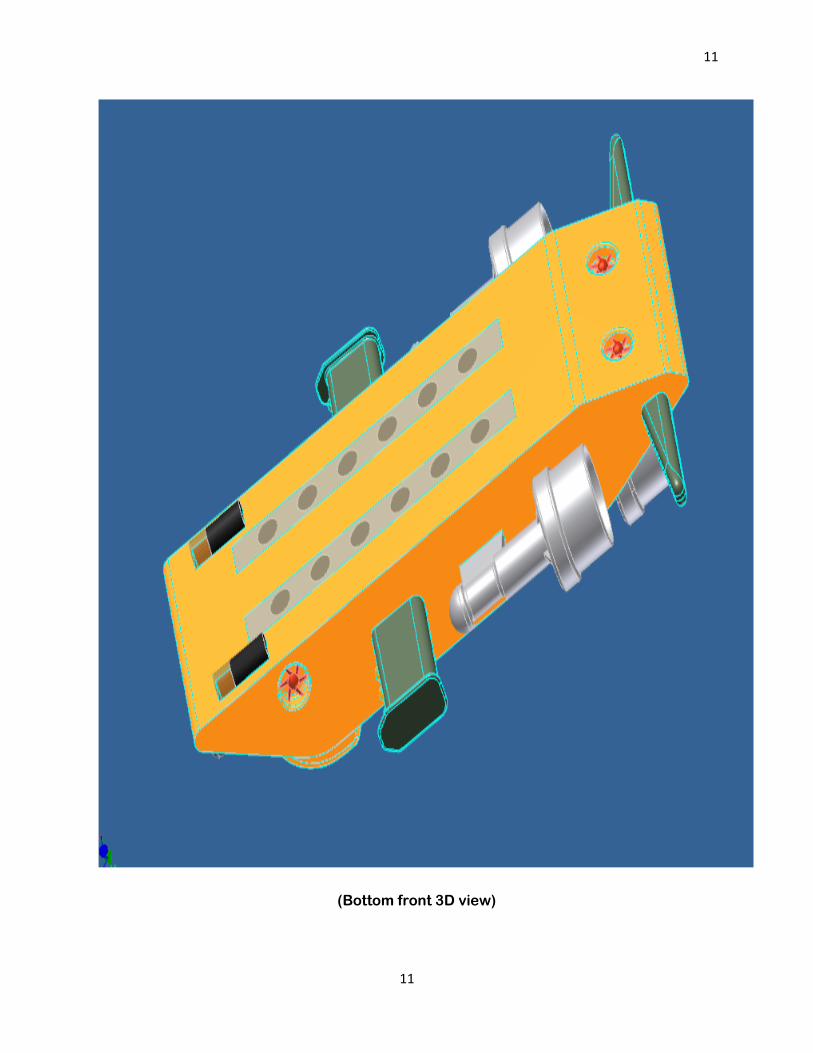
(Bottom front 3D view)

12
12
(Bottom view)

13
13
(Side view)

14
14
(Front face view)

15
15
(Top view)

16
16
(3D drawings)

17
17
(Various views projected)

18
18
(Basic dimensions shown in the drawing)

19
19
Inspection System:
We use 5 different technologies for inspection of the underwater pipelines to be 100% sure of
the results. The technologies used for detection by our AUV are as follow:
1. LiDAR ( M-S-L by CDL underwater engineering ) and Differential
absorbtion LiDAR (DIAL) (2 in 1): Light Detection and Ranging System, typically
defined as integration of 3 technologies into 1 system capable of acquiring data to
produce accurate digital elevated models (DEMs). These technologies are laser, Global
positioning system (GPS) and inertial navigation systems (INS). Combined they allow
positioning of footprint of the laser beam as it hits an object, to high degree of accuracy.
Lasers themselves are very accurate, and can provide distances accurate to few
centimeters. The limitation of the LiDar system is due to GPS and IMU (inertial
measurement unit) components. As advancement in GPS and IMU occur, it is becoming
possible to obtain high degree of accuracy from Lidar system using moving platforms as
AUV’s.
A LiDAR system combines a single narrow-beam laser with a receiver system. The laser
produces an optical pulse that is transmitted, reflected off an object, and returned to the
receiver. The receiver accurately measures the travel time of the pulse from its start to
its return. With the pulse travelling at the speed of light, the receiver senses the return
pulse before the next pulse is sent out. Since the speed of light is known, the travel time
can be converted to a range measurement. Combining the laser range, laser scan angle,
laser position from GPS, and laser orientation from INS, accurate x, y, z ground
coordinates can be calculated for each laser pulse.
(http://www.ambercore.com/files/TerrapointWhitePaper.pdf 10 Nov, 2009)
In DIAL (maybe not that useful in ocean), a pulse of laser radiation with the wavelength
λ0 is directed toward the sounded object using a transmitting-receiving lens .In the
atmosphere including the region adjacent to the gas or oil pipeline, laser radiation is
scattered by molecular components of water. The scattered radiation propagates every
which way including a rearward direction toward the transceiver. One of the processes
contributing to the light scattering is Raman scattering, which manifests itself in the fact
that in the spectrum of the radiation scattered by water, the spectral lines with the
wavelengths λi appear that are shifted relative to the sounding radiation line. This shift is
the spectral characteristic of the gas molecules or oil molecules present in the gas
mixture or liquid mixture of the sounded atmospheric volume, and their intensities are
proportional to concentration of corresponding gas or liquid.
Thus the spectral analysis of light scattered by a certain atmospheric volume enables
qualitative and quantitative determining the composition of gas mixture or liquid mixture
in the sounded atmospheric volume. In accordance with this principle, detection of leaks

20
20
in gas or oil pipelines is performed by observation of the spectral line of methane or oil
compound in the Raman spectrum of light scattered by the water adjacent to pipeline.
For this purpose, a pulse of laser radiation with the wavelength λ0 is directed toward the
pipeline. Radiation scattered in the rearward direction is collected by the transceiver lens
and
directed to the input of spectral device using a flexible optical monofiber. In the spectral
device, the light arrived at its input is decomposed in the spectrum, from which a spectral
Raman line of methane or oil compound is selected using another flexible optical
monofiber. Then, this radiation arrives at photo detector that transforms the signal in a
digital form using an electron system of recording
of LiDAR response. Application of pulse sounding radiation in the LiDAR enables
selecting signals from required atmospheric volume adjacent to pipeline using the time
passing from the moment of sending the pulse in the atmosphere up to the incoming of
scattered radiation. For this purpose, a synchronization pulse produced in the laser
system is used for initial startup of the system of
lidar response recording. Computer software makes it possible to analyze the photo
detector signal and produce the signal announcing the presence of a leak as soon as the
photo detector signal generated by the Raman line of methane or oil compound arrives
from the atmospheric volume adjacent to pipeline.
(http://trs-new.jpl.nasa.gov/dspace/bitstream/2014/14442/1/00-0879.pdf 10 Nov,
2009)
(http://www.spectrasyne.ltd.uk/html/technique.html 10 Nov, 2009)
Using the techniques explained above we can find if the leakage has occurred and also
find exact point where leakage has occurred.
Benefits of using LiDAR:
1. Rapid coverage and data output
2. High resolution images
3. Highly accurate and detailed images
4. 3-D or 2-D images got as required
5. Day and night operation
6. Economical

21
21
7. Multiple uses e.g. flood risk, aerial surveys etc
(http://www.isprs.org/congresses/beijing2008/proceedings/3b_pdf/62.pdf
11 Nov, 2009 )
2. Multibeam Sonar (Sea Beam 2100): Sonar is an abbreviation for Sound
Navigation and Ranging. It is a system that uses transmitted and reflected underwater
sound waves to detect and locate submerged objects or measure the distances
underwater. It has been used for submarine and mine detection, depth detection,
commercial fishing, diving safety and communication at sea. The Sonar device will send
out a subsurface sound wave and then listens for returning echoes, the sound data is
relayed to the human operators by a loudspeaker or by being displayed on a monitor.
There are 2 types of Sonar, which are as follow:
1. Active sonar creates a pulse of sound, often called a ping, and then listens for
reflections of the pulse. The pulse may be at constant frequency or a chirp of
changing frequency. If a chirp, the receiver correlates the frequency of the reflections
to the known chirp. The resultant processing gain allows the receiver to derive the
same information as if a much shorter pulse of the same total power were emitted. In
general, long-distance active sonars use lower frequencies. The lowest have a bass
"BAH-WONG" sound. To measure the distance to an object, one measures the time
from emission of a pulse to reception.
2. Passive sonar listens without transmitting. They are usually military (although a few
are scientific). Passive sonar systems usually have large sonic databases. A
computer system frequently uses these databases to identify classes of ships,
actions (i.e. the speed of a ship, or the type of weapon released), and even particular
ships.
( http://www.wisegeek.com/what-is-sonar.htm 11 Nov, 2009 )
( http://inventors.about.com/od/sstartinventions/a/sonar_history.htm 11 Nov, 2009 )
A multibeam sonar is an instrument that can map more than one location on the
ocean floor with a single ping and with higher resolution than those of conventional
echo sounders. Effectively, the job of a narrow single-beam echo sounder is
performed at several different locations on the bottom at once. These bottom
locations are arranged such that they map a contiguous area of the bottom usually a
strip of points in a direction perpendicular to the path of the survey vessel. This area
is called a swath. The dimension of the swath in the across track or a thwart ship
direction (perpendicular to the path of the ship) is called the swath width, and it can
be measured either as

22
22
a fixed angle or as a physical size that changes with depth. The swath width of
multibeam sonar is shown below:
Clearly, this is highly advantageous. Multibeam sonar can map complete swaths of
the bottom in roughly the time it takes for the echo to return from the farthest angle.
For a 120 degree swath system, this time is twice the ping cycle time of a single-
beam sounder, but such a system typically provides over 100 soundings as opposed
to only one. Because they are far more complex, the cost of multibeam sonar can be
many times that of single-beam sonar. However, this cost is more than compensated
by the savings associated with reduced ship operating time. As a consequence,
multibeam sonar are the survey instrument of choice in most mapping applications,
particularly in deep ocean environments where ship operating time is expensive.
( http://www.water.ca.gov/levees/evaluation/docs/bathy_factsheet.pdf 11 Nov, 2009
)
(http://www.ldeo.columbia.edu/~vschmidt/Presentations/An%20Introduction%20to%2
0Multi-Beam%20Sonarv4_files/frame.htm 11 Nov, 2009 )
The multibeam sonar system has a single transducer, or pair of transducers, that
continually transmit numerous sonar beams in a swath or fan-shaped signal pattern
till 120 degrees. This makes the systems ideal for mapping large areas rapidly, with
essentially 100 percent bottom coverage. Multibeam signal backscatter information
can be used to generate side scan data for imaging bottom features and targets in a
wide variety of water depths. The coverage area of these systems is a function of
water depth and number and pattern of beams. Most systems provide coverage
ranging from two to approximately seven times the water depth. The number of
beams also varies with the manufacturer and ranges from 30 to more than 240,
however, the outer beams on each side of the swath are subject to more errors and
may not be useful. Because of the increased density of soundings with multibeam
systems, it is possible, with proper calibration and adjustments, to detect and resolve
smaller objects on the bottom relative to single beam systems.
( http://www.tritech.co.uk/products/products-eclipse.htm 10 Nov, 2009 )

23
23
(http://www.erdc.usace.army.mil/pls/erdcpub/docs/erdc/images/ERDC_FS_Capabilit
y_MultiBeamSurvey.pdf 10 Nov, 2009)
When multibeam sonar (AUV) surveys the pipeline , if there is any crack in the
pipeline it can be shown onto the human controllers screen in the ship which gets its
information from the multibeam sonar down on the AUV. The crack is seen in
different color as compared to the whole pipeline.
Benefits of using Multibeam Sonar:
1. Increased bottom coverage
2. Higher resolution of bottom features
3. Improved target identification
4. More coverage in difficult areas (e.g. under pipeline, under barges etc )
5. Improved change detection of bottom conditions
6. 3-D modeling of downed platforms and other subsea assets
(http://www.erdc.usace.army.mil/pls/erdcpub/docs/erdc/images/ERDC_FS_Capa
bility_MultiBeamSurvey.pdf 11 Nov, 2009)
3. CTD sensor (CTD NV): CTD stands for Conductivity, Temperature, and Depth it
is the primary tool for determining essential physical properties of sea water. It gives
scientists a precise and comprehensive charting of the distribution and variation of
water temperature, salinity, and density.
Conductivity of a substance is defined as ability or power to conduct or transmit
electricity, heat or sound. It is important to know it, as for data transfer via wireless
method from AUV to human controller’s system.
Temperature sensor helps to know the temperature of the surrounding water at
various depths. It is important to know it for proper functioning of various equipments.
Depth sensor helps to know the depth where AUV is present. It is important to know
it, as human controller needs to know at what depth the AUV is, as pressure is very
important field to consider at ocean depths.

24
24
(http://www.whoi.edu/instruments/viewInstrument.do?id=1003 10 Nov, 2009)
(http://www.rdinstruments.com/pdfs/citadel_ctd-product-guide.pdf 10 Nov, 2009)
Benefits of using CTD sensor:
1. Remote sensing
2. Very accurate
3. Light weight
4. Can be used at deep depths
5. Real time mode (optional) via wireless
(http://www.swstechnology.com/groundwater-monitoring/groundwater-
dataloggers/ctd-diver 10 Nov, 2009)
4. Surveying Camera w/LED light (Surveyor HD color zoom camera
w/Multisealite LED ): Bowtech’s surveyor high definition (hd) underwater color
zoom camera utilizes sony’s latest block camera incorporating 1/3 inch hd cmos ccd
giving exceptional picture quality, 10:1 optical zoom lens as well as horizontal
resolution of 800+ TV lines. Standard video output are however HD-SDI or a large
selection of other outputs are available as options. A unique feature of this camera,
apart for the exceptional picture quality, is its size. Housed in Titanium 6000 meter
rated housing with optically clear Sapphire window, the camera is no smaller than a
standard underwater color zoom camera and therefore ideal for mounting on all
AUV’s. This camera is used to see real time images and video of the underwater
pipelines which are being inspected by the AUV. It also helps the human controller in
navigation of AUV if needed. For providing clear images and video for the human
controller we have installed multi-sealite LEDs on the bow planes of our AUV. These
LEDs have life span of 50,000 hours and are incredibly shock and vibration resistant.
These LEDs provide 5-6 times more light per watt than comparable halogen lamps.
(http://www.bowtech.co.uk/Downloads/Cameras/SURVEYOR-HD.pdf 11 Nov, 2009)

25
25
(http://www.deepsea.com/pdf/specs/WebSpec_LML_4018_120508.pdf 11 Nov,
2009)
5. Profiling Sonar (Tritech Super SeaKing DFP Profiler): Profiling sonar
provide an accurate cross-sectional profile of the seabed surface which highlights
any structural differences and objects on the seafloor. Typically, profiling sonar will
be used for cross sectional profiling in pipeline and trench survey, precision
positioning of mattresses and rock dumping, storage tank survey and the underwater
survey of manmade structures including road and rail bridge foundations.
Profiling sonar is horizontally mounted on survey vessel, pointing the transducer
vertically downwards towards the seabed. They are usually in pairs, fixed to the port
and starboard sides of the survey vessel. Profilers operate by rotating a transducer
attached to a stepper motor through a number of angular ping positions within a
defined scan width. Between successive ping positions there is a fixed step angle
which is dependent on the resolution setting of the profiler head. Reducing the fixed
step angle size will improve image resolution but increase overall scan time as the
profiler will take more data samples during the scan.
Once at the ping position, the profiler sends a narrow conical-shaped acoustic beam
of energy toward the seabed. Some of this acoustic energy is reflected back to the
profiler and the travel time of the acoustic pulses are recorded together with
amplitude information. Once the ping is complete, timing out at the time equivalent of

26
26
the range scale setting, the profiling sonar will send the peak echo return to a topside
console for interpretation and display. Only the travel time is sent along with the
transducer bearing, this is the only information that is required in order to plot a
cartesian point on the surface display. The profiling sonar can be configured to send
either the peak echo that is detected within the range scale setting or the first echo
return that is measured over a detect threshold level. For the latter setting, this will
improve scan times since when the profiler receives this first echo return, it will
ignore all further echo returns, move to the next ping position and commence with
the next acoustic ping immediately. This will result in a time saving with not having to
sample echoes for the remainder of the range scale setting.
There can be one or more profiler heads used in a system. The profiler heads can be run in single or dual head modes. A dual head profiler system will have two individual profiling sonar heads connected, one as a master profiler and one as a slave profiler. A synchronization link is setup between a dual head profiler pair. When the profiler pair is linked, the master profiler is responsible for taking control of the profiler pair and establishing scan and ping synchronization. When the profiler pair is operating in scan sync mode, both master and slave profiler heads will start scanning at the same time. When the profiler pair operates in ping sync mode, the master and slave profiler heads will ping alternately. This is to ensure there is no cross interference when the scan paths of both profiler heads meet. There is also the option to set the slave profiler head to mirror the master profiler. This has two purposes. Firstly, the scan Direction of the Slave profiler will be opposite to that of the Master profiler. Secondly, when adjusting the centre scan direction of the master profiler, the slave profiler centre scan direction will be adjusted in the opposite direction. Both profiler heads in a dual head profiler system can still be run in single head mode if required.

27
27
(http://www.tritech.co.uk/products/info/products-info-profiling_sonars.htm12 November 2009)
(http://www.sharkmarine.com/sonar.htm 12 Nov, 2009)
The multibeam sonar can work together with profiling sonar to give best results possible by sonar. As profiling sonar can look up to 50 meters under the sediments on the sea floor, it helps to survey or inspect pipeline over which sedimentation has occurred. Using the sonar technology we can inspect the pipelines at a high speed and places which are hard to access by an AUV. Our AUV can also have side-scan sonar for the best result possible by sonar systems.
(http://www.omg.unb.ca/omg/papers/galway.pdf 12 Nov, 2009)
Our AUV can use various technologies for inspection of underwater pipelines. We give its users freedom to use which technology would they like to use for their surveying and inspection system. They can use various LiDAR systems or various Sonar systems. It’s neither easy nor economical to use multiple systems at once. Hence we recommend it’s users to use any one of the 2 technologies specified.
Navigation system/ Control system: Below we have explained the navigation
systems and control system chosen in detail.
Navigation is the science or art of conducting ships or vessels from one place to another,
including, more especially, the method of determining a ship's position, course, distance passed
over etc ,on the surface of the globe, by the principles of geometry and astronomy. (Basic
definition)
(http://www.definitions.net/definition/navigation 12 Nov, 2009)

28
28
The controller is the robot's brain and controls the robot's movements. It's usually a computer of
some type which is used to store information about the robot and the work environment and to
store and execute programs which operate the robot. The control system contains programs,
data algorithms, logic analysis and various other processing activities which enable the robot to
perform.
The picture above is an AARM Motion control system. AARM stands for Advanced Architecture Robot and Machine Motion and it's a commercial product from American Robot for industrial machine motion control. Industrial controllers are non-servos, point-to-point servos or continuous path servos. A non-servo robot usually moves parts from one area to another and is called a pick and place robot. The non-servo robot motion is started by the controller and stopped by a mechanical stop switch. The stop switch sends a signal back to the controller which starts the next motion. Point-to-point servo moves to exact points so only the stops in the path are programmed. A continuous path servo is appropriate when a robot must proceed on a specified path in a smooth, constant motion.
More sophisticated robots have more sophisticated control systems. The brain of the Mars Sojourner rover was made of two electronics boards that were interconnected to each other with Flex cables. One board was called the CPU board and the other the Power board and each contained items responsible for power generation, power conditioning, power distribution and control, analog and digital I/O control and processing, computing and data storage.
Mobile robots can operate by remote control or autonomously. A remote control robot receives instructions from a human operator. In a direct remote control situation, the robot relays information to the operator about the remote environment and the operator then sends the robot instructions based on the information received. This sequence can occur immediately (real-time) or with a time delay. Autonomous robots are programmed to understand their environment and take independent action based on the knowledge they poses. Some autonomous robots are able to learn from their past encounters. This means they can identify a situation, process actions which have produced successful/unsuccessful results and modify their behavior to optimize success. This activity takes place in the robot controller.
(http://prime.jsc.nasa.gov/ROV/systems.html 12 Nov, 2009)
1. We use autonomous control system for inspecting the pipeline that is an AUV.
The autonomous unmanned underwater vehicle (AUV) is an automatic self- propelled platform of research instrumentation which is able to dive into the preset area of the ocean at a depth up to 6000 m, move along the programmed trajectory, and perform necessary operations and at the end of program return to the support vessel or base point.

29
29
The AUV operates under water independently without the umbilical. Transmission of instructions on-board the vehicle and video information back is accomplished by means of acoustic communication link. The acoustic positioning system together with integrated on-board navigation system allows determining continually the vehicle location whereas an operator of support vessel is able to track the trajectory of the vehicle motion in real time. The time of AUV continuous operation under water depends upon the vehicle design and type of power source and may amount from units to several tens of hours. The instruments installed on the vehicle include sensors for measuring environmental parameters, photo and video cameras, sonar etc. The modular construction of AUVs was used to allow for easily modification of the vehicle for concrete operational task. The efficiency of operations performed by the towed or tethered vehicles lowers abruptly with an increase in depth. The autonomous underwater vehicle characterized by considerably greater maneuverability than a ship and high accuracy of stabilization of the motion parameters (including conditions of rough bottom relief) as well as by simplicity of exploitation has the efficiency independent of depth.
The main fields of AUV application:
•ocean exploration and monitoring of water medium marine geological survey
•inspection of the underwater engineering structures and pipelines
•search, inspection and rescue operations
•protection of environment and maricultures
(http://www.imtp.febras.ru/anpa/anpa_.html 9 Nov, 2009)
3 main objectives AUV must complete:
A higher quality of data compared with towed sensors, which is the result of carrying the sensors nearer to the seabed
A reduction in project time by reducing significantly the turn-around time at the end of each survey line compared with towed sensors
A reduction in project cost as a result of smaller survey teams, the capability of operating from smaller vessels that are less costly than DP or conventional large survey vessels, and by better-informed engineering decisions by client management based on the higher quality data.

30
30
(http://www.underwater.com/archives/arch/julyaugust01.08.shtml 9 Nov, 2009)
We have various control modes for operation of our AUV as:
1. The basic control modes had already been implemented in the system. On loading the operator interface the user is in the control mode, disconnected. Once the user establishes a connection to the server, the control mode switches to the observer mode. At this particular stage, the user can only view state information that is received from the robot.
2. On selecting individual control mode, the user can manipulate the state of the camera and the motors on the robot.
3. The teleoperation control mode provides navigation mechanisms to the robot. That
is, also user to navigate.
4. Supervisory control mode is supposed to allow the user to plan or map a route for the robot, or execute a series of commands in sequence.
(http://users.rsise.anu.edu.au/~rsl/rsl_papers.html 10 Nov, 2009)
2. With recent advances in battery capacity and the development of hydrogen fuel cells, autonomous underwater vehicles are being used to undertake longer missions that were previously performed by manned or tethered vehicles. As a result, more advanced navigation systems are needed to maintain an accurate position over a larger operational area. The accuracy of the navigation system is critical to the quality of the data collected during survey or inspection missions and the recovery of the AUV. Many different methods for navigation in different underwater environments have been proposed in the literature. We have used state of the art in navigation technologies for our AUV. The navigation technologies used by us and their comparison with other technology are explained in below: One solution for autonomous underwater navigation is to make use of an array of long-base-line (LBL) acoustic beacons such that the vehicle position can be estimated by means of triangulation. The LBL solution requires the beacon array to be either mounted on the ocean bottom or moored on the surface (inverted LBL), and thereby restricts the AUV coverage area to be within the beacon grid. In addition, the performance of this

31
31
externally aided positioning depends largely on the sound-speed profile in the water column. For multiple AUV operations, independent sets of beacons must be installed, and this rapidly increases the logistical complexity of a mission. Dead reckoning (DR) aided with doppler velocity measurement has been, and remains, the most common method for underwater navigation. In the DR mode, the vehicle relies on its set of navigation instruments to estimate the vehicle’s position. These instruments include a three-axis accelerometer and gyroscope, a flux-gate compass, and doppler velocity log (DVL) sonar. The system is commonly referred to as a doppler-aided inertial navigation system (INS) as most of these instruments rely on the inertial properties of gravity and magnetic field. The DR solution does not measure directly the vehicle’s position, but instead estimates it by integrating the velocity and bearing measurements with respect to time. Any measurement errors in velocity and heading will thus result in a growing position error, up to a threshold beyond which the navigation performance becomes unacceptable. For this reason enhanced INS system has been developed. This navigation system consists of a (Mini RLG2) inertial measurement unit (IMU), together with a GPS/DGPS receiver, a TCM2 flux-gate compass, and DVL sonar. A navigation system is commonly referred to as INS when it uses only inertial sensors to estimate its attitude, velocity, and position. Besides gyroscopes and accelerometers, our system makes extensive use of DVL and GPS data and would be more appropriately labeled as Doppler-aided/GPS-aided INS. However, for simplicity, we simply refer it to as INS. A suite of data fusion and correction methods that combine all available asynchronous measurements has been implemented. These methods include a complementary filter for estimating the vehicle attitude, a deviation table for correcting the compass bias, and an extended kalman filter (Mini POS2) or estimating the vehicle position and heading. With improved underwater navigation accuracy, the overall performance of a mission can be made more efficient because it requires fewer surfacing maneuvers (for acquiring GPS fixes) for a given position-error tolerance. Now we explain the navigation instruments used by our AUV in detail:
1. Inertial measurement unit (IMU): An IMU consists of a three-axis gyroscope
and a three-axis accelerometer. A single-axis gyroscope measures the angular rate of change of a platform about its main axis of rotation whereas a single-axis accelerometer measures the linear acceleration of a platform together with the gravity along its axis of translation. Both sensors measure the motion relative to an inertial frame of reference. Four gyroscope technologies are available: mechanical, solid state, fiber-optic (FOG), and ring-laser (RLG). A mechanical gyroscope uses the inertia of a very fast spinning ball to detect any angular change about its axis. Solid-state gyros are operated based on the principle of the Coriolis Effect, which is when a translating body is subject to angular rotation, the Coriolis force experienced is proportional to an applied angular rate the operational principles for both FOGs and RLGs are very similar to each other and are explained in the following. Two beams (laser) are sent in opposite directions in a closed beam path. Mirrors in RLGs or a fiber-optic cable in FOGs are used to bend the beam so that it follows a closed path. If the platform on

32
32
which a gyro is mounted is at rest, the two beams will have identical frequencies at the end of each loop. When a gyro experiences an angular motion about its axis of rotation, the traveled path length of one beam increases while that of the other decreases, resulting in a doppler shift which is directly proportional to the angular rate. Both FOGs and RLGs can be inexpensive, low power and small and have excellent reliability and stability performances. It should be noted that a long-term drift error is common to both an FOG and an RLG, and the bias magnitude (or the unit cost) is primarily determined by the length of the beam path and its sensitivity to temperature variation. A wide variety of accelerometers are available on the market, such as mechanical, piezo-resistive, differential capacitive, or resonant-beam. Typical requirements for an accelerometer are a low noise level and a small bias.
2. Magnetometer compass: Most AUVs rely on a magnetic compass to provide
heading information. Such instruments traditionally encompass a liquid level-based tilt sensor and three orthogonal magnetic field sensors, thus providing roll and pitch measurements as well as heading information. To compute heading, the magnetic measurements are first transformed from the body-fixed frame (for strapped-down type) into the local-level frame. Pitching, roll and heading are in radians and 2 orthogonal field components expressed in local frame in mathematical transformation. The precision navigation TCM2 magnetometer compass, which is widely used within the underwater community, was selected for the Morpheus. With its internal processing of the transformation, the it is capable of outputting pitch, roll, and heading information in a strapped-down configuration. Two major difficulties arise when dealing with the TCM2, namely the inherent low-pass response (due to the inertia of tilt sensor fluid) and heading error (due to internal and/or external magnetic anomalies). Because of the viscosity of the sensors liquid, the pitch and roll errors are characterized by their time lag and attenuation, and they can be significant if the instrument is subject to considerable vehicle motion. In addition, the TCM2 is sensitive to local magnetic sources which can originate from the vehicle (e.g. batteries, motors and cables), or any external objects encountered in the vicinity (e.g. mines and cables). These noise sources generate either static or time- varying magnetic fields. To calibrate the heading sensor, the TCM2 unit has an internal built-in routine, which can compensate for any hard-iron field effect on the vehicle. This results in a better heading performance. To improve the heading performance further, one can build a deviation table for the TCM2 although this requires an accurate heading reference during the building process. (http://www2.etown.edu/wunderbot/DOWNLOAD/TCM2-50/Data_Sheet_TCM2-50.pdf 12 Nov, 2009) Minisense and Minitilt by CDL can also be used for the specific purpose. See in appendix.
33
33
3. Velocity sonar: Precise ground and water velocity measurements can be acquired
underwater using DVL sonar. A DVL transmits an acoustic ping of a specific frequency and receives returns from the ocean bottom and particulate in the water column. Any shift in frequency (Doppler shift) in the returned signals with respect to the transmitted signal is then determined in order to calculate the vehicle’s velocity (forward, starboard, and vertical) expressed in the DVL frame. The frequency of transmission determines the resolution of the measurement, the transducer size, and the range. To reduce the spreading loss, the instrument uses a narrow beam width. Typically, a DVL error is smaller than 1% of the vehicle speed. RD Instruments Navigator DVL was selected to provide the body-fixed ground speed information, and the characteristics of the instrument.
4. GPS/DGPS: The GPS uses a constellation of 24 satellites monitored from the
ground to provide absolute positioning of any object on the entire planet .Five widely separate ground stations continuously monitor the satellites, control and correct their trajectories, and synchronize the clocks of all satellites twice a day. From any point on the earth surface, at least four satellites (usually six) are visible at all times. Provided all satellites have a very accurate clock, and four satellites are visible from a point, a four-equation, four-unknown (x, y, z, t) system can be used to extract accurately the vehicle’s position. To further improve the accuracy, a differential correction for the GPS (DGPS) can be used. In this mode, a precisely known ground station can be used to estimate the range error in the GPS signal, thus reducing the position error from about 20 m down to less than 5 m.
(IEEE JOURNAL OF OCEANIC ENGINEERING, VOL. 26, NO. 4, OCT 2001 by GABRIEL GRENON, P. EDGAR AN, SAMUEL M. SMITH, AND ANTHONY J. HEALEY)
5. Pencil-beam sonar collision avoiding system: Uses pulses of sound sent in
direction in which AUV is headed that bounce off obstacle in its way, determining the evasive action to maneuver around the obstacle. (http://www.imagenex.com/sonar_theory.pdf 11 Nov, 2009)

34
34
Conclusion: After doing this assignment I now understand how a robot can be useful in
inspecting underwater oil and gas pipelines.
I learnt various techniques of navigation and inspection which are used by modern day robots for underwater inspection.
It has widened my career horizons as now I understand the basic working of underwater robots and why they are so useful to mankind.
References:
http://www.sciencedirect.com accessed on 9 Nov, 2009
http://www.ngoilgas.com/article/Pipeline-Inspection-with-Autonomous-Underwater-Vehicles/ accessed on 9 Nov, 2009
http://www.skypeguitarteacher.com/images/oil_platform.jpg accessed on 9 Nov, 2009
http://www.ehponline.org/members/2002/110-1/drillingplatform.jpg accessed on 9 Nov, 2009
http://www.vaughnhannon.com/blog/wp-content/uploads/2009/03/suduffco-pipeline-001.png accessed on 9 Nov, 2009
http://sanctuarysimon.org/monterey/images/build/whats_lidar_03.jpg accessed on 9 Nov, 2009
http://www.ldeo.columbia.edu/~vschmidt/Presentations/An%20Introduction%20to%20Multi-Beam%20Sonarv4_files/frame.htm accessed on 9 Nov, 2009
http://www.water.ca.gov/levees/evaluation/docs/bathy_factsheet.pdf accessed on 9 Nov, 2009
http://www.wisegeek.com/what-is-sonar.htm accessed on 9 Nov, 2009
http://inventors.about.com/od/sstartinventions/a/sonar_history.htm accessed on 10 Nov, 2009
http://www.isprs.org/congresses/beijing2008/proceedings/3b_pdf/62.pdf accessed on 10 Nov, 2009
http://www.seaviewsystems.com/pdfs_docs/PetroMIn_Article_March%202008.pdf accessed on 10 Nov, 2009

35
35
http://www.erdc.usace.army.mil/pls/erdcpub/docs/erdc/images/ERDC_FS_Capability_MultiBeamSurvey.pdf accessed on 10 Nov, 2009
http://www.km.kongsberg.com/ks/web/nokbg0240.nsf/AllWeb/620F423FA7B503A7C1256BCD0023C0E5?OpenDocument accessed on 10 Nov, 2009
http://www.whoi.edu/instruments/viewInstrument.do?id=1003 accessed on 10 Nov, 2009
http://www.swstechnology.com/groundwater-monitoring/groundwater-dataloggers/ctd-diver accessed on 11 Nov, 2009
http://www.rdinstruments.com/pdfs/citadel_ctd-product-guide.pdf accessed on 11 Nov, 2009
http://www.bowtech.co.uk/Downloads/Cameras/SURVEYOR-HD.pdf accessed on 11 Nov, 2009
http://www.deepsea.com/pdf/specs/WebSpec_LML_4018_120508.pdf accessed on 11 Nov, 2009
http://www.sidus-solutions.com/lights.html accessed on 11 Nov, 2009
http://www.nauticexpo.com/scripts/go_to_fichepro.php accessed on 11 Nov, 2009
http://www.cdltd.net/Laser-Pipeline-Inspection_animations_65.html accessed on 11 Nov, 2009
http://www.omg.unb.ca/omg/papers/galway.pdf accessed on 12 Nov, 2009
http://www.tritech.co.uk/products/info/products-info-profiling_sonars.htm accessed on 12 Nov, 2009
http://www.sharkmarine.com/sonar.htm accessed on 12 Nov, 2009
http://www.definitions.net/definition/navigation accessed on 12 Nov, 2009
http://prime.jsc.nasa.gov/ROV/systems.html accessed on 12 Nov, 2009

36
36
http://www.imtp.febras.ru/anpa/anpa_.html accessed on 12 Nov, 2009
http://www.underwater.com/archives/arch/julyaugust01.08.shtml accessed on 12 Nov, 2009
http://users.rsise.anu.edu.au/~rsl/rsl_papers.html accessed on 12 Nov, 2009
http://cat.inist.fr/?aModele=afficheN&cpsidt=20467678 accessed on 12 Nov, 2009
http://www2.etown.edu/wunderbot/DOWNLOAD/TCM2-50/Data_Sheet_TCM2-50.pdf accessed on 12 Nov, 2009
http://www.imagenex.com/sonar_theory.pdf accessed on 12 Nov, 2009
http://www.mhi.co.jp/technology/review/pdf/e416/e416344.pdf accessed on 12 Nov, 2009
http://www.toodoc.com/AUV-Hydrodynamic-Design-ebook.html accessed on 12 Nov, 2009
http://censam.mit.edu/news/posters/hover/1.pdf accessed on 12 Nov, 2009
http://www.tsltechnology.com/marine/thrusters.htm accessed on 12 Nov, 2009
http://www.csa.com/discoveryguides/titanium/overview.php accessed on 12 Nov, 2009
http://www.polo-motorrad.de/shop/Technical-Customising-styling-Fairing-windshields-Fairings/product/329192/group/7695/L/2/Search.448.0.html accessed on 12 Nov, 2009

37
37
Appendix:
38
38

39
39

40
40

41
41

42
42

43
43

44
44