interface for volkswagen,skoda mfd3,rcd510 … for volkswagen,skoda mfd3,rcd510 user’s...
TRANSCRIPT

Interface for Volkswagen,Skoda MFD3,RCD510 User’s manual
MFD3/RCD510 is used in many Volkswagen car types [Skoda,Pheaton,magontan,Touareg,etc ],this interface can insert 2AV or 1 RGB video onto MFD3 monitor,(4 keys
buttons on both sides of the monitor), so reverse camera image, TV tuner, and more video sources can be inserted, this interface can also convert the car video onto the
headrest monitor. the RCD510(3 keys on either side of the monitor)can be inserted with navigation RGB, AV and reverse camera video。
1.System connection
RGB
AV1/2
TV/DVD
camera
Video inserted with
daughter PCB
These 2 tails send original navigation
and DVD video onto the headrest
monitor.
3 keys for color
tuning.
电源,倒车线输入,
原车屏幕切换
Side keys:
MFD3:headrest monitor switch
RCD510:car monitor switch
Extra DVD/TV displayed
on headrest
Original DVD/navi/Music
information displayed
MFD3 RCD510

The 6Pin power connector signal definition:
DIP switch settings.
DIP =ON =OFF 1,2,3 RGB/AV1/Av2 INPUT ENABLED RGB/AV1/Av2 DISABLED
5 Rear camera=AV4[Green wire=12V] [installing extra camera]
Rear camera=original picture[Green wire=12V]
4,6,7,8 No function [ the 7th DIP must stay UP side(=off), otherwirse the interface goes into factory testing mode by displaying color bar on screen.]
Accessories
Interface for MFD3 Interface for RCD510
1 One interface box RCD510 interface box.
2 MFD3 daughter board,with 30p-1.0pitch-50CM ribbon, and one 50P-10cm ribbon.
RCD510 daughter board,with 50p‐0.5 pitch‐0.5meter ribbon
to interface box,and 55p‐8CM ribbon to car socket.
3 RGB input wire AVwire 2PCs,RGB‐1PC, Camera‐1PC.
4 Power wire[Yellow,White,Black,Green] Power wire[Yellow,White,Black,Green] 5 Keypad 2PCs Keypad 1PCs
6 Users manual User’s manual
7 4 screws[Φ5]
Input switch
MFD3 RCD510
1. Headrest moitor
input
Side key pressing
[2second long pressing can turn it on‐off]
Not possible to connect headrest monitor
2.Car monitor input
1. [when white wire >2V, the monitor
switches] ,please cut the other keypad’s
connector off, and make it connected to the
yellow and white wire for switching.
2. Another way is checking the golden
finger on the PCB and get one key.[when key
pressed, the PCB point get to 3V], then
connect it to the white wire.
1. use the keypad.
2.
3.Auto reverse Green wire to 12V for reversing.
1.YELLOW:constant power +12V。
2.BLACK:Ground to chassis。
3.GREEN:reverse camera trigger signal [reverse=12V], to rear lamp。
4.White:switch signal input,>2V for triggering.[ max.25V]
Grey:this signal is not used.
RED:=ACC, this interface is not using it, there is a ACC inside the ribbon cable which is connected to the monitor,
when monitor ON, this interface works by showing the LED on.
The wield Pointconnecting white cable
is the switching pointPress MEDIA ButtonCan Switch AUX
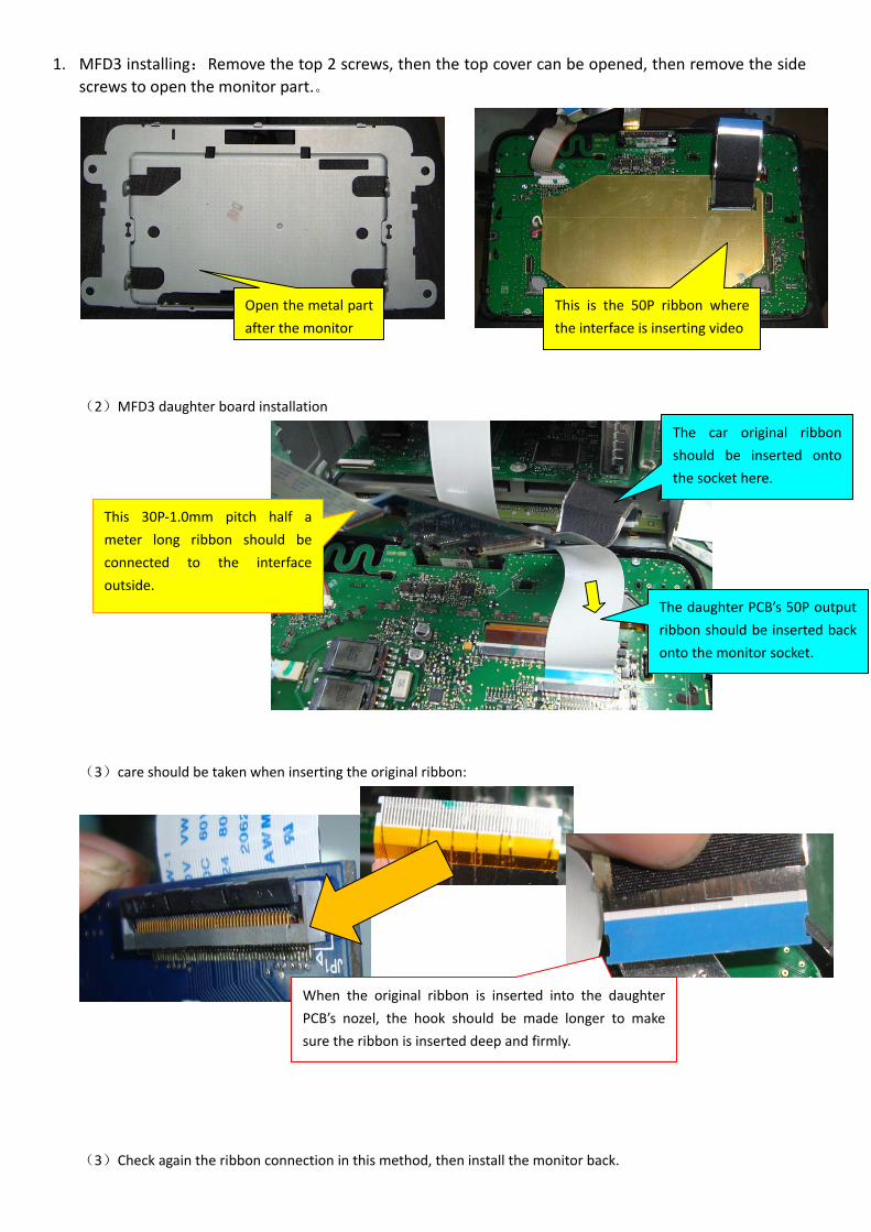
1. MFD3 installing:Remove the top 2 screws, then the top cover can be opened, then remove the side screws to open the monitor part.。
(2)MFD3 daughter board installation
(3)care should be taken when inserting the original ribbon:
(3)Check again the ribbon connection in this method, then install the monitor back.
This 30P‐1.0mm pitch half a
meter long ribbon should be
connected to the interface
outside.
Open the metal part
after the monitor
This is the 50P ribbon where
the interface is inserting video
The daughter PCB’s 50P output
ribbon should be inserted back
onto the monitor socket.
When the original ribbon is inserted into the daughter
PCB’s nozel, the hook should be made longer to make
sure the ribbon is inserted deep and firmly.
The car original ribbon
should be inserted onto
the socket here.
Note: 1. MFD3 interface’s headrest monitor will show image for 15 seconds when powering up, afterward, it turns off
automatically, the user need to long press the keypad to turn it on. 2. The 18~38 Pin inside the ribbon are carrying RGB data. This is where the video is decoded out and inserted
back, and the other pins are direct connected from input to output, that is why we can measure in the above
way to confirm the connection.
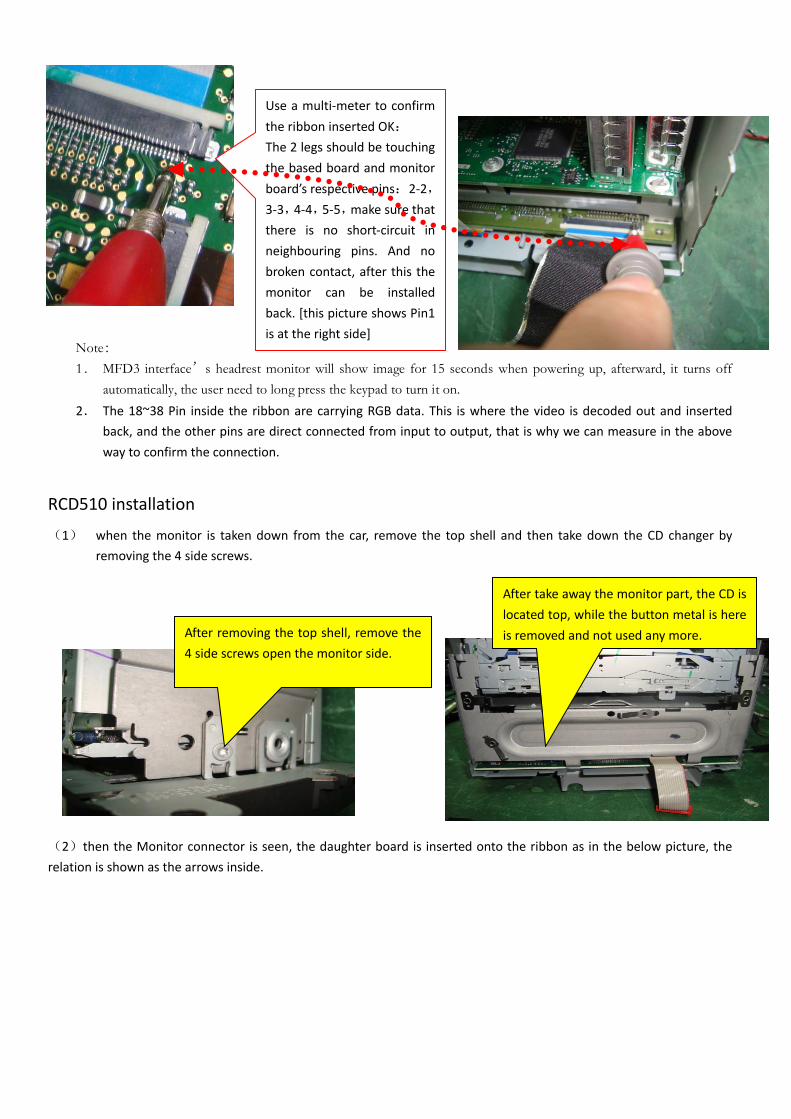
RCD510 installation
(1) when the monitor is taken down from the car, remove the top shell and then take down the CD changer by
removing the 4 side screws.
(2)then the Monitor connector is seen, the daughter board is inserted onto the ribbon as in the below picture, the
relation is shown as the arrows inside.
After removing the top shell, remove the
4 side screws open the monitor side.
After take away the monitor part, the CD is
located top, while the button metal is here
is removed and not used any more.
Use a multi‐meter to confirm
the ribbon inserted OK:
The 2 legs should be touching
the based board and monitor
board’s respective pins:2‐2,
3‐3,4‐4,5‐5,make sure that
there is no short‐circuit in
neighbouring pins. And no
broken contact, after this the
monitor can be installed
back. [this picture shows Pin1
is at the right side]
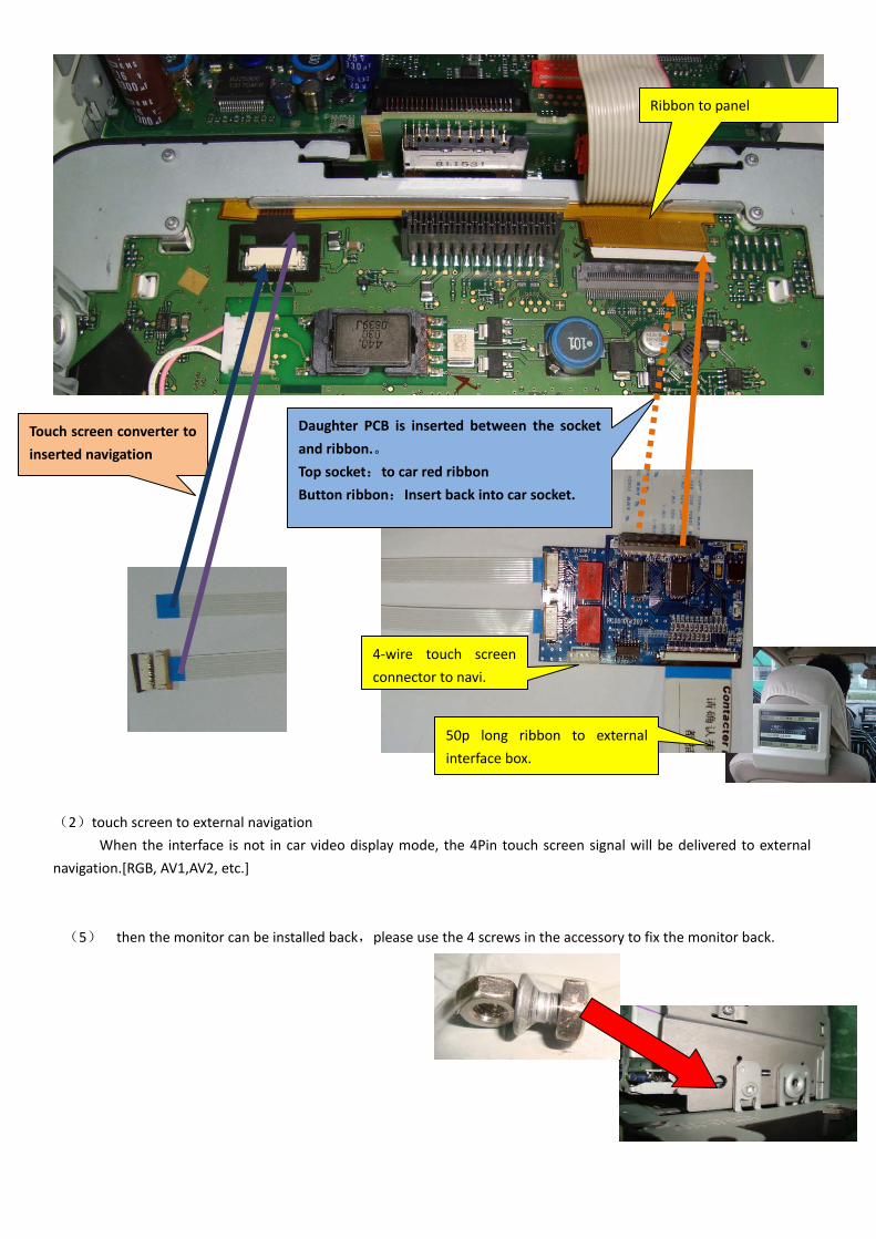
(2)touch screen to external navigation
When the interface is not in car video display mode, the 4Pin touch screen signal will be delivered to external
navigation.[RGB, AV1,AV2, etc.]
(5) then the monitor can be installed back,please use the 4 screws in the accessory to fix the monitor back.
Ribbon to panel
Daughter PCB is inserted between the socket
and ribbon.。
Top socket:to car red ribbon
Button ribbon:Insert back into car socket.
50p long ribbon to external
interface box.
4‐wire touch screen
connector to navi.
Touch screen converter to
inserted navigation