interactive glossy reflections using gpu-based …jye/lab_research/08/pg08.pdfx. yu & r. wang...
TRANSCRIPT
Pacific Graphics 2008T. Igarashi, N. Max, and F. Sillion(Guest Editors)
Volume 27 (2008), Number 7
Interactive Glossy Reflections using GPU-based Ray Tracingwith Adaptive LOD
Xuan Yu1 and Rui Wang2 and Jingyi Yu1
1University of Delaware2University of Massachusetts Amherst
Abstract
We present an interactive GPU-based algorithm for accurately rendering high-quality, dynamic glossy reflectioneffects from both HDR environment maps and local scene objects. Our method uses hardware rasterization to pro-duce primary pixels, and GPU-based BRDF importance sampling [CK07] to quickly generate reflected rays. Weutilize a fast GPU ray tracer proposed by Carr et al. [CHCH06] to compute reflection hits. Our main contributionis an adaptive level-of-detail (LOD) control algorithm that greatly improves ray tracing performance during re-flection shading. Specifically, we use the solid angle represented by each reflected ray to adaptively pick the levelof termination in the BVH traversal step during ray tracing. This leads to 2 ∼ 3x speedup over an unmodifiedimplementation of [CHCH06]. Based on the same solid angle measure, we derive a texture filtering formula to re-duce reflection aliasing artifacts, taking advantage of hardware MIP mapping. This extends the filtering algorithmpresented in [CK07] from environment mapping to local scene reflection. Using our algorithm, we demonstrateinteractive rendering rates for several scenes featuring dynamic lighting and material changes, spatially varyingBRDF parameters, and rigid-body object movement.
1. Introduction
Accurate simulation of complex surface reflections plays acentral role in creating photorealistic images. In computergraphics, reflection of lights from surfaces is typically mod-eled by the Bidirectional Reflectance Distribution Function(BRDF) – a 4D function that uniquely captures the appear-ance properties of each different material. Traditionally inreal-time global illumination systems, diffuse or ideal spec-ular (mirror) materials are assumed because these are twospecial cases of the BRDF that simplify the computation ofreflections. General glossy BRDFs are much more expensiveto simulate, as they require integrating many reflected raysover the hemisphere of incoming light. The importance ofeach reflected ray is determined by the BRDF, and is furtherdependent on the viewing angle, making it very difficult tocache and reuse previously computed samples.
Assuming distant lighting environment, researchers havestudied environment mapping techniques that render accu-rate glossy reflections in real-time. These include prefilteredenvironment maps [CON99,HS99,KVHS00], spherical har-
monics or wavelet basis projection [RH02, WNLH06], andGPU-based BRDF importance sampling [CK07]. The fun-damental limitation of environment mapping is that globalillumination effects such as cast-shadows and indirect light-ing are ignored. Recently, Precomputed Radiance Transfer(PRT) [SKS02, IDYN07, SZC∗07, AUW07] has been shownto enable real-time lighting effects that include local scenereflection, global and self-shadowing, and dynamic BRDFs.These methods typically require fixing scene models so thatthey can make use of precomputed data to amortize shadingcosts on the fly.
Our goal in this paper is to design a fast GPU-based al-gorithm for simulating dynamic glossy reflection effects inreal-time. To allow for general BRDFs and dynamic scenes,we make use of a GPU-based ray tracer to shade reflec-tion rays directly on the fly, without requiring hefty precom-puted data. Recent progress in GPU-based ray tracing hasmade it possible to trace tens of millions of rays in one sec-ond [PBMH02, HSHH07], and there has been an increasinginterest in utilizing such algorithms for computing distribu-tion ray tracing effects such as glossy reflections. The major
c© 2008 The Author(s)Journal compilation c© 2008 The Eurographics Association and Blackwell Publishing Ltd.Published by Blackwell Publishing, 9600 Garsington Road, Oxford OX4 2DQ, UK and350 Main Street, Malden, MA 02148, USA.
X. Yu & R. Wang & J. Yu / Interactive Glossy Reflections using GPU-based Ray Tracing with Adaptive LOD
challenge with current methods is that they rely on coherentbundled rays to exploit the GPU’s massive parallel compu-tation power; however, the initial coherence is likely to belost upon glossy reflection, where the rays diverge from eachother as they travel away from the origin.
As our main contributions, we present an algorithm thatcombines adaptive LOD control with hardware texture fil-tering to avoid shooting excessive rays, reducing the over-all computation cost. We first use hardware rasterization toproduce primary pixels, and GPU-based BRDF importancesampling [CK07] to generate reflected rays. We then utilizea fast GPU ray tracer presented by Carr et al. [CHCH06]to compute reflection hits. During ray tracing, we make useof the solid angle represented by each reflected ray to adap-tively pick the level of termination in the BVH traversal hi-erarchy. This approach in general leads to 2 ∼ 3x speedupover an unmodified implementation of [CHCH06]. Basedon the same solid angle measure, we also derive a texturefiltering formula to efficiently reduce reflection aliasing ar-tifacts, taking advantage of standard hardware MIP map-ping. This method can be seen as an extension of [CK07]from environment mapping to local scene reflections. Usingour algorithm, we demonstrate several scene models featur-ing dynamic lighting and material changes, spatially varyingBRDF parameters, and rigid-body object movement.
Currently, our particular ray tracing implementation lim-its us to models represented by geometry images. It is pos-sible, however, to extend the work to more general repre-sentations, which requires providing a reasonable estimateof the solid angle and an approximate intersection geometryat each node in the ray tracing hierarchy (acceleration struc-ture). We would like to explore these options in future work.
2. Related Work
Real-time Glossy Reflections In recent years, image-basedlighting, which represents natural illumination by distantHDR environment maps [DM97], has been widely used forgenerating convincing shading effects. Under the assump-tion of distant lighting, the expensive cost of computingglossy reflections can be amortized by prefiltering envi-ronment maps [CON99, HS99, KVHS00], or using projec-tion basis such as spherical harmonics or wavelets [RH02,WNLH06]. These methods require preprocessing of BRDFsand thus are not suitable for arbitrary BRDFs dynamicallyapplied in real-time. In addition, they ignore global illumi-nation effects such as cast-shadows and interreflections.
Recently Colbert et al. [CK07] presented GPU-basedBRDF importance sampling to compute real-time, dynamicglossy reflections with minimal requirement imposed on theBRDF. They make use of mipmap filtering to reduce aliasingartifacts caused by low sample count. Similar to environmentmapping, this method only works for local illumination ef-fects, ignoring shadows and interreflections. Our approach
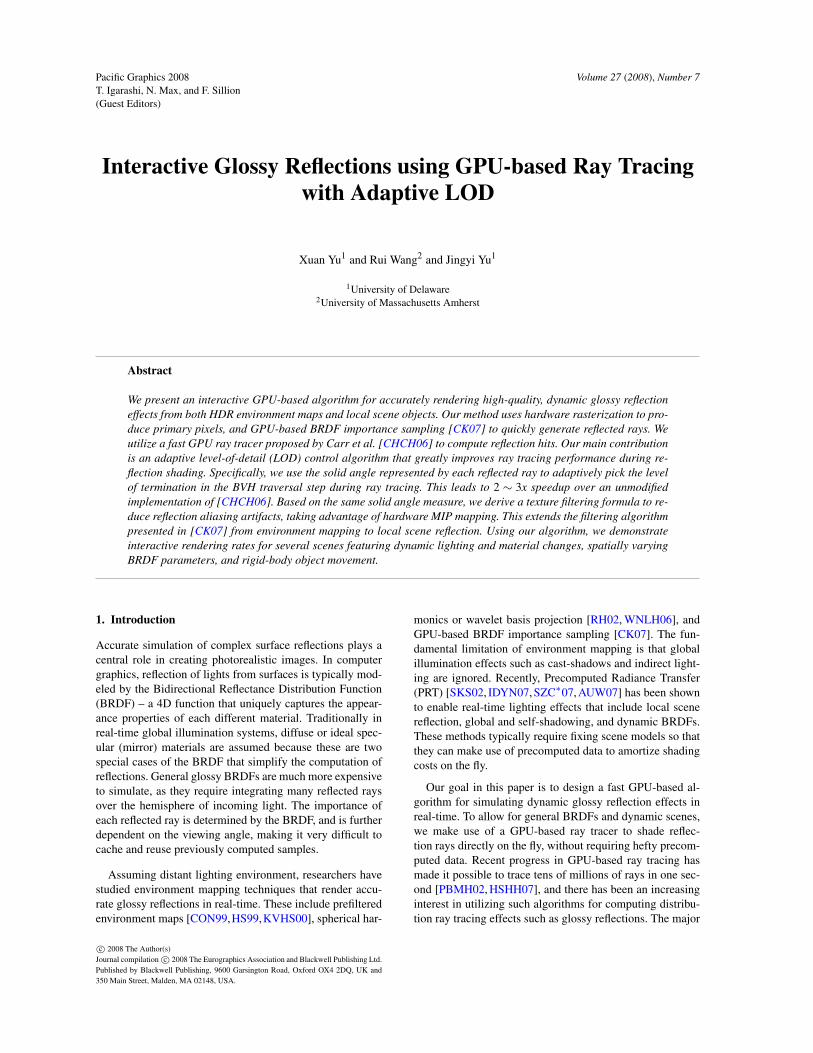
Figure 1: A glossy teapot rendered with spatially varyingBRDFs: the intensity of the "PG 08" texture is used to mod-ulate the specularity of a Phong BRDF. This example runs at5 fps with 512×512 resolution on NVidia 8800 GTX.
extends their work to global effects by utilizing a fast GPUray tracer. We improve the ray tracing performance for re-flected rays by using adaptive LOD control; in addition, weextend their mipmap filtering algorithm from distant envi-ronment maps to textured, local scene objects.
Precomputed Radiance Transfer (PRT) [SKS02, IDYN07,SZC∗07,AUW07] has been shown to enable real-time realis-tic lighting effects that include local scene reflections, globaland self-shadowing, and dynamic BRDFs. These methodsrely on a large amount of precomputed data sampled fromfixed scene models, disabling dynamic object movementor deformation. In general, he precomputation requirementmakes them inflexible at handling arbitrary and per-pixelshading effects, such as BRDFs with broad frequency scales,bump mapped normals, and spatially varying BRDF param-eters. By using real-time ray tracing, our approach permitsgreat flexibility in handling arbitrary reflections. Further-more, it eliminates the need for heavy precomputation: werequire only a small amount of precomputed data (i.e. theBVH structure for ray tracing), which can be quickly up-dated on the fly to allow for deformable scenes [CHCH06].
Real-time Ray Tracing By carefully exploiting the coher-ence of rays, real-time ray tracing has been shown possibleon commodity CPUs [WBWS01,RSH05,DHW∗]. Recently,ray tracing on programmable GPUs has also received signif-icant attention. Purcell et al. [PBMH02] designed a GPU raytracer using a uniform grid acceleration structure. Foley etal. [FS05] proposed an improved algorithm using kd-tree,which is later extended by Horn et al. [HSHH07] with sev-eral major enhancements. Carr et al. [CHCH06] use a bound-ing volume hierarchy (BVH) and a fixed-order traversal al-gorithm to create a ray tracer suitable for geometry imagemodels [GGH02]. This method allows the GPU to efficientlystream through the BVH nodes without maintaining a stack,a major challenge in GPU ray tracing. In addition, the struc-ture of the BVH is simple enough to be updated online, per-mitting dynamic deformable objects.
It is possible nowadays to trace tens of millions of rays per
c© 2008 The Author(s)Journal compilation c© 2008 The Eurographics Association and Blackwell Publishing Ltd.

X. Yu & R. Wang & J. Yu / Interactive Glossy Reflections using GPU-based Ray Tracing with Adaptive LOD
second for primary and shadow rays, thanks to the excellentcoherence of these rays, which can be successfully exploitedby the massive parallel computation power of modern GPUs.This kind of speed is sufficient for interactive applicationsthat require only OpenGL style shading. For distribution raytracing, however, the coherence of reflected rays is usuallyquite poor, as they diverge strongly from each other uponreflection. In addition, multiple rays must be evaluated torobustly estimate the integral of lighting with BRDFs. As aresult, the ray tracing performance slows down significantlywhen glossy interreflections are enabled.
LODs for Ray Tracing Level-of-details (LODs) has beenwidely used for accelerating rendering with large polygonsets [LWC∗02], especially in rasterization-based graphics.Its use in ray tracing, on the other hand, is relatively new.Christensen et al. [CLF∗03] introduced an LOD approachthat combines ray differentials [Ige99] with multiresolutioncaching for offline rendering. Their method supports 3 dis-crete resolution levels. Djeu et al. [DHW∗] presented Razor– a ray tracing architecture that supports watertight multires-olution geometry using a continuous interpolation schemeand a dynamic kd-tree built on-demand. Due to their com-plexity, these methods are only suitable for CPU implemen-tation. Yoon et al. [YLM06] introduced R-LOD – a simpleand fast LOD representation that is designed to dramaticallysimplify massive models and improve ray tracing speed. Ourapproach is fundamentally similar to theirs. The differenceis that we make use of the existing hierarchy of geometryimage models [GGH02, SWG∗03] to simplify the represen-tation of LOD, making it suitable for GPU computing. Thisidea was previously explore by [HR06] and [JJ05] in ras-terization based rendering. In addition, we focus on glossyreflections, and combine LOD with fast, hardware texturefiltering to further reduce computation.
3. Algorithms and Implementation
3.1. Overview and Assumptions
According to the rendering equation [Kaj86], the reflectedradiance from viewing direction ωo at a surface point x dueto incident lighting L is computed by:
B(x,ωo) =∫
Ω
L(x,ω) fr(ωi,ωo) cosθdωi (1)
where ωi is the incident direction, θ is the incident angle, andfr is the BRDF. The incident lighting includes illuminationfrom both distant and near-field sources in the scene. Fornear-field sources, we can rewrite the equation by integratingover the surface area of unoccluded source patches:
B(x,ωo) =∫
AL(xi) fr(xi→ x,ωo)
cosθi cosθo
|xi− x|2dA(xi) (2)
where xi is a point on the patch being reflected (i.e. an in-direct light source). When the patch is far away or smallenough, the BRDF and geometry factors can be treated as
Figure 2: An intersection point and the ray’s cross section.
constant within the patch. In that case, the equation can beapproximated by (see Figure 2):
B(x,ωo)≈ L(xi) fr(xi→ x,ωo)cosθi cosθo
|xi− x|2A(xi) (3)
where xi is a single sample point (in our case, the ray tracingintersection point), L is the average (blurred) radiance acrossthe patch, and A is the total area of the patch (in our case, thecross section area at the point of intersection).
Assumptions We make two assumptions to approximatethe rendering equation and reduce the required computation.First, we classify a scene model as either a diffuse or a glossyobject, and we compute only one bounce of reflection fromthe diffuse objects (plus environment) to the glossy objects.Transfer paths that start from glossy objects are ignored dueto the difficulty in storing a large amount of view-dependentinformation. Second, we assume that the direct lighting ondiffuse objects can be computed quickly at run-time, by us-ing a shadow mapper or prefiltered environment maps. Thisassumption allows us to quickly obtain the diffuse radianceof the reflected objects without having to trace rays further.
Our rendering algorithm consists of three key compo-nents: BRDF importance sampling, LOD-based ray tracing,and image space texture filtering. We have implemented theentire pipeline on the GPU. In the following we describeeach component in detail.
3.2. BRDF Importance Sampling
To simulate Eq. 2, we use BRDF importance sampling,where samples are drawn from a normalized distributionfunction that is closely correlated to the BRDF itself. Mostcommonly used BRDFs have efficient importance samplingfunctions; in particular, diffuse and Phong BRDFs have an-alytic integrals and therefore can be perfectly sampled.
For simplicity, we use the Phong model throughout thepaper. In this case, the importance sampling function p issimply the normalized Phong BRDF:
p(θ,φ) =(n+1)
2 ·π · (cosθ)n (4)
c© 2008 The Author(s)Journal compilation c© 2008 The Eurographics Association and Blackwell Publishing Ltd.
X. Yu & R. Wang & J. Yu / Interactive Glossy Reflections using GPU-based Ray Tracing with Adaptive LOD
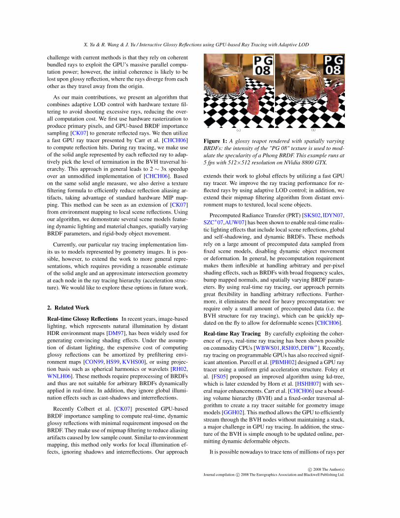
Figure 3: A diagram showing the pipeline of our rendering algorithm.
Here n is the Phong exponent parameter, θ and φ are thetwo spherical angles used to define a direction. This direc-tion is described in the coordinate frame centered aroundthe principle reflection direction ~R = reflect(ωi,~N). The con-stant (n+1)
2·π is a normalization factor. Once a sample directionis chosen, a ray can then be constructed that originates fromx and points toward the sampled direction (θ,φ). Althoughwe choose the Phong model in our implementation, morecomplicated BRDFs can be incorporated as long as their im-portance sampling functions are known.
Solid Angle Similar to [CK07], we assign each sampled raya solid angle representing its angular width:
Ωs =1
N · p(θ,φ)(5)
where N is the total number of samples. According to thisdefinition, the solid angle of a ray is inversely proportionalto the sampling density (importance). This is intuitively cor-rect, as directions that are sampled more frequently shouldrepresent smaller solid angles. The expected value of Ωsshould be 4π
N , which can be easily verified.
3.3. Adaptive LOD for Ray Tracing
We use a GPU ray tracer described in [CHCH06] to tracesampled reflection rays into the scene. This implementationrequires the intersecting geometry to be represented by ge-ometry images [GGH02]. The structure of a geometry imagemakes it very easy to build a Bounding Volume Hierarchy(BVH), which is used as an acceleration structure for raytracing. Specifically, each node of the BVH stores an axis-aligned bounding box of the triangles belonging to that node,and the entire BVH can be easily built using recursive 4-to-1
reduction, similar to the construction of a Mipmap. A fixed-order traversal of the BVH is built ahead of time, permittingthe GPU ray tracer to quickly stream through the structureonline without using a stack.
To improve the ray tracing performance, we use a dy-namic LOD control algorithm. Assume that each reflectedray has a ’cone’ shape that starts at the ray origin (see Fig-ure 2): whenever an intersection point is found, the radiancereturned by the ray should be averaged (blurred) across alarge area in object space. As the ray travels farther away, thecross section of the cone becomes bigger. In this case, pre-cise intersection tests are no longer necessary, since the per-ceptual error caused by inaccurate intersection will be low-pass filtered and become less noticeable. Therefore, we canuse progressively coarser geometry LODs to compute theintersection. In addition, the average radiance value aroundthe intersection point can be efficiently estimated by usinghardware texture filtering.
Our LOD-based ray tracing is implemented by using asimple algorithm to determine the level of termination whentraversing rays through the BVH. As explained before, eachnode of the BVH stores a bounding box; as we traverse aray through the BVH, we chec the solid angle subtended bythe bounding box of the current node, and compare it withthe solid angle represented by the ray. The solid angle of abounding box can be approximated by:
ΩBBox = π|pmax− pmin|2
4 |(pmax + pmin)/2− x|2(6)
where pmax and pmin are the two corner points of the bound-ing box. We compare this value with Ωs – the solid anglerepresented by the current ray. When ΩBBox > Ωs, the in-tersection test has to be more precise, therefore we keep
c© 2008 The Author(s)Journal compilation c© 2008 The Eurographics Association and Blackwell Publishing Ltd.

X. Yu & R. Wang & J. Yu / Interactive Glossy Reflections using GPU-based Ray Tracing with Adaptive LOD
traversing the BVH without any change. On the other hand,if ΩBBox ≤ Ωs, it indicates that the geometry to be inter-sected with is already smaller than the angular width of theray. Since the radiance values within the solid angle have tobe averaged, this suggests that a more precise intersectionis not necessary. In this case, instead of further tracing thechildren nodes, we can stop at the current node, treating itas a leaf node, and using its approximate geometry directlyto compute intersection. If an intersection is found, the av-erage radiance of the ray will then be retrieved using texturefiltering explained in the next step.
One drawback of this approach is that when the number ofsamples is insufficient, the solid angle represented by eachray will be quite large. In this case, many of the rays willbe intersecting at very coarse levels of the LOD, resultingin noticeable aliasing artifacts. Overall this problem shouldbe addressed by increasing the number of samples. However,we do note that due to importance sampling, rays with higherimportance are associated with smaller solid angles, forcingthem to intersect with finer LOD levels. Therefore this prop-erty helps to solve the problem partly by providing higheraccuracy for important rays.
We found through experiments that Eq 5 often under-estimates the solid angle of important rays, resulting invery small values, especially when the BRDF is very sharp.Therefore, instead of directly comparing ΩBBox with Ωs, weadd a scaling factor α
2 to Ωs, which provides a more flexiblecontrol on how the adaptive LOD criteria is applied. Hencein practice, we use the following comparison:
ΩBBox ≤ α2 ·Ωs (7)
Experiments suggest that an α value between [1,10] pro-duces good results. Adjusting this parameter provides atradeoff between performance and intersection accuracy.Note that a very small α value is equivalent to disabling theadaptive LOD control, forcing the ray tracer to perform fullintersection tests. When α = 0, the algorithm falls back tothe original implementation by [CHCH06].
3.4. Texture Filtering
When an intersection is found, we compute its cross sec-tion in object space, and use this information to guide tex-ture filtering in order to estimate the average diffuse radiancewithin the cross section. In general the intersection cross sec-tion may have an arbitrary shape, making it very difficult toperform an accurate estimation. In practice, however, we canassume the cross section is locally flat, thus can be estimatedfrom the solid angle of the ray:
A(xi)≈|xi− x|2 ·Ωs
cosθi(8)
This is approximately equal to the cross section resultingfrom intersecting a ray cone with the tangent plane at thepoint xi. See Figure 2 for an illustration.
With the estimated intersection area, we can then evalu-ate the appropriate Mipmap level for computing the aver-age radiance. The general idea is that the area A(xi) cov-ers a certain number of pixels in the texture space, thereforewe would like to pick a Mipmap level that roughly corre-sponds to that number of pixels. To do so, we assume thatthe texture coordinates in the local neighborhood of xi isuniform. This assumption is reasonable since the geometryimage construction algorithm guarantees uniformity up to amaximum distortion factor. Next, we estimate the Mipmaplevel as:
l =12
log2
(A(xi)Apixel
)=
12
(log2 A(xi)− log2 Apixel
)(9)
where Apixel is a measure called area per pixel – the ob-ject space area covered by one pixel. This is used to con-vert area from object space to texel space. It can be easilycomputed from the geometry image by estimating the areacovered the two triangles spanning one pixel size in geom-etry image space. These values are precomputed and storedtogether with the geometry image.
Note that this LOD formula implicitly assumes that thetexture scale is roughly equal in the u and v directions; inother words, the texture scale is isotropic. If this is not thecase (i.e., the texture is stretched differently along u andv), we can separate the formula for each direction, and useanisotropic filtering to achieve more accurate results.
3.5. Implementation Details
Scene Models As mentioned before, we require that dif-fuse objects in our scenes be represented as geometry im-ages. Glossy objects do not participate in intersection tests,therefore do not need to have geometry image representa-tions. Note that self-reflections are not supported on glossyobjects, although it would be easy to modify the algorithmso that a glossy object can reflect the diffuse portion of itself.
We generate the BVH and fixed traversal order offline foreach geometry image model, by following the algorithm pre-sented in [CHCH06]. In addition, we precompute Apixel – thearea per pixel measure for each texel, and store it in the al-pha channel of the geometry image textures. Figure 3 showsa diagram of our rendering algorithm.
BVH for Ray Tracing The construction of the BVH forgeometry images is very similar to constructing a Mipmap,which uses a simple 4-to-1 reduction algorithm in bottom-up fashion. At each node, the axis-aligned bounding box isaggregated from its four children node; and the two cornerspmin and pmax of the bounding box are stored in a texture.
Following this step, we build a fixed-order traversal link asin [CHCH06]. Specifically, a hit map and miss map are con-structed which indicate where the ray should go when it hitsor misses the current node. When traversing a ray throughthe BVH, it is tested against the bounding box at each node.
c© 2008 The Author(s)Journal compilation c© 2008 The Eurographics Association and Blackwell Publishing Ltd.
X. Yu & R. Wang & J. Yu / Interactive Glossy Reflections using GPU-based Ray Tracing with Adaptive LOD
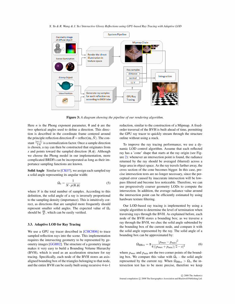
Figure 4: Comparing the rendering results with and withouttexture filtering. Note the differences in aliasing artifacts.
If the ray hits the volume, it will follow the traversal orderto the next node in the sequence, until it reaches a leaf node,where the ray will be tested against the actual triangles. If,on the other hand, the ray misses the current node, then thenext node to visit is indicated by the miss map.
Geometry Image LODs Geometry images impose natu-ral LOD structures. At each node in the BVH, we simplytake the reduced pixels to form an approximated geometryat that level. For example, if the original geometry imageis at 512× 512 resolution, then the finest level LOD has512×512×2 triangles, and the next level has 256×256×2triangles, by skipping every other pixel in the rows andcolumns of the geometry image. The level following that has128×128×2 triangles, and so on. Each level reduces the tri-angle count by 4. The approximate geometry is used for raytracing whenever the LOD criteria is met.
Rendering Diffuse Objects The first step in our render-ing algorithm is to shade diffuse objects. This can be doneby shadow mapping for small light sources. As we focusmore on environment lighting, it is actually non-trivial tocompute accurate, shadowed direct illumination in real-time.To produce convincing shading effects, we make use of un-shadowed, prefiltered environment maps such as [RH01],and combine them with ambient occlusion maps to produceglobal shadowing effects. Ideally we could also use our raytracer to keep tracing rays upon secondary reflections, butthis would significantly increase the computation costs. Atrun-time, we compute and store the radiance of diffuse ob-jects together with their geometry image. This allows us toquickly obtain the direct lighting value from diffuse objectswithout the need for further ray tracing. Note that this isanalogous to use caching schemes, such as irradiance cache,to reduce the computation cost of global illumination.
To compute the diffuse radiance, we take each geometryimage with its ambient occlusion map as input to a frag-ment shader. We use the surface normal of each geometryimage pixel to index into a prefiltered irradiance environ-ment map and obtain an irradiance value. This value is thenmultiplied with the diffuse reflectance and ambient occlu-sion color, and the result is output to a target texture. The tar-
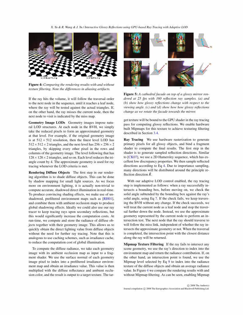
Figure 5: A cathedral facade on top of a glossy mirror ren-dered at 25 fps with 160 reflection ray samples. (a) and(b) show how glossy reflections change with respect to theviewing angle. (c) and (d) show how how glossy reflectionschange as we rotate the facade towards the mirror.
get texture will be bound to the GPU shader in the ray tracingpass for computing glossy reflections. We enable hardwarebuilt Mipmaps for this texture to achieve texturing filteringdescribed in Section 3.4.
Ray Tracing We use hardware rasterization to generateprimary pixels for all glossy objects, and bind a fragmentshader to compute the final results. The first step in theshader is to generate sampled reflection directions. Similarto [CK07], we use a 2D Hamersley sequence, which has ex-cellent low discrepancy properties. We then sample reflecteddirections according to Eq 4. Due to importance sampling,many directions will be distributed around the principle re-flection direction ~R.
With our adaptive LOD control enabled, the ray tracingstep is implemented as follows: when a ray successfully in-tersects a bounding box, before moving on, we check thesolid angle subtended by the bounding box against the ray’ssolid angle, using Eq 7. If the check fails, we keep travers-ing the BVH without any change. If the check succeeds, wewill treat the current node as a leaf node and stop the traver-sal further down the node. Instead, we use the approximategeometry represented by the current node to perform an in-tersection test. The next node that the ray should traverse towill follow the miss link, independent of whether the ray in-tersects the approximate geometry or not. When the traversalis completed, the intersection point with the closest distancealong the ray will be returned.
Mipmap Texture Filtering If the ray fails to intersect anyscene geometry, we use the ray’s direction to index into theenvironment map and return the radiance contribution. If, onthe other hand, an intersection point is found, we use theMipmap level selected by Eq 9 to index into the radiancetexture of the diffuse objects and obtain an average radiancevalue. In Figure 4 we compare the rendering results with andwithout Mipmap filtering. As can be seen, enabling Mipmap
c© 2008 The Author(s)Journal compilation c© 2008 The Eurographics Association and Blackwell Publishing Ltd.

X. Yu & R. Wang & J. Yu / Interactive Glossy Reflections using GPU-based Ray Tracing with Adaptive LOD
Figure 6: A glossy teapot reflecting several diffuse objects rendered at 3.45 fps. Note the change in glossy reflections as wemove the teapot around the scene.
Adjust Number of Samples Adjust LOD Control (α)Scene G.I. Size Triangles 20 40 60 10 3 1Facade N/A N/A 185.11 fps 92.55 fps 45.58 fps N/A N/A N/AGargoyle + teapot 64x64 8K 11.29 fps 5.91 fps 3.76 fps 7.89 fps 6.4 fps 5.91 fpsGargoyle + plane 256x256 128K 6.45 fps 2.91 fps 1.87 fps 6.44 fps 4.23 fps 2.91 fpsComplex 32x32x4(objects) 8K 7.11 fps 3.45 fps 2.29 fps 3.74 fps 3.61 fps 3.45 fps
Figure 7: Performance profiles of our algorithm. From left to right, the columns present the geometry image size, triangle count,rendering frame rates by adjusting the number of samples, and adjusting the LOD control parameter α.
filtering effectively reduces aliasing artifacts and producessmooth rendering results.
4. Results and Discussion
Our algorithm is implemented using DirectX 9.0c withShader Model 3.0. All experiments are recorded on a PCwith 2.13 Ghz Intel Core2 Duo CPU, 2GB memory, and anNVidia 8800 GTX graphics card. Rendering frame rates arereported as the total frame rates at 512×512 image resolu-tion for the entire pipeline. Since the step to shade diffuseobjects is very fast, the rendering cost is dominated by theglossy reflection shading.
Table 7 summarizes the performance data. Our algorithmperforms computation in image-space, therefore the render-ing cost scales linearly with the total number of pixels cov-ered by glossy objects. In addition, adjusting the LOD con-trol parameter α changes the frame rates: lowering α reducesthe effect of LOD control, thus reducing the frame rates aswell. When α is zero, the LOD control is turned off, and thealgorithm falls back to [CHCH06].
Dynamic Glossy Reflection Effects In Figure 5, we show acathedral facade rendered on top of a glossy mirror that has aPhong BRDF with n = 1000. We sample 160 rays per pixel,and the scene is rendered at 25 fps. Note that the blurrinessof the reflections changes in accordance with the relative dis-tance between the two objects. It also changes as the viewingdirection moves towards the grazing angle, as shown in Fig-
ure 5 (a) and (b). As the object is moved closer to the mirror,the reflections become sharper as show in (c) and (d).
We allow the users to dynamically change the BRDF pa-rameters at run-time. In Figure 8 (a)-(c), we render the re-flections of a gargoyle model on a glossy teapot with chang-ing Phong exponent parameter n. The gargoyle model isa 64×64 geometry. We sample 40 rays per pixel and useα = 1 for the LOD control. This scene is rendered at 5.91fps at 512×512 resolution. In Figure 8 (d)-(f), we graduallymove the gargoyle model away from the teapot, and observethe change in reflection blurriness. In Figure 6, we show amore complex scene with multiple diffuse objects, each rep-resented by a 32×32 geometry image. This scene is renderedat 3.45 fps.
We can also render various per-pixel shading effects suchas spatially varying BRDF parameters modulated by a tex-ture map on the fly. In Figure 1, the intensity value of a "PG08" texture map is used to modulate the Phong exponent pa-rameter n. Note the per-pixel reflection effects. The texturesapplied in the two images are inverted, therefore in (a) thearea covered by the sign is more specular while in (b) it ismore blurry. Since we compute the BRDF sampling on thefly, we can manipulate the spatially varying BRDF parame-ters in real-time at no additional cost. Complex BRDFs canalso be incorporated as long as their importance samplingfunctions are known.
Aliasing Artifacts When the number of sample rays is in-sufficient, the glossy reflections are subject to aliasing arti-
c© 2008 The Author(s)Journal compilation c© 2008 The Eurographics Association and Blackwell Publishing Ltd.

X. Yu & R. Wang & J. Yu / Interactive Glossy Reflections using GPU-based Ray Tracing with Adaptive LOD
Figure 8: This gargoyle model reflected on a glossy teapot is rendered at 5.97 fps. In (a)-(c), we dynamically change thesharpness of the BRDF applied on the teapot; in (d)-(f), we move the gargoyle model farther away from the teapot. Note thechange of blurriness in the reflected images.
Res. LOD off α = 1 α = 3 α = 10 Speedup1024 2.45 3.04 3.98 5.37 2.2512 2.86 3.5 4.81 6.55 2.3256 3.61 4.04 5.92 8.6 2.4128 4.33 4.55 6.03 8.63 2.064 6.16 5.92 6.6 8.72 -32 8.55 7.99 8.21 9.26 -
Figure 9: A comparison of rendering fps (gargoyle + planewith 30 samples) by varying the geometry image size as wellas the LOD control parameter α. Our algorithm achieves2∼3 times speedup over [CHCH06]. By applying adaptiveLOD control, the decrease in rendering performance is lesssensitive to the increase in geometry image size.
facts. In this case, our Mipmap based texture filtering (Sec-tion 3.4) is effective at reducing the aliasing artifacts. Fig-ure 4 provides a comparison by turning on and off texturefiltering. Observe the differences in the rendered results.
The aliasing artifacts are more severe near the silhouetteson the reflected images, where the ray cone partially inter-sects with the foreground and partially with the backgroundenvironment. In this case, the texture filtering alone does not
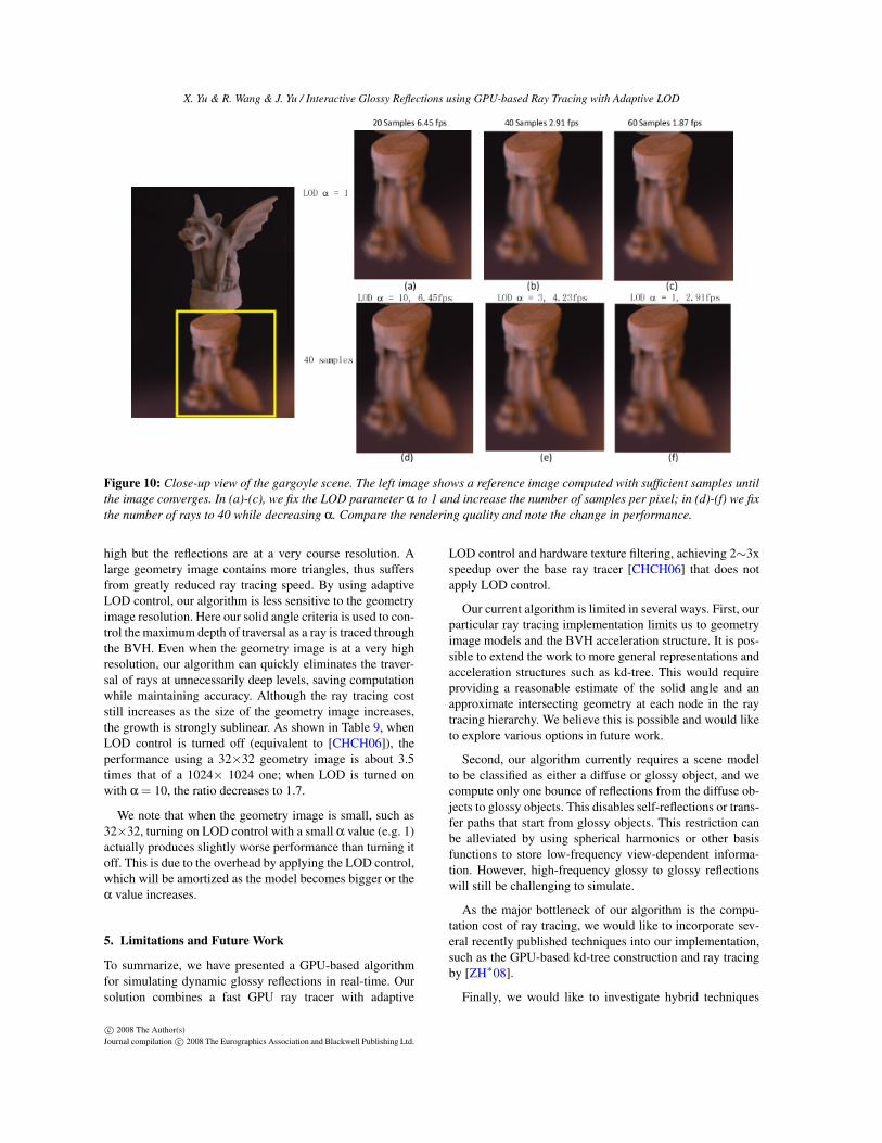
help much, and we need to increase the ray samples to im-prove the accuracy. Figure 10 (a)-(c) provide a comparisonby changing the number of sampled rays. Note as we usemore samples, the rendered image gradually converges tothe reference image shown on the left of the figure; at thesame time, the performance decreases linearly to the num-ber of samples, which is expected.
Adaptive LOD control By applying our adaptive LODcontrol, we can achieve 2∼ 3x speedup in rendering perfor-mance while maintaining high rendering quality. The LODcontrol allows early termination of rays to reduce ray tracingcost. Figure 10 (d)-(f) provides a set of experiments. Usinga larger α value, we can avoid tracing excessive rays andimprove the frame rates. While this makes the intersectiontests less accurate, the rendering quality is still quite highcompared to the reference. Our parameters are typically setas follows: when the Phong BRDF is very sharp (n > 3000),we use 20 rays per pixel and set α = 3; otherwise we use 40rays and set α = 10.
In [CHCH06], the geometry image resolution is a key fac-tor affecting the ray tracing performance. A small geometryimage contains less triangles, thus the ray tracing speed is
c© 2008 The Author(s)Journal compilation c© 2008 The Eurographics Association and Blackwell Publishing Ltd.
X. Yu & R. Wang & J. Yu / Interactive Glossy Reflections using GPU-based Ray Tracing with Adaptive LOD
Figure 10: Close-up view of the gargoyle scene. The left image shows a reference image computed with sufficient samples untilthe image converges. In (a)-(c), we fix the LOD parameter α to 1 and increase the number of samples per pixel; in (d)-(f) we fixthe number of rays to 40 while decreasing α. Compare the rendering quality and note the change in performance.
high but the reflections are at a very course resolution. Alarge geometry image contains more triangles, thus suffersfrom greatly reduced ray tracing speed. By using adaptiveLOD control, our algorithm is less sensitive to the geometryimage resolution. Here our solid angle criteria is used to con-trol the maximum depth of traversal as a ray is traced throughthe BVH. Even when the geometry image is at a very highresolution, our algorithm can quickly eliminates the traver-sal of rays at unnecessarily deep levels, saving computationwhile maintaining accuracy. Although the ray tracing coststill increases as the size of the geometry image increases,the growth is strongly sublinear. As shown in Table 9, whenLOD control is turned off (equivalent to [CHCH06]), theperformance using a 32×32 geometry image is about 3.5times that of a 1024× 1024 one; when LOD is turned onwith α = 10, the ratio decreases to 1.7.
We note that when the geometry image is small, such as32×32, turning on LOD control with a small α value (e.g. 1)actually produces slightly worse performance than turning itoff. This is due to the overhead by applying the LOD control,which will be amortized as the model becomes bigger or theα value increases.
5. Limitations and Future Work
To summarize, we have presented a GPU-based algorithmfor simulating dynamic glossy reflections in real-time. Oursolution combines a fast GPU ray tracer with adaptive
LOD control and hardware texture filtering, achieving 2∼3xspeedup over the base ray tracer [CHCH06] that does notapply LOD control.
Our current algorithm is limited in several ways. First, ourparticular ray tracing implementation limits us to geometryimage models and the BVH acceleration structure. It is pos-sible to extend the work to more general representations andacceleration structures such as kd-tree. This would requireproviding a reasonable estimate of the solid angle and anapproximate intersecting geometry at each node in the raytracing hierarchy. We believe this is possible and would liketo explore various options in future work.
Second, our algorithm currently requires a scene modelto be classified as either a diffuse or glossy object, and wecompute only one bounce of reflections from the diffuse ob-jects to glossy objects. This disables self-reflections or trans-fer paths that start from glossy objects. This restriction canbe alleviated by using spherical harmonics or other basisfunctions to store low-frequency view-dependent informa-tion. However, high-frequency glossy to glossy reflectionswill still be challenging to simulate.
As the major bottleneck of our algorithm is the compu-tation cost of ray tracing, we would like to incorporate sev-eral recently published techniques into our implementation,such as the GPU-based kd-tree construction and ray tracingby [ZH∗08].
Finally, we would like to investigate hybrid techniques
c© 2008 The Author(s)Journal compilation c© 2008 The Eurographics Association and Blackwell Publishing Ltd.
X. Yu & R. Wang & J. Yu / Interactive Glossy Reflections using GPU-based Ray Tracing with Adaptive LOD
such as combining ray tracing with image-space filtering toaccelerate the computation of glossy reflections further.
Acknowledgements We would like to thank the PG review-ers for their generous comments and suggestions. This workis supported in part by the UMass Faculty Research GrantP1-FRG-0029 and the National Science Foundation undergrant NSF-MSPA-MCS-0625931.
References
[AUW07] AKERLUND O., UNGER M., WANG R.: Precomputedvisibility cuts for interactive relighting with dynamic brdfs. InProceedings of Pacific Graphics (2007), pp. 161–170.
[CHCH06] CARR N. A., HOBEROCK J., CRANE K., HART
J. C.: Fast gpu ray tracing of dynamic meshes using geome-try images. In GI ’06: Proceedings of Graphics Interface 2006(2006), pp. 203–209.
[CK07] COLBERT M., KRIVÁNEK J.: GPU Gems 3. AddisonWesley, 2007, ch. 20. GPU-based Importance Sampling, pp. 459–479.
[CLF∗03] CHRISTENSEN P., LAUR D., FONG J., WOOTEN W.,BATALI D.: Ray differentials and multiresolution geometrycaching for distribution ray tracing in complex scenes. ComputerGraphics Forum 22, 3 (2003), 543–552.
[CON99] CABRAL B., OLANO M., NEMEC P.: Reflection spaceimage based rendering. In Proceedings of SIGGRAPH ’99(1999), pp. 165–170.
[DHW∗] DJEU P., HUNT W., WANG R., ELHASSAN I., STOLL
G., MARK W. R.: Razor: An architecture for dynamic multireso-lution ray tracing. conditionally accepted to ACM Trans. Graph.
[DM97] DEBEVEC P. E., MALIK J.: Recovering high dynamicrange radiance maps from photographs. In Proceedings of SIG-GRAPH ’97 (1997), pp. 369–378.
[FS05] FOLEY T., SUGERMAN J.: Kd-tree acceleration structuresfor a gpu raytracer. In Proceedings of Graphics Hardware ’05(2005), pp. 15–22.
[GGH02] GU X., GORTLER S. J., HOPPE H.: Geometry images.ACM Trans. Graph. 21, 3 (2002), 355–361.
[HR06] HERNÁNDEZ B., RUDOMIN I.: Simple dynamic lod forgeometry images. In Proceedings of GRAPHITE ’06 (2006),pp. 157–163.
[HS99] HEIDRICH W., SEIDEL H.-P.: Realistic, hardware-accelerated shading and lighting. In Proceedings of SIGGRAPH’99 (1999), pp. 171–178.
[HSHH07] HORN D. R., SUGERMAN J., HOUSTON M., HAN-RAHAN P.: Interactive k-d tree gpu raytracing. In Proceedings ofSI3D 2007 (2007), pp. 167–174.
[IDYN07] IWASAKI K., DOBASHI Y., YOSHIMOTO F., NISHITA
T.: Precomputed radiance transfer for dynamic scenes taking intoaccount light interreflection. In Proceedings of the 18th Euro-graphics Symposium on Rendering (2007), pp. 35–44.
[Ige99] IGEHY H.: Tracing ray differentials. In Proceedings ofSIGGRAPH ’99 (1999), pp. 179–186.
[JJ05] JUNFENG JI ENHUA WU S. L. X. L.: Dynamic lod ongpu. In Proceedings of CGI 2005 (2005), pp. 108–114.
[Kaj86] KAJIYA J. T.: The rendering equation. In Proceedings ofSIGGRAPH ’86 (1986), pp. 143–150.
[KVHS00] KAUTZ J., VÁZQUEZ P.-P., HEIDRICH W., SEIDEL
H.-P.: Unified approach to prefiltered environment maps. InProc. of the 11th Eurographics Rendering Workshop (2000),pp. 185–196.
[LWC∗02] LUEBKE D., WATSON B., COHEN J. D., REDDY M.,VARSHNEY A.: Level of Detail for 3D Graphics. Elsevier Sci-ence Inc., 2002.
[PBMH02] PURCELL T., BUCK I., MARK W., HANRAHAN P.:Ray tracing on programmable graphics hardware. ACM Trans.Graph. 21, 3 (2002), 703–712.
[RH01] RAMAMOORTHI R., HANRAHAN P.: An efficient rep-resentation for irradiance environment maps. In Proceedings ofSIGGRAPH ’01 (2001), pp. 497–500.
[RH02] RAMAMOORTHI R., HANRAHAN P.: Frequency spaceenvironment map rendering. ACM Trans. Graph. 21, 3 (2002),517–526.
[RSH05] RESHETOV A., SOUPIKOV A., HURLEY J.: Multi-levelray tracing algorithm. ACM Trans. Graph. 24, 3 (2005), 1176–1185.
[SKS02] SLOAN P.-P., KAUTZ J., SNYDER J.: Precomputedradiance transfer for real-time rendering in dynamic, low-frequency lighting environments. ACM Trans. Graph. 21, 3(2002), 527–536.
[SWG∗03] SANDER P. V., WOOD Z. J., GORTLER S. J., SNY-DER J., HOPPE H.: Multi-chart geometry images. In SGP ’03:Proceedings of the 2003 Eurographics/ACM SIGGRAPH sympo-sium on Geometry processing (2003), pp. 146–155.
[SZC∗07] SUN X., ZHOU K., CHEN Y., LIN S., SHI J., GUO B.:Interactive relighting with dynamic brdfs. ACM Trans. Graph.26, 3 (2007), 27.
[WBWS01] WALD I., BENTHIN C., WAGNER M., SLUSALLEK
P.: Interactive rendering with coherent ray tracing. ComputerGraphics Forum 20, 3 (2001), 153–164.
[WNLH06] WANG R., NG R., LUEBKE D., HUMPHREYS G.:Efficient wavelet rotation for environment map rendering. InProceedings of the 17th Eurographics Symposium on Rendering(2006), pp. 173–182.
[YLM06] YOON S.-E., LAUTERBACH C., MANOCHA D.: R-lods: fast lod-based ray tracing of massive models. Vis. Comput.22, 9 (2006), 772–784.
[ZH∗08] ZHOU K., HOU Q., , WANG R., GUO B.: Real-timekd-tree construction on graphics hardware. Microsoft TechnicalReport, MSR-TR-2008-52 (2008).
c© 2008 The Author(s)Journal compilation c© 2008 The Eurographics Association and Blackwell Publishing Ltd.