intel's mcs-51 family of microcontrollers and its ... · simulates the control and operation...
TRANSCRIPT

TRAFFIC LIGHTS INTERFACE
1
CONTENTS
PAGE NO
1.0 Introduction 2
2.0 Description of the Circuit 2
3.0 Installation 5
4.0 Demonstration Examples 6
4.1 Demonstration Program for MPS 85-3 Trainer 7
4.2 Demonstration Program for ESA 85-2 Trainer 10
4.3 Demonstration Program for ESA-80 Trainer 13
4.4 Demonstration Program for ESA-65 Trainer 16
4.5 Demonstration Program for ESA-68K Trainer 19
4.6 Demonstration Program for ESA 86/88-2 Trainer 21
4.7 Demonstration Program for ESA-31 Trainer 24
4.8 Demonstration Program for ESA-196 Trainer 26
4.9 Demonstration Program for ESA 68K-2 Trainer 29
4.10 Demonstration Program for ESA-51 Trainer 32
4.11 Demonstration Program for ESA 86/88-3 Trainer 34
4.12 Demonstration Program for ESA-51E Trainer 35
4.13 Demonstration Program for ESA 86/88E Trainer 37
Appendix A : Schematic Diagram
Appendix B : Placement Diagram

TRAFFIC LIGHTS INTERFACE
2
TRAFFIC LIGHTS INTERFACE
1.0 INTRODUCTION
Electro Systems Associates Private Limited (ESA) manufactures trainers for most of the popular
microcomputers viz 8085, Z-80, 6502, 8086/8088 and 68000. ESA offers a variety of modules
which can be interfaced to these trainers. These modules can be effectively used for
teaching/training in the laboratories.
The present manual describes one such interface module traffic lights interface. The interface
simulates the control and operation of traffic lights at a junction of four roads. The interface provides
a set of 6 LED indicators at each of the four corners. Each of these LEDs can be controlled by a port
line.
Thus the interface allows the user to simulate a variety of traffic situations using appropriate
software routines. The sample programs provided in section 4 of this manual simulate some
interesting traffic movement sequences.
This interface can be connected to any of ESA trainers viz., MPS 85-3, ESA 85-2, ESA 80, ESA 65,
ESA 68K, ESA 86/88-2, ESA 31, ESA 51, ESA 86/88-3 & ESA 51E.
2.0 DESCRIPTION OF THE CIRCUIT
Please refer to the schematic diagram of this interface presented at the end of this manual. As already
mentioned, the interface provides a set of six LEDs at each of the four corners of a four road junction.
The organization of these LEDs is identical at each of the four corners. Hence, for simplicity, the
organization is described below with reference to the LEDs at SOUTH-WEST corner only.
The LEDs at SOUTH-WEST corner are organized as follows:
RED
A
R S L
DL PEDESTRIANS DL SOUTH

TRAFFIC LIGHTS INTERFACE
3
RED : Referred to as SOUTH RED henceforth
A : Referred to as SOUTH AMBER henceforth
L : Referred to as SOUTH LEFT henceforth
S : Referred to as SOUTH STRAIGHT henceforth
R : Referred to as SOUTH RIGHT henceforth
DL : Referred to as SOUTH PEDESTRIAN henceforth (Please note that DL
refers to a set of two LEDs, one on either side of the road).
Of these , the first five LEDs will be ON or OFF depending on the state of the corresponding port line
(LED is ON if the port line is Logic HIGH and LED is OFF if the port line is Logic LOW). The last
one marked as DL is a set of two dual-colour LEDs and they both will be either RED or GREEN
depending on the state of the corresponding port line (RED if the port line is Logic HIGH and
GREEN if the port line is Logic LOW).
There are four such sets of LEDs and these are controlled by 24 port lines. Each port line is inverted
and buffered using 7406 (open collector inverter buffers) and is used to control an LED. Dual-colour
LEDs are controlled by a port line and its complement.
The 24 LEDs and their corresponding port lines are summarized below
LED Port Line
SOUTH RED PA3
AMBER PA2
LEFT PA0
STRAIGHT PC3
RIGHT PA1
PEDESTRIAN PC6
EAST RED PA7
AMBER PA6
LEFT PA4
STRAIGHT PC2
RIGHT PA5
PEDESTRIAN PC7
NORTH RED PB3
AMBER PB2
LEFT PB0
STRAIGHT PC1
RIGHT PB1
PEDESTRIAN PC4
WEST RED PB7
AMBER PB6
LEFT PB4

TRAFFIC LIGHTS INTERFACE
4
STRAIGHT PC0
RIGHT PB5
PEDESTRIAN PC5
User can assign any meaningful interpretation to these LEDs and then develop software accordingly.
Usually, the interpretation would be as follows:
Vehicles coming from one direction are controlled by the LEDs at the opposite corner.
For example, vehicles coming from NORTH are controlled by the set of LEDs at the SOUTH WEST
corner, as shown below:
Vehicles coming from NORTH can
go left (i.e to EAST) if SOUTH LEFT LED is ON
go right (i.e to WEST) if SOUTH RIGHT LED is ON
go straight (i.e to SOUTH) if SOUTH STRAIGHT LED is ON
Further, the above movements are followed only if SOUTH RED LED is OFF. If SOUTH RED LED
is ON , no movement is allowed for vehicles from north. Pedestrian crossing on SOUTH is allowed
when SOUTH PEDESTRIAN is green and disallowed when it is red. It is obvious that, logically
some combinations can not be allowed. For example, SOUTH RED = OFF, SOUTH STRAIGHT =
ON and SOUTH PEDESTRIAN = GREEN is not allowed (vehicles are allowed to go from NORTH
to SOUTH and pedestrians are allowed to cross on SOUTH). SOUTH AMBER can be ON to indicate
that SOUTH RED is about to change its status from OFF to ON.
The movement of vehicles and pedestrians on the roads can be controlled in a similar way.
As already noted, user can assign a different interpretation if desired. However, the sample programs
presented in the next section are based on the above simple interpretation.
EXAMPLE:
Determine port values for the following traffic situation:
Vehicles from WEST are allowed to go NORTH or EAST.
Vehicles from EAST are allowed to go WEST.
Pedestrian crossing is allowed on SOUTH.
No other vehicle movement /pedestrian crossings are allowed.
Now, as per the above interpretation, the status of the LEDs should be as shown below:
RED AMBER LEFT STRAIGHT RIGHT PEDESTRIAN
SOUTH ON OFF OFF OFF OFF GREEN
EAST OFF OFF ON ON OFF RED
NORTH ON OFF OFF OFF OFF RED
WEST OFF OFF OFF ON OFF RED

TRAFFIC LIGHTS INTERFACE
5
From the correspondence already between the port lines and LEDs, we can now determine the logic
values for each port line. For example, PA0 should be Logic LOW as SOUTH LEFT RED is OFF.
Determining the values of the other port lines in similar fashion, we can arrive at the following port
values:
PA=18H PB=08H PC=B5H
User can work out the port values for other situations in a similar way.
3.0 INSTALLATION
The interface is housed in a plastic enclosure which has a locking mechanism. To open the cover,
push in the locking mechanism with a finger and lift the cover to open.
The interface module has a 26-pin connector at one edge of the card. This is used for connecting the
interface to the trainer with a flat cable connector set. The +5V DC power required by this
interface is drawn from the trainer via the flat cable connector set.
Table 3-1 shows the connector on various trainers to which this interface can be connected. Some
trainers have two connectors and either may be used for connecting this interface. The
demonstration programs presented in this manual assumes that the interface is connected to
connectors shown in column A. If the connector shown in column B is used, then user has to
change the port addresses appropriately. User may refer to the component layout diagrams of
respective ESA trainers to locate the connectors mentioned here.
TABLE-3.1
MICROPROCESSOR
TRAINER
A B
MPS85-3 J2 J1
ESA85-2 J2 J1
ESA-80 J2 J1
ESA-65 P4
ESA-68K P3 P4
ESA 68K-2 J2 J1
ESA 68-2 J1 J6

TRAFFIC LIGHTS INTERFACE
6
ESA 196 J1 J2
ESA-31 J2 J1
ESA-51 J10 J7
ESA-51E J5 J3
ESA-86/88-2 J4 J5
ESA-86/88-3 J8 J9
ESA-86/88E J4 J6
4.0 DEMONSTRATION EXAMPLES
After connecting the interface module to the trainer as described above, switch ON the power to the
trainer.
As already noted, this interface module can be connected to any of ESA trainer. Thus listed below are
two sample programs for each of ESA trainer. These programs simulate two different traffic
situations which are described below. Depending on the trainer connected to the interface module,
load appropriate programs, execute them and observe the behavior of the system.
Example 1:
The following sequence of simple traffic situations is simulates:
(Movements other than those listed are not allowed in a given situation)
Vehicles from SOUTH can go NORTH, EAST and WEST.
Vehicles from WEST can go NORTH,SOUTH and EAST.
Vehicles from NORTH can go SOUTH, WEST and EAST.
Vehicles from EAST can go WEST, NORTH and SOUTH.
Pedestrians can cross on all roads.
The system stays in one state until user types a specific key as explained in the example programs.
Then it moves into the next state. After the last state, the system again moves to the first state.
AMBER LED is set ON and then OFF (after suitable delay), at the appropriate direction when the
corresponding red LED changes from OFF to ON state.
Example 2:
The sequence shown below is simulated:
(Movements other than those listed are not allowed in a given situation)
Vehicles from SOUTH can go NORTH, EAST and WEST
Vehicles from WEST can go NORTH
Vehicles from NORTH can go SOUTH
Pedestrians can cross on EAST.

TRAFFIC LIGHTS INTERFACE
7
Vehicles from EAST can go WEST and SOUTH
Vehicles from WEST can go EAST
Vehicles from SOUTH can go WEST
Pedestrians can cross on NORTH
Vehicles from EAST can go SOUTH
Vehicles from NORTH can go SOUTH and EAST
Vehicles from SOUTH can go NORTH
Pedestrians can cross on WEST
Vehicles from EAST can go WEST
Vehicles from WEST can go EAST and NORTH
Vehicles from NORTH can go EAST
Pedestrians can cross on SOUTH
No vehicle movement
Pedestrians can cross on all four roads
The system moves from one state to another state after fixed time delay. The state transition is
indicated by turning ON all the AMBER LEDs and all pedestrian red LEDs for a fixed duration. The
sequence of the above states are repeated again and again. Hence you must press the RESET key to
allow the monitor program to regain control from this program.
4.1 DEMONSTRATION PROGRAM FOR MPS 85-3 TRAINER
; Simulates the traffic situations described in example 1
; Assume the interface is connected over J2 of the trainer
; The trainer can be in KEYBOARD MODE or SERIAL MODE.
; The traffic system moves from one state to next state
; When "NEXT" key is pressed in KEYBOARD MODE or
; When a comma (",") is typed in SERIAL MODE
ADDRESS OPCODE LABEL MNEMONIC COMMENTS
8800 ORG 8800H
8800 3E 80 MVI A,80H ;Configure 8255 in mode0
8802 D3 43 OUT 43H ;All ports as O/P
8804 0E 05 AGAIN: MVI C,05H ;5 states in a sequence
8806 21 5B 88 LXI H,PORTS ;Table of port values
8809 7E NEXTST:MOV A,M
880A D3 40 OUT 40H ;Port A value
880C 23 INX H
880D 7E MOV A,M

TRAFFIC LIGHTS INTERFACE
8
880E D3 41 OUT 41H ;Port B value
8810 23 INX H
8811 7E MOV A,M
8812 D3 42 OUT 42H ;Port C value
8814 23 INX H
8815 DB 50 IN 50H ;Read DIP Switch
8817 E6 08 ANI 08H ;Find mode of operation
8819 CA 28 88 JZ WSER ;Serial mode
881C 00 WKBD: NOP ;Keyboard mode
881D CD BA 03 CALL 03BAH ;Read key (monitor
;routine)
8820 FE 1C CPI 1CH ;Compare with code for
;"NEXT" key
8822 C2 1C 88 JNZ WKBD ;Wait until "NEXT" key
;is pressed
8825 C3 33 88 JMP WOVER ;Next state
8828 C5 WSER: PUSH B ;Save counter
8829 CD 12 0C WSER1: CALL 0C12H ;Get character(monitor
;routine)
882C 79 MOV A,C
882D FE 2C CPI 2CH ;Is it a ","
882F C2 29 88 JNZ WSER1 ;No, try again
8832 C1 POP B
8833 7E WOVER: MOV A,M ;Sequence for turning ON
;AMBER LED
8834 D3 40 OUT 40H
8836 23 INX H
8837 7E MOV A,M
8838 D3 41 OUT 41H
883A 23 INX H
883B 7E MOV A,M
883C D3 42 OUT 42H
883E 23 INX H
883F CD 49 88 CALL DELAY ;AMBER ON period
8842 0D DCR C ;All states over?
8843 C2 09 88 JNZ NEXTST ;NO. Next state
8846 C3 04 88 JMP AGAIN ;Repeat the whole
;sequence
8849 06 0F DELAY: MVI B,0FH
884B 11 FF 1F DLY5: LXI D,1FFFH
884E 00 DLY10: NOP
884F 00 NOP
8850 1B DCX D
8851 7A MOV A,D
8852 B3 ORA E

TRAFFIC LIGHTS INTERFACE
9
8853 C2 4E 88 JNZ DLY10 ;Inner loop
8856 05 DCR B
8857 C2 4B 88 JNZ DLY5 ;Outer loop
885A C9 RET
885B 88 83 F2 PORTS: DB 88H,83H,0F2H ;State 1
885E 88 87 F2 DB 88H,87H,0F2H ;AMBER ON
8861 38 88 F4 DB 38H,88H,0F4H ;State 2
8864 78 88 F4 DB 78H,88H,0F4H ;AMBER ON
8867 83 88 F8 DB 83H,88H,0F8H ;State 3
886A 87 88 F8 DB 87H,88H,0F8H ;AMBER ON
886D 88 38 F1 DB 88H,38H,0F1H ;State 4
8870 88 78 F1 DB 88H,78H,0F1H ;AMBER ON
8873 88 88 00 DB 88H,88H,00H ;State 5
8876 88 88 00 DB 88H,88H,00H ;DUMMY
; Simulates the traffic situations described in example 2
; The traffic system moves from one state to next state
; after a fixed delay.
8800 ORG 8800H
8800 3E 80 MVI A,80H ;Configure 8255 to mode0
8802 D3 43 OUT 43H ;All ports as O/P
8804 21 32 88 AGAIN: LXI H,PORTS ;Table of port values
8807 7E NEXTST:MOV A,M
8808 D3 40 OUT 40H ;Port A value
880A 23 INX H
880B 7E MOV A,M
880C D3 41 OUT 41H ;Port B value
880E 23 INX H
880F 7E MOV A,M
8810 D3 42 OUT 42H ;Port C value
8812 23 INX H
8813 CD 1F 88 CALL DELAY ;Some delay
8816 7D MOV A,L
8817 FE 50 CPI LOW TEND ;End of port values?
8819 C2 07 88 JNZ NEXTST ;No. Next state
881C C3 04 88 JMPL AGAIN ;Repeat the whole
;sequence
881F 11 06 00 DELAY: LXI D,0006H
8822 11 FF FF DLY5: LXI B,0FFFFH
8825 0B DLY10: DCX B
8826 79 MOV A,C
8827 B0 ORA B
8828 C2 25 88 JNZ DLY10 ;Inner loop
882B 1B DCX D

TRAFFIC LIGHTS INTERFACE
10
882C 7B MOV A,E
882D B2 ORA D
882E C2 22 88 JNZ DLY5 ;Outer loop
8831 C9 RET
8832 10 81 7A PORTS: DB 10H,81H,7AH ;State 1
8835 44 44 F0 DB 44H,44H,0F0H ;All AMBERs ON
8838 08 11 E5 DB 08H,11H,0E5H ;State 2
883B 44 44 F0 DB 44H,44H,0F0H ;All AMBERs ON
883E 81 10 DA DB 81H,10H,0DAH ;State 3
8841 44 44 F0 DB 44H,44H,0F0H ;All AMBERs ON
8844 11 08 B5 DB 11H,08H,0B5H ;State 4
8847 44 44 F0 DB 44H,44H,0F0H ;All AMBERs ON
884A 88 88 00 DB 88H,88H,00H ;State 5
884D 44 44 F0 DB 44H,44H,0F0H ;All AMBERs ON
8850 00 TEND: DB 00H ;DUMMY
4.2 DEMONSTRATION PROGRAM FOR ESA 85-2 TRAINER
; Simulates the traffic situations described in example 1
; Assume the interface is connected over J2 of the trainer
; The trainer can be in KEYBOARD MODE or SERIAL MODE.
; The traffic system moves from one state to next state
; When "NEXT" key is pressed in KEYBOARD MODE or
; When a comma (",") is typed in SERIAL MODE
ADDRESS OPCODE LABEL MNEMONIC COMMENTS
8000 ORG 8000H
8000 3E 80 MVI A,80H ;Configure 8255 in mode0
8002 D3 43 OUT 43H ;All ports as O/P
8004 0E 05 AGAIN: MVI C,05H ;5 states in a sequence
8006 21 5A 80 LXI H,PORTS ;Table of port values
8009 7E NEXTST:MOV A,M
800A D3 40 OUT 40H ;Port A value
800C 23 INX H
800D 7E MOV A,M
800E D3 41 OUT 41H ;Port B value
8010 23 INX H
8011 7E MOV A,M
8012 D3 42 OUT 42H ;Port C value
8014 23 INX H
8015 DB 70 IN 70H ;Read DIP Switch
8017 E6 08 ANI 08H ;Find mode of operation
8019 C2 2A 80 JNZ WKBD ;Keyboard mode

TRAFFIC LIGHTS INTERFACE
11
801C C5 PUSH B ;Save counter
801D CD 97 0B WSER: CALL 0B97H ;Get character in serial
;mode
8020 79 MOV A,C
8021 FE 2C CPI 2CH ;Is it a ","
8023 C2 1D 80 JNZ WSER ;No, try again
8026 C1 POP B
8027 C3 32 80 JMP WOVER ;Next state
802A CD 14 05 WKBD: CALL 0514H ;Read key (monitor
;routine)
802D FE 1C CPI 1CH ;Compare with code for
;"NEXT" key
802F C2 2A 80 JNZ WKBD ;Wait until "NEXT" key
;is pressed
8032 7E WOVER: MOV A,M ;Sequence for turning ON
;AMBER LED
8033 D3 40 OUT 40H
8035 23 INX H
8036 7E MOV A,M
8037 D3 41 OUT 41H
8039 23 INX H
803A 7E MOV A,M
803B D3 42 OUT 42H
803D 23 INX H
803E CD 48 80 CALL DELAY ;AMBER ON period
8041 0D DCR C ;All states over?
8042 C2 09 80 JNZ NEXTST ;NO. Next state
8045 C3 04 80 JMP AGAIN ;Repeat the whole
;sequence
8048 06 7F DELAY: MVI B,7FH
804A 11 FF 01 DLY5: LXI D,01FFH
804D 00 DLY10: NOP
804E 00 NOP
804F 1B DCX D
8050 7A MOV A,D
8051 B3 ORA E
8052 C2 4D 80 JNZ DLY10 ;Inner loop
8055 05 DCR B
8056 C2 4A 80 JNZ DLY5 ;Outer loop
8059 C9 RET
805A 88 83 F2 PORTS: DB 88H,83H,0F2H ;State 1
805D 88 87 F2 DB 88H,87H,0F2H ;AMBER ON
8060 38 88 F4 DB 38H,88H,0F4H ;State 2
8063 78 88 F4 DB 78H,88H,0F4H ;AMBER ON
8066 83 88 F8 DB 83H,88H,0F8H ;State 3

TRAFFIC LIGHTS INTERFACE
12
8069 87 88 F8 DB 87H,88H,0F8H ;AMBER ON
806C 88 38 F1 DB 88H,38H,0F1H ;State 4
806F 88 78 F1 DB 88H,78H,0F1H ;AMBER ON
8072 88 88 00 DB 88H,88H,00H ;State 5
8075 88 88 00 DB 88H,88H,00H ;DUMMY
; Simulates the traffic situations described in example 2
; The traffic system moves from one state to next state
; after a fixed delay.
8000 ORG 8000H
8000 3E 80 MVI A,80H ;Configure 8255 in mode0
8002 D3 43 OUT 43H ;All ports as O/P
8004 21 32 80 AGAIN: LXI H,PORTS ;Table of port values
8007 7E NEXTST:MOV A,M
8008 D3 40 OUT 40H ;Port A value
800A 23 INX H
800B 7E MOV A,M
800C D3 41 OUT 41H ;Port B value
800E 23 INX H
800F 7E MOV A,M
8010 D3 42 OUT 42H ;Port C value
8012 23 INX H
8013 CD 1F 80 CALL DELAY ;Some delay
8016 7D MOV A,L
8017 FE 50 CPI LOW TEND ;End of port values?
8019 C2 07 80 JNZ NEXTST ;No. Next state
801C C3 04 80 JMPL AGAIN ;Repeat the whole
;sequence
801F 11 06 00 DELAY: LXI D,0006H
8022 01 FF FF DLY5: LXI B,01FFFH
8025 0B DLY10: DCX B
8026 79 MOV A,C
8027 B0 ORA B
8028 C2 25 80 JNZ DLY10 ;Inner loop
802B 1B DCX D
802C 7B MOV A,E
802D B2 ORA D
802E C2 22 80 JNZ DLY5 ;Outer loop
8031 C9 RET
8032 10 81 7A PORTS: DB 10H,81H,7AH ;State 1
8035 44 44 F0 DB 44H,44H,0F0H ;All AMBERs ON
8038 08 11 E5 DB 08H,11H,0E5H ;State 2
803B 44 44 F0 DB 44H,44H,0F0H ;All AMBERs ON
803E 81 10 DA DB 81H,10H,0DAH ;State 3

TRAFFIC LIGHTS INTERFACE
13
8041 44 44 F0 DB 44H,44H,0F0H ;All AMBERs ON
8044 11 08 B5 DB 11H,08H,0B5H ;State 4
8047 44 44 F0 DB 44H,44H,0F0H ;All AMBERs ON
804A 80 80 00 DB 88H,88H,00H ;State 5
804D 44 44 F0 DB 44H,44H,0F0H ;All AMBERs ON
8050 00 TEND: DB 00H ;DUMMY
4.3 DEMONSTRATION PROGRAM FOR ESA 80 TRAINER
; Simulates the traffic situations described in example 1
; Assume the interface is connected over J2 of the trainer
; The trainer can be in KEYBOARD MODE or SERIAL MODE.
; The traffic system moves from one state to next state
; When "NEXT" key is pressed in KEYBOARD MODE or
; When a comma (",") is typed in SERIAL MODE
ADDRESS OPCODE LABEL MNEMONIC COMMENTS
8000 ORG 8000H
8000 3E 80 LD A,80H ;Configure 8255 in mode0
8002 D3 43 OUT (43H),A ;All ports as O/P
8004 0E 05 AGAIN: LD C,05H ;5 states in a sequence
8006 21 5C 80 LD HL,PORTS ;Table of port values
8009 7E NEXTST:LD A,(HL)
800A D3 40 OUT (40H),A ;Port A value
800C 23 INC HL
800D 7E LD A,(HL)
800E D3 41 OUT (41H),A ;Port B value
8010 23 INC HL
8011 7E LD A,(HL)
8012 D3 42 OUT (42H),A ;Port C value
8014 23 INC HL
8015 E5 PUSH HL ;Save pointer
8016 C5 PUSH BC ;Save counter
8017 DB 50 IN A,(50H) ;Read DIP Switch
8019 E6 08 AND 08H ;Find mode of operation
801B 20 0C JR NZ,WKBD ;Keyboard mode
801D CD 12 0C WSER: CALL 0C12H ;Get character in serial
;mode
8020 79 LD A,C
8021 FE 2C CP 2CH ;Is it a ","
8023 20 F8 JR NZ,WSER ;No, try again
8025 C1 POP BC
8026 C3 34 80 JP WOVER ;Next state

TRAFFIC LIGHTS INTERFACE
14
8029 DD 21 A5 07 WKBD:LD IX,07A5H ;Blank the display
802D CD FE 05 CALL 05FEH ;Scan keyboard
8030 FE 10 CP 10H ;Compare with code for
;"NEXT" key
8032 20 F5 JR NZ,WKBD ;Wait until "NEXT" key
;is pressed
8034 C1 WOVER: POP BC ;Restore count
8035 E1 POP HL ;Restore pointer
8036 7E LD A,(HL) ;Sequence for turning ON
;AMBER LED
8037 D3 40 OUT (40H),A
8039 23 INC HL
803A 7E LD A,(HL)
803B D3 41 OUT (41H),A
803D 23 INC HL
803E 7E LD A,(HL)
803F D3 42 OUT (42H),A
8041 23 INC HL
8042 CD 4C 80 CALL DELAY ;AMBER ON period
8045 0D DEC C ;All states over?
8046 C2 09 80 JP NZ,NEXTST ;NO. Next state
8049 C3 04 80 JP AGAIN ;Repeat the whole
;sequence
804C 06 1F DELAY: LD B,1FH
804E 11 FF 03 DLY5: LD DE,03FFH
8051 00 DLY10: NOP
8052 00 NOP
8053 1B DEC DE
8054 7A LD A,D
8055 B3 OR E
8056 20 F9 JR NZ,DLY10 ;Inner loop
8057 05 DEC B
8059 20 F3 JR NZ,DLY5 ;Outer loop
805B C9 RET
805C 88 83 F2 PORTS: DB 88H,83H,0F2H ;State 1
805F 88 87 F2 DB 88H,87H,0F2H ;AMBER ON
8062 38 88 F4 DB 38H,88H,0F4H ;State 2
8065 78 88 F4 DB 78H,88H,0F4H ;AMBER ON
8068 83 88 F8 DB 83H,88H,0F8H ;State 3
806B 87 88 F8 DB 87H,88H,0F8H ;AMBER ON
806E 88 38 F1 DB 88H,38H,0F1H ;State 4
8071 88 78 F1 DB 88H,78H,0F1H ;AMBER ON
8074 88 88 00 DB 88H,88H,00H ;State 5
8077 88 88 00 DB 88H,88H,00H ;DUMMY

TRAFFIC LIGHTS INTERFACE
15
; Simulates the traffic situations described in example 2
; The traffic system moves from one state to next state
; after a fixed delay.
8000 ORG 8000H
8000 3E 80 LD A,80H ;Configure 8255 in mode0
8002 D3 43 OUT (43H),A ;All ports as O/P
8004 21 30 80 AGAIN: LD HL,PORTS ;Table of port values
8007 7E NEXTST:LD A,(HL)
8008 D3 40 OUT (40H),A ;Port A value
800A 23 INC HL
800B 7E LD A,(HL)
800C D3 41 OUT (41H),A ;Port B value
800E 23 INC HL
800F 7E LD A,(HL)
8010 D3 42 OUT (42H),A ;Port C value
8012 23 INC HL
8013 CD 1F 80 CALL DELAY ;Some delay
8016 7D LD A,L
8017 FE 4E CP 4EH ;End of port values?
8019 C2 07 80 JP NZ,NEXTST ;No. Next state
801C C3 04 80 JP AGAIN ;Repeat the whole
;sequence
801F 11 10 00 DELAY: LD DE,0010H
8022 01 FF 1F DLY5: LD BC,1FFFH
8025 0B DLY10: DEC BC
8026 79 LD A,C
8027 B0 OR B
8028 20 FB JR NZ,DLY10 ;Inner loop
802A 1B DEC DE
802B 7B LD A,E
802C B2 OR D
802D 20 F3 JR NZ,DLY5 ;Outer loop
802F C9 RET
8030 10 81 7A PORTS: DB 10H,81H,7AH ;State 1
8033 44 44 F0 DB 44H,44H,0F0H ;All AMBERs ON
8036 08 11 E5 DB 08H,11H,0E5H ;State 2
8039 44 44 F0 DB 44H,44H,0F0H ;All AMBERs ON
803C 81 10 DA DB 81H,10H,0DAH ;State 3
803F 44 44 F0 DB 44H,44H,0F0H ;All AMBERs ON
8042 11 08 B5 DB 11H,08H,0B5H ;State 4
8045 44 44 F0 DB 44H,44H,0F0H ;All AMBERs ON
8048 80 80 00 DB 88H,88H,00H ;State 5
804B 44 44 F0 DB 44H,44H,0F0H ;All AMBERs ON
804E 00 TEND: DB 00H ;DUMMY

TRAFFIC LIGHTS INTERFACE
16
4.4 DEMONSTRATION PROGRAM FOR ESA 65 TRAINER
; Simulates the traffic situations described in example 1
; Assume the interface is connected over P4 of the trainer
; The trainer can be in KEYBOARD MODE or SERIAL MODE.
; The traffic system moves from one state to next state
; When "NEXT" key is pressed in KEYBOARD MODE or
; When a comma (",") is typed in SERIAL MODE
ADDRESS OPCODE LABEL MNEMONIC COMMENTS
1000 ORG 1000H
1000 A9 80 LDA #80H ;Configure 8255 in mode0
1002 8D 43 A0 STA 0A043H ;All ports as O/P
1005 A2 05 AGAIN: LDX #05H ;5 states in a sequence
1007 A0 00 LDY #0 ;Index for table of port
;values
1009 B9 72 10 NEXTST:LDA PORTS,Y
100C 8D 40 A0 STA 0A040H ;Port A value
100F C8 INY
1010 B9 72 10 LDA PORTS,Y
1013 8D 41 A0 STA 0A041H ;Port B value
1016 C8 INY
1017 B9 72 10 LDA PORTS,Y
101A 8D 42 A0 STA 0A042H ;Port C value
101D C8 INY
101E 8A TXA
101F 48 PHA ;Save counter
1020 98 TYA
1021 48 PHA ;Save counter
1022 AD 80 A4 LDA 0A480H ;Read DIP Switch
1025 10 09 BPL WSER ;Serial mode
1027 20 EA FE WKBD: JSR 0FEEAH ;Read a key
102A C9 1C CMP #1CH ;Compare with code for
;"NEXT" key
102C D0 F9 BNE WKBD ;Wait until "NEXT" key
;is pressed
102E F0 07 BEQ WOVER
1030 20 81 EA WSER: JSR 0EA81H ;Read a character
1033 C9 2C CMP #2CH ;Is it "," key?
1035 D0 F9 BNE WSER ;No. Try again
1037 68 WOVER: PLA
1038 A8 TAY ;Restore index

TRAFFIC LIGHTS INTERFACE
17
1039 68 PLA
103A AA TAX ;Restore count
103B B9 72 10 LDA PORTS,Y ;Sequence for turning
;ON AMBER
103E 8D 40 A0 STA 0A040H
1041 C8 INY
1042 B9 72 10 LDA PORTS,Y
1045 8D 41 A0 STA 0A041H
1048 C8 INY
1049 B9 72 10 LDA PORTS,Y
104C 8D 42 A0 STA 0A042H
104F C8 INY
1050 20 59 10 JSR DELAY ;AMBER ON period
1053 CA DEX ;All states over?
1054 D0 B3 BNE NEXTST ;No. Next state
1056 4C 05 10 JMP AGAIN ;Repeat the whole
;sequence
1059 A9 FF DELAY:LDA #0FFH
105B 8D 70 10 STA FLAG1
105E A9 00 DLY5: LDA #00H
1060 8D 71 10 STA FLAG2
1063 EA DLY10: NOP
1064 EA NOP
1065 CE 71 10 DEC FLAG2
1068 D0 F9 BNE DLY10 ;Inner loop
106A CE 70 10 DEC FLAG1
106D D0 EF BNE DLY5 ;Outer loop
106F 60 RTS
1070 FLAG1:DS 1
1071 FLAG2:DS 1
1072 88 83 F2 PORTS: DB 88H,83H,0F2H ;State 1
1075 88 87 F2 DB 88H,87H,0F2H ;AMBER ON
1078 38 88 F4 DB 38H,88H,0F4H ;State 2
107B 78 88 F4 DB 78H,88H,0F4H ;AMBER ON
107E 83 88 F8 DB 83H,88H,0F8H ;State 3
1081 87 88 F8 DB 87H,88H,0F8H ;AMBER ON
1084 88 38 F1 DB 88H,38H,0F1H ;State 4
1087 88 78 F1 DB 88H,78H,0F1H ;AMBER ON
108A 88 88 00 DB 88H,88H,00H ;State 5
108D 88 88 00 DB 88H,88H,00H ;DUMMY
; Simulates the traffic situations described in example 2
; The traffic system moves from one state to next state
; after a fixed delay.

TRAFFIC LIGHTS INTERFACE
18
1000 ORG 1000H
1000 A9 80 LDA #80H ;Configure 8255 in mode0
1002 8D 43 A0 STA 0A043H ;All ports as O/P
1005 A0 00 LDY #0 ;Index for table of port
;values
1007 B9 42 10 NEXTST:LDA PORTS,Y
100A 8D 40 A0 STA 0A040H ;Port A value
100D C8 INY
100E B9 42 10 LDA PORTS,Y
1011 8D 41 A0 STA 0A041H ;Port B value
1014 C8 INY
1015 B9 42 10 LDA PORTS,Y
1018 8D 42 A0 STA 0A042H ;Port C value
101B C8 INY
101C 20 27 10 JSR DELAY ;Some delay
101F 98 TYA
1020 C9 1E CMP #TLENG ;End of port values?
1022 D0 E3 BNE NEXTST ;No. Next state
1024 4C 05 10 JMP AGAIN ;Repeat the whole
;sequence
1027 A9 FF DELAY:LDA #0FFH
1029 8D 40 10 STA FLAG1
102C A9 00 DLY5: LDA #00H
102E 8D 41 10 STA FLAG2
1031 EA DLY10: NOP
1032 EA NOP
1033 CE 41 10 DEC FLAG2
1036 D0 F9 BNE DLY10 ;Inner loop
1038 EA NOP
1039 EA NOP
103A CE 40 10 DEC FLAG1
103D D0 ED BNE DLY5 ;Outer loop
103F 60 RTS
1040 FLAG1:DS 1
1041 FLAG2:DS 1
1042 10 81 7A PORTS: DB 10H,81H,7AH ;State 1
1045 44 44 F0 DB 44H,44H,0F0H ;All AMBERs ON
1048 08 11 E5 DB 08H,11H,0E5H ;State 2
104B 44 44 F0 DB 44H,44H,0F0H ;All AMBERs ON
104E 81 10 DA DB 81H,10H,0DAH ;State 3
1051 44 44 F0 DB 44H,44H,0F0H ;All AMBERs ON
1054 11 08 B5 DB 11H,08H,0B5H ;State 4
1057 44 44 F0 DB 44H,44H,0F0H ;All AMBERs ON
105A 80 80 00 DB 88H,88H,00H ;State 5
105D 44 44 F0 DB 44H,44H,0F0H ;All AMBERs ON

TRAFFIC LIGHTS INTERFACE
19
1060 00 TEND: DB 00H ;DUMMY
001E TLENG: EQU TEND-PORTS
4.5 DEMONSTRATION PROGRAM FOR ESA 68K TRAINER
; Simulates the traffic situations described in example 1
; Assume the interface is connected over P3 of the trainer
; The traffic system moves from one state to next state
; When a comma (",") is typed in SERIAL MODE
ADDRESS OPCODE LABEL MNEMONIC COMMENTS
040600 ORG 40600H
040600 41 F9 00 LEA $80300H,A0 ;Configure 8255
08 03 00 ;for mode 0
040606 11 7C 00 MOVE.B #$80,6(A0);All ports as O/P
80 00 06
04060C 34 3C 00 AGAIN:MOVE.W #$04,D2 ;5 states in a sequence
04
040610 43 F9 00 LEA $PORTS,A1 ;Table of port values
04 06 6A
040616 12 19 NEXTST:MOVE.B (A1)+,D1
040618 11 41 00 MOVE.B D1,0(A0) ;Port A value
00
04061C 12 19 MOVE.B (A1)+,D1
04061E 11 41 00 MOVE.B D1,2(A0) ;Port B value
02
040622 12 19 NEXTST:MOVE.B (A1)+D1
040624 11 41 00 MOVE.B D1,4(A0) ;Port C value
04
040628 48 E7 20 MOVEM.L D2/A1,-(A7);Save counter
40 ;and pointer
04062C 4E B8 04 WAIT: JSR $04E0 ;Get character
E0 ;(monitor routine)
040630 0C 01 00 CMP.B #",",D1 ;Is it a comma
2C
040634 66 F6 BNE WAIT ;Wait until "NEXT"
;key is pressed
040636 4C DF 02 MOVEM.L (A7)+,D2/A1;Resore count
04 ;and pointer
04063A 12 19 MOVE.B (A1)+,D1 ;Sequence for turning
;ON AMBER
04063C 11 41 00 MOVE.B D1,0(A0)
00

TRAFFIC LIGHTS INTERFACE
20
040640 12 19 MOVE.B (A1)+,D1
040642 11 41 00 MOVE.B D1,2(A0)
02
040646 12 19 MOVE.B (A1)+,D1
040648 11 41 00 MOVE.B D1,4(A0)
04
04064C 61 00 00 BSR.B DELAY ;AMBER ON period
08
040650 51 CA FF DBF D2,NEXTST;Loop for 5 states
D0
040654 60 B6 BRA AGAIN ;Repeat the whole
;sequence
040656 3A 3C FF DELAY:MOVE.W #0FFFFH,D5
FF
04065A 4E 71 DLY10:NOP
04065C 4E 71 NOP
04065E 4E 71 NOP
040660 4E 71 NOP
040662 4E 71 NOP
040664 51 CD FF DBF D5,DLY10
F4
040668 4E 75 RTS
04066A 88 83 F2 PORTS: DB 88H,83H,0F2H ;State 1
04066D 88 87 F2 DB 88H,87H,0F2H ;AMBER ON
040670 38 88 F4 DB 38H,88H,0F4H ;State 2
040673 78 88 F4 DB 78H,88H,0F4H ;AMBER ON
040676 83 88 F8 DB 83H,88H,0F8H ;State 3
040679 87 88 F8 DB 87H,88H,0F8H ;AMBER ON
04067C 88 38 F1 DB 88H,38H,0F1H ;State 4
04067F 88 78 F1 DB 88H,78H,0F1H ;AMBER ON
040682 88 88 00 DB 88H,88H,00H ;State 5
040685 88 88 00 DB 88H,88H,00H ;DUMMY
; Simulates the traffic situations described in example 2
; The traffic system moves from one state to next state
; after a fixed delay.
040600 ORG 40600H
040600 41 F9 00 LEA $80300,A0 ;Configure 8255
08 03 00 ;for mode 0
040606 11 7C 00 MOVE.B #$80,6(A0);All ports as O/P
80 00 06
04060C 43 F9 00 AGAIN: LEA $PORTS,A1 ;Table of port values
04 06 46
040612 12 19 NEXTST:MOVE.B (A1)+D1

TRAFFIC LIGHTS INTERFACE
21
040614 10 81 MOVE.B D1,(A0) ;Port A value
040616 12 19 MOVE.B (A1)+D1
040618 11 41 00 MOVE.B D1,2(A0) ;Port B value
02
04061C 12 19 NEXTST:MOVE.B (A1)+D1
04061E 11 41 00 MOVE.B D1,4(A0) ;Port C value
04
040622 61 0A BSR $DELAY ;Some delay
040624 B3 FC 00 CMPA.L #$TEND,A1 ;End of port values
04 06 64
04062A 66 E6 BNE.S NEXTST ;No. Next state
04062C 60 DE BRA.S AGAIN ;Repeat the whole
;sequence
04062E 3A 3C FF DELAY:MOVE.W #$0FFFF,D5
FF
040632 4E 71 DLY10:NOP
040634 4E 71 NOP
040636 4E 71 NOP
040638 4E 71 NOP
04063A 4E 71 NOP
04063C 4E 71 NOP
04063E 4E 71 NOP
040640 51 CD FF DBF D5,DLY10
F0
040644 4E 75 RTS
040646 10 81 7A PORTS:DB 10H,81H,7AH ;State 1
040649 44 44 F0 DB 44H,44H,0F0H ;All AMBERs ON
04064C 08 11 E5 DB 08H,11H,0E5H ;State 2
04064F 44 44 F0 DB 44H,44H,0F0H ;All AMBERs ON
040652 81 10 DA DB 81H,10H,0DAH ;State 3
040655 44 44 F0 DB 44H,44H,0F0H ;All AMBERs ON
040658 11 08 B5 DB 11H,08H,0B5H ;State 4
04065B 44 44 F0 DB 44H,44H,0F0H ;All AMBERs ON
04065E 88 88 00 DB 88H,88H,00H ;State 5
040661 44 44 F0 DB 44H,44H,0F0H ;All AMBERs ON
040664 00 TEND: DB 00H ;DUMMY
4.6 DEMONSTRATION PROGRAM FOR ESA 86/88-2 TRAINER
; Simulates the traffic situations described in example 1
; Assume the interface is connected over J4 of the trainer
; The trainer can be in KEYBOARD MODE or SERIAL MODE.
; The traffic system moves from one state to next state
; When "NEXT" key is pressed in KEYBOARD MODE or

TRAFFIC LIGHTS INTERFACE
22
; When a comma (",") is typed in SERIAL MODE
ADDRESS OPCODE LABEL MNEMONIC COMMENTS
2000 ORG 2000H
2000 B0 80 START: MOVB AL,#80H ;Configure 8255 in mode0
2002 BA E6 FF MOVB DX,#0FFE6H
2005 EE OUTB DX ;All ports as O/P
2006 B9 05 00 AGAIN: MOVW CX,#05H ;5 states in a sequence
2009 BE 6F 20 MOVW SI,PORTS ;Table of port values
200C 8A 04 NEXTST:MOVB AL,[SI]
200E BA E0 FF MOVW DX,#0FFE0H
2011 EE OUTB DX ;Port A value
2012 46 INCW SI
2013 83 C2 02 ADDW DX,#2
2016 8A 04 MOVB AL,[SI]
2018 EE OUTB DX ;Port B value
2019 46 INCW SI
201A 83 C2 02 ADDW DX,#2
201D 8A 04 MOVB AL,[SI]
201F EE OUTB DX ;Port C value
2020 46 INCW SI
2021 56 PUSH SI ;Save counter
2022 51 PUSH CX ;Save pointer
2023 BA ED FF MOVW DX,#0FFEDH;Read DIP Switch
2026 EC INB DX ;TO find mode of
2027 A8 80 TESTB AL,#80H ;operation
2029 74 0C JZ WKBD ;Keyboard mode
202B 90 WSER: NOP ;Serial mode
202C 9A 70 1B 00 FE CALLS 01B70,0FE00;Call monitor routine
;To get a character
2031 3C 2C CMPB AL,"," ;Is it a comma?
2033 75 F6 JNZ WSER ;No, try again
2035 74 0A JZ WOVER ;Yes proceed further
2037 90 WKBD: NOP ;Keyboard mode
2038 9A 70 1B 00 FE CALLS 01BC,0FF00;Call monitor routine
;To get a keycode
203D 3C 11 CMPB AL,#11H ;Call monitor routine
203F 75 F6 JNZ WKBD ;Wait until "NEXT" key
;is pressed
2041 59 WOVER: POP CX ;Restore count
2042 5E POP SI ;Restore pointer
2043 8A 04 MOVB AL,[SI] ;Sequence for turning ON
;AMBER
2045 BA E0 FF MOVW DX,#0FFE0H

TRAFFIC LIGHTS INTERFACE
23
2048 EE OUTB DX ;Port A value
2049 46 INCW SI
204A 83 C2 02 ADDW DX,#2
204D 8A 04 MOVB AL,[SI]
204F EE OUTB DX ;Port B value
2050 46 INCW SI
2051 83 C2 02 ADDW DX,#2
2054 8A 04 MOVB AL,[SI]
2056 EE OUTB DX ;Port C value
2057 46 INCW SI
2058 E8 05 00 CALL DELAY ;AMBER ON period
205B E2 AF LOOP NEXTST ;Loop to next state
205D E9 A6 FF JMP AGAIN ;Repeat the whole
;sequence
2060 B3 0F DELAY: MOVB BL,#0FH
2062 51 PUSH CX
2063 B9 FF 1F DLY5: MOVW CX,#1FFFH
2066 90 DLY10: NOP
2067 E2 FD LOOP DLY10
2069 FE CB DECB BL
206B 75 F6 JNZ DLY5 ;Outer loop
206D 59 POP CX
206E C3 RET
206F 88 83 F2 PORTS: DB 88H,83H,0F2H ;State 1
2072 88 87 F2 DB 88H,87H,0F2H ;AMBER ON
2075 38 88 F4 DB 38H,88H,0F4H ;State 2
2078 78 88 F4 DB 78H,88H,0F4H ;AMBER ON
207B 83 88 F8 DB 83H,88H,0F8H ;State 3
207E 87 88 F8 DB 87H,88H,0F8H ;AMBER ON
2081 88 38 F1 DB 88H,38H,0F1H ;State 4
2084 88 78 F1 DB 88H,78H,0F1H ;AMBER ON
2087 88 88 00 DB 88H,88H,00H ;State 5
208A 88 88 00 DB 88H,88H,00H ;DUMMY
; Simulates the traffic situations described in example 2
; The traffic system moves from one state to next state
; after a fixed delay.
2000 ORG 2000H
2000 B0 80 START: MOVB AL,#80 ;Configure 8255 in mode0
2002 BA E6 FF MOVW DX,#0FFE6H
2005 EE OUTB DX ;All ports as O/P
2006 BE 6F 20 AGAIN: MOVW SI,PORTS ;Table of port values
2009 8A 04 NEXTST:MOVB AL,[SI]
200B BA E0 FF MOVW DX,#0FFE0H

TRAFFIC LIGHTS INTERFACE
24
200E EE OUTB DX ;Port A value
200F 46 INCW SI
2010 83 C2 02 ADDW DX,#2
2013 8A 04 MOVB AL,[SI]
2015 EE OUTB DX ;Port B value
2016 46 INCW SI
2017 83 C2 02 ADDW DX,#2
201A 8A 04 MOVB AL,[SI]
201C EE OUTB DX ;Port C value
201D 46 INCW SI
201E E8 09 00 CALL DELAY ;Some delay
2021 81 FE 55 20 CMPB SI,TEND ;End of port values?
2025 75 E2 JNZ NEXTST ;No. Next state
2027 E9 DC FF JMP AGAIN ;Repeat the whole
;sequence
202A B9 20 00 DELAY: MOVW CX,#020H
202D 51 DLY5 : PUSH CX
202E B9 FF 03 MOVW CX,03FFH
2031 90 DLY10: NOP
2032 E2 FD LOOP DLY10
2034 59 POP CX
2035 E2 F6 LOOP DLY5 ;Outer loop
2037 C3 RET
2038 10 81 7A PORTS:DB 10H,81H,7AH ;State 1
203B 44 44 F0 DB 44H,44H,0F0H ;All AMBERs ON
203E 08 11 E5 DB 08H,11H,0E5H ;State 2
2041 44 44 F0 DB 44H,44H,0F0H ;All AMBERs ON
2044 81 10 DA DB 81H,10H,0DAH ;State 3
2047 44 44 F0 DB 44H,44H,0F0H ;All AMBERs ON
204A 11 08 B5 DB 11H,08H,0B5H ;State 4
294D 44 44 F0 DB 44H,44H,0F0H ;All AMBERs ON
2050 88 88 00 DB 88H,88H,00H ;State 5
2053 44 44 F0 DB 44H,44H,0F0H ;All AMBERs ON
2056 00 TEND: DB 00H ;DUMMY
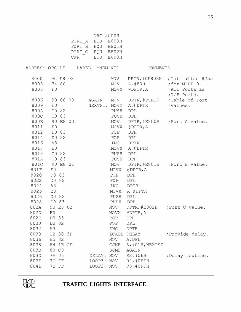
4.7 DEMONSTRATION PROGRAM FOR ESA 31 TRAINER
; Simulates the traffic situations described in example 1
; Assume the interface is connected over J2 of the trainer
; The trainer can be in KEYBOARD MODE or SERIAL MODE.
; The traffic system moves from one state to next state after a
; fixed delay
; Program memory from 8000H to 804FH
TRAFFIC LIGHTS INTERFACE
25
ORG 8000H
PORT_A EQU E800H
PORT_B EQU E801H
PORT_C EQU E802H
CWR EQU E803H
ADDRESS OPCODE LABEL MNEMONIC COMMENTS
8000 90 E8 03 MOV DPTR,#0E803H ;Initialise 8255
8003 74 80 MOV A,#80H ;for MODE 0.
8005 F0 MOVX @DPTR,A ;All Ports as
;O/P Ports.
8006 90 00 00 AGAIN: MOV DPTR,#PORTS ;Table of Port
8009 E0 NEXTST: MOVX A,@DPTR ;values.
800A C0 82 PUSH DPL
800C C0 83 PUSH DPH
800E 90 E8 00 MOV DPTR,#E800H ;Port A value.
8011 F0 MOVX @DPTR,A
8012 D0 83 POP DPH
8014 D0 82 POP DPL
8016 A3 INC DPTR
8017 E0 MOVX A,@DPTR
8018 C0 82 PUSH DPL
801A C0 83 PUSH DPH
801C 90 E8 01 MOV DPTR,#E801H ;Port B value.
801F F0 MOVX @DPTR,A
8020 D0 83 POP DPH
8022 D0 82 POP DPL
8024 A3 INC DPTR
8025 E0 MOVX A,@DPTR
8026 C0 82 PUSH DPL
8028 C0 83 PUSH DPH
802A 90 E8 02 MOV DPTR,#E802H ;Port C value.
802D F0 MOVX @DPTR,A
802E D0 83 POP DPH
8030 D0 82 POP DPL
8032 A3 INC DPTR
8033 12 80 3D LCALL DELAY ;Provide delay.
8036 E5 82 MOV A,DPL
8038 B4 1E CE CJNE A,#01H,NEXTST
803B 80 C9 SJMP AGAIN
803D 7A 06 DELAY: MOV R2,#06H ;Delay routine.
803F 7C FF LOOP3: MOV R4,#0FFH
8041 7B FF LOOP2: MOV R3,#0FFH

TRAFFIC LIGHTS INTERFACE
26
8043 1B LOOP1: DEC R3
8044 BB 00 FC CJNE R3,#00,LOOP1
8047 1C DEC R4
8048 BC 00 F6 CJNE R4,#00,LOOP2
804B 1A DEC R2
804C BA 00 F0 CJNE R2,#00,LOOP3
804F 22 RET
ENTER THE DATA MENTIONED BELOW FROM 0000 TO 001E IN DATA MEMORY.
0000 10 81 7A PORTS: DB 10H,81H,7AH ;State 1
0003 44 44 F0 DB 44H,44H,0F0H ;All Ambers ON.
0006 08 11 E5 DB 08H,11H,0E5H ;State 2
0009 44 44 F0 DB 44H,44H,0F0H ;All Ambers ON.
000C 81 10 DA DB 81H,10H,0DAH ;State 3
000F 44 44 F0 DB 44H,44H,0F0H ;All Ambers ON.
0012 11 08 B5 DB 11H,08H,0B5H ;State 4
0015 44 44 F0 DB 44H,44H,0F0H ;All Ambers ON.
0018 88 88 00 DB 88H,88H,00H ;State 5
001B 44 44 F0 DB 44H,44H,0F0H ;All Ambers ON.
001E 00 DB 00H ;DUMMY.
4.8 DEMONSTRATION PROGRAM FOR ESA 196 TRAINER
; Simulates the traffic situations described in example 1
; Assume the interface is connected over J2 of the trainer
; The trainer can be in KEYBOARD MODE or SERIAL MODE.
; The traffic system moves from one state to next state
; When "NEXT" key is pressed in KEYBOARD MODE or
; When a comma (",") is typed in SERIAL MODE
REG1 EQU 52H
REG2 EQU 54H
REG3 EQU 56H
REG4 EQU 58H
REG5 EQU 60H
PORT_A EQU 200H
PORT_B EQU 202H
PORT_C EQU 204H
CMD_PORT EQU 206H
GET_CH EQU 22E6H
ADDRESS OPCODE LABEL MNEMONIC COMMENTS

TRAFFIC LIGHTS INTERFACE
27
8000 B1 80 52 LDB REG1,#80H ;Initialise
8003 C7 01 06 02 STB REG1,CMD_PORT ;8255 for
8007 52 ;all O/P ports
8008 B1 05 56 AGAIN: LDB REG3,#05H ;5 States in a
;sequence.
800B A1 7A 80 58 LD REG4,#PORTS ;Table of port
;values.
800F B2 58 52 NEXTST: LDB REG1,[REG4]
8012 C7 01 00 02 STB REG1,PORT_A ;Port A value.
8016 52
8017 07 58 INC REG4
8019 B2 58 52 LDB REG1,[REG4]
801C C7 01 02 02 STB REG1,PORT_B ;Port B value.
8020 52
8021 07 58 INC REG4
8023 B2 58 52 LDB REG1,[REG4]
8026 C7 01 04 02 STB REG1,PORT_C ;Port C value.
802A 52
802B 07 58 INC REG4
802D 20 00 SJMP WSER
802F C8 54 WSER: PUSH REG2 ;Save counter.
8031 EF B2 A2 WSER1: LCALL GET_CH ;Get character.
8034 99 2C 20 CMPB 20H,#',' ;Is it a comma?
8037 D7 F8 JNE WSER1 ;No try again
8039 CC 54 POP REG2
803B B2 58 52 WOVER: LDB REG1,[REG4] ;Sequence for
803E C7 01 00 02 STB REG1,PORT_A ;turning on
8042 52 ;Amber.
8043 07 58 INC REG4
8045 B2 58 52 LDB REG1,[REG4]
8048 C7 01 00 02 STB REG1,PORT_A
804C 52
804D 07 58 INC REG4
804F B2 58 52 LDB REG1,[REG4]
8052 C7 01 00 02 STB REG1,PORT_A
8056 52
8057 07 58 INC REG4
8059 EF 06 00 LCALL DELAY ;Amber on period.
805C 15 56 DECB REG3 ;All states over.
805E D7 AF JNE NEXTST ;No, Next state.
8060 27 A6 SJMP AGAIN ;Repeat the
;whole sequence.
8062 B1 0F 54 DELAY: LDB REG2,#0FH ;Delay Routine.
8065 A1 FF 1F 60 DEL5: LD REG5,#1FFFH

TRAFFIC LIGHTS INTERFACE
28
8069 FD DEL10: NOP
806A FD NOP
806B 05 60 DEC REG5
806D B0 60 52 LDB REG1,REG5
8070 90 60 52 ORB REG1,REG5
8073 D7 F4 JNE DEL10
8075 15 54 DECB REG2
8077 D7 EC JNE DEL5
8079 F0 RET
807A 88 83 F2 PORTS: DCB 88H,83H,0F2H ;State 1
807D 88 87 F2 DCB 88H,87H,0F2H ;All Ambers ON.
8080 38 88 F4 DCB 38H,88H,0F4H ;State 2
8083 78 88 F4 DCB 78H,88H,0F4H ;All Ambers ON.
8086 83 88 F8 DCB 83H,88H,0F8H ;State 3
8089 87 88 F8 DCB 87H,88H,0F8H ;All Ambers ON.
808C 88 38 F1 DCB 88H,38H,0F1H ;State 4
808F 88 78 F1 DCB 88H,78H,0F1H ;All Ambers ON.
8092 88 88 00 DCB 88H,88H,00H ;State 5
8095 88 88 00 DCB 88H,88H,00H ;Dummy.
; Simulates the traffic situations described in example 2
; The traffic system moves from one state to next state
; after a fixed delay.
8000 B1 80 52 LDB REG1,#80H ;Initialise
8003 C7 01 06 02 STB REG1,CMD_PORT ;8255 for
8007 52 ;all O/P ports.
8008 A1 52 80 58 AGAIN: LD REG4,#PORTS
800C B2 58 52 NEXTST: LDB REG1,[REG4]
800F C7 01 00 02 STB REG1,PORT_A ;Port A value.
8013 52
8014 07 58 INC REG4
8016 B2 58 52 LDB REG1,[REG4]
8019 C7 01 02 02 STB REG1,PORT_B ;Port B value.
801D 52
801E 07 58 INC REG4
8020 B2 58 52 LDB REG1,[REG4]
8023 C7 01 04 02 STB REG1,PORT_C ;Port C value.
8027 52
8028 07 58 INC REG4
802A EF 0C 00 LCALL DELAY ;Some delay.
802D A1 70 80 54 LD REG2,#TEND ;End of port
;values.
8031 88 54 58 CMP REG4,REG2
8034 D7 D6 JNE NEXTST ;No, Next

TRAFFIC LIGHTS INTERFACE
29
;state.
8036 E7 CF FF LJMP AGAIN ;Repeat the
;entire
;sequence.
8039 A1 0A 00 62 DELAY: LD REG6,#0AH
803D A1 FF FF 60 DEL50: LD REG5,#0FFFFH ;Delay
8041 05 60 DEL10: DEC REG5 ;routine.
8043 89 00 00 60 CMP REG5,#00H
8047 D7 F8 JNE DEL10
8049 05 62 DEC REG6
804B 89 00 00 62 CMP REG6,#00H
804F D7 EC JNE DEL50
8051 F0 RET
8052 10 81 7A PORTS: DCB 10h,81h,07Ah ; State 1.
8055 44 44 F0 DCB 44H,44H,0F0H ; All Ambers ON.
8058 08 11 E5 DCB 08H,11H,0E5H ; State 2.
805B 44 44 F0 DCB 44H,44H,0F0H ; All Ambers ON.
805E 81 10 DA DCB 81H,10H,0DAH ; State 3.
8061 44 44 F0 DCB 44H,44H,0F0H ; All Ambers ON.
8064 11 08 B5 DCB 11H,08H,0B5H ; State 4.
8067 44 44 F0 DCB 44H,44H,0F0H ; All Ambers ON.
806A 88 88 00 DCB 88H,88H,00H ; State 5.
806D 44 44 F0 DCB 44H,44H,0F0H ; Dummy.
8070 00 TEND: DCB 00H
4.9 DEMONSTRATION PROGRAM FOR ESA 68K-2 TRAINER
; Simulates the traffic situations described in example 1
; Assume the interface is connected over J2 of the trainer
; The trainer can be in KEYBOARD MODE or SERIAL MODE.
; The traffic system moves from one state to next state
; When "NEXT" key is pressed in KEYBOARD MODE or
; When a comma (",") is typed in SERIAL MODE
ORG 400400H
PORTA EQU 800011H
PORTB EQU 800013H
PORTC EQU 800019H
PA_CT EQU 80000DH
PA_DI EQU 800005H
PB_CT EQU 80000FH
PB_DI EQU 800007H
PC_DI EQU 800009H

TRAFFIC LIGHTS INTERFACE
30
ADDRESS OPCODE LABLE MNEMONICS COMMENTS
400400 13FC 0000 START:MOVE.B #0,PA_CT ;Initialise
0080 000D ;68230 in mode 0
400408 13FC 00FF MOVE.B #$FF,PA_DI ;All ports as
0080 0005 ;Output ports
400410 13FC 0000 MOVE.B #0,PB_CT
0080 000F
400418 13FC 00FF MOVE.B #$FF,PB_DI
0080 0007
400420 13FC 00FF MOVE.B #$FF,PC_DI
0080 0009
400428 343C 0004 AGAIN:MOVE.W #$04,D2 ;5 States in a
;sequence
40042C 43F9 0040 LEA PORTS,A1 ;Table of port
049A ;values
400432 1219 NEXTST:MOVE.B (A1)+,D1
400434 13C1 0080 MOVE.B D1,PORTA ;Port A value
0011
40043A 1219 MOVE.B (A1)+,D1
40043C 13C1 0080 MOVE.B D1,PORTB ;Port B value
0013
400442 1219 MOVE.B (A1)+,D1
400444 13C1 0080 MOVE.B D1,PORTC ;Port C value
0019
40044A 48E7 2040 MOVEM.L D2/A1,-(A7) ;Save counter
;and Pointer
40044E 4EB9 0040 WAIT: JSR GETKEY
0494
400454 0C00 002C CMP.B #",",D0 ;Is it a comma
400458 66F4 BNE.S WAIT
40045A 4CDF 0204 MOVEM.L (A7)+,D2/A1 ;Restore count
;and Pointer
40045E 1219 MOVE.B (A1)+,D1 ;Sequence for
400460 13C1 0080 MOVE.B D1,PORTA ;Turning on
0011 ;AMBER
400466 1219 MOVE.B (A1)+,D1
400468 13C1 0080 MOVE.B D1,PORTB
0013
40046E 1219 MOVE.B (A1)+,D1
400470 13C1 0080 MOVE.B D1,PORTC
0019
400476 6100 0008 BSR DELAY ;AMBER ON PERIOD
40047A 51CA FFB6 DBF D2,NEXTST ;Loop for 5
;states

TRAFFIC LIGHTS INTERFACE
31
40047E 60A8 BRA.S AGAIN ;Repeat the
;whole Sequence
400480 3A3C FFFF DELAY:MOVE.W #$FFFF,D5
400484 4E71 DLY10:NOP
400486 4E71 NOP
400488 4E71 NOP
40048A 4E71 NOP
40048C 4E71 NOP
40048E 51CD FFF4 DBF D5,DLY10
400492 4E75 RTS ;Returns in D0
400494 4E4B GETKEY: TRAP #11
400496 00 0E DC.W $000EH
400498 4E75 RTS
40049A 88 83 F2 PORTS: DB 88H,83H,F2H ;State1
40049D 88 87 F2 DB 88H,87H,F2H ;Amber ON
4004A0 38 88 F4 DB 38H,88H,F4H ;State2
4004A3 78 88 F4 DB 78H,88H,F4H ;Amber ON
4004A6 83 88 F4 DB 83H,88H,F4H ;State3
4004A9 87 88 F8 DB 87H,88H,F8H ;Amber ON
4004AC 88 38 F1 DB 88H,38H,F1H ;State4
4004AF 88 78 F1 DB 88H,78H,F1H ;Amber ON
4004B2 88 88 00 DB 88H,88H,00H ;State 5
4004B5 88 88 00 DB 88H,88H,00H ;Dummy.
; Simulates the traffic situations described in example 2
; The traffic system moves from one state to next state
; after a fixed delay.
400400 13FC 0000 START:MOVE.B #0,PA_CT ;Initialise 68230
0080 000D
400408 13FC 00FF MOVE.B #$FF,PA_DI ;in mode 0
0080 0005 ;All Ports as o/p
400410 13FC 0000 MOVE.B #0,PB_CT ;Ports.
0080 000F
400418 13FC 00FF MOVE.B #$FF,PB_DI
0080 0007
400420 13FC 00FF MOVE.B #$FF,PC_DI
0080 0009
400428 43F9 0040 AGAIN:LEA PORTS,A1 ;Table of Port
0472 ;values
40042E 1219 NEXTST:MOVE.B (A1)+,D1
400430 13C1 0080 MOVE.B D1,PORTA ;Port A value
0011
400436 1219 MOVE.B (A1)+,D1
400438 13C1 0080 MOVE.B D1,PORTB ;Port B value

TRAFFIC LIGHTS INTERFACE
32
0013
40043E 1219 MOVE.B (A1)+,D1
400440 13C1 0080 MOVE.B D1,PORTC ;Port C value
0019
400446 610A BSR.S DELAY
400448 B3FC 0040 CMPA.L #TEND,A1 ;End of PORT
0490 ;values?
40044E 66DE BNE.S NEXTST ;No, Next state.
400450 60D6 BRA.S AGAIN ;Repeat the
;whole sequence.
400452 3A3C FFFF DELAY:MOVE.W #$FFFFH,D5 ;Delay Routine.
400456 4E71 DLY10:NOP
400458 4E71 NOP
40045A 4E71 NOP
40045C 4E71 NOP
40045E 4E71 NOP
400460 4E71 NOP
400462 4E71 NOP
400464 4E71 NOP
400466 4E71 NOP
400468 4E71 NOP
40046A 4E71 NOP
40046C 51CD FFE8 DBF D5,DLY10
400470 4E75 RTS
400472 10 81 7A PORTS:DB 10H,81H,7AH ;State1
400475 44 44 F0 DB 44H,44H,F0H ;Ambers ON
400478 08 11 E5 DB 08H,11H,E5H ;State2
40047B 44 44 F0 DB 44H,44H,F0H ;Amber ON
40047E 81 10 DA DB 81H,10H,DAH ;State3
400481 44 44 F0 DB 44H,44H,F0H ;Amber ON
400484 11 08 B5 DB 11H,08H,B5H ;State4
400487 44 44 F0 DB 44H,44H,F0H ;Amber ON
40048A 88 88 00 DB 88H,88H,00H ;State 5
40048D 44 44 F0 DB 44H,44H,F0H ;Amber ON
400490 00 TEND:DB 00H ;Dummy.
4.10 DEMONSTRATION PROGRAM FOR ESA 51 TRAINER
;Assume the interface is connected to J10 of trainer.
;The trainer ESA-51 can be in KEYBOARD MODE or in SERIAL MODE.
;The Traffic System moves from one state to next state after
;a fixed time delay.
PORT_A EQU E800H

TRAFFIC LIGHTS INTERFACE
33
PORT_B EQU E801H
PORT_C EQU E802H
CWR EQU E803H
ADDRESS OPCODE LABEL MNEMONIC COMMENTS
8000 ORG 8000H
8000 90 E8 03 MOV DPTR,#CWR ;Initialise 8255
8003 74 80 MOV A,#80H ;for MODE 0.
8005 F0 MOVX @DPTR,A ;All Ports as
;O/P Ports.
8006 90 00 00 AGAIN: MOV DPTR,#0000H ;Table of Port
8009 E0 NEXTST:MOVX A,@DPTR ;values.
800A C0 82 PUSH DPL
800C C0 83 PUSH DPH
800E 90 E8 00 MOV DPTR,#PORT_A ;Port A value.
8011 F0 MOVX @DPTR,A
8012 D0 83 POP DPH
8014 D0 82 POP DPL
8016 A3 INC DPTR
8017 E0 MOVX A,@DPTR
8018 C0 82 PUSH DPL
801A C0 83 PUSH DPH
801C 90 E8 01 MOV DPTR,#PORT_B ;Port B value.
801F F0 MOVX @DPTR,A
8020 D0 83 POP DPH
8022 D0 82 POP DPL
8024 A3 INC DPTR
8025 E0 MOVX A,@DPTR
8026 C0 82 PUSH DPL
8028 C0 83 PUSH DPH
802A 90 E8 02 MOV DPTR,#PORT_C ;Port C value.
802D F0 MOVX @DPTR,A
802E D0 83 POP DPH
8030 D0 82 POP DPL
8032 A3 INC DPTR
8033 12 80 3D CALL DELAY ;Provide delay.
8036 E5 82 MOV A,DPL
8038 B4 01 CE CJNE A,#1EH,NEXTST
803B 80 C9 SJMP AGAIN
803D 7A 07 DELAY: MOV R2,#07H ;Delay routine.
803F 7C FF LOOP3: MOV R4,#0FFH
8041 7B FF LOOP2: MOV R3,#0FFH
8043 1B LOOP1: DEC R3
8044 BB 00 FC CJNE R3,#00,LOOP1

TRAFFIC LIGHTS INTERFACE
34
8047 1C DEC R4
8048 BC 00 F6 CJNE R4,#00,LOOP2
804B 1A DEC R2
804C BA 00 F0 CJNE R2,#00,LOOP3
804F 22 RET
ENTER THE BELOW GIVEN DATA FROM 0000 TO 001E AT DATA MEMORY
0000 10 81 7A PORTS: DB 10H,81H,7AH ;State 1
0003 44 44 F0 DB 44H,44H,0F0H ;All Ambers ON.
0006 08 11 E5 DB 08H,11H,0E5H ;State 2
0009 44 44 F0 DB 44H,44H,0F0H ;All Ambers ON.
000C 81 10 DA DB 81H,10H,0DAH ;State 3
000F 44 44 F0 DB 44H,44H,0F0H ;All Ambers ON.
0012 11 08 B5 DB 11H,08H,0B5H ;State 4
0015 44 44 F0 DB 44H,44H,0F0H ;All Ambers ON.
0018 88 88 00 DB 88H,88H,00H ;State 5
001B 44 44 F0 DB 44H,44H,0F0H ;All Ambers ON.
001E 00 DB 00H ;DUMMY.
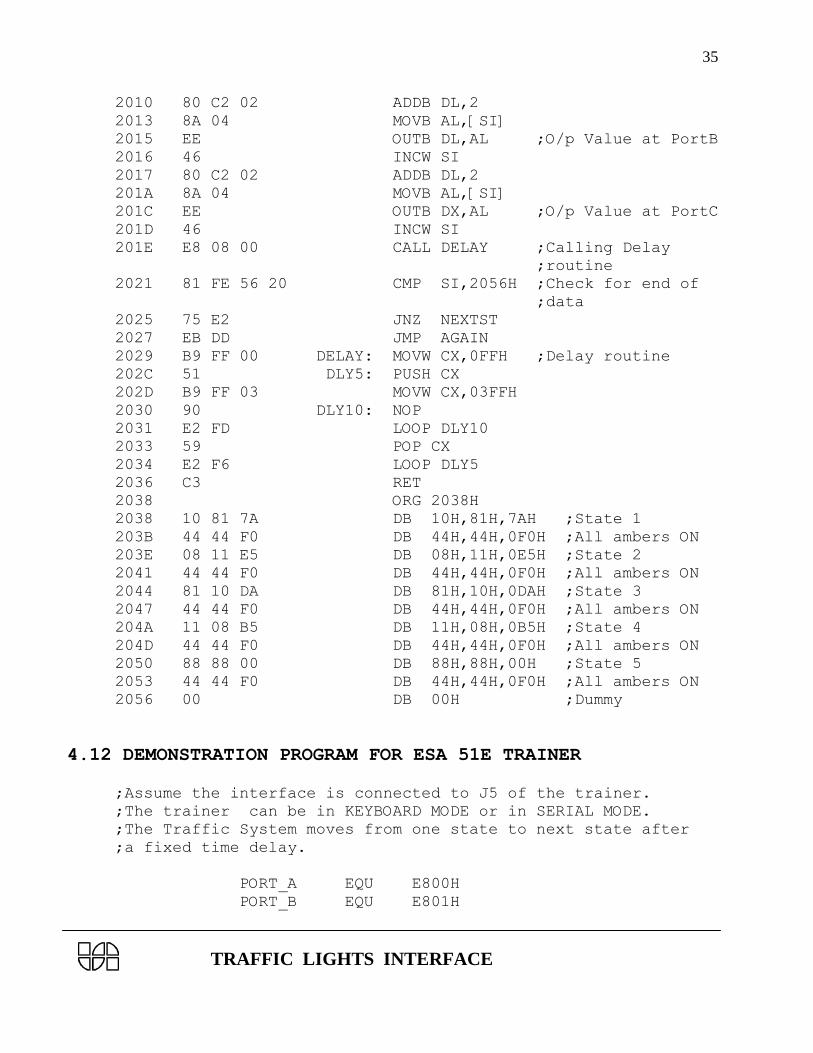
4.11 DEMONSTRATION PROGRAM FOR ESA 86/88-3 TRAINER
; Simulates the traffic situations described in example 1
; Assume the interface is connected over J8 of the trainer
; The trainer can be in KEYBOARD MODE or SERIAL MODE.
; The traffic system moves from one state to next state after a
; fixed delay
; The program starts at memory location 0:2000H
; Please refer ESA 86/88-3 user's manual for mnemonic syntax
; suitable to trainer
Code Segment :0000H
ADDRESS OPCODE LABEL MNEMONIC COMMENTS
2000 B0 80 START: MOVB AL,80H ;Initialise 8255
;in Mode 0
2002 BA E6 FF MOVW DX,0FFE6H
2005 EE OUTB DX,AL ;All ports as o/p
2006 BE 38 20 AGAIN: MOVW SI,2038H ;Load able of port
;values
2009 8A 04 NEXTST: MOVB AL,[SI]
200B BA E0 FF MOVW DX,0FFE0H
200E EE OUTB DX,AL ;O/p Value at PortA
200F 46 INCW SI
TRAFFIC LIGHTS INTERFACE
35
2010 80 C2 02 ADDB DL,2
2013 8A 04 MOVB AL,[SI]
2015 EE OUTB DL,AL ;O/p Value at PortB
2016 46 INCW SI
2017 80 C2 02 ADDB DL,2
201A 8A 04 MOVB AL,[SI]
201C EE OUTB DX,AL ;O/p Value at PortC
201D 46 INCW SI
201E E8 08 00 CALL DELAY ;Calling Delay
;routine
2021 81 FE 56 20 CMP SI,2056H ;Check for end of
;data
2025 75 E2 JNZ NEXTST
2027 EB DD JMP AGAIN
2029 B9 FF 00 DELAY: MOVW CX,0FFH ;Delay routine
202C 51 DLY5: PUSH CX
202D B9 FF 03 MOVW CX,03FFH
2030 90 DLY10: NOP
2031 E2 FD LOOP DLY10
2033 59 POP CX
2034 E2 F6 LOOP DLY5
2036 C3 RET
2038 ORG 2038H
2038 10 81 7A DB 10H,81H,7AH ;State 1
203B 44 44 F0 DB 44H,44H,0F0H ;All ambers ON
203E 08 11 E5 DB 08H,11H,0E5H ;State 2
2041 44 44 F0 DB 44H,44H,0F0H ;All ambers ON
2044 81 10 DA DB 81H,10H,0DAH ;State 3
2047 44 44 F0 DB 44H,44H,0F0H ;All ambers ON
204A 11 08 B5 DB 11H,08H,0B5H ;State 4
204D 44 44 F0 DB 44H,44H,0F0H ;All ambers ON
2050 88 88 00 DB 88H,88H,00H ;State 5
2053 44 44 F0 DB 44H,44H,0F0H ;All ambers ON
2056 00 DB 00H ;Dummy
4.12 DEMONSTRATION PROGRAM FOR ESA 51E TRAINER
;Assume the interface is connected to J5 of the trainer.
;The trainer can be in KEYBOARD MODE or in SERIAL MODE.
;The Traffic System moves from one state to next state after
;a fixed time delay.
PORT_A EQU E800H
PORT_B EQU E801H

TRAFFIC LIGHTS INTERFACE
36
PORT_C EQU E802H
CWR EQU E803H
ADDRESS OPCODE LABEL MNEMONIC COMMENTS
8000 ORG 8000H
8000 90 E8 03 MOV DPTR,#CWR ;Initialise
8003 74 80 MOV A,#80H ;8255for MODE 0.
8005 F0 MOVX @DPTR,A ;All Ports as
;O/P Ports.
8006 90 00 00 AGAIN: MOV DPTR,#0000H ;Table of Port
8009 E0 NEXTST: MOVX A,@DPTR ;values.
800A C0 82 PUSH DPL
800C C0 83 PUSH DPH
800E 90 E8 00 MOV DPTR,#PORT_A ;Port A value.
8011 F0 MOVX @DPTR,A
8012 D0 83 POP DPH
8014 D0 82 POP DPL
8016 A3 INC DPTR
8017 E0 MOVX A,@DPTR
8018 C0 82 PUSH DPL
801A C0 83 PUSH DPH
801C 90 E8 01 MOV DPTR,#PORT_B ;Port B value.
801F F0 MOVX @DPTR,A
8020 D0 83 POP DPH
8022 D0 82 POP DPL
8024 A3 INC DPTR
8025 E0 MOVX A,@DPTR
8026 C0 82 PUSH DPL
8028 C0 83 PUSH DPH
802A 90 E8 02 MOV DPTR,#PORT_C ;Port C value.
802D F0 MOVX @DPTR,A
802E D0 83 POP DPH
8030 D0 82 POP DPL
8032 A3 INC DPTR
8033 12 80 3D CALL DELAY ;Provide delay.
8036 E5 82 MOV A,DPL
8038 B4 1E CE CJNE A,#1EH,NEXTST
803B 80 C9 SJMP AGAIN
803D 7A 07 DELAY: MOV R2,#07H ;Delay routine.
803F 7C FF LOOP3: MOV R4,#0FFH
8041 7B FF LOOP2: MOV R3,#0FFH
8043 1B LOOP1: DEC R3
8044 BB 00 FC CJNE R3,#00,LOOP1
8047 1C DEC R4

TRAFFIC LIGHTS INTERFACE
37
8048 BC 00 F6 CJNE R4,#00,LOOP2
804B 1A DEC R2
804C BA 00 F0 CJNE R2,#00,LOOP3
804F 22 RET
ENTER THE BELOW GIVEN DATA FROM 0000 TO 001E AT DATA MEMORY
0000 10 81 7A PORTS: DB 10H,81H,7AH ;State 1
0003 44 44 F0 DB 44H,44H,0F0H ;All Ambers ON.
0006 08 11 E5 DB 08H,11H,0E5H ;State 2
0009 44 44 F0 DB 44H,44H,0F0H ;All Ambers ON.
000C 81 10 DA DB 81H,10H,0DAH ;State 3
000F 44 44 F0 DB 44H,44H,0F0H ;All Ambers ON.
0012 11 08 B5 DB 11H,08H,0B5H ;State 4
0015 44 44 F0 DB 44H,44H,0F0H ;All Ambers ON.
0018 88 88 00 DB 88H,88H,00H ;State 5
001B 44 44 F0 DB 44H,44H,0F0H ;All Ambers ON.
001E 00 DB 00H ;DUMMY.
4.13 DEMONSTRATION PROGRAM FOR ESA 86/88E TRAINER
; Simulates the traffic situations described in example 1
; Assume the interface is connected over J4 of the trainer
; The trainer can be in KEYBOARD MODE or SERIAL MODE.
; The traffic system moves from one state to next state after a
; fixed delay
; The program starts at memory location 0:2000H
; Please refer ESA 86/88E user's manual for mnemonic syntax
; suitable to trainer
Code Segment :0000H
ADDRESS OPCODE LABEL MNEMONIC COMMENTS
2000 B0 80 START: MOVB AL,80H ;Initialise 8255
;in Mode 0
2002 BA E6 FF MOVW DX,0FFE6H
2005 EE OUTB DX,AL ;All ports as o/p
2006 BE 38 20 AGAIN: MOVW SI,2038H ;Load able of port
;values
2009 8A 04 NEXTST: MOVB AL,[SI]
200B BA E0 FF MOVW DX,0FFE0H
200E EE OUTB DX,AL ;O/p Value at PortA
200F 46 INCW SI
2010 80 C2 02 ADDB DL,2

TRAFFIC LIGHTS INTERFACE
38
2013 8A 04 MOVB AL,[SI]
2015 EE OUTB DL,AL ;O/p Value at PortB
2016 46 INCW SI
2017 80 C2 02 ADDB DL,2
201A 8A 04 MOVB AL,[SI]
201C EE OUTB DX,AL ;O/p Value at PortC
201D 46 INCW SI
201E E8 08 00 CALL DELAY ;Calling Delay
;routine
2021 81 FE 56 20 CMP SI,2056H ;Check for end of
;data
2025 75 E2 JNZ NEXTST
2027 EB DD JMP AGAIN
2029 B9 FF 00 DELAY: MOVW CX,0FFH ;Delay routine
202C 51 DLY5: PUSH CX
202D B9 FF 03 MOVW CX,03FFH
2030 90 DLY10: NOP
2031 E2 FD LOOP DLY10
2033 59 POP CX
2034 E2 F6 LOOP DLY5
2036 C3 RET
2038 ORG 2038H
2038 10 81 7A DB 10H,81H,7AH ;State 1
203B 44 44 F0 DB 44H,44H,0F0H ;All ambers ON
203E 08 11 E5 DB 08H,11H,0E5H ;State 2
2041 44 44 F0 DB 44H,44H,0F0H ;All ambers ON
2044 81 10 DA DB 81H,10H,0DAH ;State 3
2047 44 44 F0 DB 44H,44H,0F0H ;All ambers ON
204A 11 08 B5 DB 11H,08H,0B5H ;State 4
204D 44 44 F0 DB 44H,44H,0F0H ;All ambers ON
2050 88 88 00 DB 88H,88H,00H ;State 5
2053 44 44 F0 DB 44H,44H,0F0H ;All ambers ON
2056 00 DB 00H ;Dummy