integrator’s reference manual for polycom hdx...
TRANSCRIPT

3.0.3 | October 2011 | 3725-23979-009/A
Integrator’s Reference Manual for Polycom® HDX® Systems

© 2011 Polycom, Inc. All rights reserved.
Polycom, Inc.4750 Willow RoadPleasanton, CA 94588-2708USA
No part of this document may be reproduced or transmitted in any form or by any means, electronic or mechanical, for any purpose, without the express written permission of Polycom, Inc. Under the law, reproducing includes translating into another language or format.
As between the parties, Polycom, Inc., retains title to and ownership of all proprietary rights with respect to the software contained within its products. The software is protected by United States copyright laws and international treaty provision. Therefore, you must treat the software like any other copyrighted material (e.g., a book or sound recording).
Every effort has been made to ensure that the information in this manual is accurate. Polycom, Inc., is not responsible for printing or clerical errors. Information in this document is subject to change without notice.
ii
Trademark Information
Polycom®, the Polycom “Triangles” logo, and the names and marks associated with Polycom’s products are trademarks and/or service marks of Polycom, Inc., and are registered and/or common-law marks in the United States and various other countries.
All other trademarks are the property of their respective owners.
Patent Information
The accompanying product may be protected by one or more U.S. and foreign patents and/or pending patent applications held by Polycom, Inc.
Customer Feedback
We are constantly working to improve the quality of our documentation, and we would appreciate your feedback. Please send email to [email protected].

Polycom, Inc. iii
About This Guide
The Integrator’s Reference Manual for Polycom® HDX® Systems is for system integrators who need to configure, customize, manage, and troubleshoot Polycom HDX systems. The API commands in this guide are applicable to the Polycom HDX 9000 series, Polycom HDX 8000 HD series, Polycom HDX 7000 HD series and Polycom HDX 6000 HD series systems.

Integrator’s Reference Manual for Polycom HDX Systems About This Guide
iv Polycom, Inc.

Polycom, Inc. v
Contents
About This Guide . . . . . . . . . . . . . . . . . . . . . . . . . . . . . . . . iii
1 Room IntegrationSetting Up a Room for Video Conferencing . . . . . . . . . . . . . . . . . . . . . . . . 1–1
Room Layout Examples . . . . . . . . . . . . . . . . . . . . . . . . . . . . . . . . . . . . . . 1–1Setting Up the Room for Polycom People On Content™ . . . . . . . . . . 1–3Polycom HDX Installation Precautions . . . . . . . . . . . . . . . . . . . . . . . . . 1–4
Integrating Video . . . . . . . . . . . . . . . . . . . . . . . . . . . . . . . . . . . . . . . . . . . . . . . 1–5Connecting Polycom Cameras . . . . . . . . . . . . . . . . . . . . . . . . . . . . . . . . 1–5Connecting Sony and ELMO Cameras . . . . . . . . . . . . . . . . . . . . . . . . 1–17Connecting Vaddio and Canon Cameras . . . . . . . . . . . . . . . . . . . . . . 1–19
Integrating Audio and Content . . . . . . . . . . . . . . . . . . . . . . . . . . . . . . . . . . 1–21Connecting a Computer to a Polycom HDX 9000 Series System . . 1–21Connecting a Vortex® Mixer to a Polycom HDX 9000 Series System . . . . . . . . . . . . . . . . . . . . . . . . . . . . . . . . . . . . . . . . . . . . . . . . . . . 1–25Connecting a Polycom SoundStructure C-Series Mixer to a Polycom HDX 9000 Series System . . . . . . . . . . . . . . . . . . . . . . . . . . . . 1–26
2 CablesNetwork Cables . . . . . . . . . . . . . . . . . . . . . . . . . . . . . . . . . . . . . . . . . . . . . . . . 2–1
CAT 5e LAN Cable . . . . . . . . . . . . . . . . . . . . . . . . . . . . . . . . . . . . . . . . . . 2–1LAN Cable . . . . . . . . . . . . . . . . . . . . . . . . . . . . . . . . . . . . . . . . . . . . . . . . . 2–3Polycom Touch Control LAN Cable . . . . . . . . . . . . . . . . . . . . . . . . . . . 2–4ISDN Cable . . . . . . . . . . . . . . . . . . . . . . . . . . . . . . . . . . . . . . . . . . . . . . . . 2–5Analog Telephone (POTS) Cable . . . . . . . . . . . . . . . . . . . . . . . . . . . . . . 2–7V.35/RS-449/RS-530 Serial Adapter . . . . . . . . . . . . . . . . . . . . . . . . . . . 2–8V.35 NIC Cable . . . . . . . . . . . . . . . . . . . . . . . . . . . . . . . . . . . . . . . . . . . . . 2–9V.35 and RS-366 Serial Cable . . . . . . . . . . . . . . . . . . . . . . . . . . . . . . . . 2–10RS-449 and RS-366 Serial Cable . . . . . . . . . . . . . . . . . . . . . . . . . . . . . . 2–11RS-530 with RS-366 Serial Cable . . . . . . . . . . . . . . . . . . . . . . . . . . . . . . 2–13Polycom Touch Control Power Adapter . . . . . . . . . . . . . . . . . . . . . . . 2–15
Video and Camera Cables . . . . . . . . . . . . . . . . . . . . . . . . . . . . . . . . . . . . . . 2–16
Integrator’s Reference Manual for Polycom HDX Systems
vi Polycom, Inc.
S-Video Cable . . . . . . . . . . . . . . . . . . . . . . . . . . . . . . . . . . . . . . . . . . . . . 2–16BNC to S-Video Cable . . . . . . . . . . . . . . . . . . . . . . . . . . . . . . . . . . . . . . 2–17BNC to S-Video Adapter . . . . . . . . . . . . . . . . . . . . . . . . . . . . . . . . . . . . 2–18S-Video to RCA Adapter . . . . . . . . . . . . . . . . . . . . . . . . . . . . . . . . . . . . 2–19DVI to VGA Monitor Cable . . . . . . . . . . . . . . . . . . . . . . . . . . . . . . . . . . 2–20HDMI Monitor Cable . . . . . . . . . . . . . . . . . . . . . . . . . . . . . . . . . . . . . . . 2–21BNC Monitor Adapter Cable . . . . . . . . . . . . . . . . . . . . . . . . . . . . . . . . 2–22Polycom HDX Component Monitor Cable . . . . . . . . . . . . . . . . . . . . . 2–23HDX Component Video Cable . . . . . . . . . . . . . . . . . . . . . . . . . . . . . . . 2–24DVI-D Monitor Cable . . . . . . . . . . . . . . . . . . . . . . . . . . . . . . . . . . . . . . . 2–25Component A/V Monitor Cable . . . . . . . . . . . . . . . . . . . . . . . . . . . . . 2–26HDCI Analog Camera Cable . . . . . . . . . . . . . . . . . . . . . . . . . . . . . . . . 2–27HDCI Polycom EagleEye Director Camera Cable . . . . . . . . . . . . . . . 2–28HDCI Camera Break-Out Cable . . . . . . . . . . . . . . . . . . . . . . . . . . . . . . 2–30VCR/DVD Composite Cable . . . . . . . . . . . . . . . . . . . . . . . . . . . . . . . . 2–31Composite Video Cable . . . . . . . . . . . . . . . . . . . . . . . . . . . . . . . . . . . . . 2–32PowerCam Plus Primary Cable . . . . . . . . . . . . . . . . . . . . . . . . . . . . . . 2–33HDCI PowerCam Cable . . . . . . . . . . . . . . . . . . . . . . . . . . . . . . . . . . . . . 2–34HDCI PowerCam Plus Adapter Cable . . . . . . . . . . . . . . . . . . . . . . . . 2–35HDCI VISCA Adapter Cable . . . . . . . . . . . . . . . . . . . . . . . . . . . . . . . . 2–36HDCI Polycom EagleEye 1080 Camera Cable . . . . . . . . . . . . . . . . . . 2–37HDCI Polycom EagleEye View Camera Cable . . . . . . . . . . . . . . . . . 2–38HDCI Sony VISCA Adapter Cable . . . . . . . . . . . . . . . . . . . . . . . . . . . 2–39HDCI EagleEye 1080 or Sony Adapter Cable . . . . . . . . . . . . . . . . . . . 2–40PowerCam Primary Camera Cable . . . . . . . . . . . . . . . . . . . . . . . . . . . 2–41PowerCam Break-Out Cable . . . . . . . . . . . . . . . . . . . . . . . . . . . . . . . . . 2–42PowerCam Plus/VISCA Control Cable . . . . . . . . . . . . . . . . . . . . . . . 2–43People+Content Cable . . . . . . . . . . . . . . . . . . . . . . . . . . . . . . . . . . . . . . 2–45
Audio Cables . . . . . . . . . . . . . . . . . . . . . . . . . . . . . . . . . . . . . . . . . . . . . . . . . 2–46Polycom HDX Microphone Host Cable . . . . . . . . . . . . . . . . . . . . . . . 2–46Polycom HDX Microphone Array Cable . . . . . . . . . . . . . . . . . . . . . . 2–48Polycom HDX Microphone Array Cable Adapter . . . . . . . . . . . . . . 2–49Polycom HDX Ceiling Microphone Adaptor Cable . . . . . . . . . . . . . 2–50Custom Cabling for Polycom HDX Microphones . . . . . . . . . . . . . . . 2–51Audio Adapter Cable . . . . . . . . . . . . . . . . . . . . . . . . . . . . . . . . . . . . . . . 2–54Audio Cable . . . . . . . . . . . . . . . . . . . . . . . . . . . . . . . . . . . . . . . . . . . . . . . 2–55Vortex Cable . . . . . . . . . . . . . . . . . . . . . . . . . . . . . . . . . . . . . . . . . . . . . . 2–563.5mm Screw Cage Connector . . . . . . . . . . . . . . . . . . . . . . . . . . . . . . . 2–57Subwoofer Volume Attenuator . . . . . . . . . . . . . . . . . . . . . . . . . . . . . . 2–58

Contents
Polycom, Inc. vii
Polycom EagleEye Director Audio Feedback Phoenix to Phoenix Cable . . . . . . . . . . . . . . . . . . . . . . . . . . . . . . . . . . . . . . . . . . . . . 2–59
Serial Cables . . . . . . . . . . . . . . . . . . . . . . . . . . . . . . . . . . . . . . . . . . . . . . . . . . 2–60Straight-Through Serial Cable . . . . . . . . . . . . . . . . . . . . . . . . . . . . . . . 2–60Null Modem Adapter . . . . . . . . . . . . . . . . . . . . . . . . . . . . . . . . . . . . . . 2–62
3 Using the APIUsing the API with an RS-232 Interface . . . . . . . . . . . . . . . . . . . . . . . . . . . . 3–1
Configuring the RS-232 Interface . . . . . . . . . . . . . . . . . . . . . . . . . . . . . . 3–1Starting an API Session using an RS-232 Interface . . . . . . . . . . . . . . . 3–3Using the API with the Maximum Security Profile Enabled . . . . . . . 3–4
Using the API with a LAN Connection . . . . . . . . . . . . . . . . . . . . . . . . . . . . 3–4Using the API Controller Code . . . . . . . . . . . . . . . . . . . . . . . . . . . . . . . . . . . 3–4Additional API Resources . . . . . . . . . . . . . . . . . . . . . . . . . . . . . . . . . . . . . . . 3–5
Technical Support Contact Information . . . . . . . . . . . . . . . . . . . . . . . . 3–5Feature Enhancement Request Web Site . . . . . . . . . . . . . . . . . . . . . . . . 3–5Video Test Numbers . . . . . . . . . . . . . . . . . . . . . . . . . . . . . . . . . . . . . . . . 3–5Knowledge Base . . . . . . . . . . . . . . . . . . . . . . . . . . . . . . . . . . . . . . . . . . . . 3–5
4 System CommandsAbout the API Commands . . . . . . . . . . . . . . . . . . . . . . . . . . . . . . . . . . . . . . . 4–2
Syntax Conventions . . . . . . . . . . . . . . . . . . . . . . . . . . . . . . . . . . . . . . . . . 4–2Availability of Commands . . . . . . . . . . . . . . . . . . . . . . . . . . . . . . . . . . . 4–2Command Response Syntax . . . . . . . . . . . . . . . . . . . . . . . . . . . . . . . . . . 4–3Commands that Restart the System . . . . . . . . . . . . . . . . . . . . . . . . . . . . 4–5Additional Tips . . . . . . . . . . . . . . . . . . . . . . . . . . . . . . . . . . . . . . . . . . . . . 4–5
! . . . . . . . . . . . . . . . . . . . . . . . . . . . . . . . . . . . . . . . . . . . . . . . . . . . . . . . . . . . . . . 4–7abk (deprecated) . . . . . . . . . . . . . . . . . . . . . . . . . . . . . . . . . . . . . . . . . . . . . . . 4–9addrbook . . . . . . . . . . . . . . . . . . . . . . . . . . . . . . . . . . . . . . . . . . . . . . . . . . . . . 4–12addressdisplayedingab . . . . . . . . . . . . . . . . . . . . . . . . . . . . . . . . . . . . . . . . . 4–14advnetstats . . . . . . . . . . . . . . . . . . . . . . . . . . . . . . . . . . . . . . . . . . . . . . . . . . . 4–15alertusertone . . . . . . . . . . . . . . . . . . . . . . . . . . . . . . . . . . . . . . . . . . . . . . . . . . 4–17alertvideotone . . . . . . . . . . . . . . . . . . . . . . . . . . . . . . . . . . . . . . . . . . . . . . . . . 4–18all register . . . . . . . . . . . . . . . . . . . . . . . . . . . . . . . . . . . . . . . . . . . . . . . . . . . . 4–19all unregister . . . . . . . . . . . . . . . . . . . . . . . . . . . . . . . . . . . . . . . . . . . . . . . . . . 4–21allowabkchanges . . . . . . . . . . . . . . . . . . . . . . . . . . . . . . . . . . . . . . . . . . . . . . 4–22allowcamerapresetssetup . . . . . . . . . . . . . . . . . . . . . . . . . . . . . . . . . . . . . . . 4–23allowdialing . . . . . . . . . . . . . . . . . . . . . . . . . . . . . . . . . . . . . . . . . . . . . . . . . . 4–24allowmixedcalls . . . . . . . . . . . . . . . . . . . . . . . . . . . . . . . . . . . . . . . . . . . . . . . 4–25allowusersetup . . . . . . . . . . . . . . . . . . . . . . . . . . . . . . . . . . . . . . . . . . . . . . . . 4–26

Integrator’s Reference Manual for Polycom HDX Systems
viii Polycom, Inc.
amxdd . . . . . . . . . . . . . . . . . . . . . . . . . . . . . . . . . . . . . . . . . . . . . . . . . . . . . . . 4–27answer . . . . . . . . . . . . . . . . . . . . . . . . . . . . . . . . . . . . . . . . . . . . . . . . . . . . . . . 4–28areacode . . . . . . . . . . . . . . . . . . . . . . . . . . . . . . . . . . . . . . . . . . . . . . . . . . . . . 4–29audiometer . . . . . . . . . . . . . . . . . . . . . . . . . . . . . . . . . . . . . . . . . . . . . . . . . . . 4–30audiotransmitlevel . . . . . . . . . . . . . . . . . . . . . . . . . . . . . . . . . . . . . . . . . . . . . 4–32autoanswer . . . . . . . . . . . . . . . . . . . . . . . . . . . . . . . . . . . . . . . . . . . . . . . . . . . 4–34autoshowcontent . . . . . . . . . . . . . . . . . . . . . . . . . . . . . . . . . . . . . . . . . . . . . . 4–35backlightcompensation . . . . . . . . . . . . . . . . . . . . . . . . . . . . . . . . . . . . . . . . . 4–36basicmode . . . . . . . . . . . . . . . . . . . . . . . . . . . . . . . . . . . . . . . . . . . . . . . . . . . . 4–37bri1enable, bri2enable, bri3enable, bri4enable . . . . . . . . . . . . . . . . . . . . . 4–38briallenable . . . . . . . . . . . . . . . . . . . . . . . . . . . . . . . . . . . . . . . . . . . . . . . . . . . 4–39button . . . . . . . . . . . . . . . . . . . . . . . . . . . . . . . . . . . . . . . . . . . . . . . . . . . . . . . . 4–40calendardomain . . . . . . . . . . . . . . . . . . . . . . . . . . . . . . . . . . . . . . . . . . . . . . . 4–44calendarmeetings . . . . . . . . . . . . . . . . . . . . . . . . . . . . . . . . . . . . . . . . . . . . . . 4–45calendarpassword . . . . . . . . . . . . . . . . . . . . . . . . . . . . . . . . . . . . . . . . . . . . . 4–50calendarplaytone . . . . . . . . . . . . . . . . . . . . . . . . . . . . . . . . . . . . . . . . . . . . . . 4–51calendarregisterwithserver . . . . . . . . . . . . . . . . . . . . . . . . . . . . . . . . . . . . . . 4–52calendarremindertime . . . . . . . . . . . . . . . . . . . . . . . . . . . . . . . . . . . . . . . . . . 4–53calendarresource . . . . . . . . . . . . . . . . . . . . . . . . . . . . . . . . . . . . . . . . . . . . . . 4–54calendarserver . . . . . . . . . . . . . . . . . . . . . . . . . . . . . . . . . . . . . . . . . . . . . . . . 4–55calendarshowpvtmeetings . . . . . . . . . . . . . . . . . . . . . . . . . . . . . . . . . . . . . . 4–56calendarstatus . . . . . . . . . . . . . . . . . . . . . . . . . . . . . . . . . . . . . . . . . . . . . . . . . 4–57calendaruser . . . . . . . . . . . . . . . . . . . . . . . . . . . . . . . . . . . . . . . . . . . . . . . . . . 4–58calldetail . . . . . . . . . . . . . . . . . . . . . . . . . . . . . . . . . . . . . . . . . . . . . . . . . . . . . 4–59calldetailreport . . . . . . . . . . . . . . . . . . . . . . . . . . . . . . . . . . . . . . . . . . . . . . . . 4–60callinfo . . . . . . . . . . . . . . . . . . . . . . . . . . . . . . . . . . . . . . . . . . . . . . . . . . . . . . . 4–61callstate . . . . . . . . . . . . . . . . . . . . . . . . . . . . . . . . . . . . . . . . . . . . . . . . . . . . . . 4–62callstats . . . . . . . . . . . . . . . . . . . . . . . . . . . . . . . . . . . . . . . . . . . . . . . . . . . . . . 4–64camera . . . . . . . . . . . . . . . . . . . . . . . . . . . . . . . . . . . . . . . . . . . . . . . . . . . . . . . 4–65cameradirection . . . . . . . . . . . . . . . . . . . . . . . . . . . . . . . . . . . . . . . . . . . . . . . 4–69camerainput . . . . . . . . . . . . . . . . . . . . . . . . . . . . . . . . . . . . . . . . . . . . . . . . . . 4–70chaircontrol . . . . . . . . . . . . . . . . . . . . . . . . . . . . . . . . . . . . . . . . . . . . . . . . . . . 4–71clientvalidatepeercert . . . . . . . . . . . . . . . . . . . . . . . . . . . . . . . . . . . . . . . . . . 4–73cmdecho . . . . . . . . . . . . . . . . . . . . . . . . . . . . . . . . . . . . . . . . . . . . . . . . . . . . . 4–74colorbar . . . . . . . . . . . . . . . . . . . . . . . . . . . . . . . . . . . . . . . . . . . . . . . . . . . . . . 4–75configchange (deprecated) . . . . . . . . . . . . . . . . . . . . . . . . . . . . . . . . . . . . . . 4–76configdisplay . . . . . . . . . . . . . . . . . . . . . . . . . . . . . . . . . . . . . . . . . . . . . . . . . 4–77configparam . . . . . . . . . . . . . . . . . . . . . . . . . . . . . . . . . . . . . . . . . . . . . . . . . . 4–79configpresentation . . . . . . . . . . . . . . . . . . . . . . . . . . . . . . . . . . . . . . . . . . . . . 4–80confirmdiradd . . . . . . . . . . . . . . . . . . . . . . . . . . . . . . . . . . . . . . . . . . . . . . . . 4–82

Contents
Polycom, Inc. ix
confirmdirdel . . . . . . . . . . . . . . . . . . . . . . . . . . . . . . . . . . . . . . . . . . . . . . . . . 4–83contentauto . . . . . . . . . . . . . . . . . . . . . . . . . . . . . . . . . . . . . . . . . . . . . . . . . . . 4–84contentsplash . . . . . . . . . . . . . . . . . . . . . . . . . . . . . . . . . . . . . . . . . . . . . . . . . 4–85contentvideoadjustment . . . . . . . . . . . . . . . . . . . . . . . . . . . . . . . . . . . . . . . . 4–86country . . . . . . . . . . . . . . . . . . . . . . . . . . . . . . . . . . . . . . . . . . . . . . . . . . . . . . 4–87cts . . . . . . . . . . . . . . . . . . . . . . . . . . . . . . . . . . . . . . . . . . . . . . . . . . . . . . . . . . . 4–88daylightsavings . . . . . . . . . . . . . . . . . . . . . . . . . . . . . . . . . . . . . . . . . . . . . . . 4–89dcd . . . . . . . . . . . . . . . . . . . . . . . . . . . . . . . . . . . . . . . . . . . . . . . . . . . . . . . . . . 4–90dcdfilter . . . . . . . . . . . . . . . . . . . . . . . . . . . . . . . . . . . . . . . . . . . . . . . . . . . . . . 4–91defaultgateway . . . . . . . . . . . . . . . . . . . . . . . . . . . . . . . . . . . . . . . . . . . . . . . . 4–92destunreachabletx . . . . . . . . . . . . . . . . . . . . . . . . . . . . . . . . . . . . . . . . . . . . . 4–93dhcp . . . . . . . . . . . . . . . . . . . . . . . . . . . . . . . . . . . . . . . . . . . . . . . . . . . . . . . . . 4–94dial . . . . . . . . . . . . . . . . . . . . . . . . . . . . . . . . . . . . . . . . . . . . . . . . . . . . . . . . . . 4–95dialchannels . . . . . . . . . . . . . . . . . . . . . . . . . . . . . . . . . . . . . . . . . . . . . . . . . . 4–99diffservaudio, diffservfecc, diffservvideo . . . . . . . . . . . . . . . . . . . . . . . . 4–100directory . . . . . . . . . . . . . . . . . . . . . . . . . . . . . . . . . . . . . . . . . . . . . . . . . . . . 4–101display (deprecated) . . . . . . . . . . . . . . . . . . . . . . . . . . . . . . . . . . . . . . . . . . 4–102displayglobaladdresses . . . . . . . . . . . . . . . . . . . . . . . . . . . . . . . . . . . . . . . . 4–104displaygraphics . . . . . . . . . . . . . . . . . . . . . . . . . . . . . . . . . . . . . . . . . . . . . . 4–105displayipext . . . . . . . . . . . . . . . . . . . . . . . . . . . . . . . . . . . . . . . . . . . . . . . . . 4–106displayipisdninfo (deprecated) . . . . . . . . . . . . . . . . . . . . . . . . . . . . . . . . . 4–107displayparams . . . . . . . . . . . . . . . . . . . . . . . . . . . . . . . . . . . . . . . . . . . . . . . 4–108dns . . . . . . . . . . . . . . . . . . . . . . . . . . . . . . . . . . . . . . . . . . . . . . . . . . . . . . . . . 4–110dsr . . . . . . . . . . . . . . . . . . . . . . . . . . . . . . . . . . . . . . . . . . . . . . . . . . . . . . . . . . 4–111dsranswer . . . . . . . . . . . . . . . . . . . . . . . . . . . . . . . . . . . . . . . . . . . . . . . . . . . 4–112dtr . . . . . . . . . . . . . . . . . . . . . . . . . . . . . . . . . . . . . . . . . . . . . . . . . . . . . . . . . . 4–113dualmonitor . . . . . . . . . . . . . . . . . . . . . . . . . . . . . . . . . . . . . . . . . . . . . . . . . 4–114dynamicbandwidth . . . . . . . . . . . . . . . . . . . . . . . . . . . . . . . . . . . . . . . . . . . 4–115e164ext . . . . . . . . . . . . . . . . . . . . . . . . . . . . . . . . . . . . . . . . . . . . . . . . . . . . . . 4–116echo . . . . . . . . . . . . . . . . . . . . . . . . . . . . . . . . . . . . . . . . . . . . . . . . . . . . . . . . 4–117echocanceller . . . . . . . . . . . . . . . . . . . . . . . . . . . . . . . . . . . . . . . . . . . . . . . . 4–118echoreply . . . . . . . . . . . . . . . . . . . . . . . . . . . . . . . . . . . . . . . . . . . . . . . . . . . . 4–119enablefirewalltraversal . . . . . . . . . . . . . . . . . . . . . . . . . . . . . . . . . . . . . . . . 4–120enablekeyboardnoisereduction . . . . . . . . . . . . . . . . . . . . . . . . . . . . . . . . . 4–121enablelivemusicmode . . . . . . . . . . . . . . . . . . . . . . . . . . . . . . . . . . . . . . . . . 4–122enablepvec . . . . . . . . . . . . . . . . . . . . . . . . . . . . . . . . . . . . . . . . . . . . . . . . . . 4–123enablersvp . . . . . . . . . . . . . . . . . . . . . . . . . . . . . . . . . . . . . . . . . . . . . . . . . . . 4–124enablesnmp . . . . . . . . . . . . . . . . . . . . . . . . . . . . . . . . . . . . . . . . . . . . . . . . . . 4–125encryption . . . . . . . . . . . . . . . . . . . . . . . . . . . . . . . . . . . . . . . . . . . . . . . . . . . 4–126exit . . . . . . . . . . . . . . . . . . . . . . . . . . . . . . . . . . . . . . . . . . . . . . . . . . . . . . . . . 4–128

Integrator’s Reference Manual for Polycom HDX Systems
x Polycom, Inc.
exportdirectory . . . . . . . . . . . . . . . . . . . . . . . . . . . . . . . . . . . . . . . . . . . . . . . 4–129exportprofile . . . . . . . . . . . . . . . . . . . . . . . . . . . . . . . . . . . . . . . . . . . . . . . . . 4–131farcontrolnearcamera . . . . . . . . . . . . . . . . . . . . . . . . . . . . . . . . . . . . . . . . . 4–133farnametimedisplay . . . . . . . . . . . . . . . . . . . . . . . . . . . . . . . . . . . . . . . . . . . 4–134flash . . . . . . . . . . . . . . . . . . . . . . . . . . . . . . . . . . . . . . . . . . . . . . . . . . . . . . . . 4–135gabk (deprecated) . . . . . . . . . . . . . . . . . . . . . . . . . . . . . . . . . . . . . . . . . . . . 4–136gabpassword . . . . . . . . . . . . . . . . . . . . . . . . . . . . . . . . . . . . . . . . . . . . . . . . 4–139gabserverip . . . . . . . . . . . . . . . . . . . . . . . . . . . . . . . . . . . . . . . . . . . . . . . . . . 4–140gaddrbook . . . . . . . . . . . . . . . . . . . . . . . . . . . . . . . . . . . . . . . . . . . . . . . . . . . 4–141gatekeeperip . . . . . . . . . . . . . . . . . . . . . . . . . . . . . . . . . . . . . . . . . . . . . . . . . 4–144gatewayareacode . . . . . . . . . . . . . . . . . . . . . . . . . . . . . . . . . . . . . . . . . . . . . 4–145gatewaycountrycode . . . . . . . . . . . . . . . . . . . . . . . . . . . . . . . . . . . . . . . . . . 4–146gatewayext . . . . . . . . . . . . . . . . . . . . . . . . . . . . . . . . . . . . . . . . . . . . . . . . . . 4–147gatewaynumber . . . . . . . . . . . . . . . . . . . . . . . . . . . . . . . . . . . . . . . . . . . . . . 4–148gatewaynumbertype . . . . . . . . . . . . . . . . . . . . . . . . . . . . . . . . . . . . . . . . . . 4–149gatewayprefix . . . . . . . . . . . . . . . . . . . . . . . . . . . . . . . . . . . . . . . . . . . . . . . . 4–150gatewaysetup . . . . . . . . . . . . . . . . . . . . . . . . . . . . . . . . . . . . . . . . . . . . . . . . 4–151gatewaysuffix . . . . . . . . . . . . . . . . . . . . . . . . . . . . . . . . . . . . . . . . . . . . . . . . 4–152gdsdirectory . . . . . . . . . . . . . . . . . . . . . . . . . . . . . . . . . . . . . . . . . . . . . . . . . 4–153gendial . . . . . . . . . . . . . . . . . . . . . . . . . . . . . . . . . . . . . . . . . . . . . . . . . . . . . . 4–154gendialtonepots (deprecated) . . . . . . . . . . . . . . . . . . . . . . . . . . . . . . . . . . 4–155generatetone . . . . . . . . . . . . . . . . . . . . . . . . . . . . . . . . . . . . . . . . . . . . . . . . . 4–156get screen . . . . . . . . . . . . . . . . . . . . . . . . . . . . . . . . . . . . . . . . . . . . . . . . . . . . 4–157getcallstate . . . . . . . . . . . . . . . . . . . . . . . . . . . . . . . . . . . . . . . . . . . . . . . . . . 4–158getconfiguredipaddress . . . . . . . . . . . . . . . . . . . . . . . . . . . . . . . . . . . . . . . 4–159gmscity . . . . . . . . . . . . . . . . . . . . . . . . . . . . . . . . . . . . . . . . . . . . . . . . . . . . . 4–160gmscontactemail . . . . . . . . . . . . . . . . . . . . . . . . . . . . . . . . . . . . . . . . . . . . . 4–161gmscontactfax . . . . . . . . . . . . . . . . . . . . . . . . . . . . . . . . . . . . . . . . . . . . . . . . 4–162gmscontactnumber . . . . . . . . . . . . . . . . . . . . . . . . . . . . . . . . . . . . . . . . . . . 4–163gmscontactperson . . . . . . . . . . . . . . . . . . . . . . . . . . . . . . . . . . . . . . . . . . . . 4–164gmscountry . . . . . . . . . . . . . . . . . . . . . . . . . . . . . . . . . . . . . . . . . . . . . . . . . . 4–165gmsstate . . . . . . . . . . . . . . . . . . . . . . . . . . . . . . . . . . . . . . . . . . . . . . . . . . . . . 4–166gmstechsupport . . . . . . . . . . . . . . . . . . . . . . . . . . . . . . . . . . . . . . . . . . . . . . 4–167gmsurl . . . . . . . . . . . . . . . . . . . . . . . . . . . . . . . . . . . . . . . . . . . . . . . . . . . . . . 4–168h239enable . . . . . . . . . . . . . . . . . . . . . . . . . . . . . . . . . . . . . . . . . . . . . . . . . . 4–169h323name . . . . . . . . . . . . . . . . . . . . . . . . . . . . . . . . . . . . . . . . . . . . . . . . . . . 4–170h331audiomode . . . . . . . . . . . . . . . . . . . . . . . . . . . . . . . . . . . . . . . . . . . . . . 4–171h331dualstream . . . . . . . . . . . . . . . . . . . . . . . . . . . . . . . . . . . . . . . . . . . . . . 4–172h331framerate . . . . . . . . . . . . . . . . . . . . . . . . . . . . . . . . . . . . . . . . . . . . . . . . 4–173h331videoformat . . . . . . . . . . . . . . . . . . . . . . . . . . . . . . . . . . . . . . . . . . . . . 4–174
Contents
Polycom, Inc. xi
h331videoprotocol . . . . . . . . . . . . . . . . . . . . . . . . . . . . . . . . . . . . . . . . . . . . 4–175hangup . . . . . . . . . . . . . . . . . . . . . . . . . . . . . . . . . . . . . . . . . . . . . . . . . . . . . . 4–176history . . . . . . . . . . . . . . . . . . . . . . . . . . . . . . . . . . . . . . . . . . . . . . . . . . . . . . 4–177homecallquality . . . . . . . . . . . . . . . . . . . . . . . . . . . . . . . . . . . . . . . . . . . . . . 4–178homemultipoint (deprecated) . . . . . . . . . . . . . . . . . . . . . . . . . . . . . . . . . . 4–179homerecentcalls . . . . . . . . . . . . . . . . . . . . . . . . . . . . . . . . . . . . . . . . . . . . . . 4–180homesystem . . . . . . . . . . . . . . . . . . . . . . . . . . . . . . . . . . . . . . . . . . . . . . . . . 4–181homesystemname . . . . . . . . . . . . . . . . . . . . . . . . . . . . . . . . . . . . . . . . . . . . 4–182hostname . . . . . . . . . . . . . . . . . . . . . . . . . . . . . . . . . . . . . . . . . . . . . . . . . . . . 4–183icmpoutpacketrate . . . . . . . . . . . . . . . . . . . . . . . . . . . . . . . . . . . . . . . . . . . . 4–185ignoreredirect . . . . . . . . . . . . . . . . . . . . . . . . . . . . . . . . . . . . . . . . . . . . . . . . 4–186importdirectory . . . . . . . . . . . . . . . . . . . . . . . . . . . . . . . . . . . . . . . . . . . . . . 4–187importprofile . . . . . . . . . . . . . . . . . . . . . . . . . . . . . . . . . . . . . . . . . . . . . . . . 4–190incompleterevocationcheck . . . . . . . . . . . . . . . . . . . . . . . . . . . . . . . . . . . . 4–192ipaddress . . . . . . . . . . . . . . . . . . . . . . . . . . . . . . . . . . . . . . . . . . . . . . . . . . . . 4–193ipdialspeed . . . . . . . . . . . . . . . . . . . . . . . . . . . . . . . . . . . . . . . . . . . . . . . . . . 4–194ipisdninfo . . . . . . . . . . . . . . . . . . . . . . . . . . . . . . . . . . . . . . . . . . . . . . . . . . . 4–196ipprecaudio, ipprecfecc, ipprecvideo . . . . . . . . . . . . . . . . . . . . . . . . . . . . 4–197ipv6addrmode . . . . . . . . . . . . . . . . . . . . . . . . . . . . . . . . . . . . . . . . . . . . . . . 4–198ipv6globaladdress . . . . . . . . . . . . . . . . . . . . . . . . . . . . . . . . . . . . . . . . . . . . 4–199ipv6defaultgateway . . . . . . . . . . . . . . . . . . . . . . . . . . . . . . . . . . . . . . . . . . . 4–200ipv6linklocal . . . . . . . . . . . . . . . . . . . . . . . . . . . . . . . . . . . . . . . . . . . . . . . . . 4–201ipv6sitelocal . . . . . . . . . . . . . . . . . . . . . . . . . . . . . . . . . . . . . . . . . . . . . . . . . 4–202ipstat . . . . . . . . . . . . . . . . . . . . . . . . . . . . . . . . . . . . . . . . . . . . . . . . . . . . . . . 4–203isdnareacode . . . . . . . . . . . . . . . . . . . . . . . . . . . . . . . . . . . . . . . . . . . . . . . . . 4–204isdncountrycode . . . . . . . . . . . . . . . . . . . . . . . . . . . . . . . . . . . . . . . . . . . . . 4–205isdndialingprefix . . . . . . . . . . . . . . . . . . . . . . . . . . . . . . . . . . . . . . . . . . . . . 4–206isdndialspeed . . . . . . . . . . . . . . . . . . . . . . . . . . . . . . . . . . . . . . . . . . . . . . . . 4–207isdnnum . . . . . . . . . . . . . . . . . . . . . . . . . . . . . . . . . . . . . . . . . . . . . . . . . . . . 4–209isdnswitch . . . . . . . . . . . . . . . . . . . . . . . . . . . . . . . . . . . . . . . . . . . . . . . . . . . 4–210keypadaudioconf . . . . . . . . . . . . . . . . . . . . . . . . . . . . . . . . . . . . . . . . . . . . . 4–211language . . . . . . . . . . . . . . . . . . . . . . . . . . . . . . . . . . . . . . . . . . . . . . . . . . . . 4–212lanport . . . . . . . . . . . . . . . . . . . . . . . . . . . . . . . . . . . . . . . . . . . . . . . . . . . . . . 4–213ldapauthenticationtype . . . . . . . . . . . . . . . . . . . . . . . . . . . . . . . . . . . . . . . . 4–214ldapbasedn . . . . . . . . . . . . . . . . . . . . . . . . . . . . . . . . . . . . . . . . . . . . . . . . . . 4–215ldapbinddn . . . . . . . . . . . . . . . . . . . . . . . . . . . . . . . . . . . . . . . . . . . . . . . . . . 4–216ldapdirectory . . . . . . . . . . . . . . . . . . . . . . . . . . . . . . . . . . . . . . . . . . . . . . . . 4–217ldapntlmdomain . . . . . . . . . . . . . . . . . . . . . . . . . . . . . . . . . . . . . . . . . . . . . 4–218ldappassword . . . . . . . . . . . . . . . . . . . . . . . . . . . . . . . . . . . . . . . . . . . . . . . . 4–219ldapserveraddress . . . . . . . . . . . . . . . . . . . . . . . . . . . . . . . . . . . . . . . . . . . . 4–220

Integrator’s Reference Manual for Polycom HDX Systems
xii Polycom, Inc.
ldapserverport . . . . . . . . . . . . . . . . . . . . . . . . . . . . . . . . . . . . . . . . . . . . . . . 4–221ldapsslenabled . . . . . . . . . . . . . . . . . . . . . . . . . . . . . . . . . . . . . . . . . . . . . . . 4–222ldapusername . . . . . . . . . . . . . . . . . . . . . . . . . . . . . . . . . . . . . . . . . . . . . . . . 4–223linestate . . . . . . . . . . . . . . . . . . . . . . . . . . . . . . . . . . . . . . . . . . . . . . . . . . . . . 4–224listen . . . . . . . . . . . . . . . . . . . . . . . . . . . . . . . . . . . . . . . . . . . . . . . . . . . . . . . . 4–225localdatetime . . . . . . . . . . . . . . . . . . . . . . . . . . . . . . . . . . . . . . . . . . . . . . . . 4–226loginwindowduration . . . . . . . . . . . . . . . . . . . . . . . . . . . . . . . . . . . . . . . . . 4–227marqueedisplaytext . . . . . . . . . . . . . . . . . . . . . . . . . . . . . . . . . . . . . . . . . . . 4–228maxgabinternationalcallspeed . . . . . . . . . . . . . . . . . . . . . . . . . . . . . . . . . . 4–229maxgabinternetcallspeed . . . . . . . . . . . . . . . . . . . . . . . . . . . . . . . . . . . . . . 4–230maxgabisdncallspeed . . . . . . . . . . . . . . . . . . . . . . . . . . . . . . . . . . . . . . . . . 4–231maxtimeincall . . . . . . . . . . . . . . . . . . . . . . . . . . . . . . . . . . . . . . . . . . . . . . . . 4–232mcupassword . . . . . . . . . . . . . . . . . . . . . . . . . . . . . . . . . . . . . . . . . . . . . . . . 4–233meetingpassword . . . . . . . . . . . . . . . . . . . . . . . . . . . . . . . . . . . . . . . . . . . . . 4–234monitor1 (deprecated) . . . . . . . . . . . . . . . . . . . . . . . . . . . . . . . . . . . . . . . . . 4–235monitor1screensaveroutput . . . . . . . . . . . . . . . . . . . . . . . . . . . . . . . . . . . . 4–236monitor2 (deprecated) . . . . . . . . . . . . . . . . . . . . . . . . . . . . . . . . . . . . . . . . . 4–237monitor2screensaveroutput . . . . . . . . . . . . . . . . . . . . . . . . . . . . . . . . . . . . 4–238mpautoanswer . . . . . . . . . . . . . . . . . . . . . . . . . . . . . . . . . . . . . . . . . . . . . . . 4–239mpmode . . . . . . . . . . . . . . . . . . . . . . . . . . . . . . . . . . . . . . . . . . . . . . . . . . . . 4–240mtumode . . . . . . . . . . . . . . . . . . . . . . . . . . . . . . . . . . . . . . . . . . . . . . . . . . . . 4–242mtusize . . . . . . . . . . . . . . . . . . . . . . . . . . . . . . . . . . . . . . . . . . . . . . . . . . . . . 4–243mute . . . . . . . . . . . . . . . . . . . . . . . . . . . . . . . . . . . . . . . . . . . . . . . . . . . . . . . . 4–244muteautoanswer . . . . . . . . . . . . . . . . . . . . . . . . . . . . . . . . . . . . . . . . . . . . . 4–245natconfig . . . . . . . . . . . . . . . . . . . . . . . . . . . . . . . . . . . . . . . . . . . . . . . . . . . . 4–246nath323compatible . . . . . . . . . . . . . . . . . . . . . . . . . . . . . . . . . . . . . . . . . . . . 4–247nearloop . . . . . . . . . . . . . . . . . . . . . . . . . . . . . . . . . . . . . . . . . . . . . . . . . . . . 4–248netstats . . . . . . . . . . . . . . . . . . . . . . . . . . . . . . . . . . . . . . . . . . . . . . . . . . . . . . 4–249nonotify . . . . . . . . . . . . . . . . . . . . . . . . . . . . . . . . . . . . . . . . . . . . . . . . . . . . . 4–250notify . . . . . . . . . . . . . . . . . . . . . . . . . . . . . . . . . . . . . . . . . . . . . . . . . . . . . . . 4–251ntpmode . . . . . . . . . . . . . . . . . . . . . . . . . . . . . . . . . . . . . . . . . . . . . . . . . . . . 4–254ntpsecondaryserver . . . . . . . . . . . . . . . . . . . . . . . . . . . . . . . . . . . . . . . . . . . 4–255ntpserver . . . . . . . . . . . . . . . . . . . . . . . . . . . . . . . . . . . . . . . . . . . . . . . . . . . . 4–256numberofmonitors (deprecated) . . . . . . . . . . . . . . . . . . . . . . . . . . . . . . . . 4–257numdigitsdid . . . . . . . . . . . . . . . . . . . . . . . . . . . . . . . . . . . . . . . . . . . . . . . . 4–258numdigitsext . . . . . . . . . . . . . . . . . . . . . . . . . . . . . . . . . . . . . . . . . . . . . . . . . 4–259ocsdirectory . . . . . . . . . . . . . . . . . . . . . . . . . . . . . . . . . . . . . . . . . . . . . . . . . 4–260oobcomplete . . . . . . . . . . . . . . . . . . . . . . . . . . . . . . . . . . . . . . . . . . . . . . . . . 4–262pause . . . . . . . . . . . . . . . . . . . . . . . . . . . . . . . . . . . . . . . . . . . . . . . . . . . . . . . 4–263peoplevideoadjustment . . . . . . . . . . . . . . . . . . . . . . . . . . . . . . . . . . . . . . . 4–264
Contents
Polycom, Inc. xiii
phone . . . . . . . . . . . . . . . . . . . . . . . . . . . . . . . . . . . . . . . . . . . . . . . . . . . . . . . 4–265pip . . . . . . . . . . . . . . . . . . . . . . . . . . . . . . . . . . . . . . . . . . . . . . . . . . . . . . . . . 4–266popupinfo . . . . . . . . . . . . . . . . . . . . . . . . . . . . . . . . . . . . . . . . . . . . . . . . . . . 4–268preset . . . . . . . . . . . . . . . . . . . . . . . . . . . . . . . . . . . . . . . . . . . . . . . . . . . . . . . 4–269pricallbycall . . . . . . . . . . . . . . . . . . . . . . . . . . . . . . . . . . . . . . . . . . . . . . . . . 4–271prichannel . . . . . . . . . . . . . . . . . . . . . . . . . . . . . . . . . . . . . . . . . . . . . . . . . . . 4–272pricsu . . . . . . . . . . . . . . . . . . . . . . . . . . . . . . . . . . . . . . . . . . . . . . . . . . . . . . . 4–274pridialchannels . . . . . . . . . . . . . . . . . . . . . . . . . . . . . . . . . . . . . . . . . . . . . . . 4–275priintlprefix . . . . . . . . . . . . . . . . . . . . . . . . . . . . . . . . . . . . . . . . . . . . . . . . . . 4–276prilinebuildout . . . . . . . . . . . . . . . . . . . . . . . . . . . . . . . . . . . . . . . . . . . . . . . 4–277prilinesignal . . . . . . . . . . . . . . . . . . . . . . . . . . . . . . . . . . . . . . . . . . . . . . . . . 4–278prinumberingplan . . . . . . . . . . . . . . . . . . . . . . . . . . . . . . . . . . . . . . . . . . . . 4–279prioutsideline . . . . . . . . . . . . . . . . . . . . . . . . . . . . . . . . . . . . . . . . . . . . . . . . 4–280priswitch . . . . . . . . . . . . . . . . . . . . . . . . . . . . . . . . . . . . . . . . . . . . . . . . . . . . 4–281reboot . . . . . . . . . . . . . . . . . . . . . . . . . . . . . . . . . . . . . . . . . . . . . . . . . . . . . . . 4–282recentcalls . . . . . . . . . . . . . . . . . . . . . . . . . . . . . . . . . . . . . . . . . . . . . . . . . . . 4–283registerall (deprecated) . . . . . . . . . . . . . . . . . . . . . . . . . . . . . . . . . . . . . . . . 4–284registerthissystem . . . . . . . . . . . . . . . . . . . . . . . . . . . . . . . . . . . . . . . . . . . . 4–285remotecontrol . . . . . . . . . . . . . . . . . . . . . . . . . . . . . . . . . . . . . . . . . . . . . . . . 4–286remotemonenable . . . . . . . . . . . . . . . . . . . . . . . . . . . . . . . . . . . . . . . . . . . . 4–287requireacctnumtodial . . . . . . . . . . . . . . . . . . . . . . . . . . . . . . . . . . . . . . . . . 4–288resetsystem . . . . . . . . . . . . . . . . . . . . . . . . . . . . . . . . . . . . . . . . . . . . . . . . . . 4–289roomphonenumber . . . . . . . . . . . . . . . . . . . . . . . . . . . . . . . . . . . . . . . . . . . 4–291rs232 baud, rs232port1 baud . . . . . . . . . . . . . . . . . . . . . . . . . . . . . . . . . . . 4–292rs232 mode, rs232port1 mode . . . . . . . . . . . . . . . . . . . . . . . . . . . . . . . . . . 4–293rs366dialing . . . . . . . . . . . . . . . . . . . . . . . . . . . . . . . . . . . . . . . . . . . . . . . . . 4–295rt . . . . . . . . . . . . . . . . . . . . . . . . . . . . . . . . . . . . . . . . . . . . . . . . . . . . . . . . . . . 4–296rts . . . . . . . . . . . . . . . . . . . . . . . . . . . . . . . . . . . . . . . . . . . . . . . . . . . . . . . . . . 4–297screen . . . . . . . . . . . . . . . . . . . . . . . . . . . . . . . . . . . . . . . . . . . . . . . . . . . . . . . 4–298screencontrol . . . . . . . . . . . . . . . . . . . . . . . . . . . . . . . . . . . . . . . . . . . . . . . . . 4–299serialnum . . . . . . . . . . . . . . . . . . . . . . . . . . . . . . . . . . . . . . . . . . . . . . . . . . . 4–300servervalidatepeercert . . . . . . . . . . . . . . . . . . . . . . . . . . . . . . . . . . . . . . . . . 4–301session . . . . . . . . . . . . . . . . . . . . . . . . . . . . . . . . . . . . . . . . . . . . . . . . . . . . . . 4–302sessionsenabled . . . . . . . . . . . . . . . . . . . . . . . . . . . . . . . . . . . . . . . . . . . . . . 4–303setaccountnumber . . . . . . . . . . . . . . . . . . . . . . . . . . . . . . . . . . . . . . . . . . . . 4–304setpassword . . . . . . . . . . . . . . . . . . . . . . . . . . . . . . . . . . . . . . . . . . . . . . . . . 4–305showpopup . . . . . . . . . . . . . . . . . . . . . . . . . . . . . . . . . . . . . . . . . . . . . . . . . . 4–306sleep . . . . . . . . . . . . . . . . . . . . . . . . . . . . . . . . . . . . . . . . . . . . . . . . . . . . . . . . 4–307sleeptext . . . . . . . . . . . . . . . . . . . . . . . . . . . . . . . . . . . . . . . . . . . . . . . . . . . . . 4–308sleeptime . . . . . . . . . . . . . . . . . . . . . . . . . . . . . . . . . . . . . . . . . . . . . . . . . . . . 4–309

Integrator’s Reference Manual for Polycom HDX Systems
xiv Polycom, Inc.
snmpadmin . . . . . . . . . . . . . . . . . . . . . . . . . . . . . . . . . . . . . . . . . . . . . . . . . . 4–310snmpcommunity . . . . . . . . . . . . . . . . . . . . . . . . . . . . . . . . . . . . . . . . . . . . . 4–311snmpconsoleip . . . . . . . . . . . . . . . . . . . . . . . . . . . . . . . . . . . . . . . . . . . . . . . 4–312snmplocation . . . . . . . . . . . . . . . . . . . . . . . . . . . . . . . . . . . . . . . . . . . . . . . . 4–313snmpsystemdescription . . . . . . . . . . . . . . . . . . . . . . . . . . . . . . . . . . . . . . . 4–314snmptrapversion . . . . . . . . . . . . . . . . . . . . . . . . . . . . . . . . . . . . . . . . . . . . . 4–315soundeffectsvolume . . . . . . . . . . . . . . . . . . . . . . . . . . . . . . . . . . . . . . . . . . 4–316spidnum . . . . . . . . . . . . . . . . . . . . . . . . . . . . . . . . . . . . . . . . . . . . . . . . . . . . 4–317st . . . . . . . . . . . . . . . . . . . . . . . . . . . . . . . . . . . . . . . . . . . . . . . . . . . . . . . . . . . 4–319sslverificationdepth . . . . . . . . . . . . . . . . . . . . . . . . . . . . . . . . . . . . . . . . . . . 4–320subnetmask . . . . . . . . . . . . . . . . . . . . . . . . . . . . . . . . . . . . . . . . . . . . . . . . . . 4–321sysinfo . . . . . . . . . . . . . . . . . . . . . . . . . . . . . . . . . . . . . . . . . . . . . . . . . . . . . . 4–322systemname . . . . . . . . . . . . . . . . . . . . . . . . . . . . . . . . . . . . . . . . . . . . . . . . . 4–323systemsetting telnetenabled . . . . . . . . . . . . . . . . . . . . . . . . . . . . . . . . . . . . 4–324tcpports . . . . . . . . . . . . . . . . . . . . . . . . . . . . . . . . . . . . . . . . . . . . . . . . . . . . . 4–325techsupport . . . . . . . . . . . . . . . . . . . . . . . . . . . . . . . . . . . . . . . . . . . . . . . . . . 4–326teleareacode . . . . . . . . . . . . . . . . . . . . . . . . . . . . . . . . . . . . . . . . . . . . . . . . . 4–327telenumber . . . . . . . . . . . . . . . . . . . . . . . . . . . . . . . . . . . . . . . . . . . . . . . . . . 4–328telnetechoeol . . . . . . . . . . . . . . . . . . . . . . . . . . . . . . . . . . . . . . . . . . . . . . . . . 4–329timediffgmt . . . . . . . . . . . . . . . . . . . . . . . . . . . . . . . . . . . . . . . . . . . . . . . . . . 4–330typeofservice . . . . . . . . . . . . . . . . . . . . . . . . . . . . . . . . . . . . . . . . . . . . . . . . . 4–331udpports . . . . . . . . . . . . . . . . . . . . . . . . . . . . . . . . . . . . . . . . . . . . . . . . . . . . 4–332unregisterall (deprecated) . . . . . . . . . . . . . . . . . . . . . . . . . . . . . . . . . . . . . 4–333usefixedports . . . . . . . . . . . . . . . . . . . . . . . . . . . . . . . . . . . . . . . . . . . . . . . . 4–334usegatekeeper . . . . . . . . . . . . . . . . . . . . . . . . . . . . . . . . . . . . . . . . . . . . . . . . 4–335usepathnavigator . . . . . . . . . . . . . . . . . . . . . . . . . . . . . . . . . . . . . . . . . . . . . 4–336useroompassword . . . . . . . . . . . . . . . . . . . . . . . . . . . . . . . . . . . . . . . . . . . . 4–338v35broadcastmode . . . . . . . . . . . . . . . . . . . . . . . . . . . . . . . . . . . . . . . . . . . . 4–339v35dialingprotocol . . . . . . . . . . . . . . . . . . . . . . . . . . . . . . . . . . . . . . . . . . . . 4–340v35num . . . . . . . . . . . . . . . . . . . . . . . . . . . . . . . . . . . . . . . . . . . . . . . . . . . . . 4–341v35portsused . . . . . . . . . . . . . . . . . . . . . . . . . . . . . . . . . . . . . . . . . . . . . . . . 4–343v35prefix . . . . . . . . . . . . . . . . . . . . . . . . . . . . . . . . . . . . . . . . . . . . . . . . . . . . 4–344v35profile . . . . . . . . . . . . . . . . . . . . . . . . . . . . . . . . . . . . . . . . . . . . . . . . . . . 4–345v35suffix . . . . . . . . . . . . . . . . . . . . . . . . . . . . . . . . . . . . . . . . . . . . . . . . . . . . 4–346validateacctnum . . . . . . . . . . . . . . . . . . . . . . . . . . . . . . . . . . . . . . . . . . . . . . 4–347vcbutton . . . . . . . . . . . . . . . . . . . . . . . . . . . . . . . . . . . . . . . . . . . . . . . . . . . . 4–348vcraudioout . . . . . . . . . . . . . . . . . . . . . . . . . . . . . . . . . . . . . . . . . . . . . . . . . . 4–351vcrrecordsource . . . . . . . . . . . . . . . . . . . . . . . . . . . . . . . . . . . . . . . . . . . . . . 4–352version . . . . . . . . . . . . . . . . . . . . . . . . . . . . . . . . . . . . . . . . . . . . . . . . . . . . . . 4–353vgaqualitypreference . . . . . . . . . . . . . . . . . . . . . . . . . . . . . . . . . . . . . . . . . . 4–354

Contents
Polycom, Inc. xv
videocallorder . . . . . . . . . . . . . . . . . . . . . . . . . . . . . . . . . . . . . . . . . . . . . . . 4–355voicecallorder . . . . . . . . . . . . . . . . . . . . . . . . . . . . . . . . . . . . . . . . . . . . . . . . 4–356volume . . . . . . . . . . . . . . . . . . . . . . . . . . . . . . . . . . . . . . . . . . . . . . . . . . . . . . 4–357vortex . . . . . . . . . . . . . . . . . . . . . . . . . . . . . . . . . . . . . . . . . . . . . . . . . . . . . . . 4–359waitfor . . . . . . . . . . . . . . . . . . . . . . . . . . . . . . . . . . . . . . . . . . . . . . . . . . . . . . 4–361wake . . . . . . . . . . . . . . . . . . . . . . . . . . . . . . . . . . . . . . . . . . . . . . . . . . . . . . . . 4–362wanipaddress . . . . . . . . . . . . . . . . . . . . . . . . . . . . . . . . . . . . . . . . . . . . . . . . 4–363webmonitoring . . . . . . . . . . . . . . . . . . . . . . . . . . . . . . . . . . . . . . . . . . . . . . . 4–364webport . . . . . . . . . . . . . . . . . . . . . . . . . . . . . . . . . . . . . . . . . . . . . . . . . . . . . 4–365whitelistenabled . . . . . . . . . . . . . . . . . . . . . . . . . . . . . . . . . . . . . . . . . . . . . . 4–366whoami . . . . . . . . . . . . . . . . . . . . . . . . . . . . . . . . . . . . . . . . . . . . . . . . . . . . . 4–367
A Room Design and LayoutRoom Requirements . . . . . . . . . . . . . . . . . . . . . . . . . . . . . . . . . . . . . . . . . . . A–1
Walls . . . . . . . . . . . . . . . . . . . . . . . . . . . . . . . . . . . . . . . . . . . . . . . . . . . . . A–3Windows . . . . . . . . . . . . . . . . . . . . . . . . . . . . . . . . . . . . . . . . . . . . . . . . . A–3Ceiling Tiles . . . . . . . . . . . . . . . . . . . . . . . . . . . . . . . . . . . . . . . . . . . . . . . A–4Air Conditioning . . . . . . . . . . . . . . . . . . . . . . . . . . . . . . . . . . . . . . . . . . . A–4
Interior Design and Finishes . . . . . . . . . . . . . . . . . . . . . . . . . . . . . . . . . . . . A–5Furniture . . . . . . . . . . . . . . . . . . . . . . . . . . . . . . . . . . . . . . . . . . . . . . . . . A–5
Acoustics . . . . . . . . . . . . . . . . . . . . . . . . . . . . . . . . . . . . . . . . . . . . . . . . . . . . . A–5Room Lighting . . . . . . . . . . . . . . . . . . . . . . . . . . . . . . . . . . . . . . . . . . . . . . . . A–6
Light Fixtures . . . . . . . . . . . . . . . . . . . . . . . . . . . . . . . . . . . . . . . . . . . . . A–7Room Preparation Conclusion . . . . . . . . . . . . . . . . . . . . . . . . . . . . . . . A–8
Audio Elements . . . . . . . . . . . . . . . . . . . . . . . . . . . . . . . . . . . . . . . . . . . . . . . A–8Audio Input . . . . . . . . . . . . . . . . . . . . . . . . . . . . . . . . . . . . . . . . . . . . . . . A–8Audio Output . . . . . . . . . . . . . . . . . . . . . . . . . . . . . . . . . . . . . . . . . . . . A–10Direction . . . . . . . . . . . . . . . . . . . . . . . . . . . . . . . . . . . . . . . . . . . . . . . . . A–10Power . . . . . . . . . . . . . . . . . . . . . . . . . . . . . . . . . . . . . . . . . . . . . . . . . . . A–10Range/Frequency Response . . . . . . . . . . . . . . . . . . . . . . . . . . . . . . . . A–11
Video Elements . . . . . . . . . . . . . . . . . . . . . . . . . . . . . . . . . . . . . . . . . . . . . . A–11Video Projection for Use in Videoconference . . . . . . . . . . . . . . . . . . A–12Cameras . . . . . . . . . . . . . . . . . . . . . . . . . . . . . . . . . . . . . . . . . . . . . . . . . A–12
Room Control Elements . . . . . . . . . . . . . . . . . . . . . . . . . . . . . . . . . . . . . . . A–13
B Status MessagesStatus Display . . . . . . . . . . . . . . . . . . . . . . . . . . . . . . . . . . . . . . . . . . . . . . . . . . B–1B Channel Status Message Example . . . . . . . . . . . . . . . . . . . . . . . . . . . . . . . B–1

Integrator’s Reference Manual for Polycom HDX Systems
xvi Polycom, Inc.
C Polycom HDX 9000 Series SpecificationsBack Panel Information . . . . . . . . . . . . . . . . . . . . . . . . . . . . . . . . . . . . . . . . . C–1Inputs/Outputs . . . . . . . . . . . . . . . . . . . . . . . . . . . . . . . . . . . . . . . . . . . . . . . C–1
Audio Specifications . . . . . . . . . . . . . . . . . . . . . . . . . . . . . . . . . . . . . . . C–1DTMF Dialing . . . . . . . . . . . . . . . . . . . . . . . . . . . . . . . . . . . . . . . . . . . . . . . . . C–2Remote Control . . . . . . . . . . . . . . . . . . . . . . . . . . . . . . . . . . . . . . . . . . . . . . . C–3RS-232 Serial Interface . . . . . . . . . . . . . . . . . . . . . . . . . . . . . . . . . . . . . . . . . . C–6
D Secure RS-232 Interface API PermissionsAPI Permissions Table . . . . . . . . . . . . . . . . . . . . . . . . . . . . . . . . . . . . . . . . . D–1
E Categorical List of API CommandsLocal Directory Commands . . . . . . . . . . . . . . . . . . . . . . . . . . . . . . . . . . . . . . E–2Call Function Commands . . . . . . . . . . . . . . . . . . . . . . . . . . . . . . . . . . . . . . . . E–2
Calling Commands . . . . . . . . . . . . . . . . . . . . . . . . . . . . . . . . . . . . . . . . . . E–2Call Status Request . . . . . . . . . . . . . . . . . . . . . . . . . . . . . . . . . . . . . . . . . . E–2Call Logging Data . . . . . . . . . . . . . . . . . . . . . . . . . . . . . . . . . . . . . . . . . . . E–2Call Registrations . . . . . . . . . . . . . . . . . . . . . . . . . . . . . . . . . . . . . . . . . . . E–2Call Account Settings . . . . . . . . . . . . . . . . . . . . . . . . . . . . . . . . . . . . . . . . E–3Call Preference Settings . . . . . . . . . . . . . . . . . . . . . . . . . . . . . . . . . . . . . . E–3
Conference Setting Commands . . . . . . . . . . . . . . . . . . . . . . . . . . . . . . . . . . . E–3Conference Settings . . . . . . . . . . . . . . . . . . . . . . . . . . . . . . . . . . . . . . . . . E–3Conference Password Settings . . . . . . . . . . . . . . . . . . . . . . . . . . . . . . . . E–3
Chair Control Commands . . . . . . . . . . . . . . . . . . . . . . . . . . . . . . . . . . . . . . . E–4Global Services Commands . . . . . . . . . . . . . . . . . . . . . . . . . . . . . . . . . . . . . . E–4
Calendar Commands . . . . . . . . . . . . . . . . . . . . . . . . . . . . . . . . . . . . . . . . E–4GAB and GDS Commands . . . . . . . . . . . . . . . . . . . . . . . . . . . . . . . . . . . E–4GMS Commands . . . . . . . . . . . . . . . . . . . . . . . . . . . . . . . . . . . . . . . . . . . . E–4LDAP Commands . . . . . . . . . . . . . . . . . . . . . . . . . . . . . . . . . . . . . . . . . . E–5SNMP Commands . . . . . . . . . . . . . . . . . . . . . . . . . . . . . . . . . . . . . . . . . . E–5OCS Commands . . . . . . . . . . . . . . . . . . . . . . . . . . . . . . . . . . . . . . . . . . . . E–5
LAN, WAN, and IP Commands . . . . . . . . . . . . . . . . . . . . . . . . . . . . . . . . . . E–5H323 Commands . . . . . . . . . . . . . . . . . . . . . . . . . . . . . . . . . . . . . . . . . . . E–5Gatekeeper Commands . . . . . . . . . . . . . . . . . . . . . . . . . . . . . . . . . . . . . . E–6Gateway Commands . . . . . . . . . . . . . . . . . . . . . . . . . . . . . . . . . . . . . . . . E–6LAN and WAN Commands . . . . . . . . . . . . . . . . . . . . . . . . . . . . . . . . . . E–6Network and QoS Commands . . . . . . . . . . . . . . . . . . . . . . . . . . . . . . . . E–7Network Security Commands . . . . . . . . . . . . . . . . . . . . . . . . . . . . . . . . E–7
H320, POTS and Miscellaneous Network Commands . . . . . . . . . . . . . . . E–7

Contents
Polycom, Inc. xvii
ISDN - Global Commands . . . . . . . . . . . . . . . . . . . . . . . . . . . . . . . . . . . . E–7ISDN - BRI Commands . . . . . . . . . . . . . . . . . . . . . . . . . . . . . . . . . . . . . . E–8ISDN - PRI Commands . . . . . . . . . . . . . . . . . . . . . . . . . . . . . . . . . . . . . . E–8V35 Commands . . . . . . . . . . . . . . . . . . . . . . . . . . . . . . . . . . . . . . . . . . . . . E–8POTS Commands . . . . . . . . . . . . . . . . . . . . . . . . . . . . . . . . . . . . . . . . . . . E–9Miscellaneous Network Commands . . . . . . . . . . . . . . . . . . . . . . . . . . . E–9
Video and Audio Commands . . . . . . . . . . . . . . . . . . . . . . . . . . . . . . . . . . . . E–9Audio Commands . . . . . . . . . . . . . . . . . . . . . . . . . . . . . . . . . . . . . . . . . . E–9Content Commands . . . . . . . . . . . . . . . . . . . . . . . . . . . . . . . . . . . . . . . . E–10Camera Control/Input Select Commands . . . . . . . . . . . . . . . . . . . . . E–10Camera Input Setting Commands . . . . . . . . . . . . . . . . . . . . . . . . . . . . E–10Monitor Video Output Setting Commands . . . . . . . . . . . . . . . . . . . . E–10
Registration Commands . . . . . . . . . . . . . . . . . . . . . . . . . . . . . . . . . . . . . . . . E–11System Commands . . . . . . . . . . . . . . . . . . . . . . . . . . . . . . . . . . . . . . . . . . . . E–11
System Setting Commands . . . . . . . . . . . . . . . . . . . . . . . . . . . . . . . . . . E–11Query Commands for System Information . . . . . . . . . . . . . . . . . . . . E–12Diagnostic Commands . . . . . . . . . . . . . . . . . . . . . . . . . . . . . . . . . . . . . . E–12
User Interface and System Display/Sound Commands . . . . . . . . . . . . . E–12Sound Setting Commands . . . . . . . . . . . . . . . . . . . . . . . . . . . . . . . . . . . E–12Display Setting Commands . . . . . . . . . . . . . . . . . . . . . . . . . . . . . . . . . E–12IR Emulation Commands and Control . . . . . . . . . . . . . . . . . . . . . . . . E–13
Miscellaneous Commands . . . . . . . . . . . . . . . . . . . . . . . . . . . . . . . . . . . . . . E–13
Index . . . . . . . . . . . . . . . . . . . . . . . . . . . . . . . . . . . . Index–1

Integrator’s Reference Manual for Polycom HDX Systems
xviii Polycom, Inc.
Polycom, Inc. 1–1
1Room Integration
Setting Up a Room for Video ConferencingFor detailed information about setting up a room for video conferencing, refer to Room Design and Layout on page A-1.
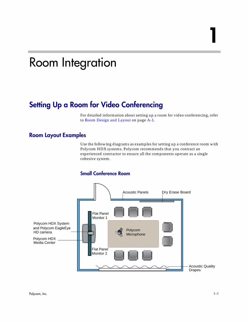
Room Layout ExamplesUse the following diagrams as examples for setting up a conference room with Polycom HDX systems. Polycom recommends that you contract an experienced contractor to ensure all the components operate as a single cohesive system.
Small Conference Room
and Polycom EagleEye Polycom
Acoustic Panels
Acoustic QualityDrapes
Dry Erase Board
Microphone
Polycom HDX System
HD camera
Flat PanelMonitor 1
Flat PanelMonitor 2
Polycom HDXMedia Center

Integrator’s Reference Manual for Polycom HDX Systems
1–2 Polycom, Inc.
Large Conference Room
SoundStation IP 7000
Document Camera
Polycom
Power OutletsNetwork Outlets
Flat PanelFlat Panel
Polycom HDX system
Acoustic Panels
Monitor 1Monitor 2
Polycom HDX
Microphone
and EagleEye HD camera
Media Center
Polycom SoundStation®IP 7000 Phone

Room Integration
Polycom, Inc. 1–3
Classroom
Setting Up the Room for Polycom People On Content™For the best results, follow these guidelines for setting up Polycom People On Content™:
• Use the Polycom EagleEye HD camera with Polycom HDX 9000 series and Polycom HDX 8000 series systems. Polycom recommends using a Polycom EagleEye II, Polycom EagleEye III, Polycom EagleEye HD or Polycom EagleEye HD 1080 camera with People on Content. If you are using a Polycom EagleEye 1080 or Polycom EagleEye View camera, activating People on Content automatically reduces the resolution to 720p.
• Create a flat, consistent background color using a screen or matte-finish paint in green or blue. Make sure the background has no shadows or glare.
Computer
Document
Monitor 1
Monitor for
Polycom
Camera 2
Table-Top Microphones
Teacher’s
Monitor 2
Touch Panel
VGA Out
Podium
Camera
HDX systemwith EagleEyeHD cameraand Polycom SoundStructure™mixer

Integrator’s Reference Manual for Polycom HDX Systems
1–4 Polycom, Inc.
• Make sure that the background and the presenter are well lit. For example, use a minimum of two 250 W halogen lights on the background and one on the presenter.
• Experiment with different room and lighting arrangements until the best results are achieved.
You can find more information about configuring and using People On Content in the User’s Guide for Polycom HDX Systems and in the Knowledge Base on the Polycom web site.
Polycom HDX Installation PrecautionsIf you place the Polycom HDX series system in a cart or credenza, ensure that there is proper ventilation for maintaining an ambient temperature of 40°C or lower.Polycom recommends ventilation gaps of at least 2 inches (50.80 mm) on the left and right of the system with appropriate access to fresh air.
3 ft
250 W
250 W
250 W
Polycom HDXsystem andEagleEye HDcamera
2” 2”

Room Integration
Polycom, Inc. 1–5
Integrating VideoThe following sections describe how to connect cameras to Polycom HDX systems. After you connect a camera to a Polycom HDX system, refer to the Administrator’s Guide for Polycom HDX Systems for information about configuring the camera options in the user interface.
Connecting Polycom CamerasYou can connect Polycom HDX systems to a Polycom EagleEye 1080, Polycom EagleEye HD, Polycom EagleEye View, Polycom EagleEye II, Polycom EagleEye III, Polycom EagleEye Director, Polycom PowerCam™, or PowerCam Plus camera from Polycom, or to other supported cameras. Refer to the release notes for the software release installed on the Polycom HDX system for a list of supported PTZ cameras.
Polycom EagleEye HD Camera as the Main Camera up to 30 ft Away
You can connect a Polycom EagleEye HD camera (part number 8200-23600-001 8200-23610-001, 8200-08270-xxx, or 8200-08260-xxx) to a Polycom HDX 9000 Series system as the main camera using:
• HDCI Analog Camera Cable on page 2-27.
Points to Note about Polycom Cameras:• The Polycom EagleEye HD connection diagrams can be applied to Polycom
EagleEye II cameras on Polycom HDX 9006 systems only. The diagrams can also be applied to EagleEye III cameras on all Polycom HDX 9000 series systems.
• Polycom HDX 6000 series, Polycom HDX 7000 series, and Polycom HDX 8000 series systems must be connected to one of the Polycom EagleEye cameras to receive signals from the remote control. Point the remote control at the camera to control those Polycom HDX systems.
1
1

Integrator’s Reference Manual for Polycom HDX Systems
1–6 Polycom, Inc.
Polycom EagleEye HD Camera as the Second Camera up to 30 ft Away
You can connect a Polycom EagleEye HD camera (part number 8200-23600-001, 8200-23610-001, 8200-08270-xxx, or 8200-08260-xxx) to a Polycom HDX 9000 Series system as the second camera using:
• HDCI Analog Camera Cable on page 2-27.
• Power supply. Use only the approved power supply from Polycom (part number 1465-52748-040). Do not exceed 12 Volts at 3 Amps. Verify the polarity of the power supply as shown on the Polycom camera next to the power supply input.
22
DC IN 12V
Use Polycom Power Supply OnlyPart Number: 1465-52733-040

Room Integration
Polycom, Inc. 1–7
Polycom EagleEye HD Camera as the Main or Second Camera up to 100 ft Away
To connect a Polycom EagleEye HD camera (part number 8200-23600-001 8200-23610-001, 8200-08270-xxx, 8200-08260-xxx, or 7200-25689-xxx) to a Polycom HDX 9000 Series system more than 30 ft away:
Option 1
• HDCI Analog Camera Cable on page 2-27.
• Power supply. Use only the approved power supply from Polycom (part number 1465-52748-040). Do not exceed 12 Volts at 3 Amps. Verify the polarity of the power supply as shown on the Polycom camera next to the power supply input.
Polycom recommends this configuration when a custom cable length is not required.
50 ft or 100 ftDC IN 12V
Use Polycom Power Supply OnlyPart Number: 1465-52733-040

Integrator’s Reference Manual for Polycom HDX Systems
1–8 Polycom, Inc.
Option 2
• A—Two HDCI Camera Break-Out Cable on page 2-30.
• B—Coaxial analog video cables.
• C—DB-9 serial cable.
• Power supply. Use only the approved power supply from Polycom (part number 1465-52748-040). Do not exceed 12 Volts at 3 Amps. Verify the polarity of the power supply as shown on the Polycom camera next to the power supply input.
Polycom recommends this configuration when a custom cable length is required. The BNC and serial cables can be built to custom lengths.
Optional, up to 100 ft
AA
B
C
DC IN 12V
Use Polycom Power Supply Only
Part Number: 1465-52733-040
Room Integration
Polycom, Inc. 1–9
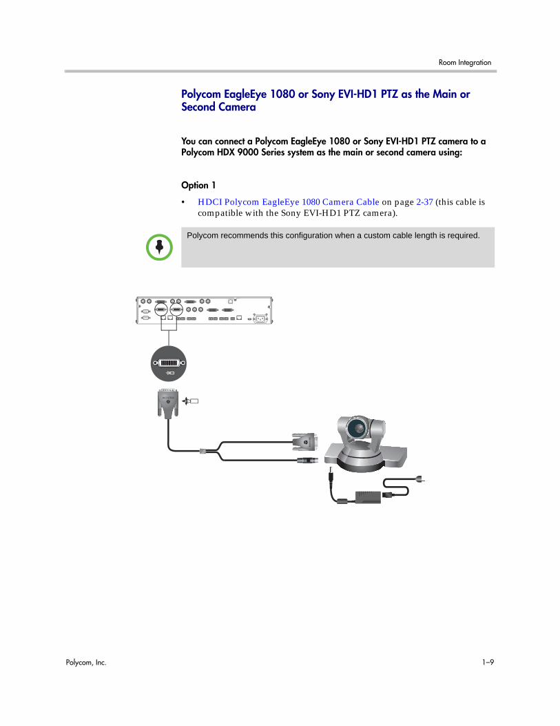
Polycom EagleEye 1080 or Sony EVI-HD1 PTZ as the Main or Second Camera
You can connect a Polycom EagleEye 1080 or Sony EVI-HD1 PTZ camera to a Polycom HDX 9000 Series system as the main or second camera using:
Option 1
• HDCI Polycom EagleEye 1080 Camera Cable on page 2-37 (this cable is compatible with the Sony EVI-HD1 PTZ camera).
Polycom recommends this configuration when a custom cable length is required.
Integrator’s Reference Manual for Polycom HDX Systems
1–10 Polycom, Inc.
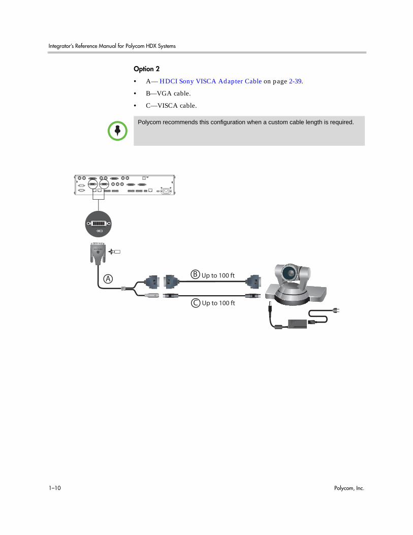
Option 2
• A— HDCI Sony VISCA Adapter Cable on page 2-39.
• B—VGA cable.
• C—VISCA cable.
Polycom recommends this configuration when a custom cable length is required.
Up to 100 ft
C
AB
Up to 100 ft
Room Integration
Polycom, Inc. 1–11
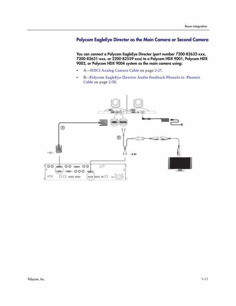
Polycom EagleEye Director as the Main Camera or Second Camera
You can connect a Polycom EagleEye Director (part number 7200-82632-xxx, 7200-82631-xxx, or 2200-82559-xxx) to a Polycom HDX 9001, Polycom HDX 9002, or Polycom HDX 9004 system as the main camera using:
• A—HDCI Analog Camera Cable on page 2-27.
• B—Polycom EagleEye Director Audio Feedback Phoenix to Phoenix Cable on page 2-59.
A
B

Integrator’s Reference Manual for Polycom HDX Systems
1–12 Polycom, Inc.
PowerCam as the Main Camera up to 10 ft Away
You can connect a PowerCam (part number 2215-50370-001) to a Polycom HDX 9001, Polycom HDX 9002, or Polycom HDX 9004 system as the main camera up to 10 ft away using:
Option 1
• HDCI PowerCam Cable on page 2-34.
Option 2
• A—PowerCam Primary Camera Cable on page 2-41.
• B— HDCI PowerCam Plus Adapter Cable on page 2-35.
1
1
1
1
A
B

Room Integration
Polycom, Inc. 1–13
PowerCam as the Second CameraThe following kits are available, which include the power supply, PowerCam Break-Out cable, 8-pin mini-DIN to DB-9 cable, and S-Video cable:
• 7230-22231-001 (50 ft)
• 7230-22232-001 (100 ft)
You can connect a PowerCam (part number 2215-50370-001) to a Polycom HDX 9001, Polycom HDX 9002, or Polycom HDX 9004 system as the second camera using:
• A— PowerCam Break-Out Cable on page 2-42.
• B— 8-pin mini-DIN to DB-9 on page 2-44.
• C— S-Video Cable on page 2-16.
• D— HDCI PowerCam Plus Adapter Cable on page 2-35.
• Power Supply (part number 1465-52748-040).
You can connect a PowerCam (part number 2215-50370-001) to a Polycom HDX 9001, Polycom HDX 9002, or Polycom HDX 9004 system as the third camera using:
• A— PowerCam Break-Out Cable on page 2-42.
• B— 8-pin mini-DIN to DB-9 on page 2-44.
• C— S-Video Cable on page 2-16.
22
A
B C
D

Integrator’s Reference Manual for Polycom HDX Systems
1–14 Polycom, Inc.
• D—BNC to S-Video Cable on page 2-17.
• Power Supply (part number 1465-52748-040).
If you connect a PTZ camera to a serial port, set RS-232 Mode to Camera PTZ on the Serial Ports screen.
IOIOIO
VCR/DVD3 IOIOIO
VCR/DVD3 Y C
B C
A
D

Room Integration
Polycom, Inc. 1–15
PowerCam Plus as the Main Camera up to 10 ft Away
You can connect a PowerCam Plus (part number 2215-50200-001) to a Polycom HDX 9001, Polycom HDX 9002, or Polycom HDX 9004 system as the main camera up to 10 ft away using:
• A— PowerCam Plus Primary Cable on page 2-33.
• B— HDCI PowerCam Plus Adapter Cable on page 2-35.
Automatic camera tracking is not available when using the PowerCam Plus camera with a Polycom HDX system.
1 1
B
A
Integrator’s Reference Manual for Polycom HDX Systems
1–16 Polycom, Inc.
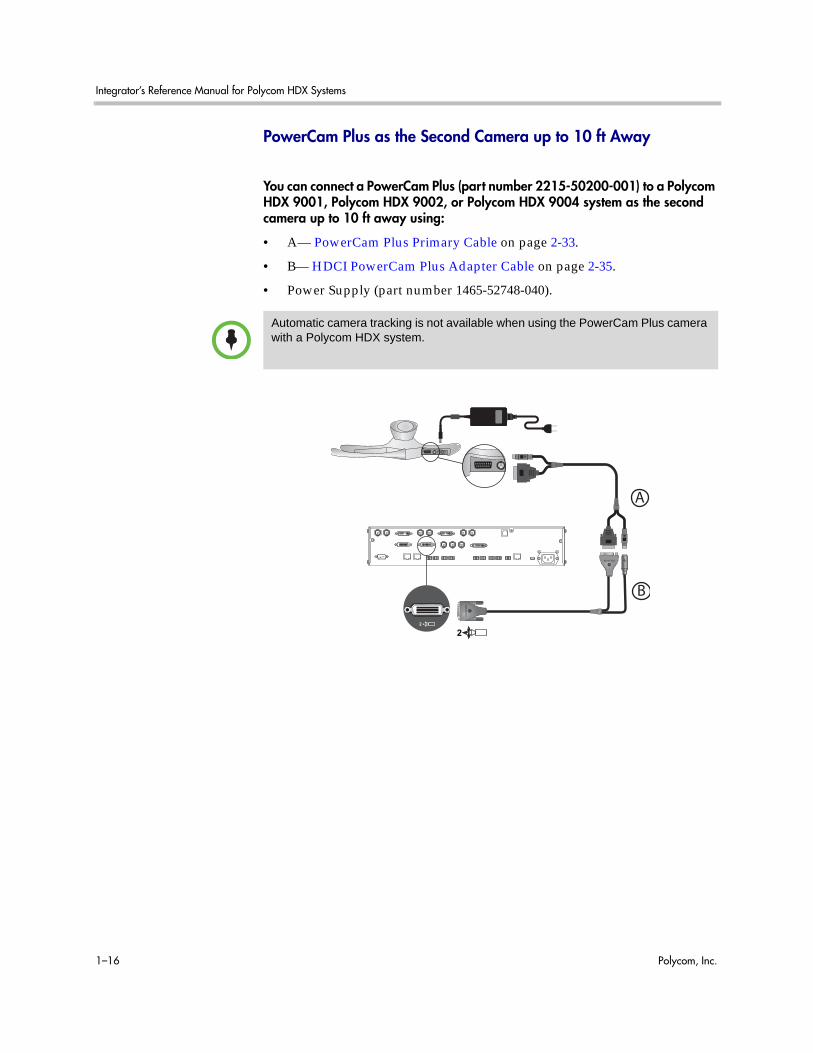
PowerCam Plus as the Second Camera up to 10 ft Away
You can connect a PowerCam Plus (part number 2215-50200-001) to a Polycom HDX 9001, Polycom HDX 9002, or Polycom HDX 9004 system as the second camera up to 10 ft away using:
• A— PowerCam Plus Primary Cable on page 2-33.
• B— HDCI PowerCam Plus Adapter Cable on page 2-35.
• Power Supply (part number 1465-52748-040).
Automatic camera tracking is not available when using the PowerCam Plus camera with a Polycom HDX system.
B
A
2
2

Room Integration
Polycom, Inc. 1–17
Connecting Sony and ELMO CamerasRefer to the release notes for a list of supported Pan/Tilt/Zoom (PTZ) cameras.
Sony or ELMO PTZ as the Main or Second Camera
To connect a Sony or ELMO PTZ camera to a Polycom HDX 9000 Series system as the main or second camera:
You can connect a Sony or ELMO PTZ camera to a Polycom HDX system using:
• A— HDCI Sony VISCA Adapter Cable on page 2-39.
• B— S-Video Cable on page 2-16.
• C—Sony VISCA cable.
Up to 100 ft
A
B
C

Integrator’s Reference Manual for Polycom HDX Systems
1–18 Polycom, Inc.
Sony BRC-H700 PTZ
To connect a Sony BRC-H700 PTZ camera to a Polycom HDX 9000 Series system:
You can connect a Sony BRC-H700 PTZ camera to a Polycom HDX system using:
• A— DVI to VGA Monitor Cable on page 2-20.
• B— 8-pin mini-DIN to DB-9 on page 2-44.
• C—VGA extension cable.
To provide XGA output (1024x768), you must install the optional Sony HFBK-XG1 card into the slot on the back of the Sony BRC-H700 PTZ camera.
Up to 100 ftA
B
C
IOIOIO
IOIOIO
Another option is to use a VGA cable for cable C and to use a VGA/DVI-A adapter (part number 1517-52689-001) for cable A. The VGA/DVI-A adapter is a solid overmolded adapter that connects to the Polycom HDX 9000 Series system side of cable C and adapts from cable C’s VGA connector to a DVI-A connector to plug into the Polycom HDX 9000 Series system.

Room Integration
Polycom, Inc. 1–19
Connecting Vaddio and Canon CamerasRefer to the release notes for a list of supported Pan/Tilt/Zoom (PTZ) cameras.
Vaddio or Canon PTZ as the Main or Second Camera
To connect a Vaddio or Canon PTZ camera to a Polycom HDX 9000 Series system as the main or second camera:
You can connect a Vaddio 70, Vaddio 100, or Canon (with VISCA cable shoe) PTZ camera to a Polycom HDX system using:
• A— HDCI VISCA Adapter Cable on page 2-36.
• B—DB-9 serial cable.
• C—S-Video Cable on page 2-16.
Up to 100 ft
A
B
C Up to 100 ft
A separate power supply is required regardless of which connector is used on the HDX 9000 Series back panel.

Integrator’s Reference Manual for Polycom HDX Systems
1–20 Polycom, Inc.
Vaddio 300 PTZ as the Main or Second Camera
To connect a Vaddio 300 PTZ camera to a Polycom HDX 9000 Series system as the main or second camera:
You can connect a Vaddio 300 PTZ camera to a Polycom HDX system using:
• A—HDCI VISCA Adapter Cable on page 2-36.
• B—DB-9 serial cable.
• C—S-Video Cable on page 2-16.
Note: For situations that require extraordinary cable lengths, CAT5 extension kits for camera video, power, and control are available from third-party vendors.
Up to 100 ft
Quick-ConnectBox
RJ45
A
B
C
Room Integration
Polycom, Inc. 1–21
Integrating Audio and Content
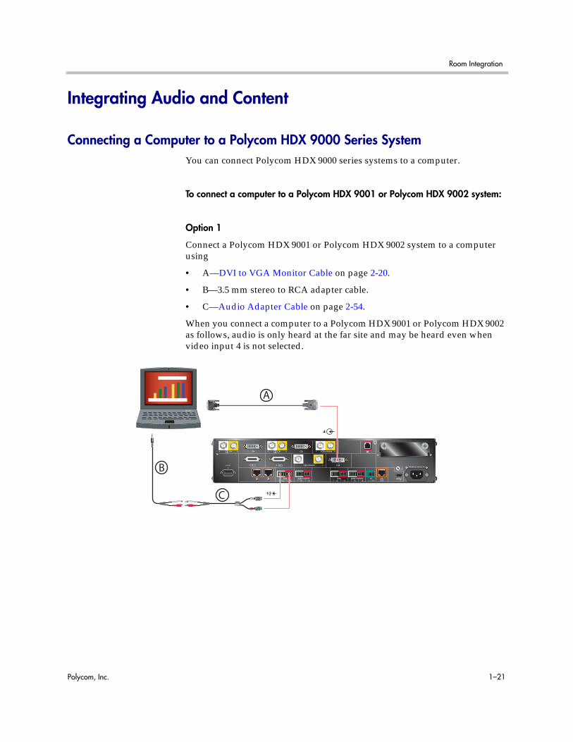
Connecting a Computer to a Polycom HDX 9000 Series SystemYou can connect Polycom HDX 9000 series systems to a computer.
To connect a computer to a Polycom HDX 9001 or Polycom HDX 9002 system:
Option 1
Connect a Polycom HDX 9001 or Polycom HDX 9002 system to a computer using
• A—DVI to VGA Monitor Cable on page 2-20.
• B—3.5 mm stereo to RCA adapter cable.
• C—Audio Adapter Cable on page 2-54.
When you connect a computer to a Polycom HDX 9001 or Polycom HDX 9002 as follows, audio is only heard at the far site and may be heard even when video input 4 is not selected.
4
2 1
100-240VAC 50/60Hz 4A
LAN IR 3 VCR/DVD 1
4
Y C 3 VCR/DVD
Y C VCR/DVD 3
3 VCR/DVD 1
2
Y C
1
1
IOIOIO
Y C
1
A
B
C

Integrator’s Reference Manual for Polycom HDX Systems
1–22 Polycom, Inc.
Option 2
To hear audio at both the near site and the far site, use a bypass mixer to connect a computer to the Polycom HDX 9001 or Polycom HDX 9002 system as the following figure shows.
4
2 1
100-240VAC 50/60Hz 4A
LANIR3 VCR/DVD1
4
Y C3 VCR/DVD
Y CVCR/DVD3
3 VCR/DVD1
2
Y C
1
1
IOIOIO
Y C
1
1

Room Integration
Polycom, Inc. 1–23
To connect a computer to a Polycom HDX 9004 system:
Connect a Polycom HDX 9004 system to a computer using
• A—DVI to VGA Monitor Cable on page 2-20.
• B—3.5 mm stereo to RCA adapter cable.
• C—Audio Adapter Cable on page 2-54 (Polycom HDX 9004, Polycom HDX 9002, and Polycom HDX 9001 systems only).
When you connect a computer to video input 4 and audio input 4 on a Polycom HDX 9004 as follows, audio from input 4 is muted unless video input 4 is selected as a video source.
2 1
100-240VAC 50/60Hz 4A
LAN IR
5
4
3 VCR/DVD 1
4
Y C 3 VCR/DVD
Y C VCR/DVD 3
4 3 VCR/DVD 1
2
Y C
1
2
1
IOIOIO
Y C
4
4
A
C
B
Integrator’s Reference Manual for Polycom HDX Systems
1–24 Polycom, Inc.
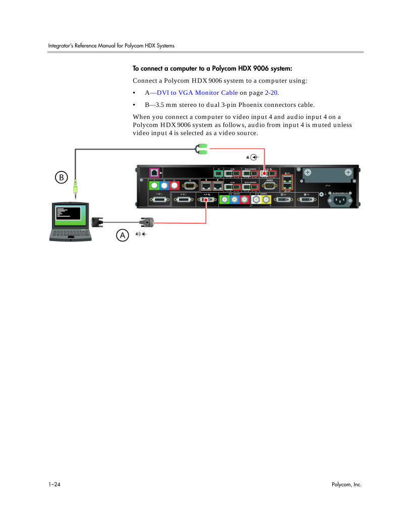
To connect a computer to a Polycom HDX 9006 system:
Connect a Polycom HDX 9006 system to a computer using:
• A—DVI to VGA Monitor Cable on page 2-20.
• B—3.5 mm stereo to dual 3-pin Phoenix connectors cable.
When you connect a computer to video input 4 and audio input 4 on a Polycom HDX 9006 system as follows, audio from input 4 is muted unless video input 4 is selected as a video source.

Room Integration
Polycom, Inc. 1–25
Connecting a Vortex® Mixer to a Polycom HDX 9000 Series System
Connect a Polycom HDX system to the Vortex mixer using:
• Vortex cable shown on page Vortex Cable on page 2-56.
Polycom strongly recommends using Polycom InstantDesigner™ to get started with your Vortex® mixer integration. InstantDesigner resolves many common issues with connections and configuration settings.
To use a Polycom HDX system with audio input from a Vortex mixer, set the Input Type to Line Input and disable Echo Canceller.
IOIOIO
A B
A B
2 1
100-240VAC 50/60Hz 4A
LANIR
5
4
3 VCR/DVD1
4
Y C3 VCR/DVD
Y CVCR/DVD3
4 3 VCR/DVD1
2
Y C
1
2
1
IOIOIO
Y C
1 1

Integrator’s Reference Manual for Polycom HDX Systems
1–26 Polycom, Inc.
Connecting a Polycom SoundStructure C-Series Mixer to a Polycom HDX 9000 Series System
Connect a Polycom HDX system to the Polycom SoundStructure C-Series mixer using:
• Polycom HDX Microphone Host Cable on page 2-46.
2 1
100-240VAC 50/60Hz 4A
LANIR
5
4
3 VCR/DVD1
4
Y C3 VCR/DVD
Y CVCR/DVD3
4 3 VCR/DVD1
2
Y C
1
2
1
IOIOIO
Y C
C
AV 0
52-0
9z
H 06
/05
PIN 2: TXDPIN 3: RXDPIN 5: GROUNDPIN 7: CTSPIN 8: RTS
LAN C-LINK2 OBAM IR
RS-232
REMOTE CONTROL 2
REMOTE CONTROL 1
IN OUT
1 2 3 4 5 6 7 8 9 10 11 12 13 14 15 16
1 2 3 4 5 6 7 8 9 10 11 12 13 14 15 16
STUP
TU
OST
UPN I
SoundStructure C16TM12V
Points to Note:• The microphone input of the Polycom HDX 9000 Series system can support one
SoundStructure C-Series mixer that has up to four Polycom HDX microphones connected to it. For more information about using the SoundStructure C-Series mixer with a Polycom HDX system, refer to the SoundStructure C-Series documentation on the Polycom web site.
You cannot connect both a SoundStructure C-Series mixer and a SoundStation IP 7000 phone to the Polycom HDX 9000 Series system at the same time.
• If the EagleEye Director camera is connected to a Polycom HDX system that is connected to a SoundStructure C-Series mixer (or echo cancellers, sound mixers, or other external devices) and the SoundStructure C-Series mixer is connected to the room audio playback system, the EagleEye Director's audio feedback cable (Polycom EagleEye Director Audio Feedback Phoenix to Phoenix Cable on page 2-59) must connect to the balanced audio output connector of SoundStructure. The room audio playback system must connect through the EagleEye Director's audio feedback cable to the SoundStructure C-Series mixer.

Polycom, Inc. 2–1
2Cables
This chapter includes information about cables that can be used with a Polycom HDX system. Please note that drawings and part numbers are provided for reference only. Compliance information is provided for the Restriction of certain Hazardous Substances Directive (RoHS).
Network Cables
CAT 5e LAN CableThis cable connects a Polycom HDX system to the LAN. It has orange RJ-45 connectors on both ends. It meets category 5e requirements and is wired according to EIA/TIA-568B. The maximum approved length for this cable is 100 ft (30 m) on an 802 network.
Length Part Number RoHS Compliant
12 ft (3.6 m) 2457-23537-001 Yes
T568B PairT568B Pair

Integrator’s Reference Manual for Polycom HDX Systems
2–2 Polycom, Inc.
Drawings and part numbers are provided for reference only. Polycom claims no responsibility or liability for the quality, performance, or reliability of cables based on these reference drawings, other than cables provided by Polycom. Contact your Polycom distributor or Polycom Custom/Vertical Products to order cables that meet the appropriate manufacturing tolerances, quality, and performance parameters for your application.

Cables
Polycom, Inc. 2–3
LAN CableThis cable connects a Polycom HDX system to the LAN. It has orange RJ-45 connectors on both ends and is used with all systems. The maximum approved length for this cable is 100 ft (30 m).
Length Part Number RoHS Compliant
12 ft (3.6 m) 2457-08343-001 Yes
Drawings and part numbers are provided for reference only. Polycom claims no responsibility or liability for the quality, performance, or reliability of cables based on these reference drawings, other than cables provided by Polycom. Contact your Polycom distributor or Polycom Custom/Vertical Products to order cables that meet the appropriate manufacturing tolerances, quality, and performance parameters for your application.
CONN. RJ-45( x2 )
12 FEET +/- 3"
P2P1
PIN 8 PIN 8
1 1
22
33
44
55
66
77
88
PIN#
PIN#
P2P1
Integrator’s Reference Manual for Polycom HDX Systems
2–4 Polycom, Inc.
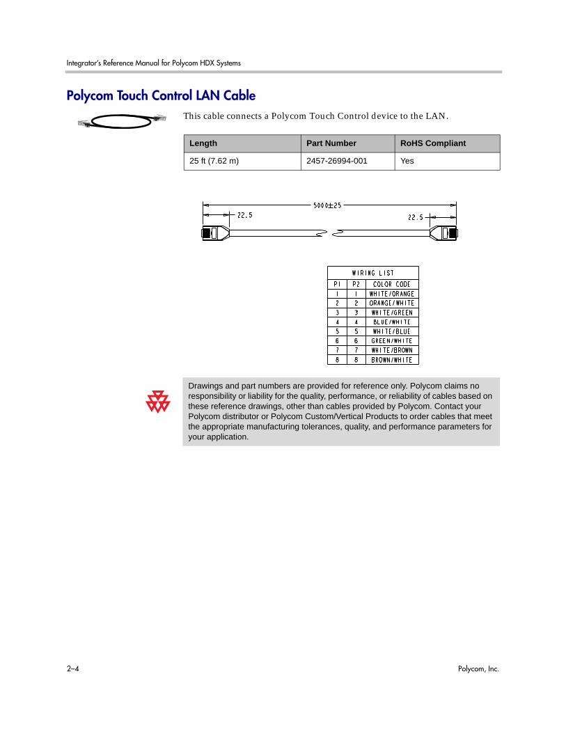
Polycom Touch Control LAN CableThis cable connects a Polycom Touch Control device to the LAN.
Length Part Number RoHS Compliant
25 ft (7.62 m) 2457-26994-001 Yes
Drawings and part numbers are provided for reference only. Polycom claims no responsibility or liability for the quality, performance, or reliability of cables based on these reference drawings, other than cables provided by Polycom. Contact your Polycom distributor or Polycom Custom/Vertical Products to order cables that meet the appropriate manufacturing tolerances, quality, and performance parameters for your application.
Cables
Polycom, Inc. 2–5
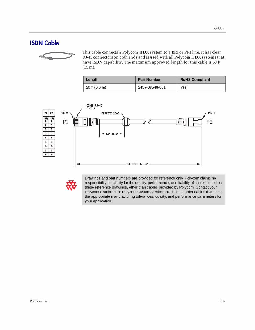
ISDN CableThis cable connects a Polycom HDX system to a BRI or PRI line. It has clear RJ-45 connectors on both ends and is used with all Polycom HDX systems that have ISDN capability. The maximum approved length for this cable is 50 ft (15 m).
Length Part Number RoHS Compliant
20 ft (6.6 m) 2457-08548-001 Yes
Drawings and part numbers are provided for reference only. Polycom claims no responsibility or liability for the quality, performance, or reliability of cables based on these reference drawings, other than cables provided by Polycom. Contact your Polycom distributor or Polycom Custom/Vertical Products to order cables that meet the appropriate manufacturing tolerances, quality, and performance parameters for your application.

Integrator’s Reference Manual for Polycom HDX Systems
2–6 Polycom, Inc.
PRI Pin AssignmentsThe following illustration and table show the pin assignments for the PRI port on the Polycom HDX system.
Pin 8
Pin 1
Signal Name
Receive Ring
Receive Tip
No Connection
Transmit Ring
Transmit Tip
No Connection
No Connection
No Connection
Pin
1
2
3
4
5
6
7
8

Cables
Polycom, Inc. 2–7
Analog Telephone (POTS) CableThis cable connects a Polycom HDX system to an analog telephone line. It has pink RJ-11 connectors on both ends. The maximum approved length for this cable is 100 ft (30 m).
Length Part Number RoHS Compliant
12 ft (3.6 m) 2457-20071-001 Yes
Drawings and part numbers are provided for reference only. Polycom claims no responsibility or liability for the quality, performance, or reliability of cables based on these reference drawings, other than cables provided by Polycom. Contact your Polycom distributor or Polycom Custom/Vertical Products to order cables that meet the appropriate manufacturing tolerances, quality, and performance parameters for your application.

Integrator’s Reference Manual for Polycom HDX Systems
2–8 Polycom, Inc.
V.35/RS-449/RS-530 Serial AdapterThis adapter is used when connecting a Polycom HDX system to other third-party network equipment. It adapts the 68-pin interface to an industry standard 44-pin interface used by some network interface equipment. It is used with Polycom HDX systems that have a V.35/RS-449/RS-530 serial network interface card (NIC) installed.
Length Part Number RoHS Compliant
6 in (15.23 cm) 2457-21264-200 Yes
Drawings and part numbers are provided for reference only. Polycom claims no responsibility or liability for the quality, performance, or reliability of cables based on these reference drawings, other than cables provided by Polycom. Contact your Polycom distributor or Polycom Custom/Vertical Products to order cables that meet the appropriate manufacturing tolerances, quality, and performance parameters for your application.
Notes (direction from V.35 module (DTE))68 pin Signal Name Signal Type From card Function V.35 RS530-DB25 RS4449-DB37 RS366-DB25
Shield V.35/RS449/RS530 A 19 7,18,19#
12 Receive Data A Differential in V.35/RS449/RS530 R 3 6
11 Receive Data B Differential in V.35/RS449/RS530 T 16 24
10 Send Timing A Differential in V.35/RS449/RS530 Y 15 5
9 Send Timing B Differential in V.35/RS449/RS530 AA 12 23
29 Data Set Ready (DSR) Single Ended in V.35 E
28 Request To Send (RTS) Single Ended out V.35 C
27 Data Terminal Ready (DTR) Single Ended out V.35 H
34 Digit Present (DPR) Single Ended out RS366 2
24 Abandon Call/Retry (ACR) Single Ended in RS366 3
32 Call Request (CRQ) Single Ended out RS366 4
26 Present Next Digit (PND) Single Ended in RS366 5
21 Data Line Occupied (DLO) Single Ended in RS366 22
14 Receive Timing A Differential in V.35/RS449/RS530 V 17 8
13 Receive Timing B Differential in V.35/RS449/RS530 X 9 26
8 Terminal Timing A Differential out V.35/RS449/RS530 U 24 17
7 Terminal Timing B Differential out V.35/RS449/RS530 W 11 35
15 Request To Send (RTS) A Differential out RS449/RS530 4 7
16 Request To Send (RTS) B Differential out RS449/RS530 19 25
35** Receive Common Gnd RS449 20
20 BCD Dial Digit Bit 1 (NB1) Single Ended out RS366 14
19 BCD Dial Digit Bit 2 (NB2) Single Ended out RS366 15
23 BCD Dial Digit Bit 4 (NB4) Single Ended out RS366 16
25 BCD Dial Digit Bit 8 (NB8) Single Ended out RS366 17
2** Signal Ground Gnd V.35/RS366 B 7,18,19
6 Send Data A Differential out V.35/RS449/RS530 P 2 4
5 Send Data B Differential out V.35/RS449/RS530 S 14 22
reserved (Ascend select line)
63 Clear To Send (CTS) A Differential in RS449/RS530 5 9
64 Clear To Send (CTS) B Differential in RS449/RS530 13 27
61 Data Mode (DM-DSR) A Differential in RS449/RS530 6 11
62 Data Mode (DM-DSR) B Differential in RS449/RS530 22 29
65 Receiver Ready (RR-DCD) A Differential in RS449/RS530 8 13
66 Receiver Ready (RR-DCD) B Differential in RS449/RS530 10 31
4** Send Common Gnd RS530 7 37
33 Data Carrier Detect (DCD) Single Ended in V.35 F
18 Terminal Ready (TR-DTR) A Differential out RS449/RS530 20 12
17 Terminal Ready (TR-DTR) B Differential out RS449/RS530 23 30
3 V.35 Cable Connected ground to indicate a V.35 cable is attached 7,18,19*
1 RS449 Cable Connected ground to indicate a RS449 cable is attached 7,18,19^#
22 Distant Station Connected (DSC) Single Ended in RS366 13
30 Clear To Send (CTS) Single Ended in V.35 D
31 Ring Indicate (RI) (Incoming Call)Single Ended in V.35/RS449 J 15
reserved (Ascend select line)
68 LOS A Differential out RS530 crypto 18 3
67 LOS B Differential out RS530 crypto 21 21
* For V.35, connect pin 3 of 68 pin connector to ground
^For RS449, connect pin 1 of 68 pin connector to ground
#For RS530, connect pins 1 and 3 of 68 pin connector to ground
** Gnd pins are 2,4, 35-60
Peripheral Link V.35 HD-68 Pinout
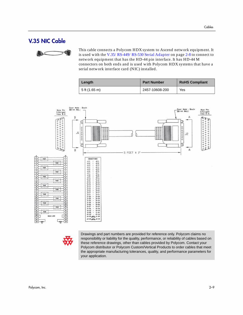
Cables
Polycom, Inc. 2–9
V.35 NIC CableThis cable connects a Polycom HDX system to Ascend network equipment. It is used with the V.35/RS-449/RS-530 Serial Adapter on page 2-8 to connect to network equipment that has the HD-44 pin interface. It has HD-44 M connectors on both ends and is used with Polycom HDX systems that have a serial network interface card (NIC) installed.
Length Part Number RoHS Compliant
5 ft (1.65 m) 2457-10608-200 Yes
Drawings and part numbers are provided for reference only. Polycom claims no responsibility or liability for the quality, performance, or reliability of cables based on these reference drawings, other than cables provided by Polycom. Contact your Polycom distributor or Polycom Custom/Vertical Products to order cables that meet the appropriate manufacturing tolerances, quality, and performance parameters for your application.

Integrator’s Reference Manual for Polycom HDX Systems
2–10 Polycom, Inc.
V.35 and RS-366 Serial CableThis cable connects a Polycom HDX system to third-party network equipment. It is used with the V.35/RS-449/RS-530 Serial Adapter on page 2-8 to connect to network equipment that has a V.35/RS-366 interface. It is HD-44 M to “Y” Winchester 34M/RS-366 DB-25M and is used with Polycom HDX systems that have a serial network interface card (NIC) installed.
Length Part Number RoHS Compliant
5 ft (1.65 m) 2457-10609-200 Yes
Drawings and part numbers are provided for reference only. Polycom claims no responsibility or liability for the quality, performance, or reliability of cables based on these reference drawings, other than cables provided by Polycom. Contact your Polycom distributor or Polycom Custom/Vertical Products to order cables that meet the appropriate manufacturing tolerances, quality, and performance parameters for your application.
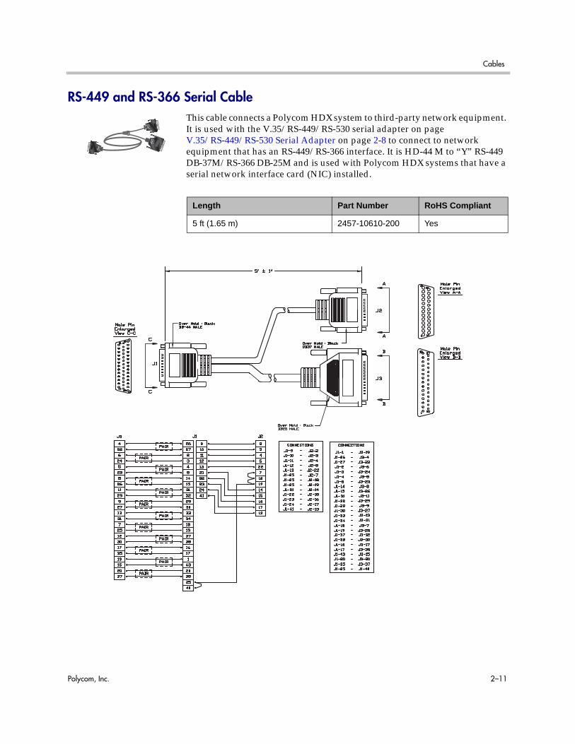
Cables
Polycom, Inc. 2–11
RS-449 and RS-366 Serial CableThis cable connects a Polycom HDX system to third-party network equipment. It is used with the V.35/RS-449/RS-530 serial adapter on page V.35/RS-449/RS-530 Serial Adapter on page 2-8 to connect to network equipment that has an RS-449/RS-366 interface. It is HD-44 M to “Y” RS-449 DB-37M/RS-366 DB-25M and is used with Polycom HDX systems that have a serial network interface card (NIC) installed.
Length Part Number RoHS Compliant
5 ft (1.65 m) 2457-10610-200 Yes
Integrator’s Reference Manual for Polycom HDX Systems
2–12 Polycom, Inc.
Drawings and part numbers are provided for reference only. Polycom claims no responsibility or liability for the quality, performance, or reliability of cables based on these reference drawings, other than cables provided by Polycom. Contact your Polycom distributor or Polycom Custom/Vertical Products to order cables that meet the appropriate manufacturing tolerances, quality, and performance parameters for your application.

Cables
Polycom, Inc. 2–13
RS-530 with RS-366 Serial CableThis cable connects a Polycom HDX system to third-party network equipment. It is used with the V.35/RS-449/RS-530 Serial Adapter on page 2-8 to connect to network equipment that has an RS-530/RS-366 interface. It is HD-68M to “Y” DB-25M and is used with Polycom HDX systems that have a serial network interface card (NIC) installed.
Length Part Number RoHS Compliant
5 ft (1.65 m) 2457-21263-200 Yes
Peripheral Link V.35 HD-68 Pinout Notes (direction from V.35 module (DTE))68 pin Signal Name Signal Type From card Function RS530-DB25 RS366-DB25
Shield V.35/RS449/RS530 7,18,19#12 Receive Data A Differential in V.35/RS449/RS530 311 Receive Data B Differential in V.35/RS449/RS530 1610 Send Timing A Differential in V.35/RS449/RS530 159 Send Timing B Differential in V.35/RS449/RS530 1229 Data Set Ready (DSR) Single Ended in V.3528 Request To Send (RTS) Single Ended out V.3527 Data Terminal Ready (DTR) Single Ended out V.3534 Digit Present (DPR) Single Ended out RS366 224 Abandon Call/Retry (ACR) Single Ended in RS366 332 Call Request (CRQ) Single Ended out RS366 426 Present Next Digit (PND) Single Ended in RS366 521 Data Line Occupied (DLO) Single Ended in RS366 2214 Receive Timing A Differential in V.35/RS449/RS530 1713 Receive Timing B Differential in V.35/RS449/RS530 98 Terminal Timing A Differential out V.35/RS449/RS530 247 Terminal Timing B Differential out V.35/RS449/RS530 1115 Request To Send (RTS) A Differential out RS449/RS530 416 Request To Send (RTS) B Differential out RS449/RS530 19
35** Receive Common Gnd RS44920 BCD Dial Digit Bit 1 (NB1) Single Ended out RS366 1419 BCD Dial Digit Bit 2 (NB2) Single Ended out RS366 1523 BCD Dial Digit Bit 4 (NB4) Single Ended out RS366 1625 BCD Dial Digit Bit 8 (NB8) Single Ended out RS366 172** Signal Ground Gnd V.35/RS366 7,18,196 Send Data A Differential out V.35/RS449/RS530 25 Send Data B Differential out V.35/RS449/RS530 14
reserved (Ascend select line)63 Clear To Send (CTS) A Differential in RS449/RS530 564 Clear To Send (CTS) B Differential in RS449/RS530 1361 Data Mode (DM-DSR) A Differential in RS449/RS530 662 Data Mode (DM-DSR) B Differential in RS449/RS530 2265 Receiver Ready (RR-DCD) A Differential in RS449/RS530 866 Receiver Ready (RR-DCD) B Differential in RS449/RS530 104** Send Common Gnd RS530 733 Data Carrier Detect (DCD) Single Ended in V.3518 Terminal Ready (TR-DTR) A Differential out RS449/RS530 2017 Terminal Ready (TR-DTR) B Differential out RS449/RS530 233 V.35 Cable Connected ground to indicate a V.35 cable is attached 7,18,19*1 RS449 Cable Connected ground to indicate a RS449 cable is attached 7,18,19^#22 Distant Station Connected (DSC) Single Ended in RS366 1330 Clear To Send (CTS) Single Ended in V.3531 Ring Indicate (RI) (Incoming Call)Single Ended in V.35/RS449
reserved (Ascend select line)68 LOS A Differential out RS530 crypto 1867 LOS B Differential out RS530 crypto 21
* For V.35, connect pin 3 of 68 pin connector to ground^For RS449, connect pin 1 of 68 pin connector to ground#For RS530, connect pins 1 and 3 of 68 pin connector to ground** Gnd pins are 2,4, 35-60

Integrator’s Reference Manual for Polycom HDX Systems
2–14 Polycom, Inc.
Drawings and part numbers are provided for reference only. Polycom claims no responsibility or liability for the quality, performance, or reliability of cables based on these reference drawings, other than cables provided by Polycom. Contact your Polycom distributor or Polycom Custom/Vertical Products to order cables that meet the appropriate manufacturing tolerances, quality, and performance parameters for your application.

Cables
Polycom, Inc. 2–15
Polycom Touch Control Power AdapterThis adapter connects the Polycom Touch Control device to the LAN and a power supply (part number 2200-42740-XXX) for rooms that do not have Power over Ethernet (PoE).
Length Part Number RoHS Compliant
2.1 ft (.61 m) 2457-40054-001 Yes
Drawings and part numbers are provided for reference only. Polycom claims no responsibility or liability for the quality, performance, or reliability of cables based on these reference drawings, other than cables provided by Polycom. Contact your Polycom distributor or Polycom Custom/Vertical Products to order cables that meet the appropriate manufacturing tolerances, quality, and performance parameters for your application.

Integrator’s Reference Manual for Polycom HDX Systems
2–16 Polycom, Inc.
Video and Camera Cables
S-Video CableThese cables connect a Polycom HDX system to a monitor or camera. They have yellow 4-pin mini-DIN connectors on both ends and are used with all Polycom HDX systems. The maximum approved length for this cable is 200 ft (60 m).
Length Part Number RoHS Compliant
8 ft (2.4 m) 2457-08410-002 Yes
25 ft (7.6 m) 2457-08409-002 Yes
50 ft (15 m) 2457-09204-200 Yes
Drawings and part numbers are provided for reference only. Polycom claims no responsibility or liability for the quality, performance, or reliability of cables based on these reference drawings, other than cables provided by Polycom. Contact your Polycom distributor or Polycom Custom/Vertical Products to order cables that meet the appropriate manufacturing tolerances, quality, and performance parameters for your application.
P3P3 P4P4
P1P1 P2P2
25 FEET +/- 2"25 FEET +/- 2"
P3P3 P4P4
P1P1 P2P2
MINI-DIN MALE 4 POS. ( x2)MINI-DIN MALE 4 POS. ( x2)

Cables
Polycom, Inc. 2–17
BNC to S-Video CableThis cable connects S-Video devices to a Polycom HDX system. It is 4-pin male mini-DIN to dual BNC male. The maximum approved length for this cable is 100 ft (30 m).
Length Part Number RoHS Compliant
6 ft (1.8 m) 2457-21489-200 Yes
Drawings and part numbers are provided for reference only. Polycom claims no responsibility or liability for the quality, performance, or reliability of cables based on these reference drawings, other than cables provided by Polycom. Contact your Polycom distributor or Polycom Custom/Vertical Products to order cables that meet the appropriate manufacturing tolerances, quality, and performance parameters for your application.
DIMENSIONS ARE IN MILLIMETERSDIMENSIONS ARE IN MILLIMETERS

Integrator’s Reference Manual for Polycom HDX Systems
2–18 Polycom, Inc.
BNC to S-Video AdapterThis adapter may be required when connecting standard S-Video cables to a Polycom HDX system. It is dual BNC male to 4-pin female mini-DIN.
Length Part Number RoHS Compliant
1 ft (.3 m) 2457-21490-200 Yes
Drawings and part numbers are provided for reference only. Polycom claims no responsibility or liability for the quality, performance, or reliability of cables based on these reference drawings, other than cables provided by Polycom. Contact your Polycom distributor or Polycom Custom/Vertical Products to order cables that meet the appropriate manufacturing tolerances, quality, and performance parameters for your application.

Cables
Polycom, Inc. 2–19
S-Video to RCA AdapterThis adapter is used when connecting a standard composite video cable (or the video jack on a VCR cable) into an S-Video connector on a Polycom HDX system. It is yellow RCA to 4-pin mini-DIN.
This adapter can be used along with the BNC to S-Video cable (part number 2457-21489-200) or BNC to S-Video adapter (part number 2457-21490-200) to connect a composite monitor or VCR to a BNC connector on a Polycom HDX 9000 series system.
Length Part Number RoHS Compliant
1.5 in 1517-08822-002 Yes
Drawings and part numbers are provided for reference only and might not be available separately. Polycom claims no responsibility or liability for the quality, performance, or reliability of cables based on these reference drawings, other than cables provided by Polycom. Contact your Polycom distributor or Polycom Custom Products/Vertical Solutions to order cables that meet the appropriate manufacturing tolerances, quality, and performance parameters for your application.
WIRE LISTWIRE LIST
J1-SHIELD
P1-3
P1-4
P1-1
P1-SHIELD
J1-CENTER
N.C.
P1-2
N.C.
1
3
2
4
0.25” 1.00” 0.25”
S-VIDEOMALE PINS(P1)
OVERMOLDOVERPRE-SHOTAPPROX.PANTONE #109YELLOW
RCAFEMALE(J1)

Integrator’s Reference Manual for Polycom HDX Systems
2–20 Polycom, Inc.
DVI to VGA Monitor CableThis cable connects a Polycom HDX system DVI-I output to a VGA monitor. It can also be used to connect a computer to one of the DVI-A video inputs on a Polycom HDX system. It is male DVI-A to male HD-15.
Length Part Number RoHS Compliant
4 ft 6 in (1.5 m) 2457-25182-001 Yes
9 ft 10 in (3 m) 2457-23792-001 Yes
25 ft (7.6 m) 2457-23792-025 Yes
Drawings and part numbers are provided for reference only. Polycom claims no responsibility or liability for the quality, performance, or reliability of cables based on these reference drawings, other than cables provided by Polycom. Contact your Polycom distributor or Polycom Custom/Vertical Products to order cables that meet the appropriate manufacturing tolerances, quality, and performance parameters for your application.

Cables
Polycom, Inc. 2–21
HDMI Monitor CableThis cable connects the Polycom HDX system DVI-I output to an HDMI monitor. It is male DVI-D to male HDMI.
Length Part Number RoHS Compliant
9 ft 10 in (3 m) 2457-23905-001 Yes
Drawings and part numbers are provided for reference only. Polycom claims no responsibility or liability for the quality, performance, or reliability of cables based on these reference drawings, other than cables provided by Polycom. Contact your Polycom distributor or Polycom Custom/Vertical Products to order cables that meet the appropriate manufacturing tolerances, quality, and performance parameters for your application.

Integrator’s Reference Manual for Polycom HDX Systems
2–22 Polycom, Inc.
BNC Monitor Adapter CableThis cable connects the Polycom HDX system DVI-I output to a variety of analog display devices with composite, S-Video, component YPbPr, or RGBHV inputs. It is male DVI-A to five female BNC connectors.
Length Part Number RoHS Compliant
1 ft (0.3 m) 2457-23533-001 Yes
Drawings and part numbers are provided for reference only. Polycom claims no responsibility or liability for the quality, performance, or reliability of cables based on these reference drawings, other than cables provided by Polycom. Contact your Polycom distributor or Polycom Custom/Vertical Products to order cables that meet the appropriate manufacturing tolerances, quality, and performance parameters for your application.

Cables
Polycom, Inc. 2–23
Polycom HDX Component Monitor CableThis cable connects a Polycom HDX system DVI-I output to a monitor with component connections. It is male DVI-A to three RCA.
Length Part Number RoHS Compliant
6 ft (1.8 m) 2457-52698-006 Yes
12 ft (3.6 m) 2457-52698-012 Yes
Drawings and part numbers are provided for reference only. Polycom claims no responsibility or liability for the quality, performance, or reliability of cables based on these reference drawings, other than cables provided by Polycom. Contact your Polycom distributor or Polycom Custom/Vertical Products to order cables that meet the appropriate manufacturing tolerances, quality, and performance parameters for your application.
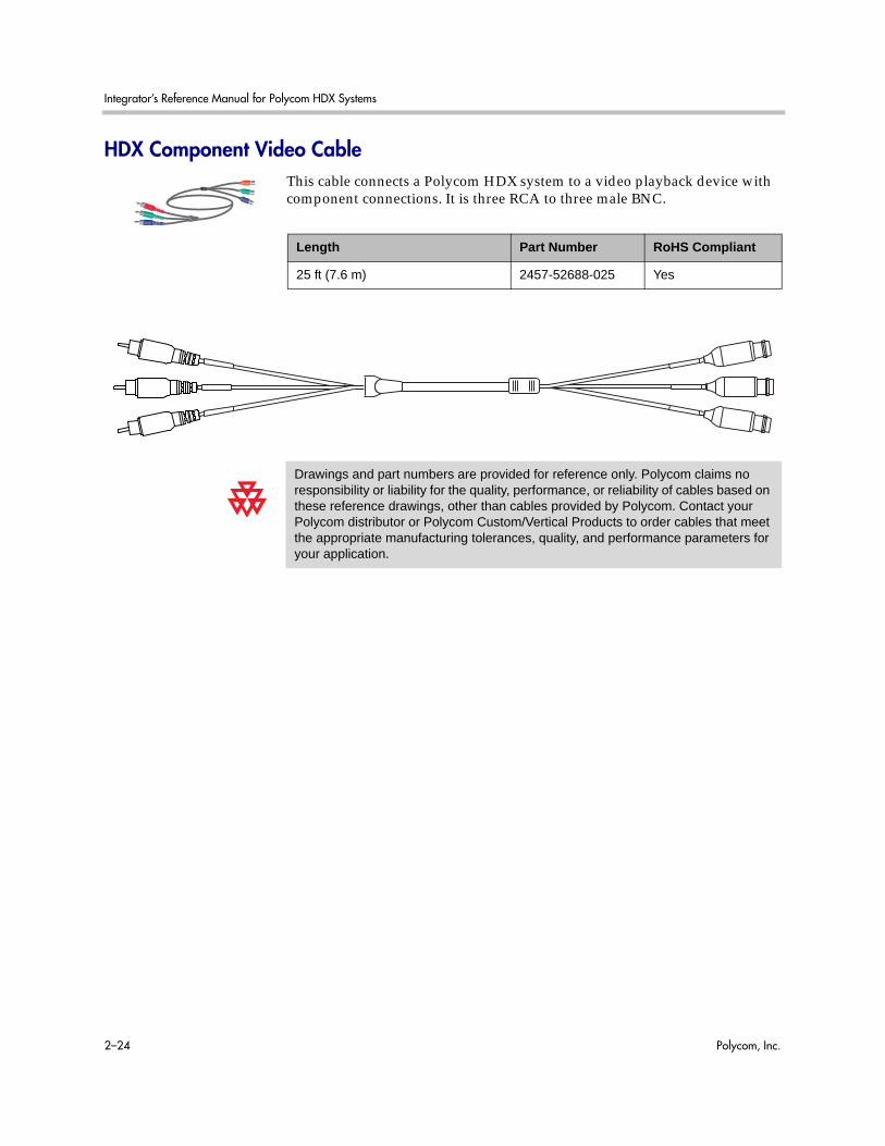
Integrator’s Reference Manual for Polycom HDX Systems
2–24 Polycom, Inc.
HDX Component Video CableThis cable connects a Polycom HDX system to a video playback device with component connections. It is three RCA to three male BNC.
Length Part Number RoHS Compliant
25 ft (7.6 m) 2457-52688-025 Yes
Drawings and part numbers are provided for reference only. Polycom claims no responsibility or liability for the quality, performance, or reliability of cables based on these reference drawings, other than cables provided by Polycom. Contact your Polycom distributor or Polycom Custom/Vertical Products to order cables that meet the appropriate manufacturing tolerances, quality, and performance parameters for your application.

Cables
Polycom, Inc. 2–25
DVI-D Monitor CableThis cable connects a Polycom HDX system DVI-I output to a DVI-D monitor. It is male DVI-D on both ends.
Length Part Number RoHS Compliant
4 ft 6 in (1.5 m) 2457-25181-001 Yes
9 ft 10 in (3 m) 2457-23793-001 Yes
Drawings and part numbers are provided for reference only. Polycom claims no responsibility or liability for the quality, performance, or reliability of cables based on these reference drawings, other than cables provided by Polycom. Contact your Polycom distributor or Polycom Custom/Vertical Products to order cables that meet the appropriate manufacturing tolerances, quality, and performance parameters for your application.
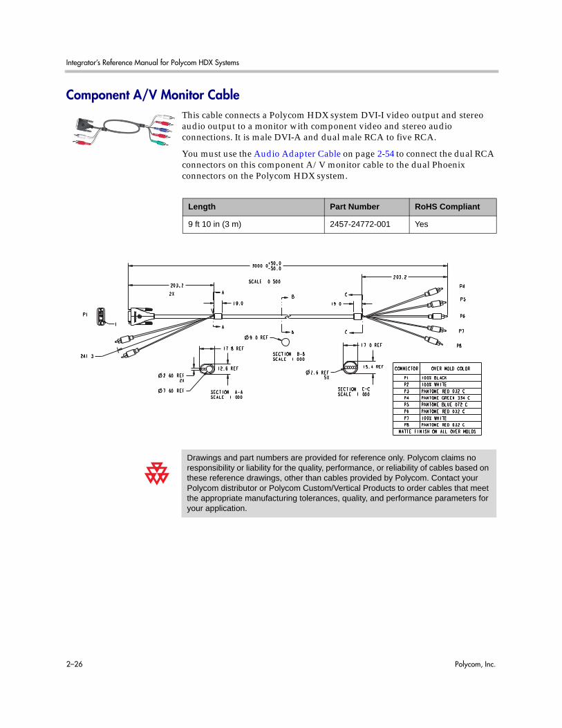
Integrator’s Reference Manual for Polycom HDX Systems
2–26 Polycom, Inc.
Component A/V Monitor CableThis cable connects a Polycom HDX system DVI-I video output and stereo audio output to a monitor with component video and stereo audio connections. It is male DVI-A and dual male RCA to five RCA.
You must use the Audio Adapter Cable on page 2-54 to connect the dual RCA connectors on this component A/V monitor cable to the dual Phoenix connectors on the Polycom HDX system.
Length Part Number RoHS Compliant
9 ft 10 in (3 m) 2457-24772-001 Yes
Drawings and part numbers are provided for reference only. Polycom claims no responsibility or liability for the quality, performance, or reliability of cables based on these reference drawings, other than cables provided by Polycom. Contact your Polycom distributor or Polycom Custom/Vertical Products to order cables that meet the appropriate manufacturing tolerances, quality, and performance parameters for your application.
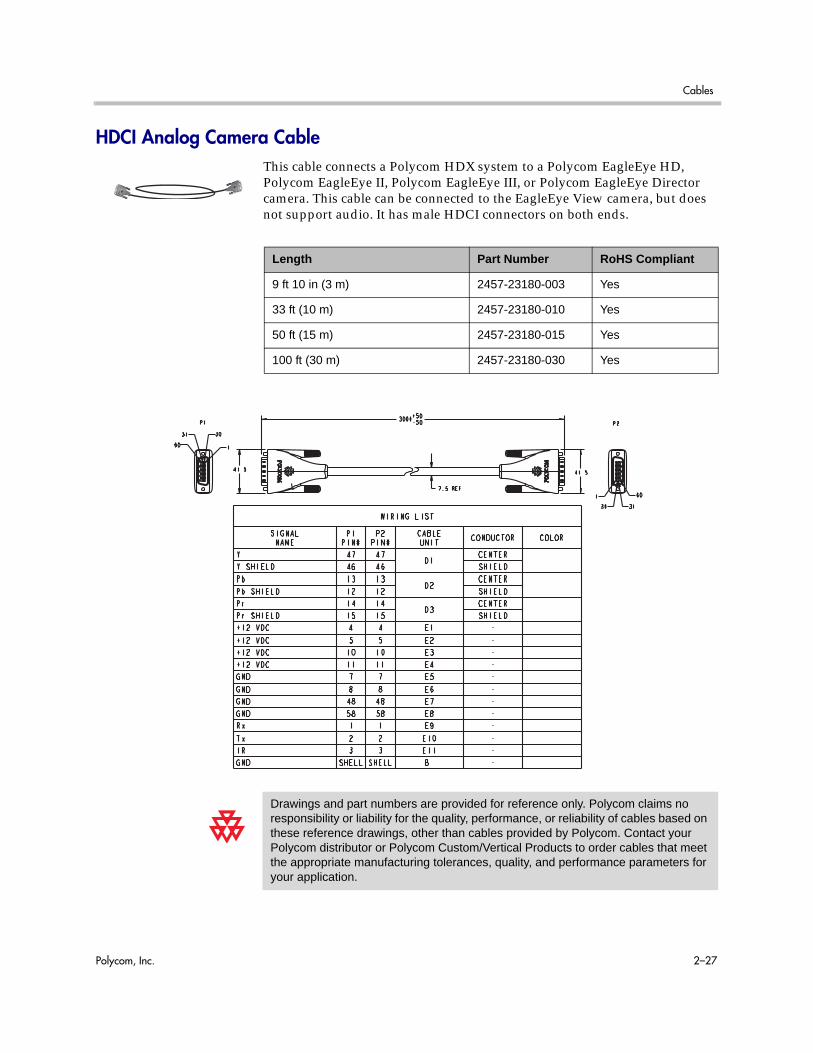
Cables
Polycom, Inc. 2–27
HDCI Analog Camera CableThis cable connects a Polycom HDX system to a Polycom EagleEye HD, Polycom EagleEye II, Polycom EagleEye III, or Polycom EagleEye Director camera. This cable can be connected to the EagleEye View camera, but does not support audio. It has male HDCI connectors on both ends.
Length Part Number RoHS Compliant
9 ft 10 in (3 m) 2457-23180-003 Yes
33 ft (10 m) 2457-23180-010 Yes
50 ft (15 m) 2457-23180-015 Yes
100 ft (30 m) 2457-23180-030 Yes
Drawings and part numbers are provided for reference only. Polycom claims no responsibility or liability for the quality, performance, or reliability of cables based on these reference drawings, other than cables provided by Polycom. Contact your Polycom distributor or Polycom Custom/Vertical Products to order cables that meet the appropriate manufacturing tolerances, quality, and performance parameters for your application.
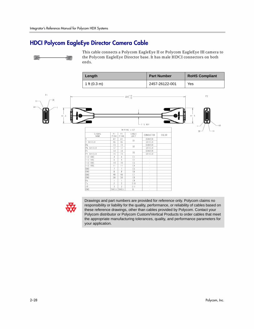
Integrator’s Reference Manual for Polycom HDX Systems
2–28 Polycom, Inc.
HDCI Polycom EagleEye Director Camera CableThis cable connects a Polycom EagleEye II or Polycom EagleEye III camera to the Polycom EagleEye Director base. It has male HDCI connectors on both ends.
Length Part Number RoHS Compliant
1 ft (0.3 m) 2457-26122-001 Yes
Drawings and part numbers are provided for reference only. Polycom claims no responsibility or liability for the quality, performance, or reliability of cables based on these reference drawings, other than cables provided by Polycom. Contact your Polycom distributor or Polycom Custom/Vertical Products to order cables that meet the appropriate manufacturing tolerances, quality, and performance parameters for your application.

Cables
Polycom, Inc. 2–29
As shown in the following figure, the EagleEye Director camera has seven microphones embedded in the base.
For information about positioning the camera, refer to the Administrator’s Guide for Polycom HDX Systems.
Vertical Mic Top
Vertical Mic Center
Horizontal Mic CenterHorizontal Mic Left Center Horizontal Mic Right Center
Horizontal Mic RightHorizontal Mic Left

Integrator’s Reference Manual for Polycom HDX Systems
2–30 Polycom, Inc.
HDCI Camera Break-Out CableThis cable breaks out the HDCI camera cable video and control signals to standard interfaces. This cable can be connected to the EagleEye View camera, but does not support audio.The five BNC connectors can be used to carry composite video, S-Video, or analog component YPbPr video. The DB-9 connector is used to connect to PTZ camera control interfaces. It is male HDCI to five female BNC and one female DB-9.
Length Part Number RoHS Compliant
1ft (0.3 m) 2457-23521-001 Yes
Drawings and part numbers are provided for reference only. Polycom claims no responsibility or liability for the quality, performance, or reliability of cables based on these reference drawings, other than cables provided by Polycom. Contact your Polycom distributor or Polycom Custom/Vertical Products to order cables that meet the appropriate manufacturing tolerances, quality, and performance parameters for your application.
Composite Svideo Component
Red C Pr
Green C Y Y
Blue Pb
Video Output
3 x
BNC
Universal Breakout Cable

Cables
Polycom, Inc. 2–31
VCR/DVD Composite CableThis cable connects a Polycom HDX system to a VCR or DVD player. It has triple RCA connectors on both ends. The Polycom HDX system requires a female RCA to male BNC adapter for the yellow video RCA connector, and the Audio Adapter Cable on page 2-54. The maximum approved length for this cable is 50 ft (15 m).
Length Part Number RoHS Compliant
8 ft (2.6 m) 2457-08412-001 —
Drawings and part numbers are provided for reference only. Polycom claims no responsibility or liability for the quality, performance, or reliability of cables based on these reference drawings, other than cables provided by Polycom. Contact your Polycom distributor or Polycom Custom/Vertical Products to order cables that meet the appropriate manufacturing tolerances, quality, and performance parameters for your application.

Integrator’s Reference Manual for Polycom HDX Systems
2–32 Polycom, Inc.
Composite Video CableThis cable connects a Polycom HDX system to a monitor or camera. It has single yellow RCA connectors on both ends. The Polycom HDX system requires a female RCA to male BNC adapter in order to connect to composite input or output. The maximum approved length for this cable is 100 ft (30 m).
Length Part Number RoHS Compliant
25 ft (7.6 m) 2457-09207-001 —
Drawings and part numbers are provided for reference only. Polycom claims no responsibility or liability for the quality, performance, or reliability of cables based on these reference drawings, other than cables provided by Polycom. Contact your Polycom distributor or Polycom Custom/Vertical Products to order cables that meet the appropriate manufacturing tolerances, quality, and performance parameters for your application.

Cables
Polycom, Inc. 2–33
PowerCam Plus Primary CableThis cable connects a Polycom HDX system to a Polycom PowerCam Plus camera using the HDCI PowerCam Plus Adapter Cable on page 2-35. It has 4-pin mini-DIN and DB-15 connectors on both ends.
Length Part Number RoHS Compliant
9 ft 10 in (3 m) 1457-50105-002 Yes
30 ft (9 m) 1457-50105-230 Yes
50 ft (15 m) 1457-50105-250 Yes
100 ft (30 m) 1457-50105-300 Yes
150 ft (45 m) 1457-50105-350 Yes
Drawings and part numbers are provided for reference only. Polycom claims no responsibility or liability for the quality, performance, or reliability of cables based on these reference drawings, other than cables provided by Polycom. Contact your Polycom distributor or Polycom Custom/Vertical Products to order cables that meet the appropriate manufacturing tolerances, quality, and performance parameters for your application.
1 5 7642 3 8
151412109 11 13
1
3 4
2
Front Viewof Connector
1
3 4
2
1 5 7642 3 8
151412109 11 13
P1 P2P3 P4
Front Viewof Connector
200mm / 7.87"200mm / 7.87"
3 Meters / 9' 10"
P1 Connector P2 Connector Pin # Signal Name Pin # Signal Name
1 Arm Mic 1 Arm Mic
2 Left Mic 2 Left Mic
3 A GND 3 A GND
4 Cam ID Bit 4 Cam ID Bit
5 P GND 5 P GND
6 +12V 6 +12V
7 SW-RX/SN-TX 7 SW-RX/SN-TX
8 IR signal 8 IR signal
9 Center Mic 9 Center Mic
10 Right Mic 10 Right Mic
11 A GND 11 A GND
12 P GND 12 P GND
13 +12V 13 +12V
14 SW-TX/SN-RX 14 SW-TX/SN-RX
15 IR return 15 IR return
P3 4 Pin mini Din P4 4 Pin mini Din 1 A GND 1 A GND
2 A GND 2 A GND
3 Luma 3 Luma
4 Chroma 4 Chroma
40mm / 1.57"
40mm / 1.57"
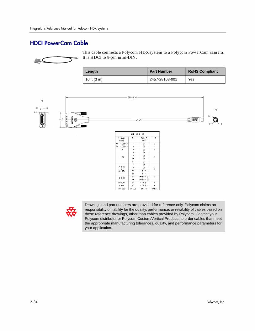
Integrator’s Reference Manual for Polycom HDX Systems
2–34 Polycom, Inc.
HDCI PowerCam CableThis cable connects a Polycom HDX system to a Polycom PowerCam camera. It is HDCI to 8-pin mini-DIN.
Length Part Number RoHS Compliant
10 ft (3 m) 2457-28168-001 Yes
Drawings and part numbers are provided for reference only. Polycom claims no responsibility or liability for the quality, performance, or reliability of cables based on these reference drawings, other than cables provided by Polycom. Contact your Polycom distributor or Polycom Custom/Vertical Products to order cables that meet the appropriate manufacturing tolerances, quality, and performance parameters for your application.

Cables
Polycom, Inc. 2–35
HDCI PowerCam Plus Adapter CableThis cable adapts a PowerCam Plus cable to HDCI. It is HDCI to 4-pin mini-DIN and DB-15. It can also be used with the PowerCam Primary Camera Cable on page 2-41 to connect PowerCam.
Length Part Number RoHS Compliant
1 ft (0.3 m) 2457-23481-001 Yes
Drawings and part numbers are provided for reference only. Polycom claims no responsibility or liability for the quality, performance, or reliability of cables based on these reference drawings, other than cables provided by Polycom. Contact your Polycom distributor or Polycom Custom/Vertical Products to order cables that meet the appropriate manufacturing tolerances, quality, and performance parameters for your application.

Integrator’s Reference Manual for Polycom HDX Systems
2–36 Polycom, Inc.
HDCI VISCA Adapter CableThis cable connects a Polycom HDX system HDCI video input to SD cameras with VISCA control that use a DB-9 serial connector. It is HDCI to 4-pin mini-DIN and DB-9. Standard S-Video and DB-9 serial cables are required to connect this cable to the camera.
Length Part Number RoHS Compliant
1 ft (0.3 m) 2457-23486-001 Yes
Drawings and part numbers are provided for reference only. Polycom claims no responsibility or liability for the quality, performance, or reliability of cables based on these reference drawings, other than cables provided by Polycom. Contact your Polycom distributor or Polycom Custom/Vertical Products to order cables that meet the appropriate manufacturing tolerances, quality, and performance parameters for your application.

Cables
Polycom, Inc. 2–37
HDCI Polycom EagleEye 1080 Camera CableThis cable connects a Polycom HDX system HDCI video input to a Polycom EagleEye 1080 camera or to a Sony HD camera. The cable is HDCI to 8-pin mini-DIN and HD-15.
Length Part Number RoHS Compliant
9 ft 10 in (3 m) 2457-28153-001 Yes
33 ft (10 m) 2457-28154-001 Yes
50 ft (15m) 2457-28154-050 Yes
100 ft (30m) 2457-28154-100 Yes
Drawings and part numbers are provided for reference only. Polycom claims no responsibility or liability for the quality, performance, or reliability of cables based on these reference drawings, other than cables provided by Polycom. Contact your Polycom distributor or Polycom Custom/Vertical Products to order cables that meet the appropriate manufacturing tolerances, quality, and performance parameters for your application.

Integrator’s Reference Manual for Polycom HDX Systems
2–38 Polycom, Inc.
HDCI Polycom EagleEye View Camera CableThis cable connects a Polycom HDX system HDCI video input to a Polycom EagleEye View camera. It has male HDCI connectors on both ends.
Length Part Number RoHS Compliant
9 ft 10 in (3 m) 2457-29759-001 Yes
33 ft (10 m) 2457-29759-010 Yes
Drawings and part numbers are provided for reference only. Polycom claims no responsibility or liability for the quality, performance, or reliability of cables based on these reference drawings, other than cables provided by Polycom. Contact your Polycom distributor or Polycom Custom/Vertical Products to order cables that meet the appropriate manufacturing tolerances, quality, and performance parameters for your application.

Cables
Polycom, Inc. 2–39
HDCI Sony VISCA Adapter CableThis cable connects a Polycom HDX system HDCI video input to a camera using Sony 8-pin mini-DIN VISCA and S-Video. It is HDCI to 8-pin mini-DIN and S-Video. Standard S-Video and Sony VISCA cables are required to connect this cable to the camera. The VISCA cable is a straight-through male 8-pin mini-DIN to male 8-pin mini-DIN serial cable.
Length Part Number RoHS Compliant
1 ft (0.3 m) 2457-23549-001 Yes
Drawings and part numbers are provided for reference only. Polycom claims no responsibility or liability for the quality, performance, or reliability of cables based on these reference drawings, other than cables provided by Polycom. Contact your Polycom distributor or Polycom Custom/Vertical Products to order cables that meet the appropriate manufacturing tolerances, quality, and performance parameters for your application.

Integrator’s Reference Manual for Polycom HDX Systems
2–40 Polycom, Inc.
HDCI EagleEye 1080 or Sony Adapter CableThis cable connects a Polycom system HDCI video input to the Polycom EagleEye 1080, Sony EVI-HD1 PTZ, or Sony BRC-H700 PTZ cameras. It is HDCI to 8-pin mini-DIN and HD-15. The maximum approved length for this cable is 100 ft (30 m).
Length Part Number RoHS Compliant
1 ft (0.3 m) 2457-23548-001 Yes
Drawings and part numbers are provided for reference only. Polycom claims no responsibility or liability for the quality, performance, or reliability of cables based on these reference drawings, other than cables provided by Polycom. Contact your Polycom distributor or Polycom Custom/Vertical Products to order cables that meet the appropriate manufacturing tolerances, quality, and performance parameters for your application.

Cables
Polycom, Inc. 2–41
PowerCam Primary Camera CableThis cable connects the Polycom HDX system video input 1 to a Polycom PowerCam camera up to 10 ft away when used with the HDCI PowerCam Plus Adapter Cable on page 2-35. It is 8-pin mini-DIN to 4-pin mini-DIN and DB-15. The maximum approved length for this cable is 10 ft (3 m).
Length Part Number RoHS Compliant
9 ft 10 in (3 m) 1457-50338-002 Yes
Drawings and part numbers are provided for reference only. Polycom claims no responsibility or liability for the quality, performance, or reliability of cables based on these reference drawings, other than cables provided by Polycom. Contact your Polycom distributor or Polycom Custom/Vertical Products to order cables that meet the appropriate manufacturing tolerances, quality, and performance parameters for your application.
P1 15 Pin D Connector P2 8 Pin mini Din Pin # Signal Name Wire Type Pin # Signal Name
1-4 N/C 5 PGND 22AWG wire 3 DGND 6 +12V 22 AWG wire 7 +12V 7 SW-RX/SN-TX 30 AWG wire 2 SW-RX/SN-TX 8 IR-SIGNAL 30 AWG wire 4 IR_SIGNAL
9-11 N/C 12 P GND 22 AWG wire 3 DGND 13 +12V 22 AWG wire 7 +12V 14 SW-TX/SN-RX 30 AWG wire 1 SW-TX/SN-RX 15 IR RETURN 30 AWG wire 3 DGND
SHIELD DRAIN wire SHIELD P3 4 Pin Mini Din
1 RTN Coax Shield 5 GVID 2 RTN Coax Shield 5 GVID 3 Luma Micro Coax 6 Luma 4 Chroma Micro Coax 8 Chroma
SHIELD DRAIN wire SHIELD
P1
3 Meters +/- 50.80mm4-40 Jack screw
Molded PVC strain reliefPan Int'l 73069-008-T06
8 Pin Mini DinMale
P2
15
76
42
38
1514
1210
911
13
P3
200mm / 7.87"
40mm(1.57")
1 342
15 Pin D-subMale
12
54
367
8
4Pin Mini DinMale

Integrator’s Reference Manual for Polycom HDX Systems
2–42 Polycom, Inc.
PowerCam Break-Out CableThis cable connects S-Video and control cables and a power supply to a Polycom PowerCam camera. This combination is required when using the PowerCam as the primary camera more than 10 ft away from the system, or as the secondary camera. It is 8-pin mini-DIN to 3-way breakout block.
A separate power supply is required (part number 1465-52621-036).
Length Part Number RoHS Compliant
6 ft (1.8 m) 2457-50526-200 Yes
6' ± 2. 0"
4 Pin Mini Di n Femal e
8 Pin Mini D i n Fe ma le
DC Ja ck
Molded PVC strain relief P2
1 2
5 4 3
6 7 8
1
3 4
2
J1 P1 J2 8 P i n M i n i Din
Ma le
CONNECTION TABLE CONNECTION TABLE Signal Name Signal Name
TXD TXD RXD RXD
DGND DGND IR-SIGNAL IR-SIGNAL CHROMAR CHROMAR
LUMAR LUMAR LUMA (Y) LUMA (Y)
+12V +12V CHROMA (C) CHROMA (C)
SHIELD SHIELD
P1 P1
1 1
2 2
P2 P2 1 1 2 2 3 3 4 4 5 5 5 5 6 6 7 7 8 8
Shield Shield
J1 J1
1 1 2 2 3 3
4 4
J2 J2 5 5 3 3
6 & 4 6 & 4 7 7
Shield Shield
Drawings and part numbers are provided for reference only. Polycom claims no responsibility or liability for the quality, performance, or reliability of cables based on these reference drawings, other than cables provided by Polycom. Contact your Polycom distributor or Polycom Custom/Vertical Products to order cables that meet the appropriate manufacturing tolerances, quality, and performance parameters for your application.

Cables
Polycom, Inc. 2–43
PowerCam Plus/VISCA Control Cable
8-pin mini-DIN to DB-15This cable adapts the 8-pin mini-DIN VISCA control interface to the PowerCam Plus DB-15 control interface. It is used with the PowerCam Break-Out cable and the HDCI PowerCam Plus adapter cable. It is 8-pin mini-DIN to DB-15.
Length Part Number RoHS Compliant
50 ft (15 m) 1457-50527-201 Yes
Drawings and part numbers are provided for reference only. Polycom claims no responsibility or liability for the quality, performance, or reliability of cables based on these reference drawings, other than cables provided by Polycom. Contact your Polycom distributor or Polycom Custom/Vertical Products to order cables that meet the appropriate manufacturing tolerances, quality, and performance parameters for your application.
P1 15 Pin D Connector P2 VISCA 8 Pin mini Din Pin # Signal Name Pin # Signal Name 1-6, 9-11, 13 NC 1, 2, 8 NC
7 SW-RX/SN-TX 3 SW-RX/SN-TX 8 IR-SIGNAL 7 IR OUT
12 P GND 4 GND 14 SW-TX/SN-RX 5 SW-TX/SN-RX 15 IR RETURN 6 GND
SHIELD SHIELD
15 Pin D-subMale
P1
50' ± 3.0"
P215
76
42
38
15
14
12
10
91
11
3
8 Pin Mini DinMale
12
54
367
8
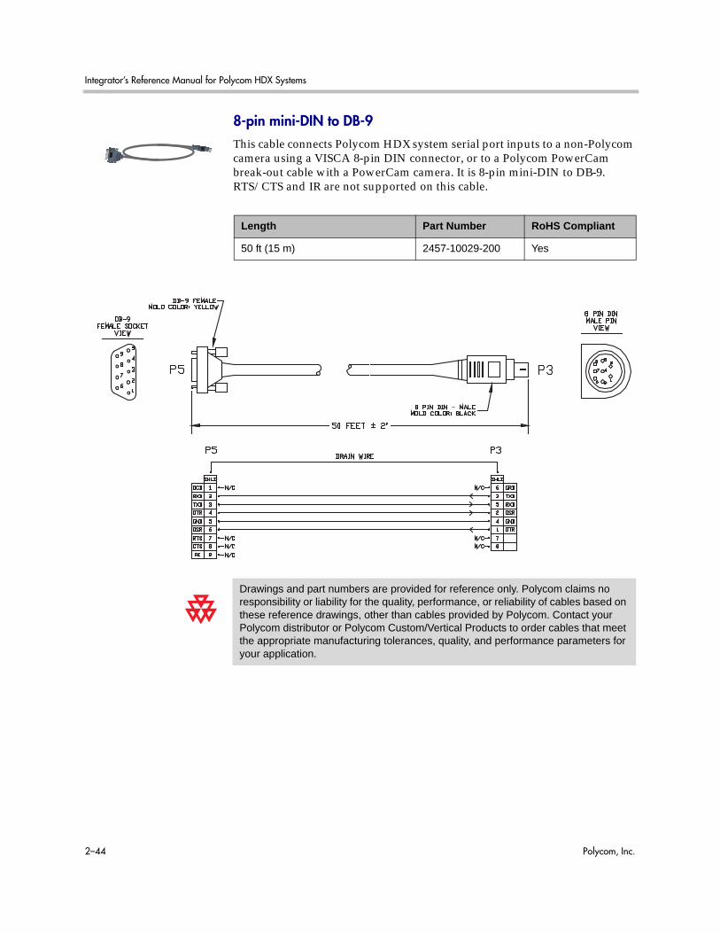
Integrator’s Reference Manual for Polycom HDX Systems
2–44 Polycom, Inc.
8-pin mini-DIN to DB-9This cable connects Polycom HDX system serial port inputs to a non-Polycom camera using a VISCA 8-pin DIN connector, or to a Polycom PowerCam break-out cable with a PowerCam camera. It is 8-pin mini-DIN to DB-9. RTS/CTS and IR are not supported on this cable.
Length Part Number RoHS Compliant
50 ft (15 m) 2457-10029-200 Yes
Drawings and part numbers are provided for reference only. Polycom claims no responsibility or liability for the quality, performance, or reliability of cables based on these reference drawings, other than cables provided by Polycom. Contact your Polycom distributor or Polycom Custom/Vertical Products to order cables that meet the appropriate manufacturing tolerances, quality, and performance parameters for your application.

Cables
Polycom, Inc. 2–45
People+Content CableThis cable connects a PC with VGA and 3.5mm stereo audio output to the DVI and 3.5 mm audio input of the HDX system.
Length Part Number RoHS Compliant
25 ft (7.62 m) 2457-28665-001 Yes
Drawings and part numbers are provided for reference only. Polycom claims no responsibility or liability for the quality, performance, or reliability of cables based on these reference drawings, other than cables provided by Polycom. Contact your Polycom distributor or Polycom Custom/Vertical Products to order cables that meet the appropriate manufacturing tolerances, quality, and performance parameters for your application.

Integrator’s Reference Manual for Polycom HDX Systems
2–46 Polycom, Inc.
Audio Cables
Polycom HDX Microphone Host CableFor more information about supported microphone configurations, refer to the Administrator’s Guide for Polycom HDX Systems.
This cable connects a Polycom HDX system to the Polycom SoundStructure C-Series mixer. It is unkeyed male RJ-45 on both ends.
Length Part Number RoHS Compliant
18 in (0.5 m) 2457-23574-001 Yes
25 ft (7.5 m) 2457-23217-001 Yes
876521
P1
3SHELL
872165
P2
3SHELL
BROWNWHITE/BROWNORANGEWHITE/ORANGEGREENWHITE/GREENCOLOR
DRAIN WIRESHIELD
P1 - RJ-45 shielded plug, Tyco 5-569552 or equivalentP2 - RJ-45 shielded plug, Tyco 5-569552 or equivalent
242424242424
AWG
Cables
Polycom, Inc. 2–47
When connecting two Polycom HDX microphone host devices, a cross-over cable is required. To build a custom cross-over cable for this purpose, you should use shielded CAT5 or better cable. Each end of the custom cable should have a shielded RJ-45 plug connector that connects to a Polycom HDX microphone host device. The maximum supported cable length is 100 feet.
Due to differing use of the twisted pairs within the cable, the pinout for this custom CAT5 cross-over cable is not the same as the pinout that is used for standard Ethernet cables. Do not use standard Ethernet cables. Instead, for best cable performance, refer to the following pinout information to create this custom CAT5 cross-over cable.
Drawings and part numbers are provided for reference only. Polycom claims no responsibility or liability for the quality, performance, or reliability of cables based on these reference drawings, other than cables provided by Polycom. Contact your Polycom distributor or Polycom Custom/Vertical Products to order cables that meet the appropriate manufacturing tolerances, quality, and performance parameters for your application.

Integrator’s Reference Manual for Polycom HDX Systems
2–48 Polycom, Inc.
Polycom HDX Microphone Array CableFor more information about supported microphone configurations, refer to the Administrator’s Guide for Polycom HDX Systems.
This cable connects two Polycom HDX microphones together. This cable can also be used with the Polycom HDX Microphone Array Cable Adapter on page 2-49 to connect a Polycom HDX system to a Polycom HDX microphone array or to a SoundStation IP 7000 phone. It has male Walta connectors on both ends.
Length Part Number RoHS Compliant
15 ft (4.6 m) 2457-23215-001 Yes
25 ft (7.6 m) 2457-23216-001 Yes
Drawings and part numbers are provided for reference only. Polycom claims no responsibility or liability for the quality, performance, or reliability of cables based on these reference drawings, other than cables provided by Polycom. Contact your Polycom distributor or Polycom Custom/Vertical Products to order cables that meet the appropriate manufacturing tolerances, quality, and performance parameters for your application.
BROWN HEAT-SHRINK TUBINGBROWN HEAT-SHRINK TUBINGP1P1 P2P2

Cables
Polycom, Inc. 2–49
Polycom HDX Microphone Array Cable AdapterFor more information about supported microphone cable configurations, refer to the Administrator’s Guide for Polycom HDX Systems.
This cable adapts the Polycom HDX Microphone Array Cable on page 2-48 for use with the Polycom HDX 9000 Series system and the SoundStructure C-Series mixer. It is male RJ-45 to female Walta.
The following diagram shows microphone connection options for Polycom HDX 9000 Series systems, using cables available from Polycom.
.
Length Part Number RoHS Compliant
18 in (0.5 m) 2457-23716-001 Yes
Do not connect Polycom microphone cables or devices to the Ethernet port, and do not connect an Ethernet cable or device to the Polycom microphone input.
Drawings and part numbers are provided for reference only. Polycom claims no responsibility or liability for the quality, performance, or reliability of cables based on these reference drawings, other than cables provided by Polycom. Contact your Polycom distributor or Polycom Custom/Vertical Products to order cables that meet the appropriate manufacturing tolerances, quality, and performance parameters for your application.
Polycom HDX Microphone Cable Adapter Polycom HDX Microphone Cables

Integrator’s Reference Manual for Polycom HDX Systems
2–50 Polycom, Inc.
Polycom HDX Ceiling Microphone Adaptor CableThis cable connects a Polycom HDX system to the Polycom microphone array. It is male Walta to RJ-45.
Length Part Number RoHS Compliant
25 ft (7.6 m) 2457-25646-001 Yes
Drawings and part numbers are provided for reference only. Polycom claims no responsibility or liability for the quality, performance, or reliability of cables based on these reference drawings, other than cables provided by Polycom. Contact your Polycom distributor or Polycom Custom/Vertical Products to order cables that meet the appropriate manufacturing tolerances, quality, and performance parameters for your application.
18.00 IN +/-.125"
DETAIL "A"
KEY

Cables
Polycom, Inc. 2–51
Custom Cabling for Polycom HDX MicrophonesYou can create a custom-length cable that connects a Polycom HDX system to a Polycom HDX microphone. Start with the microphone cable (part number 2457-23216-001), and cut off the P1 end. Using the wiring tables shown, create a custom cable from the microphone to a wall plate or other interfacing device. Next, from the wall plate or other interfacing device, run shielded CAT5 or better cable to the Polycom HDX system, terminating with a shielded RJ-45 plug connector.
The total length from the Polycom HDX system to the first Polycom microphone can vary between 18 in and 100 ft. The maximum length between subsequent microphones is 25 ft.
The following diagram shows an example of longer custom cabling from a Polycom HDX system to a Polycom microphone or a Polycom SoundStation IP 7000 Phone.
.
The following steps explain how to wire this custom cable configuration.
1 Identify the P1 connector on the Polycom HDX microphone cable according to the location of the brown heat-shrink tubing as shown on page 2-48. Remove the P1 connector and skip to step 4. Note that two separate vendors manufacture these cables, which are electrically equivalent but have different color coding. If you cannot identify the P1 connector, remove either connector from the cable and continue with step 2.
The following tables show the color coding for the cable wiring.
Polycom HDXCut and Re-terminatedPolycom HDX Microphone Cable
Interfacing Device such as a Wall PlateCAT5 Shielded Cable
Microphone Cable
P1101426
1393
SHELL
P226
10141393
SHELL
AWG282828282424
COLORREDORANGEYELLOWGREENWHITEBLACKDRAIN WIRESHIELD
VENDOR 1
P1, P2 - Walta Electronics, M30-558-0051
P1101426
1393
SHELL
P22610141393
SHELL
AWG282828282424
COLORBLUEYELLOWORANGEGREENBLACKWHITEDRAIN WIRESHIELD
VENDOR 2
P1, P2 - Walta Electronics, M30-558-0051
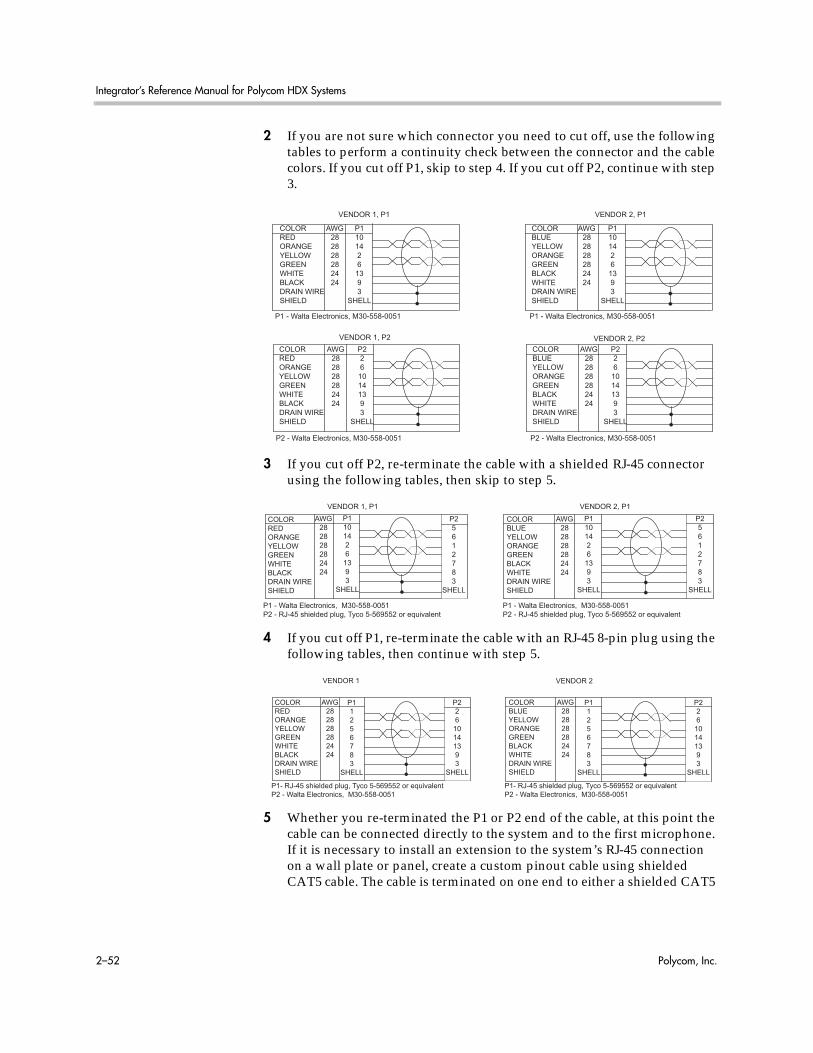
Integrator’s Reference Manual for Polycom HDX Systems
2–52 Polycom, Inc.
2 If you are not sure which connector you need to cut off, use the following tables to perform a continuity check between the connector and the cable colors. If you cut off P1, skip to step 4. If you cut off P2, continue with step 3.
3 If you cut off P2, re-terminate the cable with a shielded RJ-45 connector using the following tables, then skip to step 5.
4 If you cut off P1, re-terminate the cable with an RJ-45 8-pin plug using the following tables, then continue with step 5.
5 Whether you re-terminated the P1 or P2 end of the cable, at this point the cable can be connected directly to the system and to the first microphone. If it is necessary to install an extension to the system’s RJ-45 connection on a wall plate or panel, create a custom pinout cable using shielded CAT5 cable. The cable is terminated on one end to either a shielded CAT5
P1101426
1393
SHELL
AWG282828282424
COLORREDORANGEYELLOWGREENWHITEBLACKDRAIN WIRESHIELD
VENDOR 1, P1
P1101426
1393
SHELL
AWG282828282424
COLORBLUEYELLOWORANGEGREENBLACKWHITEDRAIN WIRESHIELD
VENDOR 2, P1
P1 - Walta Electronics, M30-558-0051 P1 - Walta Electronics, M30-558-0051
P226
10141393
SHELL
AWG282828282424
COLORREDORANGEYELLOWGREENWHITEBLACKDRAIN WIRESHIELD
VENDOR 1, P2P226
10141393
SHELL
AWG282828282424
COLORBLUEYELLOWORANGEGREENBLACKWHITEDRAIN WIRESHIELD
VENDOR 2, P2
P2 - Walta Electronics, M30-558-0051 P2 - Walta Electronics, M30-558-0051
P1 - Walta Electronics, M30-558-0051P2 - RJ-45 shielded plug, Tyco 5-569552 or equivalent
P1101426
1393
SHELL
P25612783
SHELL
AWG282828282424
COLORREDORANGEYELLOWGREENWHITEBLACKDRAIN WIRESHIELD
P1101426
1393
SHELL
P25612783
SHELL
AWG282828282424
COLORBLUEYELLOWORANGEGREENBLACKWHITEDRAIN WIRESHIELD
VENDOR 1, P1 VENDOR 2, P1
P1 - Walta Electronics, M30-558-0051P2 - RJ-45 shielded plug, Tyco 5-569552 or equivalent
P1- RJ-45 shielded plug, Tyco 5-569552 or equivalentP2 - Walta Electronics, M30-558-0051
P1- RJ-45 shielded plug, Tyco 5-569552 or equivalentP2 - Walta Electronics, M30-558-0051
P11256783
SHELL
P226
10141393
SHELL
AWG282828282424
COLORREDORANGEYELLOWGREENWHITEBLACKDRAIN WIRESHIELD
P11256783
SHELL
P226
10141393
SHELL
AWG282828282424
COLORBLUEYELLOWORANGEGREENBLACKWHITEDRAIN WIRESHIELD
VENDOR 1 VENDOR 2

Cables
Polycom, Inc. 2–53
keystone jack or, if using a shielded panel coupler, a shielded RJ-45 plug connector. The other end terminates to a shielded RJ-45 plug that connects to the Polycom HDX system.
The Polycom RJ-45 connector pinout is custom. For best performance, follow the wiring tables shown in this document. If standard Ethernet cables are used, signal integrity cannot be guaranteed and degraded performance may occur, especially at longer lengths.
P1 - RJ-45 shielded Keystone jack, L-com RJ110C5-S or equivalent ORP1 - RJ-45 shielded plug, Tyco 5-569552 or equivalent with shielded RJ-45 panel coupler kit (L-com ECF504-SC5E or equivalent)P2- RJ-45 shielded plug, Tyco 5-569552 or equivalent
P11256783
SHELL
AWG242424242424
COLORWHITE/GREENGREENWHITE/ORANGEORANGEWHITE/BROWNBROWNDRAIN WIRESHIELD
P21256783
SHELL

Integrator’s Reference Manual for Polycom HDX Systems
2–54 Polycom, Inc.
Audio Adapter CableThis cable adapts the Polycom HDX system Phoenix audio connectors to standard RCA audio cables, such as the Audio Cable on page 2-55. It is dual male Phoenix to dual female RCA connectors (red/white).
Length Part Number RoHS Compliant
1 ft (0.3 m) 2457-23492-001 Yes
Drawings and part numbers are provided for reference only. Polycom claims no responsibility or liability for the quality, performance, or reliability of cables based on these reference drawings, other than cables provided by Polycom. Contact your Polycom distributor or Polycom Custom/Vertical Products to order cables that meet the appropriate manufacturing tolerances, quality, and performance parameters for your application.
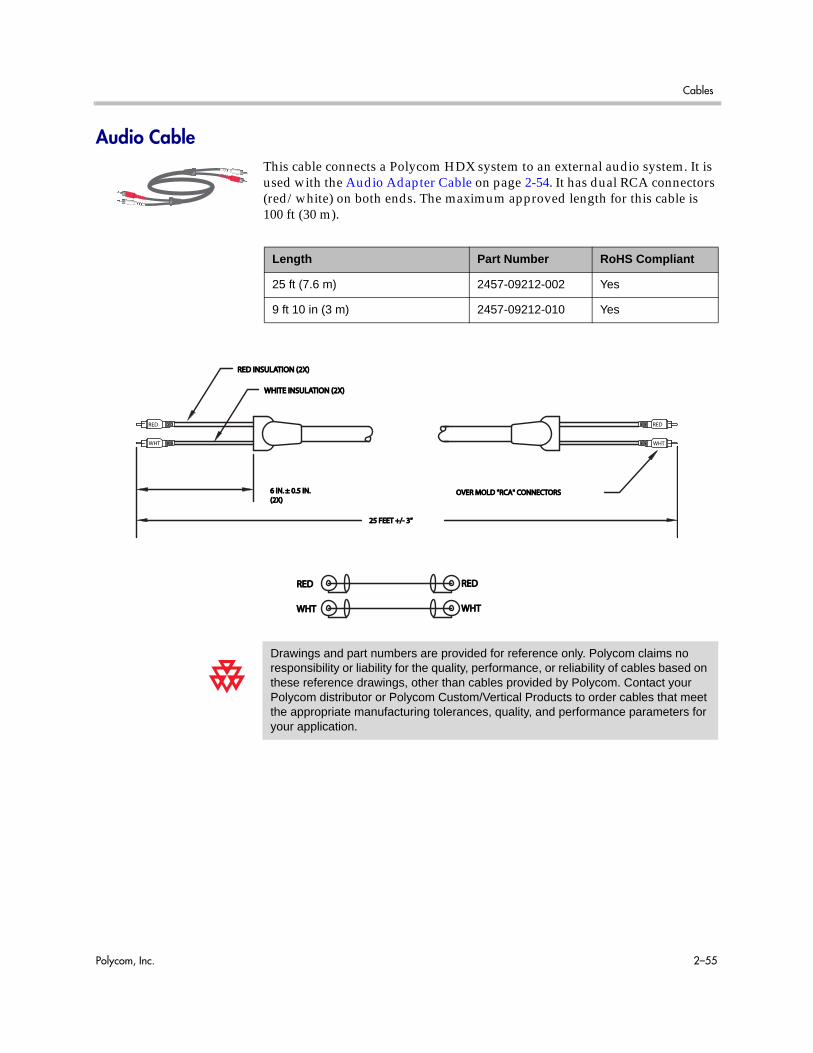
Cables
Polycom, Inc. 2–55
Audio CableThis cable connects a Polycom HDX system to an external audio system. It is used with the Audio Adapter Cable on page 2-54. It has dual RCA connectors (red/white) on both ends. The maximum approved length for this cable is 100 ft (30 m).
Length Part Number RoHS Compliant
25 ft (7.6 m) 2457-09212-002 Yes
9 ft 10 in (3 m) 2457-09212-010 Yes
Drawings and part numbers are provided for reference only. Polycom claims no responsibility or liability for the quality, performance, or reliability of cables based on these reference drawings, other than cables provided by Polycom. Contact your Polycom distributor or Polycom Custom/Vertical Products to order cables that meet the appropriate manufacturing tolerances, quality, and performance parameters for your application.
OVER MOLD "RCA" CONNECTORSOVER MOLD "RCA" CONNECTORS
REDRED
WHTWHT WHTWHT
REDRED
25 FEET +/- 3"25 FEET +/- 3"
WHITE INSULATION (2X)WHITE INSULATION (2X)
RED INSULATION (2X)RED INSULATION (2X)
6 IN. ± 0.5 IN.6 IN. ± 0.5 IN.(2X)(2X)
RED RED
WHT WHT
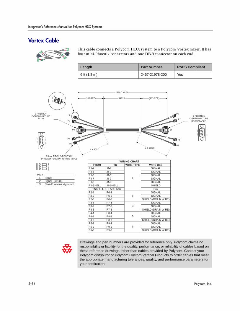
Integrator’s Reference Manual for Polycom HDX Systems
2–56 Polycom, Inc.
Vortex CableThis cable connects a Polycom HDX system to a Polycom Vortex mixer. It has four mini-Phoenix connectors and one DB-9 connector on each end.
Length Part Number RoHS Compliant
6 ft (1.8 m) 2457-21978-200 Yes
Drawings and part numbers are provided for reference only. Polycom claims no responsibility or liability for the quality, performance, or reliability of cables based on these reference drawings, other than cables provided by Polycom. Contact your Polycom distributor or Polycom Custom/Vertical Products to order cables that meet the appropriate manufacturing tolerances, quality, and performance parameters for your application.
56.0
WRAP LABEL
3.5mm PITCH 3-POSITIONPHOENIX PLUG PN 1840379 (8 PL)
P2
1
23
P3
J1
9-POSITIOND-SUBMINIATURE
PLUG
P4
P5
1422.0(203 REF) (203 REF)
4 X 305.04 X 203.0
P6
P7
P8
P9
FROM TO WIRE TYPE WIRE USEP1-2 J1-2 SIGNAL
P1-3 J1-3 SIGNAL
P1-5 J1-5 SIGNAL
P1-7 J1-7 SIGNAL
P1-8 J1-8 SIGNAL
P1-SHELL J1-SHELL SHIELD
N/A
P2-1 P6-1 SIGNAL
P2-2 P6-2 SIGNAL
P2-3 P6-3 SHIELD (DRAIN WIRE)
P3-1 P7-1 SIGNAL
P3-2 P7-2 SIGNAL
P3-3 P7-3 SHIELD (DRAIN WIRE)
P4-1 P8-1 SIGNAL
P4-2 P8-2 SIGNAL
P4-3 P8-3 SHIELD (DRAIN WIRE)
P5-1 P9-1 SIGNAL
P5-2 P9-2 SIGNAL
P5-3 P9-3 SHIELD (DRAIN WIRE)
WIRING CHART
B
A
PINS 1, 4, 6, 9 ARE N/C
B
B
B
P1
9-POSITIOND-SUBMINIATURE
RECEPTACLE
1829.0 +/- 50
1
234
5
67
89
5
43
21
98
76
Signal +Signal - (return) Shield/darin wire/ground
123
PIN #
123

Cables
Polycom, Inc. 2–57
3.5mm Screw Cage ConnectorThis 3-pin connector connects audio input and output to the Polycom HDX system. It also connects the IR sensor input on a Polycom HDX system to an external IR receiver, such as Xantech models 780-80, 780-90, 480-00, and 490-90.
The following table shows how to wire this connector for 2-wire connections, Phoenix to RCA.
Length Part Number RoHS Compliant
— 1515-41597-001 Yes
Drawings and part numbers are provided for reference only. Polycom claims no responsibility or liability for the quality, performance, or reliability of cables based on these reference drawings, other than cables provided by Polycom. Contact your Polycom distributor or Polycom Custom/Vertical Products to order cables that meet the appropriate manufacturing tolerances, quality, and performance parameters for your application.
Signal +Signal +Signal - (return) Signal - (return) Shield/drain wire/groundShield/drain wire/ground
123
PIN #PIN #
123
+12 V+12 VGround Ground IR signalIR signal
123
PIN #PIN #
Pinout for audio connectorPinout for audio connector Pinout for IR connectorPinout for IR connector
Top ViewTop View
Phoenix Contact RCA Contact
1 Center
2 Shell
3 —
Install jumper between contact 2 and contact 3 on the Phoenix connector.

Integrator’s Reference Manual for Polycom HDX Systems
2–58 Polycom, Inc.
Subwoofer Volume AttenuatorThis attenuator plugs into the Volume Control RJ-11 port on the subwoofer that comes with the Polycom stereo speaker kit. The attenuator is required for proper operation of the acoustic echo cancellation. It has an RJ-11 connector.
Length Part Number RoHS Compliant
3.5 in (9 cm) 1457-52415-001 —
Drawings and part numbers are provided for reference only. Polycom claims no responsibility or liability for the quality, performance, or reliability of cables based on these reference drawings, other than cables provided by Polycom. Contact your Polycom distributor or Polycom Custom/Vertical Products to order cables that meet the appropriate manufacturing tolerances, quality, and performance parameters for your application.

Cables
Polycom, Inc. 2–59
Polycom EagleEye Director Audio Feedback Phoenix to Phoenix Cable
This cable connects a Polycom HDX 9000 series system or Polycom SoundStructure C-Series Mixer to the Polycom EagleEye Director camera and the room audio playback system. It is dual male Phoenix connectors (for HDX systems or SoundStructure C-Series Mixer) to dual male Phoenix connectors (for the EagleEye Director camera) with dual female Phoenix connectors (for the room audio playback system).
Length Part Number RoHS Compliant
9.10 ft (3 m) 2457-82586-001 Yes
Drawings and part numbers are provided for reference only. Polycom claims no responsibility or liability for the quality, performance, or reliability of cables based on these reference drawings, other than cables provided by Polycom. Contact your Polycom distributor or Polycom Custom/Vertical Products to order cables that meet the appropriate manufacturing tolerances, quality, and performance parameters for your application.
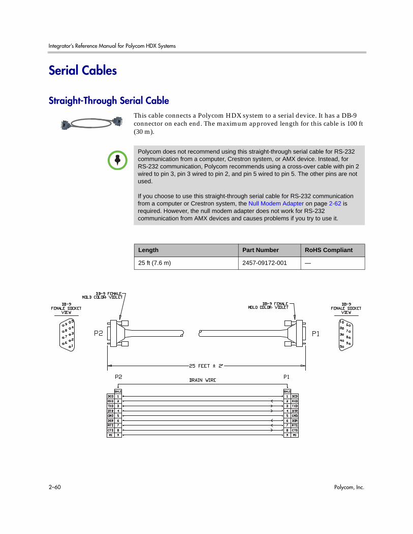
Integrator’s Reference Manual for Polycom HDX Systems
2–60 Polycom, Inc.
Serial Cables
Straight-Through Serial CableThis cable connects a Polycom HDX system to a serial device. It has a DB-9 connector on each end. The maximum approved length for this cable is 100 ft (30 m).
Polycom does not recommend using this straight-through serial cable for RS-232 communication from a computer, Crestron system, or AMX device. Instead, for RS-232 communication, Polycom recommends using a cross-over cable with pin 2 wired to pin 3, pin 3 wired to pin 2, and pin 5 wired to pin 5. The other pins are not used.
If you choose to use this straight-through serial cable for RS-232 communication from a computer or Crestron system, the Null Modem Adapter on page 2-62 is required. However, the null modem adapter does not work for RS-232 communication from AMX devices and causes problems if you try to use it.
Length Part Number RoHS Compliant
25 ft (7.6 m) 2457-09172-001 —

Cables
Polycom, Inc. 2–61
The DB-9 male connector on the Polycom HDX system has the following connections.
Most devices that connect to the serial port to control the Polycom HDX system through the API only require pins 2, 3, and 5. For more information and to verify the proper cabling, refer to the documentation for your control system.
Drawings and part numbers are provided for reference only. Polycom claims no responsibility or liability for the quality, performance, or reliability of cables based on these reference drawings, other than cables provided by Polycom. Contact your Polycom distributor or Polycom Custom/Vertical Products to order cables that meet the appropriate manufacturing tolerances, quality, and performance parameters for your application.
Pin Signal
1 Not used
2 Rx
3 Tx
4 DTR (tied to pin 6, DSR)
5 GND
6 DSR (tied to pin 4, DTR)
7 RTS
8 CTS
9 Not used
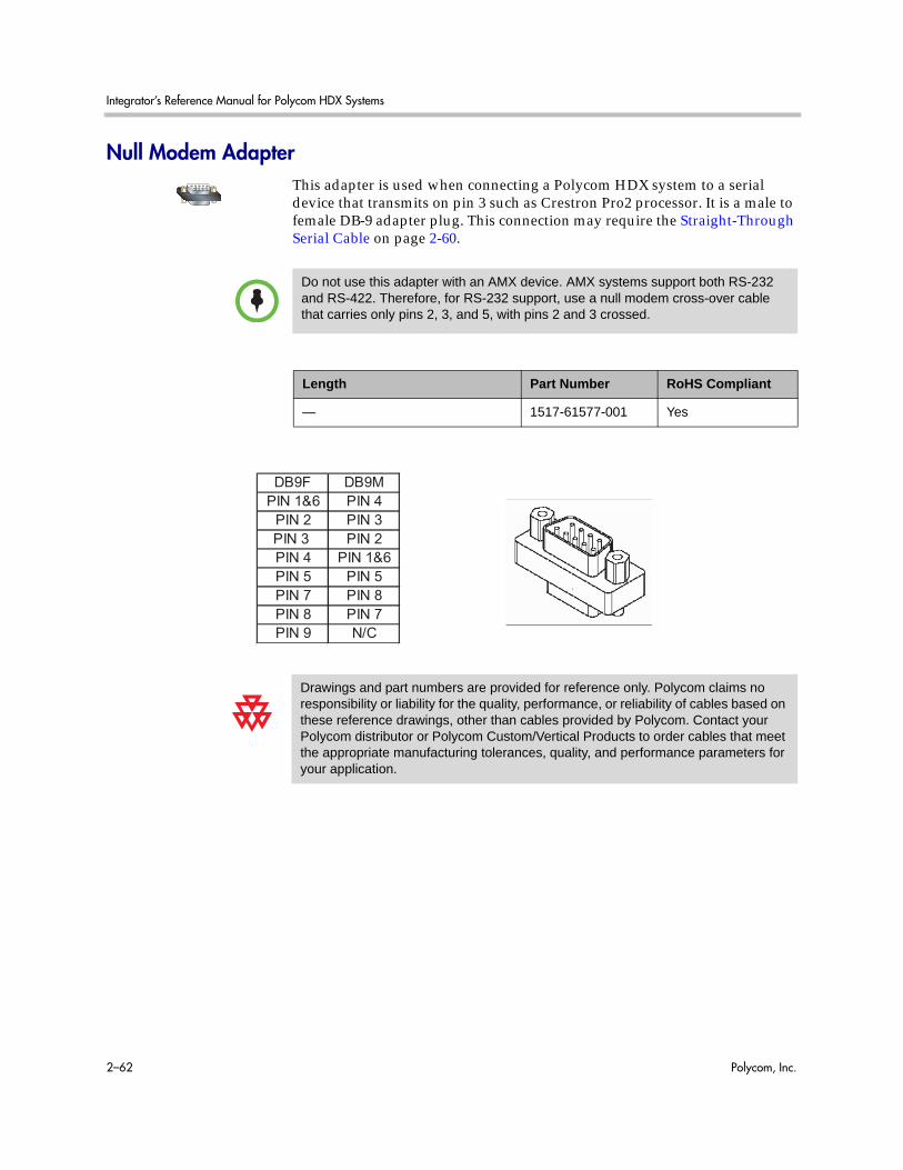
Integrator’s Reference Manual for Polycom HDX Systems
2–62 Polycom, Inc.
Null Modem AdapterThis adapter is used when connecting a Polycom HDX system to a serial device that transmits on pin 3 such as Crestron Pro2 processor. It is a male to female DB-9 adapter plug. This connection may require the Straight-Through Serial Cable on page 2-60.
Do not use this adapter with an AMX device. AMX systems support both RS-232 and RS-422. Therefore, for RS-232 support, use a null modem cross-over cable that carries only pins 2, 3, and 5, with pins 2 and 3 crossed.
Length Part Number RoHS Compliant
— 1517-61577-001 Yes
Drawings and part numbers are provided for reference only. Polycom claims no responsibility or liability for the quality, performance, or reliability of cables based on these reference drawings, other than cables provided by Polycom. Contact your Polycom distributor or Polycom Custom/Vertical Products to order cables that meet the appropriate manufacturing tolerances, quality, and performance parameters for your application.
DB9F DB9M
PIN 1&6 PIN 4
PIN 2 PIN 3
PIN 3 PIN 2
PIN 4 PIN 1&6
PIN 5 PIN 5
PIN 7 PIN 8
PIN 8 PIN 7
PIN 9 N/C

Polycom, Inc. 3–1
3Using the API
The Application Programming Interface (API) is a set of commands for advanced users who want to automate a Polycom HDX system. You can use the API by connecting a control system or computer RS-232 serial port to a Polycom HDX 9000, Polycom HDX 8000, or Polycom HDX 7000 series system. You can also use Telnet over the LAN to use the API with Polycom HDX 9000, Polycom HDX 8000, Polycom HDX 7000, and Polycom HDX 6000 series systems.
Using the API with an RS-232 InterfaceIf you use an RS-232 interface to send API commands, you must connect and configure the control system or computer and the Polycom HDX system for serial communication.
Configuring the RS-232 InterfaceIf you use the API with a serial connection, make sure that the RS-232 interfaces of the Polycom HDX system and your computer are configured appropriately.
To access the RS-232 settings on your system, do one of the following:
— In the local interface, go to System > Admin Settings > General Settings > Serial Port.
— In the web interface, go to Admin Settings > General Settings > Serial Port.

Integrator’s Reference Manual for Polycom HDX Systems
3–2 Polycom, Inc.
Configure the Baud Rate and RS-232 Mode options as follows:
The RS-232 port on the Polycom HDX system supports the following modes:
• Camera PTZ
• Closed Caption
• Control
• Pass-Thru
• Vortex Mixer
In Control Mode, a device (for example, a computer) connected to the RS-232 port can control the system using the API.
In Pass-Thru Mode, the operational modes of both devices’ RS-232 ports depend on the port configuration of each device.
OptionConfigure this way on your computer
Configure this way on the Polycom HDX system
Baud Rate Must be the same rate for both devices. Available rates are:
• 9600
• 14400
• 19200
• 38400
• 57600
• 115200
RS-232 Mode — Control
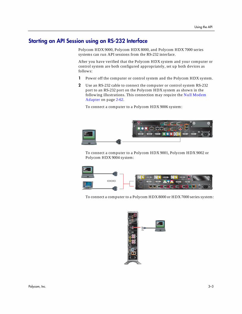
Using the API
Polycom, Inc. 3–3
Starting an API Session using an RS-232 InterfacePolycom HDX 9000, Polycom HDX 8000, and Polycom HDX 7000 series systems can run API sessions from the RS-232 interface.
After you have verified that the Polycom HDX system and your computer or control system are both configured appropriately, set up both devices as follows:
1 Power off the computer or control system and the Polycom HDX system.
2 Use an RS-232 cable to connect the computer or control system RS-232 port to an RS-232 port on the Polycom HDX system as shown in the following illustrations. This connection may require the Null Modem Adapter on page 2-62.
To connect a computer to a Polycom HDX 9006 system:
To connect a computer to a Polycom HDX 9001, Polycom HDX 9002 or Polycom HDX 9004 system:
To connect a computer to a Polycom HDX 8000 or HDX 7000 series system:
IOIOIO
44V
CR/D
VD
3
VC
R/DV
D
3A
UX
Integrator’s Reference Manual for Polycom HDX Systems
3–4 Polycom, Inc.
3 Power on the computer or control system and the Polycom HDX system.
4 From the computer or control system, start a serial session using HyperTerminal or another appropriate utility.
Using the API with the Maximum Security Profile EnabledYou must log in with a password to start an RS-232 session if the system is configured with the Security Profile set to Maximum.
You can log in with either the Admin ID and Admin Remote Password or the User ID and User Remote Password of the Polycom HDX system. The availability of individual API commands depends on whether you log in using a User or Admin ID. For a complete list of API commands and parameters available to the user and admin IDs, refer to Secure RS-232 Interface API Permissions on page D-1 .
For more information about the Security Profile, refer to the Security Deployment Guide for Polycom HDX Systems.
Using the API with a LAN ConnectionIf you have a computer connected to the LAN, you can send API commands to the Polycom HDX system through Telnet port 24.
1 On the computer, open a command line interface.
2 Start a Telnet session using the Polycom HDX system IP address and port number — for example, telnet 10.11.12.13 24.
You cannot use Telnet to access the system if Security Mode is enabled.
Using the API Controller CodeIn cooperation with the leading touch panel controller manufacturers, Polycom Video Division is proud to offer its own version of controller code designed to run on Crestron and AMX systems. This independent code base was developed specifically to address issues of code compatibility with video system software releases. It provides a fully executable controller program but also serves as a guideline for ongoing development using Polycom preferred methodology and commands.
To download the API controller code, refer to www.polycom.com/forms/amx_code.html. Additionally, AMX controller code or Crestron controller code is available for controlling the Polycom EagleEye HD camera. Companion documents are also available to further explain how to interface your controller with Polycom video systems and use the API efficiently.

Using the API
Polycom, Inc. 3–5
Additional API ResourcesThe following online resources are available for your reference as you use the API.
Technical Support Contact InformationTo contact Polycom Technical Support, go to www.polycom.com/support. This web site provides you with contact information for Polycom technical support. Use this web site when you need help using the API.
Feature Enhancement Request Web SiteGo to www.polycom.com/support, and navigate to Feature Request. This web site allows you to submit suggestions for feature enhancements. Use this web site when you have requests for future development of the Polycom API.
Video Test NumbersRefer to www.polycom.com/videotest. This web site provides you with test numbers of various Polycom systems worldwide. Use this web site when you need to access video test numbers to use when testing your Polycom system.
Knowledge BaseRefer to the Knowledge Base at www.polycom.com/support. This tool allows you to search for user guides, release notes, and other forms of product documentation. You can also search for troubleshooting information and technical briefs. Use this web site when you need to access Polycom product documentation or tips.

Integrator’s Reference Manual for Polycom HDX Systems
3–6 Polycom, Inc.

Polycom, Inc. 4–1
4System Commands
This chapter describes the API commands for software version 3.0.3.
For an alphabetical list of all the commands, refer to the table of contents for this document. For a list of commands by category, refer to the Categorical List of API Commands command on page E-1.
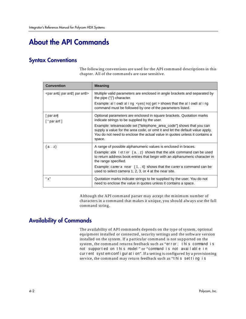
Integrator’s Reference Manual for Polycom HDX Systems
4–2 Polycom, Inc.
About the API Commands
Syntax ConventionsThe following conventions are used for the API command descriptions in this chapter. All of the commands are case sensitive.
Although the API command parser may accept the minimum number of characters in a command that makes it unique, you should always use the full command string.
Availability of CommandsThe availability of API commands depends on the type of system, optional equipment installed or connected, security settings and the software version installed on the system. If a particular command is not supported on the system, the command returns feedback such as “error: this command is not supported on this model” or “command is not available in current system configuration”. If a setting is configured by a provisioning service, the command may return feedback such as “this setting is
Convention Meaning
<param1|param2|param3> Multiple valid parameters are enclosed in angle brackets and separated by the pipe (“|”) character.
Example: allowdialing <yes|no|get> shows that the allowdialing command must be followed by one of the parameters listed.
[param]
[“param”]
Optional parameters are enclosed in square brackets. Quotation marks indicate strings to be supplied by the user.
Example: teleareacode set ["telephone_area_code"] shows that you can supply a value for the area code, or omit it and let the default value apply. You do not need to enclose the actual value in quotes unless it contains a space.
{a..z} A range of possible alphanumeric values is enclosed in braces.
Example: abk letter {a..z} shows that the abk command can be used to return address book entries that begin with an alphanumeric character in the range specified.
Example: camera near {1..4} shows that the camera command can be used to select camera 1, 2, 3, or 4 at the near site.
“x” Quotation marks indicate strings to be supplied by the user. You do not need to enclose the value in quotes unless it contains a space.
System Commands
Polycom, Inc. 4–3
controlled by a provisioning service and cannot be changed”. For more information about provisioned settings, refer to your provisioning service administrator.Deprecated commands are included for backward compatibility only and are not recommended for use with this version. Suitable replacements are noted for each deprecated command.
Commands that are not listed in this chapter are not supported by Polycom. Commands might change or be removed at any time. Polycom discourages integrators from using unpublished commands.
Command Response SyntaxWhen you send a command, the system returns responses using the following syntax, where <CR> indicates a carriage return and <LF> indicates a line feed.
When Not Registered to Receive NotificationsWhen your system is not registered to receive any notifications and you send an API command, an API echo and API acknowledgement are returned.
For example:
• camera near 2 <CR>API commandreturnscamera near 2<LF><CR>API echocamera near 2<CR><LF>API acknowledgement
When your system is not registered for notifications, always use the API acknowledgement (<CR><LF>), which indicates that the command was sent, accepted, and processed. Never use the API echo (<LF><CR>), which only indicates that you sent an API command but does not indicate whether the API command you sent was actually processed. For example, you receive an API echo even if you send an invalid API command. In this case, the API echo responds by echoing the invalid API command that you attempted to send.
API support is not available for:
• Telnet ports 23 and 24 when Security Mode is enabled.
• Software versions for the Joint Interoperability Test Command (JITC) certification.
The end of line (EOL) character for the echo is different for serial and LAN responses. The feedback examples below and elsewhere in the Integrator’s Reference Manual are based on the serial response.
Integrator’s Reference Manual for Polycom HDX Systems
4–4 Polycom, Inc.
When Registered to Receive NotificationsRegistering for notifications adds extra line responses in the form of API registration responses. When your system is already registered to receive notifications and you send an API command that affects a notification, an API echo, API acknowledgement, and API registration response are returned. You may receive multiple API registration responses if you are registered for multiple notifications that are affected by the API command you are currently sending.
For example, after your system has already been registered to receive camera notifications (the notify vidsourcechanges API command enables these notifications), the following responses are returned when you change the camera source using the camera near 1 API command:
• camera near 1 <CR>API commandreturnscamera near 1<LF><CR>API echocamera near 1<CR><LF>API acknowledgementnotification:vidsourcechange:near:1:Main:people<CR><LF>API registration response
When your system is registered for notifications, always use the API registration response (<CR><LF>), which indicates that the command was sent, accepted, and processed. Never use the API echo (<LF><CR>), which only indicates that you sent an API command but does not indicate whether the API command you sent was actually processed. For example, you receive an API echo even if you send an invalid API command. In this case, the API echo responds by echoing the invalid API command that you attempted to send.
End Of Line (EOL) Characters When Connected to the API Using a LAN ConnectionIn software versions prior to 2.5.0.6, the EOL characters for the echo responses on a system connected to the LAN and using a Telnet session were as follows:
camera near 2 <CR> API command
returns
camera near 2<CR><CR><LF> API echo
camera near 2<CR><LF> API acknowledgement
Starting with software version 2.5.0.6, the response changed to a single <CR>; for example:
camera near 2 <CR> API command
returns
camera near 2<CR><LF> API echo
camera near 2<CR><LF> API acknowledgement

System Commands
Polycom, Inc. 4–5
The telnetechoeol command allows you to change the EOL characters of the API echo to the EOL characters of the serial port echo. See telnetechoeol on page 4-329 for more details.
Commands that Restart the System
Commands that Restart the System with a Prompt• reboot
Commands that Restart the System without a Prompt• reboot yes
• reboot now
Additional Tips• The Polycom HDX system does not provide flow control. If the connection
is lost through restarting the system or other means, you must re-establish the connection.
• The API processes one command at a time.
• Polycom does not recommend sending multiple commands simultaneously without a pause or delay between them.
• For commands with a single action and a single response: A delay of 200 milliseconds between commands is usually sufficient. Examples of these commands include the commands for switching cameras (camera near 1), sending content (vcbutton play), and checking the status of the audio mute (mute near get).
• For commands with a single action and a more extensive response: The time required to receive the response, and thus the time between commands, may be longer than 200 milliseconds. The response length, which can vary in size, determines the time required to receive the response. Examples of these commands include the commands for retrieving the local address book (addrbook all), the global address book (gaddrbook all), the list of system settings (displayparams), and system session information (whoami).
• When developing your program, always allow enough time for the response to the requested command to complete before sending another command.
• Do not send any commands while an incoming or outgoing call is being established.
• The API provides feedback status in two ways: registrations or polling.
Integrator’s Reference Manual for Polycom HDX Systems
4–6 Polycom, Inc.
• It is only required that you send registration and notification API commands once, because the registrations become written into Flash memory and are retained even upon restarting the system.
• Polycom recommends putting registrations in the initialization or startup of Crestron and AMX systems.
• Registrations are recommended over polling since they will provide status updates without having to query for changes.
• Never poll for registrations.
• Registrations are specific to the port from which they are registered. If you register for notifications from com port 1, registration will not be sent to com port 2 or Telnet port 24.
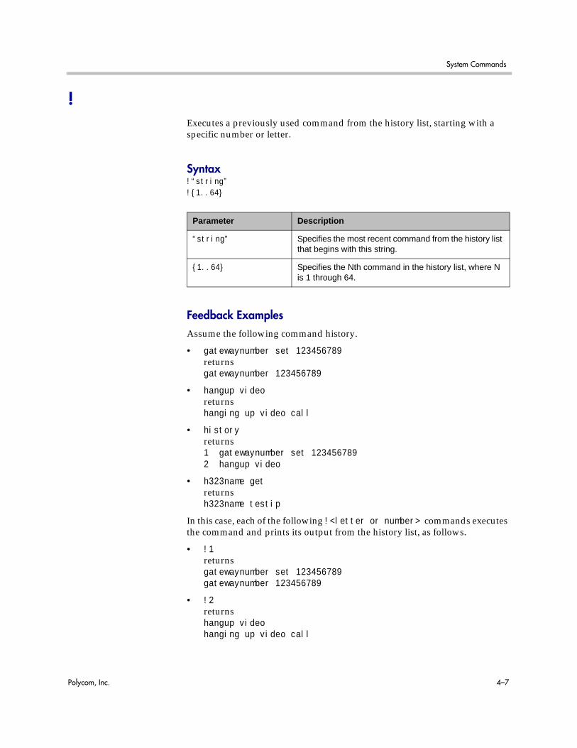
System Commands
Polycom, Inc. 4–7
!Executes a previously used command from the history list, starting with a specific number or letter.
Syntax!“string”!{1..64}
Feedback ExamplesAssume the following command history.
• gatewaynumber set 123456789returnsgatewaynumber 123456789
• hangup videoreturnshanging up video call
• historyreturns1 gatewaynumber set 1234567892 hangup video
• h323name getreturnsh323name testip
In this case, each of the following !<letter or number> commands executes the command and prints its output from the history list, as follows.
• !1returnsgatewaynumber set 123456789gatewaynumber 123456789
• !2returnshangup videohanging up video call
Parameter Description
“string” Specifies the most recent command from the history list that begins with this string.
{1..64} Specifies the Nth command in the history list, where N is 1 through 64.

Integrator’s Reference Manual for Polycom HDX Systems
4–8 Polycom, Inc.
• !hreturnsh323name geth323name testip
• historyreturns1 gatewaynumber set 1234567892 hangup video3 h323name get4 gatewaynumber set 1234567895 hangup video6 h323name get
See AlsoFor information about the history list, refer to history on page 4-177.

System Commands
Polycom, Inc. 4–9
abk (deprecated)Returns local directory (address book) entries. This command has been deprecated. Polycom recommends using the addrbook command on page 4-12.
Syntaxabk allabk batch {0..59}abk batch search “pattern” “count”abk batch define “start_no” “stop_no”abk letter {a..z}abk range “start_no” “stop_no“abk refresh
Parameter Description
all Returns all the entries in the local directory.
batch Returns a batch of 10 local directory entries. Requires a batch number, which must be an integer in the range {0..59}.
search Specifies a batch search.
“pattern” Specifies a pattern to match for the batch search.
“count” Specifies the number of entries to list that match the pattern.
define Returns a batch of entries in the range defined by “start_no” to “stop_no.”
“start_no” Specifies the beginning of the range of entries to return.
“stop_no” Specifies the end of the range of entries to return.
letter Returns entries beginning with the letter specified from the range {a..z}. Requires one or two alphanumeric characters. Valid characters are:
- _ / ; @ , . \
0 through 9
a through z
range Returns local directory entries numbered “start_no” through “stop_no”. Requires two integers.
refresh Gets a more current copy of the local directory.
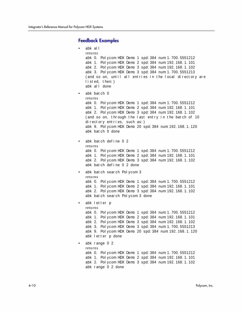
Integrator’s Reference Manual for Polycom HDX Systems
4–10 Polycom, Inc.
Feedback Examples• abk all
returnsabk 0. Polycom HDX Demo 1 spd:384 num:1.700.5551212abk 1. Polycom HDX Demo 2 spd:384 num:192.168.1.101abk 2. Polycom HDX Demo 3 spd:384 num:192.168.1.102abk 3. Polycom HDX Demo 3 spd:384 num:1.700.5551213(and so on, until all entries in the local directory are listed, then:)abk all done
• abk batch 0returnsabk 0. Polycom HDX Demo 1 spd:384 num:1.700.5551212abk 1. Polycom HDX Demo 2 spd:384 num:192.168.1.101abk 2. Polycom HDX Demo 3 spd:384 num:192.168.1.102(and so on, through the last entry in the batch of 10 directory entries, such as:)abk 9. Polycom HDX Demo 20 spd:384 num:192.168.1.120abk batch 0 done
• abk batch define 0 2returnsabk 0. Polycom HDX Demo 1 spd:384 num:1.700.5551212abk 1. Polycom HDX Demo 2 spd:384 num:192.168.1.101abk 2. Polycom HDX Demo 3 spd:384 num:192.168.1.102abk batch define 0 2 done
• abk batch search Polycom 3returnsabk 0. Polycom HDX Demo 1 spd:384 num:1.700.5551212abk 1. Polycom HDX Demo 2 spd:384 num:192.168.1.101abk 2. Polycom HDX Demo 3 spd:384 num:192.168.1.102abk batch search Polycom 3 done
• abk letter preturnsabk 0. Polycom HDX Demo 1 spd:384 num:1.700.5551212abk 1. Polycom HDX Demo 2 spd:384 num:192.168.1.101abk 2. Polycom HDX Demo 3 spd:384 num:192.168.1.102abk 3. Polycom HDX Demo 3 spd:384 num:1.700.5551213abk 9. Polycom HDX Demo 20 spd:384 num:192.168.1.120abk letter p done
• abk range 0 2returnsabk 0. Polycom HDX Demo 1 spd:384 num:1.700.5551212abk 1. Polycom HDX Demo 2 spd:384 num:192.168.1.101abk 2. Polycom HDX Demo 3 spd:384 num:192.168.1.102abk range 0 2 done

System Commands
Polycom, Inc. 4–11
CommentsBeginning in software version 2.5, entries with multiple addresses (for example, an H.323 address and an ISDN number) return each address type on separate lines with an incremented record number. With previous software versions, entries with multiple addresses return each address type with the same record number.
abk entries are entries stored on the system. gabk entries are entries stored on the GDS. In the user interface, the address book and global address book features are referred to as the directory and the global directory.
See AlsoTo return global directory entries, use the gabk (deprecated) command on page 4-136.

Integrator’s Reference Manual for Polycom HDX Systems
4–12 Polycom, Inc.
addrbookReturns local directory (address book) entries.
Syntaxaddrbook alladdrbook batch {0..59}addrbook batch search “pattern” “count”addrbook batch define “start_no” “stop_no”addrbook letter {a..z}addrbook range “start_no” “stop_no”addrbook refresh
Feedback Examples • addrbook all
returnsaddrbook 0. “Polycom HDX Demo 1” isdn_spd:384
Parameter Description
all Returns all the entries in the local directory.
batch Returns a batch of 10 local directory entries. Requires a batch number, which must be an integer in the range {0..59}.
search Specifies a batch search.
“pattern” Specifies a pattern to match for the batch search.
“count” Specifies the number of entries to list that match the pattern.
define Returns a batch of entries in the range defined by “start_no” to “stop_no.”
letter Returns entries beginning with the letter specified from the range {a..z}. Requires one or two alphanumeric characters. Valid characters are:- _ / ; @ , . \ 0 through 9a through z
range Returns local directory entries numbered “start_no” through “stop_no”. Requires two integers.
“start_no” Specifies the beginning of the range of entries to return.
“stop_no” Specifies the end of the range of entries to return.
refresh Gets a more current copy of the local directory.

System Commands
Polycom, Inc. 4–13
isdn_num:1.700.5551212 isdn_ext:addrbook 1. “Polycom HDX Demo 2” h323_spd:384 h323_num:192.168.1.101 h323_ext:7878addrbook 2. “Polycom HDX Demo 3” sip_spd:384 sip_num:[email protected] 3. “Polycom HDX Demo 3” phone_num:1.512.5121212(and so on, until all entries in the local directory are listed, then:)addrbook all done
• addrbook batch 0returnsaddrbook 0. “Polycom HDX Demo 1” isdn_spd:384 isdn_num:1.700.5551212 isdn_ext:addrbook 1. “Polycom HDX Demo 2” h323_spd:384 h323_num:192.168.1.101 h323_ext:7878addrbook 2. “Polycom HDX Demo 3” sip_spd:384 sip_num:[email protected] 3. “Polycom HDX Demo 3” phone_num:1.512.5121212(and so on, through the last entry in the batch of 10 directory entries, such as:)addrbook 9. “Polycom HDX Demo 20” h323_spd:384 h323_num:192.168.1.120 h323_ext:addrbook batch 0 done
• addrbook batch define 0 2returnsaddrbook 0. “Polycom HDX Demo 1” isdn_spd:384 isdn_num:1.700.5551212 isdn_ext:addrbook 1. “Polycom HDX Demo 2” h323_spd:384 h323_num:192.168.1.101 h323_ext:7878addrbook 2. “Polycom HDX Demo 3” sip_spd:384 sip_num:[email protected] batch define 0 2 done
CommentsBeginning in software version 2.5, entries with multiple addresses (for example, an H.323 address and an ISDN number) return each address type on separate lines with an incremented record number. With previous software versions, entries with multiple addresses return each address type with the same record number. addrbook entries are stored in the local directory (address book).

Integrator’s Reference Manual for Polycom HDX Systems
4–14 Polycom, Inc.
addressdisplayedingabSpecifies whether to display the system address in the global directory.
Syntaxaddressdisplayedingab getaddressdisplayedingab privateaddressdisplayedingab public
Feedback Examples• addressdisplayedingab private
returnsaddressdisplayedingab private
• addressdisplayedingab publicreturnsaddressdisplayedingab public
• addressdisplayedingab getreturnsaddressdisplayedingab public
Parameter Description
get Returns the current setting.
private Specifies not to display the system address in the global directory.
public Displays the system address in the global directory.

System Commands
Polycom, Inc. 4–15
advnetstatsGets advanced network statistics for a call connection.
Syntaxadvnetstats [{0..n}]
Feedback Examples• advnetstats 1
returnscall:1 tar:24k rar:24k tvr:64.3k rvr:104ktvru:63.8k rvru:114.6k tvfr:15.0 rvfr:15.0 vfe ---tapl:66 rapl:0 taj:46mS raj:40mS tvpl:122 rvpl:0tvj:21mS rvj:60mS dc:--- rsid:Polycom_4.2 ccaps:E9P
• Returned parameters are:tar=Transmit audio raterar=Receive audio ratetvr=Transmit video ratervr=Receive video ratetvru=Transmit video rate usedrvru=Receive video rate usedtvfr=Transmit video frame ratervfr=Receive video frame ratevfe=Video FEC errorstapl=Transmit audio packet loss (H.323 calls only) tlsdp=Transmit LSD protocol (H.320 calls only) rapl=Receive audio packet loss (H.323 calls only) rlsdp=Receive LSD protocol (H.320 calls only) taj=Transmit audio jitter (H.323 calls only) tlsdr=Transmit LSD rate (H.320 calls only) raj=Receive audio jitter (H.323 calls only) rlsd=Receive LSD rate (H.320 calls only) tvpl=Transmit video packet loss (H.323 calls only)tmlpp=Transmit MLP protocol (H.320 calls only) rvpl=Receive video packet loss (H.323 calls only)
Parameter Description
{0..n} Specifies a connection in a multipoint call, where n is the maximum number of connections supported by the system. 0 is call #1, 1 is call #2, 2 is call #3, and so on. Select a number from this range to specify a remote site call for which you want to obtain advanced network statistics.
Omit this parameter when retrieving statistics for a point-to-point call.

Integrator’s Reference Manual for Polycom HDX Systems
4–16 Polycom, Inc.
rmlpp=Receive MLP protocol (H.320 calls only) tvj=Transmit video jitter (H.323 calls only) tmlpr=Transmit MLP rate (H.320 calls only) rvj=Receive video jitter (H.323 calls only)rmlpr=Receive MLP rate (H.320 calls only) dc=Encryption informationrsid=Remote system idccaps=Content capability, where possible responses include “9” (H.239), “E” (enterprise dual streams), “N” (none), and “P” (content over the people stream)
See AlsoTo return network statistics for a call, use the netstats command on page 4-249.

System Commands
Polycom, Inc. 4–17
alertusertoneSets or gets the tone used for user alerts.
Syntaxalertusertone <get|1|2|3|4>
Feedback Examples• alertusertone 1
returnsalertusertone 1
• alertusertone getreturnsalertusertone 1
Parameter Description
get Returns the current setting.
1|2|3|4 Sets the user alert to the corresponding tone.

Integrator’s Reference Manual for Polycom HDX Systems
4–18 Polycom, Inc.
alertvideotoneSets the tone used for incoming video calls.
Syntaxalertvideotone <get|1|2|3|4|5|6|7|8|9|10>
Feedback Examples• alertvideotone 1
returnsalertvideotone 1
• alertvideotone getreturnsalertvideotone 1
Parameter Description
get Returns the current setting.
1|2|3|4|5|6|7|8|9|10 Sets the incoming video alert to the corresponding tone.

System Commands
Polycom, Inc. 4–19
all registerRegisters for most commonly-used user registration events.
Syntaxall register
Feedback Examples• all register
returnscallstate registeredcamera registeredchaircontrol registeredlinestate registeredmute registeredpip registeredpopupinfo registeredpreset registeredscreen registeredvcbutton registeredvolume registeredsleep registered
CommentsRegisters changes to any of the following types of parameters:
• Current near-site or far-site source
• State of privacy
• Current volume level
• Active camera presets
• Status of point-to-point or multipoint calls
• Status of physical ISDN/IP connection to codec
• PIP state
• Chair control
• System information
This command is particularly useful when two different control systems are being used simultaneously, such as the web and API commands. The system maintains the registration changes through restarts.
To register for events not included in this feedback, refer to the specific registration command.
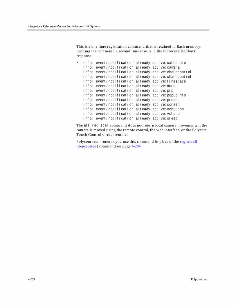
Integrator’s Reference Manual for Polycom HDX Systems
4–20 Polycom, Inc.
This is a one time registration command that is retained in flash memory. Sending the command a second time results in the following feedback response:
• info: event/notification already active:callstateinfo: event/notification already active:camerainfo: event/notification already active:chaircontrolinfo: event/notification already active:chaircontrolinfo: event/notification already active:linestateinfo: event/notification already active:muteinfo: event/notification already active:pipinfo: event/notification already active:popupinfoinfo: event/notification already active:presetinfo: event/notification already active:screeninfo: event/notification already active:vcbuttoninfo: event/notification already active:volumeinfo: event/notification already active:sleep
The all register command does not return local camera movements if the camera is moved using the remote control, the web interface, or the Polycom Touch Control virtual remote.
Polycom recommends you use this command in place of the registerall (deprecated) command on page 4-284.

System Commands
Polycom, Inc. 4–21
all unregisterSimultaneously unregisters all registered user feedback so that the API no longer reports changes to the parameters.
Syntaxall unregister
Feedback Examples• all unregister
returnscallstate unregisteredcamera unregisteredchaircontrol unregisteredlinestate unregisteredchaircontrol unregisteredmute unregisteredpip unregisteredpopupinfo unregisteredpreset unregisteredscreen unregisteredvcbutton unregisteredvolume unregisteredsleep unregistered
CommentsThe following types of parameters are unregistered:
• Current near-site or far-site source
• State of privacy
• Current volume level
• Active camera presets
• Status of point-to-point or multipoint calls
• Status of physical ISDN/IP connection to codec
• PIP state
• Chair control
• System information
Polycom recommends you use this command in place of the unregisterall (deprecated) command on page 4-333.
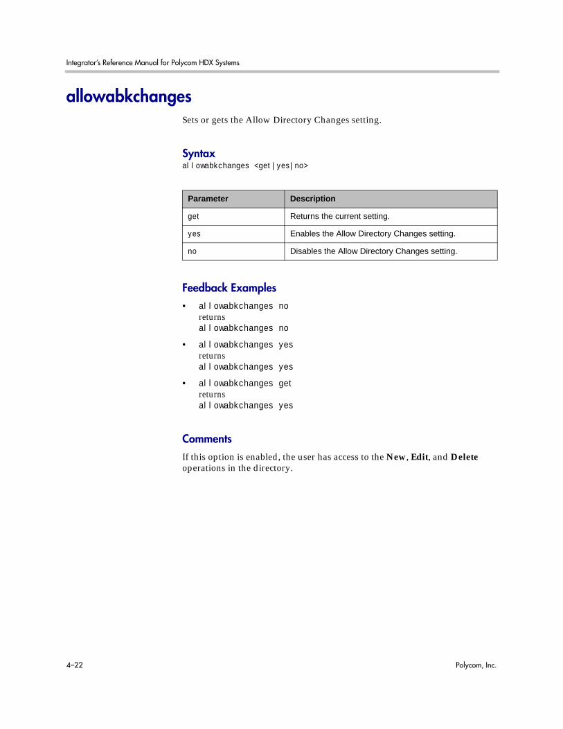
Integrator’s Reference Manual for Polycom HDX Systems
4–22 Polycom, Inc.
allowabkchangesSets or gets the Allow Directory Changes setting.
Syntaxallowabkchanges <get|yes|no>
Feedback Examples• allowabkchanges no
returnsallowabkchanges no
• allowabkchanges yesreturnsallowabkchanges yes
• allowabkchanges getreturnsallowabkchanges yes
CommentsIf this option is enabled, the user has access to the New, Edit, and Delete operations in the directory.
Parameter Description
get Returns the current setting.
yes Enables the Allow Directory Changes setting.
no Disables the Allow Directory Changes setting.

System Commands
Polycom, Inc. 4–23
allowcamerapresetssetupSets or gets whether users are allowed to change camera presets.
Syntaxallowcamerapresetssetup <get|yes|no>
Feedback Examples• allowcamerapresetssetup no
returnsallowcamerapresetssetup no
• allowcamerapresetssetup yesreturnsallowcamerapresetssetup yes
• allowcamerapresetssetup getreturnsallowcamerapresetssetup yes
Parameter Description
get Returns the current setting.
yes Allows users to change camera presets.
no Prevents users from changing camera presets.

Integrator’s Reference Manual for Polycom HDX Systems
4–24 Polycom, Inc.
allowdialingSets or gets the ability to dial out from the system.
Syntaxallowdialing <get|yes|no>
Feedback Examples• allowdialing no
returnsallowdialing no
• allowdialing yesreturnsallowdialing yes
• allowdialing getreturnsallowdialing yes
Commentsallowdialing no removes the dialing field and marquee text from the Home screen.
Parameter Description
get Returns the current setting.
yes Allows users to place calls.
no Disables dialing so that the system can only receive calls.

System Commands
Polycom, Inc. 4–25
allowmixedcallsSets or gets the ability to place and receive mixed protocol multipoint calls (IP and ISDN). It allows the administrator to disable this ability for security reasons.
Syntaxallowmixedcalls <get|yes|no>
Feedback Examples• allowmixedcalls no
returnsallowmixedcalls no
• allowmixedcalls yesreturnsallowmixedcalls yes
• allowmixedcalls getreturnsallowmixedcalls yes
Parameter Description
get Returns the current setting.
yes Enables mixed IP and ISDN calls.
no Disables mixed IP and ISDN calls.
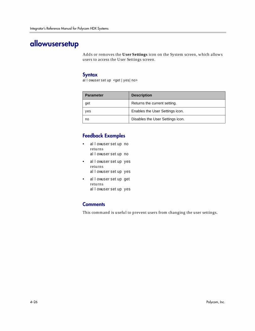
Integrator’s Reference Manual for Polycom HDX Systems
4–26 Polycom, Inc.
allowusersetupAdds or removes the User Settings icon on the System screen, which allows users to access the User Settings screen.
Syntaxallowusersetup <get|yes|no>
Feedback Examples• allowusersetup no
returnsallowusersetup no
• allowusersetup yesreturnsallowusersetup yes
• allowusersetup getreturnsallowusersetup yes
CommentsThis command is useful to prevent users from changing the user settings.
Parameter Description
get Returns the current setting.
yes Enables the User Settings icon.
no Disables the User Settings icon.

System Commands
Polycom, Inc. 4–27
amxddSets or gets the AMX Device Discovery beacon.
Syntaxamxdd getamxdd <on|off>
Feedback Examples• amxdd get
returnsamxdd off
• amxdd onreturnsamxdd on
CommentsThe default setting for this signal is “off”.
Turning on this command sends out the AMX Device Discovery beacon over the LAN interface. On serial port API sessions, a similar feature is always enabled. This command does not affect that feature on serial port API sessions.
Parameter Description
get Returns the current setting.
on Turns on the AMX Device Discovery beacon.
off Turns off the AMX Device Discovery beacon.
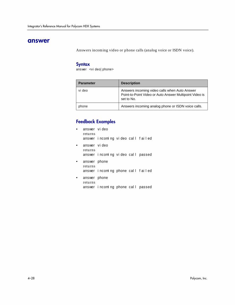
Integrator’s Reference Manual for Polycom HDX Systems
4–28 Polycom, Inc.
answerAnswers incoming video or phone calls (analog voice or ISDN voice).
Syntaxanswer <video|phone>
Feedback Examples• answer video
returnsanswer incoming video call failed
• answer videoreturnsanswer incoming video call passed
• answer phonereturnsanswer incoming phone call failed
• answer phonereturnsanswer incoming phone call passed
Parameter Description
video Answers incoming video calls when Auto Answer Point-to-Point Video or Auto Answer Multipoint Video is set to No.
phone Answers incoming analog phone or ISDN voice calls.

System Commands
Polycom, Inc. 4–29
areacodeSets or gets the area code for all ISDN lines. This command is only applicable if you have a network interface connected to your system.
Syntaxareacode getareacode set “areacode”
Feedback Examples• areacode set 212
returnsareacode 212
• areacode getreturnsareacode 212
CommentsThis area code is associated with the area where the system is used.
Parameter Description
get Returns the area code information.
set Sets the ISDN area code when followed by the area code parameter. To erase the current setting, omit “areacode”.
“areacode” Area code to use for all lines.
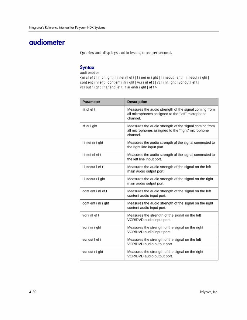
Integrator’s Reference Manual for Polycom HDX Systems
4–30 Polycom, Inc.
audiometerQueries and displays audio levels, once per second.
Syntaxaudiometer <micleft|micright|lineinleft|lineinright|lineoutleft|lineoutright|contentinleft|contentinright|vcrinleft|vcrinright|vcroutleft|vcroutright|farendleft|farendright|off>
Parameter Description
micleft Measures the audio strength of the signal coming from all microphones assigned to the “left” microphone channel.
micright Measures the audio strength of the signal coming from all microphones assigned to the “right” microphone channel.
lineinright Measures the audio strength of the signal connected to the right line input port.
lineinleft Measures the audio strength of the signal connected to the left line input port.
lineoutleft Measures the audio strength of the signal on the left main audio output port.
lineoutright Measures the audio strength of the signal on the right main audio output port.
contentinleft Measures the audio strength of the signal on the left content audio input port.
contentinright Measures the audio strength of the signal on the right content audio input port.
vcrinleft Measures the strength of the signal on the left VCR/DVD audio input port.
vcrinright Measures the strength of the signal on the right VCR/DVD audio input port.
vcroutleft Measures the strength of the signal on the left VCR/DVD audio output port.
vcroutright Measures the strength of the signal on the right VCR/DVD audio output port.
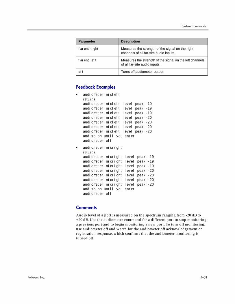
System Commands
Polycom, Inc. 4–31
Feedback Examples• audiometer micleft
returnsaudiometer micleft level peak:-19audiometer micleft level peak:-19audiometer micleft level peak:-19audiometer micleft level peak:-20audiometer micleft level peak:-20audiometer micleft level peak:-20audiometer micleft level peak:-20and so on until you enteraudiometer off
• audiometer micrightreturnsaudiometer micright level peak:-19audiometer micright level peak:-19audiometer micright level peak:-19audiometer micright level peak:-20audiometer micright level peak:-20audiometer micright level peak:-20audiometer micright level peak:-20and so on until you enteraudiometer off
CommentsAudio level of a port is measured on the spectrum ranging from -20 dB to +20 dB. Use the audiometer command for a different port to stop monitoring a previous port and to begin monitoring a new port. To turn off monitoring, use audiometer off and watch for the audiometer off acknowledgement or registration response, which confirms that the audiometer monitoring is turned off.
farendright Measures the strength of the signal on the right channels of all far-site audio inputs.
farendleft Measures the strength of the signal on the left channels of all far-site audio inputs.
off Turns off audiometer output.
Parameter Description

Integrator’s Reference Manual for Polycom HDX Systems
4–32 Polycom, Inc.
audiotransmitlevelSets or gets the audio volume transmitted to the far site, or notification of transmit level changes.
Syntaxaudiotransmitlevel <get|up|down|register|unregister>audiotransmitlevel set {-20..30}
Feedback Examples• audiotransmitlevel set 2
returnsaudiotransmitlevel 2
• audiotransmitlevel getreturnsaudiotransmitlevel 2
• audiotransmitlevel upreturnsaudiotransmitlevel 3
• audiotransmitlevel downreturnsaudiotransmitlevel 2
• audiotransmitlevel registerreturnsaudiotransmitlevel registered
Parameter Description
get Returns the current setting.
up Sets the volume 1 decibel higher than the current setting.
down Sets the volume 1 decibel lower than the current setting.
register Registers to receive notification when audio transmit level changes.
unregister Unregisters to receive notification when audio transmit level changes.
set Sets the volume to the specified dB level. Valid values are: {-20..30}.

System Commands
Polycom, Inc. 4–33
• audiotransmitlevel unregisterreturnsaudiotransmitlevel unregistered

Integrator’s Reference Manual for Polycom HDX Systems
4–34 Polycom, Inc.
autoanswerSets or gets the Auto Answer Point-to-Point Video mode, which determines how the system handles an incoming call in a point-to-point video conference.
Syntaxautoanswer <get|yes|no|donotdisturb>
Feedback Examples• autoanswer yes
returnsautoanswer yes
• autoanswer noreturnsautoanswer no
• autoanswer getreturnsautoanswer no
• autoanswer donotdisturbreturnsautoanswer donotdisturb
CommentsIf autoanswer is set to no or donotdisturb, you must rely on API session notifications to answer inbound calls.
Parameter Description
yes Allows any incoming video call to be connected automatically. This is the default setting.
no Prompts the user to answer incoming video calls.
donotdisturb Notifies the user of incoming calls, but does not connect the call. The site that placed the call receives a Far Site Busy (H.320) or Call Rejected (H.323) code.
get Returns the current setting.

System Commands
Polycom, Inc. 4–35
autoshowcontentSpecifies whether to send content automatically when a computer is connected to the system.
Syntaxautoshowcontent <get|on|off>
Feedback Examples• autoshowcontent on
returnsautoshowcontent on
• autoshowcontent offreturnsautoshowcontent off
• autoshowcontent getreturnsautoshowcontent off
Parameter Description
get Returns the current setting.
on Sets the system to send content automatically when a computer is connected to the system.
off Sets the system to not send content automatically.

Integrator’s Reference Manual for Polycom HDX Systems
4–36 Polycom, Inc.
backlightcompensationSets or gets the Backlight Compensation mode.
Syntaxbacklightcompensation <get|yes|no>
Feedback Examples• backlightcompensation yes
returnsbacklightcompensation yes
• backlightcompensation noreturnsbacklightcompensation no
• backlightcompensation getreturnsbacklightcompensation no
Parameter Description
get Returns the current setting.
yes Enables Backlight Compensation. The camera automatically adjusts for a bright background.
no Disables the option.

System Commands
Polycom, Inc. 4–37
basicmodeSets or gets the Basic Mode configuration, a limited operating mode that uses H.261 for video and G.711 for audio. Basic mode provides administrators with a workaround for interoperability issues that cannot be solved using other methods.
Syntaxbasicmode <get|on|off>
Feedback Examples• basicmode on
returnsbasicmode on
• basicmode offreturnsbasicmode off
• basicmode getreturnsbasicmode off
Parameter Description
get Returns the current setting.
on Enables basic mode.
off Disables basic mode.

Integrator’s Reference Manual for Polycom HDX Systems
4–38 Polycom, Inc.
bri1enable, bri2enable, bri3enable, bri4enableSets or gets the configuration of the specified ISDN BRI line. This command is only applicable if you have a BRI network interface connected to your system.
Syntaxbri1enable <get|yes|no>bri2enable <get|yes|no>bri3enable <get|yes|no>bri4enable <get|yes|no>
Feedback Examples• bri1enable yes
returnsbri1enable yes
• bri1enable noreturnsbri1enable no
• bri1enable getreturnsbri1enable no
Parameter Description
get Returns the status of the BRI line—yes if enabled, no if disabled.
yes Enables the BRI line.
no Disables the BRI line.

System Commands
Polycom, Inc. 4–39
briallenableSets or gets the configuration of all ISDN BRI lines. This command is only applicable if you have a BRI network interface connected to your system.
Syntaxbriallenable <get|yes|no>
Feedback Examples• briallenable yes
returnsbri1enable yesbri2enable yesbri3enable yesbri4enable yes
• briallenable noreturnsbri1enable nobri2enable nobri3enable nobri4enable no
• briallenable getreturnsbri1enable nobri2enable nobri3enable nobri4enable no
Commentsbriallenable yes only enables lines where the directory numbers have been populated.
Parameter Description
get Returns the status of all BRI lines—yes if enabled, no if disabled.
yes Enables all BRI lines.
no Disables all BRI lines.

Integrator’s Reference Manual for Polycom HDX Systems
4–40 Polycom, Inc.
buttonSimulates Polycom remote control buttons.
Syntaxbutton <#|*|0|1|2|3|4|5|6|7|8|9|.>button <down|left|right|select|up>button <auto|back|call|far|graphics|hangup|near>button <help|mute|volume+|volume-|lowbattery|zoom+|zoom->button <pickedup|putdown>button <camera|delete|directory|home|keyboard|period|pip|preset>button <info|menu|slides|option>button “valid_button” [“valid_button” ...]button <mmstop|mmplay|mmpause|mmrecord|mmforward|mmrewind>
Parameter Description
. Types a period (dot) if the cursor is on a text field.
# Sends the # button signal to the user interface.
* Sends the * button signal to the user interface.
[“valid_button” ...] Sends one or more remote control button signals.
0|1|2|3|4|5|6|7|8|9 Sends the corresponding numeric button signal to the user interface.
auto Sends the Auto button signal to the user interface.
back Simulates the Back button on multiple-page screens.
call Sends the Call button signal to the user interface.
camera Sends the Camera button signal to the user interface.
delete Sends the Delete button signal to the user interface.
directory Sends the Directory button signal to the user interface.
down Sends the down arrow button signal to the user interface.
far Sends the Far button signal to the user interface.
graphics Sends the Content button signal to the user interface.
hangup Sends the Hang Up button signal to the user interface.
help Sends the Help button signal to the user interface.
home Sends the Home button signal to the user interface.
info Sends the Info button signal to the user interface.

System Commands
Polycom, Inc. 4–41
keyboard Brings up the on-screen keyboard if the cursor is on a text field.
left Sends the left arrow button signal to the user interface.
lowbattery Simulates a low battery alert for the remote control.
menu Sends the Menu button signal to legacy systems. Deprecated. Polycom recommends using back instead of this button.
mmstop Stops the video stream on the RSS-4000™.
mmplay Plays the video stream on the RSS-4000.
mmpause Pauses the video stream on the RSS-4000.
mmrecord Records the video stream on the RSS-4000.
mmforward Fast forwards the video stream on the RSS-4000.
mmrewind Rewinds the video stream on the RSS-4000.
mute Sends the Mute button signal to the user interface, causing a toggle of mute state.
near Sends the Near button signal to the user interface.
option Sends the Option button signal to the user interface.
period Types a period (dot) if the cursor is on a text field.
pickedup Sends a signal indicating that the remote control has been picked up.
pip Sends the Display button signal to the user interface.
preset Sends the Preset button signal to the user interface.
putdown Sends a signal indicating that the remote control has been set down.
right Sends the right arrow button signal to the user interface.
select Sends the Select (center button) button signal to the user interface.
slides Sends the Slides button signal to legacy systems. Deprecated. Polycom recommends using graphics instead of this button.
up Sends the up arrow button signal to the user interface.
volume- Sends the volume - button signal to the user interface.
Parameter Description
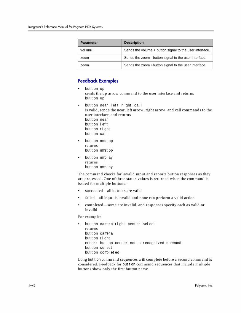
Integrator’s Reference Manual for Polycom HDX Systems
4–42 Polycom, Inc.
Feedback Examples• button up
sends the up arrow command to the user interface and returnsbutton up
• button near left right callis valid, sends the near, left arrow, right arrow, and call commands to the user interface, and returnsbutton nearbutton leftbutton rightbutton call
• button mmstopreturnsbutton mmstop
• button mmplayreturnsbutton mmplay
The command checks for invalid input and reports button responses as they are processed. One of three status values is returned when the command is issued for multiple buttons:
• succeeded—all buttons are valid
• failed—all input is invalid and none can perform a valid action
• completed—some are invalid, and responses specify each as valid or invalid
For example:
• button camera right center selectreturnsbutton camerabutton righterror: button center not a recognized commandbutton selectbutton completed
Long button command sequences will complete before a second command is considered. Feedback for button command sequences that include multiple buttons show only the first button name.
volume+ Sends the volume + button signal to the user interface.
zoom- Sends the zoom - button signal to the user interface.
zoom+ Sends the zoom +button signal to the user interface.
Parameter Description

System Commands
Polycom, Inc. 4–43
CommentsSeveral parameters can be combined in the same command in any order.
The button commands are not recommended. When possible, use another API command instead of the button commands, which rely on the current organization of the user interface.
Use button pip to send the Display button signal to the user interface.
Feedback responses from RSS-2000 parameters are not from the RSS-2000 and are not an indication that you are in control of the RSS-2000. You can issue the commands when you are not connected to the RSS-2000 and still receive feedback.

Integrator’s Reference Manual for Polycom HDX Systems
4–44 Polycom, Inc.
calendardomainGets and sets the domain used by the calendaring service to log in to the Microsoft® Exchange server.
Syntaxcalendardomain getcalendardomain “domain”
Feedback Examples• calendardomain get
returnscalendardomain smithfield
• calendardomain fairviewreturnscalendardomain fairview
See AlsoTo enable or disable the calendaring service, use the calendarregisterwithserver command on page 4-52. To configure the Microsoft Exchange server address used by this service use the calendarserver command on page 4-55. To set the resource mailbox to be monitored, use the calendarresource command on page 4-54.
Parameter Description
get Returns the domain used by the calendaring service.
“domain” The domain to be used by the calendaring service.

System Commands
Polycom, Inc. 4–45
calendarmeetingsRetrieves scheduled meetings within the given time span or with the given meeting ID.
Syntaxcalendarmeetings list “starttime” [“endtime”]calendarmeetings info “meetingid”
Parameter Description
list Returns the meeting id or ids for meetings that start at or after the specified start time and end time.
“starttime” The start time of meetings to be retrieved.
The start time can be entered in one of the following formats:
• YYYY-MM-DD:HH:MM
• today:HH:MM
• today
• tomorrow:HH:MM
• tomorrow
The times are interpreted to be local times in the time zone the system was configured for.
“endtime” The end time of meetings to be retrieved.
This parameter can be given in the following format.
• YYYY-MM-DD:HH:MM
• today:HH:MM
• today
• tomorrow:HH:MM
• tomorrow
The times are interpreted to be local times in the time zone the system was configured for.
info Retrieves meeting details for scheduled meetings when the Polycom HDX system is registered with the calendaring service. Returns information such as the location, subject and organizer of the meeting.
“meetingid” The ID of the meeting for which you want to find details.
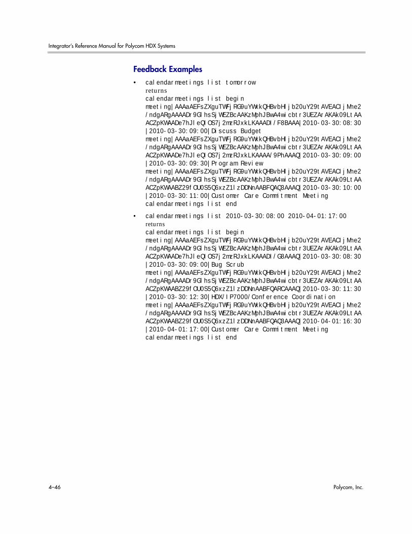
Integrator’s Reference Manual for Polycom HDX Systems
4–46 Polycom, Inc.
Feedback Examples• calendarmeetings list tomorrow
returnscalendarmeetings list begin meeting|AAAaAEFsZXguTWFjRG9uYWxkQHBvbHljb20uY29tAVEACIjMne2/ndgARgAAAADr9GlhsSjWEZBcAAKzMphJBwA4wicbtr3UEZArAKAk09LtAAACZpKWAADe7hJleQIOS7j2mzRJxkLKAAADI/F8BAAA|2010-03-30:08:30|2010-03-30:09:00|Discuss Budgetmeeting|AAAaAEFsZXguTWFjRG9uYWxkQHBvbHljb20uY29tAVEACIjMne2/ndgARgAAAADr9GlhsSjWEZBcAAKzMphJBwA4wicbtr3UEZArAKAk09LtAAACZpKWAADe7hJleQIOS7j2mzRJxkLKAAAA/9PhAAAQ|2010-03-30:09:00|2010-03-30:09:30|Program Review meeting|AAAaAEFsZXguTWFjRG9uYWxkQHBvbHljb20uY29tAVEACIjMne2/ndgARgAAAADr9GlhsSjWEZBcAAKzMphJBwA4wicbtr3UEZArAKAk09LtAAACZpKWAABZ29fOU0S5Q6xzZ1lzDDNnAABFQAQ3AAAQ|2010-03-30:10:00|2010-03-30:11:00|Customer Care Commitment Meetingcalendarmeetings list end
• calendarmeetings list 2010-03-30:08:00 2010-04-01:17:00returnscalendarmeetings list begin meeting|AAAaAEFsZXguTWFjRG9uYWxkQHBvbHljb20uY29tAVEACIjMne2/ndgARgAAAADr9GlhsSjWEZBcAAKzMphJBwA4wicbtr3UEZArAKAk09LtAAACZpKWAADe7hJleQIOS7j2mzRJxkLKAAADI/G8AAAQ|2010-03-30:08:30|2010-03-30:09:00|Bug Scrubmeeting|AAAaAEFsZXguTWFjRG9uYWxkQHBvbHljb20uY29tAVEACIjMne2/ndgARgAAAADr9GlhsSjWEZBcAAKzMphJBwA4wicbtr3UEZArAKAk09LtAAACZpKWAABZ29fOU0S5Q6xzZ1lzDDNnAABFQARCAAAQ|2010-03-30:11:30|2010-03-30:12:30|HDX/IP7000/Conference Coordinationmeeting|AAAaAEFsZXguTWFjRG9uYWxkQHBvbHljb20uY29tAVEACIjMne2/ndgARgAAAADr9GlhsSjWEZBcAAKzMphJBwA4wicbtr3UEZArAKAk09LtAAACZpKWAABZ29fOU0S5Q6xzZ1lzDDNnAABFQAQ3AAAQ|2010-04-01:16:30|2010-04-01:17:00|Customer Care Commitment Meetingcalendarmeetings list end

System Commands
Polycom, Inc. 4–47
• calendarmeetings info AAAaAEFsZXguTWFjRG9uYWxkQHBvbHljb20uY29tAVEACIjMne2/ndgARgAAAADr9GlhsSjWEZBcAAKzMphJBwA4wicbtr3UEZArAKAk09LtAAACZpKWAADe7hJleQIOS7j2mzRJxkLKAAADI/G8AAAQreturnscalendarmeetings info startid|AAAaAEFsZXguTWFjRG9uYWxkQHBvbHljb20uY29tAVEACIjMne2/ndgARgAAAADr9GlhsSjWEZBcAAKzMphJBwA4wicbtr3UEZArAKAk09LtAAACZpKWAADe7hJleQIOS7j2mzRJxkLKAAADI/G8AAAQ2010-03-30:08:30|2010-03-30:09:00|dialable|publicorganizer|Russell Belllocation|Russell's RMX Meeting Room - IP Video Number: 123456 (if registered to corp GK); 888-123-4567/978-123-4567 with passcode: #760900subject|Bug Scrubdialingnumber|video|[email protected]|sipdialingnumber|video|733397|h323dialingnumber|audio|48527meetingpassword|noneattendee|Russell Bellattendee|Rebecca Sharpcalendarmeetings info end
• calendarmeetings info AAAaAEFsZXguTWFjRG9uYWxkQHBvbHljb20uY29tAVEACIjMn4AUcVgARgAAAADr9GlhsSjWEZBcAAKzMphJBwA4wicbtr3UEZArAKAk09LtAAACZpKWAADe7hJleQIOS7j2mzRJxkLKAAAA30GwAAAQreturnscalendarmeetings info startid|AAAaAEFsZXguTWFjRG9uYWxkQHBvbHljb20uY29tAVEACIjMn4AUcVgARgAAAADr9GlhsSjWEZBcAAKzMphJBwA4wicbtr3UEZArAKAk09LtAAACZpKWAADe7hJleQIOS7j2mzRJxkLKAAAA30GwAAAQ2010-04-01:10:30|2010-04-01:11:00|nondialable|privateorganizer|Rebecca Sharplocation|Red River conference roomsubject|Escalations Reviewattendee|Roslin Adamattendee|Conf.AUS.Red Riverattendee|Claudia Nevarezcalendarmeetings info end

Integrator’s Reference Manual for Polycom HDX Systems
4–48 Polycom, Inc.
CommentsIf the meeting’s end time is more than 31 days from the meeting’s start time, the response is shortened to starttime+31days, and meetings that start in that time span are returned.
If an API client is logged in with user-level credentials and if the Polycom HDX system is configured to hide private meeting information on the web interface, the API hides the information from the API client and shows the subject of the meeting as "Private Meeting"; for example:calendarmeetings list beginmeeting|AAAaAEFsZXguTWFjRG9uYWxkQHBvbHljb20uY29tAVEACIjMn4AUcVgARgAAAADr9GlhsSjWEZBcAAKzMphJBwA4wicbtr3UEZArAKAk09LtAAACZpKWAADe7hJleQIOS7j2mzRJxkLKAAAA30GwAAAQ|2009-09-25:08:30|2009-09-25:09:15|private meetingcalendarmeetings list end
If a Polycom HDX system is configured to provide private meeting information on the web interface, the API provides the same information to the API client; for example:calendarmeetings list beginmeeting|AAAZAGV4Y2H1C2VYMDFACJEZLNZZZY5SB2NHBDIARGAAAAAAKQKC8WW3CUWGCPM+AP66WQCASOLXUYMOMEKYBQJJ1Z0MBWASDQANHQAASOLXUYMOMEKYBQJJ1Z0MBWASDQASVGAA|2009-09-25:08:30|2009-09-25:09:15| Democalendarmeetings list end
If the API client is logged in with admin-level credentials, the API provides private meeting information to the API client, regardless of the HDX configuration for displaying private meeting information; for example:calendarmeetings list beginmeeting|AAAZAGV4Y2H1C2VYMDFACJEZLNZZZY5SB2NHBDIARGAAAAAAKQKC8WW3CUWGCPM+AP66WQCASOLXUYMOMEKYBQJJ1Z0MBWASDQANHQAASOLXUYMOMEKYBQJJ1Z0MBWASDQASVGAA|2009-09-25:08:30|2009-09-25:09:15|Release planmeeting|AAAZAGV4Y2H1C2VYMDFACJEZLNZZZY5SB2NHBDIARGAAAAAAKQKC8WW3CUWGCPM+AP66WQCASOLXUYMOMEKYBQJJ1Z0MBWASDQANHQAASOLXUYMOMEKYBQJJ1Z0MBWASDQASVGAA|2009-09-23:11:00|2009-09-23:11:45|Product roadmap for 2010calendarmeetings list end
The calendaring service must be registered with Microsoft Exchange server for the calendarmeetings command to work successfully. If the calendar credentials are invalid, the server address is not valid, or the configured user credentials don't have access permissions to the resource mailbox calendar, the service will fail to register.
This command has multi line output.

System Commands
Polycom, Inc. 4–49
The following characters in the meeting subject will not be displayed:
• | (vertical bar)
• CR (carriage return)
• LF (line feed)
See AlsoTo enable or disable the calendaring service, use the calendarregisterwithserver command on page 4-52. To configure the Microsoft Exchange server address used by this service use the calendarserver command on page 4-55.

Integrator’s Reference Manual for Polycom HDX Systems
4–50 Polycom, Inc.
calendarpasswordSets the password used by the calendaring service to log in to the Microsoft Exchange server.
Syntaxcalendarpassword “password”
Feedback Examplescalendarpassword Dsca1end@rreturnscalendarpassword Dsca1end@r
CommentsThe password can be up to 15 characters long and is case-sensitive. Use strong passwords that combine uppercase and lowercase letters, numbers, and symbols.
See Also To enable or disable the calendaring service, use the calendarregisterwithserver command on page 4-52.
Parameter Description
“password” The password used by the calendaring service to log in to the Microsoft Exchange server.
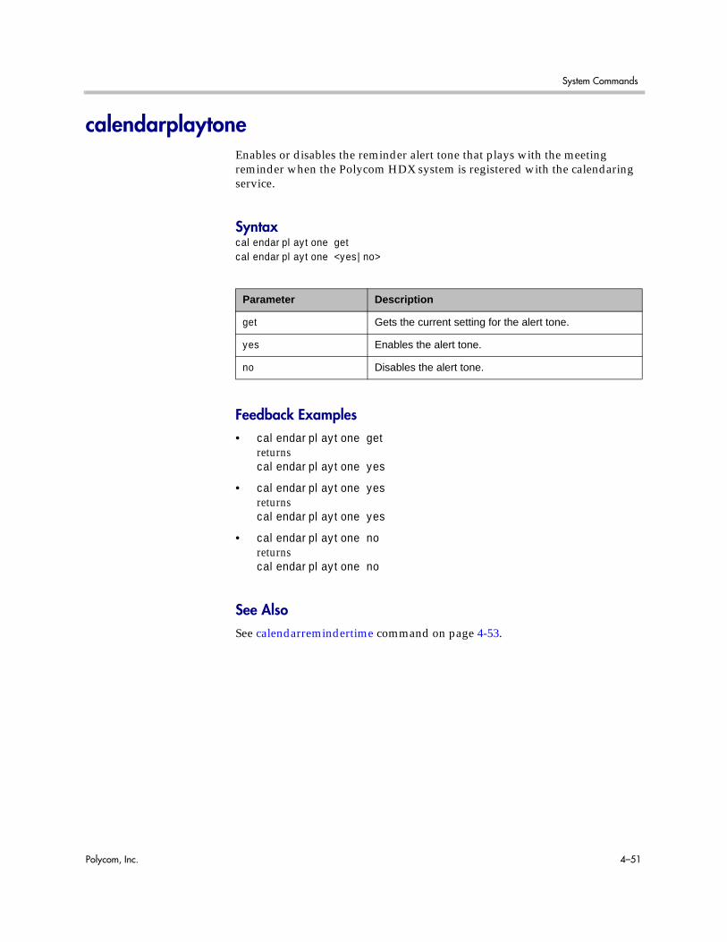
System Commands
Polycom, Inc. 4–51
calendarplaytoneEnables or disables the reminder alert tone that plays with the meeting reminder when the Polycom HDX system is registered with the calendaring service.
Syntaxcalendarplaytone getcalendarplaytone <yes|no>
Feedback Examples• calendarplaytone get
returnscalendarplaytone yes
• calendarplaytone yesreturnscalendarplaytone yes
• calendarplaytone noreturnscalendarplaytone no
See AlsoSee calendarremindertime command on page 4-53.
Parameter Description
get Gets the current setting for the alert tone.
yes Enables the alert tone.
no Disables the alert tone.

Integrator’s Reference Manual for Polycom HDX Systems
4–52 Polycom, Inc.
calendarregisterwithserverEnables or disables the calendaring service.
Syntaxcalendarregisterwithserver getcalendarregisterwithserver <yes|no>
Feedback Examples• calendarregisterwithserver get
returnscalendarregisterwithserver no
• calendarregisterwithserver yesreturnscalendarregisterwithserver yes
• calendarregisterwithserver noreturnscalendarregisterwithserver no
CommentsTo configure the Microsoft Exchange server address used by the calendaring service use the calendarserver command on page 4-55.
Parameter Description
get Returns the current server registration status.
yes Enables the calendaring service.
no Disables the calendaring service.

System Commands
Polycom, Inc. 4–53
calendarremindertimeGets and sets the reminder time for meetings in the calendar when the system is registered with the calendaring service.
Syntaxcalendarremindertime <get|1|5|10|15|30|none>
Feedback Examples• calendarremindertime get
returnscalendarremindertime 5
• calendarremindertime 15returnscalendarremindertime 15
• calendarremindertime nonereturnscalendarremindertime none
CommentsBy default, the reminder time is set to 5 minutes.
See AlsoUse the notify command on page 4-251 to register for meeting reminders.
See also calendarplaytone command on page 4-51.
Parameter Description
get Gets the current reminder time.
1|5|10|15|30|none The number of minutes before a meeting starts that a meeting reminder is given.
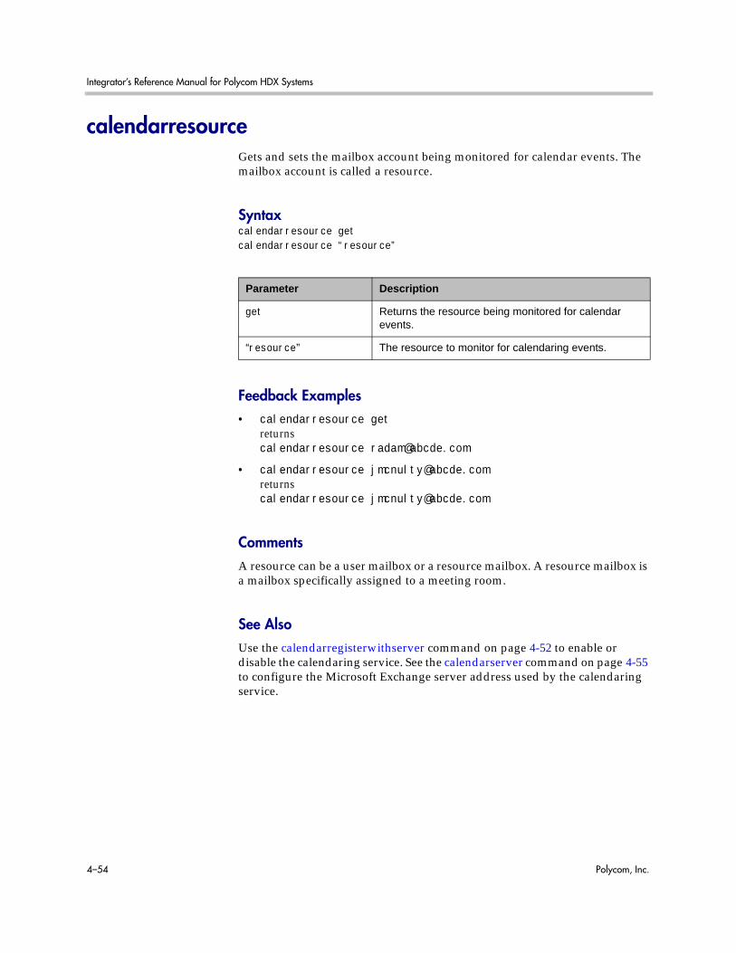
Integrator’s Reference Manual for Polycom HDX Systems
4–54 Polycom, Inc.
calendarresourceGets and sets the mailbox account being monitored for calendar events. The mailbox account is called a resource.
Syntaxcalendarresource getcalendarresource “resource”
Feedback Examples• calendarresource get
returnscalendarresource [email protected]
• calendarresource [email protected] [email protected]
CommentsA resource can be a user mailbox or a resource mailbox. A resource mailbox is a mailbox specifically assigned to a meeting room.
See AlsoUse the calendarregisterwithserver command on page 4-52 to enable or disable the calendaring service. See the calendarserver command on page 4-55 to configure the Microsoft Exchange server address used by the calendaring service.
Parameter Description
get Returns the resource being monitored for calendar events.
“resource” The resource to monitor for calendaring events.

System Commands
Polycom, Inc. 4–55
calendarserverGets or sets the Microsoft Exchange server used by the calendaring service.
Syntaxcalendarserver getcalendarserver "server"
Feedback Examples• calendarserver get
returnscalendarserver 192.168.44.168
• calendarserver 192.168.23.221returnscalendarserver 192.168.23.221
• calendarserver getreturnscalendarserver mail.exchangeserver.local.com
• calendarserver mail2.exchserver.local.comreturnscalendarserver mail2.exchserver.local.com
See AlsoUse the calendarregisterwithserver command on page 4-52 to enable or disable the calendaring service.
Parameter Description
get Gets the current Microsoft Exchange server used by the calendaring service.
“server” The IP address or DNS name of the Microsoft Exchange server to be used by the calendaring service.
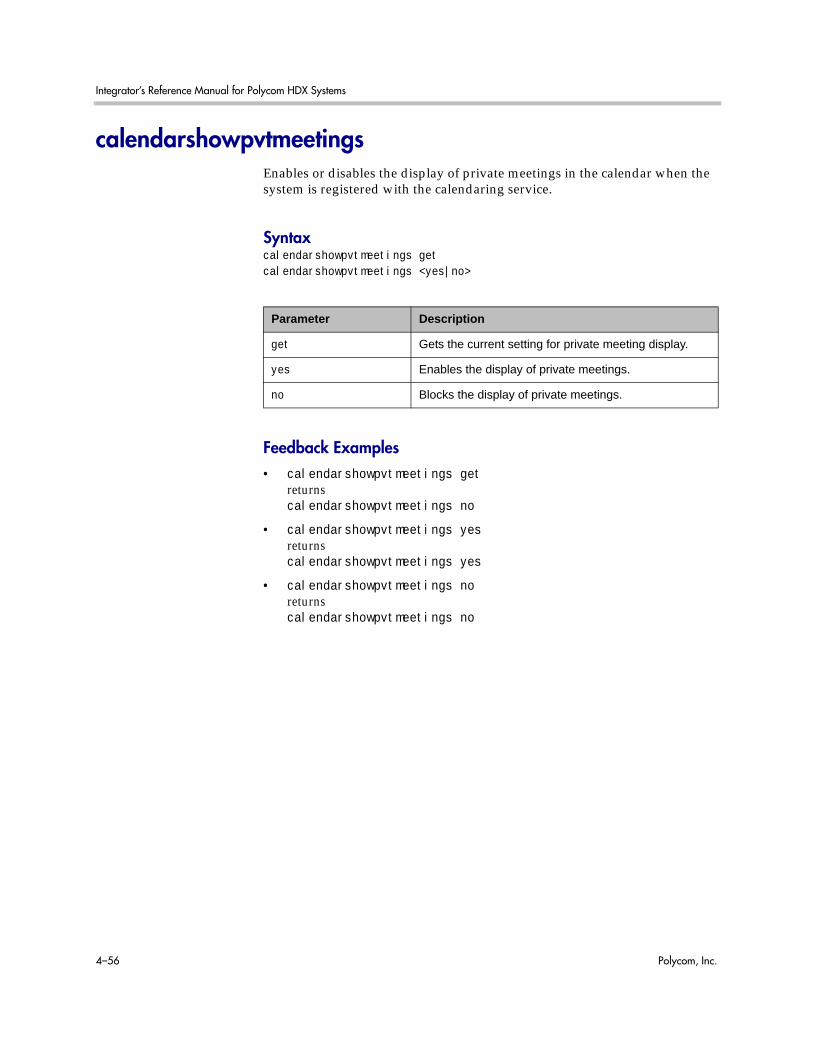
Integrator’s Reference Manual for Polycom HDX Systems
4–56 Polycom, Inc.
calendarshowpvtmeetingsEnables or disables the display of private meetings in the calendar when the system is registered with the calendaring service.
Syntaxcalendarshowpvtmeetings getcalendarshowpvtmeetings <yes|no>
Feedback Examples• calendarshowpvtmeetings get
returnscalendarshowpvtmeetings no
• calendarshowpvtmeetings yesreturnscalendarshowpvtmeetings yes
• calendarshowpvtmeetings noreturnscalendarshowpvtmeetings no
Parameter Description
get Gets the current setting for private meeting display.
yes Enables the display of private meetings.
no Blocks the display of private meetings.

System Commands
Polycom, Inc. 4–57
calendarstatusReturns the status of the Microsoft Exchange server connection.
Syntaxcalendarstatus get
Feedback Examples• calendarstatus get
returnscalendarstatus established
• calendarstatus getreturnscalendarstatus unavailable
See Also Use the calendarregisterwithserver command on page 4-52 to enable or disable the calendaring service.
Parameter Description
get Returns the Microsoft Exchange server connection status.

Integrator’s Reference Manual for Polycom HDX Systems
4–58 Polycom, Inc.
calendaruserGets or sets the user name the calendaring service uses to log in to the Microsoft Exchange server.
Syntaxcalendaruser getcalendaruser “username”
Feedback Examples• calendaruser get
returnscalendaruser jpolycom
See AlsoSee the calendarserver command on page 4-55 to configure the Microsoft Exchange server address used by this service.
Parameter Description
get Returns the user name being used by the calendaring service.
username The user name the calendaring service uses to log in to the Microsoft Exchange server.

System Commands
Polycom, Inc. 4–59
calldetailDisplays all call detail records, a specific call detail record, or the call detail range.
Syntaxcalldetail <“Nth_item”|all>calldetail range
Feedback Examples• calldetail 1
returns1,02/Nov/2008,16:34:34,02/Nov/2008,16:34:34,0:00:00,---,Polycom HDX Demo,192.168.1.101,---,h323,384Kbps,”Polycom/HDX 9004/2.5”,Out,2,1,---,---,---,terminal,192.168.1.101,Siren22,Siren22,H.264,H.264,4SIF,----,"The call has ended.; Local user initiated hangup.",16,---,0.00,0.00,0.00,0.00,0,0,0,0,0,0,0,0
• calldetail rangereturns1..29
Parameter Description
“Nth_item” Displays the Nth call detail record.
all Displays all call detail records.
range Displays the range of records in the call detail report.
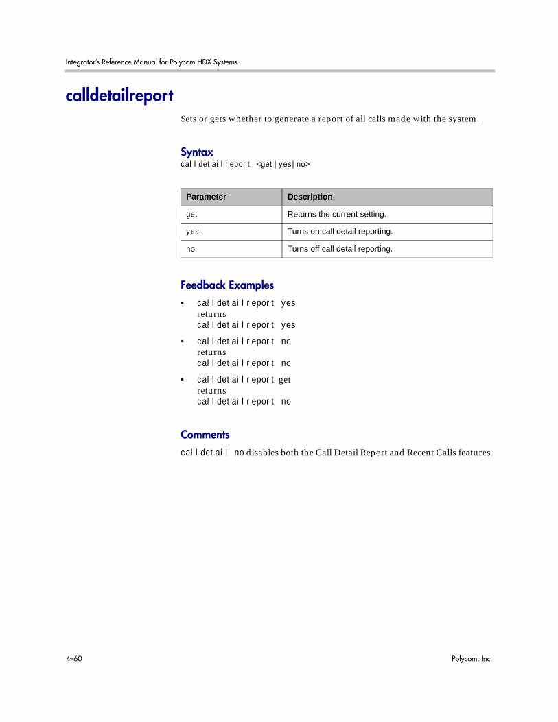
Integrator’s Reference Manual for Polycom HDX Systems
4–60 Polycom, Inc.
calldetailreportSets or gets whether to generate a report of all calls made with the system.
Syntaxcalldetailreport <get|yes|no>
Feedback Examples• calldetailreport yes
returnscalldetailreport yes
• calldetailreport noreturnscalldetailreport no
• calldetailreport getreturnscalldetailreport no
Commentscalldetail no disables both the Call Detail Report and Recent Calls features.
Parameter Description
get Returns the current setting.
yes Turns on call detail reporting.
no Turns off call detail reporting.
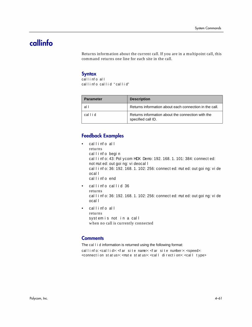
System Commands
Polycom, Inc. 4–61
callinfoReturns information about the current call. If you are in a multipoint call, this command returns one line for each site in the call.
Syntaxcallinfo allcallinfo callid “callid”
Feedback Examples• callinfo all
returnscallinfo begincallinfo:43:Polycom HDX Demo:192.168.1.101:384:connected:notmuted:outgoing:videocallcallinfo:36:192.168.1.102:256:connected:muted:outgoing:videocallcallinfo end
• callinfo callid 36returnscallinfo:36:192.168.1.102:256:connected:muted:outgoing:videocall
• callinfo allreturnssystem is not in a callwhen no call is currently connected
CommentsThe callid information is returned using the following format:
callinfo:<callid>:<far site name>:<far site number>:<speed>:<connection status>:<mute status>:<call direction>:<call type>
Parameter Description
all Returns information about each connection in the call.
callid Returns information about the connection with the specified call ID.

Integrator’s Reference Manual for Polycom HDX Systems
4–62 Polycom, Inc.
callstateSets or gets the call state notification for call state events.
Syntaxcallstate <get|register|unregister>
Feedback Examples• callstate register
returnscallstate registered
• callstate unregisterreturnscallstate unregistered
• callstate getreturnscallstate unregistered
After registering, the following callstate (cs:) data is returned when connecting an IP call:cs: call[34] chan[0] dialstr[192.168.1.103] state[ALLOCATED]cs: call[34] chan[0] dialstr[192.168.1.103] state[RINGING]cs: call[34] chan[0] dialstr[192.168.1.103] state[BONDING]cs: call[34] chan[0] dialstr[192.168.1.103] state[BONDING]cs: call[34] chan[0] dialstr[192.168.1.103] state[COMPLETE]active: call[34] speed [384]
Note: The [BONDING] responses in IP calls are extraneous text that will be removed in a subsequent software version.
After registering, the following response occurs when disconnecting an IP call:cleared: call[34]dialstr[IP:192.168.1.103 NAME:Polycom HDX Demo]ended: call[34]
Parameter Description
get Returns the current setting.
register Registers the system to give notification of call activities.
unregister Disables the register mode.

System Commands
Polycom, Inc. 4–63
See AlsoYou can also use the notify command on page 4-251 and the nonotify command on page 4-250 for notifications.
For more information about call status messages, refer to Status Messages command on page B-1 .

Integrator’s Reference Manual for Polycom HDX Systems
4–64 Polycom, Inc.
callstatsReturns call summary information.
Syntaxcallstats
Feedback Examples• callstats
returnstimeinlastcall 0:02:35totalnumberofcalls 23totalnumberofipcalls 23totaltimeipcalls 2:08:44percentageipcalls 100%totalnumberofisdncalls 0totaltimeisdncalls 00:00:00percentageisdncalls 0%
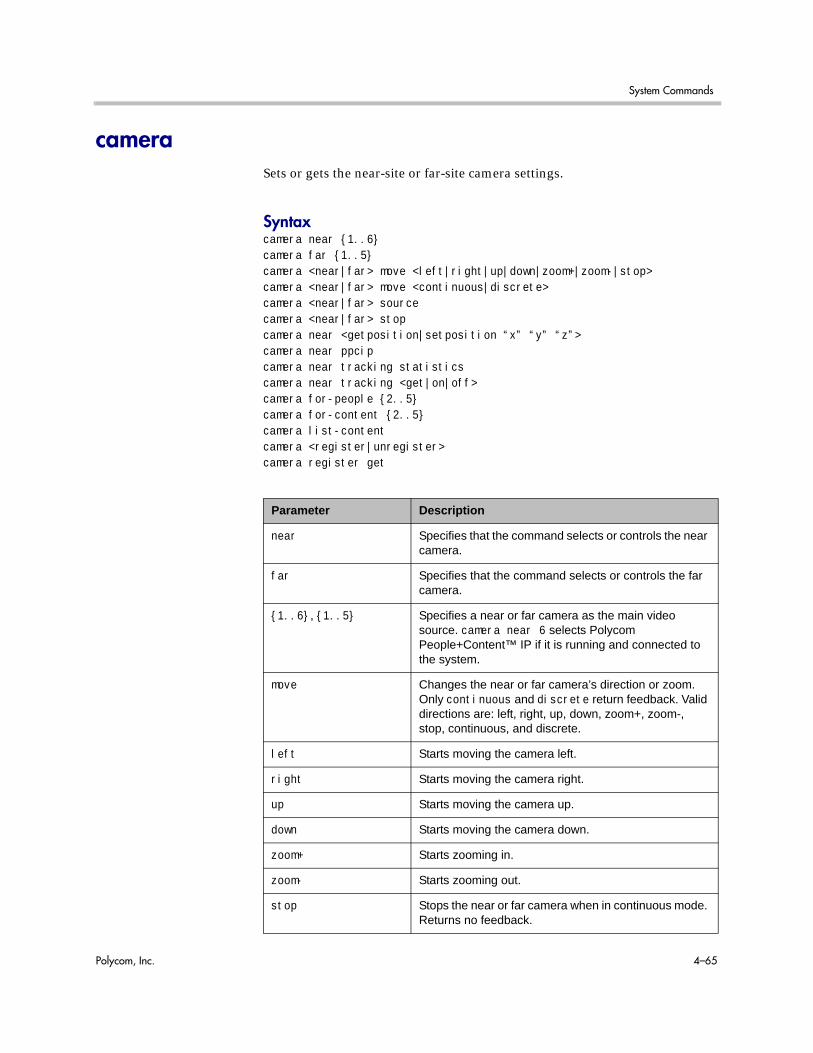
System Commands
Polycom, Inc. 4–65
cameraSets or gets the near-site or far-site camera settings.
Syntaxcamera near {1..6}camera far {1..5}camera <near|far> move <left|right|up|down|zoom+|zoom-|stop> camera <near|far> move <continuous|discrete> camera <near|far> sourcecamera <near|far> stopcamera near <getposition|setposition “x” “y” “z”> camera near ppcipcamera near tracking statisticscamera near tracking <get|on|off>camera for-people {2..5}camera for-content {2..5}camera list-contentcamera <register|unregister>camera register get
Parameter Description
near Specifies that the command selects or controls the near camera.
far Specifies that the command selects or controls the far camera.
{1..6}, {1..5} Specifies a near or far camera as the main video source. camera near 6 selects Polycom People+Content™ IP if it is running and connected to the system.
move Changes the near or far camera’s direction or zoom. Only continuous and discrete return feedback. Valid directions are: left, right, up, down, zoom+, zoom-, stop, continuous, and discrete.
left Starts moving the camera left.
right Starts moving the camera right.
up Starts moving the camera up.
down Starts moving the camera down.
zoom+ Starts zooming in.
zoom- Starts zooming out.
stop Stops the near or far camera when in continuous mode. Returns no feedback.

Integrator’s Reference Manual for Polycom HDX Systems
4–66 Polycom, Inc.
continuous Selects continuous movement mode. The camera moves in direction specified until a camera <near|far> move stop command is sent. This is the default setting.
discrete Selects discrete movement mode. The camera moves a small amount in the direction specified and then stop. No stop command is required.
source Returns the number of the near or far camera source currently selected.
getposition Gets the pan, tilt, and zoom coordinates of the currently selected PTZ camera in the format of pan tilt zoom.
setposition “x” “y” “z”
Sets the pan (x), tilt (y), and zoom (z) coordinates of the currently selected PTZ camera. Camera PTZ range:
-880 <= pan <= 880
-300 <= tilt <= 300
0 <= zoom <= 1023
Notes:
The camera PTZ range applies to the Polycom EagleEye HD camera. Different cameras might have different PTZ values.
Some D30 cameras might not be able to reach the designed range limit. For example, although the pan limit is 880, the camera might only be able to reach 860.
ppcip Specifies People+Content IP as the main video source if it is running and connected to the system.
for-people {2..5} Sets the source for the specified camera to People.
for-content {2..5} Sets the source for the specified camera to Content.
list-content Gets a list of cameras configured as Content.
register Registers to receive feedback when the user changes the camera source. Returns the current camera registration state when followed by the get parameter.
Parameter Description

System Commands
Polycom, Inc. 4–67
Feedback Examples• camera far 2
specifies camera 2 at the far-site and returnscamera far 2
• camera far move leftcauses the far-site camera to start panning to the left and returnsevent: camera far move left
• camera near move zoom+causes the near-site camera to zoom in and returnsevent: camera near move zoom+
• camera registerreturnscamera registered
• camera unregisterreturnscamera unregistered
• camera near tracking statisticsreturnsEagleEye Director Tracking Statistics beginTracking Disable Percentage: 3%View Switching Frequency (Per Hour): 50EagleEye Director Tracking Statistics end
• camera near tracking offreturnscamera near tracking off
unregister Unregisters to receive feedback when the user changes the camera source.
tracking statistics Gets EagleEye Director tracking statistics. Tracking statistics measure:
• the amount of time tracking is turned off divided by the total call time in the most recent 100 calls lasting more than five minutes.
• the amount of room and close-up view switches divided by the total call time in the most recent 100 calls lasting more than five minutes.
tracking <get|on|off>
Enables or disables the Polycom EagleEye Director tracking feature. on turns the tracking feature on, off turns the tracking feature off, and get returns the current tracking feature setting.
Parameter Description

Integrator’s Reference Manual for Polycom HDX Systems
4–68 Polycom, Inc.
• camera near tracking on returnscamera near tracking on
• camera near tracking get returnscamera near tracking Voice
CommentsIf the camera near {1..6} API command is used for an input configured as content, the command becomes a toggle. You must send the command once to send the content source and a second time to stop the content source.The camera near 6 command and the camera near ppcip command provide the same functionality.
The camera register command does not return local camera movements if the camera is moved using the remote control or the web interface.
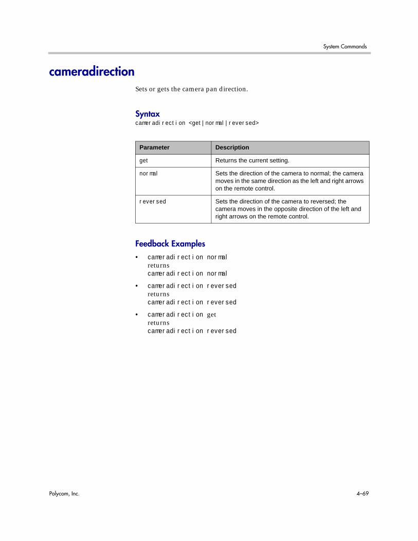
System Commands
Polycom, Inc. 4–69
cameradirectionSets or gets the camera pan direction.
Syntaxcameradirection <get|normal|reversed>
Feedback Examples• cameradirection normal
returnscameradirection normal
• cameradirection reversedreturnscameradirection reversed
• cameradirection getreturnscameradirection reversed
Parameter Description
get Returns the current setting.
normal Sets the direction of the camera to normal; the camera moves in the same direction as the left and right arrows on the remote control.
reversed Sets the direction of the camera to reversed; the camera moves in the opposite direction of the left and right arrows on the remote control.

Integrator’s Reference Manual for Polycom HDX Systems
4–70 Polycom, Inc.
camerainputSets or gets the format for a video source.
Syntaxcamerainput <1|2|3> <get|s-video|composite|component>camerainput <4|5> <get|dvi|vga>
Feedback Examples• camerainput 1 composite
returnscamerainput 1 component
• camerainput 2 s-videoreturnscamerainput 2 s-video
• camerainput 2 getreturnscamerainput 2 s-video
• camerainput 3 dvireturnscamerainput 3 dvi
• camerainput 4 vgareturnscamerainput 4 vga
Parameter Description
<1..5> Specifies the video source. camerainput 5 is available only on the Polycom HDX 9004.
get Returns the current setting.
s-video Specifies that the video source is connected using S-Video.
composite Specifies that the video source is connected using a composite connector.
component Specifies that the video source is connected using a component connector.
dvi Specifies that the video source is connected using DVI.
vga Specifies that the video source is connected using VGA.

System Commands
Polycom, Inc. 4–71
chaircontrolSends various chair control commands while the system is in a multipoint call.
Syntaxchaircontrol end_confchaircontrol hangup_term “term_no”chaircontrol listchaircontrol rel_chairchaircontrol <register|unregister>chaircontrol req_chairchaircontrol req_floorchaircontrol req_term_name “term_no”chaircontrol req_vaschaircontrol set_broadcaster “term_no”chaircontrol set_term_name “term_no” “term_name”chaircontrol stop_viewchaircontrol view “term_no”chaircontrol view_broadcaster
Parameter Description
end_conf Ends the call and returns the same feedback as hangup_term for each site in the call.
hangup_term “term_no”
Disconnects the specified site from the call.
list Lists the sites in the call.
rel_chair Releases the chair.
register Registers to receive feedback on all chair control operations.
unregister Unregisters (stops feedback on all chair control operations).
req_chair Requests the chair.
req_floor Requests the floor.
req_term_name “term_no”
Requests the name for the specified terminal number.
req_vas Requests voice-activated switching.
set_broadcaster “term_no”
Requests the specified terminal to become the broadcaster.
set_term_name “term_no” “term_name”
Sets the name for the specified terminal number.

Integrator’s Reference Manual for Polycom HDX Systems
4–72 Polycom, Inc.
Feedback Examples• chaircontrol rel_chair
returnschaircontrol rel_chair grantedchaircontrol view 1.1 granted
• chaircontrol req_vasreturnschaircontrol req_vas grantedchaircontrol view 1.1 granted
• chaircontrol hangup_term 1.4returnschaircontrol del_term 1.4chaircontrol terminal 1.4 left conferencecleared: call[34]dialstring[IP:192.168.1.101 NAME:Polycom HDX Demo]ended: call[34]
CommentsTerminal numbers are set by the MCU and are of the form x.y where x is the MCU and y is the participant.
You only need to enclose a parameter in quotes if it contains a space.
stop_view Stops viewing the specified terminal.
view “term_no” Views the specified terminal.
view_broadcaster Views the broadcaster.
Parameter Description

System Commands
Polycom, Inc. 4–73
clientvalidatepeercertEnables certificate validation by specifying whether the HDX system requires the server to present a valid certificate when the server makes secure connections for services such as provisioning, directory search, and session initiation protocol (SIP) calling.
Syntaxclientvalidatepeercert getclientvalidatepeercert <yes|no>
Feedback Examples• clientvalidatepeercert get
returnsclientvalidatepeercert no
• clientvalidatepeercert yesreturnsclientvalidatepeercert yes
Parameter Description
get Returns the peer certificate validation setting for client.
yes Enables the peer certificate validation requirement for client.
no Disables the peer certificate validation requirement for client.

Integrator’s Reference Manual for Polycom HDX Systems
4–74 Polycom, Inc.
cmdechoTurns command echoing on or off.
Syntaxcmdecho <on|off>
Feedback Examples• cmdecho on
returnscmdecho on
• cmdecho offreturnscmdecho off
CommentsThis setting defaults to on every time the system powers up. You might want to turn off command echoing when sending batches of commands (in an init script) to simplify the output.
Parameter Description
on Turns on command echoing so that everything you type is echoed on the screen.
off Turns off command echoing so that nothing you type is echoed on the screen.

System Commands
Polycom, Inc. 4–75
colorbarTurns the video diagnostics color bars on or off.
Syntaxcolorbar <on|off>
Feedback Examples• colorbar on
returnscolorbar on
• colorbar offreturnscolorbar off
Parameter Description
on Turns on the color bar test pattern.
off Turns off the color bar test pattern.

Integrator’s Reference Manual for Polycom HDX Systems
4–76 Polycom, Inc.
configchange (deprecated)Sets or gets the notification state for configuration changes. This command has been deprecated.
Syntaxconfigchange <get|register|unregister>
Feedback Examples• configchange register
returnsconfigchange registered
• configchange unregisterreturnsconfigchange unregistered
• configchange getreturnsconfigchange unregistered
Parameter Description
get Returns the current setting.
register Registers to receive notifications when configuration variables have changed.
unregister Unregisters to receive notifications when configuration variables have changed.

System Commands
Polycom, Inc. 4–77
configdisplaySets or gets the video format, aspect ratio and resolution for Monitor 1 or Monitor 2.
Syntaxconfigdisplay [<monitor1|monitor2>] getconfigdisplay <monitor1|monitor2> <component|vga|dvi|composite|s_video> <4:3|16:9>configdisplay <monitor1|monitor2> <component|vga|dvi|composite|s_video> <4:3|16:9> [<720p|1080i|1080p>] [<50hz720p|60hz720p|50hz1080i|60hz1080i|50hz1080p|60hz1080p>]configdisplay monitor2 off
Parameter Description
get Returns the current setting.
monitor1 Specifies Monitor 1.
monitor2 Specifies Monitor 2.
s_video Sets the specified display to S-Video format.
composite Sets the specified display to Composite format.
vga Sets the specified display to VGA format.
dvi Sets the specified display to DVI format.
component Sets the specified display to Component format.
4:3 Sets the display aspect ratio to 4:3 (standard).
16:9 Sets the display aspect ratio to 16:9 (wide screen).
720p Sets the resolution to 1280x720p, 50-60 Hz (refresh rate determined by whether unit is PAL or NTSC, respectively). For monitors with Component format and 16:9 aspect ratio only.
1080i Sets the resolution to 1920x1080i, 50-60 Hz (refresh rate determined by whether unit is PAL or NTSC, respectively). For monitors with Component format and 16:9 aspect ratio only.
1080p Sets the resolution to 1920x1080p, 50-60 Hz (refresh rate determined by whether unit is PAL or NTSC, respectively). For monitors with Component format and 16:9 aspect ratio only.
50hz720p Sets the resolution to 1280x720p, 50 Hz (PAL systems-only). For monitors with Component format and 16:9 aspect ratio only.
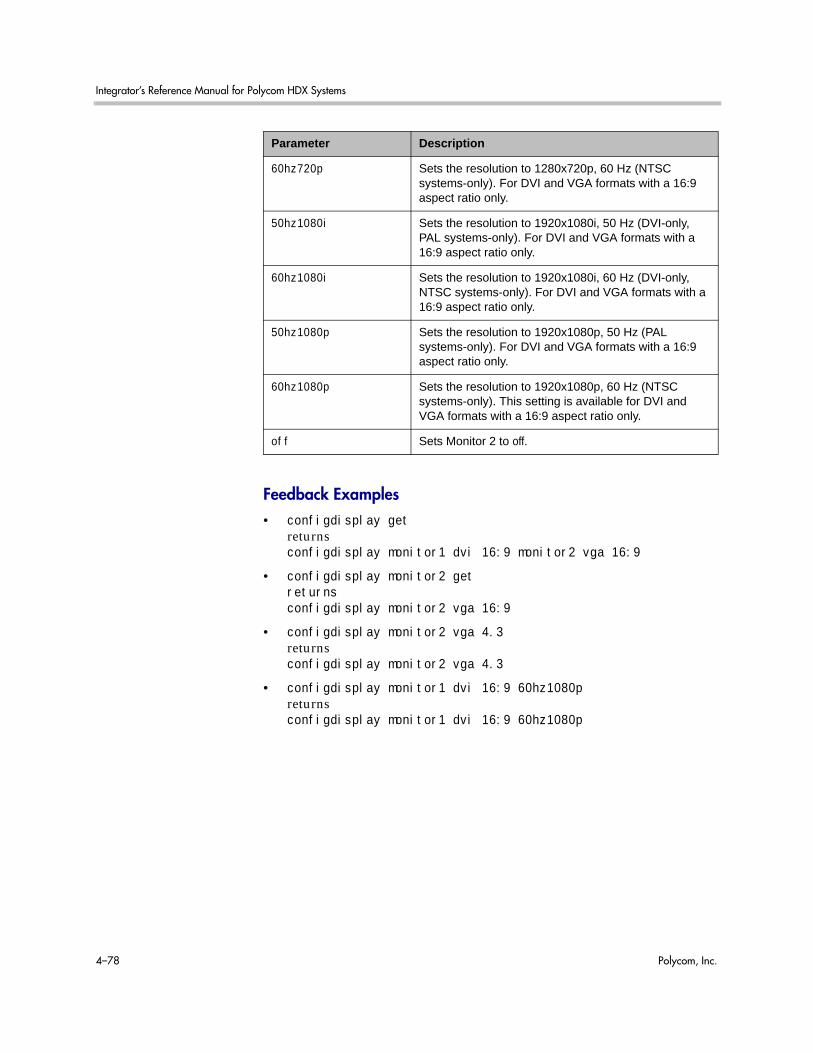
Integrator’s Reference Manual for Polycom HDX Systems
4–78 Polycom, Inc.
Feedback Examples• configdisplay get
returnsconfigdisplay monitor1 dvi 16:9 monitor2 vga 16:9
• configdisplay monitor2 getreturnsconfigdisplay monitor2 vga 16:9
• configdisplay monitor2 vga 4.3returnsconfigdisplay monitor2 vga 4.3
• configdisplay monitor1 dvi 16:9 60hz1080preturnsconfigdisplay monitor1 dvi 16:9 60hz1080p
60hz720p Sets the resolution to 1280x720p, 60 Hz (NTSC systems-only). For DVI and VGA formats with a 16:9 aspect ratio only.
50hz1080i Sets the resolution to 1920x1080i, 50 Hz (DVI-only, PAL systems-only). For DVI and VGA formats with a 16:9 aspect ratio only.
60hz1080i Sets the resolution to 1920x1080i, 60 Hz (DVI-only, NTSC systems-only). For DVI and VGA formats with a 16:9 aspect ratio only.
50hz1080p Sets the resolution to 1920x1080p, 50 Hz (PAL systems-only). For DVI and VGA formats with a 16:9 aspect ratio only.
60hz1080p Sets the resolution to 1920x1080p, 60 Hz (NTSC systems-only). This setting is available for DVI and VGA formats with a 16:9 aspect ratio only.
off Sets Monitor 2 to off.
Parameter Description

System Commands
Polycom, Inc. 4–79
configparamSets or gets the video quality setting for the specified video input for motion or sharpness.
Syntaxconfigparam <“parameter”> getconfigparam <“parameter”> set <“value”>
Feedback Examples• configparam camera_video_quality 1 set motion
returnscamera1_video_quality motion
Parameter Possible Values Description
camera_video_quality <1|2|3|4>
motion|sharpness Sets or gets the video quality setting for the specified video input for motion or for sharpness (for images without motion).

Integrator’s Reference Manual for Polycom HDX Systems
4–80 Polycom, Inc.
configpresentationSets or gets the content presentation settings for Monitor 1 or Monitor 2.
Syntaxconfigpresentation getconfigpresentation <monitor1|monitor2> getconfigpresentation monitor1 <near|far|content|near-or-far|content-or-near|content-or-far|all|none>configpresentation monitor2 <near|far|content|near-or-far|content-or-near|content-or-far|all|none>configpresentation monitor1 "value" monitor2 "value"
Parameter Description
get Returns the current settings for the active monitors.
monitor1 Specifies settings for Monitor 1.
monitor2 Specifies settings for Monitor 2.
near Selects near-site video as the video source to display on the specified monitor.
far Selects far-site video as the video source to display on the specified monitor.
content Selects content as the video source to display on the specified monitor.
near-or-far Selects both near-site and far-site video as video sources to display on the specified monitor.
content-or-near Selects both near-site video and content as video sources to display on the specified monitor.
content-or-far Selects both content and far-site video as video sources to display on the specified monitor.
all Selects content, near-site video, and far-site video as video sources for the specified monitor.
none Clears all video sources for the specified monitor.
“value” Sets presentation mode for both monitors.

System Commands
Polycom, Inc. 4–81
Feedback Examples• configpresentation monitor1 get
returnsconfigpresentation monitor1:all
• configpresentation monitor2 getreturnsconfigpresentation monitor2:near-or-far
• configpresentation monitor2 farreturnserror: configpresentation not applied since monitor2 is offwhen monitor 2 is off

Integrator’s Reference Manual for Polycom HDX Systems
4–82 Polycom, Inc.
confirmdiraddSets or gets the configuration for prompting users to add directory entries for the far sites when a call disconnects.
Syntaxconfirmdiradd <get|yes|no>
Feedback Examples• confirmdiradd no
returnsconfirmdiradd no
• confirmdiradd yesreturnsconfirmdiradd yes
• confirmdiradd getreturnsconfirmdiradd yes
Parameter Description
get Returns the current setting.
yes When a call disconnects, the user is prompted to create a local directory entry for the far site if it is not already in the directory.
no The user is not prompted to create a local directory entry after a call disconnects.

System Commands
Polycom, Inc. 4–83
confirmdirdelSets or gets the configuration for requiring users to confirm directory deletions.
Syntaxconfirmdirdel <get|yes|no>
Feedback Examples• confirmdirdel no
returnsconfirmdirdel no
• confirmdirdel yesreturnsconfirmdirdel yes
• confirmdirdel getreturnsconfirmdirdel yes
Parameter Description
get Returns the current setting.
yes When deleting an entry from the directory (address book), the user is prompted with “Are you sure you want to delete this entry?”
no When deleting an entry from the directory (address book), the user is not prompted with a message.

Integrator’s Reference Manual for Polycom HDX Systems
4–84 Polycom, Inc.
contentautoSets or gets the automatic bandwidth adjustment for people and content in point-to-point H.323 calls. Automatic adjustment maintains equal image quality in the two streams.
Syntaxcontentauto <get|on|off>
Feedback Examples• contentauto off
returnscontentauto off
• contentauto onreturnscontentauto on
• contentauto getreturnscontentauto on
Parameter Description
get Returns the current setting.
on Enables automatic bandwidth adjustment for people and content.
off Disables automatic bandwidth adjustment for people and content. The system Quality Preference settings is used instead.
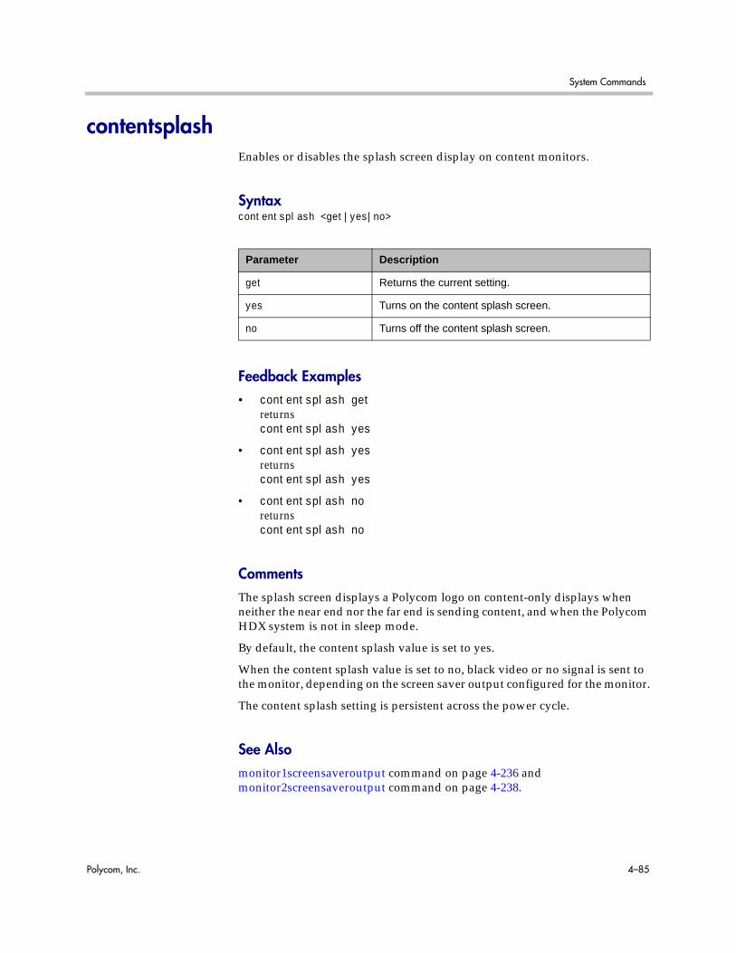
System Commands
Polycom, Inc. 4–85
contentsplashEnables or disables the splash screen display on content monitors.
Syntaxcontentsplash <get|yes|no>
Feedback Examples• contentsplash get
returnscontentsplash yes
• contentsplash yesreturnscontentsplash yes
• contentsplash noreturnscontentsplash no
CommentsThe splash screen displays a Polycom logo on content-only displays when neither the near end nor the far end is sending content, and when the Polycom HDX system is not in sleep mode.
By default, the content splash value is set to yes.
When the content splash value is set to no, black video or no signal is sent to the monitor, depending on the screen saver output configured for the monitor.
The content splash setting is persistent across the power cycle.
See Alsomonitor1screensaveroutput command on page 4-236 and monitor2screensaveroutput command on page 4-238.
Parameter Description
get Returns the current setting.
yes Turns on the content splash screen.
no Turns off the content splash screen.

Integrator’s Reference Manual for Polycom HDX Systems
4–86 Polycom, Inc.
contentvideoadjustmentSets or gets the content video adjustment setting.
Syntaxcontentvideoadjustment <get|normal|stretch|zoom>
Feedback Examples• contentvideoadjustment zoom
returnscontentvideoadjustment zoom
• contentvideoadjustment stretchreturnscontentvideoadjustment stretch
• contentvideoadjustment normalreturnscontentvideoadjustment normal
• contentvideoadjustment getreturnscontentvideoadjustment normal
Parameter Description
get Returns the current setting.
normal Preserves the aspect ratio of the source video. The image is scaled (if necessary) to the largest supported resolution that fits on the display without cropping.
stretch Does not preserve aspect ratio. The image is scaled horizontally and vertically to exactly match the resolution of the display.
zoom Preserves the aspect ratio of the source video. The image is scaled to exactly match one of the display dimensions while matching or exceeding the other display dimension. The image is centered and cropped.
System Commands
Polycom, Inc. 4–87
countryGets the country setting for the system.
Syntaxcountry get
Feedback Examples• country get
returnscountry “united states”
Parameter Description
get Returns the current setting.

Integrator’s Reference Manual for Polycom HDX Systems
4–88 Polycom, Inc.
ctsSets or gets the CTS serial interface control signal (clear to send) configuration. This command is only applicable if you have a V.35 network interface connected to your system.
Syntaxcts <get|normal|inverted|ignore>
Feedback Examples• cts normal
returnscts normal
• cts invertedreturnscts inverted
• cts getreturnscts inverted
CommentsThe default setting for this signal is “normal”.
Parameter Description
get Returns the current setting.
normal Sets the signal to normal (high voltage is logic 1).
inverted Sets the signal to inverted (low voltage is logic 1).
ignore Ignores the signal.

System Commands
Polycom, Inc. 4–89
daylightsavingsSets or gets the daylight savings time setting. When you enable this setting, the system clock automatically changes for daylight saving time.
Syntaxdaylightsavings <get|yes|no>
Feedback Examples• daylightsavings no
returnsdaylightsavings no
• daylightsavings yesreturnsdaylightsavings yes
• daylightsavings getreturnsdaylightsavings yes
Parameter Description
get Returns the current setting.
yes Enables automatic adjustment for daylight savings time.
no Disables automatic adjustment for daylight savings time.

Integrator’s Reference Manual for Polycom HDX Systems
4–90 Polycom, Inc.
dcdSets the configuration for the DCD serial interface control signal (data carrier detect). This command is only applicable if you have a V.35 network interface connected to your system.
Syntaxdcd <normal|inverted>
Feedback Examples• dcd normal
returnsdcd normal
• dcd invertedreturnsdcd inverted
CommentsThe default setting for this signal is “normal”.
Parameter Description
normal Sets the signal to normal (high voltage is logic 1).
inverted Sets the signal to inverted (low voltage is logic 1).
System Commands
Polycom, Inc. 4–91
dcdfilterSets or gets the filter setting of the DCD serial interface control signal (data carrier detect). This command is only applicable if you have a V.35 network interface connected to your system.
Syntaxdcdfilter <get|on|off>
Feedback Examples• dcdfilter on
returnsdcdfilter on
• dcdfilter offreturnsdcdfilter off
• dcdfilter getreturnsdcdfilter off
CommentsWhen this filter is enabled, DCD drops for 60 seconds before changing the call state. The default setting for this signal is “off”.
Parameter Description
get Returns the current setting.
on Enables the DCD filter.
off Disables the DCD filter.

Integrator’s Reference Manual for Polycom HDX Systems
4–92 Polycom, Inc.
defaultgatewaySets or gets the default gateway.
Syntaxdefaultgateway getdefaultgateway set “xxx.xxx.xxx.xxx”
Feedback Examples• defaultgateway set 192.168.1.101
returnsdefaultgateway 192.168.1.101
CommentsThis setting can only be changed if DHCP is turned off. After making a change, you must restart the system for the setting to take effect.
Parameter Description
get Returns the default gateway IP address.
set Sets the default gateway when followed by the “xxx.xxx.xxx.xxx” parameter.
“xxx.xxx.xxx.xxx” IP address to use as the default gateway.
System Commands
Polycom, Inc. 4–93
destunreachabletxSets or gets the system’s ability to generate a Destination Unreachable ICMP message in response to a packet that cannot be delivered to its destination for reasons other than congestion.
Syntaxdestunreachabletx <yes|no>
Feedback Examples• destunreachabletx
returnsdestunreachabletx no
• destunreachabletx yesreturnsdestunreachabletx yes
CommentsThis setting is applicable for both IPv4 and IPv6 configurations. After making a change, you must restart the system for the setting to take effect.
See Alsoicmpoutpacketrate on page 4-185.
Parameter Description
get Returns the current setting.
yes Enables the system’s ability to generate a destination unreachable ICMP message in response to a packet that cannot be delivered to its destination for reasons other than congestion.
no Disables the system’s ability to generate a destination unreachable ICMP message in response to a packet that cannot be delivered to its destination for reasons other than congestion.
Integrator’s Reference Manual for Polycom HDX Systems
4–94 Polycom, Inc.
dhcpSets or gets DHCP options.
Syntaxdhcp <get|off|client>
Feedback Examples• dhcp off
returnsdhcp off
• dhcp clientreturnsdhcp client
• dhcp getreturnsdhcp client
CommentsAfter making a change, you must restart the system for the setting to take effect.
Parameter Description
get Returns the selected DHCP option.
off Disables DHCP.
client Enables DHCP client, setting the system to obtain an IP address from a server on your network.

System Commands
Polycom, Inc. 4–95
dialDials video or audio calls either manually or from the directory.
Syntaxdial addressbook “addr book name”dial auto “speed” “dialstr”dial manual <56|64> “dialstr1” “dialstr2” [h320]dial manual “speed” “dialstr1” [“dialstr2”] [h323|h320|ip|isdn|sip]dial phone “dialstring”dial phone <pots|isdn_phone|sip_speakerphone> "dialstring"
Parameter Description
addressbook Dials a directory (address book) entry. Requires the name of the entry.
“addr book name” The name of the directory (address book) entry. The name may be up to 25 characters. Use quotation marks around strings that contain spaces. For example: “John Doe”.
auto Dials a video call number dialstr1 at speed of type h323 or h320. Requires the parameters “speed” and “dialstr”. Allows the user to automatically dial a number. The system first attempts H.323 and if that fails, rolls over to H.320. Deprecated. Instead of this command, Polycom recommends using dial manual and not specifying a call type.
“speed” Valid data rate for the network.
“dialstr”, “dialstr1”, “dialstr2”
Valid ISDN or IP directory number.
manual Dials a video call number dialstr1 at speed of type h323 or h320. Requires the parameters “speed” and “dialstr1”.
Use dial manual “speed” “dialstr” “type” when you do not want automatic call rollover or when the dialstring might not convey the intended transport (for example, an extension with an IP gateway might look like an ISDN number, but in fact corresponds to an IP address).
56|64 Specifies speed for two-channel calls.
h323|h320|ip|isdn|sip Type of call.
Note: The parameters ip and isdn are deprecated.
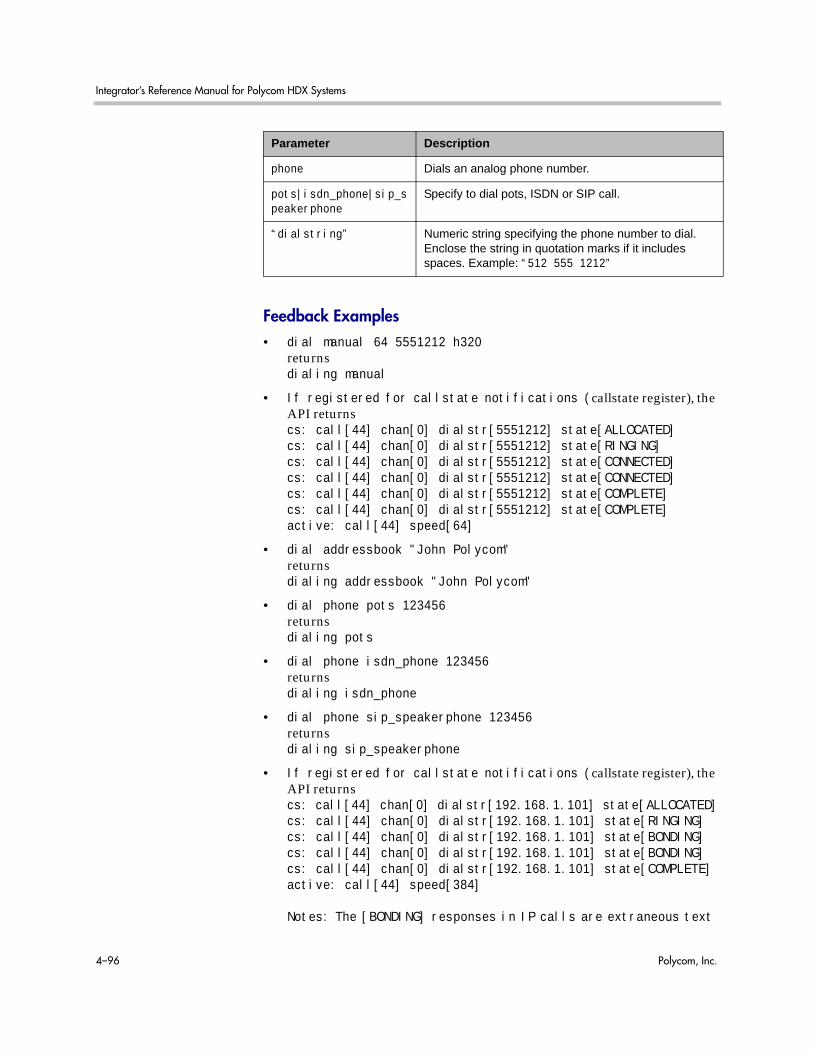
Integrator’s Reference Manual for Polycom HDX Systems
4–96 Polycom, Inc.
Feedback Examples• dial manual 64 5551212 h320
returnsdialing manual
• If registered for callstate notifications (callstate register), the API returnscs: call[44] chan[0] dialstr[5551212] state[ALLOCATED]cs: call[44] chan[0] dialstr[5551212] state[RINGING]cs: call[44] chan[0] dialstr[5551212] state[CONNECTED]cs: call[44] chan[0] dialstr[5551212] state[CONNECTED]cs: call[44] chan[0] dialstr[5551212] state[COMPLETE]cs: call[44] chan[0] dialstr[5551212] state[COMPLETE]active: call[44] speed[64]
• dial addressbook "John Polycom"returnsdialing addressbook "John Polycom"
• dial phone pots 123456returnsdialing pots
• dial phone isdn_phone 123456returnsdialing isdn_phone
• dial phone sip_speakerphone 123456returnsdialing sip_speakerphone
• If registered for callstate notifications (callstate register), the API returnscs: call[44] chan[0] dialstr[192.168.1.101] state[ALLOCATED]cs: call[44] chan[0] dialstr[192.168.1.101] state[RINGING]cs: call[44] chan[0] dialstr[192.168.1.101] state[BONDING]cs: call[44] chan[0] dialstr[192.168.1.101] state[BONDING]cs: call[44] chan[0] dialstr[192.168.1.101] state[COMPLETE]active: call[44] speed[384]
Notes: The [BONDING] responses in IP calls are extraneous text
phone Dials an analog phone number.
pots|isdn_phone|sip_speakerphone
Specify to dial pots, ISDN or SIP call.
“dialstring” Numeric string specifying the phone number to dial. Enclose the string in quotation marks if it includes spaces. Example: “512 555 1212”
Parameter Description

System Commands
Polycom, Inc. 4–97
that will be removed in a subsequent software version.
Call ID (call [44]) is an example of the response. The Call ID number depends upon the call type.
• If registered for callstatus notifications (notify callstatus), the API returns,notification:callstatus:outgoing:45:null 1::opened::0:videocallnotification:callstatus:outgoing:45: Polycom Austin: 192.168.1.101:connecting:384:0:videocallnotification:callstatus:outgoing:45: Polycom Austin: 192.168.1.101:connected:384:0:videocall
Note: The call ID number (45) is an example of the response. The Call ID number depends upon the call type.
CommentsWhen searching for feedback from the dial command, expect to see the set of described strings as many times as there are channels in the call.
When initiating a multipoint call or adding multiple sites to a multipoint call over ISDN, you must be sure that the total call rate does not exceed the bandwidth of the ISDN interface. Otherwise, one of the calls may not connect.
For example, the total ISDN bandwidth for a T1 line is 1544 kbit/s. Thus, making the following five calls in succession violates the ISDN bandwidth rule, because the total ISDN bandwidth would require 1920 kbit/s (1920 = 384 * 5), and one of the calls may not connect:
• dial manual 384 5551212dial manual 384 5561212dial manual 384 5571212dial manual 384 5581212dial manual 384 5591212
Similarly, making the following two calls in a multipoint call where sites 1, 2, and 3 are already connected at 256 kbits/s each violates the ISDN bandwidth rule. This is because the total ISDN bandwidth required becomes 1792 kbits/s (1792 = 256 * 3 + 512 * 2), and one of these two new calls may not connect:
• dial manual 512 5581212dial manual 512 5591212
Note: The ISDN bandwidth rule is not applicable to IP calls and only applies when multiple ISDN dial commands are issued in succession without waiting for the active call notification (i.e., active: call[36] speed[128]) between dial commands. Adding single calls to a multipoint call and then waiting for the active call notification does not break the rule, because the system downspeeds calls to meet the required ISDN bandwidth limitations.

Integrator’s Reference Manual for Polycom HDX Systems
4–98 Polycom, Inc.
See AlsoRefer to the callstate command on page 4-62. You can use callstate register to obtain updated information on the status of a call. For example, when using the dial manual to place a call, callstate register can tell you when the call is connected.
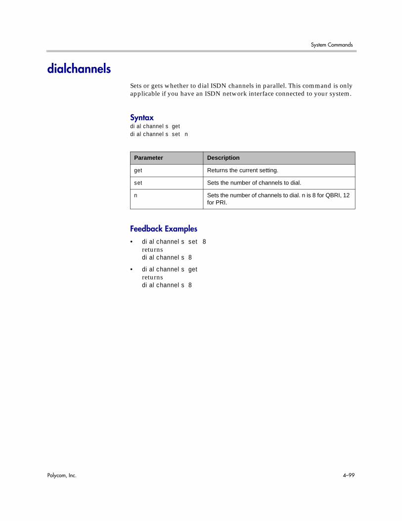
System Commands
Polycom, Inc. 4–99
dialchannelsSets or gets whether to dial ISDN channels in parallel. This command is only applicable if you have an ISDN network interface connected to your system.
Syntaxdialchannels getdialchannels set n
Feedback Examples• dialchannels set 8
returnsdialchannels 8
• dialchannels getreturnsdialchannels 8
Parameter Description
get Returns the current setting.
set Sets the number of channels to dial.
n Sets the number of channels to dial. n is 8 for QBRI, 12 for PRI.

Integrator’s Reference Manual for Polycom HDX Systems
4–100 Polycom, Inc.
diffservaudio, diffservfecc, diffservvideoSets or gets the DiffServ option and specifies a priority level for audio, far-end camera control (FECC) and other call control channels, and video, respectively. The priority level value for each can be between 0 and 63.
Syntaxdiffservaudio getdiffservaudio set {0..63}diffservfecc getdiffservfecc set {0..63}diffservvideo getdiffservvideo set {0..63}
Feedback Examples• diffservaudio set 2
returnsdiffservaudio 2
• diffservaudio getreturnsdiffservaudio 2
CommentsThe diffservfecc command is equivalent to the Control setting in the user interface.
If the typeofservice command on page 4-331 is set to ip-precedence rather than to diffserv, these commands are not applicable.
Parameter Description
get Returns the current setting.
set Sets the command. A priority level in the range {0..63} is required.
{0..63} Specifies the priority level.
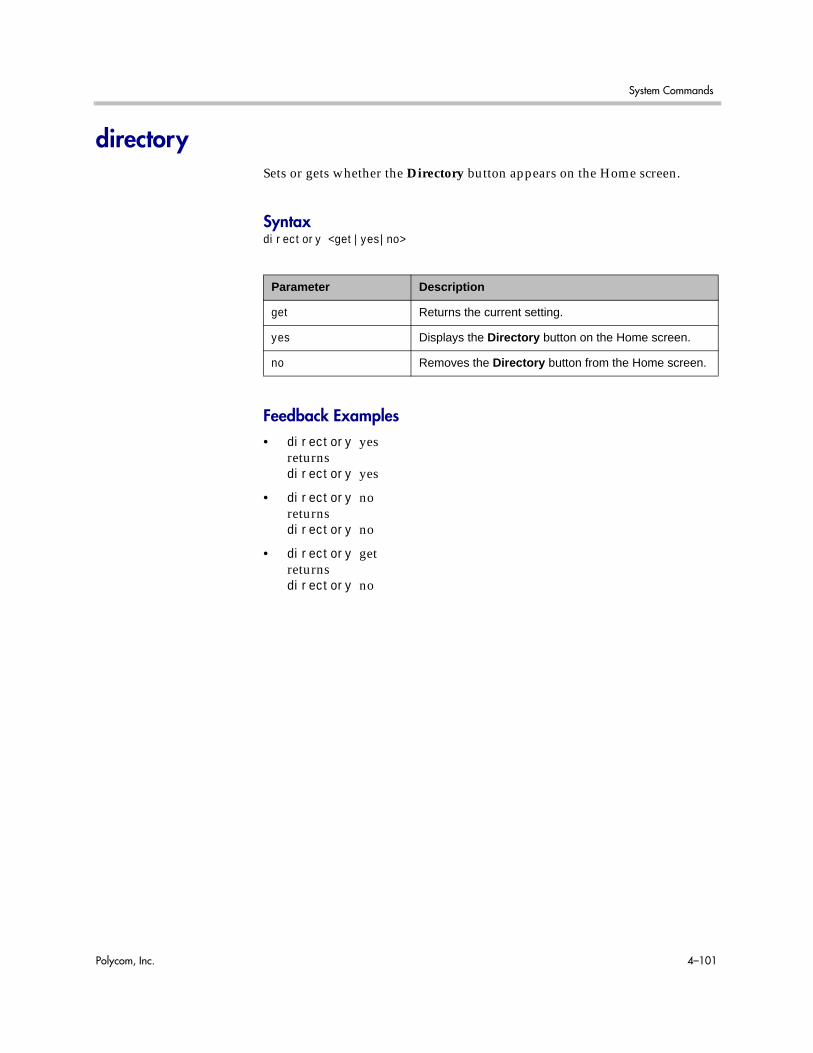
System Commands
Polycom, Inc. 4–101
directorySets or gets whether the Directory button appears on the Home screen.
Syntaxdirectory <get|yes|no>
Feedback Examples• directory yes
returnsdirectory yes
• directory noreturnsdirectory no
• directory getreturnsdirectory no
Parameter Description
get Returns the current setting.
yes Displays the Directory button on the Home screen.
no Removes the Directory button from the Home screen.

Integrator’s Reference Manual for Polycom HDX Systems
4–102 Polycom, Inc.
display (deprecated)Displays information about the current call or the system. With the implementation of the callinfo command on page 4-61 and whoami command on page 4-367, this command has been deprecated.
Syntaxdisplay calldisplay whoami
Feedback Examples• display call
returnsCall ID Status SpeedDialed Num----------------------------------------34CM_CALLINFO_CONNECTED 384192.168.1.101
• display whoamireturnsHi, my name is: Polycom HDX DemoHere is what I know about myself:Model: HDX9004Serial Number: 82065205E72EC1Software Version: Release 2.5 - 30Nov2008 11:30Build Information: root on domain.polycom.comFPGA Revision: 4.3.0Main Processor: BSP15Time In Last Call: 0:43:50Total Time In Calls: 87:17:17Total Calls: 819SNTP Time Service: auto insync ntp1.polycom.comLocal Time is: Wed, 30 Nov 2008Network Interface: NONEIP Video Number: 192.168.1.101ISDN Video Number: 7005551212MP Enabled: TrueH.323 Enabled: True
Parameter Description
call Displays the following information about the current call: call ID, status, speed, the number to which this system is connected.
whoami Returns information about the current system.

System Commands
Polycom, Inc. 4–103
FTP Enabled: TrueHTTP Enabled: TrueSNMP Enabled: True

Integrator’s Reference Manual for Polycom HDX Systems
4–104 Polycom, Inc.
displayglobaladdressesSets or gets the display of global addresses in the global directory.
Syntaxdisplayglobaladdresses <get|yes|no>
Feedback Examples• displayglobaladdresses yes
returnsdisplayglobaladdresses yes
• displayglobaladdresses noreturnsdisplayglobaladdresses no
• displayglobaladdresses getreturnsdisplayglobaladdresses no
Parameter Description
get Returns the current setting.
yes Enables the display of global addresses.
no Disables the display of global addresses.
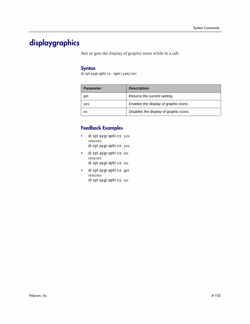
System Commands
Polycom, Inc. 4–105
displaygraphicsSets or gets the display of graphic icons while in a call.
Syntaxdisplaygraphics <get|yes|no>
Feedback Examples• displaygraphics yes
returnsdisplaygraphics yes
• displaygraphics noreturnsdisplaygraphics no
• displaygraphics getreturnsdisplaygraphics no
Parameter Description
get Returns the current setting.
yes Enables the display of graphic icons.
no Disables the display of graphic icons.

Integrator’s Reference Manual for Polycom HDX Systems
4–106 Polycom, Inc.
displayipextSets or gets the display of the IP extension field. This extension is needed when placing a call through a gateway.
Syntaxdisplayipext <get|yes|no>
Feedback Examples• displayipext yes
returnsdisplayipext yes
• displayipext noreturnsdisplayipext no
• displayipext getreturnsdisplayipext no
CommentsWhen this option is selected, the extension field is visible on the Home screen.
Parameter Description
get Returns the current setting.
yes Enables the display of the IP extension.
no Enables the display of the IP extension.

System Commands
Polycom, Inc. 4–107
displayipisdninfo (deprecated)Sets or gets the display of IP and ISDN information on the Home screen. This command has been deprecated. Polycom recommends using the ipisdninfo command on page 4-196.
Syntaxdisplayipisdninfo <yes|no|both|ip-only|isdn-only|none|get>
Feedback Examples• displayipisdninfo yes
returnsdisplayipisdninfo both
• displayipisdninfo noreturnsdisplayipisdninfo none
• displayipisdninfo ip-onlyreturnsdisplayipisdninfo ip-only
• displayipisdninfo getreturnsdisplayipisdninfo ip-only
Parameter Description
yes Enables the display of both IP and ISDN information. Provides feedback both.
no Disables the display of IP and ISDN information. Provides feedback none.
both Enables the display of both IP and ISDN information.
ip-only Enables the display of IP information.
isdn-only Enables the display of ISDN information.
none Disables the display of IP and ISDN information.
get Returns the current setting.

Integrator’s Reference Manual for Polycom HDX Systems
4–108 Polycom, Inc.
displayparamsOutputs a list of system settings.
Syntaxdisplayparams
Feedback Examples• displayparams
returnssystemname Polycom HDX Demohostname <empty>ipaddress 192.168.1.101version “2.5”serialnum 82065205E72EC1displaygraphics novgaresolution 60hz1280x720vgaphase 32numberofmonitors 2monitor1 16:9monitor2 16:9vgahorizpos 128vgavertpos 128cameradirection normalfarcontrolnearcamera yesprimarycamera 1backlightcompensation notelecountrycode <empty>teleareacode <empty>telenumber <empty>roomphonenumber <empty>echocancellerred noechocancellerwhite nomuteautoanswer yesvcraudioout novcrrecordsource content-or-autoredlineinput vcrwhitelineinput vcrredlinelevel 5whitelinelevel 5lineoutputs monitorlineoutputslevel 5mpmode autosleeptime 1sleeptext <empty>rs232 mode camera_ptz

System Commands
Polycom, Inc. 4–109
rs232 baud 9600rs232port1 mode camera_ptzrs232port1 baud 9600

Integrator’s Reference Manual for Polycom HDX Systems
4–110 Polycom, Inc.
dnsSets or gets the configuration for up to four DNS servers.
Syntaxdns get {1..4}dns set {1..4} “xxx.xxx.xxx.xxx”
Feedback Examples• dns set 1 192.168.1.205
returnsdns 1 192.168.1.205
CommentsAfter making a change, you must restart the system for the setting to take effect. These values cannot be set if the system is in DHCP client mode.
Parameter Description
get Returns the current IP address of the specified server.
A server identification number {1..4} is required.
{1..4} Specifies the server identification number.
set Sets the IP address of the specified DNS server when followed by the “xxx.xxx.xxx.xxx” parameter.
A server identification number {1..4} is required.
“xxx.xxx.xxx.xxx” Specifies the IP address for the specified server.

System Commands
Polycom, Inc. 4–111
dsrSets or gets the configuration of the DSR serial interface control signal (data set ready). This command is only applicable if you have a V.35 network interface connected to your system.
Syntaxdsr <get|normal|inverted>
Feedback Examples• dsr normal
returnsdsr normal
• dsr invertedreturnsdsr inverted
• dsr getreturnsdsr inverted
CommentsThe default setting for this signal is “normal”.
Parameter Description
get Returns the current setting.
normal Sets the signal to normal (high voltage is logic 1).
inverted Sets the signal to inverted (low voltage is logic 1).
Integrator’s Reference Manual for Polycom HDX Systems
4–112 Polycom, Inc.
dsranswerSets or gets the configuration of the DSR serial interface control signal to indicate an incoming call. This command is only applicable if you have a V.35 network interface connected to your system.
Syntaxdsranswer <get|on|off>
Feedback Examples• dsranswer on
returnsdsranswer on
• dsranswer offreturnsdsranswer off
• dsranswer getreturnsdsranswer off
Parameter Description
get Returns the current setting.
on Turns on the option.
off Turns off the option.

System Commands
Polycom, Inc. 4–113
dtrSets or gets the configuration of the DTR serial interface control signal (data terminal ready). This command is only applicable if you have a V.35 network interface connected to your system.
Syntaxdtr <get|normal|inverted|on>
Feedback Examples• dtr normal
returnsdtr normal
• dtr invertedreturnsdtr inverted
• dtr onreturnsdtr on
• dtr getreturnsdtr on
CommentsThe default setting for the signal is “normal”.
Parameter Description
get Returns the current setting.
normal Sets the signal to normal (high voltage is logic 1).
inverted Sets the signal to inverted (low voltage is logic 1).
on Sets constant high voltage. If this option is selected, inverted is not an option.

Integrator’s Reference Manual for Polycom HDX Systems
4–114 Polycom, Inc.
dualmonitorSets or gets whether video is displayed using dual monitor emulation, or split-screen mode, when using one monitor.
Syntaxdualmonitor <get|yes|no>
Feedback Examples• dualmonitor yes
returnsdualmonitor yes
• dualmonitor noreturnsdualmonitor no
• dualmonitor getreturnsdualmonitor no
Parameter Description
get Returns the current setting.
yes Enables dual monitor emulation.
no Disables dual monitor emulation.

System Commands
Polycom, Inc. 4–115
dynamicbandwidthSets or gets the use of dynamic bandwidth allocation for Quality of Service.
Syntaxdynamicbandwidth <get|yes|no>
Feedback Examples• dynamicbandwidth yes
returnsdynamicbandwidth yes
• dynamicbandwidth noreturnsdynamicbandwidth no
• dynamicbandwidth getreturnsdynamicbandwidth no
CommentsThe system’s dynamic bandwidth function automatically finds the optimum line speed for a call. If you experience excessive packet loss while in a call, the dynamic bandwidth function decrements the line speed until there is no packet loss. This is supported in calls with end points that also support dynamic bandwidth.
Parameter Description
get Returns the current setting.
yes Enables the dynamic bandwidth option.
no Disables the dynamic bandwidth option.

Integrator’s Reference Manual for Polycom HDX Systems
4–116 Polycom, Inc.
e164extSets or gets an H.323 (IP) extension, also known as an E.164 name.
Syntaxe164ext gete164ext set “e.164name”
Feedback Examples• e164ext set
returnse164ext <empty>
• e164ext set 7878returnse164ext 7878
• e164ext get 7878returnse164ext 7878
CommentsThe extension number is associated with a specific LAN device.
Parameter Description
get Returns the current setting.
set Sets the E.164 extension when followed by the “e.164name” parameter. To erase the current setting, omit “e.164name”.
“e.164name” A valid E.164 extension (usually a four-digit number).

System Commands
Polycom, Inc. 4–117
echoPrints “string” back to the API client screen.
Syntaxecho “string”
Feedback Examples• echo End of abk range results
returnsEnd of abk range results
CommentsCertain API commands print multiple lines without any delimiter string to notify end of command response. This forces a control panel program to guess when the command's response string is going to end. In those scenarios, control panel can issue the legacy command followed by echo command with a delimiter string of its choosing. Once legacy command's response ends, echo command gets processed, which results in the delimiter string printed to the API client.
Parameter Description
“string” Text to be printed to the screen.

Integrator’s Reference Manual for Polycom HDX Systems
4–118 Polycom, Inc.
echocancellerSets or gets the configuration of echo cancellation, which prevents users from hearing their voices loop back from the far site.
Syntaxechocanceller <get|yes|no>
Feedback Examples• echocanceller yes
returnsechocancellerred yesechocancellerwhite yes
• echocanceller noreturnsechocancellerred noechocancellerwhite no
• echocanceller getreturnsechocancellerred noechocancellerwhite no
CommentsThis option is enabled by default. Polycom strongly recommends that you do not turn off echo cancellation except when using an external microphone system with its own built-in echo cancellation.
Parameter Description
get Returns the current setting.
yes Enables the echo canceller option.
no Disables the echo canceller option.

System Commands
Polycom, Inc. 4–119
echoreplySets or gets the system’s ability to send an Echo Reply message in response to an Echo Request message sent to an IPv6 multicast/anycast address.
Syntaxechoreply <get|yes|no>
Feedback Examples• echoreply get
returnsechoreply yes
• echoreply noreturnsechoreply no
CommentsThis setting is applicable for both IPv4 and IPv6 configurations. The number of responses may be traffic-conditioned to limit the effect of a denial of service attack.
After making a change, you must restart the system for the setting to take effect.
Parameter Description
get Returns the current setting.
yes Enables the echo reply option.
no Disables the echo reply option.

Integrator’s Reference Manual for Polycom HDX Systems
4–120 Polycom, Inc.
enablefirewalltraversalSets or gets the Enable H.460 Firewall Traversal setting. This feature requires an Edgewater session border controller that supports H.460.
Syntaxenablefirewalltraversal <get|on|off>
Feedback Examples• enablefirewalltraversal on
returnsenablefirewalltraversal on
• enablefirewalltraversal offreturnsenablefirewalltraversal off
• enablefirewalltraversal getreturnsenablefirewalltraversal off
Parameter Description
get Returns the current setting.
on Enables the firewall traversal feature.
off Disables the firewall traversal feature.

System Commands
Polycom, Inc. 4–121
enablekeyboardnoisereductionSets or gets the Enable Keyboard Noise Reduction setting.
Syntaxenablekeyboardnoisereduction <get|yes|no>
Feedback Examples• enablekeyboardnoisereduction yes
returnsenablekeyboardnoisereduction yes
• enablekeyboardnoisereduction noreturnsenablekeyboardnoisereduction no
• enablekeyboardnoisereduction getreturnsenablekeyboardnoisereduction no
Parameter Description
get Returns the current setting.
yes Enables keyboard noise reduction.
no Disables keyboard noise reduction.
Integrator’s Reference Manual for Polycom HDX Systems
4–122 Polycom, Inc.
enablelivemusicmodeSets or gets the Enable Live Music Mode setting.
Syntaxenablelivemusicmode <get|yes|no>
Feedback Examples• enablelivemusicmode yes
returnsenablelivemusicmode yes
• enablelivemusicmode noreturnsenablelivemusicmode no
• enablelivemusicmode getreturnsenablelivemusicmode no
Parameter Description
get Returns the current setting.
yes Enables live music mode.
no Disables live music mode.
System Commands
Polycom, Inc. 4–123
enablepvecSets or gets the Polycom Video Error Concealment (PVEC) setting on the system.
Syntaxenablepvec <get|yes|no>
Feedback Examples• enablepvec yes
returnsenablepvec yes
• enablepvec noreturnsenablepvec no
• enablepvec getreturnsenablepvec no
CommentsThis option is enabled by default.
Parameter Description
get Returns the current setting.
yes Enables the PVEC option.
no Disables the PVEC option.

Integrator’s Reference Manual for Polycom HDX Systems
4–124 Polycom, Inc.
enablersvpSets or gets the RSVP (Resource Reservation Setup Protocol) setting on the system, which requests that routers reserve bandwidth along an IP connection path.
Syntaxenablersvp <get|yes|no>
Feedback Examples• enablersvp yes
returnsenablersvp yes
• enablersvp noreturnsenablersvp no
• enablersvp getreturnsenablersvp no
CommentsThis option is enabled by default.
Parameter Description
get Returns the current setting.
yes Enables the RSVP option.
no Disables the RSVP option.

System Commands
Polycom, Inc. 4–125
enablesnmpSets or gets the SNMP configuration.
Syntaxenablesnmp <get|yes|no>
Feedback Examples• enablesnmp yes
returnsenablesnmp yes
• enablesnmp noreturnsenablesnmp no
• enablesnmp getreturnsenablesnmp no
CommentsAfter making a change, you must restart the system for the setting to take effect.
Parameter Description
get Returns the current setting.
yes Enables the SNMP option.
no Disables the SNMP option.

Integrator’s Reference Manual for Polycom HDX Systems
4–126 Polycom, Inc.
encryptionSets or gets the AES encryption mode for the system.
Syntaxencryption <get|yes|no|requiredvideocallsonly|requiredallcalls>
Feedback Examples• encryption yes
returnsencryption yes
• encryption noreturnsencryption no
• encryption getreturnsencryption no
• encryption requiredvideocallsonlyreturnsencryption requiredvideocallsonly
• encryption requiredallcallsreturnsencryption requiredallcalls
Parameter Description
get Returns the current setting.
yes Use encryption when the far site is capable of encryption.
Note: This parameter is called “When Available” in the user interface.
no Disables encryption.
Note: This parameter is called “Off” in the user interface.
requiredvideocallsonly Enforces encryption on all video endpoints. Any video calls to or from systems that do not have encryption enabled are not connected. Audio-only calls are connected.
requiredallcalls Enforces encryption on all endpoints. Any video or audio calls to or from systems that do not have encryption enabled are rejected and are not connected.

System Commands
Polycom, Inc. 4–127
CommentsYou cannot use this command while a call is in progress. Using this command while the system is in a call returns an “error: command has illegal parameters” message.

Integrator’s Reference Manual for Polycom HDX Systems
4–128 Polycom, Inc.
exitEnds the API command session.
Syntaxexit
Feedback Examples• exit
returnsConnection to host lost.
CommentsThis command ends a Telnet session. For serial sessions, this command effectively starts a new session.

System Commands
Polycom, Inc. 4–129
exportdirectoryExports a directory in XML format.
Syntaxexportdirectory
Feedback Exampleexportdirectory
returns
exportdirectory started
<?xml version="1.0" encoding="UTF-8" ?>
<addresses>
<entrytype type="entry" name="Polycom Austin USA IP" filename="Polycom_Austin_USA_IP.abk" uniqueid="Polycom_Austin_USA_IP.abk">
<address filename="Polycom_Austin_USA_IP.abk" langid="" displayname="" name="Polycom Austin USA IP">
<h323 address="lobby.austin.polycom.com" speed="256"/>
</address>
</entrytype>
<entrytype type="entry" name="Polycom Hong Kong" filename="Polycom_Hong_Kong.abk" uniqueid="Polycom_Hong_Kong.abk">
<address filename="Polycom_Hong_Kong.abk" langid="" displayname="" name="Polycom Hong Kong">
<isdn country_code="852" area_code="2876" numberA="9466" numberB="9466" speed="2x64"/>
</address>
</addresses>
</xml>
exportdirectory done
CommentsWhen importing directory data back into the system, use the data in its entirety (not edited in any form). There is information that is used by the system to determine what type (XML or CSV) of data is being imported.

Integrator’s Reference Manual for Polycom HDX Systems
4–130 Polycom, Inc.
exportdirectory done as the last line of returned data indicates that all directory data has been exported.
Do not use exportdirectory to interpret the data that is returned. Simply store and use the data as input to the importdirectory command or import directory utility in the web interface. The format of the exported directory data might change in future software releases and any application attempting to interpret the data could find its ability to do so compromised in later releases of Polycom HDX software.
Additional Usage Notes:
• Polycom HDX systems running software version 2.6 or later can import directory data exported from systems running 2.6 and earlier versions.
• Polycom HDX systems running software versions earlier than 2.6 cannot import directory data exported by systems running software version 2.6 or later.
See Alsoimportdirectory command on page 4-187.
System Commands
Polycom, Inc. 4–131
exportprofileExports system and user profile information in a CSV format. The output is available through a telnet or serial port connection.
Syntaxexportprofile
Feedback Exampleexportprofile startedh323name,s8whdaccelerator,BrutusTavayaenabled,""systemsoftwareversion_prev,2.6.0ipmaxincoming,4096speakervolume,25sysname,s8wspeedstranslated,Auto~128~256~384~512~768~1024~1472~1920~4096directoryinfoupdated,Truepwcreatetimeminremoteuser0,0. . . buildmodel,ROOSEVELThomebutton,MAKEACALLdialnumberext,""mp8enabled,""lastloginfromadmin,Localtimezone,CSTpresence,AVAILABLEprofilechecksum,16813327827exportprofile done
CommentsWhen importing profile data back into the system, use the data in its entirety (not edited in any form). The system may use the checksum utility to verify of integrity of the data when imported back into the system.
exportprofile done as the last line of returned data indicates that all the profile data has been exported.
Do not use exportprofile to interpret the data that is returned. Simply store and use the data as input to the importprofile command or import profile utility in the web interface. The format of the exported data might change in future software releases and any application attempting to interpret the data could find its ability to do so compromised in later releases of Polycom HDX software.

Integrator’s Reference Manual for Polycom HDX Systems
4–132 Polycom, Inc.
See Alsoimportprofile command on page 4-190.

System Commands
Polycom, Inc. 4–133
farcontrolnearcameraSets or gets far control of the near camera, which allows far sites to control the camera on your system.
Syntaxfarcontrolnearcamera <get|yes|no>
Feedback Examples• farcontrolnearcamera yes
returnsfarcontrolnearcamera yes
• farcontrolnearcamera noreturnsfarcontrolnearcamera no
• farcontrolnearcamera getreturnsfarcontrolnearcamera no
Parameter Description
get Returns the current setting.
yes Allows the far site to control the near camera if the far site has this capability.
no Disables far control of the near camera.

Integrator’s Reference Manual for Polycom HDX Systems
4–134 Polycom, Inc.
farnametimedisplaySets or gets the length of time the far-site name is displayed on the system.
Syntaxfarnametimedisplay offfarnametimedisplay <get|on|15|30|60|120>
Feedback Examples• farnametimedisplay off
returnsfarnametimedisplay off
• farnametimedisplay onreturnsfarnametimedisplay on
• farnametimedisplay 60returnsfarnametimedisplay 60
• farnametimedisplay getreturnsfarnametimedisplay 60
Parameter Description
off Disables the far site name display.
get Returns the current setting.
on Displays the far site name for the duration of the call.
15|30|60|120 Specifies the number of seconds to display the far site name at the beginning of a call.
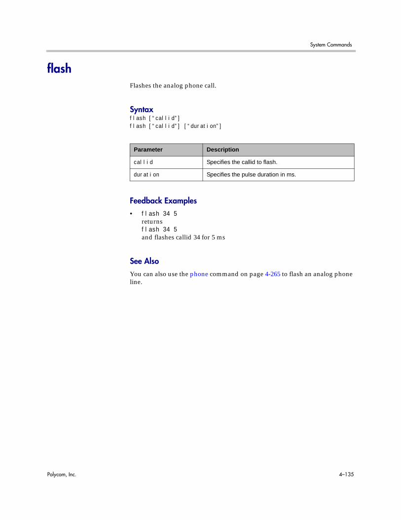
System Commands
Polycom, Inc. 4–135
flashFlashes the analog phone call.
Syntaxflash [“callid”]flash [“callid”] [“duration”]
Feedback Examples• flash 34 5
returnsflash 34 5and flashes callid 34 for 5 ms
See AlsoYou can also use the phone command on page 4-265 to flash an analog phone line.
Parameter Description
callid Specifies the callid to flash.
duration Specifies the pulse duration in ms.

Integrator’s Reference Manual for Polycom HDX Systems
4–136 Polycom, Inc.
gabk (deprecated)Returns global directory (address book) entries. This command has been deprecated. Polycom recommends using the gaddrbook command on page 4-141.
Syntaxgabk allgabk batch {0..59}gabk batch define “start_no” “stop_no”gabk batch search “pattern” “count”gabk letter {a..z}gabk range “start_no” “stop_no”gabk refresh
Parameter Description
all Returns all entries in the global directory.
batch Returns a batch of 20 global directory entries. Requires a batch number, which must be an integer in the range {0..59}.
define Returns a batch of entries in the range defined by “start_no” to “stop_no.” Polycom recommends using gabk range instead of this command.
“start_no” Specifies the beginning of the range of entries to return.
“stop_no” Specifies the end of the range of entries to return.
search Specifies a batch search.
“pattern” Specifies pattern to match for the batch search.
“count” Specifies the number of entries to list that match the pattern.
letter Returns entries beginning with the letter specified from the range {a..z}. Requires one or two alphanumeric characters. Valid characters are:
- _ / ; @ , . \ 0 through 9, a through z
range Returns global directory entries from “start_no” through “stop_no”. Requires two integers.
refresh Gets a more current copy of the global directory.
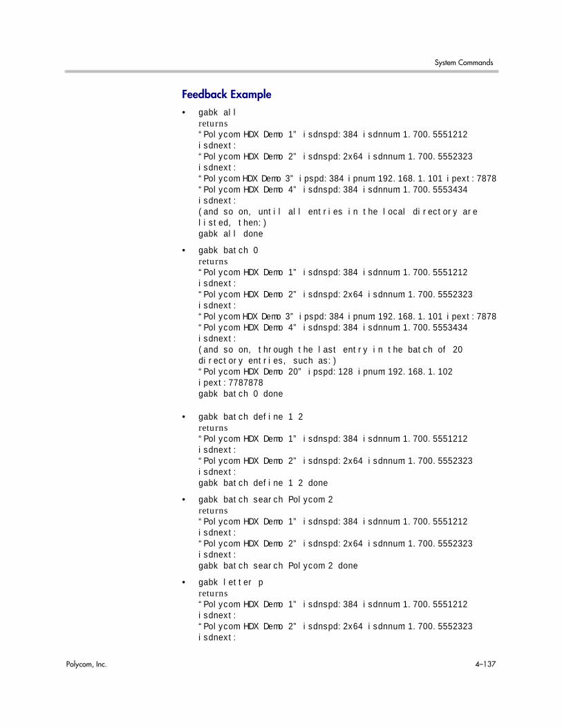
System Commands
Polycom, Inc. 4–137
Feedback Example• gabk all
returns“Polycom HDX Demo 1” isdnspd:384 isdnnum:1.700.5551212 isdnext:“Polycom HDX Demo 2” isdnspd:2x64 isdnnum:1.700.5552323 isdnext:“Polycom HDX Demo 3” ipspd:384 ipnum:192.168.1.101 ipext:7878“Polycom HDX Demo 4” isdnspd:384 isdnnum:1.700.5553434 isdnext:(and so on, until all entries in the local directory are listed, then:)gabk all done
• gabk batch 0returns“Polycom HDX Demo 1” isdnspd:384 isdnnum:1.700.5551212 isdnext:“Polycom HDX Demo 2” isdnspd:2x64 isdnnum:1.700.5552323 isdnext:“Polycom HDX Demo 3” ipspd:384 ipnum:192.168.1.101 ipext:7878“Polycom HDX Demo 4” isdnspd:384 isdnnum:1.700.5553434 isdnext:(and so on, through the last entry in the batch of 20 directory entries, such as:)“Polycom HDX Demo 20” ipspd:128 ipnum:192.168.1.102 ipext:7787878gabk batch 0 done
• gabk batch define 1 2returns“Polycom HDX Demo 1” isdnspd:384 isdnnum:1.700.5551212 isdnext:“Polycom HDX Demo 2” isdnspd:2x64 isdnnum:1.700.5552323 isdnext:gabk batch define 1 2 done
• gabk batch search Polycom 2returns“Polycom HDX Demo 1” isdnspd:384 isdnnum:1.700.5551212 isdnext:“Polycom HDX Demo 2” isdnspd:2x64 isdnnum:1.700.5552323 isdnext:gabk batch search Polycom 2 done
• gabk letter preturns“Polycom HDX Demo 1” isdnspd:384 isdnnum:1.700.5551212 isdnext:“Polycom HDX Demo 2” isdnspd:2x64 isdnnum:1.700.5552323 isdnext:

Integrator’s Reference Manual for Polycom HDX Systems
4–138 Polycom, Inc.
“Polycom HDX Demo 3” ipspd:384 ipnum:192.168.1.101 ipext:7878“Polycom HDX Demo 4” isdnspd:384 isdnnum:1.700.5553434 isdnext:(and so on, to include all entries in the batch that begin with p, then:)gabk letter p done
• gabk range 1 2returns“Polycom HDX Demo 1” isdnspd:384 isdnnum:1.700.5551212 isdnext:“Polycom HDX Demo 2” isdnspd:2x64 isdnnum:1.700.5552323 isdnext:gabk range 1 2 done
CommentsWhen the system is registered with the LDAP directory server, all gabk commands return the response, command not supported.
gabk entries are entries stored in the global directory. In the user interface, the address book and global address book features are referred to as the global directory.
See AlsoTo return local directory entries, use the abk (deprecated) command on page 4-9.

System Commands
Polycom, Inc. 4–139
gabpasswordSets the password to gain access to the Global Directory Server.
Syntax
gabpassword set [“password”]
Feedback Examples• gabpassword set gabpass
returnsgabpassword gabpass
CommentsThis command cannot be used unless the Remote Access password in the user interface has been set.
Parameter Description
set Sets the GDS password to “password”. To erase the current setting, omit “password”.
“password” Password to access the GDS server. Valid characters are: a through z (lower and uppercase), -, _, @, /, ;, ,, ., \, 0 through 9. Enclose the string in quotation marks if it includes spaces.
This command might not return the current password in correct case-sensitive format.

Integrator’s Reference Manual for Polycom HDX Systems
4–140 Polycom, Inc.
gabserveripSets or gets the IP address of the Global Directory Server.
Syntaxgabserverip <get|set>
Feedback Examples• gabserverip set
returnsgabserverip <empty>
• gabserverip set gab.polycom.comreturnsgabserverip gab.polycom.com
• gabserverip getreturnsgabserverip gab.polycom.com
Parameter Description
get Returns the current setting.
set Sets the GDS server’s IP address when followed by the parameter “xxx.xxx.xxx.xxx”. To erase the current setting, omit the “xxx.xxx.xxx.xxx” parameter.

System Commands
Polycom, Inc. 4–141
gaddrbookReturns global directory (address book) entries.
Syntaxgaddrbook allgaddrbook batch {0..59}gaddrbook batch define “start_no” “stop_no”gaddrbook batch search “pattern” “count”gaddrbook letter {a..z}gaddrbook range “start_no” “stop_no”gaddrbook refresh
Feedback Examples• gaddrbook all
returnsgaddrbook 0. “Polycom HDX Demo 1” isdn_spd:384
Parameter Description
all Returns all the entries in the global directory.
batch Returns a batch of 20 global directory entries. Requires a batch number, which must be an integer in the range {0..59}.
define Returns a batch of entries in the range defined by “start_no” to “stop_no.”
search Specifies a batch search.
“pattern” Specifies a pattern to match for the batch search.
“count” Specifies the number of entries to list that match the pattern.
letter Returns entries beginning with the letter specified from the range {a..z}. Requires one or two alphanumeric characters. Valid characters are:- _ / ; @ , . \ 0 through 9a through z
range Returns global directory entries numbered “start_no” through “stop_no”. Requires two integers.
“start_no” Specifies the beginning of the range of entries to return.
“stop_no” Specifies the end of the range of entries to return.
refresh Gets a more current copy of the global directory.

Integrator’s Reference Manual for Polycom HDX Systems
4–142 Polycom, Inc.
isdn_num:1.700.5551212 isdn_ext:gaddrbook 1. “Polycom HDX Demo 2” h323_spd:384 h323_num:192.168.1.101 h323_ext:7878gaddrbook 2. “Polycom HDX Demo 3” sip_spd:384 sip_num:[email protected] 3. “Polycom HDX Demo 3” phone_num:1.512.5121212(and so on, until all entries in the global directory are listed, then:)gaddrbook all done
• gaddrbook batch 0returnsgaddrbook 0. “Polycom HDX Demo 1” isdn_spd:384 isdn_num:1.700.5551212 isdn_ext:gaddrbook 1. “Polycom HDX Demo 2” h323_spd:384 h323_num:192.168.1.101 h323_ext:7878gaddrbook 2. “Polycom HDX Demo 3” sip_spd:384 sip_num:[email protected] 3. “Polycom HDX Demo 3” phone_num:1.512.5121212(and so on, through the last entry in the batch of 20 directory entries, such as:)gaddrbook 19. “Polycom HDX Demo 20” h323_spd:384 h323_num:192.168.1.120 h323_ext:gaddrbook batch 0 done
• gaddrbook batch define 0 2returnsgaddrbook 0. “Polycom HDX Demo 1” isdn_spd:384 isdn_num:1.700.5551212 isdn_ext:gaddrbook 1. “Polycom HDX Demo 2” h323_spd:384 h323_num:192.168.1.101 h323_ext:7878gaddrbook 2. “Polycom HDX Demo 3” sip_spd:384 sip_num:[email protected] batch define 0 2 done
• gaddrbook batch search Polycom 3returnsgaddrbook 0. “Polycom HDX Demo 1” isdn_spd:384 isdn_num:1.700.5551212 isdn_ext:gaddrbook 1. “Polycom HDX Demo 2” h323_spd:384 h323_num:192.168.1.101 h323_ext:7878gaddrbook 2. “Polycom HDX Demo 3” sip_spd:384 sip_num:[email protected] batch search Polycom 3 done
• gaddrbook letter preturnsgaddrbook 0. “Polycom HDX Demo 1” isdn_spd:384 isdn_num:1.700.5551212 isdn_ext:gaddrbook 1. “Polycom HDX Demo 2” h323_spd:384 h323_num:192.168.1.101 h323_ext:7878gaddrbook 2. “Polycom HDX Demo 3” sip_spd:384

System Commands
Polycom, Inc. 4–143
sip_num:[email protected] 3. “Polycom HDX Demo 3” phone_num:1.512.5121212gaddrbook 19. “Polycom HDX Demo 20” h323_spd:384 h323_num:192.168.1.120 h323_ext:gaddrbook letter p done
• gaddrbook range 0 2returnsgaddrbook 0. “Polycom HDX Demo 1” isdn_spd:384 isdn_num:1.700.5551212 isdn_ext:gaddrbook 1. “Polycom HDX Demo 2” h323_spd:384 h323_num:192.168.1.101 h323_ext:7878gaddrbook 2. “Polycom HDX Demo 3” sip_spd:384 sip_num:[email protected] range 0 2 done
CommentsEntries with multiple addresses (for example, an H.323 address and an ISDN number) return each address type on separate lines with an incremented record number.
When the system is registered with the LDAP directory server, only the gaddrbook batch search “pattern” “count” is supported. All other gaddrbook commands return the response, command not supported.
When the system is registered with the Polycom GDS directory server, all of the gaddrbook commands and parameters are supported.
gaddrbook entries are stored in the global directory (address book).

Integrator’s Reference Manual for Polycom HDX Systems
4–144 Polycom, Inc.
gatekeeperipSets or gets the IP address of the gatekeeper.
Syntaxgatekeeperip getgatekeeperip set [“xxx.xxx.xxx.xxx”]
Feedback Examples• gatekeeperip set 192.168.1.205
returnsgatekeeperip 192.168.1.205
• gatekeeperip getreturnsgatekeeperip 192.168.1.205
Note: The gatekeeperip get command feedback may include the port number after the IP address.
Parameter Description
get Returns the current setting.
set Sets the gatekeeper IP address when followed by the “xxx.xxx.xxx.xxx” parameter. To erase the current setting, omit “xxx.xxx.xxx.xxx”.
“xxx.xxx.xxx.xxx” IP address of the gatekeeper.

System Commands
Polycom, Inc. 4–145
gatewayareacodeSets or gets the gateway area code.
Syntaxgatewayareacode getgatewayareacode set [“areacode”]
Feedback Examples• gatewayareacode get
returnsgatewayareacode <empty>
• gatewayareacode set 512 returnsgatewayareacode 512
• gatewayareacode get returnsgatewayareacode 512
Parameter Description
get Returns the area code for the gateway.
set Sets the area code when followed by the “areacode” parameter. To erase the current setting, omit “areacode”.
“areacode” Numeric string specifying the area code.
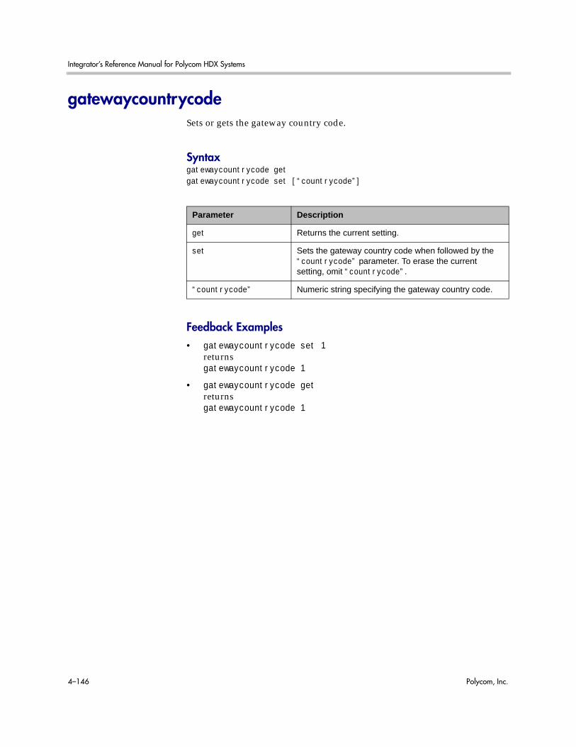
Integrator’s Reference Manual for Polycom HDX Systems
4–146 Polycom, Inc.
gatewaycountrycodeSets or gets the gateway country code.
Syntaxgatewaycountrycode getgatewaycountrycode set [“countrycode”]
Feedback Examples• gatewaycountrycode set 1
returnsgatewaycountrycode 1
• gatewaycountrycode getreturnsgatewaycountrycode 1
Parameter Description
get Returns the current setting.
set Sets the gateway country code when followed by the “countrycode” parameter. To erase the current setting, omit “countrycode”.
“countrycode” Numeric string specifying the gateway country code.

System Commands
Polycom, Inc. 4–147
gatewayextSets or gets the gateway extension number.
Syntaxgatewayext getgatewayext set [“extension”]
Feedback Examples• gatewayext set 59715
returnsgatewayext 59715
• gatewayext getreturnsgatewayext 59715
Parameter Description
get Returns the current setting.
set Sets the gateway extension number when followed by the “extension” parameter. To reset the default value, omit “extension”.
“extension” Numeric string specifying the gateway extension.
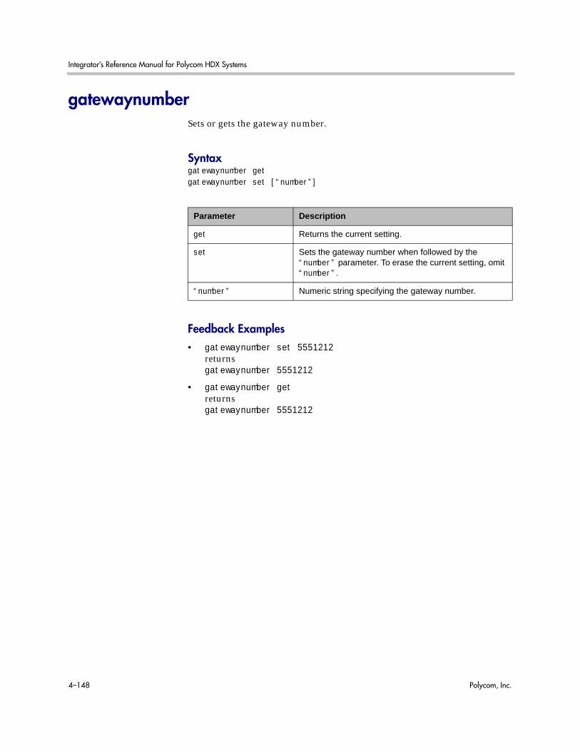
Integrator’s Reference Manual for Polycom HDX Systems
4–148 Polycom, Inc.
gatewaynumberSets or gets the gateway number.
Syntaxgatewaynumber getgatewaynumber set [“number”]
Feedback Examples• gatewaynumber set 5551212
returnsgatewaynumber 5551212
• gatewaynumber getreturnsgatewaynumber 5551212
Parameter Description
get Returns the current setting.
set Sets the gateway number when followed by the “number” parameter. To erase the current setting, omit “number”.
“number” Numeric string specifying the gateway number.
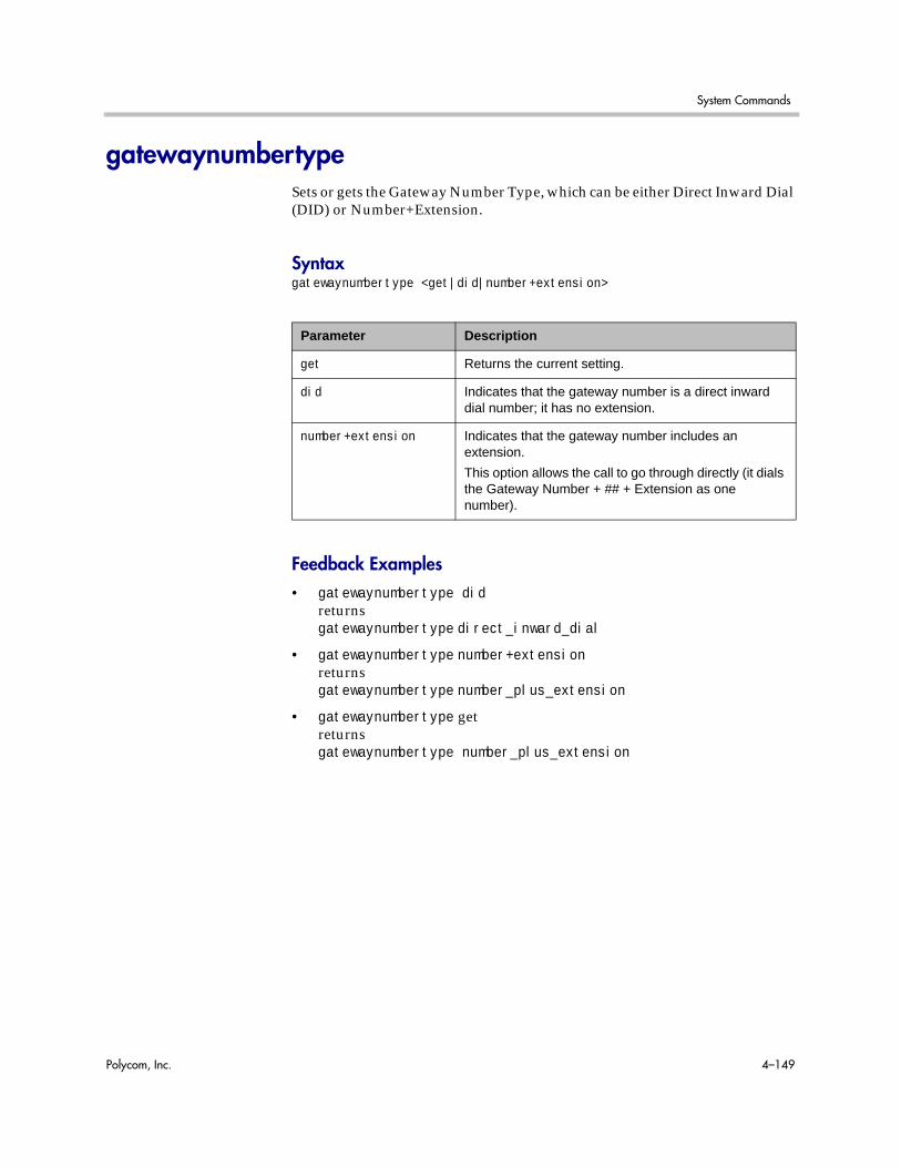
System Commands
Polycom, Inc. 4–149
gatewaynumbertypeSets or gets the Gateway Number Type, which can be either Direct Inward Dial (DID) or Number+Extension.
Syntaxgatewaynumbertype <get|did|number+extension>
Feedback Examples• gatewaynumbertype did
returnsgatewaynumbertype direct_inward_dial
• gatewaynumbertype number+extensionreturnsgatewaynumbertype number_plus_extension
• gatewaynumbertype getreturnsgatewaynumbertype number_plus_extension
Parameter Description
get Returns the current setting.
did Indicates that the gateway number is a direct inward dial number; it has no extension.
number+extension Indicates that the gateway number includes an extension.
This option allows the call to go through directly (it dials the Gateway Number + ## + Extension as one number).

Integrator’s Reference Manual for Polycom HDX Systems
4–150 Polycom, Inc.
gatewayprefixSets or gets the gateway prefixes for the corresponding speeds.
Syntaxgatewayprefix get “valid speed”gatewayprefix set “valid speed” [“value”]
Feedback Examples• gatewayprefix set 168 90
returnsgatewayprefix 168 90
• gatewayprefix get 168returnsgatewayprefix 168 90
CommentsSome gateways require a number to be prepended (prefix) to the gateway number. The prefix identifies which gateway is used to dial a call at a particular data rate.
Parameter Description
get When followed by the “valid speed” parameter, returns the current value for this speed.
“valid speed” Valid speeds are: 56, 64, 2x56, 112, 2x64, 128, 168, 192, 224, 256, 280, 320, 336, 384, 392, 7x64, 8x56, 504, 512, 560, 576, 616, 640, 672, 704, 728, 768, 784, 832, 840, 16x56, 14x64, 952, 960, 1008, 1024, 1064, 1088, 1120, 1152, 1176, 1216, 1232, 1280, 1288, 24x56, 21x64, 1400, 1408, 1456, 1472, 1512, 1536, 1568, 1600, 1624, 1664, 1680, 1728, 1736, 32x56, 28x64, 1848, 1856, 1904, and 1920 kbps.
set Sets the gateway prefix when followed by the “value” parameter. To erase the current setting, omit “value”.
“value” Prefix (code) used for a particular call speed. Consult your gateway instruction manual to determine which codes are appropriate.

System Commands
Polycom, Inc. 4–151
gatewaysetupLists all available speeds and values at once.
Syntaxgatewaysetup
Feedback Examples• gatewaysetup
returns56 <empty> <empty>64 #14 #162x56 #222 #333112 #444 #5552x64 <empty> <empty>and so on.

Integrator’s Reference Manual for Polycom HDX Systems
4–152 Polycom, Inc.
gatewaysuffixSets or gets the gateway suffix.
Syntaxgatewaysuffix get “valid speed”gatewaysuffix set “valid speed” [“value”]
Feedback Examples• gatewaysuffix set 192 11
returnsgatewaysuffix 192 11
• gatewaysuffix get 192returnsgatewaysuffix 192 11
CommentsSome gateways require a number to be appended (suffix) to the gateway number. The suffix identifies which gateway is used to dial a call at a particular data rate.
Parameter Description
get Returns the current value for this speed.
“valid speed” Valid speeds are: 56, 64, 2x56, 112, 2x64, 128, 168, 192, 224, 256, 280, 320, 336, 384, 392, 7x64, 8x56, 504, 512, 560, 576, 616, 640, 672, 704, 728, 768, 784, 832, 840, 16x56, 14x64, 952, 960, 1008, 1024, 1064, 1088, 1120, 1152, 1176, 1216, 1232, 1280, 1288, 24x56, 21x64, 1400, 1408, 1456, 1472, 1512, 1536, 1568, 1600, 1624, 1664, 1680, 1728, 1736, 32x56, 28x64, 1848, 1856, 1904, and 1920 kbps.
set Sets the gateway suffix when followed by the “value” parameter. To erase the current setting, omit “value”.
“value” Suffix (code) used for a particular call speed. Consult your gateway instruction manual to determine which codes are appropriate. Use quotation marks around a compound name or strings that contain spaces. For example: “united states” or “111 222 333”.

System Commands
Polycom, Inc. 4–153
gdsdirectorySets or gets whether the Polycom GDS directory server is enabled.
Syntaxgdsdirectory <get|yes|no>
Feedback Examples• gdsdirectory get
returnsgdsdirectory yes
• gdsdirectory noreturnsgdsdirectory no
CommentsEach Polycom system supports a single global directory server at any given time. Therefore, enabling the Polycom GDS directory server automatically disables any other global directory server, such as the LDAP directory server, that is enabled.
If the Polycom GDS directory server and another directory server are defined on the system, the Polycom GDS directory server becomes the default directory server after upgrading the system software.
Parameter Description
get Returns the current setting.
yes Enables the Polycom GDS directory server.
no Disables the Polycom GDS directory server. This is the default setting.
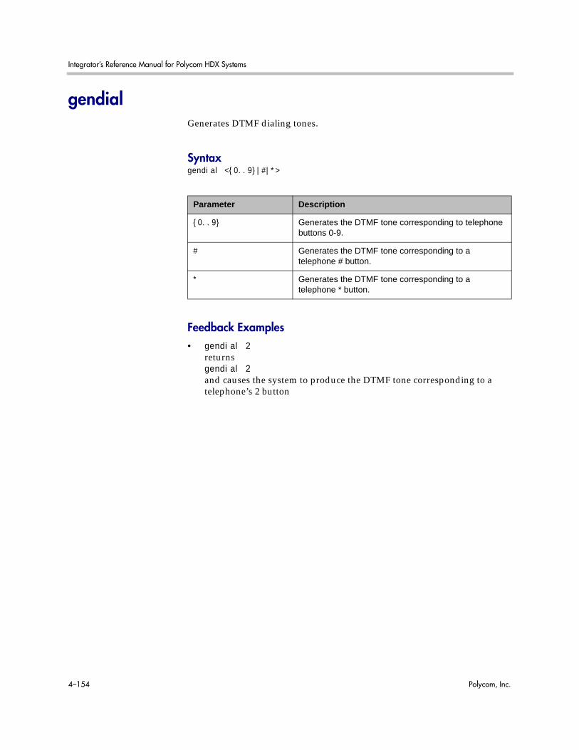
Integrator’s Reference Manual for Polycom HDX Systems
4–154 Polycom, Inc.
gendialGenerates DTMF dialing tones.
Syntaxgendial <{0..9}|#|*>
Feedback Examples• gendial 2
returnsgendial 2and causes the system to produce the DTMF tone corresponding to a telephone’s 2 button
Parameter Description
{0..9} Generates the DTMF tone corresponding to telephone buttons 0-9.
# Generates the DTMF tone corresponding to a telephone # button.
* Generates the DTMF tone corresponding to a telephone * button.
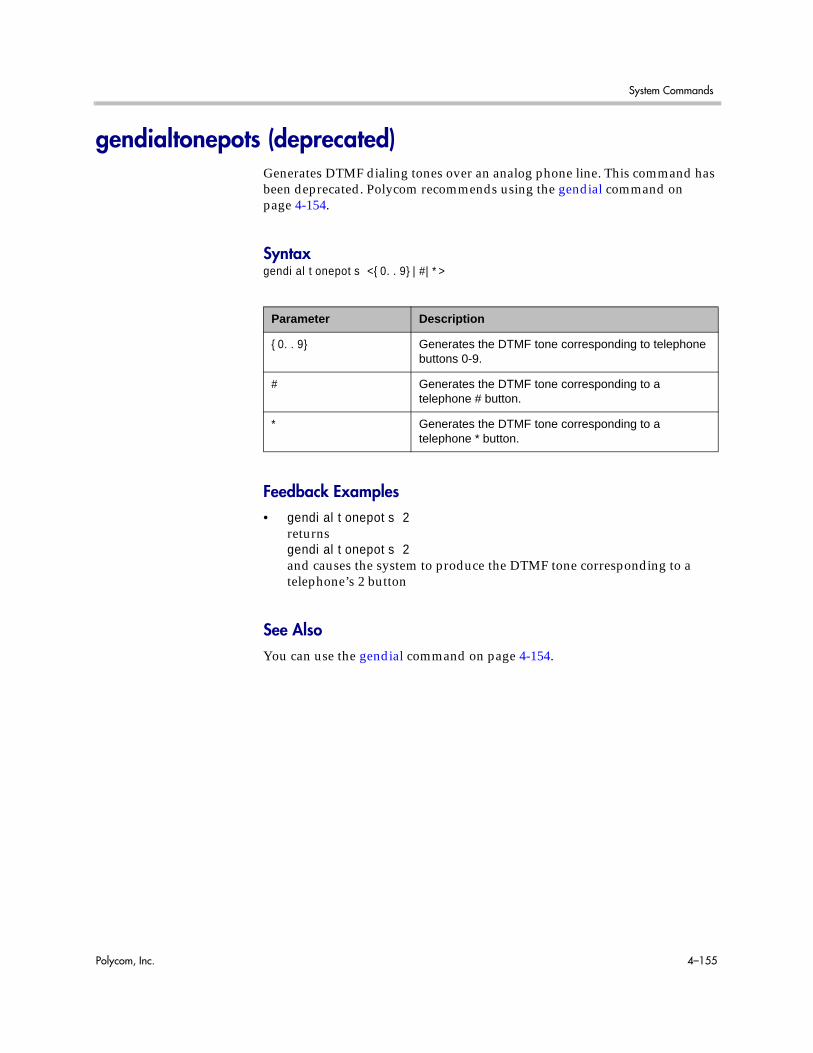
System Commands
Polycom, Inc. 4–155
gendialtonepots (deprecated)Generates DTMF dialing tones over an analog phone line. This command has been deprecated. Polycom recommends using the gendial command on page 4-154.
Syntaxgendialtonepots <{0..9}|#|*>
Feedback Examples• gendialtonepots 2
returnsgendialtonepots 2and causes the system to produce the DTMF tone corresponding to a telephone’s 2 button
See AlsoYou can use the gendial command on page 4-154.
Parameter Description
{0..9} Generates the DTMF tone corresponding to telephone buttons 0-9.
# Generates the DTMF tone corresponding to a telephone # button.
* Generates the DTMF tone corresponding to a telephone * button.

Integrator’s Reference Manual for Polycom HDX Systems
4–156 Polycom, Inc.
generatetoneTurns the test tone on or off. The tone is used to check the monitor audio cable connections or to monitor the volume level.
Syntaxgeneratetone <on|off>
Feedback Examples• generatetone on
returnsgeneratetone onand the system produces a test tone
• generatetone offreturnsgeneratetone offand the system stops producing a test tone
Parameter Description
on Turns on the test tone.
off Turns off the test tone.
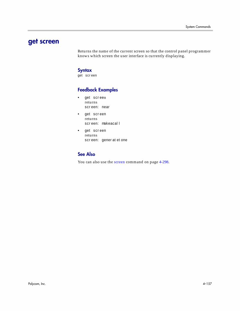
System Commands
Polycom, Inc. 4–157
get screenReturns the name of the current screen so that the control panel programmer knows which screen the user interface is currently displaying.
Syntaxget screen
Feedback Examples• get screen
returnsscreen: near
• get screenreturnsscreen: makeacall
• get screenreturnsscreen: generatetone
See AlsoYou can also use the screen command on page 4-298.

Integrator’s Reference Manual for Polycom HDX Systems
4–158 Polycom, Inc.
getcallstateGets the state of the calls in the current conference.
Syntaxgetcallstate
Feedback Examples• getcallstate
returnscs: call[34] speed[384] dialstr[192.168.1.101] state[connected]cs: call[1] inactivecs: call[2] inactive
See AlsoTo register the shell session to receive notifications about call state activities, see the callstate command on page 4-62.

System Commands
Polycom, Inc. 4–159
getconfiguredipaddressRetrieves the currently configured IPv4 address from the system.
Syntaxgetconfiguredipaddress
Feedback Examples• getconfiguredipaddress
returnsgetconfiguredipaddress 1.2.3.4
Commentsgetconfiguredipaddress returns the currently configured IPv4 address of the system regardless of the status of the LAN connection. This differs from the ipaddress get command, which returns the current IP address of the system if it has an active LAN connection, else it returns 0.0.0.0.
The definition of "currently configured IPv4 address” depends on the IPv4 address configuration settings:
• If the Connect to My LAN setting is disabled, then 0.0.0.0 is returned. Otherwise, the definition depends on the IP Address (IPv4) setting.
• If the IP address is set manually the configured IP address is returned, regardless of whether the LAN connection is currently active.
• If the IP address is obtained automatically, the currently-assigned address is returned, or 0.0.0.0 is returned if there is no active connection.

Integrator’s Reference Manual for Polycom HDX Systems
4–160 Polycom, Inc.
gmscitySets or gets the Polycom Global Management System™ city information.
Syntaxgmscity getgmscity set [“city”]
Feedback Examples• gmscity get
returnsgmscity <empty>
• gmscity set Parisreturnsgmscity Paris
• gmscity getreturnsgmscity Paris
Parameter Description
get Returns the current setting.
set Sets the Global Management System city name when followed by the “city” parameter. To erase the current setting, omit “city”.
“city” Character string specifying the city. Enclose the string in quotation marks if it includes spaces. Example: “San Antonio”

System Commands
Polycom, Inc. 4–161
gmscontactemailSets or gets the Global Management System contact email information.
Syntaxgmscontactemail getgmscontactemail set [“email”]
Feedback Examples• gmscontactemail get
returnsgmscontactemail <empty>
• gmscontactemail set [email protected] [email protected]
• gmscontactemail getreturnsgmscontactemail [email protected]
Parameter Description
get Returns the current contact email address.
set Sets the Global Management system contact email address when followed by the “email” parameter. To erase the current setting, omit “email”.
“email” Alphanumeric string specifying the email address.
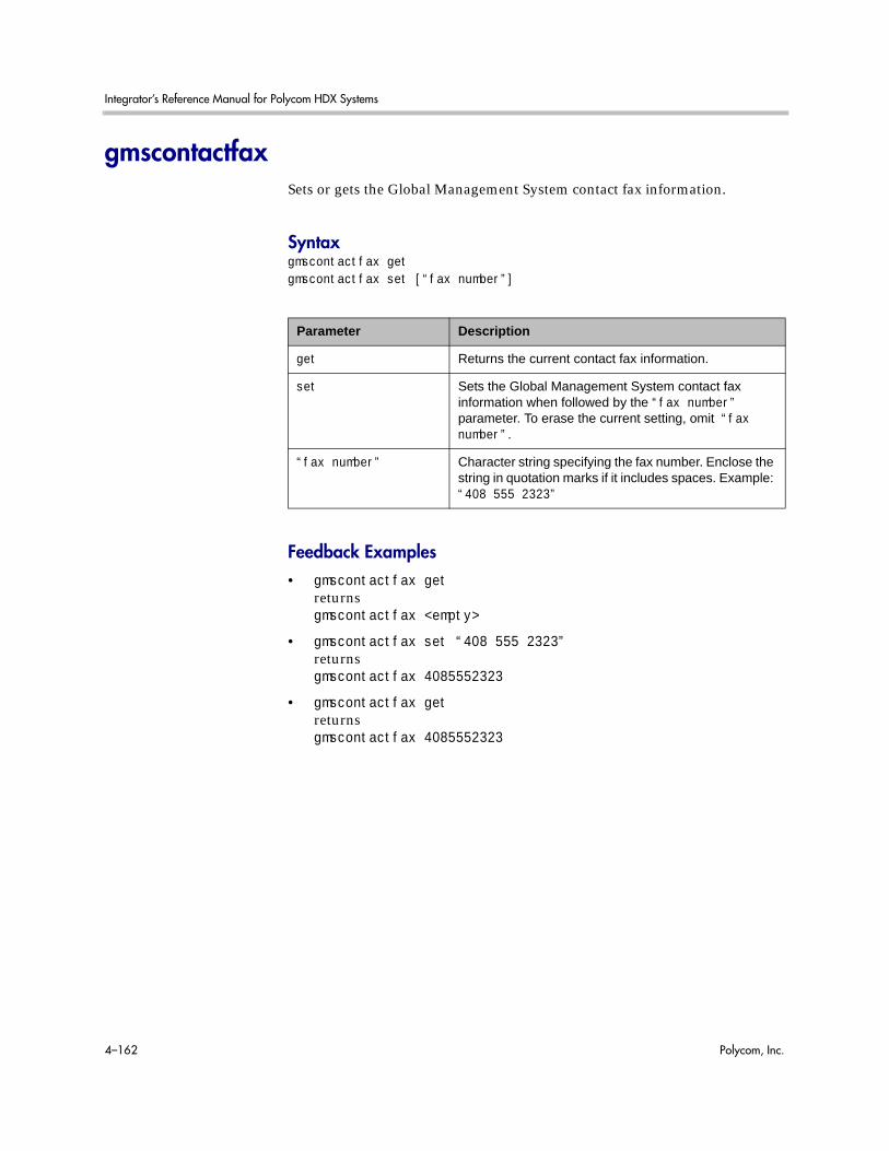
Integrator’s Reference Manual for Polycom HDX Systems
4–162 Polycom, Inc.
gmscontactfaxSets or gets the Global Management System contact fax information.
Syntaxgmscontactfax getgmscontactfax set [“fax number”]
Feedback Examples• gmscontactfax get
returnsgmscontactfax <empty>
• gmscontactfax set “408 555 2323”returnsgmscontactfax 4085552323
• gmscontactfax getreturnsgmscontactfax 4085552323
Parameter Description
get Returns the current contact fax information.
set Sets the Global Management System contact fax information when followed by the “fax number” parameter. To erase the current setting, omit “fax number”.
“fax number” Character string specifying the fax number. Enclose the string in quotation marks if it includes spaces. Example: “408 555 2323”

System Commands
Polycom, Inc. 4–163
gmscontactnumberSets or gets the Global Management System contact number information.
Syntaxgmscontactnumber getgmscontactnumber set [“number”]
Feedback Examples• gmscontactnumber get
returnsgmscontactnumber <empty>
• gmscontactnumber set “408 555 2323”returnsgmscontactnumber 4085552323
• gmscontactnumber getreturnsgmscontactnumber 4085552323
Parameter Description
get Returns the current contact number.
set Sets the Global Management System contact number when followed by the “number” parameter. To erase the current setting, omit “number”.
“number” Numeric string specifying the contact number. Enclose the string in quotation marks if it includes spaces. Example: “408 555 2323”

Integrator’s Reference Manual for Polycom HDX Systems
4–164 Polycom, Inc.
gmscontactpersonSets or gets the Global Management System contact person information.
Syntaxgmscontactperson getgmscontactperson set [“person”]
Feedback Examples• gmscontactperson get
returnsgmscontactperson <empty>
• gmscontactperson set “Mary Polycom”returnsgmscontactperson “Mary Polycom”
• gmscontactperson getreturnsgmscontactnumber “Mary Polycom”
Parameter Description
get Returns the current contact person information.
set Sets the Global Management System contact person name when followed by the “person” parameter. To erase the current setting, omit “person”.
“person” Character string specifying the contact person. Enclose the string in quotation marks if it includes spaces. Example: “Mary Polycom”

System Commands
Polycom, Inc. 4–165
gmscountrySets or gets the Global Management System country information.
Syntaxgmscountry getgmscountry set [“countryname”]
Feedback Examples• gmscountry get
returnsgmscountry <empty>
• gmscountry set Argentinareturnsgmscountry Argentina
• gmscountry getreturnsgmscountry Argentina
Parameter Description
get Returns the current country setting.
set Sets the Global Management System country information when followed by the “countryname” parameter. To erase the current setting, omit “countryname”.
“countryname” Character string specifying the country. Enclose the string in quotation marks if it includes spaces. Example: “United States”

Integrator’s Reference Manual for Polycom HDX Systems
4–166 Polycom, Inc.
gmsstateSets or gets the Global Management System state information.
Syntaxgmsstate getgmsstate set [“state”]
Feedback Examples• gmsstate get
returnsgmsstate <empty>
• gmsstate set Texasreturnsgmsstate Texas
• gmsstate getreturnsgmsstate Texas
Parameter Description
get Returns the current state information.
set Sets the Global Management System state information when followed by the “state” parameter. To erase the current setting, omit the “state” parameter.
“state” Character string specifying the state information. Enclose the string in quotation marks if it includes spaces. Example: “West Virginia”

System Commands
Polycom, Inc. 4–167
gmstechsupportSets or gets the Global Management System technical support phone number.
Syntaxgmstechsupport getgmstechsupport set [“tech_support_digits”]
Feedback Examples• gmstechsupport get
returnsgmstechsupport <empty>
• gmstechsupport set “408 555 2323”returnsgmstechsupport 4085552323
• gmstechsupport getreturnsgmstechsupport 4085552323
Parameter Description
get Returns the current tech support phone number information.
set Sets the technical support information when followed by the “tech_support_digits” parameter. To erase the current setting, omit “tech_support_digits”.
“tech_support_digits” Numeric string specifying the tech support phone number. Enclose the string in quotation marks if it includes spaces. Example: “408 555 2323”

Integrator’s Reference Manual for Polycom HDX Systems
4–168 Polycom, Inc.
gmsurlGets the URL of the Global Management System server that manages your system. This command automatically appends “/pwx/vs_status.asp”.
Syntaxgmsurl get {1..10}gmsurl get all
Feedback Examples• gmsurl get 1
returnsgmsurl 1 192.168.1.101/pwx/nx_status.asp
CommentsWhen you are registered with the Global Management System, this information is automatically configured.
Parameter Description
get Returns the current URL information for a selected server. A server must be specified.
{1..10} Global Management System server number. The primary Global Management System server that performs account validation is always server 1.
all Returns information for all Global Management System servers.
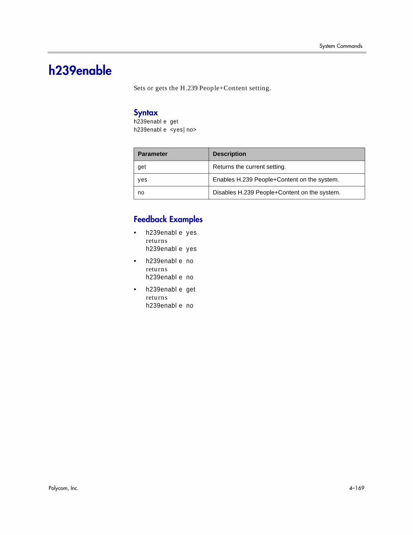
System Commands
Polycom, Inc. 4–169
h239enableSets or gets the H.239 People+Content setting.
Syntaxh239enable geth239enable <yes|no>
Feedback Examples• h239enable yes
returnsh239enable yes
• h239enable noreturnsh239enable no
• h239enable getreturnsh239enable no
Parameter Description
get Returns the current setting.
yes Enables H.239 People+Content on the system.
no Disables H.239 People+Content on the system.

Integrator’s Reference Manual for Polycom HDX Systems
4–170 Polycom, Inc.
h323nameSets or gets the system’s H.323 name.
Syntaxh323name geth323name set [“H.323name”]
Feedback Examples• h323name set My
returnsh323name my
• h323name set “Polycom HDX Demo”returnsh323name “polycom hdx demo”
• h323name getreturnsh323name “polycom hdx demo”
Parameter Description
get Returns the current setting.
set Sets the H.323 name when followed by the “H.323name” parameter. To erase this setting, omit the “H.323name” parameter.
“H.323name” Character string specifying the H.323 name. Use quotation marks around strings that contain spaces. For example: “Polycom HDX Demo”

System Commands
Polycom, Inc. 4–171
h331audiomodeSet or gets the audio protocol sent during H.331 calls. This command is only applicable if you have a V.35 network interface connected to your system.
Syntaxh331audiomode <get|g729|g728|g711u|g711a|g722-56|g722-48|g7221-16|g7221-24|g7221-32|siren14|siren14stereo|off>
Feedback Examples• h331audiomode g.728
returnsh331audiomode g.728
• h331audiomode “siren 14”returnsh331audiomode “siren 14”
• h331audiomode offreturnsh331audiomode off
CommentsThis value cannot be changed during a call.
Parameter Description
get Returns the current setting.
g729|g728|g711u|g711a|g722-56|g722-48|g7221-16|g7221-24|g7221-32|siren14|siren14stereo
Sets the audio protocol to this value for H.331 calls.
off Turns audio mode off for H.331 calls.

Integrator’s Reference Manual for Polycom HDX Systems
4–172 Polycom, Inc.
h331dualstreamSet or gets the dual stream setting used for H.331 calls. This command is only applicable if you have a V.35 network interface connected to your system.
Syntaxh331dualstream <get|on|off>
Feedback Examples• h331dualstream on
returnsh331dualstream on
• h331dualstream offreturnsh331dualstream off
• h331dualstream getreturnsh331dualstream off
CommentsThis value cannot be changed during a call.
Parameter Description
get Returns the current setting.
on Turns on dual stream for H.331 calls.
off Turns off dual stream for H.331 calls.

System Commands
Polycom, Inc. 4–173
h331framerateSets or gets the frame rate sent during H.331 calls. This command is only applicable if you have a V.35 network interface connected to your system.
Syntaxh331framerate <get|30|15|10|7.5>
Feedback Examples• h331framerate 15
returnsh331framerate 15
• h331framerate 30returnsh331framerate 30
• h331framerate getreturnsh331framerate 30
CommentsThis value cannot be changed during a call.
Parameter Description
get Returns the current setting.
30|15|10|7.5 Sets the frame rate to this value for H.331 calls.

Integrator’s Reference Manual for Polycom HDX Systems
4–174 Polycom, Inc.
h331videoformatSets or gets the video format for H.331 calls. This command is only applicable if you have a V.35 network interface connected to your system.
Syntaxh331videoformat <get|fcif>
Feedback Examples• h331videoformat fcif
returnsh331videoformat fcif
• h331videoformat getreturnsh331videoformat fcif
Parameter Description
get Returns the current setting.
fcif Sets the video format to FCIF for H.331 calls.

System Commands
Polycom, Inc. 4–175
h331videoprotocolSets or gets the H.331 video protocol sent during H.331 calls. This command is only applicable if you have a V.35 network interface connected to your system.
Syntaxh331videoprotocol <get|h264|h263+|h263|h261>
Feedback Examples• h331videoprotocol h264
returnsh331videoprotocol h264
• h331videoprotocol h263+returnsh331videoprotocol h263+
• h331videoprotocol getreturnsh331videoprotocol h263+
CommentsThis value cannot be changed during a call.
Parameter Description
get Returns the current setting.
h264|h263+|h263|h261 Sets the video protocol to this value for H.331 calls.

Integrator’s Reference Manual for Polycom HDX Systems
4–176 Polycom, Inc.
hangupHangs up the current video or phone call.
Syntaxhangup phonehangup video [“callid”]hangup all
Feedback Examples• hangup video
returnshanging up video
• hangup video 42returnshanging up videoand disconnects the specified site, leaving other sites connected
• If callstate register is used for notifications,hangup video 42returnshanging up videocleared: call[42]dialstring[IP:192.168.1.101 NAME:Polycom HDX Demo]ended: call[42]and disconnects the specified site, leaving other sites connected
CommentsAfter sending the hangup command, feedback that the call has ended can take up to 15 seconds.
Parameter Description
phone Disconnects the current analog phone (audio-only) site.
video Disconnects the current video call. If the “callid” parameter is omitted, the system disconnects all video far sites in the call.
all Disconnects all video and audio sites in the call.

System Commands
Polycom, Inc. 4–177
historyLists the last commands used in the current session.
Syntaxhistory
Feedback Examples• history
returns1 ipaddress set 192.168.1.1012 hostname set My3 lanport 100fdx4 callstate register5 lanport get6 history
CommentsIf more than 64 commands have been issued, only the last 64 are displayed, with the most recent always at the bottom.

Integrator’s Reference Manual for Polycom HDX Systems
4–178 Polycom, Inc.
homecallqualitySets or gets whether users are allowed to select the bandwidth for calls from the Place a Call screen.
Syntaxhomecallquality <get|yes|no>
Feedback Examples• homecallquality yes
returnshomecallquality yes
• homecallquality noreturnshomecallquality no
• homecallquality getreturnshomecallquality no
Parameter Description
get Returns the current setting.
yes Displays the Call Quality menu on the home Place a Call screen.
no Removes the Call Quality menu from the Place a Call screen.

System Commands
Polycom, Inc. 4–179
homemultipoint (deprecated)Sets or gets whether users are allowed to access the multipoint dialing screen via a Multipoint button on the home screen. This command has been deprecated.
Syntaxhomemultipoint <get|yes|no>
Feedback Examples• homemultipoint yes
returnshomemultipoint yes
• homemultipoint noreturnshomemultipoint no
• homemultipoint getreturnshomemultipoint no
CommentsThis option is only available if multipoint calling is enabled.
Parameter Description
get Returns the current setting.
yes Displays the Multipoint button on the Home screen.
no Removes the Multipoint button from the Home screen.

Integrator’s Reference Manual for Polycom HDX Systems
4–180 Polycom, Inc.
homerecentcallsSets or gets whether users are allowed to access a list of recent calls made with the system by displaying the Recent Calls button on the Home screen.
Syntaxhomerecentcalls <get|yes|no>
Feedback Examples• homerecentcalls yes
returnshomerecentcalls yes
• homerecentcalls noreturnshomerecentcalls no
• homerecentcalls getreturnshomerecentcalls no
CommentsThis option is only available if the Call Detail Report option is enabled.
Parameter Description
get Returns the current setting.
yes Displays the Recent Calls button on the Home screen.
no Removes the Recent Calls button from the Home screen.

System Commands
Polycom, Inc. 4–181
homesystemSets or gets whether users are allowed to access the System screen by displaying the System button on the Home screen.
Syntaxhomesystem <get|yes|no>
Feedback Examples• homesystem yes
returnshomesystem yes
• homesystem noreturnshomesystem no
• homesystem getreturnshomesystem no
Parameter Description
get Returns the current setting.
yes Displays the System button on the Home screen.
no Removes the System button from the Home screen.

Integrator’s Reference Manual for Polycom HDX Systems
4–182 Polycom, Inc.
homesystemnameSets or gets whether to display the name of the system on the Home screen, above the PIP window.
Syntaxhomesystemname <get|yes|no>
Feedback Examples• homesystemname yes
returnshomesystemname yes
• homesystemname noreturnshomesystemname no
• homesystemname getreturnshomesystemname no
Parameter Description
get Returns the current setting.
yes Displays the system name on the Home screen.
no Removes the system name from the Home screen.

System Commands
Polycom, Inc. 4–183
hostnameSets or gets the LAN host name, which is assigned to the system for TCP/IP configuration and can be used in place of an IP address when dialing IP calls.
Syntaxhostname gethostname set [“hostname”]
Feedback Examples• hostname set
returnshostname ADMINrestart system for changes to take effect. restart now? <y,n>
• hostname set “My”returnshostname Myrestart system for changes to take effect. restart now? <y,n>
• hostname getreturnshostname My
Parameter Description
get Returns the current setting.
set Sets the system’s LAN host name when followed by the “hostname” parameter. If “hostname” is omitted, the system automatically sets it to Admin.
“hostname” Character string specifying the LAN host name of the system. The LAN host name follows these format rules:
Starts with a letter (A-a to Z-z). It is not case sensitive.
Ends with a letter (A-a to Z-z) or a number (0 to 9).
May include letters, numbers, and a hyphen.
May not be longer than 63 characters.
Note: The LAN host name is initialized during the out-of-box setup sequence. The LAN host name is the same as the system name, if the system name conforms to the rules above. If the system name does not conform to these rules, the invalid characters are removed from the system name. If the resulting string is empty, the default LAN host name is Admin.

Integrator’s Reference Manual for Polycom HDX Systems
4–184 Polycom, Inc.
CommentsA LAN host name is required; it cannot be deleted or left blank. After making a change, you must restart the system for the setting to take effect.

System Commands
Polycom, Inc. 4–185
icmpoutpacketrateSpecify minimum number of milliseconds between packets to limit the ICMP packet transmission rate.
Syntaxicmpoutpacketrate geticmpoutpacketrate set {0..60000}
Feedback Examples• icmpoutpacketrate get
returnsicmpoutpacketrate 1000
• icmpoutpacketrate set 1001returnsicmpoutpacketrate 1001
CommentsApplicable for both IPv4 and IPv6 configurations. When 0 is specified, the ICMP packet transmission rate limit is turned off.
After making a change, you must restart the system for the setting to take effect.
See Also destunreachabletx on page 4-93.
Parameter Description
get Returns the minimum number of milliseconds between transmitted ICMP packets.
set Sets the minimum number of milliseconds between transmitted ICMP packets.
{0..60000} The packet rate. This must be an integer in the range {0..60000}.
1000=1 packet per second.

Integrator’s Reference Manual for Polycom HDX Systems
4–186 Polycom, Inc.
ignoreredirectSets or gets the ability of the system to redirect messages, which may come from a router as part of the IPv6 Neighbor Discovery protocol.
Syntaxignoreredirect getignoreredirect <yes | no>
Feedback Examples• ignoreredirect get
returnsignoreredirect no
• ignoreredirect set yesreturnsignoreredirect yes
CommentsThis setting is applicable for both IPv4 and IPv6 configurations.
After making a change, you must restart the system for the setting to take effect.
Parameter Description
get Returns the current IPv6 ignore redirect setting.
yes Enables the IPv6 ignore redirect setting.
no Disables the IPv6 ignore redirect setting.

System Commands
Polycom, Inc. 4–187
importdirectoryImports a directory in CSV or XML format
Syntaximportdirectory<import data line 1><import data line 2><import data line 3>...importcomplete
Feedback Examples• importdirectory
<?xml version="1.0" encoding="UTF-8" ?><addresses><entrytype type="entry" name="Polycom Austin USA IP" filename="Polycom_Austin_USA_IP.abk" uniqueid="Polycom_Austin_USA_IP.abk"><address filename="Polycom_Austin_USA_IP.abk" langid="" displayname="" name="Polycom Austin USA IP"><h323 address="lobby.austin.polycom.com" speed="256"/></address></entrytype><entrytype type="entry" name="Polycom Hong Kong" filename="Polycom_Hong_Kong.abk" uniqueid="Polycom_Hong_Kong.abk"><address filename="Polycom_Hong_Kong.abk" langid="" displayname="" name="Polycom Hong Kong"><isdn country_code="852" area_code="2876" numberA="9466" numberB="9466" speed="2x64"/></address> </addresses></xml>importcompletereturnsimportdirectory succeeded
• importdirectoryA,B,C,D,E,F,G,H,I,J,K,L,M,N,O,P,Q,R,S,T,U,V,W,X,Y,Z,AA,AB,AC,AD,AE,AF,AG,AH,AI,AJ,AK,AL,AM,AN,AO,AP,AQ,AR,AS,AT,AU,AV,AW,AX,AY,AZ,BA,BB,BC,BD,BE,BF,BG,BH,BI,BJ,BK,BL,BM,BN,BO,BP,BQ,BR,BS,BT,BU,BV,BW,BX,BY,BZ,CA,CB
File Name,Entry Name,ISDN Country Code,ISDN Area Code,ISDN

Integrator’s Reference Manual for Polycom HDX Systems
4–188 Polycom, Inc.
NumberA,ISDN NumberB,ISDN Extension,ISDN Speed,IP Address,IP Extension,IP Speed,Phone Country Code,Phone Area Code,Phone Number,Mobile Country Code,Mobile Area Code,Mobile Number,Email,Category,Meeting Name,Meeting Speed,Site Name 1,Call Type 1,Pref Number 1,Site Type 1,Site Name 2,Call Type 2,Pref Number 2,Site Type 2,Site Name 3,Call Type 3,Pref Number 3,Site Type 3,Site Name 4,Call Type 4,Pref Number 4,Site Type 4,Site Name 5,Call Type 5,Pref Number 5,Site Type 5,Site Name 6,Call Type 6,Pref Number 6,Site Type 6,Site Name 7,Call Type 7,Pref Number 7,Site Type 7,Site Name 8,Call Type 8,Pref Number 8,Site Type 8,Site Name 9,Call Type 9,Pref Number 9,Site Type 9,Site Unique Id 1,Site Server Address 1,Site Unique Id 2,Site Server Address 2,Site Unique Id 3,Site Server Address 3,Site Unique Id 4,Site Server Address 4,Site Unique Id 5,Site Server Address 5,Site Unique Id 6,Site Server Address 6,Site Unique Id 7,Site Server Address 7,Site Unique Id 8,Site Server Address 8,Site Unique Id 9,Site Server Address 9,Unique Id,Entry Type,Language Id,Display Name,
"Loopback_1.abk","Loopback 1",1,700,9581108,9581108,---,2x64,---,---,---,---,---,---,---,---,---,---,"Polycom_Test",---,---,---,---,---,---,---,---,---,---,---,---,---,---,---,---,---,---,---,---,---,---,---,---,---,---,---,---,---,---,---,---,---,---,---,---,---,---,---,---,---,---,---,---,---,---,---,---,---,---,---,---,---,---,---,---,Loopback_1.abk,2,---,"Loopback 1",
"Loopback_2.abk","Loopback 2",1,700,7308982,7308982,---,2x64,---,---,---,---,---,---,---,---,---,---,"Polycom_Test",---,---,---,---,---,---,---,---,---,---,---,---,---,---,---,---,---,---,---,---,---,---,---,---,---,---,---,---,---,---,---,---,---,---,---,---,---,---,---,---,---,---,---,---,---,---,---,---,---,---,---,---,---,---,---,---,Loopback_2.abk,2,---,"Loopback 2",
"Polycom_Austin_HD.abk","Polycom Austin HD",1,512,5148814,---,---,1024,hd.polycom.com,---,1024,---,---,---,---,---,---,---,"Polycom_Test",---,---,---,---,---,---,---,---,---,---,---,---,---,---,---,---,---,---,---,---,---,---,---,---,---,---,---,---,---,---,---,---,---,---,---,---,---,---,---,---,---,---,---,---,---,---,---,---,---,---,---,---,---,---,---,---,Polycom_Austin_HD.abk,2,---,"Polycom Austin HD",importcompletereturnsimportdirectory succeeded

System Commands
Polycom, Inc. 4–189
CommentsWhen importing XML-formatted data, the imported data must be in the same format as was obtained from the Polycom HDX system via the exportdirectory command on page 4-129 or the export directory utility in the web interface.
Duplicate entries are overwritten; other entries in the imported directory are added into the system's local directory.
All of the lines entered into the session after importdirectory is issued are interpreted as directory data.
Issuing the importcomplete command on its own line indicates that the directory import is complete.
If no data is received for 60 seconds during import, the import ends, and an "importdirectory timed out" error response is sent to the API session. All previous data entered is ignored.
Additional usage notes:
• Polycom HDX systems running software version 2.6 or later can import directory data exported from systems running version 2.6 and earlier versions.
• Polycom HDX systems running software versions earlier than 2.6 cannot import directory data exported by systems running software version 2.6 or later.
See AlsoSee the exportdirectory command on page 4-129.

Integrator’s Reference Manual for Polycom HDX Systems
4–190 Polycom, Inc.
importprofileImports system and user profile information in a CSV format. The input is submitted through the telnet or serial port.
Syntaximportprofile<import data line 1><import data line 2><import data line 3>. . .importcomplete
Feedback Examplesimportprofileh323name,s8whdaccelerator,BrutusTavayaenabled,""systemsoftwareversion_prev,2.6.0ipmaxincoming,4096speakervolume,25sysname,s8wspeedstranslated,Auto~128~256~384~512~768~1024~1472~1920~4096directoryinfoupdated,Truepwcreatetimeminremoteuser0,0. ..buildmodel,ROOSEVELThomebutton,MAKEACALLdialnumberext,""mp8enabled,""lastloginfromadmin,Localtimezone,CSTpresence,AVAILABLEprofilechecksum,16813327827importcomplete
importprofile succeeded
CommentsWhen importing profile data, the imported data must be in the same format as was obtained from the Polycom HDX system via the exportprofile command on page 4-131 or the export profile utility in the web interface. When

System Commands
Polycom, Inc. 4–191
importing profile data back into the system, use the data in its entirety (not edited in any form). The system may use the checksum utility to verify of integrity of the data when imported back into the system.
importprofile succeeded is returned to indicate that the profile data has been imported.
A reboot of the system is required after successfully importing system and user profile information and will occur automatically after the import is complete.
See AlsoSee the exportprofile command on page 4-131.

Integrator’s Reference Manual for Polycom HDX Systems
4–192 Polycom, Inc.
incompleterevocationcheckSets or gets the ability to use or reject a certificate if revocation checking is incomplete.
Syntaxincompleterevocationcheck getincompleterevocationcheck set <yes|no>
Feedback Examples• incompleterevocationcheck get
returnsincompleterevocationcheck yes
• incompleterevocationcheck set yesreturnsincompleterevocationcheck yes
• incompleterevocationcheck set noreturnsincompleterevocationcheck no
CommentsAfter making a change, you must restart the system for the setting to take effect.
Parameter Description
get Returns the current setting.
set Sets the certificate validation setting.
yes Allows the system to continue to use a certificate in some cases if revocation checking is incomplete.
no Rejects a certificate with incomplete revocation checking.

System Commands
Polycom, Inc. 4–193
ipaddressSets or gets the LAN IP address (IPv4) of the system.
Syntaxipaddress getipaddress set “xxx.xxx.xxx.xxx”
Feedback Examples• ipaddress set 192.168.1.101
returnsipaddress 192.168.1.101
• ipaddress get returnsipaddress 192.168.1.101
CommentsUse this command when you need to allocate a static IP address to your system. After making a change, you must restart the system for the setting to take effect.
Parameter Description
get Returns the current setting.
set Sets the LAN IP address to the “xxx.xxx.xxx.xxx” parameter. This setting can only be changed when DHCP is off.
“xxx.xxx.xxx.xxx” IP address of the system.
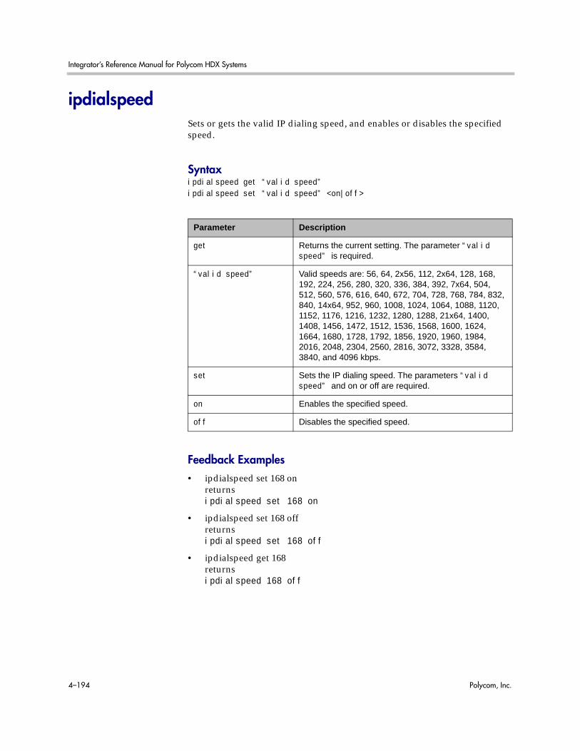
Integrator’s Reference Manual for Polycom HDX Systems
4–194 Polycom, Inc.
ipdialspeedSets or gets the valid IP dialing speed, and enables or disables the specified speed.
Syntaxipdialspeed get “valid speed”ipdialspeed set “valid speed” <on|off>
Feedback Examples• ipdialspeed set 168 on
returnsipdialspeed set 168 on
• ipdialspeed set 168 offreturnsipdialspeed set 168 off
• ipdialspeed get 168returnsipdialspeed 168 off
Parameter Description
get Returns the current setting. The parameter “valid speed” is required.
“valid speed” Valid speeds are: 56, 64, 2x56, 112, 2x64, 128, 168, 192, 224, 256, 280, 320, 336, 384, 392, 7x64, 504, 512, 560, 576, 616, 640, 672, 704, 728, 768, 784, 832, 840, 14x64, 952, 960, 1008, 1024, 1064, 1088, 1120, 1152, 1176, 1216, 1232, 1280, 1288, 21x64, 1400, 1408, 1456, 1472, 1512, 1536, 1568, 1600, 1624, 1664, 1680, 1728, 1792, 1856, 1920, 1960, 1984, 2016, 2048, 2304, 2560, 2816, 3072, 3328, 3584, 3840, and 4096 kbps.
set Sets the IP dialing speed. The parameters “valid speed” and on or off are required.
on Enables the specified speed.
off Disables the specified speed.

System Commands
Polycom, Inc. 4–195
CommentsThe Polycom HDX system does not support separate settings for IP and ISDN dialing speeds.When you change a setting using this command, the settings associated with the isdndialspeed command on page 4-207 also change, and vice versa.

Integrator’s Reference Manual for Polycom HDX Systems
4–196 Polycom, Inc.
ipisdninfoSets or gets whether the Home screen displays IP information, ISDN information, both, or neither.
Syntaxipisdninfo <get|both|ip-only|isdn-only|none>
Feedback Examples• ipisdninfo ip-only
returnsipisdninfo ip-only
• ipisdninfo bothreturnsipisdninfo both
• ipisdninfo getreturnsipisdninfo both
Parameter Description
get Returns the current setting.
both Displays IP and ISDN information on the Home screen.
ip-only Displays only IP information on the Home screen.
isdn-only Displays only ISDN information on the Home screen.
none Does not display any IP or ISDN information on the Home screen.

System Commands
Polycom, Inc. 4–197
ipprecaudio, ipprecfecc, ipprecvideoSets or gets the IP Precedence priority level (Type of Service Value) for audio, far-end camera control (FECC) and other call control channels, and video. The value for each can be between 0 and 7.
Syntaxipprecaudio getipprecaudio set {0..7}ipprecfecc getipprecfecc set {0..7}ipprecvideo getipprecvideo set {0..7}
Feedback Examples• ipprecaudio set 5
returnsipprecaudio 5
• ipprecaudio getreturnsipprecaudio 5
CommentsThe ipprecfecc command is equivalent to the Control setting in the user interface.
If the typeofservice command on page 4-331 is set to diffserv, these commands are not applicable.
Parameter Description
get Returns the current setting.
set Sets the IP precedence. A priority level is required. This must be an integer in the range {0..7}.

Integrator’s Reference Manual for Polycom HDX Systems
4–198 Polycom, Inc.
ipv6addrmodeSets or gets the ability for the system to act as a client and receive an address, specify an address manually, or completely disable IPv6.
Syntaxipv6addrmode <get|client|manual|off>
Feedback Examples• ipv6addrmode get
returnsipv6addrmode client
• ipv6addrmode offreturnsipv6globaladdress off
CommentsThis setting is applicable for both IPv4 and IPv6 configurations.
After making a change, you must restart the system for the setting to take effect.
Parameter Description
get Returns the current setting.
client IPv6 addresses from network elements.
manual Allows full configuration of IPv6 addresses.
off Disables IPv6 addressing.

System Commands
Polycom, Inc. 4–199
ipv6globaladdressSets or gets the IPv6 link global address.
Syntaxipv6globaladdress getipv6globaladdress set “ipv6 global address”
Feedback Examples• ipv6globaladdress get
returnsipv6globaladdress 2002:ac1a:140:0:2e0:dbff:fe08:a03a/64
• ipv6globaladdress set 2002:ac1a:140:0:2e0:dbff:fe08:a03a/64returnsipv6globaladdress 2002:ac1a:140:0:2e0:dbff:fe08:a03a/64
CommentsAfter making a change, you must restart the system for the setting to take effect. This setting can be changed only when ipv6addrmode is set to manual.
See Alsoipv6addrmode on page 4-198
Parameter Description
get Returns the current setting.
set Sets the IPv6 global address.
ipv6 link global address
The local IPv6 global address.

Integrator’s Reference Manual for Polycom HDX Systems
4–200 Polycom, Inc.
ipv6defaultgatewaySets or gets the IPv6 default gateway.
Syntaxipv6defaultgateway getipv6defaultgateway set “ipv6 link local address”
Feedback Examples• ipv6defaultgateway get
returnsipv6defaultgateway fe80::213:5fff:fe2f:2e4a
• ipv6defaultgateway set fe80::213:5fff:fe2f:2e4areturnsipv6defaultgateway fe80::213:5fff:fe2f:2e4a
CommentsAfter making a change, you must restart the system for the setting to take effect. This setting can be changed only when ipv6addrmode is set to manual.
See Alsoipv6addrmode on page 4-198
Parameter Description
get Returns the current setting.
set Sets the IPv6 default gateway.
ipv6 default gateway The local IPv6 default gateway.

System Commands
Polycom, Inc. 4–201
ipv6linklocalSets or gets the IPv6 link local address.
Syntaxipv6linklocal getipv6linklocal set “ipv6 link local address”
Feedback Examples• ipv6linklocal get
returnsipv6linklocal fe80::2e0:dbff:fe08:a03a/64
• ipv6linklocal set fe80::2e0:dbff:fe08:a03a/64returnsipv6linklocal fe80::2e0:dbff:fe08:a03a/64
CommentsAfter making a change, you must restart the system for the setting to take effect. This setting can be changed only when ipv6addrmode is set to manual.
See Alsoipv6addrmode on page 4-198
Parameter Description
get Returns the current setting.
set Sets the IPv6 link local address.
ipv6 link local address
The local IPv6 link local address.

Integrator’s Reference Manual for Polycom HDX Systems
4–202 Polycom, Inc.
ipv6sitelocalSets or gets the IPv6 site local address.
Syntaxipv6sitelocal getipv6sitelocal set “ipv6 site local address”
Feedback Examples• ipv6sitelocal get
returnsipv6sitelocal fed0:0:140:1:2e0:dbff:fe08:a03a/64
• ipv6sitelocal set fed0:0:140:1:2e0:dbff:fe08:a03a/64returnsipv6sitelocal fed0:0:140:1:2e0:dbff:fe08:a03a/64
CommentsAfter making a change, you must restart the system for the setting to take effect. This setting can be changed only when ipv6addrmode is set to manual.
See Alsoipv6addrmode on page 4-198.
Parameter Description
get Returns the current setting.
set Sets the IPv6 site local address.
ipv6 site local address
The local IPv6 site local address.
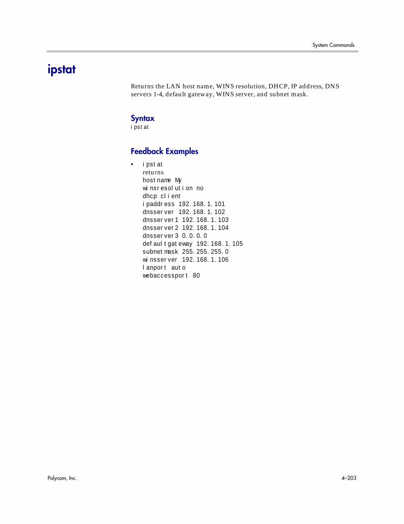
System Commands
Polycom, Inc. 4–203
ipstatReturns the LAN host name, WINS resolution, DHCP, IP address, DNS servers 1-4, default gateway, WINS server, and subnet mask.
Syntaxipstat
Feedback Examples• ipstat
returnshostname Mywinsresolution nodhcp clientipaddress 192.168.1.101dnsserver 192.168.1.102dnsserver1 192.168.1.103dnsserver2 192.168.1.104dnsserver3 0.0.0.0defaultgateway 192.168.1.105subnetmask 255.255.255.0winsserver 192.168.1.106lanport autowebaccessport 80

Integrator’s Reference Manual for Polycom HDX Systems
4–204 Polycom, Inc.
isdnareacodeSets or gets the ISDN area code or STD code associated with the area where the system is used. This command is only applicable if you have an ISDN network interface connected to your system.
Syntaxisdnareacode getisdnareacode set ["area code"]
Feedback Examples• isdnareacode set 700
returnsisdnareacode 700
• isdnareacode getreturnsisdnareacode 700
Parameter Description
get Returns the area code information.
set Sets the ISDN area code when followed by the “area code” parameter. To erase the current setting, omit “area code”.
“area code” Numeric value.

System Commands
Polycom, Inc. 4–205
isdncountrycodeSets or gets the ISDN country code associated with the country where the system is used. This command is only applicable if you have an ISDN network interface connected to your system.
Syntaxisdncountrycode getisdncountrycode set [“country code”]
Feedback Examples• isdncountrycode set 1
returnsisdncountrycode 1
• isdncountrycode getreturnsisdncountrycode 1
CommentsThe system is generally able to automatically determine the country code based on the country you selected during initial system setup.
Parameter Description
get Returns the country code information.
set Sets the ISDN country code when followed by the “country code” parameter. To erase the current setting, omit “country code”.
“country code” The ISDN country code.

Integrator’s Reference Manual for Polycom HDX Systems
4–206 Polycom, Inc.
isdndialingprefixSets or gets the ISDN dialing prefix used to access an outside line if the system is behind a PBX. This command is only applicable if you have an ISDN network interface connected to your system.
Syntaxisdndialingprefix getisdndialingprefix set [“isdn prefix”]
Feedback Examples• isdndialingprefix set 9
returnsisdndialingprefix 9
• isdndialingprefix getreturnsisdndialingprefix 9
Parameter Description
get Returns the dialing prefix.
set Sets the ISDN prefix when followed by the “isdn prefix” parameter. To erase the current setting, omit “isdn prefix”.
“isdn prefix” The digit(s) that must be dialed to reach an outside line.
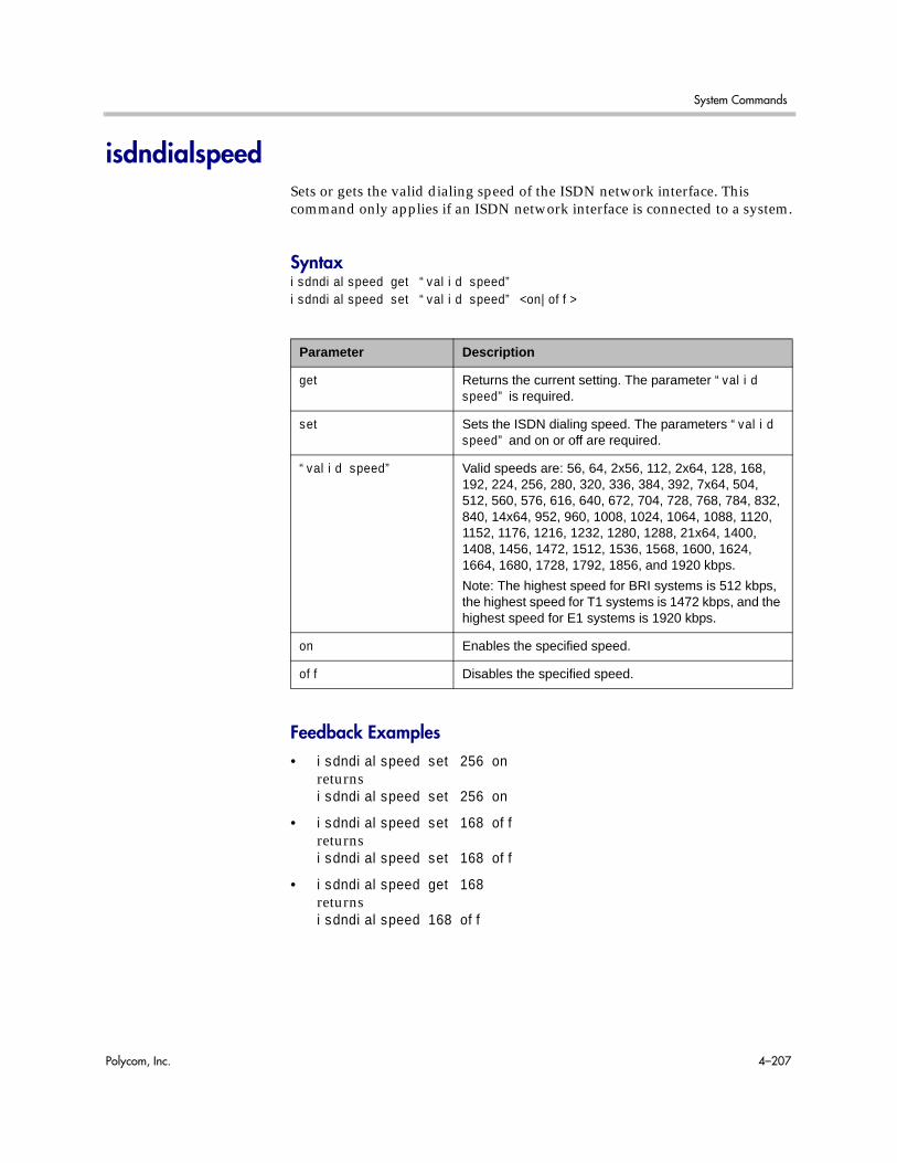
System Commands
Polycom, Inc. 4–207
isdndialspeedSets or gets the valid dialing speed of the ISDN network interface. This command only applies if an ISDN network interface is connected to a system.
Syntaxisdndialspeed get “valid speed”isdndialspeed set “valid speed” <on|off>
Feedback Examples• isdndialspeed set 256 on
returnsisdndialspeed set 256 on
• isdndialspeed set 168 offreturnsisdndialspeed set 168 off
• isdndialspeed get 168returnsisdndialspeed 168 off
Parameter Description
get Returns the current setting. The parameter “valid speed” is required.
set Sets the ISDN dialing speed. The parameters “valid speed” and on or off are required.
“valid speed” Valid speeds are: 56, 64, 2x56, 112, 2x64, 128, 168, 192, 224, 256, 280, 320, 336, 384, 392, 7x64, 504, 512, 560, 576, 616, 640, 672, 704, 728, 768, 784, 832, 840, 14x64, 952, 960, 1008, 1024, 1064, 1088, 1120, 1152, 1176, 1216, 1232, 1280, 1288, 21x64, 1400, 1408, 1456, 1472, 1512, 1536, 1568, 1600, 1624, 1664, 1680, 1728, 1792, 1856, and 1920 kbps.
Note: The highest speed for BRI systems is 512 kbps, the highest speed for T1 systems is 1472 kbps, and the highest speed for E1 systems is 1920 kbps.
on Enables the specified speed.
off Disables the specified speed.

Integrator’s Reference Manual for Polycom HDX Systems
4–208 Polycom, Inc.
CommentsThe Polycom HDX system does not support separate settings for ISDN and IP dialing speeds.When you change a setting using this command, the settings associated with the ipdialspeed command on page 4-194 also change, and vice versa.

System Commands
Polycom, Inc. 4–209
isdnnumSets or gets the ISDN video number or numbers assigned to the system. This command is only applicable if you have an ISDN network interface connected to your system.
Syntaxisdnnum get <1b1|1b2|2b1|2b2|3b1|3b2|4b1|4b2>isdnnum set <1b1|1b2|2b1|2b2|3b1|3b2|4b1|4b2> [“number”]
Feedback Examples• isdnnum set 1b1 “700 555 1212”
returnsisdnnum 1b1 7005551212
• isdnnum get 1b1returnsisdnnum 1b1 7005551212
CommentsThe isdnnum set 1b1 and isdnnum get 1b1 commands can be used for BRI and for PRI lines.
Parameter Description
get Returns the current ISDN number associated with the specified B channel.
set Sets the ISDN number for a B channel line when followed by the “number” parameter. To erase the current setting, omit “number”. This paramater is not allowed while in a call.
1b1|1b2|2b1|2b2|3b1|3b2|4b1|4b2
The line and B channel. Valid values are:
1b1BRI line 1, B channel 1
1b2BRI line 1, B channel 2
2b1BRI line 2, B channel 1
2b2BRI line 2, B channel 2
3b1BRI line 3, B channel 1
3b2BRI line 3, B channel 2
4b1BRI line 4, B channel 1
4b2BRI line 4, B channel 2
“number” The ISDN number(s) provided by your network service provider for the specified B channel.

Integrator’s Reference Manual for Polycom HDX Systems
4–210 Polycom, Inc.
isdnswitchSets or gets the ISDN switch protocol. This command is only applicable if you have an ISDN network interface connected to your system.
Syntaxisdnswitch getisdnswitch <pt-to-pt_at&t_5_ess|multipoint_at&t_5_ess|ni-1>isdnswitch <nortel_dms-100|standard_etsi_euro-isdn|ts-031|ntt_ins-64>
Feedback Examples• isdnswitch pt-to-pt_at&t_5_ess
returnsisdnswitch pt-to-pt_at&t_5_ess
• isdnswitch nortel_dms-100returnsisdnswitch nortel_dms-100
• isdnswitch getreturnsisdnswitch nortel_dms-100
CommentsIf more than one switch protocol is supported, you must find out from your telephone service provider which protocol to select. If you change the country settings, a new set of ISDN switch protocols is loaded.
See AlsoTo set the switch type for PRI systems, use the priswitch command on page 4-281.
Parameter Description
get Returns the current switch protocol.
pt-to-pt_at&t_5_ess|multipoint_at&t_5_ess|ni-1|nortel_dms-100|standard_etsi_euro-isdn|ts-031|ntt_ins-64
Specifies the ISDN switch protocol to use.

System Commands
Polycom, Inc. 4–211
keypadaudioconfSets or gets the keypad audio confirmation. When this option is enabled, an audio response is echoed when a numeric key is pressed on the remote control.
Syntaxkeypadaudioconf <get|yes|no>
Feedback Examples• keypadaudioconf yes
returnskeypadaudioconf yes
• keypadaudioconf noreturnskeypadaudioconf no
• keypadaudioconf getreturnskeypadaudioconf no
Parameter Description
get Returns the current setting.
yes Enables audio confirmation.
no Disables audio confirmation.
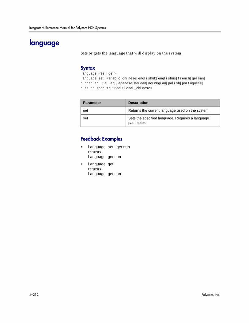
Integrator’s Reference Manual for Polycom HDX Systems
4–212 Polycom, Inc.
languageSets or gets the language that will display on the system.
Syntaxlanguage <set|get>language set <arabic|chinese|englishuk|englishus|french|german|hungarian|italian|japanese|korean|norwegian|polish|portuguese|russian|spanish|traditional_chinese>
Feedback Examples• language set german
returnslanguage german
• language getreturnslanguage german
Parameter Description
get Returns the current language used on the system.
set Sets the specified language. Requires a language parameter.

System Commands
Polycom, Inc. 4–213
lanportSets or gets the LAN port settings of the system.
Syntaxlanport <get|auto|autohdx|autofdx|10hdx|10fdx|100hdx|100fdx|1000hdx|1000fdx>
Feedback Examples• lanport auto
returnslanport autorestart system for changes to take effect. restart now? <y,n>
• lanport getreturnslanport auto
CommentsAfter making a change, you are prompted to restart the system.
Parameter Description
get Returns the current setting.
auto|autohdx|autofdx|10hdx|10fdx|100hdx|100fdx|1000hdx|1000fdx
Sets the LAN speed and duplex mode. This paramater is not allowed while in a call.
auto: Automatically negotiates the LAN speed and duplex mode.
autohdx: Automatically negotiates the LAN speed but specifies half-duplex mode.
autofdx: Automatically negotiates the LAN speed but specifies full-duplex mode.
10hdx: 10 Mbps, half duplex
10fdx: 10 Mbps, full duplex
100hdx: 100 Mbps, half duplex
100fdx: 100 Mbps, full duplex
1000hdx: 1000 Mbps, half duplex
1000fdx: 1000 Mbps, full duplex

Integrator’s Reference Manual for Polycom HDX Systems
4–214 Polycom, Inc.
ldapauthenticationtypeSets or gets the authentication type required to authenticate with an LDAP server.
Syntaxldapauthenticationtype getldapauthenticationtype set <anonymous|basic|ntlm>
Feedback Examples• ldapauthenticationtype get
returnsldapauthenticationtype anonymous
• ldapauthenticationtype set basicreturnsldapauthenticationtype basic
• ldapauthenticationtype set ntlmreturnsldapauthenticationtype ntlm
Parameter Description
get Returns the current setting.
set Sets the authentication type of an LDAP server.
Note: This parameter does not change the setting on the server. Instead, this parameter changes how the Polycom system recognizes the server.
anonymous Specifies “anonymous” as the authentication type of an LDAP server.
basic Specifies “basic” as the authentication type of an LDAP server.
ntlm Specifies “ntlm” as the authentication type of an LDAP server. This is the default setting.

System Commands
Polycom, Inc. 4–215
ldapbasednSets or gets the base distinguished name (DN) of an LDAP server.
Syntaxldapbasedn getldapbasedn set [“base dn”]
Feedback Examples• ldapbasedn get
returnsldapbasedn dc=hardware,dc=domain,dc=Polycom,dc=comwhere:dc=domain component
• ldapbasedn set dc=software,dc=domain,dc=Polycom,dc=comreturnsldapbasedn dc=software,dc=domain,dc=Polycom,dc=comwhere:dc=domain component
Parameter Description
get Returns the current setting.
set Sets the base DN of an LDAP server. To erase the current setting, omit the “base dn” parameter.
Notes: This parameter does not change the setting on the server. Instead, this parameter changes how the Polycom system recognizes the server.
“base dn” Specifies the base DN of an LDAP server.
Valid characters include:
Unicode (ISO-10646) characters, including IA5/ASCII characters and extended characters such as é, Ø, and å.

Integrator’s Reference Manual for Polycom HDX Systems
4–216 Polycom, Inc.
ldapbinddnSets or gets the bind DN for LDAP Simple Authentication.
Syntaxldapbinddn getldapbinddn set [“bind dn”]
Feedback Examples• ldapbinddn get
returnsldapbinddn cn=plcm admin1,ou=plcmsupport,ou=plcmhelp,dc=hardware,dc=domain,dc=polycom,dc=comwhere:cn=common nameou=organizational unitdc=domain component
• ldapbinddn set cn=plcm admin2,ou=plcmaccounts,ou=plcmservice, dc=hardware,dc=domain,dc=polycom,dc=comreturnsldapbinddn cn=plcm admin2,ou=plcmaccounts,ou=plcmservice,dc=hardware,dc=domain,dc=polycom,dc=comwhere:cn=common nameou=organizational unitdc=domain component
Parameter Description
get Returns the current setting.
set Sets the bind DN for LDAP Simple Authentication. To erase the current setting, omit the “bind dn” parameter.
Note: This parameter does not change the setting on the server. Instead, this parameter changes how the Polycom system recognizes the server.
“bind dn” Specifies the bind DN of an LDAP server.
Valid characters include:
Unicode (ISO-10646) characters, including IA5/ASCII characters and extended characters such as é, Ø, and å.

System Commands
Polycom, Inc. 4–217
ldapdirectorySets or gets whether the LDAP directory server is enabled.
Syntaxldapdirectory <get|yes|no>
Feedback Examples• ldapdirectory get
returnsldapdirectory yes
• ldapdirectory noreturnsldapdirectory no
CommentsEach Polycom system supports a single global directory server at any given time. Therefore, enabling the LDAP directory server automatically disables any other global directory server, such as the Polycom GDS directory server, that is enabled.
If the Polycom GDS directory server and another directory server are defined on the system, the Polycom GDS directory server becomes the default directory server after upgrading the system software.
Parameter Description
get Returns the current setting.
yes Enables the LDAP directory server.
no Disables the LDAP directory server. This is the default setting.

Integrator’s Reference Manual for Polycom HDX Systems
4–218 Polycom, Inc.
ldapntlmdomainSets or gets the domain in which authentication takes place in the Active Directory server.
Syntaxldapntlmdomain getldapntlmdomain set [“domain”]
Feedback Examples• ldapntlmdomain get
returnsldapntlmdomain AUSTIN
• ldapntlmdomain set ANDOVERreturnsldapntlmdomain ANDOVER
Parameter Description
get Returns the current setting.
set Sets the domain in which authentication takes place in the Active Directory server. To erase the current setting, omit the “domain” parameter.
Note: This parameter does not change the setting on the server. Instead, this parameter changes how the Polycom system recognizes the server.
“domain” Specifies the domain in which authentication takes place in the Active Directory server.
Valid characters include:
0 through 9, a through z, A through Z, hyphen (-), and period (.)
Note: The domain name cannot begin or end with a hyphen or a period.

System Commands
Polycom, Inc. 4–219
ldappasswordSets the password for Simple or NT LAN Manager (NTLM) authentication of an LDAP server.
Syntaxldappassword set <ntlm|basic> [“password”]
Feedback Examples• ldappassword set ntlm P!cmp@s5wd
returnsldappassword ntlm P!cmp@s5wd
• ldappassword set basic P0!yc0mp@s5returnsldappassword basic P0!yc0mp@s5
Parameter Description
set Sets the password for Simple or NTLM authentication of an LDAP server. To erase the current setting, omit the “password” parameter.
Note: This parameter does not change the setting on the server. Instead, this parameter changes how the Polycom system recognizes the server.
ntlm Specifies setting the password for NTLM authentication of an LDAP server.
basic Specifies setting the password for Simple authentication of an LDAP server.
“password” Specifies the password for Simple or NTLM authentication of an LDAP server.
Valid characters include:
Unicode (ISO-10646) characters, including IA5/ASCII characters and extended characters such as é, Ø, and å.
Note: The server administrator may specify additional restrictions for password creation.
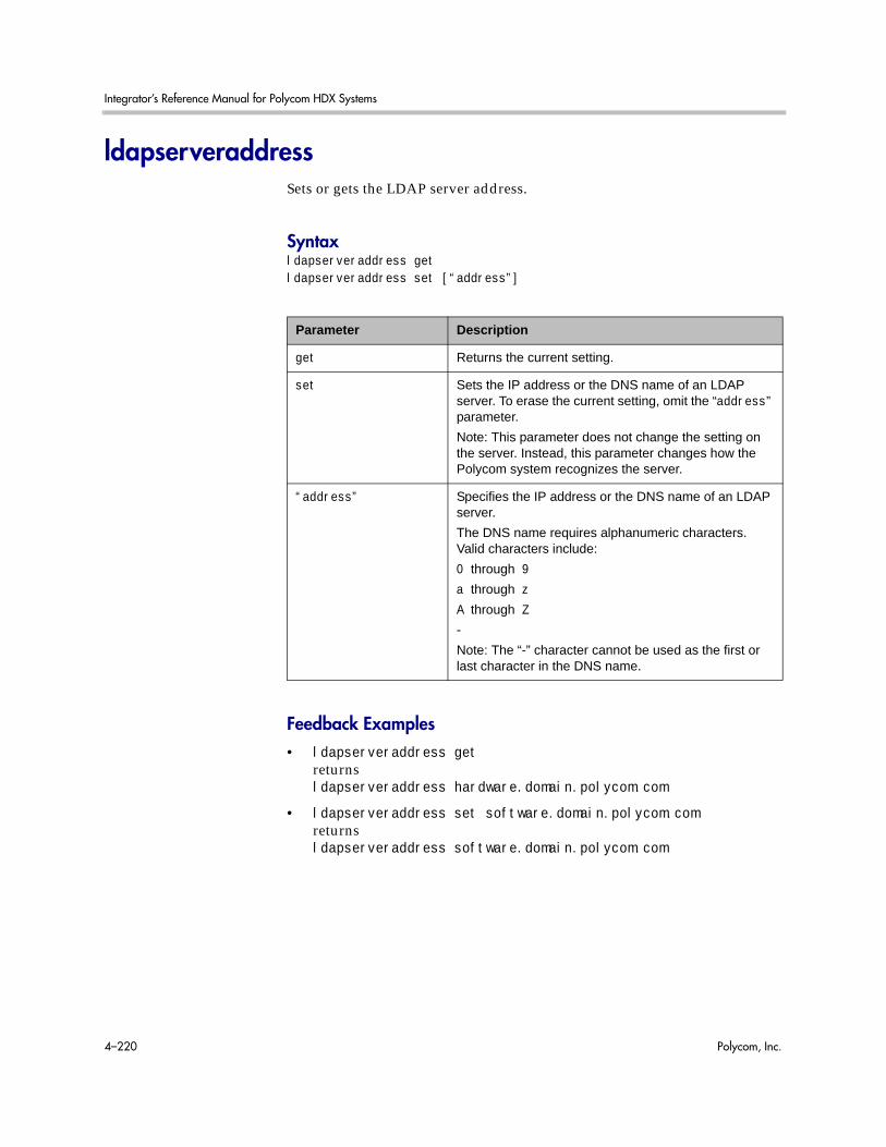
Integrator’s Reference Manual for Polycom HDX Systems
4–220 Polycom, Inc.
ldapserveraddressSets or gets the LDAP server address.
Syntaxldapserveraddress getldapserveraddress set [“address”]
Feedback Examples• ldapserveraddress get
returnsldapserveraddress hardware.domain.polycom.com
• ldapserveraddress set software.domain.polycom.comreturnsldapserveraddress software.domain.polycom.com
Parameter Description
get Returns the current setting.
set Sets the IP address or the DNS name of an LDAP server. To erase the current setting, omit the “address” parameter.
Note: This parameter does not change the setting on the server. Instead, this parameter changes how the Polycom system recognizes the server.
“address” Specifies the IP address or the DNS name of an LDAP server.
The DNS name requires alphanumeric characters. Valid characters include:
0 through 9
a through z
A through Z
-
Note: The “-” character cannot be used as the first or last character in the DNS name.

System Commands
Polycom, Inc. 4–221
ldapserverportSets or gets the port number of an LDAP server.
Syntaxldapserverport getldapserverport set [“port number”]
Feedback Examples• ldapserverport get
returnsldapserverport 389
• ldapserverport set 636returnsldapserverport 636
Parameter Description
get Returns the current setting.
set Sets the port number of an LDAP server. To erase the current setting, omit the “port number” parameter.
Note: This parameter does not change the setting on the server. Instead, this parameter changes how the Polycom system recognizes the server.
“port number” Specifies the port number of an LDAP server. The default setting is 389.

Integrator’s Reference Manual for Polycom HDX Systems
4–222 Polycom, Inc.
ldapsslenabledSets or gets the Secure Sockets Layer (SSL)/Transport Layer Security (TLS) encryption state for LDAP operations.
Syntaxldapsslenabled getldapsslenabled set [on|off]
Feedback Examples• ldapsslenabled get
returnsldapsslenabled off
• ldapsslenabled set onreturnsldapsslenabled on
Parameter Description
get Returns the current setting.
set Sets the SSL encryption state for LDAP operations.
Note: This parameter does not change the setting on the server. Instead, this parameter changes how the Polycom system recognizes the server.
on Specifies “on” as the encryption state for LDAP operations. This is the default setting.
off Specifies “off” as the encryption state for LDAP operations.

System Commands
Polycom, Inc. 4–223
ldapusernameSets or gets the user name for NTLM authentication of an LDAP server.
Syntaxldapusername getldapusername set [“user name”]
Feedback Examples• ldapusername get
returnsldapusername jpolycom
• ldapusername set mpolycomreturnsldapusername mpolycom
Parameter Description
get Returns the current setting.
set Sets the user name for NTLM authentication of an LDAP server. To erase the current setting, omit the “user name” parameter.
Note: This parameter does not change the setting on the server. Instead, this parameter changes how the Polycom system recognizes the server.
“user name” Specifies the user name for NTLM authentication of an LDAP server.
Valid characters include:
Unicode (ISO-10646) characters, including IA5/ASCII characters and extended characters such as é, Ø, and å.

Integrator’s Reference Manual for Polycom HDX Systems
4–224 Polycom, Inc.
linestateSets or gets API session registration to receive notifications about IP or ISDN line state changes.
Syntaxlinestate getlinestate <register|unregister>
Feedback Examples• linestate register
returnslinestate registered
• linestate unregisterreturnslinestate unregistered
• linestate getreturnslinestate unregistered
CommentsIP line state changes are only received in a serial API session.
Parameter Description
get Returns the current setting.
register Registers to receive notification when IP or ISDN line states change.
unregister Unregisters to receive notification when IP or ISDN line states change.

System Commands
Polycom, Inc. 4–225
listenRegisters the RS-232 session to listen for incoming video calls, phone calls, or system sleep or awake state and, consequently, to give notification when the registered state occurs.
Syntaxlisten <video|phone|sleep>
Feedback Examples• listen sleep
returnslisten sleep registeredto acknowledge that the session is now registered to listen for sleep mode
• listen phonereturnslisten phone registeredto acknowledge that the session is now registered to listen for incoming phone calls
• listen videoreturnslisten video registeredto acknowledge that the session is now registered to listen for incoming video calls
Parameter Description
video Instructs the session to listen for incoming video calls. When this event occurs, the message “listen video ringing” is received.
phone Instructs the session to listen for incoming phone calls. When this event occurs, the message “listen phone ringing” is received.
sleep Instructs the session to listen for when the system goes into sleep mode. When this event occurs, the message “listen going to sleep” is received. When the system wakes up, the message “listen waking up” is received. Deprecated. Polycom recommends using sleep register instead of this command.

Integrator’s Reference Manual for Polycom HDX Systems
4–226 Polycom, Inc.
localdatetimeSets or gets whether to display the local date and time on the Home screen.
Syntaxlocaldatetime <get|yes|no>
Feedback Examples• localdatetime yes
returnslocaldatetime yes
• localdatetime noreturnslocaldatetime no
• localdatetime getreturnslocaldatetime no
Parameter Description
get Returns the current setting.
yes Displays the local date and time on the Home screen.
no Removes the local date and time from the Home screen.

System Commands
Polycom, Inc. 4–227
loginwindowduration Sets or gets the duration of time within which failed logins can lead to account lockout.
Syntaxloginwindowduration <get|set>
Feedback Examples• loginwindowduration get
returnsloginwindowduration 2
• loginwindowduration set 1returnsloginwindowduration 1
• loginwindowduration set offreturnsloginwindowduration off
Comments• When the HDX system is powered off, the time window within which
failed logins can lead to account lockout is still in effect.
• Login window duration begins at the first failed login attempt and lasts until the login window duration expires or the user successfully logs in.
• If loginwindowduration is set to off, the user is locked out after consecutive failures regardless of the time window.
Parameter Description
get Returns the current setting.
set Sets the time window within which failed logins can lead to account lockout. Time is measured in hours. Valid values are: off and {1..24}

Integrator’s Reference Manual for Polycom HDX Systems
4–228 Polycom, Inc.
marqueedisplaytextSets or gets the text to display in the dialing entry field on the Place a Call screen.
Syntaxmarqueedisplaytext getmarqueedisplaytext set “text”
Feedback Examples• marqueedisplaytext set “Select an entry from the directory.”
returnsmarqueedisplaytext “Select an entry from the directory.”
• marqueedisplaytext getreturnsmarqueedisplaytext “Select an entry from the directory.”
Parameter Description
get Returns the current marquee display text.
set Sets the text to display in the dialing entry field followed by the text to use. Enclose the string in quotation marks if it includes spaces.
“text” Text to display. Enclose the character string in quotation marks if it includes spaces. If “text” is omitted, the system automatically sets it to Welcome.

System Commands
Polycom, Inc. 4–229
maxgabinternationalcallspeedSets or gets the maximum speed for international ISDN calls made from the global directory. This command is only applicable if you have an ISDN network interface connected to your system.
Syntaxmaxgabinternationalcallspeed getmaxgabinternationalcallspeed set “valid speed”
Feedback Examples• maxgabinternationalcallspeed set 128
returnsmaxgabinternationalcallspeed 128
• maxgabinternationalcallspeed getreturnsmaxgabinternationalcallspeed 128
Parameter Description
get Returns the current valid speed.
set Sets the maximum speed for international calls when followed by a valid speed value.
“valid speed” Valid speeds are: 2x64, 128, 256, 384, 512, 768, 1024, and 1472 kbps.

Integrator’s Reference Manual for Polycom HDX Systems
4–230 Polycom, Inc.
maxgabinternetcallspeedSets or gets the maximum speed for Internet (IP/H.323) calls made from the global directory.
Syntaxmaxgabinternetcallspeed getmaxgabinternetcallspeed set “valid speed”
Feedback Examples• maxgabinternetcallspeed set 384
returnsmaxgabinternetcallspeed 384
• maxgabinternetcallspeed getreturnsmaxgabinternetcallspeed 384
Parameter Description
get Returns the current valid speed.
set Sets the maximum speed for Internet calls when followed by a valid speed value.
“valid speed” Valid speeds are: 128, 256, 384, 512, 768, 1024, and 1472 kbps.

System Commands
Polycom, Inc. 4–231
maxgabisdncallspeedSets or gets the maximum speed for ISDN (H.320) calls made from the global directory. This command is only applicable if you have an ISDN network interface connected to your system.
Syntaxmaxgabisdncallspeed getmaxgabisdncallspeed set “valid speed”
Feedback Examples• maxgabisdncallspeed set 384
returnsmaxgabisdncallspeed 384
• maxgabisdncallspeed getreturnsmaxgabisdncallspeed 384
Parameter Description
get Returns the current valid speed.
set Sets the maximum speed for ISDN calls when followed by a valid speed value.
“valid speed” Valid speeds are: 56, 64, 128, 256, 384, 512, 768, 1024, and 1472 kbps.
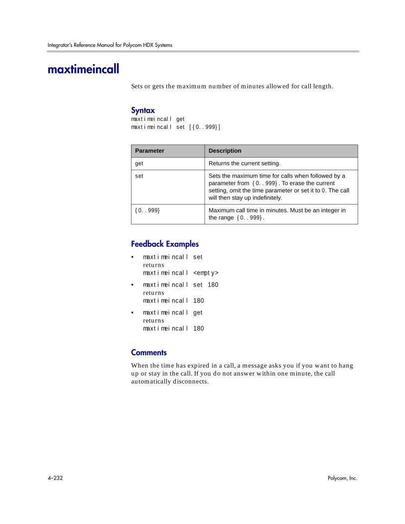
Integrator’s Reference Manual for Polycom HDX Systems
4–232 Polycom, Inc.
maxtimeincallSets or gets the maximum number of minutes allowed for call length.
Syntaxmaxtimeincall getmaxtimeincall set [{0..999}]
Feedback Examples• maxtimeincall set
returnsmaxtimeincall <empty>
• maxtimeincall set 180returnsmaxtimeincall 180
• maxtimeincall getreturnsmaxtimeincall 180
CommentsWhen the time has expired in a call, a message asks you if you want to hang up or stay in the call. If you do not answer within one minute, the call automatically disconnects.
Parameter Description
get Returns the current setting.
set Sets the maximum time for calls when followed by a parameter from {0..999}. To erase the current setting, omit the time parameter or set it to 0. The call will then stay up indefinitely.
{0..999} Maximum call time in minutes. Must be an integer in the range {0..999}.

System Commands
Polycom, Inc. 4–233
mcupasswordEnters and sends the MCU password to the MCU.
Syntaxmcupassword [“password”]
Parameter Description
password Specifies the password to send to the MCU.

Integrator’s Reference Manual for Polycom HDX Systems
4–234 Polycom, Inc.
meetingpasswordSets the meeting password.
Syntaxmeetingpassword set [“password”]
Feedback Examples• meetingpassword set psswd
returnsmeetingpassword psswd
• meetingpassword set “My psswd”returnserror: command has illegal parameters
CommentsTo receive a notification that the password has failed, you must use the popupinfo register command to register the current API session to receive popup text.
See AlsoSee also the related popupinfo command on page 4-268.
Parameter Description
set Sets the meeting password if followed by the password parameter. To erase the current setting, omit the password parameter.
“password” User-defined password. Valid characters are: A through Z (lower and uppercase), -, _, @, /, ;, ,, ., \, and 0 through 9. The length is limited to 33 characters. The password cannot include spaces.

System Commands
Polycom, Inc. 4–235
monitor1 (deprecated)Sets or gets the aspect ratio for Monitor 1. With the implementation of the configdisplay command on page 4-77, this command has been deprecated.
Syntaxmonitor1 <get|4:3|16:9|vga>
Feedback Examples• monitor1 4:3
returnsmonitor1 4:3
• monitor1 16:9returnsmonitor1 16:9
• monitor1 getreturnsmonitor1 16:9
See AlsoSee the configdisplay command on page 4-77.
Parameter Description
get Returns the current setting.
4:3|16:9 Sets the display aspect ratio to 4:3 (standard) or 16:9 (wide screen).
vga Sets the display to VGA and causes the system to restart.

Integrator’s Reference Manual for Polycom HDX Systems
4–236 Polycom, Inc.
monitor1screensaveroutputSets or gets whether to send either black video or "No Signal" to Monitor 1 when the screen saver activates.
Syntaxmonitor1screensaveroutput <get|black|no_signal>
Feedback Examples• monitor1screensaveroutput black
returnsmonitor1screensaveroutput black
• monitor1screensaveroutput no_signalreturnsmonitor1screensaveroutput no_signal
• monitor1screensaveroutput getreturnsmonitor1screensaveroutput no_signal
See AlsoSee the monitor2screensaveroutput command on page 4-238.
Parameter Description
get Returns the current setting.
black Sends black video to Monitor 1 when the system goes to sleep and the screen saver activates.
no_signal Sends no signal to Monitor 1 when the system goes to sleep and the screen saver activates.

System Commands
Polycom, Inc. 4–237
monitor2 (deprecated)Sets or gets the aspect ratio for Monitor 2. With the implementation of the configdisplay command on page 4-77, this command has been deprecated.
Syntaxmonitor2 offmonitor2 <get|4:3|16:9>monitor2 vga
Feedback Examples• monitor2 off
returnsmonitor2 off
• monitor2 16:9returnsmonitor2 16:9
• monitor2 getreturnsmonitor2 16:9
See AlsoSee the configdisplay command on page 4-77.
Parameter Description
off Disables the second monitor output.
get Returns the current setting.
4:3|16:9 Sets the aspect ratio to 4:3 (standard) or 16:9 (wide screen).
vga Sets the display to VGA.

Integrator’s Reference Manual for Polycom HDX Systems
4–238 Polycom, Inc.
monitor2screensaveroutputSets or gets whether to send either black video or "No Signal" to Monitor 2 when the screen saver activates.
Syntaxmonitor2screensaveroutput <get|black|no_signal>
Feedback Examples• monitor2screensaveroutput black
returnsmonitor2screensaveroutput black
• monitor2screensaveroutput no_signalreturnsmonitor2screensaveroutput no_signal
• monitor2screensaveroutput getreturnsmonitor2screensaveroutput no_signal
See AlsoSee the monitor1screensaveroutput command on page 4-236.
Parameter Description
black Sends black video to Monitor 2 when the system goes to sleep and the screen saver activates.
no_signal Sends no signal to Monitor 2 when the system goes to sleep and the screen saver activates.
get Returns the current setting.
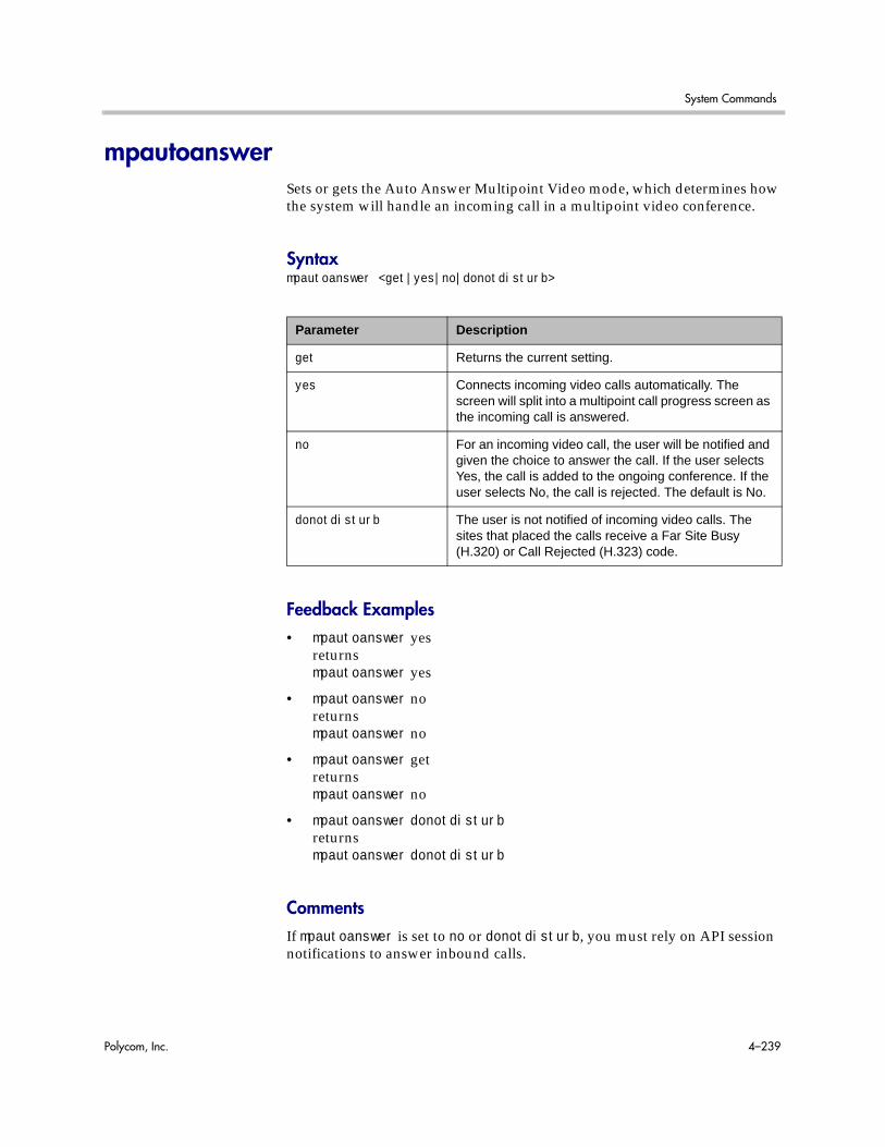
System Commands
Polycom, Inc. 4–239
mpautoanswerSets or gets the Auto Answer Multipoint Video mode, which determines how the system will handle an incoming call in a multipoint video conference.
Syntaxmpautoanswer <get|yes|no|donotdisturb>
Feedback Examples• mpautoanswer yes
returnsmpautoanswer yes
• mpautoanswer noreturnsmpautoanswer no
• mpautoanswer getreturnsmpautoanswer no
• mpautoanswer donotdisturbreturnsmpautoanswer donotdisturb
CommentsIf mpautoanswer is set to no or donotdisturb, you must rely on API session notifications to answer inbound calls.
Parameter Description
get Returns the current setting.
yes Connects incoming video calls automatically. The screen will split into a multipoint call progress screen as the incoming call is answered.
no For an incoming video call, the user will be notified and given the choice to answer the call. If the user selects Yes, the call is added to the ongoing conference. If the user selects No, the call is rejected. The default is No.
donotdisturb The user is not notified of incoming video calls. The sites that placed the calls receive a Far Site Busy (H.320) or Call Rejected (H.323) code.

Integrator’s Reference Manual for Polycom HDX Systems
4–240 Polycom, Inc.
mpmodeSets or gets the multipoint conference viewing mode for the system in a multipoint call. The multipoint mode can be set to auto, discussion, presentation, or fullscreen. By default, it is set to auto.
Syntaxmpmode <get|auto|discussion|presentation|fullscreen>
Feedback Examples• mpmode auto
returnsmpmode auto
• mpmode discussionreturnsmpmode discussion
• mpmode getreturnsmpmode discussion
CommentsThis option is not available unless the multipoint option is enabled.
Parameter Description
get Returns the current setting.
auto In Auto mode, the system switches between Full Screen Mode and Discussion mode, depending on the interaction between the sites. If one site is talking uninterrupted for 15 seconds or more, the speaker appears full screen.
presentation In Presentation mode, the person who is speaking appears full screen to the far sites, while the person who is speaking sees all the other sites on a split screen.
discussion In Discussion mode (also called Continuous Presence mode), every site sees all the sites in the meeting at the same time, on a split screen.
fullscreen In Full Screen mode, every site in the call sees the current speaker, or the latest person to speak, on the full screen.

System Commands
Polycom, Inc. 4–241
What you see during a multipoint call can depend on many factors such as the system’s monitor configuration, the number of sites in the call, whether content is shared, and whether dual monitor emulation is used.

Integrator’s Reference Manual for Polycom HDX Systems
4–242 Polycom, Inc.
mtumodeSets or gets the MTU mode. The mtumode and mtusize commands allow you to change the Maximum Transmission Unit (MTU) size, to adjust for the best interoperability with the host network. Set mtumode to specify, then use mtusize to specify a value. If mtumode is set to default, the system automatically sets the MTU value to 1260.
Syntaxmtumode <get|default|specify>
Feedback Examples• mtumode default
returnsmtumode default
• mtumode specifyreturnsmtumode specify
• mtumode getreturnsmtumode specify
• mtusize 660returnsmtusize 660
• mtumode fooreturnserror: command has illegal parameters
See AlsoSee also the related mtusize command on page 4-243.
Parameter Description
get Returns the current setting.
default Sets the Maximum Transmission Unit size to the default value of 1260.
specify Allows you to specify a Maximum Transmission Unit size other than the default setting.
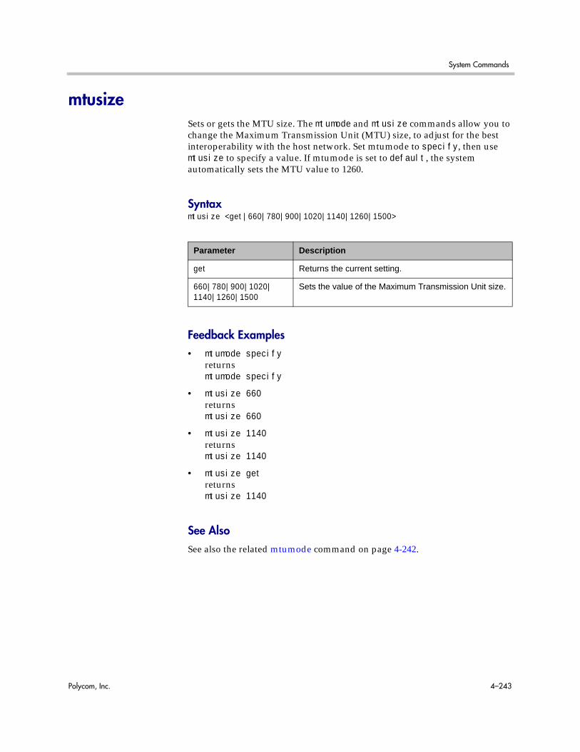
System Commands
Polycom, Inc. 4–243
mtusizeSets or gets the MTU size. The mtumode and mtusize commands allow you to change the Maximum Transmission Unit (MTU) size, to adjust for the best interoperability with the host network. Set mtumode to specify, then use mtusize to specify a value. If mtumode is set to default, the system automatically sets the MTU value to 1260.
Syntaxmtusize <get|660|780|900|1020|1140|1260|1500>
Feedback Examples• mtumode specify
returnsmtumode specify
• mtusize 660returnsmtusize 660
• mtusize 1140returnsmtusize 1140
• mtusize getreturnsmtusize 1140
See AlsoSee also the related mtumode command on page 4-242.
Parameter Description
get Returns the current setting.
660|780|900|1020|1140|1260|1500
Sets the value of the Maximum Transmission Unit size.

Integrator’s Reference Manual for Polycom HDX Systems
4–244 Polycom, Inc.
muteSets or gets the near or far site mute settings.
Syntaxmute <register|unregister>mute near <get|on|off|toggle>mute far get
Feedback Examples• mute register
returnsmute registered
• mute near onreturnsmute near on
• mute far getreturnsmute far off
CommentsIn register mode, the system sends notification to the API session when the far or near site is muted or unmuted.
Parameter Description
register Registers to receive notification when the mute mode changes.
unregister Disables register mode.
near Sets the command for the near site. Requires on, off, toggle, or get.
get Returns the current setting for the near or far site.
on Mutes the near site (mute near on).
off Unmutes the near site (mute near off).
toggle If mute near mode is mute near on, this switches to mute near off, and vice versa.
far Returns the mute state of the far site system. Requires the parameter get.
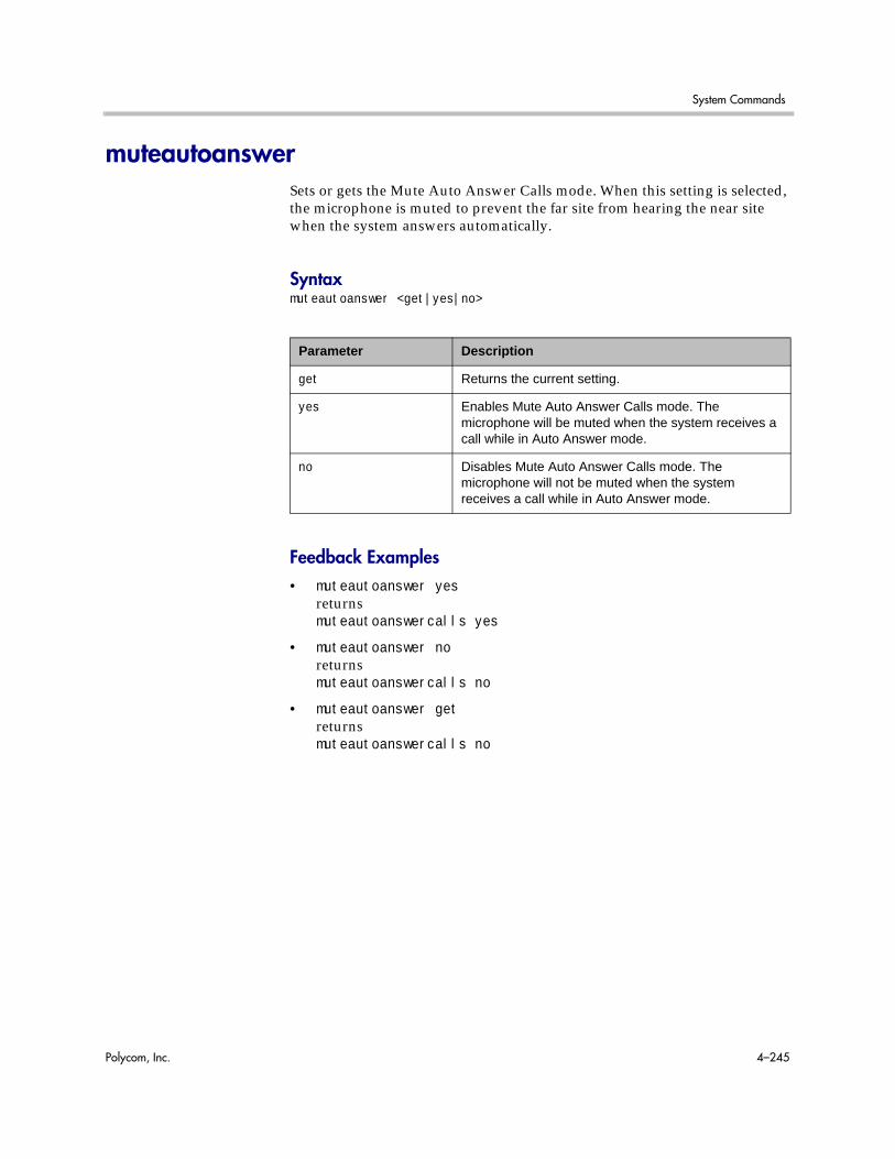
System Commands
Polycom, Inc. 4–245
muteautoanswerSets or gets the Mute Auto Answer Calls mode. When this setting is selected, the microphone is muted to prevent the far site from hearing the near site when the system answers automatically.
Syntaxmuteautoanswer <get|yes|no>
Feedback Examples• muteautoanswer yes
returnsmuteautoanswercalls yes
• muteautoanswer noreturnsmuteautoanswercalls no
• muteautoanswer getreturnsmuteautoanswercalls no
Parameter Description
get Returns the current setting.
yes Enables Mute Auto Answer Calls mode. The microphone will be muted when the system receives a call while in Auto Answer mode.
no Disables Mute Auto Answer Calls mode. The microphone will not be muted when the system receives a call while in Auto Answer mode.

Integrator’s Reference Manual for Polycom HDX Systems
4–246 Polycom, Inc.
natconfigSets or gets the NAT configuration.
Syntaxnatconfig <get|auto|manual|off>
Feedback Examples• natconfig auto
returnsnatconfig auto
• natconfig manualreturnsnatconfig manual
• natconfig offreturnsnatconfig off
• natconfig getreturnsnatconfig off
Parameter Description
get Returns the current setting.
auto Specifies that the system is behind a NAT; specifies that the system will automatically discover the public (WAN) address.
manual Specifies that the system is behind a NAT. Requires the WAN address to be assigned using the wanipaddress command on page 4-363.
off Disables the option when the system is not behind a NAT.

System Commands
Polycom, Inc. 4–247
nath323compatibleSets or gets the NAT is H.323 Compatible setting.
Syntaxnath323compatible <get|yes|no>
Feedback Examples• nath323compatible yes
returnsnath323compatible yes
• nath323compatible noreturnsnath323compatible no
• nath323compatible getreturnsnath323compatible no
Parameter Description
get Returns the current setting.
yes Specifies that NAT is capable of translating H.323 traffic.
no Specifies that NAT is not capable of translating H.323 traffic.

Integrator’s Reference Manual for Polycom HDX Systems
4–248 Polycom, Inc.
nearloopActivates or deactivates the Near End Loop test.
Syntaxnearloop <on|off>
Feedback Examples• nearloop on
returnsnearloop on
• nearloop offreturnsnearloop off
CommentsWhen Near End Loop is on, you can test the encoder/decoder on the system. This test is not available when you are in a call.
Parameter Description
on Activates the Near End Loop, a complete internal test of the system.
off Deactivates the Near End Loop.

System Commands
Polycom, Inc. 4–249
netstatsReturns network statistics for each call.
Syntaxnetstats [{0..n}]
Feedback Examples• netstats 2
returnscall:1 txrate:128 K rxrate:128 K pktloss:0 %pktloss:0.0 % tvp:H.263rvp:H.263 tvf:CIF rvp:CIF tap:G.722.1 rap:G.722.1 tcp:H.323 rcp:H.323where:txrate=transmit clock raterxrate=receive clock ratepktloss=number of packet loss/errors%pktloss=percentage of packet loss/errorstvp=transmit video protocolrvp=receive video protocoltvf=transmit video formatrvf=receive video formattap=transmit audio protocolrap=receive audio protocoltcp=transmit comm protocolrcp=receive comm protocol
Parameter Description
{0..n} Call in a multipoint call, where n is the maximum number of calls supported by the system. 0 is the first site connected. If no call is specified, netstats returns information about the near site.

Integrator’s Reference Manual for Polycom HDX Systems
4–250 Polycom, Inc.
nonotifyUnregisters the API client to receive status notifications.
Syntaxnonotify <callstatus|captions|linestatus|mutestatus|screenchanges>nonotify <sysstatus|sysalerts|vidsourcechanges>
Feedback Examples• nonotify callstatus
returns nonotify callstatus success
• If entered again,nonotify callstatusreturns info: event/notification not active:callstatus
• nonotify calendarmeetingsreturnsnonotify calendarmeetings success
See AlsoSee the related notify command on page 4-251.
Parameter Description
calendarmeetings Stops the system from receiving meeting reminders.
callstatus Stops the system from receiving changes in call status, such as a connection or disconnection.
captions Stops the system from capturing closed captions as they appear on the screen.
linestatus Stops the system from receiving line status notifications.
mutestatus Stops the system from receiving changes in audio mute status.
screenchanges Stops the system from receiving notification when a user interface screen is displayed.
sysstatus Stops the system from receiving system status notifications.
sysalerts Stops the system from receiving system alerts.
vidsourcechanges Stops the system from receiving notification of camera source changes.

System Commands
Polycom, Inc. 4–251
notifyLists the notification types that are currently being received, or registers to receive status notifications.
Syntaxnotify notify <callstatus|captions|linestatus|mutestatus|screenchanges>notify <sysstatus|sysalerts|vidsourcechanges>notify calendarmeetings
Parameter Description
notify Lists the notification types that are currently being received, in the following format:
registered for <num> notifications[:notification type>...]
calendarmeetings Registers the API client to receive meeting reminders.
callstatus Registers the system to receive changes in call status, such as a connection or disconnection, in the following format:
notification:callstatus:<call direction>:<call id>:<far site name>:<far site number>:<connection status>:<call speed>:<status-specific cause code from call engine>:<calltype>
captions Registers the system to capture closed captions as they appear on the screen, in the following format:
notification:caption:<“caption string”>
linestatus Registers the system to receive line status notifications as they occur, in the following format:
notification:linestatus:<direction>:<call id>:<line id>:<channel id>:<connection status>
mutestatus Registers the system to receive changes in audio mute status, in the following format:
notification:mutestatus:<near or far>:<call id>:<site name>:<site number>:<mute status>
screenchanges Registers the system to receive notification when a user interface screen is displayed, in the following format:
notification:screenchange:<screen name>:<screen def name>

Integrator’s Reference Manual for Polycom HDX Systems
4–252 Polycom, Inc.
Feedback Examples• notify mutestatus
returns notify mutestatus successacknowledging that the session is now registered to receive mutestatus notifications
• notify callstatusreturns notify callstatus successacknowledging that the session is now registered to receive callstatus notifications
• If entered again,notify callstatusreturns info: event/notification already active:callstatus
• notifyreturnsregistered for 2 notifications:mutestatus:
• notify calendarmeetingsreturnsnotify calendarmeetings success
The following are examples of notifications that may be returned after registering to receive them.
• notification:callstatus:outgoing:34:Polycom HDX Demo:192.168.1.101:connected:384:0:videocall
• notification:mutestatus:near:near:near:near:muted
• notification:screenchange:systemsetup:systemsetup_a
sysstatus Registers the system to receive system status notifications, in the following format:
notification:sysstatus:<sys parameter name>:<value1>[:<value2>...]
sysalerts Registers the system to receive system alerts, in the following format:
notification:sysalert:<alert name>:<value1>[:<value2>...]
vidsourcechanges Registers the system to receive notification of camera source changes, in the following format:
notification:vidsourcechange:<near or far>:<camera index>:<camera name>:<people or content>
Parameter Description

System Commands
Polycom, Inc. 4–253
• notification:vidsourcechange:near:1:Main:people
• notification:linestatus:outgoing:32:0:0:disconnected
• notification:vidsourcechange:near:6:ppcip:content
• notification:vidsourcechange:near:none:none:content
• notification: calendarmeetings: AAAaAEFsZXguTWFjRG9uYWxkQHBvbHljb20uY29tAVEACIjMne2/ndgARgAAAADr9GlhsSjWEZBcAAKzMphJBwA4wicbtr3UEZArAKAk09LtAAACZpKWAADe7hJleQIOS7j2mzRJxkLKAAADI/G8AAAQ:Product Planning:10
CommentsThe notify callstatus command registers the current API session for call status notifications. The API client receives call status notifications as a call progresses.
Registration for status notifications is session-specific. For example, registering for alerts in a Telnet session does not return alerts in a simultaneous RS-232 session with the same system.
The notify captions command registers the current API session to receive notifications as closed captions are displayed. If closed captions are dropped for some reason, no notification is received. This command is typically used for capturing captions being displayed for archival purpose.
Duplicate registrations produce another success response. The notify setting remains in effect, even if you restart the system or update the software with system settings saved.
See AlsoSee also the nonotify command on page 4-250 and the callinfo command on page 4-61.

Integrator’s Reference Manual for Polycom HDX Systems
4–254 Polycom, Inc.
ntpmodeSets or gets the mode of the system’s Network Time Protocol (NTP) server. NTP server time is used to ensure synchronized time data in the local Call Detail Report.
Syntaxntpmode <get|auto|off|manual>
Feedback Examples• ntpmode auto
returnsntpmode auto
• ntpmode offreturnsntpmode off
• ntpmode manualreturnsntpmode manual
• ntpmode getreturnsntpmode manual
See AlsoSee the ntpserver command on page 4-256.
Parameter Description
get Returns the current time server mode.
auto Automatically selects an NTP server from the Internet.
off Turns off the use of an NTP server.
manual Lets you specify a server using the ntpserver command on page 4-256.

System Commands
Polycom, Inc. 4–255
ntpsecondaryserverSets or gets a secondary Network Time Protocol (NTP) server using the IP address or DNS name of the server.
Syntaxntpsecondaryserver getntpsecondaryserver set ["xxx.xxx.xxx.xxx"|"server name"]
Feedback Examples• ntpsecondaryserver set
returnsntpsecondaryserver <empty>
• ntpsecondaryserver set 172.26.44.22returnsntpsecondaryserver 172.26.44.22
• ntpsecondaryserver getreturnsntpsecondaryserver 172.26.44.22
CommentsThe primary NTP server must be configured in order to configure the secondary NTP server
See Alsontpserver on page 4-256.
Parameter Description
get Gets the IP address of the secondary NTP server.
set Sets the IP address of the secondary NTP server when followed by a valid parameter. To erase the current setting, omit the ["xxx.xxx.xxx.xxx"|"server name"] parameter.
"xxx.xxx.xxx.xxx" The IP address of the secondary NTP server.
"server name" The DNS name of the secondary NTP server

Integrator’s Reference Manual for Polycom HDX Systems
4–256 Polycom, Inc.
ntpserverSets or gets an Network Time Protocol (NTP) server, using the IP address or the DNS name of the server.
Syntaxntpserver getntpserver set [“xxx.xxx.xxx.xxx”|“server name”]
Feedback Examples• ntpserver set
returnsntpserver <empty>
• ntpserver set 192.168.1.205returnsntpserver 192.168.1.205
• ntpserver getreturnsntpserver 192.168.1.205
CommentsThis command allows you to use an internal time server and thus synchronize the system’s time with the time on your internal network. The system uses this time only for the local Call Detail Report.
See Alsontpsecondaryserver command on page 4-255.
Parameter Description
get Gets the IP address of the NTP server.
set Sets the IP address of the NTP server when followed by a valid parameter. To erase the current setting, omit the [“xxx.xxx.xxx.xxx”|“server name”] parameter.
“xxx.xxx.xxx.xxx” The IP address of the NTP server.
“server name” The DNS name of the NTP server.

System Commands
Polycom, Inc. 4–257
numberofmonitors (deprecated)Returns the number of display monitors configured. With the implementation of the configdisplay command on page 4-77, this command has been deprecated.
Syntaxnumberofmonitors get
Feedback Examples• numberofmonitors get
returnsnumberofmonitors 1when one monitor is configured for display
• numberofmonitors getreturnsnumberofmonitors 2when two monitors are configured for display
See AlsoThe recommended command for accessing display configuration is the configdisplay command on page 4-77. For example, to determine the state of Monitor 2, use configdisplay monitor2 get.

Integrator’s Reference Manual for Polycom HDX Systems
4–258 Polycom, Inc.
numdigitsdidSets or gets the number of digits in the DID Gateway number (E.164 dialing).
Syntaxnumdigitsdid <get|{0..24}>
Feedback Examples• numdigitsdid 7
returnsnumdigitsdid 7
• numdigitsdid getreturnsnumdigitsdid 7
CommentsThe number of digits in the DID is that portion of the full DID that the Gateway will be given from the ISDN service provider as the Called Party Line Identifier. This, in turn, will be passed to the Gatekeeper for address resolution.
Parameter Description
get Returns the current setting.
{0..24} Specifies the number of digits in DID numbers.

System Commands
Polycom, Inc. 4–259
numdigitsextSets or gets the number of digits in the Number+Extension Gateway number (E.164 dialing).
Syntaxnumdigitsext <get|{0..24}>
Feedback Examples• numdigitsext 10
returnsnumdigitsext 10
• numdigitsext getreturnsnumdigitsext 10
CommentsThe number of digits in that number is that portion of the full Number+Extension number that the Gateway will be given from the ISDN service provider as the Called Party Line Identifier. This, in turn, will be passed to the Gatekeeper for address resolution.
Parameter Description
get Returns the current setting.
{0..24} The number of digits in the gateway number if gatewaynumbertype command on page 4-149 is set to number+extension.

Integrator’s Reference Manual for Polycom HDX Systems
4–260 Polycom, Inc.
ocsdirectoryEnable Polycom HDX systems to retrieve and display the Microsoft Office Communications Server contact list and to disable other global directory services.
Syntaxocsdirectory <get|yes|no>
Feedback Examples• ocsdirectory get
returnsocsdirectory yes
• ocsdirectory noreturnsocsdirectory no
CommentsPolycom HDX systems must be registered with the Microsoft Office Communications Server 2007 directory server to enable the Microsoft Office Communications Server 2007 directory service.
Each Polycom HDX system supports a single global directory server at any given time. Therefore, enabling the Microsoft Office Communications Server 2007 automatically disables any other enabled global directory server, such as the Polycom GDS or LDAP directory server.
Parameter Description
get Returns the current setting.
yes Enables the Microsoft Office Communications Server 2007 directory server.
no Disables the Microsoft Office Communications Server 2007 directory server. This is the default setting.
Polycom software versions 3.0 and later also support Microsoft Lync Server 2010. Refer to the Administrator’s Guide for Polycom HDX Systems for more information.
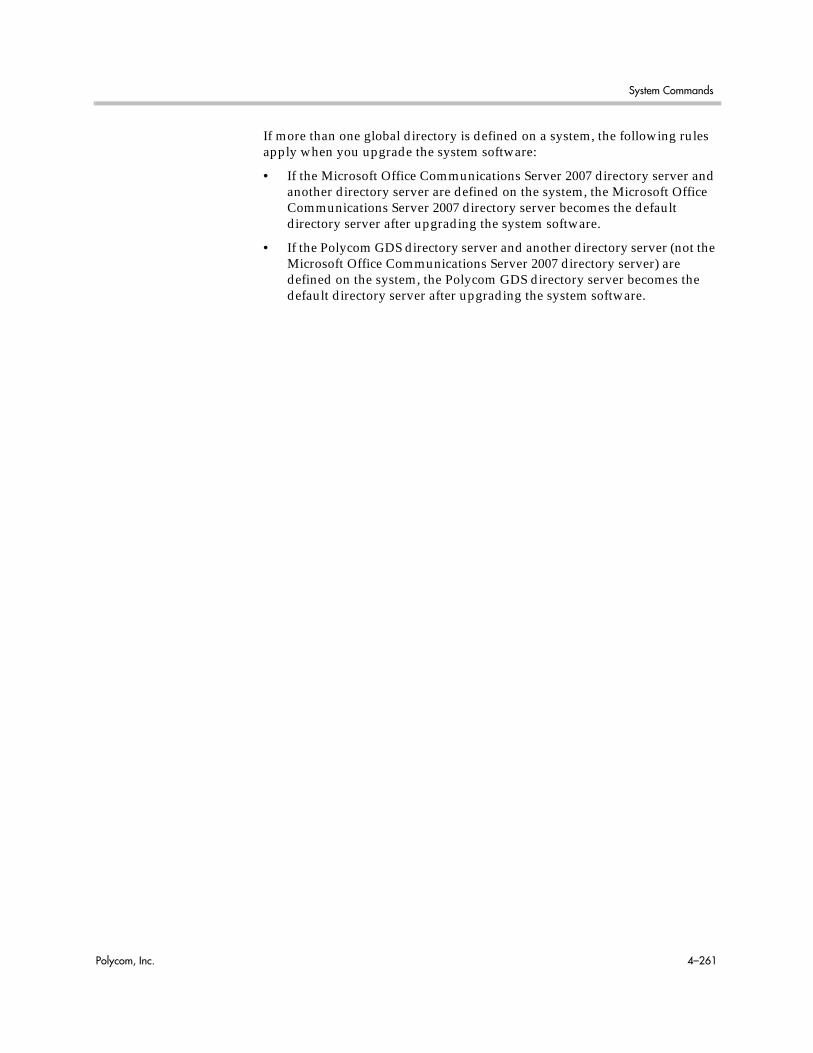
System Commands
Polycom, Inc. 4–261
If more than one global directory is defined on a system, the following rules apply when you upgrade the system software:
• If the Microsoft Office Communications Server 2007 directory server and another directory server are defined on the system, the Microsoft Office Communications Server 2007 directory server becomes the default directory server after upgrading the system software.
• If the Polycom GDS directory server and another directory server (not the Microsoft Office Communications Server 2007 directory server) are defined on the system, the Polycom GDS directory server becomes the default directory server after upgrading the system software.

Integrator’s Reference Manual for Polycom HDX Systems
4–262 Polycom, Inc.
oobcompleteCompletes the setup wizard and restarts the Polycom HDX system.
Syntax oobcomplete
Feedback Examplesoobcompletereturnsoobcomplete
CommentsThe oobcomplete command is processed only when the Polycom HDX system is in setup wizard mode.
To execute oobcomplete successfully, the Polycom HDX system name must be configured.

System Commands
Polycom, Inc. 4–263
pausePauses the command interpreter before executing the next command. Pauses are useful when commands are retrieved from a script file.
Syntaxpause {0..65535}
Feedback Examples• pause 3
returnspausing for 3 seconds
• pause 0returnspausing for 0 seconds
Parameter Description
{0..65535} Number of seconds to pause.

Integrator’s Reference Manual for Polycom HDX Systems
4–264 Polycom, Inc.
peoplevideoadjustment
Sets or gets the people video adjustment setting.
Syntaxpeoplevideoadjustment <get|normal|stretch|zoom>
Feedback Examples• peoplevideoadjustment zoom
returnspeoplevideoadjustment zoom
• peoplevideoadjustment stretchreturnspeoplevideoadjustment stretch
• peoplevideoadjustment normalreturnspeoplevideoadjustment normal
• peoplevideoadjustment getreturnspeoplevideoadjustment normal
Parameter Description
get Returns the current setting.
normal Preserves the aspect ratio of the source video. The image is scaled (if necessary) to the largest supported resolution that fits on the display without cropping.
stretch Does not preserve aspect ratio. The image is scaled horizontally and vertically to exactly match the resolution of the display.
zoom Preserves the aspect ratio of the source video. The image is scaled to exactly match one of the display dimensions while matching or exceeding the other display dimension. The image is centered and cropped.

System Commands
Polycom, Inc. 4–265
phoneFlashes the analog phone line.
Syntaxphone <clear|flash>
See AlsoUse the flash command on page 4-135 to specify a call ID.
Parameter Description
clear Clears phone number from the text box.
flash Sends flash hook to a POTS connection.
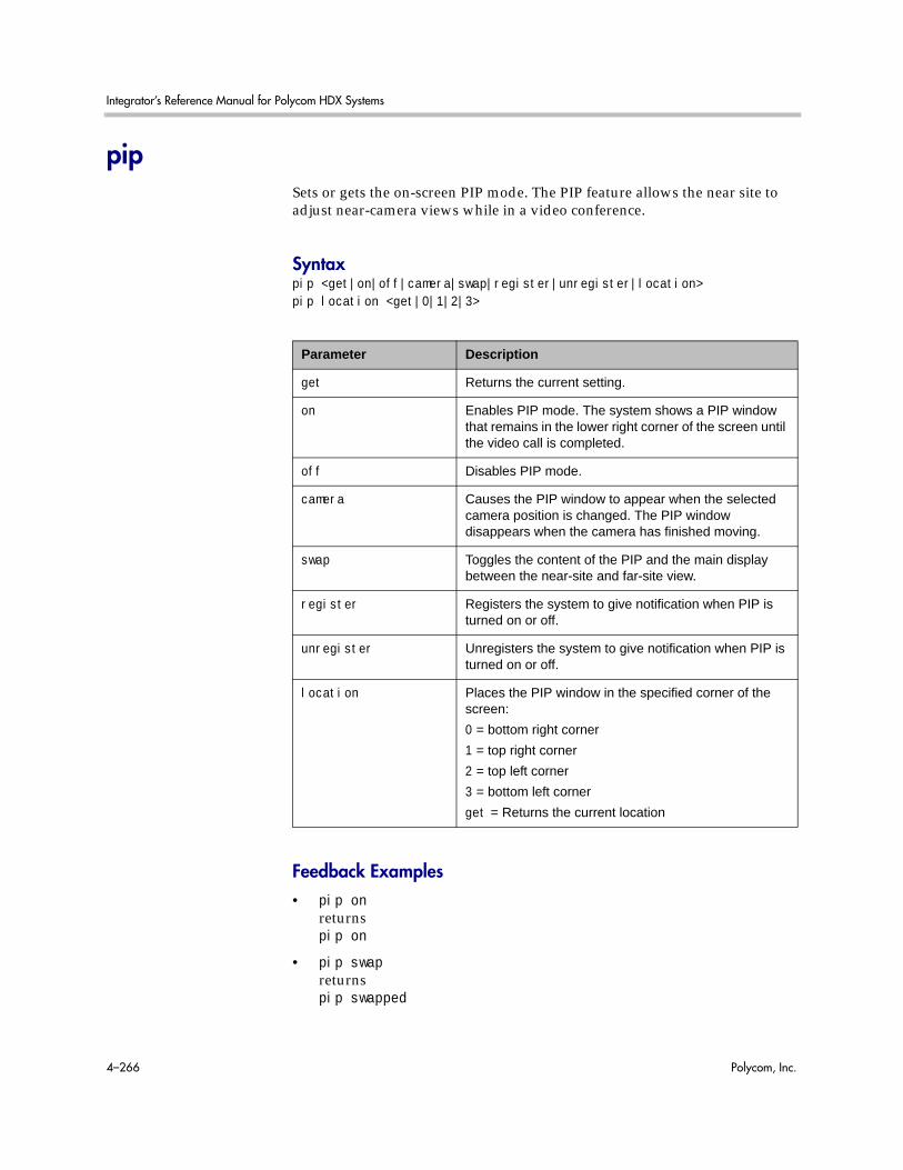
Integrator’s Reference Manual for Polycom HDX Systems
4–266 Polycom, Inc.
pipSets or gets the on-screen PIP mode. The PIP feature allows the near site to adjust near-camera views while in a video conference.
Syntaxpip <get|on|off|camera|swap|register|unregister|location>pip location <get|0|1|2|3>
Feedback Examples• pip on
returnspip on
• pip swapreturnspip swapped
Parameter Description
get Returns the current setting.
on Enables PIP mode. The system shows a PIP window that remains in the lower right corner of the screen until the video call is completed.
off Disables PIP mode.
camera Causes the PIP window to appear when the selected camera position is changed. The PIP window disappears when the camera has finished moving.
swap Toggles the content of the PIP and the main display between the near-site and far-site view.
register Registers the system to give notification when PIP is turned on or off.
unregister Unregisters the system to give notification when PIP is turned on or off.
location Places the PIP window in the specified corner of the screen:
0 = bottom right corner
1 = top right corner
2 = top left corner
3 = bottom left corner
get = Returns the current location

System Commands
Polycom, Inc. 4–267
• pip location getreturnspip location 1
• pip registerreturnspip registered

Integrator’s Reference Manual for Polycom HDX Systems
4–268 Polycom, Inc.
popupinfoRegisters or unregisters the session to receive popup text and button choices text.
Syntaxpopupinfo <get|register|unregister>
Feedback Examples• popupinfo register
returnspopupinfo registered
• popupinfo unregisterreturnspopupinfo unregistered
• popupinfo getreturnspopupinfo unregistered
The following examples show notifications that may be returned after registering to receive popup text and button choices text.
• popupinfo: question: Sorry. Cannot dial number because you are already in a call with the site.
• popupinfo: choice0: Ok is returned if a call fails
• popupinfo: question: Save Changes? popupinfo: choice0: Yes popupinfo: choice1: No popupinfo: answered: Yes is returned if the user edits the password field
Parameter Description
register Registers to receive popup information.
unregister Unregisters to receive popup information.
get Returns the current setting.
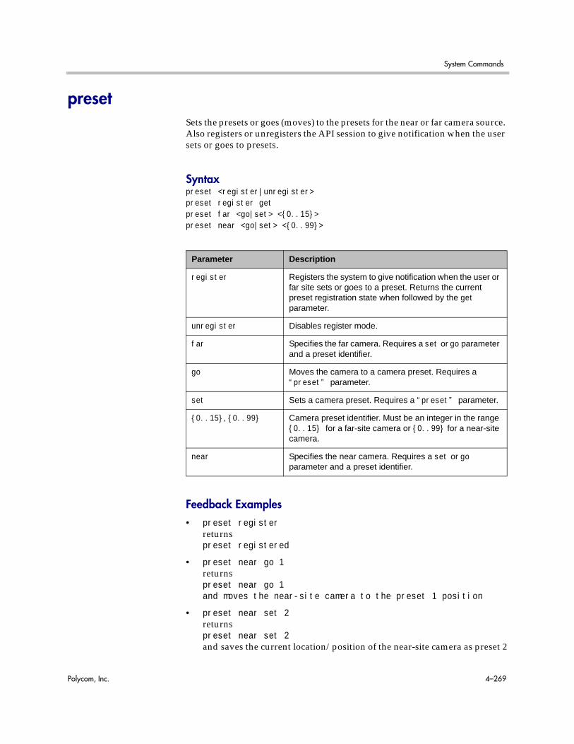
System Commands
Polycom, Inc. 4–269
presetSets the presets or goes (moves) to the presets for the near or far camera source. Also registers or unregisters the API session to give notification when the user sets or goes to presets.
Syntaxpreset <register|unregister>preset register getpreset far <go|set> <{0..15}>preset near <go|set> <{0..99}>
Feedback Examples• preset register
returnspreset registered
• preset near go 1returnspreset near go 1and moves the near-site camera to the preset 1 position
• preset near set 2returnspreset near set 2and saves the current location/position of the near-site camera as preset 2
Parameter Description
register Registers the system to give notification when the user or far site sets or goes to a preset. Returns the current preset registration state when followed by the get parameter.
unregister Disables register mode.
far Specifies the far camera. Requires a set or go parameter and a preset identifier.
go Moves the camera to a camera preset. Requires a “preset” parameter.
set Sets a camera preset. Requires a “preset” parameter.
{0..15}, {0..99} Camera preset identifier. Must be an integer in the range {0..15} for a far-site camera or {0..99} for a near-site camera.
near Specifies the near camera. Requires a set or go parameter and a preset identifier.

Integrator’s Reference Manual for Polycom HDX Systems
4–270 Polycom, Inc.
CommentsUp to 100 preset camera positions can be set. These camera presets can be distributed across the far camera and up to four near-site cameras.
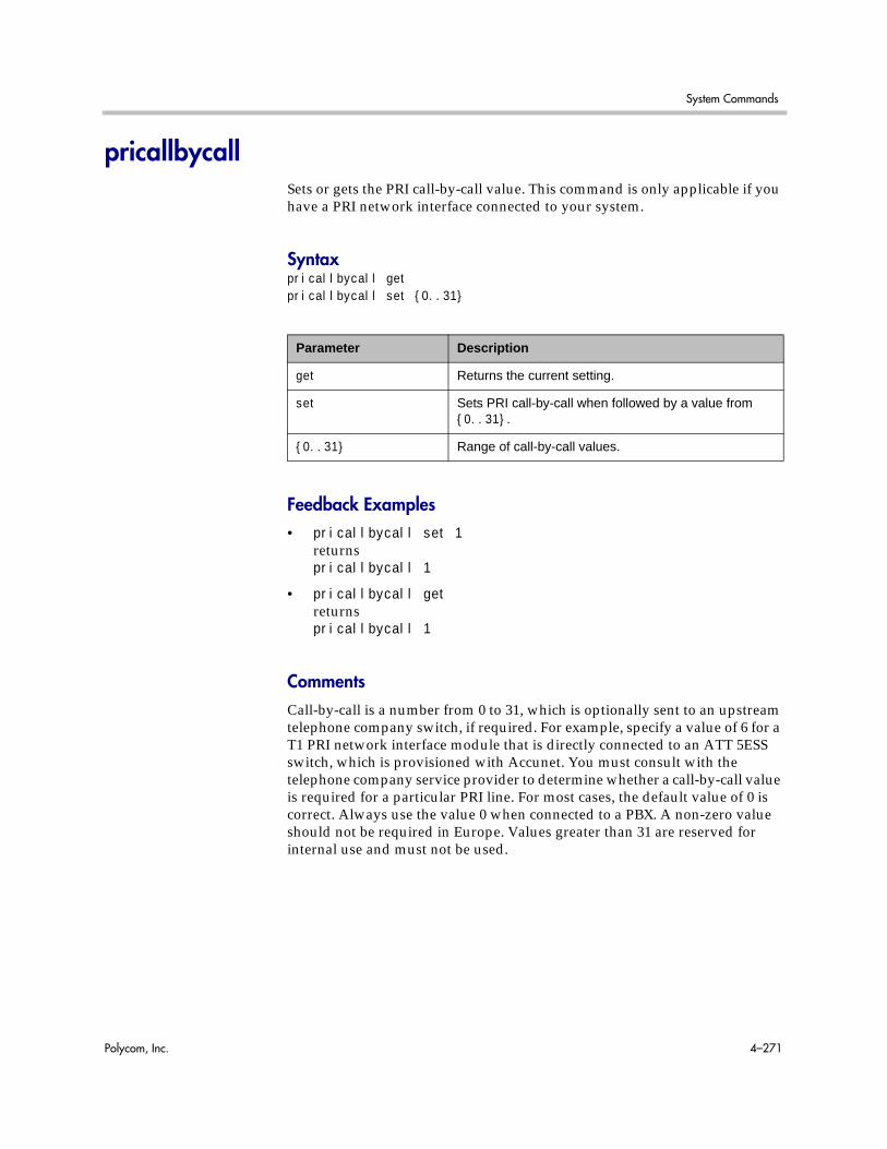
System Commands
Polycom, Inc. 4–271
pricallbycallSets or gets the PRI call-by-call value. This command is only applicable if you have a PRI network interface connected to your system.
Syntaxpricallbycall getpricallbycall set {0..31}
Feedback Examples• pricallbycall set 1
returnspricallbycall 1
• pricallbycall getreturnspricallbycall 1
CommentsCall-by-call is a number from 0 to 31, which is optionally sent to an upstream telephone company switch, if required. For example, specify a value of 6 for a T1 PRI network interface module that is directly connected to an ATT 5ESS switch, which is provisioned with Accunet. You must consult with the telephone company service provider to determine whether a call-by-call value is required for a particular PRI line. For most cases, the default value of 0 is correct. Always use the value 0 when connected to a PBX. A non-zero value should not be required in Europe. Values greater than 31 are reserved for internal use and must not be used.
Parameter Description
get Returns the current setting.
set Sets PRI call-by-call when followed by a value from {0..31}.
{0..31} Range of call-by-call values.
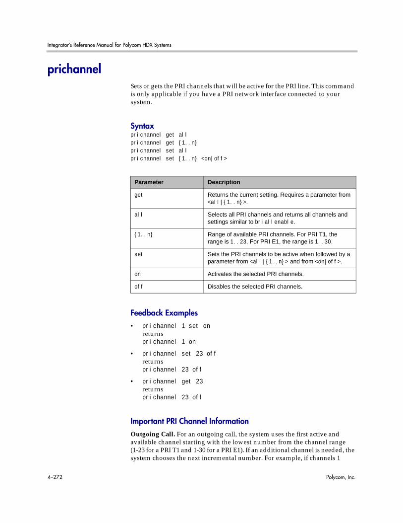
Integrator’s Reference Manual for Polycom HDX Systems
4–272 Polycom, Inc.
prichannelSets or gets the PRI channels that will be active for the PRI line. This command is only applicable if you have a PRI network interface connected to your system.
Syntaxprichannel get allprichannel get {1..n}prichannel set allprichannel set {1..n} <on|off>
Feedback Examples• prichannel 1 set on
returnsprichannel 1 on
• prichannel set 23 offreturnsprichannel 23 off
• prichannel get 23returnsprichannel 23 off
Important PRI Channel InformationOutgoing Call. For an outgoing call, the system uses the first active and available channel starting with the lowest number from the channel range (1-23 for a PRI T1 and 1-30 for a PRI E1). If an additional channel is needed, the system chooses the next incremental number. For example, if channels 1
Parameter Description
get Returns the current setting. Requires a parameter from <all|{1..n}>.
all Selects all PRI channels and returns all channels and settings similar to briallenable.
{1..n} Range of available PRI channels. For PRI T1, the range is 1..23. For PRI E1, the range is 1..30.
set Sets the PRI channels to be active when followed by a parameter from <all|{1..n}> and from <on|off>.
on Activates the selected PRI channels.
off Disables the selected PRI channels.

System Commands
Polycom, Inc. 4–273
through 7 are inactive, but 8 is active and available, then 8 is the first channel that can be used by the system to place an outgoing call. If an additional channel is needed, the system will use the next available active channel in the range (which could be 9, and so on).
Incoming Calls. For incoming calls, the system may use the highest numbered channel in the range and, if needed, proceed to the next channel number in descending order, depending on the type of third-party equipment attached to the system. For example, an incoming call arrives on channel 23, then 22, 21, and so on.
Dedicated full PRI T1 or E1 Line. All channels should be active for a full T1 or E1 line dedicated to your system.
Fractional PRI T1 or E1. Channel selection should be handled by your PRI network administrator.
PRI E1 Channel Information. The PRI Status screen (for E1) shows 30 channels. However, E1 trunk lines have 32 timeslots, numbered 0 - 31. Timeslot 0 is used for framing, and timeslot 16 is used for call signaling (the D channel). The remaining 30 timeslots are used as bearer (data) channels. In call signaling between our equipment and the switch, these channels are numbered 1-15, 17-31. But the PRI Status screen numbers these channels contiguously in the range 1-30. Therefore, on the PRI Status screen, channels 1-15 control the status of timeslots 1-15, and channels 16-30 control the status of timeslots 17-31.

Integrator’s Reference Manual for Polycom HDX Systems
4–274 Polycom, Inc.
pricsuSets or gets the PRI CSU mode for a T1 interface.
Syntaxpricsu <get|internal|external>
Feedback Examples• pricsu internal
returnspricsu internal
• pricsu externalreturnspricsu external
• pricsu getreturnspricsu external
CommentsBy default, the T1 PRI network interface module is set for internal CSU mode.
See AlsoThe PRI line buildout for a T1 interface is set using the prilinebuildout command on page 4-277.
Parameter Description
get Returns the current setting.
internal Sets the internal CSU mode. This is the default.
external Sets the external CSU mode. When selected, you must specify the PRI line buildout.

System Commands
Polycom, Inc. 4–275
pridialchannelsSets or gets the number of PRI channels to dial in parallel. This command is only applicable if you have a PRI network interface connected to your system.
Syntaxpridialchannels getpridialchannels set {1..n}
Feedback Examples• pridialchannels set 3
returnspridialchannels 3
• pridialchannels getreturnspridialchannels 3
CommentsBy default, ISDN channels are dialed three at a time. On PRI systems, you can choose the number of channels to dial in parallel.
Parameter Description
set Sets the number of PRI channels to be dialed in parallel when followed by a parameter from {1..n}. To erase the current setting, omit the parameter.
get Returns the current number of channels dialed in parallel.
{1..n} Range of numbers of PRI channels that can be dialed in parallel. For PRI T1, the range is 1..12. For PRI E1, the range is 1..15.

Integrator’s Reference Manual for Polycom HDX Systems
4–276 Polycom, Inc.
priintlprefixSets or gets the PRI international dialing prefix.
Syntaxpriintlprefix getpriintlprefix set ["prefix"]
Feedback Examples• priintlprefix set 011
returnspriintlprefix 011
• priintlprefix getreturnspriintlprefix 011
CommentsThe international prefix defaults to 011 for North America and 00 for European countries. The default depends on the country.
Parameter Description
get Returns the current setting.
set Sets the PRI international dialing prefix when followed by the parameter “prefix”. To erase the current setting, omit the parameter.
“prefix” Numeric string.
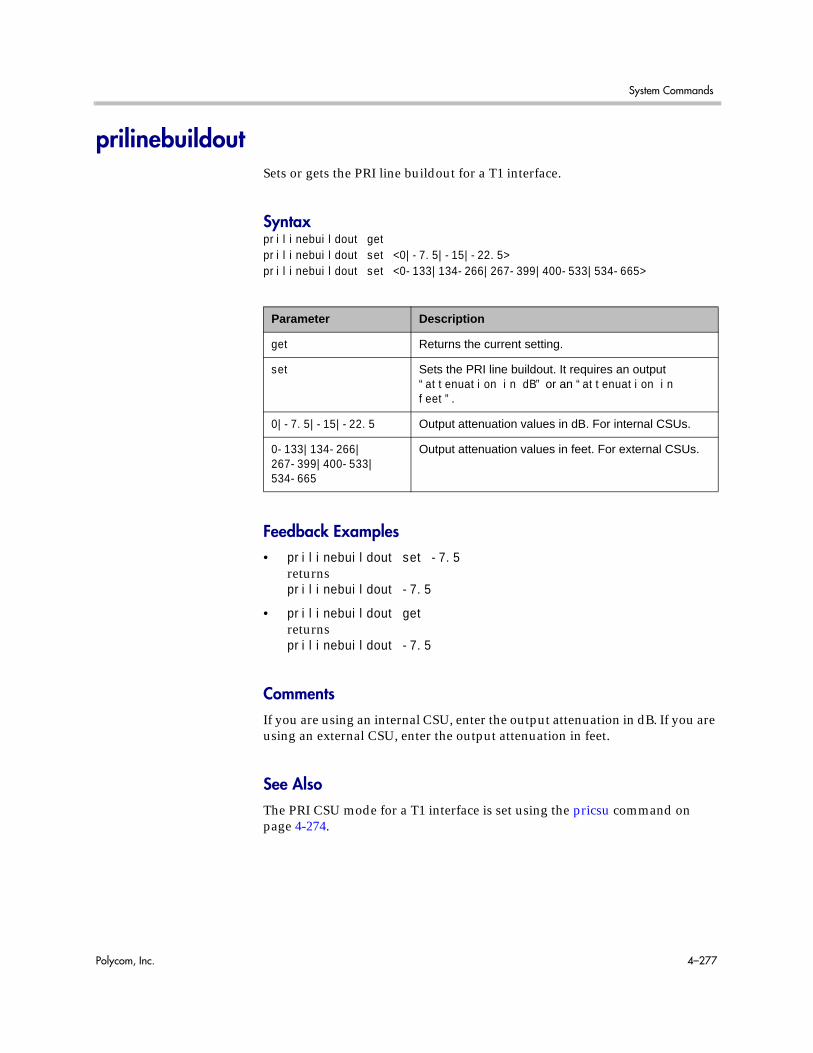
System Commands
Polycom, Inc. 4–277
prilinebuildoutSets or gets the PRI line buildout for a T1 interface.
Syntaxprilinebuildout getprilinebuildout set <0|-7.5|-15|-22.5>prilinebuildout set <0-133|134-266|267-399|400-533|534-665>
Feedback Examples• prilinebuildout set -7.5
returnsprilinebuildout -7.5
• prilinebuildout getreturnsprilinebuildout -7.5
CommentsIf you are using an internal CSU, enter the output attenuation in dB. If you are using an external CSU, enter the output attenuation in feet.
See AlsoThe PRI CSU mode for a T1 interface is set using the pricsu command on page 4-274.
Parameter Description
get Returns the current setting.
set Sets the PRI line buildout. It requires an output “attenuation in dB” or an “attenuation in feet”.
0|-7.5|-15|-22.5 Output attenuation values in dB. For internal CSUs.
0-133|134-266|267-399|400-533|534-665
Output attenuation values in feet. For external CSUs.
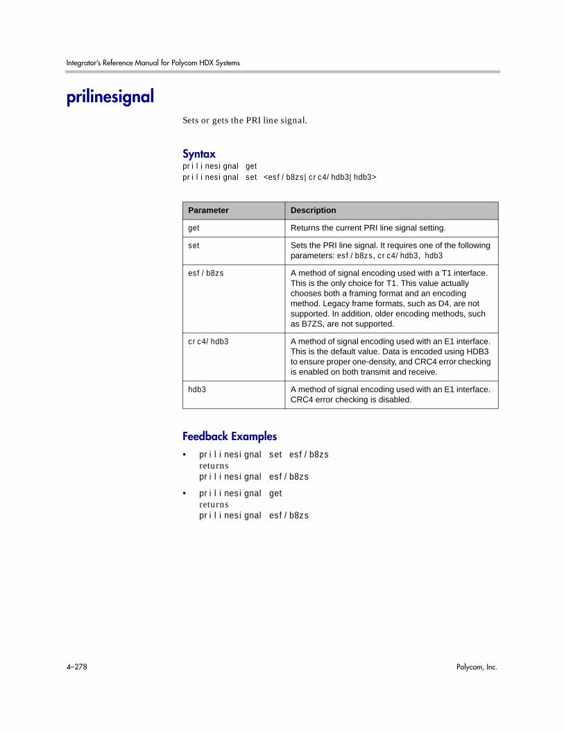
Integrator’s Reference Manual for Polycom HDX Systems
4–278 Polycom, Inc.
prilinesignalSets or gets the PRI line signal.
Syntaxprilinesignal getprilinesignal set <esf/b8zs|crc4/hdb3|hdb3>
Feedback Examples• prilinesignal set esf/b8zs
returnsprilinesignal esf/b8zs
• prilinesignal getreturnsprilinesignal esf/b8zs
Parameter Description
get Returns the current PRI line signal setting.
set Sets the PRI line signal. It requires one of the following parameters: esf/b8zs, crc4/hdb3, hdb3
esf/b8zs A method of signal encoding used with a T1 interface. This is the only choice for T1. This value actually chooses both a framing format and an encoding method. Legacy frame formats, such as D4, are not supported. In addition, older encoding methods, such as B7ZS, are not supported.
crc4/hdb3 A method of signal encoding used with an E1 interface. This is the default value. Data is encoded using HDB3 to ensure proper one-density, and CRC4 error checking is enabled on both transmit and receive.
hdb3 A method of signal encoding used with an E1 interface. CRC4 error checking is disabled.

System Commands
Polycom, Inc. 4–279
prinumberingplanSets or gets the PRI numbering plan. This command is only applicable if you have a PRI network interface connected to your system.
Syntaxprinumberingplan <get|isdn|unknown>
Feedback Examples• prinumberingplan isdn
returnsprinumberingplan isdn
• prinumberingplan unknownreturnsprinumberingplan unknown
• prinumberingplan getreturnsprinumberingplan unknown
Parameter Description
get Returns the current setting.
isdn With this parameter, the numbering plan is identified to the upstream switch as ISDN, and the number type, which is either national or international, is determined from the dialed phone number. If the dialed phone number starts with the international dialing prefix that is currently selected, the type is set to the international and the prefix is removed from the number before the number is sent to the upstream switch. Otherwise, the number is marked as national and passed to the upstream switch without modification.
unknown This is the default selection. With this parameter, the numbering plan and number type are sent to the upstream as unknown, and the dialed phone number is sent without notification. The unknown parameter is preferred and should work with all properly configured PBXs and with most telephone company switches. A notable exception in North America is an ATT 5ESS switch, which is provisioned with Accunet, or an ATT 4ESS switch. For these switches, set the numbering type to ISDN.

Integrator’s Reference Manual for Polycom HDX Systems
4–280 Polycom, Inc.
prioutsidelineSets or gets the PRI number that is dialed for outside line access.
Syntaxprioutsideline getprioutsideline set ["outside_line"]
Feedback Examples• prioutsideline set 9
returnsprioutsideline 9
• prioutsideline getreturnsprioutsideline 9
CommentsThis number is needed if your system is on a PBX.
Parameter Description
get Returns the current setting.
set Sets the outside-line-access PRI number when followed by the parameter “outside_line”. To erase the current setting, omit the parameter.
“outside_line” Numeric string. This number is provided by your network service provider.

System Commands
Polycom, Inc. 4–281
priswitchSets or gets the PRI switch.
Syntaxpriswitch getpriswitch set <att5ess|att4ess|norteldms|ni2>priswitch set <net5/ctr4|nttins-1500|ts-038>
Feedback Examples• priswitch set att5ess
returnspriswitch att5ess
• priswitch getreturnspriswitch att5ess
CommentsIf more than one switch protocol is supported, you must find out from your telephone service provider which protocol to select. NET5/CTR4 is the default. It is the standard ETSI protocol derived from ITU Q.931. If you change the country settings, a new set of PRI switch protocols is loaded.
Parameter Description
get Returns the current switch protocol.
set Sets the PRI switch. One of the switch protocol parameters is required.
att5ess|att4ess|norteldms|ni2|net5/ctr4|nttins-1500|ts-038
Switch protocol values.
For E1, net5/ctr4 is the default. net5/ctr4 is the standard ETSI protocol derived from ITU Q.931.
For T1, net5/ctr4 is also provided for certain Asian countries, such as Japan, Hong Kong, and Taiwan.

Integrator’s Reference Manual for Polycom HDX Systems
4–282 Polycom, Inc.
rebootRestarts the system.
Syntaxreboot [y|now|n]
Feedback Examples• reboot y
does not prompt the user to confirm and reboots the system with no other feedback returned
• reboot nowdoes not prompt the user to confirm and reboots the system with no other feedback returned
• reboot ndoes not reboot the system and returnsenter “reboot y” or “reboot now” to initiate system reboot
CommentsThe preferred format is reboot now.
Parameter Description
y Reboots the system without prompting you.
now Reboots the system without prompting you.
n Does not reboot the system.
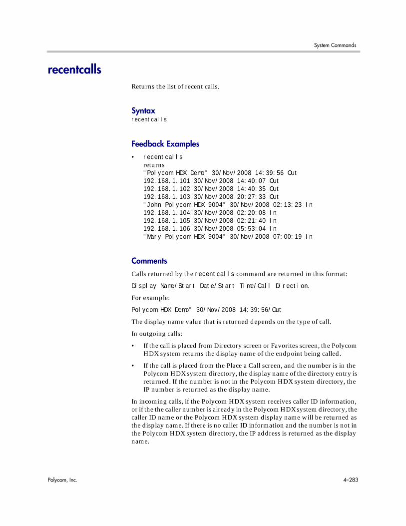
System Commands
Polycom, Inc. 4–283
recentcallsReturns the list of recent calls.
Syntaxrecentcalls
Feedback Examples• recentcalls
returns"Polycom HDX Demo" 30/Nov/2008 14:39:56 Out192.168.1.101 30/Nov/2008 14:40:07 Out192.168.1.102 30/Nov/2008 14:40:35 Out192.168.1.103 30/Nov/2008 20:27:33 Out"John Polycom HDX 9004" 30/Nov/2008 02:13:23 In192.168.1.104 30/Nov/2008 02:20:08 In192.168.1.105 30/Nov/2008 02:21:40 In192.168.1.106 30/Nov/2008 05:53:04 In"Mary Polycom HDX 9004" 30/Nov/2008 07:00:19 In
CommentsCalls returned by the recentcalls command are returned in this format:
Display Name/Start Date/Start Time/Call Direction.
For example:
Polycom HDX Demo" 30/Nov/2008 14:39:56/Out
The display name value that is returned depends on the type of call.
In outgoing calls:
• If the call is placed from Directory screen or Favorites screen, the Polycom HDX system returns the display name of the endpoint being called.
• If the call is placed from the Place a Call screen, and the number is in the Polycom HDX system directory, the display name of the directory entry is returned. If the number is not in the Polycom HDX system directory, the IP number is returned as the display name.
In incoming calls, if the Polycom HDX system receives caller ID information, or if the the caller number is already in the Polycom HDX system directory, the caller ID name or the Polycom HDX system display name will be returned as the display name. If there is no caller ID information and the number is not in the Polycom HDX system directory, the IP address is returned as the display name.

Integrator’s Reference Manual for Polycom HDX Systems
4–284 Polycom, Inc.
registerall (deprecated)Alias for the all register command.
Syntaxregisterall
Feedback Examplesregisterallreturnscallstate registeredcamera registeredchaircontrol registeredlinestate registeredmute registeredpip registeredpopup registeredpopupinfo registeredpreset registeredscreen registeredvcbutton registeredvolume registeredsleep registeredphone registeredvideo registeredvcstream registeredvc pod registeredvc lan registered
See AlsoThis command is an alias for the preferred all register command on page 4-19.
To unregister user feedback, use the all unregister command on page 4-21 or the unregisterall (deprecated) command on page 4-333.

System Commands
Polycom, Inc. 4–285
registerthissystemSets or gets the system’s IP address to be registered and displayed in the global directory when the system is powered on.
Syntaxregisterthissystem <get|yes|no>
Feedback Examples• registerthissystem yes
returnsregisterthissystem yes
• registerthissystem noreturnsregisterthissystem no
• registerthissystem getreturnsregisterthissystem no
CommentsIf you do not enable this option, the system has access to the GDS, but the IP address does not appear in the global directory.
Parameter Description
get Returns the current setting.
yes Enables this option (register this system).
no Disables this option.

Integrator’s Reference Manual for Polycom HDX Systems
4–286 Polycom, Inc.
remotecontrolSet or gets the setting for intercepting signals from the system remote control.
Syntaxremotecontrol disable <get|all|none>remotecontrol disable “valid button” [“valid button”...]remotecontrol dontintercept <all|none>remotecontrol dontintercept “valid button” [“valid button”...]remotecontrol enable <all|none>remotecontrol enable “valid button” [“valid button”...]
Feedback Examples• remotecontrol disable all
returnsremotecontrol disable all success
• remotecontrol disable getreturnsdisabled 1 buttons:pip
CommentsRemote control disable commands do not persist across the power cycle.
Parameter Description
disable Disables specified remote control button(s) so that the system does not respond.
get Returns the current setting.
all All of the remote control buttons.
none None of the remote control buttons.
“valid button” Name of a specific button such as call, hangup, left, right, up, down, select, home, directory, back, zoom-, zoom+, volume-, volume+, mute, far, near, auto, camera, preset, pip, keyboard, delete, ., 0-9, *, #, graphics, or help.
enable Enables specified remote control button(s).
power Enables or disables the Power button on the remote control.

System Commands
Polycom, Inc. 4–287
remotemonenableGets the state of remote room and call monitoring.
Syntaxremotemonenable <get>
Feedback Examples• remotemonenable get
returnsremotemonenable on
• remotemonenable getreturnsremotemonenable off

Integrator’s Reference Manual for Polycom HDX Systems
4–288 Polycom, Inc.
requireacctnumtodialEnables or disables the Require Account Number to Dial option. It is used to log calls to a specific account so that they can be tracked and billed to the appropriate departments.
Syntaxrequireacctnumtodial <get|yes|no>
Feedback Examples• requireacctnumtodial yes
returnsrequireacctnumtodial yes
• requireacctnumtodial noreturnsrequireacctnumtodial no
• requireacctnumtodial getreturnsrequireacctnumtodial no
CommentsWhen this option is selected, you cannot make a call without first entering an account number. This account number is saved in the Global Management System server database along with information specific to the call. Typically, the Global Management System administrator assigns the account number.
Parameter Description
get Returns the current setting.
yes Enables the option.
no Disables the option.
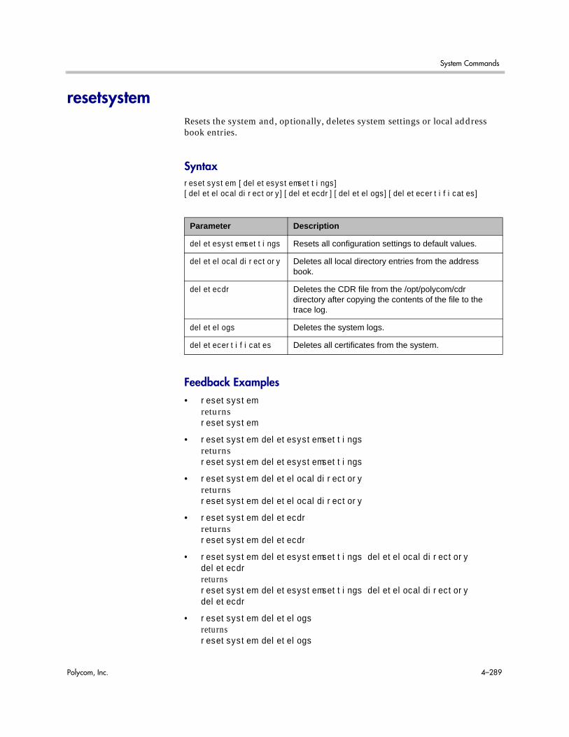
System Commands
Polycom, Inc. 4–289
resetsystemResets the system and, optionally, deletes system settings or local address book entries.
Syntaxresetsystem [deletesystemsettings] [deletelocaldirectory][deletecdr][deletelogs][deletecertificates]
Feedback Examples• resetsystem
returnsresetsystem
• resetsystem deletesystemsettingsreturnsresetsystem deletesystemsettings
• resetsystem deletelocaldirectoryreturnsresetsystem deletelocaldirectory
• resetsystem deletecdrreturnsresetsystem deletecdr
• resetsystem deletesystemsettings deletelocaldirectory deletecdrreturnsresetsystem deletesystemsettings deletelocaldirectory deletecdr
• resetsystem deletelogsreturnsresetsystem deletelogs
Parameter Description
deletesystemsettings Resets all configuration settings to default values.
deletelocaldirectory Deletes all local directory entries from the address book.
deletecdr Deletes the CDR file from the /opt/polycom/cdr directory after copying the contents of the file to the trace log.
deletelogs Deletes the system logs.
deletecertificates Deletes all certificates from the system.

Integrator’s Reference Manual for Polycom HDX Systems
4–290 Polycom, Inc.
• resetsystem deletecertificatesreturnsresetsystem deletecertificates

System Commands
Polycom, Inc. 4–291
roomphonenumberSets or gets the number of the phone that is located in the same room as the system.
Syntaxroomphonenumber getroomphonenumber set [“number”]
Feedback Examples• roomphonenumber set
returnsroomphonenumber <empty>
• roomphonenumber set “408 555 2323”returnsroomphonenumber 408.555.2323
• roomphonenumber getreturnsroomphonenumber 408.555.2323
CommentsIf the system is managed by the Global Management System software, this number will be provided to the Global Management System administrator if the person using the system requests help.
Parameter Description
get Returns the current setting.
set Sets the room phone number when followed by the “number” parameter. To erase the current setting, omit the “number” parameter.
“number” Phone number for a telephone (not the system) in the room. Use quotation marks around the number if it contains spaces. For example: “408 555 2323”
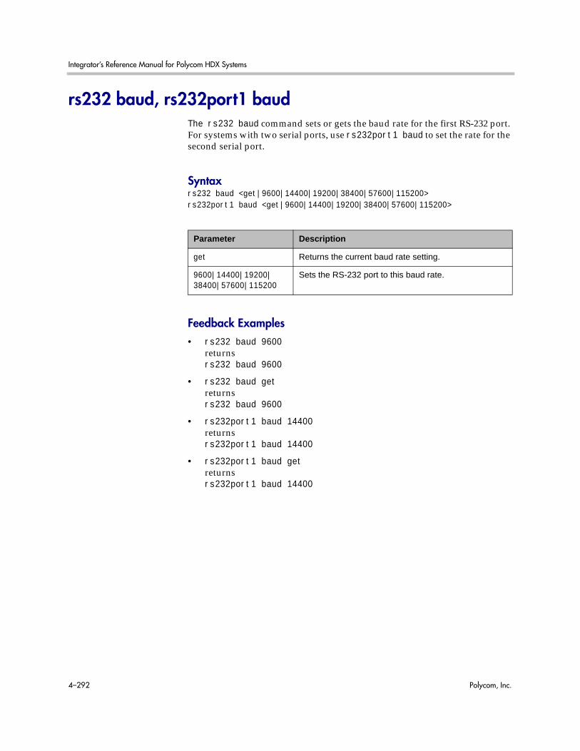
Integrator’s Reference Manual for Polycom HDX Systems
4–292 Polycom, Inc.
rs232 baud, rs232port1 baudThe rs232 baud command sets or gets the baud rate for the first RS-232 port. For systems with two serial ports, use rs232port1 baud to set the rate for the second serial port.
Syntaxrs232 baud <get|9600|14400|19200|38400|57600|115200>rs232port1 baud <get|9600|14400|19200|38400|57600|115200>
Feedback Examples• rs232 baud 9600
returnsrs232 baud 9600
• rs232 baud getreturnsrs232 baud 9600
• rs232port1 baud 14400returnsrs232port1 baud 14400
• rs232port1 baud getreturnsrs232port1 baud 14400
Parameter Description
get Returns the current baud rate setting.
9600|14400|19200| 38400|57600|115200
Sets the RS-232 port to this baud rate.

System Commands
Polycom, Inc. 4–293
rs232 mode, rs232port1 modeThe rs232 mode command sets or gets the operational mode of the first RS-232 port. For systems with two serial ports, use rs232port1 mode to set the mode for the second serial port.
Syntaxrs232 mode <get|passthru|control|debug|camera_ptz|closed_caption|vortex_mixer|cps|interactive_touch_board|polycom_annotation|smartboard|pointmaker>rs232port1 mode <get|passthru|control|debug|camera_ptz|closed_caption|vortex_mixer|cps|interactive_touch_board|polycom_annotation|smartboard|pointmaker>
Feedback Examples• rs232 mode control
returnsrs232 mode control
• rs232port1 mode closed_captionreturnsrs232port1 mode closed_caption
Parameter Description
get Returns the current mode setting.
passthru Sets the RS-232 port to Pass Thru mode.
contol Sets the RS-232 port to Control mode.
debug Sets the RS-232 port to Debug mode.
camera_ptz Sets the RS-232 port to Camera PTZ mode.
closed_caption Sets the RS-232 port to Closed Caption mode.
vortex_mixer Sets the RS-232 port to Vortex Mixer mode.
interactive_touch_board
Sets the RS-232 port to Interactive Touch Board mode.
smartboard Sets the RS-232 port to Interactive Touch Board mode (to control a Polycom SMART board device).
polycom_annotation Sets the RS-232 port to Polycom Annotation mode.
cps|pointmaker Reserved for future applications.

Integrator’s Reference Manual for Polycom HDX Systems
4–294 Polycom, Inc.
• rs232port1 mode getreturnsrs232port1 mode closed_caption
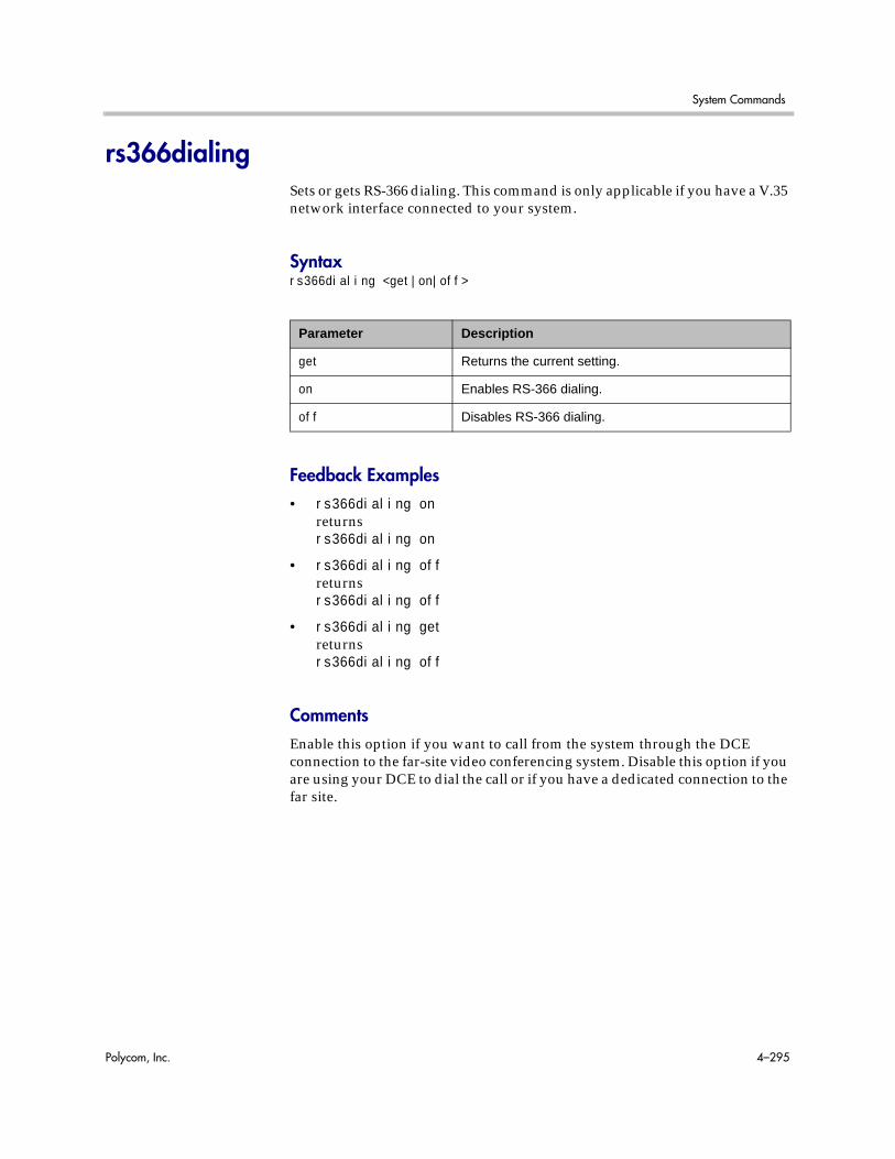
System Commands
Polycom, Inc. 4–295
rs366dialingSets or gets RS-366 dialing. This command is only applicable if you have a V.35 network interface connected to your system.
Syntaxrs366dialing <get|on|off>
Feedback Examples• rs366dialing on
returnsrs366dialing on
• rs366dialing offreturnsrs366dialing off
• rs366dialing getreturnsrs366dialing off
CommentsEnable this option if you want to call from the system through the DCE connection to the far-site video conferencing system. Disable this option if you are using your DCE to dial the call or if you have a dedicated connection to the far site.
Parameter Description
get Returns the current setting.
on Enables RS-366 dialing.
off Disables RS-366 dialing.

Integrator’s Reference Manual for Polycom HDX Systems
4–296 Polycom, Inc.
rtSets or gets the RT serial interface control signal (receive timing: clock). This command is only applicable if you have a V.35 network interface connected to your system.
Syntaxrt <get|normal|inverted>
Feedback Examples• rt normal
returnsrt normal
• rt invertedreturnsrt inverted
• rt getreturnsrt inverted
CommentsThe default setting is normal.
Parameter Description
get Returns the current setting.
normal Sets the signal to normal (rising edge receives data).
inverted Sets the signal to inverted (falling edge receives data).

System Commands
Polycom, Inc. 4–297
rtsSets or gets the RTS serial interface control signal (request to send). This command is only applicable if you have a V.35 network interface connected to your system.
Syntaxrts <get|normal|inverted>
Feedback Examples• rts normal
returnsrts normal
• rts invertedreturnsrts inverted
• rts getreturnsrts inverted
CommentsThe default setting is “normal”.
Parameter Description
get Returns the current setting.
normal Sets the signal to normal (high voltage is logic 1).
inverted Sets the signal to inverted (low voltage is logic 1).

Integrator’s Reference Manual for Polycom HDX Systems
4–298 Polycom, Inc.
screenReturns the name of the current user interface screen on the system, registers or unregisters for screen changes, or goes to a specific user interface screen.
Syntaxscreenscreen register getscreen [register|unregister]screen “screen_name”
Feedback Examples• screen
returnsscreen: adminsettingsif the Admin Settings screen is currently displayed in the user interface
• screen registerreturnsscreen registered
• screen monitorsreturnsscreen: monitorsand displays the Monitors screen in the user interface
Parameter Description
screen Returns the name of the current user interface screen if not followed by other parameters.
register Registers for user interface screen changes. In register mode, the name of every screen accessed is listed.
get Returns the registration state for screen change events when followed by the get parameter.
unregister Unregisters from user interface screen changes.
“screen_name” Changes the user interface to display the specified screen. The supported screens depend on the system configuration. To determine the name to use for a specific screen, navigate to that screen in the user interface and send the screen command.

System Commands
Polycom, Inc. 4–299
screencontrolDisables or enables navigation to specified user interface screens of the system.
Syntaxscreencontrol enable <all|none|“screen_name”>screencontrol disable <all|none|“screen_name”>
Feedback Examples• screencontrol enable all
returnsscreencontrol enable all success
• screencontrol disable adminsettingsreturnsscreencontrol disable adminsettings successand disables navigation to the Admin Settings screen of the user interface
• screencontrol disable nonereturnsscreencontrol disable none successand reverses all screen disable commands
• screencontrol disable mainreturnserror: screen “main” unknownscreencontrol disable main failedif “main” is an unknown screen name
See AlsoRefer to the screen command on page 4-298 for details about accessing screen names.
Parameter Description
enable Enables navigation to the specified user interface screen(s).
all All of the user interface screens.
none None of the user interface screens.
“screen_name” Name of a specific user interface screen.
disable Disables navigation to the specified user interface screen(s).

Integrator’s Reference Manual for Polycom HDX Systems
4–300 Polycom, Inc.
serialnumReturns the serial number of the system.
Syntaxserialnum
Feedback Examples• serialnum
returnsserialnum 82065205E72EC1

System Commands
Polycom, Inc. 4–301
servervalidatepeercertEnables certificate validation by specifying whether the HDX system requires a browser to present a valid certificate when it tries to connect to the HDX web interface.
Syntaxservervalidatepeercert getservervalidatepeercert <yes|no>
Feedback Examples• servervalidatepeercert get
returnsservervalidatepeercert no
• servervalidatepeercert yesreturnsservervalidatepeercert yes
CommentsAfter making a change, you must restart the system for the setting to take effect.
Parameter Description
get Returns the peer certificate validation setting for web servers.
yes Enables peer certificate validation requirement for web servers.
no Disables peer certificate validation requirement for web servers.
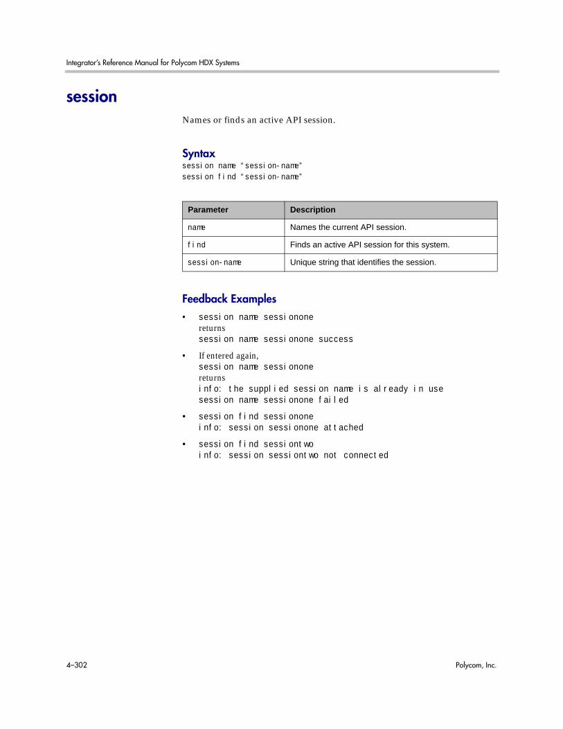
Integrator’s Reference Manual for Polycom HDX Systems
4–302 Polycom, Inc.
sessionNames or finds an active API session.
Syntaxsession name “session-name”session find “session-name”
Feedback Examples• session name sessionone
returnssession name sessionone success
• If entered again,session name sessiononereturnsinfo: the supplied session name is already in usesession name sessionone failed
• session find sessiononeinfo: session sessionone attached
• session find sessiontwoinfo: session sessiontwo not connected
Parameter Description
name Names the current API session.
find Finds an active API session for this system.
session-name Unique string that identifies the session.

System Commands
Polycom, Inc. 4–303
sessionsenabledSets or gets the ability to monitor for and terminate inactive Polycom HDX web sessions.
Syntaxsessionsenabled getsessionsenabled <yes|no>
Feedback Examples• sessionsenabled get
returnssessionsenabled yes
• sessionsenabled yesreturnssessionsenabled yes
CommentsWhen sessionsenabled is set to yes, and a web session is started, the user must log in to each subsequent web request during the session.
Parameter Description
get Returns the current setting for web sessions monitoring.
yes Enables web session monitoring.
no Disables web session monitoring.

Integrator’s Reference Manual for Polycom HDX Systems
4–304 Polycom, Inc.
setaccountnumberSets the account number when it is required for dialing out.
Syntaxsetaccountnumber “account number”
Feedback Examples• setaccountnumber 1234
returnssetaccountnumber 1234
CommentsThe account number is saved in the Global Management System database and is generally assigned by the Global Management System administrator. The requireacctnumtodial command on page 4-288 and the validateacctnum command on page 4-347 must be enabled for this command to work. When you make a call, you will be prompted to enter your account number.
See AlsoSee the related requireacctnumtodial command on page 4-288 and validateacctnum command on page 4-347.
Parameter Description
“account number” Number that is needed to validate the account before dialing out. To erase the current setting, omit this parameter.

System Commands
Polycom, Inc. 4–305
setpasswordSets the admin password for the Polycom HDX system local admin account.
Syntaxsetpassword admin room "currentacctpasswd" "newacctpasswd"
Feedback Examples• setpassword admin room 123 456
returnspassword changed
• setpassword admin room ‘’ 456returnspassword changed
• setpassword admin room 123 ‘’returnspassword changed
CommentsIf the account has no administrator room password, enter a pair of single quotes ('') to denote an empty password.
Parameter Description
admin Specifies the Polycom HDX system local admin account.
room Changes the room password.
“currentacctpasswd” The current account password.
“newacctpasswd” The new account password.

Integrator’s Reference Manual for Polycom HDX Systems
4–306 Polycom, Inc.
showpopupDisplays a message box in the user interface.
Syntaxshowpopup “text to display”
Feedback Examples• showpopup “The conference will resume in three minutes.”
returnsshowpopup “The conference will resume in three minutes.”and displays the message box in the user interface
CommentsSending this command displays the message as a popup dialog in the user interface, along with an alert tone.
Parameter Description
“text to display” Message to display to users. Enclose the text in quotation marks if it contains a space.

System Commands
Polycom, Inc. 4–307
sleepPuts the system in sleep mode within 15 seconds and returns sleep.
Syntaxsleepsleep <register|unregister>
Feedback Examples• sleep
returnssleepand puts the system in sleep mode within 15 seconds
• sleep registerreturnssleep registered
• If entered again,sleep registerreturnsinfo: event/notification already active:sleep
• sleep unregisterreturnssleep unregistered
• If entered again,sleep unregisterreturnsinfo: event/notification not active:sleep
See AlsoTo wake the system from sleep mode, use the wake command on page 4-362.
Parameter Description
sleep Puts the system in sleep mode if not followed by other parameters.
register Registers for sleep or wake events.
unregister Unregisters from sleep or wake events.

Integrator’s Reference Manual for Polycom HDX Systems
4–308 Polycom, Inc.
sleeptextSets or gets the text to be displayed with the logo for 15 seconds as the system goes into sleep mode.
Syntaxsleeptext getsleeptext set [“text”]
Feedback Examples• sleeptext set
returnssleeptext <empty>
• sleeptext set "Pick up the remote control to use the system"returnssleeptext "Pick up the remote control to use the system"
Parameter Description
get Returns the current text.
set Sets the text to be displayed on the screen saver when followed by the “text” parameter. To erase the current setting, omit “text”.
“text” Screen saver text to be displayed when the system is in sleep mode. Enclose the text in quotation marks if it includes spaces.

System Commands
Polycom, Inc. 4–309
sleeptimeSets or gets the wait time value before the system goes to sleep and displays the screen saver.
Syntaxsleeptime <get|0|1|3|15|30|60|120|240|480>
Feedback Examples• sleeptime 30
returnssleeptime 30
Parameter Description
get Returns the current setting.
0|1|3|15|30|60|120|240|480
Sets the number of minutes from last user interaction to entering sleep mode. The default value is 3. A value of 0 indicates that the system will never go to sleep.

Integrator’s Reference Manual for Polycom HDX Systems
4–310 Polycom, Inc.
snmpadminSets or gets the SNMP administrator name.
Syntaxsnmpadmin getsnmpadmin set ["admin name"]
Feedback Examples• snmpadmin set
returnserror: command needs more parameters to execute successfully
• snmpadmin set “John Admin”returnssnmpadmin “John Admin”
• snmpadmin getreturnssnmpadmin “John Admin”
CommentsAfter making a change, you must restart the system for the setting to take effect.
Parameter Description
get Returns the current setting.
set Sets the administrator name when followed by the “admin name” parameter. To erase the current setting, omit “admin name”.
“admin name” SNMP administrator contact name. Character string. Enclose the character string in quotation marks if it includes spaces. Example: “John Admin”
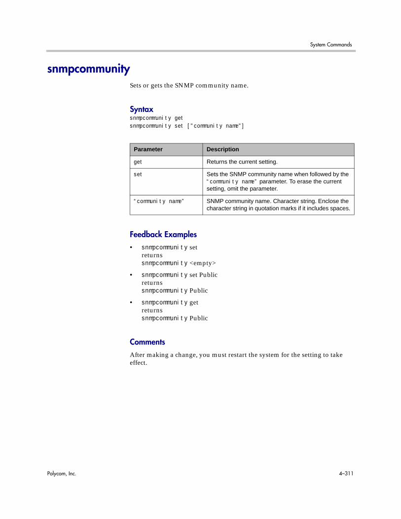
System Commands
Polycom, Inc. 4–311
snmpcommunitySets or gets the SNMP community name.
Syntaxsnmpcommunity getsnmpcommunity set ["community name"]
Feedback Examples• snmpcommunity set
returnssnmpcommunity <empty>
• snmpcommunity set Publicreturnssnmpcommunity Public
• snmpcommunity getreturnssnmpcommunity Public
CommentsAfter making a change, you must restart the system for the setting to take effect.
Parameter Description
get Returns the current setting.
set Sets the SNMP community name when followed by the “community name” parameter. To erase the current setting, omit the parameter.
“community name” SNMP community name. Character string. Enclose the character string in quotation marks if it includes spaces.

Integrator’s Reference Manual for Polycom HDX Systems
4–312 Polycom, Inc.
snmpconsoleipSets or gets the SNMP console IP address.
Syntaxsnmpconsoleip getsnmpconsoleip set ["xxx.xxx.xxx.xxx"]
Feedback Examples• snmpconsoleip set
returnssnmpconsoleip <empty>
• snmpconsoleip set 192.168.1.111returnssnmpconsoleip 192.168.1.111
• snmpconsoleip get 192.168.1.111returnssnmpconsoleip 192.168.1.111
CommentsAfter making a change, you must restart the system for the setting to take effect.
Parameter Description
get Returns the current setting.
set Sets the SNMP console IP address when followed by the “xxx.xxx.xxx.xxx” parameter. To erase the current setting, omit the parameter.
“xxx.xxx.xxx.xxx” IP address of the console.

System Commands
Polycom, Inc. 4–313
snmplocationSets or gets the SNMP location name.
Syntaxsnmplocation getsnmplocation ["location name"]
Feedback Examples• snmplocation
returnssnmplocation <empty>
• snmplocation “Mary_Polycom in United States”returnssnmplocation “Mary_Polycom in United States”
• snmplocation getreturnssnmplocation “Mary_Polycom in United States”
CommentsAfter making a change, you must restart the system for the setting to take effect.
Parameter Description
get Returns the current setting.
“location name” SNMP location name. Enclose the location name in quotation marks if it includes spaces. To erase the current setting, omit the parameter.

Integrator’s Reference Manual for Polycom HDX Systems
4–314 Polycom, Inc.
snmpsystemdescriptionSets or gets the SNMP system description.
Syntaxsnmpsystemdescription getsnmpsystemdescription set ["system description"]
Feedback Examples• snmpsystemdescription set
returnssnmpsystemdescription <empty>
• snmpsystemdescription set “videoconferencing system”returnssnmpsystemdescription “videoconferencing system”
• snmpsystemdescription getreturnssnmpsystemdescription “videoconferencing system”
CommentsAfter making a change, you must restart the system for the setting to take effect.
Parameter Description
get Returns the current setting.
set Sets the SNMP system description when followed by the “system description” parameter. To erase the current setting, omit the parameter.
“system description” SNMP system description.

System Commands
Polycom, Inc. 4–315
snmptrapversionSets or gets the SNMP trap version.
Syntaxsnmptrapversion getsnmptrapversion set <v1|v2c>
Feedback Examples• snmptrapversion set v1
returnssnmptrapversion v1
• snmptrapversion set v2creturnssnmptrapversion v2c
• snmptrapversion getreturnssnmptrapversion v2c
CommentsAfter making a change, you must restart the system for the setting to take effect.
Parameter Description
get Returns the current setting.
set Sets the SNMP trap protocol that the system uses.
v1|v2c SNMP trap version 1 or version 2c.

Integrator’s Reference Manual for Polycom HDX Systems
4–316 Polycom, Inc.
soundeffectsvolumeSets, gets, or tests the volume level of the ring tone and user alert tone on the system.
Syntaxsoundeffectsvolume getsoundeffectsvolume set {0..10}soundeffectsvolume test
Feedback Examples• soundeffectsvolume set 6
returnssoundeffectsvolume 6
• soundeffectsvolume getreturnssoundeffectsvolume 6
• soundeffectsvolume testreturnssoundeffectsvolume testand a tone is produced by the system
Parameter Description
get Returns the current setting along with a test tone from the system at that volume level.
set Sets the volume of sound effects. Requires a volume parameter in the range {0..10}.
test Tests the volume of sound effects.

System Commands
Polycom, Inc. 4–317
spidnumSets or gets the ISDN SPID numbers assigned to the BRI lines used by the system. This command is only applicable if you have a BRI network interface connected to your system.
Syntaxspidnum get <all|1b1|1b2|2b1|2b2|3b1|3b2|4b1|4b2>spidnum set <1b1|1b2|2b1|2b2|3b1|3b2|4b1|4b2> [“spid number”]
Feedback Examples• spidnum get all
returnsspidnum 1b1 7005551212spidnum 1b2 7005552323spidnum 2b1 7005553434spidnum 2b2 7005554545spidnum 3b1 7005555656spidnum 3b2 7005556767spidnum 4b1 7005557878spidnum 4b2 7005558989if 4 lines with channels 1b1 through 4b2 are attached in the above format.
Parameter Description
get Returns the current SPID number associated with a B channel of a particular line.
all Returns SPIDs for all channels of all lines.
1b1|1b2|2b1|2b2|3b1|3b2|4b1|4b2
The line and B channel. Valid values are:
1b1BRI line 1, B channel 1
1b2BRI line 1, B channel 2
2b1BRI line 2, B channel 1
2b2BRI line 2, B channel 2
3b1BRI line 3, B channel 1
3b2BRI line 3, B channel 2
4b1BRI line 4, B channel 1
4b2BRI line 4, B channel 2
set Sets the SPID number for a B channel line when followed by the “number” parameter. To erase the current setting, omit “number”. This paramater is not allowed while in a call.
“spid number” Numeric string. SPID numbers are generally provided by your network service provider.

Integrator’s Reference Manual for Polycom HDX Systems
4–318 Polycom, Inc.
• spidnum set 1b1returnsspidnum 1b1 <empty>
• spidnum set 1b1 7005551212returnsspidnum 1b1 7005551212
CommentsSPIDs generally apply only in the United States and Canada. If you are behind an internal phone system (PBX), SPIDs may not be required.

System Commands
Polycom, Inc. 4–319
stSets or gets the st serial interface control signal (send timing: clock) setting. This command is only applicable if you have a V.35 network interface connected to your system.
Syntaxst <get|normal|inverted>
Feedback Examples• st normal
returnsst normal
• st invertedreturnsst inverted
• st getreturnsst inverted
CommentsThe default setting is “normal”.
Parameter Description
get Returns the current setting.
normal Sets the signal to normal (falling edge sends data).
inverted Sets the signal to inverted (rising edge sends data).

Integrator’s Reference Manual for Polycom HDX Systems
4–320 Polycom, Inc.
sslverificationdepthSpecifies how many links a certificate chain can have.
Syntaxsslverificationdepth getsslverificationdepth set {0..12}
Feedback Examples• sslverificationdepth get
returnssslverificationdepth 3
• sslverificationdepth set 5returnssslverificationdepth 5
CommentsAfter making a change, you must restart the system for the setting to take effect.
Parameter Description
get Returns the current setting.
set {0..12} Sets the number of links a certificate chain can have. Valid values are {0..12}.
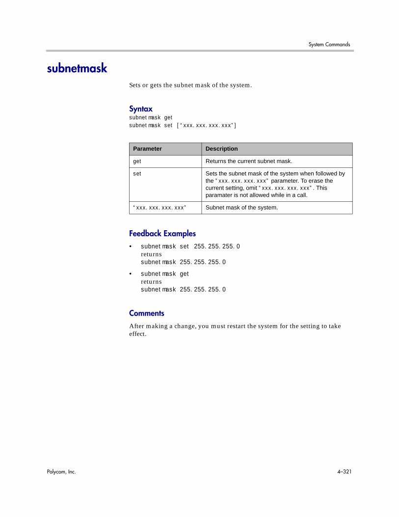
System Commands
Polycom, Inc. 4–321
subnetmaskSets or gets the subnet mask of the system.
Syntaxsubnetmask getsubnetmask set [“xxx.xxx.xxx.xxx”]
Feedback Examples• subnetmask set 255.255.255.0
returnssubnetmask 255.255.255.0
• subnetmask getreturnssubnetmask 255.255.255.0
CommentsAfter making a change, you must restart the system for the setting to take effect.
Parameter Description
get Returns the current subnet mask.
set Sets the subnet mask of the system when followed by the ”xxx.xxx.xxx.xxx” parameter. To erase the current setting, omit “xxx.xxx.xxx.xxx”. This paramater is not allowed while in a call.
“xxx.xxx.xxx.xxx” Subnet mask of the system.

Integrator’s Reference Manual for Polycom HDX Systems
4–322 Polycom, Inc.
sysinfoSets or gets registration for ISDN, IP, and gatekeeper status notifications.
Syntaxsysinfo <get|register|unregister>
Feedback Examples• sysinfo register
returnssysinfo registered
• sysinfo unregisterreturnssysinfo unregistered
• sysinfo getreturnssysinfo unregistered
The following are examples of notifications of status changes in ISDN lines that may be returned after registering to receive sysinfo notifications.
• linestate: isdnline[1] down
• linestate: isdnline[2] down
• linestate: isdnline[3] up
• linestate: isdnline[4] up
• linestate: isdnline[1] up
• linestate: isdnline[3] down
• linestate: isdnline[4] down
• linestate: isdnline[2] up
Parameter Description
get Returns registration status.
register Registers the shell session to receive ISDN, IP, and gatekeeper status notifications.
unregister Unregisters the shell session for ISDN, IP, and gatekeeper status notifications.

System Commands
Polycom, Inc. 4–323
systemnameSets or gets the name of the system.
Syntaxsystemname getsystemname set “system name”
Feedback Examples• systemname set “Polycom HDX Demo”
returnssystemname “Polycom HDX Demo”
• systemname set getreturnssystemname “Polycom HDX Demo”
CommentsThe first character must be a numeric (a digit) or alphabetic (a letter) character including foreign language characters. The name can be any combination of alphanumeric characters and may be up to 30 characters in length. The system name cannot be blank.
Parameter Description
get Returns the current setting.
set Sets the system name to “system name”.
“system name” Character string specifying the system name. Enclose the string in quotation marks if it includes spaces. Example: “Polycom HDX Demo”

Integrator’s Reference Manual for Polycom HDX Systems
4–324 Polycom, Inc.
systemsetting telnetenabledSets or gets the telnet ports.
Syntaxsystemsetting get telnetenabledsystemsetting telnetenabled <on|off|port24only>
Feedback Examples• systemsetting telnetenabled on
returnssystemsetting telnetenabled on
• systemsetting get telnetenabledreturnssystemsetting telnetenabled on
CommentsAfter making a change, you must restart the system for the setting to take effect.
If a security profile is enabled on the system, you cannot activate telnet ports.
Parameter Description
get Returns the current setting.
on Enables port 23 and port 24.
off Disables port 23 and port 24.
port24only Enables port 24 and disables port 23.

System Commands
Polycom, Inc. 4–325
tcpportsSets or gets the TCP ports on the system.
Syntaxtcpports gettcpports set [{1024..49150}]
Feedback Examples• tcpports set 3233
returnstcpports 3233
• tcpports getreturnstcpports 3233
CommentsThe Fixed Ports option on the Firewall screen must be selected for the TCP Ports option to be available.
Parameter Description
set Sets the TCP ports when followed by a value from the range {1024..49150}. To erase the current setting, omit the value. This paramater is not allowed while in a call.
get Returns the current TCP port setting.

Integrator’s Reference Manual for Polycom HDX Systems
4–326 Polycom, Inc.
techsupportSends your phone number to Global Management System technical support if your system is managed by the Global Management System.
Syntaxtechsupport <"phone num">
Feedback Examples• techsupport “408 555 2323”
returnstechsupport will contact you at 408 555 2323
CommentsThe Support icon is visible only when the system is registered with the Polycom Global Management System.
Parameter Description
“phone num” Phone number at which the user of this system will be contacted. To obtain rapid assistance, include the area code with the phone number. Enclose the string in quotation marks if it includes spaces. Example: “408 555 2323”

System Commands
Polycom, Inc. 4–327
teleareacodeSets or gets the system’s area code.
Syntaxteleareacode getteleareacode set ["telephone_area_code"]
Feedback Examples• teleareacode set
returnsteleareacode <empty>
• teleareacode set 408returnsteleareacode 408
• teleareacode getreturnsteleareacode 408
Parameter Description
get Returns the current setting.
set Sets the system’s area code when followed by the “telephone_area_code” parameter. To erase the current setting, omit the “telephone_area_code” parameter.
“telephone_area_code” System’s area code.

Integrator’s Reference Manual for Polycom HDX Systems
4–328 Polycom, Inc.
telenumberSets or gets the system’s telephone number.
Syntaxtelenumber gettelenumber set ["telephone_number"]
Feedback Examples• telenumber set
returnstelenumber <empty>
• telenumber set “408 555 2323”returnstelenumber “408 555 2323”
• telenumber getreturnstelenumber “408 555 2323”
Parameter Description
get Returns the current setting.
set Sets the telephone number when followed by the “telephone number” parameter. To erase the current setting, omit the parameter.
“telephone_number” System’s telephone number. Enclose the string in quotation marks if it includes spaces. Example: “408 555 2323”

System Commands
Polycom, Inc. 4–329
telnetechoeolSets the echo end-of-line (EOL) characters to the default values of either the API echo or the serial port echo.
Syntaxtelnetechoeol <get|crnl|nlcr>
Feedback Examples• telnetechoeol get
returnstelnetechoeol crnl
• telnetechoeol crnlreturnstelnetechoeol crnl
• telnetechoeol nlcrreturnstelnetechoeol nlcr
Parameter Description
get Returns the current setting for the end of line echo characters.
crnl Sets the echo EOL characters to <CR><LF>.
nlcr Sets the echo EOL characters to <LF><CR>.

Integrator’s Reference Manual for Polycom HDX Systems
4–330 Polycom, Inc.
timediffgmtSets or gets the time difference from where the system is installed and Greenwich Mean Time (GMT). This allows the Global Management System to view the local time of the managed system.
Syntaxtimediffgmt <get|{-12:00..+12:00}>
Feedback Examples• timediffgmt -06:00
returnstimediffgmt -06:00 success
• timediffgmt getreturnstimediffgmt -06:00 success
Parameter Description
get Returns the current setting.
{-12:00..+12:00} Sets the time difference from GMT to this value. +00:00 is GMT time.

System Commands
Polycom, Inc. 4–331
typeofserviceSets or gets the type of service for Quality of Service.
Syntaxtypeofservice <get|ipprecedence|diffserv>
Feedback Examples• typeofservice diffserv
returnstypeofservice diffserv
• typeofservice ipprecedencereturnstypeofservice ipprecedence
• typeofservice getreturns eithertypeofservice ipprecedenceortypeofservice diffserv
See AlsoSee the ipprecaudio, ipprecfecc, ipprecvideo command on page 4-197 and the diffservaudio, diffservfecc, diffservvideo command on page 4-100.
Parameter Description
get Returns the current setting.
ipprecedence Selects IP precedence service.
diffserv Selects DiffServ service.

Integrator’s Reference Manual for Polycom HDX Systems
4–332 Polycom, Inc.
udpportsSets or gets the UDP ports on the system.
Syntaxudpports getudpports set [{1024..49150}]
Feedback Examples• udpports set 3230
returnsudpports 3230
• udpports getreturnsudpports 3230
CommentsThe Fixed Ports option on the Firewall screen must be selected for the UDP Ports option to be available.
Parameter Description
get Returns the current UDP port setting.
set Sets the UDP ports when followed by a value from the range {1024..49150}. To erase the current setting, omit the value. This paramater is not allowed while in a call.
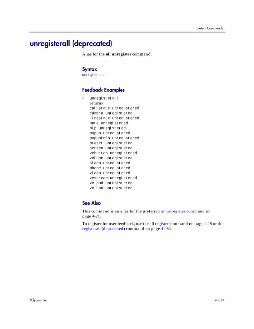
System Commands
Polycom, Inc. 4–333
unregisterall (deprecated)Alias for the all unregister command.
Syntaxunregisterall
Feedback Examples• unregisterall
returnscallstate unregisteredcamera unregisteredlinestate unregisteredmute unregisteredpip unregisteredpopup unregisteredpopupinfo unregisteredpreset unregisteredscreen unregisteredvcbutton unregisteredvolume unregisteredsleep unregisteredphone unregisteredvideo unregisteredvcstream unregisteredvc pod unregisteredvc lan unregistered
See AlsoThis command is an alias for the preferred all unregister command on page 4-21.
To register for user feedback, use the all register command on page 4-19 or the registerall (deprecated) command on page 4-284.

Integrator’s Reference Manual for Polycom HDX Systems
4–334 Polycom, Inc.
usefixedportsSets or gets the Fixed Ports configuration.
Syntaxusefixedports <get|yes|no>
Feedback Examples• usefixedports yes
returnsusefixedports yes
• usefixedports noreturnsusefixedports no
• usefixedports getreturnsusefixedports no
Parameter Description
get Returns the current setting.
yes Enables the use of Fixed Ports.
no Disables the use of Fixed Ports.
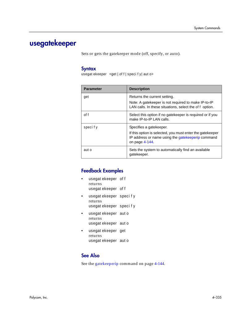
System Commands
Polycom, Inc. 4–335
usegatekeeperSets or gets the gatekeeper mode (off, specify, or auto).
Syntaxusegatekeeper <get|off|specify|auto>
Feedback Examples• usegatekeeper off
returnsusegatekeeper off
• usegatekeeper specifyreturnsusegatekeeper specify
• usegatekeeper autoreturnsusegatekeeper auto
• usegatekeeper getreturnsusegatekeeper auto
See AlsoSee the gatekeeperip command on page 4-144.
Parameter Description
get Returns the current setting.
Note: A gatekeeper is not required to make IP-to-IP LAN calls. In these situations, select the off option.
off Select this option if no gatekeeper is required or if you make IP-to-IP LAN calls.
specify Specifies a gatekeeper.
If this option is selected, you must enter the gatekeeper IP address or name using the gatekeeperip command on page 4-144.
auto Sets the system to automatically find an available gatekeeper.

Integrator’s Reference Manual for Polycom HDX Systems
4–336 Polycom, Inc.
usepathnavigatorSets or gets the Polycom PathNavigator™ mode, Polycom ReadiManager® SE200 mode, or Polycom Converged Management Application™ (CMA®) mode if the PathNavigator, ReadiManager, or Polycom CMA system is used with the Polycom HDX system.
Syntaxusepathnavigator <get|always|never|required>
Feedback Examples• usepathnavigator always
returnsusepathnavigator always
• usepathnavigator neverreturnsusepathnavigator never
• usepathnavigator requiredreturnsusepathnavigator required
• usepathnavigator getreturnsusepathnavigator required
Parameter Description
get Returns the current setting.
always Always use the Conference on Demand feature available with the PathNavigator, ReadiManager, or Polycom CMA system to place a multipoint call. Never use the Polycom HDX system’s internal multipoint capability.
never Never use the Conference on Demand feature available with the PathNavigator, ReadiManager, or Polycom CMA system to place a multipoint call. Use the Polycom HDX system’s internal multipoint capability instead.
required This is the default. When this option is selected, the multipoint call is handled by the Polycom HDX system’s internal multipoint capability if possible; otherwise, the multipoint call is handled through the Conference on Demand feature available with the PathNavigator, ReadiManager, or Polycom CMA system.

System Commands
Polycom, Inc. 4–337
CommentsThis option is only accessible if the PathNavigator, ReadiManager, or Polycom CMA system is used.
The PathNavigator uses the Polycom MGC™ and can handle video conferences with more participants and higher speeds than a Polycom HDX system’s internal multipoint capability.
The PathNavigator, ReadiManager, and Polycom CMA systems support ad-hoc multipoint video conferencing through the Conference on Demand feature, which allows users to bring multiple endpoints together in a video conference on an unscheduled basis. It allows users to place multipoint video calls to remote participants by only using their names and/or the numbers that correspond to those remote locations.

Integrator’s Reference Manual for Polycom HDX Systems
4–338 Polycom, Inc.
useroompasswordSets or gets the Use Room Password for Remote Access setting.
Syntaxuseroompassword getuseroompassword <yes|no>
Feedback Examples• useroompassword yes
returnsuseroompassword yes
• useroompassword noreturnsuseroompassword no
• useroompassword getreturnsuseroompassword no
Parameter Description
get Returns the current setting.
no Configures the system to use a separate room password and remote access password.
yes Configures the system to use the same password for room and remote access.

System Commands
Polycom, Inc. 4–339
v35broadcastmodeSets or gets the V.35 broadcast mode. This command is only applicable if you have a V.35 network interface connected to your system.
Syntaxv35broadcastmode <get|on|off>
Feedback Examples• v35broadcast on
returnsv35broadcast on
• v35broadcast offreturnsv35broadcast off
• v35broadcast getreturnsv35broadcast off
Parameter Description
get Returns the current setting.
on Turns on V.35 broadcast. This paramater is not allowed while in a call.
off Turns off V.35 broadcast. This paramater is not allowed while in a call.
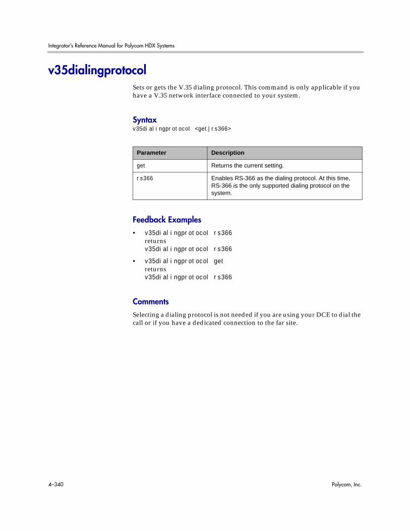
Integrator’s Reference Manual for Polycom HDX Systems
4–340 Polycom, Inc.
v35dialingprotocolSets or gets the V.35 dialing protocol. This command is only applicable if you have a V.35 network interface connected to your system.
Syntaxv35dialingprotocol <get|rs366>
Feedback Examples• v35dialingprotocol rs366
returnsv35dialingprotocol rs366
• v35dialingprotocol getreturnsv35dialingprotocol rs366
CommentsSelecting a dialing protocol is not needed if you are using your DCE to dial the call or if you have a dedicated connection to the far site.
Parameter Description
get Returns the current setting.
rs366 Enables RS-366 as the dialing protocol. At this time, RS-366 is the only supported dialing protocol on the system.

System Commands
Polycom, Inc. 4–341
v35numSets or gets the ISDN video numbers assigned to the system. This command is only applicable if you have a V.35 network interface connected to your system.
Syntaxv35num get <1b1|1b2>v35num set <1b1|1b2> ["v35 number"]
Feedback Examples• v35num set 1b1
returnsv35num 1b1 <empty>
• v35num set 1b2 7005551212returnsv35num 1b2 7005551212
• v35num get 1b2returnsv35num 1b2 7005551212
CommentsThe 1b1 and 1b2 parameters follow the convention and nomenclature of the user interface and the isdnnum command on page 4-209.
Parameter Description
get Returns the current ISDN video number associated with a B channel of a particular line. Requires <1b1|1b2>.
1b1|1b2 B1 and B2 channels:
1b1 designates line 1, B channel 1 (B1).
1b2 designates line 1, B channel 2 (B2).
set Sets the ISDN video number for a B channel line when followed by a “v35 number” parameter. To erase the current setting, omit the “v35 number” parameter. 1b1 is port 1 and 1b2 is port 2. This paramater is not allowed while in a call.
“v35 number” Numeric string. This is the ISDN video number(s) provided by your network service provider.

Integrator’s Reference Manual for Polycom HDX Systems
4–342 Polycom, Inc.
See AlsoSee the isdnnum command on page 4-209.
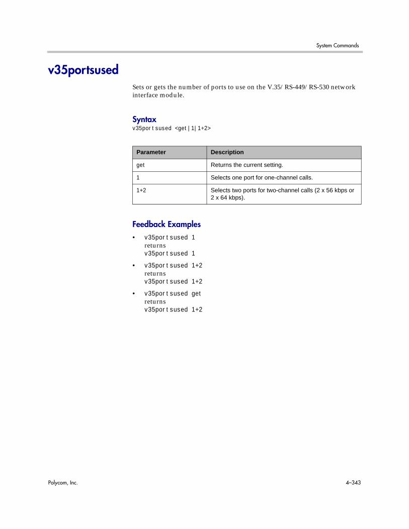
System Commands
Polycom, Inc. 4–343
v35portsusedSets or gets the number of ports to use on the V.35/RS-449/RS-530 network interface module.
Syntaxv35portsused <get|1|1+2>
Feedback Examples• v35portsused 1
returnsv35portsused 1
• v35portsused 1+2returnsv35portsused 1+2
• v35portsused getreturnsv35portsused 1+2
Parameter Description
get Returns the current setting.
1 Selects one port for one-channel calls.
1+2 Selects two ports for two-channel calls (2 x 56 kbps or 2 x 64 kbps).
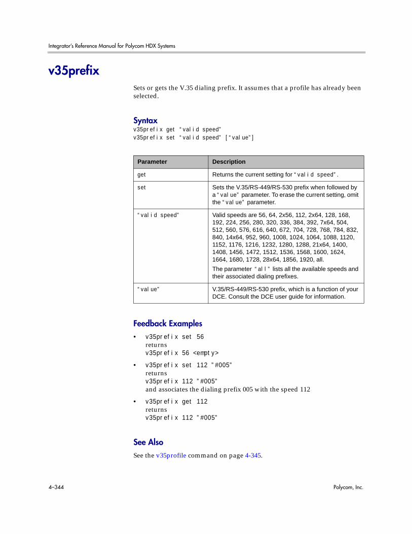
Integrator’s Reference Manual for Polycom HDX Systems
4–344 Polycom, Inc.
v35prefixSets or gets the V.35 dialing prefix. It assumes that a profile has already been selected.
Syntaxv35prefix get “valid speed”v35prefix set “valid speed” [“value”]
Feedback Examples• v35prefix set 56
returnsv35prefix 56 <empty>
• v35prefix set 112 ”#005”returnsv35prefix 112 ”#005”and associates the dialing prefix 005 with the speed 112
• v35prefix get 112returnsv35prefix 112 ”#005”
See AlsoSee the v35profile command on page 4-345.
Parameter Description
get Returns the current setting for “valid speed”.
set Sets the V.35/RS-449/RS-530 prefix when followed by a “value” parameter. To erase the current setting, omit the “value” parameter.
“valid speed” Valid speeds are 56, 64, 2x56, 112, 2x64, 128, 168, 192, 224, 256, 280, 320, 336, 384, 392, 7x64, 504, 512, 560, 576, 616, 640, 672, 704, 728, 768, 784, 832, 840, 14x64, 952, 960, 1008, 1024, 1064, 1088, 1120, 1152, 1176, 1216, 1232, 1280, 1288, 21x64, 1400, 1408, 1456, 1472, 1512, 1536, 1568, 1600, 1624, 1664, 1680, 1728, 28x64, 1856, 1920, all.
The parameter “all” lists all the available speeds and their associated dialing prefixes.
“value” V.35/RS-449/RS-530 prefix, which is a function of your DCE. Consult the DCE user guide for information.

System Commands
Polycom, Inc. 4–345
v35profileSets or gets a V.35 profile associated with dialing through a DCE. It can also display all the settings (speed, prefix or suffix) of the current profile.
Syntaxv35profile <get|adtran|adtran_isu512|ascend|ascend_vsx|ascend_max|avaya_mcu|custom_1|fvc.com|initia|lucent_mcu|madge_teleos>
Feedback Examples• v35profile adtran_isu512
returnsv35profile adtran_isu512selects adtran_isu512 as the profile
• v35profile getreturnsv35profile adtran_isu512
Parameter Description
get Returns the current profile.
adtran|adtran_isu512|ascend|ascend_vsx|ascend_max|avaya_mcu|custom_1|fvc.com|initia|lucent_mcu|madge_teleos
V.35/RS-449/RS-530 profile (equipment/manufacturer) available.
Consult your DCE user guide for additional information on setting dialing profiles.

Integrator’s Reference Manual for Polycom HDX Systems
4–346 Polycom, Inc.
v35suffixSets or gets the V.35 dialing suffix. It assumes that a profile has already been selected.
Syntaxv35suffix get “valid speed”v35suffix set “valid speed” [“value”]
Feedback Examples• v35suffix set 128
returnsv35suffix 128 <empty>
• v35suffix set 128 ”#4#2”returnsv35suffix 128 #4#2and associates the dialing suffix #4#2 with the speed 128
• v35suffix get 128returnsv35suffix 128 #4#2
See AlsoSee the v35profile command on page 4-345.
Parameter Description
get Returns the current setting for valid speed.
set Sets the dialing suffix when followed by a “value” parameter. To erase the current setting, omit the “value” parameter.
“valid speed” Valid speeds are 56, 64, 2x56, 112, 2x64, 128, 168, 192, 224, 256, 280, 320, 336, 384, 392, 7x64, 504, 512, 560, 576, 616, 640, 672, 704, 728, 768, 784, 832, 840, 14x64, 952, 960, 1008, 1024, 1064, 1088, 1120, 1152, 1176, 1216, 1232, 1280, 1288, 21x64, 1400, 1408, 1456, 1472, 1512, 1536, 1568, 1600, 1624, 1664, 1680, 1728, 28x64, 1856, 1920, all.
The parameter “all” lists all the available speeds and their associated dialing prefixes.
“value” The dialing suffix, which is a function of your DCE. Consult the DCE user guide for information.

System Commands
Polycom, Inc. 4–347
validateacctnumSets or gets the validation for the Global Management System account number that is used when dialing out.
Syntaxvalidateacctnum <get|yes|no>
Feedback Examples• validateacctnum yes
returnsvalidateacctnum yes
• validateacctnum noreturnsvalidateacctnum no
• validateacctnum getreturnsvalidateacctnum no
CommentsWhen the call connects, the system verifies that the account exists with the Global Management System server. If the account does not exist, the call is disconnected.
This option is only available if Required Account Number to Dial is enabled.
Parameter Description
get Returns the current setting.
yes Enables the Global Management System account number validation option.
no Disables the Global Management System account number validation option.

Integrator’s Reference Manual for Polycom HDX Systems
4–348 Polycom, Inc.
vcbuttonControls a content video source. It can also register or unregister the API session to receive notification of content events.
Syntaxvcbutton play {2..5}vcbutton <get|stop|register|unregister>vcbutton map <get|{2..5}>vcbutton source get
Parameter Description
play Starts sending the content from the specified content video source. If no content video source is specified, starts sending content from the default content video source. Starts content from any content video source without the need to change source mapping and without needing to stop the currently playing content video source. Fails and does not stop the current content video source if the specified content video source is not valid. Stops the current content video source if the specified content video source is valid but is currently unavailable.
{2..5} Specifies a content video source.
get Returns the current setting (play or stop).
stop Stops sending content from the content video source that is currently playing.
register Registers the API session to receive notifications about content events.
unregister Unregisters the API session to receive notifications about content events.
map get Gets the content video source currently specified for control.
map {2..5} Specifies the content video source to control. Note: This parameter is only necessary if no video source was specified when using the vcbutton play command.
source get Gets the content video source that is currently playing.
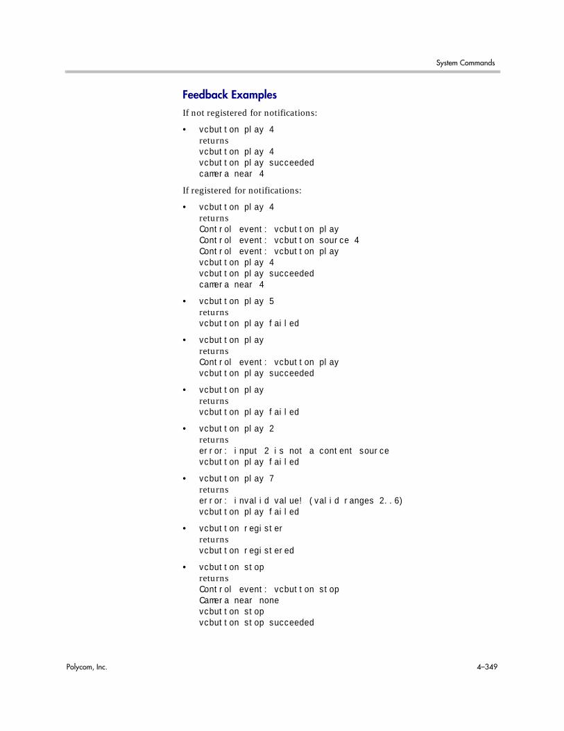
System Commands
Polycom, Inc. 4–349
Feedback ExamplesIf not registered for notifications:
• vcbutton play 4returnsvcbutton play 4vcbutton play succeededcamera near 4
If registered for notifications:
• vcbutton play 4returnsControl event: vcbutton playControl event: vcbutton source 4Control event: vcbutton playvcbutton play 4vcbutton play succeededcamera near 4
• vcbutton play 5returnsvcbutton play failed
• vcbutton playreturnsControl event: vcbutton playvcbutton play succeeded
• vcbutton playreturnsvcbutton play failed
• vcbutton play 2returnserror: input 2 is not a content sourcevcbutton play failed
• vcbutton play 7returnserror: invalid value! (valid ranges 2..6)vcbutton play failed
• vcbutton registerreturnsvcbutton registered
• vcbutton stopreturnsControl event: vcbutton stopCamera near nonevcbutton stopvcbutton stop succeeded

Integrator’s Reference Manual for Polycom HDX Systems
4–350 Polycom, Inc.
• vcbutton getreturnsvcbutton stopvcbutton get succeeded
• vcbutton source getreturnsvcbutton source get 1vcbutton source get succeeded
• vcbutton source getreturnsvcbutton source get nonevcbutton source get succeeded
Polycom recommends registering for notifications. If vcbutton register is used for notifications, the following responses occur.
• Pressing the play button at the far sitereturnsControl event: vcbutton farplay
• Pressing the stop button on the local systemreturnsControl event: vcbutton stop
CommentsThe vcbutton stop command is global in Polycom HDX software version 2.0 or later. Previously, this command was specific to the content video source to which it was mapped.

System Commands
Polycom, Inc. 4–351
vcraudiooutEnables, disables, or gets the VCR Audio Out Always On setting.
Syntaxvcraudioout <get|yes|no>
Feedback Examples• vcraudioout yes
returnsvcraudioout yes
• vcraudioout noreturnsvcraudioout no
• vcraudioout getreturnsvcraudioout no
Parameter Description
get Returns the current setting.
yes Enables VCR Audio Out Always On.
no Disables VCR Audio Out Always On.

Integrator’s Reference Manual for Polycom HDX Systems
4–352 Polycom, Inc.
vcrrecordsourceSets or gets the VCR/DVD record source.
Syntaxvcrrecordsource getvcrrecordsource <near|far|auto|content|content-or-near|content-or-far|content-or-auto|none>
Feedback Examples• vcrrecordsource near
returnsvcrrecordsource near
• vcrrecordsource content-or-autoreturnsvcrrecordsource content-or-auto
• vcrrecordsource getreturnsvcrrecordsource content-or-auto
Parameter Description
get Returns the current setting.
near Sets the VCR to record the near-site video source.
far Sets the VCR to record the far-site video source.
auto Sets the VCR to automatically record the current speaker in a point-to-point call.
content Sets the VCR to record content, when presented.
content-or-near Sets the VCR to record near-site video or content, when presented.
content-or-far Sets the VCR to record far-site video or content, when presented.
content-or-auto Sets the VCR to record the current speaker or content, when presented.
none Sets the VCR to record nothing.

System Commands
Polycom, Inc. 4–353
versionReturns the current system’s version information.
Syntaxversion
Feedback Examples• version
returnsversion “release 2.5 - 30Nov2008 11:30”

Integrator’s Reference Manual for Polycom HDX Systems
4–354 Polycom, Inc.
vgaqualitypreferenceSets or gets the bandwidth split for people and content video.
Syntaxvgaqualitypreference getvgaqualitypreference <content|people|both>
Feedback Examples• vgaqualitypreference people
returnsvgaqualitypreference people
• vgaqualitypreference contentreturnsvgaqualitypreference content
• vgaqualitypreference bothreturnsvgaqualitypreference both
• vgaqualitypreference getreturnsvgaqualitypreference both
Parameter Description
get Returns the current setting.
content Sets the VGA quality preference to content video.
people Sets the VGA quality preference to people video.
both Sets the VGA quality preference to both people and content video.

System Commands
Polycom, Inc. 4–355
videocallorderSets the video call order of the specified protocol to the specified slot.
Syntaxvideocallorder <isdn|h323|sip|gateway323> <1|2|3|4>
Feedback Examples• videocallorder h323 1
returnsvideocallorder h323 1
• videocallorder isdn 2returnsvideocallorder isdn 2
See AlsoTo set the dialing order for audio-only protocols, use the voicecallorder command on page 4-356.
Parameter Description
isdn Specifies ISDN protocol.
h323 Specifies IP protocol.
sip Specifies SIP protocol.
gateway323 Specifies H.323 gateway calling.
1|2|3|4 Sets the order in which the specified protocol is attempted when a video call is placed.

Integrator’s Reference Manual for Polycom HDX Systems
4–356 Polycom, Inc.
voicecallorderSets the voice call order of the specified protocol to the specified slot.
Syntaxvoicecallorder <isdn_phone|pots> <1|2>
Feedback Examples• voicecallorder pots 1
returnsvoicecallorder pots 1
• voicecallorder isdn_phone 1returnsvoicecallorder isdn_phone 1
See AlsoTo set the dialing order for video protocols, use the videocallorder command on page 4-355.
Parameter Description
isdn_phone Specifies ISDN phone line.
pots Specifies analog phone line.
1|2 Sets the order in which the specified method is attempted when a voice call is placed. Positions 1-2 are relative and are shown as 3-4 in the user interface if video protocols are enabled.

System Commands
Polycom, Inc. 4–357
volumeSets or gets the call audio volume (not sound effects) on the system or registration for volume changes.
Syntaxvolume <register|unregister>volume <get|up|down|set {0..50}>volume range
Feedback Examples• volume register
returnsvolume registered
• If entered again,volume registerreturnsinfo: event/notification already active:volume
• volume set 23returnsvolume 23
• volume upreturnsvolume 24
• volume getreturnsvolume 24
Parameter Description
register Registers to receive notification when the volume changes.
unregister Disables register mode.
get Returns the current volume level.
up Increases the audio volume by 1.
down Decreases the audio volume by 1.
set Sets the volume to a specified level. Requires a volume setting from {0..50}.
range Returns the valid volume range available to the user.

Integrator’s Reference Manual for Polycom HDX Systems
4–358 Polycom, Inc.
CommentsChanges the call audio volume (not sound effects) on the system.

System Commands
Polycom, Inc. 4–359
vortexSends commands to a Polycom Vortex mixer.
Syntaxvortex <0|1> mute <on|off>vortex <0|1> forward “vortex_macro”
Feedback ExamplesThe response from the Vortex is returned in the following format:vortex <portnum> forward <vortexcmd>:<vortexresponse>
• vortex 0 forward F00PINGreturnsvortex 0 forward F00PING:F00PONGif the Vortex responds andvortex 0 forward F00PING:failedif the Vortex does not respond
• vortex 1 mute onreturnsvortex 1 mute onand mutes the Vortex connected to the second serial port on the back of the system
Parameter Description
0|1 Specifies the serial port to which the Vortex mixer is connected.
mute Sets the mute state for the Vortex mixer connected to the specified serial port.
on Mutes the Vortex mixer.
off Unmutes the Vortex mixer.
forward Forwards the vortex_macro to the Vortex mixer connected to the specified serial port.
“vortex_macro” Specifies the Vortex mixer macro command to send. For more information about these commands, refer to the Vortex documentation.

Integrator’s Reference Manual for Polycom HDX Systems
4–360 Polycom, Inc.
CommentsThe Vortex commands are applicable when you have a Vortex mixer connected to a system. An API client can send these commands to control a Vortex mixer using the command format: vortex <portnum> forward <vortexcmd>where <portnum> is 0 if the Vortex is connected to the first serial port or 1 if the Vortex is connected to the second serial port, and <vortexcmd> is a Vortex-specific command. Whatever value is passed in this parameter will be sent to the Vortex.

System Commands
Polycom, Inc. 4–361
waitforThis command is used within script files or control panel programs to wait for a specific event before executing the next statement. It causes the API session to wait until a call being placed either connects or fails, or until system is ready to place a call (such as after a reboot waiting for the ISDN lines to come up).
Syntaxwaitfor <callcomplete|systemready>
Feedback Examples• waitfor callcomplete
returnswaiting for call completeand returnscall is completewhen the call either connects or fails
• waitfor systemreadyreturnswaiting for system readyand returnssystem is readywhen the system is ready to make a call
CommentsThis command can be used to synchronize a remote controller with the system. The API session echoes the message “call complete” when the call connects or is aborted.
Parameter Description
callcomplete Causes the API session to wait until a call being placed either connects or fails.
systemready Causes the system to return the message “system is ready” when the system is ready to make a call.

Integrator’s Reference Manual for Polycom HDX Systems
4–362 Polycom, Inc.
wakeWakes the system from sleep mode.
Syntaxwake
Feedback Examples• wake
returnswakeand wakes the system from sleep mode
See AlsoTo put the system in sleep mode, use the sleep command on page 4-307.

System Commands
Polycom, Inc. 4–363
wanipaddressSets or gets the WAN IP address.
Syntaxwanipaddress getwanipaddress set [“xxx.xxx.xxx.xxx”]
Feedback Examples• wanipaddress set 192.168.1.101
returnswanipaddress 192.168.1.101
• wanipaddress getreturnswanipaddress 192.168.1.101
CommentsThe NAT Configuration option on the Firewall screen must be set to Auto, Manual, or UPnP for this option to be available.
Parameter Description
set Sets the WAN IP address when followed by the “xxx.xxx.xxx.xxx” parameter. To erase the current setting, omit the “xxx.xxx.xxx.xxx” parameter.
get Returns the WAN IP address.
“xxx.xxx.xxx.xxx” WAN IP address.
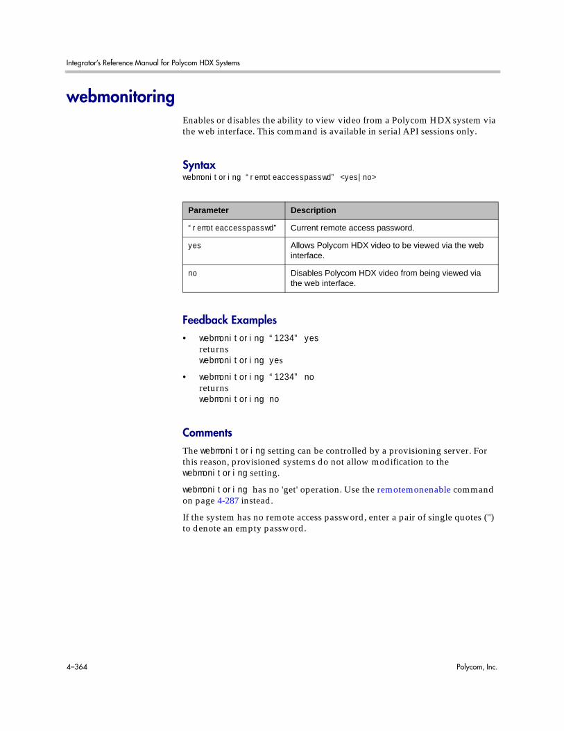
Integrator’s Reference Manual for Polycom HDX Systems
4–364 Polycom, Inc.
webmonitoringEnables or disables the ability to view video from a Polycom HDX system via the web interface. This command is available in serial API sessions only.
Syntaxwebmonitoring “remoteaccesspasswd” <yes|no>
Feedback Examples• webmonitoring “1234” yes
returnswebmonitoring yes
• webmonitoring “1234” noreturnswebmonitoring no
CommentsThe webmonitoring setting can be controlled by a provisioning server. For this reason, provisioned systems do not allow modification to the webmonitoring setting.
webmonitoring has no 'get' operation. Use the remotemonenable command on page 4-287 instead.
If the system has no remote access password, enter a pair of single quotes ('') to denote an empty password.
Parameter Description
“remoteaccesspasswd” Current remote access password.
yes Allows Polycom HDX video to be viewed via the web interface.
no Disables Polycom HDX video from being viewed via the web interface.
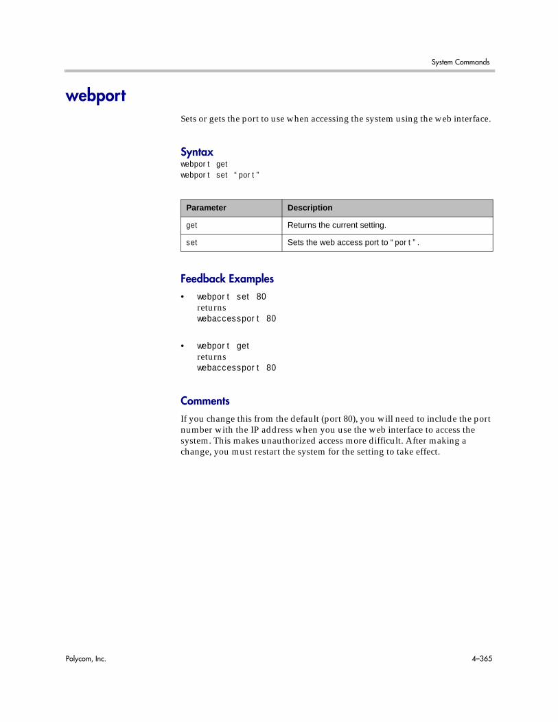
System Commands
Polycom, Inc. 4–365
webportSets or gets the port to use when accessing the system using the web interface.
Syntaxwebport getwebport set “port”
Feedback Examples• webport set 80
returnswebaccessport 80
• webport getreturnswebaccessport 80
CommentsIf you change this from the default (port 80), you will need to include the port number with the IP address when you use the web interface to access the system. This makes unauthorized access more difficult. After making a change, you must restart the system for the setting to take effect.
Parameter Description
get Returns the current setting.
set Sets the web access port to “port”.

Integrator’s Reference Manual for Polycom HDX Systems
4–366 Polycom, Inc.
whitelistenabledEnables or disables the ability to restrict a Polycom HDX system’s access to only those systems with IP addresses that match one of the addresses or patterns specified in the whitelist.
Syntaxwhitelistenabled getwhitelistenabled <yes|no>
Feedback Examples• whitelistenabled get
returnswhitelistenabled no
• whitelistenabled yesreturnswhitelistenabled yes
CommentsThe system will restart when the whitelistenabled setting is modified.
Parameter Description
get Returns the current setting.
yes Allows the Polycom HDX system to access only those systems with IP addresses that match one of the addresses or patterns specified in the whitelist.
no Allows the Polycom HDX system to access systems with IP addresses that are not specified in the whitelist.

System Commands
Polycom, Inc. 4–367
whoamiDisplays the same initial banner information as when the RS-232/Telnet session was started with the system.
Syntaxwhoami
Feedback Examples• whoami
returnsHi, my name is: Polycom HDX DemoHere is what I know about myself:Model: HDX9004Serial Number: 82065205E72EC1Software Version: 2.5Build Information: root on domain.polycom.comContact Number: <empty>Time In Last Call: 0:43:50Total Time In Calls: 87:17:17Total Calls: 819SNTP Time Service: auto insync ntp1.polycom.comLocal Time is: Wed, 30 Nov 2008 10:41:46Network Interface: NONEIP Video Number: 192.168.1.101Link-Local Address: fe80::2e0:dbff:fe07:2173/64ISDN Video Number: 7005551212MP Enabled: AB1C-2D34-5EF6-7890-GHI1H323 Enabled: TrueH320 Enabled: FalseHTTP Enabled: TrueSNMP Enabled: True
CommentsThe response can vary depending on your system configuration.

Integrator’s Reference Manual for Polycom HDX Systems
4–368 Polycom, Inc.

Polycom, Inc. A–1
ARoom Design and Layout
Reprinted from the Basics of Audio and Visual Systems Design: Revised Edition, Chapter 12, “Videoconferencing” written by Scott Sharer, CTS, and Jim Smith, CVE, CTS, copyright 2003, with permission of InfoComm International® www.infocomm.org
For clarity of discussion, we have divided this section into the following sub-sections:
• Room construction, including wall construction, windows and window treatments, ceilings and HVAC;
• Interior design and finishes;
• Furniture design, including placement and layout;
• Room acoustics and acoustic treatment; and
• Room lighting.
The initial layout and construction of the space affects all the elements that are discussed in other sections of this book [Basics of Audio and Visual Systems Design], including acoustic characteristics and performance, general and ambient light control, and overall comfort.
Room RequirementsWe begin with general room requirements. The total floor space required for VC is much greater than we have become used to for general local presentation and meeting. In architectural terms it is not uncommon to find a rule-of-thumb applied that allows for up to 15 square feet of floor space per participant in a traditional presentation or meeting room. If there is a front-of-room presenter position at a podium, and if there is some use of in-room technology (projection devices, whiteboards, etc.), then this figure may increase to as much as 20 square feet of floor space per participant, but rarely any more than that.
It is here that we have our first conflict. In videoconferencing we have to consider not only the issues related to local viewing and hearing but also the issues of being seen and heard by people at the far-end of the connection. This

Integrator’s Reference Manual for Polycom HDX Systems
A–2 Polycom, Inc.
means that we must consider sight lines and angles of participant interaction that go beyond traditional presentation environments. As a rule we should allow not less than 30 square feet and generally not more than 45 square feet of floor space per participant in a videoconference space. Though two to three times what we are used to allowing, this amount ensures that local participants will see one another and the display of local and remote electronic images. It also ensures that participants at the far-end will see and hear everyone arriving at their location via the connection, and that all will see and hear at a level of quality that does not detract and, in the best deployment, even enhances the communications.
Having determined the required size of the space, we can move on to the actual renovation or construction of the space itself. Again the requirements here are generally less forgiving than those applied in local-only meeting spaces. In the most basic sense this is because, by sheer definition, at least some of the participants in a conference-based meeting are not actually in the room. As such, we cannot count on the typical human mechanisms (the human ears and brain and our ability to locate sound in three-dimensional space) to manage any acoustic anomalies.
If we are, for example, in a room that is adjacent to a double-door entry to the building, then knowing this we can take the inevitable doorway noise into account as we filter the sounds we hear both inside the meeting room and coming from that adjacent entryway. Within our own physical and local environment we have the ability to isolate local unwanted noise from local “sound of interest” (voices of other people, etc.), and place the unwanted noise in an inferior position in our conscious thought pattern. We are able to do this because we know where the noise is coming from and (usually) what is causing it. We may be annoyed by the noise, but we generally are able to ignore it. As soon as we add conferencing to the meeting equation, however, we add the element of electronic pickup and reproduction of all sounds. For the people at the far-end, the unwanted noise is much more difficult (if not impossible) to ignore. They do not have the ability to isolate it in three-dimensional space (the microphones eliminate the spatial reference) and they often do not know what is making the noise. The brain of the far-end participant will devote more and more conscious observation and thought energy to trying to work out these elements, in an attempt to isolate and finally “ignore” the unwanted sound. We have already stated that they cannot do this, however, due to the electronic separation between the locations. Thus they are left with an impossible task that takes up more and more thought energy, eroding the perceived quality of the spoken communication over time. Frustration and exasperation quickly set in, and the communication flow quickly falls apart.
This, then, is one reason we must pay even greater attention to the acoustic and visual issues for any presentation space that will be connected via conference to another. Minor, seemingly insignificant anomalies we often ignore in the local environment become significant impediments to smooth communication with people at the far-end of any connection. In short, we must always ask ourselves, “What does this look like and sound like to the people at the farend?”

Room Design and Layout
Polycom, Inc. A–3
In order to guarantee that the final conference environment will have a solid foundation, we begin with the construction of the walls, floors and ceilings for videoconference spaces.
WallsConference room walls should be built from slab to slab. That is, there should be no gaps from the concrete of one floor to the concrete of the next floor. Resilient, gypsum board mountings should be used to close any gaps. The thickness of the gypsum board should be 5/8” or more (one layer of 5/8” and one layer of 1/2” bonded together would be ideal) on the inside of the room, with 1/2” thick (or as required by local building codes) appropriate for the outside of the walls. There should always be a difference in thickness between the materials used on the inner versus the outer walls. That difference in thickness subdues mechanical coupling (vibration) between the two layers. A good overall wall thickness is 6”. It is recommended that “offset stud” construction be used, typically a 6” header and footer with 3.5” verticals attached in an alternating pattern one toward the outside of the footer, the next toward the inside and so on.
Fiberglass dense batting or mineral rock wool, 4” to 6” thick (the equivalent of R-11 to R-13) should be placed in the wall space. The thickness of the batting is not critical. The critical aspect is that it must be loosely placed in the wall space, not compacted to fit. The resultant wall will have excellent acoustic isolation from the outside world. More significant acoustic isolation can be achieved by placing an additional barrier layer within the wall space. Typically this barrier will be made of a dense polymer material, about 1/8” thick, and the improvement regarding loss of sound transmitted through the wall will be roughly a factor of 10. These materials are available from a variety of manufacturers.
WindowsWindows usually present the equivalent of an acoustic nightmare (as well as altering the way a camera renders colors and brightness). They not only transmit room sound, but also allow unwanted outside noise to intrude on the conference space. In the event that windows cannot be avoided, it becomes essential that window treatment of some sort be used. This treatment should match the interior look and feel of the space, while providing a high level of sound and light block. Typically a heavyweight drape (24 ounces or more) of heavy fullness (not less than 6” fullness on not less than 8” centers per fold) is preferred. In all cases, the use of sheer draperies or standard vertical or horizontal blinds should be avoided, due to their inherent inefficiency in blocking sound and light, and the fine lines they create within the camera field of view.

Integrator’s Reference Manual for Polycom HDX Systems
A–4 Polycom, Inc.
Ceiling TilesThese should be high-quality acoustic tiles, ideally 1”- thick compressed densecore fiberglass. An added benefit of this kind of ceiling tile is that it works well with the indirect lighting as specified elsewhere in this section. To reduce any extraneous noise from leaving or entering the room via the ceiling space, the ceiling tiles can be blanketed completely from the plenum side, with a minimum of 6”- thick unfaced dense fiberglass batting or mineral rock wool, (the equivalent of R-15 to R-19). Here again, a barrier layer will improve the performance, but all local building codes must be followed for allowable materials in the various aspects of room acoustic modifications. To make entry and exit from the ceiling space easier, the blanket and barrier do not need to rest on the ceiling tiles, but may be suspended above it.
Air ConditioningIt is critical that all air-handling equipment (blowers, heat exchangers, solenoid valves, etc.) be located outside the physical meeting room space. This will prevent the noise burden associated with such equipment from affecting the participants of any meetings held in the room. Location of air-handling equipment within the ceiling space of a conference room often renders that room unusable for video or audio-only conferencing.
The air vents should be of open construction to eliminate “wind noise” while the system is running. These vents normally are specified as “low-velocity” diffusers. The number of air vents within the room should be sufficient to maintain a consistent temperature throughout the space. All HVAC ducts and diffusers should be oversized for the general application in the space, with minimum 2’ diameter insulated flexible ducts and matching 2’ noise dampening diffusers generally best. All ducts should be installed with gradual bends and curves rather than rigid 90-degree corners. This will minimize “thunder” sounds as the initial air pushes through the ductwork and into the room.
There should be a thermostat to control this specific room system independently of the rest of the building, and that control should be located within the room.
Important: Allow an additional 5,000 BTU of cooling capacity for a standard “roll-about” singlemonitor VC system with extended in-room peripherals (PC, document camera, scan converter, etc.) and a minimum of 10,000 BTU for a dual display multimedia presentation system with large screen displays. For the comfort of the participants, the room must accommodate these heat loads, plus the heat load of a room full of people, with minimal temperature rise.

Room Design and Layout
Polycom, Inc. A–5
Interior Design and FinishesWall colors within the field of view of the camera have a significant impact on the far-end perception of the room video quality. Certain colors are better suited to video rooms than others. The electronics and software of the videoconferencing system “builds” the images at the far-end from a gray/blue reference image. When there is a minimal difference between the room background and the reference image color, the codec has an easier time turning the image into numbers, with the result that the far-end will see a much higher quality video presentation. In general, light gray with just a touch of blue seems to work best. For rooms that have marginal lighting, slightly darker colors are quite useful.
In keeping with these color recommendations, the acoustic panels (discussed elsewhere in this section) should be ordered in light colors such as silver-gray, quartz or champagne for panels within the camera field of view. For aesthetics, however, panels may be alternated in color along the wall.
FurnitureAs we have noted, VC rooms should be slightly on the large side for the typical number of attendees. The placement of furniture should present a natural rapport with the videoconference system, but shouldn’t preclude the local interaction of conference participants. Doorways used for access to the space usually should be within the view of one of the camera presets to prevent the perception from the far-end that people could come into their meeting unseen. Doorways should not, however, be in constant, direct view of the camera system, as this may cause unwanted distractions and movement of people in the picture field.
Any tables within the conference environment should have a light top surface. Glossy tops should be avoided, as should strong colors or any bold wood grain. If glossy or saturated color surfaces are unavoidable, then proper lighting can help reduce (but not necessarily eliminate) their ill effects. The best table surface color is a flat satin finish, in neutral gray. In cases where the worst possible surfaces are present, the proper surface color effect can be achieved by using a table covering, put in place only when the room is being used for videoconferencing. This will, however, create problems related to the use of access ports in the tables or movement of end-user items across the surface.
AcousticsAdditional general elements related to the interior finish details for the space include acoustics. In terms of ambient noise level, the acoustic design goal for any conference- enabled room is at least NC-30 (NoiseCriteria-30). This level of specification dictates a very quiet space (somewhere around 40-dBCSPL

Integrator’s Reference Manual for Polycom HDX Systems
A–6 Polycom, Inc.
ambient noise level). A room built to the description found elsewhere in this section will usually fall between NC-30 and NC-35. The actual NC value is not critical; what is important is that the room be built with the intent and care required to achieve the low noise rating. Typically in architectural design, a site evaluation and analysis are required to certify the noise performance of a given space. The quieter the room, the easier it is to hear others in the same room as well as be heard by others who are participating via conference connection to a far-end location (or locations).
Almost every conference room of medium to large size (larger than 12’x15’) requires some level of acoustic treatment to provide good speech-rendering to other conference sites. The quality differences lie in the areas of intelligibility and consistency of loudness as presented to the far-end. While the people at the far-end may hear the sounds coming to them, it may be hard for them clearly to distinguish all of the vowels, consonants, inflections and nuances of actual human speech communication. (We all know that it is not simply what you say but how you say it—i.e., the inflections and intonations—that makes the difference in perceived meaning in human communications.)
Good audio practice dictates that the treated surfaces be composed of at least two nonparallel walls. And, as the VCS hardware is a potential source of distracting fan noises, the walls to be treated should include the wall immediately behind the VCS hardware, whenever this hardware is within the conference room proper. To help prevent meeting audio from leaking into adjoining hallways or offices, the walls along those areas also should be treated.
Approximately 50 percent of the wall area needs be covered with acoustic panels. The type recommended is 1” thick compressed, dense-core fiberglass, fabric-covered, or equivalent, with a SABIN (sound absorption index) value of 0.9 average. This specification is sometimes referred to as NRC (noise reduction coefficient). If reduction of sound passing through is required, then an additional barrier layer is laminated to the dense-core material, usually 3/8” thick fiber compression board. The barrier layer is placed against the existing wall material, then the acoustic absorption panels are placed on the interior-room side of that. The barrier panels will have a SABIN of 0.9, but will have an additional specification of an STC (sound transmission coefficient) of 20. STC is a measure of the amount of reduction in loudness of sound passing through the material. Having an STC rating of 20 means there is a factor of 10 reduction in the amount of sound passing through that material. A high-quality conference room wall usually has an STC of 60 or more—that is, less than 1/1,000 of the sound in the room leaks through the wall.
Room LightingThe brightness of the lighting in a videoconference room plays an important role in determining the far-end view of the meeting. When there are low to moderate amounts of light—20fc to 35fc (footcandles), typical office lighting—the distance range of “in focus” objects (depth-of-field) usually is

Room Design and Layout
Polycom, Inc. A–7
only 2’ or 3’ from nearest in-focus to furthest in-focus. With bright light (70fc or more) the range of in-focus objects can more than double. Participants at the far-end will see more people in sharp focus, and the codec will have an easier time encoding the image.
Bright standard direct fluorescent lighting has the undesirable side effect of being harsh for the local participants. In addition, the direct down lighting casts significant “drop shadows.” The result is undue stress among participants.
The best plan for videoconferencing is to use indirect lighting for 80 to 85 percent of the light, and evenly distributed direct lighting for the remaining 15 to 20 percent. The indirect light will help minimize shadows on the faces of the participants, and make the room more comfortable for viewing the far-end on the TV monitor. The direct light can be used to create backlight separation between foreground and background objects or surfaces.
There should be not less than 55fc and ideally as much as 75fc of light (770lux) on the faces of the participants in the facial field as viewed by the camera in the conference space. The light should be completely even across the field of measure or view, and of one consistent color temperature.
To best meet these requirements, indirect fluorescent lighting most often is recommended. This type of lighting works by using the upper walls and ceiling as diffuse reflectors for the light. The usual recommended color temperature for these is 3,000 to 3,800 degrees Kelvin. If there is a significant quantity of outdoor light entering the room, the lamps should be more than 5,500 degrees Kelvin.
Light FixturesThe light fixtures generally recommended for indirect lighting are available from a number of manufacturers. They typically are three-tube, 8” oval indirect up-lights, though they may take the form of chandelier-style pendant lights, wall sconces, cove lights or flushmounted specialized troughs. Many manufacturers work closely with contractors and lighting designers to ensure that the correct light levels and shadow-free zones are designed into the room, especially when used for videoconferencing. Lamps for these fixtures are available in a variety of specified color temperatures from numerous manufacturers, including Sylvania, General Electric and Osram/Phillips. Indirect fixtures are available in a number of different designs or “looks,” and can be purchased in configurations that will complement and not detract from the interior design of the space.
Lighting layout recommendations and determination of the number of fixtures needed are handled either by the architectural design firm or by submitting a complete floor plan, including reflected ceiling, walls and furniture placement, to fixture vendors. The vendors will analyze the plans and return a finished lighting layout to the customer, detailing the number of fixtures, placement and required wiring.

Integrator’s Reference Manual for Polycom HDX Systems
A–8 Polycom, Inc.
It is important to remember that the use of traditional meeting room downcans—even those that have color-corrected light sources—for any lighting in the field of view that may include human faces is to be avoided at all costs. These will result in extremely uneven fields of light, or pools, and heavy, unnatural shadows on the faces of the participants.
Room Preparation ConclusionWhen we follow the above guidelines we dramatically improve the odds for success in the final deployment of live bi-directional conference-based human communications. An added benefit is that this approach dramatically enhances the effectiveness of the room as it operates for more traditional meetings and presentations. The environment is more comfortable and flexible, and less dependent on specialized electronics for “fixing” deficiencies in the environment.
Audio ElementsOnce the space is prepared, we can focus on integration of the various audiovisual tools within the environment: audio, video and control.
Audio InputThe primary input device for the audio portion of any conference system is the microphone. Elsewhere in this book [Basics of Audio and Visual Systems Design] we have discussed how these devices operate within a given acoustic environment. We turn now to a short discussion of how these elements operate within a conference environment, where such factors as “three-to-one” rules and “critical distance” often are pushed to the limit or violated entirely.
When sound travels in a room, it follows “the inverse square law.” This means that the sound level heard at a microphone drops by a factor of four every time the distance doubles. Another important consideration in room audio design is the concept of “critical distance,” or the distance at which the loudness of the room background noise plus reverberation is less than one tenth of the loudness of voices getting to a particular microphone. (This definition is the result of research conducted by Don and Carolyn Davis. that is referenced in the chapter “Designing for Intelligibility” in the Handbook for Sound Engineers.1)
1. Davis, Don and Carolyn. “Designing for Intelligibility” in Handbook for Sound Engineers: The New Audio Cyclopedia, ed. Glen Ballou (Indianapolis: Howard Sams & Co., 1991), 1279-1297.

Room Design and Layout
Polycom, Inc. A–9
As an example, we will work with a room having an ambient noise level of approximately 60dBA-SPL. A person speaking in a normal voice is 72dBA-SPL at about 2’ distance. At 4’ the loudness drops to approximately 66dBA-SPL. This already is farther than the critical distance criteria allow, given the ambient noise level. At 8’ distance, a normal speaking voice is approximately 60dBA-SPL. Now the voice energy and the room background noise are about equal. For “send” audio systems in a room to work correctly, therefore, the room noise level would have to be below 40-45dBA-SPL at the microphones at all times. This gives us some measure by which we can begin to plan the microphone array within a space, including selection based on pickup pattern, sensitivity, noise rejection and signal-to-noise in relation to the ambient noise floor or level within the space. The good news is that a room designed and built as described in this section will provide an acoustic space where almost any properly configured and installed audio system can operate with very good results.
Perhaps the most difficult issue for any room designer or system planner is actual microphone placement within the space. Given the fact that many people view conference table space as sacred (to be used for papers, laptops, coffee cups and other end-user items), there often is a great deal of pressure to place the local microphones on the ceiling instead of on the table surface. But this approach must be taken with great caution. We have already seen the dramatic impact of changes in the distance between people (their mouths) and the microphone. Ceiling systems generally place microphones farther away from the participants’ mouths, not closer; critical distance calculations may eliminate ceiling placement from consideration for this reason alone. In addition, the ceiling surface generally is one of the noisiest areas of the room. Proximity to HVAC ducts and vents, attachment of tiles and runners to building members that are prone to vibration and shaking, and proximity to noise from other spaces migrating through the plenum make this area one of the least desirable for placement of microphones. This doesn’t, however, keep people from looking at this broad open surface as the best place for microphones, to “get them off the table.”
If ceiling placement is chosen, the system planner must select the components with great care from a manufacturer that specializes in this type of audio voice reinforcement. The manufacturer must be skilled in live audio and capable of installing the components (that is, being both able and willing to locate microphones at precisely measured distances from speakers, and locating those speakers at precisely measured intervals from each other and from the walls) to extremely tight tolerances. The system provider must fully inform the endusers of the potential downside effects of this approach. In any event, simply mounting a standard tabletop microphone on the ceiling tiles or implementing this solution in an ambient noise environment of 45dBA-SPL or greater will all but guarantee costly failure. No amount of post-microphone processing will fix the problems.

Integrator’s Reference Manual for Polycom HDX Systems
A–10 Polycom, Inc.
Audio OutputFor conference communication we do not really care about producing the thundering roar of jet aircraft engines, or other sounds reproduced on TV or in the movies. We are interested in reproducing the human voice. The tone, intonation, pitch and level of people speaking from the far-end should sound as much as possible like the sound they would make if they were speaking in the room. Given what has been covered in other sections of this book [Basics of Audio and Visual Systems Design], we will touch base here on a couple of simple, basic elements of the speaker technology we deploy in the conference room. These basics fall into three subcategories: direction, power and range/frequency response.
DirectionAs human beings, we feel most comfortable when the voice we hear appears to come from the same direction as the image of the person speaking. This means that reliance on ceiling speakers alone is not an ideal practice when the system is used for videoconferencing. In many small and medium-sized systems, front-firing speakers alone can provide proper direction and adequate coverage. Larger rooms (greater than 12’x15’) probably need both front-firing and side or top-fill speakers in order to maintain proper coverage at nominal power levels.
In planning systems for larger rooms, we need to take advantage of the HAAS effect. Basically stated, this is the human brain’s interpretation of sound direction when the same sound arrives at the ear from two or more directions within a certain time period. We attribute the direction of the sound to the direction from which the sound is first perceived, even if it is mixed with that same sound arriving from a completely different direction, as long as the two (or more) instances of the sound are within about 30ms of one another. Since sound travels faster electronically than it travels through the open air we may need to add audio delay to the side firing or ceiling speaker arrays in order to keep the primary perceived point source as the front of room/front-firing speakers.
PowerPower is a function of loudspeaker efficiency and total available system power. Most speakers operate in a power range that is broader than the range in which they operate without distortion. For the purpose of conference communication, we are interested in sound that has little or no distortion. Sound that is reproduced accurately (with no distortion) will most accurately represent the voice of the people from the far-end (our primary goal). Accurate reproduction also will aid the echo-cancellation circuitry in the system, minimizing the amount of echo that the system sends back to the people at the far-end, and thereby increasing perceived ease of intelligibility and understanding. Remember that any distortions present in the playback audio system—whether harmonic, amplitude (gain compression) or temporal (time

Room Design and Layout
Polycom, Inc. A–11
delays)—will be recognized by the echo canceller as “new audio information,” and it will send those distortions to the far-end, perhaps wreaking havoc on the system audio quality. In short, speaker power should be matched to overall audio subsystem power. The speakers should provide adequate coverage and be able to present approximately 80 to 85dBA-SPL (continuous) at the local site with the system operating at nominal power utilization, and have a peak reserve of 15 to 20dB before distortion.
Range/Frequency ResponseThe human ear is able to hear sounds in a very wide range of frequencies (as low as 70Hz and as high as 12,000Hz). The human voice is able to produce sounds in a narrower range (100Hz to 8,000Hz). Most spoken communication occurs, however, in a range that is only 150Hz to about 6,000Hz. This means that we need to select speakers that operate with ideal performance in a fairly narrow range for human voice (as opposed to speakers used for music, that may have ranges of 20Hz to 20,000Hz). We must also be alert to the crossover characteristics of the speakers we select. Many coaxial and paraxial speakers have their crossover within the middle audio frequencies, thereby inducing potential distortion within the spoken frequency range and creating anomalies within the system that hinder voice communication.
Video ElementsAs a general rule, any display used in a videoconferencing environment should be sized for the number of attendees, the physical distances involved and the type of material presented onscreen. The screen size should allow for clear and easy viewing at the various distances experienced within the room. A measure of required screen size that often is applied to projection technology is: no closer than 1.5 times the diagonal measure and no farther than 7 times that measure. Nobody should have to sit closer than 2 times the screen diagonal measure, nor farther than 8 times that measure.
Direct viewed tube-type displays (monitors) almost always are sharpest and brightest in a videoconferencing environment. “Retro-projector cabinet” displays (which look like largescreen TVs) are next in sharpness and brightness, and “front-screen” projectors come in last. Glare and uncontrolled ambient room lighting adversely affect the quality of the image most with front-screen projectors and least with direct view tubes. A very limited number of frontscreen projection systems have sufficient brightness and contrast to be useful in a properly lit videoconference room.

Integrator’s Reference Manual for Polycom HDX Systems
A–12 Polycom, Inc.
Video Projection for Use in VideoconferenceMany installations make use of video projection devices. The most important thing to remember in the planning of video projection for a videoconference space is that front projection is vastly inferior to rear projection. Front projection systems are less expensive and easier to implement, but the conflicting interest between the camera and the projection display makes this form of display a very poor choice. Front projection setups operate best when the lighting in the room is dimmed or doused. When this is done, the videoconference cameras can no longer operate, since they require even, bright, color-corrected light. A direct conflict between these two technologies is clear. In the event that a rear projection room cannot be set aside, retro-projection units can be purchased from a number of manufacturers. These units normally are available in sizes ranging from 40” to 72” diagonal measure. To display high-quality video while maintaining optimum lighting for interactive video meetings will require a projector of the “light-valve” or DLP™ class.
Regardless of the exact type of projector selected and the exact nature of “front versus rear,” there are certain essential rules for projector placement. The goal in projection is to get the image beam to aim directly into the audience’s eyes. In Western cultures the average distance from the floor to a seated person’s eye is 4’. That distance becomes the target for the direct beam of the projector. Again keep in mind that front projection should be avoided except in the most extreme cases. If it is employed at all it must be used with an extremely bright projector (2,500 lumens or greater for any space smaller than 25’x40’).
CamerasThere usually is a “main” or “local people” camera positioned on top center of the display, so that it can “see” the participants and anything necessary at the sides of the room, using pan and tilt features. If individual presentations may be made from the side or “front of audience” area of the room, an additional camera should be located at the back of the room, also mounted to allow a view of the presenters when necessary. Some cameras contain an active camera pointing system that also can be used effectively, given proper care in the mounting of the camera assembly. The area immediately surrounding the camera assembly needs to be acoustically “dead” to ensure that the voice tracking and pointing algorithms work correctly. This is another reason to pay close attention to the acoustic environment and acoustic treatment of any space intended for use with this type of camera system.
If local presentation is blended with VC for any events, we must consider the needs of the presenter who will not be “facing” the local image or inbound image displays used by the main body of the local audience. One or two monitors (and a camera) should be mounted at the back of the “audience-end” of the room, with the horizontal centerline at approximately 5’ from the floor for ease of presentation interaction between the presenter and the group(s) at the farend(s). Remember that, with the exception of PC-based information that is not in a standard composite narrowband video format, any information we

Room Design and Layout
Polycom, Inc. A–13
wish to “show” or “view” must be translated to video, most often with some sort of camera mechanism. Document cameras, 35mm slide-to-video units, video scanners and scan conversion devices all are designed to take one format of source material and convert it to a standard video signal that can be digitized, shipped to the far-end(s), and converted back to composite video for display. Which devices are selected and how they are used depends entirely on the needs and goals of the end-users of the system(s) and the format of their source materials.
Room Control ElementsTo give all participants the easiest use of the room for any and all presentation or conference purposes, a fully integrated room controller is recommended. It is important that one controller operate all devices in the room so that only one user interface needs to be learned by those managing the facility. The common controller also makes it much easier to expand and enhance room capabilities over time by adding or upgrading equipment. A proper room controller can operate and coordinate the use of lighting, curtains, displays, audio devices, VCRs and slide projectors, as well as all the conferencing equipment, including any network-related control needed. In lieu of a complete control system, a limited functionality controller can be located at the presentation interface panel to control the switching and routing of the computer graphics and configure the overhead camera video paths.
It is strongly advised that at least 20 percent of the time spent developing a videoconferencing room be devoted to this important sub-system, as it will complete the integration of the conference and presentation environment.
And remember that simpler is always better. People do not pay for technology. They pay for the benefits that technology can bring. The doorway to those benefits is a simple, straightforward and intuitive user control.

Integrator’s Reference Manual for Polycom HDX Systems
A–14 Polycom, Inc.

Polycom, Inc. B–1
BStatus Messages
Status DisplayThe call status can be displayed in a number of ways. The getcallstate command on page 4-158 returns a table listing the status, speed, and dialed number of current calls.
To display real-time status on individual B channels (incoming or outgoing calls), either register the API session with the callstate command on page 4-62, or start an outbound call with the dial command on page 4-95. These two commands will cause the system to re-direct the B channel status messages to the session which has issued one of these two commands. For example, if the RS-232 device issues a dial command, then call status is directed to the RS-232 port; if a later session on a Telnet port issues a dial command, then call status is also directed to that Telnet port.
B Channel Status Message ExampleThe following output example is for B channel status messages, where:
cs Indicates call status for one B channel.
RINGING Indicates a ring-in or ring-out and is equivalent to a 25% blue sphere on the graphical user interface.
CONNECTED Is equivalent to a 50% yellow sphere.
BONDING Indicates the bonding protocol is operational on the channel and is equivalent to a 75% orange sphere.
COMPLETE Is equivalent to a 100% green sphere.
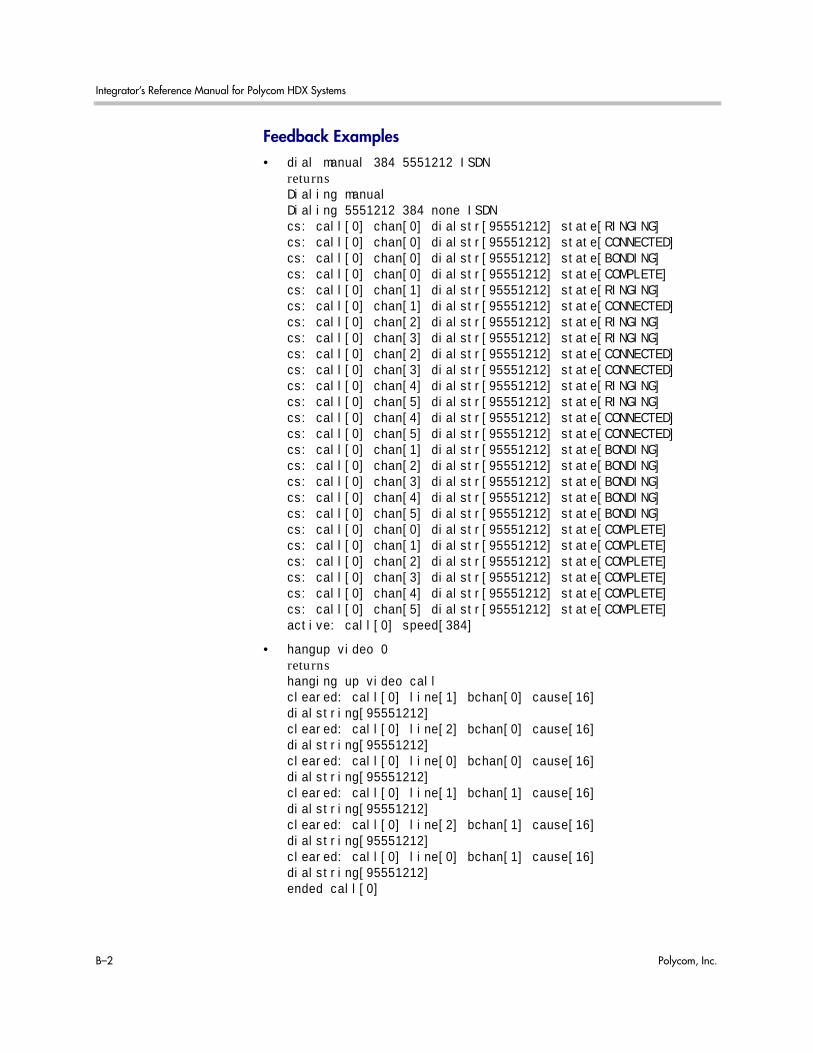
Integrator’s Reference Manual for Polycom HDX Systems
B–2 Polycom, Inc.
Feedback Examples• dial manual 384 5551212 ISDN
returnsDialing manualDialing 5551212 384 none ISDNcs: call[0] chan[0] dialstr[95551212] state[RINGING]cs: call[0] chan[0] dialstr[95551212] state[CONNECTED]cs: call[0] chan[0] dialstr[95551212] state[BONDING]cs: call[0] chan[0] dialstr[95551212] state[COMPLETE]cs: call[0] chan[1] dialstr[95551212] state[RINGING]cs: call[0] chan[1] dialstr[95551212] state[CONNECTED]cs: call[0] chan[2] dialstr[95551212] state[RINGING]cs: call[0] chan[3] dialstr[95551212] state[RINGING]cs: call[0] chan[2] dialstr[95551212] state[CONNECTED]cs: call[0] chan[3] dialstr[95551212] state[CONNECTED]cs: call[0] chan[4] dialstr[95551212] state[RINGING]cs: call[0] chan[5] dialstr[95551212] state[RINGING]cs: call[0] chan[4] dialstr[95551212] state[CONNECTED]cs: call[0] chan[5] dialstr[95551212] state[CONNECTED]cs: call[0] chan[1] dialstr[95551212] state[BONDING]cs: call[0] chan[2] dialstr[95551212] state[BONDING]cs: call[0] chan[3] dialstr[95551212] state[BONDING]cs: call[0] chan[4] dialstr[95551212] state[BONDING]cs: call[0] chan[5] dialstr[95551212] state[BONDING]cs: call[0] chan[0] dialstr[95551212] state[COMPLETE]cs: call[0] chan[1] dialstr[95551212] state[COMPLETE]cs: call[0] chan[2] dialstr[95551212] state[COMPLETE]cs: call[0] chan[3] dialstr[95551212] state[COMPLETE]cs: call[0] chan[4] dialstr[95551212] state[COMPLETE]cs: call[0] chan[5] dialstr[95551212] state[COMPLETE]active: call[0] speed[384]
• hangup video 0returnshanging up video callcleared: call[0] line[1] bchan[0] cause[16] dialstring[95551212]cleared: call[0] line[2] bchan[0] cause[16] dialstring[95551212]cleared: call[0] line[0] bchan[0] cause[16] dialstring[95551212]cleared: call[0] line[1] bchan[1] cause[16] dialstring[95551212]cleared: call[0] line[2] bchan[1] cause[16] dialstring[95551212]cleared: call[0] line[0] bchan[1] cause[16] dialstring[95551212]ended call[0]

Status Messages
Polycom, Inc. B–3
• listen videoreturnslisten video registered
listen video ringing // there is an incoming call, auto answer is oncs: call[0] chan[0] dialstr[7005551212] state[RINGING]cs: call[0] chan[0] dialstr[7005551212] state[CONNECTED]cs: call[0] chan[0] dialstr[7005551212] state[BONDING]cs: call[0] chan[0] dialstr[7005551212] state[COMPLETE]cs: call[0] chan[1] dialstr[7005551212] state[RINGING]cs: call[0] chan[1] dialstr[7005551212] state[CONNECTED]cs: call[0] chan[2] dialstr[7005551212] state[RINGING]cs: call[0] chan[3] dialstr[7005551212] state[RINGING]cs: call[0] chan[2] dialstr[7005551212] state[CONNECTED]cs: call[0] chan[3] dialstr[7005551212] state[CONNECTED]cs: call[0] chan[6] dialstr[7005551212] state[RINGING]cs: call[0] chan[6] dialstr[7005551212] state[CONNECTED]cs: call[0] chan[4] dialstr[7005551212] state[RINGING]cs: call[0] chan[5] dialstr[7005551212] state[RINGING]cs: call[0] chan[4] dialstr[7005551212] state[CONNECTED]cs: call[0] chan[5] dialstr[7005551212] state[CONNECTED]cs: call[0] chan[7] dialstr[7005551212] state[RINGING]cs: call[0] chan[7] dialstr[7005551212] state[CONNECTED]cs: call[0] chan[1] dialstr[7005551212] state[BONDING]cs: call[0] chan[2] dialstr[7005551212] state[BONDING]cs: call[0] chan[3] dialstr[7005551212] state[BONDING]cs: call[0] chan[6] dialstr[7005551212] state[BONDING]cs: call[0] chan[4] dialstr[7005551212] state[BONDING]cs: call[0] chan[5] dialstr[7005551212] state[BONDING]cs: call[0] chan[7] dialstr[7005551212] state[BONDING]cs: call[0] chan[0] dialstr[7005551212] state[COMPLETE]cs: call[0] chan[1] dialstr[7005551212] state[COMPLETE]cs: call[0] chan[2] dialstr[7005551212] state[COMPLETE]cs: call[0] chan[3] dialstr[7005551212] state[COMPLETE]cs: call[0] chan[6] dialstr[7005551212] state[COMPLETE]cs: call[0] chan[4] dialstr[7005551212] state[COMPLETE]cs: call[0] chan[5] dialstr[7005551212] state[COMPLETE]cs: call[0] chan[7] dialstr[7005551212] state[COMPLETE]active: call[0] speed[512]

Integrator’s Reference Manual for Polycom HDX Systems
B–4 Polycom, Inc.

Polycom, Inc. C–1
CPolycom HDX 9000 Series Specifications
Back Panel InformationRefer to the Administrator’s Guide for Polycom HDX Systems at www.polycom.com/videodocumentation for back panel views of Polycom HDX systems and for details about the various connections available on each Polycom HDX back panel connector.
Inputs/Outputs
Audio Specifications
Characteristic Value
Maximum Input Level
0 dBFS for Audio Input 4 +12 dBV (4.0 VRMS), ±1 dB
Maximum Input Level
0 dBFS for Audio Input 3 (VCR/DVD) +12 dBV (4.0 VRMS), ±1 dB
Maximum Input Level
0 dBFS for Audio Input 1 (External Input, Line Level)
+12 dBV (4.0 VRMS), ±1 dB
Maximum Input Level
0 dBFS for Audio Input 1 (External Input, MIC Level)
Not supported on Polycom HDX 9006 systems.
-20 dBV, ±1 dB
Input Impedance
Audio Input 4 Differential 20 k, ±5% Ohms

Integrator’s Reference Manual for Polycom HDX Systems
C–2 Polycom, Inc.
DTMF DialingThe Polycom HDX 9000 series systems generate the following tip/ring signal levels:
• Low-frequency tone: -10.2 dBV, -8.0 dBm when AC termination of the line is 600 Ohms
• High-frequency tone: -8.2 dBV, -6.0 dBm when AC termination of the line is 600 Ohms
Input Impedance
Audio Input 3 (VCR/DVD) Differential 20 k, ±5% Ohms
Input Common-Mode Rejection Ratio
Balanced Inputs, Common-Mode Amplitude 1 dBFS >60 dB, 20 Hz to 22 kHz
Maximum Output Level
Balanced Outputs (10 k Load) +12 dBV (4.0 VRMS), ±1 dB
Output Impedance
Balanced Outputs 150, ±5% Ohms
Signal-to-Noise Ratio >90 dB, A-weighted
Dynamic Range >90 dB
Crosstalk and Feed-Through 90 dB, 20 Hz to 22 kHz
Frequency Response
Balanced Inputs, Relative to 997 Hz +0.5, -3 dB, 20 Hz to 50 Hz±1 dB, 50 Hz to 20 kHz+0.5, -3 dB, 20 kHz to 22 kHz
Total Harmonic Distortion + Noise vs. Frequency
-1 dBFS Input Level
-20 dBFS Input Level
-80 dB, 20 Hz to 22 kHz
-70 dB, 20 Hz to 22 kHz
Phantom Power
DC Voltage Level, Relative to Shield Termination
DC Operating Current
Fault Current
Source Impedance
Phantom Power is not supported on Polycom HDX 9006 systems.
+48 VDC ±4 V
10 mA
16 mA
6.8 k, ±1%
Characteristic Value

Polycom HDX 9000 Series Specifications
Polycom, Inc. C–3
• The system seizes the line and waits 1.5 seconds. The number is then dialed with a 80 ms tone period followed by a 80 ms silence period for each digit.
Remote ControlThis section provides information about the IR signals for Polycom HDX systems.
Notes
• Wake up – 2.6 ms on; 2.6 ms off
• 0–559 µs (22 pulses at 38 KHz) on; 845 µs (33 pulses at 38 KHz) off
• 1–845 µs (33 pulses at 38 KHz) on; 1192 µs (46 pulses at 38 KHz) off
• EOM–559 µs (22 pulses at 38 KHz) on
• System Code consists of a User ID field (upper nibble) and the Polycom Vender Code (lower nibble) with value 0x5. The default User ID value is 0x3, so the default System Code value is 00110101 or 0x35.
• Parity is a 2-bit field consisting of a parity bit (b1) and a toggle bit (b0). Parity is even.
• Inter-burst timing is 2200 pulse times at 38.062 KHz or 57.8 ms
• 38.062 KHz signal is at 1/3 duty cycle to LED
• Multi-bit fields are transmitted most significant bit first
• Bits are labeled b0..bn, where b0 is the least significant bit
Protocol is: <Wake up> + <System Code> + <Key Code> + <Parity> + <EOM>
This information is provided for reference only. Polycom claims no responsibility or liability for programmed third-party remote control devices.
Key Name Key Code Key Code Parity
# 1100 0CH Even
* 1011 0BH Odd
0 110000 30H Even
1 110001 31H Odd
2 110010 32H Odd

Integrator’s Reference Manual for Polycom HDX Systems
C–4 Polycom, Inc.
3 110011 33H Even
4 110100 34H Odd
5 110101 35H Even
6 110110 36H Even
7 110111 37H Odd
8 111000 38H Odd
9 111001 39H Even
Auto 11001 19H Odd
Call 100101 25H Odd
Call/Hang Up 11 03H Even
Camera 11110 1EH Even
Colon 101111 2FH Odd
Delete 100010 22H Even
Dial String 0 00H Even
Directory 11010 1AH Odd
Dot 100001 21H Even
Down Arrow 110 06H Even
Far 10001 11H Even
Fast Forward 101011 2BH Even
Feet Down 10110 16H Odd
Feet Up 11000 18H Even
Hang Up 100110 26H Odd
Home 11011 1BH Even
Info (Help) 10100 14H Even
Keyboard 100011 23H Odd
Left Arrow 1001 09H Even
Low Battery 10111 17H Even
Menu (Back) 10011 13H Odd
Mute 111010 3AH Even
Near 1111 0FH Even
Key Name Key Code Key Code Parity
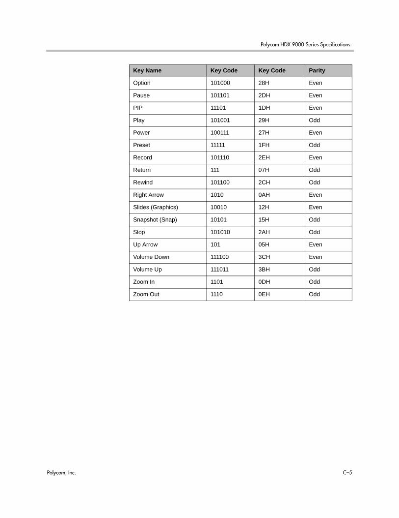
Polycom HDX 9000 Series Specifications
Polycom, Inc. C–5
Option 101000 28H Even
Pause 101101 2DH Even
PIP 11101 1DH Even
Play 101001 29H Odd
Power 100111 27H Even
Preset 11111 1FH Odd
Record 101110 2EH Even
Return 111 07H Odd
Rewind 101100 2CH Odd
Right Arrow 1010 0AH Even
Slides (Graphics) 10010 12H Even
Snapshot (Snap) 10101 15H Odd
Stop 101010 2AH Odd
Up Arrow 101 05H Even
Volume Down 111100 3CH Even
Volume Up 111011 3BH Odd
Zoom In 1101 0DH Odd
Zoom Out 1110 0EH Odd
Key Name Key Code Key Code Parity
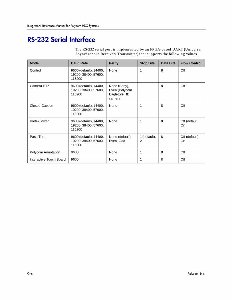
Integrator’s Reference Manual for Polycom HDX Systems
C–6 Polycom, Inc.
RS-232 Serial InterfaceThe RS-232 serial port is implemented by an FPGA-based UART (Universal Asynchronous Receiver/Transmitter) that supports the following values.
Mode Baud Rate Parity Stop Bits Data Bits Flow Control
Control 9600 (default), 14400, 19200, 38400, 57600, 115200
None 1 8 Off
Camera PTZ 9600 (default), 14400, 19200, 38400, 57600, 115200
None (Sony),Even (Polycom EagleEye HD camera)
1 8 Off
Closed Caption 9600 (default), 14400, 19200, 38400, 57600, 115200
None 1 8 Off
Vortex Mixer 9600 (default), 14400, 19200, 38400, 57600, 115200
None 1 8 Off (default), On
Pass Thru 9600 (default), 14400, 19200, 38400, 57600, 115200
None (default), Even, Odd
1 (default), 2
8 Off (default), On
Polycom Annotation 9600 None 1 8 Off
Interactive Touch Board 9600 None 1 8 Off

Polycom, Inc. D–1
DSecure RS-232 Interface API Permissions
You must log in with a password in order to start an RS-232 session if the system is configured with the Maximum Security Profile.
API Permissions TableYou can log in with either the Admin ID and Admin Remote Password or the User ID and User Remote Password of the Polycom HDX system. The available API commands depend on which type of ID you use to start the session, as shown in the following table.
API Command Parameter User ID Admin ID
! “string” 3 3
1...64 3 3
addrbook all 3 3
batch {0..59} 3 3
batch search “pattern” “count” 3 3
batch define “start_no” “stop_no” 3 3
letter {a..z} 3 3
range “start_no” “stop_no” 3 3
refresh 3 3
advnetstats 0 ...n 3 3
alertusertone get 3 3
1|2|3|4 3

Integrator’s Reference Manual for Polycom HDX Systems
D–2 Polycom, Inc.
alertvideotone get 3 3
1|2|3|4|5|6|7|8|9|1|0 3
allregister 3
allunregister 3
allowabkchanges get 3 3
yes 3
no 3
allowcamerapresetssetup get 3 3
yes 3
no 3
allowdialing get 3 3
yes 3
no 3
allowmixedcalls get 3 3
yes 3
no 3
allowusersetup get 3 3
yes 3
no 3
amxdd get 3 3
on 3
off 3
answer video 3 3
phone 3 3
areacode get 3 3
set “areacode” 3
audiometer <micleft | micright | lineinleft | lineinright | lineoutleft | lineoutright | contentinleft | contentinright | vcrinleft | vcrinright | vcroutleft | vcroutright | farendleft | farendright | off>
3 3
API Command Parameter User ID Admin ID

Secure RS-232 Interface API Permissions
Polycom, Inc. D–3
audiotransmitlevel get 3 3
up 3 3
down 3 3
register 3 3
unregister 3 3
set 3 3
autoanswer get 3 3
yes 3
no 3
donotdisturb 3
autoshowcontent get 3 3
3
3
backlightcompensation get 3 3
yes 3 3
no 3 3
basicmode get 3 3
on 3
off 3
bri1enable
bri2enable
bri3enable
bri4enable
get 3 3
yes 3
no 3
briallenable get 3 3
yes 3
no 3
API Command Parameter User ID Admin ID

Integrator’s Reference Manual for Polycom HDX Systems
D–4 Polycom, Inc.
button <# | * | 0 | 1 | 2 | 3 | 4 | 5 | 6 | 7 | 8 | 9 | .> 3 3
<down | left | right | select | up> 3 3
<auto | back | call | far | graphics | hangup | near> 3 3
<help | mute | volume+ | volume- | lowbattery | zoom+ | zoom->
3 3
<pickedup | putdown> 3 3
<camera | delete | directory | home | keyboard | period | pip | preset>
3 3
<info | menu | slides | option> 3 3
“valid_button” [“valid_button” ...] 3 3
<mmstop | mmplay | mmpause | mmrecord | mmforward | mmrewind>
3 3
calldetailreport get 3
yes 3
no 3
callinfo all 3 3
callid 3 3
callstate get 3 3
register 3 3
unregister 3 3
callstats 3 3
API Command Parameter User ID Admin ID

Secure RS-232 Interface API Permissions
Polycom, Inc. D–5
camera near {1..6} 3 3
far {1..5} 3 3
<near|far> move <left|right|up|down|zoom+|zoom-|stop>
3 3
<near|far> move <continuous|discrete> 3 3
<near|far> source 3 3
<near|far> stop 3 3
near <getposition|setposition “x” “y” “z”> 3 3
near ppcip 3 3
for-people {2..5} 3 3
for-content {2..5} 3 3
list-content 3 3
<register|unregister> 3 3
register get 3 3
tracking statistics 3 3
tracking <get|on|off> 3 3
cameradirection get 3 3
normal 3 3
reversed 3 3
camerainput <1..5> get 3 3
<1|2|3> <s-video|composite|component> 3 3
<4|5> <dvi|vga> 3 3
API Command Parameter User ID Admin ID
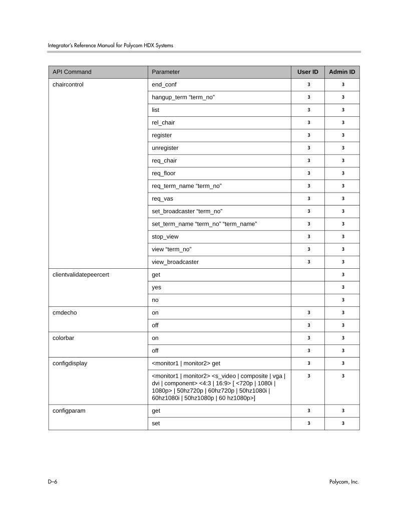
Integrator’s Reference Manual for Polycom HDX Systems
D–6 Polycom, Inc.
chaircontrol end_conf 3 3
hangup_term “term_no” 3 3
list 3 3
rel_chair 3 3
register 3 3
unregister 3 3
req_chair 3 3
req_floor 3 3
req_term_name “term_no” 3 3
req_vas 3 3
set_broadcaster “term_no” 3 3
set_term_name “term_no” “term_name” 3 3
stop_view 3 3
view “term_no” 3 3
view_broadcaster 3 3
clientvalidatepeercert get 3
yes 3
no 3
cmdecho on 3 3
off 3 3
colorbar on 3 3
off 3 3
configdisplay <monitor1 | monitor2> get 3 3
<monitor1 | monitor2> <s_video | composite | vga | dvi | component> <4:3 | 16:9> [ <720p | 1080i | 1080p> | 50hz720p | 60hz720p | 50hz1080i | 60hz1080i | 50hz1080p | 60 hz1080p>]
3 3
configparam get 3 3
set 3 3
API Command Parameter User ID Admin ID

Secure RS-232 Interface API Permissions
Polycom, Inc. D–7
configpresentation get 3 3
<monitor1 | monitor2> get 3 3
<monitor1 | monitor2> <near | far | content | near-or-far | content-or-near | content-or-far | all | none>
3 3
monitor1 "value" monitor2 "value" 3 3
confirmdiradd get 3 3
yes 3
no 3
confirmdirdel get 3 3
yes 3
no 3
contentauto get 3 3
on 3 3
off 3 3
contentsplash get 3
yes 3
no 3
contentvideoadjustment normal 3
stretch 3
zoom 3
get 3 3
country get 3 3
cts get 3 3
normal 3
inverted 3
ignore 3
daylightsavings get 3 3
yes 3
no 3
API Command Parameter User ID Admin ID
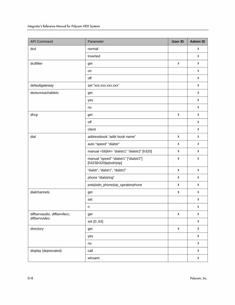
Integrator’s Reference Manual for Polycom HDX Systems
D–8 Polycom, Inc.
dcd normal 3
Inverted 3
dcdfilter get 3 3
on 3
off 3
defaultgateway set “xxx.xxx.xxx.xxx” 3
destunreachabletx get 3
yes 3
no 3
dhcp get 3 3
off 3
client 3
dial addressbook “addr book name” 3 3
auto “speed” “dialstr” 3 3
manual <56|64> “dialstr1” “dialstr2” [h320] 3 3
manual “speed” “dialstr1” [“dialstr2”] [h323|h320|ip|isdn|sip]
3 3
“dialstr”, “dialstr1”, “dialstr2” 3 3
phone “dialstring” 3 3
pots|isdn_phone|sip_speakerphone 3 3
dialchannels get 3 3
set 3
n 3
diffservaudio, diffservfecc, diffservvideo
get 3 3
set {0..63} 3
directory get 3 3
yes 3
no 3
display (deprecated) call 3
whoami 3
API Command Parameter User ID Admin ID

Secure RS-232 Interface API Permissions
Polycom, Inc. D–9
displaygraphics get 3 3
yes 3
no 3
displayipext get 3 3
yes 3
no 3
displayparams 3
dns get 3
{1..4} 3
set “xxx.xxx.xxx.xxx” 3
dsr get 3 3
normal 3
inverted 3
dsranswer get 3 3
on 3
off 3
dtr get 3 3
normal 3
inverted 3
on 3
dualmonitor get 3 3
yes 3 3
no 3 3
dynamicbandwidth get 3 3
yes 3
no 3
e164ext get 3 3
set 3
“e.164name” 3
echo “string” 3
API Command Parameter User ID Admin ID
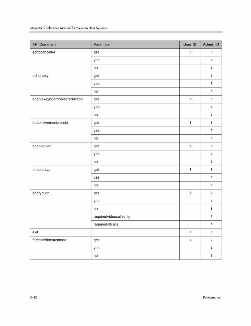
Integrator’s Reference Manual for Polycom HDX Systems
D–10 Polycom, Inc.
echocanceller get 3 3
yes 3
no 3
echoreply get 3
yes 3
no 3
enablekeyboardnoisereduction get 3 3
yes 3
no 3
enablelivemusicmode get 3 3
yes 3
no 3
enablepvec get 3 3
yes 3
no 3
enablersvp get 3 3
yes 3
no 3
encryption get 3 3
yes 3
no 3
requiredvideocallsonly 3
requiredallcalls 3
exit 3 3
farcontrolnearcamera get 3 3
yes 3
no 3
API Command Parameter User ID Admin ID

Secure RS-232 Interface API Permissions
Polycom, Inc. D–11
farnametimedisplay get 3 3
on 3
off 3
15|30|60|120 3
flash callid 3 3
duration 3 3
gaddrbook all 3 3
batch {0..59} 3 3
batch define “start_no” “stop_no” 3 3
search “pattern” “count” 3 3
letter {a..z} 3 3
range “start_no” “stop_no” 3 3
refresh 3 3
gatekeeperip get 3
set “xxx.xxx.xxx.xxx” 3
gatewayareacode get 3 3
set “areacode” 3
gatewaycountrycode get 3 3
set “countrycode” 3
gatewayext get 3 3
set “extension” 3
gatewaynumber get 3 3
set “number” 3
gatewaynumbertype get 3 3
did 3
number+extension 3
gatewayprefix get “valid speed” 3 3
set “value” 3
gatewaysetup 3 3
API Command Parameter User ID Admin ID

Integrator’s Reference Manual for Polycom HDX Systems
D–12 Polycom, Inc.
gatewaysuffix get “valid speed” 3 3
set “value” 3
gendial {0..9} 3 3
# 3 3
* 3 3
generatetone on 3 3
off 3 3
get screen 3
getcallstate 3 3
getconfiguredipaddress 3
h239enable get 3 3
yes 3
no 3
h323name get 3 3
set “H.323name” 3
h331audiomode get 3 3
g729 | g728 | g711u | g711a | g722-56 | g722-48 | g7221-16 | g7221-24 | g7221-32 | siren14 | siren14stereo
3
off 3
h331dualstream get 3 3
on 3
off 3
h331framerate get 3 3
30|15|10|7.5 3
h331videoformat get 3 3
fcif 3
h331videoprotocol get 3 3
h264|h263+|h263|h261 3
API Command Parameter User ID Admin ID

Secure RS-232 Interface API Permissions
Polycom, Inc. D–13
hangup phone 3 3
video 3 3
all 3 3
history 3 3
homecallquality get 3 3
yes 3
no 3
homerecentcalls get 3 3
yes 3
no 3
homesystem get 3 3
yes 3
no 3
homesystemname get 3 3
yes 3
no 3
hostname get 3 3
set “hostname” 3
icmpoutpacketrate get 3
set integer value 3
ignoreredirect get 3
yes 3
no 3
incompleterevocationcheck get 3
yes 3
no 3
ipaddress
Note: set is not allowed while in a call.
get 3 3
set “xxx.xxx.xxx.xxx” 3
ipdialspeed get “valid speed” 3 3
set “valid speed” <on, off> 3
API Command Parameter User ID Admin ID

Integrator’s Reference Manual for Polycom HDX Systems
D–14 Polycom, Inc.
ipisdninfo get 3 3
both 3
ip-only 3
isdn-only 3
none 3
ipprecaudio, ipprecfecc, ipprecvideo
get 3 3
set 3
ipstat 3
ipv6addrmode get 3
client 3
manual 3
off 3
ipv6defaultgateway get 3
set <IPv6 default gateway> 3
ipv6globaladdress get 3
set <ipv6 global address> 3
ipv6linklocal get 3
set <ipv6 link local address> 3
ipv6sitelocal get 3
set <ipv6 site local address> 3
isdnareacode get 3 3
set “area code” 3
isdncountrycode get 3 3
set “country code” 3
isdndialingprefix get 3 3
set “isdn prefix” 3
isdndialspeed get “valid speed” 3 3
set “valid speed” <on, off> 3
isdnnum
Note: set is not allowed while in a call.
get 1b1|1b2|2b1|2b2|3b1|3b2|4b1|4b2 3 3
set 1b1|1b2|2b1|2b2|3b1|3b2|4b1|4b2 3
API Command Parameter User ID Admin ID

Secure RS-232 Interface API Permissions
Polycom, Inc. D–15
isdnswitch
Note: set is not allowed while in a call.
get 3
pt-to-pt_at&t_5_ess|multipoint_at&t_5_ess|ni-1|nortel_dms-100|standard_etsi_euro-isdn|ts-031|ntt_ins-64
3
keypadaudioconf get 3 3
yes 3 3
no 3 3
language get 3 3
set 3
lanport
Note: set is not allowed while in a call.
get 3
10, 10hdx, 10fdx, 100, 100hdx, 100fdx 3
ldapauthenticationtype get 3
set 3
anonymous 3
basic 3
ntlm 3
ldapbasedn get 3
set “base dn” 3
ldapbinddn get 3
set “bind dn” 3
ldapdirectory get 3 3
yes 3
no 3
ldapntlmdomain get 3
set “domain” 3
ldappassword set <ntlm|basic> [“password”] disabled disabled
ldapserveraddress get 3
set “address” 3
ldapserverport get 3
set 3
API Command Parameter User ID Admin ID

Integrator’s Reference Manual for Polycom HDX Systems
D–16 Polycom, Inc.
ldapsslenabled get 3
set [on, off] 3
ldapusername get 3
set “user name” 3
linestate get 3 3
register 3 3
unregister 3 3
listen video 3 3
phone 3 3
sleep 3 3
localdatetime get 3 3
yes 3
no 3
loginwindowduration get 3
set 3
marqueedisplaytext get 3 3
set “text” 3
maxgabinternationalcallspeed get 3 3
set “valid speed” 3
maxgabinternetcallspeed get 3 3
set “valid speed” 3
maxgabisdncallspeed get 3 3
set “valid speed” 3
maxtimeincall get 3 3
set {0..999} 3
mcupassword “password” 3 3
meetingpassword set “password” 3 3
monitor1screensaveroutput get 3 3
black 3
no_signal 3
API Command Parameter User ID Admin ID

Secure RS-232 Interface API Permissions
Polycom, Inc. D–17
monitor2screensaveroutput get 3 3
black 3
no_signal 3
mpautoanswer get 3 3
yes 3
no 3
donotdisturb 3
mpmode get 3 3
auto 3 3
discussion 3 3
presentation 3 3
fullscreen 3 3
mtumode get 3 3
default 3
specify 3
mtusize get 3 3
660|780|900|1020|1140|1260|1500 3
mute <register|unregister> 3 3
near <get|on|off|toggle> 3 3
far get 3 3
muteautoanswer get 3 3
yes 3
no 3
natconfig get 3 3
auto 3
manual 3
off 3
nath323compatible get 3 3
yes 3
set 3
API Command Parameter User ID Admin ID

Integrator’s Reference Manual for Polycom HDX Systems
D–18 Polycom, Inc.
nearloop on 3 3
off 3 3
netstats {0..n} 3 3
nonotify callstatus 3 3
captions 3 3
linestatus 3 3
mutestatus 3 3
screenchanges 3 3
sysstatus 3 3
sysalerts 3 3
vidsourcechanges 3 3
notify notify 3 3
callstatus 3 3
captions 3 3
linestatus 3 3
mutestatus 3 3
screenchanges 3 3
sysstatus 3 3
sysalerts 3 3
vidsourcechanges 3 3
ntpmode get 3 3
auto 3
off 3
manual 3
ntpsecondaryserver get 3
set <“server name”|“xxx.xxx.xxx.xxx”> 3
ntpserver get 3
set <“server name”|“xxx.xxx.xxx.xxx”> 3
numdigitsdid get 3 3
{0..24} 3
API Command Parameter User ID Admin ID

Secure RS-232 Interface API Permissions
Polycom, Inc. D–19
numdigitsext get 3 3
{0..24} 3
oobcomplete 3
pause {0..65535} 3 3
phone clear 3 3
flash 3 3
peoplevideoadjustment normal 3
stretch 3
zoom 3
get 3 3
pip <get|on|off|camera|swap|register|unregister|location>
3 3
location <get|0|1|2|3> 3 3
popupinfo register 3
unregister 3
get 3
preset <register|unregister> 3 3
register get 3 3
far <go|set> <{0..15}> 3 3
near <go|set> <{0..99}> 3 3
pricallbycall get 3 3
set {0..31} 3
prichannel get all 3 3
get {1..n} 3 3
set all <on|off>} 3
set {1..n} <on|off> 3
pricsu get 3 3
internal 3
external 3
pridialchannels get 3 3
set {1..n} 3
API Command Parameter User ID Admin ID

Integrator’s Reference Manual for Polycom HDX Systems
D–20 Polycom, Inc.
priintlprefix get 3 3
set “prefix” 3
prilinebuildout get 3 3
set <0|-7.5|-15|-22.5> 3
set <0-133|134-266|267-399|400-533|534-665> 3
prilinesignal get 3 3
set <esf/b8zs|crc4/hdb3|hdb3> 3
prinumberingplan get 3 3
isdn 3
unknown 3
prioutsideline get 3 3
set “outside line” 3
priswitch get 3
set <att5ess | att4ess | norteldms ni2 | net5/ctr4 | nttins-1500 | ts-038>
3
reboot [y|now|n] 3 3
recentcalls 3
registerall 3
resetsystem deletesystemsettings 3
deletelocaldirectory 3
deletecdr 3
deletelogs 3
roomphonenumber get 3 3
set “number” 3
rs232 baud get 3 3
9600|14400|19200|38400|57600|115200 3
rs232port1 baud get 3 3
9600|14400|19200|38400|57600|115200 3
rs232 mode off 3
control disabled 3
API Command Parameter User ID Admin ID

Secure RS-232 Interface API Permissions
Polycom, Inc. D–21
rs232port1 mode off 3
control disabled 3
rs366dialing get 3 3
on 3
off 3
rt get 3 3
normal 3
inverted 3
rts get 3 3
normal 3
inverted 3
screen 3 3
register get 3 3
[register|unregister] 3 3
“screen name” 3 3
screencontrol enable <all|none|"screen_name"> 3
disable <all|none|"screen_name"> 3
serialnum 3 3
servervalidatepeercert get 3
yes 3
no 3
session name “session name” 3 3
find “session name” 3 3
sessionsenabled get 3
yes 3
no 3
setpassword admin room "currentacctpasswd" "newacctpasswd" 3
showpopup “text to display” 3
API Command Parameter User ID Admin ID

Integrator’s Reference Manual for Polycom HDX Systems
D–22 Polycom, Inc.
sleep 3 3
register 3 3
unregister 3 3
sleeptext get 3 3
set “text” 3
sleeptime get 3 3
0|1|3|15|30|60|120|
240|480
3
soundeffectsvolume get 3 3
set {0..10} 3 3
test 3 3
spidnum
Note:
set is not allowed while in a call.
get <all|1b1|1b2|2b1|2b2|3b1|3b2|4b1|4b2> 3 3
set <1b1|1b2|2b1|2b2|3b1|3b2|4b1|4b2> [“spid number”]
3
sslverificationdepth get 3
set 3
st get 3 3
normal 3
inverted 3
subnetmask
Note:
set is not allowed while in a call.
get 3 3
set “xxx.xxx.xxx.xxx” 3
sysinfo get 3 3
register 3 3
unregister 3 3
systemname get 3 3
set “system name” 3
systemsetting telnetenabled get 3
on 3
off 3
port24only 3
API Command Parameter User ID Admin ID

Secure RS-232 Interface API Permissions
Polycom, Inc. D–23
tcpports
Note:
set is not allowed while in a call.
get 3 3
set 3
techsupport “phone num” 3 3
teleareacode get 3 3
set “telephone_area_code” 3
telenumber get 3 3
set “telephone number” 3
timediffgmt get 3 3
{-12:00..+12:00} 3
typeofservice get 3 3
ipprecedence 3
diffserv 3
udpports
Note:
set is not allowed while in a call.
get 3 3
set [{1024..49150}] 3
unregisterall 3
usefixedports get 3 3
yes 3
no 3
usegatekeeper get 3 3
off 3
specify 3
auto 3
usepathnavigator get 3 3
always 3
never 3
required 3
useroompassword get 3
no 3
yes 3
API Command Parameter User ID Admin ID
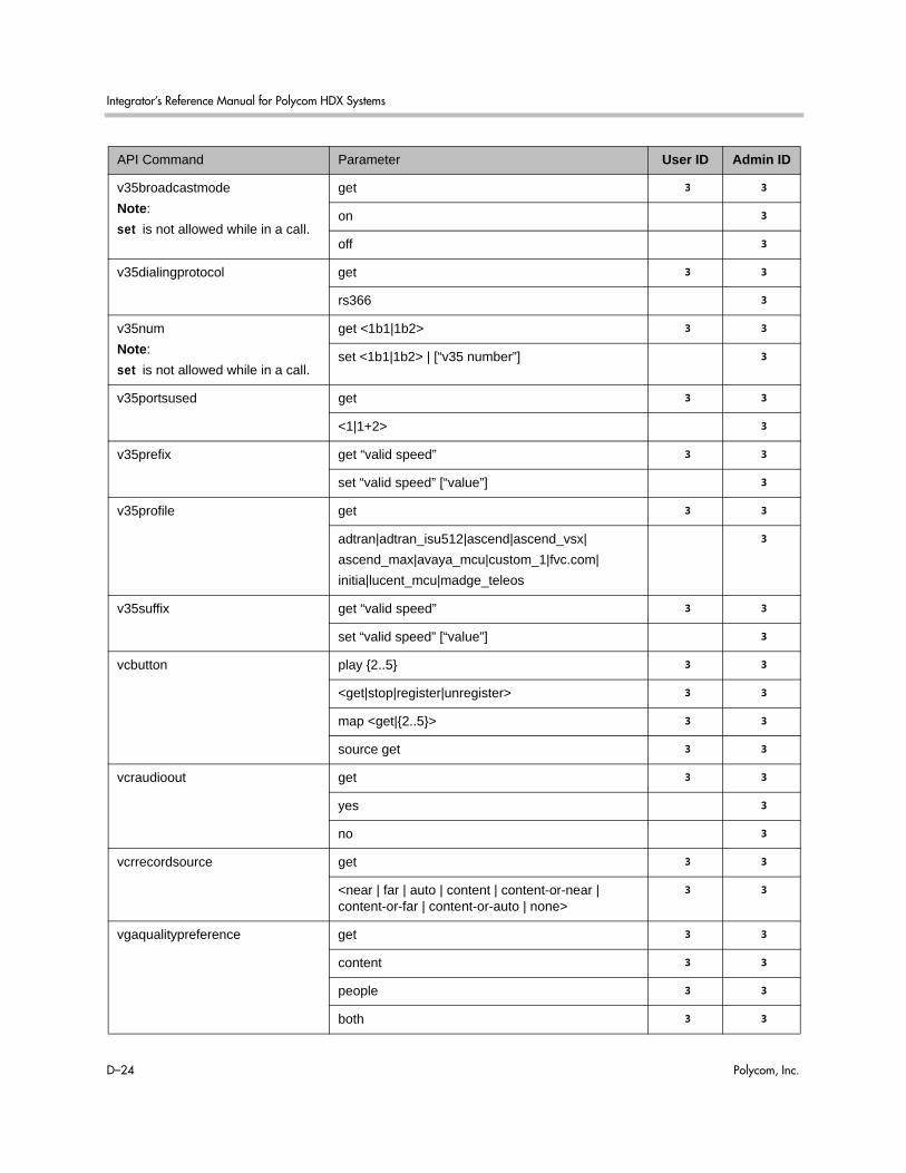
Integrator’s Reference Manual for Polycom HDX Systems
D–24 Polycom, Inc.
v35broadcastmode
Note:
set is not allowed while in a call.
get 3 3
on 3
off 3
v35dialingprotocol get 3 3
rs366 3
v35num
Note:
set is not allowed while in a call.
get <1b1|1b2> 3 3
set <1b1|1b2> | [“v35 number”] 3
v35portsused get 3 3
<1|1+2> 3
v35prefix get “valid speed” 3 3
set “valid speed” [“value”] 3
v35profile get 3 3
adtran|adtran_isu512|ascend|ascend_vsx|
ascend_max|avaya_mcu|custom_1|fvc.com|
initia|lucent_mcu|madge_teleos
3
v35suffix get “valid speed” 3 3
set “valid speed” [“value”] 3
vcbutton play {2..5} 3 3
<get|stop|register|unregister> 3 3
map <get|{2..5}> 3 3
source get 3 3
vcraudioout get 3 3
yes 3
no 3
vcrrecordsource get 3 3
<near | far | auto | content | content-or-near | content-or-far | content-or-auto | none>
3 3
vgaqualitypreference get 3 3
content 3 3
people 3 3
both 3 3
API Command Parameter User ID Admin ID

Secure RS-232 Interface API Permissions
Polycom, Inc. D–25
videocallorder <isdn|h323|sip|gateway323> <1|2|3|4> 3
voicecallorder <isdn_phone|pots> <1|2> 3
volume get 3 3
set 3
up 3
down 3
register 3
unregister 3
range 3
vortex <0|1> mute <on|off> disabled disabled
<0|1> forward “vortex_macro” disabled disabled
waitfor <systemready|callcomplete> 3 3
wake 3 3
wanipaddress get 3 3
set “xxx.xxx.xxx.xxx” 3
webport get 3
set 3
whitelistenabled get 3
yes 3
no 3
API Command Parameter User ID Admin ID

Integrator’s Reference Manual for Polycom HDX Systems
D–26 Polycom, Inc.
Polycom, Inc. E–1
ECategorical List of API Commands
You can view the table of contents for this book to see an alphabetical list of available API commands. These commands are categorized into the following sections:• Local Directory Commands on page E-2• Call Function Commands on page E-2• Conference Setting Commands on page E-3• Chair Control Commands on page E-4• Global Services Commands on page E-4• LAN, WAN, and IP Commands on page E-5• H320, POTS and Miscellaneous Network Commands on page E-7• Video and Audio Commands on page E-9• Registration Commands on page E-11• System Commands on page E-11• User Interface and System Display/Sound Commands on page E-12• Miscellaneous Commands on page E-13
Integrator’s Reference Manual for Polycom HDX Systems
E–2 Polycom, Inc.
Local Directory Commands• abk (deprecated) on page 4-9 (all Polycom HDX system versions)• addrbook on page 4-12 (Polycom HDX system versions 2.5 and later)
Call Function Commands
Calling Commands• answer on page 4-28 • dial on page 4-95 • flash on page 4-135• gendial on page 4-154 • gendialtonepots (deprecated) on page 4-155 • hangup on page 4-176 • phone on page 4-265
Call Status Request• advnetstats on page 4-15• callinfo on page 4-61 • getcallstate on page 4-158 • netstats on page 4-249
Call Logging Data• callstats on page 4-64 • calldetail on page 4-59 • calldetailreport on page 4-60 • display (deprecated) on page 4-102 • recentcalls on page 4-283
Call Registrations• callstate on page 4-62 • listen on page 4-225 • nonotify on page 4-250 • notify on page 4-251

Categorical List of API Commands
Polycom, Inc. E–3
Call Account Settings• requireacctnumtodial on page 4-288 • setaccountnumber on page 4-304• validateacctnum on page 4-347
Call Preference Settings• maxtimeincall on page 4-232• videocallorder on page 4-355• voicecallorder on page 4-356
Conference Setting Commands
Conference Settings• autoanswer on page 4-34• autoshowcontent on page 4-35• basicmode on page 4-37• contentauto on page 4-84• dualmonitor on page 4-114• dynamicbandwidth on page 4-115• encryption on page 4-126• enablepvec on page 4-123• farcontrolnearcamera on page 4-133• h239enable on page 4-169 • mpautoanswer on page 4-239• mpmode on page 4-240• muteautoanswer on page 4-245• pip on page 4-266• vgaqualitypreference on page 4-354
Conference Password Settings• mcupassword on page 4-233 • meetingpassword on page 4-234

Integrator’s Reference Manual for Polycom HDX Systems
E–4 Polycom, Inc.
Chair Control Commands• chaircontrol on page 4-71
Global Services Commands
Calendar Commands• calendardomain on page 4-44 • calendarmeetings on page 4-45• calendarpassword on page 4-50• calendarplaytone on page 4-51• calendarregisterwithserver on page 4-52• calendarremindertime on page 4-53• calendarresource on page 4-54• calendarserver on page 4-55• calendarshowpvtmeetings on page 4-56• calendarstatus on page 4-57• calendaruser on page 4-58
GAB and GDS Commands• addressdisplayedingab on page 4-14 • gabk (deprecated) on page 4-136 • gabpassword on page 4-139 • gabserverip on page 4-140 • gaddrbook on page 4-141 • maxgabinternationalcallspeed on page 4-229 • maxgabinternetcallspeed on page 4-230 • maxgabisdncallspeed on page 4-231 • registerthissystem on page 4-285
GMS Commands• gmscity on page 4-160 • gmscontactemail on page 4-161 • gmscontactfax on page 4-162 • gmscontactnumber on page 4-163 • gmscontactperson on page 4-164
Categorical List of API Commands
Polycom, Inc. E–5
• gmscountry on page 4-165 • gmsstate on page 4-166 • gmstechsupport on page 4-167 • gmsurl on page 4-168
LDAP Commands• ldapauthenticationtype on page 4-214• ldapbasedn on page 4-215• ldapbinddn on page 4-216• ldapdirectory on page 4-217• ldapntlmdomain on page 4-218• ldappassword on page 4-219• ldapserveraddress on page 4-220• ldapserverport on page 4-221• ldapsslenabled on page 4-222• ldapusername on page 4-223
SNMP Commands• enablesnmp on page 4-125 • snmpadmin on page 4-310 • snmpcommunity on page 4-311 • snmpconsoleip on page 4-312 • snmplocation on page 4-313 • snmpsystemdescription on page 4-314 • snmptrapversion on page 4-315
OCS Commands• ocsdirectory on page 4-260
LAN, WAN, and IP Commands
H323 Commands• clientvalidatepeercert on page 4-73 • dynamicbandwidth on page 4-115 • e164ext on page 4-116
Integrator’s Reference Manual for Polycom HDX Systems
E–6 Polycom, Inc.
• enablersvp on page 4-124 • h323name on page 4-170 • ipdialspeed on page 4-194 • natconfig on page 4-246 • nath323compatible on page 4-247 • usepathnavigator on page 4-336
Gatekeeper Commands• gatekeeperip on page 4-144 • usegatekeeper on page 4-335
Gateway Commands• gatewayareacode on page 4-145 • gatewayareacode on page 4-145 • gatewayext on page 4-147 • gatewaynumber on page 4-148 • gatewaynumbertype on page 4-149 • gatewayprefix on page 4-150 • gatewaysetup on page 4-151• gatewaysuffix on page 4-152 • numdigitsdid on page 4-258 • numdigitsext on page 4-259
LAN and WAN Commands• defaultgateway on page 4-92 • dhcp on page 4-94 • dns on page 4-110 • getconfiguredipaddress on page 4-159• hostname on page 4-183 • ipv6addrmode on page 4-198• ipv6globaladdress on page 4-199 • ipv6defaultgateway on page 4-200 • ipv6linklocal on page 4-201 • ipv6sitelocal on page 4-202 • ipaddress on page 4-193 • ipstat on page 4-203• lanport on page 4-213 • subnetmask on page 4-321
Categorical List of API Commands
Polycom, Inc. E–7
• wanipaddress on page 4-363 • webport on page 4-365
Network and QoS Commands• destunreachabletx on page 4-93 • diffservaudio, diffservfecc, diffservvideo on page 4-100 • echoreply on page 4-119 • enablefirewalltraversal on page 4-120 • icmpoutpacketrate on page 4-185 • ignoreredirect on page 4-186 • ipprecaudio, ipprecfecc, ipprecvideo on page 4-197 • mtumode on page 4-242 • mtusize on page 4-243 • ntpmode on page 4-254 • ntpserver on page 4-256 • ntpsecondaryserver on page 4-255 • systemsetting telnetenabled on page 4-324• tcpports on page 4-325 • typeofservice on page 4-331 • udpports on page 4-332 • usefixedports on page 4-334 • webmonitoring on page 4-364
Network Security Commands• incompleterevocationcheck on page 4-192 • loginwindowduration on page 4-227 • servervalidatepeercert on page 4-301 • sessionsenabled on page 4-303• sslverificationdepth on page 4-320 • whitelistenabled on page 4-366
H320, POTS and Miscellaneous Network Commands
ISDN - Global Commands• areacode on page 4-29 • dialchannels on page 4-99

Integrator’s Reference Manual for Polycom HDX Systems
E–8 Polycom, Inc.
• isdnareacode on page 4-204 • isdncountrycode on page 4-205 • isdndialingprefix on page 4-206 • isdndialspeed on page 4-207 • isdnnum on page 4-209 • isdnswitch on page 4-210
ISDN - BRI Commands• bri1enable, bri2enable, bri3enable, bri4enable on page 4-38 • briallenable on page 4-39 • spidnum on page 4-317
ISDN - PRI Commands• pricallbycall on page 4-271 • prichannel on page 4-272 • pricsu on page 4-274• pridialchannels on page 4-275 • priintlprefix on page 4-276 • prilinebuildout on page 4-277 • prilinesignal on page 4-278 • prinumberingplan on page 4-279 • prioutsideline on page 4-280 • priswitch on page 4-281
V35 Commands• cts on page 4-88 • dcd on page 4-90 • dcdfilter on page 4-91 • dsr on page 4-111 • dsranswer on page 4-112 • dtr on page 4-113 • h331audiomode on page 4-171• h331dualstream on page 4-172 • h331framerate on page 4-173 • h331videoformat on page 4-174 • h331videoprotocol on page 4-175 • rs366dialing on page 4-295 • rt on page 4-296
Categorical List of API Commands
Polycom, Inc. E–9
• rts on page 4-297 • st on page 4-319 • v35broadcastmode on page 4-339 • v35dialingprotocol on page 4-340 • v35num on page 4-341 • v35portsused on page 4-343 • v35prefix on page 4-344 • v35profile on page 4-345 • v35suffix on page 4-346
POTS Commands• roomphonenumber on page 4-291 • teleareacode on page 4-327 • telenumber on page 4-328
Miscellaneous Network Commands• advnetstats on page 4-15 • linestate on page 4-224 • netstats on page 4-249 • nonotify on page 4-250 • notify on page 4-251
Video and Audio Commands
Audio Commands• audiometer on page 4-30 • audiotransmitlevel on page 4-32 • echocanceller on page 4-118 • enablekeyboardnoisereduction on page 4-121 • enablelivemusicmode on page 4-122 • mute on page 4-244 • nonotify on page 4-250 • notify on page 4-251 • soundeffectsvolume on page 4-316 • vcraudioout on page 4-351 • volume on page 4-357

Integrator’s Reference Manual for Polycom HDX Systems
E–10 Polycom, Inc.
• vortex on page 4-359
Content Commands• autoshowcontent on page 4-35 • camera on page 4-65 • contentauto on page 4-84 • vcbutton on page 4-348
Camera Control/Input Select Commands• camera on page 4-65 • farcontrolnearcamera on page 4-133 • preset on page 4-269
Camera Input Setting Commands• backlightcompensation on page 4-36 • camera on page 4-65 • cameradirection on page 4-69 • camerainput on page 4-70 • configparam on page 4-79 • nonotify on page 4-250 • notify on page 4-251
Monitor Video Output Setting Commands• configdisplay on page 4-77 • configpresentation on page 4-80 • contentsplash on page 4-85 • contentvideoadjustment on page 4-86 • dualmonitor on page 4-114 • monitor1 (deprecated) on page 4-235 • monitor1screensaveroutput on page 4-236 • monitor2 (deprecated) on page 4-237 • monitor2screensaveroutput on page 4-238 • numberofmonitors (deprecated) on page 4-257 • peoplevideoadjustment on page 4-264 • pip on page 4-266 • vcrrecordsource on page 4-352
Categorical List of API Commands
Polycom, Inc. E–11
Registration Commands• all register on page 4-19• all unregister on page 4-21 • audiotransmitlevel on page 4-32 • callstate on page 4-62 • camera on page 4-65 • chaircontrol on page 4-71 • configchange (deprecated) on page 4-76 • linestate on page 4-224 • listen on page 4-225 • mute on page 4-244 • nonotify on page 4-250 • notify on page 4-251 • pip on page 4-266 • preset on page 4-269 • registerall (deprecated) on page 4-284 • screen on page 4-298 • sysinfo on page 4-322 • unregisterall (deprecated) on page 4-333 • vcbutton on page 4-348 • volume on page 4-357
System Commands
System Setting Commands• allowabkchanges on page 4-22 • allowcamerapresetssetup on page 4-23 • allowdialing on page 4-24 • allowmixedcalls on page 4-25 • allowusersetup on page 4-26 • confirmdiradd on page 4-82 • confirmdirdel on page 4-83 • country on page 4-87 • daylightsavings on page 4-89 • gdsdirectory on page 4-153 • language on page 4-212 • remotemonenable on page 4-287

Integrator’s Reference Manual for Polycom HDX Systems
E–12 Polycom, Inc.
• rs232 baud, rs232port1 baud on page 4-292 • rs232 mode, rs232port1 mode on page 4-293 • setpassword on page 4-305 • sleeptext on page 4-308 • sleeptime on page 4-309 • systemname on page 4-323 • techsupport on page 4-326 • timediffgmt on page 4-330 • useroompassword on page 4-338
Query Commands for System Information• serialnum on page 4-300 • sysinfo on page 4-322 • version on page 4-353 • whoami on page 4-367
Diagnostic Commands• colorbar on page 4-75 • generatetone on page 4-156 • nearloop on page 4-248 • reboot on page 4-282
User Interface and System Display/Sound Commands
Sound Setting Commands• alertusertone on page 4-17 • alertvideotone on page 4-18 • keypadaudioconf on page 4-211
Display Setting Commands• directory on page 4-101 • displayglobaladdresses on page 4-104 • displaygraphics on page 4-105 • displayipext on page 4-106 • displayipisdninfo (deprecated) on page 4-107

Categorical List of API Commands
Polycom, Inc. E–13
• farnametimedisplay on page 4-134 • get screen on page 4-157 • homecallquality on page 4-178 • homemultipoint (deprecated) on page 4-179 • homerecentcalls on page 4-180 • homesystem on page 4-181 • homesystemname on page 4-182 • ipisdninfo on page 4-196 • localdatetime on page 4-226 • marqueedisplaytext on page 4-228 • popupinfo on page 4-268 • screen on page 4-298 • screencontrol on page 4-299 • showpopup on page 4-306
IR Emulation Commands and Control• button on page 4-40 • remotecontrol on page 4-286
Miscellaneous Commands• ! on page 4-7 • amxdd on page 4-27 • cmdecho on page 4-74 • displayparams on page 4-108 • echo on page 4-117 • exit on page 4-128 • exportdirectory on page 4-129 • exportprofile on page 4-131 • history on page 4-177 • importdirectory on page 4-187 • importprofile on page 4-190 • oobcomplete on page 4-262 • pause on page 4-263 • resetsystem on page 4-289 • session on page 4-302 • sleep on page 4-307 • telnetechoeol on page 4-329

Integrator’s Reference Manual for Polycom HDX Systems
E–14 Polycom, Inc.
• waitfor on page 4-361 • wake on page 4-362

Polycom, Inc. Index-1
Index
Symbols! command 4–7
Aabk (deprecated) command 4–9account number
command for requiring 4–288command for setting 4–304command for validating 4–347
adaptersaudio 2–54BNC to S-Video 2–18HDCI PowerCam Plus 2–35HDCI Sony 2–40HDCI Sony VISCA 2–39HDCI VISCA 2–36microphone 2–49null modem 2–62S-Video to RCA 2–19V.35/RS-449/RS-530 2–8
addrbook command 4–12address
LDAP server 4–220addressdisplayedingab command 4–14advnetstats command 4–15alertusertone command 4–17alertvideotone command 4–18all register command 4–19all unregister command 4–21allowabkchanges command 4–22allowcamerapresetssetup command 4–23allowdialing command 4–23, 4–24allowmixedcalls command 4–25allowusersetup command 4–26AMX, Device Discovery 4–27amxdd command 4–27answer command 4–28API
session command 4–302using over LAN 3–4
using over RS-232 3–1API resources 3–5
contact information 3–5controller code downloads 3–4Knowledge Base 3–5video test numbers 3–5
area codecommand for BRI 4–29command for gateway 4–145command for ISDN 4–204command for system 4–327
areacode command 4–29attenuator, subwoofer volume 2–58audio
cable 2–54, 2–55connector, balanced 2–57integration 1–21
audio mode, command for H.331 calls 4–171audio out, VCR 4–351audiometer command 4–30audiotransmitlevel command 4–32authentication type
LDAP server 4–214auto answer, command for multipoint 4–239auto mode, command for multipoint display
4–240autoanswer command 4–34
BB channel status messages B–1back panels C–1backlightcompensation command 4–36bandwidth 4–354base DN
LDAP server 4–215basicmode command 4–37baud rate, command to set RS-232 port 4–292bind DN
LDAP server 4–216BNC adapter 2–18

Integrator’s Reference Manual for Polycom HDX Systems
Index-2
BNC to S-Video cable 2–17BRI cable 2–5briallenable command 4–39brienable commands 4–38broadcaster setting 4–72broadcasting, V.35 command 4–339button command 4–40
Ccables
analog telephone 2–7audio 2–54, 2–55BNC 2–24BNC monitor 2–22BNC to S-Video 2–17BRI 2–5CAT 5e LAN 2–1Component A/V Monitor 2–26composite video 2–32DVI 2–21, 2–22, 2–23DVI Monitor 2–25DVI to VGA 2–16, 2–20HDCI 2–27, 2–30, 2–34, 2–35, 2–36, 2–37, 2–39,
2–40HDMI monitor 2–21HDX component video 2–24ISDN 2–5LAN 2–3microphone 2–48, 2–49, 2–51microphone host 2–46Polycom HDX component monitor 2–23POTS 2–7PowerCam break-out 2–42PowerCam control 2–43PowerCam Plus primary 2–33PowerCam primary 2–41PRI 2–5RCA 2–24RS-366 2–10, 2–11, 2–13RS-449 2–11RS-530 2–13serial 2–60S-Video 2–16V.35 2–9, 2–10VCR/DVD composite 2–31VISCA 2–43Vortex 2–56
calendardomain command 4–44calendarmeetings command 4–45calendarpassword command 4–50calendarplaytone command 4–51calendarregisterwithserver 4–52
calendarregisterwithserver command 4–52calendarremindertime command 4–53calendarresource command 4–54calendarserver command 4–55calendarshowpvtmeetings 4–56calendarshowpvtmeetings command 4–56call quality, command for access 4–178call speed
command for Internet 4–230command for ISDN 4–231international calls, maximum speed 4–229maximum command 4–229
call status, displaying B–1calldetail command 4–59calldetailreport command 4–60callinfo command 4–61callstate command 4–62callstats command 4–64camera command 4–65camera presets, command to allow 4–23cameradirection command 4–69camerainput command 4–70cameras, connecting
Polycom EagleEye 1080 camera 1–9PowerCam as main camera 1–12PowerCam as secondary camera 1–13, 1–14PowerCam Plus as main camera 1–15PowerCam Plus as second camera 1–16, 1–18Sony BRC-H700 PTZ camera 1–18Sony EVI-HD1 camera 1–9Sony PTZ camera 1–17Vaddio 300 PTZ camera 1–20Vaddio 70 and 100 PTZ camera 1–19
Canon PTZ camera 1–19chaircontrol command 4–71city, command for Global Management System
4–160clientvalidatepeercert command 4–73cmdecho command 4–74colorbar command 4–75command response syntax 4–3command, configuring parameters 4–79composite video cable 2–32configchange command 4–76configdisplay command 4–77configparam command 4–79configpresentation command 4–80configuration settings 4–79

Index
Index-3
configuring parameters 4–79confirmdiradd command 4–82confirmdirdel command 4–83connections, back panel C–1connectors
balanced audio 2–57subwoofer 2–58
contact information 3–5contact, command for Global Management
System 4–161, 4–164contentauto command 4–84contentsplash command 4–85contentvideoadjustment command 4–86control
flow 4–5controller code downloads 3–4conventions, syntax 4–2country code
command for gateway 4–146command for ISDN 4–205
country command 4–87country, command for Global Management
System 4–165Crestron systems 2–62, 3–4cts command 4–88
Ddate and time, command to display 4–226daylightsavings command 4–89dcd command 4–90dcdfilter command 4–91defaultgateway command 4–92delay between commands 4–5destunreachabletx command 4–93Device Discovery, AMX 4–27dhcp command 4–94dial command 4–95dialchannels command 4–99dialing
command for allowing 4–23, 4–24command for RS-366 4–295
dialing ordercommand for video calls 4–355command for voice calls 4–356
dialing prefixcommand for PRI international 4–276command for V.35 4–344
dialing speed
command for IP 4–194command for ISDN 4–207
dialing tones, generating 4–155diffservaudio command 4–100diffservfecc command 4–100diffservvideo command 4–100directory
command for allowing changes 4–22command for confirming additions 4–82command for confirming deletions 4–83
directory command 4–101discussion mode, command for multipoint
display 4–240display command 4–102displayglobaladdresses command 4–104displaygraphics command 4–105displayipext command 4–106displayipisdninfo command 4–107displayparams command 4–108dns command 4–110do not disturb setting
for multipoint calls 4–239for point-to-point calls 4–34
downloads, controller code 3–4dsr command 4–111dsranswer command 4–112DTMF dialing tones, generating 4–155dtr command 4–113dual stream setting, command for H.331 calls
4–172dualmonitor command 4–114DVI cable 2–20DVI to VGA cable 2–16dynamicbandwidth command 4–115
Ee164ext command 4–116echo command 4–117echocanceller command 4–118echoreply command 4–119ELMO PTZ camera 1–17email contact, command for Global Management
System 4–161enablefirewalltraversal command 4–120enablekeyboardnoisereduction command 4–121enablelivemusicmode command 4–122enablepvec command 4–123enablersvp command 4–124

Integrator’s Reference Manual for Polycom HDX Systems
Index-4
enablesnmp command 4–125encryption command 4–126exit command 4–128exportdirectory command 4–129exportprofile command 4–131extension, command for gateway 4–147
Ffarcontrolnearcamera command 4–133farnametimedisplay command 4–134fax, command for Global Management System
4–162firewall traversal, H.460 traversal 4–120flash command 4–135flow control 4–5frame rate, command for H.331 calls 4–173fullscreen mode, command for multipoint
display 4–240
Ggabk command 4–136gabpassword command 4–139gabserverip command 4–140gaddrbook 4–141gaddrbook command 4–141gatekeeper, command for mode 4–335gatekeeperip command 4–144gateway, command for default 4–92gatewayareacode command 4–145gatewaycountrycode command 4–146gatewayext command 4–147gatewaynumber command 4–148gatewaynumbertype command 4–149gatewayprefix command 4–150gatewaysetup command 4–151gatewaysuffix command 4–152GDS
command for display 4–104command for server 4–140password 4–139
gdsdirectory command 4–153gendial command 4–154gendialtonepots command 4–155generatetone command 4–156get screen command 4–157getcallstate command 4–158getconfiguredipaddress command 4–159
global directorydisplaying address in 4–14maximum call speed 4–229, 4–230, 4–231returning entries 4–136
Global Management Systemcommand for email 4–161command for support number 4–167
gmscity command 4–160gmscontactemail command 4–161gmscontactfax command 4–162gmscontactnumber command 4–163gmscontactperson command 4–164gmscountry command 4–165gmsstate command 4–166gmstechsupport command 4–167gmsurl command 4–168
HH.460 firewall traversal 4–120h239enable command 4–169h323name command 4–170h331audiomode command 4–171h331dualstream command 4–172h331framerate command 4–173h331videoformat command 4–174h331videoprotocol command 4–175hangup command 4–176HDCI analog camera cable 2–27HDCI camera break-out cable 2–30HDCI Polycom EagleEye 1080 Camera cable
2–37HDCI PowerCam 2–34HDCI PowerCam Plus adapter 2–35, 2–36, 2–39,
2–40history command 4–177history list 4–7home screen IP and ISDN information display
4–196homecallquality command 4–178homemultipoint command 4–179homerecentcalls command 4–180homesystem command 4–181homesystemname command 4–182hostname command 4–183
Iicmpoutpacketrate command 4–185icons, command for displaying 4–105
Index
Index-5
ignoreredirect command 4–186importdirectory command 4–187importprofile command 4–190incompleterevocationcheck command 4–192InstantDesigner, recommendation 1–25inverted signal
command for CTS 4–88command for DCD 4–90command for DSR 4–111command for DTR 4–113command for RT 4–296command for RTS 4–297command for ST 4–319
IP command for line state changes 4–224IP dialing speed 4–194IP information display on home screen 4–196ipaddress command 4–193ipdialspeed command 4–194ipisdninfo command 4–196ipprecaudio command 4–197ipprecfecc command 4–197ipprecvideo command 4–197ipstat command 4–203ipv6addrmode command 4–198ipv6defaultgateway command 4–200ipv6globaladdress command 4–199ipv6linklocal command 4–201ipv6sitelocal command 4–202IR codes C–3ISDN cable 2–5ISDN command for line state changes 4–224ISDN dialing speed 4–207ISDN information display on home screen 4–196isdnareacode command 4–204isdncountrycode command 4–205isdndialingprefix command 4–206isdndialspeed command 4–207isdnnum command 4–209isdnswitch command 4–210
Kkeypadaudioconf command 4–211Knowledge Base 3–5
LLAN cable 2–3LAN CAT 5e cable 2–1language command 4–212
lanport command 4–213LDAP
SSL encryption state 4–222LDAP server
address 4–220authentication type 4–214base DN 4–215bind DN 4–216password 4–219port 4–221
ldapauthenticationtype command 4–214ldapbasedn command 4–215ldapbinddn command 4–216ldapdirectory command 4–217ldapntlmdomain command 4–218ldappassword command 4–219ldapserveraddress command 4–220ldapserverport command 4–221ldapsslenabled command 4–222ldapusername command 4–223linestate command 4–224listen command 4–225localdatetime command 4–226loginwindow command 4–227
Mmarqueedisplaytext command 4–228maxgabinternationalcallspeed command 4–229maxgabinternetcallspeed command 4–230maxgabisdncallspeed command 4–231maxtimeincall command 4–232mcupassword command 4–233microphone host cable 2–46monitor
command for split-screen 4–114content presentation 4–80
monitor1 command 4–235monitor1screensaveroutput command 4–236,
4–238monitor2 command 4–237mpautoanswer command 4–239mpmode command 4–240mtumode command 4–242mtusize command 4–243multipoint button, command for access 4–179multipoint display mode, command for setting
4–240mute command 4–244

Integrator’s Reference Manual for Polycom HDX Systems
Index-6
muteautoanswer command 4–245
Nnatconfig command 4–246nath323compatible command 4–247nearloop command 4–248netstats command 4–249nonotify command 4–250notifications, line state changes 4–224notify command 4–251ntpmode command 4–254ntpsecondaryserver command 4–255ntpserver command 4–256null modem adapter 2–62numberofmonitors command 4–257numdigitsdid command 4–258numdigitsext command 4–259
Ooobcomplete command 4–262
Pparameters, configuring 4–79parameters, setting multiple 4–79password
command for GDS 4–139LDAP server 4–219remote access 4–338room 4–338
PathNavigator, command for multipoint calls 4–336
pause command 4–263People 2–45People+Content, H.239 command 4–169peoplevideoadjustment command 4–264phone call, command to answer 4–28phone command 4–265phone flash command 4–135phone number
command for Global Management System contact 4–163
command for Global Management System technical support 4–326
command for room 4–291command for system 4–328
pip command 4–266polling 4–5Polycom 2–4, 2–15, 2–50
Polycom CMA system, command for multipoint calls 4–336
Polycom EagleEye 1080 Camera cable 2–37popupinfo command 4–268port
LDAP server 4–221port settings
command for fixed 4–334command for LAN 4–213command for TCP 4–325command for the system’s Web interface 4–365command for UDP 4–332
POTS cable 2–7POTS line, generating DTMF dialing tones 4–155PowerCam
break-out cable 2–42connecting as main camera 1–12connecting as secondary camera 1–13, 1–14control cable 2–43primary cable 2–41
PowerCam HDCI 2–34PowerCam Plus
connecting as main camera 1–15connecting as second camera 1–16, 1–18primary cable 2–33
PowerCam Plus HDCI adapter 2–35, 2–36, 2–39, 2–40
presentation mode, command for multipoint display 4–240
preset command 4–269PRI cable 2–5PRI channel information 4–272PRI port assignments 2–6pricallbycall command 4–271prichannel command 4–272pricsu command 4–274pridialchannels command 4–275priintlprefix command 4–276prilinebuildout command 4–277prilinesignal command 4–278prinumberingplan command 4–279prioutsideline command 4–280priswitch command 4–281processing
commands 4–5PVEC, command to enable 4–123
Qquality preference 4–354

Index
Index-7
RRCA adapter 2–19ReadiManager, command for multipoint calls
4–336reboot command 4–282recent calls button, command for access 4–180recentcalls command 4–283registerall command 4–284registerthissystem command 4–285registrations 4–5remote control IR codes C–3remotecontrol command 4–286remotemonenable command 4–287requireacctnumtodial command 4–288resetsystem command 4–289resources, API 3–5response
syntax 4–3restarting, commands that restart the system
without a prompt 4–5room design A–1room layout examples 1–1–1–3roomphonenumber command 4–291RS-232
interfaceconfiguring 3–1starting an API session 3–3
rs232 baud command 4–292rs232 mode command 4–293rs232port1 baud command 4–292rs232port1 mode command 4–293RS-366 cable 2–10, 2–11, 2–13rs366dialing command 4–295RS-449 cable 2–11RS-530 cable 2–13RSVP, command to enable 4–124rt command 4–296rts command 4–297
Sscreen command 4–298screen saver setting 4–236, 4–238screencontrol command 4–299Secure RS-232 Interface API Permissions D–1sending commands
not during call establishment 4–5serial
cable 2–60serialnum command 4–300server
command for DNS 4–110command for GDS 4–140command for NTP 4–256
servervalidatepeercert command 4–301session command 4–302sessionsenabled command 4–303setaccountnumber command 4–304setpassword command 4–305showpopup command 4–306sleep command 4–307sleeptext command 4–308sleeptime command 4–309SNMP, command for enabling 4–125snmpadmin command 4–310snmpcommunity command 4–311snmpconsoleip command 4–312snmplocation command 4–313snmpsystemdescription command 4–314snmptrapversion command 4–315soundeffectsvolume command 4–316SoundStructure
connecting 1–26speaker test, command for 4–156spidnum command 4–317SSL encryption state
LDAP 4–222sslverificationdepth command 4–320st command 4–319statistics
command for advanced network 4–15command for IP 4–203command for network 4–249
status messages, B channel B–1status notifications, command for registering
4–322STD code, command for ISDN 4–204subnetmask command 4–321subwoofer volume attenuator 2–58S-Video
adapter 2–18, 2–19cable 2–16, 2–17
syntaxcommand response 4–3conventions 4–2
sysinfo command 4–322

Integrator’s Reference Manual for Polycom HDX Systems
Index-8
system button, command for access 4–181systemname command 4–323systemsetting telnetenabled command 4–324
Ttcpports command 4–325technical support 3–5technical support, command for Global
Management System 4–167techsupport command 4–326teleareacode command 4–327telenumber command 4–328Telnet session 3–4telnetechoeol command 4–329test numbers, video 3–5time in call, command 4–232timediffgmt command 4–330tones, command for testing 4–156typeofservice command 4–331
Uudpports command 4–332unregisterall command 4–333URL, command for Global Management System
4–168usefixedports command 4–334usegatekeeper command 4–335usepathnavigator command 4–336user settings, command for access 4–26useroompassword command 4–338
VV.35 cable 2–9, 2–10V.35/RS-449/RS-530 adapter 2–8v35broadcastmode command 4–339v35dialingprotocol command 4–340v35num command 4–341v35portsused command 4–343v35prefix command 4–344v35profile command 4–345v35suffix command 4–346validateacctnum command 4–347vcbutton command 4–348VCR audio out, command for controlling 4–351VCR/DVD composite cable 2–31vcraudioout command 4–351vcrrecordsource command 4–352
version command 4–353VGA
cable 2–20vgaqualitypreference
command for video calls 4–354vgaqualitypreference command 4–354Video 2–16video call, command to answer 4–28video integration 1–5video protocol, command for H.331 calls 4–175video quality 4–354video test numbers 3–5videocallorder command 4–355VISCA cable 2–43Visual Concert
command for controlling 4–348voicecallorder command 4–356volume command 4–357Vortex
cable 2–56connecting 1–25
vortex command 4–359
Wwaitfor command 4–361wanipaddress command 4–363webmonitoring command 4–364webport command 4–365whitelistenabled command 4–366whoami command 4–367