integration system of automatic identification … · integration system of automatic...
TRANSCRIPT
Jurnal Mekanikal
June 2015, Vol 38, 32-45
32
INTEGRATION SYSTEM OF AUTOMATIC IDENTIFICATION
SYSTEM AND RADAR FOR PORT TRAFFIC MANAGEMENT
NurAireenAmran1,, Jaswar Koto*
,1,2, AdiMaimun
1
1Faculty of Mechanical Engineering,
UniversitiTeknologi Malaysia,
81310, UTM JohorBahru,
Malaysia
2Ocean and Aerospace Research Institute,
Pekanbaru, Riau
Indonesia
ABSTRACT
In Vessel Traffic System, AIS can detect a larger number of targets without considering the
shadow effect and can provide more voyage information for port center. For radar system
can detect target actively even buoys or rock no matter ship size or fitted equipment. But even
radar can detect all targets, it is cannot give full information as AIS. AIS can give full
information such as types of ship, size, name, MMSI number and etc. AIS and radar system is
very important in the VTS to control ship in and out at the port area. They have to use two
different computers, which is one computer for AIS and another computer is for radar
systems.By integrating AIS and radar, the officer can control port with more accurate and
systematic. This paper will focus on integration of AIS and Radar for managing the
movement of vessels in port for safety purpose by taking Port Tanjung Pelepas as a case
study.
Keywords:Automatic Identification System, Radar, Integration
NOMENCLATURES
AIS Automatic Identification System
PTP Port Tanjung Palepas
VTS Vessel Traffic System
IMO International Maritime Organization
MMSI Maritime Mobile Service Identity
1.0 INTRODUCTION
In VTS, they are using AIS or known as an Automatic Identification System and radar
systems to control ship in and out at the port area. The function of AIS is used to identify and
locating the vessel by electronic exchange data either with nearby ships or VTS stations.
Besides that, AIS also can detect a larger number of targets without considering the shadow
effect and can provide more voyage information for Port traffic Management.
_________________________________ *Corresponding Authors: [email protected]
Jurnal Mekanikal June 2015
33
Even though AIS can give full information to VTS, but still the AIS cannot replace
RADAR system. The RADAR is for vessel which is not fitted AIS in their vessel. The benefit
of a RADAR system is can detect targets actively even buoys or rock no matter ship size or
fitted to any equipment [1]. Even though the RADAR system can detect all targets, but
RADAR system cannot give full information such as size of ship, name, MMSI and IMO
number.
Therefore, the port traffic management required to use both of this system to prevent the
ship from collision, including a ship colliding with a fishing boat. This is because fishing
boats also are using a port area that obstructs ship moving and increases navigation risk.
From AIS information, these kinds of situation cannot be found so that the port traffic
management officer cannot sound collision warning to the related ships.
In effect of that, it is difficult for port traffic officers to look out AIS and RADAR system
in two different computers at the same time. It is can be attributed to human error on
navigational faults due to incorrect judgment of ship movement by the port officer [1]. By
integrating of AIS and RADAR system, it is much easier for port officers to look out and
control the situation in the port area.
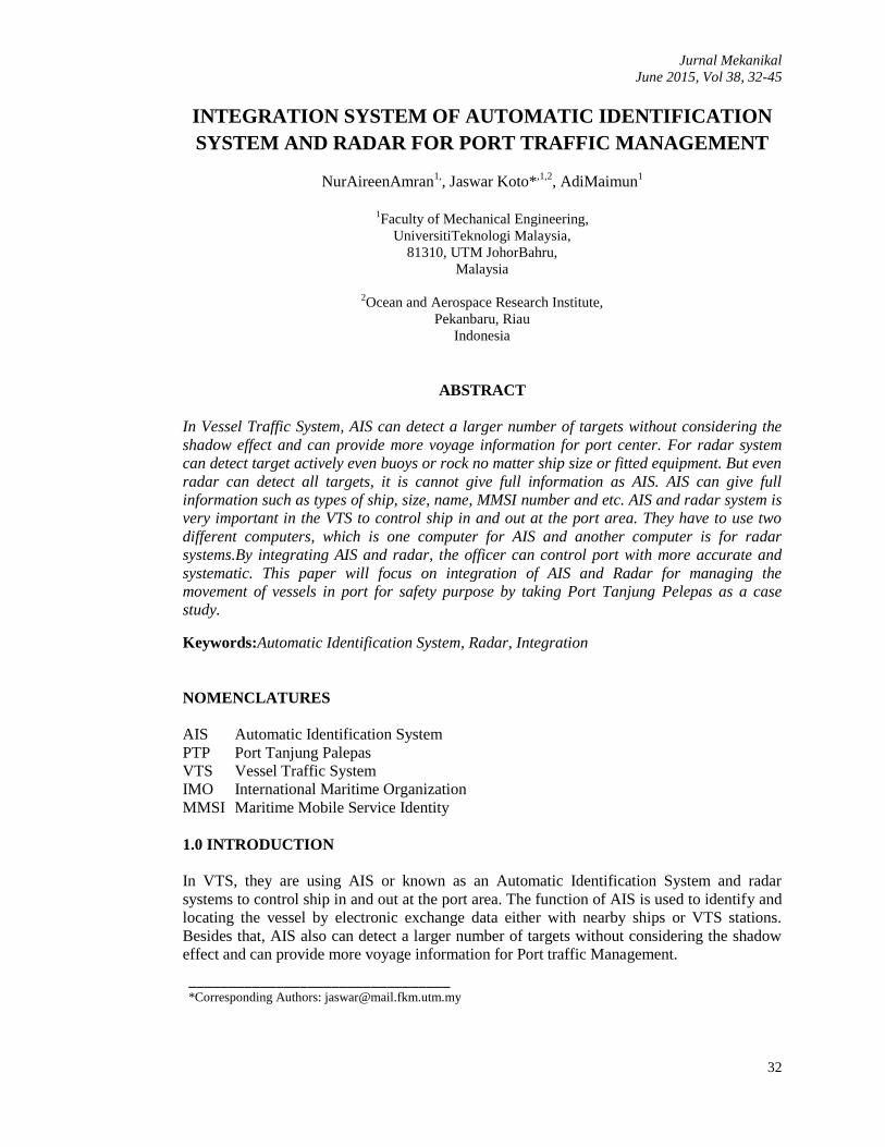
The port area for this project is focused on Port Tanjung Pelepas, which is located in the
Strait of Malacca and the most important channel in the world that connecting the Indian
Ocean with South China Sea and the Pacific Ocean as shown in Figure 1.In PTP, they are still
using Automatic Identification System and RADAR system with separate computer.
Therefore, this study focuses on the combination of AIS and RADAR system for safety and
improvement of vessel movement in and out of the port marine transportation system. In this
project also was proposed the system and tested at PTP as a study case.
Figure 1: Port Tanjung Pelepas [2].
Jurnal Mekanikal June 2015
34
2.0 PRINCIPLE THEORY
2.1 Speed of Ship
Speed of ship can be determined by using basic rules of speed which is distance divided by
time. The unit can be in m/s or in knot.
Speed =
(1)
where,
distance is distance of ship move from one point to another point, time is Time taken of
ship move from one point to another point and 1 knot is 0.5144 m/s
2.2 Actual Distance between Ships
For the actual distance between ships, it can be determined by using Haversine formulation.
The Haversine formula expressed in terms of a two-argument inverse tangent function to
calculate the actual distance between two points on the Earth as follows:
(2)
where,
= radius of the earth (6373 km)
= 2. a .tan 2 ( , )
= (sin (
))
2 + cos (lat1) .cos (lat2) . (sin (
))
2
Δlat = lat2 – lat1
Δlong = long2 – long1
3.0 AUTOMATIC IDENTIFICATION SYSTEM
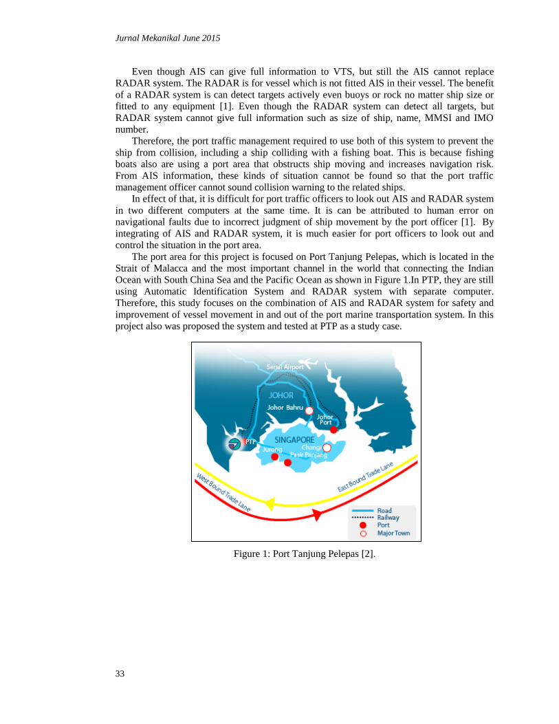
In this research, data was extracted from the AIS station of Joint International Research
Center on Safety Navigation. They have seven locations of AIS as showed in Figure 2 which
is station A (P23, UTM), station B (Belakang Padang), station C (Batu Ampar), station D
(Politek Negeri Batam), station E (Karimun), station F (Bintan) and station G (Bengkalis).
Jurnal Mekanikal June 2015
35
Figure 2: Location of AIS receiver [3]
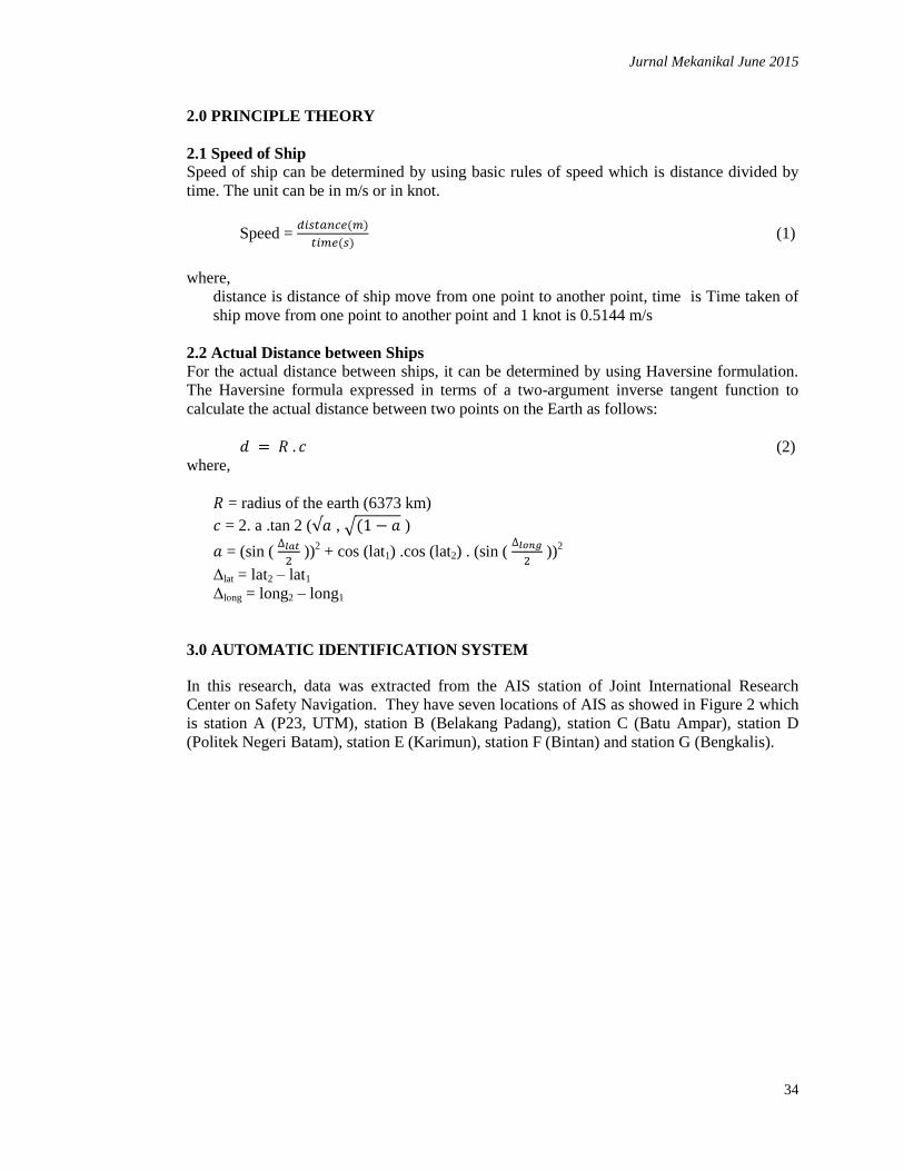
2.1 Station A (P23, UTM)
Station A is located in P23, UTM, Malaysia as shown in Figure.3. The position of this station
is at 1.56335 North and 103.64239 East, elevation: 38.6m [3].
Figure 3: AIS antenna installed at P23, Faculty Mechanical Engineering, Universiti
Teknologi Malaysia
Jurnal Mekanikal June 2015
36
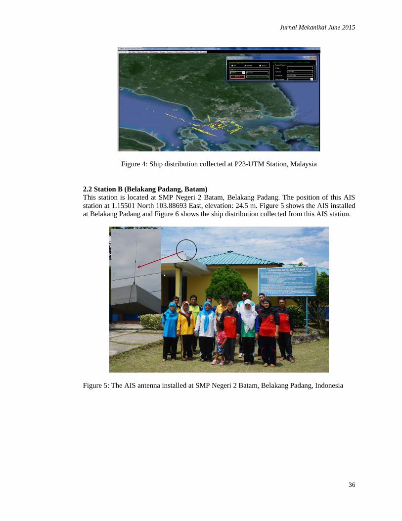
Figure 4: Ship distribution collected at P23-UTM Station, Malaysia
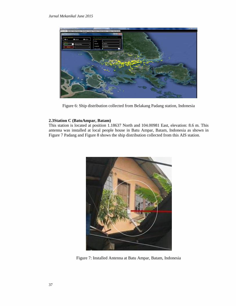
2.2 Station B (Belakang Padang, Batam)
This station is located at SMP Negeri 2 Batam, Belakang Padang. The position of this AIS
station at 1.15501 North 103.88693 East, elevation: 24.5 m. Figure 5 shows the AIS installed
at Belakang Padang and Figure 6 shows the ship distribution collected from this AIS station.
Figure 5: The AIS antenna installed at SMP Negeri 2 Batam, Belakang Padang, Indonesia
Jurnal Mekanikal June 2015
37
Figure 6: Ship distribution collected from Belakang Padang station, Indonesia
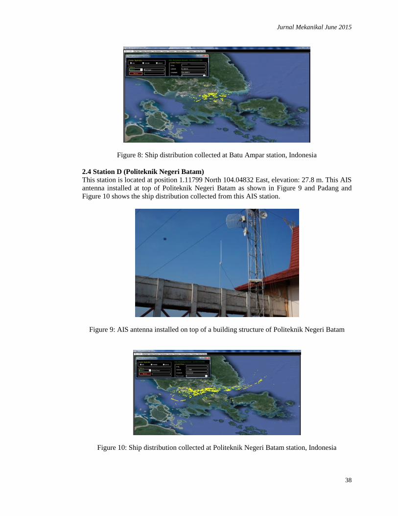
2.3Station C (BatuAmpar, Batam)
This station is located at position 1.18637 North and 104.00981 East, elevation: 8.6 m. This
antenna was installed at local people house in Batu Ampar, Batam, Indonesia as shown in
Figure 7 Padang and Figure 8 shows the ship distribution collected from this AIS station.
Figure 7: Installed Antenna at Batu Ampar, Batam, Indonesia
Jurnal Mekanikal June 2015
38
Figure 8: Ship distribution collected at Batu Ampar station, Indonesia
2.4 Station D (Politeknik Negeri Batam)
This station is located at position 1.11799 North 104.04832 East, elevation: 27.8 m. This AIS
antenna installed at top of Politeknik Negeri Batam as shown in Figure 9 and Padang and
Figure 10 shows the ship distribution collected from this AIS station.
Figure 9: AIS antenna installed on top of a building structure of Politeknik Negeri Batam
Figure 10: Ship distribution collected at Politeknik Negeri Batam station, Indonesia
Jurnal Mekanikal June 2015
39
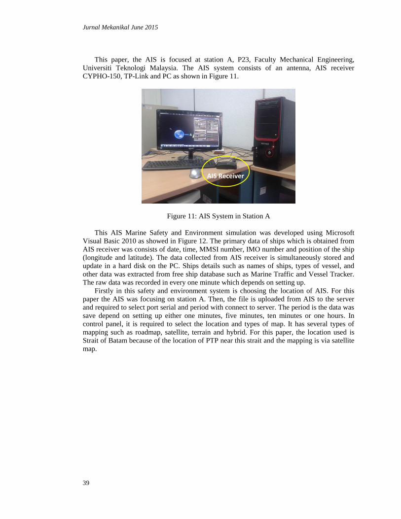
This paper, the AIS is focused at station A, P23, Faculty Mechanical Engineering,
Universiti Teknologi Malaysia. The AIS system consists of an antenna, AIS receiver
CYPHO-150, TP-Link and PC as shown in Figure 11.
Figure 11: AIS System in Station A
This AIS Marine Safety and Environment simulation was developed using Microsoft
Visual Basic 2010 as showed in Figure 12. The primary data of ships which is obtained from
AIS receiver was consists of date, time, MMSI number, IMO number and position of the ship
(longitude and latitude). The data collected from AIS receiver is simultaneously stored and
update in a hard disk on the PC. Ships details such as names of ships, types of vessel, and
other data was extracted from free ship database such as Marine Traffic and Vessel Tracker.
The raw data was recorded in every one minute which depends on setting up.
Firstly in this safety and environment system is choosing the location of AIS. For this
paper the AIS was focusing on station A. Then, the file is uploaded from AIS to the server
and required to select port serial and period with connect to server. The period is the data was
save depend on setting up either one minutes, five minutes, ten minutes or one hours. In
control panel, it is required to select the location and types of map. It has several types of
mapping such as roadmap, satellite, terrain and hybrid. For this paper, the location used is
Strait of Batam because of the location of PTP near this strait and the mapping is via satellite
map.
AIS Receiver

Jurnal Mekanikal June 2015
40
Figure 12: The AIS Marine Safety and Environment Simulation
This system can be used for navigation tracking and collision prevention using GPS and
AIS. The marine navigation tracking system will show the position of a ship on the map
which is linked to a Google map and denoted with yellow color as shown in Figure 13. The
full detail of ship can be identified in the ship database.
Figure 13: AIS data linked to a satellite map
Jurnal Mekanikal June 2015
41
4.0 RADAR
RADAR stands for Radio Detecting and Ranging, which is using a radio wave to detect an
object. It can be used in air, water and land. RADAR is very important in marine for
navigation. RADAR system also is used in port management. It is to detect all moving or
stationary targets in the area of the port. In the port area, any target should be acquired and
maintain tracking in at least 5 out of every 10 scans average over a period of 2 minutes [1].
RADAR for this project is located at Tanjung Piai, Johor as shown in Figure 14. The
RADAR data was getting from the Tanjung Piai marine operation. In this RADAR system
they are using Linux system which is one of the operating system. This RADAR system also
same like AIS system, it is can detect and scan target in that area but just showed in symbol.
By using this symbol, the longitude and latitude is showed. In this project, the data are given
from Tanjung Piai in the raw data and only consist oflongitude and latitude.
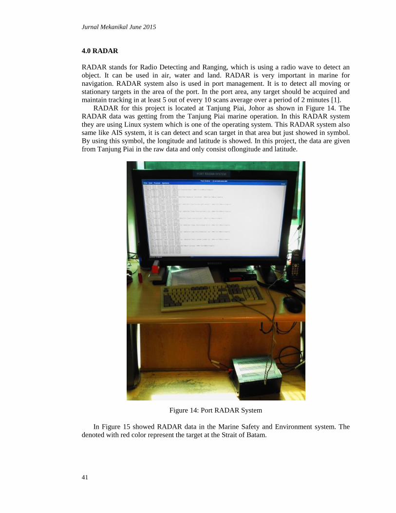
Figure 14: Port RADAR System
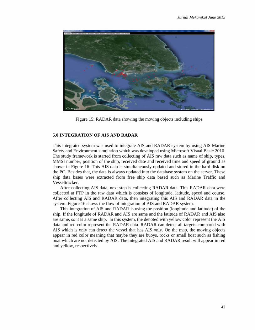
In Figure 15 showed RADAR data in the Marine Safety and Environment system. The
denoted with red color represent the target at the Strait of Batam.
Jurnal Mekanikal June 2015
42
Figure 15: RADAR data showing the moving objects including ships
5.0 INTEGRATION OF AIS AND RADAR
This integrated system was used to integrate AIS and RADAR system by using AIS Marine
Safety and Environment simulation which was developed using Microsoft Visual Basic 2010.
The study framework is started from collecting of AIS raw data such as name of ship, types,
MMSI number, position of the ship, received date and received time and speed of ground as
shown in Figure 16. This AIS data is simultaneously updated and stored in the hard disk on
the PC. Besides that, the data is always updated into the database system on the server. These
ship data bases were extracted from free ship data based such as Marine Traffic and
Vesseltracker.
After collecting AIS data, next step is collecting RADAR data. This RADAR data were
collected at PTP in the raw data which is consists of longitude, latitude, speed and course.
After collecting AIS and RADAR data, then integrating this AIS and RADAR data in the
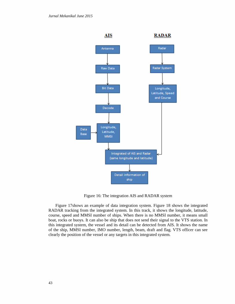
system. Figure 16 shows the flow of integration of AIS and RADAR system.
This integration of AIS and RADAR is using the position (longitude and latitude) of the
ship. If the longitude of RADAR and AIS are same and the latitude of RADAR and AIS also
are same, so it is a same ship. In this system, the denoted with yellow color represent the AIS
data and red color represent the RADAR data. RADAR can detect all targets compared with
AIS which is only can detect the vessel that has AIS only. On the map, the moving objects
appear in red color meaning that maybe they are buoys, rocks or small boat such as fishing
boat which are not detected by AIS. The integrated AIS and RADAR result will appear in red
and yellow, respectively.
Jurnal Mekanikal June 2015
43
Figure 16: The integration AIS and RADAR system
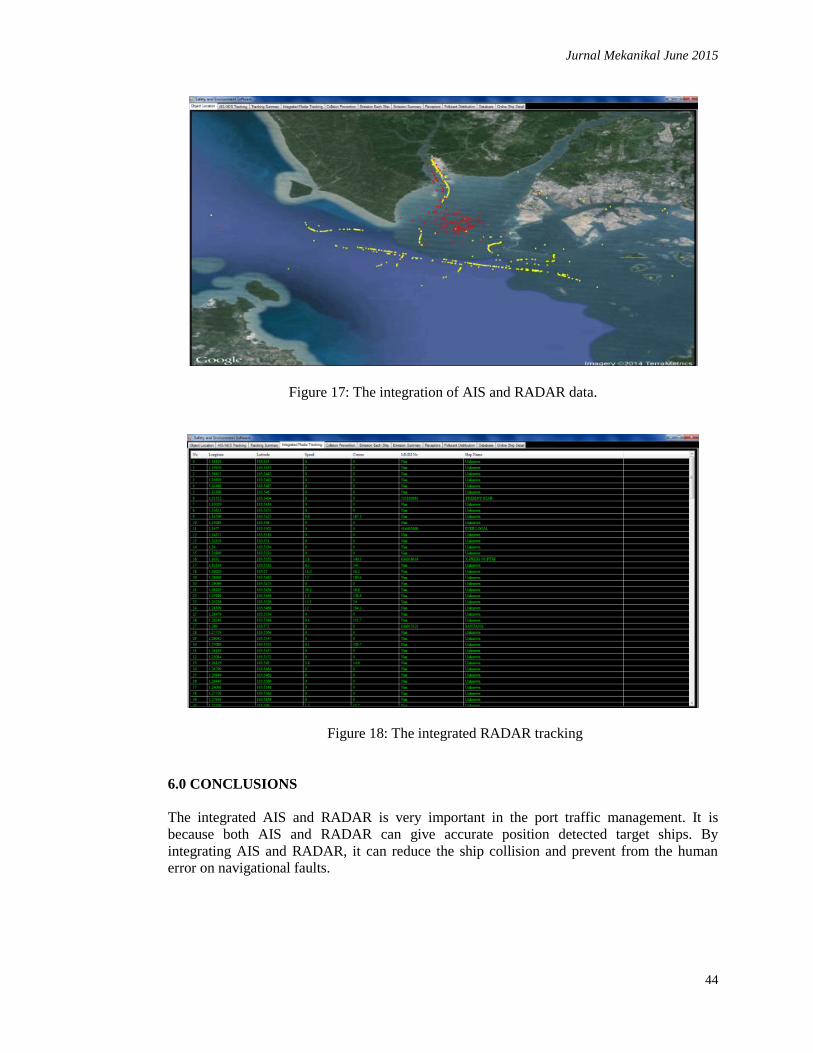
Figure 17shows an example of data integration system. Figure 18 shows the integrated
RADAR tracking from the integrated system. In this track, it shows the longitude, latitude,
course, speed and MMSI number of ships. When there is no MMSI number, it means small
boat, rocks or buoys. It can also be ship that does not send their signal to the VTS station. In
this integrated system, the vessel and its detail can be detected from AIS. It shows the name
of the ship, MMSI number, IMO number, length, beam, draft and flag. VTS officer can see
clearly the position of the vessel or any targets in this integrated system.
Jurnal Mekanikal June 2015
44
Figure 17: The integration of AIS and RADAR data.
Figure 18: The integrated RADAR tracking
6.0 CONCLUSIONS
The integrated AIS and RADAR is very important in the port traffic management. It is
because both AIS and RADAR can give accurate position detected target ships. By
integrating AIS and RADAR, it can reduce the ship collision and prevent from the human
error on navigational faults.
Jurnal Mekanikal June 2015
45
ACKNOWLEDGEMENTS
The authors would like to gratefully acknowledge Faculty of Mechanical Engineering,
Universiti Teknologi Malaysia, and International Society of Ocean, Mechanical and
Aerospace -scientists and engineers-, SMP Negeri 2 Batam in Belakang Padang, Indonesia,
Politeknik Negeri Batam, PTP and friends for giving full support.
REFERENCES
1. Bin Lin, Chih Hao Huang, 2006. Comparison Between ARPA RADAR and AIS
Characteristic for Vessle Traffic Services. Journal of marine science and technology, 14
(3), pp. 182-289.
2. Pelabuhan Tanjung Pelepas, 2009. Pelabuhan Tanjung Pelepas Sdn Bhd. [Online]
Available athttp://www.ptp.com.my/strategic.html
3. International Society of Ocean, Mechanical and Aerospace, 2014,
http://isomase.org/SERC.php
4. Chan Su Yang, T. H. Kim, D. Hong, H. W. Ahn., 2013. Design of integrated ship
monitoring system using SAR, RADAR and AIS. Ocean Sensing and Monitoring,
Volume 8724.
5. IMO, 1998. Recommendation on performance standard for a universal shipborne
Automatic Identification System (AIS), London: IMO Resolution MSC 74 (69).
6. IMO, 2002. Guidelines for the onboard operational use of shipbord Automatic
Identication System (AIS).
7. J.Koto, M.Rashidi and A.Maimun, 2014. Tracking of ship navigation in the Strait of
Malacca using automatic identification system. Development in maritime transportation
and exploitation of sea resources.
8. Kevin, G., 2007. Latest technological developments in vessel trcaking and monitoring.
Port technology international, pp. 50-52.
9. Maciej, 2010. Low cost AIS receiver for coastal zone monitoring, Poland: s.n.
10. Sudhir Kumar, Jung Hwan Song, Kazuo Ouchi, 2008. Preliminary technique to integrate
SAR and AIS for ship detection and identification.