integration of msc.adams virtual prototyping technology ...€¦ · namely adams/controls,...
TRANSCRIPT

Integration of MSC.ADAMS Virtual Prototyping Technology into Westland Helicopters CAD/CAE Architecture David Ellis, John Tedbury, Chris Fendt Mathematical Modelling Westland Helicopters , Yeovil, Somerset, UK Abstract Westland Helicopters have conducted an extensive evaluation of the MSC.ADAMS (hereafter referred to as ADAMS) suite of virtual prototyping software tools within the Mathematical Modelling department. The primary objective of the evaluation was to identify a range of applications which are currently catered for by “in-house” bespoke codes and establish solutions based on the ADAMS product range. To date the effort has concentrated on terrain interface load evaluations and has resulted in the development of landing gear sub-system models and ship deck restraint system models. In addition to identifying where ADAMS-based solutions can supersede “in-house” methods and deliver higher fidelity results, the evaluation aims to highlight the potential impact on current Math Modelling processes based on the interoperability of the ADAMS core products and appropriate extension products, namely ADAMS/Controls, ADAMS/Flex, ADAMS/Autoflex and CAT/ADAMS. Introduction In an effort to define an integrated/interoperable CAD-CAE architecture for Westland Helicopters Engineering Directorate, the Math Modelling department conducted a thorough evaluation of the ADAMS core products (ADAMS/View, ADAMS/Solver, ADAMS/PPT) and the appropriate extension products (ADAMS/Flex, ADAMS/Autoflex, ADAMS/Controls). The evaluation also considered interfacing ADAMS products with the Westland Helicopter CAD environment via CAT/ADAMS. The predominant role of the Math Modelling department is the generation of externally loaded and ballasted full airframe finite element models for subsequent structural analyses with MSC.Nastran. The results from the FE analyses (internal structural load distributions) are utilised by the Stress Engineering function within Westland Helicopters to substantiate the airframe for static strength. Airframe dynamic analyses are also conducted using MSC.Nastran to develop coupled rotor-fuselage systems with low levels of dynamic response. The Math Modelling department are also responsible for the generation of all external loads other than flight-induced aerodynamic loads. Non-flight induced external loads applied to the airframe finite element representation include loads induced during landing, taxiing (on smooth and rough ground), taxiing over bumps and steps (deck cleats), ship deck handling, jacking and restraint (often referred to as lashing). Various “in-house” methods have been developed to derive these external loads. Current methods are based on “in-house” FORTRAN code development, Matlab/Simulink-based solutions, MathCad-based solutions and various spreadsheet applications. The first part of this paper briefly outlines examples where ADAMS-based solutions have been developed to replace the “in-house” methods and illustrates how the ADAMS-based solution provides a more versatile, flexible and expansible approach. The second part of this paper illustrates how the ADAMS suite of virtual prototyping software integrates with the existing Westland CAD/CAE architecture and illustrates
how the software can enable process improvement both within Math Modelling and across engineering functional attribute boundaries. 1.1 Landing Loads There is only one way to be certain of the actual performance of a new landing gear design and that is by conducting physical drop tests. However the landing loads applied to the rotorcraft airframe have to be defined as early as possible within the airframe design cycle. The accurate prediction of the landing gear performance at this early stage of the design process is most advantageous as it significantly reduces risk. Testing is expensive, as it requires both considerable manpower and time, especially if component re -design and further testing is required to bring the performance of the landing gear within specification. The use of mathematical modelling for predicting landing gear performance has the following advantages: - • Confirms the performance that can be achieved over a wide range of operating
conditions (what-if type studies) • Provides the design community more accurate data with which to work, by
determining some of the more salient landing gear characteristics early in the process
• Considerable testing time, and thus cost, can be saved by reducing the amount
of further work required to optimise the landing gear performance • A “verified mathematical model” can be used to calculate the landing gear
performance for other landing conditions, or even replace some of the testing Because of these advantages, the Math Modelling departmental methods for predicting landing gear performance are continually being reviewed and improved. Over the years the modelling method for landing loads at Westland Helicopters has changed from FORTRAN, to Matlab/Simulink, then to MSC.ADAMS. Each change has primarily been triggered by the inability of the existing method to readily accommodate enhancement. The first step in moving to a new method is to evaluate it against the proven existing method. The first evaluation was conducted using a single leg drop test where both test data and simulation data had been correlated. The ADAMS landing gear model is illustrated in figure 1 below: -

Figure 1 - ADAMS Landing Gear Model Figure 2 below compares the discrepancy in the maximum force induced at the ground contact between the existing method, the ADAMS method and physical test data. Generally the ADAMS model produced results closer to the test data than the existing simulation method [1 ]: -
Ground Force Comparison
-10%
-5%
0%
5%
10%
15%
M1-1 M1-2 M2-1 M2-2 M3-1 M3-1R
M3-2 M4-1 M4-2 M4-3 ML10-4
ML4-4
ML9-4A
ML9-5
Drop No
Error
MATLAB/SIMULINK ADAMS
Figure 2 – Comparison of Results
The second evaluation was pitched at an application where good correlation between the existing simulation method and test data had not been established. The generally held belief was that the existing model did not include a critical degree-of-freedom to fully capture the drop test dynamics. Including this degree-of-freedom in the ADAMS model (with relative ease) yielded good results as illustrated in figure 3: -

-0.5 0 0.5 1 1.5 2 2.5 3 3.5 40
500
1000
1500
2000
2500
3000
3500
4000
4500
5000
oleo stroke (in)
groundforce(lbf)
drop test- level landing @ 10 f t /s
ExistingA D A M Sdrop test
-0.5 0 0.5 1 1.5 2 2.5 3 3.5 4-1000
0
1000
2000
3000
4000
5000
oleo stroke (in)
groundforce(lbf)
drop test - 14 degree tail down @ 10 ft/s
ExistingADAMSdrop test
Figure 3: Drop Test Results – Simulation versus Physical Test The figures above compare drop test data with results from the existing simulation model and results from the ADAMS model. Based on the success of developing single gear models, full aircraft drop test simulations have been developed and design-of-experiment methods have been applied directly in ADAMS to evaluate rotorcraft landing gear performance and ground clearance criteria for sloped landings [2]. The landing loads evaluation has successfully illustrated that models created using ADAMS can be used to accurately predict the performance of landing gear
designs and compute the corresponding landing gear loads, provided that these models include the correct amount of complexity necessary to represent the physical processes involved. The evaluation also highlighted the ease with which ADAMS models can be modified and/or enhanced. 1.2 Lashing Loads Lashings (strops) are used to secure rotorcraft on the ground and on ship decks during severe weather conditions. The lashing arrangement must be secure enough to prevent the aircraft from sliding or toppling. Current specifications require Lynx, EH101 and Apache rotorcraft to be lashed securely on a multitude of different ship decks with several lashing combinations coupled with a range of sea/wind conditions. The resulting loads in the lashings are then quantified to verify that they do not damage the rotorcraft by exceeding the structural integrity of the airframe at the lashing point or damage the strop. The current analysis is based on an “in-house” Fortran program, which calculates the lashing loads by performing a static force and moment balance between the aircraft mass and the static reactions of the undercarriage and the lashings. The method has considerable drawbacks in terms of the turn-around time to conduct exhaustive lashing scenario analyses. Furthermore, development of the “in-house” code to account for true dynamic ship motion, incorporate airframe flexibility effects and enable design-of-experiment capabilities cannot be justified. It was therefore decided to develop a lashing analysis solution within ADAMS [3]. Four lashing cases have been compared using both analysis methods to demonstrate the validity of the ADAMS solution. In these cases the storm ship motion specification was used to specify roll and pitch angles superimposed with lateral, vertical and fore/aft accelerations. The results are summarised in figure 4 below: -
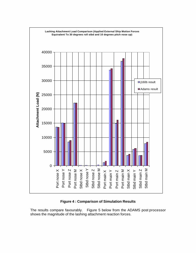
Figure 4 : Comparison of Simulation Results The results compare favourably. Figure 5 below from the ADAMS post processor shows the magnitude of the lashing attachment reaction forces.
Lashing Attachment Load Comparison (Applied External Ship Motion Forces Equivalent To 30 degrees roll stbd and 10 degrees pitch nose up)
0
5000
10000
15000
20000
25000
30000
35000
40000P
ort n
ose
X
Por
t nos
e Y
Por
t nos
e Z
Por
t nos
e M
Stb
d no
se X
Stb
d no
se Y
Stb
d no
se Z
Stb
d no
se M
Por
t mai
n X
Por
t mai
n Y
Por
t mai
n Z
Por
t mai
n M
Stb
d m
ain
X
Stb
d m
ain
Y
Stb
d m
ain
Z
Stb
d m
ain
M
Att
ach
men
t Lo
ad (N
)
j160b result
Adams result

Figure 5 : Lashing Loads in ADAMS/PPT
The corresponding variations of the external forces acting at the rotorcraft centre-of-gravity are shown in figure 6 below :-
Figure 6 : External Loads at Rotorcraft Centre-of-Gravity

The image below shows the actual ADAMS lashing model :-
Figure 7 : ADAMS Lashing Analysis Model
1.3 Ship Landing Loads For rotorcraft operating in a naval environment, there is a set of landing loads solely related to the rotorcraft landing on the ship’s deck. In the past, a complete rotorcraft Drop Test Vehicle (DTV) has been used to simulate these conditions (see figure 8). These tests are expensive to conduct and it can be difficult to ensure that some of the external forces, such as rotor lift, are correctly applied throughout the test. Also it is difficult to accurately measure the loads applied to each landing gear during the test.

Figure 8 : Drop Test Vehicle

The use of ADAMS models to compliment, and in some cases completely replace, this type of testing is being investigated [4]. An illustrative example of an ADAMS model of a rotorcraft that has been used to simulate this type of landing condition is shown in figure 9 below :-
Figure 9 : Ship Deck Landing Rotorcraft Model
The graph below (figure 10) shows the vertical force, as predicted by the ADAMS model, on each landing gear during a vertical landing onto a rolled deck.
0 0.05 0.1 0.15 0.2 0.25 0.3 0.35 0.4 0.45 0.5-5
0
5
10
15
20
25
30
35
40
45
Time (s)
Vertical Force (kN)
Landing with Rotorcraft Level and Rolled Deck
NLGMLGpMLGs
Figure 10 : Ship Deck Landing Loads

The use of an ADAMS model to simulate landing on a ship’s deck provides the following significant advantages : – • enables virtual testing of conditions that are not practicable to physically replicate
(e.g. moving ship’s deck) • the virtual test conditions can be taken to extremes that would be expected to
cause failure of some part of the rotorcraft • “what if” testing can be easily conducted 2.0 CAD-CAE Architecture Integration This section illustrates elements of the current CAD-CAE architecture at Westland Helicopters, indicates the improved interoperability provided by the ADAMS product range and discusses the consequent impact on current processes within the Math Modelling department. The company standard CAD platform is CATIA. Design and analysis harmonisation is realised by the accessibility of engineering CAD data (topology, material properties, mass and inertia properties, initial position and orientation) by the appropriate analysis environments (structural, thermal, multibody dynamics, control etc). Prior to the adoption of ADAMS, design data representing the airframe structure was only accessible by MSC.Patran via bespoke code referred to as ‘CatBatchXpress’. This was used predominantly to export CATIA FE representations of fabricated structures (typical of airframe construction) to MSC.Patran, although solid component models are also catered for. The complete airframe model is assembled in MSC.Patran and then mass ballasted. To complete the pre-processing for MSC.Nastran, the external loads discussed earlier are applied to the ballasted FE model (along with flight induced aerodynamic loads and main and tail rotor system loads). In terms of ground loads, the mass data used to ballast the FE model would also be used to develop the landing/ground induced loads externally to the above FE process. The introduction of ADAMS/Flex has provided a potential improvement in the current process. The ballasted FE model is used as the start point to deduce landing/ground loads. The undercarriage attachment points and lashing lugs are identified as attachment nodes for the FE Superelement analysis using an actual ballasted FE model which represents an airframe weight point (rolefit included). The modal neutral file is then used to build a flexible airframe part in ADAMS which can be integrated with rigid landing gear sub-system models. Complete or individual landing gear loads can then be simulated within the ADAMS environment accounting for the airframe flexibility if necessary. The same process applies to lashing load analyses. All the loads generated in ADAMS can be subsequently exported to the critical design load case selection process. Once the critical cases have been identified (based on airframe shear force and bending moment criteria) the corresponding load data can be exported directly from the ADAMS environment back to the FE model in readiness for the global analysis.

Other simulation environments at Westland Helicopters which benefit from the introduction of ADAMS core products and extension products are the computer aided control system design environments, namely Matlab/Simulink and MSC.EASY5. There is an initiative between Handling Qualities and Math Modelling to evaluate the ADAMS/Controls co-simulation capability with MSC.EASY5 and to develop initially a rigid blade main rotor model with the appropriate FORTRAN-based aerodynamic interfaces built into the ADAMS/Solver environment. The design community employ CATIA.Kinematics to a large extent to analyse space claim issues within mechanisms (tail rotor contro l system, main rotor control system, tail rotor driveshaft system, undercarriage system etc). The CAT/ADAMS extension offers an overall design process improvement by enabling the exchange of mechanism component CAD data into ADAMS for the subsequent addition of springs, bushings, loads and motion variables in order to perform a more realistic dynamic analysis. Using ADAMS/Autoflex, critical component flexibility can be easily integrated into the mechanism dynamic analysis to more accurately define load cases for subsequent structural analyses of individual components. Conclusions The evaluation and subsequent use of ADAMS core products and appropriate extension products has proved enormously successful within the Math Modelling department. ADAMS solutions for existing loads analyses have been successfully developed in considerably shorter time scales than previous methodologies allowed. In the majority of cases the ADAMS-based model produced better results when compared to test data. Furthermore, the ADAMS models are easily extensible compared to previous methods – the effects of a flexible airframe on landing loads and lashing loads can easily be accounted for by employing ADAMS/Flex during the model build process. In addition to offering an overall model development improvement, the adoption of ADAMS-based solutions has had an impact on the overall processes employed within Math Modelling, especially in terms of load generation and application to the FE airframe model for static substantiation. References 1. MSC.ADAMS Software Evaluation Interim Report
D G Ellis, J Tedbury, P Goodwin Math Modelling, Westland Helicopters, September 2001
2. Apache Sloped Landing Analysis
D G Ellis Math Modelling, Westland Helicopters, February 2002
3. Development of Lashing Analysis using MSC.ADAMS C E Fendt Math Modelling, Westland Helicopters, June 2002
4. Future Lynx – Review of Landing Loads
J Tedbury Math Modelling, Westland Helicopters, September 2002