integrated computational materials engineering approach to ... · pdf fileintegrated...
TRANSCRIPT

INTEGRATED COMPUTATIONAL MATERIALS ENGINEERING APPROACH TO DEVELOPMENT OF LIGHTWEIGHT
3GAHSS VEHICLE ASSEMBLY
Co-Principal Investigator: Dr. Louis G. Hector, Jr.Co-Principal Investigator: Dr. Jody Hall
United States Automotive Materials PartnershipJune 8, 2016 Project ID
LM080This presentation does not contain any proprietary, confidential, or otherwise restricted information
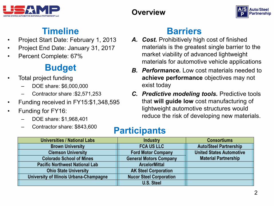
• Project Start Date: February 1, 2013• Project End Date: January 31, 2017• Percent Complete: 67%
A. Cost. Prohibitively high cost of finished materials is the greatest single barrier to the market viability of advanced lightweight materials for automotive vehicle applications
B. Performance. Low cost materials needed to achieve performance objectives may not exist today
C. Predictive modeling tools. Predictive tools that will guide low cost manufacturing of lightweight automotive structures would reduce the risk of developing new materials.
• Total project funding– DOE share: $6,000,000– Contractor share :$2,571,253
• Funding received in FY15:$1,348,595 • Funding for FY16:
– DOE share: $1,968,401– Contractor share: $843,600
Timeline
Budget
Barriers
Participants
Overview
Universities / National Labs Industry Consortiums Brown University FCA US LLC Auto/Steel Partnership
Clemson University Ford Motor Company United States Automotive Material Partnership Colorado School of Mines General Motors Company
Pacific Northwest National Lab ArcelorMittal Ohio State University AK Steel Corporation
University of Illinois Urbana-Champagne Nucor Steel Corporation U.S. Steel
2
Project Goal: • To reduce the lead time in developing and applying lightweight third generation advanced
high strength steel (3GAHSS) by integrating material models of different length scales into an Integrated Computational Materials Engineering (ICME) model
Project Objectives• Identify, validate (within 15% of experiments) and assemble length scale material models for
predicting 3GAHSS constitutive behavior for component forming and performance• Optimize assembly design using ICME-predicted 3GAHSS model to be 35% lighter and no
more than $3.18 cost per pound weight saved to meet DOE VTO gaps and targets¹.
October 2014 – September 2015 Objectives• Task 2 ‘Model Development’: Integrate QP980 material models and forming model to
produce an initial QP980 ICME Model. Produce new 3GAHSS (CMAT Med. Mn and CMAT Q&P) coupons for model development. Measure plastic flow and austenite transformation.
• Task 3 ‘Forming’: Room temperature stamping of QP980 T-Components to validate QP980 material, forming and ICME models.
• Task 4 ‘Assembly’: Assemble material models and forming model to produce an initial QP980 ICME Model.
• Task 5 ‘Design Optimization’: Substitute 3GAHSS into the side structure design; determine mass savings and performance impact
• Task 7 ‘Technical Cost Model’: Deferred to 2016 pending optimized 3GAHSS design. 1Light-Duty Vehicles Technical Requirements and Gaps for Lightweight and Propulsion Materials, Workshop, pp12, 2013, US DOE VTO
Relevance
3
Relevance
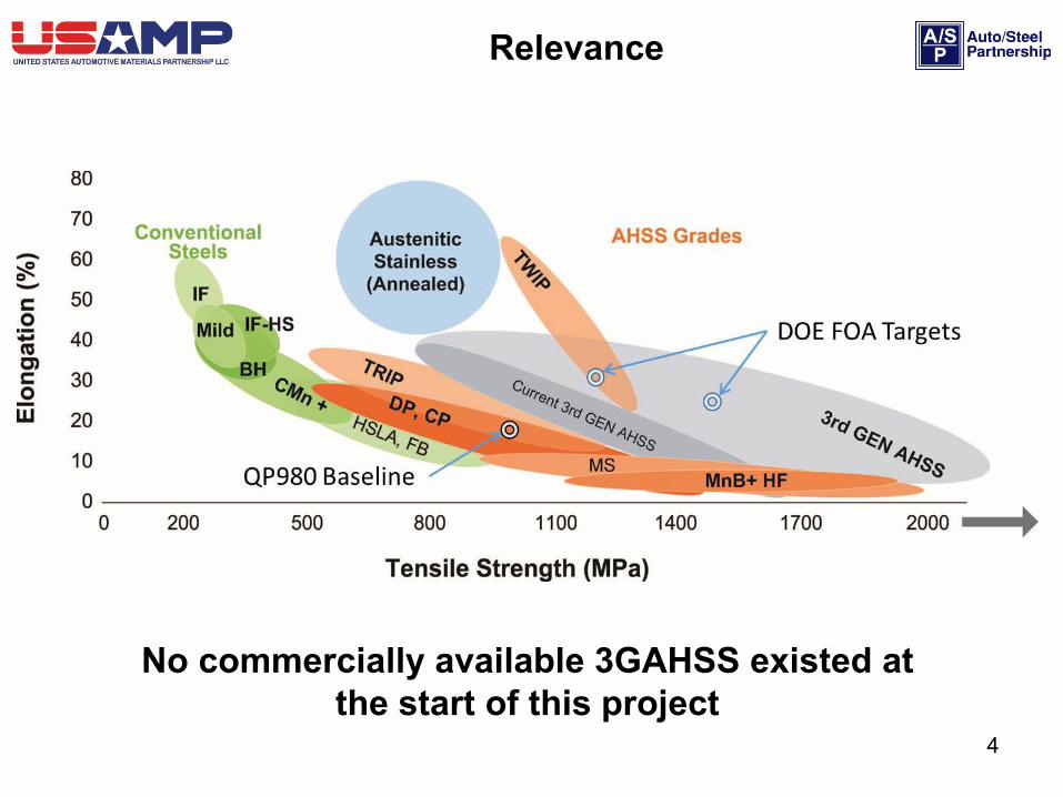
No commercially available 3GAHSS existed at the start of this project
4
Relevance
Predictive Modeling Tools• Primary deliverable: An ICME Model capable of predicting 3GAHSS flow behavior
and fracture to:– Reduce time and cost to develop and validate new 3GAHSS alloys– Improve manufacturability of the 3GAHSS automotive components with improved
forming simulations– Facilitate implementation of 3GAHSS alloys in automotive structures through improved
performance modeling– Estimate the cost of 3GAHSS components and assemblies
Cost Barrier: • Will demonstrate the ability to produce 3GAHSS materials at no more than $3.18
cost per pound weight saved.
Performance Barrier• Will demonstrate the viability of 3GAHSS steels to meet vehicle performance
requirements while reducing vehicle assembly weight (35% lighter)5
Approach/Strategy
• An ICME approach specifically aimed at 3GAHSS which will…– Further develop existing computational methodologies and tools – Enable the development of complete and consistent models both at the
component and assembly levels
• A highly collaborative partnership, under experienced USAMP consortium and A/SP leadership, has been created:
– OEM members: Responsible for system requirements, acceptance criteria and performance targets in the design of 3GAHSS components and automotive assemblies.
– A/SP steel companies: Responsible for design, manufacture and testing of new 3GAHSS alloys.
– Universities and national laboratory: Responsible for the development and validation of ICME material models.
6
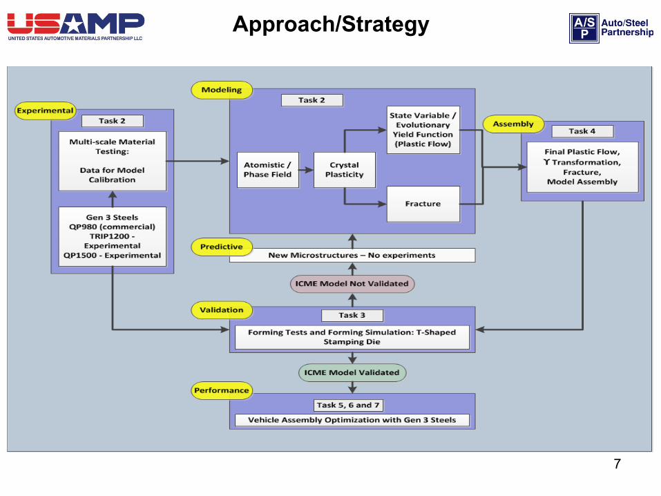
Approach/Strategy
7

Milestone Flow Chart(transition from baseline QP980 steel to New 3GAHSS steels)
8
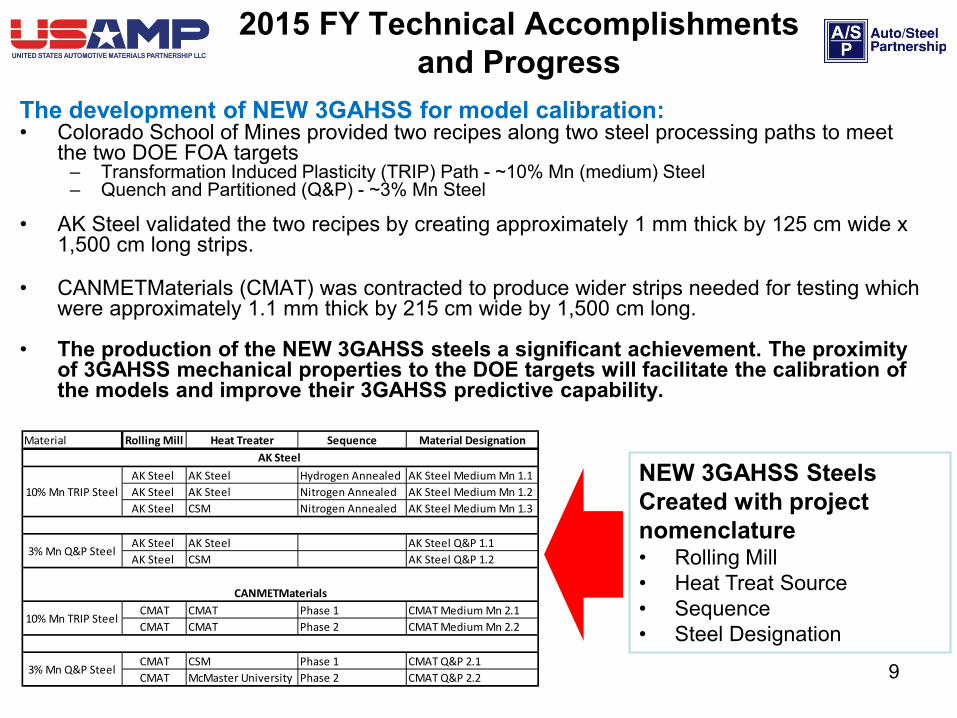
The development of NEW 3GAHSS for model calibration:• Colorado School of Mines provided two recipes along two steel processing paths to meet
the two DOE FOA targets– Transformation Induced Plasticity (TRIP) Path - ~10% Mn (medium) Steel – Quench and Partitioned (Q&P) - ~3% Mn Steel
• AK Steel validated the two recipes by creating approximately 1 mm thick by 125 cm wide x 1,500 cm long strips.
• CANMETMaterials (CMAT) was contracted to produce wider strips needed for testing which were approximately 1.1 mm thick by 215 cm wide by 1,500 cm long.
• The production of the NEW 3GAHSS steels a significant achievement. The proximity of 3GAHSS mechanical properties to the DOE targets will facilitate the calibration of the models and improve their 3GAHSS predictive capability.
2015 FY Technical Accomplishments and Progress
Material Rolling Mill Heat Treater Sequence Material Designation
AK Steel AK Steel Hydrogen Annealed AK Steel Medium Mn 1.1AK Steel AK Steel Nitrogen Annealed AK Steel Medium Mn 1.2AK Steel CSM Nitrogen Annealed AK Steel Medium Mn 1.3
AK Steel AK Steel AK Steel Q&P 1.1AK Steel CSM AK Steel Q&P 1.2
CMAT CMAT Phase 1 CMAT Medium Mn 2.1 CMAT CMAT Phase 2 CMAT Medium Mn 2.2
CMAT CSM Phase 1 CMAT Q&P 2.1CMAT McMaster University Phase 2 CMAT Q&P 2.2
AK Steel
10% Mn TRIP Steel
3% Mn Q&P Steel
10% Mn TRIP Steel
3% Mn Q&P Steel
CANMETMaterials
NEW 3GAHSS Steels Created with project nomenclature• Rolling Mill• Heat Treat Source• Sequence• Steel Designation
9
2015 FY Technical Accomplishments and Progress
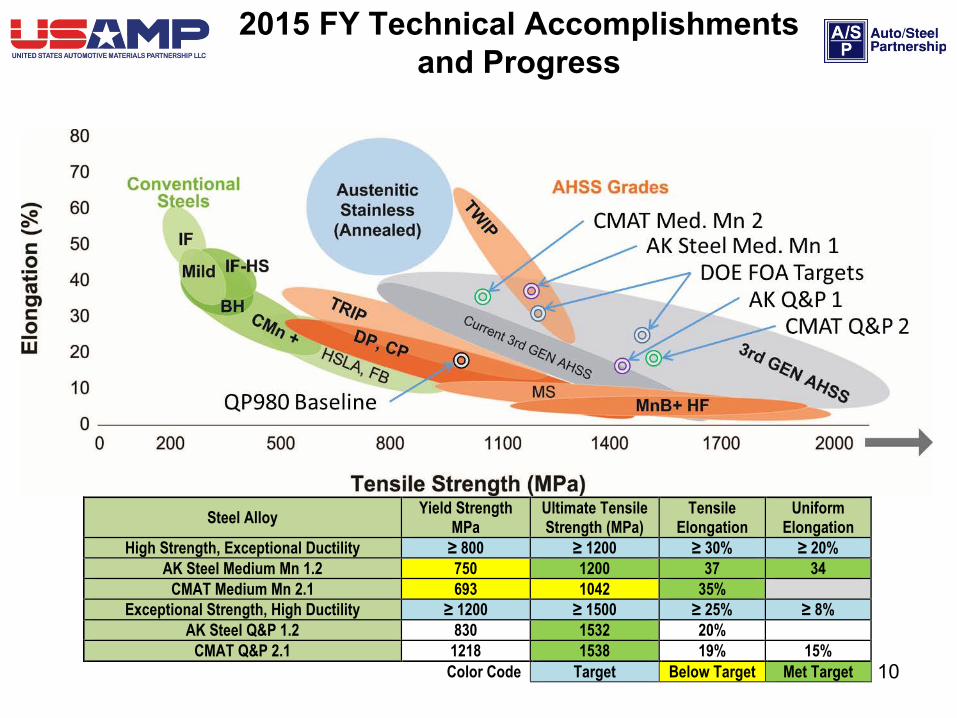
Steel Alloy Yield Strength MPa
Ultimate Tensile Strength (MPa)
Tensile Elongation
Uniform Elongation
High Strength, Exceptional Ductility ≥ 800 ≥ 1200 ≥ 30% ≥ 20% AK Steel Medium Mn 1.2 750 1200 37 34
CMAT Medium Mn 2.1 693 1042 35% Exceptional Strength, High Ductility ≥ 1200 ≥ 1500 ≥ 25% ≥ 8%
AK Steel Q&P 1.2 830 1532 20% CMAT Q&P 2.1 1218 1538 19% 15%
Color Code Target Below Target Met Target
10
Task 2: Material Model Development and Validation• Delivered Milestone #2: Meso-Scale Model on January 31, 2015.
– The assembled crystal plasticity model (CPM) and state variable model (SVM); computed flow curve for QP980 that was in agreement with experimental results.
• Developed a three dimensional (3D) representative volume element (RVE) for AK Steel Medium Mn 1.3 using DREAM 3D©
• Improved assembled QP980 material models:– Expanded models to include more crystals (polycrystalline)– Added shell finite element capability to better support design optimization
• Produced NEW 3GAHSS strips and started testing of excised coupons to develop constitutive data needed for model calibration
• Began fracture model development starting with QP980• Developed a new experimental procedure to measure retained austenite as
a function of strain using digital image correlation and Argonne National Laboratory’s (ANL) Synchrotron High Energy X-Ray Diffraction (HEXRD).
– Included transformation kinetics in the assembled QP980 material models
2015 FY Technical Accomplishments and Progress
11
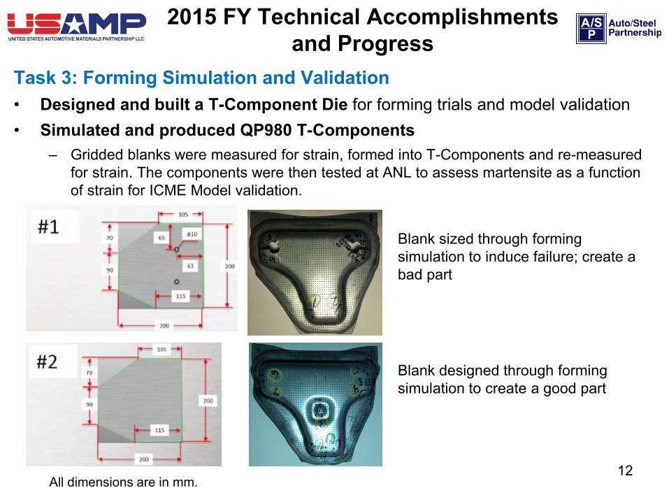
Task 3: Forming Simulation and Validation• Designed and built a T-Component Die for forming trials and model validation• Simulated and produced QP980 T-Components
– Gridded blanks were measured for strain, formed into T-Components and re-measured for strain. The components were then tested at ANL to assess martensite as a function of strain for ICME Model validation.
2015 FY Technical Accomplishments and Progress
Blank sized through forming simulation to induce failure; create a bad part
Blank designed through forming simulation to create a good part
All dimensions are in mm.12
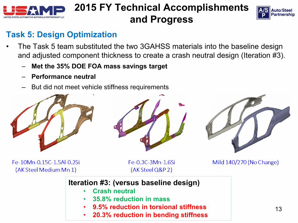
Task 5: Design Optimization• The Task 5 team substituted the two 3GAHSS materials into the baseline design
and adjusted component thickness to create a crash neutral design (Iteration #3).– Met the 35% DOE FOA mass savings target– Performance neutral– But did not meet vehicle stiffness requirements
2015 FY Technical Accomplishments and Progress
Iteration #3: (versus baseline design)• Crash neutral• 35.8% reduction in mass• 9.5% reduction in torsional stiffness• 20.3% reduction in bending stiffness
13
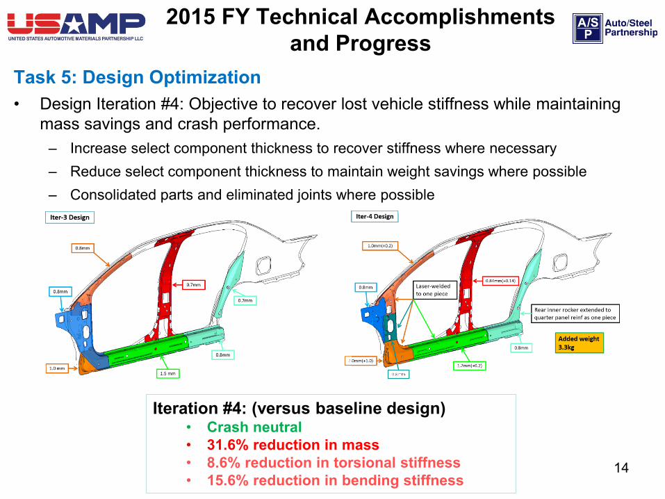
Task 5: Design Optimization• Design Iteration #4: Objective to recover lost vehicle stiffness while maintaining
mass savings and crash performance.– Increase select component thickness to recover stiffness where necessary– Reduce select component thickness to maintain weight savings where possible– Consolidated parts and eliminated joints where possible
2015 FY Technical Accomplishments and Progress
Iteration #4: (versus baseline design)• Crash neutral• 31.6% reduction in mass• 8.6% reduction in torsional stiffness• 15.6% reduction in bending stiffness
14

Task 4 / 6: Assembly and Integration• Created a framework linking the assembled CPM and SVM material models with
the forming model.• Signed CRADA with NIST to use the DSpace Data Repository for the storage
and retrieval of project data.• Developed a data ontology• Currently uploading project data
Task 7: Technical Cost Model• Baseline technical cost model was completed in 2014 FY. Task will resume once
an optimized 3GAHSS design has been completed.
2015 FY Technical Accomplishments and Progress
15
Response to Reviewers’ Comments
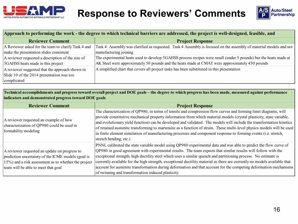
Reviewer Comment Project ResponseA Reviewer asked for the team to clarify Task 4 and make the presentation slides consistent
Task 4: Assembly was clarified as requested. Task 4 Assembly is focused on the assembly of material models and not manufacturing joining
A reviewer requested a description of the size of 3GAHSS heats made in this project
The experimental heats used to develop 3GAHSS process recipes were small (under 5 pounds) but the heats made at AK Steel were approximately 50 pounds and the heats made at CMAT were approximately 450 pounds
A reviewer suggested that the approach shown in Slide 10 of the 2014 presentation was too complicated
A simplified chart that covers all project tasks has been substituted in this presentation
Reviewer Comment Project Response
A reviewer requested an example of how characterization of QP980 could be used in formability modeling
The characterization of QP980, in terms of tensile and compression flow curves and forming limit diagrams, will provide constitutive mechanical property information from which material models (crystal plasticity, state variable, and evolutionary yield function) can be developed and validated. The models will include the transformation kinetics of retained austenite transforming to martensite as a function of strain. These multi-level physics models will be used in finite element simulation of manufacturing processes and component response to forming events (i.e. stretch, stretch bending, etc.)
A reviewer requested an update on progress to prediction uncertainty of the ICME models (goal is 15%) and a risk assessment as to whether the project team will be able to meet that goal
PNNL calibrated the state variable model using QP980 experimental data and was able to predict the flow curve of QP980 in good agreement with experimental results. The team expects that similar results will follow with the exceptional strength, high ductility steel which uses a similar quench and partitioning process. No estimate is currently available for the high strength, exceptional ductility material as there are currently no models available that account for austenite transformation during deformation and that account for the competing deformation mechanisms of twinning and transformation induced plasticity
Approach to performing the work - the degree to which technical barriers are addressed, the project is well-designed, feasible, and
Technical accomplishments and progress toward overall project and DOE goals – the degree to which progress has been made, measured against performance indicators and demonstrated progress toward DOE goals
16
Response to Reviewers’ Comments
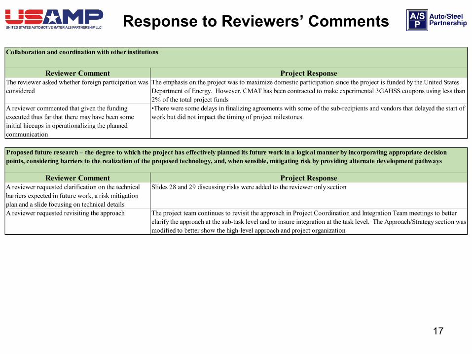
Reviewer Comment Project ResponseThe reviewer asked whether foreign participation was considered
The emphasis on the project was to maximize domestic participation since the project is funded by the United States Department of Energy. However, CMAT has been contracted to make experimental 3GAHSS coupons using less than 2% of the total project funds
A reviewer commented that given the funding executed thus far that there may have been some initial hiccups in operationalizing the planned communication
•There were some delays in finalizing agreements with some of the sub-recipients and vendors that delayed the start of work but did not impact the timing of project milestones.
Reviewer Comment Project ResponseA reviewer requested clarification on the technical barriers expected in future work, a risk mitigation plan and a slide focusing on technical details
Slides 28 and 29 discussing risks were added to the reviewer only section
A reviewer requested revisiting the approach The project team continues to revisit the approach in Project Coordination and Integration Team meetings to better clarify the approach at the sub-task level and to insure integration at the task level. The Approach/Strategy section was modified to better show the high-level approach and project organization
Collaboration and coordination with other institutions
Proposed future research – the degree to which the project has effectively planned its future work in a logical manner by incorporating appropriate decision points, considering barriers to the realization of the proposed technology, and, when sensible, mitigating risk by providing alternate development pathways
17
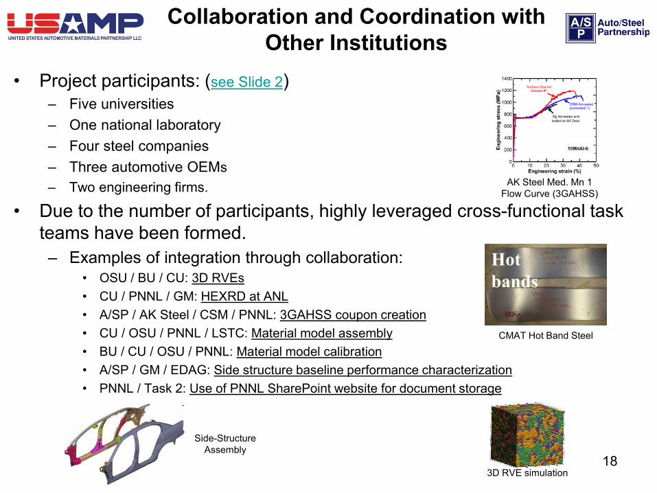
• Project participants: (see Slide 2) – Five universities– One national laboratory– Four steel companies– Three automotive OEMs – Two engineering firms.
• Due to the number of participants, highly leveraged cross-functional task teams have been formed. – Examples of integration through collaboration:
• OSU / BU / CU: 3D RVEs• CU / PNNL / GM: HEXRD at ANL• A/SP / AK Steel / CSM / PNNL: 3GAHSS coupon creation• CU / OSU / PNNL / LSTC: Material model assembly• BU / CU / OSU / PNNL: Material model calibration• A/SP / GM / EDAG: Side structure baseline performance characterization• PNNL / Task 2: Use of PNNL SharePoint website for document storage
Collaboration and Coordination with Other Institutions
Hot bands
3D RVE simulation
Side-Structure Assembly
CMAT Hot Band Steel
AK Steel Med. Mn 1 Flow Curve (3GAHSS)
18

1. To develop a annealing simulator process for the CMAT Q&P 2 Steel that produces similar properties achieved with the previously used salt bath process
2. To calibrate the 3GAHSS ICME Model for both 3GAHSS materials within 15% of experimental results
3. To integrate developing 3GAHSS fracture models into the 3GAHSS ICME Model
4. To recover stiffness in the 3GAHSS side-structure design while maintaining mass savings
Remaining Challenges and Barriers
19

Proposed Future Work
For the period October 2015 – September 2016• Task 2: Material Model Development and Validation
– Complete rolling and heat treatment of remaining 3GAHSS ingots at CMAT.– Complete testing of 3GAHSS materials at Clemson University and ANL– Complete the development and calibration of the 3GAHSS models (material, forming
and subsequent ICME model). – Complete fracture model calibration (QP980 and 3GAHSS) and integrate with the ICME
model.
• Task 3: Forming Model Development and Validation – Room temperature stamp T-Components from 3GAHSS materials– Validate material and forming models using QP980 and 3GAHSS T-Components
• Task 4: Model Assembly– Assemble material and forming models into an initial ICME Model for QP980 (baseline)
• Provide initial 3GAHSS predictions using assembled material models
– Refine assembled ICME material models with optimization loops using defined input/output parameters for each material length scale model
– Load all project data into the NIST DSpace Data Repository20
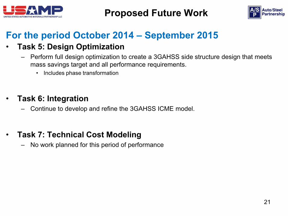
For the period October 2014 – September 2015• Task 5: Design Optimization
– Perform full design optimization to create a 3GAHSS side structure design that meets mass savings target and all performance requirements.• Includes phase transformation
• Task 6: Integration– Continue to develop and refine the 3GAHSS ICME model.
• Task 7: Technical Cost Modeling – No work planned for this period of performance
Proposed Future Work
21
Summary
• The first year (Feb. 2013 – Jan. 2014) focused mostly on developing baselines.– Material testing to develop the baseline constitutive material property information – Model development to adapt existing material models for AHSS – Identification and characterization of the baseline side-structure assembly
• The second year (Feb. 2014 – Jan. 2015) began calibrating models to the baseline QP980 steel and producing 3GAHSS materials
– Assembled and calibrated the material models using the baseline QP980 steel data.– Identified a T-Component die for validating material and forming models– Produced two 3GAHSS materials for model calibration– Characterized the performance of the baseline side-structure assembly against defined load cases
• The third year (Feb. 2015 – Jan. 2016) began integrating models, testing of 3GAHSS and generating 3GAHSS side structure designs
– Produced additional 3GAHSS and began testing to develop constitutive material property information.– Built a T-Component die to validate material and forming models.– Integrated material and forming models and aligned integrated models with design optimization. – Generated 3GAHSS side structure designs to meet DOE FOA targets– Began fracture model development
• The fourth year (Feb. 2016 – Jan. 2017) will focus on remaining milestones and final project deliverables; the ICME Model and Data Model. 22
Two NEW 3GAHSS materials now exist!
A preliminary 3GAHSS ICME Model exists!
A 3GAHSS Data Model has been created!
High Level Summary
23
This material is based upon work supported by the Department of Energy NationalEnergy Technology Laboratory under Award Number No. DE-EE0005976.
This report was prepared as an account of work sponsored by an agency of theUnited States Government. Neither the United States Government nor any agencythereof, nor any of their employees, makes any warranty, express or implied, orassumes any legal liability or responsibility for the accuracy, completeness, orusefulness of any information, apparatus, product, or process disclosed, orrepresents that its use would not infringe privately owned rights. Reference hereinto any specific commercial product, process, or service by trade name, trademark,manufacturer, or otherwise does not necessarily constitute or imply itsendorsement, recommendation, or favoring by the United States Government or anyagency thereof. The views and opinions of authors expressed herein do notnecessarily state or reflect those of the United States Government or any agencythereof. Such support does not constitute an endorsement by the Department ofEnergy of the work or the views expressed herein.
Acknowledgement

Back-up Slides
25
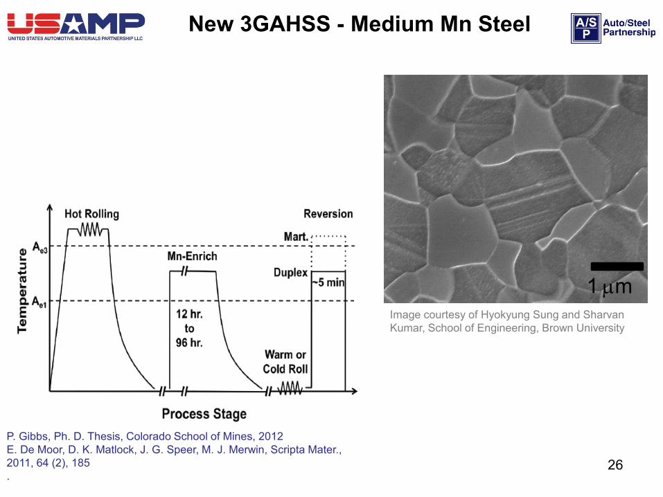
New 3GAHSS - Medium Mn Steel
1 µm
P. Gibbs, Ph. D. Thesis, Colorado School of Mines, 2012E. De Moor, D. K. Matlock, J. G. Speer, M. J. Merwin, Scripta Mater., 2011, 64 (2), 185.
Image courtesy of Hyokyung Sung and Sharvan Kumar, School of Engineering, Brown University
26

New 3GAHSS – Q&P Steel
G. Thomas, J. Speer, D. Matlock, J. Michael," Microscopy and Microanalysis, vol. 17, pp. 368-373, 2011.
27
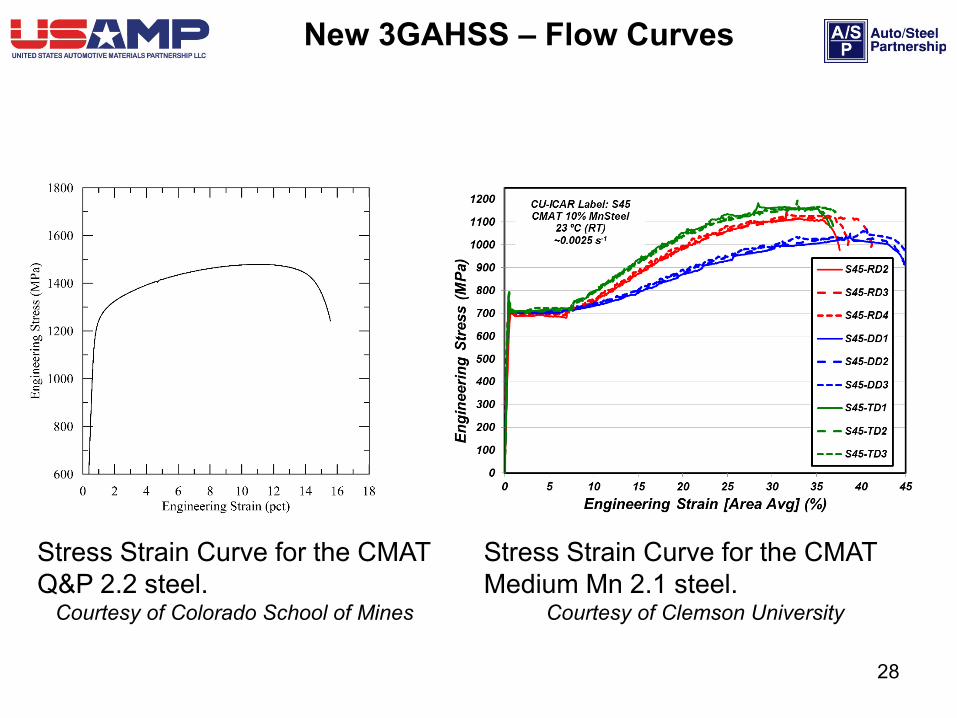
Stress Strain Curve for the CMAT Medium Mn 2.1 steel.
Courtesy of Clemson University
Stress Strain Curve for the CMAT Q&P 2.2 steel.
Courtesy of Colorado School of Mines
New 3GAHSS – Flow Curves
28
Engineering strain
0.0 0.1 0.2 0.3 0.4 0.5
Eng
inee
ring
stre
ss (M
Pa)
0
500
1000
1500
2000
Exp. #1Exp. #2Exp. #3Sim. (wothout phase transformation)Sim. (with phase transformation)
Engineering strain 11
0.0 0.1 0.2 0.3 0.4 0.5
Eng
inee
ring
stre
ss 1
1 (M
Pa)
0
200
400
600
800
1000
1200
1400
Exp. #1 Exp. #2Exp. #3
Crystal Plasticity Calibration
0
100
200
300
400
500
600
700
800
900
1000
1100
1200
0 5 10 15 20 25 30 35 40 45
Engi
neer
ing
Stre
ss (M
Pa)
Engineering Strain [A1] (%)
S45-RD2
S45-RD3
S45-RD4
S45-DD1
S45-DD2
S45-DD3
S45-TD1
S45-TD2
S45-TD3
CMAT 10% MnSteelCU-ICAR Label: S45
23 ºC (RT)~0.0025 s-1
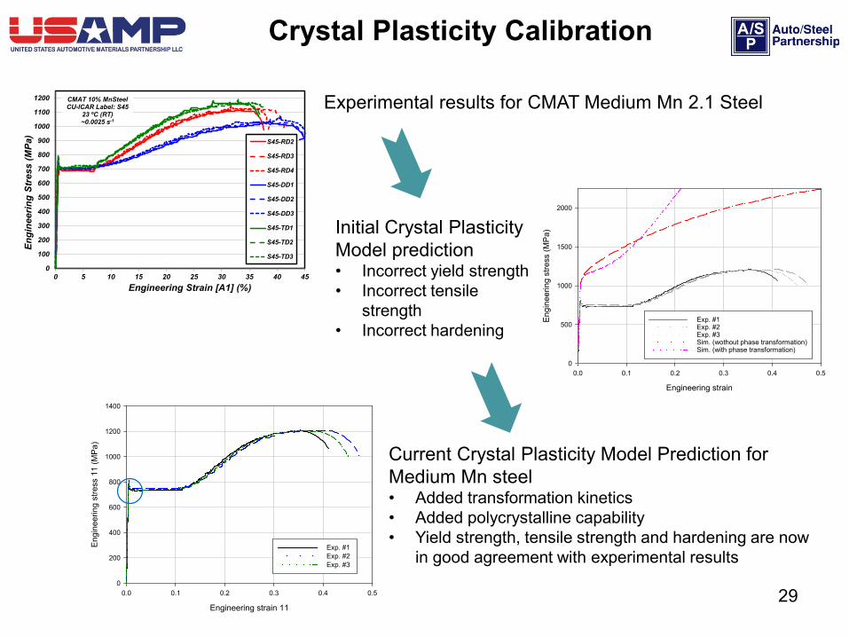
Experimental results for CMAT Medium Mn 2.1 Steel
Initial Crystal Plasticity Model prediction• Incorrect yield strength• Incorrect tensile
strength• Incorrect hardening
Current Crystal Plasticity Model Prediction for Medium Mn steel• Added transformation kinetics• Added polycrystalline capability• Yield strength, tensile strength and hardening are now
in good agreement with experimental results
29
30
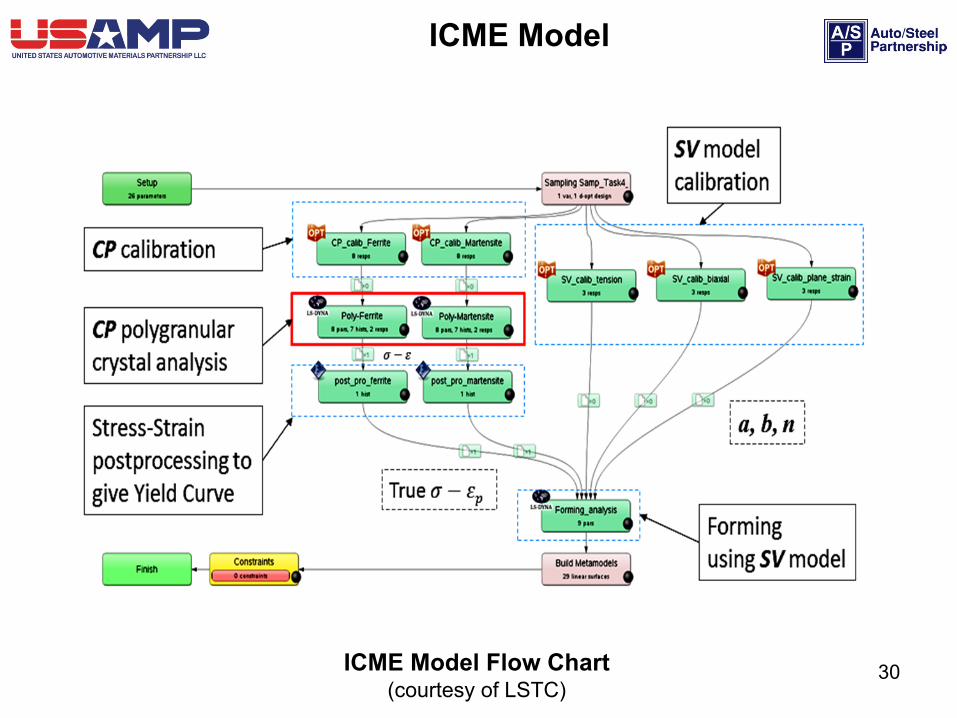
ICME Model
ICME Model Flow Chart (courtesy of LSTC)