integral volume booster installation instructions - lesman · sipart ps2 smart valve positioner...
TRANSCRIPT
11/2014Edition
Answers for industry.
Installation Instructions
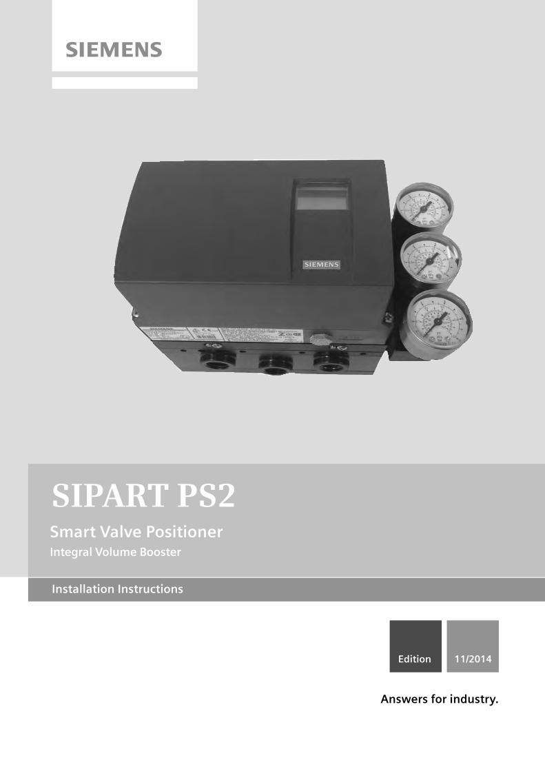
Smart Valve PositionerIntegral Volume Booster
SIPART PS2

SIPART PS2
Smart Valve Positioner Integral Volume Booster Installation Instructions
Hardware Installation Manual
11/2014 A5E35229820-AA
Introduction 1
Safety notes 2
Theory of Operation 3
Installing/mounting 4
Service and maintenance 5
Dimension drawings 6
Siemens AG Industry Sector Postfach 48 48 90026 NÜRNBERG GERMANY
Order number: A5E35229820 Ⓟ 11/2014 Subject to change
Copyright © Siemens AG 2014. All rights reserved
Legal information Warning notice system
This manual contains notices you have to observe in order to ensure your personal safety, as well as to prevent damage to property. The notices referring to your personal safety are highlighted in the manual by a safety alert symbol, notices referring only to property damage have no safety alert symbol. These notices shown below are graded according to the degree of danger.
DANGER indicates that death or severe personal injury will result if proper precautions are not taken.
WARNING indicates that death or severe personal injury may result if proper precautions are not taken.
CAUTION indicates that minor personal injury can result if proper precautions are not taken.
NOTICE indicates that property damage can result if proper precautions are not taken.
If more than one degree of danger is present, the warning notice representing the highest degree of danger will be used. A notice warning of injury to persons with a safety alert symbol may also include a warning relating to property damage.
Qualified Personnel The product/system described in this documentation may be operated only by personnel qualified for the specific task in accordance with the relevant documentation, in particular its warning notices and safety instructions. Qualified personnel are those who, based on their training and experience, are capable of identifying risks and avoiding potential hazards when working with these products/systems.
Proper use of Siemens products Note the following:
WARNING Siemens products may only be used for the applications described in the catalog and in the relevant technical documentation. If products and components from other manufacturers are used, these must be recommended or approved by Siemens. Proper transport, storage, installation, assembly, commissioning, operation and maintenance are required to ensure that the products operate safely and without any problems. The permissible ambient conditions must be complied with. The information in the relevant documentation must be observed.
Trademarks All names identified by ® are registered trademarks of Siemens AG. The remaining trademarks in this publication may be trademarks whose use by third parties for their own purposes could violate the rights of the owner.
Disclaimer of Liability We have reviewed the contents of this publication to ensure consistency with the hardware and software described. Since variance cannot be precluded entirely, we cannot guarantee full consistency. However, the information in this publication is reviewed regularly and any necessary corrections are included in subsequent editions.
Integral Volume Booster Installation Instructions Hardware Installation Manual, 11/2014, A5E35229820-AA 3
Table of contents
1 Introduction ............................................................................................................................................. 5
1.1 Purpose of this documentation ................................................................................................. 5
1.2 History ....................................................................................................................................... 5
1.3 Purpose ..................................................................................................................................... 5
1.4 Checking the consignment ....................................................................................................... 6
1.5 Transportation and storage ....................................................................................................... 6
1.6 Notes on Warranty .................................................................................................................... 7
2 Safety notes ............................................................................................................................................ 9
2.1 Warning Symbols ...................................................................................................................... 9
2.2 Laws and directives ................................................................................................................ 10
2.3 Conformity with European directives ...................................................................................... 10
2.4 Loss of safety of device with type of protection "Intrinsic safety Ex i" .................................... 11
3 Theory of Operation .............................................................................................................................. 13
4 Installing/mounting ................................................................................................................................ 15
4.1 Basic Safety Instructions ........................................................................................................ 15 4.1.1 Unsuitable Compressed Air .................................................................................................... 16 4.1.2 Prior to working on the control valve ....................................................................................... 17 4.1.3 Proper Mounting ..................................................................................................................... 17
4.2 Integral Volume Booster ......................................................................................................... 18
4.3 Installation ............................................................................................................................... 20
4.4 Pneumatic Connections .......................................................................................................... 31
4.5 Device Setup ........................................................................................................................... 32
5 Service and maintenance ...................................................................................................................... 35
5.1 Maintenance ........................................................................................................................... 35
6 Dimension drawings .............................................................................................................................. 39
6.1 Installation and Outline Drawings ........................................................................................... 39
Index..................................................................................................................................................... 41
Tables
Table 4- 1 Climate Class ............................................................................................................................... 18 Table 4- 2 Weight .......................................................................................................................................... 18
Table of contents
Integral Volume Booster Installation Instructions 4 Hardware Installation Manual, 11/2014, A5E35229820-AA
Figures
Figure 3-1 Single Acting Booster ................................................................................................................... 14
Integral Volume Booster Installation Instructions Hardware Installation Manual, 11/2014, A5E35229820-AA 5
Introduction 1 1.1 Purpose of this documentation
These instructions are a brief summary of important features, functions and safety information, and contain all information required for safe use of the device. Read the instructions carefully prior to installation and commissioning. In order to use the device correctly, first review its principle of operation.
The instructions are aimed at persons who mechanically assemble the device, connect it electrically, and start it up.
To achieve optimum usage of the device, read the detailed version of the instructions.
See also Process instrumentation catalog (http://www.siemens.com/processinstrumentation/catalogs)
Product information on SIPART PS2 in the Internet (http://www.siemens.com/sipartps2)
1.2 History The contents of these instructions are regularly reviewed and corrections are included in subsequent editions. We welcome suggestions for improvement.
The following table shows the most important changes in the documentation compared to each previous edition. Edition Remarks 11/2014 First edition of Installation Instructions for the SIPART PS2 Integral Volume Booster..
1.3 Purpose The electropneumatic positioner is used for the continuous control of process valves with pneumatic drives in the following industries.
● Chemicals
● Oil and gas
● Energy production
● Food and beverages
● Pulp and paper
● Water/waste water
● Pharmaceutical industry
● Offshore plants
Introduction 1.4 Checking the consignment
Integral Volume Booster Installation Instructions 6 Hardware Installation Manual, 11/2014, A5E35229820-AA
1.4 Checking the consignment 1. Check the packaging and the delivered items for visible damage.
2. Report any claims for damages immediately to the shipping company.
3. Retain damaged parts for clarification.
4. Check the scope of delivery by comparing your order to the shipping documents for correctness and completeness.
WARNING
Using a damaged or incomplete device
Danger of explosion in hazardous areas. • Do not use damaged or incomplete devices.
1.5 Transportation and storage To guarantee sufficient protection during transport and storage, observe the following:
● Keep the original packaging for subsequent transportation.
● Devices/replacement parts should be returned in their original packaging.
● If the original packaging is no longer available, ensure that all shipments are properly packaged to provide sufficient protection during transport. Siemens cannot assume liability for any costs associated with transportation damages.
CAUTION
Insufficient protection during storage
The packaging only provides limited protection against moisture and infiltration. • Provide additional packaging as necessary.
Introduction 1.6 Notes on Warranty
Integral Volume Booster Installation Instructions Hardware Installation Manual, 11/2014, A5E35229820-AA 7
1.6 Notes on Warranty The sales contract contains the entire obligation of Siemens. The warranty contained in the contract between the parties is the sole warranty of Siemens. Any statements continued herein do not create new warranties or modify the existing warranty.
For warranty and non-warranty service, refer to Customer/Product Support in this publication. All product designations may be trademarks or product names of Siemens Industry, Inc. or other supplier companies whose use by third parties for their own purposes could violate the rights of the owners.
Siemens Industry, Inc. assumes no liability for errors or omissions in this document or for the application and use of information in this document. The information herein is subject to change without notice.
Procedures in this document have been reviewed for compliance with applicable approval agency requirements and are considered sound practice. Neither Siemens Industry, Inc. nor these agencies are responsible for product uses not included in the approval certification(s) or for repairs or modifications made by the user.
Introduction 1.6 Notes on Warranty
Integral Volume Booster Installation Instructions 8 Hardware Installation Manual, 11/2014, A5E35229820-AA
Integral Volume Booster Installation Instructions Hardware Installation Manual, 11/2014, A5E35229820-AA 9
Safety notes 2
This device left the factory in good working condition. In order to maintain this status and to ensure safe operation of the device, observe these instructions and all the specifications relevant to safety.
Observe the information and symbols on the device. Do not remove any information or symbols from the device. Always keep the information and symbols in a completely legible state.
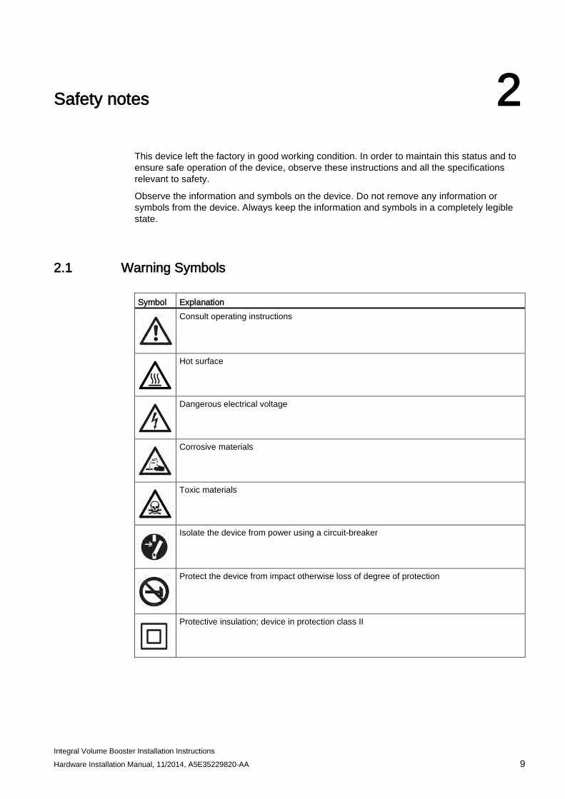
2.1 Warning Symbols Symbol Explanation
Consult operating instructions
Hot surface
Dangerous electrical voltage
Corrosive materials
Toxic materials
Isolate the device from power using a circuit-breaker
Protect the device from impact otherwise loss of degree of protection
Protective insulation; device in protection class II
Safety notes 2.2 Laws and directives
Integral Volume Booster Installation Instructions 10 Hardware Installation Manual, 11/2014, A5E35229820-AA
2.2 Laws and directives Observe the test certification, provisions and laws applicable in your country during connection, assembly and operation. These include, for example:
● National Electrical Code (NEC - NFPA 70) (USA)
● Canadian Electrical Code (CEC) (Canada)
Further provisions for hazardous area applications are for example:
● IEC 60079-14 (international)
● EN 60079-14 (EC)
2.3 Conformity with European directives The CE marking on the device shows conformity with the regulations of the following European guidelines: Electromagnetic Compatibil-ity EMC 2004/108/EC
Directive of the European Parliament and of the Council on the approximation of the laws of the Member States relating to elec-tromagnetic compatibility and repealing Directive 89/336/EEC.
Atmosphère explosible ATEX 94/9/EC
Directive of the European Parliament and the Council on the approximation of the laws of the Member States concerning equipment and protective systems intended for use in potential-ly explosive atmospheres.
LVD 2006/95/EC Directive of the European Parliament and of the Council of the harmonisation of the laws of Member States relating to electri-cal equipment designed for use within certain voltage limits.
The applied standards can be found in the EC conformity declaration of the device.
WARNING
Improper device modifications
Danger to personnel, system and environment can result from modifications to the device, particularly in hazardous areas. • Only carry out modifications that are described in the instructions for the device. Failure
to observe this requirement cancels the manufacturer's warranty and the product approvals.
Qualified personnel for hazardous area applications
Persons who install, connect, commission, operate, and service the device in a hazardous area must have the following specific qualifications:
● They are authorized, trained or instructed in operating and maintaining devices and systems according to the safety regulations for electrical circuits, high pressures, aggressive, and hazardous media.
● They are authorized, trained, or instructed in carrying out work on electrical circuits for hazardous systems.
● They are trained or instructed in maintenance and use of appropriate safety equipment according to the pertinent safety regulations.
Safety notes 2.4 Loss of safety of device with type of protection "Intrinsic safety Ex i"
Integral Volume Booster Installation Instructions Hardware Installation Manual, 11/2014, A5E35229820-AA 11
WARNING
Unsuitable device for the hazardous area
Danger of explosion. • Only use equipment that is approved for use in the intended hazardous area and
labelled accordingly.
2.4 Loss of safety of device with type of protection "Intrinsic safety Ex i"
WARNING
Loss of safety of device with type of protection "Intrinsic safety Ex i"
If the device has already been operated in non-intrinsically safe circuits or the electrical specifications have not been observed, the safety of the device is no longer ensured for use in hazardous areas. There is a danger of explosion. • Connect the device with type of protection "Intrinsic safety" solely to an intrinsically safe
circuit. • Observe the specifications for the electrical data on the certificate and/or in Chapter
"Technical data".
Safety notes 2.4 Loss of safety of device with type of protection "Intrinsic safety Ex i"
Integral Volume Booster Installation Instructions 12 Hardware Installation Manual, 11/2014, A5E35229820-AA
Integral Volume Booster Installation Instructions Hardware Installation Manual, 11/2014, A5E35229820-AA 13
Theory of Operation 3
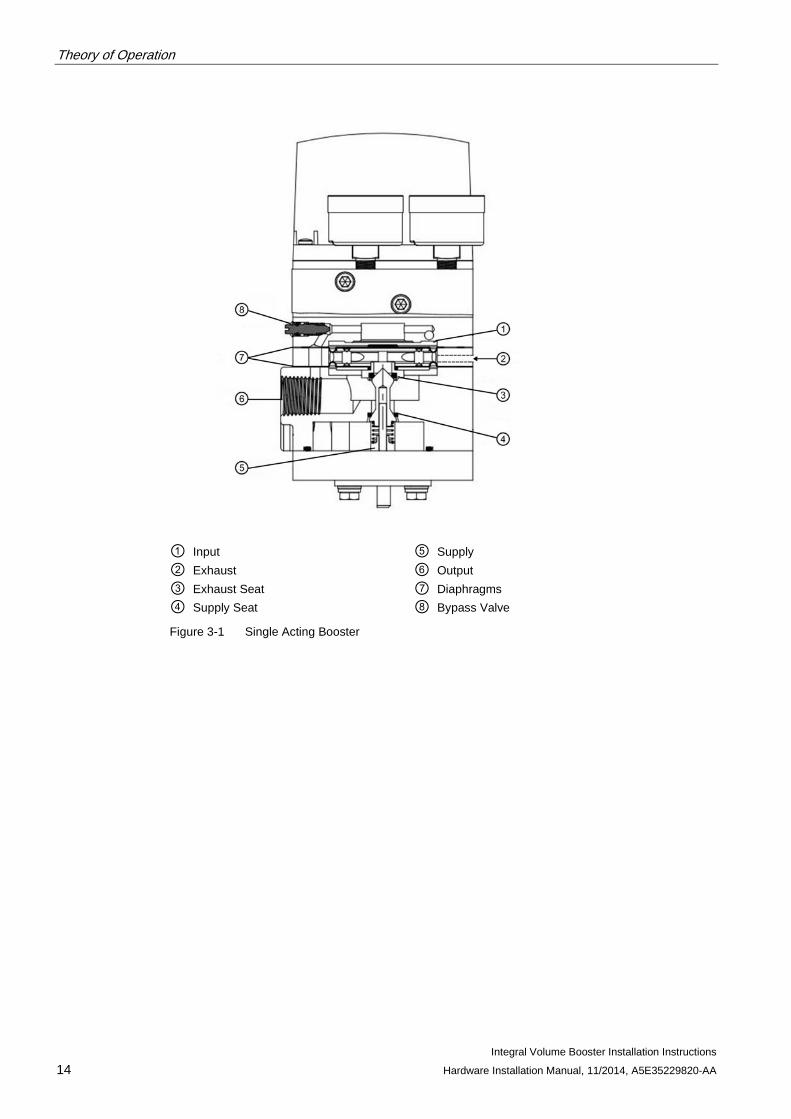
Input pressure from the positioner acting upon the effective area of the upper diaphragm, produces a force which is opposed, in a 1:1 ratio, by the force from output pressure acting on the lower diaphragm. A change in input pressure will create a differential requiring pilot action to re-balance. An increase will depress the diaphragm assembly, opening the pilot valve and admitting supply air to the output until balance is restored. Conversely, a decrease will allow the diaphragm assembly to rise, opening the exhaust seat and lowering the output to match input. These units incorporate a stabilizing bypass needle valve which allows input to pass directly to output for small or gradual input changes. Since the booster is bypassed, there is no loss of accuracy and, with proper needle valve setting, steady-state stability can be maintained. The appropriate needle valve setting depends on the size of the actuator. Typically, the larger the actuator the more the needle valve can be closed and still maintain stability.
Note
The Integral Volume Booster, as well as any other external volume booster, will change the double acting SIPART PS2 operation upon loss of supply air. Without the high flow option module or external volume booster, the double acting PS2 traps output pressure upon loss of supply air. With the Integral Volume Booster or external volume booster, the output pressures are vented and the valve position cannot be determined upon loss of supply air. The Integral Volume Booster has no effect on the SIPART PS2 operation upon loss of control signal or electrical power, see SIPART PS2 manual for details.
Theory of Operation
Integral Volume Booster Installation Instructions 14 Hardware Installation Manual, 11/2014, A5E35229820-AA
① Input ⑤ Supply ② Exhaust ⑥ Output ③ Exhaust Seat ⑦ Diaphragms ④ Supply Seat ⑧ Bypass Valve
Figure 3-1 Single Acting Booster
Integral Volume Booster Installation Instructions Hardware Installation Manual, 11/2014, A5E35229820-AA 15
Installing/mounting 4 4.1 Basic Safety Instructions
WARNING
High operating force with pneumatic actuators
Risk of injury when working on control valves due to the high operating force of the pneumatic actuator. • Please observe the corresponding safety instructions for the pneumatic actuator in use.
WARNING
Lever for position detection
Danger of crushing and shearing with mounting kits which use a lever for position detection. During commissioning and ongoing operation, severing or squeezing of limbs could occur as a result of the lever. Risk of injury when working on control valves due to the high operating force of the pneumatic actuator. • Do not reach into the range of motion of the lever following mounting of the positioner
and mounting kit.
WARNING
Impermissible accessories and spare parts
Danger of explosion in areas subject to explosion hazard. • Only use original accessories or original spare parts. • Observe all relevant installation and safety instructions described in the instructions for
the device or enclosed with the accessory or spare part.
WARNING
It is possible to damage the cover gasket
If the cover gasket is not positioned correctly in the groove of the base plate, it could be damaged when the cover is mounted and screwed tight. • Therefore make sure that the gasket is seated correctly.
Installing/mounting 4.1 Basic Safety Instructions
Integral Volume Booster Installation Instructions 16 Hardware Installation Manual, 11/2014, A5E35229820-AA
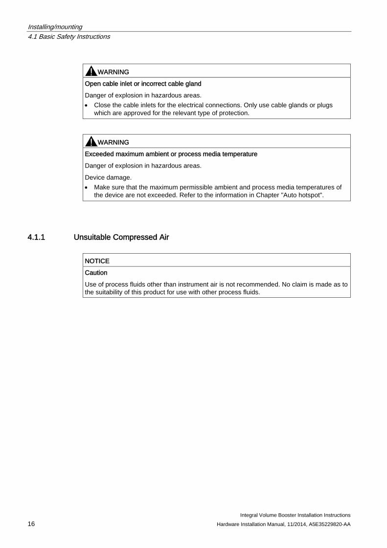
WARNING
Open cable inlet or incorrect cable gland
Danger of explosion in hazardous areas. • Close the cable inlets for the electrical connections. Only use cable glands or plugs
which are approved for the relevant type of protection.
WARNING
Exceeded maximum ambient or process media temperature
Danger of explosion in hazardous areas.
Device damage. • Make sure that the maximum permissible ambient and process media temperatures of
the device are not exceeded. Refer to the information in Chapter "Auto hotspot".
4.1.1 Unsuitable Compressed Air
NOTICE
Caution
Use of process fluids other than instrument air is not recommended. No claim is made as to the suitability of this product for use with other process fluids.
Installing/mounting 4.1 Basic Safety Instructions
Integral Volume Booster Installation Instructions Hardware Installation Manual, 11/2014, A5E35229820-AA 17
4.1.2 Prior to working on the control valve
CAUTION
Please note the following before working on the control valve and when attaching the positioner
Danger of injury. • Prior to working on the control valve, you must move the control valve into a completely
unpressurized. Proceed as follows: – Depressurize the actuator chambers. – Switch off the supply air PZ. – Lock the valve in its position.
• Make sure that the valve has reached the unpressurized state. • If you interrupt the pneumatic auxiliary power to the positioner, the unpressurized
position may only be reached after a certain waiting time. • When mounting, observe the following sequence imperatively to avoid injuries or
mechanical damage to the positioner/mounting kit: – Mount the positioner mechanically. – Connect the electrical auxiliary power supply. – Connect the pneumatic auxiliary power supply. – Commission the positioner.
WARNING
Mechanical impact energy
In order to ensure the degree of protection of the housing (IP66), protect the housing versions of the positioners listed here from mechanical impact energy: • 6DR5..3; not greater than 2 Joule • 6DR5..0; not greater than 1 Joule • 6DR5..1 with inspection window; not greater than 1 Joule
4.1.3 Proper Mounting
NOTICE
Incorrect mounting
The device can be damaged, destroyed, or its functionality impaired through improper mounting. • Before installing ensure there is no visible damage to the device. • Make sure that process connectors are clean, and suitable gaskets and glands are
used. • Mount the device using suitable tools. Refer to the information in Auto hotspot for
installation torque requirements.
Installing/mounting 4.2 Integral Volume Booster
Integral Volume Booster Installation Instructions 18 Hardware Installation Manual, 11/2014, A5E35229820-AA
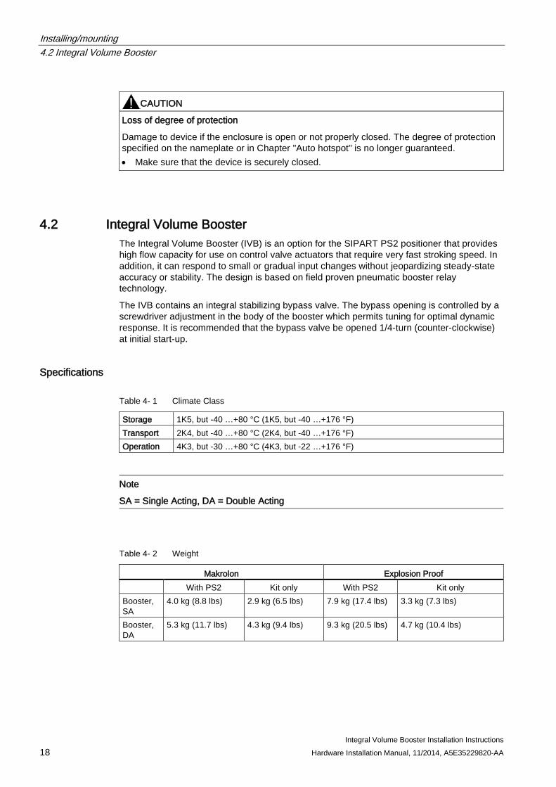
CAUTION
Loss of degree of protection
Damage to device if the enclosure is open or not properly closed. The degree of protection specified on the nameplate or in Chapter "Auto hotspot" is no longer guaranteed. • Make sure that the device is securely closed.
4.2 Integral Volume Booster The Integral Volume Booster (IVB) is an option for the SIPART PS2 positioner that provides high flow capacity for use on control valve actuators that require very fast stroking speed. In addition, it can respond to small or gradual input changes without jeopardizing steady-state accuracy or stability. The design is based on field proven pneumatic booster relay technology.
The IVB contains an integral stabilizing bypass valve. The bypass opening is controlled by a screwdriver adjustment in the body of the booster which permits tuning for optimal dynamic response. It is recommended that the bypass valve be opened 1/4-turn (counter-clockwise) at initial start-up.
Specifications
Table 4- 1 Climate Class
Storage 1K5, but -40 …+80 °C (1K5, but -40 …+176 °F) Transport 2K4, but -40 …+80 °C (2K4, but -40 …+176 °F) Operation 4K3, but -30 …+80 °C (4K3, but -22 …+176 °F)
Note
SA = Single Acting, DA = Double Acting
Table 4- 2 Weight
Makrolon Explosion Proof With PS2 Kit only With PS2 Kit only Booster, SA
4.0 kg (8.8 lbs) 2.9 kg (6.5 lbs) 7.9 kg (17.4 lbs) 3.3 kg (7.3 lbs)
Booster, DA
5.3 kg (11.7 lbs) 4.3 kg (9.4 lbs) 9.3 kg (20.5 lbs) 4.7 kg (10.4 lbs)
Installing/mounting 4.2 Integral Volume Booster
Integral Volume Booster Installation Instructions Hardware Installation Manual, 11/2014, A5E35229820-AA 19
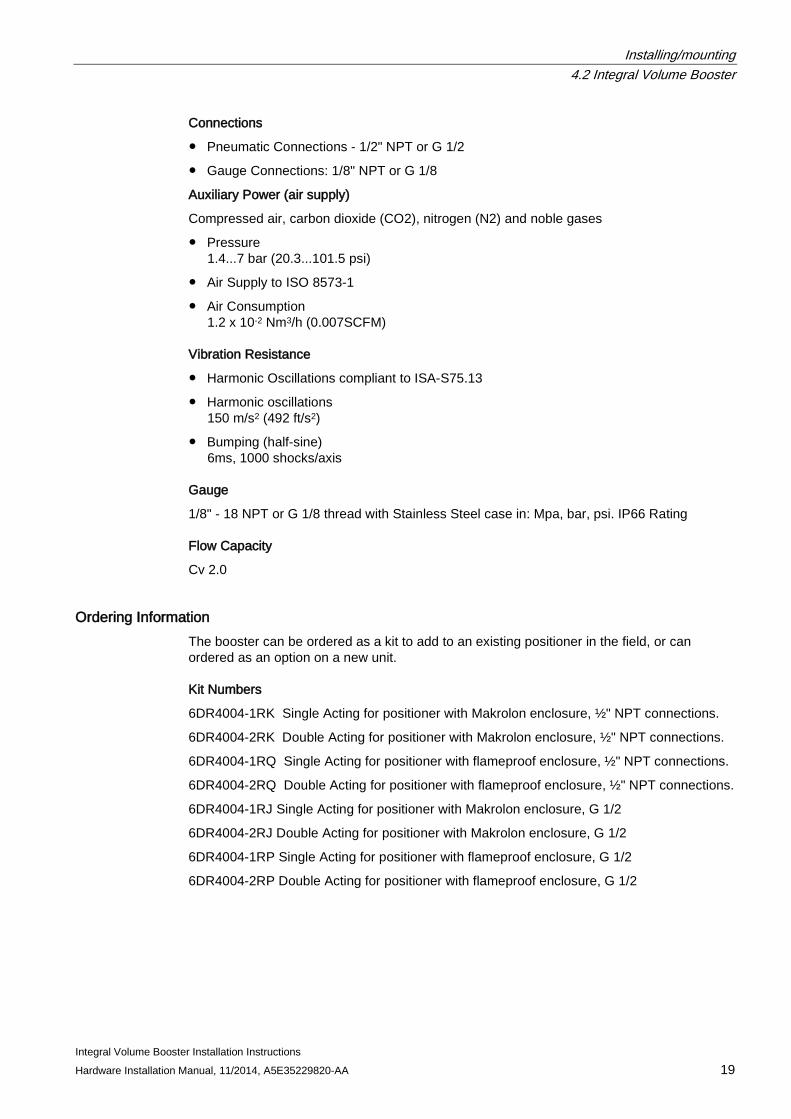
Connections
● Pneumatic Connections - 1/2" NPT or G 1/2
● Gauge Connections: 1/8" NPT or G 1/8
Auxiliary Power (air supply)
Compressed air, carbon dioxide (CO2), nitrogen (N2) and noble gases
● Pressure 1.4...7 bar (20.3...101.5 psi)
● Air Supply to ISO 8573-1
● Air Consumption 1.2 x 10⁻² Nm3/h (0.007SCFM)
Vibration Resistance
● Harmonic Oscillations compliant to ISA-S75.13
● Harmonic oscillations 150 m/s2 (492 ft/s2)
● Bumping (half-sine) 6ms, 1000 shocks/axis
Gauge
1/8" - 18 NPT or G 1/8 thread with Stainless Steel case in: Mpa, bar, psi. IP66 Rating
Flow Capacity
Cv 2.0
Ordering Information The booster can be ordered as a kit to add to an existing positioner in the field, or can ordered as an option on a new unit.
Kit Numbers
6DR4004-1RK Single Acting for positioner with Makrolon enclosure, ½" NPT connections.
6DR4004-2RK Double Acting for positioner with Makrolon enclosure, ½" NPT connections.
6DR4004-1RQ Single Acting for positioner with flameproof enclosure, ½" NPT connections.
6DR4004-2RQ Double Acting for positioner with flameproof enclosure, ½" NPT connections.
6DR4004-1RJ Single Acting for positioner with Makrolon enclosure, G 1/2
6DR4004-2RJ Double Acting for positioner with Makrolon enclosure, G 1/2
6DR4004-1RP Single Acting for positioner with flameproof enclosure, G 1/2
6DR4004-2RP Double Acting for positioner with flameproof enclosure, G 1/2
Installing/mounting 4.3 Installation
Integral Volume Booster Installation Instructions 20 Hardware Installation Manual, 11/2014, A5E35229820-AA
Model Option Codes
R1K Single Acting for positioner with Makrolon enclosure, ½“ NPT connections.
R2K Double Acting for positioner with Makrolon enclosure, ½” NPT connections.
R1Q Single Acting for positioner with flameproof enclosure, ½” NPT connections.
R2Q Double Acting for positioner with flameproof enclosure, ½” NPT connections.
R1J Single Acting for positioner with Makrolon enclosure, G 1/2
R2J Double Acting for positioner with Makrolon enclosure, G 1/2
R1P Single Acting for positioner with flameproof enclosure, G 1/2
R2P Double Acting for positioner with flameproof enclosure, G 1/2
4.3 Installation If the booster kit is to be stocked, stored, or shipped to another location prior to piping, make sure that the factory installed plastic plugs are in the ports to prevent entry of moisture, dirt, or other contaminants.
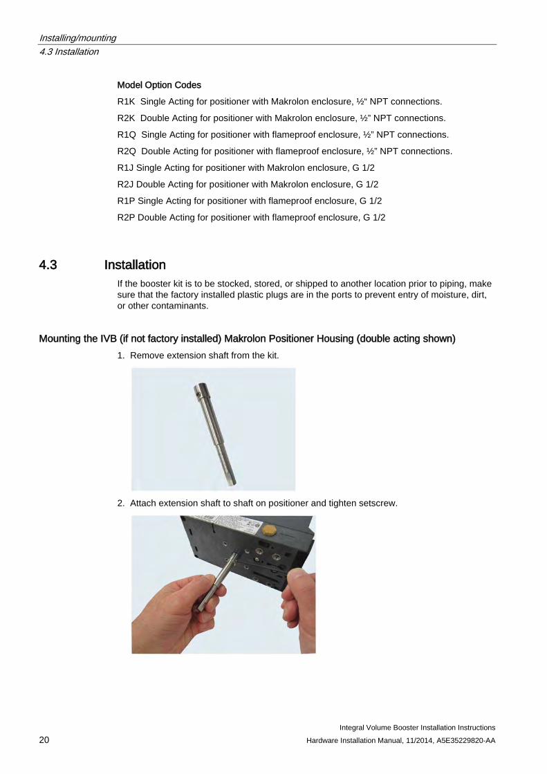
Mounting the IVB (if not factory installed) Makrolon Positioner Housing (double acting shown) 1. Remove extension shaft from the kit.
2. Attach extension shaft to shaft on positioner and tighten setscrew.
Installing/mounting 4.3 Installation
Integral Volume Booster Installation Instructions Hardware Installation Manual, 11/2014, A5E35229820-AA 21
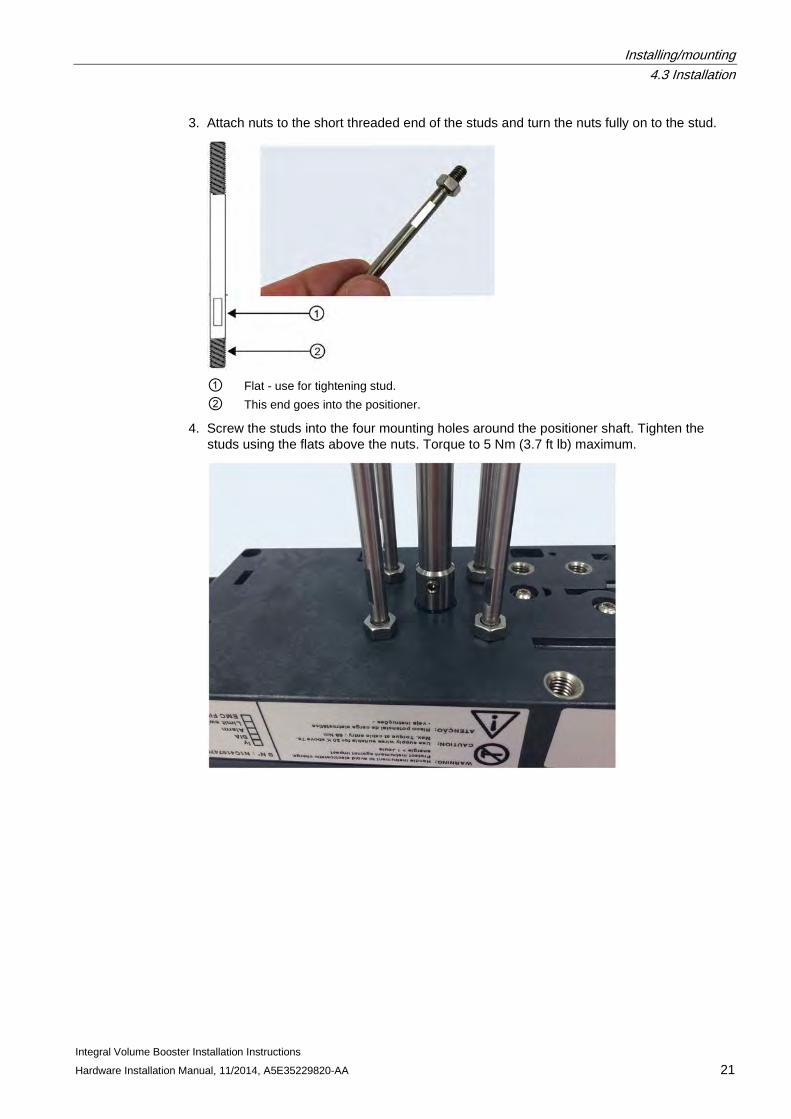
3. Attach nuts to the short threaded end of the studs and turn the nuts fully on to the stud.
① Flat - use for tightening stud. ② This end goes into the positioner.
4. Screw the studs into the four mounting holes around the positioner shaft. Tighten the studs using the flats above the nuts. Torque to 5 Nm (3.7 ft lb) maximum.
Installing/mounting 4.3 Installation
Integral Volume Booster Installation Instructions 22 Hardware Installation Manual, 11/2014, A5E35229820-AA
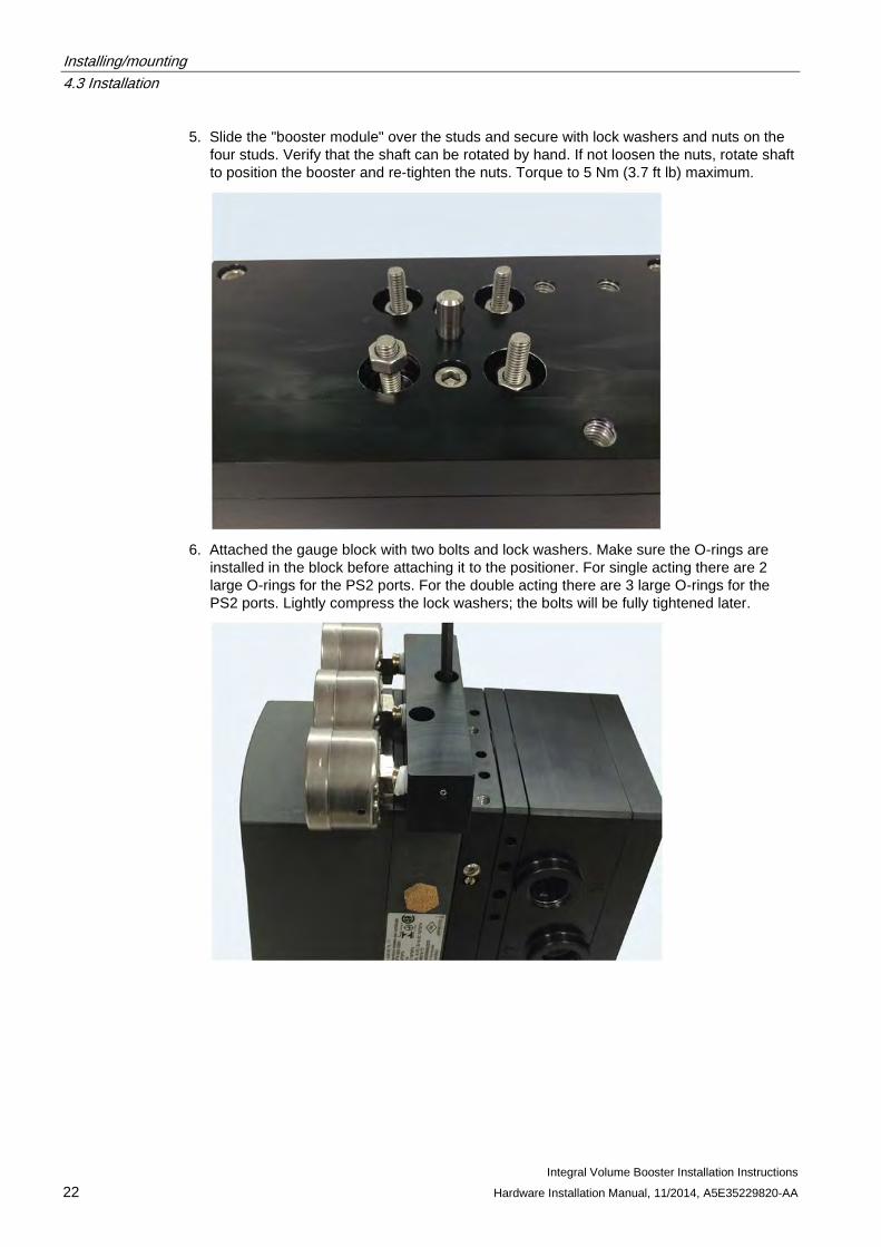
5. Slide the "booster module" over the studs and secure with lock washers and nuts on the four studs. Verify that the shaft can be rotated by hand. If not loosen the nuts, rotate shaft to position the booster and re-tighten the nuts. Torque to 5 Nm (3.7 ft lb) maximum.
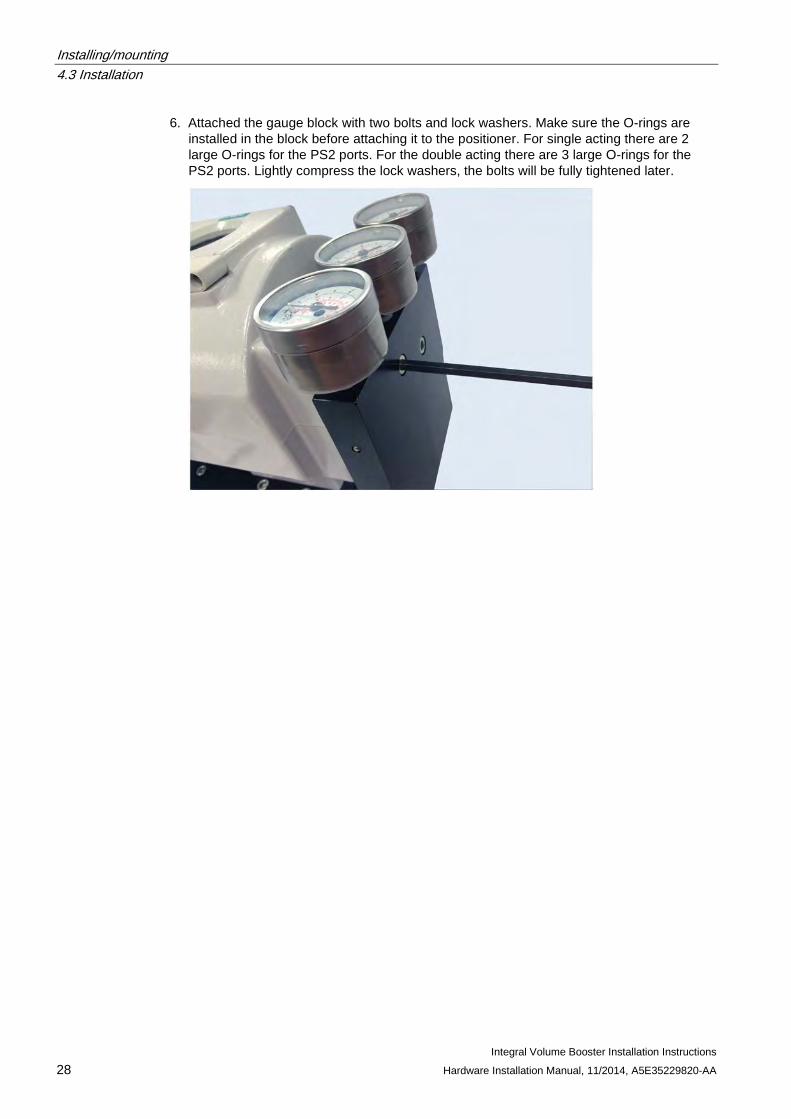
6. Attached the gauge block with two bolts and lock washers. Make sure the O-rings are
installed in the block before attaching it to the positioner. For single acting there are 2 large O-rings for the PS2 ports. For the double acting there are 3 large O-rings for the PS2 ports. Lightly compress the lock washers; the bolts will be fully tightened later.
Installing/mounting 4.3 Installation
Integral Volume Booster Installation Instructions Hardware Installation Manual, 11/2014, A5E35229820-AA 23
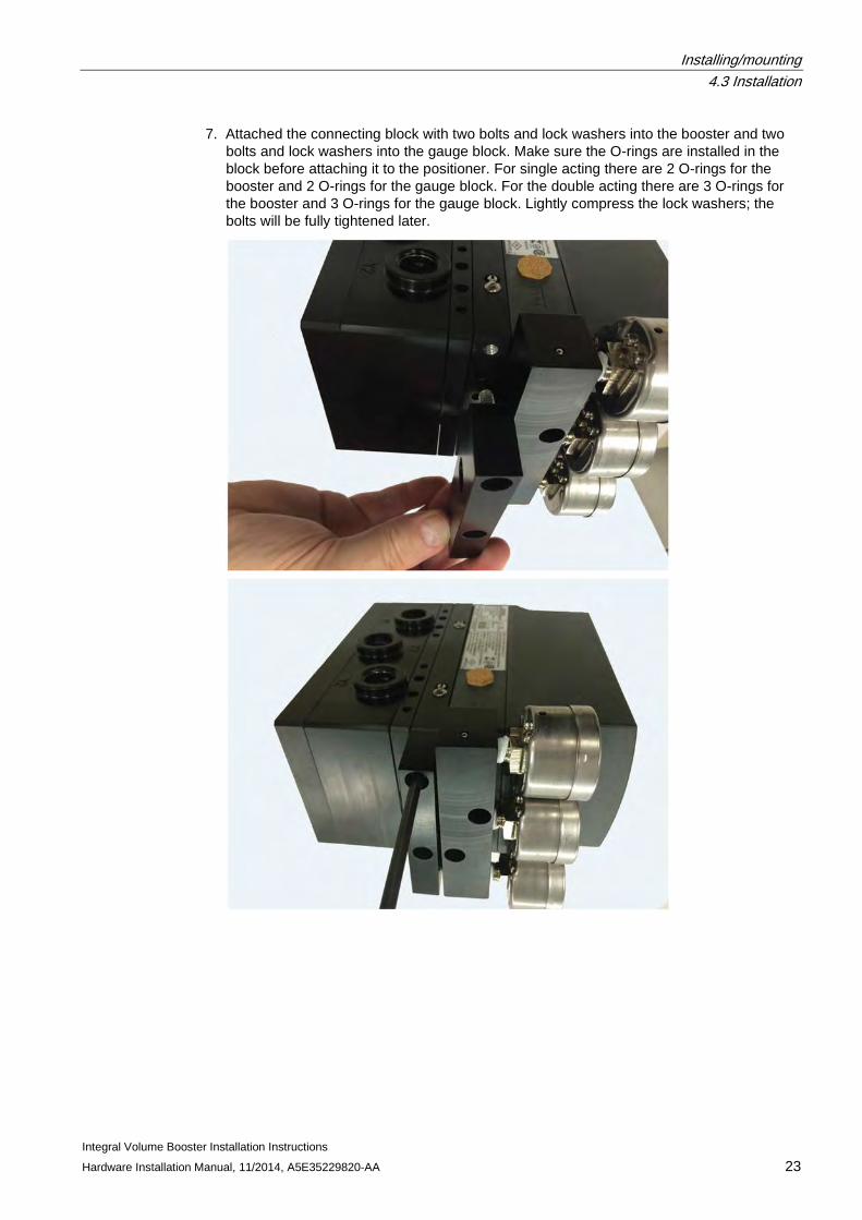
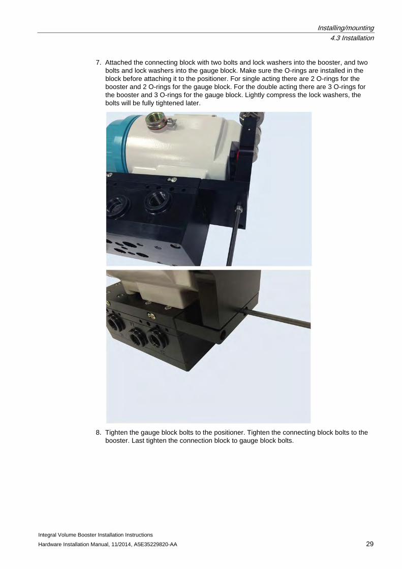
7. Attached the connecting block with two bolts and lock washers into the booster and two bolts and lock washers into the gauge block. Make sure the O-rings are installed in the block before attaching it to the positioner. For single acting there are 2 O-rings for the booster and 2 O-rings for the gauge block. For the double acting there are 3 O-rings for the booster and 3 O-rings for the gauge block. Lightly compress the lock washers; the bolts will be fully tightened later.
Installing/mounting 4.3 Installation
Integral Volume Booster Installation Instructions 24 Hardware Installation Manual, 11/2014, A5E35229820-AA
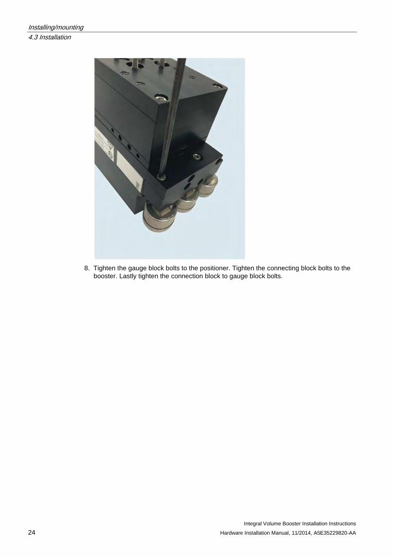
8. Tighten the gauge block bolts to the positioner. Tighten the connecting block bolts to the
booster. Lastly tighten the connection block to gauge block bolts.
Installing/mounting 4.3 Installation
Integral Volume Booster Installation Instructions Hardware Installation Manual, 11/2014, A5E35229820-AA 25
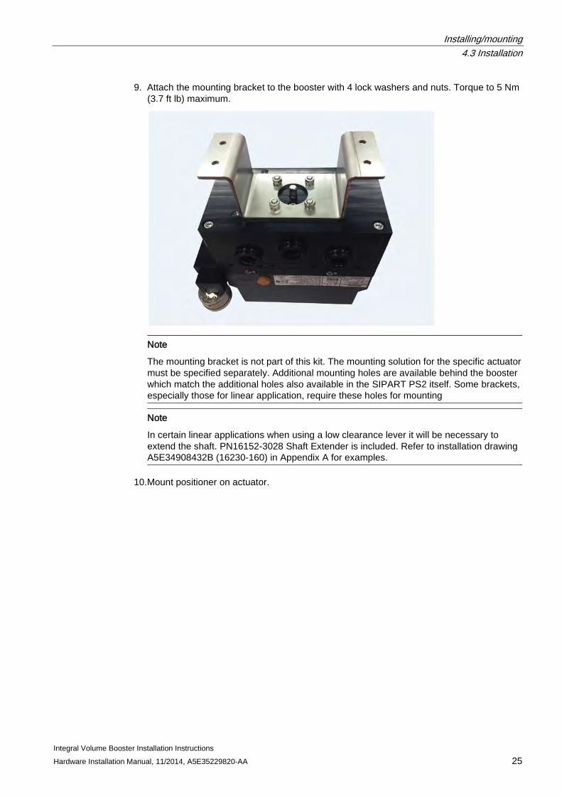
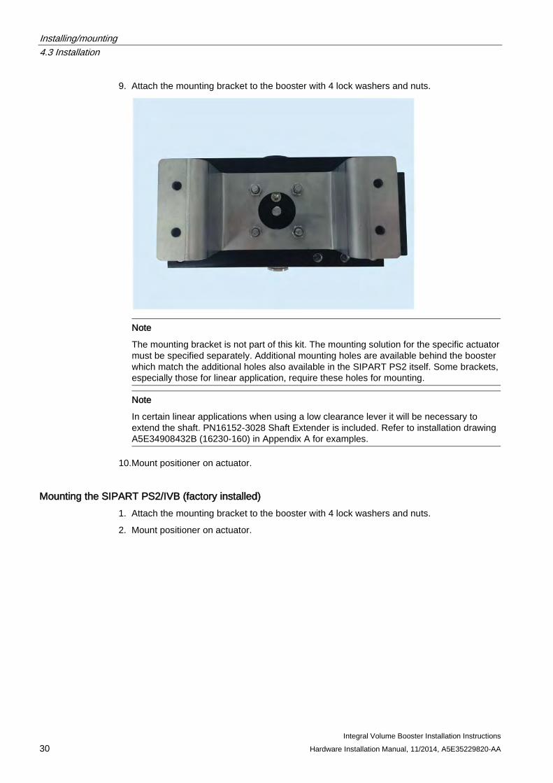
9. Attach the mounting bracket to the booster with 4 lock washers and nuts. Torque to 5 Nm (3.7 ft lb) maximum.
Note
The mounting bracket is not part of this kit. The mounting solution for the specific actuator must be specified separately. Additional mounting holes are available behind the booster which match the additional holes also available in the SIPART PS2 itself. Some brackets, especially those for linear application, require these holes for mounting
Note
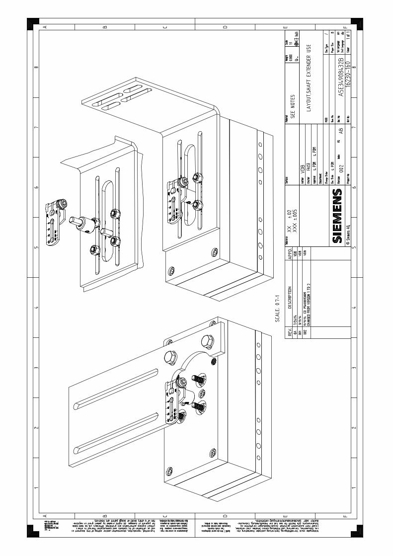
In certain linear applications when using a low clearance lever it will be necessary to extend the shaft. PN16152-3028 Shaft Extender is included. Refer to installation drawing A5E34908432B (16230-160) in Appendix A for examples.
10.Mount positioner on actuator.
Installing/mounting 4.3 Installation
Integral Volume Booster Installation Instructions 26 Hardware Installation Manual, 11/2014, A5E35229820-AA
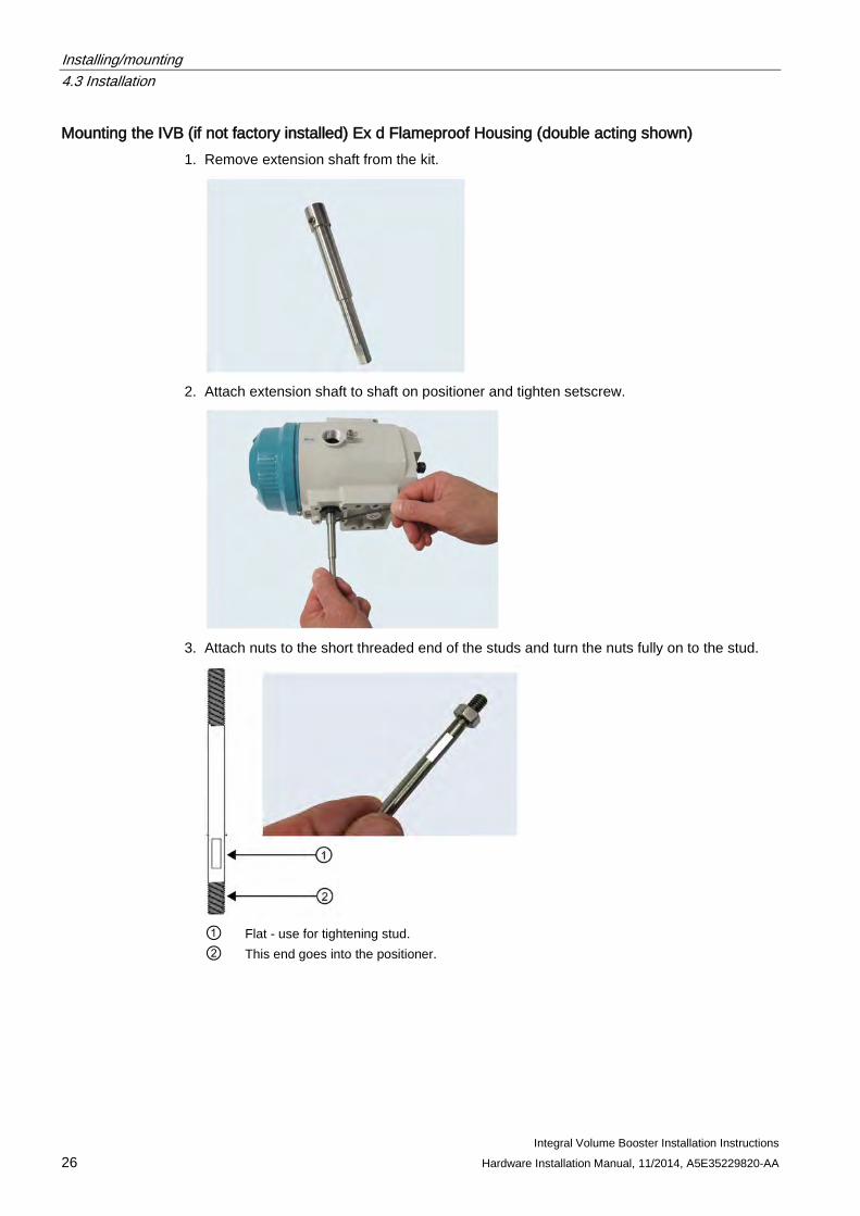
Mounting the IVB (if not factory installed) Ex d Flameproof Housing (double acting shown) 1. Remove extension shaft from the kit.
2. Attach extension shaft to shaft on positioner and tighten setscrew.
3. Attach nuts to the short threaded end of the studs and turn the nuts fully on to the stud.
① Flat - use for tightening stud. ② This end goes into the positioner.
Installing/mounting 4.3 Installation
Integral Volume Booster Installation Instructions Hardware Installation Manual, 11/2014, A5E35229820-AA 27
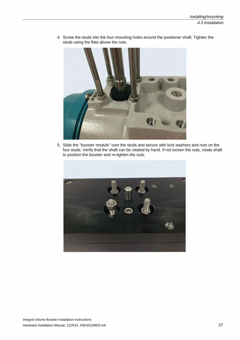
4. Screw the studs into the four mounting holes around the positioner shaft. Tighten the studs using the flats above the nuts.
5. Slide the "booster module" over the studs and secure with lock washers and nuts on the
four studs. Verify that the shaft can be rotated by hand. If not loosen the nuts, rotate shaft to position the booster and re-tighten the nuts.
Installing/mounting 4.3 Installation
Integral Volume Booster Installation Instructions 28 Hardware Installation Manual, 11/2014, A5E35229820-AA
6. Attached the gauge block with two bolts and lock washers. Make sure the O-rings are installed in the block before attaching it to the positioner. For single acting there are 2 large O-rings for the PS2 ports. For the double acting there are 3 large O-rings for the PS2 ports. Lightly compress the lock washers, the bolts will be fully tightened later.
Installing/mounting 4.3 Installation
Integral Volume Booster Installation Instructions Hardware Installation Manual, 11/2014, A5E35229820-AA 29
7. Attached the connecting block with two bolts and lock washers into the booster, and two bolts and lock washers into the gauge block. Make sure the O-rings are installed in the block before attaching it to the positioner. For single acting there are 2 O-rings for the booster and 2 O-rings for the gauge block. For the double acting there are 3 O-rings for the booster and 3 O-rings for the gauge block. Lightly compress the lock washers, the bolts will be fully tightened later.
8. Tighten the gauge block bolts to the positioner. Tighten the connecting block bolts to the
booster. Last tighten the connection block to gauge block bolts.
Installing/mounting 4.3 Installation
Integral Volume Booster Installation Instructions 30 Hardware Installation Manual, 11/2014, A5E35229820-AA
9. Attach the mounting bracket to the booster with 4 lock washers and nuts.
Note
The mounting bracket is not part of this kit. The mounting solution for the specific actuator must be specified separately. Additional mounting holes are available behind the booster which match the additional holes also available in the SIPART PS2 itself. Some brackets, especially those for linear application, require these holes for mounting.
Note
In certain linear applications when using a low clearance lever it will be necessary to extend the shaft. PN16152-3028 Shaft Extender is included. Refer to installation drawing A5E34908432B (16230-160) in Appendix A for examples.
10.Mount positioner on actuator.
Mounting the SIPART PS2/IVB (factory installed) 1. Attach the mounting bracket to the booster with 4 lock washers and nuts.
2. Mount positioner on actuator.
Installing/mounting 4.4 Pneumatic Connections
Integral Volume Booster Installation Instructions Hardware Installation Manual, 11/2014, A5E35229820-AA 31
4.4 Pneumatic Connections Refer to installation drawing (assembly with dimensions) for the locations of the pneumatic connections. The supply and output connections are 1/2" NPT or G 1/2. Ideally the SIPART PS2/IVB assembly should be close coupled to the actuator. Tubing of 1/2" O.D. or larger is recommended for piping. Blow out all piping before connections are made to prevent the possibility of dirt or chips entering the relay. Use pipe sealant sparingly, and then only on the male threads. A non-hardening sealant is strongly recommended. Connect the relay to a source of clean, dry, oil-free instrument air. See Instrument Air Requirements.
NOTICE
Caution
Pressure in excess of 7 bar (101.5 psi)i to any connection may cause damage to the relay. In any event, maximum actuator pressure should never be exceeded.
Instrument Air Requirements
NOTICE
Caution
Use of process fluids other than instrument air is not recommended. No claim is made as to the suitability of this product for use with other process fluids.
NOTICE
Caution
Synthetic compressor lubricants in the air system at the instrument may cause the instrument to fail.
There are many types of synthetic compressor lubricants. Some may not be compatible with materials used in construction of the relay. Wetting of these materials with such an oil mist or oil vapor, etc., may cause deterioration and may ultimately result in the failure of the instrument. Refer to Specifications for a list of materials.
The requirements for a quality air supply can be found in the International Organization for Standardization (ISO) 8573-1.
Installing/mounting 4.5 Device Setup
Integral Volume Booster Installation Instructions 32 Hardware Installation Manual, 11/2014, A5E35229820-AA
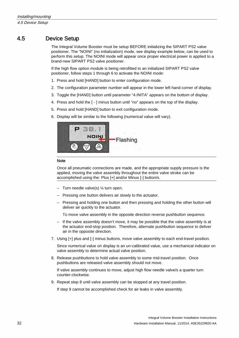
4.5 Device Setup The Integral Volume Booster must be setup BEFORE initializing the SIPART PS2 valve positioner. The “NOINI” (no initialization) mode, see display example below, can be used to perform this setup. The NOINI mode will appear once proper electrical power is applied to a brand-new SIPART PS2 valve positioner.
If the high flow option module is being retrofitted to an initialized SIPART PS2 valve positioner, follow steps 1 through 6 to activate the NOINI mode:
1. Press and hold [HAND] button to enter configuration mode.
2. The configuration parameter number will appear in the lower left hand corner of display.
3. Toggle the [HAND] button until parameter “4.INITA” appears on the bottom of display.
4. Press and hold the [ - ] minus button until “no” appears on the top of the display.
5. Press and hold [HAND] button to exit configuration mode.
6. Display will be similar to the following (numerical value will vary).
Note
Once all pneumatic connections are made, and the appropriate supply pressure is the applied, moving the valve assembly throughout the entire valve stroke can be accomplished using the: Plus [+] and/or Minus [-] button/s.
– Turn needle valve(s) ¼ turn open.
– Pressing one button delivers air slowly to the actuator.
– Pressing and holding one button and then pressing and holding the other button will deliver air quickly to the actuator.
To move valve assembly in the opposite direction reverse pushbutton sequence.
– If the valve assembly doesn’t move, it may be possible that the valve assembly is at the actuator end-stop position. Therefore, alternate pushbutton sequence to deliver air in the opposite direction.
7. Using [+] plus and [-] minus buttons, move valve assembly to each end-travel position.
Since numerical value on display is an un-calibrated value, use a mechanical indicator on valve assembly to determine actual valve position.
8. Release pushbuttons to hold valve assembly to some mid-travel position. Once pushbuttons are released valve assembly should not move.
If valve assembly continues to move, adjust high flow needle valve/s a quarter turn counter-clockwise.
9. Repeat step 8 until valve assembly can be stopped at any travel position.
If step 9 cannot be accomplished check for air leaks in valve assembly.
Installing/mounting 4.5 Device Setup
Integral Volume Booster Installation Instructions Hardware Installation Manual, 11/2014, A5E35229820-AA 33
10.Setup of High flow option module is complete once valve assembly can be stopped at any travel position by releasing pushbuttons.
11.Using SIPART PS2 leaflet instructions or manual, initialize SIPART PS2 valve positioner.
Installing/mounting 4.5 Device Setup
Integral Volume Booster Installation Instructions 34 Hardware Installation Manual, 11/2014, A5E35229820-AA
Integral Volume Booster Installation Instructions Hardware Installation Manual, 11/2014, A5E35229820-AA 35
Service and maintenance 5 5.1 Maintenance
These instruments do not normally require any routine maintenance.
NOTICE
Caution
Before disassembling the unit, make sure all air pressure to the unit is turned off
Screens The screens are located in the air supply and output connections. A screen must be removed from its seat to be cleaned. Screens can be damaged during removal, and spare screens should be on hand (P/N A5E35246369).
1. Turn supply air off.
2. Remove a screen with a scribe by carefully pulling on and around the edge of the screen.
3. Clean the screen by blowing through in the reverse direction with compressed air. Soak in solvent or clean mechanically if necessary.
4. Insert the screen until it bottoms using an object, such as the eraser end of a pencil, which will not cause damage.
Shipping and Storage If the booster kit is to be stocked, stored, or shipped to another location prior to piping, make sure that the factory installed plastic plugs are in the ports to prevent entry of moisture, dirt, or other contaminants.
Customer/Product Support This section provides the Internet site addresses, e-mail addresses, telephone numbers, and related information for customers to access Siemens product support.
Service and maintenance 5.1 Maintenance
Integral Volume Booster Installation Instructions 36 Hardware Installation Manual, 11/2014, A5E35229820-AA
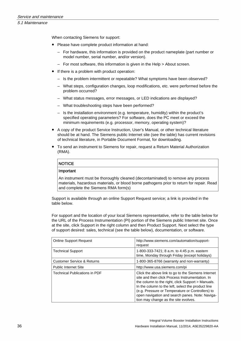
When contacting Siemens for support:
● Please have complete product information at hand:
– For hardware, this information is provided on the product nameplate (part number or model number, serial number, and/or version).
– For most software, this information is given in the Help > About screen.
● If there is a problem with product operation:
– Is the problem intermittent or repeatable? What symptoms have been observed?
– What steps, configuration changes, loop modifications, etc. were performed before the problem occurred?
– What status messages, error messages, or LED indications are displayed?
– What troubleshooting steps have been performed?
– Is the installation environment (e.g. temperature, humidity) within the product’s specified operating parameters? For software, does the PC meet or exceed the minimum requirements (e.g. processor, memory, operating system)?
● A copy of the product Service Instruction, User’s Manual, or other technical literature should be at hand. The Siemens public Internet site (see the table) has current revisions of technical literature, in Portable Document Format, for downloading.
● To send an instrument to Siemens for repair, request a Return Material Authorization (RMA).
NOTICE
Important
An instrument must be thoroughly cleaned (decontaminated) to remove any process materials, hazardous materials, or blood borne pathogens prior to return for repair. Read and complete the Siemens RMA form(s)
Support is available through an online Support Request service; a link is provided in the table below.
For support and the location of your local Siemens representative, refer to the table below for the URL of the Process Instrumentation (PI) portion of the Siemens public Internet site. Once at the site, click Support in the right column and then Product Support. Next select the type of support desired: sales, technical (see the table below), documentation, or software. Online Support Request http://www.siemens.com/automation/support-
request Technical Support 1-800-333-7421; 8 a.m. to 4:45 p.m. eastern
time, Monday through Friday (except holidays) Customer Service & Returns 1-800-365-8766 (warranty and non-warranty) Public Internet Site http://www.usa.siemens.com/pi Technical Publications in PDF Click the above link to go to the Siemens Internet
site and then click Process Instrumentation. In the column to the right, click Support > Manuals. In the column to the left, select the product line (e.g. Pressure or Temperature or Controllers) to open navigation and search panes. Note: Naviga-tion may change as the site evolves.

Service and maintenance 5.1 Maintenance
Integral Volume Booster Installation Instructions Hardware Installation Manual, 11/2014, A5E35229820-AA 37
Service and maintenance 5.1 Maintenance
Integral Volume Booster Installation Instructions 38 Hardware Installation Manual, 11/2014, A5E35229820-AA
Integral Volume Booster Installation Instructions Hardware Installation Manual, 11/2014, A5E35229820-AA 39
Dimension drawings 6 6.1 Installation and Outline Drawings
The following installation drawings are used with this device:
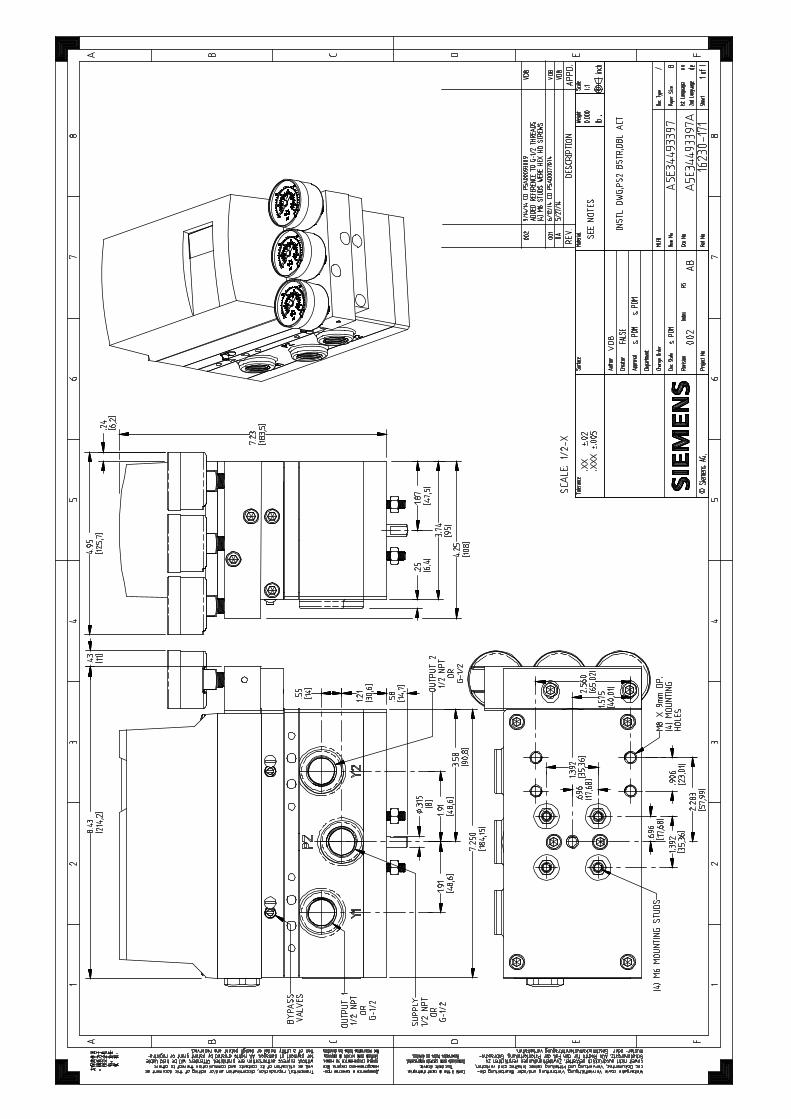
A5E34493397A Rev AB - Installation Drawing, PS2 Double Acting Booster (16230-171)
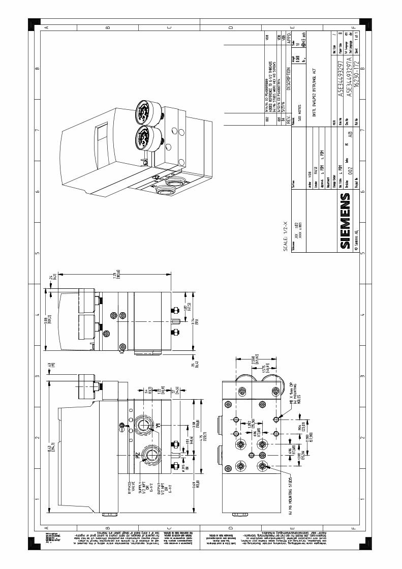
A5E34493297A Rev AB - Installation Drawing, PS2 Single Acting Booster (16230-172)
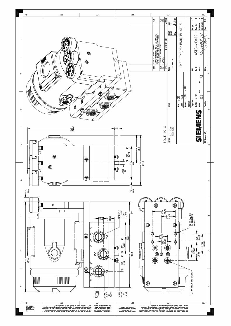
A5E34493407A Rev AB - Installation Drawing, PS2 Double Acting Booster, FP (16230-173)
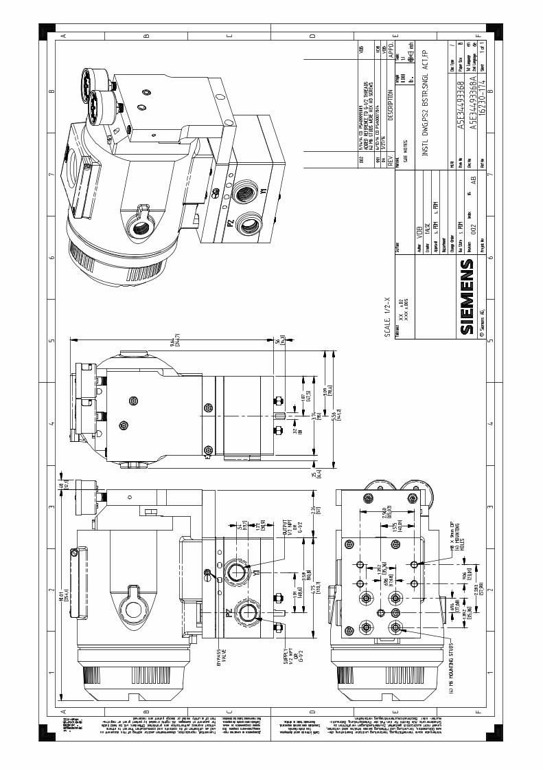
A5E34493368A Rev AB - Installation Drawing, PS2 Single Acting Booster, FP (16230-174)
A5E34908432B Rev AB - Installation Drawing, Layout, PS2 Shaft Extender Use (16230-160)
Dimension drawings 6.1 Installation and Outline Drawings
Integral Volume Booster Installation Instructions 40 Hardware Installation Manual, 11/2014, A5E35229820-AA

Integral Volume Booster Installation Instructions Hardware Installation Manual, 11/2014, A5E35229820-AA 41
Index
A Auxiliary Power, 19
C Certificates, 10 Connections, 19 Correct usage, (See improper device modifications) Customer Support, 35
D Drawings
Installation and Outline, 39
F Flow Capacity, 19
G Gauge, 19
H Hazardous area
Laws and directives, 10 History, 5
I Improper device modifications, 10 Industries, 5 Installation Procedures, 20 Instrument Air Requirements, 31 Integral Volume Booster, 18
K Kit numbers, 19
M Maintenance and Service, 35 Model Option Codes, 20
N NOINI Mode, 32
O Ordering Information, 19
P Pneumatic Connections, 31
Q Qualified personnel, 10
S Scope of delivery, 6 Screens
Cleaning, 35 Shipping and Storage, 35 Specifications, 18 Symbols, (Refer to warning symbols)
T Test certificates, 10 Theory of Operation, 13
V Vibration Resistance, 19
W Warning symbols, 9 Warranty, 7 Weight, 18


Subject to change without prior noticeOrder No.: A5E35229820Lit. No.: A5E35229820-AA 11.2014 All rights reserved Printed in USA© 2014 Siemens Industry, Inc.
Siemens Industry, Inc.Industry Automation DivisionValve PositionerSpring House, PA 19477USA
www.siemens.com/processautomation
For more information
www.siemens.de\sipartps2