insulators, conductors, transformer and ac motors
TRANSCRIPT
INSULATORS
By:- CH. SRIKANTH
• An electrical insulator is a material whose internal electric charges do not flow freely, and which therefore does not conduct an electric current, under the influence of an electric field.
• A perfect insulator does not exist, but some materials such as glass, paper and Teflon, which have high resistivity, are very good electrical insulators.
• Insulators are used in electrical equipment to support and separate electrical conductors without allowing current through themselves.
TYPES OF INSULATORS
There are several types of insulators but the most commonly used are :•Pin Insulator•Suspension Insulator•Strain Insulator and•Shackle insulator.
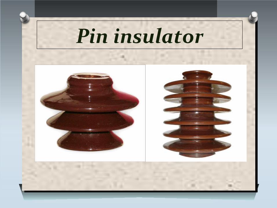
Pin insulator
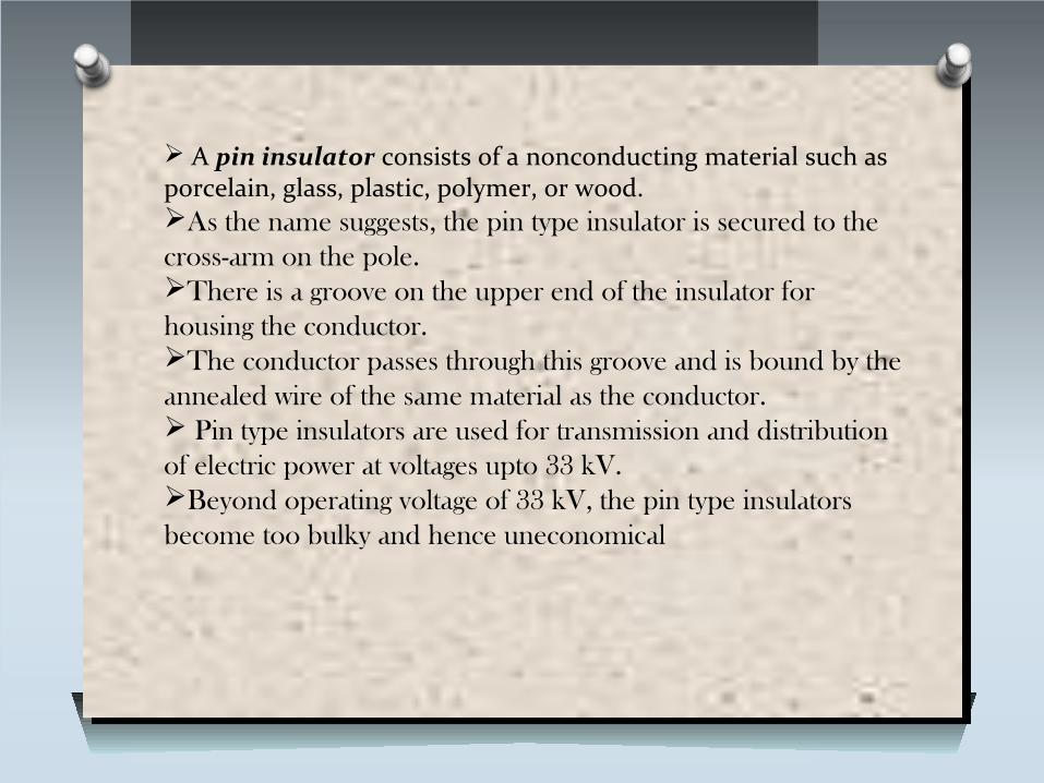
A pin insulator consists of a nonconducting material such as porcelain, glass, plastic, polymer, or wood.As the name suggests, the pin type insulator is secured to the cross-arm on the pole.There is a groove on the upper end of the insulator for housing the conductor. The conductor passes through this groove and is bound by the annealed wire of the same material as the conductor. Pin type insulators are used for transmission and distribution of electric power at voltages upto 33 kV. Beyond operating voltage of 33 kV, the pin type insulators become too bulky and hence uneconomical
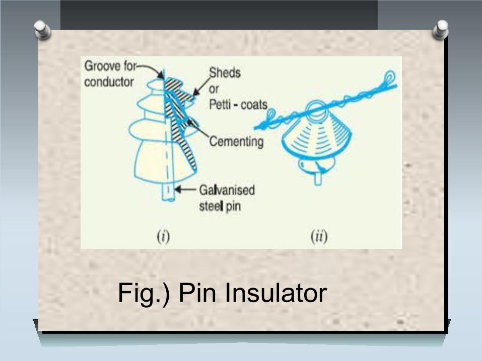
Fig.) Pin Insulator
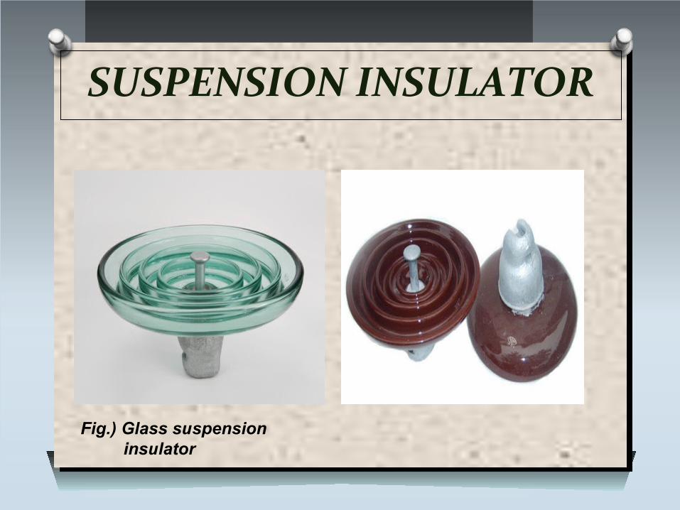
SUSPENSION INSULATOR
Fig.) Glass suspension insulator
For high voltages (>33 kV), it is a usual practice to use suspension type insulators consist of a number of porcelain discs connected in series by metal links in the form of a string.
The conductor is suspended at the bottom end of this string while the other end of the string is secured to the cross-arm of the tower.
Each unit or disc is designed for low voltage, say 11 kV. The number of discs in series would obviously depend
upon the working voltage. For instance, if the working voltage is 66 kV, then six discs
in series will be provided on the string.
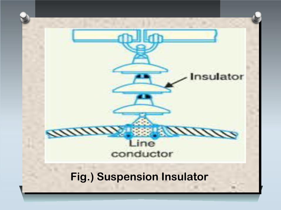
Fig.) Suspension Insulator
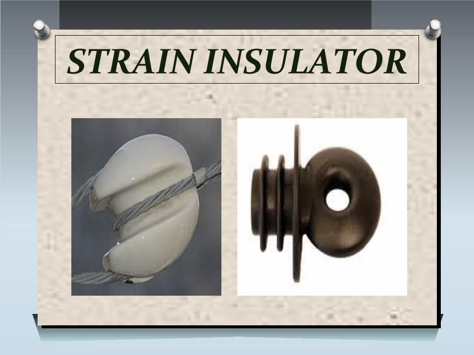
STRAIN INSULATOR
When there is a dead end of the line or there is corner or sharp curve, the line is subjected to greater tension.
In order to relieve the line of excessive tension, strain insulators are used.
For low voltage lines (< 11 kV), shackle insulators are used as strain insulators.
However, for high voltage transmission lines, strain insulator consists of an assembly of suspension insulators as shown in Figure.
The discs of strain insulators are used in the vertical plane. When the tension in lines is exceedingly high, at long river
spans, two or more strings are used in parallel.
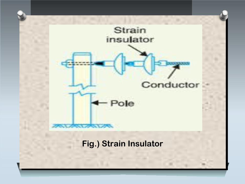
Fig.) Strain Insulator
SHACKLE INSULATOR
In early days, the shackle insulators were used as strain insulators.
But now a days, they are frequently used for low voltage distribution lines.
Such insulators can be used either in a horizontal position or in a vertical position.
They can be directly fixed to the pole with a bolt or to the cross arm.
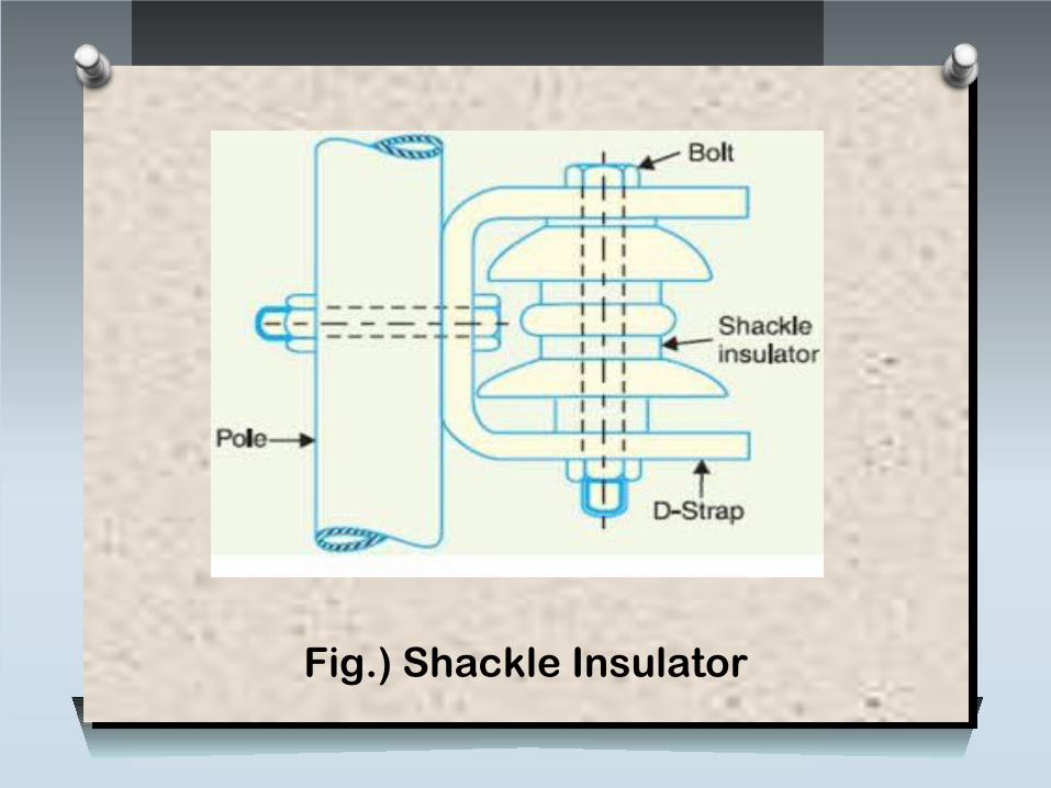
Fig.) Shackle Insulator
CONDUCTORS
TYPES OF CONDUCTORS
O SOLID CONDUCTORSO HOLLOW CONDUCTORSO STRANDED/BUNDLED CONDUCTORSO UNDER GROUND CABLES
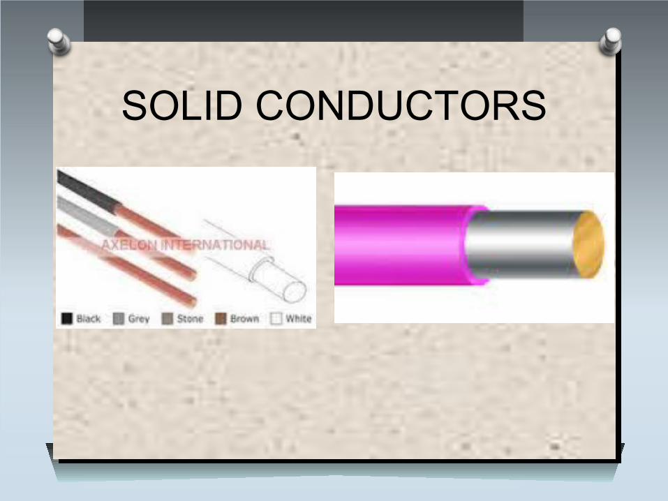
SOLID CONDUCTORS
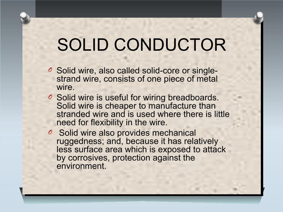
SOLID CONDUCTORO Solid wire, also called solid-core or single-
strand wire, consists of one piece of metal wire.
O Solid wire is useful for wiring breadboards. Solid wire is cheaper to manufacture than stranded wire and is used where there is little need for flexibility in the wire.
O Solid wire also provides mechanical ruggedness; and, because it has relatively less surface area which is exposed to attack by corrosives, protection against the environment.
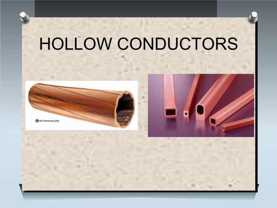
HOLLOW CONDUCTORS
HOLLOW CONDUCTORSO Hollow conductors are used to reduce corona
losses and skin effect.O These are used rarely.
APPLICATIONS :O GeneratorsO Induction furnacesO Plasma research devicesO Electrodynamic vibration test systems
BUNDLED/STRANDED CONDUCTORS
BUNDLED/STRANDED CONDUCTORS
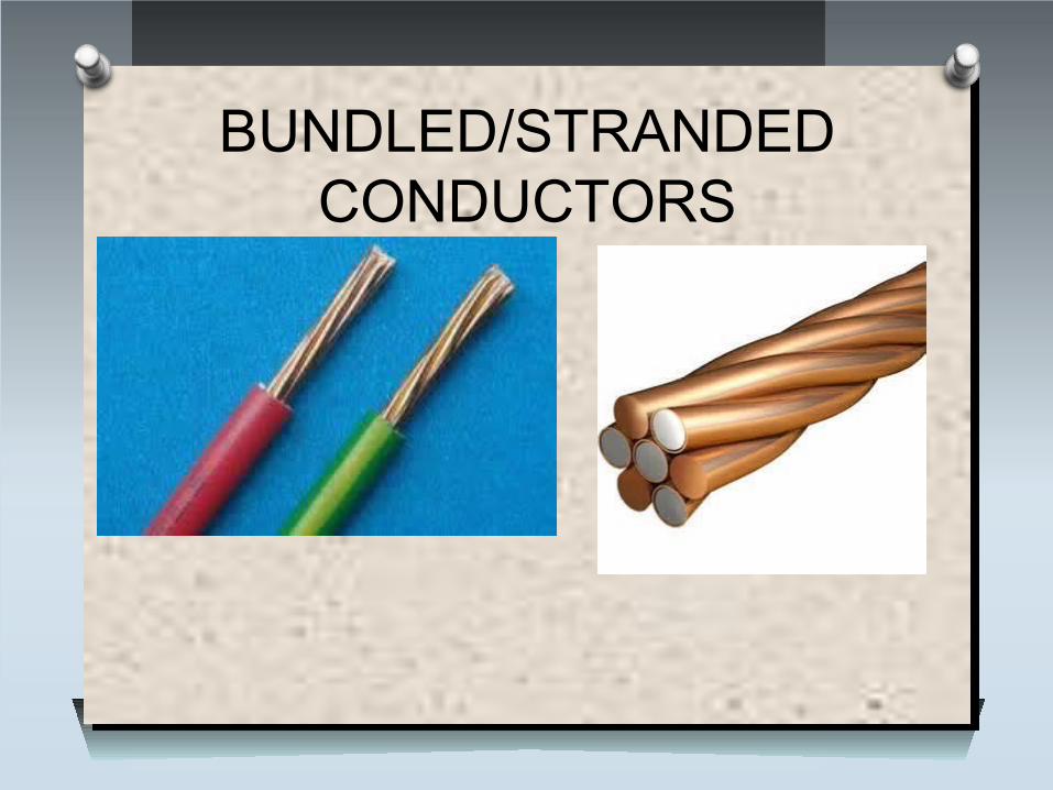
O Bundled/Stranded wire is composed of a number of small gauge wire bundled or wrapped together to form a larger conductor.
O Stranded wire is more flexible than solid wire of the same total cross-sectional area.
O Stranded wire tends to be a better conductor than solid wire because the individual wires collectively comprise a greater surface area.
O Stranded wire is used when higher resistance to metal fatigue is required.
UNDER GROUND CABLES
UNDER GROUND CABLES
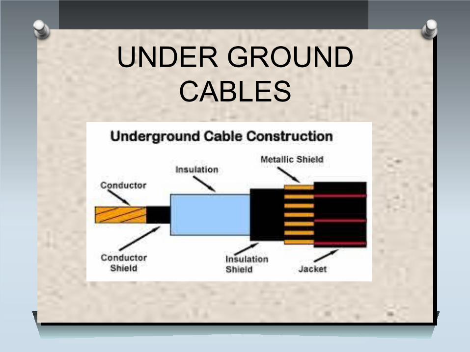
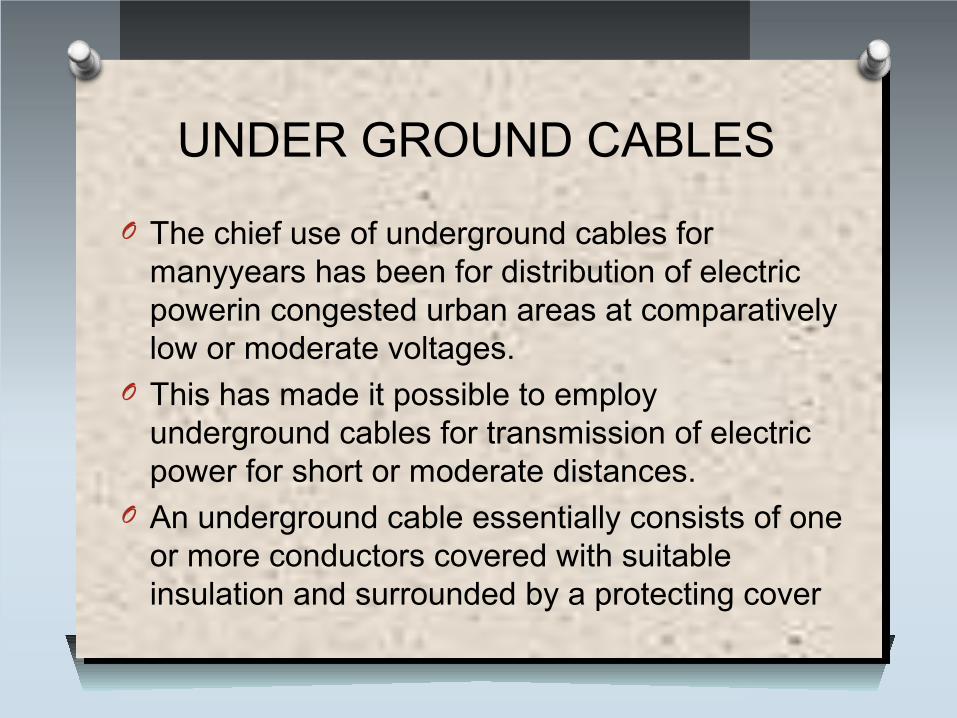
O The chief use of underground cables for manyyears has been for distribution of electric powerin congested urban areas at comparatively low or moderate voltages.
O This has made it possible to employ underground cables for transmission of electric power for short or moderate distances.
O An underground cable essentially consists of one or more conductors covered with suitable insulation and surrounded by a protecting cover
TRANSFORMERS
introduction
O A transformer is a device that changes ac electric power at one voltage level to ac electric power at another voltage level through the action of a magnetic field.
O There are two or more stationary electric circuits that are coupled magnetically.
O Transformers provide much needed capability of changing the voltage and current levels easily.O They are used to step-up generator voltage to an
appropriate voltage level for power transfer.O Stepping down the transmission voltage at various levels
for distribution and power utilization.
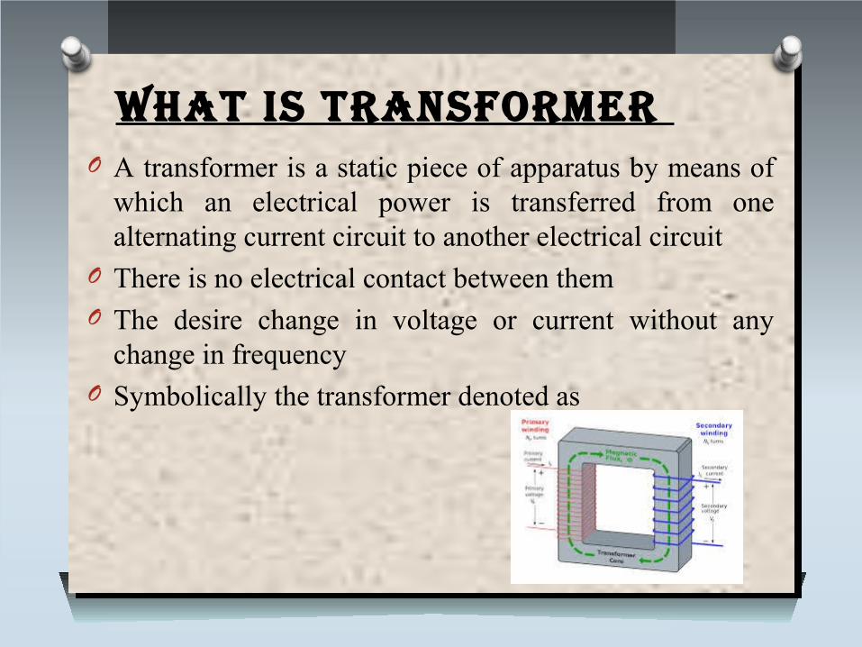
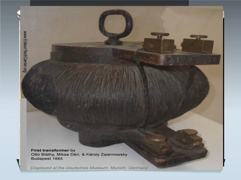
What is transformer O A transformer is a static piece of apparatus by means of
which an electrical power is transferred from one alternating current circuit to another electrical circuit
O There is no electrical contact between themO The desire change in voltage or current without any
change in frequency O Symbolically the transformer denoted as
structure of transformerO The transformer two inductive coils ,these are electrical
separated but linked through a common magnetic current circuit
O These two coils have a high mutual inductionO One of the two coils is connected of alternating voltage
.this coil in which electrical energy is fed with the help of source called primary winding (P) shown in fig.
O The other winding is connected to a load the electrical energy is transformed to this winding drawn out to the load .this winding is called secondary winding(S) shown in fig.
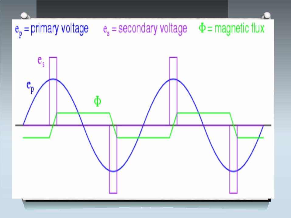
Working principle
O The transformer works in the principle of mutual induction
O When the alternating current flows in the primary coils, a changing magnetic flux is generated around the primary coil.
O The changing magnetic flux is transferred to the secondary coil through the iron core
O The changing magnetic flux is cut by the secondary coil, hence induces an e.m.f in the secondary coil
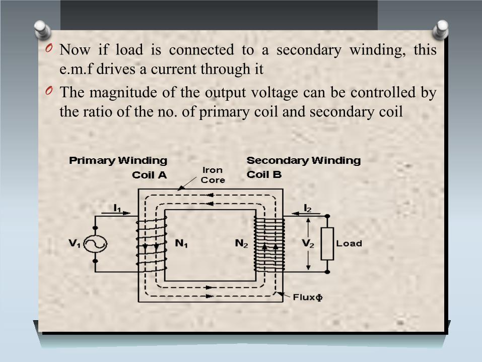
O Now if load is connected to a secondary winding, this e.m.f drives a current through it
O The magnitude of the output voltage can be controlled by the ratio of the no. of primary coil and secondary coil
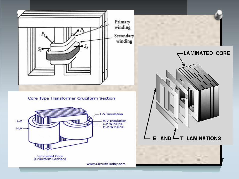
construction of transformerO These are two basic of transformer construction O Magnetic core O Windings or coilsO Magnetic core O The core of transformer either square or rectangular type
in size.It is further divided into two parts vertical and horizontal
O The vertical portion on which coils are wounds called limb while horizontal portion is called yoke. these parts are
O Core is made of laminated core type constructions, eddy current losses get minimize.
O Generally high grade silicon steel laminations (0.3 to 0.5mm) are used
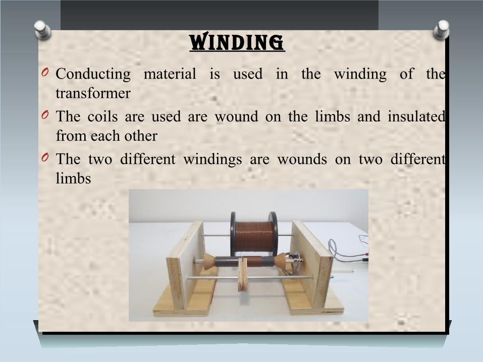
WindingO Conducting material is used in the winding of the
transformer O The coils are used are wound on the limbs and insulated
from each otherO The two different windings are wounds on two different
limbs
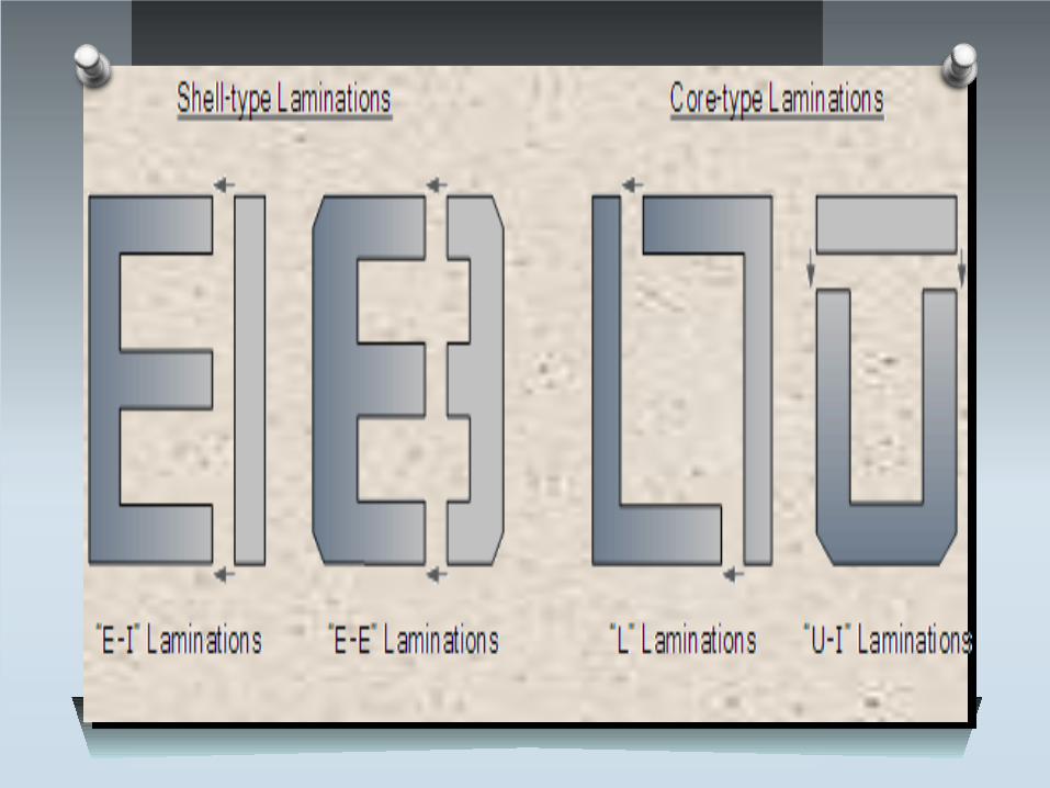
Shell type conStruction O In this type two magnetic circuit are used O The winding is wound on central limbsO For the cell type each high voltage winding lie between
two voltage portion sandwiching the high voltage winding
O Sub division of windings reduces the leakage fluxO Greater the number of sub division lesser the reactance O This type of construction is used for high voltage
loSSeS in tranSformer
O Copper losses : It is due to power wasted in the form of I2Rdue to
resistance of primary and secondary. The magnitude of copper losses depend upon the current flowing through these coils.
O Iron losses : These losses are also called as core losses. There are two types :
1. Hysteresis losses
2. Eddy current losses
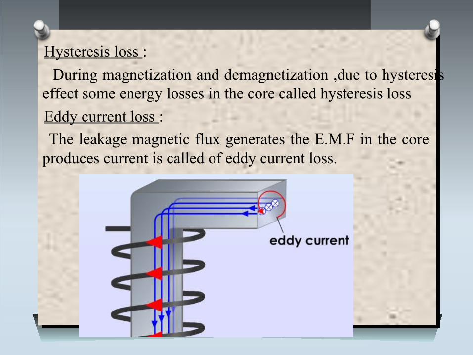
Hysteresis loss :
During magnetization and demagnetization ,due to hysteresis effect some energy losses in the core called hysteresis loss
Eddy current loss :
The leakage magnetic flux generates the E.M.F in the core produces current is called of eddy current loss.
ideal V/S practical tranSformer
O A transformer is said to be ideal if it satisfies the following properties, but no transformer is ideal in practice.
O It has no lossesO Windings resistance are zeroO There is no flux leakage O Small current is required to produce the magnetic field
While the practical transformer has windings resistance , some leakage flux and has lit bit losses
application and uSeSO The transformer used in television and photocopy
machines O The transmission and distribution of alternating power is
possible by transformer O Simple camera flash uses fly back transformer O Signal and audio transformer are used couple in
amplifier
AC MOTORS
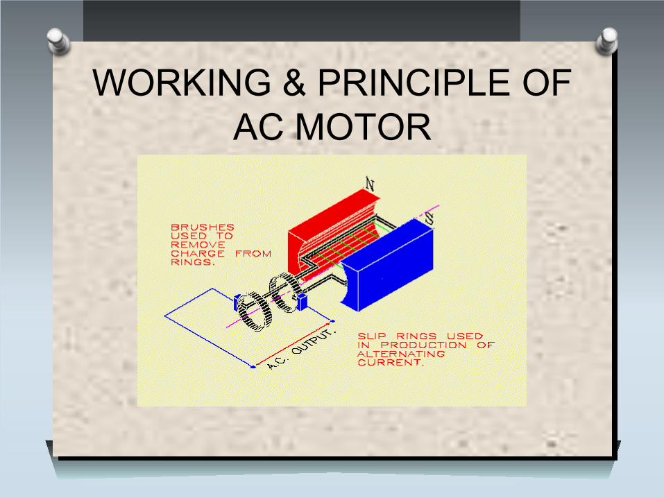
WORKING & PRINCIPLE OF AC MOTOR
TYPES OF AC MOTORS
Based on phases1.Single phase induction motors
2.Three phase induction motors
SINGLE PHASE INDUCTION MOTOR
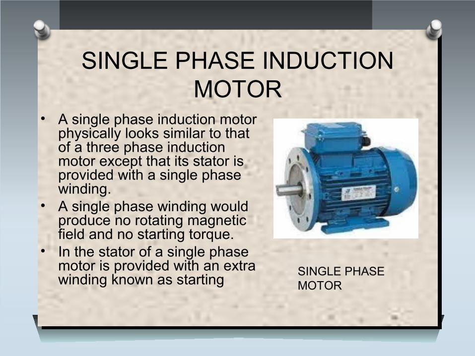
• A single phase induction motor physically looks similar to that of a three phase induction motor except that its stator is provided with a single phase winding.
• A single phase winding would produce no rotating magnetic field and no starting torque.
• In the stator of a single phase motor is provided with an extra winding known as starting
SINGLE PHASE MOTOR
SINGLE PHASE INDUCTION MOTOR
O A single phase induction motor physically looks similar to that of a three phase induction motor except that its stator is provided with a single phase winding.
O The rotor of any single phase induction motor is interchangeable with that of a polyphase induction motor
O A single phase winding would produce no rotating magnetic field and no starting torque.
O In the stator of a single phase motor is provided with an extra winding known as starting
Types of single phase ac motor
O Spilt-phase induction motorO Capacitor start induction motorO Capacitor start and capacitor run induction
motorO Permanent capacitor induction motorO Shaded pole induction motor
SPILT PHASE INDUCTION MOTOR
SPILT PHASE INDUCTION MOTOR
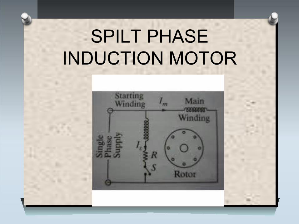
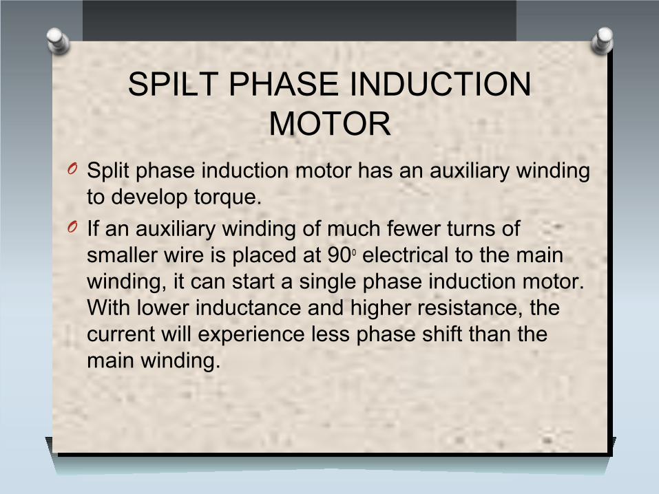
O Split phase induction motor has an auxiliary winding to develop torque.
O If an auxiliary winding of much fewer turns of smaller wire is placed at 90o electrical to the main winding, it can start a single phase induction motor. With lower inductance and higher resistance, the current will experience less phase shift than the main winding.
CAPACITOR START INDUCTION MOTOR
CAPACITOR START INDUCTION MOTOR
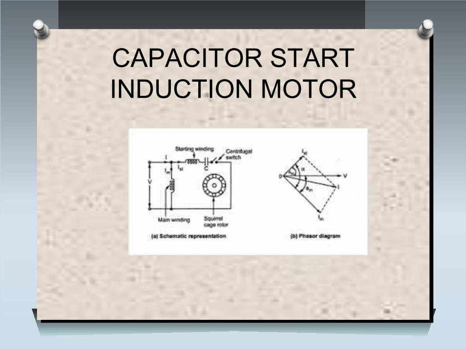
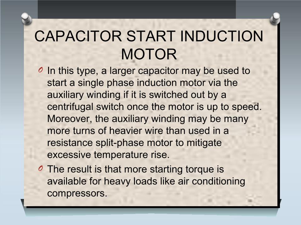
O In this type, a larger capacitor may be used to start a single phase induction motor via the auxiliary winding if it is switched out by a centrifugal switch once the motor is up to speed. Moreover, the auxiliary winding may be many more turns of heavier wire than used in a resistance split-phase motor to mitigate excessive temperature rise.
O The result is that more starting torque is available for heavy loads like air conditioning compressors.
CAPACITOR START AND CAPACITOR RUN INDUCTION
MOTOR
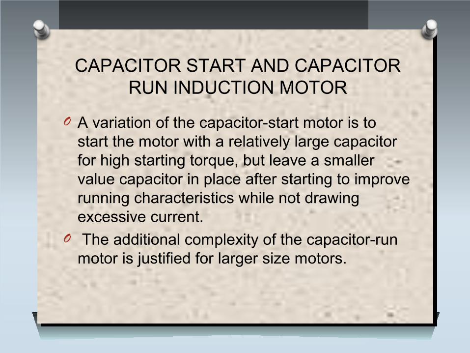
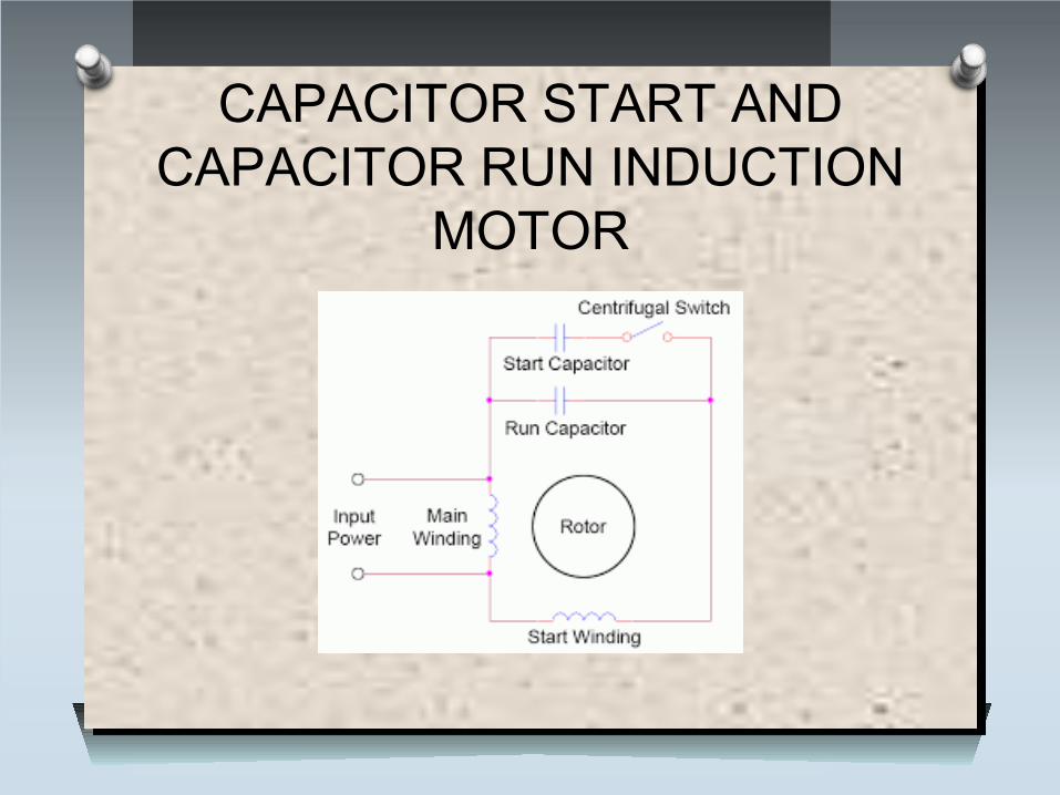
CAPACITOR START AND CAPACITOR RUN INDUCTION MOTOR
O A variation of the capacitor-start motor is to start the motor with a relatively large capacitor for high starting torque, but leave a smaller value capacitor in place after starting to improve running characteristics while not drawing excessive current.
O The additional complexity of the capacitor-run motor is justified for larger size motors.
PERMANENT CAPACITOR INDUCTION MOTOR
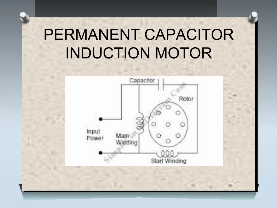
PERMANENT CAPACITOR INDUCTION MOTOR
• One way to solve the single phase problem is to build a 2-phase motor, deriving 2-phase power from single phase.
• This requires a motor with two windings spaced apart 90o electrical, fed with two phases of current displaced 90o in time. This is called a permanent-split capacitor motor.
• This type of motor suffers increased current magnitude and backward time shift as the motor comes up to speed, with torque pulsations at full speed.
SHADED POLE INDUCTION MOTOR
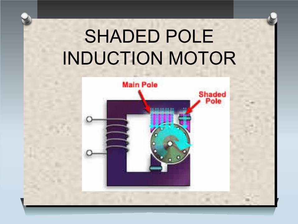
SHADED POLE INDUCTION MOTORO Shaded-pole motors are the original type of AC
single-phase induction motor.O A shaded-pole motor is basically a small
squirrel-cage motor in which the auxiliary winding is composed of a copper ring or bar surrounding a portion of each pole.
O This auxiliary single-turn winding is called a shading coil. O Currents induced in this coil by the magnetic field create a
second electrical phase by delaying the phase of magnetic flux change for that pole enough to provide a 2-phase rotating magnetic field.
O Another method of electrical reversing involves four coils.
THREE PHASE INDUCTION MOTORS
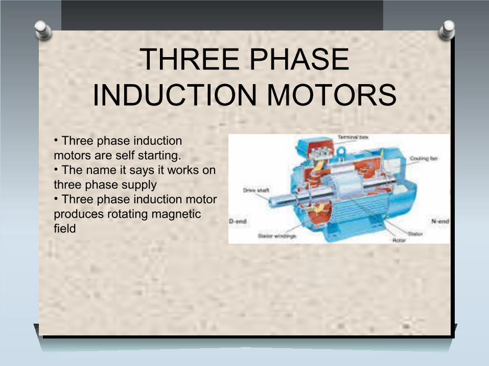
• Three phase induction motors are self starting.• The name it says it works on three phase supply• Three phase induction motor produces rotating magnetic field
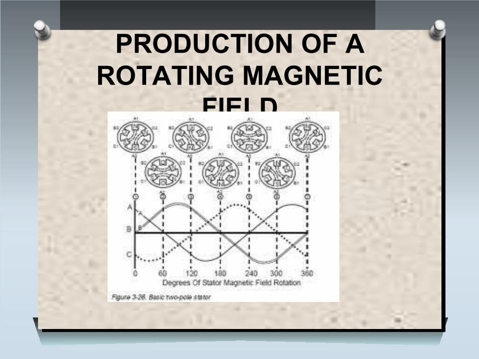
PRODUCTION OF A ROTATING MAGNETIC
FIELD
Types of three phase induction motors
O Squirrel cage induction motor
O Slip ring induction motor
SQUIRREL CAGE INDUCTION MOTOR
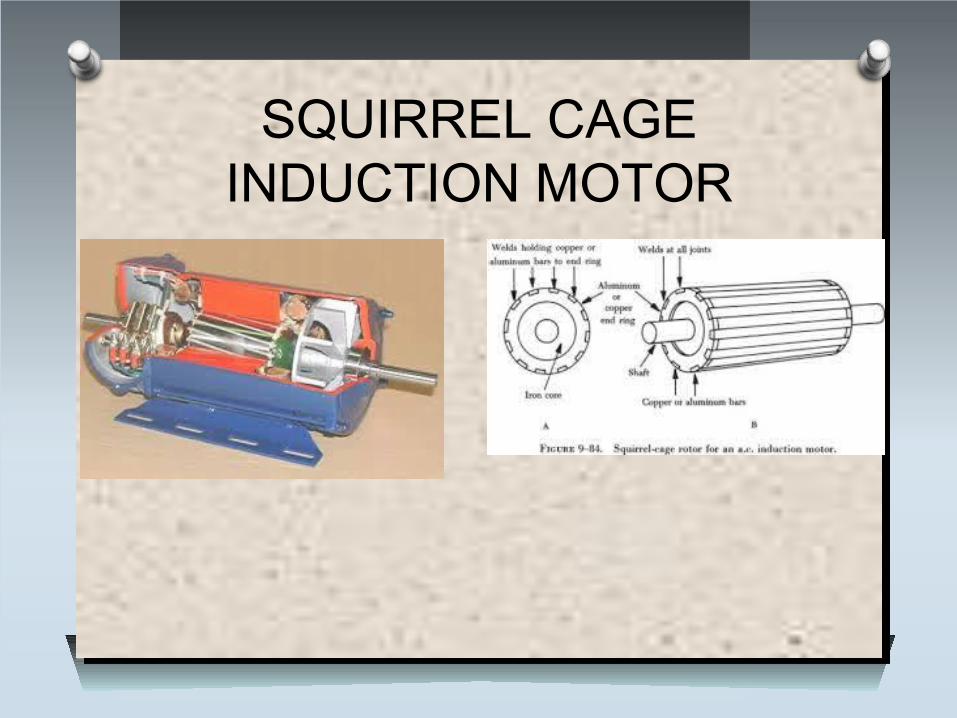
SQUIRREL CAGE INDUCTION MOTOR
O The motor rotor shape is a cylinder mounted on a shaft. Internally it contains longitudinal conductive bars (usually made of aluminum or copper) set into grooves and connected at both ends by shorting rings forming a cage-like shape.
O The name is derived from the similarity between this rings-and-bars winding and a squirrel cage.
O The solid core of the rotor is built with stacks of electrical steel laminations.
O The field windings in the stator of an induction motor set up a rotating magnetic field through the rotor.
O The relative motion between this field and the rotor induces electric current in the conductive bars. In turn these currents lengthwise in the conductors react with the magnetic field of the motor to produce force acting at a tangent orthogonal to the rotor, resulting in torque to turn the shaft.
O The difference in speed is called slip and increases with load.
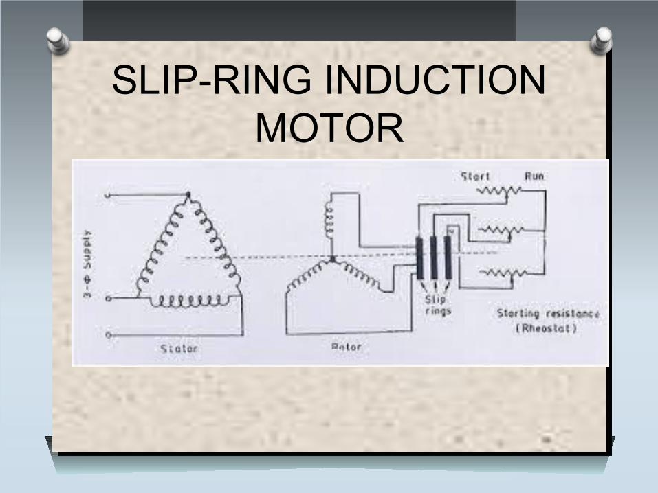
SLIP-RING INDUCTION MOTOR
SLIP-RING INDUCTION MOTORO In this type of three phase induction motor the
rotor is wound for the same number of poles as that of stator but it has less number of slots and has less turns per phase of a heavier conductor.
O The rotor also carries star or delta winding similar to that of stator winding. The rotor consists of numbers of slots and rotor winding are placed inside these slots. The three end terminals are connected together to form star connection. As its name indicates three phase slip ring induction motor consists of slip rings connected on same shaft as that of rotor.
O The three ends of three phase windings are permanently connected to these slip rings. The external resistance can be easily connected through the brushes and slip rings and hence used for speed control and improving the starting torque of three phase induction motor.
O The brushes are used to carry current to and from the rotor winding.
O These brushes are further connected to three phase star connected resistance.
O At starting, the resistance are connected in rotor circuit and is gradually cut out as the rotor pick up its speed.
O When the motor is running the slip ring are shorted by connecting a metal collar, which connect all slip ring together and the brushes are also removed.
O This reduces wear and tear of the brushes.O Due to presence of slip rings and brushes the
rotor construction becomes somewhat complicated therefore it is less used as compare to squirrel cage induction motor.