instructions series type c boilers - direct heating spares · 2017-06-07 · instructions type c...
TRANSCRIPT

Country of destination: GB/IE
Installation andServicingInstructionsType C Boilers
ACO 35 MFFIG.C.N: 47-116-35
LEAVE THESE INSTRUCTIONSWITH THE END USER
SERIES

2
TABLE OF CONTENTS
1. GENERAL INFORMATION1.1. GENERAL INFORMATION 31.2. TECHNICAL INFORMATION 41.3. OVERALL VIEW 6
2. INSTALLATION2.1. REFERENCE STANDARDS 72.2. SITING THE APPLIANCE 72.3. OVERALL DIMENSIONS 82.4. MINIMUM CLEARANCES 82.5. MOUNTING THE APPLIANCE 92.6. ELECTRICAL CONNECTION 92.7. GAS CONNECTION 92.8. WATER CONNECTIONS 102.9. FLUE CONNECTIONS 13
2.9.1 FITTING THE COAXIAL FLUE
(Ø 60 / 100 HORIZONTAL) 142.9.2 FITTING THE 5” FLUE
(Ø 80 / 125 Horizontal/Vertical) 152.9.3 FITTING THE COAXIAL FLUE
(Ø 60 / 100 VERTICAL) 162.9.4 FITTING THE TWIN PIPE (Ø80 / 80) 17
2.10. FITTING THE MECHANICAL/DIGITAL
TIME CLOCK 202.11. SETTING THE MECHANICAL TIME CLOCK 222.11.1. SETTING THE DIGITAL TIME CLOCK 222.12. ACCESSORY CONNECTION 242.13. ELECTRICAL DIAGRAM 262.14. WATER CIRCUIT DIAGRAM 28
3. COMMISSIONING3.1. INITIAL PREPARATION 303.2. REMOVING THE CASING 323.3. CONTROL PANEL 333.4. INITIAL START-UP 353.5. DISPLAY: MESSAGES SHOWN DURING
NORMAL OPERATION 363.6. OPERATING PARAMETERS 37
3.6.1. REGULATION MENU TABLE 373.6.2. SETTINGS DISPLAY 433.6.3. GAS REGULATION CHECK 443.6.4. IGNITION DELAY ADJUSTMENT 453.6.5. ADJUSTING THE MAXIMUM HEATING
POWER 453.6.6. SOFT LIGHT ADJUSTMENT 45
3.7. CHANGING THE TYPE OF GAS 453.8. ADJUSTING THE DOMESTIC HOT
WATER FLOW RATE 453.9. BALANCING THE CENTRAL
HEATING SYSTEM 453.10. BOILER SAFETY SYSTEMS 463.11. COMPLETION 473.12. DRAINING 47
4. ZONE VALVES 48
5. SEQUENCE OF OPERATION 515.1 CENTRAL HEATING MODE 515.2 DOMESTIC HOT WATER MODE 51
6. MAINTENANCE 526.1. GENERAL REMARKS 526.2. CLEANING THE PRIMARY EXCHANGER 526.3. CLEANING THE CONDENSATE TRAP 526.4. OPERATIONAL TEST 52
7. SERVICING INSTRUCTIONS 537.1. REPLACEMENT OF PARTS 537.2. TO GAIN GENERAL ACCESS 537.3. ACCESS TO THE COMBUSTION
CHAMBER 547.3.1. REMOVING THE FAN 547.3.2. REMOVING THE AIR PRESSURE SWITCH 557.3.3. REMOVING THE BURNER 557.3.4. REMOVING THE ELECTRODES 567.3.5. REMOVING THE HEAT EXCHANGER 567.3.6. REMOVING THE CONDENSATE
TRAP (TUBE) 587.3.7. REMOVING THE CONDENSATE TRAP 58
7.4. ACCESS TO THE GAS VALVE 597.4.1. REMOVING THE GAS VALVE 597.4.2. REMOVING THE SPARK GENERATOR 60
7.5. ACCESS TO THE WATER CIRCUIT 607.5.1. REMOVING THE D.H.W.
(SECONDARY) EXCHANGER 607.5.2. REMOVING THE SAFETY VALVE 617.5.3. REMOVING THE AUTOMATIC AIR VENT 617.5.4. REMOVING THE DIVERTER VALVE
ACTUATOR 627.5.5. REMOVING THE DHW FLOW SWITCH
(MFFI ONLY) 627.5.6. REMOVING THE PUMP 627.5.7. REMOVING THE PRESSURE GAUGE 637.5.8. REMOVING THE EXPANSION VESSEL 647.5.9. REMOVING THE D.H.W. TEMPERATURE
PROBE (N.T.C. - MFFI ONLY) 647.5.10. REMOVING THE C.H. FLOW
TEMPERATURE PROBE (N.T.C.) 657.5.11. REMOVING THE C.H. RETURN
TEMPERATURE PROBE (N.T.C.) 657.6. ACCESS TO THE CONTROL SYSTEM 66
7.6.1. CHECKING THE FUSES 667.6.2. REMOVING THE PRINTED CIRCUIT
BOARDS 667.6.3. REMOVING THE TIME CLOCK 67
8. FAULT FINDING 688.1 FAULT FINDING GUIDE
(FLOW-CHARTS) 68
9. SHORT SPARES PARTS LIST 72
10. ANNUAL MAINTENANCE CHECKLIST 76
11. BENCHMARK COMMISSIONING CHECKLIST 78
12. SERVICE INTERVAL RECORD 79
PAGE PAGE

3
This manual is an integral and essential part of the product. Itshould be kept with the appliance so that it can be consulted bythe user and our authorised personnel.
Please carefully read the instructions and notices about the unitcontained in this manual, as they provide important informationregarding the safe installation, use and maintenance of theproduct.
For operating instructions please consult the separate UsersManual.
1. GENERAL INFORMATION
Read the instructions and recommendations in these Installationand Servicing Instructions carefully to ensure proper installation,use and maintenance of the appliance.
Keep this manual in a safe place. You may need it for your ownreference while Servicing Technicians or your installer mayneed to consult it in the future.
The ACO 35 MFFI is a combined appliance for the production ofcentral heating (C.H.) and domestic hot water (D.H.W.) and isdesigned for domestic use only..
This appliance must be used only for the purpose for which it isdesigned.
The manufacturer declines all liability for damage caused byimproper or negligent use.
No asbestos or other hazardous materials have been used inthe fabrication of this product.
MTS recommends the use of protective clothing when installingand working on the appliance i.e. gloves.
Before connecting the appliance, check that the informationshown on the data plate and the table in Section 1.2 (page 4)comply with the electric, water and gas mains of the property.You will find the data plate on the inside of the casing.The gas with which this appliance operates is also shown on thelabel at the bottom of the boiler.
Do not install this appliance in a damp environment or close toequipment which spray water or other liquids.Do not place objects on the appliance.Do not allow children or inexperienced persons to use theappliance without supervision.
If you smell gas in the room, do not turn on or off lightswitches, use the telephone or any other object which mightcause sparks.Open doors and windows immediately to ventilate the room.Shut the gas mains tap (at or adjacent to the gas meter) or thevalve of the gas cylinder and call your Gas Supplier immediately.
Always disconnect the appliance either by unplugging it fromthe mains or turning off the mains switch before cleaning theappliance or carrying out maintenance.
In the case of faults or failure, switch off the appliance andturn off the gas tap. Do not tamper with the appliance.For repairs, call your local Authorised Servicing Agent andrequest the use of original spare parts. For in-guarantee repairscontact MTS (GB) Limited.
1.1. GENERAL INFORMATION

4
NameCE CertificationFlue Type
Heat Input max (Domestic Hot Water) kWHeat Input max/min (Central Heating) kWHeat Output max/min (Central Heating) kWHeat Output max/min (Domestic Hot Water) kWEfficiency of Nominal Heat Input (60/80°C) %Efficiency of Nominal Heat Input (30/50°C) %Efficiency at 30% of Nominal Heat Input (47°C) %Efficiency at 30% of Nominal Heat Input (30°C) %Efficiency at Minimum Input %Efficiency (Dir. 92/42/EEC)** SEDBUK Rating Band / %Heat Loss to the Casing (∆T=50°C) %Flue Heat Loss with Burner Operating %
Gen
eral
Info
En
erg
y P
erfo
rman
ce
Max Discharge of Products of Combustion (G20) Kg/hTemp. of exhaust fumes at nominal capacity °CCO2 Content %O2 Content %CO Content ppmNox Class
Em
issi
on
s
Head Loss on Water Side (max) (∆T=20°C) mbarResidual Head of System barExpansion Vessel Pre-load Pressure barMaximum Heating Pressure barExpansion Vessel Capacity lMaximum Water Content of System lHeating Temperature max/min (High temperature) °CHeating Temperature max/min (Low Temperature) °C
Cen
tral
Hea
ting
Domestic Hot Water Temperature (approx) max/min °CSpecific Flow Rate (10 minutes/∆T 30°C) l/minD.H.W. Flow Rate ∆T=25°C l/minD.H.W. Flow Rate ∆T=35°C l/minD.H.W. Minimum Flow Rate l/minPressure of Domestic Hot Water max/min bar
Dom
estic
Hot
Wat
er
Nominal Pressure Natural Gas (G20) mbarConsumption at Nominal Capacity(G20) m3/hGas Consumption after 10 Minutes* m3G
as
Electrical Supply V/HzPower Consumption WMinimum Ambient Temperature °CProtection Grade of Electrical System IPInternal Fuse RatingE
lect
rical
Dat
a
Weight KgCasing Dimensions (D/W/H) mm
G.C. Number
ACO 35 MFFI1312BQ4461
C13-C33-C43-C53-C83-B23-B33
44.6629.43.8109
5 (70 mg/kW/h)
2000.20.737
13082 / 4675 / 25
56 / 3616
18.8413.52.5
6 / 0.2
203.170.37
34
230/50145+5
24D2A Fast Fuse
43310/450/750
47-116-35
* Calculated at 70% maximum output** Calculated on Upper calorific value
Max. Condensate produced l/hPH of condensate PH
1.2. TECHNICAL INFORMATION
37.233.3 / 7.429.4 / 6.533.3 / 7.4
88.294.692.597.487.3
A / 90.20.41.7
1
2
3
4
5 6
11
7
8
9
10
11 1312 14 15 16
17
18
19
20
21
22
23
24
2526
5
LEGEND:
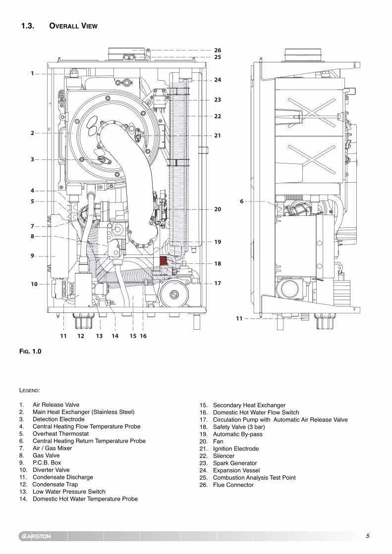
1. Air Release Valve2. Main Heat Exchanger (Stainless Steel)3. Detection Electrode4. Central Heating Flow Temperature Probe5. Overheat Thermostat6. Central Heating Return Temperature Probe7. Air / Gas Mixer8. Gas Valve9. P.C.B. Box10. Diverter Valve11. Condensate Discharge12. Condensate Trap13. Low Water Pressure Switch14. Domestic Hot Water Temperature Probe
1.3. OVERALL VIEW
FIG. 1.0
15. Secondary Heat Exchanger16. Domestic Hot Water Flow Switch17. Circulation Pump with Automatic Air Release Valve18. Safety Valve (3 bar)19. Automatic By-pass20. Fan21. Ignition Electrode 22. Silencer23. Spark Generator24. Expansion Vessel25. Combustion Analysis Test Point26. Flue Connector

6
The technical information and instructions provided herein beloware intended for the installer / Servicing Technician so that theunit may be installed and serviced correctly and safely.
In the United Kingdom the installation and initial start up of theboiler must be by a CORGI Registered Installer in accordancewith the installation standards currently in effect, as well as withany and all local health and safety standards i.e. CORGI.
In the Republic of Ireland the installation and initial start up ofthe appliance must be carried out by a Competent Person inaccordance with the current edition of I.S.813 “Domestic GasInstallations”, the current Building Regulations, reference shouldalso be made to the current ETCI rules for electrical installation.
This appliance must be installed by a competent installer inaccordance with current Gas Safety (installation & use)Regulations.
The installation of this appliance must be in accordance with therelevant requirements of the Local Building Regulations, thecurrent I.E.E. Wiring Regulations, the byelaws of the local waterauthority, in Scotland, in accordance with the Building Standards(Scotland) Regulation and Health and Safety document No. 635“Electricity at work regulations 1989” and in the Republic ofIreland with the current edition of I.S. 813, the Local BuildingRegulations (IE).
C.O.S.H.H.Materials used in the manufacture of this appliance are non-hazardous and no special precautions are required whenservicing.
Installation should also comply with the following BritishStandard Codes of Practice:
and in the Republic of Ireland in accordance with the followingCodes of Practice:
2. INSTALLATION
2.1. REFERENCE STANDARDS
BS 7593:1992 Treatment of water in domestic hot watercentral heating systems
BS 5546:1990 Installation of hot water supplies fordomestic purposes
BS 5440-1:2000 FluesBS 5440-2:2000 Air supplyBS 5449:1990 Forced circulation hot water systemsBS 6798:2000 Installation of gas fired hot water boilers
of rated input not exceeding 70kWBS 6891:2005 Installation of low pressure gas pipe up to
28mmBS 7671:2001 IEE wiring regulationsBS 4814:1990 Specification for expansion vesselsBS 5482:1994 Installation of L.P.G.
I.S. 813 Domestic Gas Installations
2.2. SITING THE APPLIANCE
The appliance may be installed in any room or indoor area,although particular attention is drawn to the requirements of thecurrent I.E.E. Wiring Regulations, and in Scotland, the electricalprovisions of the Building Regulations applicable in Scotland,with respect to the installation of the combined appliance in aroom containing a bath or shower, the location of the boiler in aroom containing a bath or shower should only be considered ifthere is no alternative.
Where a room-sealed appliance is installed in a roomcontaining a bath or shower the appliance and anyelectrical switch or appliance control, utilising mainselectricity should be situated so that it cannot be touchedby a person using the bath or shower, specifically inaccordance with current IEE Wiring Regulations.
The location must permit adequate space for servicing and aircirculation around the appliance as indicated in Section 2.4.The location must permit the provision of an adequate flue andtermination.For unusual locations special procedures may be necessary.BS 6798-2000 gives detailed guidance on this aspect.A compartment used to enclose the appliance must be designedspecifically for this purpose. No specific ventilation requirementsare needed for the installation within a cupboard.This appliance is not suitable for outdoor installation.
The type C appliances (in which the combustion circuit, airvent intake and combustion chamber are air-tight withrespect to the room in which the appliance is installed) canbe installed in any type of room.
Secondary ventilation is not required with this boiler. The boilermust be installed on a solid, non-combustible, permanent wall toprevent access from the rear.

7
2.3. OVERALL DIMENSIONS
In order to allow access to the interior of the boiler for maintenancepurposes, the boiler must be installed in compliance with theclearance requirements indicated in the diagram below.
2.4. MINIMUM CLEARANCES
LEGEND:
A = Central Heating Flow (3/4”) (22mm Copper Tail)B = Domestic Hot Water Outlet (1/2”) (15 mm Copper Tail)C = Gas Inlet (3/4”) ( 22mm Copper Tail)D = Domestic Cold Water Inlet (1/2”) (15mm Copper Tail)E = Central Heating Return (3/4”) (22mm Copper Tail)SV outlet = 1/2” Female BSP (Not Shown)
785310 450FIG. 2.0
93 65
450
67 67 65 93
143
100120
750
355
45 50watergas
310
323
225 225
130 130
F
FIG. 2.1
FIG. 2.2
After removing the boiler from its packaging, remove thetemplate from the separate box containing the connection kit.NOTE: Pay particular attention to any test water that may spillfrom the appliance.
Place the template in the position the appliance is to bemounted and after ensuring it is hanging squarely, use it to markthe holes for the hanging bracket, connection kit and flue pipe(s)NB: For further information relating to the flue installation pleaserefer to Section 2.9 FLUE CONNECTION. (If the appliance is to befitted on a wall of combustible material, the wall must beprotected by a sheet of fireproof material).If the appliance is to be fitted into a timber framed building,guidance should be sought from the Institute of Gas Engineersdocument REF: IGE/UP/7.
2.5.1. Drill the wall and plug using those supplied with theconnections kit, position the hanging bracket andsecure with the wall screws supplied, assemble theconnection kit and secure to the wall. NOTE: It is highlyrecommended that a spirit level be used to position theappliance to ensure that it is perfectly level.
2.5.2. Position the appliance on the hanging bracket andconnect the connection kit to the boiler connections.(see also Sections 2.7 Gas Connections, 2.8 WaterConnections & FIG. 2.4).
For safety purposes, have a competent person carefully checkthe electrical system in the property, as the manufacturer will notbe held liable for damage caused by the failure to earth theappliance properly or by anomalies in the supply of power. Makesure that the residential electrical system is adequate for themaximum power absorbed by the unit, which is indicated on therating plate. In addition, check that the section of cabling isappropriate for the power absorbed by the boiler.
2.5. MOUNTING THE APPLIANCE

8
2.8. WATER CONNECTIONS
Legend:
A = Central Heating FlowB = Domestic Hot Water OutletC = Gas InletD = Domestic Cold Water InletE = Central Heating ReturnH = Condensate dischargeG = Condensate trapF = Safety valve discharge
Central HeatingDetailed recommendations are given in BS 6798:2000 and BS5449-1:1990, the following notes are given for general guidance.PIPE WORK:
Copper tubing to BS EN 1057:1996 is recommended forwater pipes. Jointing should be either with capillary solderedor compression fittings.Where possible pipes should have a gradient to ensure air iscarried naturally to air release points and water flowsnaturally to drain taps.The appliance has a built-in automatic air release valve, howeverit should be ensured as far as possible that the appliance heatexchanger is not a natural collecting point for air.Except where providing useful heat, pipes should beinsulated to prevent heat loss and avoid freezing.Particular attention should be paid to pipes passing throughventilated spaces in roofs and under floors.
BY-PASS:The appliance includes an automatic by-pass valve, whichprotects the main heat exchanger in case of reduced orinterrupted water circulation through the heating system, dueto the closing of thermostatic valves or cock-type valveswithin the system.
SYSTEM DESIGN:This boiler is suitable only for sealed systems.
DRAIN COCKS:These must be located in accessible positions to permit thedraining of the whole system. The taps must be at least15mm nominal size and manufactured in accordance with BS2870:1980.
VIEW OF THE BOILER CONNECTIONS
G
H
FIG. 2.4
2.6. ELECTRICAL CONNECTION
The boiler operates with alternating current, as indicated in thetechnical data table (Section 1.2), where the maximum absorbedpower is also indicated. Make sure that the connections for theneutral and live wires correspond to those indicated in Fig.2.3).The appliance electrical connections are situated inside theelectrical box (see Section 2.12).IMPORTANT!In the event that the power supply cable must be changed,replace it with one with the same specifications. Make theconnections to the terminal board located within the controlpanel, as follows:- The yellow-green wire should be connected to the terminal
marked with the earth symbol; make sure to re-use the ferrulemounted on the other supply cable;
- The blue wire should be connected to the terminal marked “N”;- The brown wire should be connected to the terminal marked “L”.
FIG. 2.3
2.7. GAS CONNECTION
The local gas region contractor connects the gas meter to theservice pipe.If the gas supply for the boiler serves other appliances ensurethat an adequate supply is available both to the boiler and theother appliances when they are in use at the same time.Pipe work must be of an adequate size. Pipes of a smaller sizethan the boiler inlet connection must not be used.
Note: The diagrams for the electrical system are indicated inSections 2.12 and 2.13 (pages 22-24).
Warning, this appliance must be earthed.
External wiring to the appliance must be carried out by acompetent person and be in accordance with the current I.E.E.Regulations and applicable local regulations.The appliance is supplied with a fly-lead already connected, thismust be connected to a 240v supply fused at 3A and mustfacilitate complete electrical isolation of the appliance, by theuse of a fused double pole isolator having a contact separationof at least 3 mm in all poles or alternatively, by means of a 3 Afused three pin plug and unswitched shuttered socket outlet bothcomplying with BS 1363.The point of connection to the Electricity supply must be readilyaccessible and adjacent to the appliance unless the appliance isinstalled in a bathroom when this must be sited outside thebathroom (see Section 2.2).Should external controls be required, the design of the externalelectrical circuits should be undertaken by a competent person,see Sections 2.12 for further information.
F

9
0
100
200
300
400
500
600
700
800
0 200 400 600 800 1000 1200 1400 1600
[l/h]
[mb
ar]
RESIDUAL HEAD OF THE BOILER ∆T20°C
FIG. 2.5
SAFETY VALVE DISCHARGE:The discharge should terminate facing downwards on theexterior of the building in a position where discharging(possibly boiling water & steam) will not create danger ornuisance, but in an easily visible position, and not causedamage to electrical components and wiring.The discharge must not be over an entrance or a window orany other type of public access.
CONDENSATE DISCHARGE:A flexible hose is supplied for connection to the condensatedischarge point H (Fig. 2.4). The condensate discharge hosefrom the boiler must have a continuous fall of 2.5° and mustbe inserted by at least 50 mm into a suitable acid resistanttundish / pipe - e.g. plastic waste or overflow pipe. Thecondensate discharge pipe must have a continuous fall andpreferably be installed and terminated within the building toprevent freezing.
NOTE: THE FLEXIBLE CONDENSE HOSE SUPPLIED WITH THE
APPLIANCE CAN BE EXTENDED BY PULLING THE TUBE OPENING THE
RIBBED PIPE.
The discharge pipe must be terminated in a suitable position:i) Connecting in to an internal soil stack (at least 450 mm
above the invert of the stack). A trap giving a water seal ofat least 75 mm must be incorporated into the pipe run,there also must be an air break upstream of the trap.
ii) Connecting into the waste system of the building such asa washing machine or sink trap. The connection must beupstream of the washing machine/sink (If the connectionis down stream of the waste trap then an additional trapgiving a minimum water seal of 75 mm and an air breakmust be incorporated in the pipe run, as above.
iii) Terminating into a gully, below the grid level but above thewater level.
iv) Into a soakway.
NOTE: If any condensate pipe work is to be installed externally,then it should be kept to a minimum and be insulated with awaterproof insulation and have a continuous fall.
Some examples of the type of condensate drains can beseen on this page.
2. External termination of condensate drainage pipe viainternal discharge branch (e.g. sink waste) and condensatesiphon
3. External termination of condensate drainage pipe via internal discharge branch (e.g. sink waste - proprietary fitting).
1. Internal termination of condensate drainage pipe to internal stack

10
4. External termination of condensate drainage pipe viacondensate siphon
AIR RELEASE POINTS:These must be fitted at all high points where air naturallycollects and must be sited to facilitate complete filling of thesystem.The appliance has an integral sealed expansion vessel toaccommodate the increase of water value when the system isheated.It can accept up to 7 l (1.5 gal) of expansion water. If theheating circuit has an unusually high water content, calculatethe total expansion and add an additional sealed expansionvessel with adequate capacity.
MAINS WATER FEED - CENTRAL HEATING:There must be no direct connection to the mains water supplyeven through a non-return valve, without the approval of theLocal Water Authority.
FILLING:A method for initially filling the heating system is supplied withthe connection kit. The filling loop is connected between thecold water inlet and the central heating flow connections, andincorporates a non-return valve. To operate the filling loop, itis necessary to open both quarter turn handles, once therequired pressure has been achieved, close both handlesand disconnect the hose in accordance with waterregulations. NOTE: The installer should ensure that there areno leaks as frequent filling of the heating system can lead topremature scaling of the main exchanger and failure ofhydraulic components.
DOMESTIC WATER
The domestic water must be in accordance with the relevantrecommendation of BS 5546:1990. Copper tubing to BS EN1057:1996 is recommended for water carrying pipe work andmust be used for pipe work carrying drinking water, a scalereducer should also be used to reduce the risk of scaleforming in the domestic side of the heat exchanger.
UNDER FLOOR HEATING SYSTEMS:In the event of an under floor heating system, fit a safetythermostat on the boiler flow (instructions for wiring thethermostat to connection SP on the PCB can be found inSection 2.12). This thermostat should be positioned at a safedistance from the boiler to ensure the correct operation of thesame. If the thermostat is positioned too close to the boiler, thewater remaining in the boiler after domestic hot water has beendrawn will flow into the central heating system and may causethe thermostat contact to open without there being any realdanger of the system being damaged, this would lead to aboiler shutdown both in D.H.W. mode and C.H. mode, and theerror code “E08” would be displayed; boiler operation resumesautomatically when the thermostat contact closes on cooling. Should the thermostat fail to be installed as recommended, theunder floor heating system can be protected by installing athermostatic valve upstream from the thermostat in order toprevent the flow of excessively hot water towards the system.
WATER TREATMENT
The boiler is equipped with a stainless steel heat exchanger.
The detailed recommendations for water treatment are givenin BS 7593:1992 (Treatment of water in domestic hot watercentral heating systems); the following notes are given forgeneral guidance;
If the boiler is installed on an existing system, anyunsuitable additives must be removed.
Under no circumstances should the boiler be fired before thesystem has been thoroughly flushed; the flushing proceduremust be in line with BS7593:1992.
We highly recommend the use of a flushing detergentappropriate for the metals used in the circuit. These includecleansers produced by Fernox and BetzDearborn, whose

11
function is to dissolve any foreign matter that may be in thesystem;
In hard water areas or where large quantities of water are inthe system the treatment of the water to prevent prematurescaling of the main heat exchanger is necessary.
The formation of scale strongly compromises the efficiency ofthe thermic exchange because small areas of scale cause ahigh increase of the temperature of the metallic walls andtherefore add to the thermal stress of the heat exchanger.
Demineralised water is more aggressive so in this situation itis necessary to treat the water with an appropriate corrosioninhibitor.
Any treatment of water by additives in the system for frostprotection or for corrosion inhibition has to be absolutelysuitable for all the metals used in the circuit.
The use of a corrosion inhibitor in the system such as FernoxMB-1, BetzDeaborn Sentinel X100 or Fernox System Inhibitoris recommended to prevent corrosion (sludge) damaging theboiler and system;
If anti-freeze substances are to be used in the system, checkcarefully that they are compatible with the metals used in thecircuit.
MTS suggests the use of suitable anti-freeze products suchas Fernox ALPHI 11, which will prevent rust and incrustationtaking place.
Periodically check the pH of the water/anti-freeze mixture ofthe boiler circuit and replace it when the amount measured isout of the range stipulated by the manufacturer ( 7 < pH < 8). DO NOT MIX DIFFERENT TYPES OF ANTI-FREEZE
In under-floor systems, the use of plastic pipes withoutprotection against penetration of oxygen through the wallscan cause corrosion of the systems metal parts (metal piping, boiler, etc), through the formation of oxides andbacterial agents.
To prevent this problem, it is necessary to use pipes with an“oxygen-proof barrier”, in accordance with standards DIN4726/4729. If pipes of this kind are not used, keep thesystem separate by installing heat exchangers of thosewith a specific system water treatment.
IMPORTANT Failure to carry out the water treatment procedurewill invalidate the appliance warranty.

12
EE
2.9. CONNECTING THE FLUE
IMPORTANT!!BEFORE CONNECTING THE FLUE, ENSURE THAT 1 LITRE OF
WATER HAS BEEN POURED INTO THE EXHAUST CONNECTION
TO FILL THE CONDENSATE TRAP (FIG.2.7). SHOULD THE TRAP
BE EMPTY THERE IS A TEMPORARY RISK OF FLUE GASSES
ESCAPING INTO THE ROOM.
FIG. 2.7
120
mm
4
Ø 60/100 mm
Fig. 2.9
FIG. 2.9
TERMINAL POSITION mm
A - Directly below an open window or other opening 300B - Below gutters, solid pipes or drain pipes 75C - Below eaves 200D - From vertical drain pipes and soil pipes 75E - From internal or external corners 300F - Above ground on a public walkway or patio 2100G - From a surface facing a terminal 2500H - From a terminal facing a terminal 2500I - Vertically from a terminal in the same wall 1500J - Horizontally from a terminal in the same wall 300K - Horizontally from an opening window 300L - Fixed by vertical flue terminal
FLUE SYSTEM
The provision for satisfactory flue termination must be madeas described in BS 5440-1.The appliance must be installed so that the flue terminal isexposed to outdoor air.The terminal must not discharge into another room or spacesuch as an outhouse or lean-to.It is important that the position of the terminal allows a freepassage of air across it at all times.The terminal should be located with due regard for thedamage or discolouration that might occur on buildings in thevicinity, it must also be located in a place not likely to causenuisance.In cold or humid weather water vapour may condense onleaving the flue terminal.The effect of such “steaming” must be considered.If the terminal is 2.1 metres above a balcony, above groundor above a flat roof to which people have access, then asuitable stainless steel terminal guard must be fitted.
The minimum acceptable spacing from the terminal toobstructions and ventilation openings are specified in Fig.2.9.

13
WarningThe exhaust gas ducts must not be in contact with or close toinflammable material and must not pass through buildingstructures or walls made of inflammable material.When replacing an old appliance, the flue system must bechanged.
ImportantEnsure that the flue is not blocked.Ensure that the flue is supported andassembled in accordance with theseinstructions.
2.9.1 FITTING THE COAXIAL FLUE(Ø 60 / 100 HORIZONTAL)
150 mm�
* slope 5 mm per metre
150 mm
* slope
Installation without extension
Installation with extension
Fig. 2.10
Fig. 2.11
120
Level
Level
CONTENTS:1X SILICONE O-RING (60mm)1X ELBOW (90O)2X WALL SEALS (INTERNAL & EXTERNAL)1X FLUE PIPE INCLUDING TERMINAL (1 METRE - 60/100)1X FLUE CLAMP
1X SCREWS
1x SealOnce the boiler has been positioned on the wall, insert theelbow into the socket and rotate to the required position.NOTE: It is possible to rotate the elbow 360o on its vertical axis.
Using the flue clamp, seals and screws supplied (Fig 2.12)secure the elbow to the boiler.
The 1 metre horizontal flue kit (3318073) supplied is suitablefor an exact X dimension of 815mm.
Measure the distance from the face of the external wall to theface of the flue elbow (X - Fig 2.9), this figure must now besubtracted from 815mm, you now have the total amount to becut from the plain end of the flue.
Draw a circle around the outer flue and cut the flue to therequired length taking care not to cut the inner flue, next cutthe inner flue ensuring that the length between the inner andouter flue is maintained. (Fig 2.12). e.g.
X = 555mm 815-555 = 260mm (Length to be cut from the plain end ofthe flue).
Once cut to the required length, ensure that the flue is freefrom burrs and reassemble the flue. If fitting the flue frominside of the building attach the grey outer wall seal to theflue terminal and push the flue through the hole, once the wallseal has passed through the hole, pull the flue back until theseal is flush with the wall. Alternatively, the flue can beinstalled from outside of the building, the grey outer sealbeing fitted last.

14
Fig. 2.12
2.9.2 FITTING THE 5” FLUE(Ø 80 / 125 HORIZONTAL/VERTICAL)
Should the flue require extending, the flue connections arepush fit, however, one flue bracket should be used to secureeach metre of flue.
NOTE: SEE PAGE 19 FOR MAXIMUM AND MINIMUM FLUE RUNS.
Once the boiler has been positioned on the wall, it isnecessary to insert the Ø80/125 adaptor (FIG. 2.13) for bothhorizontal and vertical flue runs into the boiler flue socket (notsupplied with flue kit - Part No 3318095).
Push the adaptor onto the boilers flue connection, grease theseals then add extensions or elbows as required, secure theadaptor, using the clamp and screws provided.
To fit extensions or elbows it is first necessary to ensure thatthe lip seal is fitted correctly into the inner flue, once verified,it is simply necessary to push them together, no clamps arenecessary to secure the flue components.
Before proceeding to fit the flue, ensure that the maximumflue length has not been exceeded (See the tables on Page19) and that all elbows and bends have been taken intoconsideration, the maximum flue length is 10 metres, for eachadditional 90o elbow 1 metre must be subtracted from thetotal flue length, and for each 45o 0.5 metres must besubtracted from the total flue length (the height of thevertical adaptor and a 45o bend can be seen in Fig. 2.14and a 90o bend in Fig. 2.15).
NOTE: DO NOT CUT THE VERTICAL FLUE KIT.
Screws
Clamp
Seal
Fig. 2.13
Fig. 2.14 Fig. 2.15

15
NOTE: SEE PAGE 19 FOR MAXIMUM AND MINIMUM FLUE RUNS.
CONTENTS:1X SILICONE O-RING (60mm)1X CONICAL ADAPTOR (60/100mm)1X VERTICAL FLUE KIT (80/125mm)3X SCREWS
The vertical flue kit is supplied with a specially designedweather proof terminal fitted, it can be used either with a flatroof or a pitched roof.
The Vertical flue kits useable lengths with the pitched roofflashings are indicated in Fig. 2.16.
Before proceeding to fit the flue, ensure that the maximumflue length has not been exceeded (See the tables on Page19) and that all elbows and bends have been taken intoconsideration, the maximum flue length is 4 metres, for eachadditional 90o elbow 1 metre must be subtracted from thetotal flue length, and for each 45o 0.5 metres must besubtracted from the total flue length (the height of thevertical adaptor and a 45o bend can be seen in Fig. 2.17).
Mark the position of the flue hole in the ceiling and/or roof(see Fig. 2.15 for distance from wall to the centre of the flue).
Cut a 120mm diameter hole through the ceiling and/or roofand fit the flashing plate to the roof.
DO NOT cut the vertical flue kit.
To connect the vertical flue kit directly to the boiler, place thevertical starter kit (Part No. 3318079) (see Fig. 2.16) onto theexhaust manifold and secure with the clamp, fit the verticaladaptor onto the vertical starter kit (note: there is no need touse a clamp to secure this as it is a push fit connection), thevertical flue kit must then be inserted through the roofflashing, this will ensure that the correct clearance above theroof is provided as the terminal is a fixed height.
Should extensions be required, they are available in 1 metre(Part No. 3318077), 500mm (Part No. 3318078) and 160mmlengths, they must be connected directly to the vertical starterkit before connecting the adaptor to allow the vertical flue kitto be fitted. In the event that extension pieces need to beshortened, they must only be cut at the male end and it mustbe ensured that the inner and outer flue remain flush (Fig.2.12)
When utilising the vertical flue system, action must be takento ensure that the flue is supported adequately to prevent theweight being transferred to the appliance flue connection byusing 1 flue bracket per extension.
When the flue passes through a ceiling or wooden floor, theremust be an air gap of 25mm between any part of the fluesystem and any combustible material. The use of a ceilingplate will facilitate this. Also when the flue passes from oneroom to another a fire stop must be fitted to prevent thepassage of smoke or fire, irrespective of the structuralmaterial through which the flue passes.
2.9.3. FITTING THE COAXIAL FLUE(Ø 60 / 100 VERTICAL)
Fig. 2.16
Fig. 2.17

16
2.9.4. FITTING THE TWIN PIPE (Ø80 / 80) NOTE: SEE PAGE 19 FOR MAXIMUM AND MINIMUM FLUE RUNS.
Where it is not possible to terminate the flue within thedistance permitted for coaxial flues, the twin flue pipe can beused by fitting a special adaptor to the flue connector andusing the aperture for the air intake located on top of thecombustion chamber.
Always ensure that the flue is adequately supported, usingone flue bracket per extension and avoiding low points. (MTSsupply suitable clamps as Part No. 705778).To utilise the air intake it is necessary to:
1) Take the air intake cover off the top of the appliance2) Assemble the flange on the header supplied with the boiler3) Insert the header on the tube or the elbow up until thelower stop (you do not have to use the washer).4) Insert the elbow/header in the boiler air intake hole and fasten it with screws.
The twin flue pipes can be fitted with or without additionalelbows and need no clamps, simply ensure that the red o-ringis inserted in the female end of the flue pipe and push theextension piece fully into the previous section of flue pipe orelbow, check that the o-ring is not dislodged whenassembling the flue (greasing the seal will aid assembly).
Twin pipe can also be converted back to Coaxial flue toenable vertical termination with a coaxial kit by using the pipebridge (Twin - Coaxial Adaptor - Part No. 3318089). Whenrunning the twin flue pipe vertically.
It is not possible to terminate concentrically horizontally.Termination is only possible with separate air and exhaustterminals.
When siting the twin flue pipe, the air intake and exhaustterminals must terminate on the same wall, the centres of theterminals must be a minimum of 280 mm apart and the airintake must not be sited above the exhaust terminal (refer toFig. 2.20). The air intake pipe can be run horizontally,however, the terminal and the final 1 metre of flue must beinstalled either horizontally or with a slight fall away from theboiler to avoid rain ingress.
It is also strongly recommended that the air intake pipe runbe constructed of insulated pipe to prevent condense formingon the outside of the tube.
The maximum permissible flue length for twin flue isdependent on the type of run used.For flue runs with the intake and exhaust pipes under thesame atmospheric conditions (TYPE 4) the maximum length is38 metres (27kW) and 48 metres (32kW), for runs with theterminals under different atmospheric conditions (TYPE 5) theexhaust terminal must extend 0.5 metres above the ridge ofthe roof (this is not obligatory if the exhaust and air intakepipes are located on the same side of the building). For TYPE
5 also, the maximum permissible combined length is 51metres (27kW) and 49 metres (32kW).
The maximum length is reached by combining the totallengths of both the air intake and exhaust pipes. Therefore amaximum length of 40 metres for example, will allow a fluerun of 20 metres for the air intake and 20 metres for theexhaust pipes, also for each 90
oelbow 2.2 metres must be
subtracted from the total length and for each 45o elbow 1.4metres must be subtracted from the total flue length.
Some of the acceptable flue configurations are detailed onpage 20.
For further information relating to flue runs not illustrated,please contact the Technical Department on 0870 241 8180.

17
Fig. 2.18
ø 1
00
60 mm
In the event that twin flue pipes are used, and the boiler hasa side clearance of less than 60mm from the wall, it isnecessary to cut a larger diameter hole for the flue pipe, thisshould be ø10 cm, this will then allow for easier assembly ofthe air intake elbow and the tube outside the wall (see Fig.2.19).
Fig. 2.19
In the event that the air intake and exhaust are run to the left,it will be necessary to reduce the height of the air intake bycutting 20mm from the base of the air intake elbow (see Fig.2.18)
CoaxialSystems
Twin PipeSystems
Exhaust Type
Type 1Type 1
Types 2 & 3
Type 4
Type 5
Maximum ExtensionExhaust/Air
(m)
4 (Horizontal)16 (Horizontal)
4 (Vertical)16 (Vertical)
54(Air Intake & Exhaust
Equal Lengths (27and 27 metres)
1+56 (Air Intake 1Metre and Exhaust 56
Metres)
Diameter of Pipes
(mm)
Ø 60/100Ø 80/125
Ø 60/100Ø 80/125
Ø 80/80
Ø 80/80
Reduction45o (m)
0.50.5
0.50.5
0.25
0.25
Reduction90o (m)
11
11
0.5
0.5

18
EXHAUST
AIR INTAKE
AIR INTAKE
AIR INTAKE MUST NOT BEFITTED ABOVE THE EXHAUST
Fig. 2.20
NOTE: DRAWINGS ARE INDICATIVE OF FLUEING OPTIONS ONLY.
TYPE 1
TYPE 5TYPE 4
TYPE 3TYPE 2
Fig. 2.19

19
FIG. 2.22
FIG. 2.21
3 2 1
G B R
5 4 3 2 1
G B R
FIG. 2.23
DIGITAL MECHANICAL
FIG. 2.20
C2
C2
C2
2.10. FITTING THE MECHANICAL / DIGITAL
CLOCKThe ACO MFFI boiler is supplied with a factory fittedmechanical time clock. There is a digital clock available asan optional extra (code: 706348).
To fit the digital clock it is necessary to proceed as follows:-
1. Remove the outer casing
2. Open the control panel (see fig. 2.20);
3. Unplug the electrical connection from the PCB and unscrewthe four screws (Fig. 2.21);
4. Remove the time clock (Fig. 2.22).
5. Connect the wires supplied with the clock to the digital timeclock as shown in Fig. 2.23;
6. Reassemble in reverse order.
NOTE: THE MECHANICAL CLOCK HAS FOUR WIRES, THEREFORE THE
HARNESS WILL REQUIRE CHANGING ALSO.

20
2.11. SETTING THE MECHANICAL TIME CLOCK
2.11.1. SETTING THE DIGITALTIME CLOCK
Fig. 2.24
1. General layoutThe mechanical clock covers a 24 hour period. Each tappetrepresents 15 minutes A (Fig. 2.25). An override switch islocated on the clock B (Fig 2.25).
2. To set the timeTo set the time of day, grasp the outer edge of the dial andturn slowly clockwise until the correct time is lined up with thearrow C (Fig. 2.25).
3. To Set the "On" and "Off" timesThe clock uses a 24hours system. e.g. 8 = 8.00 am and 18 = 6.00 pm. "ON" periods are set by sliding all tappetsbetween the "ON" time and the "OFF" time to the outer edgeof the dial.The tappets remaining at the centre of the dial arethe "OFF" periods.
4. For operation
Put the selector switch B to the symbol to control thecentral heating by the clock. Put the switch B to «I» to selectpermanent operation or to «0» to turn the central heating offpermanently.
112233
44
5566
7788
99
1010
11111212 1313 1414
1515
1616
17171818
19192020
2121
22222323
2424
99
66
1212
I
A
C
B
Fig. 2.25
Operating the time switchThe steps marked with the symbol “ ” are necessary to carryout a switching program.
Preparing for OperationActivate the “Res” switch (=RESET) to reset the time switchto its default setting (activate using a pencil or similarpointed instrument). Do this:- every time you wish to “reset” the time switch- to erase all switching times and the current time of day.After approximately two seconds the following displayappears: “– – : – –”.
Enter current time and weekday- Keep the “ ” key pressed downDuring the summer time period press the +/- 1h key once.Enter the hour using the “h” keyEnter the minutes using the “m” keyEnter the day using the “Day” key1 = “Monday”..............7 = Sunday- Release the “ ” key.

21
Entering the switching timesYou have 20 memory Iocations available. Each switchingtime takes up one memory location.Keep pressing the “Prog” key until a free memory location isshown in the display “– –:– –”.Programme ON or OFF with the “ ” key:“ ”= OFF; “ ”= ONEnter the hour using “h”Enter the minutes using “m”If a switching command is to be carried out every day (1 2 34 5 6 7) then store using the “ ” key, otherwise select theday(s) it is to be carried out by using the “Day” key.When the day seIection is left bIank, the programmedswitching instruction operates at the same time every day1 2 3 4 5 6 = Monday – Saturday1 2 3 4 5 = Monday – Friday6 7 =Saturday – Sunday
Selection of single days: 1 = Mon. .............. 2 =Tues.Save the switching time with the “ ” key.The time switch enters the automatic operating mode anddisplays the current time of day.Begin any further entry of a switching time with the “Prog”switch. If your entry is incomplete, the segments not yetselected will blink in the display. After programming iscompleted, and you return the time clock to the current timedisplay with the “ ” key, the time clock will not activate anyswitching instruction required for the current time. You mayneed to manually select the desired switching state with the“ ” key. Thereafter, as the unit encounters furtherswitching instructions in the memory in real time, it willcorrectly activate all subsequent switching instructions.
Manual Override Switch “ ”With the “ ” you can change the current setting at any time.The switching program already entered is not altered.
Reading the programmed switching timesPressing the “Prog” key displays the programmed switchingtimes until the first free memory location appears in the display“– – : – –”.
If you now press the “Prog” key once again, the number of freememory Iocations will be displayed, e.g. “18”. If all memorylocations are occupied, the display “00” appears.
Changing the programmed switching timesPress the “Prog” key repeatedly until the switching time youwant to change is displayed. You can now enter the new data.See point “Entering the switching times”.
Notes on storing switching times:If you end your entry of the switching times by pressing the“Prog” key, then the switching time you have entered will bestored and the next memory location displayed.
In addit ion, a complete switching command is storedautomatically after around 90 seconds provided no other keyis pressed. The time switch then enters the automatic operatingmode and displays the current time again.Deleting individual switching timesPress the “Prog” key repeatedly until the switching time you wishto delete is shown in the display. Then set to “– –” using the “h”or “m” key and keep the “ ” key pressed down for around 3seconds. The switching time is now erased and the current timeis displayed.
AM / PM time display If you press the “+/-1h” and “h” keys at the same time, the timedisplay switches into the AM/PM mode.
22
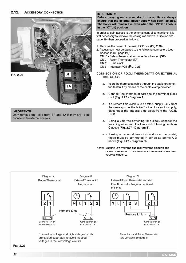
2.12. ACCESSORY CONNECTION IMPORTANT!!Before carrying out any repairs to the appliance alwaysensure that the external power supply has been isolated.The boiler will remain live even when the ON/OFF knob isin the “O”(off) position.
IMPORTANT!!Only remove the links from SP and TA if they are to beconnected to external controls.
TA
SP
FIG. 2.27
FIG. 2.26
In order to gain access to the external control connections, it isfirst necessary to remove the casing (as shown in Section 3.2 -page 39) then proceed as follows:
1. Remove the cover of the main PCB box (Fig 2.26).2. Access can now be gained to the following connectors (see
Section 2.13 - page 24):CN10 - Safety thermostat for underfloor heating (SP)CN 9 - Room Thermostat (TA)CN 11 - Time clockCN 6 - Interface PCB (FIG. 2.28)
CONNECTION OF ROOM THERMOSTAT OR EXTERNALTIME CLOCK
a. - Insert the thermostat cable through the cable grommet and fasten it by means of the cable-clamp provided.
b. - Connect the thermostat wires to the terminal blockCN9 (Fig. 2.27 - Diagram A).
c.- If a remote time clock is to be fitted, supply 240V fromthe same spur as the boiler for the clock motor supply,disconnect the integral time clock from the P.C.B.CN11
d. - Using a volt-free switching time clock, connect theswitching wires from the time clock following points A-C above (Fig. 2.27 - Diagram B).
e. - If using an external time clock and room thermostat,these must be connected in series as points A-Dabove (Fig. 2.27 - Diagram C).
NOTE: ENSURE LOW VOLTAGE AND HIGH VOLTAGE CIRCUITS ARE
CABLED SEPARATELY TO AVOID INDUCED VOLTAGES IN THE LOW
VOLTAGE CIRCUITS.

23
FIG. 2.28
FITTING THE EXTERNAL SENSOR (code. 3318888)
The external sensor is supplied with the interface PCB (Fig. 2.28).
The external sensor should be sited no more than 50 m from theboiler and on an external north facing wall, between 2.5 and 3metres above the ground. It should also be ensured that theexternal sensor is positioned out of direct sunlight.
To connect the external sensor, plug the interface PCB intoconnector CN6 on the main PCB (see Fig. 2.28 and 2.29).
To connect between the interface PCB and the external sensor,it will be necessary to use 2x 0.5mm2 cable, connected to thetwo terminals on the external sensor and to Terminal B (SE)(Fig. 2.28) on the interface PCB.
Instructions on the activation and setting of the outdoor sensorare detailed on pages 37 and 38.
Parameter P activates the external sensor, Parameter P 6modifies the thermal curve and Parameter P 5 selects thespecific thermal curve for the type of system installed.

24
2.13. ELECTRICAL DIAGRAM The P.C.B. is fitted with 2 fuses, on the live and theneutral.The fuse holder contains:- 5 x 20mm “3.15A Slow” glass fuses
Prog.
Day
78
910
1112
1 1
CN
7
CN
12
CN
8
CN
11C
N9
CN
10
1 1
FLOORROOM
TIMER
FUSE
FUSE
N
N
LL 1C
N16
CN4
2
12
1
12
34
2
12
34
56
78
910
1112
1
Fan
Gas
val
ve
Circ
ulat
ion
pum
pD
iver
ter
valv
e
Spar
kge
nera
tor
Low
wat
erpr
essu
resw
itch
Ove
rhea
tth
erm
osta
t
C.H
. Flo
wte
mpe
ratu
repr
obe
C.H
. Ret
urn
tem
pera
ture
prob
eD
.H.W
.flo
wsw
itch
D.H
.W.
tem
pera
ture
prob
e
Roo
mth
erm
osta
tO
ptio
nal
Und
erflo
orH
eatin
g Sa
fety
ther
mos
tat
Opt
iona
l
Az
Bl
Brn
Rd
Wh
Bi
Brn
Gry
Blk
BlkBlK
Pnk
BlRdWhGry
BlkGryPnkBl
Bl
Pnk
AzAZWhWh
RdWh
BrnBlkC
N1
CN
12C
N5
78
910
1112
CN
8C
N11
123456789101112123456
CN
9C
N10
CN
5
CN
1
CN
2
CN
3
CN
6
O
O
G
FE
H
M
AB
L
NI
D
C
FIG. 2.29

25
Legend:
A - ON/OFF buttonB - Multifunction displayC - Reset buttonD - Green LED (Indicates burner on)E - Comfort function LED (yellow)F - Red LED (indicates lockout)G - COMFORT buttonH - Central Heating temperature adjustmentI - Programming key +L - Programming key -M - Menu buttonN - Domestic Hot Water temperature adjustmentO - EEPROM key
CN1 = FAN1: Start of coil (black)2: End of coil (brown)3: “Hall” sensor power supply 12V (red)4: “Hall” sensor input (white)5: “Hall” sensor neutral (blue)6: Not used
CN2 = FLAME SENSOR
CN3 = Earth
CN4 = POWER SUPPLY1: Live (brown)2: Neutral (blue)
CN5 = EQUIPMENT CONNECTIONS
1: Gas valve neutral (blue)2: Gas valve live (brown)3: Not used4: Pump (V1) live (red)5: Pump (V2) live (black)6: Pump (ON/OFF) live (brown)7: Pump neutral (blue)8: 3-way valve (C.H.) (red/black)9: 3-way valve (D.H.W.)(brown)10: 3-way valve Neutral (blue)11: Spark generator Neutral (black)12: Spark generator live (black)
CN6 = INTERFACE PCB(OPTIONAL - see Section 2.12)
Accessories: External sensorRemote Control CLIMA MANAGERSecondary outlet (see Section. 2.12)
CN7 = DISPLAY1: Power 5V2: Display return3: Display transmission4: Earth
CN8 = SENSOR CONNECTOR1: Central Heating flow sensor (white)2: Central Heating return sensor (white)3: Not used4: DHW flow switch (grey)5: DHW sensor (grey)6: Not used7: Not used8: DHW flow switch earth (grey)9: DHW sensor earth (grey)10: C.H. flow sensor earth (white)11: C.H. return sensor earth (white)12: Not used
CN9 = ROOM THERMOSTAT(OPTIONAL - see Section 2.12)
CN10 = UNDERFLOOR HEATINGSAFETY THERMOSTAT(OPTIONAL - Section 2.12)
CN11 = TIME CLOCK (see Section 2.12)
CN12 = SENSOR CONNECTOR1: Not used2: Not used3: Low water pressure switch4: Low water pressure switch earth5: Overheat thermostat6: Overheat thermostat
26
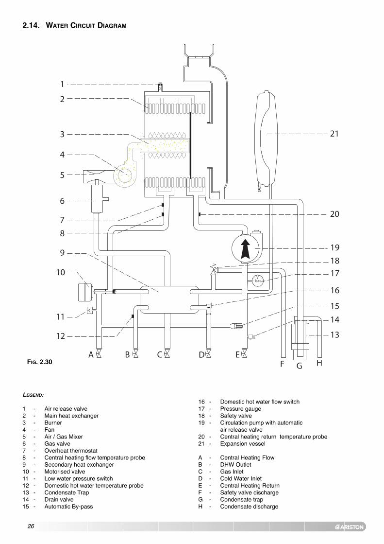
2.14. WATER CIRCUIT DIAGRAM
A B C D EF HG
bar
1
2
3
4
5
6
7
8
9
10
11
12 13
14
15
16
17
18
19
21
20
LEGEND:
1 - Air release valve2 - Main heat exchanger3 - Burner4 - Fan5 - Air / Gas Mixer6 - Gas valve7 - Overheat thermostat8 - Central heating flow temperature probe9 - Secondary heat exchanger10 - Motorised valve11 - Low water pressure switch12 - Domestic hot water temperature probe13 - Condensate Trap14 - Drain valve15 - Automatic By-pass
16 - Domestic hot water flow switch17 - Pressure gauge18 - Safety valve19 - Circulation pump with automatic
air release valve20 - Central heating return temperature probe21 - Expansion vessel
A - Central Heating FlowB - DHW OutletC - Gas InletD - Cold Water InletE - Central Heating ReturnF - Safety valve dischargeG - Condensate trapH - Condensate discharge
FIG. 2.30

27
3. COMMISSIONING
3.1. INITIAL PREPARATION MTS (GB) Limited support the initiative. In Sections 11and 12 of this manual you will find the commissioningchecklist (page 70) and the service interval record (Page 71), Itis important the commissioning checklist is completedin the presence of your customer, they are shown how to use it,and it is signed by them. Please instruct your customer that theymust have this manual with them whenever they contact aservice engineer or us.Preliminary electrical system checks to ensure electrical safetymust be carried out by a competent person i.e. polarity, earthcontinuity, resistance to earth and short circuit.
FILLING THE HEATING SYSTEM:Remove the case and lower the control panel (see section 3.2.for further information). Open the central heating flow and return cocks supplied withthe connection kit.Unscrew the cap on the automatic air release valve one fullturn and leave open permanently.Close all air release valves on the central heating system.Gradually open valve(s) at the filling point (filling-loop)connection to the central heating system until water is heard toflow, do not open fully. Open each air release tap starting with the lowest point andclose it only when clear water, free of air, is visible.Purge the air from the pump by unscrewing the pumpplug and also manually rotate the pump shaft in thedirection indicated by the pump label to ensure the pumpis free.
IMPORTANT!!OPEN THE MANUAL AIR VENT AND ENSURE THAT THE PRIMARY
EXCHANGER IS FREE OF AIR. (See FIG. 3.0)
Refit the pump plug.Continue filling the system until at least 1 bar registers on thepressure gauge.Inspect the system for water soundness and remedy any leaksdiscovered.
FILLING OF THE D.H.W. SYSTEM:Close all hot water draw-off taps.Open the cold water inlet cock supplied with the connection kit.Open slowly each draw-off tap and close it only when clearwater, free of bubbles, is visible
GAS SUPPLY:Inspect the entire installation including the gas meter, test forsoundness and purge, all as described in BS 6891:2005.Open the gas cock (supplied with the connection kit) to theappliance and check the gas connector on the appliance forleaks.
WATER TREATMENT:The boiler is equipped with a stainless steel heat exchanger.
The detailed recommendations for water treatment are givenin BS 7593:1992 (Treatment of water in domestic hot watercentral heating systems); the following notes are given forgeneral guidance;
If the boiler is installed on an existing system, anyunsuitable additives must be removed.
Under no circumstances should the boiler be fired before thesystem has been thoroughly flushed; the flushing procedure
Manual Air Vent
FIG. 3.0

28
must be in line with BS7593:1992. We highly recommend the use of a flushing detergentappropriate for the metals used in the circuit. These includecleansers produced by Fernox and BetzDearborn, whosefunction is to dissolve any foreign matter that may be in thesystem; In hard water areas or where large quantities of water are inthe system the treatment of the water to prevent prematurescaling of the main heat exchanger is necessary.
The formation of scale strongly compromises the efficiency ofthe thermic exchange because small areas of scale cause ahigh increase of the temperature of the metallic walls andtherefore add to the thermal stress of the heat exchanger.
Demineralised water is more aggressive so in this situation itis necessary to treat the water with an appropriate corrosioninhibitor.
Any treatment of water by additives in the system for frostprotection or for corrosion inhibition has to be absolutelysuitable for all the metals used in the circuit.
The use of a corrosion inhibitor in the system such as FernoxMB-1, BetzDeaborn Sentinel X100 or Fernox System Inhibitoris recommended to prevent corrosion (sludge) damaging theboiler and system;
If anti-freeze substances are to be used in the system, checkcarefully that they are compatible with the metals used in thecircuit.
MTS suggests the use of suitable anti-freeze products suchas Fernox ALPHI 11, which will prevent rust and incrustationtaking place.
Periodically check the pH of the water/anti-freeze mixture ofthe boiler circuit and replace it when the amount measured isout of the range stipulated by the manufacturer ( 7 < pH < 8). DO NOT MIX DIFFERENT TYPES OF ANTI-FREEZE
In under-floor systems, the use of plastic pipes withoutprotection against penetration of oxygen through the wallscan cause corrosion of the systems metal parts (metal piping, boiler, etc), through the formation of oxides andbacterial agents.
To prevent this problem, it is necessary to use pipes with an“oxygen-proof barrier”, in accordance with standards DIN4726/4729. If pipes of this kind are not used, keep thesystem separate by installing heat exchangers of thosewith a specific system water treatment.
IMPORTANT Failure to carry out the water treatment procedurewill invalidate the appliance warranty.
29
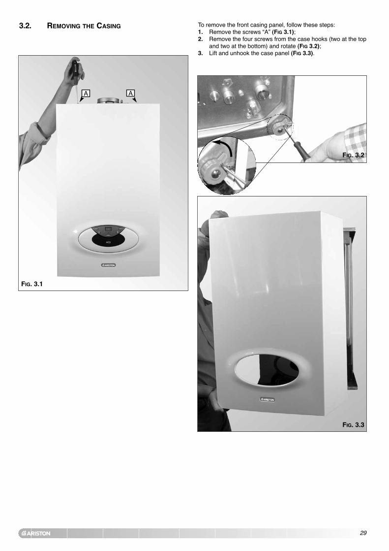
3.2. REMOVING THE CASING To remove the front casing panel, follow these steps:1. Remove the screws “A” (FIG 3.1);2. Remove the four screws from the case hooks (two at the top
and two at the bottom) and rotate (FIG 3.2);3. Lift and unhook the case panel (FIG 3.3).
FIG. 3.2
FIG. 3.3
FIG. 3.1
A A

30
3.3. CONTROL PANEL
FIG. 3.4
A
D
E
F
GH
I
C
B
** IMPORTANT!!The Flue Test function will cause the boiler to run continuously onmaximum power. This function must only be activated by anauthorised engineer.
Button Description
ON/OFF Button
“COMFORT” Function Push-button
Reset Button/Flue Test**/ scroll through Functions Menu
Menu Button
Programming “+” key
Programming “-” key
Description
A Green LED (illuminated = burner on)
B Time clock
C Selector knob for Summer/Winter Central Heating Temperature Adjustment Knob
D Control Panel Cover
E Domestic Hot Water Temperature Adjustment Knob
F Heating System Pressure Gauge
G “COMFORT” Function L.E.D
H Red LED(illuminated = boiler lockout)
I Multi-function Display
35 MFFI (Combi)

31
3.4. INITIAL START-UP 1. Make sure that:- the cap of the automatic air release valve is loosened;- the system pressure is at least 1 bar on the
pressure gauge “F” (Fig. 3.4);- the gas cock is closed (Fig. 3.7);- the electrical connection has been carried
out in the correct manner. To allow the air to escape from the system,
proceed as follows:- push the On/off button and turn the
knob “C” (Fig. 3.5) to the “winter” position. The boiler pump willstart up and three consecutive attempts will be made to ignitethe burner. After the third attempt, the electronic system willshutdown the boiler, because the supply of gas has been cut off.
The message “A01” will appear on the display and the red LED“H” will illuminate;
- let the pump operate until all the air has escaped from thesystem;
- repeat the procedure for bleeding the radiators of air;- draw hot water for a short while;- check the system pressure and, if it has gone down, fill it with
water until it returns to 1 bar.
2. Fill the boiler condensate trap with water (Fig. 3.6).N.B. In the event of a prolonged period of system shutdown,the condensate trap should be filled before any reneweduse. A shortage of water in the trap could temporarily leadto a small leakage of fumes into the air.
3, Ensure that the flue is fitted correctly.
4. Turn on the gas cock (Fig. 3.8) and checkthe seals on the connections, including theone for the burner, making sure that themeter does not signal the passage of gas.Check the connections with a soap solutionand eliminate any leaks.
5. Press the reset button , the boiler willattempt to light. If the burner does not light the first time, repeat the procedure.Note: Should the boiler fail to ignite check that no air is presentin the gas pipe.The boiler is configured in the factory for the gas type inquestion. To check the CO2 setting, please refer to Section3.6.3 (page 41).
6. Run the appliance in the DHW mode and check the correctoperation of the thermostat control.
7. Complete the commissioning checklist (page 70).
FIG. 3.5
C
H
FIG. 3.7
Fig. 3.8FIG. 3.6

32
3.5. DISPLAY: MESSAGES SHOWN DURING
NORMAL OPERATION
During operation of the boiler, while it is carrying out its normaloperations, the left-hand display shows a series of characters thatrefer to the operations indicated below:
0 No request for heatC Heatingc Pump overrun for heatingd Domestic hot waterh Pump overrun for domestic hot waterF Frost Protection
The right-hand display (two-digit) shows:- in CENTRAL HEATING mode: temperature of the Central Heatingsystem flow;- in DOMESTIC HOT WATER mode: temperature of the Domestic HotWater.
FIG. 3.9
LEFT RIGHT

33
3.6. OPERATING PARAMETERS
The boiler has been designed to allow easy use of the operatingparameters.
3.6.1 REGULATION MENU TABLE
Summary of the functions accessed when the RESET buttonand the menu button are pushed at the same time for
5 seconds. On the display will appear the parameters indicated in table 3A.To switch between the different parameters press the button.To modify the parameters push the programming keys and .
Fig. 3.10
Parameter Function Range Factory setting
1Soft lightas % of maximum Heating Power(NG)
from 00 to 9 9(step: 1%) 5 8
2 Maximum Heating Power (%) from 00 to 9 9(step: 1%) 6 0
3 Ignition delay (minutes) from 00 to 0 7(step: 1 minute) 0 2
4Central heating minimumtemperature
25°C if parameter r = 0042°C if parameter r = 01
4 2
5Central heating maximumtemperature
75°C if parameter r = 0082°C if parameter r = 01
8 2
6
P∆T rpm (Check of the temperaturedifference between the flow andreturn sensors for twelve seconds oninitial start-up - DO NOT ADJUST)
4 5
t/S NOT USED
F Boiler types from O0 to 0 2 0 0
e Secondary outlet function from 00 to 0 3 0 0
pPump overrun (Central Heating -mins) from 01 to 15 or CO 0 2
c Comfort function from 00 to 0 1 0 0
pPump speed adjustment (modulatingor single speed)
U0 (single speed)U1 (modulating)
U 1
TABLE. 3A

34
Important!!The parameters P5 and P6 are only enabled when theoutdoor sensor is activated (Parameter P - page 37-38).
To return to the normal display, press the menu button .
Parameter Function Range Factory setting
rselects low temperature systems or standard systems
00 (Low temperature)01 (Standard System)
0 1
p 9Temperature regulation controlled byexternal sensor
90 (Disabled)91 (Enabled)
9 0
p 6 Correction of heat curve translation from -20 to + 2 0
P 5 Curve incline from 0_1 to 5 _ 0 0 _ 9
t Test Function
A Bus Address (Do not modify)
b 0 Set-point second heating zone from 25 to 8 2 7 5
b 1 GSM value (Do not modify)
b 2Heating delay after commutation inDHW (from 0 to 30 minutes)
from 00 to 3 0(step: 1 minute) 0 0
b 3 Post-ventilation in Heating mode 0 (Disabled)1 (Enabled)
1
b 4 NOT USED
b 5 NOT USED
b 7 NOT USED
b 8 NOT USED

35
FIG. 3.11
Soft Light adjustment 1The soft light can be adjusted between the maximum power(shown on the display as “99”) and the minimum power (shownon the display as “00”). The boiler is factory set to a value whichis suitable for the ignition with any type of gas.The value set expressed as a percentage, can be displayed andadjusted as indicated in Section 3.6.1 (parameter 1)
FIG. 3.12
Maximum Heating Power adjustment 2The maximum heating power can be adjusted between themaximum power allowed by the boiler (29.4kW) and theminimum recommended power (6.5 kW) indicated in the graphbelow. The value is factory set to 70% of the maximum power.The value set (expressed as a percentage) can be displayedand modified as illustrated in Section 3.6.1 (parameter 2).The display shows the value between 100% ("99" on the display)and 1% ("00").
Use the graph below as a guide to set the boiler heating power tosuit the system load.
29.4
6.5
Display
Hea
t O
utp
ut
Ignition Delay adjustment 3The re-ignition delay for Central Heating can be adjusted tobetween 0 and 7 minutes. The delay is factory set to 2 minutes.The value set can be displayed and modified as illustrated inSection 3.6.1 (parameter 3)
FIG. 3.13

Secondary outlet Function E(This parameter can be modified only with theinterface PCB connected)With the interface PCB connected, it is possible to set the boilerto operate with one of the following accessories, (see Section2.12 for further information). The setting can be varied bypushing the and keys, the following options are available:
0 0 zone valve - factory setting - (NOT USED IN UK)
0 1 NOT USED
0 2 NOT USED
0 3 NOT USED
36
PUMP OVERRUN PThe pump overrun time may be adjusted (after the burner has beenturned off) by pressing the programming keys and . The following modes are available:
0 1 1 minute of pump overrun
0 2 2 minutes of pump overrun - factory setting
0 3 3 minutes of pump overrun
0 4 4 minutes of pump overrun
..... .............................
1 5 15 minutes of pump overrun
FIG. 3.17
FIG. 3.16
Boiler types FFactory setting:00 - ACO 35 MFFI (COMBI)THIS PARAMETER MUST NEVER BE ADJUSTED.
Maximum Central Heating temperature 5This parameter allows the setting of the maximum temperature forthe central heating circuit. The value is factory set at 82°C andcan be adjusted as illustrated in Section 3.6.1 (parameter 5).
Minimum Central Heating temperature 4This parameter allows the setting of the minimum temperature forthe central heating circuit. The value is factory set at 46°C andcan be adjusted as illustrated in Section 3.6.1 (parameter 4).
FIG. 3.15
FIG. 3.14
37
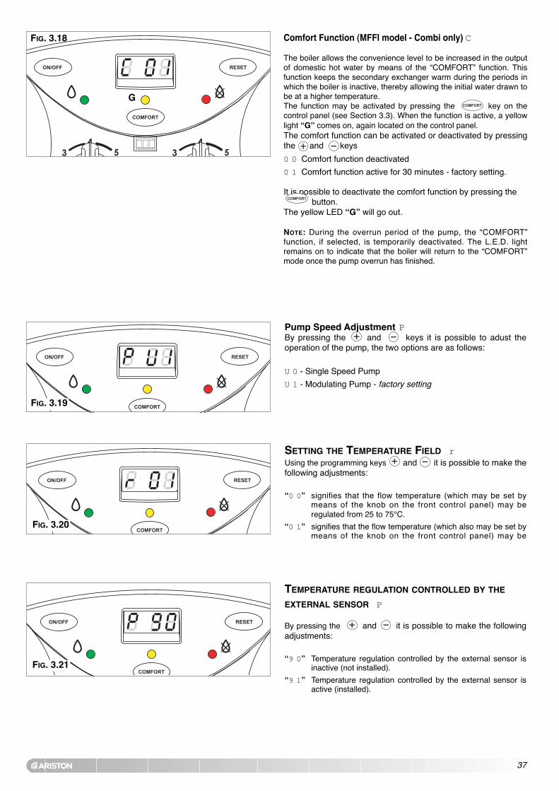
Pump Speed Adjustment PBy pressing the and keys it is possible to adust theoperation of the pump, the two options are as follows:
U 0 - Single Speed Pump
U 1 - Modulating Pump - factory setting
FIG. 3.19
FIG. 3.18 Comfort Function (MFFI model - Combi only) C
The boiler allows the convenience level to be increased in the outputof domestic hot water by means of the “COMFORT” function. Thisfunction keeps the secondary exchanger warm during the periods inwhich the boiler is inactive, thereby allowing the initial water drawn tobe at a higher temperature. The function may be activated by pressing the key on thecontrol panel (see Section 3.3). When the function is active, a yellowlight “G” comes on, again located on the control panel.The comfort function can be activated or deactivated by pressingthe and keys
0 0 Comfort function deactivated
0 1 Comfort function active for 30 minutes - factory setting.
It is possible to deactivate the comfort function by pressing the button.
The yellow LED “G” will go out.
NOTE: During the overrun period of the pump, the “COMFORT”function, if selected, is temporarily deactivated. The L.E.D. lightremains on to indicate that the boiler will return to the “COMFORT”mode once the pump overrun has finished.
G
TEMPERATURE REGULATION CONTROLLED BY THE
EXTERNAL SENSOR P
By pressing the and it is possible to make the followingadjustments:
“9 0” Temperature regulation controlled by the external sensor isinactive (not installed).
“9 1” Temperature regulation controlled by the external sensor isactive (installed).
SETTING THE TEMPERATURE FIELD rUsing the programming keys and it is possible to make thefollowing adjustments:
“0 0” signifies that the flow temperature (which may be set bymeans of the knob on the front control panel) may beregulated from 25 to 75°C.
“0 1” signifies that the flow temperature (which also may be set bymeans of the knob on the front control panel) may be
FIG. 3.20
FIG. 3.21

38
SETTING THE CURVE INCLINE P 5(Only enabled when an outdoor sensor is installed)When using an outdoor sensor, the microprocessor-controlledP.C.B. calculates the most suitable flow temperature, taking intoaccount the external temperature and the type of system. Themicroprocessor is capable of doing this because it is possible toestablish a link between the external temperature and the flowtemperature of the Central Heating system water. This linktranslates into a "thermal curve".The type of curve should be chosen in correspondence with theplanned temperature of the system and the nature of the heat losspresent in the building.
To select the type of curve access the Setting Menu by pressing theand buttons for 5 seconds and proceed as follows;
1. Press the button four times to access Parameter 5;
2. P 5 will be shown on the left hand display;3. Choose the curve required for the system from Fig. 3.26 and
select by pressing the and buttons.FIG. 3.25
FIG. 3.24
ADAPTING THE HEAT CURVE “P 6”(Only enabled when the outdoor sensor is activated)Should the external sensor be fitted it will be necessary to set theheating curve (see below) and may be necessary to adjust the parallelshift depending on the performance of the heating system used.
If the temperature in the house is too high, it will be necessary todecrease the parallel shift, whereas if the temperature is too low it willbe necessary to increase the parallel shift as described below.
To set up the external sensor proceed as follows;
1. Access the settings menu by pressing the and buttons for five seconds;
2. Press the button 5 times to access Parameter 6
3. P 6 will now appear in the left hand display4. Adjust the parallel shift by turning the heating control knob
clockwise to increase or anti-clockwise to decrease as shown below. The shift value can be read on the right hand display, from-20 to +20 (Fig. 3.23).
+20
20
-20
6
60
100
-20 +20
-20 +20
to increase the curve in parallel
to decrease the curve in parallel
Flo
w te
mpe
ratu
re (
°C)
External temperature (°C)
FIG. 3.23
FIG. 3.22
39
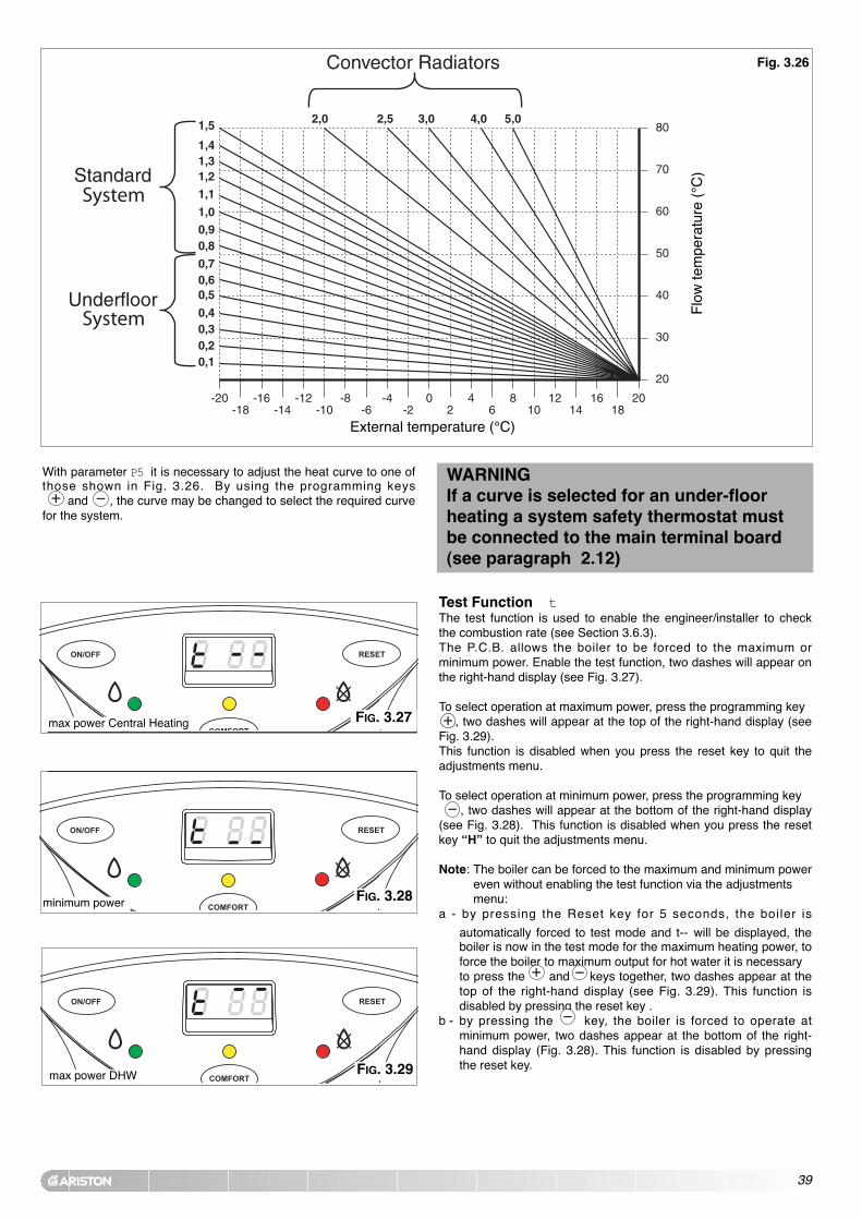
Test Function tThe test function is used to enable the engineer/installer to checkthe combustion rate (see Section 3.6.3).The P.C.B. allows the boiler to be forced to the maximum orminimum power. Enable the test function, two dashes will appear onthe right-hand display (see Fig. 3.27).
To select operation at maximum power, press the programming key , two dashes will appear at the top of the right-hand display (see
Fig. 3.29).This function is disabled when you press the reset key to quit theadjustments menu.
To select operation at minimum power, press the programming key , two dashes will appear at the bottom of the right-hand display
(see Fig. 3.28). This function is disabled when you press the resetkey “H” to quit the adjustments menu.
Note: The boiler can be forced to the maximum and minimum powereven without enabling the test function via the adjustments menu:
a - by pressing the Reset key for 5 seconds, the boiler is
automatically forced to test mode and t-- will be displayed, theboiler is now in the test mode for the maximum heating power, toforce the boiler to maximum output for hot water it is necessary to press the and keys together, two dashes appear at thetop of the right-hand display (see Fig. 3.29). This function isdisabled by pressing the reset key .
b - by pressing the key, the boiler is forced to operate atminimum power, two dashes appear at the bottom of the right-hand display (Fig. 3.28). This function is disabled by pressingthe reset key.
max power Central Heating
minimum power
FIG. 3.27
FIG. 3.28
With parameter P5 it is necessary to adjust the heat curve to one ofthose shown in Fig. 3.26. By using the programming keys
and , the curve may be changed to select the required curvefor the system.
WARNINGIf a curve is selected for an under-floorheating a system safety thermostat mustbe connected to the main terminal board(see paragraph 2.12)
Fig. 3.26
max power DHW FIG. 3.29
Flo
w te
mpe
ratu
re (
°C)
External temperature (°C)

40
The boiler is designed to monitor some operating variables andsettings by means of the display on the front control panel. Keeping,at the same time, the reset and the menu key pressed for over 10seconds will allow access to the “readout” function of the mainsystem variables. By pressing the reset button repeatedly after that,it is possible to read the following information in sequence:
Indication on the left-hand display
U / 1
U / 2
U / 3
U / 4
U / 6
E
A
Value read on right-hand display
Flow temperature of the Central Heating circuit (°C)
Return temperature of the Central Heating circuit (°C)
Domestic Hot Water output temperature (°C)
Outdoor temperature (°C)*
Fan speed (% rpm)
Last safety shut-off (see section 3.10.)
Last shutdown (see section 3.10.)
3.6.2 SETTINGS DISPLAY
To return to the normal display, press the menu key.The boiler will automatically return to the normal display after nobuttons have been pressed for 2 minutes.
NOTE 1: U/1 means that “U ” and “1 ” blink alternately on the display
NOTE 2: the value 100% appears as “9 9” on the display* = Only displayed when an external sensor is fitted.

41
SUPPLY PRESSURE (WORKING)
G20 methane 20 mbarLPG 37 mbar
1
23
4
3.6.3 GAS REGULATION CHECK Supply pressure check1. Loosen screw “1” (Fig. 3.31) and connect the pressure gauge
connection pipe into the test point.2. Turn the boiler on at maximum power, enabling the “test”
function (press the key for 5 seconds and then press theprogramming keys and together ensuring the dashes areat the top of the display (see Fig. 3.29). The supply pressureshould correspond to that shown for the type of gas the boiler isdesigned for (see table below).
3. Disable the test mode by pressing the reset key.4. When the check is over, tighten screw “1” and test for tightness.
NOTE: IF THE WORKING PRESSURE IS INSUFFICIENT CHECK THE GAS
METER, METER GOVERNOR, OR INSTALLATION PIPEWORK FOR
ERROR.
IMPORTANT!DO NOT PROCEED CHECKING AND ADJUSTING THE CO2 SETTINGS
UNLESS THE WORKING PRESSURE IS ADEQUATE.
NOTE: ALL SETTINGS ARE TO BE MADE WITH A CO2 METER WITH THE
PROBE FITTED TO THE FLUE GAS ANALYSIS POINT (FIG. 3.30).
Setting the CO2 at minimum powerTo check the air/gas ratio at minimum power, proceed as follows:1. Connect the combustion analyser to the analysis point (Fig.
3.30) after removing the screw and cover.2. Set the boiler to minimum power via the test function (see
paragraph 3.6.1) or by pressing the button for 5 secondsand then pressing the button on the control panel, ensurethe dashes are at the bottom of the display (see Fig. 3.28).Ensure the CO2 value on the analyser corresponds with thevalue indicated in table 4D. If this is not the case, adjust screw“2” (Fig.3.31) with a screwdriver in small intervals, allowing thereading to become stable before adjusting further, until youobtain the correct CO2 reading. Allow the reading to becomestable for at least 4 minutes.
3. When the check is over, replace the cap on screw “2” (Fig. 3.31).4. Disable operation at minimum power by pressing the key
or press the key to check the maximum value (dashes at topof display see Fig. 3.29).While the appliance is operating at maximum power, checkthe gas rate of the appliance at the gas meter
Setting the CO2 at maximum powerTo check the air/gas ratio at maximum power, proceed as follows:1. With the combustion analyser already connected to the analysis
point, set the boiler to maximum power via the test function (seeparagraph 3.6.1) or by pressing the button for 5 secondsand then the programming keys and ensuring the dashesare at the top of the display (see Fig. 3.29).Ensure the CO2 value on the analyser corresponds with thevalue indicated in table 4D. If this is not the case, adjust screw“4” with a screwdriver in small intervals allowing the analyserreading to stabilise before adjusting further (Fig. 3.31), until youobtain the correct CO2 reading. Allow the reading to becomestable for at least 4 minutes.
2. Disable the test mode by pressing the button.The test mode is automatically disabled after 5 minutes.
3. Repeat the air/gas ratio at minimum power check (seeabove).
4. Disconnect the analyser, remount the cover plate and check it issecurely in place.
While the appliance is operating at minimum power, checkthe gas rate of the appliance at the gas meter
NOTE: WHEN MAKING ADJUSTMENTS, ADJUST SMALL AMOUNTS AND
WAIT FOR THE ANALYSER TO STABILISE BEFORE MAKING
FURTHER ADJUSTMENTS.
CO2 SETTING MAXIMUM VALUE
Calibration values check CO2 at maximum power G20 % vol 9.4 ±0.2after 4 minutes of operation
LPG % vol 10.1 ±0.2
CO2 SETTING MINIMUM VALUE
Calibration values check CO2 at minimum power G20 % vol 8.7 ±0.2after 4 minutes of operation
LPG % vol 8.6 ±0.2
SETTING THE GAS PRESSURES
FIG. 3.32
FIG. 3.31
TABLE 4D
FIG. 3.30

42
The soft light can be adjusted between the maximum power(shown on the display as "99", i.e. 100%) and minimum power(shown on the display as "00", i.e. 1%). The boiler is factory set toa value which is suitable for ignition with any type of gas.The value set (expressed as a percentage) can be displayed andmodified as illustrated in paragraph 3.6.1 (parameter 1).
The ignition delay can be adjusted to between 0 and 7 minutes.The delay is factory set to 2 minutes. The value set can be displayed and modified as illustrated inparagraph 3.6.1 (parameter 3).
3.6.4 IGNITION DELAY ADJUSTMENT
3.6.5 ADJUSTING THE MAXIMUM HEATING POWER
3.6.6 SOFT LIGHT ADJUSTMENT
The maximum heating power can be adjusted between themaximum power allowed by the boiler (29.4kW) and the minimumpower (6.5 kW) indicated in the graph. The value is factory set to70% of the maximum power.The value set (expressed as a percentage) can be displayed andmodified as described in paragraph 3.6.1 (parameter 2) using thegraph on Page 35.
3.7 CHANGING THE TYPE OF GASThe boiler operation can be changed over from methane gas(G20) to Liquid Gas (G31) or vice versa, an operation that mustbe performed by a CORGI registered Gas Engineer.
To change the type of gas it is necessary to proceed as follows:1. Before starting ensure both the gas and electrical supplies
to the boiler are isolated and the boiler is cool.2. Remove the casing as indicated in Section 3.2.3. Remove the silencer4. Disconnect the electrical connection of gas valve and fan.5. Remove the three torx screws of the air gas connections
(see Fig. 3.32) and loosen the nut under the gas valve (see Fig. 3.33)
5. Remove all the mixer/fan/gas valve group (see Fig. 3.34)6. Unscrew the four torx screws and disconnect the gas valve (see
Fig. 3.35).7. Insert the diaphram into the gas valve (see Fig. 3.36)8. Reassemble in reverse order.9. Replace the gas label.
FIG. 3.32
FIG. 3.33
FIG. 3.34

43
3.8 ADJUSTING THE HOT WATER FLOW RATETo adjust the hot water flow rate, it is necessary to first open the hotwater tap with the highest flow rate (normally the bath tap), adjust thecold water inlet valve until the correct temperature rise is achieved at thestated flow rate ( ACO 35 MFFI - ∆T@35°C = 13.5 l/min).
Alternatively, you can advise the customer to restrict the water flowthrough each individual tap, by opening the tap and slowly closing ituntil the water reaches the desired temperature.
3.9 BALANCING THE CENTRAL HEATING SYSTEMTo balance the central heating system it is first necessary to closeall radiator valves on the system, turn on the central heating, allowthe boiler to reach operating temperature and then starting at theradiator furthest from the boiler, open the radiator valves until theradiator becomes hot and move to the next radiator on the circuit,working your way back to the radiator closest to the boiler.
10. Carry out check 3.6.3, verifying the inlet pressure is correct and the CO2 values are as stated in Table 4D (page 41).
11. Check the gas connection for tightness.12. Check that the ignition operates correctly and visually check the
burner flame.13. Check that the domestic hot water is being correctly produced
by drawing hot water.14. Check the flow rate and/or temperature of the water, depending
on the case.15. Check that the condensate drips without difficulty into the
discharge.
FIG. 3.35 FIG. 3.36
LPG (G31)
Consumption at Nominal Capacity(G31) kg/h 2.33Gas Consumption after 10 Minutes* kg 0,27
* Calculated at 70% maximum output

44
NOTE: When there is no ignition (A01), check that the gas cock is open and gas is being supplied.
3.10 BOILER SAFETY SYSTEMS The boiler is protected from malfunctioning by means of internalchecks by the P.C.B., which brings the boiler to a stop if necessary.In the event of the boiler being shut off in this manner, a codeappears on the display which refers to the type of shut-off and thereason behind it.There are two types of shut-off:
- SAFETY SHUTDOWN: for this group of errors (characterised
on the display by the letter “E ”) the situation is automaticallyremoved as soon as the cause behind it is resolved.As soon as the origin of the shutdown disappears, the boilerstarts up again and returns to its normal operation.
- SHUTDOWN: (characterised on the display by the letter “A ”), isnot removed unless a manual intervention is made.The boiler may return to operation only if reset, press the
button.There follows a list of the shutdown modes and the respectivecodes shown on the display.
Shutdown (“A ” type): if such a situation occurs, it is necessary toreset the boiler using the appropriate key. If this shutdown occursfrequently, your local Service Agent should be contacted.
Safety shutdown: In the event that a safety shutdown occurs, it isnecessary to contact an Authorised Service Centre.
DISPLAY CAUSE
A 01 Too many attempts to ignite on start up
A 03The heating flow temperature exceeds 105°Cduring operation
A 07Too many failures to ignite in one periodduring operation
A 33 Problem with the fan
A 97 Problem with the electronic monitoring
A 98 Problem with the electronic monitoring
A 99 Problem with the electronic monitoring
DISPLAY CAUSE
E 02No water or no water circulation in centralheating system (for 40 sec.)
E 06 Heating flow temperature probe in open circuit
E 07 Heating flow temperature probe in short-circuit
E 08Heating return temperature probe in open circuit
E 09Heating return temperature probe in short-circuit
E 10Under floor heating temperature probe in open circuit
E 20 Flame detected with gas valve closed
E 94 Problem within the electronic system
E 99 Problem within the electronic system
DISPLAY CAUSE
S 01 Ignition failure on 1st attempt
S 02 Ignition failure on 2nd attempt
S 04Domestic hot water temperature probe in open circuit
S 05Domestic hot water temperature probe in short circuit
S 06 Problem with rectification probe
S 30 Outdoor sensor open circuit
S 31 Outdoor sensor in short circuit
S 80Remote Control CLIMA MANAGER roomsensor in open circuit or short circuit

45
The draining of the heating system must be carried out as follows:- Turn off the boiler and isolate the electrical supply;- Loosen the automatic air release valve;- Open the system's discharge valve- Empty out from the lowest points of the system (where
provided).If the system is to be left active in areas where the roomtemperature may go below 0°C during winter, it is recommendedthat anti-freeze liquid be added to the water in the heating system inorder to avoid the need for repeated draining.
Draining the domestic hot water systemEvery time that there is a danger of freezing, the domestic hot watersystem must be drained as follows:- close the water mains stop-cock;- open all the hot and cold water outlets;- empty out from the lowest points (where provided).
3.12 DRAINING
3.11 COMPLETION
DAILY TEST. In order to prevent sticking components, the boiler carries out a self-diagnosing test every 21 hours: the pump runs for 15 seconds andthe diverter valve moves once.ANTI-FROST DEVICE. The anti-frost function acts on the central heating flow temperatureprobe, independently from other regulations, when the electricalsupply is turned on.If the primary circuit temperature falls below 8°C the pump will runfor 2 minutes.After the two minutes of circulation (fixed) the boiler will check thefollowing:a) if the central heating flow temperature is > 8°C, the pump stops;b) if the central heating flow temperature is between 3 and 8°C, thepump will run for another two minutes;c) if the central heating flow temperature is < 3°C, the burner will fire(heating position) at minimum power until the temperature reaches33°C, the burner will go out and the pump will continue to run fortwo minutes.If the flow temperature remains between 3-8°C the pump willcontinue to run for two minutes for a maximum of 10 times unless atemperature above 8°C is detected in the central heating flow, afterthis the the burner will fire.If lockout is caused by overheat the burner is kept OFF.
NOTE: In all cases, the circulation takes place in the centralheating system.The anti-frost device activates only when (with the boileroperating correctly):- the system pressure is correct;- the boiler is electrically powered;- there is a supply of gas.
ANTI-SCALE DEVICE. When producing domestic hot water, the burner shuts offwhenever the output temperature of the hot water exceeds61°C or the flow temperature of the primary circuit exceeds78°C. It will not turn on if the temperature of the primary circuitis greater than 78°C.
For the Republic of Ireland it is necessary to complete a“Declaration of Conformity” to indicate compliance to I.S. 813. Anexample of this is given in the current edition of I.S. 813. In additionit is necessary to complete the commissioning checklist(Section 11, page 70).

46
5. SEQUENCE OF OPERATION
Activation of the time clock and/or room thermostat starts the boiler.
The letter C is shown in the display fol lowed by the flowtemperature.
With the boiler in rest, the diverter valve is in the domestic hot waterposition, activation of the central heating changes the position of themotorised valve head, moving the diverter valve into the centralheating position.
The start of the pump is delayed for 7 seconds to allow themovement of the diverter valve.The pump starts at speed 2, after the low water pressure switchverfies water is present. If the low water pressure switch does not verify water is present
after 40 seconds, error code E 0 2, the boiler will resume operation
once the problem has been resolved.
Following the satisfaction of the low water pressure switch check thefan starts and an ignition attempt is then made for 3 seconds afterthe fan starts. The gas valve is energised and gas is delivered tothe burner fixed in relation to the fan. The ignition gas pressure (softlight) is adjusted at Step 1 in the parameter adjustment mode (seeSection 3.6.1). This value is factory set. (1= minimum fan speedand 00 = maximum fan speed). Soft light takes 4 seconds, theelectronics check for flame ionisation three times consecutively.
Failure on ignition results in the error code A 0 1.
The boiler will modulate the burner according to the central heatingoutput. The burner can activate up to a maximum of the set point at+4oC. Reignition of the burner occurs once it has thermostaticallyturned off can be time delayed between 0 and 7 minutes, adjustablein Step 3 (Section 3.6.1), the factory setting is 2 minutes.
Overheat safety is provided by a Klixon thermostat, the temperatureis set to 105 ±1oC, this thermostat remains active even when theburner is off. In the event that the Klixon thermostat reads atemperature value above 105 ±1oC the boiler will shut down and the
display will show A 0 3, the fan will continue to run for 20 seconds.
After correct operation is proven the pump speed changes to speed3 (if the system is cold), if the system is warm the pump remains atspeed 2.
5.1 CENTRAL HEATING MODE
5.2 DOMESTIC HOT WATER MODE
When a hot water tap is turned on the domestic hot water flowswitch is operated (if the diverter valve is in the central heatingposition it will motor into the domestic hot water position and the
boiler starts. The letter d is shown in the display followed by thetemperature of the domestic hot water leaving the appliance.
The appliance will then follow the same operating logic as describedin Central Heating Mode.
In domestic hot water mode NTC1 limits the maximum temperatureto 78oC, reignition will occur at 74oC. The domestic hot watertemperature is limited to 61oC, reignition will occur at 60oC.
47
6. MAINTENANCE6.1. GENERAL REMARKS
To ensure the validity of the 5 Year Guarantee, the boiler must beserviced annually by a CORGI registered gas engineer.
MTS (GB) Limited will write to the householder as the boilerbecomes due for it’s annual service.
With the letter will also be sent a ‘Service Pack’, this will include theannual maintenance checklist to be completed and signed by theCORGI registered engineer, also included in this pack may be acomponent which must be replaced and the old one returned with alldocumentation included in the ‘Service Pack’ to MTS (GB) Ltd.
See Section 10 for annual maintenance requirements.
NOTE: FAILURE TO COMPLY WITH THE ANNUAL SERVICE
REQUIREMENTS WILL RESULT IN THE 5 YEAR GUARANTEE
BECOMING VOID.
CLEANING THE EXHAUST SIDEAccess the combustion chamber (see section 7.3). Check that theexhaust passages are clear; if there are deposits present, wash theexchanger with compressed air, water or a vinegar-based detergent.NOTE: it is possible to use a brush in order to mechanically removethe residues.
Use of detergents:- soak the blades well- allow the detergent to act for about 20 minutes- rinse with a strong jet of water to remove the deposits (the
control panel must be kept closed)- make sure that there are no traces of detergents in the
exchanger.
CLEANING THE WATER SIDEUse detergents that dissolve CaCO3. Leave to act for a short timeand then rinse. Make sure that the detergent does not remain insidethe exchanger.
To clean the condensate trap it is simply necessary to unscrew thelower part of the condensate trap and clean it. Lastly, fill it with waterand replace the stopper.
6.2. CLEANING THE PRIMARY EXCHANGER
6.3. CLEANING THE CONDENSATE TRAP
6.4. OPERATIONAL TEST
After having carried out the maintenance operations, fill theheating circuit to a pressure of approx. 1.5 bar and release theair from the system. Also fill the domestic hot water system.- Place the boiler in operation;- If necessary, release the air again from the heating system.- Check the settings and the correct functioning of all the
control, regulation and monitoring parts;- Check the seal and the correct functioning of the system for
expelling fumes/drawing of combustion air;- Check that the boiler ignites properly and carry out a visual
check on the burner flame; - Check the CO2 values are correct (see Section 3.6.3)
IMPORTANT!!
If the boiler is not to be used for a prolonged period, thecondensate trap should be filled before operating theboiler. A shortage of water in the trap will temporarilyrisk flue gasses escaping into the room.

48
FIG. 7.1
7. SERVICING INSTRUCTIONS
The life of individual components vary and they will need servicing orreplacing as and when faults develop.The fault finding sequence chart in Section 8 will help to locate whichcomponent is the cause of any malfunction, and instructions forremoval, inspection and replacement of the individual parts are givenin the following pages.
7.1. REPLACEMENT OF PARTS
7.2. TO GAIN GENERAL ACCESS All testing and maintenance operations on the boiler require thecontrol panel to be lowered. This will also require the removal of thecasing.
To lower the control panel and remove the casing,proceed as follows:
1. Remove the screws “A” (Fig. 7.1);2. Loosen the four screws ‘B’ from the case hooks (two
at the top and two at the bottom) and rotate (Fig. 7.2);3. Lift and unhook the case panel (Fig. 7.3);4. Lower the control panel (Fig. 7.4)
To ensure efficient safe operation, the boiler must be servicedannually by a competent person.
Before starting any servicing work, ensure both the gas andelectrical supplies to the boiler are isolated and the boiler iscool.Before and after servicing, a combustion analysis should be madevia the flue sampling point (please refer to Section 3.6.3).
After servicing, preliminary electrical system checks must be carriedout to ensure electrical safety (i.e. polarity, earth continuity,resistance to earth and short circuit).
AA
FIG. 7.3
FIG. 7.2
B

49
7.3.1. REMOVING THE AIR/GAS ASSEMBLY
1. Remove the three torx screws “C” (FIG. 7.5);2. Loosen the nut “D“ under the gas valve (FIG. 7.6);3. Disconnect electrical connections to gas valve and fan;4. Dismount the gas valve/mixer/fan group (FIG. 7.7);5. Reassamble in reverse order.
FIG. 7.5
FIG. 7.6
C
D
7.3. ACCESS TO THE COMBUSTION CHAMBERFIG. 7.4
To gain better acess to certain components, it will benecessary to remove the silencer.

50
FIG. 7.7
7.3.2. REMOVING THE BURNER
1. Remove ther air/gas assembly see section 7.3.1;2. Slide the burner from its housing (FIG. 7.8);3. Reassemble in reverse order and check all seals are
undamaged and the burner is positioned correctly.
FIG. 7.8
FIG. 7.9
FIG. 7.10
FIG. 7.11
7.3.3. REMOVING THE DETECTION ELECTRODE
1. Remove the two torx screws “E” (FIG. 7.9);2. Extract the electrode (FIG. 7.10);3. Disconnect the detection electrode cable (FIG. 7.11).
E

51
FIG. 7.12
FIG. 7.14
FIG. 7.13
7.3.4. REMOVING THE IGNITION ELECTRODE
1. Remove the earth cable from the electrode (FIG. 7.12);2. Remove the electrode cable from the spark generator
(FIG. 7.13);3. Unscrew the two screws “F” (FIG. 7.14).
F
1. Remove ther air/gas assembly see section 7.3.1;2. Disconnect the air/gas connection unscrew the three
screws “G“ (FIG. 7.15);3. Remove the mixer by unscrewing the two screws “H” (FIG.
7.16).4. Remove the fan (FIG. 7.17).
7.3.5. REMOVING THE FAN
FIG. 7.16
H
H
FIG. 7.15
G
FIG. 7.17

52
FIG. 7.207.3.6. REMOVING THE HEAT EXCHANGER
1. Drain the boiler;2. Remove the air/gas assembly see section 7.3.1;3. Remove the electrodes see section 7.3.3 - 7.3.4;4. Remove the condensate trap tube see section 7.3.7;5. Unplug the C.H. return and flow temperature probes
and the overheat thermostat (FIG. 7.18);6. Unplug the pipe clips (FIG. 7.18);7. Loosen the nut “I” and remove the pipe (FIG. 7.19 - 7.20);8. Loosen the nut “J” and remove the pipe (FIG. 7.21 - 7.22);9. Loosen the nuts “K” and remove the exchanger
(FIG. 7.23 - 7.24).
FIG. 7.18
FIG. 7.22
FIG. 7.23
FIG. 7.21
FIG. 7.19
J
I
ATTENTION!!When removing the heat exchanger, ensure thatno water can enter the electrical box containingthe PCB!
K
K
K

53
7.3.7. REMOVING THE CONDENSATE TRAP (TUBE)
1. Unplug the clip “L” (FIG. 7.25);2. Unscrew the screw “M” (FIG.7.26);3. Remove the condensate tube (FIG. 7.27).
FIG. 7.27
FIG. 7.24
FIG. 7.25
FIG. 7.26
L
M

54
FIG. 7.28
FIG. 7.29
7.3.8. REMOVING THE CONDENSATE TRAP
1. Remove the condensate trap tube - see section 7.3.7;2. Remove the condensate trap glass (FIG. 7.28);3. Remove the trap from the boiler (FIG. 7.29).
NOTE: Take care when removing the blanking cap toplace a container under the boiler as this willrelease the contents of the condensate trap.
7.4 ACCESS TO THE GAS VALVE
FIG. 7.30
FIG. 7.31
1. Remove the casing and lower the control panel as instructed in Section 7.1.
2. Press the release button “N” for the control panel (Fig.7.30) and pull forward to remove from the boiler frame.
3. Clip the control panel onto the frame of the boiler. (Fig.7.31).
N

55
7.4.1. REMOVING THE GAS VALVE
1. Remove the air/gas assembly see section 7.3.1; 2. Remove the screws “O” from the bottom of the gas
valve (FIG. 7.32);3. Remove the gas valve;
FIG. 7.32
O
7.4.2. REMOVING THE SPARK GENERATOR
1. Disconnect the electrical connection from the sparkgenerator (FIG. 7.33);
2. Remove the screws “P” from the bottom of the sparkgenerator (FIG. 7.34);
4. Remove the spark generator.
FIG. 7.33
FIG. 7.34
PP
4. Reassemble in reverse order;5. The gas valve settings will need to be adjusted (see
section 3.6.3);6. Reinstate the gas supply and test for tightness on
reassembly.

56
7.5 ACCESS TO THE WATER CIRCUIT
7.5.1. REMOVING THE D.H.W. (SECONDARY) EXCHANGER
1. Remove the two allen screws “Q” (FIG. 7.35 and 7.36);2. Push the exchanger towards the rear of the boiler, lift
upwards and remove from the front of the boiler (FIGS.7.37, 7.38 and 7.39);
3. Before replacing the exchanger ensure that the O-ringsare in good condition and replace if necessary.
Important! Before any component is removed, the boilermust be drained of all water.
FIG. 7.35
FIG. 7.37
FIG. 7.38
FIG. 7.39
Q
Q
FIG. 7.36

57
7.5.2. REMOVING THE SAFETY VALVE
1. Loosen the nut “R” and remove the pipe (Fig. 7.40);2. Remove the valve (Fig. 7.41).
FIG. 7.40
FIG. 7.41
7.5.3. REMOVING THE AUTOMATIC AIR VENT
1. Remove the U-clip “S” (FIG. 7.42);2. Remove the automatic air vent (FIG. 7.43).
FIG. 7.43
FIG. 7.42
S
R

58
7.5.6. REMOVING THE PUMP
1. Unplug the electrical connection (FIG. 7.48);2. Unscrew the four screws “U” (FIG. 7.48);3. Remove the pump (FIG. 7.49).
FIG. 7.48
FIG. 7.49
7.5.5. REMOVING THE D.H.W. FLOW SWITCH
1. Unplug the electrical connector (FIG. 7.46);2. Remove the D.H.W. flow switch (FIG. 7.47).
FIG. 7.46
FIG. 7.47
FIG. 7.44
7.5.4. REMOVING THE DIVERTER VALVE ACTUATOR
1. Unplug the electrical connector and retaining clip “T”(FIG. 7.44);
2. Remove the diverter valve actuator (FIG. 7.45).
FIG. 7.45
T
T
TT
T

59
7.5.8. REMOVING THE PRESSURE GAUGE
1. Release U-clip “W” (FIG. 7.53 - 7.54);2. Ease the pressure gauge through the control panel
from the rear;3. Remove the pressure gauge.
FIG. 7.53
FIG. 7.54
W
7.5.7. REMOVING THE LOW WATER PRESSURE SWITCH
1. Disconnect the electrical connection (FIG. 7.50);2. Loosen the nut “V” (FIG 7.51);3. Remove the low water pressure switch. (FIG 7.52).
FIG. 7.50
FIG. 7.51
FIG. 7.52
V

60
7.5.10 REMOVING THE D.H.W. TEMPERATURE PROBE (N.T.C.)
1. Remove the electrical connector by pulling off andloosening the nut “Z” (Fig. 7.58);
2. Remove the D.H.W. temperature probe (FIG. 7.59).
FIG. 7.58
FIG. 7.59
7.5.9. REMOVING THE EXPANSION VESSEL
1. Unscrew the screw “X” (FIG. 7.55);2. Loosen nut “Y” (FIG. 7.56);3. Remove the expansion vessel (FIG. 7.57).
X
FIG. 7.55
FIG. 7.56
FIG. 7.57
Y
Z

61
FIG. 7.60
7.5.10. Removing the C.H. Flow TemperatureProbe (N.T.C.)
1. Unplug the C.H. Flow temperature probe (Fig. 7.60);2. Remove the electrical connection from the C.H. flow
temperature probe (FIG. 7.61).
FIG. 7.62
FIG. 7.63
7.5.11. REMOVING THE C.H. RETURN TEMPERATURE
PROBE (N.T.C.)
1. Unplug the C.H. Return temperature probe (Fig. 7.62);2. Remove the electrical connection from the C.H. return
temperature probe (FIG. 7.63).
FIG. 7.61
FIG. 7.64
7.5.10. Removing the Overheat Thermostat
1. Unplug the overheat thermostat (Fig. 7.64);2. Remove the electrical connection from the overheat
thermostat (FIG. 7.65).
FIG. 7.65

62
7.6.1. CHECKING THE FUSES
1. Remove the inspection cover of the PCB box (FIG. 7.66- 7.67);
2. Loosen the two screws “A1” and slide the PCBforward before removing the screws (FIG. 7.68).
7.6 ACCESS TO THE CONTROL SYSTEM
FIG. 7.66
FIG. 7.67
FIG. 7.68
A1
A1
7.6.2. REMOVING THE P.C.B.S
1. Remove the inspection cover of the PCB box (FIG.7.66- SECTION 7.6.7);
2. Unplug all the electrical connections and loosen thescrews “A1” (FIG. 7.68);
4. Pull forward the main PCB (FIG. 7.69 & 7.70);5. Unscrew the screws “A2” (Fig. 7.71);6. Remove the cover of the control panel (FIG. 7.72);7. Unscrew the display P.C.B. mounting screws “A3” and
disconnect the P.C.B. connection cable “A4” (FIG. 7.73);8. Remove the display P.C.B. (FIG. 7.74);9. Replace either P.C.B. in reverse order.
FIG. 7.69
FIG. 7.70
FIG. 7.71
A2
A2
A2

63
FIG. 7.72
FIG. 7.73
FIG. 7.74
7.6.3. REMOVING THE TIME CLOCK
1. Open the control panel (see the paragraph “Removingthe P.C.B.s”);
2. Unplug the electrical connection from the time clockand unscrew the four screws (FIG. 7.75);
3. Remove the time clock (FIG. 7.76).
FIG. 7.76
FIG. 7.75
A3A3
A3
A3
A4
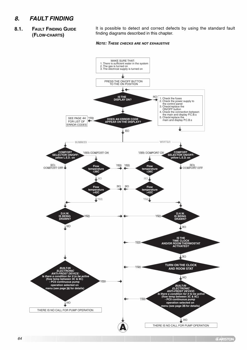
64
It is possible to detect and correct defects by using the standard faultfinding diagrams described in this chapter.
NOTE: THESE CHECKS ARE NOT EXHAUSTIVE
8.1. FAULT FINDING GUIDE
(FLOW-CHARTS)
8. FAULT FINDING

65
IS THELOW WATER
PRESSURE SWITCHWORKING CORRECTLY?
E 02:does not close
1. Check if there is air in the system2. Check the pressure on the water gauge and fill system to 1 bar
Push the RESET button

66

67
9. SHORT SPARE PART LIST
110
206
107
111
101
147 190
401
571
502
589
597548
564
537520
529
615
616
538
531
901
917
917
917
911
917904
35 MFFI
0101 MAIN EXCHANGER 651033850107 BURNER 651033330110 ELECTRODE (IGNITION) 651033580111 ELECTRODE (DETECTION) 65103359
0147 GASKET D:129.4 613060300190 SPARK GENERATOR 65103516
0206 FAN ASSY 613144340401 GAS VALVE 65103413
0502 MOTOR (3-WAY VALVE) 9971470520 TEMPERATURE PROBE (D.H.W.) 998458
0529 PRESSURE GAUGE 651022200531 AUTO AIR VENT + O-RING 995367
0537 SAFETY VALVE (1/2 3 BAR) 5731720538 KIT FOR REAR PUMP ATTACHMENT 65103500
0548 TEMPERATURE PROBE + CLIP 651035020564 FLOW DETECTION KIT WITH MAGNET 65100540
0571 LOW WATER PRESSURE SWITCH 9959030589 SECONDARY EXCHANGER 651035010597 THERMOSTAT (OVERHEAT) 996065
0615 P.C.B. (ACO-MCU) 651035080616 P. C. B. (DISPLAY) 651022350901 FILLING LOOP PIPE 990737
0904 TAP (M/M 3/8 ) 651020160911 TAP (M/M 3/8 - C.H. FLOW) 990742
0917 GASKET 3/8 573521

68
10. ANNUAL MAINTENANCE CHECKLIST
Annual Maintenance Check List
The flue has been checked to ensure it is:
The correct operation of the following components has been checked:
Sited in accordance with the manufacturers instructionsInstalled correctlyIs in good condition
Air Pressure SwitchThermostat ControlsSafety ValveIonisation (Flame Detection)
The following has been carried out:
Pressure in expansion vessel checked and corrected where necessary (0.7 bar)Condensate system removed, cleaned and refilledAuto Air Vent replaced and returned (see instructions over leaf)DHW flow switch removed and cleaned (Combi Only)Electrodes removed and cleaned (with emery cloth)Burner and fan removed and cleaned (if necessary)Primary heat exchanger checked and cleaned if necessaryAll electronic parameters checked and set as requiredTime clock and room thermostat checked for correct operation
Please check the following information:
Gas inlet pressure
DHW flow rate
Gas working pressureGas rateCO2 setting (min/max)
CO2 ratio
(∆T @ 35 C)o
CH output
In order to maintain the 5 year manufacturers warranty, a similar sheet to this has been sent to the customer.It must be completed in full by a CORGI registered engineer and returned with a replaced component if requested.Note: These checks are not exhaustive, additional checks may be necessary
Appliance settings made in accordance with manufacturers instructionsEnd user advised on the correct operation of the appliance
DHW flow rate set to
Service Interval Record completed in Installation Instruction Manual
7.5.3. REMOVING THE AUTOMATIC AIR VENT
1. Remove the U-clip “S”;2. Remove Auto Air Vent.
S

69
11. BENCHMARK COMMISSIONING CHECKLIST

70
12. SERVICE INTERVAL RECORD

71
4200
1000
1200
- 02
/200
6M
TS
are
con
tinuo
usly
im
prov
ing
thei
r pr
oduc
ts a
nd t
here
fore
res
erve
the
rig
ht t
o ch
ange
spe
cific
atio
ns w
ithou
t pr
ior
notic
e an
dac
cept
s no
liab
ility
for
any
erro
rs o
r om
issi
on in
the
info
rmat
ion
cont
aine
d in
this
doc
umen
t.
Manufacturer: Merloni TermoSanitari SpA - ItalyCommercial subsidiary: MTS (GB) Limited, MTS Building, Hughenden Avenue, High Wycombe, Bucks HP13 5FT
Please read these terms and conditions which are inaddition to any terms and conditions detailed in this bookor any registration card supplied with your appliance.
A charge will be made to the owner of the appliance if:
• The reason for any service visit is as a direct result of a failure to install the appliance in accordance with the manufacturer’s instructions.
• Your installer does not complete the necessary commissioning process and procedure as detailed inthe Installation and Operating Instructions.
• Your appliance is not serviced on or before the 12 month anniversary of installation - this only applies toappliances with a 2 and 5 year guarantee.
• Our service engineer calls as requested and the failure is a non-manufacturing defect.
Failure to pay an invoice for any such occurence will beassumed by MTS that you accept that your appliancehas not been installed correctly and understand that anymanufacturer’s guarantee has been withdrawn.
On the 12 month anniversary of the applianceinstallation, you must have it serviced to continue anyguarantee offered into the following year. Failure to doso will invalidate your guarantee and should an MTSengineer be required to attend and no proof of servicedocumentation is made available, then MTS will charge.
As part of the commissioning process, it is a legalrequirement to register all boiler installations orreplacements with CORGI. Upon registration a“Certification Number” will be issued followed by a“Declaration of Safety” Certificate. MTS (GB) Ltd cannotbe called upon to carry out any work under themanufacturer’s guarantee without proof of registration.The registration number must be quoted whenrequesting a service visit, and the “Declaration of Safety”Certficate subsequently shown to the service engineer.If the certificate is not made available, the engineer willnot work on the appliance and a wasted call charge willbe made.
TERMS AND CONDITIONS OF GUARANTEE
If you have a problem with commissioning on installation, please contact ourTechnical Department on 0870 241 8180
Benchmark completed and customer advised
Customer advised on how to use and repressurise boiler
CORGI contacted for certification Phone Internet
Certification NumberCORGI will send Safety Certificate within 10 days to your customer
Date boiler installed
Serial Number
CORGI registration number (installer)
Installer details Name: Address:
Phone:
For Customer Service please phone 0870 600 9888