instructional booklet ib02102006e effective april 2018 … · 3 instructional booklet ib02102006e...
TRANSCRIPT

Description Page
Introduction . . . . . . . . . . . . . . . . . . . . . . . . . . . . . . 4Installation . . . . . . . . . . . . . . . . . . . . . . . . . . . . . . . 7Switchgear assembly inspection before startup . . . . . . . . . . . . . . . . . . . . . . . . . . . . . . . . . 12Operation . . . . . . . . . . . . . . . . . . . . . . . . . . . . . . . 13Maintenance . . . . . . . . . . . . . . . . . . . . . . . . . . . . 14Duplex switchgear configuration . . . . . . . . . . . . . 20Motor operation . . . . . . . . . . . . . . . . . . . . . . . . . . 21Electromechanical stored energy release (shunt trip) . . . . . . . . . . . . . . . . . . . . . . . . . . . . . . 22MVS switchgear bolt tightness for bus connections and connections to switch terminal pads . . . . . . . . . . . . . . . . . . . . . . . . . . . . 25MVS (previously WLI) switchgear field taping procedure . . . . . . . . . . . . . . . . . . . . . . . . . . . . . . 26
Effective April 2018 Revision #5Instructional Booklet IB02102006E
Instructions for installation, operation, and maintenance of Type MVS (previously WLI) metal-enclosed switchgear: 27.0 kV or 38.0 kV and shunt trip type: 4.76 kV or 15.0 kV

2
Instructional Booklet IB02102006EEffective April 2018
Revision #5
Instructions for installation, operation, and maintenance of Type MVS (previously WLI) metal-enclosed switchgear:
27.0 kV or 38.0 kV and shunt trip type: 4.76 kV or 15.0 kV
EATON www.eaton.com

3
Instructional Booklet IB02102006EEffective April 2018
Revision #5
Instructions for installation, operation, and maintenance of Type MVS (previously WLI) metal-enclosed switchgear: 27.0 kV or 38.0 kV and shunt trip type: 4.76 kV or 15.0 kV
EATON www.eaton.com
Disclaimer of warranties and limitation of liabilityThis instruction booklet is published solely for information purposes and should not be considered all-inclusive . If further information is required, you should consult an authorized Eaton sales representative .
The sale of the product shown in this literature is subject to the terms and conditions outlined in appropriate Eaton selling policies or other contractual agreement between the parties . This literature is not intended to and does not enlarge or add to any such contract . The sole source governing the rights and remedies of any purchaser of this equipment is the contract between the purchaser and Eaton .
NO WARRANTIES, EXPRESSED OR IMPLIED, INCLUDING WARRANTIES OF FITNESS FOR A PARTICULAR PURPOSE OR MERCHANTABILITY, OR WARRANTIES ARISING FROM THE COURSE OF DEALING OR USAGE OF TRADE, ARE MADE REGARDING THE INFORMATION, RECOMMENDATIONS, AND DESCRIPTIONS CONTAINED HEREIN.
In no event will Eaton be responsible to the purchaser or user in contract, in tort (including negligence), strict liability or otherwise for any special, indirect,incidental or consequential damage or loss whatsoever, including but not limited to damage or loss of use of equipment, plant or power system, cost of capital, loss of power, additional expenses in the use of existing power facilities, or claims against the purchaser or user by its customers resulting from the use of the information, recommendations and description contained herein .
4
Instructional Booklet IB02102006EEffective April 2018
Revision #5
Instructions for installation, operation, and maintenance of Type MVS (previously WLI) metal-enclosed switchgear:
27.0 kV or 38.0 kV and shunt trip type: 4.76 kV or 15.0 kV
EATON www.eaton.com
Read and understand these instructions before attempting installa-tion, operation, or maintenance of this equipment . This equipment must be installed and serviced only by qualified electrical personnel . Retain this document for future use .
WARNINGHAZARD OF ELECTRICAL SHOCK OR BURN. OPERATING THE SWITCHGEAR ASSEMBLY OUTSIDE OF ITS RATINGS MAY CAUSE FAILURE RESULTING IN PROPERTY DAMAGE, SEVERE PERSONAL INJURY, OR DEATH. THE SWITCH-GEAR ASSEMBLY MUST BE OPERATED WITHIN ITS NAMEPLATE RATINGS.
WARNINGHAZARDS OF ARC FLASH, ARC BLAST, AND ELECTRIC SHOCK EXIST WHEN THIS EQUIPMENT IS ENERGIZED, WHICH MAY LEAD TO DEATH OR SEVERE INJURY. ALL WORK ASSOCIATED WITH THIS ELECTRICAL EQUIPMENT MUST BE PERFORMED ONLY BY QUALIFIED PERSONNEL AS DEFINED IN NFPA-70. CONSULT NFPA-70E, OSHA, AND ANY OTHER APPLICABLE REGULATION PERTAINING TO OPERATOR SAFETY PRIOR TO SERVICING EQUIPMENT. THE QUALIFIED PERSONNEL MUST FOLLOW ALL APPLICABLE PERSONAL PROTECTIVE EQUIPMENT REQUIREMENTS. DO NOT ATTEMPT ANY WORK ON THIS EQUIPMENT SUCH AS INSTALLING COMPONENTS, PERFORMING ANY EXAMINATIONS, PERFORMING ANY ADJUSTMENTS, PERFORMING ANY SERVICING, OR PERFORMING ANY MAINTENANCE WHILE IT IS ENERGIZED. BEFORE PERFORMING ANY WORK, FOLLOW ALL APPROPRIATE HAZARD ASSESSMENT AND ENERGY CONTROL PRECAUTIONS AND PROCEDURES. VERIFY NO VOLTAGES ARE PRESENT ON ALL INCOMING AND OUTGOING CONDUCTORS, AND ANY ENERGY SOURCES CONTAINED WITHIN THE EQUIPMENT PRIOR TO SERVICING, THEN GROUND (CONNECT TO EARTH) ALL INCOMING AND OUTGOING CONDUCTORS ATTACHED TO THIS EQUIPMENT AND TO ANY INTERNAL ENERGY SOURCES.
DANGERALL APPLICABLE SAFETY CODES, SAFETY STANDARDS, AND SAFETY REGULATIONS MUST BE ADHERED TO WHEN INSTALLING, OPERATING, OR MAINTAINING THIS EQUIPMENT.
Introduction
Purpose
This instruction book is expressly intended to cover the installation, operation, and maintenance of type medium voltage switch (MVS), previously known as the Westinghouse Load Interrupter (WLI) metal-enclosed switchgear . It is not encompassing of all possible contin-gencies, variations, and details that may arise during installation, operation, or maintenance of this equipment .
If further information is desired by the purchaser regarding this particular installation or application information, contact the local Eaton sales office, see Eaton’s Consulting Application Guide, and review the appropriate industry standards .
Application and description
A type MVS (previously WLI) metal-enclosed switchgear assembly vertical section consists of an air insulated, three-pole, gang- operated, quick-make, quick-break, load interrupter switch in a floor-mounted metal enclosure . It can be applied in combination with power fuses and many other protective devices to provide safe, economical switching and circuit protection where infrequent disconnecting means is required .
Documentation references
For receiving, handling, storing, and installation instructions: IB022014EN .
Refer to the customer drawing package for order specific informa-tion . For further information on installation and application, refer to the applicable descriptive bulletins, publications, and/or industry standards . Download Eaton information from www .eaton .com .
Eaton contact information
For additional information about Eaton products please call 1-800-525-2000 or log onto www .eaton .com . Additional medium voltage switchgear information regarding pricing/aftermarket, customer ser-vice, engineering/technical information, or warranty can be found by calling 1-800-345-4072 .
Eaton electrical services and systems (EESS) can be reached at 1-800-498-2678 .
If further information is desired regarding this particular installation or application information, contact the local Eaton sales office, refer-ence Eaton’s consulting application guide, or the appropriate industry standards .

5
Instructional Booklet IB02102006EEffective April 2018
Revision #5
Instructions for installation, operation, and maintenance of Type MVS (previously WLI) metal-enclosed switchgear: 27.0 kV or 38.0 kV and shunt trip type: 4.76 kV or 15.0 kV
EATON www.eaton.com
Figure 1. Typical Nameplate.
Figure 2. Switch Nameplate.

6
Instructional Booklet IB02102006EEffective April 2018
Revision #5
Instructions for installation, operation, and maintenance of Type MVS (previously WLI) metal-enclosed switchgear:
27.0 kV or 38.0 kV and shunt trip type: 4.76 kV or 15.0 kV
EATON www.eaton.com
Safety precautions
WARNINGONLY QUALIFIED ELECTRICAL WORKERS WITH TRAINING AND EXPERIENCE ON HIGH VOLTAGE CIRCUITS SHOULD BE PERMITTED TO WORK ON THIS EQUIPMENT. THEY SHOULD BE FAMILIAR WITH THE WORK TO BE PERFORMED, THE SAFETY EQUIPMENT REQUIRED, AND HAZARDS INVOLVED.
1. Read and understand these instructions before attempting any assembly, operation, or maintenance of a MVS switchgear assembly .
2. Disconnect all low voltage and medium voltage power sources before working on the equipment per Occupational Safety and Health Act (OSHA) and local lockout and tag out procedures . Verify voltages have been removed, both ground load and line side connections . Observe the National Fire Protection Association’s (NFPA) Publication #70 that is commonly known as the National Electrical Code (NEC), OSHA, and local procedures and standards . This includes visual inspections while the vertical section door is open, making any adjustments inside or outside the switchgear vertical section, performing maintenance, or installing replacement parts .
3. The front lower/upper doors cannot be opened with the switch in the CLOSED position . In addition, the switch cannot be closed with the vertical section doors open . This is prevented with the use of the key interlock system .
4. Before opening the lower door of the vertical section, look through the window on the upper door to ensure that all three main blades and flicker blades are OPEN . If necessary, use an additional suitable light source .
WARNINGDEFEATING OR DISENGAGING SAFETY INTERLOCKS ON A MVS SWITCH THAT IS PROPERLY INSTALLED IN A MVS SWITCHGEAR ASSEMBLY AND CONNECTED TO A POWER SOURCE MAY RESULT IN PROPERTY DAMAGE, BODILY INJURY, OR DEATH. DO NOT DEFEAT OR DISENGAGE ANY SAFETY INTERLOCKS WHEN THE SWITCHGEAR IS IN SERVICE.
Before energizing the switchgear assembly:
5. Make sure the MVS switchgear assembly is securely fastened to a true and level surface according to the floor plan of the cus-tomer drawings .
6. Always be sure that all hardware is in place and secured by tight-ening or using safety fasteners before putting an MVS switch into operation .
7. Confirm that all arc chutes and barriers are installed .
8. Confirm that no tools or other objects are left inside the vertical section .
9. Confirm that all devices, doors, and covers are in place .
10. Before start up, perform a field power frequency withstand (Hi-Pot) test, using test voltages given in Table 1 .
Table 1. Power Frequency Withstand Test Voltages.
Rated Maximum Voltage (kV) Power Frequency Withstand (rms) (kV)
4.76 14.25
8.25 27
15.0 27
27.0 45
38.0 60
Safety features
Type MVS load interrupter switchgear has several built-in features to reduce hazards and to provide proper operating sequences .
WARNINGEXCEEDING THE NAMEPLATE RATINGS OF MVS SWITCHGEAR MAY CAUSE PROPERTY DAMAGE, SEVERE INJURY, OR DEATH. MVS SWITCHGEAR MUST BE OPERATED WITHIN ITS NAME-PLATED RATINGS.
1. A door interlock prevents opening the enclosure front door while the switch is in the “Closed” position .
2. A switch interlock prevents manual operation of the handle mechanism with the door open .
3. A viewing window is provided to visually verify the switch contact position .
4. Provisions are provided for padlocking the switch in the “Open” or “Closed” position .
5. Provisions are provided for padlocking the door handles closed .
6. Mechanical indicators show whether the switch mechanism is “Open” or “Closed .”
7. Key interlocks, when provided, force a sequence of operation .
CAUTIONOPERATING AN MVS SWITCH WITH A KEY INTERLOCK BOLT EXTENDED WILL RESULT IN EQUIPMENT DAMAGE AND MAY ALSO EXPOSE THE OPERATOR TO BODILY INJURY OR DEATH. THE KEY MUST BE INSERTED INTO THE INTERLOCK AND ROTATED TO RETRACT THE LOCKING BOLT BEFORE OPERATING AN MVS SWITCH.
Switchgear identification
A nameplate is located inside the small access door of each type MVS switchgear vertical section (see Figure 1) . Contained on this nameplate are the Eaton master parts list number and all the nec-essary switchgear ratings . This information should be given to the Eaton sales office if a question should arise concerning the switch-gear or if renewal parts are required . This information is sufficient for Eaton to find the manufacturing information for the switchgear .
The switch nameplate is on the switch mechanism cover . This name-plate is readily visible when the main enclosure door is opened . This nameplate contains all of the switch’s ratings and style number .

7
Instructional Booklet IB02102006EEffective April 2018
Revision #5
Instructions for installation, operation, and maintenance of Type MVS (previously WLI) metal-enclosed switchgear: 27.0 kV or 38.0 kV and shunt trip type: 4.76 kV or 15.0 kV
EATON www.eaton.com
InstallationFor more information regarding the receiving, handling, storing, and installation of the equipment, please reference IB022014EN: Instructions for receiving, handling, storing, and installation of medi-um voltage switchgear, in addition to the customer drawing package .
Refer to the shipping list for the location of bus, hardware, and all other joining and installation material .
Floor requirements
The finished foundation surface shall be flat and level within 0 .06 in . (1 .6 mm) in 36 in . (914 mm) in any direction, left to right, front to back, and diagonally . Alternatively a local flatness “FF” value of 50 or higher and an accompanying “FL” value of 37 to 40 as defined in industry standard ASTM-E1155-96 and industry standard ACI 117-90 may be used to establish the flatness and levelness of the finished foundation .
Power cable installation or close-coupling with other equipment
When connecting power cables to metal-clad switchgear, or when connecting metal-clad switchgear to other equipment (for example, MV MCC, power transformer, non-seg bus duct), all connection points must be insulated after the connections are made (refer to the section on Field taping procedure for general guidance), and minimum electrical clearances between live parts in adjacent phases (phase-to-phase) and from live parts to ground (phase-to-ground) as recommended in Table 2, must be maintained to preserve dielectric withstand capability of the metal-clad switchgear .
Table 2. Minimum Clearance Chart.
kV Rating of the MVS Switchgear
Phase-to-Phase in. (mm)
Phase-to-Ground in. (mm)
4.76 3.5 (88.9) 3.5 (88.9)15 6 (152.4) 6 (152.4)27 8 (203.2) 8 (203.2)38 10.5 (266.7) 10.5 (266.7)
Joining type MVS enclosures
Access to MVS switch vertical sections containing switches
Each MVS switch is shipped from the factory in the “Closed” posi-tion to maintain alignment during shipping and handling . When han-dling MVS switchgear, be sure that the switches are in the “Closed” position . The safety interlocking prevents opening of the door of the vertical section when the switch is closed . In order to gain access to the interior, be sure that the switchgear is on a true and level surface . To open a manually operated MVS switch, insert the operat-ing handle and push down . When the switch opens, the door may be opened . If the switch is equipped with an electromechanical stored energy release feature, follow the instructions on the instruc-tion label located inside the mechanism access door . If the switch is motor operated, it will function identically to a manually operated switch .
Do not operate MVS switches unless they are setting on true and level surfaces .
Identification of shipping splits
Refer to the front view drawing . Below this drawing, shipping splits will be identified in relation to group numbers for each vertical sec-tion . Normally, shipping sections will not exceed 126 .0 in . (3200 .4 mm) in width .
Procedures for joining MVS enclosures at shipping splits
Refer to Figure 3 while completing the following procedure .
Step 1: Position the shipping sections next to each other . In some cases, it may be necessary to use an aligning tool such as a punch to force the structures into alignment .
Step 2: Bolt the side sheets together using the tie-bolt kit found in the detail box .
Figure 3. Joining MVS Enclosures.
Step 3: Make the main and ground bus connections using splice plates and the hardware furnished . The busbar is tin- or silver-plated . To ensure a proper electrical connection, care should be taken to protect the plating from damage . DO NOT use joint compound .
CAUTIONCLEANING BUS JOINTS WITH ABRASIVE OR CHEMICAL CLEANSERS MAY REMOVE PLATING. THIS COULD RESULT IN JOINT OVERHEATING. WIPE THE BUS JOINTS WITH A CLEAN, DRY CLOTH TO CLEAN SURFACES.
Step 4: Bolted connections should be tightened to the torque val-ues given in Table 8 .
Installation of roof caps on outdoor units
Roof caps are necessary to complete the roof on all outdoor MVS switchgear assemblies . Those not factory installed are shipped in cartons that may be put within one or more of the vertical sections if there is space, or they will be shipped separately .
Roofs requiring sealing compound
The following procedure details the work to be done to install each cap on a caulking compound sealed roof joint .
Step 1: Remove the bolts securing the lifting lugs to the MVS assembly . Remove the lifting lugs then replace the bolts just removed .
Step 2: Place a roof cap in position and start enough screws (pro-vided loose in a hardware package) to temporarily hold it in place .
Step 3: Draw a pencil line down the side(s) on to the roof to mark the edge(s) of the cap on the roof .
Step 4: Remove roof cap and apply a 0 .25 in . (6 .35 mm) bead of caulking (provided by Eaton with the switch) along the inside edge of the pencil line(s) .
Step 5: Hold the edge of the roof cap adjacent to the pencil line, then rotate it over onto the bead(s) of caulk, aligning it with the bolt holes in the roof as the action is completed .
Cutout
MountingBolts
Vertical Section to Left Vertical Section to Right
L ofBusbarC

8
Instructional Booklet IB02102006EEffective April 2018
Revision #5
Instructions for installation, operation, and maintenance of Type MVS (previously WLI) metal-enclosed switchgear:
27.0 kV or 38.0 kV and shunt trip type: 4.76 kV or 15.0 kV
EATON www.eaton.com
Step 6: Install the supplied bolts and gasketed washers (rubber side toward roof cap) in every bolt hole of roof cap . Tighten the bolts to 5 ft-lbs (6 .78 N•m) .
Figure 4. Roof Cap Installation.
Step 7: Following the instructions on the caulking container, smooth out any excess caulk along the edges of the roof cap .
Step 8: Repeat this procedure until all roof caps have been installed .
For roofs that have edges turned up and formed caps to cover the edges, it is only necessary to place the appropriate caps over the roof edges and fasten them in place with the appropriate fasteners .
Connection to type MVS switchgear to a transformer
Physical connection
Indoor assemblies, dry-type, cast coil type, or liquid-filled type transformers
Holes are predrilled in the side of the MVS structure to match the holes provided in the transformer .
Outdoor throat connection, liquid-filled transformers
Refer to Figure 5 while completing the following procedure .
Step 1: Remove the sealing ring flange from the MVS switchgear throat and set it aside .
Step 2: The switch and the transformer should be brought together to provide spacing of approximately 0 .50 in . (12 .7 mm) between the throat flanges .
Step 3: Apply the double-faced adhesive tape supplied with the MVS switchgear to the outside surfaces of both flanges .
Step 4: Press the felt supplied with the MVS switchgear into place on the adhesive tape . The felt is to seal against the entrance of dust and to prevent transmission of the vibration produced by transformer resonance to the MVS switchgear .
Step 5: Reinstall the sealing ring removed in Step 1 .
Figure 5. Transformer Connection to the MVS Switch.
Medium voltage electrical connections
Connection by cable supplied with the type MVS switch
• Cables are NOT factory pre-cut to the proper length . The installer MUST cut them to fit .
• Factory cables are unshielded and they must be properly sepa-rated from each other, from all grounded metal parts, and from the transformer bushings/terminals of other phases .
• Phasing of the main conductors in type MVS switchgear conforms to industry standards: that is 1, 2, 3, front to rear, top to bottom, and left to right at the connection points unless otherwise noted on the drawings . The installer is responsible for maintaining the continuity of phasing throughout the system .
• Lugs are provided with the switchgear for terminating cables to the transformer bushings/terminals .
Connection by busbar
• Splice plates and hardware are provided with the MVS switchgear . For dry-type transformers, the transformer manufacturer supplies the flexible connector .
• The busbar is tin- or silver-plated . To ensure a proper electrical connection, care should be taken to protect the plating from dam-age . Refer to “Procedures for joining MVS enclosures at shipping splits” section for details .
otee:N Plating may show signs of tarnish over time . This does not affect the functionality .
Connections to an AMPGARD® medium voltage motor control center (MCC)
Step 1: Holes are predrilled in the side of the MVS switchgear structure to match the holes provided in the AMPGARD MCC . Bolt the MVS switchgear and AMPGARD MCC together using the hardware furnished with the MVS switchgear . Hardware can be found in the detail box .
Step 2: Make the bus connections as per “Connections by busbar” section above .
9
Instructional Booklet IB02102006EEffective April 2018
Revision #5
Instructions for installation, operation, and maintenance of Type MVS (previously WLI) metal-enclosed switchgear: 27.0 kV or 38.0 kV and shunt trip type: 4.76 kV or 15.0 kV
EATON www.eaton.com
Connections to a medium voltage assembly (MVA) metal-clad switchgear assembly
Indoor switchgear
Follow the same procedures outlined in “Connections to an AMPGARD medium voltage MCC” section .
Outdoor switchgear
Step 1: Position the units side by side . The holes in the MVS side sheet around the bus cutout will match the holes in the metal-clad switchgear flange .
Step 2: Press the sponge neoprene gasketing tape, supplied with the MVS switchgear, onto the flange for the weather-tight seal .
Step 3: Join the enclosures using the bolts supplied with the MVS . The opposite side of the metal-clad switchgear flange has nuts in place for ease of connection .
Step 4: Make the bus connections as per “Connection by busbar” section .
Connection of customer power cables
Figures 6 through 16 show the suggested means for connection of the incoming or exiting cables (maximum of two per phase, 500 kcmil) to the MVS switchgear . The letters in each figure apply to the itemized subjects (A through E) that follow . All necessary mate-rials to perform the cable installation are to be provided by others unless specifically noted otherwise in the detailed instructions or where specifically purchased with the switchgear assembly . To install the incoming and exiting cables, follow these instructions .
A . The switchgear terminals — For incoming power, the terminals are usually located at the top of the switch in a vertical section . For outgoing circuits, the terminals are beneath the switch if unfused, or on the fuse mounting if fused . Each terminal pad has a two-hole pattern suitable for either a single hole terminal or a terminal with a two-hole National Electrical Manufacturers Association (NEMA®) drilling pattern . The terminal lugs for the cable, if purchased with the switchgear, will be bolted to the switchgear terminals . If the terminal lugs are not there, then they are to be provided by others . The terminals of the switchgear are not suitable to support the weight of the cable . It will be neces-sary to support the weight of the cable with the cable support angle discussed in D below .
B . Insulation requirements — Refer to the customer drawing package .
C . Cable electrical stress relief devices — The design of MVS switchgear is based upon use of “pre-formed” type electrical stress relief devices such as 3-M Quickterm-II®, Raychem® heat shrink termination systems, etc . The stress relief devices are to be provided by others .
D . Cable support channel(s) — The cable support channel(s) is not supplied by Eaton unless purchased as a feature at the time of offer . The cable supports may be mounted to suit the geometry of the installation by drilling holes in the switchgear structure to suit . The tamper-resistant hardware provided is to anchor the support channel(s) to the structure . Use the regular hardware to fasten the channel(s) to the mounting clips . The means to fasten the cable to this channel(s) is to be provided by others . There are a large number of commercially available cable support devices that can be fastened to this channel(s) to support the cable so that the cable weight is not hanging on the switchgear terminals .
WARNINGFAILURE TO INSTALL THE CABLE SUPPORT MAY RESULT IN DAMAGE TO THE SWITCHGEAR TERMINALS, WHICH IN TURN MAY RESULT IN MAJOR EQUIPMENT DAMAGE AND CAUSE SEVERE PERSONAL INJURY OR DEATH. THE CABLE SUPPORT MUST BE INSTALLED AS INSTRUCTED IN THIS DOCUMENT.
E . Lashing cord or other equivalent materials/means — The cables must be lashed together to restrain the cables if a short circuit should occur . This material is to be provided by others . For large cables and/or cable reverse loops, it may also be necessary to lash the cable bundle(s) to the support channel . The views show this suggested fastening of the cable bundles .
WARNINGFAILURE TO LASH THE CABLES TOGETHER MAY RESULT IN DAMAGE TO THE SWITCHGEAR, WHICH IN TURN MAY RESULT IN MAJOR EQUIPMENT DAMAGE AND CAUSE SEVERE PERSONAL INJURY OR DEATH. THE CABLE MUST BE LASHED TOGETHER AS INSTRUCTED IN THIS DOCUMENT
F . Current transformer(s) — The current transformer(s) is to be mounted on the side of the cable support that will physically support the current transformer(s) so it will not slide down onto the stress relief devices . The high voltage cable is to be routed through the current transformer . The H1 side of each current transformer is to be toward the normal source of electric power . Each current transformer secondary wiring is terminated at a plug . This plug is to be placed in the terminal block receptacle to match the phase on which the current transformer is mounted . The switchgear terminals will have phase labeling . The secondary wires are to be fastened to the support channel so they can not fall into high voltage parts .
Figure 6. 27 - 38 kV Bottom Cable Entrance (Energy Source), Rear Access.
A A A
B B B
C
E
D
E E
A
B
C
E
D
Bottom Cable Entrance (Energy Source) Rear Access
SIDE SECTION VIEW REAR SECTION VIEW

10
Instructional Booklet IB02102006EEffective April 2018
Revision #5
Instructions for installation, operation, and maintenance of Type MVS (previously WLI) metal-enclosed switchgear:
27.0 kV or 38.0 kV and shunt trip type: 4.76 kV or 15.0 kV
EATON www.eaton.com
Figure 7. 27 - 38 kV Top Cable Entrance (Energy Source), Rear Access.
Figure 8. 27 - 38 kV Bottom Cable Exit (to Load) Rear Access.
Figure 9. 27 - 38 kV Top Cable Exit (to Load) Rear Access.
A A A A
BB B B
C
E
C
E E E
Top Cable Entrance (Energy Source) Rear Access
SIDE SECTION VIEW REAR SECTION VIEW
WITH ORWITHOUT
FUSES
A A A A
BB B B
C
E
C
E E E
Bottom Cable Exit (to Load) Rear Access
SIDE SECTION VIEW REAR SECTION VIEW
D D
A A A
B B B
C
E
C
E E E
A
B
WITH ORWITHOUT
FUSES
Top Cable Exit (to Load) Rear AccessSIDE SECTION VIEW REAR SECTION VIEW
Figure 10. 27 - 38 kV Bottom Cable Entrance (Energy Source) Front Access Pull Section.
Figure 11. 27 - 38 kV Top Cable Entrance (Energy Source) Front Access.
A A A
B B B
C
D
A
C
BUS
D
B
Bottom Cable Entrance (Energy Source) Front Access Pull Section
SIDE SECTION VIEWFRONT SECTION VIEW
CT ON
A
B
A A A
E
B B B
E
E
D D
Top Cable Entrance (Energy Source) Front Access
FRONT SECTION VIEW SIDE SECTION VIEW
E

11
Instructional Booklet IB02102006EEffective April 2018
Revision #5
Instructions for installation, operation, and maintenance of Type MVS (previously WLI) metal-enclosed switchgear: 27.0 kV or 38.0 kV and shunt trip type: 4.76 kV or 15.0 kV
EATON www.eaton.com
Figure 12. 27 - 38 kV Top Cable Entrance (Energy Source) Front Access Pull Section.
Figure 13. 27 - 38 kV Bottom Cable Exit (to Load of Fuse) Front Access or Cable in Front.
A A A A
BB B B
C C
Top Cable Entrance (Energy Source) Front Access Pull Section
SIDE SECTION VIEWFRONT SECTION VIEW
BUSCT ON
B
A
B B B
CC
A
A A
FUSE
EE EE
Bottom Cable Exit (to Load of Fuse) Front Access or Cable in Front
SIDE SECTION VIEWFRONT SECTION VIEW
Figure 14. 27 - 38 kV Top Cable Exit (to Load of Fuse) Front Access.
Figure 15. 27 - 38 kV Top Cable Exit (to Load of Switch) Front Access.
Figure 16. 27 - 38 kV Bottom Cable Exit (to Load of Switch) Front and Rear Access.
B
A
B B B
C
AA A
FUSE
E
DD
C
EE E
Top Cable Exit (to Load of Fuse) Front Access
SIDE SECTION VIEWFRONT SECTION VIEW
B B B
C
E
DD
C
EE E
A
B
A AAA
A
Top Cable Exit (to Load of Switch) Front Access
SIDE SECTION VIEWFRONT SECTION VIEW
A
B
A A A
B B B
C
E
D
E E
C
E
D
Bottom Cable Exit (to Load of Switch) Front and Rear Access
SIDE SECTION VIEWFRONT SECTION VIEW
12
Instructional Booklet IB02102006EEffective April 2018
Revision #5
Instructions for installation, operation, and maintenance of Type MVS (previously WLI) metal-enclosed switchgear:
27.0 kV or 38.0 kV and shunt trip type: 4.76 kV or 15.0 kV
EATON www.eaton.com
Securing MVS switchgear assemblies to foundations
All anchoring hardware and necessary devices are to be supplied by the installer . If the switchgear assembly was purchased for seismic applications, follow the instructions on special drawings provided addressing the anchoring and load bearing requirements in additions to the following two sections .
Connection of space heaters to customers source
Space heaters, when supplied, must be energized to prevent con-densation . Heaters are supplied for 120- or 240-volt sources as shown on the drawings .
For switchgear assemblies with or without heater control devices, heaters will be internally wired and brought to a terminal block . A wiring diagram will be furnished with the drawings showing connec-tion points for power .
Switchgear assembly inspection before startupEach switch is properly adjusted at the factory before shipment . However, vibration and mechanical stresses imposed by the transit and installation can adversely affect switch adjustment . Therefore, a final inspection is essential before energizing . If this inspection reveals any defects in adjustment, they should be corrected accord-ing to alignment procedures .
Step 1: Check the bolted bus connection for proper tightness .
Step 2: If non-disconnect type mounting fuses are supplied, check the plastic knobs that hold the fuses in place . They should be hand tight, or ideally 62 in .-lbs (7 .02 N•m) .
Step 3: If disconnect fuses are supplied, check to see that they are completely latched closed .
Step 4: For units fitted with expulsion-type, boric acid fuses, check the discharge filters on the lower end of the fuses are securely hand tight .
Step 5: Check to see if the space heaters, if supplied, are energized .
Step 6: Wipe away any dust or dirt that may have accumulated in compartment(s), paying particular attention to insulators and insulating material .
WARNINGUSE OF SOLVENTS, OILS, JOINT COMPOUNDS, OR GREASES ON OR NEAR NORYL INSULATION WILL DESTROY IT. CLEAN ONLY WITH WATER OR ISOPROPYL ALCOHOL.
WARNINGNORYL INSULATED EQUIPMENT: ELECTRICAL JOINT COMPOUNDS MUST NOT BE USED ON CONNECTIONS OR TERMINATIONS TO OR FROM THIS EQUIPMENT. DO NOT USE SOLVENTS, OILS, OR GREASES ON OR NEAR THIS EQUIP-MENT. WATER AND ISOPROPYL ARE THE ONLY APPROVED CLEANERS FOR THIS EQUIPMENT.
CAUTIONISOPROPYL ALCOHOL IS FLAMMABLE. PROVIDE ADEQUATE VENTILATION AND KEEP AWAY FROM FLAMES AND OTHER IGNITION SOURCES. CONSULT YOUR SAFETY DEPARTMENT BEFORE USING.
Step 7: A final thorough inspection should be made to ensure that no tools or other objects are accidentally left inside the enclosure .
WARNINGDEFEATING OR DISENGAGING SAFETY INTERLOCKS ON A MVS SWITCH THAT IS CONNECTED TO A POWER SOURCE MAY RESULT IN PROPERTY DAMAGE, BODILY INJURY, OR DEATH. DO NOT DEFEAT OR DISENGAGE ANY SAFETY INTERLOCKS.

13
Instructional Booklet IB02102006EEffective April 2018
Revision #5
Instructions for installation, operation, and maintenance of Type MVS (previously WLI) metal-enclosed switchgear: 27.0 kV or 38.0 kV and shunt trip type: 4.76 kV or 15.0 kV
EATON www.eaton.com
Inspection before startup
Inspection procedures require closing and opening the switch with the main door open . This requires override of the switch safety inter-locks .• When fuse mountings are supplied, check to ensure the fuse
mountings are securely fastened and the fuses are securely clamped in place .
• When Eaton type RBA fuses are provided, check to ensure the discharge filters or condensers on the fuses have been securely hand tightened .
• A final, thorough inspection should be made to ensure that no tools or other objects are accidentally left inside the enclosure .
OperationMechanical safety interlocks
The MVS switch is equipped with switch interlocks and door inter-locks, as well as provisions for padlocking in either the “Open” or the “Closed” position .
WARNINGDEFEATING OR DISENGAGING SAFETY INTERLOCKS ON AN MVS SWITCH THAT IS CONNECTED TO A POWER SOURCE MAY RESULT IN PROPERTY DAMAGE, BODILY INJURY, OR DEATH. DO NOT DEFEAT OR DISENGAGE ANY SAFETY INTERLOCKS.
Switch interlock
The switch interlock prevents inadvertent closure of the switch if the enclosure door is open . When the door is closed, the pointed latch lug is attached to the inside of the door causes the safety latch to move out of the blocking position (see Figure 17) .
Figure 17. Door/Switch Mechanism and Shaft Interlock Locations.
Door interlock
The door interlock prevents the door of the enclosure from being opened when the switch is “Closed .” When the switch is “Closed,” a cam welded to the operating shaft engages a bracket that is attached to the inside of the switch door, preventing the door from being opened (see Figure 17) .
Key interlocking
Key interlocks are supplied when specified . Certain MVS switchgear configurations require key interlocks and they are therefore included .
Standard schemes are available for locking the switch in the “Open” or the “Closed” position, as well as locking the main door closed . Numerous other schemes are available for special requirements that can coordinate with upstream or downstream devices supplied by Eaton or other equipment .
Switch operation
The quick-make mechanism provides power to overcome blowout forces that occur if the switch is “Closed” into a fault . However, these forces are not transmitted to the operating handle because it is not rigidly connected to the blades . Therefore, the switch can be safely closed under short-circuit conditions within its fault-close rating .
Mechanism Cover
Door/Switch Shaft Interlock
Door/Switch Mechanism Interlock

14
Instructional Booklet IB02102006EEffective April 2018
Revision #5
Instructions for installation, operation, and maintenance of Type MVS (previously WLI) metal-enclosed switchgear:
27.0 kV or 38.0 kV and shunt trip type: 4.76 kV or 15.0 kV
EATON www.eaton.com
Load interruption is accomplished by a flicker blade and engaging contact fingers located inside a DE-ION® arc chute . On opening the switch, the main blades open first and all current is shunted through the spring-loaded flicker blades . Further travel of the main blades causes the flicker blades to snap out of their contact fingers where associated arcing takes place within the arc chutes . See Figure 18 for the sequence of operation .
Figure 18. Main and Flicker Blade Operation.
MaintenanceInspection schedule
The MVS switch should be inspected once a year or after its rated current interruptions, as specified in industry standard ANSI C37 .22, whichever occurs first . After the switch has been closed against a fault current, it should be inspected at first opportunity .
Inspection procedure
WARNINGFAILURE TO COMPLETELY DISCONNECT THE SWITCH FROM ALL POWER SOURCES PRIOR TO INSPECTION OR MAINTENANCE MAY RESULT IN SEVERE INJURY OR DEATH. THE SWITCH MUST BE COMPLETELY DISCONNECTED FROM ALL POWER SOURCES BEFORE PERFORMING ANY INSPECTION OR MAINTENANCE.
Electrical parts and insulation check and cleaning
WARNINGNORYL INSULATED EQUIPMENT: ELECTRICAL JOINT COMPOUNDS MUST NOT BE USED ON CONNECTIONS OR TERMINATIONS TO OR FROM THIS EQUIPMENT. DO NOT USE SOLVENTS, OILS, OR GREASES ON OR NEAR THIS EQUIP-MENT. WATER AND ISOPROPYL ARE THE ONLY APPROVED CLEANERS FOR THIS EQUIPMENT.
CAUTIONISOPROPYL ALCOHOL IS FLAMMABLE. PROVIDE ADEQUATE VENTILATION AND KEEP AWAY FROM FLAMES AND OTHER IGNITION SOURCES. CONSULT YOUR SAFETY DEPARTMENT BEFORE USING.
De-energize the primary circuits before removing any enclosure parts . Before cleaning, take “Megger” readings between live parts and to ground . Inspect the switch for signs of overheating or weak-ened insulation . Remove dust from barriers, live parts, insulators, drive rod links, and enclosure surfaces . If necessary, wipe clean with isopropyl alcohol or distilled water, then wipe dry .
After the barriers, live parts, insulators, and drive rod links have been dusted and wiped clean, take “Megger” readings again between the live parts and between phases . Keep a record of these readings for future reference in determining when trends occur that would indi-cate a lowering of the insulation resistance .
Periodic high potential tests are not required after initial start-up and are recommended only after repair of high voltage live parts or insulation, or when the trend of “Megger” readings indicates it to be advisable . This field test should be made before the main cables are connected and should not exceed the values in Table 3 .
Table 3. Field Dielectric Test Values.
kV ClassTest Voltage, 60 Hz AC, Applied for 1 Minute
4.76 14.2515 2727 4538 60
When finished cleaning and checking the switch, “Close” and “Open” the de-energized switch at least three times to check the performance of the operating mechanism .

15
Instructional Booklet IB02102006EEffective April 2018
Revision #5
Instructions for installation, operation, and maintenance of Type MVS (previously WLI) metal-enclosed switchgear: 27.0 kV or 38.0 kV and shunt trip type: 4.76 kV or 15.0 kV
EATON www.eaton.com
Fuse replacement
WARNINGWHEN ACCESSING FUSES, FAILURE TO ENSURE THAT THE FUSES ARE DE-ENERGIZED MAY RESULT IN EQUIPMENT DAMAGE, BODILY INJURY, OR DEATH. MAKE SURE THAT ALL POWER SOURCES ARE DE-ENERGIZED BEFORE ATTEMPTING TO ACCESS THE FUSES.
Step 1: All upstream devices that could energize the fuse should be opened, padlocked, and tagged so that inadvertent clo-sure cannot create a hazard .
Step 2: The MVS switch should be in the “Open” position . This is accomplished by rotating the operating handle downward .
Step 3: Before opening the door, look through a viewing window to visually verify that all blades are disengaged from their break jaws .
Step 4: After opening the door, an appropriate medium voltage sensing device should be used to determine if voltage is present .
Step 5: If no voltage is present, a suitable grounding device should be attached to the fuse terminals to discharge any static charge and ensure that the fuse terminals remain at ground potential .
Step 6:
a . Ferrell type fusese: Fuses are removed by loosening the plastic hand knobs and removing the locking bars . Fuses are then free to be removed . When fuses are re-installed, the hand knobs should be retightened hand tight or ide-ally 62 in .-lb (7 .01 N•m) .
b . Bolt-in type fusese: Remove the two bolts at the top of the fuse along with two bolts at the bottom of the fuse . Fuses are then free to be removed . Re-install the new fuse using the same hardware and torque to proper value listed in Table 9 .
c . Disconnect type fusese: To remove the fuse, lift up on the latch on the top of the fuse and pull the fuse towards the front of the enclosure . This will allow the fuse to rotate on the bottom fuse-mounting bracket . Lift the fuse out of the bottom fuse-mounting bracket to disengage the fuse from the mounting . To re-install the new fuse, place the fuse in the bottom fuse-mounting bracket and rotate the fuse inward until it is fully latched in place .
Alignment procedures
WARNINGFAILURE TO COMPLETELY DISCONNECT THE SWITCH FROM ALL POWER SOURCES PRIOR TO INSPECTION OR MAINTENANCE MAY RESULT IN SEVERE INJURY OR DEATH. THE SWITCH MUST BE COMPLETELY DISCONNECTED FROM ALL POWER SOURCES BEFORE PERFORMING ANY INSPECTION OR MAINTENANCE.
CAUTIONLOW CLOSING OR SLOW OPENING THE SWITCH AGAINST THE SPRING MAY RESULT IN BODILY INJURY IF A PERSON IS NOT CAREFUL TO HOLD THE OPERATING HANDLE FIRMLY. BE SURE TO HOLD THE HANDLE FIRMLY WHILE PERFORMING SLOW CLOSING OR SLOW OPENING OPERATIONS.
Override of the switch interlock safety latch
To operate the switch with the door open, the safety latch (see Figure 19) must be disengaged . To close the switch, insert the handle into the handle casting and push upward, at the same time push the latch on the left side of the safety barrier downward until the handle casting clears the interlocking pin . Reverse this procedure to open the switch .
Figure 19. Defeating the Door/Mechanism Interlock.
Closed-Open-Stop adjustment
Step 1: Remove the switch mechanism cover (see Figure 19) by removing the three bolts in the side sheet flange . Viewing switch mechanism from the top, the bottom stop bolt and nut adjusts the closed position (see Figure 22) . In the closed position, the shaft rod ends should be slightly over toggle . This can be easily checked by laying a straight edge on top of the drive rod so that its end extends over the shaft (see Figure 21) . If a 0 .0625 to 0 .125 in . (1 .59 to 3 .18 mm) gap appears between the straight edge and the drive rod, the adjustment is correct .

16
Instructional Booklet IB02102006EEffective April 2018
Revision #5
Instructions for installation, operation, and maintenance of Type MVS (previously WLI) metal-enclosed switchgear:
27.0 kV or 38.0 kV and shunt trip type: 4.76 kV or 15.0 kV
EATON www.eaton.com
Figure 20. Detailed Locations for Closed-Open-Stop Adjustment.
Figure 21. Over Toggle Check.
Figure 22. Closed-Open-Stop Adjustment Bolts.

17
Instructional Booklet IB02102006EEffective April 2018
Revision #5
Instructions for installation, operation, and maintenance of Type MVS (previously WLI) metal-enclosed switchgear: 27.0 kV or 38.0 kV and shunt trip type: 4.76 kV or 15.0 kV
EATON www.eaton.com
otee:N There are two blade and break jaw configurations used on the “MVS” (previously the WLI) switch design . The original design used a flat break jaw with a “hook” cutout on the bottom and each blade had two indentations (“bullets”) that bore onto the break jaw surfaces . The later design, initiated in the year 2000, used a break jaw that has a ridge on each side and each blade has flat contact surfaces . This instruction book will address only the later design .
Step 2: Check to see that the blades are fully closing . To do this, measure the distance from the end of the break jaw to the front edge of the blade . This dimension should be 0 .10 to 0 .30 in . (2 .54 to 7 .62 mm) . Should adjustment be required, loosen the bolt holding the drive rod to the shaft and adjust the blade travel . Re-tighten the bolt to 25 ft-lbs (33 .90 N•m) (see Figure 24) .
Figure 23. Break Jaw and Blade Clearances.
In the “Open” position, the clearance between the edge of the main blade and the break jaw should be as listed in Table 4 (see Figure 24) . The top stop bolt adjusts this dimension .
Table 4. Main Blade to Break Jaw Clearances.
Open Gap DimensionIn. (mm) kV Class
6.625 ± 0.125 (168.28 ± 3.18) 4.766.625 ± 0.125 (168.28 ± 3.18) 1511.00 ± 0.125 (279.40 ± 3.18) 27 or 38
Figure 24. Open Gap Distance.
Step 3: If the switch is equipped with key interlocking, care must be taken when replacing the switch mechanism cover to ensure that it is properly repositioned . Elongated holes in the MVS side sheet allow for vertical adjustment . The key interlock bolt must clear the “Open-Closed” indicating cam casting when retracted .
Main blade alignment
For the following procedure, refer to Figure 25 .
Figure 25. Main Blade and Flicker Blade Alignment.
Step 1: Remove interphase barriers .

18
Instructional Booklet IB02102006EEffective April 2018
Revision #5
Instructions for installation, operation, and maintenance of Type MVS (previously WLI) metal-enclosed switchgear:
27.0 kV or 38.0 kV and shunt trip type: 4.76 kV or 15.0 kV
EATON www.eaton.com
Step 2: Loosen the four hinge bolts and the two break jaw bolts . Insert the removable handle in the maintenance hub on the shaft and “Close” the switch .
otee:N For safety purposes, the switch will not fully “Close” and will revert to the “Open” position if pressure on the handle is released .
Step 3: Hold the switch in the “Closed” position with the handle and tighten the bolts on both the hinge and jaw per the torque specifications .
Arc chute alignment
For the following procedure, refer to Figure 25 .
Step 1: Loosen the two arc chute mounting bolts . Adjust the arc chute so that its opening is parallel to the main blade then lightly tighten the mounting bolts .
Step 2: Using the maintenance hub, slowly close the switch and check that the flicker blade is in line with the arc chute opening . If necessary, move the arc chute left or right until it lines up with the flicker blade .
Step 3: Tighten the arc chute mounting bolts and recheck the align-ment .
Vertical position of break jaw
Step 1: Close the switch . Check that the upper spacers of the main blades are 0 .1875 ± 0 .0625 in . (4 .76 ± 1 .59 mm) above the tops of the break jaws (see Figure 18) .
Step 2: If they are not, loosen the bolts holding the break jaw and adjust as necessary . When the setting is correct, tighten bolts to proper torque value .
Break jaw bolt and hinge contact bolt tightness
The disk springs on the main blade assembly must provide the nec-essary contact pressure between the main blades and stationary mating parts when the switch is “Closed .” At the break jaw end, the locking nut must be removed, then a sensitive torque wrench used to set the proper contact pressure as given in Table 5 .
Table 5. Necessary Contact Pressure.
Fault-Close Rating,kA Asymmetrical
Torque in.-lb (N•m)
40 20 (2.260)61 25 (2.825)
For the hinge end, there are two configurations:
1. If there is only an locking nut installed, tighten it to 25 ft-lb (33 .90 N•m), and then back off the nut one full turn .
2. If there is an locking nut that jams a standard hex nut, remove the locking nut, tighten the standard hex nut to 20 ft-lb (27 .12 N•m), then back off one full turn . Reinstall the locking nut and jam it against the standard hex nut, being careful not to turn either the bolt or the standard nut .
otee:N Standard ohm readings between the top terminal pad and the bottom terminal pad on each pole are not to exceed 60 micro ohms .
Replacement procedures
Main blade subassembly and break jaw replacement
The switch should be in the “Closed” position . Disconnect the drive rod link from the main blade assembly by removing the clevis pins (see Figure 26) .
Figure 26. Main and Flicker Blade Replacement. Notice the Hinge Bolt Is Pulled Out to Indicate the Method of Replacement.
For the following procedure, refer to Figure 26 .
Step 1: Remove components fastened to the hinge end terminal pad and retain for later re-installation .
Step 2: Remove the four bolts holding the stationary hinge parts and the terminal pad to the insulator . Retain the terminal pad for later re-installation with the new blade and hinge assembly .
Step 3: Remove the two bolts holding the break jaw to the upper terminal . The jaw is now disengaged .
Step 4: Replace the jaw, but only finger tighten its two mounting bolts at this time .
Step 5: Install the new main blade assembly and terminal pad to the insulator by installing the four bolts, but only finger tightening them at this time .
Step 6: Align each blade following the instructions given in “Main blade alignment” section .
Step 7: Tighten the jaw mounting bolts .
Step 8: Tighten the blade and hinge assembly mounting bolts .
Step 9: Install all previously retained components fastened to the terminal pad .
Step 10: Align the flicker blade and arc chute following the instruc-tions given in “Arc chute alignment” section .
Step 11: Perform the pre-operation check detailed on this page .

19
Instructional Booklet IB02102006EEffective April 2018
Revision #5
Instructions for installation, operation, and maintenance of Type MVS (previously WLI) metal-enclosed switchgear: 27.0 kV or 38.0 kV and shunt trip type: 4.76 kV or 15.0 kV
EATON www.eaton.com
Spring replacement
The main spring is a large compression spring along the inside of the switch frame on the operating handle side (see Figure 27) . For several higher fault-close ratings, there is also an auxiliary spring connected to the other end of the main shaft . If possible, close the switch before removal of either spring .
Figure 27. Stored Energy Spring Replacement or Adjustment.
Main spring replacement
Step 1: To disengage the main spring, remove the switch mecha-nism cover (see Figure 19) .
Step 2: Take a 5/16 in .–18 threaded rod 4 .00 in . (101 .6 mm) long and screw it into the rear end of the spring rod .
Step 3: Make a spacer 3 .00 in . (76 .2 mm) long from a pipe or tube with a 1 .00 in . (25 .4 mm) I .D . Put this over the 5/16 in . rod and the main spring rod .
Step 4: Take a washer with an outside diameter larger than the spacer and place it on the rod .
Step 5: Turn a 5/16 in .–18 nut onto the rod until it is hand-tight and then center the spacer .
Step 6: Use a tool to tighten the nut until the tension on the pin at the front of the spring rod is released .
Step 7: Remove one or both of the retaining E-rings holding the pin in place and remove the pin . The spring assembly is now disengaged from the shaft .
Step 8: Loosen the 5/16 in .–18 nut on the piece of all-thread rod to relieve the tension .
Step 9: Remove the piece of all thread from the spring rod . The rod and spring now may be removed .
To install the main spring assembly, reverse this procedure .
Auxiliary spring replacement
Step 1: To remove the auxiliary spring, put the switch in the “Closed” position . While the compression spring is in its longest condition, remove the locking nut and bolt holding the spring retaining rod to the small arm of the main shaft .
Step 2: Pull the spring rod away from its rear support . The spring is now disengaged from the rod .
To install the auxiliary spring, reverse the order of this pro-cedure .
Shaft or bearing replacement
Step 1: Disengage the springs as instructed in “Closed-Open-Stop adjustment” section .
Step 2: Remove the drive rods from the switch main shaft ears by unbolting the connections .
Step 3: Remove the four bolts that hold the bearing support plates on the end of the shaft opposite the operating mechanism .
Step 4: Slide the bearing support plates rearward, away from the shaft .
Step 5: “Spread” the front of the unit slightly if the spring won’t dislodge . The bearings can now be removed and replaced .
To install the bearings or shaft, reverse the order of this procedure .
Pre-operation check
After completing any alignment, the switch should be put through at least three “Close-Open” operations to check for proper perfor-mance .
Insulated bus maintenance
Insulated bus material is made from epoxy or NORYL, a high-perfor-mance engineering thermoplastic .
WARNINGUSE OF SOLVENTS, OILS, JOINT COMPOUNDS, OR GREASES ON OR NEAR NORYL INSULATION WILL DESTROY IT. CLEAN ONLY WITH WATER OR ISOPROPYL ALCOHOL.
CAUTIONISOPROPYL ALCOHOL IS FLAMMABLE. PROVIDE ADEQUATE VENTILATION AND KEEP AWAY FROM FLAMES AND OTHER IGNITION SOURCES. CONSULT YOUR SAFETY DEPARTMENT BEFORE USING.
NORYL can be irreversibly damaged if it comes in contact with certain petrochemicals . Such petroleum-containing products as sol-vents, oils, greases, and electrical joint compounds are especially harmful . Materials not specifically approved by Eaton should not come in contact with the NORYL . Only specified tapes and fillers should be used when insulating busbar joints .
Bus insulation cleaning procedure
The intent of the cleaning procedure is to remove as much dirt, dust, and other foreign material as possible from the insulation with mini-mum exposure to any solvents . The recommended cleaning proce-dure is to use a lint-free cloth . In most cases, this will be sufficient .
For accumulations that cannot be removed by the above procedure, a lint-free cloth slightly dampened with water or isopropyl alcohol can be used . Allow the apparatus to air dry for at least four hours at room temperature before energizing .

20
Instructional Booklet IB02102006EEffective April 2018
Revision #5
Instructions for installation, operation, and maintenance of Type MVS (previously WLI) metal-enclosed switchgear:
27.0 kV or 38.0 kV and shunt trip type: 4.76 kV or 15.0 kV
EATON www.eaton.com
CAUTIONHAZARD OF ELECTRICAL SHOCK OR BURN. USING ELECTRICAL JOINT COMPOUNDS CONTAINING PETROLEUM HYDROCARBONS WILL DESTROY NORYL INSULATION. THIS MAY RESULT IN DIELECTRIC FAILURES THAT IN TURN WILL RESULT IN BODILY INJURY OR DEATH. DO NOT USE SOLVENTS, OILS, OR GREASES ON OR NEAR THIS MATERIAL. DISTILLED WATER AND ISOPROPYL ALCOHOL ARE THE ONLY APPROVED CLEANERS FOR THIS INSULATION.
In general, the switch requires only moderate lubrication . All excess lubrication must be removed with a clean cloth to prevent any accumulation of dust or dirt . Avoid getting any lubrication on the insulation .
Conductive grease (Eaton part number 7274A48H02) should be applied sparingly to contact surfaces on the break jaw and between the blade and hinge .
Duplex switchgear configurationWhen supplied, the duplex configuration consists of two MVS switches feeding a common bus, which in turn is connected to the set of fuses in one of the switch sections . This arrangement allows the selection of either of two incoming lines to feed a load (see Figure 28) .
Figure 28. Duplex Selective Switch Configuration.
This arrangement is supplied with key interlocking for safe opera-tion . Key interlocking normally consists of a lock on each switch to lock the switch in the “Open” position and a lock on each door to lock each door closed . Each lock is keyed alike . Only one key is to be available to operating personnel . Because the key is retained in its lock when a switch is “Closed” or when a door is opened, two things are ensured:
1. Only one switch may be closed at a time . This prevents parallel-ing of incoming lines and prevents opening either enclosure door .
2. Both switches are locked in the open position to unlock either main door . This prevents access to the common bus or fuses or being able to “Close” either switch .
CAUTIONHAZARD OF ELECTRICAL SHOCK OR BURN. FAILURE TO IMPLEMENT AND USE THE KEY INTERLOCKING SYSTEM PROVIDED WILL EXPOSE PERSONNEL TO DANGEROUS VOLTAGES. IMPLEMENT AND USE THE KEY INTERLOCKING SYSTEM PROVIDED. USE ONLY THE NUMBER OF KEYS REQUIRED FOR CORRECT OPERATION. ALL EXTRA KEYS MUST BE EITHER DESTROYED OR MADE INACCESSIBLE TO OPERATING PERSONNEL.
Line
LO LO
LD LD
Load
Line

21
Instructional Booklet IB02102006EEffective April 2018
Revision #5
Instructions for installation, operation, and maintenance of Type MVS (previously WLI) metal-enclosed switchgear: 27.0 kV or 38.0 kV and shunt trip type: 4.76 kV or 15.0 kV
EATON www.eaton.com
Motor operationMotor-operated MVS switch
The motor-operated MVS switch is essentially a standard manually operated switch with a motor driven linear actuator connected to the switch mechanism . Because all basic switch parts are identical to those of the standard, manually operated switch, sections of this instruction book pertaining to installation, inspection before startup, maintenance, and parts replacement also apply to the motor operated switch .
Table 6. MVS Switch Motor Operator Current Requirements.
Nominal Voltage E/R Amperes
120 Vac 3.024 Vdc 7.048 Vdc 3.5125 Vdc 1.5
Time to open or close an MVS switch with an integral motor operator is about 5 seconds for the AC versions and about 10 seconds for the DC versions .
Receiving and startup
For MVS switches, units are shipped with the linear actuator installed .
Electrical operation
The preferred voltage for the linear actuator to operate is 120 Vac, and control power is normally supplied by the customer . See the job drawings for an electrical schematic diagram and wiring diagram of the motor operator circuitry to determine the actual operating voltage and power source .
Safety interlocking
For an MVS motor-operated switch, safety interlocking is based upon a key interlock system . The switch mechanism key interlock must have an integral electrical switch . Extending the interlock bolt would mechanically lock the MVS switch in the “Open” position, would open the electrical control power circuit for the motor operator, and would release the key . With the key, a person can then unlock the key interlock on the switch enclosure door .
This scheme prevents closing the switch with the door open as well as prevents opening of the enclosure door with the switch closed .
WARNINGONLY ONE KEY SHOULD BE AVAILABLE TO OPERATING PERSONNEL FOR THIS INTERLOCK SCHEME. WHEN SHIPPED FROM THE FACTORY, EACH LOCK WILL HAVE A SEPARATE KEY. ALL EXTRA KEYS MUST BE DESTROYED OR OTHERWISE MADE INACCES-SIBLE TO OPERATING PERSONNEL. FAILURE TO DO SO COULD RESULT IN SEVERE INJURY OR DEATH.
WARNINGOPERATING AN MVS SWITCH WITH A KEY INTERLOCK BOLT EXTENDED WILL RESULT IN EQUIPMENT DAMAGE AND MAY ALSO EXPOSE A PERSON TO BODILY INJURY OR DEATH. THE KEY MUST BE INSERTED INTO THE INTERLOCK AND ROTATED TO RETRACT THE LOCKING BOLT BEFORE OPERATING AN MVS SWITCH.
Hand operation of a motor operated switch
A special pin connects the linear actuator to the switch operator . Loosen the screw holding the pin in place and remove this pin (see Figure 29) . Remove the bottom support pin holding the linear actua-tor, pull it out sufficiently to permit unplugging the linear actuator and removing it (see Figure 30) . The switch may now be manually oper-ated with the removable handle .
Stroke length adjustment of linear actuator
If stroke length adjustment is needed due to over/under travel of the linear actuator, follow these steps:
1. Remove special pin that connects the linear actuator to the spe-cial operator .
2. Rotate the shaft clockwise to shorten the stroke length or rotate the shaft counterclockwise to proper stroke length .
3. Reconnect the linear actuator to the switch operator .
4. Verify functionality and readjust stroke length if needed .
Figure 29. Special Pin and Screw at the Top of the Motor Actuator Piston.
Figure 30. Bottom Support Pin.

22
Instructional Booklet IB02102006EEffective April 2018
Revision #5
Instructions for installation, operation, and maintenance of Type MVS (previously WLI) metal-enclosed switchgear:
27.0 kV or 38.0 kV and shunt trip type: 4.76 kV or 15.0 kV
EATON www.eaton.com
WARNINGDEFEATING OR DISENGAGING SAFETY INTERLOCKS ON AN MVS SWITCH THAT IS CONNECTED TO A POWER SOURCE MAY RESULT IN PROPERTY DAMAGE, BODILY INJURY, OR DEATH. DO NOT DEFEAT OR DISENGAGE ANY SAFETY INTERLOCKS.
Maintenance
The linear actuator itself is completely weather-sealed . The linear actuator and its associated bearings are lubricated for their normal life many times in excess of the main switch and therefore require no maintenance .
Electromechanical stored energy release (shunt trip)Description
The stored energy release feature of the MVS load interrupter switch allows the operator to manually compress the main operating spring storing the spring energy to “Open” or “Close” the switch upon lift-ing the trigger latch . When the latch is released, the stored energy in the main operating spring is released to rotate the main shaft to “Close” or to “Open” the switch (see Figure 32) . This feature is only available on 4 .76 kV or 15 kV class MVS switches .
Table 7. MVS Switch Electromechanical Stored Energy Release Coil Data. Tolerancee: ± 15% Vac or Vdc.
Nominal Voltage E/R Amperes
120 Vac 11.2240 Vac 7.450 Vdc 7.4125 Vdc 5.0250 Vdc 2.5240 Vac Capacitor Trip 2.5
Figure 31. Stored Energy Mechanism.

23
Instructional Booklet IB02102006EEffective April 2018
Revision #5
Instructions for installation, operation, and maintenance of Type MVS (previously WLI) metal-enclosed switchgear: 27.0 kV or 38.0 kV and shunt trip type: 4.76 kV or 15.0 kV
EATON www.eaton.com
WARNINGDEVIATING FROM THE WARNING LABEL ON SWITCHGEAR WILL RESULT IN EQUIPMENT DAMAGE AND MAY ALSO EXPOSE A PERSON TO BODILY INJURY OR DEATH. FOLLOW EXACTLY THE OPERATING INSTRUCTIONS ON THE LABEL.
CAUTIONCHANGING THE SWITCH POSITION WITH THE SWITCH OPERATING HANDLE WILL RESULT IN DAMAGE TO THE SWITCH. IF THE SWITCH STATUS NAMEPLATE INDICATES THAT THE SPRING IS CHARGED, THE TRIGGER LATCH MUST BE RELEASED TO CHANGE THE POSITION OF THE SWITCH.
Charging the spring to “Close” or “Open” the switch
To initiate the opening or closing action, the handle is inserted into the handle casting and is rotated upward for the closing action and downward for the opening action through an angle of 120 degrees . The switch main operating spring is now charged and the trigger latch is ready to be released to “Open” or “Close” the switch .
Closing the switch
Starting conditione: The switch is “Open” and the spring has been charged by the action described above (see Figure 32) .
When the trigger latch is lifted upward, either manually or by the action of the trigger coil, the blocking mechanism is released, permitting the switch to “Close .” The final result is a “Closed” switch with the operating spring in an uncharged condition (see Figure 33) .
Opening the switch
Starting conditione: The switch is “Closed” and the spring has been charged by the action in described above (see Figure 34) .
When the trigger latch is lifted upward, either manually or by the action of the trigger coil, the blocking mechanism is released permit-ting the switch to “Open .” The final result is an “Open” switch with the operating spring in an uncharged condition (see Figure 32) .
Figure 32. Switch Open, Spring Not Charged.
Figure 33. Switch Open, Spring Charged.
Electrical Trigger Coil
Hand Trip Lever
Trigger Latch
Teeter Assembly
Trip Link
Spring Rod
Spring
Main Shaft
Spring Rod Pin
Spring Lever
Main Lever Stop Angle Assembly
Main Lever (Pinned to Main Shaft)
Electrical Trigger Coil
Hand Trip Lever
Trigger Latch
Teeter Assembly
Trip Link
Spring Rod
SpringMain Lever
(Pinned to Main Shaft)
Main Lever Stop Angle Assembly
Main Shaft
Spring Rod PinSpring Lever

24
Instructional Booklet IB02102006EEffective April 2018
Revision #5
Instructions for installation, operation, and maintenance of Type MVS (previously WLI) metal-enclosed switchgear:
27.0 kV or 38.0 kV and shunt trip type: 4.76 kV or 15.0 kV
EATON www.eaton.com
Figure 34. Switch Closed, Spring Not Charged.
Figure 35. Switch Closed, Spring Charged.
Electrical Trigger Coil
Hand Trip Lever
Trigger Latch
Teeter Assembly
Trip Link
Spring Rod
Spring
Main Lever (Pinned to Main Shaft)
Main Lever Stop Angle Assembly
Main Shaft
Spring Rod Pin
Spring Lever
Electrical Trigger Coil
Hand Trip Lever
Trigger Latch
Teeter Assembly
Trip Link
Spring Rod
Spring
Main Shaft
Spring Rod Pin
Spring Lever
Main Lever Stop Angle Assembly
Main Lever (Pinned to Main Shaft)
Main shaft position with door interlock (shaft blocking cam)
WARNINGDEFEATING THE SHAFT BLOCKING CAM-DOOR INTERLOCK WHEN THE SWITCH IS ENERGIZED MAY RESULT IN SEVERE INJURY OR DEATH. DE-ENERGIZE THE SWITCH AND GROUND ALL LIVE PARTS BEFORE DEFEATING THIS INTERLOCK TO PERFORM MAINTENANCE, ADJUSTMENT, AND INSPECTION PROCEDURES.
When the enclosure door is opened, a spring biased cam assembly, located at the opposite end of the operating shaft from main spring, moves into position to block inadvertent switch closing .
The shaft rotation is prevented by the blocking action between the blocking cam on the shaft and the ramping cam of the spring biased assembly . If the door is open and a “trip-to-close” action is initiated, a jamming action takes place between the blocking cam and the ramping cam to stop shaft rotation; thus, the switch cannot close (see Figure 36) .
Figure 36. Operating Mechanism Showing Door Interlock, Shaft Blocking Cam, and Ramping Cam.
The blocking action must be released by inserting the operating handle into the maintenance hub and slightly rotating to reset the charged main spring again over toggle .

25
Instructional Booklet IB02102006EEffective April 2018
Revision #5
Instructions for installation, operation, and maintenance of Type MVS (previously WLI) metal-enclosed switchgear: 27.0 kV or 38.0 kV and shunt trip type: 4.76 kV or 15.0 kV
EATON www.eaton.com
Inspection and maintenance
WARNINGFAILURE TO DISCONNECT AND TO GROUND ALL POWER SOURCES BEFORE PERFORMING ANY INSPECTION AND/OR MAINTENANCE PROCEDURES MAY RESULT IN SEVERE INJURY OR DEATH. DISCONNECT AND GROUND ALL POWER SOURCES BEFORE COMMENCING PROCEDURES.
WARNINGFAILURE TO REPLACE THE SHAFT BLOCKING ASSEMBLY BEFORE RETURN-ING SWITCH TO SERVICE MAY RESULT IN SEVERE INJURY OR DEATH. REPLACE THE SHAFT BLOCKING ASSEMBLY BEFORE ENERGIZING.
Blade and arc chute alignment
The blade and arc chute alignment procedures are the same for the standard MVS switch described in the “Maintenance” section . However, before the maintenance hub may be used, the following steps must be taken .
Step 1: Remove the door interlock-shaft blocking cam assembly by removing its two 0 .375 in . (9 .53 mm) bolts .
Step 2: “Close” the switch and leave spring in its discharged posi-tion . The maintenance hub may now be used for alignment procedures, provided the trigger latch is raised during initial rotation of the operating shaft . Failure to release the trigger latch will damage components in the linkage assembly .
Over toggle adjustment
This adjustment is identical to that in “Maintenance” section .
Open gap adjustment
This adjustment is to be made identical to that in the “Maintenance” section .
Spring release mechanism adjustment
The spring release mechanism is bolted to the side sheet with four bolts . It is adjusted by loosening these bolts, then sliding the mecha-nism up or down slightly as appropriate, tightening the bolts, then operating the switch to both the “Open” and “Closed” positions .
The mechanism should:• Be latched prior to charging the operating spring• Stay latched when the main spring is charged• Release the linkage and the charged operating spring to “Close”
or “Open” the switch (depending on the original position of the switch)
• Latch after the switch has “Closed” or “Opened”
If the spring release mechanism is not latching and releasing cor-rectly, make sure that the spring is either discharged or the spring rod restrained (see “Spring replacement” section), then loosen the four mounting bolts and again sliding the mechanism up or down as necessary to obtain the proper action . Be sure to operate the switch “Open” and “Closed” to ensure that the mechanism is latching and releasing correctly .
MVS switchgear bolt tightness for bus connections and connections to switch terminal padsUse the following torque values for tightening hardware where conductors are connected to each other or to switch terminal pads .
Table 8. Hardware Torque Values.
Bolt DiameterDecimal SizeIn. (mm)
Bolt Diameter Standard
Nominal Torqueft-lb (N•m)
0.250 (6.35) 1/4–20 5 (6.78)0.312 (7.93) 5/16–18 12 (16.27)0.375 (9.53) 3/8–16 25 (33.90)0.500 (12.70) 1/2–13 50 (67.79)0.625 (15.88) 5/8–11 95 (128.82)

26
Instructional Booklet IB02102006EEffective April 2018
Revision #5
Instructions for installation, operation, and maintenance of Type MVS (previously WLI) metal-enclosed switchgear:
27.0 kV or 38.0 kV and shunt trip type: 4.76 kV or 15.0 kV
EATON www.eaton.com
MVS (previously WLI) switchgear field taping procedureBusbar taping
Materials for taping
Reference Figures 37 through 40 for details on proper busbar taping .• Filler: A putty-like material:
Trade name: Scotchfil® or Nashau® 102 . Pieces of insulating tape may be used .
• Insulating tape and pad – High voltage EPR insulating tape: Trade name: Scotch® 130C .
Factory-installed Noryl insulation
Factory-installed insulation may be Noryl, a high-performance engi-neering thermoplastic . It can be irreversibly damaged if it comes in contact with certain chemicals . See the section on Bus insulation cleaning procedure for cleaning procedures .
WARNINGTHE USE OF SOLVENTS, OILS, JOINT COMPOUNDS, OR GREASES ON OR NEAR NORYL INSULATION WILL DESTROY IT. CLEAN ONLY WITH WATER OR ISOPROPYL ALCOHOL.
Figure 37. T-Joint Field Taping Methods for 5/15 kV Ratings.
DWG NO
MODEL REV
SHEET OF
TITLE
ALL REV. NOTES LISTED ON SHT. 1
REVMODEL FILENAMET.BLKREV-4C
7819C35
2 2 3
JOINT TAPING
THRU-JOINTS, WITH-HARDWARE 1. CLEAN AREA OF DIRT AND FOREIGN MATTER2. WIPE PREINSULATION WITH ISOPROPYL ALCOHOL IF NECESSARY3. APPLY FILLER OVER BARE CONDUCTOR AND HARDWARE TO COVER AND SMOOTH OUT SURFACE. CONTOUR INTO PREINSULATION SURFACES. TRY TO PREVENT AIR POCKETS. COVER CONDUCTORS AND HARDWARE WITH AT LEAST .12 INCH OF FILLER PER FIG. 5.4. APPLY 6.0X.030 THICK PAD #1 OVER JOINT WITH MINIMUM OF 1.0 INCH OVERLAP ON FLUIDIZE (1 1/4 LAPS). APPLY 6.0X.030 THICK PAD#2 OVER PAD #1 BUT STARTING ON RIGHT SIDE WITH 1.0 INCH OVERLAP ON PREINSULATION SEE FIG. 65. APPLY 6.0X.030 THICK PAD #3 OVER PADS #1 & #2 AND CENTEREDON JOINT PER FIG. 76. APPLY ONE LAYER OF 1.00X.030 INSULATING TAPE USING 2/3 LAP AND EXTENDING 0.75 INCH MINIMUM BEYOND THE PADS ON THE PREINSULATION PER FIG. 8.
CAUTIONISOPROPYL ALCOHOL IS FLAMMABLE. PROVIDE ADEQUATE VENTILATION AND KEEP AWAY FROM FLAMES AND OTHER IGNITION SOURCES. CONSULT YOUR SAFETY DEPARTMENT BEFORE USING.
Using an insulating boot
Step 1: Clean the area of dirt and foreign matter . Use a clean, dry cloth or, if necessary, dampen slightly with distilled water . Do not use any abrasives or solvents .
Step 2: Place the boot over the joint so it fits in place . Fasten together with plastic wire ties . Cut off excess ends of plas-tic wire ties .
Cable termination taping
If cable termination insulation boots are not provided, Eaton recom-mends using tape material, Trade name: Scotch 130C, for all cable termination insulation . Refer to 3M’s taping method instructions, Tape Method for Insulating Bus-Bar Connections 5-35 kV to meet ANSI C37 .20 Requirements, for installation techniques when using this tape .
27
Instructional Booklet IB02102006EEffective April 2018
Revision #5
Instructions for installation, operation, and maintenance of Type MVS (previously WLI) metal-enclosed switchgear: 27.0 kV or 38.0 kV and shunt trip type: 4.76 kV or 15.0 kV
EATON www.eaton.com
Figure 38. Thru-joint Field Taping Methods for 5/15 kV Ratings.
Table 9. Taping chart.
Switchgear Voltage Pre-insulation or Pad Overlap Minimum Insulating Tape
kV In. (mm) Lap of Tape Layers Number of Pads
Up to 5 1 .50 (38 .1) 0 .5 1 1
7 .5 and 15 1 .50 (38 .1) 0 .66 1 2
Responsibility of installer
• For incoming or outgoing terminations, these approved materials are not supplied by Eaton and must be obtained and installed by others as identified above in the definitions .
• For connections involving shipping splits within an assembly, or connecting to a transformer, or to an AMPGARD MCC, or to an MVA assembly, insulating materials will be supplied by Eaton only if necessary . It is the responsibility of the installer to insulate the connections in accordance with these instructions .
• For an assembly that does not have continuous insulating sleeving on the phase bus conductors, the cable connections, or bus con-nections to other apparatus, insulation of these connections must be made .
DRAFTER MODEL FILENAME
ENGINEER
MFG. ENG.
NEXT ASSY
TOOL REF.
REFERENCE
SHOP/GENERAL ORDER NO.
ENGINEERING CHANGE NOTICE NO.
UNLESS SPECIFIED TOLERANCES PER
THIS DOCUMENT, INCLUDING THE DRAWING AND INFORMATION CONTAINED THEREON, IS CONFIDENTIAL AND IS THE EXCLUSIVE PROPERTY OF EATON CORPORATION, AND IS MERELY ON LOAN AND SUBJECT TO RECALL BY EATON CORPORATION AT ANY TIME.BY TAKING POSSESSION OF THIS DOCUMENT, THE RECIPIENT ACKNOWLEDGES AND AGREES THAT THIS DOCUMENT CANNOT BE USED IN ANY MANNER ADVERSE TO THE INTERESTS OF EATON, AND THAT NO PORTION OF THIS DOCUMENT MAY BE COPIED OR OTHERWISE REPRODUCED WITHOUT THE PRIOR WRITTEN CONSENT OF EATON CORPORATION. IN THE CASE OF CONFLICTING CONTRACTUAL PROVISIONS, THIS NOTICE SHALL GOVERN THE STATUS OF THIS DOCUMENT.
EATON CORPORATION - CONFIDENTIAL AND PROPRIETARYDATE
DATE
DATE
MODEL REV
SCALE PROJECT NO.
PRODUCT
DWG NO.
PARTS LIST REVTITLE BLOCK REV - 4
TITLE
SHEET OF
THIRD ANGLEPROJECTION
C
1 2
P. KIM
4/10/1991
NTS
7819C35
37819C35
VC-W 5-15 KV SWGRJOINT TAPING
DIM
ENSI
ON
S TO
BE
INTE
RP
RET
ED
AS
ME
Y1
4.5
M -
19
94
IN A
CC
OR
DAN
CE
WIT
H
RE
VIS
ION
H
IST
OR
Y1
MATERIALS FILLER - A PUTTY-LIKE MATERIAL.TRADE NAMES: DUCTSEALER, DUCT SEAL, SCOTCHFIL, EATON. NO. 53351BB AND 53351WX. TAPE - HIGH VOLTAGE EPR INSULATING TAPE. TRADE NAME: SCOTCH 130C TAPE, EATON. 45151SE. DEFINITIONSJOINT - AREA TO BE COVERED WITH TAPE. CONSISTS OF BARE CONDUCTOR AND 1.5 INCHES OF ANY PRE-INSULATION NEXT TO THE BARE CONDUCTOR. PRE-INSULATION - ANY INSULATING COVERING OR COATING SUCH AS EPOXY COATING OR INSULATING TUBING ADJACENT TO AN EXPOSED CONDUCTOR PRIOR TO TAPING. PAD - ANY INSULATING TAPE WHICH IS WIDER THAN ONE INCH CONSISTING OF ONE LAYER OR MULTIPLE LAYERS WRAPPED DIRECTLY ON TOP OF EACH OTHER. LAYER - INSULATING TAPE, 1 INCH WIDE, WRAPPED FROM ONE END OF THE JOINT TO THE OTHER, SO EACH SUCCEEDING TURN LAPS THE PREVIOUS TURN BY THE AMOUNT SPECIFIED IN THE METHODS PROCEDURE. OVERLAP - A SPECIFIED DISTANCE MEASURED ALONG THE INSULATION STARTING FROM THE POINT WHERE THE INSULATION ENDS METHODSGENERAL1. ELONGATE INSULATING TAPE 10 TO 25 PERCENT DURING APPLICATION TO INSURE A SMOOTH, TIGHT FIT. ON PADS ELONGATE CORNERS ONLY.2. SHOULD A TAPE ROLL EXPIRE, START THE NEW ROLL BY OVERLAPPING THE PREVIOUS END BY .5 TURN. "T"-JOINTS, WITH-HARDWARE1. CLEAN AREA OF DIRT AND FOREIGN MATTER2. WIPE PREINSULATION WITH ISOPROPYL ALCOHOL IF NECESSARY3. APPLY FILLER OVER BARE CONDUCTOR AND HARDWARE TO COVER AND SMOOTH OUT THE SURFACE. CONTOUR INTO PRE-INSULATION SURFACES. TRY TO PREVENT AIR POCKETS. COVER CONDUCTORS AND HARDWARE WITH AT LEAST .12 INCH OF FILLER PER FIG. 1.4. APPLY 6.00 X .030 THICK PAD #1 OVER JOINT WITH MINIMUM OF 1.0 INCH OVERLAP ON PREINSULATION. APPLY 6.00 X .030 THICK PAD #2 OVER PAD #1 BUT STARTING ON RIGHT SIDE WITH 1.0 INCH OVERLAP ON PREINSULATION SEE FIG. 25. APPLY 6.00 X .030 THICK PAD #3 OVER PADS #1 AND #2 AND CENTERED ON JOINT PER FIG. 36. APPLY ONE LAYER OF 1.00 X .030 INSULATING TAPE USING 2/3 LAP AND EXTENDING .75 INCH MINIMUM BEYOND THE PADS ON THE PREINSULATION (FIG. 4).
2G
MV
A-1
73
3
TA
YL
OR
10
/19
/07
UP
DA
TE
D D
WG
. C
HA
NG
ED
FL
UID
Z.
NO
TE
S T
O
PR
E-I
NS
UL
AT
ION
.
3E
CO
-09
727
2
SID
0
3/2
2/2
01
6
J. R
OB
INS
ON
0
3/2
2/2
01
6R
ED
RA
WN
TO
IN
VE
NT
OR
SH
EE
T 2
- R
EM
OV
ED
JO
INT
S,
WIT
H
CA
BL
E/B
OO
T
CO
NE
CT
ION
S I
NF
O.
CAUTIONFAILURE TO INSTALL FIELD INSULATION WHERE NECESSARY IN ACCOR-DANCE WITH THESE INSTRUCTIONS WILL COMPROMISE THE ELECTRICAL RATINGS OF THE SWITCHGEAR ASSEMBLY. INSTALL FIELD INSULATION TO MAINTAIN THE ELECTRICAL RATINGS.
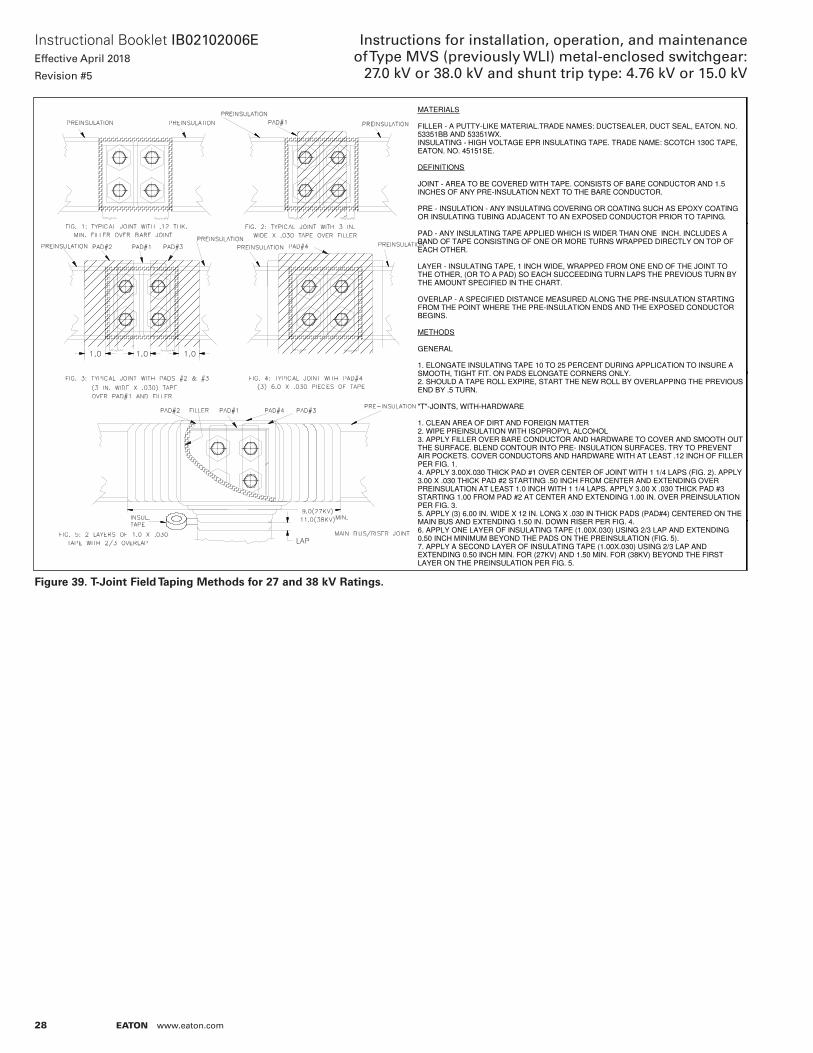
28
Instructional Booklet IB02102006EEffective April 2018
Revision #5
Instructions for installation, operation, and maintenance of Type MVS (previously WLI) metal-enclosed switchgear:
27.0 kV or 38.0 kV and shunt trip type: 4.76 kV or 15.0 kV
EATON www.eaton.com
Figure 39. T-Joint Field Taping Methods for 27 and 38 kV Ratings.
DRAFTER MODEL FILENAME
ENGINEER
MFG. ENG.
NEXT ASSY
TOOL REF.
REFERENCE
SHOP/GENERAL ORDER NO.
ENGINEERING CHANGE NOTICE NO.
UNLESS SPECIFIED TOLERANCES PER
THIS DOCUMENT, INCLUDING THE DRAWING AND INFORMATION CONTAINED THEREON, IS CONFIDENTIAL AND IS THE EXCLUSIVE PROPERTY OF EATON CORPORATION, AND IS MERELY ON LOAN AND SUBJECT TO RECALL BY EATON CORPORATION AT ANY TIME.BY TAKING POSSESSION OF THIS DOCUMENT, THE RECIPIENT ACKNOWLEDGES AND AGREES THAT THIS DOCUMENT CANNOT BE USED IN ANY MANNER ADVERSE TO THE INTERESTS OF EATON, AND THAT NO PORTION OF THIS DOCUMENT MAY BE COPIED OR OTHERWISE REPRODUCED WITHOUT THE PRIOR WRITTEN CONSENT OF EATON CORPORATION. IN THE CASE OF CONFLICTING CONTRACTUAL PROVISIONS, THIS NOTICE SHALL GOVERN THE STATUS OF THIS DOCUMENT.
EATON CORPORATION - CONFIDENTIAL AND PROPRIETARYDATE
DATE
DATE
MODEL REV
SCALE PROJECT NO.
PRODUCT
DWG NO.
PARTS LIST REVTITLE BLOCK REV - 4
TITLE
SHEET OF
THIRD ANGLEPROJECTION
C
1 2
P. KIM
4/10/1991
NTS
7819C90
47819C90
VC-W SWGR27KV & 38KV JOINT TAPING
DIM
ENSI
ON
S TO
BE
INTE
RP
RET
ED
AS
ME
Y1
4.5
M -
19
94
IN A
CC
OR
DAN
CE
WIT
H
RE
VIS
ION
H
IST
OR
Y1
MATERIALS FILLER - A PUTTY-LIKE MATERIAL.TRADE NAMES: DUCTSEALER, DUCT SEAL, EATON. NO. 53351BB AND 53351WX.INSULATING - HIGH VOLTAGE EPR INSULATING TAPE. TRADE NAME: SCOTCH 130C TAPE, EATON. NO. 45151SE. DEFINITIONS JOINT - AREA TO BE COVERED WITH TAPE. CONSISTS OF BARE CONDUCTOR AND 1.5 INCHES OF ANY PRE-INSULATION NEXT TO THE BARE CONDUCTOR. PRE - INSULATION - ANY INSULATING COVERING OR COATING SUCH AS EPOXY COATING OR INSULATING TUBING ADJACENT TO AN EXPOSED CONDUCTOR PRIOR TO TAPING. PAD - ANY INSULATING TAPE APPLIED WHICH IS WIDER THAN ONE INCH. INCLUDES A BAND OF TAPE CONSISTING OF ONE OR MORE TURNS WRAPPED DIRECTLY ON TOP OF EACH OTHER. LAYER - INSULATING TAPE, 1 INCH WIDE, WRAPPED FROM ONE END OF THE JOINT TO THE OTHER, (OR TO A PAD) SO EACH SUCCEEDING TURN LAPS THE PREVIOUS TURN BY THE AMOUNT SPECIFIED IN THE CHART. OVERLAP - A SPECIFIED DISTANCE MEASURED ALONG THE PRE-INSULATION STARTING FROM THE POINT WHERE THE PRE-INSULATION ENDS AND THE EXPOSED CONDUCTOR BEGINS. METHODS GENERAL 1. ELONGATE INSULATING TAPE 10 TO 25 PERCENT DURING APPLICATION TO INSURE A SMOOTH, TIGHT FIT. ON PADS ELONGATE CORNERS ONLY.2. SHOULD A TAPE ROLL EXPIRE, START THE NEW ROLL BY OVERLAPPING THE PREVIOUSEND BY .5 TURN. "T"-JOINTS, WITH-HARDWARE 1. CLEAN AREA OF DIRT AND FOREIGN MATTER2. WIPE PREINSULATION WITH ISOPROPYL ALCOHOL3. APPLY FILLER OVER BARE CONDUCTOR AND HARDWARE TO COVER AND SMOOTH OUTTHE SURFACE. BLEND CONTOUR INTO PRE- INSULATION SURFACES. TRY TO PREVENT AIR POCKETS. COVER CONDUCTORS AND HARDWARE WITH AT LEAST .12 INCH OF FILLERPER FIG. 1.4. APPLY 3.00X.030 THICK PAD #1 OVER CENTER OF JOINT WITH 1 1/4 LAPS (FIG. 2). APPLY 3.00 X .030 THICK PAD #2 STARTING .50 INCH FROM CENTER AND EXTENDING OVER PREINSULATION AT LEAST 1.0 INCH WITH 1 1/4 LAPS. APPLY 3.00 X .030 THICK PAD #3 STARTING 1.00 FROM PAD #2 AT CENTER AND EXTENDING 1.00 IN. OVER PREINSULATION PER FIG. 3.5. APPLY (3) 6.00 IN. WIDE X 12 IN. LONG X .030 IN THICK PADS (PAD#4) CENTERED ON THE MAIN BUS AND EXTENDING 1.50 IN. DOWN RISER PER FIG. 4.6. APPLY ONE LAYER OF INSULATING TAPE (1.00X.030) USING 2/3 LAP AND EXTENDING 0.50 INCH MINIMUM BEYOND THE PADS ON THE PREINSULATION (FIG. 5).7. APPLY A SECOND LAYER OF INSULATING TAPE (1.00X.030) USING 2/3 LAP AND EXTENDING 0.50 INCH MIN. FOR (27KV) AND 1.50 MIN. FOR (38KV) BEYOND THE FIRST LAYER ON THE PREINSULATION PER FIG. 5.
2R
N-Q
H1
51
9
D.P
AL
MIE
RI 7
/23
/19
96
ZO
NE
A3
9.0
(27
KV
) A
ND
11.0
(38
KV
) M
IN.W
AS
9
.0.
TIT
LE
WA
S V
C-W
JO
INT
TA
PIN
G.
ON
SH
.2,
SA
ME
CH
AN
GE
S
AP
PL
Y.
3G
MV
A-1
73
3
TA
YL
OR
10
/19
/07
UP
DA
TE
D D
WG
. N
OT
E
CH
AN
GE
S:
FR
OM
F
LU
IDZ
. T
O
PR
EIN
SU
LA
TIO
N.
4E
CO
-09
72
72
SID
3
/22
/20
16
J. R
OB
INS
ON
3
/22
/20
16
RE
DR
AW
N T
O
INV
EN
TO
RS
HE
ET
2 -
RE
MO
VE
D
JO
INT
S,
WIT
H
CA
BL
E/B
OO
T
CO
NN
EC
TIO
NS
IN
FO

29
Instructional Booklet IB02102006EEffective April 2018
Revision #5
Instructions for installation, operation, and maintenance of Type MVS (previously WLI) metal-enclosed switchgear: 27.0 kV or 38.0 kV and shunt trip type: 4.76 kV or 15.0 kV
EATON www.eaton.com
Figure 40. Thru-joint Field Taping Methods for 27 and 38 kV Ratings.
DWG NO
MODEL REV
SHEET OF
TITLE
ALL REV. NOTES LISTED ON SHT. 1
REVMODEL FILENAMET.BLKREV-4C
7819C90
2 2 4
JOINT TAPING
THRU-JOINTS, WITH-HARDWARE1. CLEAN AREA OF DIRT AND FOREIGN MATTER2. WIPE PREINSULATION WITH ISOPROPYL ALCOHOL.3. APPLY FILLER OVER BARE CONDUCTOR AND HARDWARE TO COVER AND SMOOTH OUT THE SURFACE. BLEND CONTOUR INTO PRE- INSULATION SURFACES. TRY TO PREVENT AIR POCKETS. COVER CONDUCTORS AND HARDWARE WITH AT LEAST .12 INCH OF FILLER PER FIG. 6.4. APPLY 3.0X.030 THICK PAD #1 OVER CENTER OF JOINT WITH 11/4 LAPS (FIG.7).5. APPLY 3.0X.030 THICK PAD #2 STARTING .50 INCH FROM CENTER AND EXTENDING OVER PREINSULATION AT LEAST 1.0 INCH WITH 1 1/4 LAPS. APPLY 3.00 X .030 THICK PAD #3 STARTING 1.00 FROM PAD #2 AT CENTER AND EXTENDING 1.00 IN. OVER PREINSULATION PER FIG. 8.6. APPLY ONE LAYER OF INSULATING TAPE (1.00X.030) USING 2/3 LAP AND EXTENDING 0.50 INCH MINIMUM BEYOND THE PADSON THE PREINSULATION PER FIG. 9.7. APPLY A SECOND LAYER OF INSULATING TAPE (1.00X.030) USING 2/3 LAP AND EXTENDING 0.50 INCH MINIMUM BEYOND THE FIRST LAYER ON THE PREINSULATION PER FIG. 9.

30
Instructional Booklet IB02102006EEffective April 2018
Revision #5
Instructions for installation, operation, and maintenance of Type MVS (previously WLI) metal-enclosed switchgear:
27.0 kV or 38.0 kV and shunt trip type: 4.76 kV or 15.0 kV
EATON www.eaton.com
Figure 41. Zero Sequence Current Transformer Connections.
All connections to ground (Such as shielding)must be carried through the current transformerand solidly grounded on the load side of the CTas shown. Use #6 wire with 600V insulation.
Lead, armor, conduit, and so on
To Load
Cable connections to switchgear terminalswhen used with Zero Sequence Transformers
Insulated pothead bushing
Pothead ground lead must be carriedthrough the Zero Sequence currenttransformer and solidly grounded on the load side of the ct as shown. Use #6 wire with 600V insulation.
Power Cables
Conduit, when used
Cable connections to switchgear terminalswhen used with Insulated Pothead.
Conduit must be terminated andsolidly grounded on the load sideof the current transformer.
Zero Sequence transformer
Electrical joint required betweenpothead and lead covered or armoredpower cables.
Insulated pothead mounting
Lead, armor, conduit, Interstice ground conductors, and so on. Must be terminated and solidly groundedon the load side of the current transformer.
Zero Sequence Transformer
Power Cables
Switchgear Terminals
To Load

31
Instructional Booklet IB02102006EEffective April 2018
Revision #5
Instructions for installation, operation, and maintenance of Type MVS (previously WLI) metal-enclosed switchgear: 27.0 kV or 38.0 kV and shunt trip type: 4.76 kV or 15.0 kV
EATON www.eaton.com
otese:N

Eaton1000 Eaton BoulevardCleveland, OH 44122United StatesEaton.com
© 2018 EatonAll Rights ReservedPrinted in USAPublication No. IB02102006E / TBG001312April 2018
Eaton is a registered trademark.
All other trademarks are property of their respective owners.
Instructional Booklet IB02102006EEffective April 2018
Revision #5
Instructions for installation, operation, and maintenance of Type MVS (previously WLI) metal-enclosed switchgear:
27.0 kV or 38.0 kV and shunt trip type: 4.76 kV or 15.0 kV