instruction manual vito interface and average … manual vito page 1 instruction manual vito...
TRANSCRIPT
Instruction manual VITO interface and average temperature (and water) probes for 854 servo, 97x SmartRadar and 877 FDI

_________________________________________________________________________
Instruction manual VITO Page 1
Instruction manual VITO interface and average temperature (and water) probes for 854 servo, 97x SmartRadar and 877 FDI April 2013 Part no.: 4416.655 Revision 6
Enraf B.V. P.O. Box 812 2600 AV Delft Netherlands Tel. : +31 15 2701100 Fax : +31 15 2701111 E-mail : [email protected] Website : http://www.honeywellenraf.com
___________________________________________________________________________
Instruction manual VITO Page 2
Copyright 2006 - 2013 Enraf B.V. All rights reserved Reproduction in any form without the prior consent of Enraf B.V. is not allowed. This manual is for information only. The contents, descriptions and specifications are subject to change without notice. Enraf B.V. accepts no responsibility for any errors that may appear in this manual. The warranty terms and conditions applicable in the country of purchase in respect to Enraf B.V. products are available from your supplier. Please retain them with your proof of purchase.
___________________________________________________________________________
Instruction manual VITO Page 3
Preface This manual is intended for technicians involved with the commissioning and service of average temperature probes, connected via the Honeywell Enraf 762 VITO Interface unit to 854 servo level gauges, the 97x SmartRadar level gauges or the 877 Field Display & Interface. A description preceding the technical procedures gives the technical information necessary to understand its functioning. It is recommended to read this description prior to performing any of the procedures. Safety and prevention of damage Refer to the chapter Safety in the instruction manual of the applicable instrument (servo/radar gauge or indicator) for detailed safety instructions. “Warnings”, “Cautions”, and Notes have been used throughout this manual to bring special matters to the immediate attention of the reader.
• A Warning concerns danger to the safety of the technician or user; • A Caution draws attention to an action which may damage the equipment; • A Note points out a statement deserving more emphasis than the general text, but does not deserve a
“Warning” or a “Caution”. The sequence of steps in a procedure may also be important from the point of view of personal safety and prevention of damage; it is therefore advised not to change the sequence of procedure steps or alter a procedure. Legal aspects The commissioning and trouble shooting to the instrument may only be conducted by qualified engineers, trained by Honeywell Enraf and with knowledge of safety regulations for working in hazardous areas. The information in this manual is the copyright property of Enraf B.V., Netherlands. Enraf B.V. disclaims any responsibility for personal injury or damage to equipment caused by :
• Deviation from any of the prescribed procedures; • Execution of activities that are not prescribed; • Neglect of the general safety precautions for handling tools and use of electricity.
EC declaration of conformity The Honeywell Enraf instrument is in conformity with the protection requirements of EC Council Directive 89/336/EC. Refer to EC declaration of conformity delivered with the instrument or to the installation guide of the instrument. Additional information Please do not hesitate to contact Honeywell Enraf or its representative if you require any additional information.
___________________________________________________________________________
Instruction manual VITO Page 4
Table of Contents
Preface ...................................................................................................................................... 3
1 Introduction VITO Interface and average temperature probes ..................................... 6
2 Average temperature measurement with VITO temperature probes ........................... 8
2.1 Introduction VITO temperature probes .................................................................................................... 8
2.2 Commissioning of VITO temperature probe ............................................................................................ 9
2.2.1 Average temperature settings ................................................................................................................ 10
2.2.2 Additional temperature settings for 877 FDI........................................................................................... 14
2.2.3 Temperature verification VITO probes ................................................................................................... 15
2.3 Operation ................................................................................................................................................... 16
2.3.1 Display .................................................................................................................................................... 16
2.3.2 Data items .............................................................................................................................................. 16
2.4 Troubleshooting ....................................................................................................................................... 17
2.4.1 Temperature error request (item EM) .................................................................................................... 17
2.4.2 Temperature status request (item MQ) .................................................................................................. 17
2.4.3 Temperature pointer (items VP and VV) ................................................................................................ 18
3 Average temperature measurement with MRT............................................................. 20
3.1 Introduction MRT ...................................................................................................................................... 20
3.2 Commissioning of Multiple Resistance Thermometer ......................................................................... 21
3.2.1 Temperature related settings ................................................................................................................. 21
3.2.2 Additional settings for and 877 FDI ........................................................................................................ 23
3.2.3 Temperature verification MRT probes .................................................................................................... 23
3.3 Operation ................................................................................................................................................... 24
3.3.1 Display ................................................................................................................................................... 24
3.3.2 Data items .............................................................................................................................................. 24
3.4 Troubleshooting ....................................................................................................................................... 25
3.4.1 Temperature error request HCU/HPI (item EM)..................................................................................... 25
3.4.2 Temperature status request (item MQ) .................................................................................................. 25
3.4.3 Temperature pointer (items VP and VV) ................................................................................................ 26
4 Average temperature measurement with MPT / RTD .................................................. 27
4.1 Introduction MPT / RTD ............................................................................................................................ 27
4.2 Commissioning of MPT / RTD ................................................................................................................. 27
4.2.1 Temperature related settings ................................................................................................................. 27
4.2.2 Additional settings for and 877 FDI ........................................................................................................ 31
4.2.3 Temperature verification MPT probes .................................................................................................... 31
4.3 Operation ................................................................................................................................................... 32
4.3.1 Display ................................................................................................................................................... 32
4.3.2 Data items ............................................................................................................................................. 32
___________________________________________________________________________
Instruction manual VITO Page 5
4.4 Troubleshooting ....................................................................................................................................... 33
4.4.1 Temperature error (item EM).................................................................................................................. 33
4.4.2 Temperature status request (item MQ) .................................................................................................. 33
4.4.3 Temperature pointer (items VP and VV) ................................................................................................ 34
5 Water bottom measurement .......................................................................................... 35
5.1 Introduction water bottom measurement............................................................................................... 35
5.1.1 Water probe versions ............................................................................................................................. 35
5.1.2 Principle of measurement....................................................................................................................... 36
5.2 Commissioning of water bottom probe.................................................................................................. 36
5.2.1 Commissioning measurements .............................................................................................................. 36
5.2.2 Water probe settings ............................................................................................................................ 39
5.3 Operation ................................................................................................................................................... 40
5.3.1 Display .................................................................................................................................................... 40
5.3.2 Water above / below probe warning ....................................................................................................... 40
5.3.3 Data items .............................................................................................................................................. 40
5.4 Troubleshooting ....................................................................................................................................... 41
5.4.1 Water error request (item EW) ............................................................................................................... 41
5.4.2 Water level (ullage) status bytes ............................................................................................................ 41
5.4.3 Water bottom pointer (items VP and VV) ............................................................................................... 42
Appendix A ASCII table ..................................................................................................... 43
Appendix B Configuration procedure for 765/766/768 VITO water probe .................... 44
Appendix C Average product temperature verification procedure ............................... 47
Appendix D Part numbers ................................................................................................ 48
Appendix E Related documents ....................................................................................... 49
Introduction VITO Interface and average temperature probes ___________________________________________________________________________
Instruction manual VITO Page 6
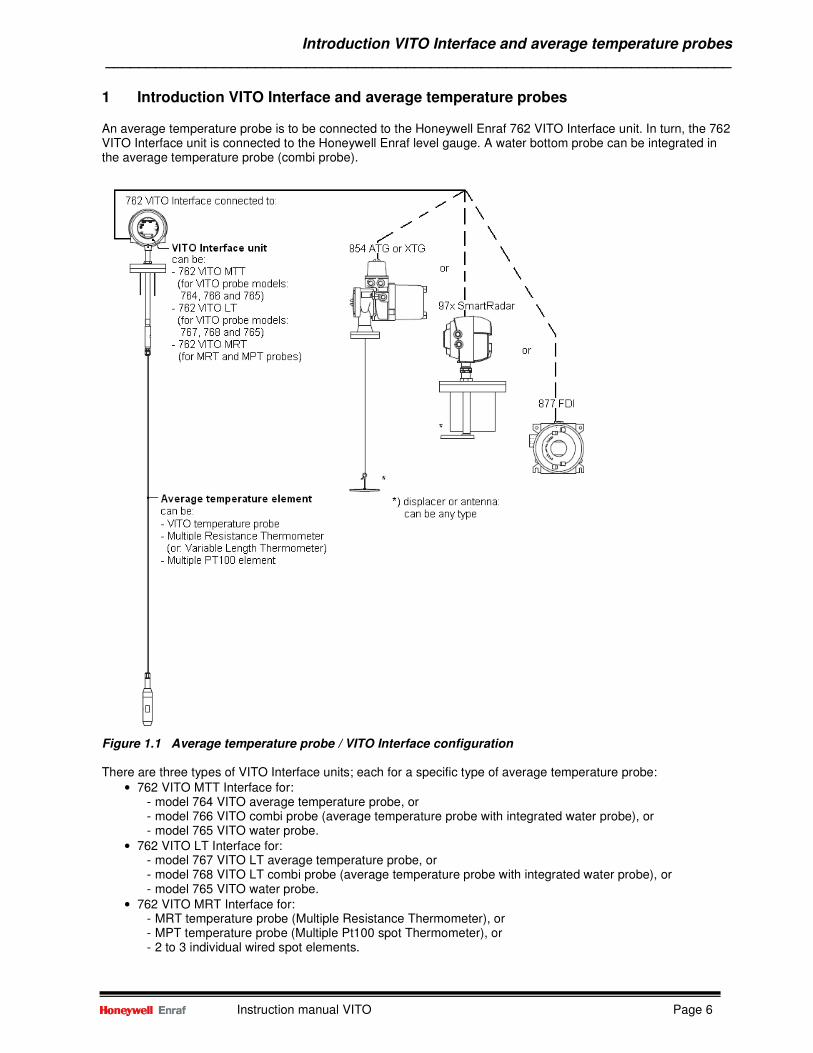
1 Introduction VITO Interface and average temperature probes An average temperature probe is to be connected to the Honeywell Enraf 762 VITO Interface unit. In turn, the 762 VITO Interface unit is connected to the Honeywell Enraf level gauge. A water bottom probe can be integrated in the average temperature probe (combi probe).
Figure 1.1 Average temperature probe / VITO Interface configuration There are three types of VITO Interface units; each for a specific type of average temperature probe:
• 762 VITO MTT Interface for: - model 764 VITO average temperature probe, or - model 766 VITO combi probe (average temperature probe with integrated water probe), or - model 765 VITO water probe.
• 762 VITO LT Interface for: - model 767 VITO LT average temperature probe, or - model 768 VITO LT combi probe (average temperature probe with integrated water probe), or - model 765 VITO water probe.
• 762 VITO MRT Interface for: - MRT temperature probe (Multiple Resistance Thermometer), or - MPT temperature probe (Multiple Pt100 spot Thermometer), or - 2 to 3 individual wired spot elements.
Introduction VITO Interface and average temperature probes ___________________________________________________________________________
Instruction manual VITO Page 7
The 764 and 766 VITO temperature probes have 16 elements. These elements are thermocouples, and at the cold junction a highly accurate Pt100 resistor is located to measure the absolute temperature. The 767 and 768 VITO LT temperature probes are similar to the 764 and 766 temperature probes, but only have 9 elements. An MRT (Multiple Resistance Thermometer) or Variable Length Thermometer comprises a number of resistance elements of different lengths, all starting close to the bottom end of the temperature probe. An MPT probe (Multiple Pt100 spots) consisting of 1 through 14 RTD's with 2 common ground wires. More information about the different temperature probes can be found in the introduction section of chapters 2, 3 and 4. The Honeywell Enraf level gauge must be equipped with a suitable option board to receive the signal from the 762 VITO Interface:
• HCU option board for Honeywell Enraf 854 servo level gauges and 877 FDI; • ICU_HPI option board for Honeywell Enraf 97x SmartRadar level gauges • FII-VT board for Honeywell Enraf 990 SmartRadar FlexLine
This instruction manual describes the commissioning settings in conjunction with the Honeywell Enraf 854 servo level gauges, the 877 Field Display & Interface and the 97x SmartRadar level gauges. The commissioning of the different type of probes is divided over the following chapters:
• Average temperature with VITO (combi) probes: chapter 2 • Average temperature with MRT: chapter 3 • Average temperature with MPT or 2 – 3 spots: chapter 4 • Water bottom measurement: chapter 5
Refer to the Commissioning manual SmartRadar FlexLine for the average temperature commissioning and water bottom settings with the 990 SmartRadar FlexLine.
Average temperature measurement with VITO temperature probes ___________________________________________________________________________
Instruction manual VITO Page 8
2 Average temperature measurement with VITO temperature probes
2.1 Introduction VITO temperature probes Honeywell Enraf’s portfolio for average temperature measurement consists of the following probes:
• 764 VITO temperature probe; • 766 VITO water and temperature probe; • 767 VITO LT temperature probe; • 768 VITO LT water and temperature probe.
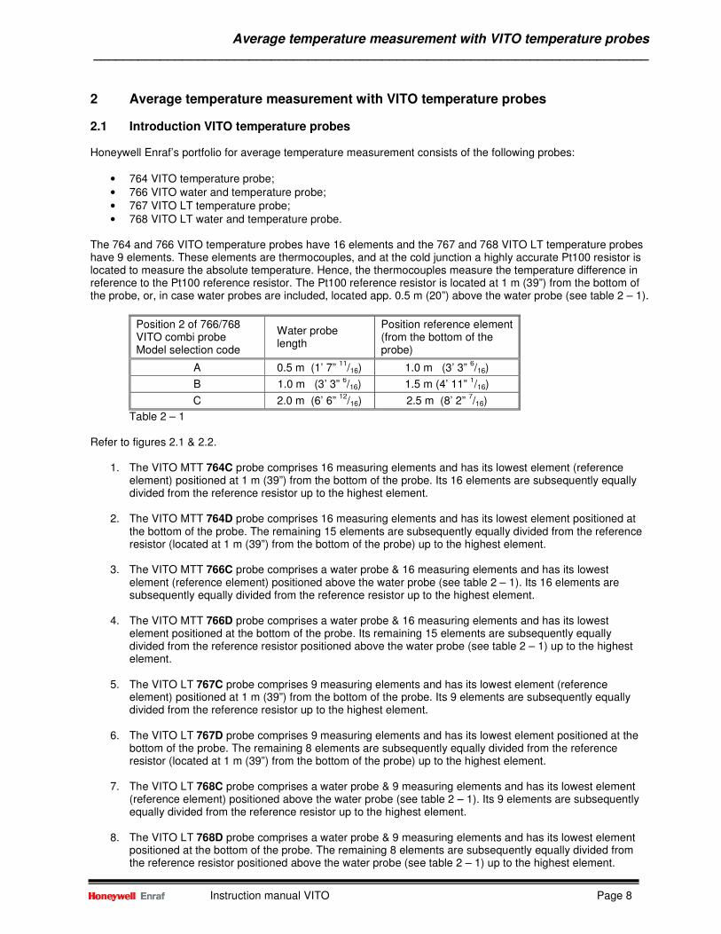
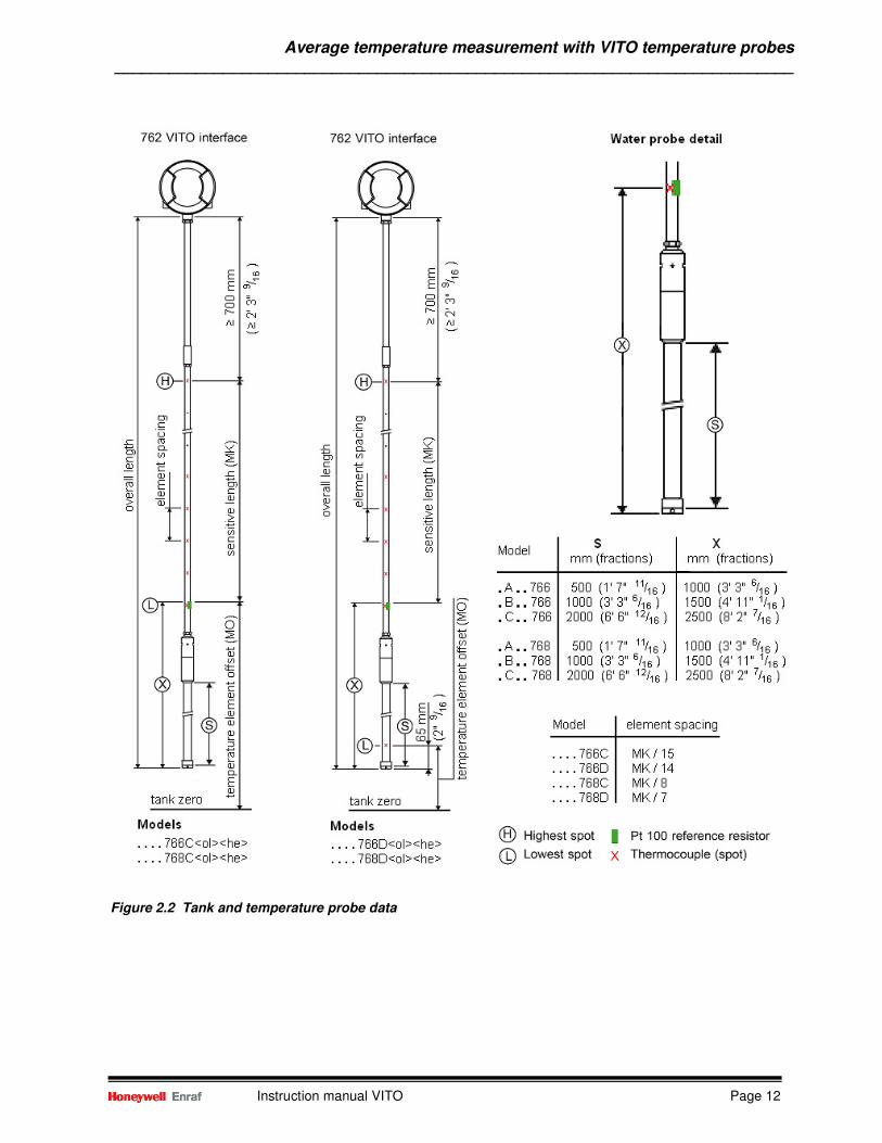
The 764 and 766 VITO temperature probes have 16 elements and the 767 and 768 VITO LT temperature probes have 9 elements. These elements are thermocouples, and at the cold junction a highly accurate Pt100 resistor is located to measure the absolute temperature. Hence, the thermocouples measure the temperature difference in reference to the Pt100 reference resistor. The Pt100 reference resistor is located at 1 m (39”) from the bottom of the probe, or, in case water probes are included, located app. 0.5 m (20”) above the water probe (see table 2 – 1).
Position 2 of 766/768 VITO combi probe Model selection code
Water probe length
Position reference element (from the bottom of the probe)
A 0.5 m (1’ 7” 11
/16) 1.0 m (3’ 3” 6/16)
B 1.0 m (3’ 3” 6/16) 1.5 m (4’ 11”
1/16)
C 2.0 m (6’ 6” 12
/16) 2.5 m (8’ 2” 7/16)
Table 2 – 1 Refer to figures 2.1 & 2.2.
1. The VITO MTT 764C probe comprises 16 measuring elements and has its lowest element (reference element) positioned at 1 m (39”) from the bottom of the probe. Its 16 elements are subsequently equally divided from the reference resistor up to the highest element.
2. The VITO MTT 764D probe comprises 16 measuring elements and has its lowest element positioned at
the bottom of the probe. The remaining 15 elements are subsequently equally divided from the reference resistor (located at 1 m (39”) from the bottom of the probe) up to the highest element.
3. The VITO MTT 766C probe comprises a water probe & 16 measuring elements and has its lowest element (reference element) positioned above the water probe (see table 2 – 1). Its 16 elements are subsequently equally divided from the reference resistor up to the highest element.
4. The VITO MTT 766D probe comprises a water probe & 16 measuring elements and has its lowest
element positioned at the bottom of the probe. Its remaining 15 elements are subsequently equally divided from the reference resistor positioned above the water probe (see table 2 – 1) up to the highest element.
5. The VITO LT 767C probe comprises 9 measuring elements and has its lowest element (reference
element) positioned at 1 m (39”) from the bottom of the probe. Its 9 elements are subsequently equally divided from the reference resistor up to the highest element.
6. The VITO LT 767D probe comprises 9 measuring elements and has its lowest element positioned at the
bottom of the probe. The remaining 8 elements are subsequently equally divided from the reference resistor (located at 1 m (39”) from the bottom of the probe) up to the highest element.
7. The VITO LT 768C probe comprises a water probe & 9 measuring elements and has its lowest element
(reference element) positioned above the water probe (see table 2 – 1). Its 9 elements are subsequently equally divided from the reference resistor up to the highest element.
8. The VITO LT 768D probe comprises a water probe & 9 measuring elements and has its lowest element
positioned at the bottom of the probe. The remaining 8 elements are subsequently equally divided from the reference resistor positioned above the water probe (see table 2 – 1) up to the highest element.
Average temperature measurement with VITO temperature probes ___________________________________________________________________________
Instruction manual VITO Page 9
Average product temperature is calculated from all submerged elements from the reference element and higher located elements. Before an element is used in the average product temperature calculation, it must be submerged by a certain amount of product, specified by item MP (product immersion depth; default 0.5 m (20”)). According to the international recommendations (API and ISO) for temperature measurement in storage tanks, the lowest element shall be located 1 m (3 ft) from the bottom of the tank. The VITO probe models 764C, 766C, 767C and 768C fulfil this recommendation. The VITO probe models 764D, 766D, 767D and 768D also fulfil this recommendation, but have in addition one element at the bottom of the probe. By default, the lowest element at the bottom of the probe is not used for average product temperature calculations. Only when the level is such low that the reference element is not selected anymore for average product temperature calculation, the lowest element is used as average product temperature but with a special temperature status (level below lowest element). That will be shown on the tank gauging system as a temperature with reduced accuracy. By means of a ‘switch’ (item MJ) one can also enable the lowest element close to the bottom of the probe for average product temperature calculation. For the combi probes (water & temperature probes models 766D and 768D) an additional condition is that the lowest element is only used when no water is detected. Note: When the lowest element close to the bottom of the probe is enabled for average temperature calculation, the temperature measurement system is not operating according the international recommendations.
2.2 Commissioning of VITO temperature probe The commissioning of the optional average temperature part should be performed after the basic commissioning of the level gauge or indicator.
Average temperature measurement with VITO temperature probes ___________________________________________________________________________
Instruction manual VITO Page 10
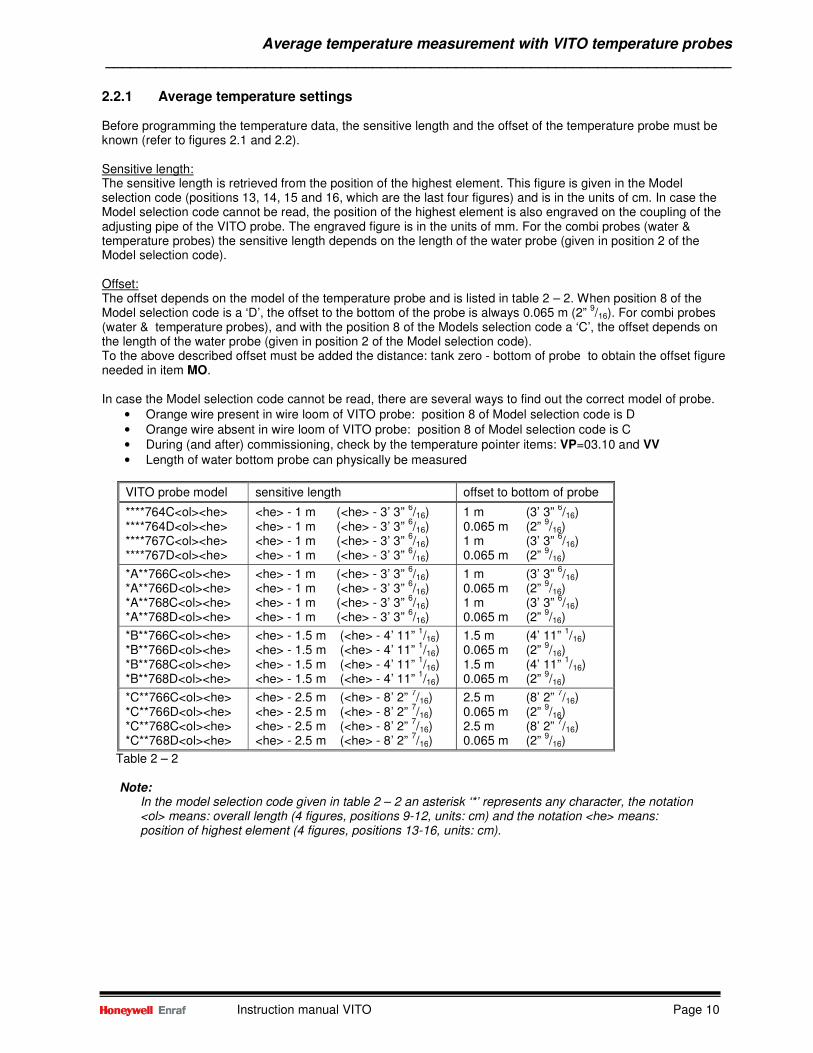
2.2.1 Average temperature settings Before programming the temperature data, the sensitive length and the offset of the temperature probe must be known (refer to figures 2.1 and 2.2). Sensitive length: The sensitive length is retrieved from the position of the highest element. This figure is given in the Model selection code (positions 13, 14, 15 and 16, which are the last four figures) and is in the units of cm. In case the Model selection code cannot be read, the position of the highest element is also engraved on the coupling of the adjusting pipe of the VITO probe. The engraved figure is in the units of mm. For the combi probes (water & temperature probes) the sensitive length depends on the length of the water probe (given in position 2 of the Model selection code). Offset: The offset depends on the model of the temperature probe and is listed in table 2 – 2. When position 8 of the Model selection code is a ‘D’, the offset to the bottom of the probe is always 0.065 m (2”
9/16). For combi probes
(water & temperature probes), and with the position 8 of the Models selection code a ‘C’, the offset depends on the length of the water probe (given in position 2 of the Model selection code). To the above described offset must be added the distance: tank zero - bottom of probe to obtain the offset figure needed in item MO. In case the Model selection code cannot be read, there are several ways to find out the correct model of probe.
• Orange wire present in wire loom of VITO probe: position 8 of Model selection code is D • Orange wire absent in wire loom of VITO probe: position 8 of Model selection code is C • During (and after) commissioning, check by the temperature pointer items: VP=03.10 and VV • Length of water bottom probe can physically be measured
VITO probe model sensitive length offset to bottom of probe
****764C<ol><he> ****764D<ol><he> ****767C<ol><he> ****767D<ol><he>
<he> - 1 m (<he> - 3’ 3” 6/16)
<he> - 1 m (<he> - 3’ 3” 6/16)
<he> - 1 m (<he> - 3’ 3” 6/16)
<he> - 1 m (<he> - 3’ 3” 6/16)
1 m (3’ 3” 6/16)
0.065 m (2” 9/16)
1 m (3’ 3” 6/16)
0.065 m (2” 9/16)
*A**766C<ol><he> *A**766D<ol><he> *A**768C<ol><he> *A**768D<ol><he>
<he> - 1 m (<he> - 3’ 3” 6/16)
<he> - 1 m (<he> - 3’ 3” 6/16)
<he> - 1 m (<he> - 3’ 3” 6/16)
<he> - 1 m (<he> - 3’ 3” 6/16)
1 m (3’ 3” 6/16)
0.065 m (2” 9/16)
1 m (3’ 3” 6/16)
0.065 m (2” 9/16)
*B**766C<ol><he> *B**766D<ol><he> *B**768C<ol><he> *B**768D<ol><he>
<he> - 1.5 m (<he> - 4’ 11” 1/16)
<he> - 1.5 m (<he> - 4’ 11” 1/16)
<he> - 1.5 m (<he> - 4’ 11” 1/16)
<he> - 1.5 m (<he> - 4’ 11” 1/16)
1.5 m (4’ 11” 1/16)
0.065 m (2” 9/16)
1.5 m (4’ 11” 1/16)
0.065 m (2” 9/16)
*C**766C<ol><he> *C**766D<ol><he> *C**768C<ol><he> *C**768D<ol><he>
<he> - 2.5 m (<he> - 8’ 2” 7/16)
<he> - 2.5 m (<he> - 8’ 2” 7/16)
<he> - 2.5 m (<he> - 8’ 2” 7/16)
<he> - 2.5 m (<he> - 8’ 2” 7/16)
2.5 m (8’ 2” 7/16)
0.065 m (2” 9/16)
2.5 m (8’ 2” 7/16)
0.065 m (2” 9/16)
Table 2 – 2
Note: In the model selection code given in table 2 – 2 an asterisk ‘*’ represents any character, the notation <ol> means: overall length (4 figures, positions 9-12, units: cm) and the notation <he> means: position of highest element (4 figures, positions 13-16, units: cm).
Average temperature measurement with VITO temperature probes ___________________________________________________________________________
Instruction manual VITO Page 11
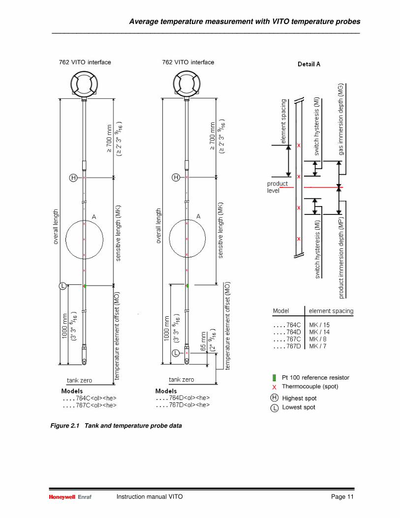
Figure 2.1 Tank and temperature probe data
Average temperature measurement with VITO temperature probes ___________________________________________________________________________
Instruction manual VITO Page 12
Figure 2.2 Tank and temperature probe data
Average temperature measurement with VITO temperature probes ___________________________________________________________________________
Instruction manual VITO Page 13
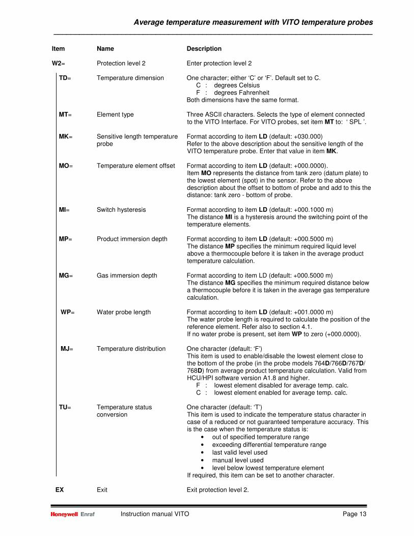
Item Name Description W2= Protection level 2 Enter protection level 2 TD= Temperature dimension One character; either ‘C’ or ‘F’. Default set to C.
C : degrees Celsius F : degrees Fahrenheit
Both dimensions have the same format. MT= Element type Three ASCII characters. Selects the type of element connected
to the VITO Interface. For VITO probes, set item MT to: ‘ SPL ’. MK= Sensitive length temperature Format according to item LD (default: +030.000) probe Refer to the above description about the sensitive length of the
VITO temperature probe. Enter that value in item MK. MO= Temperature element offset Format according to item LD (default: +000.0000).
Item MO represents the distance from tank zero (datum plate) to the lowest element (spot) in the sensor. Refer to the above description about the offset to bottom of probe and add to this the distance: tank zero - bottom of probe.
MI= Switch hysteresis Format according to item LD (default: +000.1000 m)
The distance MI is a hysteresis around the switching point of the temperature elements.
MP= Product immersion depth Format according to item LD (default: +000.5000 m)
The distance MP specifies the minimum required liquid level above a thermocouple before it is taken in the average product temperature calculation.
MG= Gas immersion depth Format according to item LD (default: +000.5000 m)
The distance MG specifies the minimum required distance below a thermocouple before it is taken in the average gas temperature calculation.
WP= Water probe length Format according to item LD (default: +001.0000 m) The water probe length is required to calculate the position of the reference element. Refer also to section 4.1. If no water probe is present, set item WP to zero (+000.0000).
MJ= Temperature distribution One character (default: ‘F’) This item is used to enable/disable the lowest element close to the bottom of the probe (in the probe models 764D/766D/767D/ 768D) from average product temperature calculation. Valid from HCU/HPI software version A1.8 and higher. F : lowest element disabled for average temp. calc. C : lowest element enabled for average temp. calc.
TU= Temperature status One character (default: ‘T’)
conversion This item is used to indicate the temperature status character in case of a reduced or not guaranteed temperature accuracy. This is the case when the temperature status is:
• out of specified temperature range • exceeding differential temperature range • last valid level used • manual level used • level below lowest temperature element
If required, this item can be set to another character. EX Exit Exit protection level 2.
Average temperature measurement with VITO temperature probes ___________________________________________________________________________
Instruction manual VITO Page 14
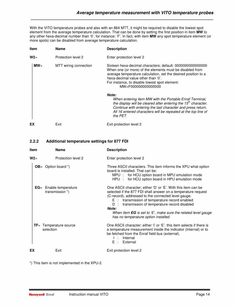
With the VITO temperature probes and also with an 864 MTT, it might be required to disable the lowest spot element from the average temperature calculation. That can be done by setting the first position in item MW to any other hexa-decimal number than ‘0’, for instance: ‘F’. In fact, with item MW any spot temperature element (or more spots) can be disabled from average temperature calculation. Item Name Description W2= Protection level 2 Enter protection level 2 MW= MTT wiring connection Sixteen hexa-decimal characters; default: 0000000000000000 When one (or more) of the elements must be disabled from
average temperature calculation, set the desired position to a hexa-decimal value other than ‘0’.
For instance, to disable lowest spot element: MW=F000000000000000 Note: When entering item MW with the Portable Enraf Terminal, the display will be cleared after entering the 15
th character.
Continue with entering the last character and press return. All 16 entered characters will be repeated at the top line of the PET. EX Exit Exit protection level 2
2.2.2 Additional temperature settings for 877 FDI Item Name Description W2= Protection level 2 Enter protection level 2
OB= Option board *) Three ASCII characters. This item informs the XPU what option board is installed. That can be:
MPU : for HCU option board in MPU emulation mode HPU : for HCU option board in HPU emulation mode
EG= Enable temperature One ASCII character; either ‘D’ or ‘E’. With this item can be
transmission *) selected if the 877 FDI shall answer on a temperature request (C-record), addressed to the connected level gauge.
E : transmission of temperature record enabled D : transmission of temperature record disabled
Note: When item EG is set to ‘E’, make sure the related level gauge has no temperature option installed.
TF= Temperature source One ASCII character; either ‘I’ or ‘E’. this item selects if there is selection a temperature measurement inside the indicator (internal) or to be fetched from the Enraf field bus (external).
I : Internal E : External
EX Exit Exit protection level 2 *) This item is not implemented in the XPU-2.
Average temperature measurement with VITO temperature probes ___________________________________________________________________________
Instruction manual VITO Page 15
2.2.3 Temperature verification VITO probes After the settings described in section 2.2.1 and, if applicable in section 2.2.2, are entered the temperature measurement is operational. The following checks can be made to verify if the settings are made correct and the product temperature reading is correct.
• Read item AP (Average Product temperature): This data item is preceded by four status characters. The first status character is a hexa-decimal number, indicating the highest selected element for average product temperature calculation. This can be judged, on basis of the product level, and with the items U0 – UF (calculated spot positions), item MO (temperature element offset), item MP (product immersion depth) and item MI (switch hysteresis).
Refer to Detail A in figure 2.1: A spot element will be used in the average product temperature calculation if its position is below the actual level minus the product immersion depth. A spot element won’t be used in the average product temperature calculation if it is above the actual level minus the product immersion depth plus the switch hysteresis.
• Verify the average product temperature by manual measurement:
Refer to Appendix C for the procedure to verify the average product temperature reading by using a portable electronic thermometer.
Average temperature measurement with VITO temperature probes ___________________________________________________________________________
Instruction manual VITO Page 16
2.3 Operation
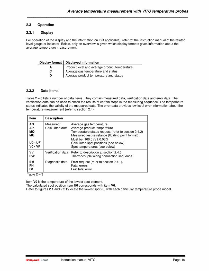
2.3.1 Display For operation of the display and the information on it (if applicable), refer tot the instruction manual of the related level gauge or indicator. Below, only an overview is given which display formats gives information about the average temperature measurement.
Display format Displayed information
A Product level and average product temperature
C Average gas temperature and status
D Average product temperature and status
2.3.2 Data items Table 2 – 3 lists a number of data items. They contain measured data, verification data and error data. The verification data can be used to check the results of certain steps in the measuring sequence. The temperature status indicates the validity of the measured data. The error data provides low level error information about the temperature measurement (refer to section 2.4).
Item Description
AG AP MQ MU U0 - UF V0 - VF
Measured/ Average gas temperature Calculated data Average product temperature Temperature status request (refer to section 2.4.2) Measured test resistance (floating point format);
Must be: 166.5 Ω ± 0.03% Calculated spot positions (see below) Spot temperatures (see below)
VV RW
Verification data Refer to description at section 2.4.3 Thermocouple wiring connection sequence
EM FH F0
Diagnostic data Error request (refer to section 2.4.1). Fatal errors Last fatal error
Table 2 – 3 Item V0 is the temperature of the lowest spot element. The calculated spot position item U0 corresponds with item V0. Refer to figures 2.1 and 2.2 to locate the lowest spot (L) with each particular temperature probe model.
Average temperature measurement with VITO temperature probes ___________________________________________________________________________
Instruction manual VITO Page 17
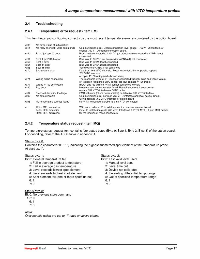
2.4 Troubleshooting
2.4.1 Temperature error request (item EM) This item helps you configuring correctly by the most recent temperature error encountered by the option board. xx00 No error, value at initialisation xx11 No reply on initial HART commands Communication error. Check connection level gauge – 762 VITO interface, or change 762 VITO interface or option board. xx50 Pt100 (or spot 0) error Brown wire connected to CN1 A-1 (or orange wire connected to CN2B-1) not connected . xx51 Spot 1 (or Pt100) error Blue wire to CN2B-1 (or brown wire to CN1A-1) not connected xx52 Spot 2 error Blue wire to CN2A-2 not connected xx64 Spot 14 error Blue wire to CN5A-2 not connected xx65 Spot 15 error Yellow wire to CN5A-1 not connected xx70 Sub-system error Data from 762 VITO not valid. Reset instrument; if error persist, replace
762 VITO interface or, open Pt100 wiring (red – brown wires) xx71 Wrong probe connection Thermocouple wires of VITO sensor connected wrongly (blue and yellow wires) or, isolation resistance VITO sensor too low (replace VITO probe) xx77 Wrong Pt100 connection Brown and red wires of VITO sensor connected wrongly xx80 Rtest error Measurement on test resistor failed. Reset instrument; if error persist replace 762 VITO interface or VITO probe xx84 Standard deviation too large EMC influence (check cable shields) or defective 762 VITO interface xx92 No data available Communication error between 762 VITO interface and level gauge. Check wiring; replace 762 VITO interface or option board. xx98 No temperature sources found No VITO temperature probe (and no RTD) connected xx: 22 for MPU emulation With error codes xx50 to xx65, connector numbers are mentioned 24 for HPU emulation Refer to Installation guide 762 VITO Interfaces & VITO, MTT, LT and MRT probes 30 for HCU emulation for the location of these connectors.
2.4.2 Temperature status request (item MQ) Temperature status request item contains four status bytes (Byte 0, Byte 1, Byte 2, Byte 3) of the option board. For decoding, refer to the ASCII table in appendix A. Status byte 0: Contains the characters ‘0’ ÷ ‘F’, indicating the highest submersed spot element of the temperature probe. At start up: ‘I’. Status byte 1: Status byte 2: Bit 0: General temperature fail Bit 0: Last valid level used 1: Fail in average product temperature 1: Manual level used 2: Fail in average gas temperature 2: Level time out 3: Level exceeds lowest spot element 3: Device not calibrated 4: Level exceeds highest spot element 4: Exceeding differential temp, range 5: Spot element fail (one or more spots defect) 5: Out of specified temperature range 6: 1 6: 1 7: 0 7: 0 Status byte 3: Bit 0: No previous store command 1-5: 0 6: 1 7: 0 Note: Only the bits which are set to ‘1’ have an active status.
Average temperature measurement with VITO temperature probes ___________________________________________________________________________
Instruction manual VITO Page 18
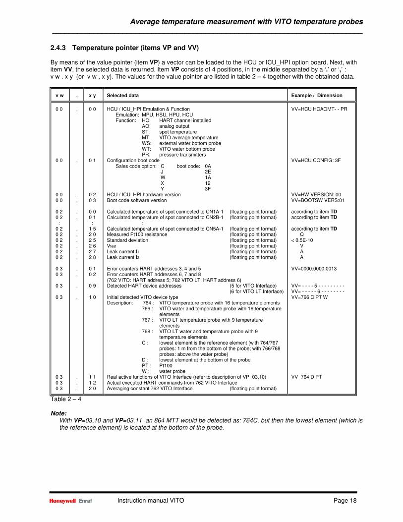
2.4.3 Temperature pointer (items VP and VV) By means of the value pointer (item VP) a vector can be loaded to the HCU or ICU_HPI option board. Next, with item VV, the selected data is returned. Item VP consists of 4 positions, in the middle separated by a ‘.’ or ‘,’ : v w . x y (or v w , x y). The values for the value pointer are listed in table 2 – 4 together with the obtained data.
v w
,
x y
Selected data
Example / Dimension
0 0 0 0 0 0 0 0 0 2 0 2 : 0 2 0 2 0 2 0 2 0 2 0 2 0 3 0 3 0 3 0 3 0 3 0 3 0 3
, , , , , , , , , , , , , , , , , , ,
0 0 0 1 0 2 0 3 0 0 0 1 : 1 5 2 0 2 5 2 6 2 7 2 8 0 1 0 2 0 9 1 0 1 1 1 2 2 0
HCU / ICU_HPI Emulation & Function
Emulation: MPU, HSU, HPU, HCU Function: HC: HART channel installed
AO: analog output ST: spot temperature MT: VITO average temperature WS: external water bottom probe WT: VITO water bottom probe PR: pressure transmitters
Configuration boot code Sales code option: C boot code: 0A
J 2E W 1A X 12 Y 3F
HCU / ICU_HPI hardware version Boot code software version Calculated temperature of spot connected to CN1A-1 (floating point format) Calculated temperature of spot connected to CN2B-1 (floating point format)
: Calculated temperature of spot connected to CN5A-1 (floating point format) Measured Pt100 resistance (floating point format) Standard deviation (floating point format) Vtest (floating point format) Leak current I1 (floating point format) Leak current I2 (floating point format) Error counters HART addresses 3, 4 and 5 Error counters HART addresses 6, 7 and 8 (762 VITO: HART address 5; 762 VITO LT: HART address 6) Detected HART device addresses (5 for VITO Interface) (6 for VITO LT Interface) Initial detected VITO device type Description: 764 : VITO temperature probe with 16 temperature elements
766 : VITO water and temperature probe with 16 temperature elements
767 : VITO LT temperature probe with 9 temperature elements
768 : VITO LT water and temperature probe with 9 temperature elements
C : lowest element is the reference element (with 764/767 probes: 1 m from the bottom of the probe; with 766/768 probes: above the water probe)
D : lowest element at the bottom of the probe PT : Pt100 W : water probe
Real active functions of VITO Interface (refer to description of VP=03,10) Actual executed HART commands from 762 VITO Interface Averaging constant 762 VITO Interface (floating point format)
VV=HCU HCAOMT- - PR VV=HCU CONFIG: 3F VV=HW VERSION: 00 VV=BOOTSW VERS:01 according to item TD according to item TD according to item TD
Ω < 0.5E-10
V A A
VV=0000:0000:0013 VV= - - - - 5 - - - - - - - - - VV= - - - - - 6 - - - - - - - - VV=766 C PT W VV=764 D PT
Table 2 – 4 Note:
With VP=03,10 and VP=03,11 an 864 MTT would be detected as: 764C, but then the lowest element (which is the reference element) is located at the bottom of the probe.
Average temperature measurement with VITO temperature probes ___________________________________________________________________________
Instruction manual VITO Page 19
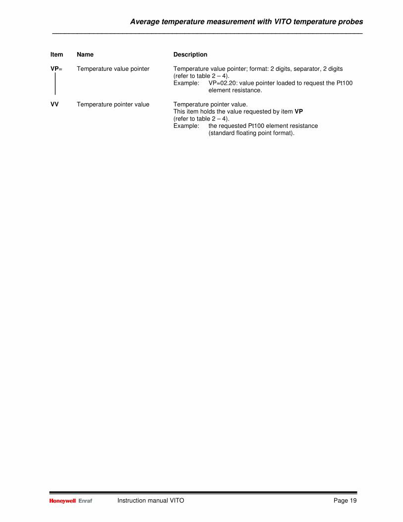
Item Name Description VP= Temperature value pointer Temperature value pointer; format: 2 digits, separator, 2 digits (refer to table 2 – 4).
Example: VP=02.20: value pointer loaded to request the Pt100 element resistance.
VV Temperature pointer value Temperature pointer value.
This item holds the value requested by item VP (refer to table 2 – 4). Example: the requested Pt100 element resistance
(standard floating point format).
Average temperature measurement with MRT ___________________________________________________________________________
Instruction manual VITO Page 20
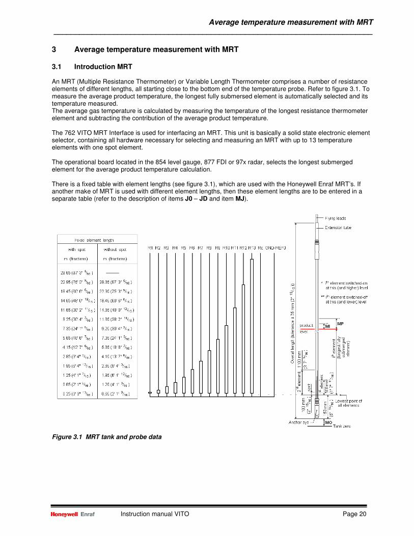
3 Average temperature measurement with MRT 3.1 Introduction MRT An MRT (Multiple Resistance Thermometer) or Variable Length Thermometer comprises a number of resistance elements of different lengths, all starting close to the bottom end of the temperature probe. Refer to figure 3.1. To measure the average product temperature, the longest fully submersed element is automatically selected and its temperature measured. The average gas temperature is calculated by measuring the temperature of the longest resistance thermometer element and subtracting the contribution of the average product temperature. The 762 VITO MRT Interface is used for interfacing an MRT. This unit is basically a solid state electronic element selector, containing all hardware necessary for selecting and measuring an MRT with up to 13 temperature elements with one spot element. The operational board located in the 854 level gauge, 877 FDI or 97x radar, selects the longest submerged element for the average product temperature calculation. There is a fixed table with element lengths (see figure 3.1), which are used with the Honeywell Enraf MRT’s. If another make of MRT is used with different element lengths, then these element lengths are to be entered in a separate table (refer to the description of items J0 – JD and item MJ).
Figure 3.1 MRT tank and probe data
Average temperature measurement with MRT ___________________________________________________________________________
Instruction manual VITO Page 21
3.2 Commissioning of Multiple Resistance Thermometer The commissioning of the optional average temperature part should be performed after the basic commissioning of the level gauge or indicator.
3.2.1 Temperature related settings Refer to figure 3.1 Item Name Description W2= Protection level 2 Enter protection level 2 TD= Temperature dimension One character; either ‘C’ or ‘F’. Default set to C.
C : degrees Celsius F : degrees Fahrenheit
Both dimensions have the same format. MJ= Multi temperature distribution One character; either ‘F’ or ‘T’. Default set to F.
This item determines whether fixed element positions are taken or configurable element positions via the items J0 .. JD. F : Fixed element positions (default) T : Configurable element positions (as per items J0 .. JD) The fixed element positions are described at section 3.3.2.
J0 – JD= MRT element position. Format according to item LD (default: +000.0000 m).
J0 through JD represent the distance from the end of the probe (nearest to tank zero level) to the MRT element if selected by item MJ.
MT= Element type Three ASCII characters (C3 C2 C1). Selects the element type connected to the 762 VITO MRT, with its characteristics. C3 R refers to an MRT without spot element Q refers to an MRT with spot element C2 C1 CB Rth = 90.2935 + T x 0.38826
range : -100 ÷ +250 °C (-148 ÷ +482 °F) CN Rth = 90.4778 + T x 0.38090
range : -100 ÷ +250 °C (-148 ÷ +482 °F) CS Rth = 90.5000 + T x 0.38730
range : -100 ÷ +250 °C (-148 ÷ +482 °F) where : Rth = resistance MRT element [Ω]
T = temperature MRT element [°C] PS *) Pt100 small range
range: -20 ÷ +120 °C (-4 ÷ +248 °F) PL *) Pt100 large range
range : -200 ÷ +250 °C (-328 ÷ +482 °F) NI *) Ni191 mid temp/tri temp range: -20 ÷ +120 °C (-4 ÷ +248 °F) *) From HCU/ICU_HPI software version A1.9 and higher MN= Number of elements Two ASCII digits. This item specifies the number of elements
from the MRT, inclusive the spot element. The maximum number of elements is 14.
Average temperature measurement with MRT ___________________________________________________________________________
Instruction manual VITO Page 22
Item Name Description
MO= Temperature element offset Format according to item LD (default: +000.0000 m).
The offset represents the distance from the tank zero level to the lowest position of the MRT.
Note: In case of ullage measurement, distance MO is taken from the upper reference point.
MI= Switch hysteresis Format according to item LD (default: +000.1000 m).
The distance MI is a hysteresis around the switching point of the temperature elements.
MP= Product immersion depth Format according to item LD (default: +000.5000 m).
The distance MP specifies the minimum required liquid level above an element before it is selected for the average product temperature calculation.
MG= Gas immersion depth Format according to item LD. (default: +000.5000 m).
The distance MG specifies the minimum required distance before the resistance value of the longest element is taken in the average gas temperature calculation
TU= Temperature status conversion One character (default: ‘T’)
This item is used to indicate the temperature status character in case of a reduced or not guaranteed temperature accuracy. This is the case when the temperature status is:
• out of specified temperature range • exceeding differential temperature range • last valid level used • manual level used • level below lowest temperature element
If required, this item can be set to another character.
EX Exit Exit protection level 2
Average temperature measurement with MRT ___________________________________________________________________________
Instruction manual VITO Page 23
3.2.2 Additional settings for and 877 FDI Item Name Description W2= Protection level 2 Enter protection level 2 OB= Option board *) Three ASCII characters. This item informs the XPU what option board is installed. That can be:
MPU : for HCU option board in MPU emulation mode HPU : for HCU option board in HPU emulation mode
EG= Enable temperature One ASCII character; either ‘D’ or ‘E’. With this item can be
transmission *) selected if the 877 FDI shall answer on a temperature request (C-record), addressed to the connected level gauge.
E : transmission of temperature record enabled D : transmission of temperature record disabled
Note: When item EG is set to ‘E’, make sure the related level gauge has no temperature option installed.
TF= Temperature source One ASCII character; either ‘I’ or ‘E’. this item selects if there is selection a temperature measurement inside the indicator (internal) or to be fetched from the Enraf field bus (external).
I : Internal E : External
EX Exit Exit protection level 2 *) This item is not implemented in the XPU-2.
3.2.3 Temperature verification MRT probes After the settings described in section 3.2.1 and, if applicable in section 3.2.2, are entered the temperature measurement is operational. The following checks can be made to verify if the settings are made correct and the product temperature reading is correct.
• Read item AP (Average Product temperature): This data item is preceded by four status characters. The first status character is a hexa-decimal number, indicating the longest submerged element, selected for average product temperature calculation. This can be judged, on basis of the product level, and with the items U0 – UF (calculated element lengths), item MO (temperature element offset), item MP (product immersion depth) and item MI (switch hysteresis).
Refer to figure 3.1: An element will be used for the average product temperature calculation if its length is below the actual level minus the product immersion depth. An element won’t be used in the average product temperature calculation if its length is above the actual level minus the product immersion depth plus the switch hysteresis.
• Verify the average product temperature by manual measurement:
Refer to Appendix C for the procedure to verify the average product temperature reading by using a portable electronic thermometer.
Average temperature measurement with MRT ___________________________________________________________________________
Instruction manual VITO Page 24
3.3 Operation
3.3.1 Display For operation of the display and the information on it (if applicable), refer tot the instruction manual of the related level gauge or indicator. Below, only an overview is given which display formats gives information about the average temperature measurement.
Display format Displayed information
A Product level and average product temperature
C Average gas temperature and status
D Average product temperature and status
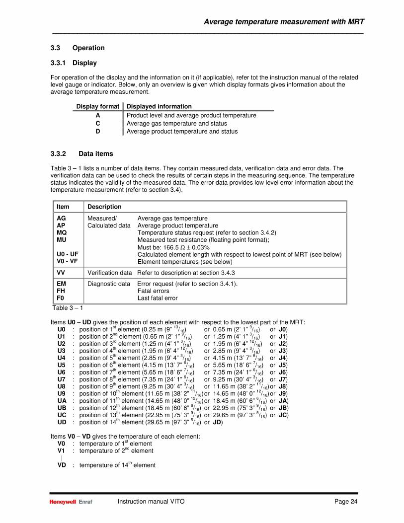
3.3.2 Data items Table 3 – 1 lists a number of data items. They contain measured data, verification data and error data. The verification data can be used to check the results of certain steps in the measuring sequence. The temperature status indicates the validity of the measured data. The error data provides low level error information about the temperature measurement (refer to section 3.4).
Item Description
AG AP MQ MU U0 - UF V0 - VF
Measured/ Average gas temperature Calculated data Average product temperature Temperature status request (refer to section 3.4.2) Measured test resistance (floating point format);
Must be: 166.5 Ω ± 0.03% Calculated element length with respect to lowest point of MRT (see below) Element temperatures (see below)
VV Verification data Refer to description at section 3.4.3
EM FH F0
Diagnostic data Error request (refer to section 3.4.1). Fatal errors Last fatal error
Table 3 – 1 Items U0 – UD gives the position of each element with respect to the lowest part of the MRT: U0 : position of 1
st element (0.25 m (9”
13/16) or 0.65 m (2’ 1”
9/16) or J0)
U1 : position of 2nd
element (0.65 m (2’ 1” 9/16) or 1.25 m (4’ 1”
3/16) or J1)
U2 : position of 3rd
element (1.25 m (4’ 1” 3/16) or 1.95 m (6’ 4”
12/16) or J2)
U3 : position of 4th element (1.95 m (6’ 4”
12/16) or 2.85 m (9’ 4”
3/16) or J3)
U4 : position of 5th element (2.85 m (9’ 4”
3/16) or 4.15 m (13’ 7”
6/16) or J4)
U5 : position of 6th element (4.15 m (13’ 7”
6/16) or 5.65 m (18’ 6”
7/16) or J5)
U6 : position of 7th element (5.65 m (18’ 6”
7/16) or 7.35 m (24’ 1”
6/16) or J6)
U7 : position of 8th element (7.35 m (24’ 1”
6/16) or 9.25 m (30’ 4”
3/16) or J7)
U8 : position of 9th element (9.25 m (30’ 4”
3/16) or 11.65 m (38’ 2”
11/16) or J8)
U9 : position of 10th element (11.65 m (38’ 2”
11/16) or 14.65 m (48’ 0”
12/16) or J9)
UA : position of 11th element (14.65 m (48’ 0”
12/16) or 18.45 m (60’ 6”
6/16) or JA)
UB : position of 12th element (18.45 m (60’ 6”
6/16) or 22.95 m (75’ 3”
9/16) or JB)
UC : position of 13th element (22.95 m (75’ 3”
9/16) or 29.65 m (97’ 3”
5/16) or JC)
UD : position of 14th element (29.65 m (97’ 3”
5/16) or JD)
Items V0 – VD gives the temperature of each element: V0 : temperature of 1
st element
V1 : temperature of 2nd
element | VD : temperature of 14
th element
Average temperature measurement with MRT ___________________________________________________________________________
Instruction manual VITO Page 25
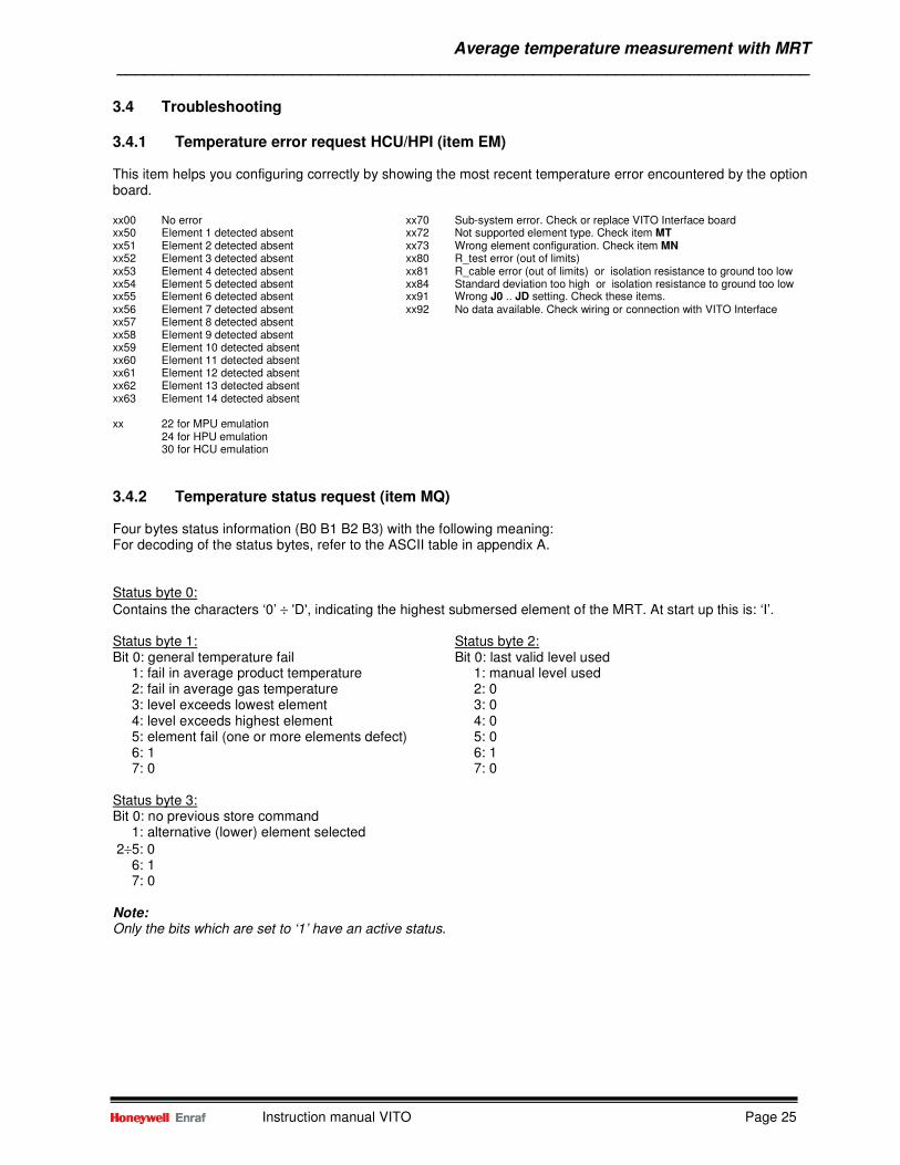
3.4 Troubleshooting 3.4.1 Temperature error request HCU/HPI (item EM) This item helps you configuring correctly by showing the most recent temperature error encountered by the option board. xx00 No error xx70 Sub-system error. Check or replace VITO Interface board xx50 Element 1 detected absent xx72 Not supported element type. Check item MT xx51 Element 2 detected absent xx73 Wrong element configuration. Check item MN xx52 Element 3 detected absent xx80 R_test error (out of limits) xx53 Element 4 detected absent xx81 R_cable error (out of limits) or isolation resistance to ground too low xx54 Element 5 detected absent xx84 Standard deviation too high or isolation resistance to ground too low xx55 Element 6 detected absent xx91 Wrong J0 .. JD setting. Check these items. xx56 Element 7 detected absent xx92 No data available. Check wiring or connection with VITO Interface xx57 Element 8 detected absent xx58 Element 9 detected absent xx59 Element 10 detected absent xx60 Element 11 detected absent xx61 Element 12 detected absent xx62 Element 13 detected absent xx63 Element 14 detected absent xx 22 for MPU emulation
24 for HPU emulation 30 for HCU emulation
3.4.2 Temperature status request (item MQ) Four bytes status information (B0 B1 B2 B3) with the following meaning: For decoding of the status bytes, refer to the ASCII table in appendix A. Status byte 0:
Contains the characters ‘0’ ÷ 'D', indicating the highest submersed element of the MRT. At start up this is: ‘I’. Status byte 1: Status byte 2: Bit 0: general temperature fail Bit 0: last valid level used 1: fail in average product temperature 1: manual level used 2: fail in average gas temperature 2: 0 3: level exceeds lowest element 3: 0 4: level exceeds highest element 4: 0 5: element fail (one or more elements defect) 5: 0 6: 1 6: 1 7: 0 7: 0 Status byte 3: Bit 0: no previous store command 1: alternative (lower) element selected
2÷5: 0 6: 1 7: 0 Note: Only the bits which are set to ‘1’ have an active status.
Average temperature measurement with MRT ___________________________________________________________________________
Instruction manual VITO Page 26
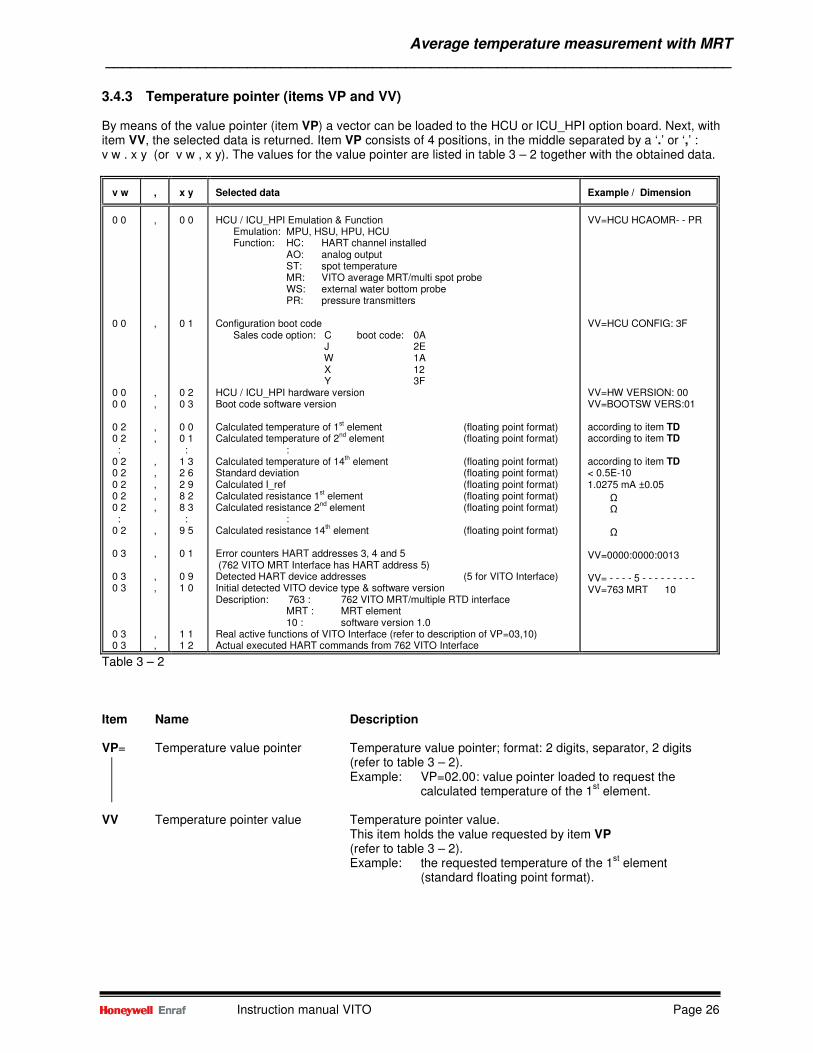
3.4.3 Temperature pointer (items VP and VV) By means of the value pointer (item VP) a vector can be loaded to the HCU or ICU_HPI option board. Next, with item VV, the selected data is returned. Item VP consists of 4 positions, in the middle separated by a ‘.’ or ‘,’ : v w . x y (or v w , x y). The values for the value pointer are listed in table 3 – 2 together with the obtained data.
v w
,
x y
Selected data
Example / Dimension
0 0 0 0 0 0 0 0 0 2 0 2 : 0 2 0 2 0 2 0 2 0 2 : 0 2 0 3 0 3 0 3 0 3 0 3
, , , , , , , , , , , , , , , , ,
0 0 0 1 0 2 0 3 0 0 0 1 : 1 3 2 6 2 9 8 2 8 3 : 9 5 0 1 0 9 1 0 1 1 1 2
HCU / ICU_HPI Emulation & Function
Emulation: MPU, HSU, HPU, HCU Function: HC: HART channel installed
AO: analog output ST: spot temperature MR: VITO average MRT/multi spot probe WS: external water bottom probe PR: pressure transmitters
Configuration boot code
Sales code option: C boot code: 0A J 2E W 1A X 12 Y 3F
HCU / ICU_HPI hardware version Boot code software version Calculated temperature of 1st element (floating point format) Calculated temperature of 2nd element (floating point format)
: Calculated temperature of 14th element (floating point format) Standard deviation (floating point format) Calculated I_ref (floating point format) Calculated resistance 1st element (floating point format) Calculated resistance 2nd element (floating point format)
: Calculated resistance 14th element (floating point format) Error counters HART addresses 3, 4 and 5 (762 VITO MRT Interface has HART address 5) Detected HART device addresses (5 for VITO Interface) Initial detected VITO device type & software version Description: 763 : 762 VITO MRT/multiple RTD interface
MRT : MRT element 10 : software version 1.0
Real active functions of VITO Interface (refer to description of VP=03,10) Actual executed HART commands from 762 VITO Interface
VV=HCU HCAOMR- - PR VV=HCU CONFIG: 3F VV=HW VERSION: 00 VV=BOOTSW VERS:01 according to item TD according to item TD according to item TD < 0.5E-10 1.0275 mA ±0.05 Ω Ω
Ω VV=0000:0000:0013 VV= - - - - 5 - - - - - - - - - VV=763 MRT 10
Table 3 – 2 Item Name Description VP= Temperature value pointer Temperature value pointer; format: 2 digits, separator, 2 digits (refer to table 3 – 2).
Example: VP=02.00: value pointer loaded to request the calculated temperature of the 1
st element.
VV Temperature pointer value Temperature pointer value.
This item holds the value requested by item VP (refer to table 3 – 2). Example: the requested temperature of the 1
st element
(standard floating point format).
Average temperature measurement with MPT / RTD ___________________________________________________________________________
Instruction manual VITO Page 27
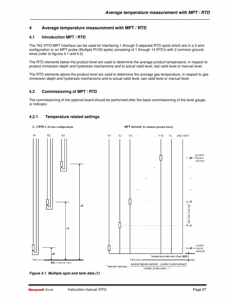
4 Average temperature measurement with MPT / RTD 4.1 Introduction MPT / RTD The 762 VITO MRT Interface can be used for interfacing 1 through 3 separate RTD spots which are in a 3 wire configuration or an MPT probe (Multiple Pt100 spots) consisting of 1 through 14 RTD's with 2 common ground wires (refer to figures 4.1 and 4.2). The RTD elements below the product level are used to determine the average product temperature, in respect to product immersion depth and hysteresis mechanisms and to actual valid level, last valid level or manual level. The RTD elements above the product level are used to determine the average gas temperature, in respect to gas immersion depth and hysteresis mechanisms and to actual valid level, last valid level or manual level.
4.2 Commissioning of MPT / RTD The commissioning of the optional board should be performed after the basic commissioning of the level gauge, or indicator.
4.2.1 Temperature related settings
Figure 4.1 Multiple spot and tank data (1)
Average temperature measurement with MPT / RTD ___________________________________________________________________________
Instruction manual VITO Page 28
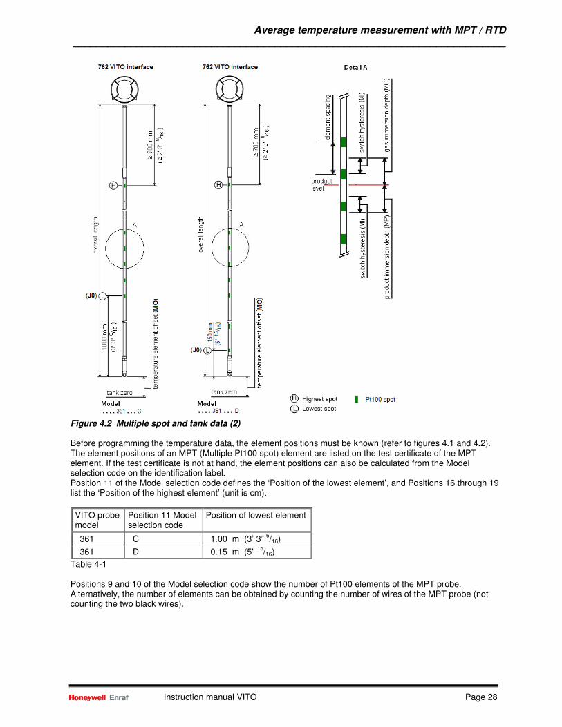
Figure 4.2 Multiple spot and tank data (2) Before programming the temperature data, the element positions must be known (refer to figures 4.1 and 4.2). The element positions of an MPT (Multiple Pt100 spot) element are listed on the test certificate of the MPT element. If the test certificate is not at hand, the element positions can also be calculated from the Model selection code on the identification label. Position 11 of the Model selection code defines the ‘Position of the lowest element’, and Positions 16 through 19 list the ‘Position of the highest element’ (unit is cm).
VITO probe model
Position 11 Model selection code
Position of lowest element
361 C 1.00 m (3’ 3” 6/16)
361 D 0.15 m (5” 15
/16)
Table 4-1 Positions 9 and 10 of the Model selection code show the number of Pt100 elements of the MPT probe. Alternatively, the number of elements can be obtained by counting the number of wires of the MPT probe (not counting the two black wires).
Average temperature measurement with MPT / RTD ___________________________________________________________________________
Instruction manual VITO Page 29
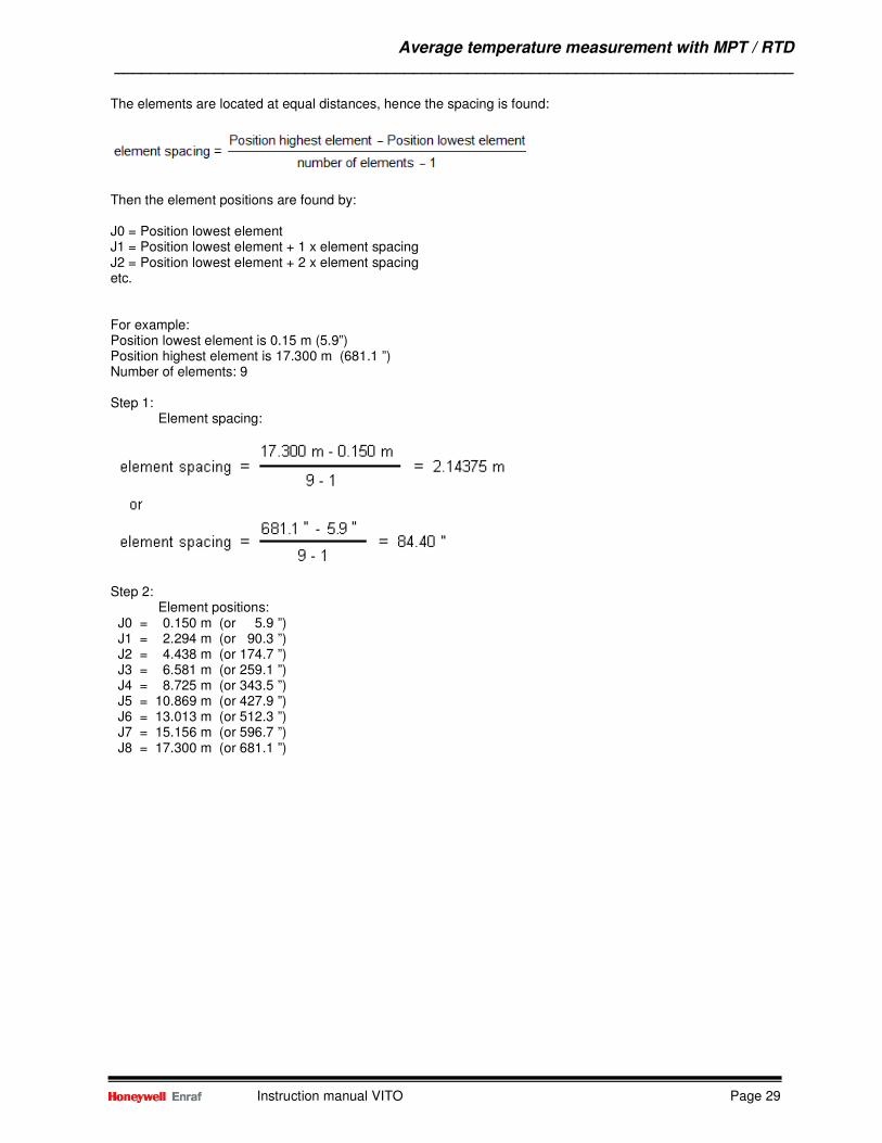
The elements are located at equal distances, hence the spacing is found:
Then the element positions are found by: J0 = Position lowest element J1 = Position lowest element + 1 x element spacing J2 = Position lowest element + 2 x element spacing etc. For example: Position lowest element is 0.15 m (5.9”) Position highest element is 17.300 m (681.1 ”) Number of elements: 9 Step 1: Element spacing:
Step 2: Element positions: J0 = 0.150 m (or 5.9 ”) J1 = 2.294 m (or 90.3 ”) J2 = 4.438 m (or 174.7 ”) J3 = 6.581 m (or 259.1 ”) J4 = 8.725 m (or 343.5 ”) J5 = 10.869 m (or 427.9 ”) J6 = 13.013 m (or 512.3 ”) J7 = 15.156 m (or 596.7 ”) J8 = 17.300 m (or 681.1 ”)
Average temperature measurement with MPT / RTD ___________________________________________________________________________
Instruction manual VITO Page 30
Refer to figures 4.1 and 4.2 Item Name Description W2= Protection level 2 Enter protection level 2 TD= Temperature dimension One character; either ‘C’ or ‘F’. Default set to C.
C : degrees Celsius F : degrees Fahrenheit
Both dimensions have the same format. MT= Element type Three ASCII characters. Selects the element type connected to
the 762 VITO MRT Interface. For 1 – 3 RTD’s and MPT probe, set this item to: ‘ SPL ’ (Pt100 large); range : -200 ÷ +250 °C (-328 ÷ +482 °F)
MN= Number of elements Two ASCII digits. This item specifies the number of elements
of the MPT probe. • 01 through 03 means RTD spot in a 3 wire connection • 04 through 14 means an MPT probe.
MO= Temperature element offset Format according to item LD. The offset represents the distance
from the tank zero level to the lowest position of the MPT probe. In case of the RTD spots this item should be left at 0.
Note: In case of ullage measurement, distance MO is taken from the upper reference point. J0 – JD= RTD element position. Format according to item LD. In case of the RTD spots items
J0 .. J2 represent the distance from tank zero level to the RTD spot. In case of a MPT probe items J0 .. JD represent the distance from the bottom of the probe (nearest to tank zero level) to the RTD elements. Refer to the description above to obtain the values for J0 .. JD. Note: Only enter as much element positions as specified by the number of elements, starting from J0 (see item MN).
MI= Switch hysteresis Format according to item LD. The distance MI is a hysteresis around the switching point of the temperature elements. MP= Product immersion depth Format according to item LD. The distance MP specifies the
minimum required liquid level above a spot before it is selected for the average product temperature calculation
MG= Gas immersion depth Format according to item LD. The distance MG specifies the minimum required distance below a spot before it is taken in the
average gas temperature calculation TU= Temperature status conversion One character (default: ‘T’)
This item is used to indicate the temperature status character in case of a reduced or not guaranteed temperature accuracy. This is the case when the temperature status is:
• out of specified temperature range • last valid level used • manual level used • level below lowest temperature element
If required, this item can be set to another character. EX Exit Exit protection level 2
Average temperature measurement with MPT / RTD ___________________________________________________________________________
Instruction manual VITO Page 31
4.2.2 Additional settings for and 877 FDI Item Name Description W2= Protection level 2 Enter protection level 2
OB= Option board *) Three ASCII characters. This item informs the XPU what option board is installed. That can be:
MPU : for HCU/ICU option board in MPU emulation mode HPU : for HCU/ICU option board in HPU emulation mode
EG= Enable temperature One ASCII character; either ‘D’ or ‘E’. With this item can be
transmission *) selected if the 877 FDI shall answer on a temperature request (C-record), addressed to the connected level gauge.
E : transmission of temperature record enabled D : transmission of temperature record disabled
Note: When item EG is set to ‘E’, make sure the related level gauge has no temperature option installed.
TF= Temperature source One ASCII character; either ‘I’ or ‘E’. this item selects if there is Selection a temperature measurement inside the indicator (internal) or to be fetched from the Enraf field bus (external).
E : Internal D : External
EX Exit Exit protection level 2 *) This item is not implemented in the XPU-2.
4.2.3 Temperature verification MPT (Multiple Pt100 spots) probes After the settings described in section 4.2.1 and, if applicable in section 4.2.2, are entered the temperature measurement is operational. The following checks can be made to verify if the settings are made correct and the product temperature reading is correct.
• Read item AP (Average Product temperature): This data item is preceded by four status characters. The first status character is a hexa-decimal number, indicating the highest selected element for average product temperature calculation. This can be judged, on basis of the product level, and with the items U0 – UF (calculated spot positions), item MO (temperature element offset), item MP (product immersion depth) and item MI (switch hysteresis).
Refer to figure 4.2: A spot element will be used in the average product temperature calculation if its position is below the actual level minus the product immersion depth. A spot element won’t be used in the average product temperature calculation if it is above the actual level minus the product immersion depth plus the switch hysteresis.
• Verify the average product temperature by manual measurement:
Refer to Appendix C for the procedure to verify the average product temperature reading by using a portable electronic thermometer.
Average temperature measurement with MPT / RTD ___________________________________________________________________________
Instruction manual VITO Page 32
4.3 Operation
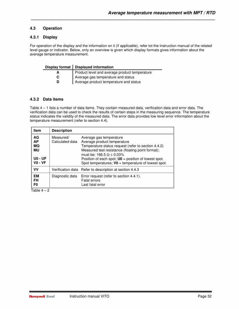
4.3.1 Display For operation of the display and the information on it (if applicable), refer tot the instruction manual of the related level gauge or indicator. Below, only an overview is given which display formats gives information about the average temperature measurement.
Display format Displayed information
A Product level and average product temperature
C Average gas temperature and status
D Average product temperature and status
4.3.2 Data items Table 4 – 1 lists a number of data items. They contain measured data, verification data and error data. The verification data can be used to check the results of certain steps in the measuring sequence. The temperature status indicates the validity of the measured data. The error data provides low level error information about the temperature measurement (refer to section 4.4).
Item Description
AG AP MQ MU U0 - UF V0 - VF
Measured/ Average gas temperature Calculated data Average product temperature Temperature status request (refer to section 4.4.2) Measured test resistance (floating point format); must be: 166.5 Ω ± 0.03% Position of each spot; U0 = position of lowest spot. Spot temperatures; V0 = temperature of lowest spot.
VV Verification data Refer to description at section 4.4.3
EM FH F0
Diagnostic data Error request (refer to section 4.4.1). Fatal errors Last fatal error
Table 4 – 2
Average temperature measurement with MPT / RTD ___________________________________________________________________________
Instruction manual VITO Page 33
4.4 Troubleshooting
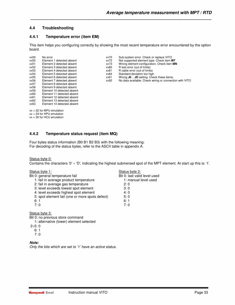
4.4.1 Temperature error (item EM) This item helps you configuring correctly by showing the most recent temperature error encountered by the option board. xx00 No error xx70 Sub-system error. Check or replace VITO xx50 Element 1 detected absent xx72 Not supported element type. Check item MT xx51 Element 2 detected absent xx73 Wrong element configuration. Check item MN xx52 Element 3 detected absent xx80 R test error (out of limits) xx53 Element 4 detected absent xx81 R cable error (out of limits) xx54 Element 5 detected absent xx84 Standard deviation too high xx55 Element 6 detected absent xx91 Wrong J0 .. JD setting. Check these items. xx56 Element 7 detected absent xx92 No data available. Check wiring or connection with VITO xx57 Element 8 detected absent xx58 Element 9 detected absent xx59 Element 10 detected absent xx60 Element 11 detected absent xx61 Element 12 detected absent xx62 Element 13 detected absent xx63 Element 14 detected absent xx = 22 for MPU emulation xx = 24 for HPU emulation xx = 30 for HCU emulation
4.4.2 Temperature status request (item MQ) Four bytes status information (B0 B1 B2 B3) with the following meaning: For decoding of the status bytes, refer to the ASCII table in appendix A. Status byte 0:
Contains the characters ‘0’ ÷ 'D', indicating the highest submersed spot of the MPT element. At start up this is: ‘I’. Status byte 1: Status byte 2: Bit 0: general temperature fail Bit 0: last valid level used 1: fail in average product temperature 1: manual level used 2: fail in average gas temperature 2: 0 3: level exceeds lowest spot element 3: 0 4: level exceeds highest spot element 4: 0 5: spot element fail (one or more spots defect) 5: 0 6: 1 6: 1 7: 0 7: 0 Status byte 3: Bit 0: no previous store command 1: alternative (lower) element selected
2÷5: 0 6: 1 7: 0 Note: Only the bits which are set to ‘1’ have an active status.
Average temperature measurement with MPT / RTD ___________________________________________________________________________
Instruction manual VITO Page 34
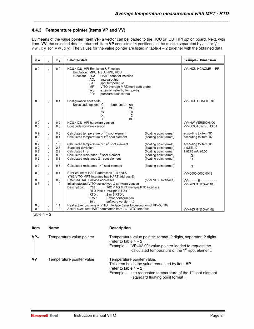
4.4.3 Temperature pointer (items VP and VV) By means of the value pointer (item VP) a vector can be loaded to the HCU or ICU_HPI option board. Next, with item VV, the selected data is returned. Item VP consists of 4 positions, in the middle separated by a ‘.’ or ‘,’ : v w . x y (or v w , x y). The values for the value pointer are listed in table 4 – 2 together with the obtained data.
v w
,
x y
Selected data
Example / Dimension
0 0 0 0 0 0 0 0 0 2 0 2 : 0 2 0 2 0 2 0 2 0 2 : 0 2 0 3 0 3 0 3 0 3 0 3
, , , , , , , , , , , , , , , , ,
0 0 0 1 0 2 0 3 0 0 0 1 : 1 3 2 6 2 9 8 2 8 3 : 9 5 0 1 0 9 1 0 1 1 1 2
HCU / ICU_HPI Emulation & Function
Emulation: MPU, HSU, HPU, HCU Function: HC: HART channel installed
AO: analog output ST: spot temperature MR: VITO average MRT/multi spot probe WS: external water bottom probe PR: pressure transmitters
Configuration boot code
Sales code option: C boot code: 0A J 2E W 1A X 12 Y 3F
HCU / ICU_HPI hardware version Boot code software version Calculated temperature of 1st spot element (floating point format) Calculated temperature of 2nd spot element (floating point format)
: Calculated temperature of 14th spot element (floating point format) Standard deviation (floating point format) Calculated I_ref (floating point format) Calculated resistance 1st spot element (floating point format) Calculated resistance 2nd spot element (floating point format)
: Calculated resistance 14th spot element (floating point format) Error counters HART addresses 3, 4 and 5 (762 VITO MRT Interface has HART address 5) Detected HART device addresses (5 for VITO Interface) Initial detected VITO device type & software version Description: 763 : 762 VITO MRT/multiple RTD interface
RTD PRB : Multiple RTD’s RTD : 2 or 3 RTD’s 3-W : 3-wire configuration 10 : software version 1.0
Real active functions of VITO Interface (refer to description of VP=03,10) Actual executed HART commands from 762 VITO Interface
VV=HCU HCAOMR- - PR VV=HCU CONFIG: 3F VV=HW VERSION: 00 VV=BOOTSW VERS:01 according to item TD according to item TD according to item TD < 0.5E-10 1.0275 mA ±0.05 Ω Ω
Ω VV=0000:0000:0013 VV= - - - - 5 - - - - - - - - - VV=763 RTD 3-W 10 VV=763 RTD 3-WIRE
Table 4 – 2 Item Name Description VP= Temperature value pointer Temperature value pointer; format: 2 digits, separator, 2 digits (refer to table 4 – 2).
Example: VP=02.00: value pointer loaded to request the calculated temperature of the 1
st spot element.
VV Temperature pointer value Temperature pointer value.
This item holds the value requested by item VP (refer to table 4 – 2). Example: the requested temperature of the 1
st spot element
(standard floating point format).
Water bottom measurement ___________________________________________________________________________
Instruction manual VITO Page 35
5 Water bottom measurement
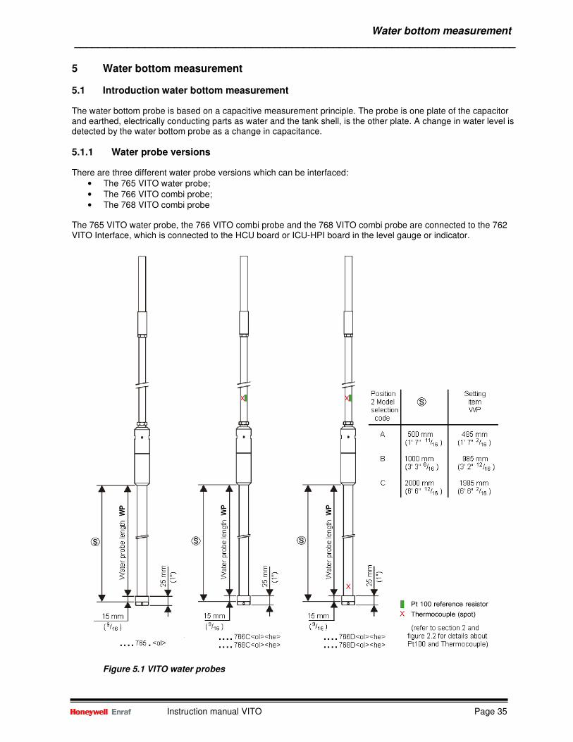
5.1 Introduction water bottom measurement The water bottom probe is based on a capacitive measurement principle. The probe is one plate of the capacitor and earthed, electrically conducting parts as water and the tank shell, is the other plate. A change in water level is detected by the water bottom probe as a change in capacitance.
5.1.1 Water probe versions There are three different water probe versions which can be interfaced:
• The 765 VITO water probe; • The 766 VITO combi probe; • The 768 VITO combi probe
The 765 VITO water probe, the 766 VITO combi probe and the 768 VITO combi probe are connected to the 762 VITO Interface, which is connected to the HCU board or ICU-HPI board in the level gauge or indicator.
Figure 5.1 VITO water probes
Water bottom measurement ___________________________________________________________________________
Instruction manual VITO Page 36
Refer to figure 5.1 • 765 VITO water probe. Can be delivered in three sensitive lengths for the water measurement: 0.5 m
(1’ 7” 11
/16), 1.0 m (3’ 3” 6/16) and 2.0 m (6’ 6”
12/16).
• 766 / 768 combi probe; lowest temperature element above water probe (position 8 of Model selection code is a ‘C’). There are three possible sensitive lengths for the water measurement: 0.5 m (1’ 7”
11/16),
1.0 m (3’ 3” 6/16) and 2.0 m (6’ 6”
12/16).
• 766 / 768 combi probe; lowest temperature element inside water probe (position 8 of Model selection code is a ‘D’). There are three possible sensitive lengths for the water measurement: 0.5 m (1’ 7”
11/16),
1.0 m (3’ 3” 6/16) and 2.0 m (6’ 6”
12/16).
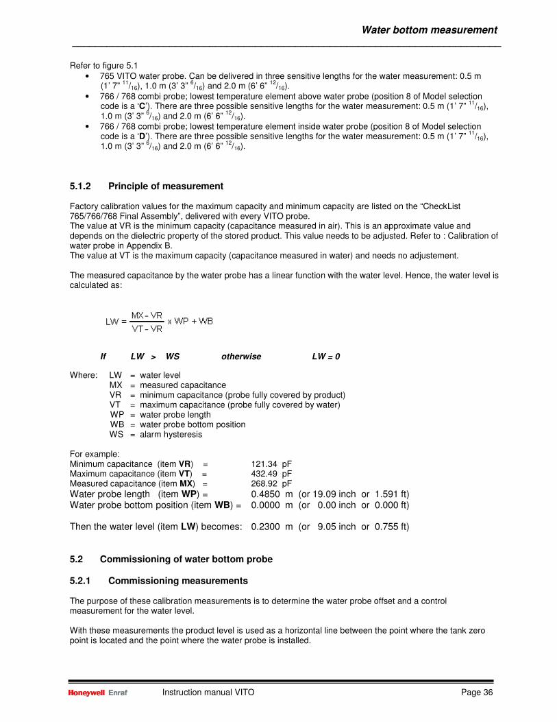
5.1.2 Principle of measurement Factory calibration values for the maximum capacity and minimum capacity are listed on the “CheckList 765/766/768 Final Assembly”, delivered with every VITO probe. The value at VR is the minimum capacity (capacitance measured in air). This is an approximate value and depends on the dielectric property of the stored product. This value needs to be adjusted. Refer to : Calibration of water probe in Appendix B. The value at VT is the maximum capacity (capacitance measured in water) and needs no adjustement. The measured capacitance by the water probe has a linear function with the water level. Hence, the water level is calculated as:
If LW > WS otherwise LW = 0
Where: LW = water level MX = measured capacitance VR = minimum capacitance (probe fully covered by product) VT = maximum capacitance (probe fully covered by water) WP = water probe length WB = water probe bottom position WS = alarm hysteresis For example: Minimum capacitance (item VR) = 121.34 pF Maximum capacitance (item VT) = 432.49 pF Measured capacitance (item MX) = 268.92 pF
Water probe length (item WP) = 0.4850 m (or 19.09 inch or 1.591 ft) Water probe bottom position (item WB) = 0.0000 m (or 0.00 inch or 0.000 ft) Then the water level (item LW) becomes: 0.2300 m (or 9.05 inch or 0.755 ft) 5.2 Commissioning of water bottom probe 5.2.1 Commissioning measurements The purpose of these calibration measurements is to determine the water probe offset and a control measurement for the water level. With these measurements the product level is used as a horizontal line between the point where the tank zero point is located and the point where the water probe is installed.
Water bottom measurement ___________________________________________________________________________
Instruction manual VITO Page 37
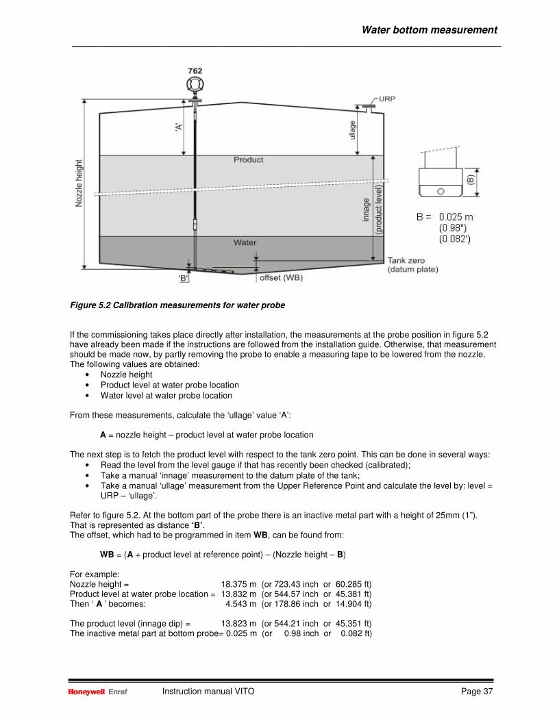
Figure 5.2 Calibration measurements for water probe If the commissioning takes place directly after installation, the measurements at the probe position in figure 5.2 have already been made if the instructions are followed from the installation guide. Otherwise, that measurement should be made now, by partly removing the probe to enable a measuring tape to be lowered from the nozzle. The following values are obtained:
• Nozzle height • Product level at water probe location • Water level at water probe location
From these measurements, calculate the ‘ullage’ value ‘A’: A = nozzle height – product level at water probe location The next step is to fetch the product level with respect to the tank zero point. This can be done in several ways:
• Read the level from the level gauge if that has recently been checked (calibrated); • Take a manual ‘innage’ measurement to the datum plate of the tank; • Take a manual ‘ullage’ measurement from the Upper Reference Point and calculate the level by: level =
URP – ‘ullage’. Refer to figure 5.2. At the bottom part of the probe there is an inactive metal part with a height of 25mm (1”). That is represented as distance ‘B’. The offset, which had to be programmed in item WB, can be found from: WB = (A + product level at reference point) – (Nozzle height – B) For example: Nozzle height = 18.375 m (or 723.43 inch or 60.285 ft) Product level at water probe location = 13.832 m (or 544.57 inch or 45.381 ft) Then ‘ A ’ becomes: 4.543 m (or 178.86 inch or 14.904 ft) The product level (innage dip) = 13.823 m (or 544.21 inch or 45.351 ft) The inactive metal part at bottom probe= 0.025 m (or 0.98 inch or 0.082 ft)
Water bottom measurement ___________________________________________________________________________
Instruction manual VITO Page 38
The offset (water probe bottom position) item WB then becomes: WB = (‘ A ’ + product level) - (nozzle height – ‘ B ’) = 0.016 m (or 0.62 inch or 0.052 ft) Note: If WB is a negative figure then it is possible to have a negative water level reading. Water probe length : The 765 VITO water probe and 766 / 768 VITO combi probe can have different water probe lengths. The actual water probe length can be found from the Model selection code of the probe. This length must be entered in item WP (water probe length). Table 5 – 1 gives an overview:
Position 2 Model selection code (765/766/768)
Item WP (LD=M) [metres]
Item WP (LD=F) [feet]
Item WP (LD=I) [inch]
Item WP (LD=P) [fractions]
A +000.4850 +0001.591 +00019.09 +01’07”02
B +000.9850 +0003.232 +00038.78 +03’02”12
C +001.9850 +0006.512 +00078.15 +06’06”02
Table 5 – 1 Minimum and Maximum capacitance : Factory calibration values for the maximum capacity and minimum capacity are listed on the “CheckList 765/766/768 Final Assembly”, delivered with every VITO probe. The value at VR is the minimum capacity (capacitance measured in air). This is an approximate value and depends on the dielectric property of the stored product. This value needs to be adjusted. The value at VT is the maximum capacity (capacitance measured in water) and needs no adjustement. Calibrating the water probe : Refer to Appendix B for information about calibrating the water probe. Where the water dip is mentioned, please refer to the measured water level at the probe position as described before.
Water bottom measurement ___________________________________________________________________________
Instruction manual VITO Page 39
5.2.2 Water probe settings Item Name Description W2= Protection level 2 Enter protection level 2
VR= Minimum water capacity Floating point format; default: +.00000000E+00. Enter the value obtained from the calculations in Appendix B. As an alternative, the value from VR as listed on the “CheckList 765/766/768 Final Assembly” can be used.
VT= Maximum water capacity Floating point format; default: +.00000000E+00. Enter the value
from VT as listed on the “CheckList 765/766/768 Final Assembly”. WB= Water probe bottom position Format according to item LD (default: + 000.0000 m) This item gives the offset to the water probe zero point in relation with the tank zero point. Refer to section 5.2.1 how to obtain this offset value. WP= Water probe length Format according to item LD (default: + 001.0000 m) The water probe length (together with the water probe
bottom position) is required to calculate the water level. Refer to section 5.2.1 which value needs to be entered.
WF= Water level field communication One character: ‘S’ or ‘D’. Only valid with 854 level gauges.
This item selects from which source the water level is measured and transmitted in the level record (B-record) to the system. S : from the water probe (VITO water sensor or side mounted water probe) D : from water dip (displacer) Select ‘S’ for 854 the gauges (default: D).
WH= Water high alarm Format according to item LD (default: +000.0000 m) With this item a water high alarm set point can be given. When active, the water high alarm condition is signalled on the instrument display in display format K (if display is available).
The water alarm information is also transmitted in the water level record (M-record).
WL= Water low alarm Format according to item LD (default: +000.0000 m) With this item a water low alarm set point can be given. When active, the water low alarm condition is signalled on the instrument display in display format K (if display is available).
The water alarm information is also transmitted in the water level record (M-record).
WS= Water alarm hysteresis Format according to item LD (default: + 000.0100 m). The water alarm hysteresis prevents the water alarm to be switched on and off when the water level is around the water high or water low alarm set point. EX Exit Exit protection level
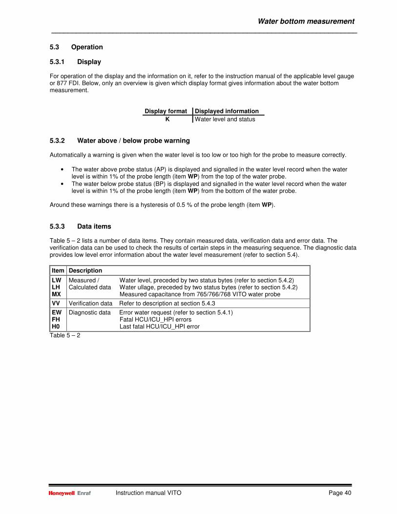
Water bottom measurement ___________________________________________________________________________
Instruction manual VITO Page 40
5.3 Operation
5.3.1 Display For operation of the display and the information on it, refer to the instruction manual of the applicable level gauge or 877 FDI. Below, only an overview is given which display format gives information about the water bottom measurement.
Display format Displayed information
K Water level and status
5.3.2 Water above / below probe warning Automatically a warning is given when the water level is too low or too high for the probe to measure correctly.
• The water above probe status (AP) is displayed and signalled in the water level record when the water level is within 1% of the probe length (item WP) from the top of the water probe.
• The water below probe status (BP) is displayed and signalled in the water level record when the water level is within 1% of the probe length (item WP) from the bottom of the water probe.
Around these warnings there is a hysteresis of 0.5 % of the probe length (item WP).
5.3.3 Data items Table 5 – 2 lists a number of data items. They contain measured data, verification data and error data. The verification data can be used to check the results of certain steps in the measuring sequence. The diagnostic data provides low level error information about the water level measurement (refer to section 5.4).
Item Description
LW LH MX
Measured / Water level, preceded by two status bytes (refer to section 5.4.2) Calculated data Water ullage, preceded by two status bytes (refer to section 5.4.2) Measured capacitance from 765/766/768 VITO water probe
VV Verification data Refer to description at section 5.4.3
EW FH H0
Diagnostic data Error water request (refer to section 5.4.1) Fatal HCU/ICU_HPI errors Last fatal HCU/ICU_HPI error
Table 5 – 2
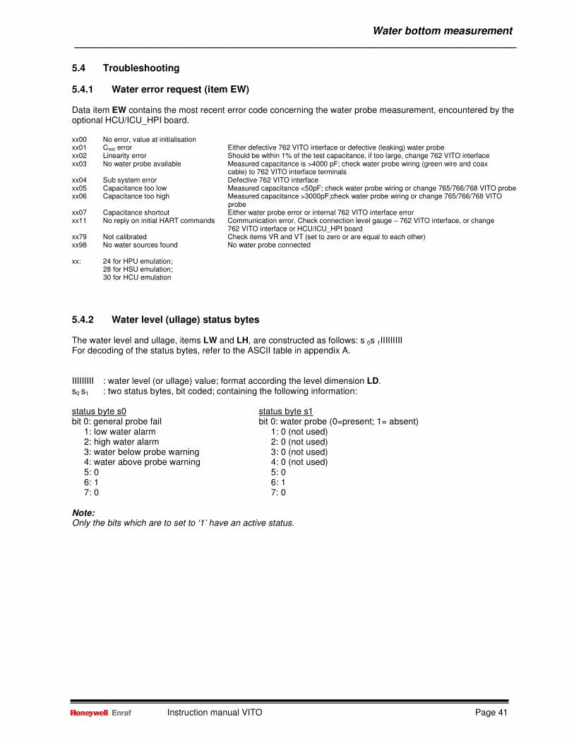
Water bottom measurement ___________________________________________________________________________
Instruction manual VITO Page 41
5.4 Troubleshooting
5.4.1 Water error request (item EW) Data item EW contains the most recent error code concerning the water probe measurement, encountered by the optional HCU/ICU_HPI board. xx00 No error, value at initialisation xx01 Ctest error Either defective 762 VITO interface or defective (leaking) water probe xx02 Linearity error Should be within 1% of the test capacitance, if too large, change 762 VITO interface xx03 No water probe available Measured capacitance is >4000 pF; check water probe wiring (green wire and coax cable) to 762 VITO interface terminals xx04 Sub system error Defective 762 VITO interface xx05 Capacitance too low Measured capacitance <50pF; check water probe wiring or change 765/766/768 VITO probe xx06 Capacitance too high Measured capacitance >3000pF;check water probe wiring or change 765/766/768 VITO
probe xx07 Capacitance shortcut Either water probe error or internal 762 VITO interface error xx11 No reply on initial HART commands Communication error. Check connection level gauge – 762 VITO interface, or change 762 VITO interface or HCU/ICU_HPI board xx79 Not calibrated Check items VR and VT (set to zero or are equal to each other) xx98 No water sources found No water probe connected xx: 24 for HPU emulation;
28 for HSU emulation; 30 for HCU emulation
5.4.2 Water level (ullage) status bytes The water level and ullage, items LW and LH, are constructed as follows: s 0s 1IIIIIIIII For decoding of the status bytes, refer to the ASCII table in appendix A. IIIIIIIII : water level (or ullage) value; format according the level dimension LD. s0 s1 : two status bytes, bit coded; containing the following information: status byte s0 status byte s1 bit 0: general probe fail bit 0: water probe (0=present; 1= absent) 1: low water alarm 1: 0 (not used) 2: high water alarm 2: 0 (not used) 3: water below probe warning 3: 0 (not used) 4: water above probe warning 4: 0 (not used) 5: 0 5: 0 6: 1 6: 1 7: 0 7: 0 Note: Only the bits which are to set to ‘1’ have an active status.
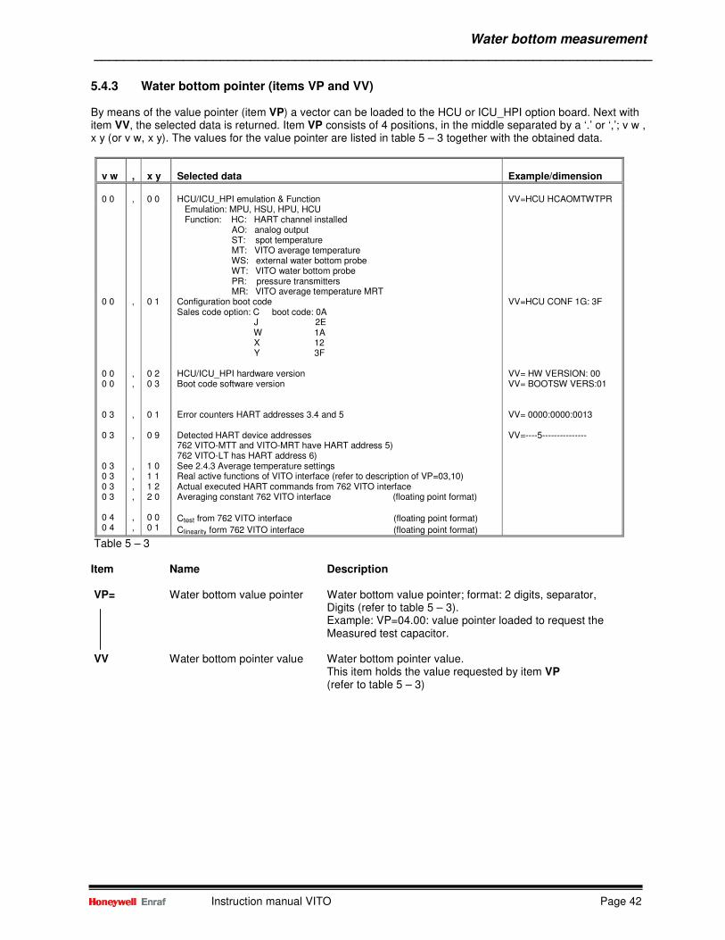
Water bottom measurement ___________________________________________________________________________
Instruction manual VITO Page 42
5.4.3 Water bottom pointer (items VP and VV) By means of the value pointer (item VP) a vector can be loaded to the HCU or ICU_HPI option board. Next with item VV, the selected data is returned. Item VP consists of 4 positions, in the middle separated by a ‘.’ or ‘,’; v w , x y (or v w, x y). The values for the value pointer are listed in table 5 – 3 together with the obtained data.
v w
,
x y
Selected data
Example/dimension
0 0
,
0 0
HCU/ICU_HPI emulation & Function
VV=HCU HCAOMTWTPR
Emulation: MPU, HSU, HPU, HCU Function: HC: HART channel installed AO: analog output ST: spot temperature MT: VITO average temperature WS: external water bottom probe WT: VITO water bottom probe PR: pressure transmitters MR: VITO average temperature MRT
0 0 0 0 0 0 0 3 0 3 0 3 0 3 0 3 0 3 0 4 0 4
, , , , , , , , , , ,
0 1 0 2 0 3 0 1 0 9 1 0 1 1 1 2 2 0 0 0 0 1
Configuration boot code Sales code option: C boot code: 0A J 2E W 1A X 12 Y 3F HCU/ICU_HPI hardware version Boot code software version Error counters HART addresses 3.4 and 5 Detected HART device addresses 762 VITO-MTT and VITO-MRT have HART address 5) 762 VITO-LT has HART address 6) See 2.4.3 Average temperature settings Real active functions of VITO interface (refer to description of VP=03,10) Actual executed HART commands from 762 VITO interface Averaging constant 762 VITO interface (floating point format)
Ctest from 762 VITO interface (floating point format)
Clinearity form 762 VITO interface (floating point format)
VV=HCU CONF 1G: 3F VV= HW VERSION: 00 VV= BOOTSW VERS:01 VV= 0000:0000:0013 VV=----5---------------
Table 5 – 3 Item Name Description VP= Water bottom value pointer Water bottom value pointer; format: 2 digits, separator, Digits (refer to table 5 – 3). Example: VP=04.00: value pointer loaded to request the Measured test capacitor. VV Water bottom pointer value Water bottom pointer value. This item holds the value requested by item VP (refer to table 5 – 3)
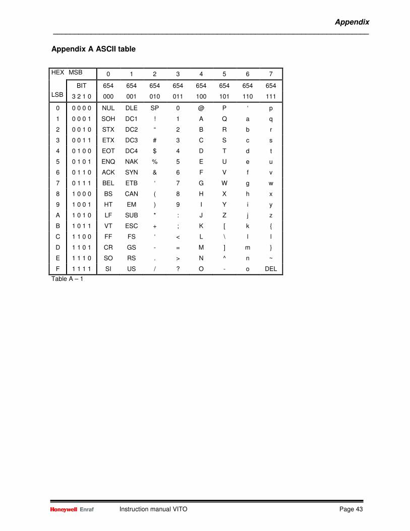
Appendix ___________________________________________________________________________
Instruction manual VITO Page 43
Appendix A ASCII table
HEX MSB 0 1 2 3 4 5 6 7
BIT 654 654 654 654 654 654 654 654
LSB 3 2 1 0 000 001 010 011 100 101 110 111
0 0 0 0 0 NUL DLE SP 0 @ P ‘ p
1 0 0 0 1 SOH DC1 ! 1 A Q a q
2 0 0 1 0 STX DC2 “ 2 B R b r
3 0 0 1 1 ETX DC3 # 3 C S c s
4 0 1 0 0 EOT DC4 $ 4 D T d t
5 0 1 0 1 ENQ NAK % 5 E U e u
6 0 1 1 0 ACK SYN & 6 F V f v
7 0 1 1 1 BEL ETB ‘ 7 G W g w
8 1 0 0 0 BS CAN ( 8 H X h x
9 1 0 0 1 HT EM ) 9 I Y i y
A 1 0 1 0 LF SUB * : J Z j z
B 1 0 1 1 VT ESC + ; K [ k
C 1 1 0 0 FF FS ‘ < L \ l l
D 1 1 0 1 CR GS - = M ] m
E 1 1 1 0 SO RS . > N ^ n ~
F 1 1 1 1 SI US / ? O - o DEL
Table A – 1
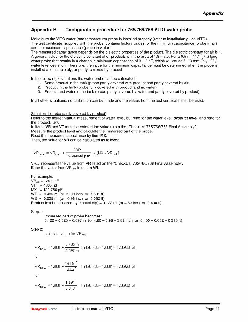
Appendix ___________________________________________________________________________
Instruction manual VITO Page 44
Appendix B Configuration procedure for 765/766/768 VITO water probe Make sure the VITO water (and temperature) probe is installed properly (refer to installation guide VITO). The test certificate, supplied with the probe, contains factory values for the minimum capacitance (probe in air) and the maximum capacitance (probe in water). The measured capacitance depends on the dielectric properties of the product. The dielectric constant for air is 1. A general value for the dielectric constant of oil products is in the area of 1.8 – 2.5. For a 0.5 m (1’ 7”
11/16) long
water probe that results in a change in minimum capacitance of 3 – 6 pF, which will cause 5 – 9 mm (3/16 –
6/16)
water level deviation. Therefore, the value for the minimum capacitance must be determined when the probe is installed and completely, or partly, covered by product. In the following 3 situations the water probe can be calibrated:
1. Some product in the tank (probe partly covered with product and partly covered by air) 2. Product in the tank (probe fully covered with product and no water) 3. Product and water in the tank (probe partly covered by water and partly covered by product)
In all other situations, no calibration can be made and the values from the test certificate shall be used. Situation 1 (probe partly covered by product) Refer to the figure: Manual measurement of water level, but read for the water level: product level and read for the product: air. In items VR and VT must be entered the values from the “CheckList 765/766/768 Final Assembly”. Measure the product level and calculate the immersed part of the probe. Read the measured capacitance by item MX. Then, the value for VR can be calculated as follows:
VRcal. represents the value from VR listed on the “CheckList 765/766/768 Final Assembly”. Enter the value from VRnew into item VR. For example: VRcal = 120.0 pF VT = 430.4 pF MX = 120.786 pF WP = 0.485 m (or 19.09 inch or 1.591 ft) WB = 0.025 m (or 0.98 inch or 0.082 ft) Product level (measured by manual dip) = 0.122 m (or 4.80 inch or 0.400 ft) Step 1:
Immersed part of probe becomes: 0.122 – 0.025 = 0.097 m (or 4.80 – 0.98 = 3.82 inch or 0.400 – 0.082 = 0.318 ft)
Step 2: calculate value for VRnew
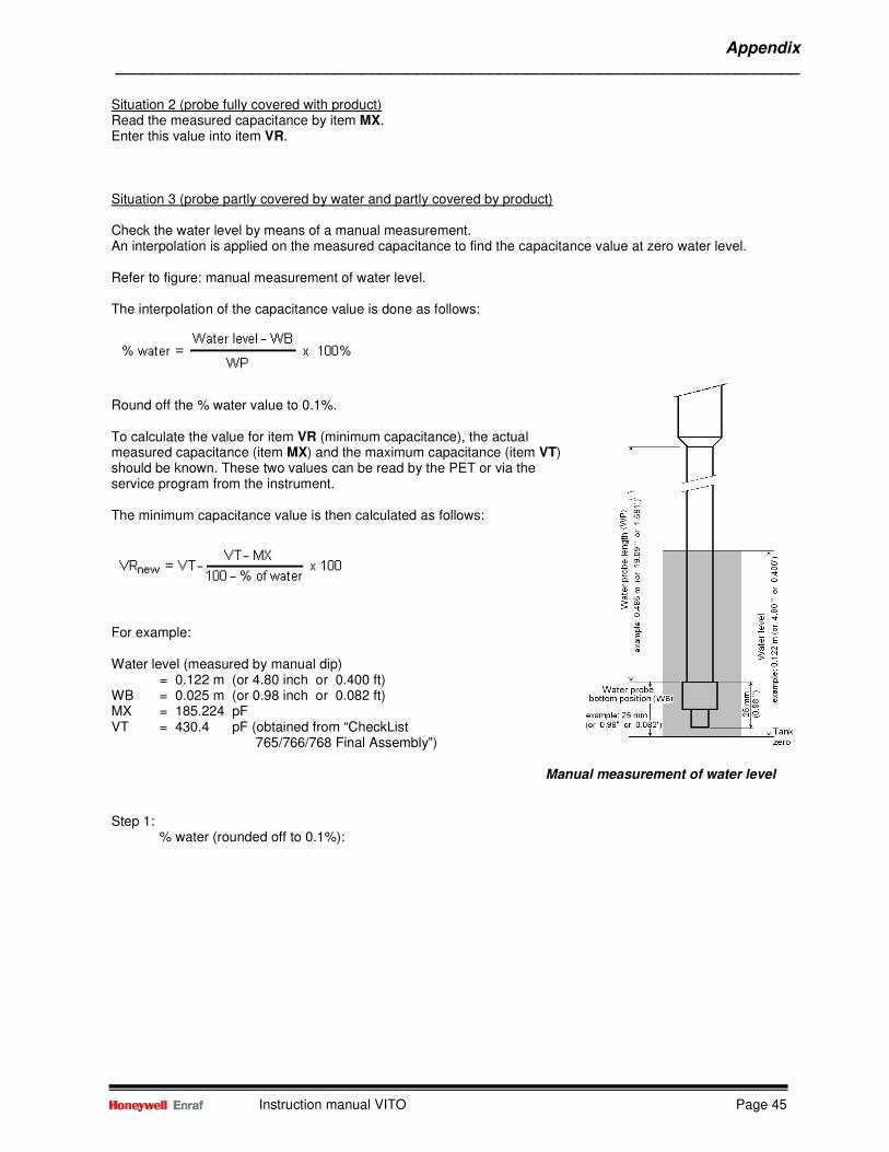
Appendix ___________________________________________________________________________
Instruction manual VITO Page 45
Situation 2 (probe fully covered with product) Read the measured capacitance by item MX. Enter this value into item VR. Situation 3 (probe partly covered by water and partly covered by product) Check the water level by means of a manual measurement. An interpolation is applied on the measured capacitance to find the capacitance value at zero water level. Refer to figure: manual measurement of water level. The interpolation of the capacitance value is done as follows:
Round off the % water value to 0.1%. To calculate the value for item VR (minimum capacitance), the actual measured capacitance (item MX) and the maximum capacitance (item VT) should be known. These two values can be read by the PET or via the service program from the instrument. The minimum capacitance value is then calculated as follows:
For example: Water level (measured by manual dip)
= 0.122 m (or 4.80 inch or 0.400 ft) WB = 0.025 m (or 0.98 inch or 0.082 ft) MX = 185.224 pF VT = 430.4 pF (obtained from “CheckList 765/766/768 Final Assembly”)
Manual measurement of water level Step 1:
% water (rounded off to 0.1%):
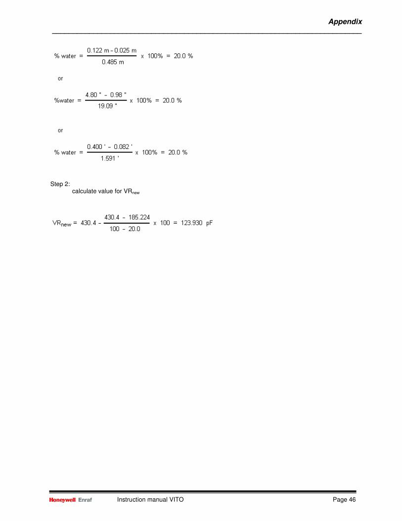
Appendix ___________________________________________________________________________
Instruction manual VITO Page 46
Step 2:
calculate value for VRnew
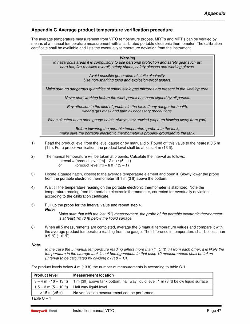
Appendix ___________________________________________________________________________
Instruction manual VITO Page 47
Appendix C Average product temperature verification procedure The average temperature measurement from VITO temperature probes, MRT’s and MPT’s can be verified by means of a manual temperature measurement with a calibrated portable electronic thermometer. The calibration certificate shall be available and lists the eventually temperature deviation from the instrument.
Warning In hazardous areas it is compulsory to use personal protection and safety gear such as:
hard hat, fire-resistive overall, safety shoes, safety glasses and working gloves.
Avoid possible generation of static electricity. Use non-sparking tools and explosion-proof testers.
Make sure no dangerous quantities of combustible gas mixtures are present in the working area.
Never start working before the work permit has been signed by all parties.
Pay attention to the kind of product in the tank. If any danger for health,
wear a gas mask and take all necessary precautions.
When situated at an open gauge hatch, always stay upwind (vapours blowing away from you).
Before lowering the portable temperature probe into the tank, make sure the portable electronic thermometer is properly grounded to the tank.
1) Read the product level from the level gauge or by manual dip. Round off this value to the nearest 0.5 m
(1 ft). For a proper verification, the product level shall be at least 4 m (13 ft). 2) The manual temperature will be taken at 5 points. Calculate the interval as follows:
Interval = (product level [m] – 2 m) / (5 – 1) or (product level [ft] – 6 ft) / (5 – 1)
3) Locate a gauge hatch, closest to the average temperature element and open it. Slowly lower the probe
from the portable electronic thermometer till 1 m (3 ft) above the bottom. 4) Wait till the temperature reading on the portable electronic thermometer is stabilized. Note the
temperature reading from the portable electronic thermometer, corrected for eventually deviations according to the calibration certificate.
5) Pull up the probe for the Interval value and repeat step 4. Note:
Make sure that with the last (5th) measurement, the probe of the portable electronic thermometer
is at least 1m (3 ft) below the liquid surface. 6) When all 5 measurements are completed, average the 5 manual temperature values and compare it with
the average product temperature reading from the gauge. The difference in temperature shall be less than 0.5 °C (1.0 °F).
Note:
In the case the 5 manual temperature reading differs more than 1 °C (2 °F) from each other, it is likely the temperature in the storage tank is not homogeneous. In that case 10 measurements shall be taken (Interval to be calculated by dividing by (10 – 1)).
For product levels below 4 m (13 ft) the number of measurements is according to table C-1:
Product level Measurement location
3 – 4 m (10 – 13 ft) 1 m (3ft) above tank bottom, half way liquid level, 1 m (3 ft) below liquid surface
1.5 – 3 m (5 – 10 ft) Half way liquid level
<1.5 m (<5 ft) No verification measurement can be performed.
Table C – 1
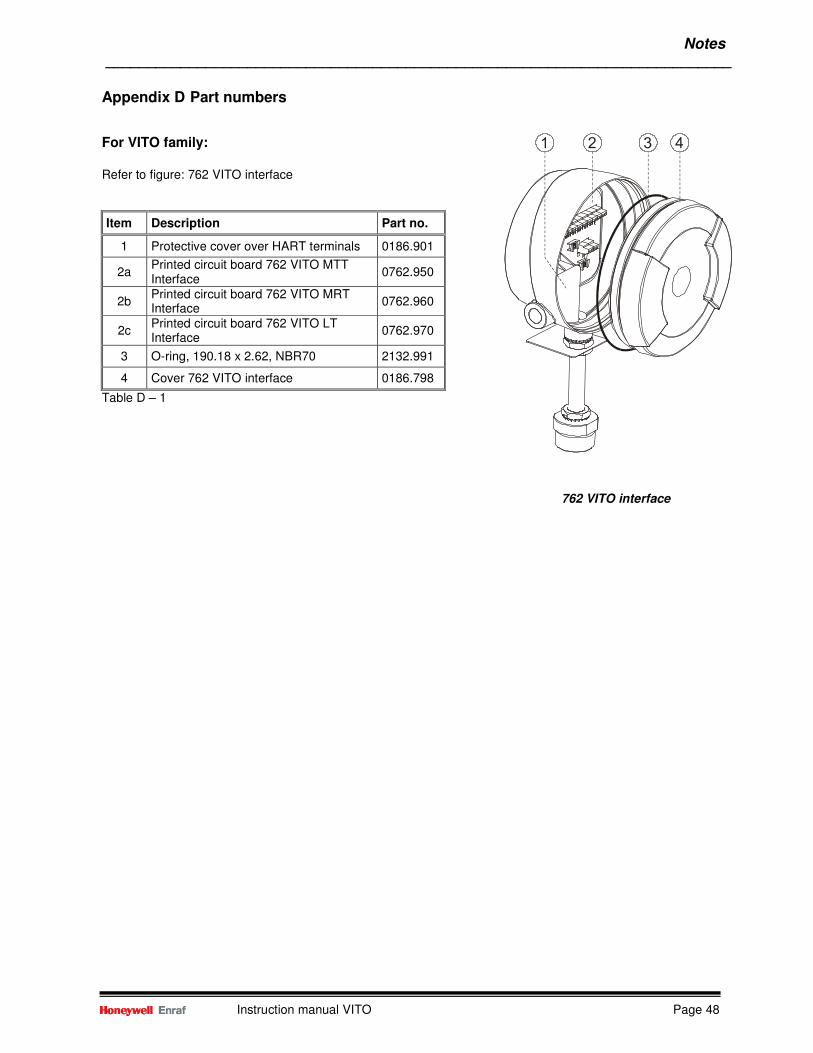
Notes ___________________________________________________________________________
Instruction manual VITO Page 48
Appendix D Part numbers
For VITO family:
Refer to figure: 762 VITO interface
Item Description Part no.
1 Protective cover over HART terminals 0186.901
2a Printed circuit board 762 VITO MTT Interface
0762.950
2b Printed circuit board 762 VITO MRT Interface
0762.960
2c Printed circuit board 762 VITO LT Interface
0762.970
3 O-ring, 190.18 x 2.62, NBR70 2132.991
4 Cover 762 VITO interface 0186.798
Table D – 1
762 VITO interface
Notes ___________________________________________________________________________
Instruction manual VITO Page 49
Appendix E Related documents Instruction manual series 854 ATG level gauge Instruction manual series 854 XTG level gauge Instruction manual 877 Field Display & Interface Instruction manual 97x SmartRadar series Installation guide 762 VITO Interfaces & VITO, MTT, LT, MRT and MPT probes Installation guide 864 MTT Multi Thermo sensor Thermometer

Honeywell Enraf
Delftechpark 39
2628 XJ Delft
The Netherlands
Tel: +31 (0)15-2701 100
Email: [email protected]
www.honeywellenraf.com
4416655 - Revision 6April 2013© 2013 Honeywell International Inc.