instruction manual - smc · safety instructions (read carefully before use.) thoroughly read this...
TRANSCRIPT

Doc. No.: EX**-OMC0012
Instruction Manual
SI Unit / DI Unit
EX240-SPR1
EX240-IE1
SMC CORPORATION

SAFETY INSTRUCTIONS
(Read carefully before use.)
Thoroughly read this technical instruction manual and related manuals mentioned here to
ensure the safety and proper operation of the product.
Level of potential hazard
! Warning: Operator error could result in serious injury or loss of life.
! Caution : Operator error could result in injury or equipment damage.
! Caution ① Thoroughly read this manual
Thoroughly read this manual and operate the product within the specified range following
every instruction.
② Handle with care
Do not drop the product and/or give excessive impact on the product.
③ Keep the specified voltage range
An operation error, breakage, electric shock and fire may occur if the product is operated
with voltage out of the specification.
④ Do not touch terminals and/or internal circuit board while they are energized
An operation error, breakage or electric shock may occur if you touch energized terminals
and/or internal circuit board.
⑤ Keep the ambient temperature specification
Use within the specified ambient temperature. Do not use the product in an atmosphere
subject to a sudden temperature change even if the temperature is within the specified
range.
⑥ Avoid foreign matter from getting inside the product
Make sure that foreign matter such as bits of wire does not enter the product. It may result
in a fire, failure or operation error.
! Warning
① The product is designed to use in ordinary full automation equipment. Prevent the use in
machinery and/or equipment where human life may be directly injured and malfunction or
failure may cause enormous loss.
② Do not disassemble the product for maintenance or modifications.
CONTENTS
1. Outline .............................. 1
2. Part numbers .............................. 1
3. System components .............................. 1
4. Appearance .............................. 2
5. Connector .............................. 3
5.1 Power supply connector .............................. 3
5.2 Communication connector .............................. 3
5.3 Input connector .............................. 4
6. Display .............................. 4
7. Wiring .............................. 5
7.1 Power supply wiring .............................. 5
7.2 Communication wiring .............................. 6
7.3 Input wiring .............................. 8
8. Solenoid valve .............................. 9
9. Setting ............................... 10
10. Specifications ............................... 11
11. Diagnosis ............................... 14
12. Configuration ............................... 16
13. I/O number allocation ............................... 18
14. Installation & Maintenance ............................... 19
15. GSD File / Type File ............................... 21
15.1 GSD File ............................... 21
15.1.1 EX240-SPR1 SW setting mode(SMC_1402.GSD) ......... 21
15.1.2 EX240-SPR1 HW setting mode(SMC_1403.GSD) ......... 22
15.2 Type File .............................. 23
1
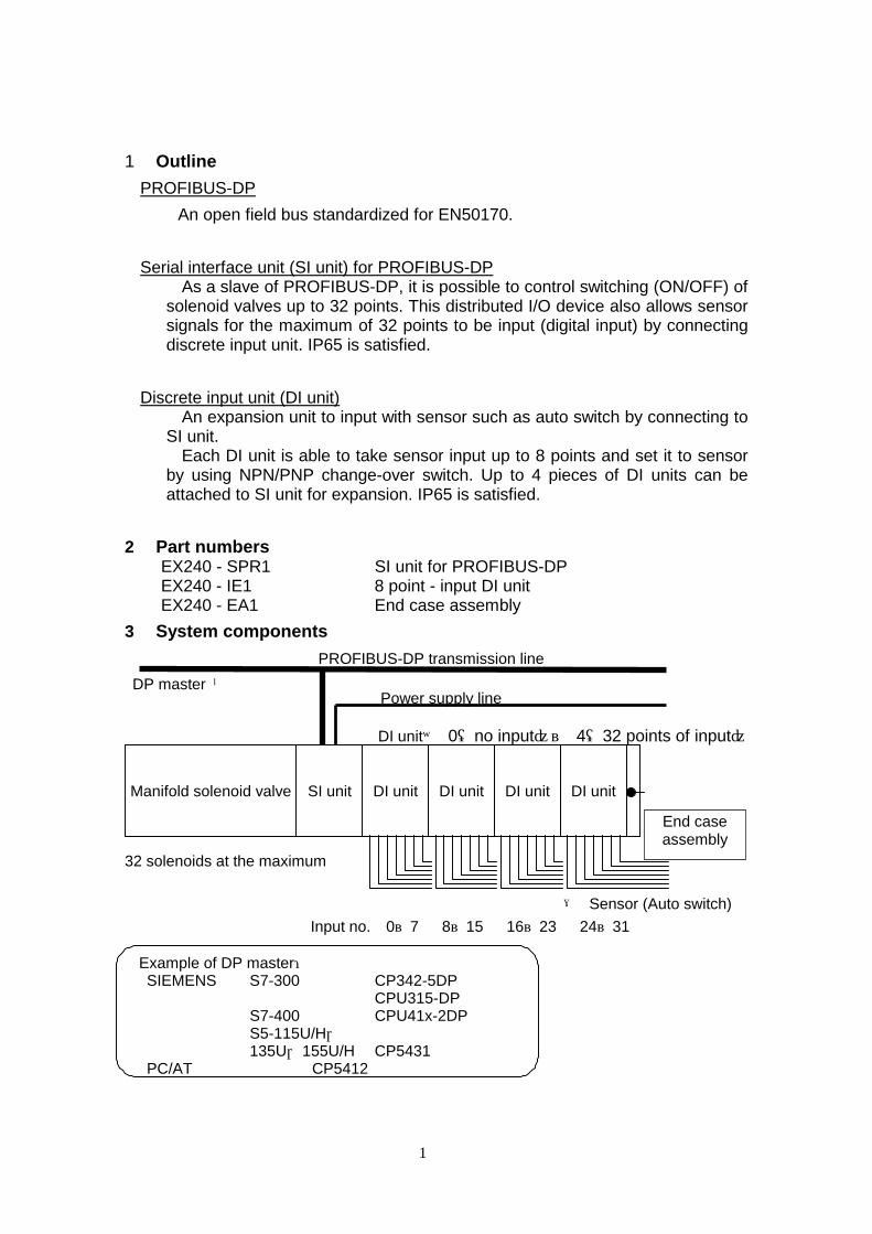
1 Outline
PROFIBUS-DP
An open field bus standardized for EN50170.
Serial interface unit (SI unit) for PROFIBUS-DP As a slave of PROFIBUS-DP, it is possible to control switching (ON/OFF) of
solenoid valves up to 32 points. This distributed I/O device also allows sensor signals for the maximum of 32 points to be input (digital input) by connecting discrete input unit. IP65 is satisfied.
Discrete input unit (DI unit) An expansion unit to input with sensor such as auto switch by connecting to
SI unit. Each DI unit is able to take sensor input up to 8 points and set it to sensor
by using NPN/PNP change-over switch. Up to 4 pieces of DI units can be attached to SI unit for expansion. IP65 is satisfied.
2 Part numbers EX240 - SPR1 SI unit for PROFIBUS-DP EX240 - IE1 8 point - input DI unit EX240 - EA1 End case assembly
3 System components
PROFIBUS-DP transmission line
DP master ←
DI unit× 0(no input)~ 4(32 points of input)
32 solenoids at the maximum
→ Sensor (Auto switch)
Input no. 0~7 8~15 16~23 24~31
Example of DP master: SIEMENS S7-300 CP342-5DP CPU315-DP S7-400 CPU41x-2DP S5-115U/H, 135U,155U/H CP5431 PC/AT CP5412
DI unit
DI unit
DI unit
DI unit Manifold solenoid valve
SI unit
Power supply line
End case assembly
2
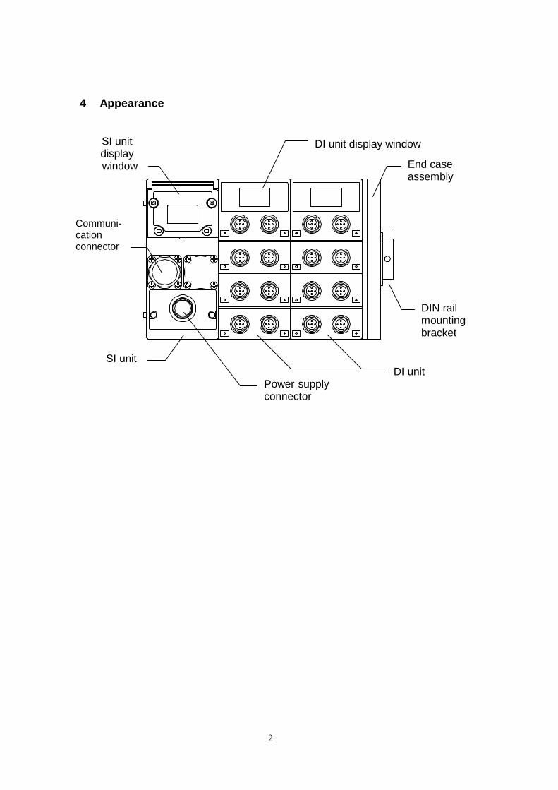
4 Appearance
SI unit DI unit
End case assembly
DIN rail mounting bracket
Power supply connector
Communi-cation connector
SI unit display
window
DI unit display window
3
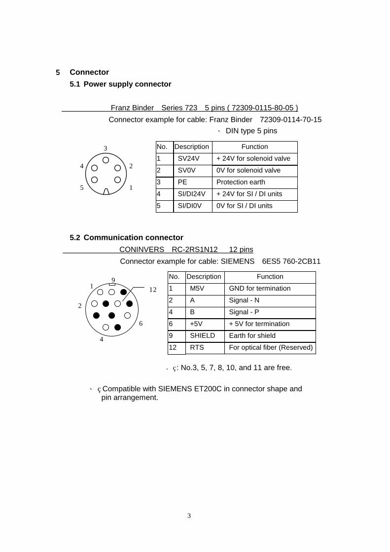
5555 Connector 5.1 Power supply connector
Franz Binder Series 723 5 pins ( 72309-0115-80-05 )
Connector example for cable: Franz Binder 72309-0114-70-15
※DIN type 5 pins
5.2 Communication connector
CONINVERS RC-2RS1N12 12 pins
Connector example for cable: SIEMENS 6ES5 760-2CB11
: No.3, 5, 7, 8, 10, and 11 are free.
※ Compatible with SIEMENS ET200C in connector shape and pin arrangement.
1
2
3
4
5
12 1
2
4
6
9 1 2 4 6 9 12
No. M5V A B +5V SHIELD RTS
Description
GND for termination Signal - N Signal - P + 5V for termination
Earth for shield For optical fiber (Reserved)
Function
1
2 3 4
5
No. SV24V
SV0V
PE
SI/DI24V SI/DI0V
Description + 24V for solenoid valve
0V for solenoid valve
Protection earth
+ 24V for SI / DI units
0V for SI / DI units
Function

4
5.3 Input connector
M12 5 pins(compatible with OMRON XS2F)× 8 pcs.
Connector example for cable: OMRON XS2G
※ No.2 pins of connectors with input no. 0, 2, 4, and 6 (connectors on the right side of each DI unit) are internally connected to no.4 pins of input no.1, 3, 5 and 7 (sensor input signals) one by one. This allows direct input for 2 points which are put in one cable with a collective connector.
※ For IP65 protection, Connect protection cap to all unused input connector,(Protection cap example: Hirschmann M12VS )
Connector: Input no. 0, 2, 4, 6 Input no. 1, 3, 5, 7 6 Display
SI unit
DI unit
Description SW+ N.C SW- SIGNAL PE
No. 1
2 3 4 5
Function Supply power + for sensor Free※ Supply power - for sensor Sensor input signal Protection earth for sensor
1
4
3
2
5
PWR(V) RUN
DIA BF DIA Lights up if any problem is detected by diagnosis.
Descp. Function
PWR(V) Lights up when power for solenoid valve is supplied. Lights off at lower than 19V of power
RUN Lights up during operation (while SI unit is energized).
BF Lights up if bus has any problem.
PWR
01
2
3
4
5
6
7
Descp.
PWR
0~7
Function
Lights up when power for sensor is supplied. Lights off when short-circuit suppressor works. Lights up when each sensor input turns on.
1 2 3 4
5
1 2
3 4
5
SW+
SIGNAL-n+1 SW-
SIGNAL-n PE
5
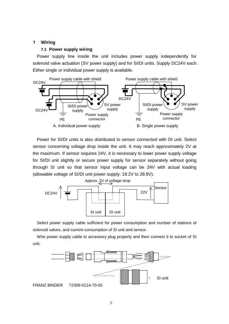
7777 Wiring 7.1 Power supply wiring
Power supply line inside the unit includes power supply independently for
solenoid valve actuation (SV power supply) and for SI/DI units. Supply DC24V each.
Either single or individual power supply is available. A. Individual power supply B. Single power supply
Power for SI/DI units is also distributed to sensor connected with DI unit. Select
sensor concerning voltage drop inside the unit. It may reach approximately 2V at
the maximum. If sensor requires 24V, it is necessary to lower power supply voltage
for SI/DI unit slightly or secure power supply for sensor separately without going
through SI unit so that sensor input voltage can be 24V with actual loading
(allowable voltage of SI/DI unit power supply: 19.2V to 28.8V). Select power supply cable sufficient for power consumption and number of stations of
solenoid valves, and current consumption of SI unit and sensor. Wire power supply cable to accessory plug properly and then connect it to socket of SI
unit. → SI unit FRANZ BINDER 72309-0114-70-05
SV power supply
PE Power supply
connector
DC24V
DC24V
Power supply cable with shield
SI/DI power supply
PE
DC24V
Power supply cable with shield
Approx. 2V of voltage drop
SI unit
DI unit
Sensor DC24V 22V
SI/DI power supply
Power supply connector
SV power supply
6
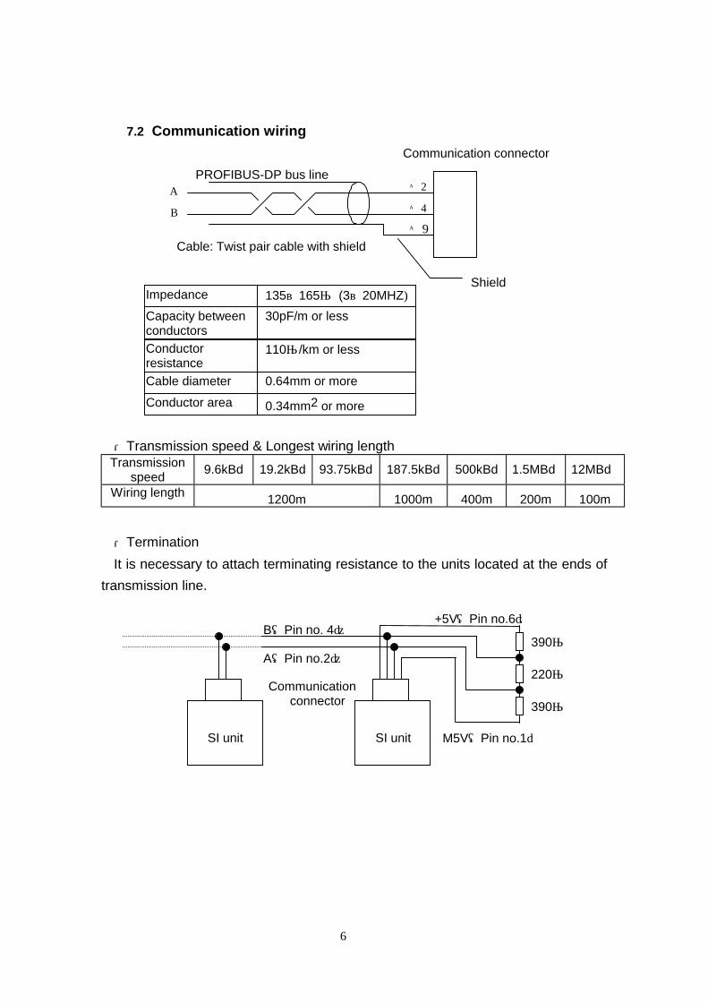
7.2 Communication wiring
Communication connector PROFIBUS-DP bus line Cable: Twist pair cable with shield
・Transmission speed & Longest wiring length
Transmission speed
9.6kBd 19.2kBd 93.75kBd 187.5kBd 500kBd 1.5MBd 12MBd
Wiring length 1200m 1000m 400m 200m 100m
・Termination
It is necessary to attach terminating resistance to the units located at the ends of
transmission line. Communication connector
2 4 9
A B
Shield Impedance 135~165Ω (3~20MHZ) Capacity between conductors
30pF/m or less
Conductor resistance
110Ω/km or less
Cable diameter 0.64mm or more Conductor area 0.34mm2 or more
SI unit
390Ω
220Ω
390Ω
+5V(Pin no.6)
M5V(Pin no.1)
B(Pin no. 4)
A(Pin no.2)
SI unit
7
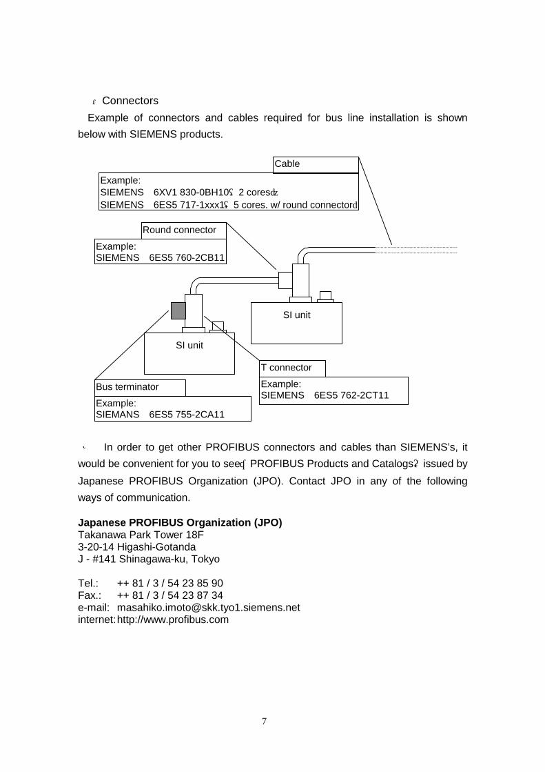
・Connectors Example of connectors and cables required for bus line installation is shown
below with SIEMENS products. ※ In order to get other PROFIBUS connectors and cables than SIEMENS’s, it
would be convenient for you to see“PROFIBUS Products and Catalogs”issued by
Japanese PROFIBUS Organization (JPO). Contact JPO in any of the following
ways of communication. Japanese PROFIBUS Organization (JPO) Takanawa Park Tower 18F 3-20-14 Higashi-Gotanda J - #141 Shinagawa-ku, Tokyo Tel.: ++ 81 / 3 / 54 23 85 90 Fax.: ++ 81 / 3 / 54 23 87 34 e-mail: [email protected] internet: http://www.profibus.com
SI unit
SI unit
T connector
Example: SIEMENS 6ES5 762-2CT11
Bus terminator Example: SIEMANS 6ES5 755-2CA11
Round connector
Example: SIEMENS 6ES5 760-2CB11
Cable
Example: SIEMENS 6XV1 830-0BH10(2 cores) SIEMENS 6ES5 717-1xxx1(5 cores, w/ round connector)
8
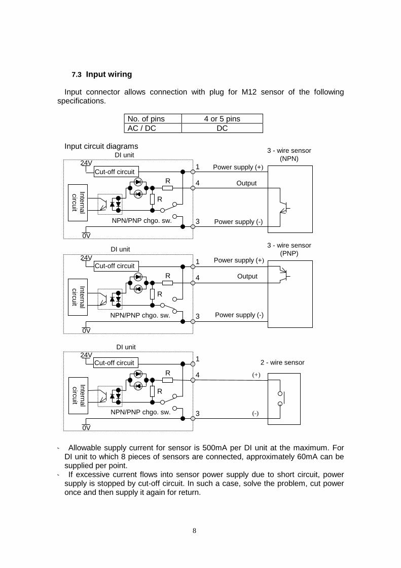
7.3 Input wiring Input connector allows connection with plug for M12 sensor of the following specifications.
No. of pins 4 or 5 pins AC / DC DC
Input circuit diagrams
※ Allowable supply current for sensor is 500mA per DI unit at the maximum. For
DI unit to which 8 pieces of sensors are connected, approximately 60mA can be supplied per point. ※ If excessive current flows into sensor power supply due to short circuit, power
supply is stopped by cut-off circuit. In such a case, solve the problem, cut power once and then supply it again for return.
R
R
DI unit 24V
0V
1
4
3
R
R
DI unit 24V
0V
(-)
(+) 2 - wire sensor 1
4
3
R
R
DI unit 24V
0V
Inte
rnal
circuit
NPN/PNP chgo. sw.
Power supply (+)
Power supply (-)
Output
3 - wire sensor (NPN)
1
4
3
Cut-off circuit
Cut-off circuit
Cut-off circuit
3 - wire sensor (PNP)
Power supply (+)
Power supply (-)
Output
NPN/PNP chgo. sw. In
tern
al
circuit
NPN/PNP chgo. sw.
Inte
rnal
circuit
9
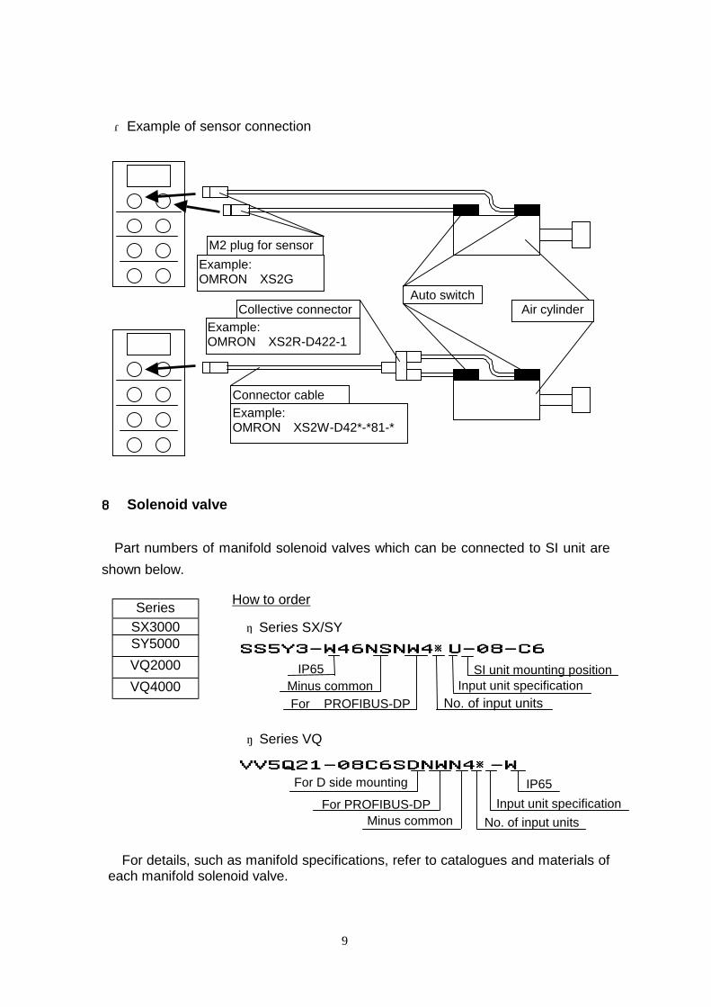
・Example of sensor connection
8888 Solenoid valve
Part numbers of manifold solenoid valves which can be connected to SI unit are
shown below.
Series
SX3000 SY5000
VQ2000
VQ4000
・ Series VQ
For details, such as manifold specifications, refer to catalogues and materials of each manifold solenoid valve.
Auto switch Air cylinder
M2 plug for sensor Example: OMRON XS2G
Collective connector Example: OMRON XS2R-D422-1
Connector cable Example: OMRON XS2W-D42*-*81-*
How to order
Input unit specification No. of input units
Minus common For PROFIBUS-DP
・ Series SX/SY
SS5Y3-W46NSNW4※U-08-C6SS5Y3-W46NSNW4※U-08-C6SS5Y3-W46NSNW4※U-08-C6SS5Y3-W46NSNW4※U-08-C6
IP65 SI unit mounting position
VV5Q21-08C6SDNWN4※-WVV5Q21-08C6SDNWN4※-WVV5Q21-08C6SDNWN4※-WVV5Q21-08C6SDNWN4※-W
For PROFIBUS-DP
No. of input units Input unit specification
IP65
Minus common
For D side mounting
10
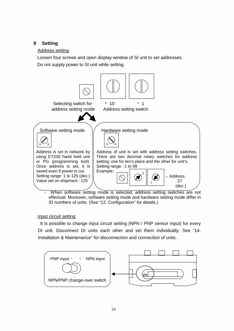
9 Setting
Address setting Loosen four screws and open display window of SI unit to set addresses.
Do not supply power to SI unit while setting.
Selecting switch for ×10 ×1 address setting mode Address setting switch Software setting mode Hardware setting mode
※ When software setting mode is selected, address setting switches are not
effectual. Moreover, software setting mode and hardware setting mode differ in ID numbers of units. (See “12. Configuration” for details.)
Input circuit setting
It is possible to change input circuit setting (NPN / PNP sensor input) for every
DI unit. Disconnect DI units each other and set them individually. See “14.
Installation & Maintenance” for disconnection and connection of units.
PNP input ← → NPN input NPN/PNP change-over switch
2
7
Address is set in network by using ET200 hand held unit or PG (programming tool). Once address is set, it is saved even if power is cut. Setting range: 1 to 125 (dec.) Value set on shipment : 125
Address of unit is set with address setting switches. There are two decimal rotary switches for address setting; one for ten’s place and the other for unit’s. Setting range : 1 to 99 Example: → Address 27 (dec.)
11
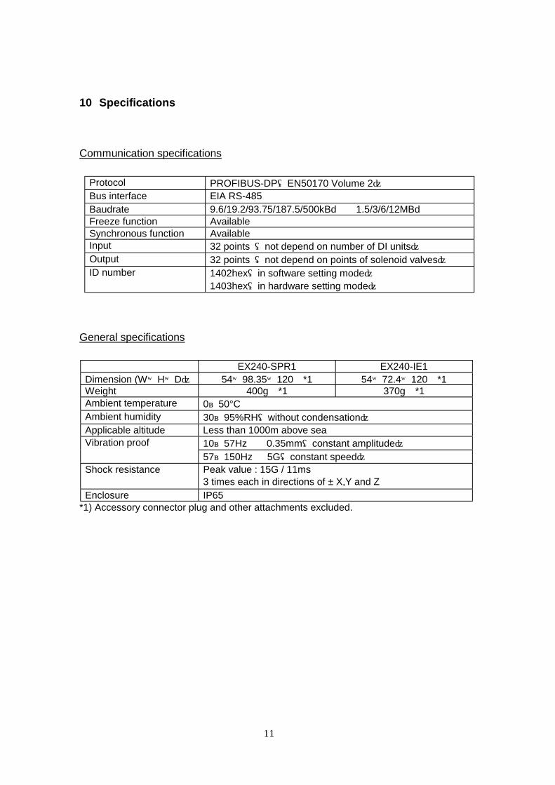
10 Specifications
Communication specifications
Protocol PROFIBUS-DP(EN50170 Volume 2) Bus interface EIA RS-485 Baudrate 9.6/19.2/93.75/187.5/500kBd 1.5/3/6/12MBd Freeze function Available Synchronous function Available Input 32 points (not depend on number of DI units) Output 32 points (not depend on points of solenoid valves) ID number 1402hex(in software setting mode)
1403hex(in hardware setting mode)
General specifications
EX240-SPR1 EX240-IE1 Dimension (W×H×D) 54×98.35×120 *1 54×72.4×120 *1 Weight 400g *1 370g *1 Ambient temperature 0~50°C Ambient humidity 30~95%RH(without condensation) Applicable altitude Less than 1000m above sea
10~57Hz 0.35mm(constant amplitude) Vibration proof
57~150Hz 5G(constant speed) Shock resistance Peak value : 15G / 11ms
3 times each in directions of ± X,Y and Z Enclosure IP65
*1) Accessory connector plug and other attachments excluded.
12
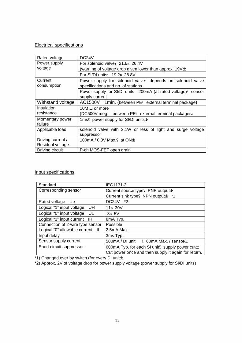
Electrical specifications
Rated voltage DC24V
For solenoid valve:21.6~26.4V (warning of voltage drop given lower than approx. 19V)
Power supply voltage
For SI/DI units:19.2~28.8V Power supply for solenoid valve:depends on solenoid valve specifications and no. of stations.
Current consumption
Power supply for SI/DI units:200mA (at rated voltage)+sensor supply current
Withstand voltage AC1500V 1min. (between PE-external terminal package) Insulation resistance
10M Ω or more (DC500V meg. between PE-external terminal package)
Momentary power failure
1ms(power supply for SI/DI units)
Applicable load solenoid valve with 2.1W or less of light and surge voltage suppressor
Driving current / Residual voltage
100mA / 0.3V Max.(at ON)
Driving circuit P-ch MOS-FET open drain
Input specifications
Standard IEC1131-2 Corresponding sensor Current source type(PNP output)
Current sink type(NPN output) *1 Rated voltage Ue DC24V *2 Logical “1” input voltage UH 11~30V Logical “0” input voltage UL -3~5V Logical “1” input current IH 8mA Typ. Connection of 2-wire type sensor Possible Logical “0” allowable current IL 2.5mA Max. Input delay 3ms Typ. Sensor supply current 500mA / DI unit (60mA Max. / sensor) Short circuit suppressor 600mA Typ. for each SI unit(supply power cut)
Cut power once and then supply it again for return. *1) Changed over by switch (for every DI unit) *2) Approx. 2V of voltage drop for power supply voltage (power supply for SI/DI units)
13
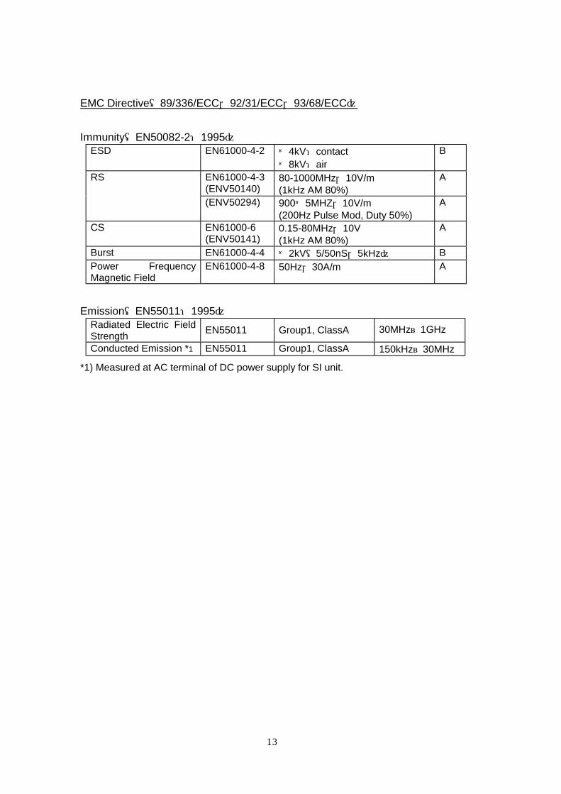
EMC Directive(89/336/ECC,92/31/ECC,93/68/ECC)
Immunity(EN50082-2:1995) ESD EN61000-4-2 ±4kV:contact
±8kV:air B
EN61000-4-3 (ENV50140)
80-1000MHz,10V/m (1kHz AM 80%)
A RS
(ENV50294) 900±5MHZ,10V/m (200Hz Pulse Mod, Duty 50%)
A
CS EN61000-6 (ENV50141)
0.15-80MHz,10V (1kHz AM 80%)
A
Burst EN61000-4-4 ±2kV(5/50nS,5kHz) B Power Frequency Magnetic Field
EN61000-4-8 50Hz,30A/m A
Emission(EN55011:1995) Radiated Electric Field Strength
EN55011 Group1, ClassA 30MHz~1GHz
Conducted Emission *1 EN55011 Group1, ClassA 150kHz~30MHz
*1) Measured at AC terminal of DC power supply for SI unit.
14
11 Diagnosis
PROFIBUS-DP has diagnosis function which allows to monitor condition of slave
between master - slaves. When it gets out of standard, SI unit sends diagnosis
information showing error to master and, at the same time, turns on DIA indication.
The following diagnosis functions are available.
Function Contents
Solenoid valve power supply voltage monitoring
Detects that solenoid valve voltage has decreased to approx. 19V or less.
DI unit condition monitoring Detects that sensor supply power has been turned off by short circuit cut-off.
Diagnosis information consists of 12 bytes. The first 6 bytes shows information
specified by PROFIBUS and the rest, 7 bytes , is peculiar to unit.
To see diagnosis information with master, refer to PROFIBUS specifications and
manual for master.
Example : SIEMENS S7-300,400 System function SFC13 “DPNORM_DG” is used. As error is detected by
diagnosis, OB82(diagnostic interrupt organization block)is automatically called out and error can be solved by programming error processing logic for OB82. CPU turns “STOP” if program is not loaded in OB82
Configurations of diagnosis information are as follows. (Normal values are shown.
“X” is variable.)
Byte0: Station status 1
Bit 7 0
Diag.Station_Not_Existent If SI unit is not recognized by
master : ” 1 ” *1
Diag.Station_Not_Ready If SI unit is not ready for data
transmission : ” 1 ”
Diag.Cfg_Fault If information on SI unit configuration sent from
master is incorrect : ” 1 ” *2
Diag.Ext_Diag Conditions of extended diagnosis regions(Byte6~12)are shown.
Diag.Not_Support If diagnosis is not supported : ” 1 ” *2
Diag.Invalid_Slave_Response if slave responds incorrectly: ” 1 ” *3
Diag.Prm_Fault If parameter for slave is incorrect : ” 1 ” *4
Diag.Master_Lock If SI unit is set for other master (Diag.Master_Add of Byte4 is different.): ” 1 ” *5
0 0 0 0 X 0 0 0
15
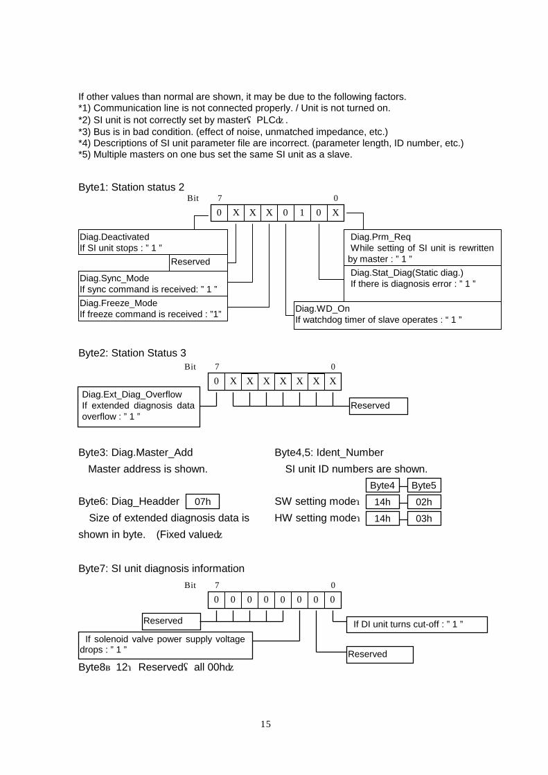
If other values than normal are shown, it may be due to the following factors. *1) Communication line is not connected properly. / Unit is not turned on. *2) SI unit is not correctly set by master(PLC). *3) Bus is in bad condition. (effect of noise, unmatched impedance, etc.) *4) Descriptions of SI unit parameter file are incorrect. (parameter length, ID number, etc.) *5) Multiple masters on one bus set the same SI unit as a slave.
Byte1: Station status 2
Byte2: Station Status 3
Byte3: Diag.Master_Add Byte4,5: Ident_Number
Master address is shown. SI unit ID numbers are shown.
Byte6: Diag_Headder SW setting mode:
Size of extended diagnosis data is HW setting mode:
shown in byte. (Fixed value)
Byte7: SI unit diagnosis information
Byte8~12:Reserved(all 00h)
Diag.Sync_Mode If sync command is received: ” 1 ”
Diag.Prm_Req While setting of SI unit is rewritten
by master : ” 1 ”
Diag.Stat_Diag(Static diag.) If there is diagnosis error : ” 1 ”
Diag.WD_On If watchdog timer of slave operates : “ 1 ”
Diag.Freeze_Mode If freeze command is received : ”1”
Reserved
Diag.Deactivated If SI unit stops : ” 1 ”
Bit 7 0 0 X X X 0 1 0 X
Bit 7 0 0 X X X X X X X
Reserved Diag.Ext_Diag_Overflow If extended diagnosis data overflow : ” 1 ”
14h 14h
02h 03h
Byte4 Byte5 07h
Bit 7 0 0 0 0 0 0 0 0 0
If solenoid valve power supply voltage drops : ” 1 ”
If DI unit turns cut-off : ” 1 ” Reserved
Reserved
16
12 Configuration
For PROFIBUS-DP, configuration information peculiar to each device (ID
number, data format, corresponding Baud rate, etc.) is supplied in the form of
device data base file (GSD File).
For SIEMENS master, system is configured by “Type File” which is equivalent to
GSD File.
Prepare GSD File or Type File for SI unit referring to “15. GSD File/ Type File”.
GSD File and Type File of SI unit differ depending on address setting mode
( which is changed over by address setting mode selecting switch).
GSD File: Smc_1402.gsd (in software setting mode) Smc_1403.gsd (in hardware setting mode) Type File: Sm1402ax.200 (in software setting mode) Sm1403ax.200 (in hardware setting mode)
How to set master for SI unit application is shown with SIEMENS STEP7 for
example.
① Copy SI unit Type File (Sm140?ax.200) below the directory:
˜ /Step7/S7data/Gsd/
( ˜ is a directory where STEP7 is installed.)
② Set up STEP7 and execute “Options”-”Update DDB” with HW Configuration
tool.
③ Open Hardware Catalog to find out additional “SI UNIT” icon under the
PROFIBUS DP - Additional FieldDevices. Drag and drop ”SMC EX240-SPR1
SW” (file for software setting mode) or “SMC EX240-SPR1 HW ” (file for
hardware setting mode) shown below the icon so as to add them to
PROFIBUS-DP line.
④ For the rest, follow the setting procedure for Distributed I/O device (address
parameter).
17
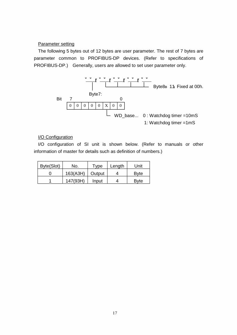
Parameter setting
The following 5 bytes out of 12 bytes are user parameter. The rest of 7 bytes are
parameter common to PROFIBUS-DP devices. (Refer to specifications of
PROFIBUS-DP.) Generally, users are allowed to set user parameter only.
00000000,,,,00000000,,,,00000000,,,,00000000,,,,00000000
Byte8~11:Fixed at 00h.
Byte7:
WD_base... 0 : Watchdog timer =10mS
1: Watchdog timer =1mS
I/O Configuration
I/O configuration of SI unit is shown below. (Refer to manuals or other
information of master for details such as definition of numbers.)
Byte(Slot) No. Type Length Unit
0 163(A3H) Output 4 Byte
1 147(93H) Input 4 Byte
Bit 7 0 0 0 0 0 0 X 0 0
18
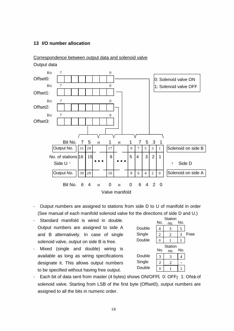
13 I/O number allocation
Correspondence between output data and solenoid valve
Output data
Offset0:
Offset1:
Offset2:
Offset3:
Bit No. 7 5 … 1 … 1 7 5 3 1
No. of stations 16 15 9 5 4 3 2 1
Side U ← → Side D
Bit No. 6 4 … 0 … 0 6 4 2 0
Valve manifold
※ Output numbers are assigned to stations from side D to U of manifold in order
(See manual of each manifold solenoid valve for the directions of side D and U.)
※ Standard manifold is wired in double.
Output numbers are assigned to side A
and B alternatively. In case of single
solenoid valve, output on side B is free.
※ Mixed (single and double) wiring is
available as long as wiring specifications
designate it. This allows output numbers
to be specified without having free output.
※ Each bit of data sent from master (4 bytes) shows ON/OFF(0: OFF,1: ON)of
solenoid valve. Starting from LSB of the first byte (Offset0), output numbers are
assigned to all the bits in numeric order.
Bit 7 0
Bit 7 0
Bit 7 0
Bit 7 0
9
8
17
16
29
28
31
30
1
0
3
2
5
4
7
6
Solenoid on side B Output No.
0: Solenoid valve ON
1: Solenoid valve OFF
1 2 3
0
5
1 2 3 4
Free
Station no. No. No.
Double
Single Double
1 2 3
0
4
1 2 - 3
Output No. Solenoid on side A
Station no. No. No.
Double
Single Double
19
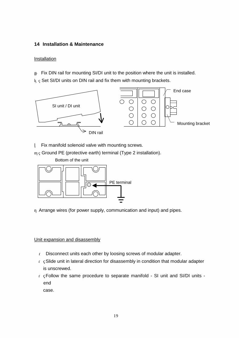
14 Installation & Maintenance
Installation
① Fix DIN rail for mounting SI/DI unit to the position where the unit is installed.
② Set SI/DI units on DIN rail and fix them with mounting brackets.
③ Fix manifold solenoid valve with mounting screws.
④ Ground PE (protective earth) terminal (Type 2 installation).
⑤Arrange wires (for power supply, communication and input) and pipes.
Unit expansion and disassembly
・ Disconnect units each other by loosing screws of modular adapter.
・ Slide unit in lateral direction for disassembly in condition that modular adapter
is unscrewed.
・ Follow the same procedure to separate manifold - SI unit and SI/DI units -
end
case.
DIN rail
SI unit / DI unit
End case
Mounting bracket
PE terminal
Bottom of the unit

20
・ For connection by the unit, follow the procedure backwards. Make sure that
joint is properly set. If not, liquid and particles may enter the inside of unit.
Check the following points to confirm proper joint setting.
① No missing joint.
② No breakage, falling and twist in joint packing.
③ No foreign matter adhered.
④ No inclined mounting.
・ Keep tightening torque specification for modular adapter. If tightening torque
is
insufficient or modular adapter is inclined, liquid and particles may enter the
inside of unit.
・ To add DI units, remove end plate following the procedure above. Put it back
when additional DI units are attached.
Modular adapter
Joint
Square nut
Tightening torque:
14Kgf・cm
Sliding direction
SI
unit
ユニッ
DI
unit
1
DI
unit
2
DI
unit
3
En
d ca
se
SI
unit
DI
unit
1
DI
unit
2
ユニッ
DI
unit
3
En
d ca
se
DI
unit
4

21
22
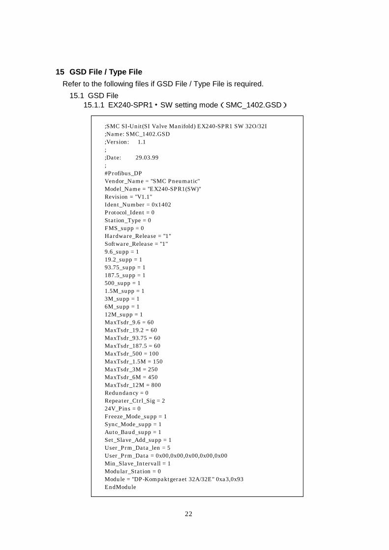
15 GSD File / Type File
Refer to the following files if GSD File / Type File is required.
15.1 GSD File 15.1.1 EX240-SPR1・SW setting mode(SMC_1402.GSD)
;SMC SI-Unit(SI Valve Manifold) EX240-SPR1 SW 32O/32I ;Name: SMC_1402.GSD ;Version: 1.1 ; ;Date: 29.03.99 ; #Profibus_DP Vendor_Name = "SMC Pneumatic" Model_Name = "EX240-SPR1(SW)" Revision = "V1.1" Ident_Number = 0x1402 Protocol_Ident = 0 Station_Type = 0 FMS_supp = 0 Hardware_Release = "1" Software_Release = "1" 9.6_supp = 1 19.2_supp = 1 93.75_supp = 1 187.5_supp = 1 500_supp = 1 1.5M_supp = 1 3M_supp = 1 6M_supp = 1 12M_supp = 1 MaxTsdr_9.6 = 60 MaxTsdr_19.2 = 60 MaxTsdr_93.75 = 60 MaxTsdr_187.5 = 60 MaxTsdr_500 = 100 MaxTsdr_1.5M = 150 MaxTsdr_3M = 250 MaxTsdr_6M = 450 MaxTsdr_12M = 800 Redundancy = 0 Repeater_Ctrl_Sig = 2 24V_Pins = 0 Freeze_Mode_supp = 1 Sync_Mode_supp = 1 Auto_Baud_supp = 1 Set_Slave_Add_supp = 1 User_Prm_Data_len = 5 User_Prm_Data = 0x00,0x00,0x00,0x00,0x00 Min_Slave_Intervall = 1 Modular_Station = 0 Module = "DP-Kompaktgeraet 32A/32E" 0xa3,0x93 EndModule

23
15.1.2 EX240-SPR1・HW setting mode(SMC_1403.GSD) ;SMC SI-Unit(SI Valve Manifold) EX240-SPR1 HW 32O/32I ;Name: SMC_1403.GSD ;Version: 1.1 ; ;Date: 29.03.99 ; #Profibus_DP Vendor_Name = "SMC Pneumatic" Model_Name = "EX240-SPR1(HW)" Revision = "V1.1" Ident_Number = 0x1403 Protocol_Ident = 0 Station_Type = 0 FMS_supp = 0 Hardware_Release = "1" Software_Release = "1" 9.6_supp = 1 19.2_supp = 1 93.75_supp = 1 187.5_supp = 1 500_supp = 1 1.5M_supp = 1 3M_supp = 1 6M_supp = 1 12M_supp = 1 MaxTsdr_9.6 = 60 MaxTsdr_19.2 = 60 MaxTsdr_93.75 = 60 MaxTsdr_187.5 = 60 MaxTsdr_500 = 100 MaxTsdr_1.5M = 150 MaxTsdr_3M = 250 MaxTsdr_6M = 450 MaxTsdr_12M = 800 Redundancy = 0 Repeater_Ctrl_Sig = 2 24V_Pins = 0 Freeze_Mode_supp = 1 Sync_Mode_supp = 1 Auto_Baud_supp = 1 Set_Slave_Add_supp = 0 User_Prm_Data_len = 5 User_Prm_Data = 0x00,0x00,0x00,0x00,0x00 Min_Slave_Intervall = 1 Modular_Station = 0 Module = "DP-Kompaktgeraet 32A/32E" 0xa3,0x93 EndModule
24
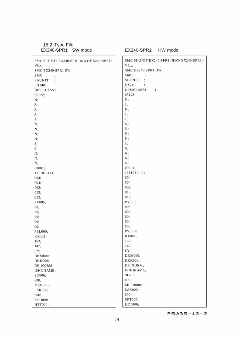
15.2 Type File EX240-SPR1 SW mode SMC SI-UNIT EX240-SPR1 (SW)<EX240-SPR1> V5.x; SMC EX240-SPR1 SW; SMC ; SI-UNIT ; EX240 ; DPS/CLASS1 ; 05122; N; J; J; J; J; N; N; N; N; J; 0; N; N; N; 00001; 1111011111; 004; 004; 002; 013; 012; PV005; 00; 00; 00; 00; 00; PSL000; KX002; 163; 147; SY; DKM000; DKK000; DP_NORM; ISNONAME; SO000; 008; MLFB000; LSK000; 000; SPT000; HTT000;
EX240-SPR1 HW mode SMC SI-UNIT EX240-SPR1 (HW)<EX240-SPR1> V5.x; SMC EX240-SPR1 HW; SMC ; SI-UNIT ; EX240 ; DPS/CLASS1 ; 05123; N; J; N; J; J; N; N; N; N; J; 0; N; N; N; 00001; 1111011111; 004; 004; 002; 013; 012; PV005; 00; 00; 00; 00; 00; PSL000; KX002; 163; 147; SY; DKM000; DKK000; DP_NORM; ISNONAME; SO000; 008; MLFB000; LSK000; 000; SPT000; HTT000;
P5035-12-2