instruction manual model: jh & jva - jovenelectric.com · • instruction manual model: jh...
TRANSCRIPT
• INSTRUCTION MANUAL MODEL: JH & JVA
CONNECTION OF OVERFLOW PIPE3.3
1. Open control valve in cold water supply line and all hot water faucets to allow trapped air to be vented out from the heater tank and piping.
2. Allow the heater tank to completely fill with water as indicated by a steady flow of water from the hot water faucets without switching on the electrical supply.
3. Turn off all hot water faucets. Check all pipe connections to ensure that they are properly sealed against leakage.
TO FILL HEATER TANK
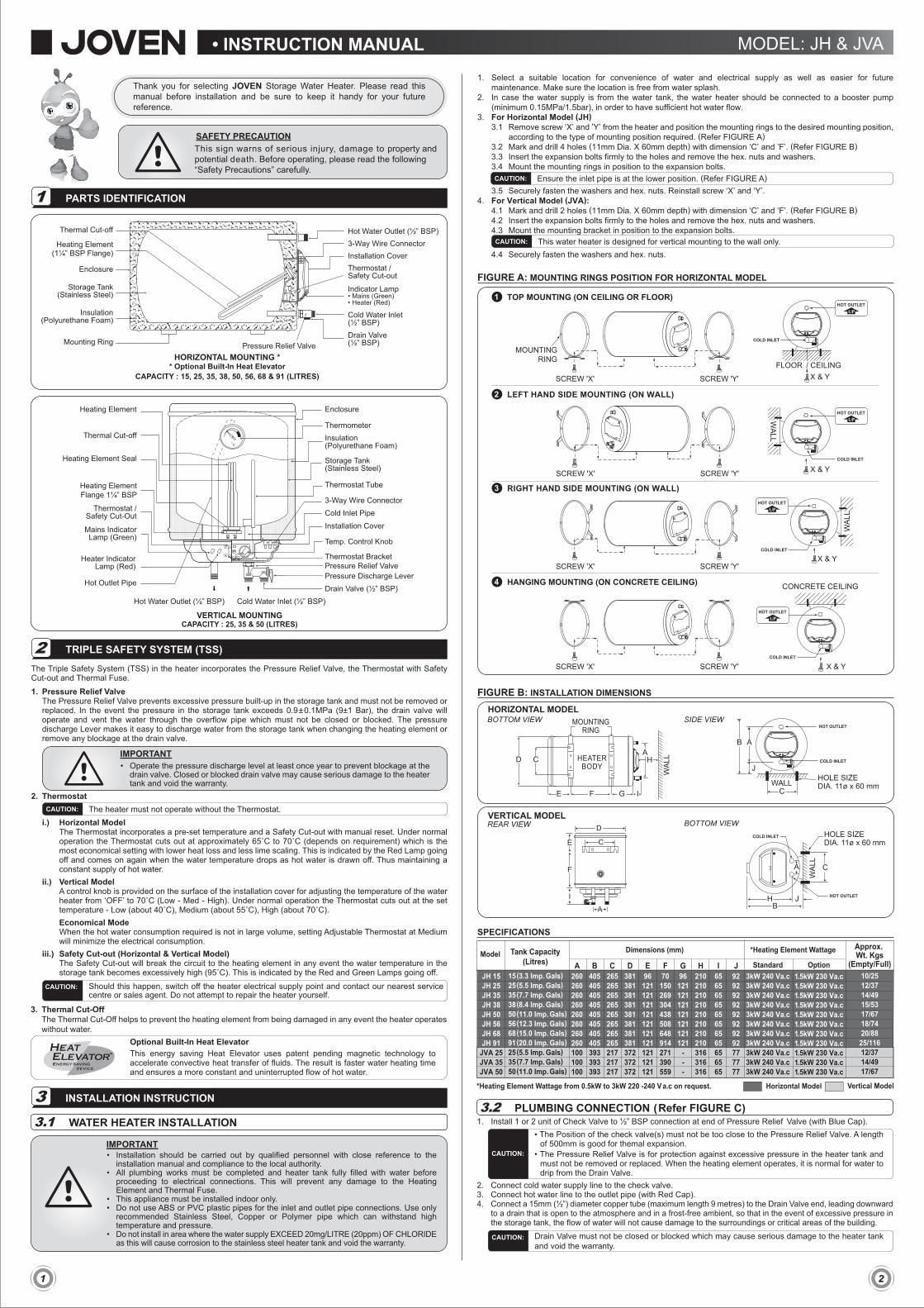
FIGURE C: PIPING DIAGRAM
A. Cold Water Inlet from Main Supply / Water TankB. Control Valve (Not Included)C. Single or Double Check Valve (Not included)D. Pressure Relief Valve
E. Drain Valve (Must not be closed / blocked)F. Overflow Pipe to Drain or floor trapG. Hot Water Outlet to Mixer Tap
min 500mm
A
B
F
C
G
DE
Refer to Figure Afor Mounting Ring Positionmin 500mm
A B
F
C
G
DE
© c
opyr
ight
01/
2012
-02
JOVE
N
PRODUCT WARRANTY9
TROUBLESHOOTING8
MAINTENANCE7
SCHEMATIC WIRING DIAGRAM5
WIRING CONNECTIONS4
OPERATION6
1. This warranty does not cover lightning, natural disaster, pest attacks, fire, negligence, misuses, accidents, floods, pollution, abuse or neglect, improper installation or improper maintenance and abnormal voltage or the usage of generator.
2. Failure to follow the installation manual.3. Repair or attempted to repair this product by anyone not authorised by JOVEN. 4. Any unit which has been altered or on which the serial number has been defaced, modified or removed.5. Water supply exceed 20mg/litre (20ppm) Chloride.
WARRANTY VOID
* Note: Refer to your local distributor for warranty terms & conditions
NEVER TRY TO REPAIR THE UNIT YOURSELF.IMPORTANT
SYMPTOMSA. No water coming out of the heater
B. Water heater is not working
C. Water not hot enough
POINT TO CHECK FOR REMEDY1. Check the following points for better performance:
• Check whether all stop valves are opened.• Check whether the water supply is there.• Check whether the Pressure Relief valve over tighten.• Check whether Inlet water supply connected to Pressure Relief Valve.• Check whether power supply is ON.• Is the main lamp ON.• Is the heater lamp ON.• Is the adjustable temp. control ON. (JVA model)• Is the mixer tap connected correctly.
• Is the adjustable temp. control turn to maximum. (JVA model)• Is the mixer tap adjusted correctly.• Is the water heater given enough time to heat up. (If the temp. reaches the
preset temp., the red heater lamp will go OFF automatically).• Is the water heater capacity enough for the purpose
2. If any of the following abnormalities are present during usage, contact our service centres nearest to you or your sales agent immediately:
A. Water leakage. B. Water temperature cannot be controlled (JVA model). C. Power and heater lamp does not light up.
Connect Overflow pipeleading downward to drain or floor trap
DO NOT connect overflow pipe leading upward
DO NOT Close or Block Drain Valve
DO NOT connect overflow pipe to any valve
OUT IN
IN INININ
Sealed
OUT IN OUT IN OUT IN
• All plumbing works must be completed and heater tank filled with water before proceeding to electrical connections. This will prevent any damage to the unit.
• Ensure that the electrical supply is single-phase at 220 to 240 Va.c.• It is recommended to install an approved current operated type Earth Leakage Circuit Breaker
(ELCB) or Residual Current Circuit Breaker (RCCB) of 10mA sensitivity and higher than heater rated current. (Refer to Table 1)
• It is recommended to install an approved type Miniature Circuit Breaker (MCB) or Molded Case Circuit Breaker (MCCB) higher than heater rated current. (Refer to Table 1)
• Ensure that the wiring can supply the necessary amperage. (Refer to Table 1 for correct cable size)• This water heater must be permanently connected to the electrical supply through a Double Pole
Linked Switch above rated current (Refer to Table 1) and having contact separation of at least 3mm in all poles incorporated in the fixed wiring. The switch must be out of reach from user in the bathroom.
• Do not share the electrical supply with other appliances.• Do not switch ON if there is a possibility that the water in the heater is frozen.• THIS APPLIANCE MUST BE PERMANENTLY EARTHED.
IMPORTANT
• Make sure the heater tank is filled with water before switching on the electrical supply. Failure to do so will damage the heating element and void the warranty.
• To avoid the danger of scalding when operating this water heater, always turn on the cold water faucet first and then adjust the hot water faucet to get the desired water temperature.
• This appliance is not intended for use by young children or infirm persons without supervision.
IMPORTANT
• After the maintenance, make sure the heater tank is completely refilled with water before switching on the electrical supply. Heating element will be damaged if electrical supply is switched on for even a short time while heater tank is dry or filling.
• Use any household cleaner for cleaning. Do not use abrasive cleaner or organic cleaner (petrol or alcohol).
IMPORTANT
Fig. 1 : Recommended Electrical Connection Fig. 2 : Recommended Stripping Length
12mm Copper Wire
PVC CableMCB / MCCB10mA ELCB / RCCB
Double Pole Linked Switch
Table 1 : Electrical Loading TablePower(kW)
Voltage(Va.c.)
ConductorSize (mm2)
Cable No.(No./Ømm)
Rated Current for Circuit Breaker / Double Pole Linked Switch (A)
1.37 to 1.632.50 to 3.00
220 to 240220 to 240
40/0.2570/0.25
1620
2.02.5
This water heater is completely factory wired to 3-way Connector with L(LIVE), N(NEUTRAL) and (EARTH) marking.1. Switch off the electrical mains.2. Remove installation cover screws of the heater.3. Refer to Fig. 2, connect electrical wire as follow: Brown to L (LIVE) Blue to N (NEUTRAL) Green / Yellow to (EARTH)4. Ensure that the copper wires are properly tightened on the 3-way Connector.5. Replace the installation cover.6. Provide sticker label if two heater ON / OFF switches are used to control it.
HORIZONTAL MODEL
HEA
TIN
G E
LEM
ENT
MAINS (GREEN INDICATOR)
NC THERMOSTAT
THERMALFUSE
3-WAYCONNECTOR
MAINSSUPPLY220-240 Va.c
NCNC
NNA
A
HEATER(RED INDICATOR)
Sealed
JVA
The first operation and heating of the appliance must be observed by the installing technician after water and electrical connection have been made and heater tank filled with water, before switching on the electrical supply.
The standard 3kW heating element (optional 1.5kW) together with automatic regulating thermostat (horizontal model) and an adjustable thermostat (vertical model), heat up water faster and keeps electric consumption to a minimum. In addition, the compact polyurethane foam insulation keeps the hot water longer and ready for immediate use.
• Approximate time taken to heat up to 70˚C. Inlet water temperature at 27˚C.STORAGE WATER HEATER HEATING CHART
MODEL Tank Capacity (Litres) Time Taken (Min) Replacement Rate43˚C Rise
3 kW 240 V a.c Heating Element - 63 litres (14 gals) per hour
1.5 kW 230 V a.c Heating Element - 32 litres (7 gals) per hour
3kW 240 Va.c 1.5kW 230 Va.cJH 15JH 25JH 35JH 38JH 50JH 56JH 68JH 91
JVA 25JVA 35JVA 50
1520303545506080203045
2340607090100120160406090
15 (3.3 Imp. Gals)25 (5.5 Imp. Gals)35 (7.7 Imp. Gals)38 (8.4 Imp. Gals)50 (11.0 Imp. Gals)56 (12.3 Imp. Gals)68 (15.0 Imp. Gals)91 (20.0 Imp. Gals)25 (5.5 Imp. Gals)35 (7.7 Imp. Gals)50 (11.0 Imp. Gals)
Horizontal Model Vertical Model
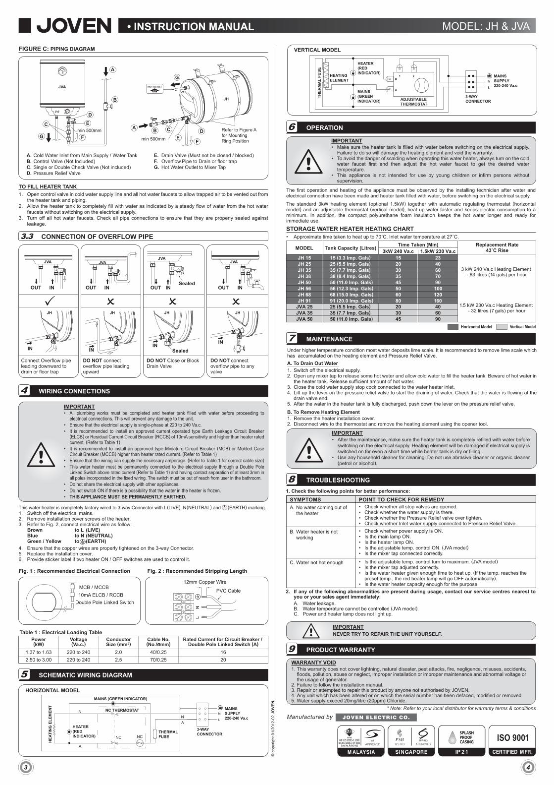
VERTICAL MODEL
A
BHEATINGELEMENT
THER
MA
L FU
SE
ADJUSTABLETHERMOSTAT
MAINS (GREEN INDICATOR)
1 2
3-WAYCONNECTOR
MAINSSUPPLY220-240 Va.c
HEATER(RED INDICATOR)
Under higher temperature condition most water deposits lime scale. It is recommended to remove lime scale which has accumulated on the heating element and Pressure Relief Valve.A. To Drain Out Water1. Switch off the electrical supply.2. Open any mixer tap to release some hot water and allow cold water to fill the heater tank. Beware of hot water in
the heater tank. Release sufficient amount of hot water.3. Close the cold water supply stop cock connected to the water heater inlet.4. Lift up the lever on the pressure relief valve to start the draining of water. Check that the water is flowing at the
drain valve end.5. After the water in the heater tank is fully discharged, push down the lever on the pressure relief valve.
B. To Remove Heating Element1. Remove the heater installation cover.2. Disconnect wire to the thermostat and remove the heating element using the opener tool.
JVA
JH
JVAJVA JVA
JH JH JH JH
MS IEC 60335- 1: 2005MS IEC 60335- 2- 21: 2005
Cert. No. PJ001402
IP 2 1