instruction manual - petitrcsite.petitrc.com/reglages/serpent/setup/748e/748e_manual.pdf · in...
TRANSCRIPT
INSTRUCTION MANUAL& REFERENCE GUIDE
INTRODUCTIONThe Serpent Natrix 748e is based on the successful Natrix 748 gaspowered car ( worlds TQ and Vice champion) , combining ultimate performance into a single package. The 200mm wide electric powered racing car offers superb handling with the durability of a stronger 200mm car.
The Serpent Natrix 748e is designed to be a world champion, while still being easy to use, assemble, and set up. You are now part of the worldwide network of Serpent drivers, which gives you superior technical support and access to many benefits that only Serpent drivers can enjoy.
The Serpent Natrix 748e offers state of the art specifications and leads the way in 200mm chassis design, using all the knowledge we have from 1/10 and 1/8 scale racing into this design too. Continuously pushing the performance envelope, Serpent’s engineers have added many new and innovative features that can help take your Serpent 748-e into the winner’s circle. Enjoy racing !
Team Serpent
INSTRUCTIONSSerpent’s long tradition of excellence extends to the instruction manuals, and this instruction manual is no exception. The easy-to-follow layout is richly illustrated with 3D-rendered full-color images to make your building experience quick and easy. Following the instructions will result in a well-built, high-performance race-car that will soon be able to unleash its full potential at the racetrack.
INSTRUCTIONS, hOw TO USe The kit includes bags, with bagnumbers, which refer to the same step in the manual. Open only the indicated bag(s) per step and finish that part of the assembly. Remaining parts will be needed lateron in the assembly process.
SeTUPIn certain assembly steps you need to make basicadjustments, which will give you a good initial setup for your Serpent S120–LTR. Fine-tuning the initial setup is an essential part of building a high-performance racecar like yourS120–LTR.
eXPLODeD VIewS AND PARTS LISTThe exploded views and parts lists for the Serpent S120–LTR are presented in the Reference Guide section in the back of this manual. The exploded views show all the parts of a particular assembly step along with the Serpent part number. The parts lists indicate the part number andname of each part for easy reference when ordering.
CUSTOmeR SeRVICeSerpent has made a strong effort to make this manual as complete and clear as possible. Additional info may be published in our website: www.serpent.com or you
may ask your dealer or the Serpent distributor for advice, or email Serpent direct: [email protected]
The Serpent Facebook, Twitter and Youtube pages give additional means of support and communications. SAfeTyRead and take note of the ‘Read this First section’ before proceeding to assemble the car-kit. This car-kit is intended for persons aged 16 or older.
Read this first!- This is a highly technical hobby product, intended to be used in a safe racing environment. This car is capable of speeds in excess of 80 km/h or 50mph. Please follow these guidelines when building and operating this model.- Parental guidance is required when the builder/user of this car is under 16.- Follow the building instructions. If in doubt, contact your dealer or importer.- Be sure to use the proper tools when assembling the car. Always exercise caution when using electric tools, knives and other sharp objects.- Be careful when using liquids like lubrication oil, fuel or glue. Do not swallow.- Follow the manufacturer’s instruction in case you experience irritation after using the product.- Be careful when operating the car. Stay away from any rotating parts such as wheels, gears and transmission. Stay away from motor, engine and exhaust pipe system or speedo during and immediately after use, as these parts may be very hot. We advise to use protective hand cloves.- Only operate this car in a safe environment, like a special racing track or a closed parking lot. Avoid using this car on public roads, crowded places or near infants.- Before operating this car, always check the mechanical status of the car. Also check that the transmitter and receiver frequencies correspond and are not used by any other racer at the same time. Check that the batteries of the transmitter and receiver- are fully charged.- After use, always check all the mechanics of the car. We advise to clean the car immediately after use, and inspect the parts for wear or fractures.Replace when necessary. Do not use water, methanol, thinner or other solvents to clean the car.- Empty the fuel tank (depending on model) if needed and disconnect thereceiver battery.- Store the car in a dry and heated place to avoid corrosion of metal parts.- Avoid using this car in wet conditions as the water will cause corrosion onthe metal parts and bearings and these parts will cease to function properly.If driven in the wet, ensure that all the electric equipment is waterproofedand after use, that all moving parts are dried immediately.
CONTENTSfRONT DIffeReNTIAL ASSemBLy 4ReAR DIffeReNTIAL ASSemBLy 9TRANSmISSION ASSemBLy 6STeeRING ASSemBLy 9ReAR ASSemBLy 11fRONT ASSemBLy 14RCm ShOCKS ASSemBLy 19eLeCTRONICS ASSemBLy 20RefeReNCe GUIDe 22
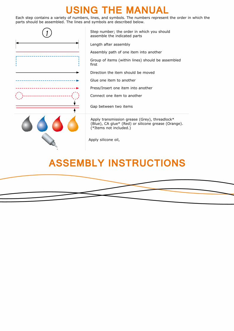
Length after assembly
Each step contains a variety of numbers, lines, and symbols. The numbers represent the order in which the parts should be assembled. The lines and symbols are described below.
Assembly path of one item into another
Group of items (within lines) should be assembled first
Direction the item should be moved
Glue one item to another
Press/Insert one item into another
Connect one item to another
Gap between two items
Apply transmission grease (Grey), threadlock* (Blue), CA glue* (Red) or silicone grease (Orange). (*Items not included.)
Step number; the order in which you should assemble the indicated parts1
USING THE MANUAL
Apply silicone oil,
ASSEMBLY INSTRUCTIONS

Page4
STEP
1
STEP
2
STEP
3
STEP
4
FRONT DIFFERENTIAL ASSEMBLY
NOTE: Add just enough oil to cover the large gear before assembling the small satellite gears and cross pins (step 3.3).
NOTE: 1) Assemble the o-ring before adding the oil.2) Add oil so the cross pins are just covered (DO NOT overfill).
BAG FRONT
DIFF
NOTE:In step 2 to mount the pin, first put the pin in the purpose made slot as shown, and after slide it through the hole in the shaft.
3.1
4.1 4.2
3.2
1.5x8
Use some grease during assembly
1.5x8
Use some grease during assembly
2
11
2
1
M2.5x10
NOTE: The diff assembled as shown here, should weigh max 17.1 grams

Page5
STEP
5
STEP
6
STEP
7
STEP
8
BAG REAR
DIFF
NOTE: Add just enough oil to cover the large gear before assembling the small satellite gears and cross pins (step 3.3).
NOTE: Step 5 and 6To mount the pin, first put the pin in the purpose made slot as shown, and after slide it through the hole in the shaft.
7.1
8.1 8.2
7.2
1.5x8
Use some grease during assembly
1.5x8
Use some grease during assembly
2
1
1
2
1
M2.5x8
REAR DIFFERENTIAL ASSEMBLY
NOTE: 1) Assemble the o-ring before adding the oil.2) Add oil so the cross pins are just covered (DO NOT overfill).
NOTE: The diff assembled as shown here, should weigh max 19.2 grams
Page6
M3x8
M3x8M3x8
12
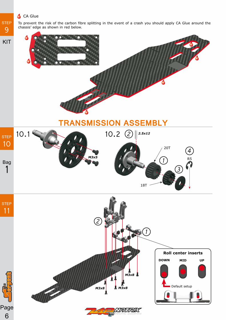
10.1 10.2
To prevent the risk of the carbon fibre splitting in the event of a crash you should apply CA Glue around the chassis’ edge as shown in red below.
CA Glue
KIT
M3x5
2.5x12
20T
R5
18T
STEP
9
STEP
10
STEP
11
1
2
3
4
TRANSMISSION ASSEMBLY
Bag
1
Roll center inserts
DOwN mID UP
Default setup

Page7
STEP
12
M3x10
STEP
13
M3x12
M3x6
M3x6
M3x6
M3x6
M3x6
1
2
3
1
2
5x8x2.5
5x8x2.5
Bag
2
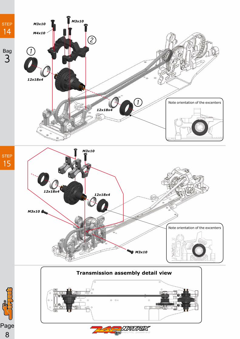
Page8
Transmission assembly detail view
M3x10M3x10
M3x10
M3x10
M3x10
M4x10
1
12
12x18x4
12x18x412x18x4
12x18x4
Note orientation of the excenters
Note orientation of the excenters
STEP
14
STEP
15
Bag
3

Page9
STEP
16
STEP
1717.1
M3x6
M3x10
M3x6
17.3
M3x6
M3x5
M3x8
M3x8
3x5x1
3x5x1
3x5x1
3x5x1
1
2
3
NOT INCLUDeD
M3x6
M3x6
STEERING ASSEMBLY16.1 16.2
M3x8
M3x6
4x7x2.5
4x7x2.5
17.2
8.5 mm
Use the following servo horns with this brand of servos: 23 - Sanwa / KO/ JR24 - Hitec25 - Futaba / Hitec/ Savox
Bag
4
1 mm
Servosaver ackerman inserts
fORwARDNARROw
fORwARDwIDe
ReARwARDNARROw
ReARwARDwIDe
Default setup

Page10
M3x16
5x8x2.5
8x5x2.5 Flanged
18.118.2
STEP
18
M3x6
M3x6M3x6
M3x6
M3x6M3x6
M3x6
STEP
19
17.4
M3x12
3x7x7 3x7x7

Page11
STEP
20
REAR ASSEMBLYM3x4
M3x8
M3x10
M3x123x6X3
3X5X1
STEP
21
STEP
22
1mm
1mm
10 mm 22.1
22.2
Bag
5

Page12
5x8x2.5
23.1
23.2
10x15x4
10x15x4
2x10
M3x3
24.1
24.2
1
1
3 4
STEP
23
STEP
24
M3x3
M3x3
M3x3
4.4mm
3mm
Bag
6

Page13
STEP
25
25.2
25.1
1
2
3
4 5
6.8 mm
M3x16
M3x10M3x6
M3x6
M3x16
Note the position in the rear camber link
STEP
26
M3x10
M3x10
M3x10
2x10
2x10

Page14
STEP
27
STEP
28
M3x4
M3x4
M3x12
1mm
1mm 1mm3.2x7x0.5
27mm
STEP
29 29.1
M3x3
FRONT ASSEMBLY
Bag
7

Page15
STEP
30
M3x3
M3x3
M3x10
3.2x7x0.5 3.2x7x0.5
M3x10
29.2
Front anti-roll bar detail view
Front suspension brackets up
INSIDe OUTSIDemID
Default setup

Page16
STEP
31
STEP
32
4mm
1mm
2mm
2mm
Note the position of the caster shimsM3x4
1
2
3
M3x10
3.2x7x0.5
Nylock nut M3
New 748 steering blocks introduce a new setting possibility, running neutral, trailing or leading position.
Leading position
Leading position
Trailing position
Trailing position
LefT SIDe
RIGhT SIDe
32.1
Bag
8
INITIAL SETTING:RIGHT AND LEFT NEUTRAL CONFIGURATION
STeeRING BLOCKS INSeRTS
fORwARD BACKwARDmID

Page17
M3x32x10
2x10
10x15x4
10x15x4
M3x6 M3x5
32.2
32.31
11
2
2
4 3
STEP
33
STEP
34
5.4mm
5.2mm
34.1
34.2
27.2 mm

Page19
Use someLocktiteto fix the nut
Use someoil during assembly
Close the topof the shock
Use someoil during assembly
11mm
Pull shockrod to bottom position before to fill the shock body with the supplied shock absorber oil..
BLeeDINGSlowly move the shockrod up and down to let all airbublesescape.
After assembly ensure you can push the piston all the way in (top of balljoint should hit the shock-bottom). If not, re-open the shock and let some oil bleed out, and repeat the steps.
Allow some ‘rebound’ on the shockshaft, around 4mm is normal.
RCM SHOCK ASSEMBLYSTEP
35 35.1 35.2
35.3 35.4
Nut M2.5
2.5x6x0.5
Check the default set-up sheet for the correct piston to use
Measure fully
extended
35.5 35.6
1
2
Insert the o-ring inside the spring-nut
Assemble the spring-nut
35.7
Assemble the spring and springcup to complete the shock
3
Bag
9

Page18
STEP
36
STEP
37
STEP
38
M3x8
M3x10
Nylock nut M3
1
2
M3x10
3.2x7x0.5
M3x10
M3x8
M3x6
M3x6
M3x8
1
12
3
2x10
2x10
Bag
10
Page20
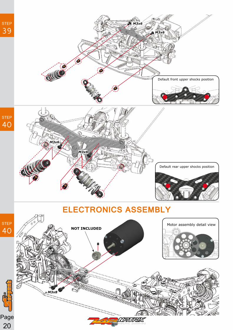
STEP
39
STEP
40
M3x6
M3x6
M3x6
M3x6
ELECTRONICS ASSEMBLY Motor assembly detail view
M3x8
NOT INCLUDeDSTEP
40
Default front upper shocks position
Default rear upper shocks position

Page21
STEP
41
STEP
42
STEP
43
NOT INCLUDeD
NOT INCLUDeD
NOT INCLUDeD
Tip: Use double sided tape to mount the ESC to the chassis, and RX to the top part of the servo (if there is not enough space on the chassis).
1
2
3
M3x12
M3x12
3x5x2
3x5x2Nylock nut M3
Nylock nut M3
M4 Flanged
M4 Flanged

Page22
REFERENCE GUIDE
Page23
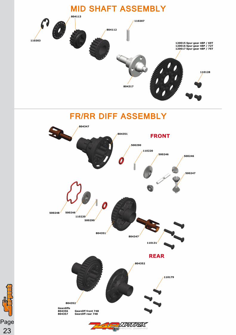
MID SHAFT ASSEMBLY
110303
804113
804112
110207
804317
120015 Spur gear 48P / 69T 120016 Spur gear 48P / 72T 120017 Spur gear 48P / 75T
110128
FR/RR DIFF ASSEMBLY804347
500248 500246
500290
804351
804352
804347
110131
110220
804351
804352
110179
500290
110220500246
500246
500247
fRONT
ReAR
Geardiffs 804356 Geardiff front 748 804357 Geardiff rear 748

Page24
11
01
24
11
04
09
80
43
18
11
01
22
11
01
08
11
01
00
11
01
04
11
01
04
11
01
04
11
01
24
80
43
35
11
01
24
11
01
04
80
41
57
16
52
80
41
54
11
01
57
11
01
22
11
01
27
80
43
13
80
41
70
80
43
33
40
14
13
13
46
13
46
80
41
53
80
41
53
80
43
34
80
43
16
80
42
80
80
42
19
80
41
52
80
41
52
80
41
68
80
43
12
11
01
09
11
01
09
11
01
09
13
38
13
38
40
13
99
40
13
99
11
01
22
11
01
22
80
43
36
11
01
08
11
01
08
11
01
08
11
01
08
80
43
80
80
43
24
41
12
53
40
11
34
80
43
37
41
12
53
11
01
22
40
11
34
80
41
30
80
41
24
80
43
11
80
41
29
80
41
52
80
41
33
13
46
13
46
11
01
09
80
43
79
80
41
02
11
01
00
11
01
20
11
01
22
11
01
22
11
01
22
11
01
27
41
12
06 9
02
13
8
11
04
09
TRANSMISSION-STEERING ASSEMBLY
80
43
10
13
12
90
12
55
13
11
11
01
10

Page25
REAR ASSEMBLY
80
31
98
11
01
16
80
12
19
11
02
08
80
41
46
16
47
90
32
31
11
01
31
80
42
82
80
23
32
13
44
13
44
80
12
18
80
42
81
80
42
81
80
42
81
80
82
14
11
01
00
11
01
24
11
02
08
11
02
08
11
01
24 80
43
06
11
01
24
80
22
11
41
12
07
90
21
38
90
32
31
80
23
39
11
01
16
90
33
34
80
22
11 11
01
24
80
41
16
16
52
11
01
09
11
04
09
11
01
17
11
04
17
41
12
53
80
12
15
90
32
31
80
41
40
16
52
11
01
08
11
01
09
80
43
42
90
21
38
80
42
20
11
01
16 1
31
1
Page26
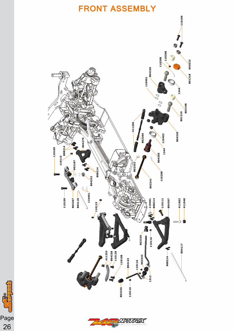
FRONT ASSEMBLY
80
32
41
80
23
52
11
02
08
11
02
08
11
02
08
41
12
06
80
22
60
80
12
18
11
01
09
11
01
09
80
82
14
80
82
14
11
01
15
90
31
87
80
42
79
11
01
09
41
12
53
80
43
38
11
01
28
11
01
08
80
42
67
80
41
18
11
04
01
11
04
01
80
43
32
80
42
05 13
44
13
44
80
43
20
80
43
20
11
04
01
90
35
23
11
04
02
80
12
19 80
31
98
11
01
15
11
01
16
90
33
43
80
41
17
41
10
48
41
10
63
80
42
07
11
01
12
80
23
35
80
23
35
80
41
43
11
01
16
11
01
16
13
12
80
82
14
80
82
14
Page27
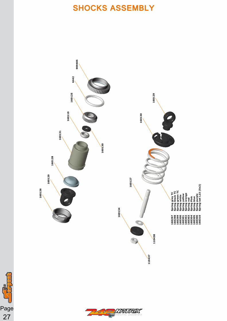
16
01
26
11
04
37
16
01
34
11
04
38
16
01
27
16
02
97
S
pri
ng
gre
y TC
16
02
98
S
pri
ng
bla
ck T
C1
60
29
9
Sp
rin
g g
reen
TC
16
03
00
S
pri
ng
wh
ite
16
03
01
S
pri
ng
yel
low
16
03
02
S
pri
ng
ora
ng
e1
60
30
3
Sp
rin
g r
ed1
60
30
4
Sp
rin
g P
ink
16
03
05
S
pri
ng
blu
e1
60
30
6
Sp
rin
g p
urp
le1
60
31
0
Sp
rin
g-s
et L
23
(5
x2)
16
01
30
16
01
29
16
01
29
16
01
28
16
01
31
16
01
10
16
01
30
16
01
25
64
42
90
94
05
SHOCKS ASSEMBLY
Page28
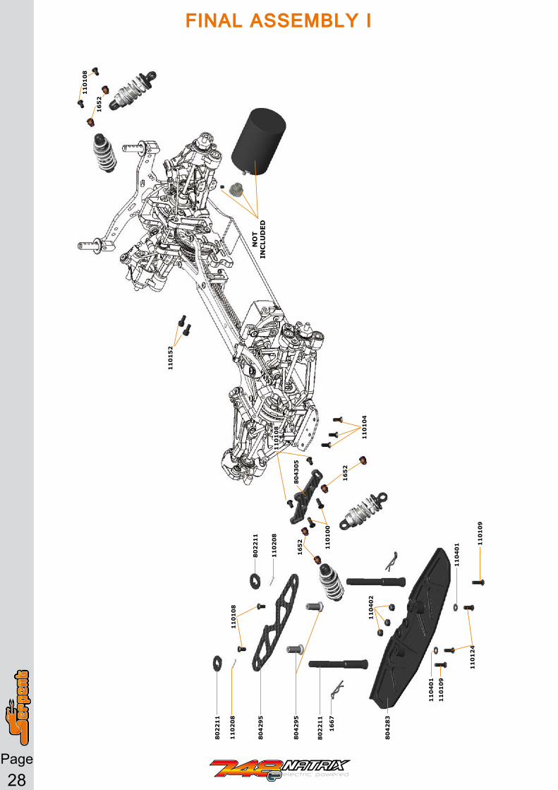
80
42
83
16
52
16
52
80
22
11
80
22
11
80
42
95
11
01
08
11
01
08
11
02
08
11
02
08
11
01
00
16
67
80
22
11
80
42
95
11
01
09
11
01
09
11
04
01
11
04
01
11
01
24
80
43
05
11
01
04
11
04
02
16
52
11
01
08
11
01
52
NO
T IN
CLU
DeD
FINAL ASSEMBLY I

Page29
11
04
10
11
04
05
11
01
27
11
01
27
80
43
09
11
04
02
14
94
11
04
02
FINAL ASSEMBLY II

Page30
TEAM SERPENT NETWORK
WEbSiTE ANd blOg
NATRiX 748e SPARES
NATRiX 748e OPTiONAlS
SERPENT TOOlS
SERPENT MERCHANdiSiNg
SOCiAl MEdiA

Page31
NEWS / NOTES