instruction manual impact67-p - murrelektronik · v 1.6 1 instruction manual instruction manual for...
TRANSCRIPT

Configuration
Installation
Startup
Diagnostics
Technical Data
||
||
||
||
||
||Instruction Manual IMPACT67-P
V 1.6 1
Instruction Manual Instruction Manual for Devices from the IMPACT67-P For use with GSD Version 1 and HW Version 1 Article Number 55 345, IMPACT67-P DI16 Article Number 55 346, IMPACT67-P DI8/DO8 Article Number 55 347, IMPACT67-P DO8 Article Number 55 348, IMPACT67-P DO16
Publisher's Note Instruction manual for devices from the IMPACT67-P product line, Article Number 55364 Version 1.6 Present version dated Jan 19, 2011 Murrelektronik GmbH Falkenstrasse 3 D-71570 Oppenweiler Tel. +49 7191 47-0 Fax +49 7191 47-130 [email protected]
IMPACT67-P manual
2 V 1.6
Contents
Important Information
Typographical Conventions This manual contains important notes that you should observe to guarantee your own safety and avoid material damage. These notes are marked in a special way as follows:
The texts of special notes refer to important information.
Danger notices refer to information that, if you fail to observe, may result in damage to equipment and other objects or, if appropriate precautions are not taken, may result in danger to the user's health or life.
Intended Purpose Read this manual carefully before starting the equipment and keep it in a place that is accessible at all times for all users. The products described in this manual were developed, manufactured, tested, and documented under strict compliance with safety standards. Normally, the products pose no danger to persons or property, provided the handling specifications and safety instructions contained in this manual are observed. The products meet the requirements of the European EMC Directive (89/336/EEC) and the European Machine Directive (98/37/EEC). The products are designed for use in industrial environments. A feature of the industrial environment is that consumers are not directly connected to the public low-voltage power network. Extra precautions are required for use in residential, business, and commercial applications. Troublefree and safe functioning of the product can only be assured through proper transportation, storage, installation, assembly, and operation with proper care and attention. Use of the device for its intended purpose is only assured if the housing is fully mounted.
Excellent resistance to chemicals and oils. Before use with aggressive media, check the resistance of the materials to the application.

V 1.6 3
The power supply must correspond to SELV1 or PELV2 standards. Power supplies as per EN 61558-2-6 (transformer), or as per EN 60950-1 (switched-mode power supply), meet this requirement. System configuration, installation, startup, maintenance, and testing of devices may only be performed by an accredited, trained electrician familiar with automation technology safety standards. The safety and accident prevention regulations valid for specific applications must be observed during the configuration, installation, startup, maintenance, and testing of devices. Only cables and accessories may be installed, provided they conform to the requirements, regulations, and specifications for safety, electromagnetic compatibility, and, where applicable, telecommunications terminal equipment. Information regarding cables and accessories approved for installation can be obtained from the Murrelektronik subsidiary in your region, and may also be found in this manual.
Qualified Personnel The requirements for qualified personnel are based on requirements profiles defined by ZVEI and VDMA. Only trained electricians who are familiar with the contents of the following manual may install and service the described products: "Weiterbildung in der Automatisierungstechnik" (Further Training in Automation Engineering), published by ZVEI and VDMA in the Maschinenbau-Verlag, Postfach 710864 in 60498 Frankfurt, Germany. These are persons who are capable of assessing the work to be done and the possible dangers on account of their technical training, knowledge, experience, and knowledge of the relevant standards; or who have an identical level of knowledge equivalent to technical training since they have worked in the same area for many years. Only Murrelektronik technical staff is allowed to make interventions in the hardware and software of our products.
Unqualified alteration of hardware or software, or failure to heed the warnings given in the manual, may result in severe personal injury or damage to property.
1 Safety Extra Low Voltage 2 Protective Extra Low Voltage

IMPACT67-P manual
4 V 1.6
1. Configuration 1.1 Power Supply
Bus modules require a direct-voltage power supply of typically 24 VDC (SELF/PELF) which must comply with the regulations of conventional industrial power-utility companies.
In order to optimize immunity from interference, we advise you to power sensors, bus, and actuators from different sources. The power supply should be primary switched-mode or regulated power supplies.
The output of the power supply units is dependent on the number of connected electrical consumers and their output.
In any case, it must be ensured that the system voltage does not drop below 18 VDC viewed from the system power supplies and measured at the remotest slave. System response becomes unspecific if sensor and bus power supply drops below 18 VDC.
Primary switched-mode power supply units normally permit an increase in output voltage to the amount of the rated voltage in order to compensate for any power losses.
Modules with digital inputs support the direct connection of commercially available sensors. A separate power supply may be necessary for the sensors if the total power requirement is high due to the number of slaves or the sensors have a high power draw.
Recommended "MCS Power" power supply units Primary switched-mode power supply units from the MCS Power series are specially designed to power automation systems. For this reason, we recommended them to power the modules.
Please refer to our accessory information on page 36.
Wire Cross-Sections The wire cross-section may be max. 1.5 mm². It is limited to this maximum cross-section by the 7/8“ connector.
V 1.6 5
1.2 Electromagnetic Compatibility (EMC)
This device meets the requirements of EC Directive 89/336/EEC "Electromagnetic Compatibility".
This device is Class A equipment and causes radio-frequency interference in residential areas. In this case, the operator may be required to implement adequate countermeasures.
The devices described in this manual each meet the relevant standards for electromagnetic compatibility. However, this does not mean that their electromagnetic compatibility is still guaranteed when fitted to a plant or machine. For this reason, we urgently advise you to comply with the instructions on installation in accordance with EMC requirements below. Only then can you assume that the overall system complies with EMC requirements, provided CE-marked components are used exclusively.
Protection Against Electrostatic Discharge The products described in this manual contain complex semiconductor components which may be destroyed or damaged by electrostatic discharge (ESD). Damage does not necessarily lead to immediate, detectable failure, or malfunction. These states may be even delayed, or occur sporadically. The generally accepted safety precautions for ESD sensitive devices must be observed when handling the devices. The following precautions in particular must be taken:
Never unplug or plug in connectors live. If you are an operator, discharge any static charge you may be carrying just before you touch equipment. For example, you can touch a grounded part of the machine, or wear an ESD discharge strap permanently connected to ground.
Grounding A short (as short as possible), low-impedance connection between the grounding point and the reference ground is essential to divert interference voltages running between the device and reference ground. The inductance of standard FE conductors is a high impedance for high-frequency interference voltages. For this reason, the use of grounding straps is advisable. If this is not possible, a fine-wire FE conductor should be selected with the largest possible cross-section, and the connection to ground should be kept as short as possible.
IMPACT67-P manual
6 V 1.6
Cable Routing You can avoid EMC problems by observing elementary basic rules of cable routing:
Route data lines as far away from power lines as possible. Route data lines and power lines at least 10 cm apart. Only intersect data and power lines at right angles. Route data and power lines in separate, shielded compartments. Remember the interference potential of other devices or lines when you route the cables. Place frequency converters, motor lines, and other devices and lines that emit high-
frequency interference at the greatest possible distance.
Blackouts and Brownouts Transient voltage cutoffs (<10 ms) normally pose no operational problems as the electronics are protected by capacitors integrated in the power circuits. This does not apply to the power supplies of the sensors and actuators connected to the module. Their high power requirement cannot be covered by the capacitors integrated in the device. For this reason, even transient interruptions in actuator voltage result in undesirable switching operations. Due to the integrated input filter, a change in the input signal of less than 1 ms leads to no change in the input state signaled to the Master. Longer interruptions in sensor supply may lead to input signal changes.
Separate Power Supplies Sensors or actuators can be powered by common power supply units. However, it is preferable to use separate power supplies in order to maximize the electromagnetic compatibility of the overall system.
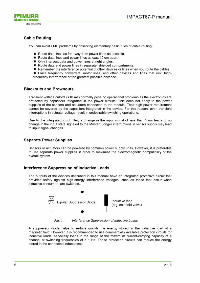
Interference Suppression of Inductive Loads The outputs of the devices described in this manual have an integrated protective circuit that provides safety against high-energy interference voltages, such as those that occur when inductive consumers are switched.
Fig. 1: Interference Suppression of Inductive Loads A suppressor diode helps to reduce quickly the energy stored in the inductive load of a magnetic field. However, it is recommended to use commercially available protection circuits for inductive loads, especially loads in the range of the maximum current-carrying capacity of a channel at switching frequencies of > 1 Hz. These protection circuits can reduce the energy stored in the connected inductances.
Bipolar Suppressor Diode Inductive load
(e.g. solenoid valve)

V 1.6 7
The high voltages that occur when inductive loads are shut down result in strong fields in the cables with consequential faults in adjacent circuits or devices.
Murrelektronik GmbH can supply you with a wide selection of interference suppression products for this purpose.
Please refer to our catalog or visit www.murrelektronik.com.
Other Measures and Limits In some system configurations, the requirements for interference emission and immunity from interference can only be met with additional measures, or even not at all. In these cases, the EMC within the system is also dependent on the single components of other manufacturers.
Mains filters are a suitable means of reducing line-conducted interference. Various manufacturers offer optical-fiber converters. This data transmission technology is
basically immune to EMC interference. However, this does not apply to the electronic conversion circuits. For this reason, the use of optical fibers does not solve all EMC problems.
Our certified test center is available to answer any further queries you may have on EMC. There, you will also receive advice on guaranteeing compliance with the EMC Directive for the systems you produce. Murrelektronik Test Center Grabenstrasse 27 71570 Oppenweiler Tel. 0049 7191 47-334 Fax 0049 7191 47-323 [email protected]

IMPACT67-P manual
8 V 1.6
1.3 Replaceability
IMPACT67-P modules can replace the phased-out MBV-P modules. This means that modules of identical type are physically replaceable. It is no problem to replace an MBV-P module with an IMPACT67-P module. Channel assignment and diagnostic messages are identical. It is also unnecessary to load a new GSD file. IMPACT67-P modules are capable of running with MBVP3101.gsd. The MURR3101.gsd file is available for new configurations, or for adapting an existing configuration to the current article numbers of IMPACT67-P modules. The table shows the replaceability in each case.
MBV-P Replaceable by IMPACT67-P
DI16 (55453/55483) DI16
(55345)
DI8/DO4 2A (55452/55482) DI8/DO8 2A
(55346)
DO8 2A (55451/55481) -
DO8 1.6A (55484)
DO8 2A (55347)
Table 1: Replaceability of the modules
V 1.6 9
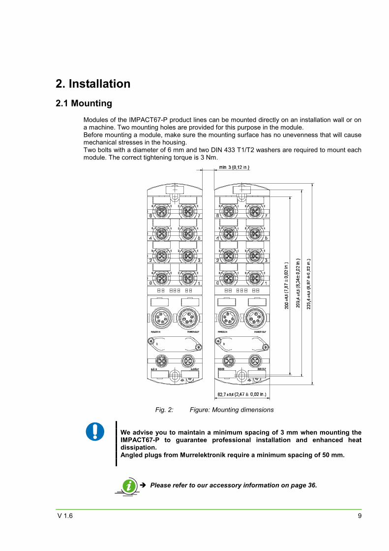
2. Installation 2.1 Mounting
Modules of the IMPACT67-P product lines can be mounted directly on an installation wall or on a machine. Two mounting holes are provided for this purpose in the module. Before mounting a module, make sure the mounting surface has no unevenness that will cause mechanical stresses in the housing. Two bolts with a diameter of 6 mm and two DIN 433 T1/T2 washers are required to mount each module. The correct tightening torque is 3 Nm.
Fig. 2: Figure: Mounting dimensions
We advise you to maintain a minimum spacing of 3 mm when mounting the IMPACT67-P to guarantee professional installation and enhanced heat dissipation. Angled plugs from Murrelektronik require a minimum spacing of 50 mm.
Please refer to our accessory information on page 36.
IMPACT67-P manual
10 V 1.6
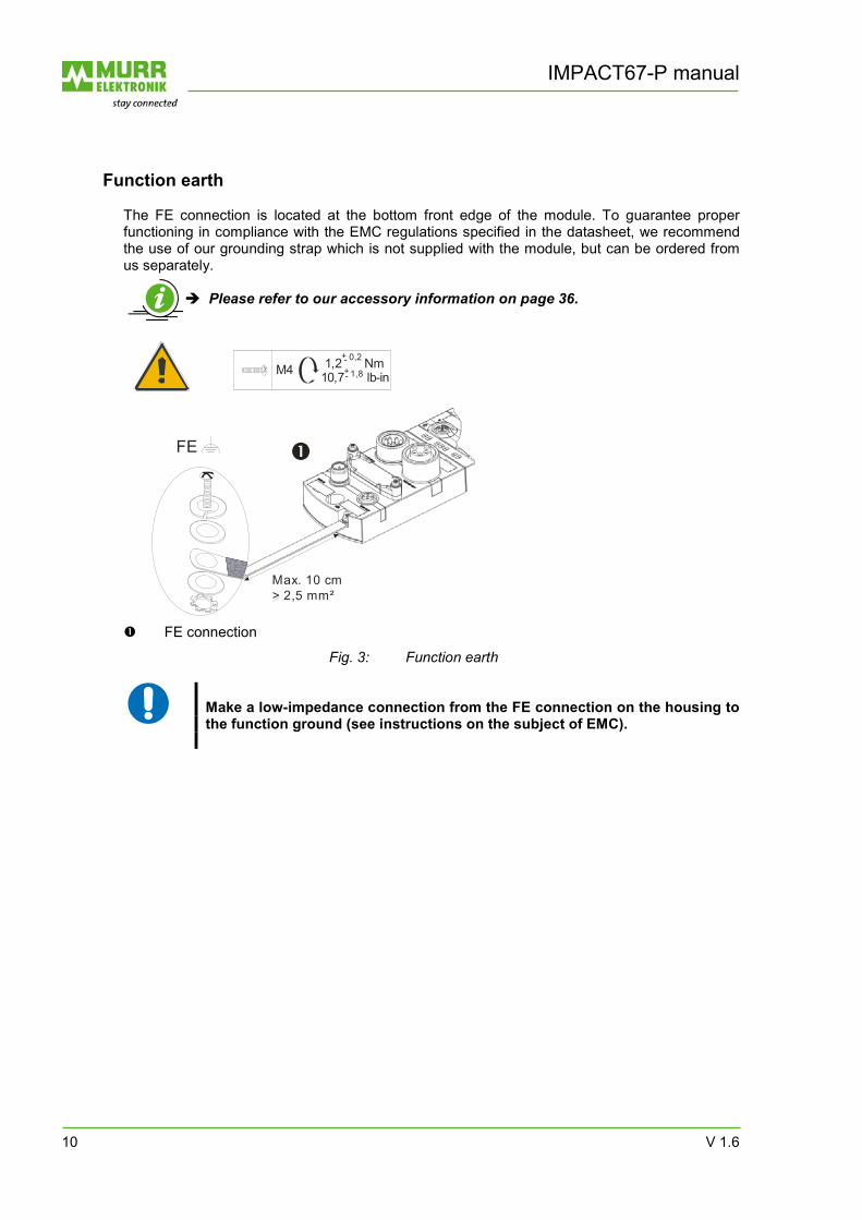
Function earth
The FE connection is located at the bottom front edge of the module. To guarantee proper functioning in compliance with the EMC regulations specified in the datasheet, we recommend the use of our grounding strap which is not supplied with the module, but can be ordered from us separately.
Please refer to our accessory information on page 36.
FE connection
Fig. 3: Function earth
Make a low-impedance connection from the FE connection on the housing to the function ground (see instructions on the subject of EMC).
10,7 lb-in1,2 Nm
+- 0,2+- 1,8M4
FE
Max. 10 cm> 2,5 mm²
V 1.6 11
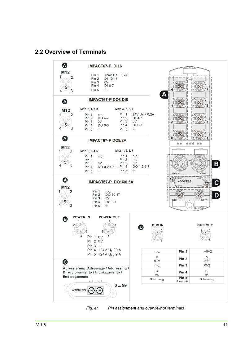
2.2 Overview of Terminals
Adressierung / Adressage / Addressing / Direccionamiento / Indirizzamento /Endereçamento :
0 ... 99x 10 x 1
ADDRESS
1
25
3
4 1
25
3
4
BUS IN BUS OUT
Pin 1
Pin 2
Pin 3
Pin 4Pin 5
n.c.
n.c.
Schirmung Gewinde
A grün
Brot
A
3
2
5
1
4
M12
IMPACT67-P DO16/0,5A
C
D
A
3
2
5
1
4
M12
Pin 3 0V Pin 4 DI 0-7
Pin 1 +24V Us / 0,2APin 2 DI 10-17
Pin 5
IMPACT67-P DI16
3
2
5
1
4
M12
Pin 3 0V Pin 4 DO 0-3
Pin 1 n.c.Pin 2 DO 4-7
Pin 5
IMPACT67-P DO8 DI8
IMPACT67-P DO8/2A
Pin 3 0V Pin 4 DO 0-7
Pin 1 n.c.Pin 2 DO 10-17
Pin 5
0, 1, 2, 3M12 , 5, 6, 7M12 4
Pin 3 0V Pin 4 DI 0-3
Pin 1 24V Us / 0,2APin 2 DI 4-7
Pin 5
Pin 3 0V Pin 4 DO 0,2,4,6
Pin 1 n.c.Pin 2
Pin 5
0, 2, 4, 6M12 , 3, 5, 7M12 1
Pin 3 0V Pin 4 DO 1,3,5,7
Pin 1 n.cPin 2 n.c
Pin 5
0V 0V
+24V US / 9 A
Pin 1Pin 2Pin 3Pin 4
POWER OUTPOWER IN
2
54
3
112
3 54
B
A
3
2
5
1
4
M12
A
+24V UA / 9 A Pin 5+5V2
0V2
Schirmung
A grün
Brot
Fig. 4: Pin assignment and overview of terminals
IMPACT67-P manual
12 V 1.6
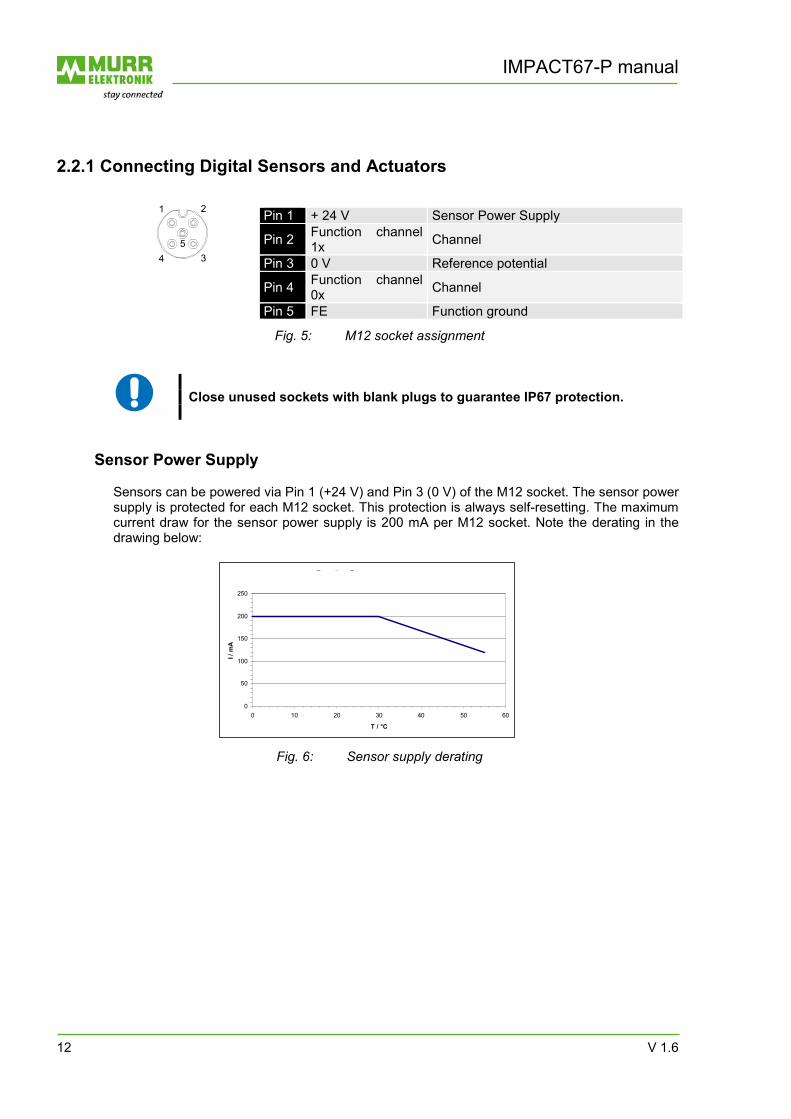
2.2.1 Connecting Digital Sensors and Actuators
Pin 1 + 24 V Sensor Power Supply
Pin 2 Function channel 1x Channel
Pin 3 0 V Reference potential
Pin 4 Function channel 0x Channel
Pin 5 FE Function ground
Fig. 5: M12 socket assignment
Close unused sockets with blank plugs to guarantee IP67 protection.
Sensor Power Supply Sensors can be powered via Pin 1 (+24 V) and Pin 3 (0 V) of the M12 socket. The sensor power supply is protected for each M12 socket. This protection is always self-resetting. The maximum current draw for the sensor power supply is 200 mA per M12 socket. Note the derating in the drawing below:
Derating Sensorversorgung
0
50
100
150
200
250
0 10 20 30 40 50 60
T / °C
I / m
A
Fig. 6: Sensor supply derating
21
345
V 1.6 13
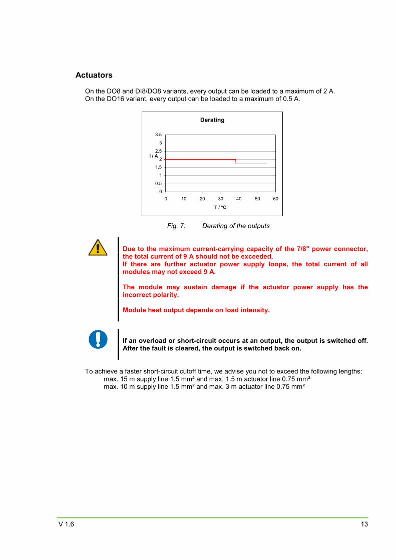
Actuators On the DO8 and DI8/DO8 variants, every output can be loaded to a maximum of 2 A. On the DO16 variant, every output can be loaded to a maximum of 0.5 A.
Fig. 7: Derating of the outputs
Due to the maximum current-carrying capacity of the 7/8" power connector, the total current of 9 A should not be exceeded. If there are further actuator power supply loops, the total current of all modules may not exceed 9 A. The module may sustain damage if the actuator power supply has the incorrect polarity. Module heat output depends on load intensity.
If an overload or short-circuit occurs at an output, the output is switched off. After the fault is cleared, the output is switched back on.
To achieve a faster short-circuit cutoff time, we advise you not to exceed the following lengths: max. 15 m supply line 1.5 mm² and max. 1.5 m actuator line 0.75 mm² max. 10 m supply line 1.5 mm² and max. 3 m actuator line 0.75 mm²
Derating
0
0.5
1
1.5
2
2.5
3
3.5
0 10 20 30 40 50 60
T / °C
I / A
IMPACT67-P manual
14 V 1.6
2.3 Wiring-Up 2.3.1 Wiring Up the Profibus
Cables The bus line must be designed to EN 50170 Part 2 (line type A). To ensure the simplest and most reliable wiring possible, we recommend using our Prewired Profibus lines.
Please refer to our accessory information on page 36.
Connecting to IMPACT67-P Connect function ground with FE connection to casing. Connect incoming Profibus cables to incoming bus terminal. Connect any continuing Profibus cables to continuing bus terminal or screw on terminating resistor to continuing bus terminal.
Each Profibus segment must be installed with a terminating resistor at start and end.
2.3.2 Connecting the Power Supply
The module may be damage if the power supply unit has the incorrect polarity. We therefore recommend you use our prewired 7/8 lines.
Connecting the Power Supply to the Module Auxiliary power is required to feed the actuators and sensors. The IMPACT67-P electronics are powered by the sensor power supply.
The sensor power supply should not be switchable.
The 7/8“ connector is designed for a maximum current of 9 A per pin. This must be considered if the power supply has additional loops.

V 1.6 15
3. Startup 3.1 Allocating and Setting the Profibus Address
The Profibus address is set directly on the IMPACT67-P by means of two BCD rotary switches. The permissible values range from 0 to 99. It is normal to assign address 0 to 2 to a DP master. For this reason, we advise you to start the address settings with Address 3 on IMPACT67-P.
The set address is read in once after the supply voltage is applied. Therefore, a change of address only takes effect after a module voltage reset. It is important to ensure that an explicit and unique address is assigned to each Profibus slave.
3.2 GSD File
IMPACT67-P modules are capable of running with MBVP3101.gsd. The MURR3101.gsd file is available for new configurations, or for adapting an existing configuration to the current article numbers of IMPACT67-P modules. The file extension denotes the language version. The GSD files are available in six languages.
Language File ending *.gsd Default = English *.gse English *.gsg German *.gss Spanish *.gsf French *.gsi Italian *.gsp Portuguese
Table 2: Language versions of the GDS-File The GSD file is available for download from the Murrelektronik website: www.murrelektronik.de
IMPACT67-P manual
16 V 1.6
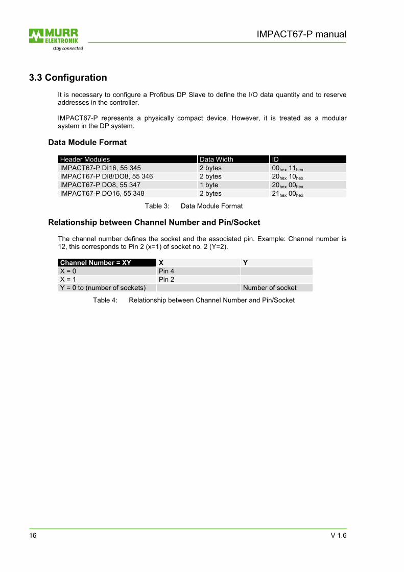
3.3 Configuration It is necessary to configure a Profibus DP Slave to define the I/O data quantity and to reserve addresses in the controller. IMPACT67-P represents a physically compact device. However, it is treated as a modular system in the DP system.
Data Module Format Header Modules Data Width ID IMPACT67-P DI16, 55 345 2 bytes 00hex 11hex IMPACT67-P DI8/DO8, 55 346 2 bytes 20hex 10hex IMPACT67-P DO8, 55 347 1 byte 20hex 00hex IMPACT67-P DO16, 55 348 2 bytes 21hex 00hex
Table 3: Data Module Format
Relationship between Channel Number and Pin/Socket The channel number defines the socket and the associated pin. Example: Channel number is 12, this corresponds to Pin 2 (x=1) of socket no. 2 (Y=2). Channel Number = XY X YX = 0 Pin 4 X = 1 Pin 2 Y = 0 to (number of sockets) Number of socket
Table 4: Relationship between Channel Number and Pin/Socket
V 1.6 17
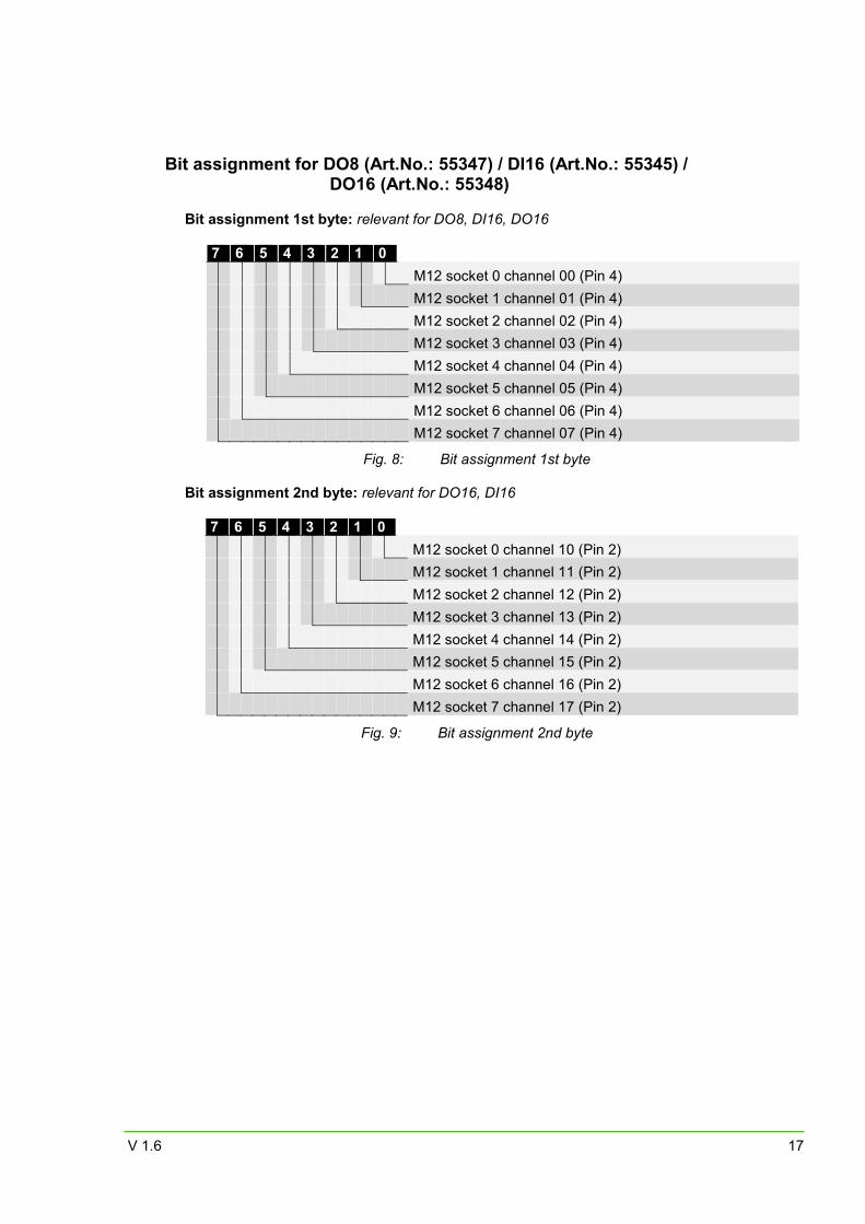
Bit assignment for DO8 (Art.No.: 55347) / DI16 (Art.No.: 55345) / DO16 (Art.No.: 55348)
Bit assignment 1st byte: relevant for DO8, DI16, DO16
7 6 5 4 3 2 1 0
M12 socket 0 channel 00 (Pin 4)
M12 socket 1 channel 01 (Pin 4)
M12 socket 2 channel 02 (Pin 4)
M12 socket 3 channel 03 (Pin 4)
M12 socket 4 channel 04 (Pin 4)
M12 socket 5 channel 05 (Pin 4)
M12 socket 6 channel 06 (Pin 4)
M12 socket 7 channel 07 (Pin 4)
Fig. 8: Bit assignment 1st byte Bit assignment 2nd byte: relevant for DO16, DI16
7 6 5 4 3 2 1 0
M12 socket 0 channel 10 (Pin 2)
M12 socket 1 channel 11 (Pin 2)
M12 socket 2 channel 12 (Pin 2)
M12 socket 3 channel 13 (Pin 2)
M12 socket 4 channel 14 (Pin 2)
M12 socket 5 channel 15 (Pin 2)
M12 socket 6 channel 16 (Pin 2)
M12 socket 7 channel 17 (Pin 2)
Fig. 9: Bit assignment 2nd byte
IMPACT67-P manual
18 V 1.6
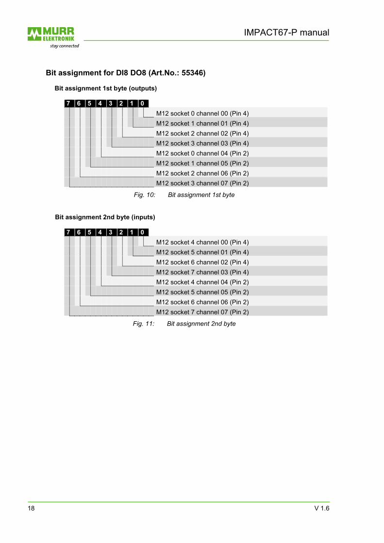
Bit assignment for DI8 DO8 (Art.No.: 55346) Bit assignment 1st byte (outputs)
7 6 5 4 3 2 1 0
M12 socket 0 channel 00 (Pin 4)
M12 socket 1 channel 01 (Pin 4)
M12 socket 2 channel 02 (Pin 4)
M12 socket 3 channel 03 (Pin 4)
M12 socket 0 channel 04 (Pin 2)
M12 socket 1 channel 05 (Pin 2)
M12 socket 2 channel 06 (Pin 2)
M12 socket 3 channel 07 (Pin 2)
Fig. 10: Bit assignment 1st byte Bit assignment 2nd byte (inputs)
7 6 5 4 3 2 1 0
M12 socket 4 channel 00 (Pin 4)
M12 socket 5 channel 01 (Pin 4)
M12 socket 6 channel 02 (Pin 4)
M12 socket 7 channel 03 (Pin 4)
M12 socket 4 channel 04 (Pin 2)
M12 socket 5 channel 05 (Pin 2)
M12 socket 6 channel 06 (Pin 2)
M12 socket 7 channel 07 (Pin 2)
Fig. 11: Bit assignment 2nd byte
V 1.6 19
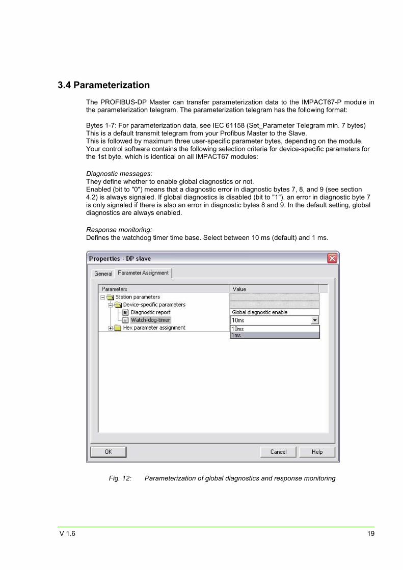
3.4 Parameterization
The PROFIBUS-DP Master can transfer parameterization data to the IMPACT67-P module in the parameterization telegram. The parameterization telegram has the following format:
Bytes 1-7: For parameterization data, see IEC 61158 (Set_Parameter Telegram min. 7 bytes) This is a default transmit telegram from your Profibus Master to the Slave. This is followed by maximum three user-specific parameter bytes, depending on the module. Your control software contains the following selection criteria for device-specific parameters for the 1st byte, which is identical on all IMPACT67 modules: Diagnostic messages: They define whether to enable global diagnostics or not. Enabled (bit to "0") means that a diagnostic error in diagnostic bytes 7, 8, and 9 (see section 4.2) is always signaled. If global diagnostics is disabled (bit to "1"), an error in diagnostic byte 7 is only signaled if there is also an error in diagnostic bytes 8 and 9. In the default setting, global diagnostics are always enabled. Response monitoring: Defines the watchdog timer time base. Select between 10 ms (default) and 1 ms.
Fig. 12: Parameterization of global diagnostics and response monitoring
IMPACT67-P manual
20 V 1.6
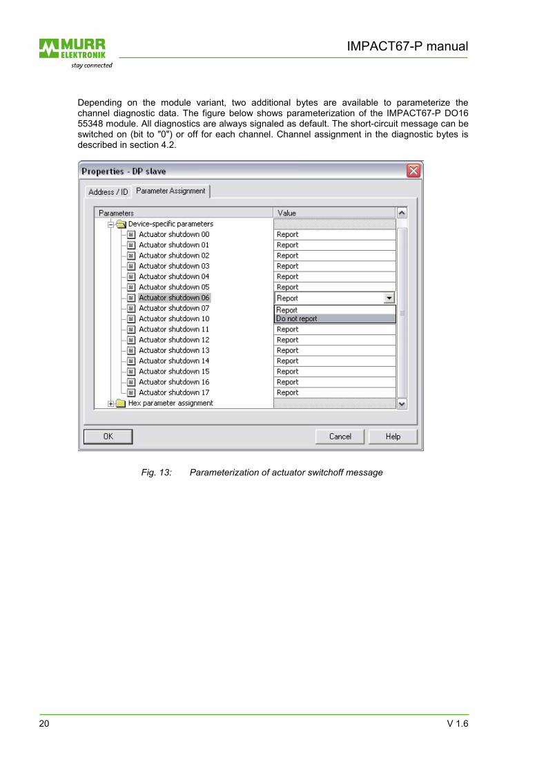
Depending on the module variant, two additional bytes are available to parameterize the channel diagnostic data. The figure below shows parameterization of the IMPACT67-P DO16 55348 module. All diagnostics are always signaled as default. The short-circuit message can be switched on (bit to "0") or off for each channel. Channel assignment in the diagnostic bytes is described in section 4.2.
Fig. 13: Parameterization of actuator switchoff message
V 1.6 21
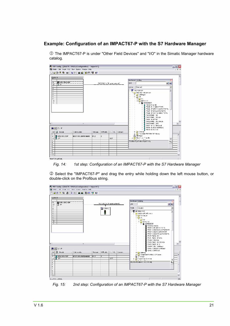
Example: Configuration of an IMPACT67-P with the S7 Hardware Manager
The IMPACT67-P is under "Other Field Devices" and "I/O" in the Simatic Manager hardware catalog.
Fig. 14: 1st step: Configuration of an IMPACT67-P with the S7 Hardware Manager
Select the "IMPACT67-P" and drag the entry while holding down the left mouse button, or
double-click on the Profibus string.
Fig. 15: 2nd step: Configuration of an IMPACT67-P with the S7 Hardware Manager
IMPACT67-P manual
22 V 1.6
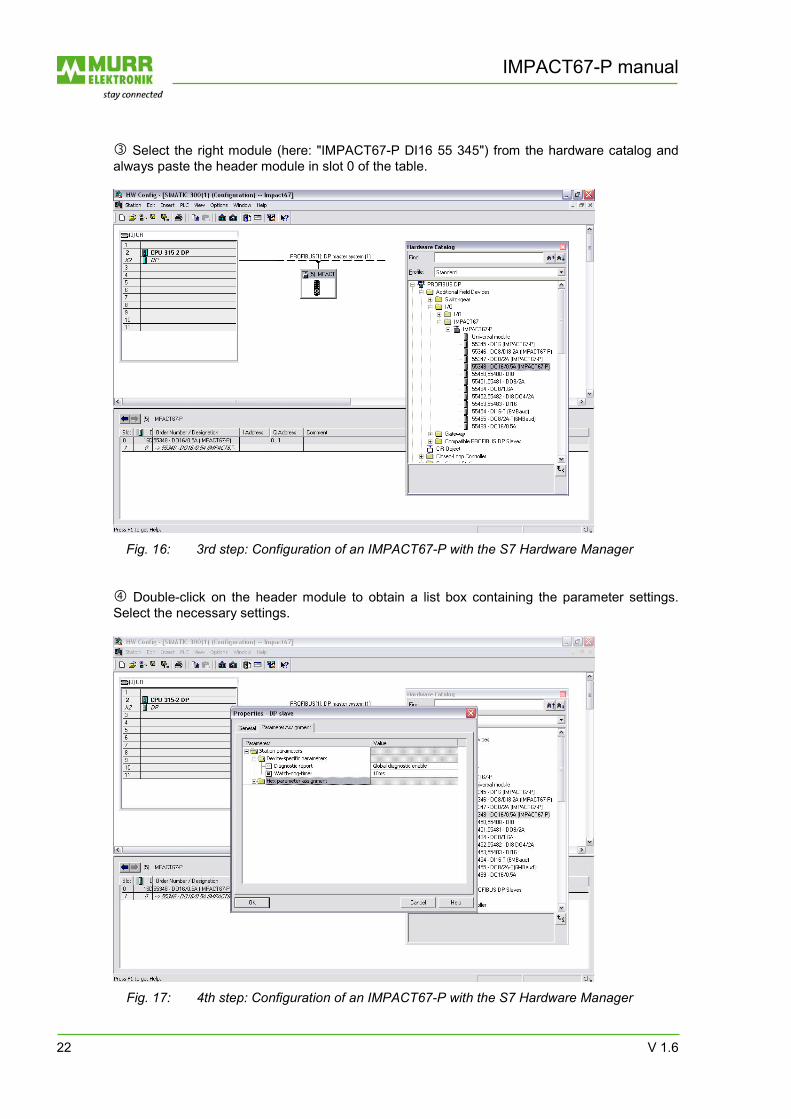
Select the right module (here: "IMPACT67-P DI16 55 345") from the hardware catalog and always paste the header module in slot 0 of the table.
Fig. 16: 3rd step: Configuration of an IMPACT67-P with the S7 Hardware Manager
Double-click on the header module to obtain a list box containing the parameter settings. Select the necessary settings.
Fig. 17: 4th step: Configuration of an IMPACT67-P with the S7 Hardware Manager
V 1.6 23
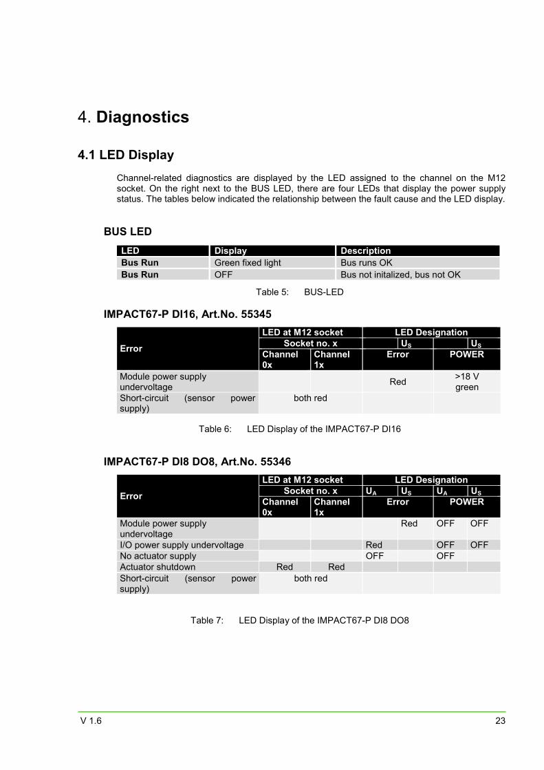
4. Diagnostics 4.1 LED Display
Channel-related diagnostics are displayed by the LED assigned to the channel on the M12 socket. On the right next to the BUS LED, there are four LEDs that display the power supply status. The tables below indicated the relationship between the fault cause and the LED display.
BUS LED
LED Display Description Bus Run Green fixed light Bus runs OK Bus Run OFF Bus not initalized, bus not OK
Table 5: BUS-LED
IMPACT67-P DI16, Art.No. 55345
Error
LED at M12 socket LED DesignationSocket no. x US US
Channel 0x
Channel 1x
Error POWER
Table 6: LED Display of the IMPACT67-P DI16
IMPACT67-P DI8 DO8, Art.No. 55346
Error
LED at M12 socket LED DesignationSocket no. x UA US UA US
Channel 0x
Channel 1x
Error POWER
Module power supply undervoltage
Red OFF OFF
I/O power supply undervoltage Red OFF OFF No actuator supply OFF OFF Actuator shutdown Red Red
Table 7: LED Display of the IMPACT67-P DI8 DO8
Module power supply undervoltage
Red >18 V green
Short-circuit (sensor power supply)
both red
Short-circuit (sensor power supply)
both red
IMPACT67-P manual
24 V 1.6
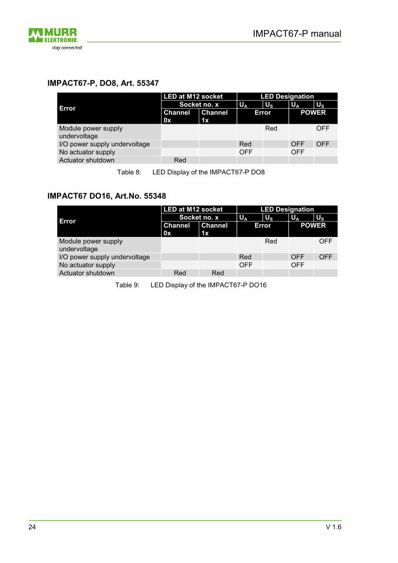
IMPACT67-P, DO8, Art. 55347
Error
LED at M12 socket LED Designation Socket no. x UA US UA US
Channel 0x
Channel 1x
Error POWER
Module power supply undervoltage
Red OFF
I/O power supply undervoltage Red OFF OFF No actuator supply OFF OFF Actuator shutdown Red
Table 8: LED Display of the IMPACT67-P DO8
IMPACT67 DO16, Art.No. 55348
Error
LED at M12 socket LED Designation Socket no. x UA US UA US
Channel 0x
Channel 1x
Error POWER
Module power supply undervoltage
Red OFF
I/O power supply undervoltage Red OFF OFF No actuator supply OFF OFF Actuator shutdown Red Red
Table 9: LED Display of the IMPACT67-P DO16
V 1.6 25
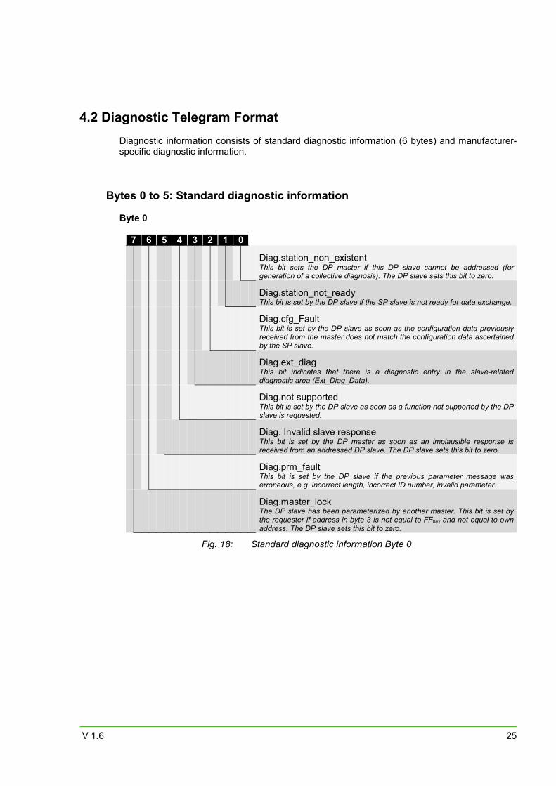
4.2 Diagnostic Telegram Format
Diagnostic information consists of standard diagnostic information (6 bytes) and manufacturer-specific diagnostic information.
Bytes 0 to 5: Standard diagnostic information Byte 0
7 6 5 4 3 2 1 0
Diag.station_non_existent This bit sets the DP master if this DP slave cannot be addressed (for generation of a collective diagnosis). The DP slave sets this bit to zero.
Diag.station_not_ready This bit is set by the DP slave if the SP slave is not ready for data exchange.
Diag.cfg_Fault This bit is set by the DP slave as soon as the configuration data previously received from the master does not match the configuration data ascertained by the SP slave.
Diag.ext_diag This bit indicates that there is a diagnostic entry in the slave-related diagnostic area (Ext_Diag_Data).
Diag.not supported This bit is set by the DP slave as soon as a function not supported by the DP slave is requested.
Diag. Invalid slave response This bit is set by the DP master as soon as an implausible response is received from an addressed DP slave. The DP slave sets this bit to zero.
Diag.prm_fault This bit is set by the DP slave if the previous parameter message was erroneous, e.g. incorrect length, incorrect ID number, invalid parameter.
Diag.master_lock The DP slave has been parameterized by another master. This bit is set by the requester if address in byte 3 is not equal to FFhex and not equal to own address. The DP slave sets this bit to zero.
Fig. 18: Standard diagnostic information Byte 0
IMPACT67-P manual
26 V 1.6
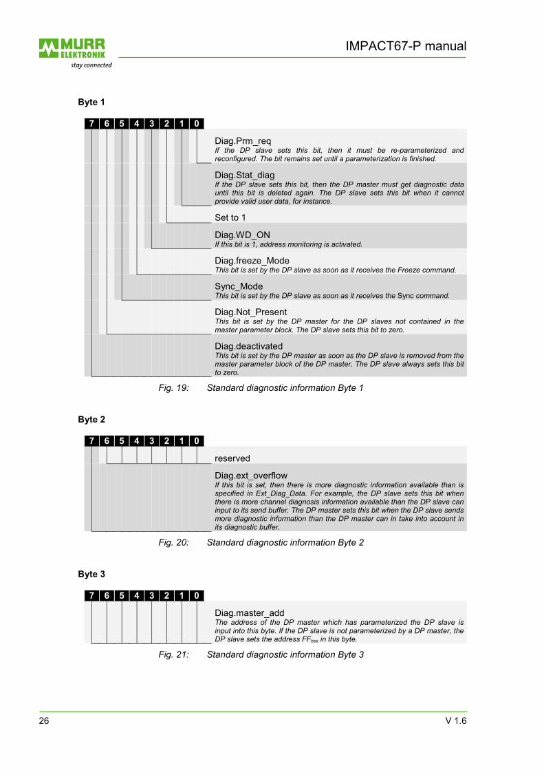
Byte 1
7 6 5 4 3 2 1 0
Diag.Prm_req If the DP slave sets this bit, then it must be re-parameterized and reconfigured. The bit remains set until a parameterization is finished.
Diag.Stat_diag If the DP slave sets this bit, then the DP master must get diagnostic data until this bit is deleted again. The DP slave sets this bit when it cannot provide valid user data, for instance.
Set to 1
Diag.WD_ON If this bit is 1, address monitoring is activated.
Diag.freeze_Mode This bit is set by the DP slave as soon as it receives the Freeze command.
Sync_Mode This bit is set by the DP slave as soon as it receives the Sync command.
Diag.Not_Present This bit is set by the DP master for the DP slaves not contained in the master parameter block. The DP slave sets this bit to zero.
Diag.deactivated This bit is set by the DP master as soon as the DP slave is removed from the master parameter block of the DP master. The DP slave always sets this bit to zero.
Fig. 19: Standard diagnostic information Byte 1 Byte 2
7 6 5 4 3 2 1 0
reserved
Diag.ext_overflow If this bit is set, then there is more diagnostic information available than is specified in Ext_Diag_Data. For example, the DP slave sets this bit when there is more channel diagnosis information available than the DP slave can input to its send buffer. The DP master sets this bit when the DP slave sends more diagnostic information than the DP master can in take into account in its diagnostic buffer.
Fig. 20: Standard diagnostic information Byte 2 Byte 3
7 6 5 4 3 2 1 0
Diag.master_add The address of the DP master which has parameterized the DP slave is input into this byte. If the DP slave is not parameterized by a DP master, the DP slave sets the address FFhex in this byte.
Fig. 21: Standard diagnostic information Byte 3
V 1.6 27
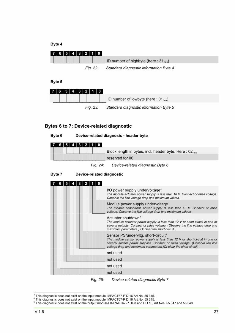
Byte 4 7 6 5 4 3 2 1 0
ID number of highbyte (here : 31hex)
Fig. 22: Standard diagnostic information Byte 4 Byte 5 7 6 5 4 3 2 1 0
ID number of lowbyte (here : 01hex)
Fig. 23: Standard diagnostic information Byte 5
Bytes 6 to 7: Device-related diagnostic Byte 6 Device-related diagnosis - header byte 7 6 5 4 3 2 1 0
Block length in bytes, incl. header byte. Here : 02hex
reserved for 00
Fig. 24: Device-related diagnostic Byte 6 Byte 7 Device-related diagnostic 7 6 5 4 3 2 1 0
I/O power supply undervoltage3 The module actuator power supply is less than 18 V. Connect or raise voltage. Observe the line voltage drop and maximum values.
Module power supply undervoltage
The module sensor/bus power supply is less than 18 V. Connect or raise voltage. Observe the line voltage drop and maximum values.
Actuator shutdown4 The module actuator power supply is less than 12 V or short-circuit in one or several outputs. Connect or raise voltage. (Observe the line voltage drop and maximum parameters.) Or clear the short-circuit.
Sensor PS/undervltg. short-circuit5 The module sensor power supply is less than 12 V or short-circuit in one or several sensor power supplies. Connect or raise voltage. (Observe the line voltage drop and maximum parameters.)Or clear the short-circuit.
not used
not used
not used
not used
Fig. 25: Device-related diagnostic Byte 7
3 This diagnostic does not exist on the input module IMPACT67-P DI16 Art.No. 55 345. 4 This diagnostic does not exist on the input module IMPACT67-P DI16 Art.No. 55 345. 5 This diagnostic does not exist on the output modules IMPACT67-P DO8 and DO 16, Art.Nos. 55 347 and 55 348.
IMPACT67-P manual
28 V 1.6
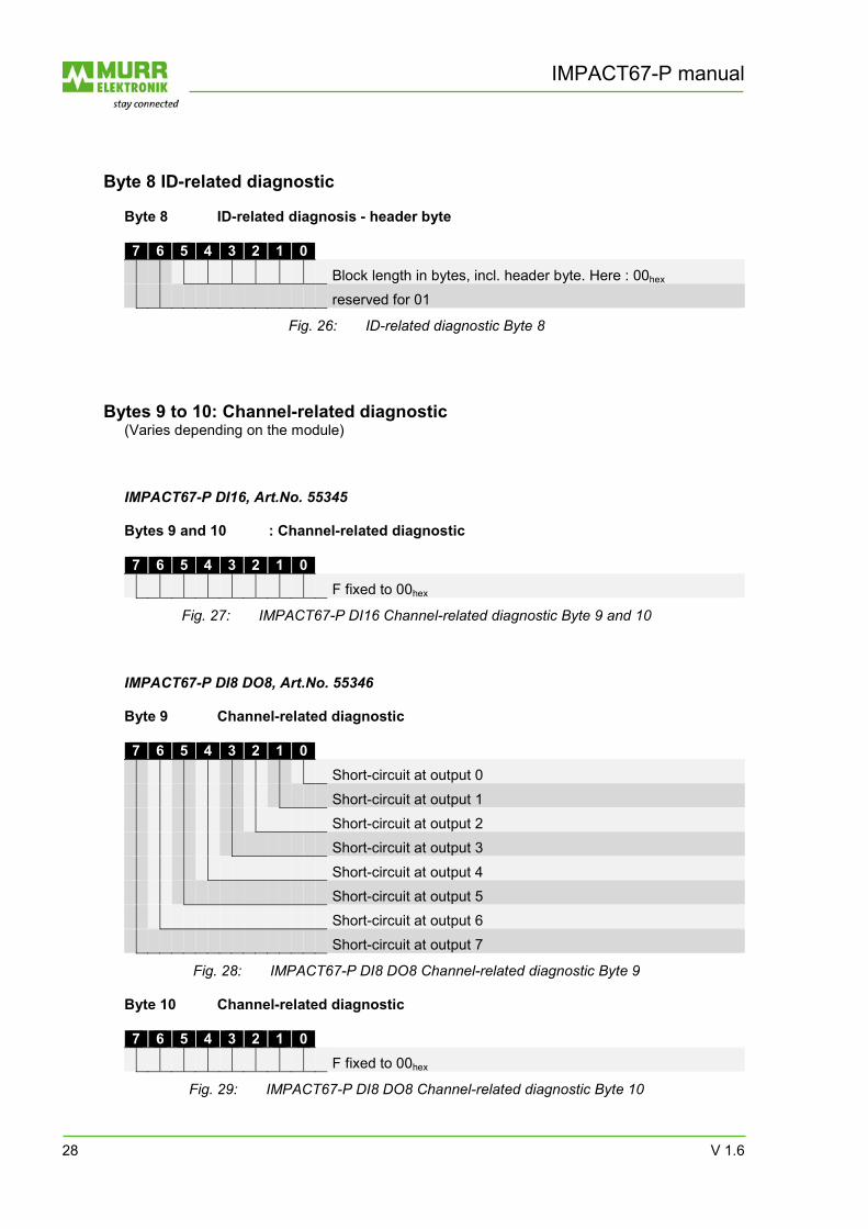
Byte 8 ID-related diagnostic
Byte 8 ID-related diagnosis - header byte 7 6 5 4 3 2 1 0
Block length in bytes, incl. header byte. Here : 00hex
reserved for 01
Fig. 26: ID-related diagnostic Byte 8
Bytes 9 to 10: Channel-related diagnostic (Varies depending on the module) IMPACT67-P DI16, Art.No. 55345 Bytes 9 and 10 : Channel-related diagnostic 7 6 5 4 3 2 1 0
F fixed to 00hex
Fig. 27: IMPACT67-P DI16 Channel-related diagnostic Byte 9 and 10 IMPACT67-P DI8 DO8, Art.No. 55346 Byte 9 Channel-related diagnostic 7 6 5 4 3 2 1 0
Short-circuit at output 0
Short-circuit at output 1
Short-circuit at output 2
Short-circuit at output 3
Short-circuit at output 4
Short-circuit at output 5
Short-circuit at output 6
Short-circuit at output 7
Fig. 28: IMPACT67-P DI8 DO8 Channel-related diagnostic Byte 9 Byte 10 Channel-related diagnostic 7 6 5 4 3 2 1 0
F fixed to 00hex
Fig. 29: IMPACT67-P DI8 DO8 Channel-related diagnostic Byte 10
V 1.6 29
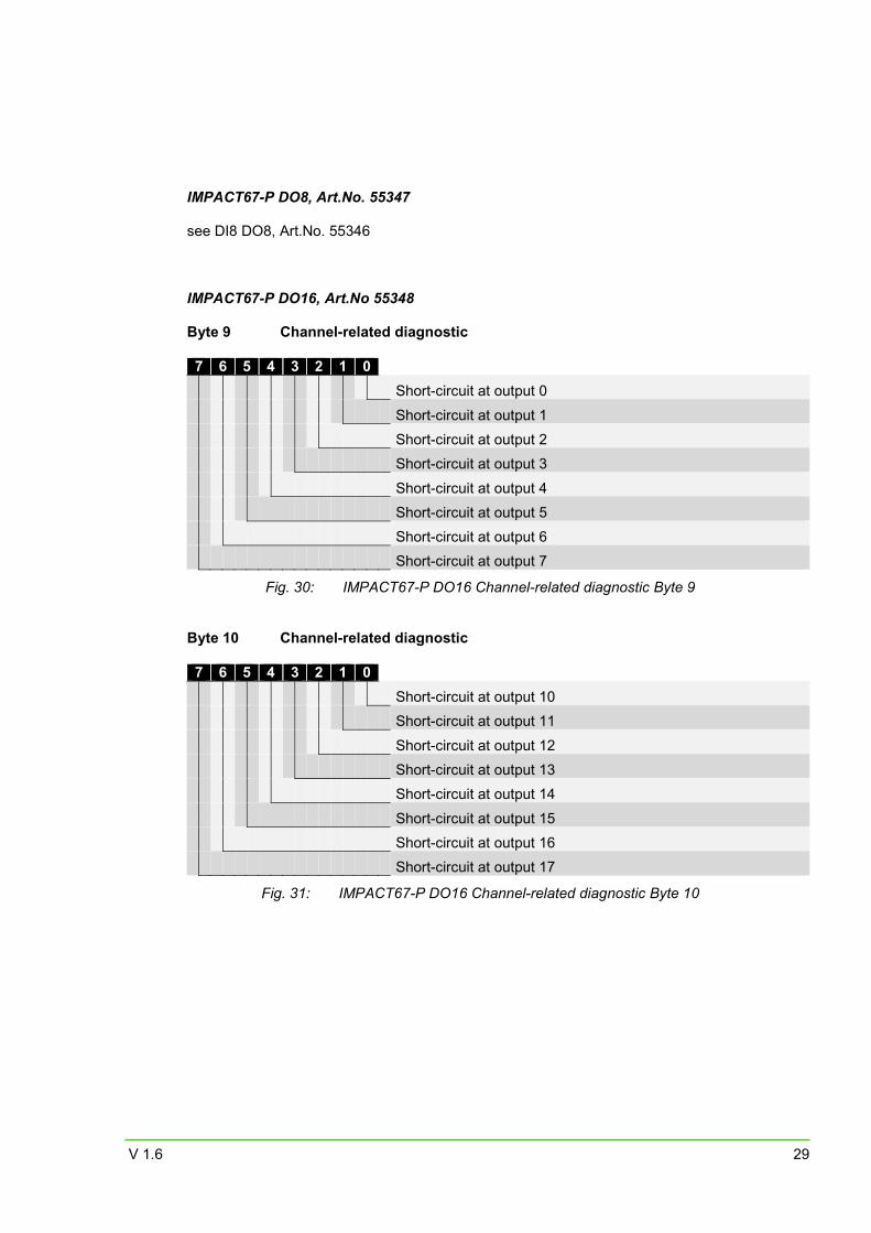
IMPACT67-P DO8, Art.No. 55347 see DI8 DO8, Art.No. 55346
IMPACT67-P DO16, Art.No 55348 Byte 9 Channel-related diagnostic 7 6 5 4 3 2 1 0
Short-circuit at output 0
Short-circuit at output 1
Short-circuit at output 2
Short-circuit at output 3
Short-circuit at output 4
Short-circuit at output 5
Short-circuit at output 6
Short-circuit at output 7
Fig. 30: IMPACT67-P DO16 Channel-related diagnostic Byte 9 Byte 10 Channel-related diagnostic 7 6 5 4 3 2 1 0
Short-circuit at output 10
Short-circuit at output 11
Short-circuit at output 12
Short-circuit at output 13
Short-circuit at output 14
Short-circuit at output 15
Short-circuit at output 16
Short-circuit at output 17
Fig. 31: IMPACT67-P DO16 Channel-related diagnostic Byte 10
IMPACT67-P manual
30 V 1.6
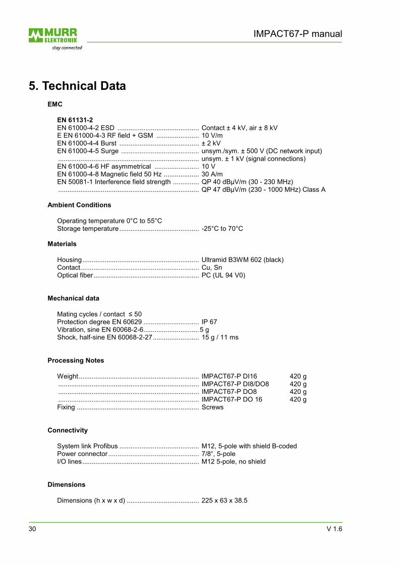
5. Technical Data
EMC
EN 61131-2 EN 61000-4-2 ESD ............................................ Contact ± 4 kV, air ± 8 kV E EN 61000-4-3 RF field + GSM ....................... 10 V/m EN 61000-4-4 Burst ........................................... ± 2 kV EN 61000-4-5 Surge .......................................... unsym./sym. ± 500 V (DC network input) ............................................................................ unsym. ± 1 kV (signal connections) EN 61000-4-6 HF asymmetrical ........................ 10 V EN 61000-4-8 Magnetic field 50 Hz ................... 30 A/m EN 50081-1 Interference field strength .............. QP 40 dBµV/m (30 - 230 MHz) ............................................................................ QP 47 dBµV/m (230 - 1000 MHz) Class A
Ambient Conditions
Operating temperature 0°C to 55°C Storage temperature ........................................... -25°C to 70°C
Materials
Housing ............................................................... Ultramid B3WM 602 (black) Contact ................................................................ Cu, Sn Optical fiber ......................................................... PC (UL 94 V0)
Mechanical data
Mating cycles / contact ≤ 50 Protection degree EN 60629 .............................. IP 67 Vibration, sine EN 60068-2-6 .............................. 5 g Shock, half-sine EN 60068-2-27 ......................... 15 g / 11 ms
Processing Notes
Weight ................................................................. IMPACT67-P DI16 420 g ............................................................................ IMPACT67-P DI8/DO8 420 g ............................................................................ IMPACT67-P DO8 420 g ............................................................................ IMPACT67-P DO 16 420 g Fixing .................................................................. Screws
Connectivity
System link Profibus ........................................... M12, 5-pole with shield B-coded Power connector ................................................. 7/8“, 5-pole I/O lines ............................................................... M12 5-pole, no shield
Dimensions
Dimensions (h x w x d) ....................................... 225 x 63 x 38.5
V 1.6 31
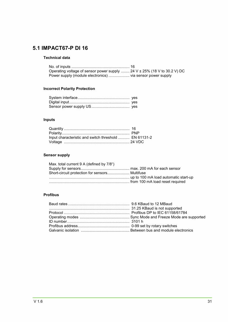
5.1 IMPACT67-P DI 16
Technical data
No. of inputs ....................................................... 16 Operating voltage of sensor power supply ........ 24 V ± 25% (18 V to 30.2 V) DC Power supply (module electronics) .................... via sensor power supply
Incorrect Polarity Protection
System interface ................................................. yes Digital input ......................................................... yes Sensor power supply US .................................... yes
Inputs
Quantity .............................................................. 16 Polarity ................................................................ PNP Input characteristic and switch threshold ........... EN 61131-2 Voltage .............................................................. 24 VDC
Sensor supply
Max. total current 9 A (defined by 7/8“) Supply for sensors .............................................. max. 200 mA for each sensor Short-circuit protection for sensors..................... Multifuse ............................................................................ up to 100 mA load automatic start-up ............................................................................ from 100 mA load reset required
Profibus
Baud rates .......................................................... 9.6 KBaud to 12 MBaud ............................................................................ 31.25 KBaud is not supported Protocol .............................................................. Profibus DP to IEC 61158/61784 Operating modes ............................................... Sync Mode and Freeze Mode are supported ID number ........................................................... 3101 h Profibus address................................................. 0-99 set by rotary switches Galvanic isolation .............................................. Between bus and module electronics
IMPACT67-P manual
32 V 1.6
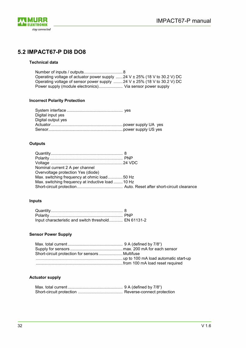
5.2 IMPACT67-P DI8 DO8
Technical data
Number of inputs / outputs .................................. 8 Operating voltage of actuator power supply ...... 24 V ± 25% (18 V to 30.2 V) DC Operating voltage of sensor power supply ........ 24 V ± 25% (18 V to 30.2 V) DC Power supply (module electronics) ..................... Via sensor power supply
Incorrect Polarity Protection
System interface ................................................. yes Digital input yes Digital output yes Actuator ............................................................... power supply UA yes Sensor ................................................................. power supply US yes
Outputs
Quantity ............................................................... 8 Polarity ................................................................ PNP Voltage ............................................................... 24 VDC Nominal current 2 A per channel Overvoltage protection Yes (diode) Max. switching frequency at ohmic load ............. 50 Hz Max. switching frequency at inductive load ........ 10 Hz Short-circuit protection ........................................ Auto. Reset after short-circuit clearance
Inputs
Quantity ............................................................... 8 Polarity ................................................................ PNP Input characteristic and switch threshold ............ EN 61131-2
Sensor Power Supply
Max. total current ................................................ 9 A (defined by 7/8“) Supply for sensors .............................................. max. 200 mA for each sensor Short-circuit protection for sensors ..................... Multifuse ............................................................................ up to 100 mA load automatic start-up ............................................................................ from 100 mA load reset required
Actuator supply
Max. total current ................................................ 9 A (defined by 7/8“) Short-circuit protection ....................................... Reverse-connect protection
V 1.6 33
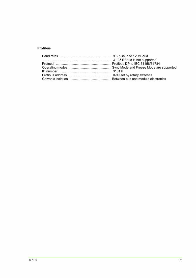
Profibus
Baud rates .......................................................... 9.6 KBaud to 12 MBaud ............................................................................ 31.25 KBaud is not supported Protocol ............................................................. Profibus DP to IEC 61158/61784 Operating modes ............................................... Sync Mode and Freeze Mode are supported ID number ........................................................... 3101 h Profibus address................................................. 0-99 set by rotary switches Galvanic isolation .............................................. Between bus and module electronics
IMPACT67-P manual
34 V 1.6
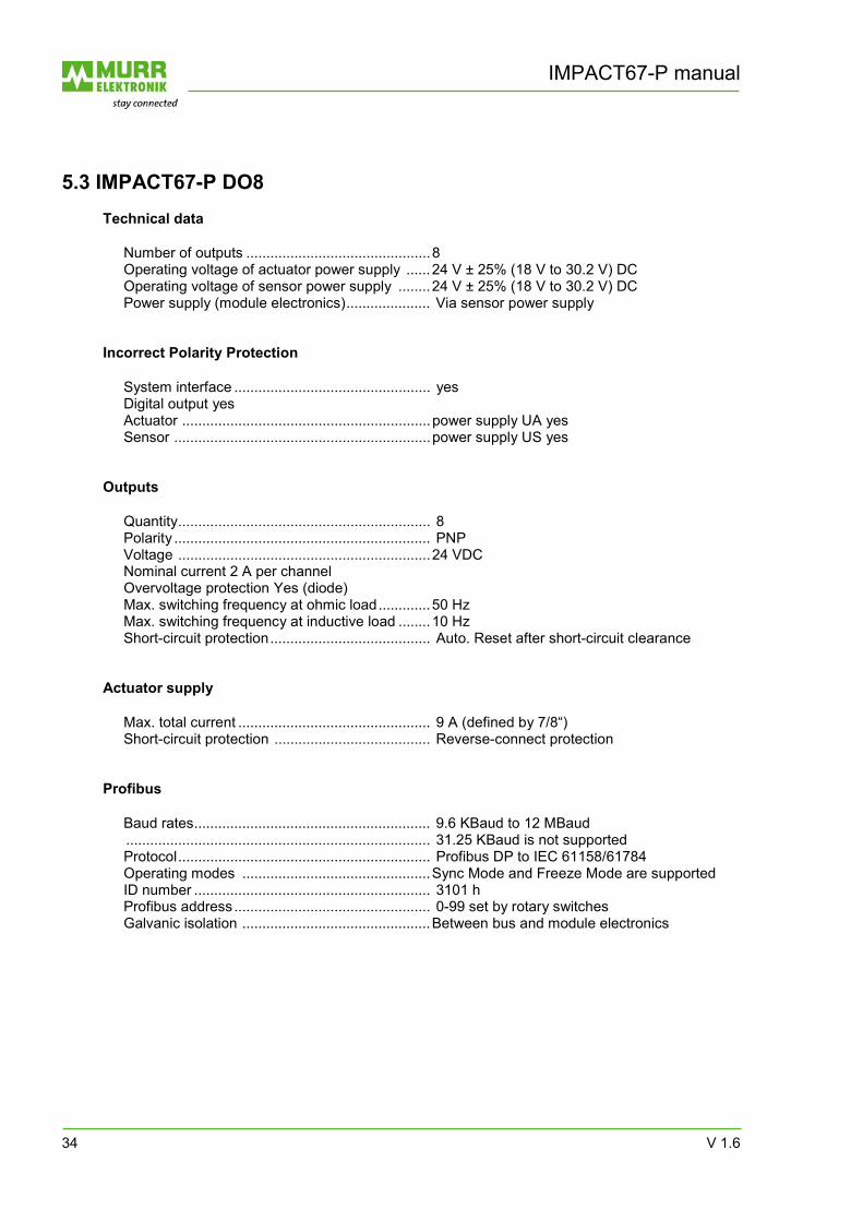
5.3 IMPACT67-P DO8
Technical data
Number of outputs .............................................. 8 Operating voltage of actuator power supply ...... 24 V ± 25% (18 V to 30.2 V) DC Operating voltage of sensor power supply ........ 24 V ± 25% (18 V to 30.2 V) DC Power supply (module electronics) ..................... Via sensor power supply
Incorrect Polarity Protection
System interface ................................................. yes Digital output yes Actuator .............................................................. power supply UA yes Sensor ................................................................ power supply US yes
Outputs
Quantity ............................................................... 8 Polarity ................................................................ PNP Voltage ............................................................... 24 VDC Nominal current 2 A per channel Overvoltage protection Yes (diode) Max. switching frequency at ohmic load ............. 50 Hz Max. switching frequency at inductive load ........ 10 Hz Short-circuit protection ........................................ Auto. Reset after short-circuit clearance
Actuator supply
Max. total current ................................................ 9 A (defined by 7/8“) Short-circuit protection ....................................... Reverse-connect protection
Profibus
Baud rates ........................................................... 9.6 KBaud to 12 MBaud ............................................................................ 31.25 KBaud is not supported Protocol ............................................................... Profibus DP to IEC 61158/61784 Operating modes ............................................... Sync Mode and Freeze Mode are supported ID number ........................................................... 3101 h Profibus address ................................................. 0-99 set by rotary switches Galvanic isolation ............................................... Between bus and module electronics
V 1.6 35
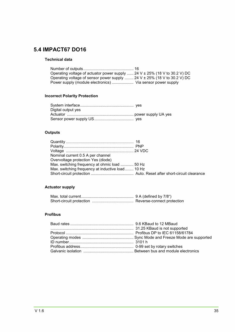
5.4 IMPACT67 DO16
Technical data
Number of outputs .............................................. 16 Operating voltage of actuator power supply ...... 24 V ± 25% (18 V to 30.2 V) DC Operating voltage of sensor power supply ........ 24 V ± 25% (18 V to 30.2 V) DC Power supply (module electronics) .................... Via sensor power supply
Incorrect Polarity Protection
System interface ................................................. yes Digital output yes Actuator ............................................................. power supply UA yes Sensor power supply US .................................... yes
Outputs
Quantity .............................................................. 16 Polarity ................................................................ PNP Voltage .............................................................. 24 VDC Nominal current 0.5 A per channel Overvoltage protection Yes (diode) Max. switching frequency at ohmic load ............ 50 Hz Max. switching frequency at inductive load ........ 10 Hz Short-circuit protection ....................................... Auto. Reset after short-circuit clearance
Actuator supply
Max. total current ................................................ 9 A (defined by 7/8“) Short-circuit protection ...................................... Reverse-connect protection
Profibus
Baud rates .......................................................... 9.6 KBaud to 12 MBaud ............................................................................ 31.25 KBaud is not supported Protocol .............................................................. Profibus DP to IEC 61158/61784 Operating modes ............................................... Sync Mode and Freeze Mode are supported ID number ........................................................... 3101 h Profibus address................................................. 0-99 set by rotary switches Galvanic isolation .............................................. Between bus and module electronics
IMPACT67-P manual
36 V 1.6
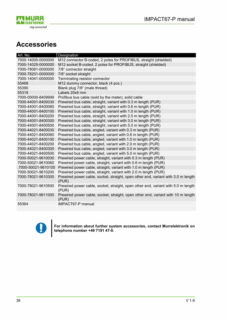
Accessories Art. No. Designation 7000-14005-0000000 M12 connector B-coded, 2 poles for PROFIBUS, straight (shielded) 7000-14025-0000000 M12 socket B-coded, 2 poles for PROFIBUS, straight (shielded) 7000-78081-0000000 7/8“ connector straight 7000-78201-0000000 7/8“ socket straight 7000-14041-0000000 Terminating resistor connector 55468 M12 dummy connector, black (4 pcs.) 55390 Blank plug 7/8“ (male thread) 55318 Labels 20x8 mm 7000-00000-8409999 Profibus bus cable (sold by the meter), solid cable 7000-44001-8400030 Prewired bus cable, straight, variant with 0.3 m length (PUR) 7000-44001-8400060 Prewired bus cable, straight, variant with 0.6 m length (PUR) 7000-44001-8400100 Prewired bus cable, straight, variant with 1.0 m length (PUR) 7000-44001-8400200 Prewired bus cable, straight, variant with 2.0 m length (PUR) 7000-44001-8400300 Prewired bus cable, straight, variant with 3.0 m length (PUR) 7000-44001-8400500 Prewired bus cable, straight, variant with 5.0 m length (PUR) 7000-44021-8400030 Prewired bus cable, angled, variant with 0.3 m length (PUR) 7000-44021-8400060 Prewired bus cable, angled, variant with 0.6 m length (PUR) 7000-44021-8400100 Prewired bus cable, angled, variant with 1.0 m length (PUR) 7000-44021-8400200 Prewired bus cable, angled, variant with 2.0 m length (PUR) 7000-44021-8400300 Prewired bus cable, angled, variant with 3.0 m length (PUR) 7000-44021-8400500 Prewired bus cable, angled, variant with 5.0 m length (PUR) 7000-50021-9610030 Prewired power cable, straight, variant with 0.3 m length (PUR) 7000-50021-9610060 Prewired power cable, straight, variant with 0.6 m length (PUR) .7000-50021-9610100 Prewired power cable, straight, variant with 1.0 m length (PUR) 7000-50021-9610200 Prewired power cable, straight, variant with 2.0 m length (PUR) 7000-78021-9610300 Prewired power cable, socket, straight, open other end, variant with 3.0 m length
(PUR) 7000-78021-9610500 Prewired power cable, socket, straight, open other end, variant with 5.0 m length
(PUR) 7000-78021-9611000 Prewired power cable, socket, straight, open other end, variant with 10 m length
(PUR) 55364 IMPACT67-P manual
For information about further system accessories, contact Murrelektronik on telephone number +49 7191 47-0.

V 1.6 37
Glossary
General Information About Profibus
Bus segment The electrical specification of the RS-485 interface limits the number of users on an RS485 network to 32. If there are more than 32 Profibus users, divide the network into segments using repeaters.
DP Decentral Periphery, Profibus protocol for rapid cyclical data exchange. Freeze mode The Input data of the slave are "frozen". GAP factor The number of bus passes after which a DP Master searches for
additional active users to include them in the token ring. This factor can be modified to optimize the speed of a DP network.
GAP area The address area in which an active user searches for additional active
users. This area is always between the own address and the address of the next active user already in the Token Ring. The area from the highest address up to 127 does not belong to the GAP area.
GSD The devices master file describes the technical features of a Profibus
product. This file is required to configure a Profibus system, and is provided by the device's manufacturer.
ID number A 16-bit number which clearly identifies a Profibus product. It is a
reference to the GSD file. Other devices may have the same ID number, provided they can be configured in a common GSD file. This number is allocated by Profibus Nutzerorganisation e.V..
IEC 61158 Globally recognized standard for Profibus DP and FMS Successor of the
international standard EN 50170, Volume 2. Byte Term defined by IEC 61158. 1 byte corresponds to 8 bits. PNO Profibus Nutzerorganisation e.V (German Profibus user organization). Repeater Coupling element for signal conditioning between Profibus segments. SPC Stored Program Controller Sync Mode The output data of the Slave are "frozen". Token The active user (master) in possession of the token can carry out data
exchange with the slaves which it has parameterized and configured. On completion of the data cycle, the active user passes the token on to the next active user.
IMPACT67-P manual
38 V 1.6
IMPACT67-P specific
Sensor short-circuit Short circuit or overload at Pin 1 of the M12 socket causes the self-resetting fuse to trip. Each M12 socket is separately fused. A red LED indicates the fault at the associated M12 socket. This error is signaled via the DP diagnostics. The sensor power supply is automatically reset after the fault is rectified.
Actuator shutdown Short-circuit or overload at an output causes the output to be disabled.
This error is signaled via the DP diagnostics. A red LED indicates the fault at the associated M12 socket. This is followed by an automatic restart of the output.
Undervoltage The voltages of the sensor power supply and actuator power supply are
detected separately. If 18 VDC is undershot, this error is signaled via the DP diagnostics. If the sensor power supply suffers from undervoltage, the LED labeled "US Error" lights up red. If the actuator power supply suffers from undervoltage, the LED labeled "UA Error" lights up red.
V 1.6 39
Legal Provisions
Exclusion of Liability
Murrelektronik GmbH has checked the contents of this technical documentation for conformity with the hardware and software described therein. Deviations can not be excluded in individual cases. For this reason, Murrelektronik excludes the warranty for the correctness of its contents and any liability for errors, in particular full conformity. The limitation of liability shall not apply if the cause for damage is attributable to willful intent and/or gross negligence, or for all claims arising from the Product Liability Law. Should a major contractual obligation be violated by criminal negligence, the liability of Murrelektronik GmbH shall be limited to damages that typically arise. Subject to technical changes and alternations in content. We advise that you check at regular intervals whether this documentation has been updated since corrections that may become necessary due to technical advances are included by Murrelektronik GmbH at regular intervals. We are gratefully for any suggestions for improvement. Copyright
It is prohibited to transfer or photocopy the documentation either in paper or in digital form, reuse or divulge its contents unless otherwise expressly permitted by Murrelektronik GmbH or in conjunction with the production of documentation for third-party products that contain products made by Murrelektronik GmbH. Violations will result in liability for damages. All rights reserved, in particular in the event of the award of patents or granting of utility models. Right of Use
Murrelektronik GmbH grants its customers a non-exclusive right revocable at any time and for an indefinite period of time to use this documentation to produce their own technical documentation. For this purpose, the documentation produced by Murrelektronik GmbH may be changed in parts, or amended, or copied ,and transferred to the customer's users as part of the customer's own technical documentation on paper or on electronic media. The customer shall then bear sole responsibility for the correctness of the contents of the technical documentation produced by him. If the technical documentation is integrated in part, or in full in the customer's technical documentation, the customer shall refer to the copyright of Murrelektronik GmbH. Furthermore, special attention shall be paid to compliance with the safety instructions. Although the customer is obliged to make reference to the copyright of Murrelektronik GmbH, provided the technical documentation of Murrelektronik GmbH is used, the customer shall market and/or use the technical documentation on his sole responsibility. The reason is that Murrelektronik GmbH has no influence on changes or applications of the technical documentation and even minor changes to the starting product or deviations in the intended applications may render incorrect the specifications contained in the technical documentation. For this reason, the customer is obliged to identify the technical documentation originating from Murrelektronik GmbH if and inasmuch as the documentation is changed by the customer. The customer shall be obliged to release Murrelektronik from the damage claims of third parties if the latter are attributable to any deficits in the documentation. This shall not apply to damages to the rights of third parties caused by deliberate or criminal intent. The customer shall be entitled to use the company brands of Murrelektronik GmbH exclusively for his product advertising, but only inasmuch as the products of Murrelektronik GmbH are integrated in the products marketed by the customer. The customer shall refer to the brands of Murrelektronik GmbH in an adequate manner if the brands of Murrelektronik GmbH were used.

Murrelektronik GmbH|Falkenstraße 3, D-71570 Oppenweiler|P.O. Box 1165, D-71567 Oppenweiler
Phone +49 7191 47-0|Fax +49 7191 47-130|[email protected]|www.murrelektronik.com
The information in this manual has been compiled with the utmost care. Liability for the correctness, completeness and topicality
of the information is restricted to gross negligence.