instruction manual for precision surface grinder … · kgs818ah/ahd . 1.5kw : 90w . 1.5kw : 550w ....
TRANSCRIPT
INSTRUCTION MANUAL FOR
PRECISION SURFACE GRINDER
MODEL:KGS818AH
KGS1020AHD
KENT INDUSTRIAL (U.S.A.) INC Prop
erty o
f Ken
t Indu
strial
USA
Please
Do N
ot Rep
roduc
e

2
Chapter One Installation Guidelines
General Safety Rules
Do 1. The employer must select trained and qualified personnel to operate machinery.2. The employer must adhere to local national safety laws and regulations when
teaching operators safety and cleanly procedures.3. The employer must inform operators to look out for unsafe operating practices.4. The brightness of the lighting equipment in the workplace must conform to local
government regulations.5. The machine's fire extinguisher must use non-conducting CO_2 or ABC.6. The operation manual, instructions, and warning labels must be read before
operating the machine.7. The operation manual must be kept ready at all times. If an accident occurs, please
contact our company representatives.8. Hair must be properly restrained. Wear a hat if necessary before operating or
maintaining the machine.9. Before operating the machine, safety glasses, a filter mask, and work safety shoes
must be worn.10. The machine and its surrounding area must be kept clean and orderly to prevent
slippery surfaces and unnecessary obstacles.11. The operator must remain at least 600 mm away from the machine to prevent
contact with the machine and injury. A yellow line should be drawn to mark areaswhere personnel are restricted from entering.
12. Operation and maintenance personnel must only work within the designated safeareas.
13. When moving work pieces that exceed 30 kilograms, use a hoist operated bylicensed personnel to lift and lower these pieces.
14. All protective guards and doors must be closed at all times, except whenmaintenance work is being done.
15. Before conducting any maintenance work, the power source should be turned offand only proper tools should be used.
Don't 1. Persons wearing ties, long sleeves, or loose fitting clothing should not operate or
maintain the machine.2. Persons within the work area must not lean on the machine while it is running.3. When the machine is running, the wheel guard, right and left storke adjusters, and
nozzles must not be adjusted by hand or with tools.4. To prevent eye injury to personnel by dust particles, compressed air should not be
used to clean the machine.
1.1 Safety rules for this machinery
Propert
y of K
ent In
dustr
ial U
SA
Please
Do N
ot Rep
roduc
e

3
Do 1. Only use grinding wheel with a maximum peripheral speed of 2000 m/min or
greater.2. Before inspecting or maintaining the power source, make sure you are following the
instructions that are given on the warning signs.3. If warning or instruction signs should fall off the machine or become illegible, re-
affix with replacement signs or contact your sales representative or this companyfor replacements.
4. When inspecting electrical sections of the machine, insulating gloves, rubber orleather boots, and other non-conducting protective items should be used.
5. Electrical wiring that needs to be grounded, must be done so following the diagramsprovided.
6. Before inspecting electrical circuits, check to make sure that the circuit is turnedoff.
7. When the electrical portions malfunction, only qualified personnel should carry ourthe maintenance work.
8. Check with the grinding wheel manufacturer about grinding wheel specificationsfor work pieces with a hardness of HRC65.
9. The grinding wheel balancing should be done by trained personnel only. Afterbalancing the grinding wheel, it can be mounted onto the wheel spindle. Beforemounting, wipe the flange and the mounting portion of the wheel spindle clean.
10. Before starting the machine, find the location of the machine stop and emergencypush-buttons.
11. Before starting up the wheel spindle motor, inspect the grinding wheel and theturning direction of the wheel spindle. After starting the wheel spindle motor, let thegrinding wheel spin freely for at least five minutes before beginning to grind thework piece.
12. Make sure the surface of the electric magnet chuck is clean before mounting workpieces. If there are marks on the surface, regrind its surface.
13. Use the proper clamps when mounting non-magnetic material work pieces such asaluminum, graphite, etc., or work pieces that are difficult to hold onto the magneticchuck. These clamps cannot come into contact with the grinding wheel.
14. When the grinding wheel is not turning, the operator should check with his hands tosee whether the work piece is firmly attached to the magnetic plate.
15. Adjust the left or right stroke only when the table is at a stop.16. For wet grinding, turn off the coolant system before turning off the spindle motor.17. Wet grinding material that produce dust during the grinding process.
Don't 1. The machine must not be installed in areas with explosive materials.2. Combustible liquids must not be used as a cutting liquid.3. The machine should not be used to grind lumber, plastic, or other combustible
materials. Please contact KENT Industrial Co, Ltd. if you wish to use optional orspecial equipment provided by the company to grind graphite or porcelain.
4. The grinding wheel on the wheel spindle head cannot be used as a disk sander.5. Do not haphazardly change the use and/or capacity setting on the machine and do
Propert
y of K
ent In
dustr
ial U
SA
Please
Do N
ot Rep
roduc
e

4
not use grinding wheels that do not conform to listed specifications or work pieces that are excessively large or heavy.
6. To avoid the risk of an accident, the user should not modify the electrical circuitrywithout prior authorization.
7. Do not change interlocking circuits into bypass circuits.8. Do not come into contact with those areas of the machine that are labeled with
lightning signs and decals.9. Do not come into contact with the electrical box or circuits when one's body or
hands are wet.10. When inspecting or maintaining electrical sections, keep all personal metallic items
away from possible contact. Additionally, hang a warning sign to prevent otherpersonnel from inadvertently starting the machine.
11. Do not use very thin and short work pieces, or work pieces which have complexshapes or unstable centers of gravity on the magnetic chuck for grinding.
12. When grinding, make sure the work piece is securely mounted and that no otherobject is place on the machine.
13. During wet grinding, the nozzles cannot be adjusted when the wheel spindle isrotating.
14. When the work table is in motion or when the wheel spindle is rotating, the workpiece cannot be moved or changed.
15. After the wheel spindle motor is turned off, do not use your hand or any otherobject to stop or slow down the grinding wheel.
16. During grinding and before the grinding wheel stops rotating after work is finished,do not attempt to clean the shavings of the work piece or move the work piece.
17. When taking off the grinding wheel, use a flange remover to detach it. Do not useany method that involves pounding the grinding wheel. This could result in damageto the grinding wheel.
Propert
y of K
ent In
dustr
ial U
SA
Please
Do N
ot Rep
roduc
e

5
CONTENTS
MODEL:KGS818AH/AHD ........................................................................................1
Chapter One Installation Guidelines ..............................................................................2
CONTENTS ........................................................................................................5
A) Transit .................................................................................................................7
B) Unpacking ...........................................................................................................7
(1).Packing Diagram ............................................................................................8
C) Choice of Site ......................................................................................................8
D) Installation ...........................................................................................................9
(1).Power Consumption........................................................................................9
(2).Foundation (Use the leveling pads and screws) ...............................................9
(3).Contour and Name of Components ............................................................... 10
(4).Cleaning Up the Machine ............................................................................. 11
(5).Mounting the Table ...................................................................................... 11
(6).Leveling the Machine ................................................................................... 12
(7).Table size and movement scope .................................................................... 13
(8).Lubrication ................................................................................................... 15
(9).Hydraulic System ......................................................................................... 16
(10).Limit Switch Position ................................................................................. 18
(11).Balancing the Grinding Wheel .................................................................... 19
E) Putting The Machine Into Operation .................................................................. 21
(1).Wiring of power source ................................................................................ 21
(2).Control Panel &Description.......................................................................... 23
(3).Operation ..................................................................................................... 25
a. Before operation ........................................................................................... 25
b.Operation ...................................................................................................... 25
Propert
y of K
ent In
dustr
ial U
SA
Please
Do N
ot Rep
roduc
e

6
F) Grinding ............................................................................................................ 28
G) Wheel Inspection ............................................................................................... 28
H) Dressing The Wheel And Correct Treatment Of Dressing Diamond ................... 29
I) Storage of Grinding Wheel ................................................................................ 31
J) Selection of Suitable Grinding Wheels ............................................................... 31
K) Wheel to Be Recommended ............................................................................... 33
L) Choice of The Grinding Condition ..................................................................... 33
M) Use of the Optional Attachment ......................................................................... 35
(1).Parallel Dressing Attachment ....................................................................... 35
(2).Brief Introduction to Attachment .................................................................. 35
(3).Sine Bar ....................................................................................................... 37
(4).Radius Forming Attachment ......................................................................... 37
(5). Coolant System ............................................................................................ 40
(6).Common cases in Side Grinding ................................................................... 41
(7).Right Angle Grinding ................................................................................... 42
N) Complete Knock Down Drawings & Parts Lists ................................................. 44
Propert
y of K
ent In
dustr
ial U
SA
Please
Do N
ot Rep
roduc
e
7
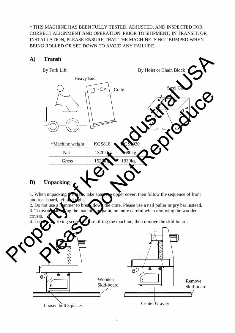
* THIS MACHINE HAS BEEN FULLY TESTED, ADJUSTED, AND INSPECTED FORCORRECT ALIGNMENT AND OPERATION. PRIOR TO SHIPMENT, IN TRANSIT, OR INSTALLATION, PLEASE ENSURE THAT THE MACHINE IS NOT BUMPED WHEN BEING ROLLED OR SET DOWN TO AVOID ANY FAILURE.
A) Transit
By Fork Lift By Hoist or Chain Block
Heavy End
Crate Steel Cable
*Machine weight KGS818 KGS1020
Net 1320kg 1680kg
Gross 1520kg 1930kg
B) Unpacking
1. When unpacking the crate, take apart the upper cover, then follow the sequence of frontand rear board, left and right. 2. Do not use a hammer to break down the crate. Please use a nail puller or pry bar instead.3. To avoid damaging the machine or paint, be more careful when removing the woodencovers. 4. Loosen the fixing screws before lifting the machine, then remove the skid-board.
Wooden Skid-board
Remove Skid-board
Loosen bolt 3 places Center Gravity
Propert
y of K
ent In
dustr
ial U
SA
Please
Do N
ot Rep
roduc
e
8
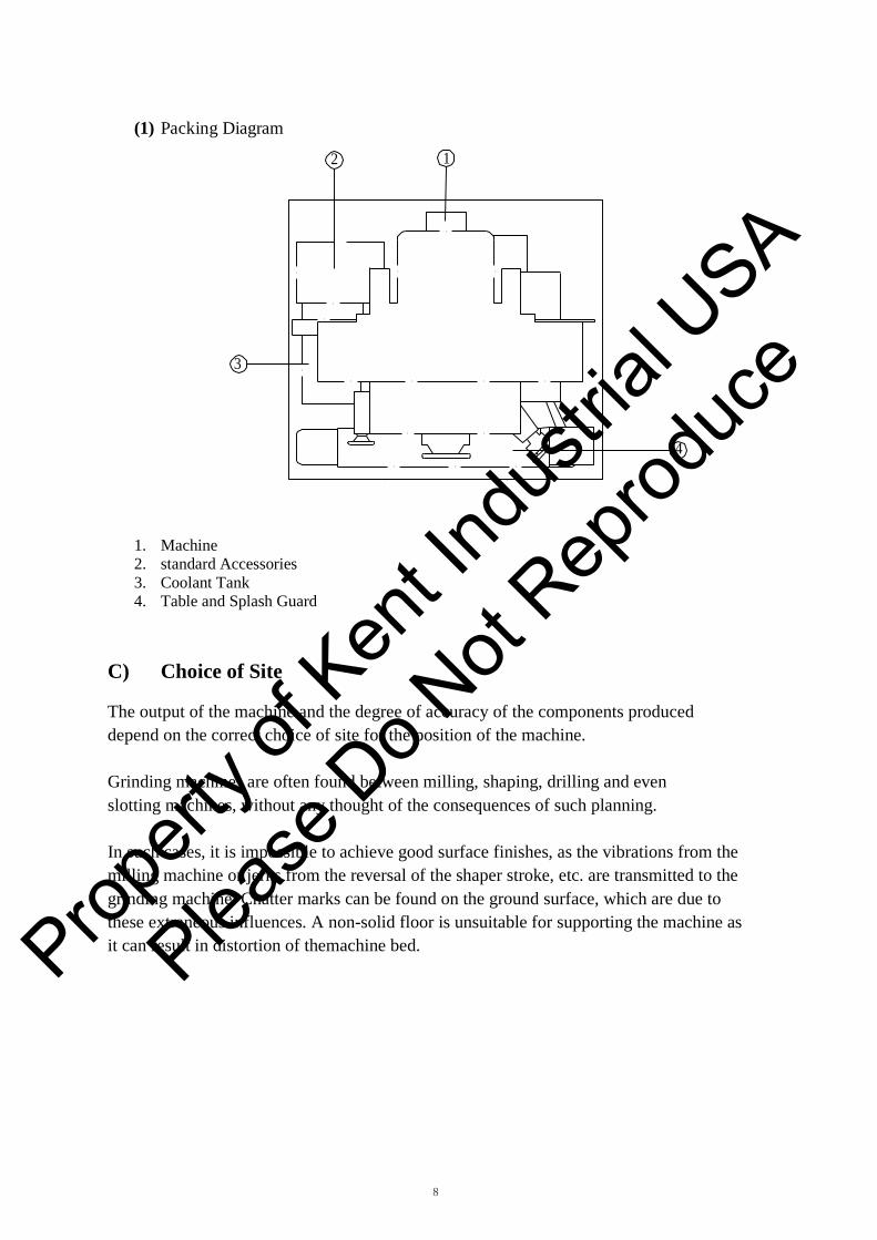
(1) Packing Diagram
2 1
3
4
1. Machine2. standard Accessories3. Coolant Tank4. Table and Splash Guard
C) Choice of Site
The output of the machine and the degree of accuracy of the components produced depend on the correct choice of site for the position of the machine.
Grinding machines are often found between milling, shaping, drilling and even slotting machines, without any thought of the consequences of such planning.
In such cases, it is impossible to achieve good surface finishes, as the vibrations from the milling machine or jerks from the reversal of the shaper stroke, etc. are transmitted to the grinding machine. Chatter marks can be found on the ground surface, which are due to these extraneous influences. A non-solid floor is unsuitable for supporting the machine as it can result in distortion of themachine bed. Prop
erty o
f Ken
t Indu
strial
USA
Please
Do N
ot Rep
roduc
e
9
Y
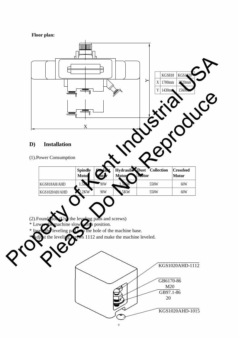
Floor plan:
KGS818 KGS1020 X 1700mm 2220mm
Y 1430mm 1560mm
X
D) Installation
(1).Power Consumption
Spindle Motor
Coolant Motor
Hydraulic Motor
Dust Collection Motor
Crossfeed Motor
KGS818AH/AHD 1.5KW 90W 1.5KW 550W 60W
KGS1020AH/AHD 2.2KW 90W 1.5KW 550W 60W
(2).Foundation (Use the leveling pads and screws) * Lower the machine slowly into position.* Insert the leveling pad into the hole of the machine base.* Adjust the leveling screws 1112 and make the machine leveled.
KGS1020AHD-1112
GB6170-86 M20
GB97.1-86 20
KGS1020AHD-1015
Propert
y of K
ent In
dustr
ial U
SA
Please
Do N
ot Rep
roduc
e
10
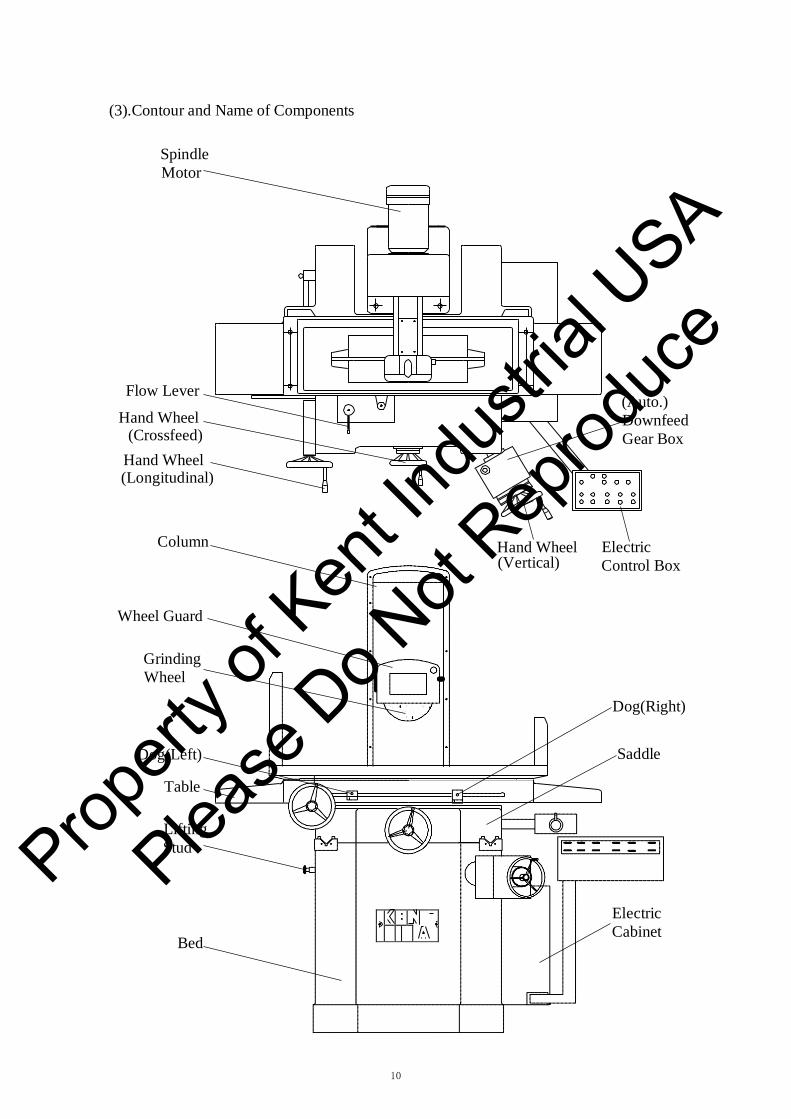
(3).Contour and Name of Components
Spindle Motor
Flow Lever
Hand Wheel (Crossfeed)
Hand Wheel (Longitudinal)
(Auto.) Downfeed Gear Box
Column Hand Wheel (Vertical)
Electric Control Box
Wheel Guard
Grinding Wheel
Dog(Left)
Table
Lifting Stud
Bed
Dog(Right)
Saddle
Electric Cabinet
Propert
y of K
ent In
dustr
ial U
SA
Please
Do N
ot Rep
roduc
e

11
(4).Cleaning Up the Machine This machine has been ensured moisture-proof, dust-proof, and rust-proof before packing. Please cleanup the machine before moving the longitudinal cross and up & down, otherwise it will affect grinding accuracy.
1
1.Guideway
1
(5).Mounting the Table a. Mounting the table
1. Put the steel ball and its retainers in the middle of slide ways.2. Place the table on the steel ball retainers.3. Install the hydraulic cylinder under the table as shown on the sketch below.
Note: Do not damage guideway, steel ball, or retainer.
Nuts Table Hydraulic Cylinder
Rubber
Saddle Cylinder Rod
1
Propert
y of K
ent In
dustr
ial U
SA
Please
Do N
ot Rep
roduc
e

12
(6).Leveling the Machine Procedure: a) Use longitudinal hand wheel to move table to the left end position. Level the machineby a Spirit Level in longitudinal and latitudinal direction (Fig.A). b) Use longitudinal hand wheel to move table to the right end position. Level the machinein the longitudinal and latitudinal direction (Fig.B).
LEVEL LEVEL
A B
c) Use cross-feed hand wheel to position the table at at front end position. Level the machineby a Spirit Level in longitudinal and latitudinal direction (Fig.C)
d) Use cross-feed hand wheel to position the table at thr rear end position. Level the machinein the longitudinal and latitudinal direction (Fig.D)
LEVEL C LEVEL D
Propert
y of K
ent In
dustr
ial U
SA
Please
Do N
ot Rep
roduc
e

13
MA
X53
0
10
23
(7).Table size and movement scope
a.KGS818AH/AHD
MAX220
200
14
24
SPECIFICATION KGS818AH/AHD
Size of working table 200mm×460mm Table traverse Longitudinal traverse 510mm
Cross traverse 250mm Distance from spindle axis to table surface 70-530mm Spindle vertical traverse 460mm Wheel size 200mm×25mm×32mm Spindle motor 2850r/min 50HZ Overall dimension(L×W×H) 1570mm×1990mm×2120mm
Propert
y of K
ent In
dustr
ial U
SA
Please
Do N
ot Rep
roduc
e

14
MA
X53
5
10
23
b.KGS1020AH/AHD
MAX276
255 14
24
SPECIFICATION KGS1020AH/AHD
Size of working table 250mm×510mm Table traverse Longitudinal traverse 575mm
Cross traverse 280mm Distance from spindle axis to table surface 70-535mm Spindle vertical traverse 460mm Wheel size 200mm×25mm×32mm Spindle motor 2850r/min 50HZ Overall dimension(L×W×H) 1680mm×2030mm×2110mm
Propert
y of K
ent In
dustr
ial U
SA
Please
Do N
ot Rep
roduc
e

15
0
0
2
(8).Lubrication
Lubrication Flow Chart
Elevation slideways Saddle "V" groove
Saddle plane 0 0 0 0 0 0
0 PJ-4
2
groove
PJ-9S Vertical leadscrew
2
Crossfeed leadscrew
Bed "V" left groove Bed "V" right groove 0 0 0
PJ-7S
Auto .lubrication pump
MMXL-Ⅲ-6/5.5-AC220
Reliability and efficiency of the machine are ensured only by the correct choice of lubricant for the individual lubricating points.
1) Lubrication pump: Auto lubrication pump will work automatically and 2.5cc lubeoil (adjustable) every 15 minutes. 2) Type of lubricant: BP, ESSO, MOBIL or SHEEL.3) Lubricant tank:1.8 liters.4) Lubricating points: "V" base (2) Cross-feed lead-screw(1) Vertical lead-screw, gear
Propert
y of K
ent In
dustr
ial U
SA
Please
Do N
ot Rep
roduc
e

16
(9).Hydraulic System
a) Hydraulic Diagram
1
5
2
3 6
4
12
7
8
M 10 9
11
1. Table Cylinder2. Control Valve3. Downfeed Cylinder4. Downfeed Solenoid Valve5. Clutch Engage Cylinder6. Clutch Engage Solenoid Valve7. Pressure Gauge8. Check Valve9. Hydraulic Pump10. Hydraulic Motor11. Hydraulic Tank12. Sequence Valve
Propert
y of K
ent In
dustr
ial U
SA
Please
Do N
ot Rep
roduc
e

17
b) Hydraulic OilHydraulic tank volume: 51.3 liters Re-fill frequency: After the first month, clean the hydraulic tank and change the oil every six months. Hydraulic oil:
CPC BP ESSO MOBIL MOBIL R-68 ENGRGOL ESSTIC 50 D.T.E OIL SHELL
HL100 Medium Tellus oil 29 4.5 E/50 C 4.7 E/50 C 3.93 E/50 C 4.0 /50 C 33cst/50 C 35cst/50 C 28.9cst/50 C 29cst/50 C
*Fill up the oil tank before starting the hydraulic motor.*Please ensure that there are no people or objects within the range of the table movementbefore starting the longitudinal travel. *Maximum hydraulic pressure: 22 kgs/cm ².*Filter must be cleaned when changing oil. If broken, the filter must be replaced.
Propert
y of K
ent In
dustr
ial U
SA
Please
Do N
ot Rep
roduc
e

18
1
2 5 3 6
4
Description:
(1). Rear limit:SQ3
(2). Front limit:SQ2
(3). Rear reversal limit:SQ1
(4). Front reversal limit:SQ4
(5). Auto.down feed switch:SQ5
(6). Auto.cross feed switch:SQ6
For above-mentioned cord no.,please refer to Circuit
Diagram.
(10).Limit Switch Position
Description:(1). Rear limit:SQ3(2). Front limit:SQ2(3). Rear reversal limit:SQ1(4). Front reversal limit:SQ4(5). Auto.down feed switch:SQ5(6). Auto.cross feed switch:SQ6For above-mentioned cord no.,please refer to Circuit Diagram.
123
4
Propert
y of K
ent In
dustr
ial U
SA
Please
Do N
ot Rep
roduc
e

19
(11).Balancing the Grinding Wheel Efficient balancing is essential in eliminating unnecessary stress in the wheel. It can also help obtain high quality surface finishes, grinding accuracy, and extend the life of the grinding wheel. In this case, the grinding wheel has to be balanced carefully. Static balancing can better meet the requirements of machining.
The grinding wheel together with the wheel flange is fitted to balance the arbor and this assembly is then placed on two accurate parallel knife edges of the wheel balancing base, and balancing can be effected as follows: (see Fig.2).
• The wheel balancing base must be leveled (Fig.1)
• Allow the wheel to oscillate to find the center of gravity, which is then marked "S"with chalk (Fig.3)
• Apply the first balancing weight "G" opposite to this point "S" and screw it in. Itcannot be moved again (Fig.4)
• Place two correction weight "K" anywhere around the periphery, but at equaldistance "a" from weight "G" (Fig 5)
• Turn the wheel 90° at a time and see if it is balanced. If it is not, the correctionweight "K" must be moved until the wheel is balanced in any position (Fig. 6)
• After balancing, the wheel must be given a test run of at least five minutes at fullworking speed before being used or fine balanced.
Level
Wheel
Flange
Base
Balancing Arbor
S
Fig.1 Fig.2 Fig.3
G K
G K
Fig.4 S S
Fig.5 Fig.6
Propert
y of K
ent In
dustr
ial U
SA
Please
Do N
ot Rep
roduc
e
20
After being balanced for the first time, the wheel must be mounted on the grinding spindle of the machine and dressed. This can be done with the parallel dresser on the spindle carrier or with one fitted on the table. When dressing the wheel from the table, the table must be locked longitudinally and then cross-traversed with the hand-wheel. The wheel must be dressed until it runs dead true. The grinding finish is improved, if any part of the wheel is out-of -truth in the side walls, the wheel is also removed.
After this first balancing, the wheel must be removed from the spindle again and then carefully re-dressed. After being fitted to the spindle again and re-dressed, it is ready for use.
As wear can lead to unbalance, the wheel should be re-checked and if necessary, rebalanced.
Grinding wheel absorbs humidity and coolant, it is therefore advisable not to short the coolant supply when the wheel is stationary, otherwise the wheel will absorb liquid on one side only and will then be out of balance. If the wheel is allowed to stand for any length of time, coolant will collect at the lowest point. Idling is essential to throw-off coolant by centrifugal force.
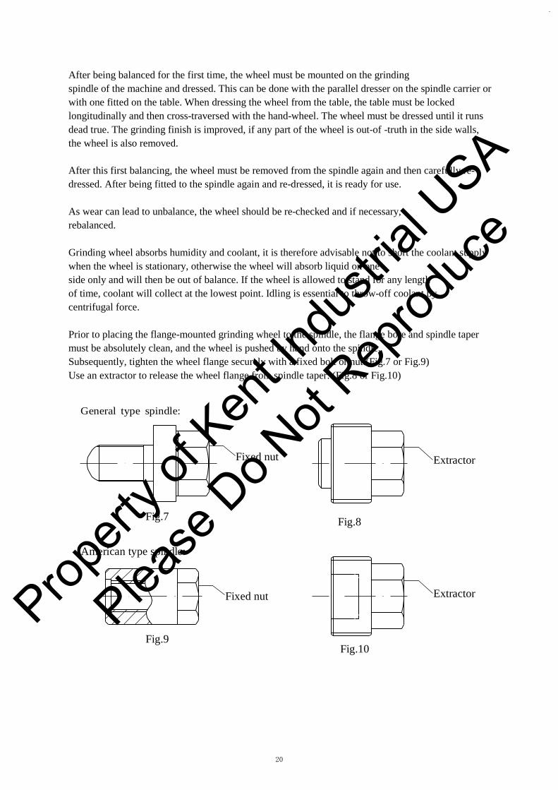
Prior to placing the flange-mounted grinding wheel to the spindle, the flange bore and spindle taper must be absolutely clean, and the wheel is pushed by hand onto the spindle. Subsequently, tighten the wheel flange securely with a fixed bolt or nut.(Fig.7 or Fig.9) Use an extractor to release the wheel flange from spindle taper. (Fig.8 or Fig.10)
General type spindle:
Fixed nut Extractor
Fig.7 Fig.8
American type spindle:
Fixed nut Extractor
Fig.9 Fig.10
Propert
y of K
ent In
dustr
ial U
SA
Please
Do N
ot Rep
roduc
e

21
*If various materials have to be grounded, so that the wheel has to be changed frequently, it ismore advantageous to change the wheel completely with a flange. It would save you time from removing the wheel from its mount each time to re-balance and re-dress it.
E) Putting The Machine Into Operation
(1).Wiring of power source Be sure that the wire connection is same as your power source before you power "ON" the machine.
Box B
Box A
Box C
Box A: Electric cabinet Box B: Three-phase transformer for: 1. Cross motor2. Solenoid valve3. Electromagnetic chuck4. Auto lubrication pumpBox C: Control panel and control circuit
Attention:Following motors must be wired in accordance with power source voltage.
1. Spindle motor2.Hydraulic motor3.Coolant or dust-collector motor(Optional accessory)
a. For 440V power source:
Box B
Box A 460
460
460
210
210
210
U6 V6 W6 U V W
Power Source
Propert
y of K
ent In
dustr
ial U
SA
Please
Do N
ot Rep
roduc
e

22
b. For U.S.A area:
200V to 220V power source:
Box A
U6 V6 W6 U V W
Box B 460 460 460 230 230 230
210 210 210
Power Source
220V to 240V power source:
Box A
U6 V6 W6 U V W
Box B 460 460 460 230 230 230
210 210 210
Power Source
440V to 460V power source:
Box A
U6 V6 W6 U V W
Box B 460 460 460 230 230 230
210 210 210
Power Source
Propert
y of K
ent In
dustr
ial U
SA
Please
Do N
ot Rep
roduc
e
23
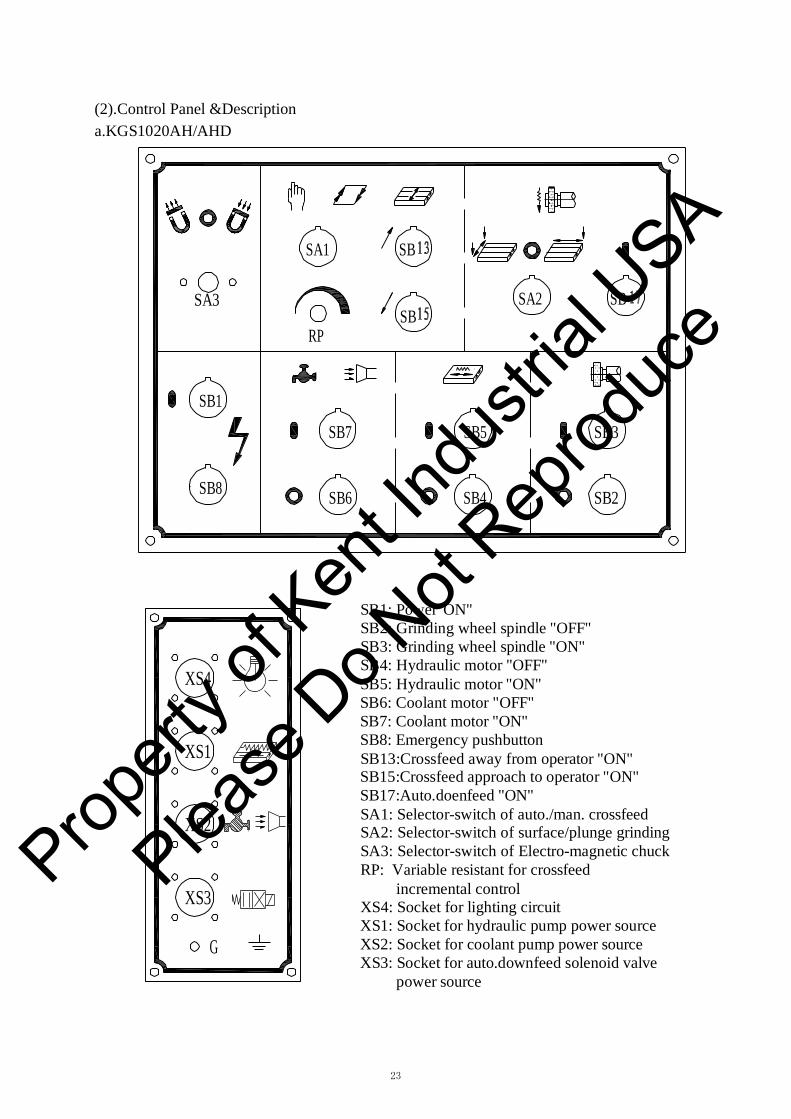
(2).Control Panel &Description a.KGS1020AH/AHD
SA1 SB
SA3 SB
RP
SA2 SB
SB1
SB8
SB7
SB6
SB5
SB4
SB3
SB2
XS4
XS1
XS2
XS3
G
SB1: Power"ON" SB2: Grinding wheel spindle "OFF" SB3: Grinding wheel spindle "ON" SB4: Hydraulic motor "OFF" SB5: Hydraulic motor "ON" SB6: Coolant motor "OFF" SB7: Coolant motor "ON" SB8: Emergency pushbutton SB13:Crossfeed away from operator "ON" SB15:Crossfeed approach to operator "ON" SB17:Auto.doenfeed "ON" SA1: Selector-switch of auto./man. crossfeed SA2: Selector-switch of surface/plunge grinding SA3: Selector-switch of Electro-magnetic chuck RP: Variable resistant for crossfeed
incremental control XS4: Socket for lighting circuit XS1: Socket for hydraulic pump power source XS2: Socket for coolant pump power source XS3: Socket for auto.downfeed solenoid valve
power source
Propert
y of K
ent In
dustr
ial U
SA
Please
Do N
ot Rep
roduc
e
24
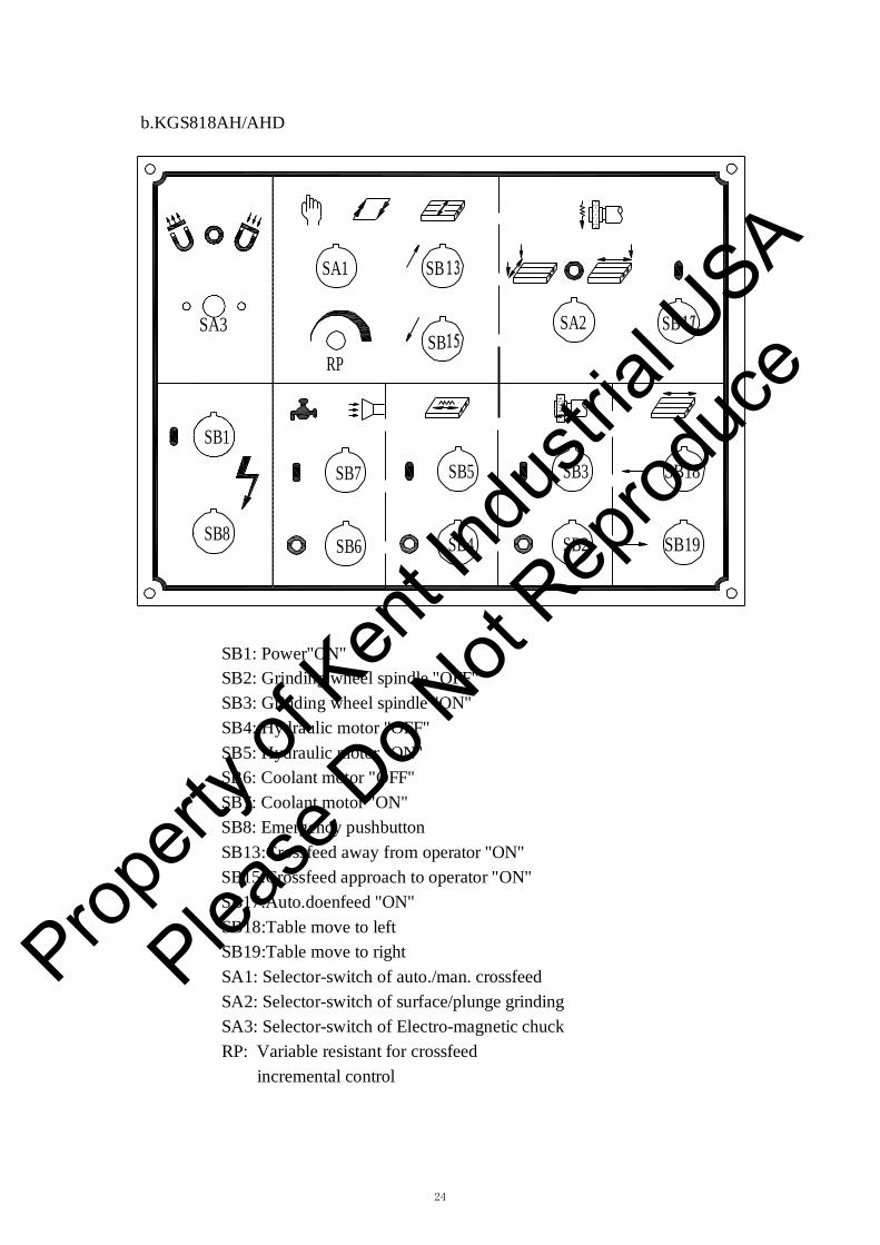
b.KGS818AH/AHD
SA1 SB
SA3 SB
RP
SA2 SB
SB1
SB8
SB7
SB6
SB5
SB4
SB3
SB2
SB18
SB19
SB1: Power"ON" SB2: Grinding wheel spindle "OFF" SB3: Grinding wheel spindle "ON" SB4: Hydraulic motor "OFF" SB5: Hydraulic motor "ON" SB6: Coolant motor "OFF" SB7: Coolant motor "ON" SB8: Emergency pushbutton SB13:Crossfeed away from operator "ON" SB15:Crossfeed approach to operator "ON" SB17:Auto.doenfeed "ON" SB18:Table move to left SB19:Table move to right SA1: Selector-switch of auto./man. crossfeed SA2: Selector-switch of surface/plunge grinding SA3: Selector-switch of Electro-magnetic chuck RP: Variable resistant for crossfeed
incremental control
Propert
y of K
ent In
dustr
ial U
SA
Please
Do N
ot Rep
roduc
e

25
(3) Operation a. Before operationIt's only after the following instructions have been fully complied with that the machine can be started: 1. Choice of a location free from vibration.2. Clean up the machine of those anti-rust oil and grease.3. Installation of the machine according to lubrication instruction.4. Lubrication of the machine according to lubrication instruction.5. Check the spindle(wheel) rotation direction, must be clockwise. Please take off the wheelprior to starting the spindle or it will cause danger if it rotates counter-clockwise. 6. Fill the hydraulic tank with suitable oil.7. Hydraulic cylinder must be sealed.8. Adjust the trip dog of the table. The longitudinal trip dog is located on the front side oftable. The distance can be adjusted by loosening the screw, sliding the trip dog and fastening the screw again. 9. Caution: Please check that your power source can meet the required capacity of themachine.
b.Operation1) Power ON & OFF1. Press "QF" power switch.2. Press SB1,the electric control box is ready.3. Press SB8 to cut off power. Re-set SB8 for power "ON".
2) Table longitudinal travel1. Press SB5 to start hydraulic motor.2. Turn the flow control lever clockwise until table moves slowly, when it turns 90° it gets themax table speed. 3. If the table starts jerking, there is air in the hydraulic section of the table and it should beoperated at max travel reciprocally.
Propert
y of K
ent In
dustr
ial U
SA
Please
Do N
ot Rep
roduc
e

26
3).Cross travel 1.Turn SA1 to left, press SB13, saddle moves away from operator continuously; press SB15,saddle moves close to operator continuously. This function is only effective when SA1 is in left position (surface grinding), it can't start in right position for vertical feed grinding.
2.Turn SA1 to right, press SB15 or SB13 and release, adjust RP, the saddle feedsautomatically when surface grinding. By adjusting trip dog to change its direction when SA1 changes to left, this function can be interrupted at once. The cross-feed distance can be changed by setting the distance of trip dogs' located on the left side of the machine base.
3.In addition, there are two limit switches on the left side of machine base to limit themaximum cross travel of the saddle. They are also used as a safety device in case of an accident when cross-feed mechanism fails.
4).Automatic downfeed control
1. Turn selector switch SA2 on (plunge grinding) position, press push-button
SB17 then grinding wheel will auto down-feed when table longitudinal traverse at left end;
turn selector switch SA2 on (surface grinding) position, press
push-button SB17 then grinding wheel will auto down-feed when table longitudinal traverse at left end; turn selector switch SA2 on (surface grinding) position, press SB17,then grinding wheel will auto down-feed at both ends of cross-feed travel; turn
selector switch SA2 on position, grinding wheel will stop auto down-feed.
2. Down-feed increment can be preset by preset dial at0.0001,0.0002,0.0003,0.0004,0.0005,0.0006,0.0007,0.0008,0.0009,0.001 inch,10 steps. Figure below is a down-feed increment to be set at 0.0005 inch.
Preset dial 0
5
0.0001″ 10
Propert
y of K
ent In
dustr
ial U
SA
Please
Do N
ot Rep
roduc
e
27
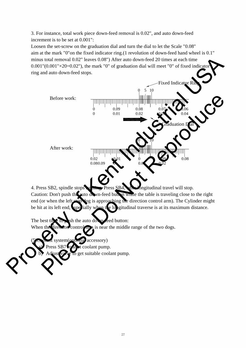
3. For instance, total work piece down-feed removal is 0.02", and auto down-feedincrement is to be set at 0.001": Loosen the set-screw on the graduation dial and turn the dial to let the Scale "0.08" aim at the mark "0"on the fixed indicator ring.(1 revolution of down-feed hand wheel is 0.1" minus total removal 0.02" leaves 0.08") After auto down-feed 20 times at each time 0.001"(0.001"×20=0.02"), the mark "0" of graduation dial will meet "0" of fixed indicator ring and auto down-feed stops.
Before work:
0 5 10
Fixed Indicator Ring
0 0.09 0.08 0.07 0.06 0 0.01 0.02 0.03 0.04
Graduation Dial
After work: 0 5 10
0.02 0.01 0 0.09 0.08 0.08 0.09 0 0.01 0.02
4. Press SB2, spindle stops running. Press SB4, table longitudinal travel will stop.Caution: Don't push the auto down-feed button while the table is traveling close to the right end (or when the left stop dog is approaching the direction control arm). The Cylinder might be hit at its left end, especially when the longitudinal traverse is at its maximum distance.
The best time to push the auto down-feed button: When the direction control arm is near the middle range of the two dogs.
(5)Coolant system(optional accessory) a) Press SB7 to start coolant pump.b) Adjust valve to get suitable coolant pump.
Propert
y of K
ent In
dustr
ial U
SA
Please
Do N
ot Rep
roduc
e
28
F) GrindingThe grinding results obtained depend to a very large degree on the choice of the correct grinding wheel and suitable operation.
(1)Stock removal efficiency For intensive stock removal, a coarse grain(about 30-36)should be used. The wheel is dressed by passing the diamond over quickly so that the surface of the wheel is roughed and bites well.
(2)Surface finish required If fine finish is to be produced, a finer grain wheel is required (40-80).The diamond in this case is passed slowly over the wheel to break up the grain.
(3)Distortion of the workpiece If the workpiece shows too much distortion when being ground, this means that the stock removal was too great and the longitudinal and cross movements of the table were too slow,or the grinding wheel is "clogged".
(4)Undesirable burns and grinding cracks If burn marks and grinding cracks appear, this means that the wheel is too hard, or thewheel is "clogged".
G) Wheel InspectionIt is absolutely essential to fully comply with the following safety rules. These are intended to protect the operator against danger. Wheel inspection and fitting:
Prior to fitting any grinding wheel, it should always be tested. Sounding the wheel is a generally accepted test method. The wheel should be suspended from a mandrel secured to its bore and should then be lightly sounded with a wooden hammer. Even wheels with hair cracks not visible with the bare eye will produce a distorted sound in comparison with a perfect wheel where the sound is clear. Defective grinding wheel must not be used.
There are two pieces of paper washer on both faces of the wheel, which serve as plastic packing between the wheel and mounting flange.
The packing washer must not be removed. When mounting the wheel, it should slide onto the flange easily by hand without the need for force. The wheel flange must be absolutely clean, especially on the clamping and location surface in the spindle bore and thread. Prop
erty o
f Ken
t Indu
strial
USA
Please
Do N
ot Rep
roduc
e

29
H) Dressing The Wheel And Correct Treatment Of Dressing Diamond
The diamond is inserted in the dressing device. The sleeve of the device is arranged at an angle of about 5°, so that, when the diamond loses its keenness, it can be turned in the sleeve, along with its holder, thus ensuring that there is always a sharp diamond edge available. Various degrees of roughness can be produced in the ground component by varying the speed at which the diamond is passed over the grinding wheel.
If there is only about 0.2mm to 0.3mm stock removal, it is advisable to roughen the grinding wheel. This is done by feeding the diamond in about 0.03mm and turning the hand-wheel rapidly, so that the dressing diamond moves quickly over the wheel. This makes the wheel bite well and the stock removal is good.
If the component is to be finish ground to size with the same grinding wheel, the wheel must be dressed again, this time slowly in two or three passes, with the diamond fed in only about 0.01mm.
Frequent light dressing is better for life of the grinding wheel and the diamond than a heavy cut.
When dressing, the diamond should always be cooled, if possible, but sudden cooling is dangerous, as it can lead to the diamond being split.
As the diamond is very brittle because of its extraordinary hardness and sensitivity to even the slightest knock, it cracks easily.
When dressing, begin in the center as the edges are usually worn down more. If dressing is begun at the worn edges, there is danger of the higher pressure in the center over stressing the diamond and shattering it.
Propert
y of K
ent In
dustr
ial U
SA
Please
Do N
ot Rep
roduc
e
30
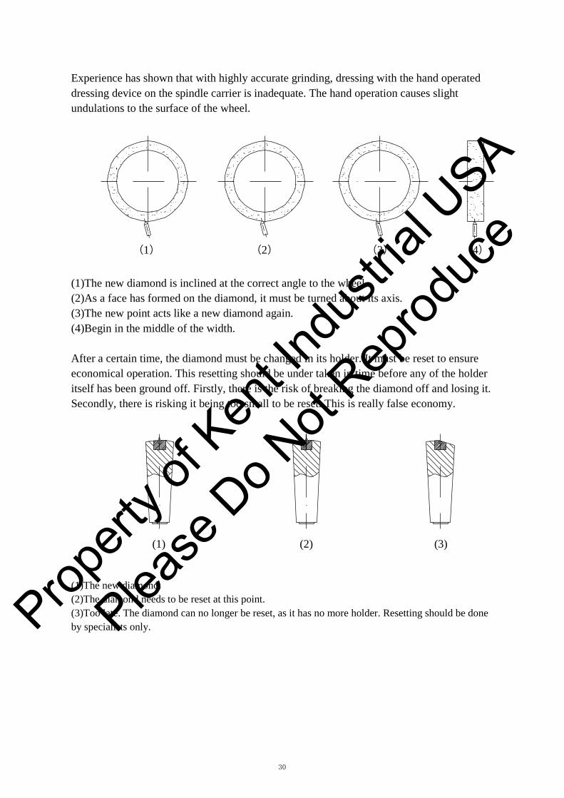
Experience has shown that with highly accurate grinding, dressing with the hand operated dressing device on the spindle carrier is inadequate. The hand operation causes slight undulations to the surface of the wheel.
(1) (2) (3) (4)
(1)The new diamond is inclined at the correct angle to the wheel. (2)As a face has formed on the diamond, it must be turned about its axis. (3)The new point acts like a new diamond again. (4)Begin in the middle of the width.
After a certain time, the diamond must be changed in its holder. It must be reset to ensure economical operation. This resetting should be under taken in time before any of the holder itself has been ground off. Firstly, there is the risk of breaking the diamond off and losing it. Secondly, there is risking it being too small to be reset. This is really false economy.
(1) (2) (3)
(1)The new diamond. (2)The diamond needs to be reset at this point. (3)Too late. The diamond can no longer be reset, as it has no more holder. Resetting should be done by specialists only. Prop
erty o
f Ken
t Indu
strial
USA
Please
Do N
ot Rep
roduc
e
31
I) Storage of Grinding Wheel
The wheels should be kept in special racks in a dry place and must be protected from knocks and jolts, especially when they are being transported. As a rule, they should be stood on edge, but thin wheels and wheels with a sharp edge must be laid flat on an even surface. Grinding wheels must not be allowed to come into contact with oil or grease. An oil soaked wheel loses its bite and its application is very limited.
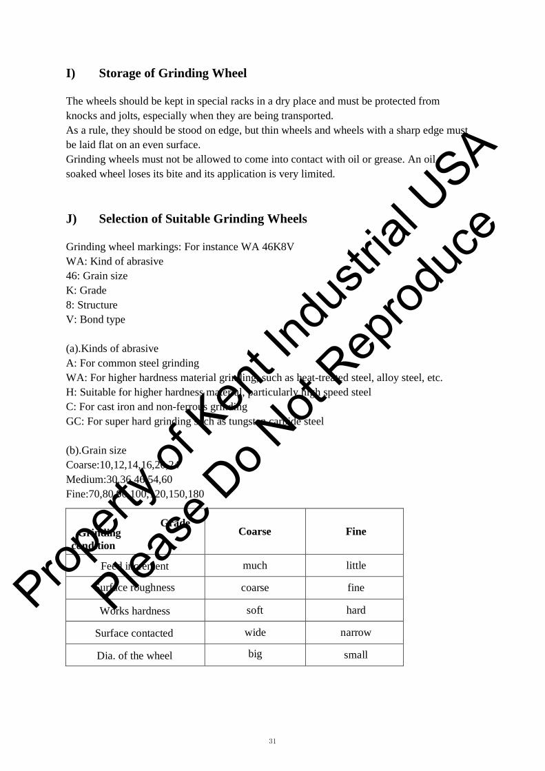
J) Selection of Suitable Grinding Wheels
Grinding wheel markings: For instance WA 46K8V WA: Kind of abrasive 46: Grain size K: Grade 8: Structure V: Bond type
(a).Kinds of abrasive A: For common steel grinding WA: For higher hardness material grinding, such as heat-treated steel, alloy steel, etc. H: Suitable for higher hardness material, particularly high speed steel C: For cast iron and non-ferrous grinding GC: For super hard grinding such as tungsten carbide steel
(b).Grain size Coarse:10,12,14,16,20,24 Medium:30,36,46,54,60 Fine:70,80,90,100,120,150,180
Grade Grinding
condition Coarse Fine
Feed increment much little
Surface roughness coarse fine
Works hardness soft hard
Surface contacted wide narrow
Dia. of the wheel big small
Propert
y of K
ent In
dustr
ial U
SA
Please
Do N
ot Rep
roduc
e
32
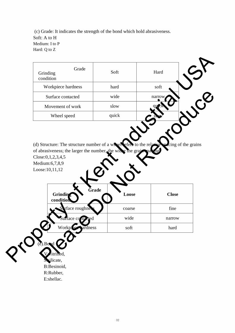
(c) Grade: It indicates the strength of the bond which hold abrasiveness. Soft: A to H Medium: I to P Hard: Q to Z
(d) Structure: The structure number of a wheel refers to the relative spacing of the grains of abrasiveness; the larger the number, the wider the grain spacing. Close:0,1,2,3,4,5 Medium:6,7,8,9 Loose:10,11,12
Grade Grinding
condition Loose Close
Surface roughness coarse fine
Surface contacted wide narrow
Workpiece hardness soft hard
(e).Bond
V:vitrified, S:silicate, B:Besinoid, R:Rubber, E:shellac.
Grade Grinding condition
Soft Hard
Workpiece hardness hard soft
Surface contacted wide narrow
Movement of work slow quick
Wheel speed quick slow
Propert
y of K
ent In
dustr
ial U
SA
Please
Do N
ot Rep
roduc
e
33
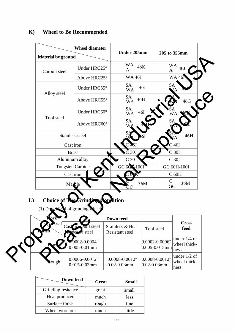
Wheel diameter
Material be ground Under 205mm 205 to 355mm
Carbon steel Under HRC25°
WA WA 46J
Above HRC25° WA 46J WA 46I
Alloy steel Under HRC55° SA SA
Above HRC55° SA SA
Tool steel Under HRC60° SA SA
Above HRC60° SA SA
Stainless steel SA SA
Cast iron C 46J C 46I Brass C 30J C 30I
Aluminum alloy C 30J C 30I Tungsten Carbide GC 60H-100I GC 60H-100I
Cast iron C 60K C 60K
Marble C C
K) Wheel to Be Recommended
A A
WA WA
WA WA
WA WA
WA WA
WA WA
L) Choice of The Grinding Condition(1).Down feed of grinding wheel
Work material
Finish
Down feed Cross feed Cast iron,Soft steel
,Hardened steel Stainless & Heat Resistant steel
Tool steel
Fine 0.0002-0.0004" 0.005-0.01mm
0.0002-0.0006" 0.005-0.015mm
under 1/4 of wheel thick- ness
Rough 0.0006-0.0012" 0.015-0.03mm
0.0008-0.0012" 0.02-0.03mm
0.0008-0.0012" 0.02-0.03mm
under 1/2 of wheel thick- ness
Down feed Great Small
Grinding resitance great small Heat produced much less Surface finish rough fine
Wheel worn out much little
46K
46J
46H
46I
46H
46I
36M 36MGC GC
46I
46G
46H
46H
46H
Propert
y of K
ent In
dustr
ial U
SA
Please
Do N
ot Rep
roduc
e

34
(2).Cross feed
Cross feed Great Small
Grinding resitance great small Heat produced much less Surface finish rough fine
Wheel worn out much little
(3).Longitudinal feed
Table traverse Quick Slow
Grinding resitance great small Heat produced less much Surface finish rough fine
Wheel worn out much little
Suitable speed of the table traverse
Workpiece material Soft steel Heat treated steel Tool steel Cast iron Speed:m/min 6-15 20-25 6-25 16-20
(4).Rauge of spindle speed:1200-1800m/min
Spindle speed Condition
Quick Slow
Grinding resistance small big Heat produced much less Surface finish fine rough
Wheel worn out small great Safety bad good
Material Rauge speed
Steel 20-30m/s
Cast iron 18-20m/s
Tungsten carbide 8-18m/s
Zinc alloy and light metal 25-30m/s
Propert
y of K
ent In
dustr
ial U
SA
Please
Do N
ot Rep
roduc
e
35
M) Use of the Optional Attachment
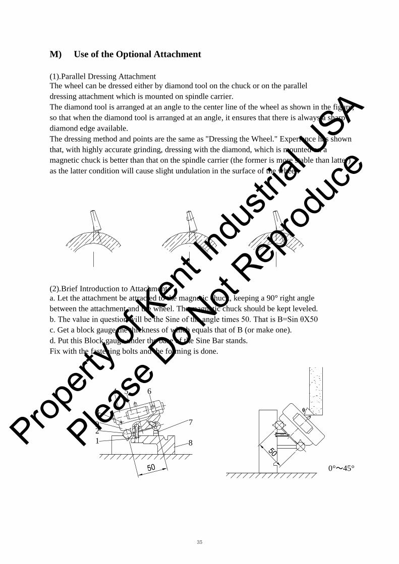
(1).Parallel Dressing Attachment The wheel can be dressed either by diamond tool on the chuck or on the parallel dressing attachment which is mounted on spindle carrier. The diamond tool is arranged at an angle to the center line of the wheel as shown in the figure, so that when the diamond tool is arranged at an angle, it ensures that there is always a sharp diamond edge available. The dressing method and points are the same as "Dressing the Wheel." Experience has shown that, with highly accurate grinding, dressing with the diamond, which is mounted on a magnetic chuck is better than that on the spindle carrier (the former is more stable than latter) as the latter condition will cause slight undulation in the surface of the wheel.
(2).Brief Introduction to Attachment a. Let the attachment be attracted to the magnetic chuck, keeping a 90° right anglebetween the attachment and the wheel. The magnetic chuck should be kept leveled. b. The value in question will be the Sine of the angle times 50. That is B=Sin θX50c. Get a block gauge the thickness of which equals that of B (or make one).d. Put this Block gauge under the base of the Sine Bar stands.Fix with the fastening bolts and the forming is done.
4 5 6
3 9 7 21 8
0°~45°
Propert
y of K
ent In
dustr
ial U
SA
Please
Do N
ot Rep
roduc
e
36
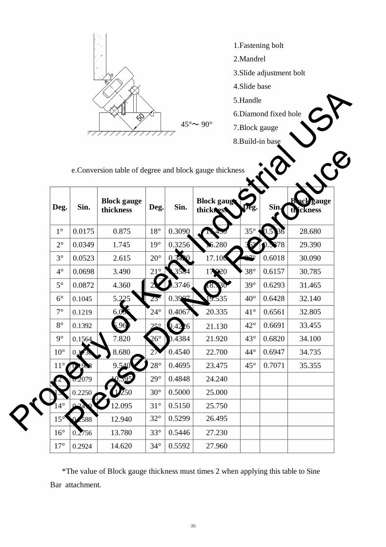
θ
45°~ 90°
1.Fastening bolt
2.Mandrel
3.Slide adjustment bolt
4.Slide base
5.Handle
6.Diamond fixed hole
7.Block gauge
8.Build-in base
e.Conversion table of degree and block gauge thickness
Deg. Sin. Block gauge thickness Deg. Sin.
Block gauge thickness Deg. Sin.
Block gauge thickness
1° 0.0175 0.875 18° 0.3090 15.450 35° 0.5736 28.680
2° 0.0349 1.745 19° 0.3256 16.280 36° 0.5878 29.390
3° 0.0523 2.615 20° 0.3420 17.100 37° 0.6018 30.090
4° 0.0698 3.490 21° 0.3584 17.920 38° 0.6157 30.785
5° 0.0872 4.360 22° 0.3746 18.730 39° 0.6293 31.465
6° 0.1045 5.225 23° 0.3907 19.535 40° 0.6428 32.140
7° 0.1219 6.095 24° 0.4067 20.335 41° 0.6561 32.805
8° 0.1392 6.960 25° 0.4226 21.130 42° 0.6691 33.455
9° 0.1564 7.820 26° 0.4384 21.920 43° 0.6820 34.100
10° 0.1736 8.680 27° 0.4540 22.700 44° 0.6947 34.735
11° 0.1908 9.540 28° 0.4695 23.475 45° 0.7071 35.355
12° 0.2079 10.395 29° 0.4848 24.240
13° 0.2250 11.250 30° 0.5000 25.000
14° 0.2419 12.095 31° 0.5150 25.750
15° 0.2588 12.940 32° 0.5299 26.495
16° 0.2756 13.780 33° 0.5446 27.230
17° 0.2924 14.620 34° 0.5592 27.960
*The value of Block gauge thickness must times 2 when applying this table to Sine
Bar attachment.
Propert
y of K
ent In
dustr
ial U
SA
Please
Do N
ot Rep
roduc
e

37
(3).Sine Bar The Sine Bar is used to chuck the inclined angle of the magnetic chuck when the angle forming surface is large. a. The value in question equals the Sine of the angle times 100, B=Sin θ x100b. Get a block gauge the thickness of which equals that of B.c. Put this gauge at one end of the Sine Bar and let it be attracted to the inclined magneticchuck. This Sine Bar shall be kept parallel to the longitudinal direction of the machine. d. Press the dial gauge against the surface of the Sine Bar and meanwhile turn thecross-feed hand-wheel, so that the saddle moves back and forth for the checking of the accuracy of the magnetic chuck.
4 1 2
3
7
100mm 6
5
1. Mandrel 5.Inclincalb Magnetic Chuck
2. Sine Bar 6.Mandrel of the Magnetic Chuck
3. Block gauge 7.Stop block
4. Application of the trigonometry
(4).Radius Forming Attachment
The radius Forming Attachment is composed of a main stand,several swing rods
and a diamond tool. a. Main Stand
Fastening bolt
Mandrel Propert
y of K
ent In
dustr
ial U
SA
Please
Do N
ot Rep
roduc
e

38
R
B
A
X
A
B
B
R
X
R
A
B
b. Swing rod and diamond tool
Center
Diamond tool
Fastening bolt
Name plate is attached to swing rod with the A and B to mean: A: the distance between the upper rim and the center B: the distance between the bottom rim and the center The R forming is the adjustment of the distance between the diamond tool and the swing rod center so that the R shaping results.
c. To determine the concave and convex R:1. If the tool is parallel to the center line, it equals OR.2. To determine the convex R: Put the swing rod on a place disk.Put a block gauge of proper thickness under the diamond tool. Then R=X-A 3. To determine the small concave, R=A-X
d. To determine the big concave R:R=B+X
Workpiece
Same thickness block gauge(X)
Propert
y of K
ent In
dustr
ial U
SA
Please
Do N
ot Rep
roduc
e
39
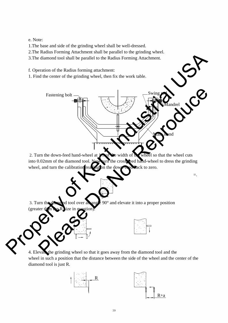
e. Note:1.The base and side of the grinding wheel shall be well-dressed.2.The Radius Forming Attachment shall be parallel to the grinding wheel.3.The diamond tool shall be parallel to the Radius Forming Attachment.
f. Operation of the Radius forming attachment:1. Find the center of the grinding wheel, then fix the work table.
Fastening bolt Swing rod
Mandrel
Main stand
2. Turn the down-feed hand-wheel at 1/3 of the width of the wheel so that the wheel cutsinto 0.02mm of the diamond tool. Now turn the cross-feed hand-wheel to dress the grinding wheel, and turn the calibration reading on the down-feed back to zero.
=.
3. Turn the diamond tool over an angle 90° and elevate it into a proper position(greater than the R size in question).
4. Elevate the grinding wheel so that it goes away from the diamond tool and thewheel in such a position that the distance between the side of the wheel and the center of the diamond tool is just R.
R
R+a
Propert
y of K
ent In
dustr
ial U
SA
Please
Do N
ot Rep
roduc
e

40
R
5. Move the diamond tool (R+a) leftward, with "a" found in the following table.
R 5
4 3
2
1 a
0 0.02 0.04 0.08 0.15 0.20
6. Turn the down-feed hand-wheel so that the grinding wheel approaches the diamond tool.
7. Turn the swing rods 90° each time, moving 0.05mm till the R is determined.
8. The wheel finally becomes the following shape.
R+a
(5) Coolant System Insert the power source plug into the socket (at the rear side of electric control box). Press the push-button switch to start the coolant pump. The pump should rotate in clockwise direction, if not, interchange any two cords of three-cord electrical cable. Adjust coolant flow by turning the ball valve to suitable rate.
Cooling water is collected from table and returns to coolant tank through return hose then filtered in the coolant tank by turns of cabinet #1,2,3. *Coolant tank capacity:46 liters*Coolant pump:90Wx2P
Propert
y of K
ent In
dustr
ial U
SA
Please
Do N
ot Rep
roduc
e

41
2
1 3
(6).Common cases in Side Grinding
In the case shown in the figure above, the side-grinding wheel and the work have a smaller contact surface, in which case the efficiency is higher, and the surface roughness is better.
In the figure above, the wheel and the work have two sections of contact, and the surface of grinding is bad. The surface has to be corrected into the shape shown in 1.
The wheel did not cut to "Relief Angle," thus it contacts the whole face of the work, causing the surface of processing to be rough and rugged. Also, the greater face of contact will cause burns and cracks. Prop
erty o
f Ken
t Indu
strial
USA
Please
Do N
ot Rep
roduc
e

42
The "Relief Angle" of the wheel is lower than the surface of the work, so that the work face becomes two sections, the upper section resembling that in 3 and the lower section in 1.
Now it is necessary to enlarge the "Relief Angle" part so that it will be higher than the face of the work. e. If the spindle does not constitute a right angle with the work table surface, themachined surface will turn out to be as shown.
(7).Right Angle Grinding a.Tools
Angle gauge Block Clamp Clamp
Inclinable Magnetic Chuck Block gauge Clamp
b. Use of the jigs and tools: take the grinding of the block of six faces A, B, C, D, E, F.For example: 1. Under 200mm:*Grinding of the first basic face, or the surface grinding of A and B.
C
E F A B A
B D
Propert
y of K
ent In
dustr
ial U
SA
Please
Do N
ot Rep
roduc
e
43
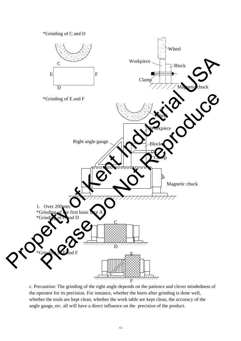
C
*Grinding of C and D
Wheel
Workpiece Block
E F Clamp
D Magnetic chuck
*Grinding of E and F
Wheel
Workpiece
Right angle gauge Block
Clamp
Magnetic chuck
1. Over 200mm:*Grinding of the first basic face A*Grinding of C and D
C
D *Grinding of E and F E
F c. Precaution: The grinding of the right angle depends on the patience and clever mindedness ofthe operator for its precision. For instance, whether the burrs after grinding is done well, whether the tools are kept clean, whether the work table are kept clean, the accuracy of the angle gauge, etc. all will have a direct influence on the precision of the product.
Propert
y of K
ent In
dustr
ial U
SA
Please
Do N
ot Rep
roduc
e
44
N) Complete Knock Down Drawings & Parts Lists
WHEN ORDERING PARTS,PLEASE MENTION: 1.MACHINE MODEL & SERIAL NUMBER INDEX NUMBER
PARTS NO.AND PARTS NAME
4.QUANTITY
CONTENTS Bed,Saddle,Table Ass'y .................................................................................................. 45 Column Ass'y. .............................................................................................................. 47 Auto Downfeed Ass'y ................................................................................................... 49 Manual Downfeed Ass'y ............................................................................................... 54 Spindle Ass'y ................................................................................................................ 57 Auto Crossfeed Ass'y. ................................................................................................... 59 Crossfeed Control Limit Switch. ................................................................................... 62 Cylinder Ass'y. ............................................................................................................. 64 Valve Ass'y .................................................................................................................. 66 Hydraulic Tank Ass'y. ................................................................................................... 68 Coolant System ............................................................................................................. 74 Qualifide Certification .................................................................................................. 76 Packing List .................................................................................................................. 80
Propert
y of K
ent In
dustr
ial U
SA
Please
Do N
ot Rep
roduc
e

4
3
12
6
7
9
7
8
109
8 10
1
2
11
5
134
3
12
6
7
9
7
8
109
8 10
1
2
11
5
13
45
Propert
y of K
ent In
dustr
ial U
SA
Please
Do N
ot Rep
roduc
e

46
BED, SADDLE , TABLE ASS’Y
(KGS818AH/AHD,KGS1020AH/AHD)
Parts No. Index No. KGS818AH/AHD KGS1020AH/AHD Parts Name Q’ty
1 KGS818AHD-1011 KGS1020AHD-1011 Bed 1
2 KGS818AHD 2011 KGS1020AHD-2011A Saddle 1
3 KGS818AHD 2012 KGS1020AHD-2012A Table 1
4 KGS818AHD 2105A KGS1020AHD-5110B Splash Guard 1
5 KGS1020AHD-2303 Rubber Plate 1
6 KGS1020AHD-1108 Lifting Bolt 2
7 KGS1020AHD-1015 Levelling Pad 5
8 GB97.1-85/20 Washer 5
9 KGS1020AHD-1112 Levelling Screw 5
10 GB6170-86/M20 Hexagnol Nut 5
11 — KGS1020AHD-2202 Indicating Plate 1
12 KGS1020AHD-1110 KGS1020AHD-1110 Lifting Bolt 2
13 KGS618-5104A/5105A KGS1020AHD-5108B Splash Guard 2
Propert
y of K
ent In
dustr
ial U
SA
Please
Do N
ot Rep
roduc
e
13
2
109
7
6
20
9
8
16 15 15 1417
5
4
23
11
12
12
13
20
1821
7
17
19
22
13
2
109
7
6
20
9
8
16 15 15 1417
5
4
23
11
12
12
13
20
1821
7
17
19
22
47
Propert
y of K
ent In
dustr
ial U
SA
Please
Do N
ot Rep
roduc
e
48
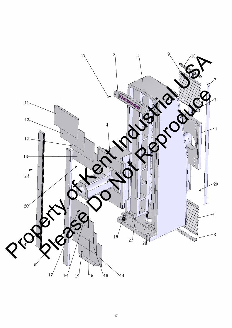
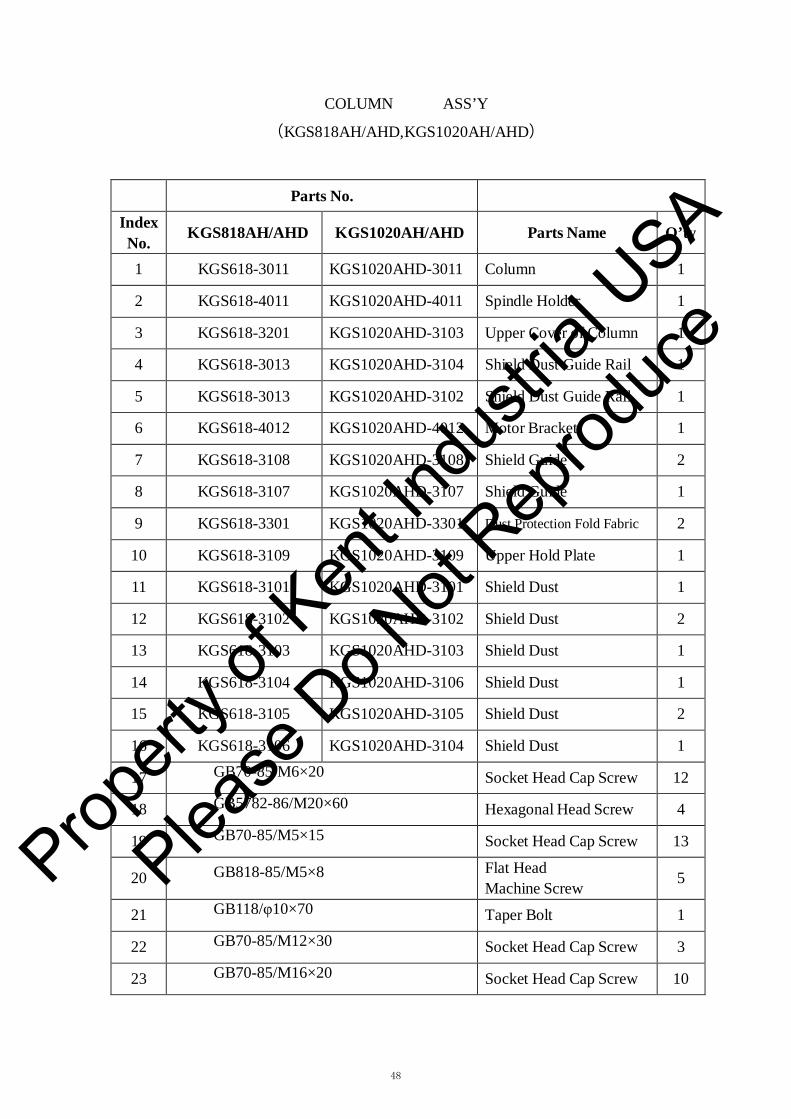
COLUMN ASS’Y
(KGS818AH/AHD,KGS1020AH/AHD)
Parts No.
Index No. KGS818AH/AHD KGS1020AH/AHD Parts Name Q’ty
1 KGS618-3011 KGS1020AHD-3011 Column 1
2 KGS618-4011 KGS1020AHD-4011 Spindle Holder 1
3 KGS618-3201 KGS1020AHD-3103 Upper Cover of Column 1
4 KGS618-3013 KGS1020AHD-3104 Shield Dust Guide Rail 1
5 KGS618-3013 KGS1020AHD-3102 Shield Dust Guide Rail 1
6 KGS618-4012 KGS1020AHD-4012 Motor Bracket 1
7 KGS618-3108 KGS1020AHD-3108 Shield Guide 2
8 KGS618-3107 KGS1020AHD-3107 Shield Guide 1
9 KGS618-3301 KGS1020AHD-3301 Dust Protection Fold Fabric 2
10 KGS618-3109 KGS1020AHD-3109 Upper Hold Plate 1
11 KGS618-3101 KGS1020AHD-3101 Shield Dust 1
12 KGS618-3102 KGS1020AHD-3102 Shield Dust 2
13 KGS618-3103 KGS1020AHD-3103 Shield Dust 1
14 KGS618-3104 KGS1020AHD-3106 Shield Dust 1
15 KGS618-3105 KGS1020AHD-3105 Shield Dust 2
16 KGS618-3106 KGS1020AHD-3104 Shield Dust 1
17 GB70-85/M6×20 Socket Head Cap Screw 12
18 GB5782-86/M20×60 Hexagonal Head Screw 4
19 GB70-85/M5×15 Socket Head Cap Screw 13
20 GB818-85/M5×8 Flat Head Machine Screw 5
21 GB118/φ10×70 Taper Bolt 1
22 GB70-85/M12×30 Socket Head Cap Screw 3
23 GB70-85/M16×20 Socket Head Cap Screw 10
Propert
y of K
ent In
dustr
ial U
SA
Please
Do N
ot Rep
roduc
e

62
17
34
5
433
1
252624
44
41
40
43
42
4522
23
78
60 57
59
69
67
68
6466
62
6165
191618
20
7374
75
55
76
21
711
8
109
1255
15
14
13
77
4523
4044
424126
2422
25
2771
3079
29
31
36324847
34
63
3928
5056
58
4847
54
4738
70
57
46
49
28
50
35
37
51 72
2852
53
48
78
77
80
62
17
34
5
433
1
252624
44
41
40
43
42
4522
23
78
60 57
59
69
67
68
6466
62
6165
191618
20
7374
75
55
76
21
711
8
109
1255
15
14
13
77
4523
4044
424126
2422
25
2771
3079
29
31
36324847
34
63
3928
5056
58
4847
54
4738
70
57
46
49
28
50
35
37
51 72
2852
53
48
78
77
80
49
Propert
y of K
ent In
dustr
ial U
SA
Please
Do N
ot Rep
roduc
e

50
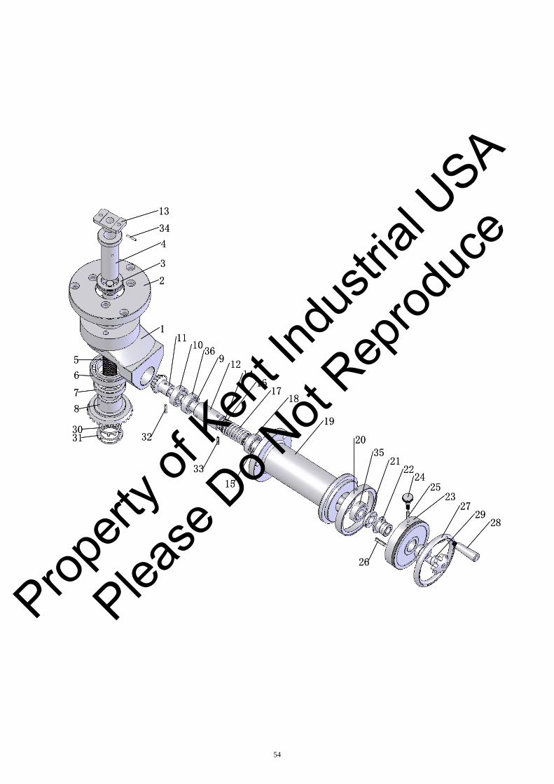
DOWN FEED ASS’Y
(KGS818AHD,KGS1020AHD)
Parts No.
Index No. KGS818AHD KGS1020AHD Parts Name Q’ty
1 KGS1020AHD-1016 Gear Box 1
2 KGS1020AHD-1116 Shaft 2
3 GB894.1-86/25 Snap Ring 1
4 KGS1020AHD-1103 Washer 2
5 KGS1020AHD-1104 Spring 1
6 GB1096-89/6×30 Key 1
7 KGS1020AHD-1117 Clutch 1
8 KGS1020AHD-1137 Clutch 1
9 KGS1020AHD-1136 Gear 1
10 GB70-85/M5×10 Socket Head Cap Screw 4
11 6006-2Z Bearing 1
12 KGS1020AHD-1018 Holder 1
13 KGS1020AHD-1134 Holder 1
14 GB70-85/M6×45 Socket Head Cap Screw 1
15 6204-2Z Bearing 1
16 KGS1020AHD-1129 Nut 1
17 GB1096-89/6×50 Key 1
18 KGS1020AHD-1130 Ring 1
19 KGS1020AHD-1133 Graduation Dial 1
20 KGS1020AHD-1132 Graduation Dial 1
21 KGS1020AHD-1131 Screw 1
22 KGS1020AHD-1159 Flange 2
23 KGS1020AHD-1155 Cylinder 2
24 KGS1020AHD-1158 Half Link 2
Propert
y of K
ent In
dustr
ial U
SA
Please
Do N
ot Rep
roduc
e
51
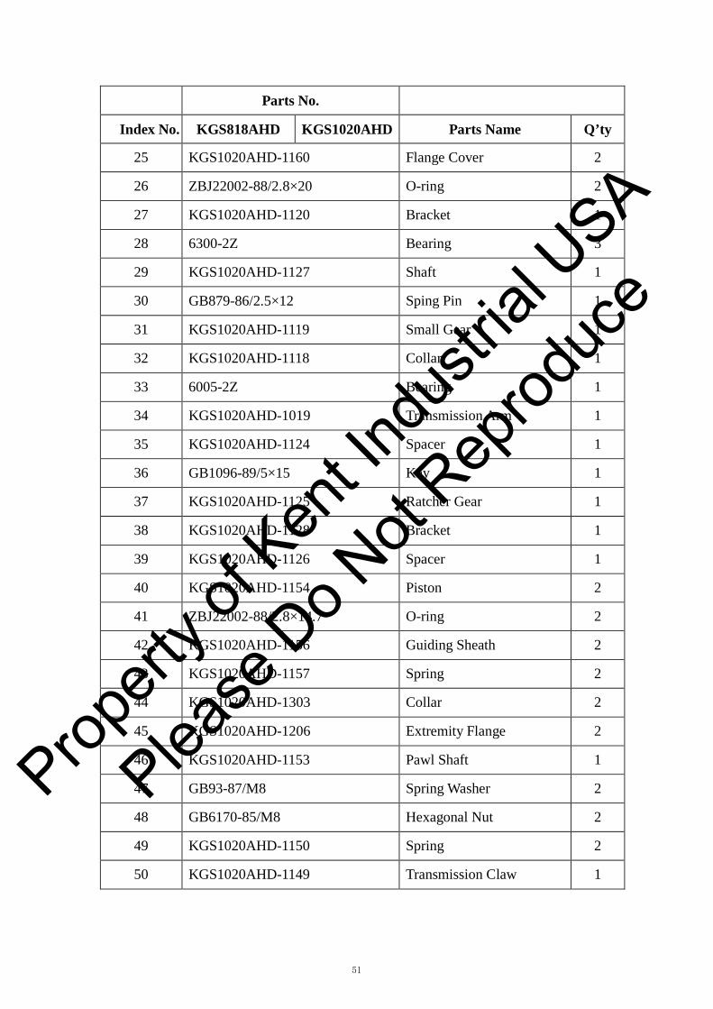
Parts No.
Index No. KGS818AHD KGS1020AHD Parts Name Q’ty
25 KGS1020AHD-1160 Flange Cover 2
26 ZBJ22002-88/2.8×20 O-ring 2
27 KGS1020AHD-1120 Bracket 1
28 6300-2Z Bearing 3
29 KGS1020AHD-1127 Shaft 1
30 GB879-86/2.5×12 Sping Pin 1
31 KGS1020AHD-1119 Small Gear 1
32 KGS1020AHD-1118 Collar 1
33 6005-2Z Bearing 1
34 KGS1020AHD-1019 Transmission Arm 1
35 KGS1020AHD-1124 Spacer 1
36 GB1096-89/5×15 Key 1
37 KGS1020AHD-1125 Ratcher Gear 1
38 KGS1020AHD-1128 Bracket 1
39 KGS1020AHD-1126 Spacer 1
40 KGS1020AHD-1154 Piston 2
41 ZBJ22002-88/2.8×14.7 O-ring 2
42 KGS1020AHD-1156 Guiding Sheath 2
43 KGS1020AHD-1157 Spring 2
44 KGS1020AHD-1303 Collar 2
45 KGS1020AHD-1206 Extremity Flange 2
46 KGS1020AHD-1153 Pawl Shaft 1
47 GB93-87/M8 Spring Washer 2
48 GB6170-85/M8 Hexagonal Nut 2
49 KGS1020AHD-1150 Spring 2
50 KGS1020AHD-1149 Transmission Claw 1
Propert
y of K
ent In
dustr
ial U
SA
Please
Do N
ot Rep
roduc
e
52
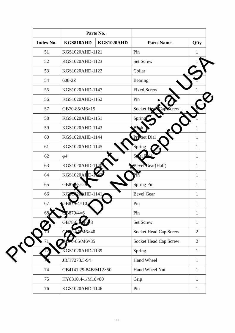
Parts No.
Index No. KGS818AHD KGS1020AHD Parts Name Q’ty
51 KGS1020AHD-1121 Pin 1
52 KGS1020AHD-1123 Set Screw 1
53 KGS1020AHD-1122 Collar 1
54 608-2Z Bearing 1
55 KGS1020AHD-1147 Fixed Screw 1
56 KGS1020AHD-1152 Pin 1
57 GB70-85/M6×15 Socket Head Cap Screw 5
58 KGS1020AHD-1151 Spring 1
59 KGS1020AHD-1143 Bush 1
60 KGS1020AHD-1144 Pre-set Dial 1
61 KGS1020AHD-1145 Spring 1
62 φ4 Steel Ball 1
63 KGS1020AHD-1140 Bevel Gear(Half) 1
64 KGS1020AHD-1142 Pin 1
65 GB879/5×28 Spring Pin 1
66 KGS1020AHD-1141 Bevel Gear 1
67 GB879/4×10 Pin 1
68 GB879/4×6 Pin 1
69 GB78-85/M6×8 Set Screw 1
70 GB70-85/M6×40 Socket Head Cap Screw 2
71 GB70-85/M6×35 Socket Head Cap Screw 2
72 KGS1020AHD-1139 Spring 1
73 JB/T7273.5-94 Hand Wheel 1
74 GB4141.29-84B/M12×50 Hand Wheel Nut 1
75 HY8310.4-1/M10×80 Grip 1
76 KGS1020AHD-1146 Pin 1
Propert
y of K
ent In
dustr
ial U
SA
Please
Do N
ot Rep
roduc
e

53
Parts No.
Index No. KGS818AHD KGS1020AHD Parts Name Q’ty
77 KGS1020AHD-1017 Cover 2
78 GB70-85/M6×20 Socket Head Cap Screw 8
79 6201-2Z Bearing 1
80 GB70-85/M5×20 Socket Head Cap Screw 1
Propert
y of K
ent In
dustr
ial U
SA
Please
Do N
ot Rep
roduc
e
13
4
3
2
34
1
6
7
8
3031
5
1110
912
1614
18
19
2035
2122
2425
2327
2928
32
33
15
17
26
36
13
4
3
2
34
1
6
7
8
3031
5
1110
912
1614
18
19
2035
2122
2425
2327
2928
32
33
15
17
26
36
54
Propert
y of K
ent In
dustr
ial U
SA
Please
Do N
ot Rep
roduc
e
55
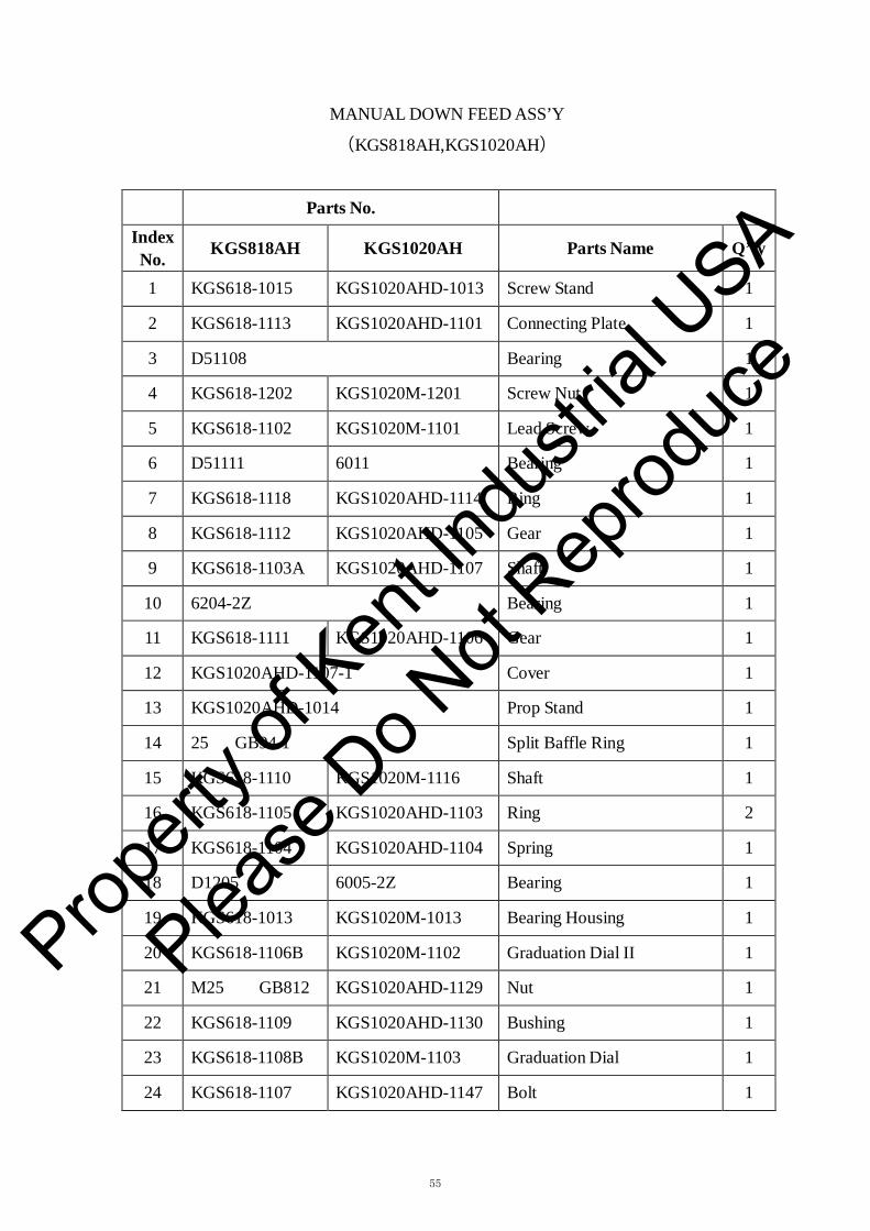
MANUAL DOWN FEED ASS’Y
(KGS818AH,KGS1020AH) Parts No.
Index No.
KGS818AH
KGS1020AH
Parts Name
Q’ty
1 KGS618-1015 KGS1020AHD-1013 Screw Stand 1
2 KGS618-1113 KGS1020AHD-1101 Connecting Plate 1
3 D51108 Bearing 1
4 KGS618-1202 KGS1020M-1201 Screw Nut 1
5 KGS618-1102 KGS1020M-1101 Lead Screw 1
6 D51111 6011 Bearing 1
7 KGS618-1118 KGS1020AHD-1114 Ring 1
8 KGS618-1112 KGS1020AHD-1105 Gear 1
9 KGS618-1103A KGS1020AHD-1107 Shaft 1
10 6204-2Z Bearing 1
11 KGS618-1111 KGS1020AHD-1106 Gear 1
12 KGS1020AHD-1107-1 Cover 1
13 KGS1020AHD-1014 Prop Stand 1
14 25 GB94.1 Split Baffle Ring 1
15 KGS618-1110 KGS1020M-1116 Shaft 1
16 KGS618-1105 KGS1020AHD-1103 Ring 2
17 KGS618-1104 KGS1020AHD-1104 Spring 1
18 D1205 6005-2Z Bearing 1
19 KGS618-1013 KGS1020M-1013 Bearing Housing 1
20 KGS618-1106B KGS1020M-1102 Graduation Dial II 1
21 M25 GB812 KGS1020AHD-1129 Nut 1
22 KGS618-1109 KGS1020AHD-1130 Bushing 1
23 KGS618-1108B KGS1020M-1103 Graduation Dial 1
24 KGS618-1107 KGS1020AHD-1147 Bolt 1
Propert
y of K
ent In
dustr
ial U
SA
Please
Do N
ot Rep
roduc
e
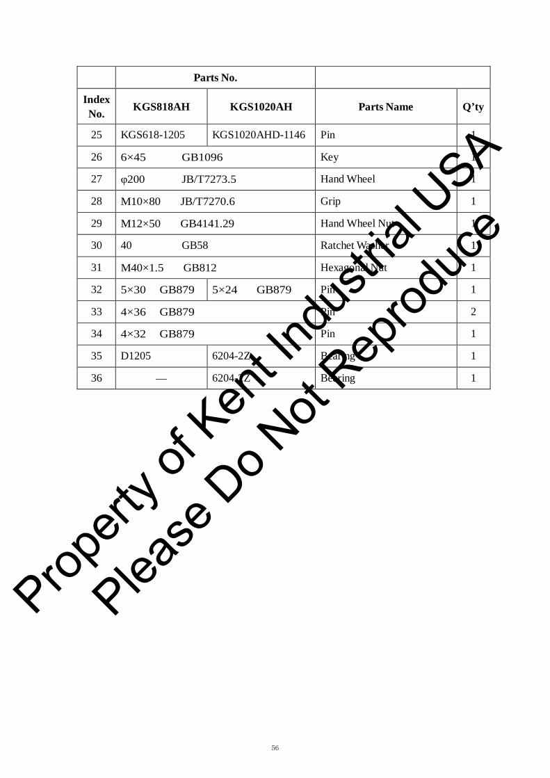
56
Parts No.
Index No.
KGS818AH
KGS1020AH
Parts Name
Q’ty
25 KGS618-1205 KGS1020AHD-1146 Pin 1
26 6×45 GB1096 Key 1
27 φ200 JB/T7273.5 Hand Wheel 1
28 M10×80 JB/T7270.6 Grip 1
29 M12×50 GB4141.29 Hand Wheel Nut 1
30 40 GB58 Ratchet Washer 1
31 M40×1.5 GB812 Hexagonal Nut 1
32 5×30 GB879 5×24 GB879 Pin 1
33 4×36 GB879 Pin 2
34 4×32 GB879 Pin 1
35 D1205 6204-2Z Bearing 1
36 — 6204-2Z Bearing 1
Propert
y of K
ent In
dustr
ial U
SA
Please
Do N
ot Rep
roduc
e

1
2
4
2
6
78
109
8
13
5
8
910
8
11
1514
12
1
2
4
2
6
78
109
8
13
5
8
910
8
11
1514
12
57
Propert
y of K
ent In
dustr
ial U
SA
Please
Do N
ot Rep
roduc
e

58
SPINDLE ASS’Y
(KGS818AH/AHD,KGS1020AH/AHD) Parts No.
Index No.
KGS818AH/AHD
KGS1020AH/AHD
Parts Name
Q’ty
1 YUZC90L-A/B5 Spindle Motor 1
2 KGS1020AHD-4118A Coupling 2
3 GB1096-90/8×25 Key 1
4 KGS1020AHD-4302 Rubber Coupling 1
5 KGS618-4102 KGS1020AHD-4111 Spindle Shaft 1
6 KGS1020AHD-4115 Spindle Cover 1
7 KGS1020AHD-4114 Spindle Cover 1
8 7206 CTYSUL P4 Angular Contact
Bearing
4
9 KGS1020AHD-4109 Spacer 2
10 KGS1020AHD-4110 Spacer 2
11 KGS1020AHD-4103A Spindle Nut 1
12 KGS1020AHD-4102B Spindle Cover 1
13 KGS618-4103 KGS1020AHD-4112A Spindle Housing 1
14 KGS1020AHD-4101B Spindle Cover 1
15 KGS1020AHD-4013A Installation Link 1
Propert
y of K
ent In
dustr
ial U
SA
Please
Do N
ot Rep
roduc
e

25
6
10
1
26
29
30
4
3
2
20
27
21
22
2421
23
5
12
7
14
13
9
8
11
15
1617
28
18
19
25
6
10
1
26
29
30
4
3
2
20
27
21
22
2421
23
5
12
7
14
13
9
8
11
15
1617
28
18
19
59
Propert
y of K
ent In
dustr
ial U
SA
Please
Do N
ot Rep
roduc
e

60
CROSS FEED ASS’Y
(KGS818AH/AHD,KGS1020AH/AHD) Parts No.
Index No.
KGS818AH/AHD
KGS1020AH/AHD
Parts Name
Q’ty
1 KGS818AHD-2107 KGS1020AHD-2105 Cross Feed Leadscrew 1
2 GB1096-79/5×35 Key 1
3 GB1096-79/4×25 Key 1
4 GB1096-79/5×16 Key 1
5 KGS1020AHD-2016 Timing Belt Pulley 1
6 KGS1020AHD-2106 Spacer 1
7 3204-2Z Bearing 1
8 GB812-88/M20×1.5 Hexagonal Nut 2
9 GB858-88/φ20 Ratchet Washer 1
10 KGS1020AHD-2113 Bearing Retainer 1
11 KGS1020AHD-2114 Bush 1
12 KGS1020AHD-2112 Bearing Holder 1
13 GB70-85/M6×16 Socket Head Screw 3
14 GB70-85/M6×30 Socket Head Screw 3
15 KGS1020AHD-2107 Graduation Dial 1
16 KGS1020AHD-2201 Pin 1
17 GB835-88/M6×25 Adjusting Screw 1
18 GB97.2/12 Washer 1
19 GB804/M12 Nut 1
20 JW5626/60W Crossfeed Motor 1
21 GB894.1-86/18 Snap Ring 2
22 KGS1020AHD-2118 Small Timing Belt Pulley 1
23 GB894.1-86/11 Snap Ring 1
Propert
y of K
ent In
dustr
ial U
SA
Please
Do N
ot Rep
roduc
e

61
Parts No.
Index No.
KGS818AH/AHD
KGS1020AH/AHD
Parts Name
Q’ty
24 GB13487-92/187L075 Timing Belt 1
25 KGS1020AHD-1012 Crossfeed Nut Base 1
26 GB70-85/M10×55 Socket Head Screw 4
27 GB70-85/M8×15 Socket Head Screw 4
28 JB/T7273.5/φ200 Hand Wheel 1
29 KGS1020AHD-1207 Leadscrew Backlash Adjust 1
30 GB70-85/M8×20 Socket Head Screw 4
Propert
y of K
ent In
dustr
ial U
SA
Please
Do N
ot Rep
roduc
e

1
9
2
8
435
3
8
1
9
2
8
435
3
8
62
Propert
y of K
ent In
dustr
ial U
SA
Please
Do N
ot Rep
roduc
e

63
CROSSFEED CONTROL LIMIT SWITCH
(KGS818AH/AHD,KGS1020AH/AHD) Parts No.
Index No.
KGS818AH/AHD
KGS1020AH/AHD
Parts Name
Q’ty
1 KGS1020AHD-2127 Dog 1
2 GB70-85/M5×25 Socket Head Screw 2
3 KGS1020AHD-2123 Mounting Bracket 2
4 KGS1020AHD-2124 Pad Rod 1
5 KGS1020AHD-2125 Dog 2
6 GB70-85/M6×50 Socket Head Screw 4
7 GB70-85/M6×8 Socket Head Screw 4
8 ZE-NA2-2 Limit Switch 4
9 KGS1020AHD-2126 Dog 1
Propert
y of K
ent In
dustr
ial U
SA
Please
Do N
ot Rep
roduc
e

215
14
13
12
10
11
8
9
16
17
7
6
5
18
18
4
9
10
15
1
2
3
215
14
13
12
10
11
8
9
16
17
7
6
5
18
18
4
9
10
15
1
2
3
64
Propert
y of K
ent In
dustr
ial U
SA
Please
Do N
ot Rep
roduc
e

65
CYLINDER
(KGS818AH/AHD,KGS1020AH/AHD)
Parts No.
Index No.
KGS818AH/AHD
KGS1020AH/AHD
Parts Name
Q’ty
1 KGS818AHD-7101 KGS1020AHD-7115 Piston Rod 1
2 GB6170/M8 Nut 4
3 KGS818AHD-7101 KGS1020AHD-7111 Piston Rod A 1
4 KGS818AHD-7012 KGS1020AHD-7012 Piston 1
5 — 1.8×φ15.8 O-Ring 1
6 KGS1020AHD-7308 Wear-resisting Ring 1
7 KGS818AHD-7102 KGS1020AHD-7113 Cylinder 1
8 KGS1020AHD-7114 Tight Ring 2
9 KGS1020AHD-7112 Cylinder Clamper 2
10 KGS818AHD-7011 KGS1020AHD-7011 End Cover 2
11 3.1×φ30 O-Ring 2
12 USH-20CU0212K0 Dust Seal 2
13 KGS1020AHD-7201 Sustaining Sheath 2
14 LSH-20 CL0017C0 Dust Seal 2
15 KGS1020AHD-7116 Cylinder Bracket 2
16 GB97.2/φ8 Washer 8
17 GB70/M8×55 Socket Head Screw 8
18 USH-22.4CU0260K0 Dust Seal 2
Propert
y of K
ent In
dustr
ial U
SA
Please
Do N
ot Rep
roduc
e

10
89
6
11
12
54 6
7
6
1
2
13
3
10
89
6
11
12
54 6
7
6
1
2
13
3
66
Propert
y of K
ent In
dustr
ial U
SA
Please
Do N
ot Rep
roduc
e

67
VALVE
(KGS1020AH/AHD)
Index
No.
Parts No.
Parts Name
Q’ty KGS1020AH/AHD
1. 3K25 Flow Control Valve 1
2. KGS1020AHD-2117 Limit Switch Mounting Bracket 1
3. KGS1020AHD-2116 Cam 1
4. KGS1020AHD-2110A Flow Control Knob 1
5. KGS1020AHD-2111 Flow Control Lever 1
6. M8×30 Socket Head Cap Screw 1
7. KGS1020AHD-2015 Direction Control Arm 1
8. KGS1020AHD-2018 Dog 1
9. KGS1020AHD-2108 Nut 2
10. KGS1020AHD-2017 Dog 1
11. KGS1020AHD-2109 Small Shaft 2
12. 627-2Z Bearing 4
13. ZE-NA-2 Limit Switch 2
Propert
y of K
ent In
dustr
ial U
SA
Please
Do N
ot Rep
roduc
e
2
23
29
7
6
5
10
34
24 4
3
11
262825
32
14
15
38
35
1618 1719
25
21
2027
12
22
31
8
33
13
9
37
36
1
39
4041
4230
2
23
29
7
6
5
10
34
24 4
3
11
262825
32
14
15
38
35
1618 1719
25
21
2027
12
22
31
8
33
13
9
37
36
1
39
4041
4230
68
Propert
y of K
ent In
dustr
ial U
SA
Please
Do N
ot Rep
roduc
e
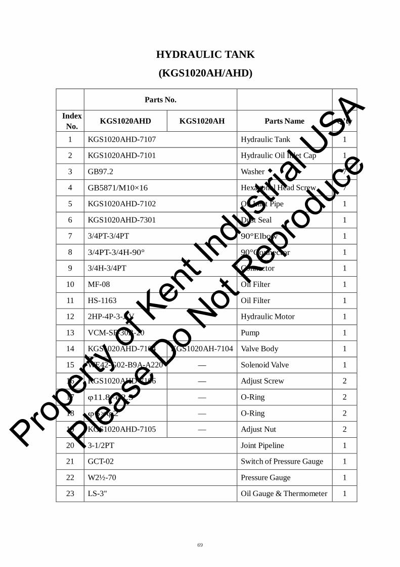
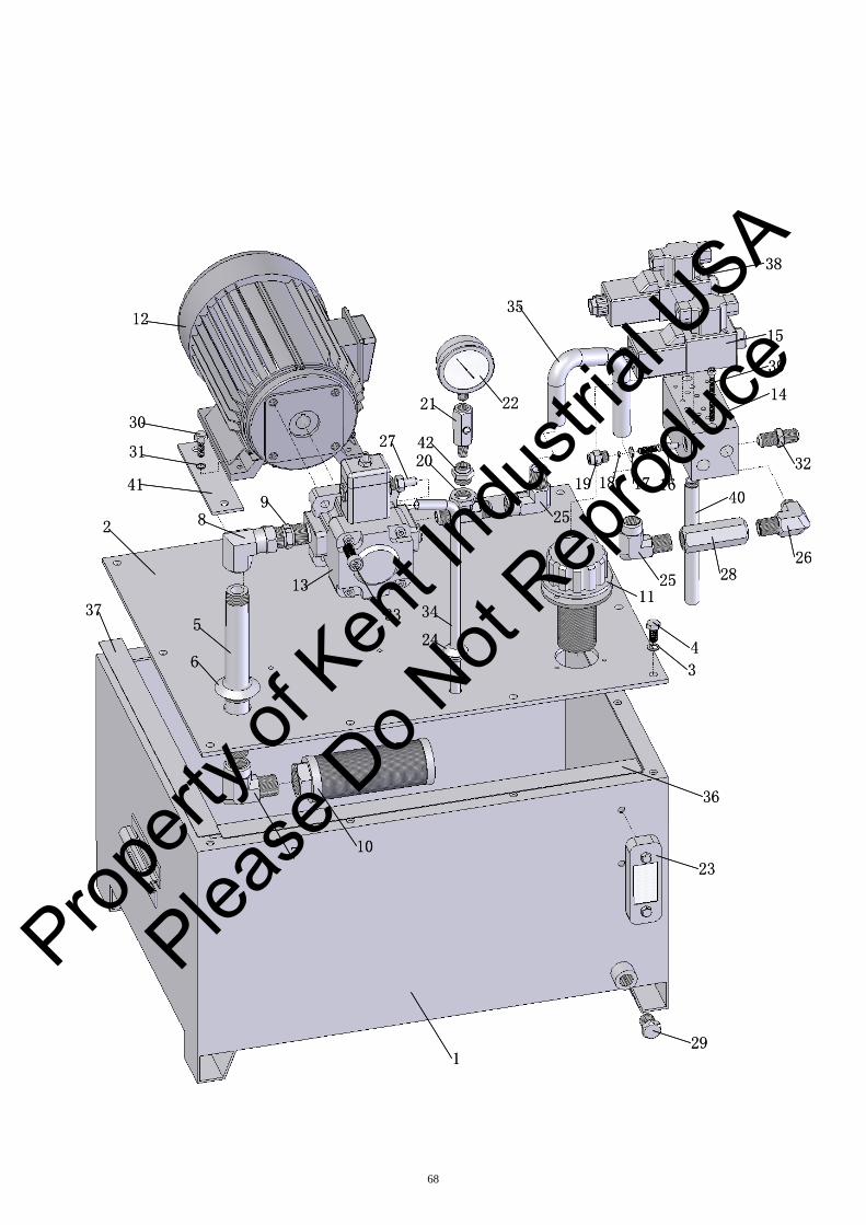
69
HYDRAULIC TANK
(KGS1020AH/AHD)
Parts No.
Index No.
KGS1020AHD
KGS1020AH
Parts Name
Q’ty
1 KGS1020AHD-7107 Hydraulic Tank 1
2 KGS1020AHD-7101 Hydraulic Oil Inlet Cap 1
3 GB97.2 Washer 7
4 GB5871/M10×16 Hexagonal Head Screw 7
5 KGS1020AHD-7102 Oil Inlet Pipe 1
6 KGS1020AHD-7301 Dust Seal 1
7 3/4PT-3/4PT 90°Elbow 1
8 3/4PT-3/4H-90° 90°Connector 1
9 3/4H-3/4PT Connector 1
10 MF-08 Oil Filter 1
11 HS-1163 Oil Filter 1
12 2HP-4P-3-J-V Hydraulic Motor 1
13 VCM-SF-30B-20 Pump 1
14 KGS1020AHD-7104 KGS1020AH-7104 Valve Body 1
15 WE42-G02-B9A-A220 — Solenoid Valve 1
16 KGS1020AHD-7106 — Adjust Screw 2
17 φ11.8×φ2.5 — O-Ring 2
18 φ6×φ2 — O-Ring 2
19 KGS1020AHD-7105 — Adjust Nut 2
20 3-1/2PT Joint Pipeline 1
21 GCT-02 Switch of Pressure Gauge 1
22 W2½-70 Pressure Gauge 1
23 LS-3" Oil Gauge & Thermometer 1
Propert
y of K
ent In
dustr
ial U
SA
Please
Do N
ot Rep
roduc
e

70
Parts No.
Index No.
KGS1020AHD
KGS1020AH
Parts Name
Q’ty
24 KGS1020AHD-7302 Dust Seal 1
25 1/2PT-1/4PT 90°Connector 1
26 1/2PT-3/8PT 90°Connector 1
27 1/4PT-φ10 Joint Pipeline 1
28 CIT-04 1/2PT Sequence Valve 1
29 Z1/2 Plug 1
30 GB5781/M8×25 Hexagonal Head Screw 4
31 GB97.2/φ8 Washer 4
32 3/8H-3/8PT Connector 4
33 GB70-85 Socket Head Screw 4
34 φ10 Copper Pipe 1
35 1/2H L=440mm Nylon Tube 1
36 KGS1020AHD-7304 Rubber Gasket 2
37 KGS1020AHD-7305 Rubber Gasket 2
38 WE42-G02-B2-A220 — Solenoid Valve 1
39 GB70-85/M6×70 Socket Head Screw 2
40 KGS1020AHD-7103 Oil Return Pipe 1
41 KGS1020AHD-7303 Rubber Gasket 1
42 R1/2"×14-Rc1/4"×19 90°Connector 1
Propert
y of K
ent In
dustr
ial U
SA
Please
Do N
ot Rep
roduc
e

2
22
28
7
6
5
10
33
23 43
11
25
2724
31
34
24
20
19
26
12
21
30
8
32
13
9
16 17
36
35
1
37
40
41
43
47
43
42
45
14
441518
29
46
38
39
2
22
28
7
6
5
10
33
23 43
11
25
2724
31
34
24
20
19
26
12
21
30
8
32
13
9
16 17
36
35
1
37
40
41
43
47
43
42
45
14
441518
29
46
38
39
71
Propert
y of K
ent In
dustr
ial U
SA
Please
Do N
ot Rep
roduc
e
72
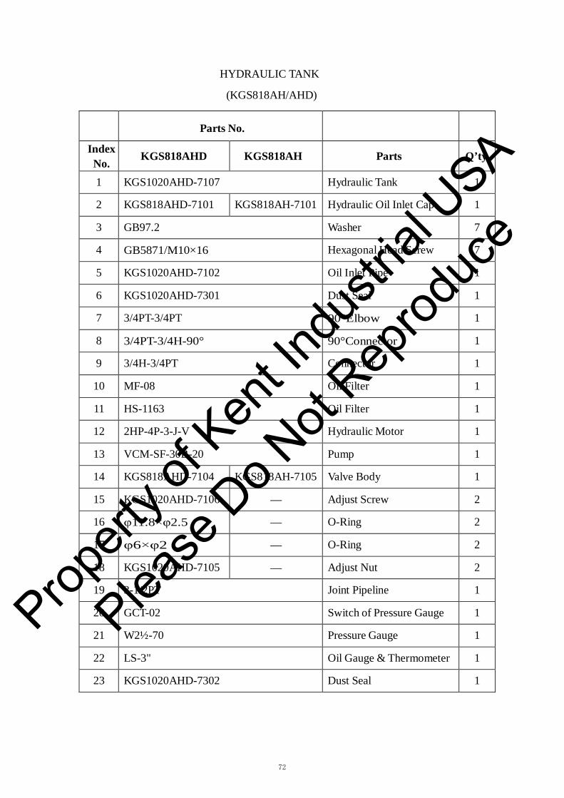
HYDRAULIC TANK
(KGS818AH/AHD)
Parts No.
Index No.
KGS818AHD
KGS818AH
Parts
Q’ty
1 KGS1020AHD-7107 Hydraulic Tank 1
2 KGS818AHD-7101 KGS818AH-7101 Hydraulic Oil Inlet Cap 1
3 GB97.2 Washer 7
4 GB5871/M10×16 Hexagonal Head Screw 7
5 KGS1020AHD-7102 Oil Inlet Pipe 1
6 KGS1020AHD-7301 Dust Seal 1
7 3/4PT-3/4PT 90°Elbow 1
8 3/4PT-3/4H-90° 90°Connector 1
9 3/4H-3/4PT Connector 1
10 MF-08 Oil Filter 1
11 HS-1163 Oil Filter 1
12 2HP-4P-3-J-V Hydraulic Motor 1
13 VCM-SF-30B-20 Pump 1
14 KGS818AHD-7104 KGS818AH-7105 Valve Body 1
15 KGS1020AHD-7106 — Adjust Screw 2
16 φ11.8×φ2.5 — O-Ring 2
17 φ6×φ2 — O-Ring 2
18 KGS1020AHD-7105 — Adjust Nut 2
19 3-1/2PT Joint Pipeline 1
20 GCT-02 Switch of Pressure Gauge 1
21 W2½-70 Pressure Gauge 1
22 LS-3" Oil Gauge & Thermometer 1
23 KGS1020AHD-7302 Dust Seal 1
Propert
y of K
ent In
dustr
ial U
SA
Please
Do N
ot Rep
roduc
e

73
Parts No.
Index No.
KGS818AHD
KGS818AH
Parts
Q’ty
24 1/2PT-1/4PT 90°Connector 2
25 1/2PT-3/8PT 90°Connector 1
26 1/4PT-φ10 Joint Pipeline 1
27 CIT-04 1/2PT Sequence Valve 1
28 Z1/2 Plug 1
29 GB5781/M8×25 Hexagonal Head Screw 4
30 GB97.2/φ8 Washer 4
31 3/8H-3/8PT Connector 4
32 GB70-85 Socket Head Screw 4
33 φ10 Copper Pipe 1
34 1/2H L=440mm Nylon Tube 1
35 KGS1020AHD-7304 Rubber Gasket 2
36 KGS1020AHD-7305 Rubber Gasket 2
37 GB70-85/M6×50 Socket Head Screw 6
38 WE42-G02-B9A-DC24 — Solenoid Valve 1
39 WE42-G02-B2-DC24 — Solenoid Valve 1
40 KGS1020AHD-7103 Oil Return Pipe 1
41 KGS1020AHD-7303 Rubber Gasket 1
42 WE43-G02-C4-DC24 Solenoid Valve 1
43 SOL-04 Direction Control Valve 1
44 GB6176/M8×1 — Nut 2
45 3/8PT-3/8PT-90° — 90°Connector 2
46 Z1/4 Plug 1
47 KGS818AHD-7102 — Oil Return Pipe 1
Propert
y of K
ent In
dustr
ial U
SA
Please
Do N
ot Rep
roduc
e
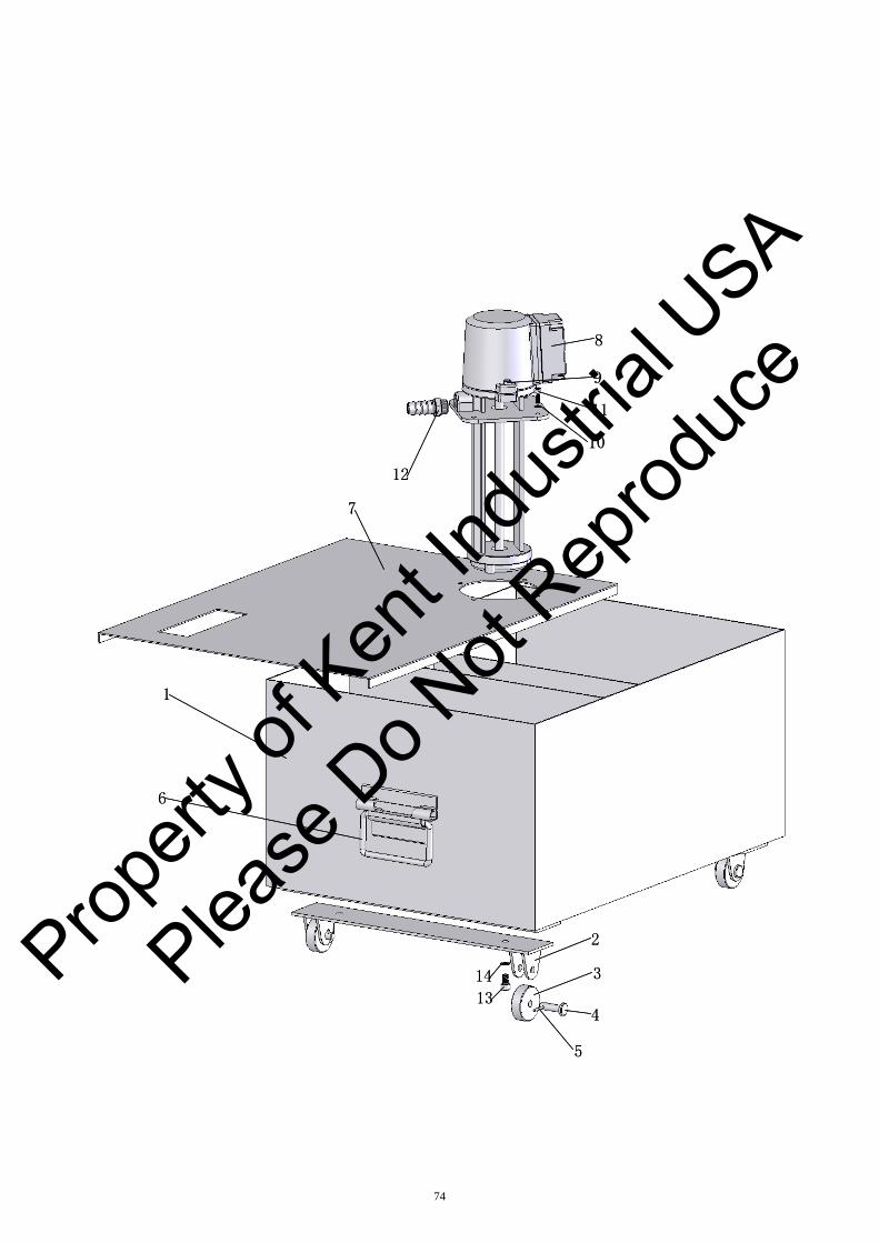
8
11
10
12
7
1
2
3
4
5
9
14
13
6
8
11
10
12
7
1
2
3
4
5
9
14
13
6
74
Propert
y of K
ent In
dustr
ial U
SA
Please
Do N
ot Rep
roduc
e

75
COOLANT SYSTEM
(KGS818AH/AHD,KGS1020AH/AHD)
Parts No.
Index No.
KGS818AH/AHD
KGS1020AH/AHD
Parts Name
Q’ty
1 KGS618-5101 KGS1020AHD-5101 Coolant Tank 1
2 — KGS1020AHD-5101/3 Support Coolant Tank 2
3 — KGS1020AHD-5101/5 Wheel 4
4 — KGS1020AHD-5101/4 Shaft 4
5 — GB91-86 Pin 4
6 KGS618-5101/1 KGS1020AHD-5101/2 Handle 2
7 KGS618-5102 KGS1020AHD-5102A Coolant Tank Cover 1
8 AB-25TH90W Coolant Pump 1
9 GB6170/M6×25 Socket Head Screw 4
10 GB93-86/φ6 Washer 4
11 GB70-85/M6×14 Socket Head Screw 4
12 G72-1/ G1/2 Connector 1
13 — GB70-85/M8×14 Socket Head Screw 4
14 — GB93-86/φ8 Washer 4
Propert
y of K
ent In
dustr
ial U
SA
Please
Do N
ot Rep
roduc
e