instruction and owners manual - oceanbreezeac.com · sure all living spaces are carefully sealed...
TRANSCRIPT
Instruction and Owners Manual
For Self Contained Marine Air Conditioning Units
Manufactured by Quorum Marine and Electronics, Inc.Stuart, Florida
1305 SE Dixie Highway, Stuart, Florida 34994Tel: 1 866 227 7773 (772) 220 0038 email: [email protected]
http://www.oceanbreezeac.com
Table of Contents
Page 2 - Safety Notice (please read carefully)
Page 3 - Basic Air Conditioning Cycle
Page 4 - Major Parts of the Air Conditioning System
Page 5 - Unpacking your AC unit
Page 6 - Selecting Component Location
Page 9 - Installing Through Hull and Seacock
Page 10 - Installing Pump, Strainer, Supply Grills, Ducting
Page 11 - Installing Overboard, Discharge, Condensate
Page 12 - Installing AC Unit and Control
Page 13 - Installing Electric & Control
Page 14 - Diagrams
Page 18 - Warranty Information
IntroductionImportant Safety Notice - Please Read Carefully
Proper installation is critical to the safe, reliable performance of Ocean Breeze Systems Air Conditioners. The procedures recommenended by Ocean Breeze Systems and described in this manual are designed asgeneral guidelines for the successful installation of you unit. Ocean Breeze Systems assumes no liability for the safety of the installer or damage to vessel or other equipment. It is recommended that you consult a qualified electrician or marine repair facility if you have any questions or concerns about proper installation.
It is important to note that this manual contains various CAUTIONS and NOTICES which should be read carefully and adhered to in order to minimize risk of personal injury and reduce the possibility that improper methods may be used which may damage the unit or render it unsafe.
WARNING!
DANGERHigh Voltage
WARNING
Ventilation of Lethal Gases and FumesOcean Breeze Systems units operate on voltagesranging from 115v to 440v AC Power. Because of the danger involved with these voltages, all metalcomponents (bases, cabinets, units) must be grounded to the shipʼs grounding system (see installation notes).Some of the blowers, relays, switches, and thermostats used are not ignition proof. All electrical connections must be sealed or covered in such a way as to prevent contact by unauthorized personnel, as such, contact can lead to permanent injury or death.
To cool or heat air, Ocean Breeze units move air through an evaporator by means of a blower system. Systems must be installed so that they do not cause suction in an area such as the bilge or engine room, where vapors from batteries, fuel, and operating equipment (power generators, etc.) exist, as vapors could be discharged into a living space.Because the unit continually recirculates cabin air, it is recommended that a carbon monoxidedetector be installed in the cabin as an addedmesaure of safety.The best way to prevent the introduction ofdangerous gasses into a living space is to make sure all living spaces are carefully sealed off from all other spaces. However, it is never advisable to completely seal an area without some sort of auxiliary ventilation in the event lethal gasses or fumes form.
DANGER
This Air Conditioner is not Ignition ProtectedDo not install this unit or any component of it (except the pump which is ignition protected) in any space that has gas engines, fuel tanks or fuel line fittings, due to the risk of explosion, injury, and / or property damage.(Ref 33 CFR 183.410).
Ocean Breeze air conditioniners use R410A, R417A, or NU22 refrigerant.These are safer for the environment and work at lower pressure and temperature extremes than the R - 12refrigerant found in automotive and home systems. To minimize the risk of injury when servicing anypressurized refrigerant system, the following precautions should be taken:- Do not release refrigerant into the atmosphere. Refer service to a qualified technician.- Wear eye protection, gloves, long-sleeved clothing. Extensive frost burns can occur if you come into contact with liquid refrigerant. In the event of contact, immediately wash affected area with water and contact a physician.- Never use an open flame to test for refrigerant leaks, refrigerant will break down into toxic gas.
2
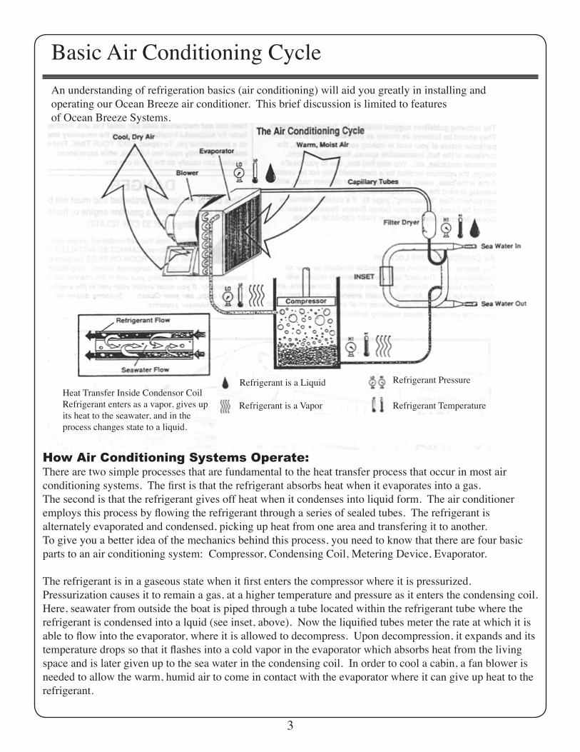
Basic Air Conditioning CycleAn understanding of refrigeration basics (air conditioning) will aid you greatly in installing andoperating our Ocean Breeze air conditioner. This brief discussion is limited to featuresof Ocean Breeze Systems.
Heat Transfer Inside Condensor CoilRefrigerant enters as a vapor, gives upits heat to the seawater, and in theprocess changes state to a liquid.
How Air Conditioning Systems Operate:There are two simple processes that are fundamental to the heat transfer process that occur in most airconditioning systems. The first is that the refrigerant absorbs heat when it evaporates into a gas.The second is that the refrigerant gives off heat when it condenses into liquid form. The air conditioneremploys this process by flowing the refrigerant through a series of sealed tubes. The refrigerant isalternately evaporated and condensed, picking up heat from one area and transfering it to another.To give you a better idea of the mechanics behind this process, you need to know that there are four basic parts to an air conditioning system: Compressor, Condensing Coil, Metering Device, Evaporator.
The refrigerant is in a gaseous state when it first enters the compressor where it is pressurized.Pressurization causes it to remain a gas, at a higher temperature and pressure as it enters the condensing coil. Here, seawater from outside the boat is piped through a tube located within the refrigerant tube where the refrigerant is condensed into a lquid (see inset, above). Now the liquified tubes meter the rate at which it is able to flow into the evaporator, where it is allowed to decompress. Upon decompression, it expands and its temperature drops so that it flashes into a cold vapor in the evaporator which absorbs heat from the living space and is later given up to the sea water in the condensing coil. In order to cool a cabin, a fan blower is needed to allow the warm, humid air to come in contact with the evaporator where it can give up heat to the refrigerant.
3
Refrigerant is a Liquid
Refrigerant is a Vapor
Refrigerant Pressure
Refrigerant Temperature
Major Parts of the Air Condition System
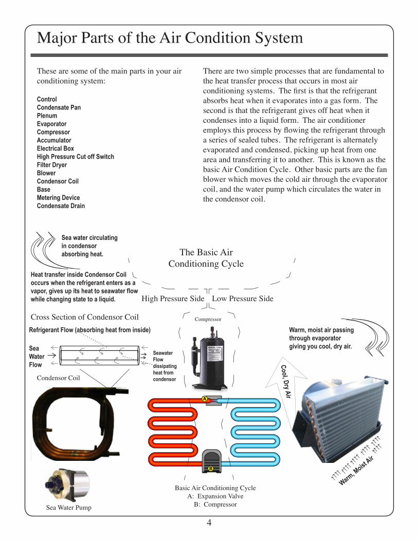
These are some of the main parts in your airconditioning system:
ControlCondensate PanPlenumEvaporatorCompressorAccumulatorElectrical BoxHigh Pressure Cut off SwitchFilter DryerBlowerCondensor CoilBaseMetering DeviceCondensate Drain
Basic Air Conditioning CycleA: Expansion Valve
B: Compressor
Compressor
Condensor Coil
Sea Water Pump
Sea water circulatingin condensorabsorbing heat.
Warm, moist air passingthrough evaporatorgiving you cool, dry air.
High Pressure Side Low Pressure Side
Refrigerant Flow (absorbing heat from inside)
Seawater Flowdissipating heat from condensor
SeaWater Flow
Cross Section of Condensor Coil
Heat transfer inside Condensor Coil occurs when the refrigerant enters as a vapor, gives up its heat to seawater flow while changing state to a liquid.
Warm, M
oist Air
Cool, D
ry Air
There are two simple processes that are fundamental to the heat transfer process that occurs in most airconditioning systems. The first is that the refrigerant absorbs heat when it evaporates into a gas form. The second is that the refrigerant gives off heat when itcondenses into a liquid form. The air conditioner employs this process by flowing the refrigerant through a series of sealed tubes. The refrigerant is alternately evaporated and condensed, picking up heat from one area and transferring it to another. This is known as the basic Air Condition Cycle. Other basic parts are the fan blower which moves the cold air through the evaporator coil, and the water pump which circulates the water in the condensor coil.
The Basic AirConditioning Cycle
4
Unpacking your AC unit
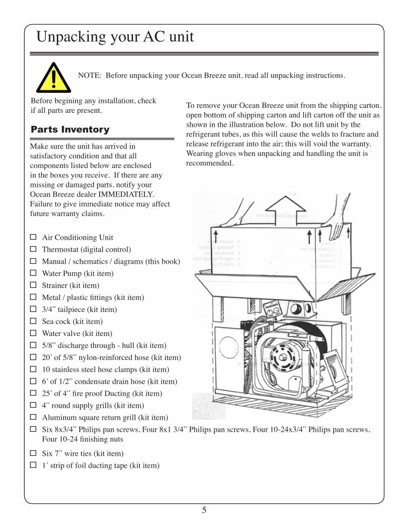
NOTE: Before unpacking your Ocean Breeze unit, read all unpacking instructions.
To remove your Ocean Breeze unit from the shipping carton, open bottom of shipping carton and lift carton off the unit as shown in the illustration below. Do not lift unit by therefrigerant tubes, as this will cause the welds to fracture andrelease refrigerant into the air; this will void the warranty. Wearing gloves when unpacking and handling the unit isrecommended.
Before begining any installation, check if all parts are present.
Parts Inventory
Make sure the unit has arrived insatisfactory condition and that allcomponents listed below are enclosedin the boxes you receive. If there are anymissing or damaged parts, notify yourOcean Breeze dealer IMMEDIATELY.Failure to give immediate notice may affectfuture warranty claims.
Air Conditioning Unit
Water Pump (kit item)
Thermostat (digital control)
3/4” tailpiece (kit item)
20 ̓of 5/8” nylon-reinforced hose (kit item)10 stainless steel hose clamps (kit item)
5/8” discharge through - hull (kit item)
6 ̓of 1/2” condensate drain hose (kit item)25 ̓of 4” fire proof Ducting (kit item)
Sea cock (kit item)Water valve (kit item)
Strainer (kit item)Metal / plastic fittings (kit item)
4” round supply grills (kit item)Aluminum square return grill (kit item)Six 8x3/4” Philips pan screws, Four 8x1 3/4” Philips pan screws, Four 10-24x3/4” Philips pan screws,Four 10-24 finishing nuts
Manual / schematics / diagrams (this book)
Six 7” wire ties (kit item)1 ̓strip of foil ducting tape (kit item)
5
Selecting Component LocationsYou will need to find locations for all of the following components. They should be followed as closely aspossible. Keep in mind the particular nature of your boat in making your selections, i.e., the curvature of the hull,inaccessable spaces, foam-filled spaces, structuralobstacles, etc. You may find that, due to your boatʼs design, the optimum location for a component may not be useable. If this is the case, select an alternate spot ordifferent route, while keeping in mind the spacerequirements and limitations for that component. If a suitable alternative location cannot be found, contact your Ocean Breeze dealer or Ocean Breeze AC directly at772 220 0038 for assistance.
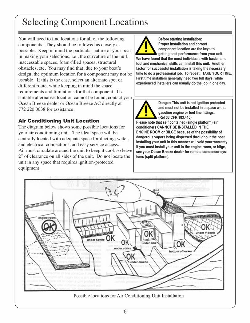
Air Conditioning Unit LocationThe diagram below shows some possible locations for your air conditioning unit. The ideal space will becentrally located with adequate space for ducting, water, and electrical connections, and easy service access.Air must circulate around the unit to keep it cool, so leave 2” of clearance on all sides of the unit. Do not locate the unit in any space that requires ignition-protectedequipment.
Before starting installation: Proper installation and correct component location are the keys to getting best performance from your unit.We have found that the most individuals with basic hand tool and mechanical skills can install this unit. Anotherfactor for successful installation is taking the necessary time to do a professional job. To repeat: TAKE YOUR TIME. First time installers generally need two full days, whileexperienced installers can usually do the job in one day.
Danger: This unit is not ignition protected and must not be installed in a space with a gasoline engine or fuel line fittings. (Ref 33 CFR 183.410)Please note that self contained (single platform) airconditioners CANNOT BE INSTALLED IN THEENGINE ROOM or BILGE because of the possibility ofdangerous vapors being dispersed throughout the boat.Installing your unit in this manner will void your warranty.If you must install your unit in the engine room, or bilge,see your Ocean Breeze dealer for remote condensor sys-tems (split platform).
Possible locations for Air Conditioning Unit Installation
6
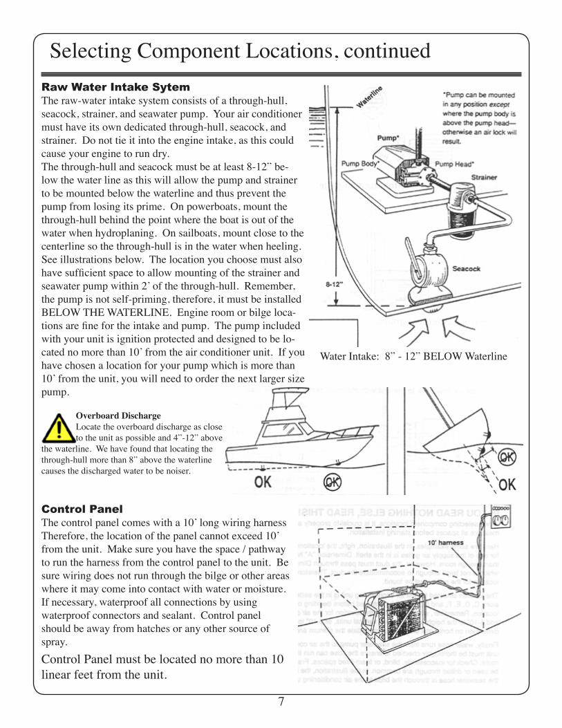
Selecting Component Locations, continuedRaw Water Intake SytemThe raw-water intake system consists of a through-hull,seacock, strainer, and seawater pump. Your air conditioner must have its own dedicated through-hull, seacock, and strainer. Do not tie it into the engine intake, as this could cause your engine to run dry.The through-hull and seacock must be at least 8-12” be-low the water line as this will allow the pump and strainer to be mounted below the waterline and thus prevent the pump from losing its prime. On powerboats, mount the through-hull behind the point where the boat is out of the water when hydroplaning. On sailboats, mount close to the centerline so the through-hull is in the water when heeling. See illustrations below. The location you choose must also have sufficient space to allow mounting of the strainer and seawater pump within 2 ̓of the through-hull. Remember, the pump is not self-priming, therefore, it must be installed BELOW THE WATERLINE. Engine room or bilge loca-tions are fine for the intake and pump. The pump included with your unit is ignition protected and designed to be lo-cated no more than 10 ̓from the air conditioner unit. If you have chosen a location for your pump which is more than 10 ̓from the unit, you will need to order the next larger size pump.
Water Intake: 8” - 12” BELOW Waterline
Overboard Discharge Locate the overboard discharge as close to the unit as possible and 4”-12” above the waterline. We have found that locating the through-hull more than 8” above the waterline causes the discharged water to be noiser.
Control PanelThe control panel comes with a 10 ̓long wiring harnessTherefore, the location of the panel cannot exceed 10ʼfrom the unit. Make sure you have the space / pathway to run the harness from the control panel to the unit. Be sure wiring does not run through the bilge or other areas where it may come into contact with water or moisture.If necessary, waterproof all connections by usingwaterproof connectors and sealant. Control panel should be away from hatches or any other source of spray.Control Panel must be located no more than 10 linear feet from the unit.
7
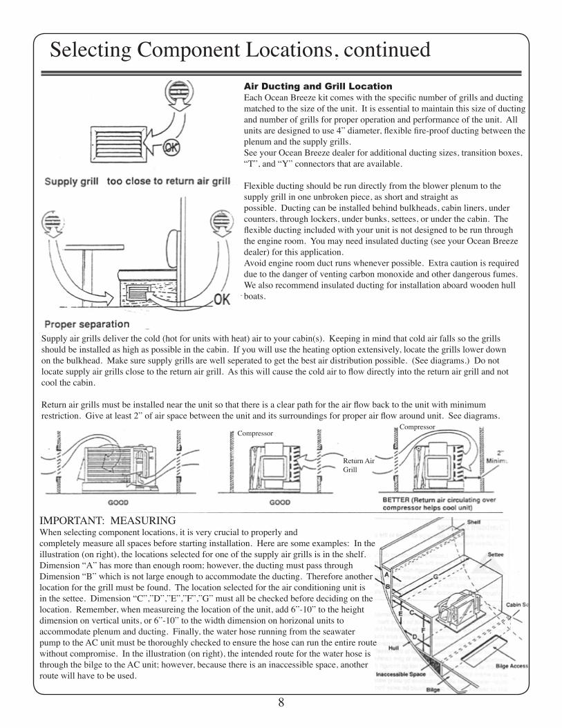
Selecting Component Locations, continuedAir Ducting and Grill LocationEach Ocean Breeze kit comes with the specific number of grills and ducting matched to the size of the unit. It is essential to maintain this size of ducting and number of grills for proper operation and performance of the unit. All units are designed to use 4” diameter, flexible fire-proof ducting between the plenum and the supply grills.See your Ocean Breeze dealer for additional ducting sizes, transition boxes, “T”, and “Y” connectors that are available.
Flexible ducting should be run directly from the blower plenum to thesupply grill in one unbroken piece, as short and straight aspossible. Ducting can be installed behind bulkheads, cabin liners, under counters, through lockers, under bunks, settees, or under the cabin. The flexible ducting included with your unit is not designed to be run through the engine room. You may need insulated ducting (see your Ocean Breeze dealer) for this application.Avoid engine room duct runs whenever possible. Extra caution is required due to the danger of venting carbon monoxide and other dangerous fumes. We also recommend insulated ducting for installation aboard wooden hull boats.
Supply air grills deliver the cold (hot for units with heat) air to your cabin(s). Keeping in mind that cold air falls so the grills should be installed as high as possible in the cabin. If you will use the heating option extensively, locate the grills lower down on the bulkhead. Make sure supply grills are well seperated to get the best air distribution possible. (See diagrams.) Do not locate supply air grills close to the return air grill. As this will cause the cold air to flow directly into the return air grill and not cool the cabin.
Return air grills must be installed near the unit so that there is a clear path for the air flow back to the unit with minimumrestriction. Give at least 2” of air space between the unit and its surroundings for proper air flow around unit. See diagrams.
IMPORTANT: MEASURINGWhen selecting component locations, it is very crucial to properly andcompletely measure all spaces before starting installation. Here are some examples: In the illustration (on right), the locations selected for one of the supply air grills is in the shelf.Dimension “A” has more than enough room; however, the ducting must pass through Dimension “B” which is not large enough to accommodate the ducting. Therefore another location for the grill must be found. The location selected for the air conditioning unit is in the settee. Dimension “C”,”D”,”E”,”F”,”G” must all be checked before deciding on the location. Remember, when measureing the location of the unit, add 6”-10” to the heightdimension on vertical units, or 6”-10” to the width dimension on horizonal units toaccommodate plenum and ducting. Finally, the water hose running from the seawater pump to the AC unit must be thoroughly checked to ensure the hose can run the entire route without compromise. In the illustration (on right), the intended route for the water hose is through the bilge to the AC unit; however, because there is an inaccessible space, another route will have to be used.
8
CompressorCompressor
Return AirGrill

Installation - Through Hull and SeacockParts you will need. Tools you will need.
For the raw-water intake.One 3/4” through-hullOne 3/4” seacockThree 3/4” hose barb tailpiecesOne 3/4” raw-water strainer3/4” nylon-reinforced water hose. (various lengths)Polysulfide or polyurethane sealant.Eight hose clamps (bronze, or marelon)
For 110 VAC electricOne single-pole, single-throw circuit breaker.110 VAC marine-grade, stranded, three-conductor electric wireBoat wire (12 AWG minimum)
To add a second shore-power service30-amp cordset30-amp inletAC electrical panel110 VAC marine-grade stranded, three conductor boat wire (10 AWG minimum)
1/2” reversible power drillHole saw with 7/8”, 1 1/8” & 4 1/2” holes and mandrelsSaber Saw and bladesDrop lightGoggles / eye protectionVice gripsUtility knifeWire crimper / stripper / cutterRulerScrewdrivers (Philips, and straight)Adjustable wrenchesExtension cordFraming squareCaulking gun
Check off each step as it is completed. Then, BEFORE POWERING ON THE UNIT, make sure every step has been checked off.This will help ensure a safe and complete installation.
Before drilling the through-hull hole, CHECK several times for inaccessible spaces, voids, keels, etc. to avoid the time-consuming task of patching unusable holes in the hull. Be sure your hole is far enough from the interior frames and machinery to allow operation of the seacock. Balsa core hulls require professional installation procedures, check with your boat dealer or yard for assistance.
Drill hole through the hull using a 1 1/8” hole sawApply sealant to areas indicated in diagram(DO NOT USE SILICONE SEALANT BELOW THE WATER-LINE)Place backing block on hull (recommended, but not needed, for flush-mount seacocks on flat surfaces).Attach through-hull to seacock. You will also need a flange nut if the through-hull is insulated in the curve of the hull.An in-line seacock should be used in that case (not shown in illustration).Attach tailpiece to seacockCheck to make sure the entire assembly is tight and secure.
9
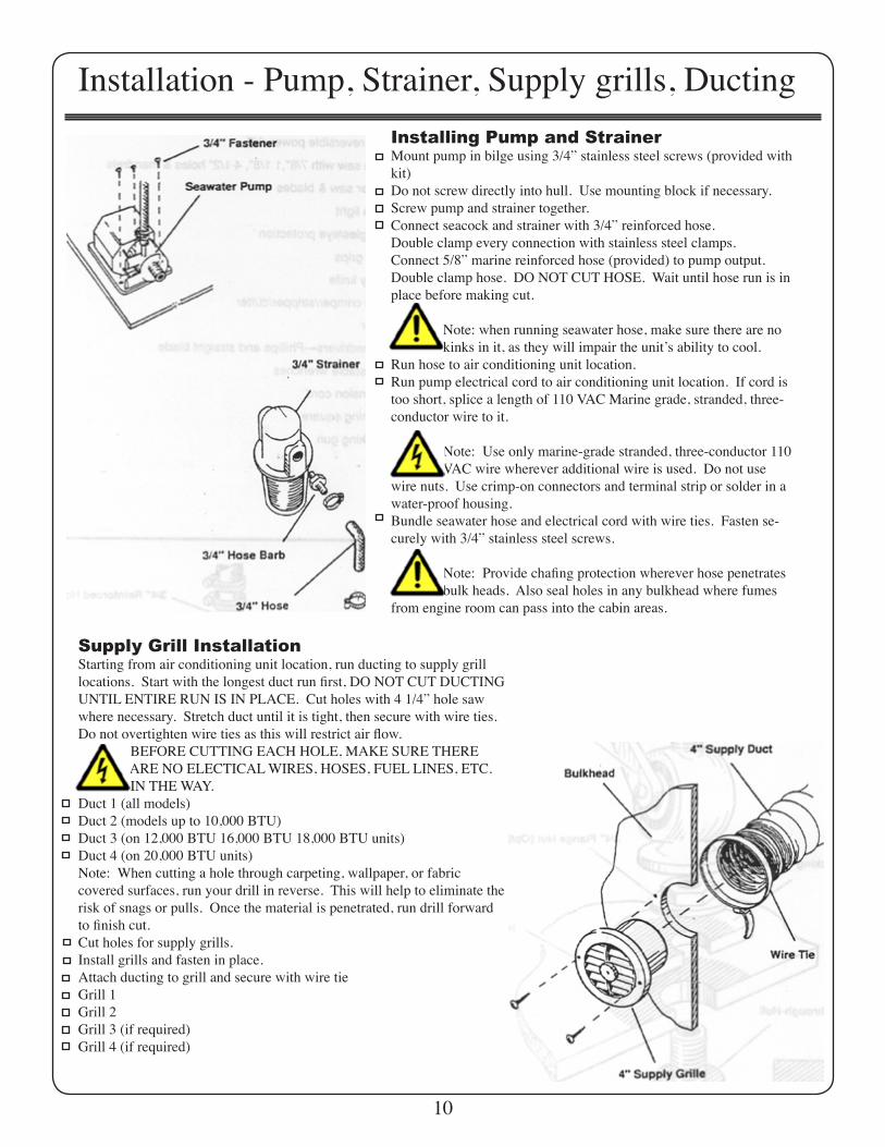
Installation - Pump, Strainer, Supply grills, DuctingInstalling Pump and StrainerMount pump in bilge using 3/4” stainless steel screws (provided with kit)Do not screw directly into hull. Use mounting block if necessary.Screw pump and strainer together.Connect seacock and strainer with 3/4” reinforced hose.Double clamp every connection with stainless steel clamps.Connect 5/8” marine reinforced hose (provided) to pump output.Double clamp hose. DO NOT CUT HOSE. Wait until hose run is in place before making cut. Note: when running seawater hose, make sure there are no kinks in it, as they will impair the unitʼs ability to cool.Run hose to air conditioning unit location.Run pump electrical cord to air conditioning unit location. If cord is too short, splice a length of 110 VAC Marine grade, stranded, three-conductor wire to it. Note: Use only marine-grade stranded, three-conductor 110 VAC wire wherever additional wire is used. Do not use wire nuts. Use crimp-on connectors and terminal strip or solder in a water-proof housing.Bundle seawater hose and electrical cord with wire ties. Fasten se-curely with 3/4” stainless steel screws.
Note: Provide chafing protection wherever hose penetrates bulk heads. Also seal holes in any bulkhead where fumes from engine room can pass into the cabin areas.
Supply Grill InstallationStarting from air conditioning unit location, run ducting to supply grill locations. Start with the longest duct run first, DO NOT CUT DUCTING UNTIL ENTIRE RUN IS IN PLACE. Cut holes with 4 1/4” hole saw where necessary. Stretch duct until it is tight, then secure with wire ties. Do not overtighten wire ties as this will restrict air flow. BEFORE CUTTING EACH HOLE, MAKE SURE THERE ARE NO ELECTICAL WIRES, HOSES, FUEL LINES, ETC. IN THE WAY.Duct 1 (all models)Duct 2 (models up to 10,000 BTU)Duct 3 (on 12,000 BTU 16,000 BTU 18,000 BTU units)Duct 4 (on 20,000 BTU units)Note: When cutting a hole through carpeting, wallpaper, or fabriccovered surfaces, run your drill in reverse. This will help to eliminate the risk of snags or pulls. Once the material is penetrated, run drill forward to finish cut.Cut holes for supply grills.Install grills and fasten in place. Attach ducting to grill and secure with wire tieGrill 1 Grill 2Grill 3 (if required)Grill 4 (if required)
10
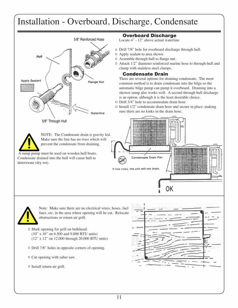
Installation - Overboard, Discharge, CondensateOverboard Discharge
Locate 4” - 12” above actual waterline
Drill 7/8” hole for overboard discharge through hull.Apply sealant to area shownAssemble through hull to flange nut.Attach 1/2” diameter reinforced marine hose to through-hull and clamp with stainless steel clamps.
Condensate DrainThere are several options for draining condensate. The most common method is to drain condensate into the bilge so the automatic bilge pump can pump it overboard. Draining into a shower sump also works well. A second through hull discharge is an option, although it is the least desirable choice.Drill 3/4” hole to accommodate drain hoseInstall 1/2” condensate drain hose and secure in place, making sure there are no kinks in the drain hose.
NOTE: The Condensate drain is gravity fed. Make sure the line has no rises which will prevent the condensate from draining.
A sump pump must be used on wooden hull boats.Condensate drained into the hull will cause hull todeteriorate (dry rot).
Note: Make sure there are no electrical wires, hoses, fuel lines, etc. in the area where opening will be cut. Relocate obstructions or return air grill.
Mark opening for grill on bulkhead:(10” x 10” on 6,500 and 9,000 BTU units)(12” x 12” on 12,000 through 20,000 BTU units)
Drill 7/8” holes in opposite corners of opening.
Cut opening with saber saw.
Install return air grill.
11
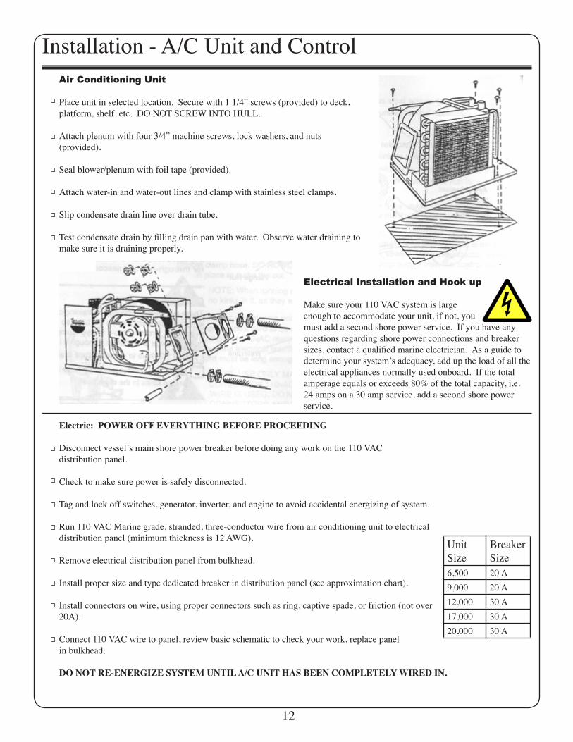
Installation - A/C Unit and ControlAir Conditioning Unit
Place unit in selected location. Secure with 1 1/4” screws (provided) to deck, platform, shelf, etc. DO NOT SCREW INTO HULL.
Attach plenum with four 3/4” machine screws, lock washers, and nuts(provided).
Seal blower/plenum with foil tape (provided).
Attach water-in and water-out lines and clamp with stainless steel clamps.
Slip condensate drain line over drain tube.
Test condensate drain by filling drain pan with water. Observe water draining to make sure it is draining properly.
Electrical Installation and Hook up
Make sure your 110 VAC system is largeenough to accommodate your unit, if not, youmust add a second shore power service. If you have anyquestions regarding shore power connections and breaker sizes, contact a qualified marine electrician. As a guide todetermine your systemʼs adequacy, add up the load of all theelectrical appliances normally used onboard. If the total amperage equals or exceeds 80% of the total capacity, i.e. 24 amps on a 30 amp service, add a second shore power service.
Electric: POWER OFF EVERYTHING BEFORE PROCEEDING
Disconnect vesselʼs main shore power breaker before doing any work on the 110 VACdistribution panel.
Check to make sure power is safely disconnected.
Tag and lock off switches, generator, inverter, and engine to avoid accidental energizing of system.
Run 110 VAC Marine grade, stranded, three-conductor wire from air conditioning unit to electrical distribution panel (minimum thickness is 12 AWG).
Remove electrical distribution panel from bulkhead.
Install proper size and type dedicated breaker in distribution panel (see approximation chart).
Install connectors on wire, using proper connectors such as ring, captive spade, or friction (not over 20A).
Connect 110 VAC wire to panel, review basic schematic to check your work, replace panelin bulkhead.
DO NOT RE-ENERGIZE SYSTEM UNTIL A/C UNIT HAS BEEN COMPLETELY WIRED IN.
UnitSize
BreakerSize
6,500 20 A9,000 20 A12,000 30 A17,000 30 A20,000 30 A
12
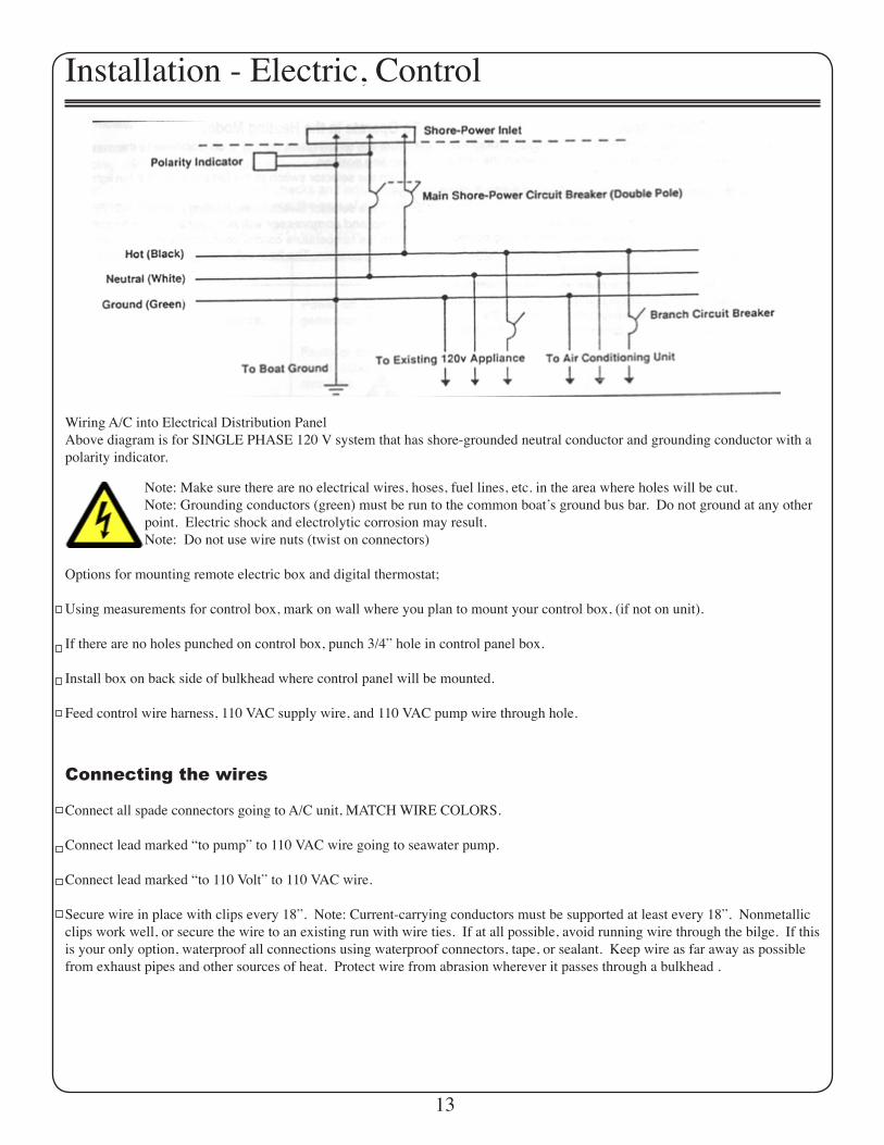
Installation - Electric, Control
Wiring A/C into Electrical Distribution PanelAbove diagram is for SINGLE PHASE 120 V system that has shore-grounded neutral conductor and grounding conductor with a polarity indicator.
Note: Make sure there are no electrical wires, hoses, fuel lines, etc. in the area where holes will be cut. Note: Grounding conductors (green) must be run to the common boatʼs ground bus bar. Do not ground at any other point. Electric shock and electrolytic corrosion may result. Note: Do not use wire nuts (twist on connectors)
Options for mounting remote electric box and digital thermostat;
Using measurements for control box, mark on wall where you plan to mount your control box, (if not on unit).
If there are no holes punched on control box, punch 3/4” hole in control panel box.
Install box on back side of bulkhead where control panel will be mounted.
Feed control wire harness, 110 VAC supply wire, and 110 VAC pump wire through hole.
Connecting the wires
Connect all spade connectors going to A/C unit, MATCH WIRE COLORS.
Connect lead marked “to pump” to 110 VAC wire going to seawater pump.
Connect lead marked “to 110 Volt” to 110 VAC wire.
Secure wire in place with clips every 18”. Note: Current-carrying conductors must be supported at least every 18”. Nonmetallic clips work well, or secure the wire to an existing run with wire ties. If at all possible, avoid running wire through the bilge. If this is your only option, waterproof all connections using waterproof connectors, tape, or sealant. Keep wire as far away as possible from exhaust pipes and other sources of heat. Protect wire from abrasion wherever it passes through a bulkhead .
13
LogicCircuit
R W Y G Blk
T1 T2 T3
T6 T5 T4H C
C C
F C
F C STransformer
To Temperature Control
HP S
LP SOptional
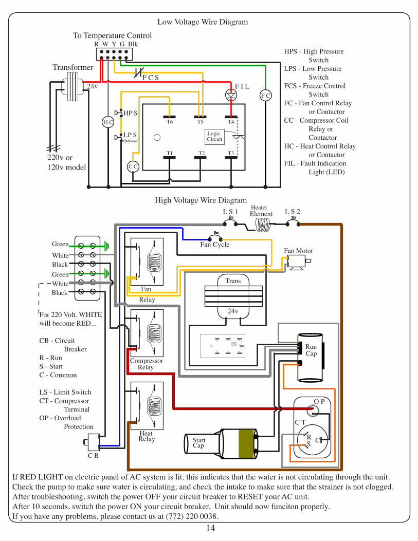
Low Voltage Wire Diagram
High Voltage Wire Diagram
Heat
Compressor
Start
RunCap
FanTrans
LogicCircuit
T1 T2 T3
T6 T5 T4
HeaterElementL S 1 L S 2
C B
RS C
HPS - High Pressure SwitchLPS - Low Pressure SwitchFCS - Freeze Control SwitchFC - Fan Control Relay or ContactorCC - Compressor Coil Relay or ContactorHC - Heat Control Relay or ContactorFIL - Fault Indication Light (LED)
Green
Green
White
White
Black
Black
Fan Motor
Relay
Relay
Cap
220v or120v model
F I L
Fan Cycle
Relay
For 220 Volt, WHITEwill become RED...
CB - Circuit BreakerR - RunS - StartC - Common
LS - Limit SwitchCT - Compressor TerminalOP - Overload Protection
O P
24v
C T
24v
If RED LIGHT on electric panel of AC system is lit, this indicates that the water is not circulating through the unit. Check the pump to make sure water is circulating, and check the intake to make sure that the strainer is not clogged. After troubleshooting, switch the power OFF your circuit breaker to RESET your AC unit.After 10 seconds, switch the power ON your circuit breaker. Unit should now funciton properly.If you have any problems, please contact us at (772) 220 0038.
14
LogicCircuit
R W Y G Blk
T1 T2 T3
T6 T5 T4HC1
C C
F C
F C STransformer
To Temperature Control
HP S
LP SOptional
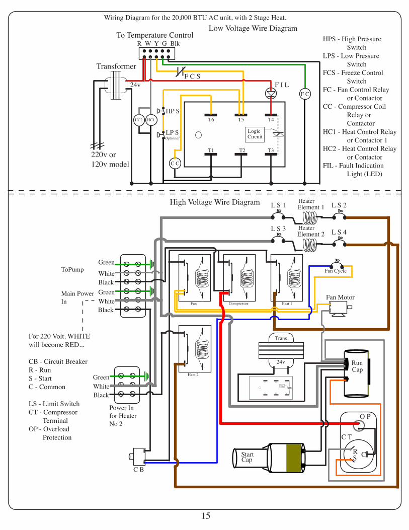
Low Voltage Wire Diagram
High Voltage Wire Diagram
Start
RunCap
Trans
LogicCircuit
T4 T5 T6
T3 T2 T1
HeaterElement 1L S 1 L S 2
C B
RS C
HPS - High Pressure SwitchLPS - Low Pressure SwitchFCS - Freeze Control SwitchFC - Fan Control Relay or ContactorCC - Compressor Coil Relay or ContactorHC1 - Heat Control Relay or Contactor 1HC2 - Heat Control Relay or ContactorFIL - Fault Indication Light (LED)
Green
Green
White
White
Black
Black
Fan Motor
Cap
220v or120v model
F I L
Fan Cycle
For 220 Volt, WHITEwill become RED...
CB - Circuit BreakerR - RunS - StartC - Common
LS - Limit SwitchCT - Compressor TerminalOP - Overload Protection
O P
24v
C T
24v
HeaterElement 2
L S 3 L S 4
Fan Compressor Heat 1
Heat 2GreenWhiteBlack
HC2
Wiring Diagram for the 20,000 BTU AC unit, with 2 Stage Heat.
ToPump
Main PowerIn
Power Infor HeaterNo 2
15
R
SC
Overload Protect
Compressor Term
StartCapacitor
RunCapacitor
Fan Motor
Heat Limit Switch Heat Limit Switch
Heater Element
Water Pump
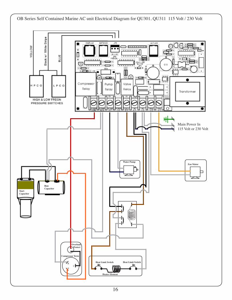
OB Series Self Contained Marine AC unit Electrical Diagram for QU301, QU311 115 Volt / 230 Volt
Main Power In115 Volt or 230 Volt
16
R
SC
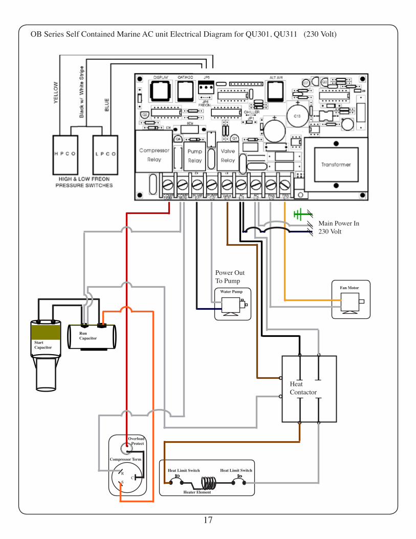
OB Series Self Contained Marine AC unit Electrical Diagram for QU301, QU311 (230 Volt)
Main Power In230 Volt
Power OutTo Pump
HeatContactor
17
Overload Protect
Compressor Term
StartCapacitor
RunCapacitor
Fan Motor
Heat Limit Switch Heat Limit Switch
Heater Element
Water Pump
Warranty Policy
All QME units are thoroughly inspected and tested before leaving the factory. Each unit is warranted to be free of defects from work-manship and material for a period of one (1) year from the date of purchase. Should any problem develop during this period, return the unit direct to the manufacturer. If inspection shows that the problem is caused by defective workmanship or material, QME will repair (or, at its option, replace) the system without charge.
If an EXTENDED WARRANTY has been purchased, this warranty will cover the repair or replacement of the condensor, compressor, or evaporator coil only. The labor to repair or replace these parts is not covered under the extended warranty.
Warranty does not apply if:- Repairs have been made or attempted by persons not authorized by QME.- Shore power voltage is either too low or high.- Repairs are required resulting from normal wear and tear.- Water supply is inadequate.- The system has been abused, misused or not properly maintained.
QME is not responsible for operation of or damage to any A/C or refrigeration system when only part of that system was replaced by QME.
QME is not responsible for any loss of business, damage to interior of boat, loss from flood, or insulation or repair charges.
QME shall not be liable for any indirect, incidental or consequential damages from the sale or use of this product. This disclaimer applies both during and after the term of the warranty. WARRANTY APPLIES TO ORIGINAL OWNER ONLY. Any legal complaints must be addressed in Martin County, Florida.
An additional two (2) year warranty can be purchased.
QUORUM MARINE AND ELECTRONICS INC.DBA OCEAN BREEZEFor service, call 772 220 0038 (USA),e-mail: [email protected], or SEND complete part [prepaid] to QME. Be sure to include a letter in the carton detailing theproblem with your part. COD’s will not be accepeted. ALL RETURNED PARTS MUST BE PRE-AUTHORIZED BY QME. Unclaimed units will be subject to a storage charge.
NO REFUNDS ON INSTALLED EQUIPMENT OR CUSTOM MADE EQUIPMENT. ALL SHIPPING FOB STUART, FLORIDA.CLAIMS FOR EQUIPMENT DAMAGED IN SHIPMENT ARE THE RESPONSIBILITY OF THE CUSTOMER. ALL WARRANTY WORK MUST BE DONE AT THE FACTORY IN STUART, FLORIDA.
During the first 90 days after purchase, QME will pay return charges to the factory. If the claim falls under the terms of the warranty policy, QME will pay return freight charges to the customer. After 90 days warranty returns must be shipped prepaid. If the claim falls under the warranty policy, QME will return the unit freight prepaid. After one year, freight charges for all warranty claims are paid by the customer. International Warranty covers parts only, shipping costs are the responsibility of the buyer. Pumps are covered by one (1) year warranty by the pump manufacturer and are subject to their warranty policy. All Commercial and Industrial equipment is covered by a one year warranty unless extended warranty agreement is purchased. No exceptions.
Returns made for reasons other than warranty claims must be made within two (2) weeks from the date of purchase and will be subject to a 25% restocking fee. Freight charges will not be refunded. Returns must be shipped prepaid in the original carton with ALL parts included. Equipment must be in the same condition as it was when it left the factory. Refunds will be made at the discretion of QME.
For international customers (meaning outside of the United States), shipping and handling is not covered under the warranty; it is the sole responsibility of the customer.
ABSOLUTELY NO REFUNDS ON CUSTOM MADE ORDERS.This warranty pertains to QME components. It does not warrant the suitability of QME products to any application. QME does notwarrant the installation of its products. Adequate cooling and/or heating capacity is the responsibility of the purchaser. QME takes no responsibility for component selection or sizing of units.
18