installing thermal (bulk) insulation - pages -...
TRANSCRIPT
Installing Thermal (Bulk)
InsulationTo achieve the requirements for
performance & safety
NOV 2007
HER.002.003.0002
CONTENTS
A. Introduction . . . . . . . . . . . . . . . . . . . . . . . . . . . . . . . . . . . . . . . . . . . . . . . . . . . . . . . . . 2
1. Installationstandards . . . . . . . . . . . . . . . . . . . . . . . . . . . . . . . . . . . . . . . . . . . . . . . 2
B. GeneralInstallationInformation . . . . . . . . . . . . . . . . . . . . . . . . . . . . . . . . . . . . . . . . . 3
1. Inspectandevaluatetheareatobeinsulated............................ 3 2. InsulatingaroundElectricalEquipmentandotherAppliances. . . . . . . . . . . . . . . . 3 a. ElectricalCablesandEquipment. . . . . . . . . . . . . . . . . . . . . . . . . . . . . . . . . . . 3 b. Surroundingelectricalcablesandwiringwithinsulation. . . . . . . . . . . . . . . . . 3 c. NewDIY&Tradespeopletakecare . . . . . . . . . . . . . . . . . . . . . . . . . . . . . . . . . 3 d. Downlights . . . . . . . . . . . . . . . . . . . . . . . . . . . . . . . . . . . . . . . . . . . . . . . . . . . . 4 e. OtherAppliances . . . . . . . . . . . . . . . . . . . . . . . . . . . . . . . . . . . . . . . . . . . . . . . 4 3. Maintainingperformance . . . . . . . . . . . . . . . . . . . . . . . . . . . . . . . . . . . . . . . . . . . . 5 4. Preparation. . . . . . . . . . . . . . . . . . . . . . . . . . . . . . . . . . . . . . . . . . . . . . . . . . . . . . . 6 a. WhatYouNeed . . . . . . . . . . . . . . . . . . . . . . . . . . . . . . . . . . . . . . . . . . . . . . . . 6 b. TheFirstStep. . . . . . . . . . . . . . . . . . . . . . . . . . . . . . . . . . . . . . . . . . . . . . . . . . 6
C. InsulatingRoofsandCeilings . . . . . . . . . . . . . . . . . . . . . . . . . . . . . . . . . . . . . . . . . . . 7
1. GeneralGuidelines. . . . . . . . . . . . . . . . . . . . . . . . . . . . . . . . . . . . . . . . . . . . . . . . . 7 2. LowPitchedRoofs. . . . . . . . . . . . . . . . . . . . . . . . . . . . . . . . . . . . . . . . . . . . . . . . . 8 a. MetalRoof . . . . . . . . . . . . . . . . . . . . . . . . . . . . . . . . . . . . . . . . . . . . . . . . . . . . 8 b. ConcreteRoof. . . . . . . . . . . . . . . . . . . . . . . . . . . . . . . . . . . . . . . . . . . . . . . . . 9 c. Suspendedceiling . . . . . . . . . . . . . . . . . . . . . . . . . . . . . . . . . . . . . . . . . . . . . . 9 3. Pitchedroofswithhorizontalceilings. . . . . . . . . . . . . . . . . . . . . . . . . . . . . . . . . . 10 a. Tile,MetalandConcreteRoofs . . . . . . . . . . . . . . . . . . . . . . . . . . . . . . . . . . . 10 4. Pitchedroofswithsloped/cathedralceilings . . . . . . . . . . . . . . . . . . . . . . . . . . . 11 a. TiledandFibreCementRoofs . . . . . . . . . . . . . . . . . . . . . . . . . . . . . . . . . . . . 11 b. MetalRoofs. . . . . . . . . . . . . . . . . . . . . . . . . . . . . . . . . . . . . . . . . . . . . . . . . . 11
D. InsulatingWalls . . . . . . . . . . . . . . . . . . . . . . . . . . . . . . . . . . . . . . . . . . . . . . . . . . . . . 12
1. GeneralGuidelines. . . . . . . . . . . . . . . . . . . . . . . . . . . . . . . . . . . . . . . . . . . . . . . . 12 2. FramedWalls . . . . . . . . . . . . . . . . . . . . . . . . . . . . . . . . . . . . . . . . . . . . . . . . . . . . 12 a. BrickVeneer. . . . . . . . . . . . . . . . . . . . . . . . . . . . . . . . . . . . . . . . . . . . . . . . . . 12 b. ConcreteandWeatherboard. . . . . . . . . . . . . . . . . . . . . . . . . . . . . . . . . . . . . 12 c. CavityBrickWalls(DoubleBrick). . . . . . . . . . . . . . . . . . . . . . . . . . . . . . . . . . 13
E. InsulatingSuspendedTimberFloors . . . . . . . . . . . . . . . . . . . . . . . . . . . . . . . . . . . . 13
1. GeneralGuidelines. . . . . . . . . . . . . . . . . . . . . . . . . . . . . . . . . . . . . . . . . . . . . . . . 13 2. NewConstruction–installationfromabove . . . . . . . . . . . . . . . . . . . . . . . . . . . . 13 3. Retrofitapplication–installationfrombelow . . . . . . . . . . . . . . . . . . . . . . . . . . . . 13
F. Safety,FirstAidandDisposal(asperbackofbag) . . . . . . . . . . . . . . . . . . . . . . . . 14
1. Safety . . . . . . . . . . . . . . . . . . . . . . . . . . . . . . . . . . . . . . . . . . . . . . . . . . . . . . . . . . 14 2. FirstAid . . . . . . . . . . . . . . . . . . . . . . . . . . . . . . . . . . . . . . . . . . . . . . . . . . . . . . . . 14 3. Disposal........................................................ 14
G. Glossary . . . . . . . . . . . . . . . . . . . . . . . . . . . . . . . . . . . . . . . . . . . . . . . . . . . . . . . . . . . 15
1
HER.002.003.0003

A. Introduction
This instruction guide is designed to assist home owners, builders, renovators and owner builders to install Fletcher Insulation™ thermal insulation in the correct manner to ensure maximum performance and to maintain safety.
These instructions are general in nature and cover the installation of glasswool and polyester insulation in roofs, ceilings, walls and floors for the most common construction types.
Building regulations and building methods vary across Australia, and these instructions do not intend to satisfy all requirements of all regulatory bodies.
NOTE: This guide refers to the installation of thermal (bulk) insulation only. The installation of reflective foil and laminates are not covered in this guide.
1. Installation standardsFor any further information regarding the installation of thermal insulation refer to the following Australian Standards and national codes of practice:
• Thermal (bulk) insulation must be installed in compliance with AS3999: Thermal insulation of dwellings – Bulk insulation – Installation requirements.
• All electrical wiring potentially covered with insulation must conform to AS3000: Electrical Installations – buildings, structures and premises.
2
HER.002.003.0004
B. General Installation Information
1. Inspect and evaluate the area to be insulatedInstalling insulation in most dwellings requires the installer to take precautions when insulating around electrical cables, built-in appliances, gas flues and other electrical equipment. Installing insulation, especially ceiling insulation from within the attic space, can present hazards which the installer should make a personal assessment of and take appropriate measures to ensure his/her safety.
2.Insulating around Electrical Equipment and other Appliancesa.ElectricalCablesandEquipment
When installing your own insulation, you must be extremely careful with the electrical wiring, electrical equipment and other appliances. In general, clear space around electrical cable and equipment is required to permit the dissipation of heat into their surrounding area, reducing the risk of fire from cables and appliances overheating.
You also need to consider the age of your home and therefore the possible age of your wiring/cables. If you have any concerns, it is best to check with an electrical contractor before commencing work.
I. ForBuildingsWiredtoAS3000-builtafter1986andbuilttothestandard
Where thermal insulation is to surround electrical cables, installation can be done as described in this guide, provided the thickness of the insulation doesn’t exceed 150mm (typically R3.0).
Where the insulation exceeds 150mm in thickness in the ceiling follow the instructions in B.2.a.ii described below.
II. ForBuildingsNotWiredtoAS3000-orbuiltbefore1986
In a building not wired in accordance with AS3000 or where thermal insulation would surround lengths of cable for 150mm or greater, there are two procedures that need to be followed:
1. Install the bulk insulation so that it does not surround or cover the cables either partially or completely.
2. Consult a licensed electrical contractor or electrical inspecting authority to ascertain whether the cables are suitable for surrounding in thermal insulation. If the cables are suitable proceed as normal. If the cables are unsuitable follow Point 1.
b.Surroundingelectricalcablesandwiringwithinsulation
Where possible the electrical cable and wiring should be placed above the insulation. However, surrounding cables with insulation can also be avoided by using a separating device, such as cardboard, to provide a minimum 5mm clear space/air gap from the insulation. The separator should be fixed in position, or held in position by the insulation. See Figure A or B.
c.NewDIY&Tradespeopletakecare
When installing insulation batt or blanket into ceiling, walls or floors care needs to be taken to ensure the areas to be worked in are safe and clean. Older type black coated electrical wires usually found in homes pre-1990 may have external protection deteriorated over the years exposing bare wires and also many split metal conduits have been seen in houses where they have lost their earthing continuity and become live. The advice is not to touch the conduits or older black wires and contact the electrician to carry out inspections and appropriate tests. Care and safety is always your first priority.
3
HER.002.003.0005
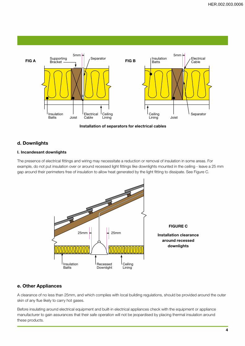
d.Downlights
I.Incandesantdownlights
The presence of electrical fittings and wiring may necessitate a reduction or removal of insulation in some areas. For example, do not put insulation over or around recessed light fittings like downlights mounted in the ceiling - leave a 25 mm gap around their perimeters free of insulation to allow heat generated by the light fitting to dissipate. See Figure C.
e.OtherAppliances
A clearance of no less than 25mm, and which complies with local building regulations, should be provided around the outer skin of any flue likely to carry hot gases.
Before insulating around electrical equipment and built-in electrical appliances check with the equipment or appliance manufacturer to gain assurances that their safe operation will not be jeopardised by placing thermal insulation around these products.
Installationofseparatorsforelectricalcables
FIGUREC
Installationclearancearoundrecessed
downlights
4
FIGA FIGB
HER.002.003.0006

FIGUREE
Placementofthermalinsulationtoeliminate
thermalbridging
3. Maintaining performanceTo achieve the best possible performance from your insulation you will need to follow these basic principles:
• Batts can easily be installed to a thickness greater than the ceiling joists. This will not restrict roof access as ceiling joists are usually still visible. It is important that batts are allowed to recover to their full thickness to ensure optimum insulation performance.
• Insulate internal walls between the house and uninsulated spaces such as garages and storerooms.
• Insulation needs to retain its thickness to achieve its specified R-value. Compressing the insulation reduces its effectiveness. If insulation batts are compressed by accident, they should be manoeuvred to their original thickness.
• Keep thermal insulation dry at all times as its performance may be inhibited if wet.
• Where insulation in different building elements meet (i.e. between walls, in ceilings, etc.) they should be butted together or overlapped.
• The insulation may need to be reduced or removed from areas around electrical wiring (see Section B.2.a)
• Insulation should be cut to fit neatly around any piping or other penetrations.
• Where there is a necessity to compress the insulation to suit the structure, a reduction in the R-value will occur. E.g. where blanket insulation is compressed between roof battens and roof sheeting (see Figure D)
• Avoid gaps in the insulation and make sure batts are firmly butted against each other and against ceiling joists and wall frames. (See Figure E)
FIGURED
Reductioninthicknessofblanketinsulationwhere
compressedbetweenroofsheetingandbattens
5
HER.002.003.0007

4. PreparationInstalling insulation is quite hot and physical work, so please remember that roof cavities can warm up significantly in summer, so do take care to assess the safety of your working environment and act accordingly.
a.WhatYouNeed
• A sharp knife & cutting board • Kneeling board (to span at least two full ceiling joists) • Lighting (if required) • Gloves (recommended) • A dust mask (recommended in enclosed spaces and for retro-fitting in existing buildings) • Goggles (recommended if working overhead)
b.TheFirstStep
Check the distance between studs or ceiling joists before purchasing your batts by measuring from the centre of one timber stud/ceiling joist to the next. For 450mm spacing use 430mm wide batts, for 600mm spacing use 580mm batts.Note: for ceiling batt installations 430mm wide batts for ceilings are perforated and can be torn in half and turned sideways to fit 600mm joist spacings. • Work out how many packs you need and pass them unopened through the manhole. • Spread the packs around inside the ceiling before opening the packs. • In the ceiling space only open one pack of insulation batts at a time. • Never walk on plaster ceilings. Stand on ceiling joists only. • Place kneeling board across at least two ceiling joists before kneeling. • Begin installation at the furthest point from the manhole and work your way closer.
C. Insulating Roofs and Ceilings1. General Guidelines 1. Always take into account the details provided in Section B. General Installation Information. 2. Remember to be extremely careful of electrical wiring in the ceiling. Refer to B.2 & C. 3. Thermal insulation, in the form of batts in ceilings, should be placed so that they extend at least 50mm past the
inside wall at the building’s perimeter to ensure that the space is enclosed fully (see Figure F).
6
FIGUREF
Extensionofceilinginsulationbeyondinsidefaceofwall
HER.002.003.0008
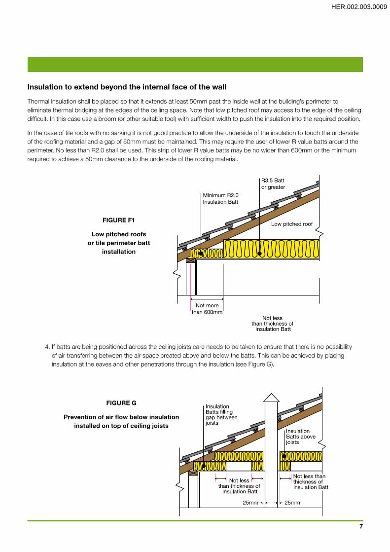
4. If batts are being positioned across the ceiling joists care needs to be taken to ensure that there is no possibility of air transferring between the air space created above and below the batts. This can be achieved by placing insulation at the eaves and other penetrations through the insulation (see Figure G).
7
FIGUREG
Preventionofairflowbelowinsulationinstalledontopofceilingjoists
Minimum R2.0Insulation Batt
R3.5 Battor greater
Low pitched roof
Not morethan 600mm
FIGUREF1
Lowpitchedroofsortileperimeterbatt
installation
Insulationtoextendbeyondtheinternalfaceofthewall
Thermal insulation shall be placed so that it extends at least 50mm past the inside wall at the building’s perimeter to eliminate thermal bridging at the edges of the ceiling space. Note that low pitched roof may access to the edge of the ceiling difficult. In this case use a broom (or other suitable tool) with sufficient width to push the insulation into the required position.
In the case of tile roofs with no sarking it is not good practice to allow the underside of the insulation to touch the underside of the roofing material and a gap of 50mm must be maintained. This may require the user of lower R value batts around the perimeter. No less than R2.0 shall be used. This strip of lower R value batts may be no wider than 600mm or the minimum required to achieve a 50mm clearance to the underside of the roofing material.
HER.002.003.0009

5. When a drop section in the ceiling or cavity is formed (eg. above a cupboard) the vertical and horizontal surfaces should be insulated with insulation of the same R-value as the ceiling insulation. Vertical surfaces will require the insulation to be supported with suitable support material (see Figure H).
6. If insulation batts are to cover the drop ceiling or cavity and not line it, the batts must be supported underneath with a suitable support to keep it in the same position and level with the ceiling (see Figure I).
7. To properly complete the installation process you must remember to fix an appropriately sized section of insulation batt to the top of the manhole cover.
2. Low Pitched Roofs2.1 Blanket InsulationGeneralGuidelines Care: At all times care is needed in the handling loading and unloading of the blanket rolls with or without Sisalation® foil. Do not throw rolls onto the roofs or into ceilings and ensure the blanket rolls do not fall back to the ground and damage the product.
2.2Recovery Installation of blanket insulation (Permastop™ or Vapa-Chek™) should ensure that it is placed in position to allow for full recovery to the desired height to ensure the material R value applicable is achieved.
2.3RidgeInstallationforblanket It is desirable to ensure correct installation of blankets along the ridge so that the blankets from both sides butt against each other or lap in accordance with specifiers requirements including any special instructions for the moisture barrier sought for the particular project.
2.4RoofingBattens It is desirable to ensure the blanket when installed and subject to the project specifications as detailed to ensure battens are
FIGUREHFIGUREI
Alternativetreatmentsfordropceilingsorcavitiesbelowceilingline
8
HER.002.003.0010

in place to allow for full recovery to nominated material thickness to achieve the R value applicable and to conform with the relevant BCA guidelines as shown. If this is not able to be achieved then advise the project supervisor so he can rectify the situation before installation of the nominated blanket.
Installation for low pitched roofs should be as follows:
a.MetalRoof
1. Blanket insulation (Permastop™ or Vapa-Chek™) should be positioned above the roofing battens and in contact with the sheet roof.
2. For areas prone to high humidity such as above bathrooms the addition of a vapour barrier (Sisalation®) restricts any condensation that may form, and prevents it from affecting the batt insulation in the ceilings. This allows for ventilation of the roof space without affecting the effectiveness of the insulation.
3. For situations where the beams are below the ceiling lining refer to Figure N and O in c.4. In this case the blanket insulation should be installed between counter battens. These figures illustrate a sloping ceiling but the same principal applies for installing insulation in low pitched roofs.
4. Figure K shows the positioning of blanket insulation where the supporting beam is above the ceiling lining.
5. The addition of insulation batts on the ceiling lining in conjunction with the blanket under the sheet roofing aids in adhering the desired R-value.
b.ConcreteRoof
1. When insulating the underside of a low-pitched concrete roof the insulation, Permastop or Vapa-Chek blanket should be fixed directly beneath with the foil facing down. It should be held in place with mechanical fasteners.
c.Suspendedceiling
1. When installing insulation batts in a suspended ceiling, the batts should be placed directly onto the ceiling lining and firmly butted together.
b) Blanket Insulation in contact with sheet roofingand Insulation Batts on vapour barrier or foil faced blanket
FIGUREK
(Inpart)insulationofhorizontalceilingswithflatorlow-pitched
metalroofs
9
HER.002.003.0011

3. Pitched roofs with horizontal ceilingsPitched roofs with horizontal ceilings are the most common roofing in domestic buildings.
a.Tile,MetalandConcreteRoofs
1. Batts can be laid between the ceiling joists directly on to the ceiling lining as shown in Figure L.
2. Ensure the batts are butted closely together so there are no gaps.
3. Cut the batts to the required size to fit around vents, exhaust fans and flue pipes, allowing a space of at least 25mm.
4. Continue until the entire ceiling area is covered, and extending a minimum of 50mm onto the external wall top plate.
5. Offcuts may be used to fill small spaces to ensure a complete coverage.
6. Under a metal roof, blanket insulation adhered to a vapour barrier (such as Permastop or Vapa-Chek) should be installed directly under the roof sheeting as described in section C.2. This should be done in conjunction with installing insulation batts directly on to the ceiling lining where necessary.
FIGUREL
Insulationofhorizontalceilingwithpitched,tiledroofs
10
HER.002.003.0012
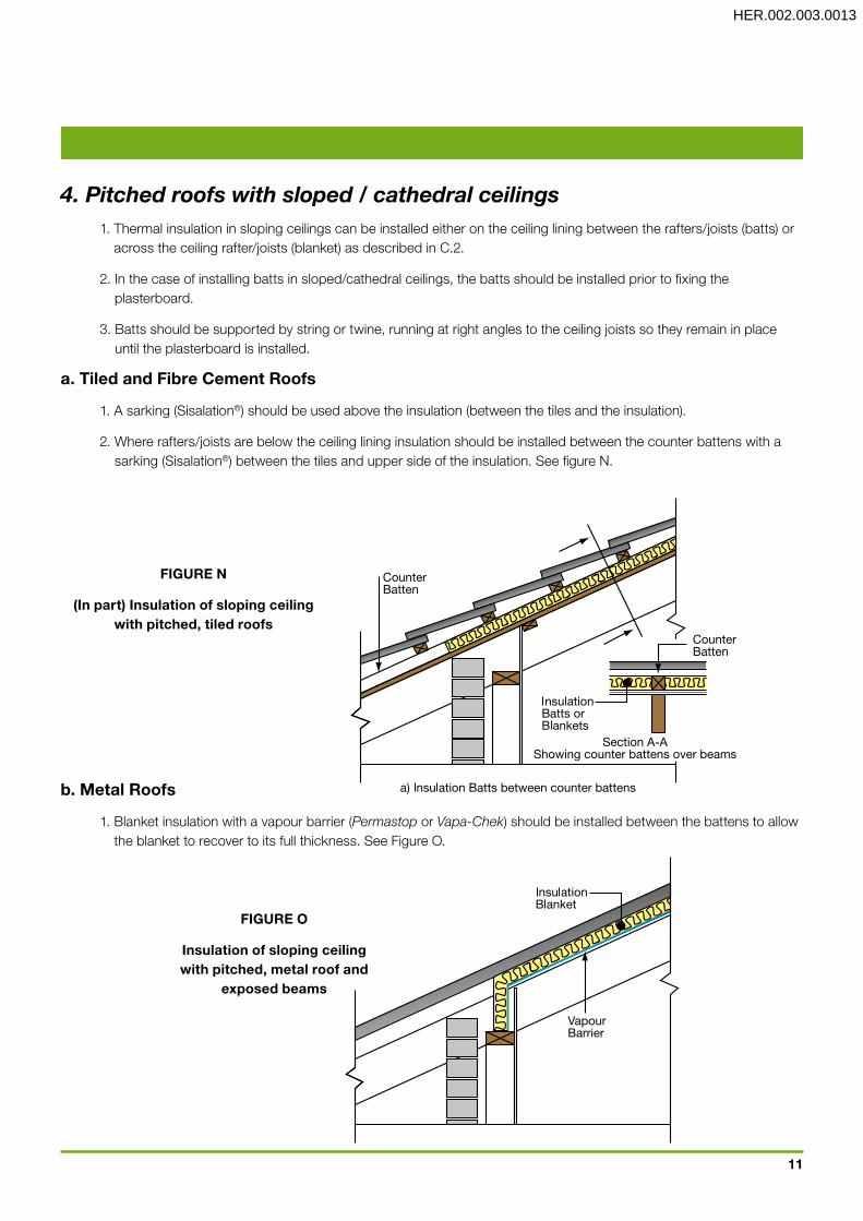
4. Pitched roofs with sloped / cathedral ceilings 1. Thermal insulation in sloping ceilings can be installed either on the ceiling lining between the rafters/joists (batts) or
across the ceiling rafter/joists (blanket) as described in C.2.
2. In the case of installing batts in sloped/cathedral ceilings, the batts should be installed prior to fixing the plasterboard.
3. Batts should be supported by string or twine, running at right angles to the ceiling joists so they remain in place until the plasterboard is installed.
a.TiledandFibreCementRoofs
1. A sarking (Sisalation®) should be used above the insulation (between the tiles and the insulation).
2. Where rafters/joists are below the ceiling lining insulation should be installed between the counter battens with a sarking (Sisalation®) between the tiles and upper side of the insulation. See figure N.
b.MetalRoofs
1. Blanket insulation with a vapour barrier (Permastop or Vapa-Chek) should be installed between the battens to allow the blanket to recover to its full thickness. See Figure O.
FIGUREN
(Inpart)Insulationofslopingceilingwithpitched,tiledroofs
FIGUREO
Insulationofslopingceilingwithpitched,metalroofand
exposedbeams
11
HER.002.003.0013
D. Insulating Walls
1. General Guidelines 1. In the cavity of walls and bulkheads, thermal insulation batts should be cut to size to fit around cables or pipes. 2. By removing the plasterboard lining of existing walls you can access the wall cavity and install insulation batts.
However, this can be costly and often difficult to access. A lack of wall insulation can be compensated for, to some extent by using a higher R-value in the ceiling and/or floor insulation.
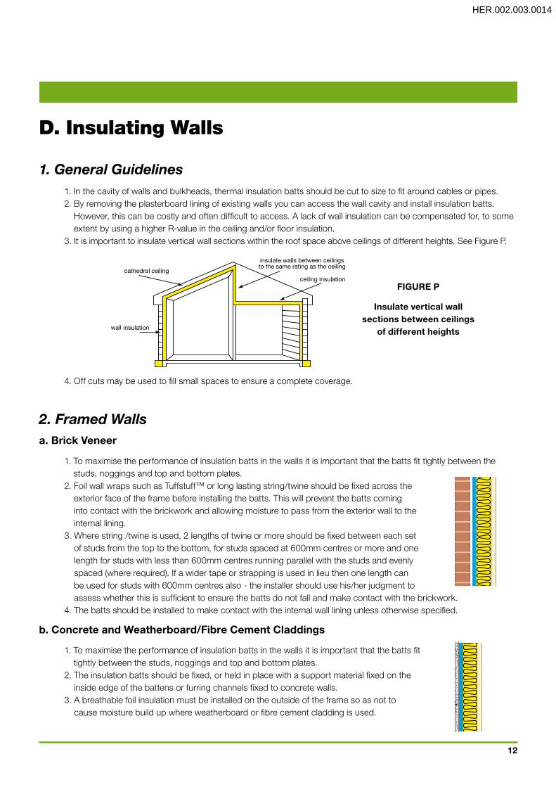
3. It is important to insulate vertical wall sections within the roof space above ceilings of different heights. See Figure P.
4. Off cuts may be used to fill small spaces to ensure a complete coverage.
2. Framed Wallsa.BrickVeneer
1. To maximise the performance of insulation batts in the walls it is important that the batts fit tightly between the studs, noggings and top and bottom plates.
2. Foil wall wraps such as Tuffstuff™ or long lasting string/twine should be fixed across the exterior face of the frame before installing the batts. This will prevent the batts coming into contact with the brickwork and allowing moisture to pass from the exterior wall to the internal lining.
3. Where string /twine is used, 2 lengths of twine or more should be fixed between each set of studs from the top to the bottom, for studs spaced at 600mm centres or more and one length for studs with less than 600mm centres running parallel with the studs and evenly spaced (where required). If a wider tape or strapping is used in lieu then one length can be used for studs with 600mm centres also - the installer should use his/her judgment to assess whether this is sufficient to ensure the batts do not fall and make contact with the brickwork.
4. The batts should be installed to make contact with the internal wall lining unless otherwise specified.
b.ConcreteandWeatherboard/FibreCementCladdings
1. To maximise the performance of insulation batts in the walls it is important that the batts fit tightly between the studs, noggings and top and bottom plates.
2. The insulation batts should be fixed, or held in place with a support material fixed on the inside edge of the battens or furring channels fixed to concrete walls.
3. A breathable foil insulation must be installed on the outside of the frame so as not to cause moisture build up where weatherboard or fibre cement cladding is used.
FIGUREP
Insulateverticalwallsectionsbetweenceilings
ofdifferentheights
12
HER.002.003.0014

c.CavityBrickWalls(DoubleBrick)
1. Insulation batts are not recommended for use in cavity brick construction.
E. Insulating Suspended Timber Floors
1. General GuidelinesThe following illustrates how to insulate a floor to reduce heat loss, cold draughts and noise.Providing there is adequate space under an existing floor, underfloor insulation (Cosyfloor™) can be used in a new construction or retrofit application.It is also important to maintain sufficient ventilation to satisfy local building requirements to prevent rotting as per AS/NZS 1860.
2. New Construction or Retrofit application Installation from above 1. Commence working from one side of the area to be insulated. 2. Open the pack of Cosyfloor insulation and using one roll at a time, roll the product out into the joist spacing so that
the top edges of the product are flush with the top of the timber floor joists. 3. Fix the product in place by pinching a small section of blanket and stapling it to the side of the timber floor joists
every 300mm. 4. Keep the product smooth and tight as you move down the length of the floor joist. 5 The insulation should fit tightly between joists and extend past the inside face of the walls no less than 50mm to fully
enclose the space being insulated. See Figure Q. 6. Run Sisalation® across top of bearers before fixing joists.
Installation from below 1. Commence working from one side of the area to be insulated. 2. Open the pack of Cosyfloor insulation and using one roll at a time, work your way down the length of the timber
floor joists rolling out the product pushing it flush against the floor boards. 3. Fix the product in place by pinching a small section of blanket and stapling it to the side of the timber floor joists
every 300mm. 4. Keep the product smooth and tight as you move down the length of the floor joist. 5. The insulation should fit tightly between joists and extend past the inside face of the walls no less than 50mm to
fully enclose the space being insulated. See Figure R. 6. Run Sisalation® across the underside of joists.
13
FIGUREQ
Newconstructioninstallation
FIGURER
Retrofitfloorinstallation
HER.002.003.0015
F. Safety, First Aid & Disposal (as per back of bag)
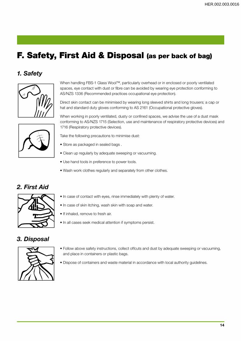
1. Safety When handling FBS-1 Glass Wool™, particularly overhead or in enclosed or poorly ventilated
spaces, eye contact with dust or fibre can be avoided by wearing eye protection conforming to AS/NZS 1336 (Recommended practices occupational eye protection).
Direct skin contact can be minimised by wearing long sleeved shirts and long trousers; a cap or hat and standard duty gloves conforming to AS 2161 (Occupational protective gloves).
When working in poorly ventilated, dusty or confined spaces, we advise the use of a dust mask conforming to AS/NZS 1715 (Selection, use and maintenance of respiratory protective devices) and 1716 (Respiratory protective devices).
Take the following precautions to minimise dust:
• Store as packaged in sealed bags .
• Clean up regularly by adequate sweeping or vacuuming.
• Use hand tools in preference to power tools.
• Wash work clothes regularly and separately from other clothes.
2. First Aid • In case of contact with eyes, rinse immediately with plenty of water.
• In case of skin itching, wash skin with soap and water.
• If inhaled, remove to fresh air.
• In all cases seek medical attention if symptoms persist.
3. Disposal • Follow above safety instructions, collect offcuts and dust by adequate sweeping or vacuuming,
and place in containers or plastic bags.
• Dispose of containers and waste material in accordance with local authority guidelines.
14
HER.002.003.0016
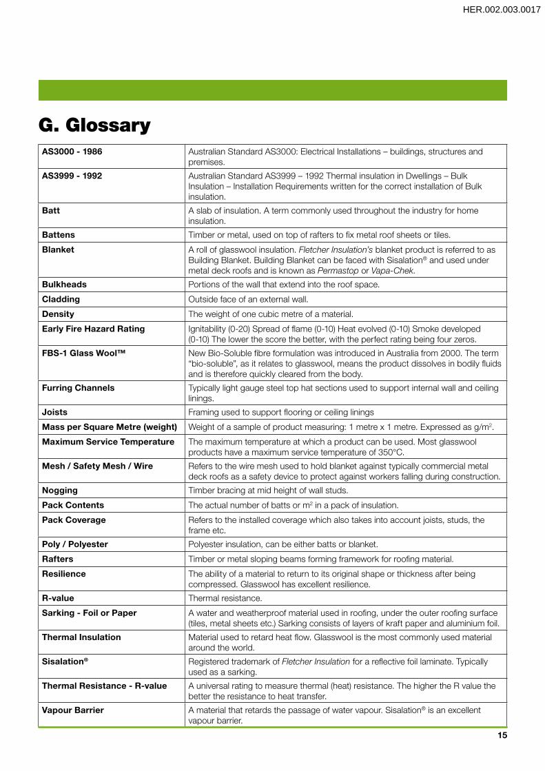
AS3000-1986 Australian Standard AS3000: Electrical Installations – buildings, structures and premises.
AS3999-1992 Australian Standard AS3999 – 1992 Thermal insulation in Dwellings – Bulk Insulation – Installation Requirements written for the correct installation of Bulk insulation.
Batt A slab of insulation. A term commonly used throughout the industry for home insulation.
Battens Timber or metal, used on top of rafters to fix metal roof sheets or tiles.
Blanket A roll of glasswool insulation. Fletcher Insulation’s blanket product is referred to as Building Blanket. Building Blanket can be faced with Sisalation® and used under metal deck roofs and is known as Permastop or Vapa-Chek.
Bulkheads Portions of the wall that extend into the roof space.
Cladding Outside face of an external wall.
Density The weight of one cubic metre of a material.
EarlyFireHazardRating Ignitability (0-20) Spread of flame (0-10) Heat evolved (0-10) Smoke developed (0-10) The lowerthe score the better, with the perfect rating being four zeros.
FBS-1GlassWool™ New Bio-Soluble fibre formulation was introduced in Australia from 2000. The term “bio-soluble”, as it relates to glasswool, means the product dissolves in bodily fluids and is therefore quickly cleared from the body.
FurringChannels Typically light gauge steel top hat sections used to support internal wall and ceiling linings.
Joists Framing used to support flooring or ceiling linings
MassperSquareMetre(weight) Weight of a sample of product measuring: 1 metre x 1 metre. Expressed as g/m2.
MaximumServiceTemperature The maximum temperature at which a product can be used. Most glasswool products have a maximum service temperature of 350°C.
Mesh/SafetyMesh/Wire Refers to the wire mesh used to hold blanket against typically commercial metal deck roofs as a safety device to protect against workers falling during construction.
Nogging Timber bracing at mid height of wall studs.
PackContents The actual number of batts or m2 in a pack of insulation.
PackCoverage Refers to the installed coverage which also takes into account joists, studs, the frame etc.
Poly/Polyester Polyester insulation, can be either batts or blanket.
Rafters Timber or metal sloping beams forming framework for roofing material.
Resilience The ability of a material to return to its original shape or thickness after being compressed. Glasswool has excellent resilience.
R-value Thermal resistance.
Sarking-FoilorPaper A water and weatherproof material used in roofing, under the outer roofing surface (tiles, metal sheets etc.) Sarking consists of layers of kraft paper and aluminium foil.
ThermalInsulation Material used to retard heat flow. Glasswool is the most commonly used material around the world.
Sisalation® Registered trademark of Fletcher Insulation for a reflective foil laminate. Typically used as a sarking.
ThermalResistance-R-value A universal rating to measure thermal (heat) resistance. The higher the R value the better the resistance to heat transfer.
VapourBarrier A material that retards the passage of water vapour. Sisalation® is an excellent vapour barrier.
G. Glossary
15
HER.002.003.0017

NOV 2007
NOTE: Fletcher Insulation reserves the right to change product specifications without prior notification. Information in this publication and otherwise supplied to users as to the subject product is based on our general experience and is given in good faith. However, because of the many particular factors which are outside our knowledge and control and affect the use of products, no warranty is given or is to be implied with respect to either such information or product itself, in particular the suitability of the product for any particular purpose. The purchaser should independently determine the suitability of the product for the intended application. YPA/9443/NOV07
1800 000 878 Technical & Sales1300 65 44 44
www.insulation.com.au
Fletcher Insulation (NSW) Pty Ltd ABN 72 001 175 355 Trading as Fletcher Insulation.161 Arthur Street, Homebush, NSW Australia 2140. Phone +61 2 9752 9200 +61 2 9764 3175
INSTALLERS CHECKLIST
Prior to completion the installation shall be inspected to ensure that:
All ceilings batts have been installed without any gaps.
All Walls batts have been installed fully without any gaps
Ensure all batts or blankets if used have been trimmed around penetrations and around electrical equipment to ensure you have maintained their minimum clearance (typically 25mm)
Ensure that any down-light transformers are not covered by insulation.
Ensure that ceiling batts have recovered to their full thickness.
To visually ensure that no damage has been done during installation, if this has happened report the incidence to the owner/site manager so it may be rectified
Ensure that all off-cuts have been removed and site left tidy.
Ensure all packaging is removed.
Ensure you remove away all rubbish appropriately and in accordance with local by laws and or clients/site managers directions.
Check that all your tools and equipment have been collected from the job site.
That the warranty certificate has been signed (if required)
Have the client/site manager sign your completed work / job sheet.
Remember the client you have left happy after completing a good job will be your best source of referrals for further work.
HER.002.003.0018