installing embedded linux on zedboard - laas · 2017-02-23 · installing embedded linux on...
TRANSCRIPT
Installing Embedded Linux on ZedBoard
Clément Foucher (homepage)[email protected]
LAAS�CNRSLaboratoire d'analyse et d'architecture des systèmes
Version 1.1
This work is licensed under the Creative CommonsAttribution-ShareAlike 4.0 International License.
To view a copy of this license,visit http://creativecommons.org/licenses/by-sa/4.0/.
February 23, 2017
Contents
1 Before starting 51.1 Document purpose . . . . . . . . . . . . . . . . . . . . . . . . . . . . . . . . . . . . 51.2 Disclaimer . . . . . . . . . . . . . . . . . . . . . . . . . . . . . . . . . . . . . . . . . 61.3 Tools revisions and OS . . . . . . . . . . . . . . . . . . . . . . . . . . . . . . . . . . 61.4 Administrator privileges . . . . . . . . . . . . . . . . . . . . . . . . . . . . . . . . . 61.5 Conventions and directories . . . . . . . . . . . . . . . . . . . . . . . . . . . . . . . 61.6 Projects . . . . . . . . . . . . . . . . . . . . . . . . . . . . . . . . . . . . . . . . . . 71.7 Scripts and logs . . . . . . . . . . . . . . . . . . . . . . . . . . . . . . . . . . . . . . 71.8 Environment packages and libraries . . . . . . . . . . . . . . . . . . . . . . . . . . . 7
1.8.1 Fedora 22 Workstation . . . . . . . . . . . . . . . . . . . . . . . . . . . . . . 71.8.2 Ubuntu 16.04 LTS . . . . . . . . . . . . . . . . . . . . . . . . . . . . . . . . 8
2 Additional technical information 92.1 Downloading required sources . . . . . . . . . . . . . . . . . . . . . . . . . . . . . . 92.2 ZedBoard boot process . . . . . . . . . . . . . . . . . . . . . . . . . . . . . . . . . . 92.3 Reinitializing the SD card to factory state . . . . . . . . . . . . . . . . . . . . . . . 10
2.3.1 Restore partition scheme . . . . . . . . . . . . . . . . . . . . . . . . . . . . 102.3.2 Restore �les . . . . . . . . . . . . . . . . . . . . . . . . . . . . . . . . . . . . 10
3 Preparing the environment 113.1 Con�guring the scripts . . . . . . . . . . . . . . . . . . . . . . . . . . . . . . . . . . 113.2 Creating the project . . . . . . . . . . . . . . . . . . . . . . . . . . . . . . . . . . . 11
4 Hardware layout and low-level software 124.1 Creating a base hardware design . . . . . . . . . . . . . . . . . . . . . . . . . . . . 12
4.1.1 Default con�guration using script . . . . . . . . . . . . . . . . . . . . . . . . 124.1.2 Manual procedure . . . . . . . . . . . . . . . . . . . . . . . . . . . . . . . . 12
4.2 Generating the device tree . . . . . . . . . . . . . . . . . . . . . . . . . . . . . . . . 134.2.1 Downloading the device tree generator . . . . . . . . . . . . . . . . . . . . . 134.2.2 Generating the device tree . . . . . . . . . . . . . . . . . . . . . . . . . . . . 13
4.3 Generating the �rst stage boot loader . . . . . . . . . . . . . . . . . . . . . . . . . 144.4 Generating the bootloader . . . . . . . . . . . . . . . . . . . . . . . . . . . . . . . . 14
4.4.1 Default con�guration using script . . . . . . . . . . . . . . . . . . . . . . . . 144.4.2 Manual procedure . . . . . . . . . . . . . . . . . . . . . . . . . . . . . . . . 14
4.5 Generating the Binary �le . . . . . . . . . . . . . . . . . . . . . . . . . . . . . . . . 15
5 Generating Linux 175.1 Generating the kernel . . . . . . . . . . . . . . . . . . . . . . . . . . . . . . . . . . 17
5.1.1 Default con�guration using script . . . . . . . . . . . . . . . . . . . . . . . . 175.1.2 Custom con�guration using script . . . . . . . . . . . . . . . . . . . . . . . 175.1.3 Manual procedure . . . . . . . . . . . . . . . . . . . . . . . . . . . . . . . . 18
5.2 Generating the device tree blob . . . . . . . . . . . . . . . . . . . . . . . . . . . . . 18
2
CONTENTS 3
5.2.1 Default con�guration using script . . . . . . . . . . . . . . . . . . . . . . . . 195.2.2 Manual procedure . . . . . . . . . . . . . . . . . . . . . . . . . . . . . . . . 19
5.3 Generating the �le system . . . . . . . . . . . . . . . . . . . . . . . . . . . . . . . . 195.3.1 Default con�guration using script . . . . . . . . . . . . . . . . . . . . . . . . 195.3.2 Custom con�guration using script . . . . . . . . . . . . . . . . . . . . . . . 195.3.3 Manual procedure . . . . . . . . . . . . . . . . . . . . . . . . . . . . . . . . 20
6 Preparing the board 216.1 Partitioning the SD card . . . . . . . . . . . . . . . . . . . . . . . . . . . . . . . . . 216.2 Copying the �le system on the card . . . . . . . . . . . . . . . . . . . . . . . . . . . 21
6.2.1 Using the script . . . . . . . . . . . . . . . . . . . . . . . . . . . . . . . . . . 216.2.2 Manually . . . . . . . . . . . . . . . . . . . . . . . . . . . . . . . . . . . . . 22
6.3 Copying the system �les . . . . . . . . . . . . . . . . . . . . . . . . . . . . . . . . . 22
7 Working on the board 237.1 Hardware con�guration . . . . . . . . . . . . . . . . . . . . . . . . . . . . . . . . . 237.2 On the �rst boot . . . . . . . . . . . . . . . . . . . . . . . . . . . . . . . . . . . . . 23
7.2.1 SSH con�guration . . . . . . . . . . . . . . . . . . . . . . . . . . . . . . . . 237.3 Using Xilinx SDK to create an application . . . . . . . . . . . . . . . . . . . . . . . 24
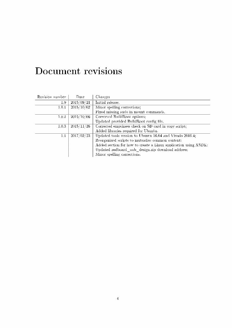
Document revisions
Revision number Date Changes
1.0 2015/09/21 Initial release.1.0.1 2015/10/02 Minor spelling corrections;
Fixed missing sudo in mount commands.1.0.2 2015/10/06 Corrected BuildRoot options;
Updated provided BuildRoot con�g �le.1.0.3 2015/11/26 Corrected emptiness check on SD card in copy script;
Added libraries required for Ubuntu.1.1 2017/02/23 Updated tools version to Ubuntu 16.04 and Vivado 2016.4;
Reorganized scripts to mutualize common content;Added section for how to create a Linux application using XSDK;Updated zedboard_oob_design.zip download address;Minor spelling corrections.
4
Chapter 1
Before starting
Please read this chapter carefully before starting, as it contains valuable information that you'llrequire all along this document.
1.1 Document purpose
This document is a tutorial describing how to build an Embedded Linux system for use on aZedBoard development board. Following this procedure, you'll obtain an Embedded Linux runningon a persistent �le system, which you can use as a base for your further developments. This tutorialdescribes every needed step, from scratch to a running system, and provides scripts to automatemost of the steps.
The con�guration depicted here will be the very minimum. It is only intended to show youthe global approach, letting you build you own personal system matching your needs once you'veunderstood how to do. The only addition we do to the bare minimum system is to enable anEthernet connection, in order to allow remote control of the board using SSH.
All needed tools are open-source and can be downloaded using the scripts provided with thistutorial, except for Xilinx Vivado which requires a license.
You should have obtained this document inside an archive containing the scripts and other�les used in the procedure. If you don't have this archive, you can download it at this address:https://homepages.laas.fr/cfoucher/drupal/zedboard-development.
Each section in this tutorial presents how to build one speci�c �le. Most �le generationprocedures will be presented using three di�erent ways. For each step, choose the way thatcorrespond the most to you.
These sections use the following names:
Default con�guration using script
This �rst way uses dedicated scripts to run the default con�guration without any user interaction.This is the fastest way to build the target, but you'll be dependent on parameters I chose for you.
Custom con�guration using script
If any customization is available for a �le generation, I provide this second way of generatingit. It is still scripted, but opens a customization window which let you select your preferredcon�guration. This is the fastest way to choose your personal con�guration, while still hiding thedetails on how things are done.
5
6 CHAPTER 1. BEFORE STARTING
Manual procedure
Finally, this third way will present all required details to perform the full procedure manually.This is how you should proceed to learn the generation steps and re-use them outside this tutorial.
1.2 Disclaimer
The procedure depicted in this document is intended to help you build an Embedded Linux systemwhatever your knowledge of the Linux system is.
It should be relatively safe, but some steps require advanced manipulations on your host system,ZedBoard platform and related peripherals, including the SD card provided with ZedBoard.
The author or its institution cannot be held responsible for any harm caused to your hostsystem, ZedBoard platform or any element manipulated by the following tutorial.
Moreover, the author can't be held responsible for English misspelling that is probably presentin this document ;-). Please inform me of any error using my e-mail on the front page.
1.3 Tools revisions and OS
The procedure described in this document has been conducted using Xilinx Vivado 2016.4 onFedora 22 Workstation 64 bits and Ubuntu 16.04 LTS 64 bits. Some steps of the procedure areclosely related to tools version, so I cannot guarantee this tutorial will work using a di�erentversion of Vivado, a di�erent Linux distribution, a di�erent Fedora or Ubuntu version, or anyother version of a tool used in this tutorial.
If your system does not run a native Linux OS, you can install for free a Linux virtual machinematching the above speci�cations.
1.4 Administrator privileges
Some of the manipulations described in this document require root privileges. To obtain them,use the sudo command in order to get administrator privileges for the current command.
These commands require you entering your password to work, and the current user must beregistered in the sudo privileges list. If you're not familiar with the sudo command, you'll �nd allneeded information about it online or by typing man sudo in a console.
1.5 Conventions and directories
The host system is the system used to generate the �les, while the target system is the EmbeddedLinux system that will be generated.
Texts beginning by $ are shell commands to be typed in the console, without the initial $.Other texts written using monospaced characters are to be typed as it.
Paths are displayed in monospaced blue. Paths ending with a / are directories (e.g., ${BASEDIR}/scripts/), while the others are �les (e.g., ${BASEDIR}/scripts/initialize_project.sh).
In the current tutorial, we use the syntax ${DIRECTORY} to refer to speci�c paths. Notably,${BASEDIR}/ is the base working directory provided in the archive coming with this tutorial. Ifyou obtained this �le from the complete archive, the current �le is located in ${BASEDIR}/doc/.Please make sure the ${BASEDIR}/ path does not contain any space.
These kinds of paths are to be replaced by the user when doing the manipulation using matchingdirectory. E.g., if the base directory is /home/user/ZedBoard/, user has to understand occurrencesof ${BASEDIR}/scripts/ as /home/user/ZedBoard/scripts/. This can be achieved by manuallyreplacing the variable in the command line, or by de�ning the variable content before typing thecommand. Using the previous example, de�ning the ${BASEDIR} variable value would beachieved by typing the following command:
1.6. PROJECTS 7
$ export BASEDIR="/home/user/ZedBoard/"
If you choose to use manual procedures, you're not required to work in the ${BASEDIR}/ tree.Thus, these sections rather refer to another directory called ${CUSTOMDIR}/ which can be anydirectory you want.
1.6 Projects
A project is a set of both hardware design and software environment generation. Projectsare located in ${BASEDIR}/projects/. The base folder of project ${project_name} will be${BASEDIR}/projects/${project_name}/, and will be referred to as ${PROJECT_ROOT}/.
Variables ${project_name} and ${PROJECT_ROOT} can be set the same way as vari-able ${BASEDIR} (see Section 1.5).
1.7 Scripts and logs
Most of the manipulations depicted in this document provide scripts to automate the procedure.These scripts should work whatever the directory they are called from, but if anything fails, youshould try cd to ${BASEDIR}/scripts/ directory and use the ./<script_name>.sh syntax.
These scripts usually create a log �le in ${PROJECT_ROOT}/logs/<script_name>.log. Youcan check for this �le after a script run for more information about errors that might have occurred.
1.8 Environment packages and libraries
First, Vivado is required, and the installation must provide SDK, which is facultative in theinstallation process, so make sure it is installed. 2016.4 version in used in this tutorial. AsVivado only supports 64-bit OS versions, the procedure depicted here assumes you run in such anenvironment.
Moreover, some libraries and tools are required on the host system to execute this procedure.The following sections list the required packages.
1.8.1 Fedora 22 Workstation
Here are the main packages required for a bare Fedora 22 Workstation installation, but some othermay be required depending on your con�guration.
• gcc
• gcc-c++
• git
• qt4-devel
• �ex
• bison
• patch
• ncurses-devel
• openssl-devel
• gparted
• glibc.i686
8 CHAPTER 1. BEFORE STARTING
Before starting, you can use the following command in order to ensure all needed libraries areavailable on your system:
$ sudo dnf install gcc gcc-c++ git qt4-devel flex bison patch ncurses-devel \$ openssl-devel gparted glibc.i686
1.8.2 Ubuntu 16.04 LTS
Here are the main packages required for a bare Ubuntu 14.04 LTS installation, but some othermay be required depending on your con�guration.
• gcc
• g++
• git
• qt4-dev-tools
• �ex
• bison
• patch
• libncurses5-dev
• libssl-dev
• gparted
• device-tree-compiler
• glibc:i386
Before starting, you can use the following command in order to ensure all needed libraries areavailable on your system:
$ sudo apt-get install gcc g++ git qt4-dev-tools flex bison patch libncurses5-dev \$ libssl-dev gparted device-tree-compiler
$ sudo dpkg -i �force-architecture i386 glibc
Chapter 2
Additional technical information
The information depicted in this chapter is optional. You may refer to this section for speci�cneeds.
2.1 Downloading required sources
Apart from the libraries required by the host, some sources are used in this procedure which arenot provided in the archive (E.g. Linux kernel, boot loader generator, etc.). When a script requiresone of these, it will ask the user for download on the �rst run.
If you just want to download some or all sources in order to use them manually or for anyother reason, a dedicated script is available which can be used as follows:
$ ${BASEDIR}/scripts/download_sources.sh
And follow the instructions from there.Note that this script will not download already existing sources. If for any reason you want to
force source re-download, please delete or move existing source before launching this script.
2.2 ZedBoard boot process
To boot the ZedBoard on Linux using the SD card, you need the following elements:
• A �rst stage boot loader, in charge of early loading,
• A bitstream representing the FPGA fabric con�guration,
• A boot loader, in charge of loading the Linux kernel,
• A Linux kernel,
• A device tree blob,
• A �le system.
When you use the SD card to boot the ZedBoard, the boot process is as follows:It begins with the First Stage Boot Loader (FSBL) which is in charge of the early boot process.
The FSBL �rst recon�gures the FPGA fabric of the Zynq, and then launches the boot loader. Thenthe boot loader boots the Linux kernel.
9
10 CHAPTER 2. ADDITIONAL TECHNICAL INFORMATION
From there, the Linux kernel searches for a �le system. Usually, the �le system is placed in aRAMdisk. But as the RAMdisk is loaded in RAM, its content disappears when board is turnedo�. This tutoral uses a persistent �le system which is stored on the SD card.
Moreover, the Linux kernel needs the device tree blob to be aware of the hardware con�gurationsurrounding the processor core.
As the FSBL, the bitstream and the boot loader are packaged together within a binary �le,the following �les are needed on the SD card:
A �rst partition containing:
• The binary �le,
• The Linux kernel,
• The device tree blob.
And a second partition, containing the Linux �le system.
2.3 Reinitializing the SD card to factory state
This section is only to be followed if you need to restore the SD card �lesystem to its originalstate. It is not needed as part of this procedure, but it can be used to revert your SD card to itsoriginal state, as we modify its partition scheme during this procedure.
2.3.1 Restore partition scheme
Launch GParted. In the jumplist, select the entry matching your SD card (E.g., /dev/sdc/).On each existing partitions, right-click, and select Unmount . When all partitions are unmounted,select menu Device Create Partition Table... , make sure MS-DOS type is selected and click on Apply .
Right-click on the empty space, select New , choose a fat32 �le system and select Add . SelectApply All Operations and validate using Apply . When �nished, exit GParted.
2.3.2 Restore �les
The card partition scheme is now ready; all you need now is to put back the original �leson it. These �les are contained in the archive provided at this address: https://reference.
digilentinc.com/_media/zedboard/zedboard_oob_design.zip. Download it, expand it, andcopy the content of folder sd_image/ back to the card.
Your card is now ready as new.
Chapter 3
Preparing the environment
3.1 Con�guring the scripts
First, �le ${BASEDIR}/scripts/user-config/environment.sh must be edited. This �le containscon�guration variables that are used by other scripts. Each variable purpose is described in the�le, and must be set according to your host system con�guration. Some may require a little bitof Linux knowledge, such as mount directories, so be careful when you set them.
Please take some time to ensure variables in this �les have a correct value, or some scripts usedin this document may not work.
3.2 Creating the project
First, choose a name for the project. This name must not contain any space character. Choosinga name ensures you may have various projects at the same time, with di�erent con�gurations.
This name will have to be used in replacement of all ${project_name} occurrences in thisdocument.
To begin, we must create a placeholder for the project. To do so, open a shell and type:
$ ${BASEDIR}/scripts/initialize_project.sh ${project_name}
This will create the root folder of your project, as well as some sub-folders and �les that willbe used in the following steps.
11
Chapter 4
Hardware layout and low-level
software
In this chapter, we will generate the lower part of the system: the hardware design and thelow-level software running before Linux takes on.
4.1 Creating a base hardware design
The hardware layout depends on what you want to do with your design. Only you can know whatyou want or don't want to instantiate on the recon�gurable fabric of your Zynq device.
Thus, we provide here a guide to build a simple design for the sole purpose of this tutorial,containing the very minimum.
For further information about creating a design using Vivado, please refer to Xilinx user guides.
4.1.1 Default con�guration using script
Open a shell and type:
$ ${BASEDIR}/scripts/generate_bitstream.sh ${project_name}
When done, the bitstream should be located in ${PROJECT_ROOT}/output/hardware_design/
bitstream.bit.
4.1.2 Manual procedure
First, open Vivado and select Create New Project .Enter project name hardware_design and browse to ${CUSTOMDIR}/. Make sure Create project subdirectory
is checked, and click Next .Select RTL Project , check Do not specify sources at this time , and click Next . Select Boards , highlight
the ZedBoard in the boards list, and click Next then Finish .Once the project is loaded, click Create Block Design under the IP Integrator section of the left
menu bar, and click OK in the pop-up window.You now have a blank design. Hit the Add IP button, and select ZYNQ7 Processing System from
the list. Double-click on the processing system block, and click on Presets and select ZedBoard .Close the window using the OK button.
At this point, a green banner should be displayed, click on Run Block Automation . Select OK onthe pop-up window.
12
4.2. GENERATING THE DEVICE TREE 13
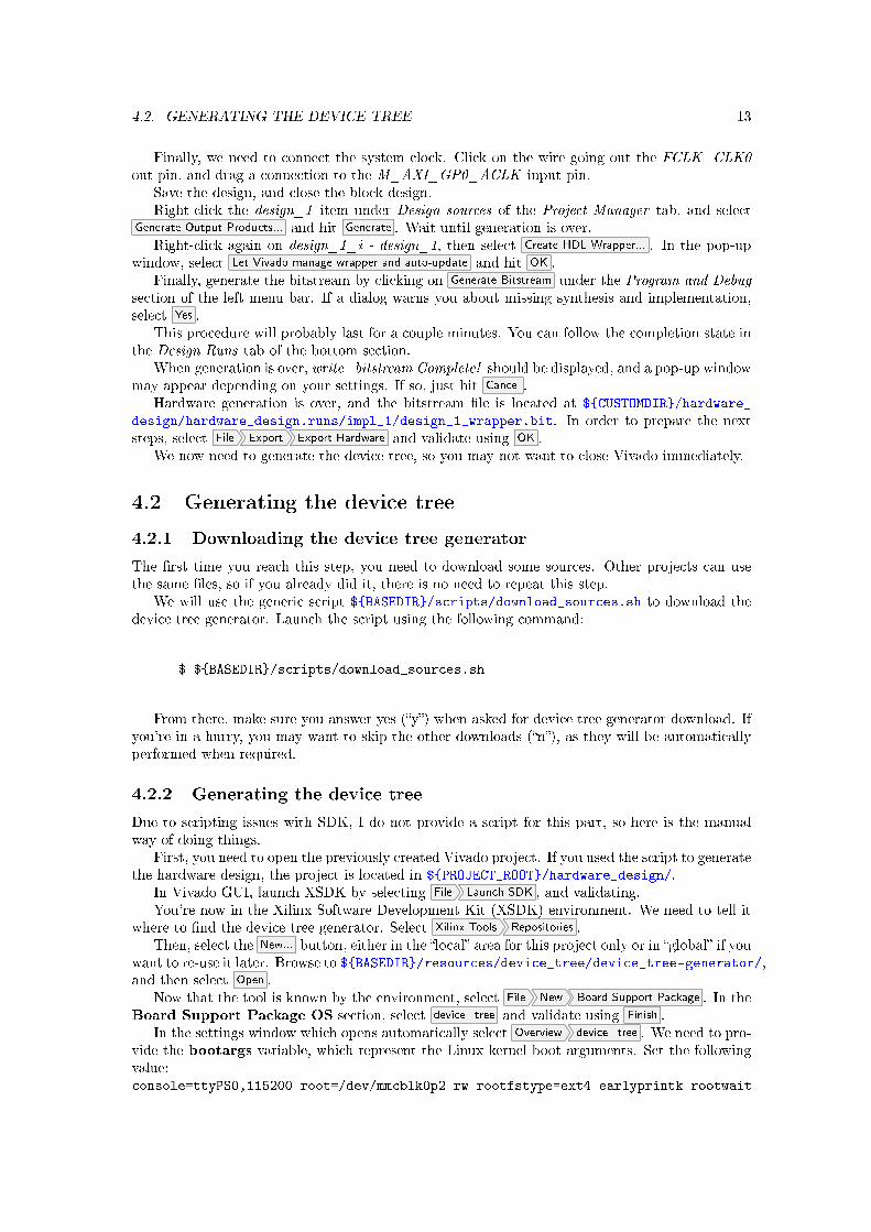
Finally, we need to connect the system clock. Click on the wire going out the FCLK_CLK0out pin, and drag a connection to the M_AXI_GP0_ACLK input pin.
Save the design, and close the block design.Right-click the design_1 item under Design sources of the Project Manager tab, and select
Generate Output Products... and hit Generate . Wait until generation is over.Right-click again on design_1_i - design_1, then select Create HDL Wrapper... . In the pop-up
window, select Let Vivado manage wrapper and auto-update and hit OK .Finally, generate the bitstream by clicking on Generate Bitstream under the Program and Debug
section of the left menu bar. If a dialog warns you about missing synthesis and implementation,select Yes .
This procedure will probably last for a couple minutes. You can follow the completion state inthe Design Runs tab of the bottom section.
When generation is over, write_bitstream Complete! should be displayed, and a pop-up windowmay appear depending on your settings. If so, just hit Cancel .
Hardware generation is over, and the bitstream �le is located at ${CUSTOMDIR}/hardware_
design/hardware_design.runs/impl_1/design_1_wrapper.bit. In order to prepare the nextsteps, select File Export Export Hardware and validate using OK .
We now need to generate the device tree, so you may not want to close Vivado immediately.
4.2 Generating the device tree
4.2.1 Downloading the device tree generator
The �rst time you reach this step, you need to download some sources. Other projects can usethe same �les, so if you already did it, there is no need to repeat this step.
We will use the generic script ${BASEDIR}/scripts/download_sources.sh to download thedevice tree generator. Launch the script using the following command:
$ ${BASEDIR}/scripts/download_sources.sh
From there, make sure you answer yes (�y�) when asked for device tree generator download. Ifyou're in a hurry, you may want to skip the other downloads (�n�), as they will be automaticallyperformed when required.
4.2.2 Generating the device tree
Due to scripting issues with SDK, I do not provide a script for this part, so here is the manualway of doing things.
First, you need to open the previously created Vivado project. If you used the script to generatethe hardware design, the project is located in ${PROJECT_ROOT}/hardware_design/.
In Vivado GUI, launch XSDK by selecting File Launch SDK , and validating.You're now in the Xilinx Software Development Kit (XSDK) environment. We need to tell it
where to �nd the device tree generator. Select Xilinx Tools Repositories .Then, select the New... button, either in the �local� area for this project only or in �global� if you
want to re-use it later. Browse to ${BASEDIR}/resources/device_tree/device_tree-generator/,and then select Open .
Now that the tool is known by the environment, select File New Board Support Package . In theBoard Support Package OS section, select device_tree and validate using Finish .
In the settings window which opens automatically select Overview device_tree . We need to pro-vide the bootargs variable, which represent the Linux kernel boot arguments. Set the followingvalue:console=ttyPS0,115200 root=/dev/mmcblk0p2 rw rootfstype=ext4 earlyprintk rootwait
14 CHAPTER 4. HARDWARE LAYOUT AND LOW-LEVEL SOFTWARE
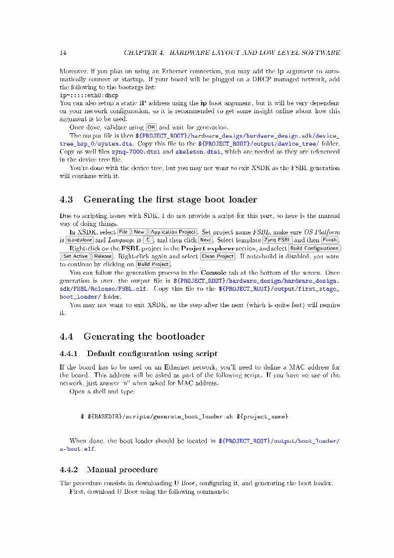
Moreover, if you plan on using an Ethernet connection, you may add the ip argument to auto-matically connect at startup. If your board will be plugged on a DHCP-managed network, addthe following to the bootargs list:ip=:::::eth0:dhcp
You can also setup a static IP address using the ip boot argument, but it will be very dependenton your network con�guration, so it is recommended to get some insight online about how thisargument is to be used.
Once done, validate using OK and wait for generation.
The output �le is then ${PROJECT_ROOT}/hardware_design/hardware_design.sdk/device_
tree_bsp_0/system.dts. Copy this �le to the ${PROJECT_ROOT}/output/device_tree/ folder.Copy as well �les zynq-7000.dtsi and skeleton.dtsi, which are needed as they are referencedin the device tree �le.
You're done with the device tree, but you may not want to exit XSDK as the FSBL generationwill continue with it.
4.3 Generating the �rst stage boot loader
Due to scripting issues with SDK, I do not provide a script for this part, so here is the manualway of doing things.
In XSDK, select File New Application Project . Set project name FSBL, make sure OS Platformis standalone and Language is C , and then click Next . Select template Zynq FSBL and then Finish .
Right-click on the FSBL project in theProject explorer section, and select Build Con�gurations
Set Active Release . Right-click again and select Clean Project . If auto-build is disabled, you wantto continue by clicking on Build Project .
You can follow the generation process in the Console tab at the bottom of the screen. Oncegeneration is over, the output �le is ${PROJECT_ROOT}/hardware_design/hardware_design.
sdk/FSBL/Release/FSBL.elf. Copy this �le to the ${PROJECT_ROOT}/output/first_stage_
boot_loader/ folder.
You may not want to exit XSDK, as the step after the next (which is quite fast) will requireit.
4.4 Generating the bootloader
4.4.1 Default con�guration using script
If the board has to be used on an Ethernet network, you'll need to de�ne a MAC address forthe board. This address will be asked as part of the following script. If you have no use of thenetwork, just answer �n� when asked for MAC address.
Open a shell and type:
$ ${BASEDIR}/scripts/generate_boot_loader.sh ${project_name}
When done, the boot loader should be located in ${PROJECT_ROOT}/output/boot_loader/
u-boot.elf.
4.4.2 Manual procedure
The procedure consists in downloading U-Boot, con�guring it, and generating the boot loader.
First, download U-Boot using the following commands:
4.5. GENERATING THE BINARY FILE 15
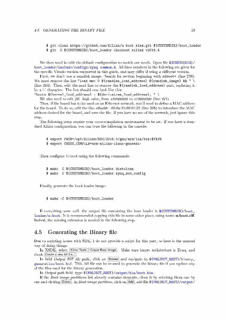
$ git clone https://github.com/Xilinx/u-boot-xlnx.git ${CUSTOMDIR}/boot_loader
$ git -C ${CUSTOMDIR}/boot_loader checkout xilinx-v2016.4
We then need to edit the default con�guration to match our needs. Open �le ${CUSTOMDIR}/boot_loader/include/configs/zynq-common.h. All lines numbers in the following are given forthe speci�c Vivado version supported in this guide, and may di�er if using a di�erent version.
First, we don't use a ramdisk image. Search for section beginning with sdboot= (line 259).We must remove the line "load mmc 0 ${ramdisk_load_address} ${ramdisk_image} && " \
(line 264). Then, edit the next line to remove the ${ramdisk_load_address} part, replacing itby a `-' character. The line should now look like this:"bootm ${kernel_load_address} - ${devicetree_load_address}; " \
We also need to edit fdt_high value, from x20000000 to x19000000 (line 221).Then, if the board has to be used on an Ethernet network, you'll need to de�ne a MAC address
for the board. To do so, edit the line ethaddr=00:0a:35:00:01:22 (line 206) to introduce the MACaddress desired for the board, and save the �le. If you have no use of the network, just ignore thisstep.
The following steps require your cross-compilation environment to be set. If you have a stan-dard Xilinx con�guration, you can type the following in the console:
$ export PATH=/opt/Xilinx/SDK/2016.4/gnu/arm/lin/bin:$PATH
$ export CROSS_COMPILE=arm-xilinx-linux-gnueabi-
Then con�gure U-boot using the following commands:
$ make -C ${CUSTOMDIR}/boot_loader distclean
$ make -C ${CUSTOMDIR}/boot_loader zynq_zed_config
Finally, generate the boot loader image:
$ make -C ${CUSTOMDIR}/boot_loader
If everything went well, the output �le containing the boot loader is ${CUSTOMDIR}/boot_
loader/u-boot. It is recommended copying this �le in some other place, using name u-boot.elf.Indeed, the missing extension is needed in the following step.
4.5 Generating the Binary �le
Due to scripting issues with SDK, I do not provide a script for this part, so here is the manualway of doing things.
In XSDK, select Xilinx Tools Create Boot Image . Make sure target architecture is Zynq, andcheck Create a new bif �le... .
In �eld Output BIF �le path:, click on Browse and navigate to ${PROJECT_ROOT}/binary_
generation/boot.bif. This .bif �le can be re-used to generate the binary �le if you update anyof the �les used for the binary generation.
In Output path �eld, type ${PROJECT_ROOT}/output/bin/boot.bin.If the Boot image partitions list already contains elements, clean it by selecting them one by
one and clicking Delete . In Boot image partition, click on Add , add �le ${PROJECT_ROOT}/output/

16 CHAPTER 4. HARDWARE LAYOUT AND LOW-LEVEL SOFTWARE
first_stage_boot_loader/FSBL.elf and make sure bootloader is the partition type. Validateusing OK .
Click on Add again, and select the bitstream. If you followed this tutorial for hardwaregeneration, it should be available at ${PROJECT_ROOT}/output/hardware_design/bitstream.
bit. If not, the bitstream should be in your Vivado folder, under the <project>.runs/impl_1/folder. Make sure the partition type is data�le, and validate.
Select Add a third time, and then choose ${PROJECT_ROOT}/output/bootloader/u-boot.elf,with a data�le partition type.
Finally, select Create Image .The �le ${PROJECT_ROOT}/output/bin/boot.bin has been created.You may now exit XSDK and Vivado.
Chapter 5
Generating Linux
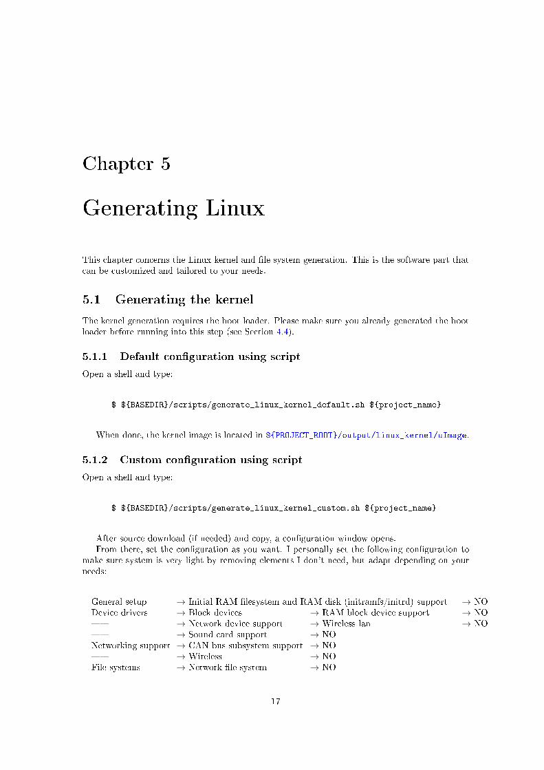
This chapter concerns the Linux kernel and �le system generation. This is the software part thatcan be customized and tailored to your needs.
5.1 Generating the kernel
The kernel generation requires the boot loader. Please make sure you already generated the bootloader before running into this step (see Section 4.4).
5.1.1 Default con�guration using script
Open a shell and type:
$ ${BASEDIR}/scripts/generate_linux_kernel_default.sh ${project_name}
When done, the kernel image is located in ${PROJECT_ROOT}/output/linux_kernel/uImage.
5.1.2 Custom con�guration using script
Open a shell and type:
$ ${BASEDIR}/scripts/generate_linux_kernel_custom.sh ${project_name}
After source download (if needed) and copy, a con�guration window opens.From there, set the con�guration as you want. I personally set the following con�guration to
make sure system is very light by removing elements I don't need, but adapt depending on yourneeds:
General setup → Initial RAM �lesystem and RAM disk (initramfs/initrd) support → NODevice drivers → Block devices → RAM block device support → NO� → Network device support → Wireless lan → NO� → Sound card support → NONetworking support → CAN bus subsystem support → NO� → Wireless → NOFile systems → Network �le system → NO
17
18 CHAPTER 5. GENERATING LINUX
Save, exit, and wait for process completion. When done, the kernel image is located in${PROJECT_ROOT}/output/linux_kernel/uImage.
5.1.3 Manual procedure
The procedure �rst consists in getting the latest kernel version, and regressing to the correctbranch, as follows:
$ git clone https://github.com/Xilinx/linux-xlnx.git ${CUSTOMDIR}/linux_kernel
$ git -C ${CUSTOMDIR}/linux_kernel checkout xilinx-v2016.4
The following steps require your cross-compilation environment to be set. If you have a stan-dard Xilinx con�guration, you can type the following in the console:
$ export PATH=/opt/Xilinx/SDK/2016.4/gnu/arm/lin/bin:$PATH
$ export CROSS_COMPILE=arm-xilinx-linux-gnueabi-
Finally, con�gure the kernel with ZedBoard defaults and launch the con�guration GUI:
$ make -C ${CUSTOMDIR}/linux_kernel distclean
$ make -C ${CUSTOMDIR}/linux_kernel ARCH=arm xilinx_zynq_defconfig
$ make -C ${CUSTOMDIR}/linux_kernel ARCH=arm xconfig
From there, set the con�guration as you want (for a con�guration example, see Section 5.1.2),save then exit the GUI.
The �nal make requires using some tools generated by the boot loader make procedure. Usethe following to make the system know where these tools are:
$ export PATH=${CUSTOMDIR}/boot_loader/tools:$PATH
Finally, build the image using the following command:
$ make -C ${CUSTOMDIR}/linux_kernel ARCH=arm UIMAGE_LOADADDR=0x8000 uImage
If everything went well, the output �le containing the kernel is ${CUSTOMDIR}/linux_kernel/arch/arm/boot/uImage.
5.2 Generating the device tree blob
You must now generate the device tree blob, which will be used by the kernel to know the systemmap. This part of the procedure requires that you already generated the device tree (see Section4.2.2) and the Linux kernel (Section 5.1).
5.3. GENERATING THE FILE SYSTEM 19
5.2.1 Default con�guration using script
Type the following in a shell:
$ ${BASEDIR}/scripts/generate_device_tree_blob.sh ${project_name}
The output �le is then ${PROJECT_ROOT}/output/dtb/devicetree.dtb.
5.2.2 Manual procedure
We assume here the device tree is located at ${CUSTOMDIR}/system.dts along with other required�les (see Section 4.2.2). Open a shell, and type
$ ${CUSTOMDIR}/linux_kernel/scripts/dtc/dtc -O dtb -I dts \$ -o ${CUSTOMDIR}/devicetree.dtb ${CUSTOMDIR}/system.dts
Output �le is then ${CUSTOMDIR}/devicetree.dtb.
5.3 Generating the �le system
5.3.1 Default con�guration using script
Open a shell and type:
$ ${BASEDIR}/scripts/generate_file_system_default.sh ${project_name}
When done, the generated �le system is located in ${PROJECT_ROOT}/output/file_system/
rootfs.ext4.
5.3.2 Custom con�guration using script
Open a shell and type:
$ ${BASEDIR}/scripts/generate_file_system_custom.sh ${project_name}
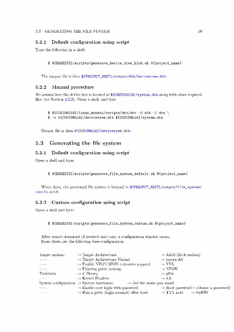
After source download (if needed) and copy, a con�guration window opens.From there, set the following base con�guration:
Target options → Target Architecture → ARM (little endian)� → Target Architecture Variant → cortex-A9� → Enable NEON SIMD extension support → YES� → Floating point strategy → NEONToolchain → C library → glibc� → Kernel Headers → 4.6System con�guration → System hostname: → (set the name you want)� → Enable root login with password → Root password→ (choose a password)� → Run a getty (login prompt) after boot → TTY port → ttyPS0
20 CHAPTER 5. GENERATING LINUX
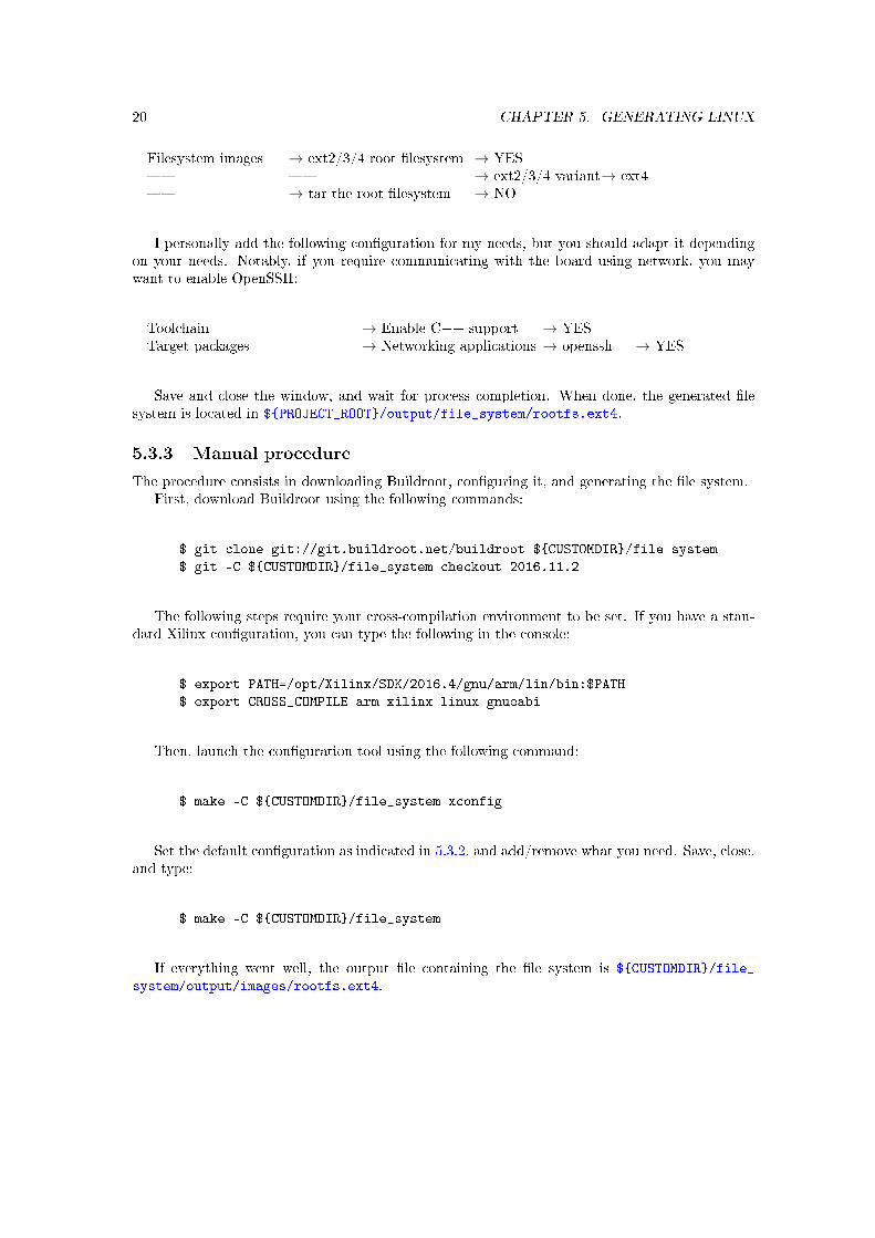
Filesystem images → ext2/3/4 root �lesystem → YES� � → ext2/3/4 variant→ ext4� → tar the root �lesystem → NO
I personally add the following con�guration for my needs, but you should adapt it dependingon your needs. Notably, if you require communicating with the board using network, you maywant to enable OpenSSH:
Toolchain → Enable C++ support → YESTarget packages → Networking applications → openssh → YES
Save and close the window, and wait for process completion. When done, the generated �lesystem is located in ${PROJECT_ROOT}/output/file_system/rootfs.ext4.
5.3.3 Manual procedure
The procedure consists in downloading Buildroot, con�guring it, and generating the �le system.First, download Buildroot using the following commands:
$ git clone git://git.buildroot.net/buildroot ${CUSTOMDIR}/file_system
$ git -C ${CUSTOMDIR}/file_system checkout 2016.11.2
The following steps require your cross-compilation environment to be set. If you have a stan-dard Xilinx con�guration, you can type the following in the console:
$ export PATH=/opt/Xilinx/SDK/2016.4/gnu/arm/lin/bin:$PATH
$ export CROSS_COMPILE=arm-xilinx-linux-gnueabi-
Then, launch the con�guration tool using the following command:
$ make -C ${CUSTOMDIR}/file_system xconfig
Set the default con�guration as indicated in 5.3.2, and add/remove what you need. Save, close,and type:
$ make -C ${CUSTOMDIR}/file_system
If everything went well, the output �le containing the �le system is ${CUSTOMDIR}/file_
system/output/images/rootfs.ext4.
Chapter 6
Preparing the board
SAVE ALL DATA CONTAINED ON THE SD CARD BEFORE PROCEEDING.THE OPERATION DEPICTED HERE WILL CAUSE ALL DATA ON THE SD
CARD TO BE LOST.
For the following, you must �rst know what is the driver �le representing your SD card. Thisis highly con�guration-dependent so we cannot provide a default value. If you don't know thevalue for your computer, you can plug the card in and use a disk utility to check your local disksand identify your reader.
6.1 Partitioning the SD card
If your SD card never has never been partitioned, you'll need to prepare it �rst. If you alreadypartitioned the card as part of this tutorial, you can skip this section.
As a scripted way of partitioning the card could damage your computer if wrong values areprovided for drive driver, we rather provide here a manual way of doing it.
Anyway, beware that you select the right drive in the following procedure!Launch GParted, and select the entry matching your SD card from the jumplist. First
unmount all partitions on your card (right click then Unmount ). Then, select menu Device
Create Partition Table... , make sure MS-DOS type is selected and select Apply.
Right-click on the empty space, select New , choose a fat32 �le system, a size of 1024 MiB andselect Add . Right-click again on the empty space, select New , choose an ext4 �le system, enterlinux_fs as the label and select Add .
Select Apply All Operations and validate using Apply . When done, exit GParted, remove the SDcard from reader, and then plug it in again before next step.
6.2 Copying the �le system on the card
6.2.1 Using the script
To use the script, �rst make sure the $SDMOUNTDIR variable in the ${BASEDIR}/scripts/
user-config/environment.sh is correctly set, representing your SD card mount point.
Open a shell and type:
$ sudo ${BASEDIR}/scripts/copy_file_system_to_memory_card.sh ${project_name}
21
22 CHAPTER 6. PREPARING THE BOARD
6.2.2 Manually
In the following, we assume the mounting point of the Linux partition of your SD card is${SDLINUXMOUNT}/, and that directory /mnt/ is empty and can be used for temporary mount.Moreover, we assume the generated �le system is ${CUSTOMDIR}/rootfs.ext4.
We �rst need to temporarily mount the generated �le system as follows:
$ sudo mount -t ext4 -o loop ${CUSTOMDIR}/rootfs.ext4 /mnt
Then we do the copy:
$ sudo cp -rf /mnt/* ${SDLINUXMOUNT}
Finally, we unmount the temporary mount point as follows:
$ sudo umount -l /mnt
6.3 Copying the system �les
Finally, open the 1 GiB fat32 partition of the SD card, and copy the following �les onto it:${PROJECT_ROOT}/output/bin/boot.bin, ${PROJECT_ROOT}/output/dtb/devicetree.dtb and${PROJECT_ROOT}/output/linux_kernel/uImage.
You can now eject the SD card.
Chapter 7
Working on the board
7.1 Hardware con�guration
Before booting, the board jumpers must be in the following position:
• JP7: SIG ⇔ GND
• JP8: SIG ⇔ GND
• JP9: 3V3 ⇔ SIG
• JP10: 3V3 ⇔ SIG
• JP11: SIG ⇔ GND
7.2 On the �rst boot
Plug the SD card onto the ZedBoard. Connect the MiniUSB cable to the USB UART port, andplug it to your computer. Open a terminal on your computer (115200 bauds, 8 bits, no parity),then start the board.
If you obtain a prompt indicating zynq-uboot>, type in boot and validate. If the prompt asksyou for a login, you're already booted.
Login using account root, then enter the password you choose. If you used the default con�g-uration script to generate the �le system, the default password is root.
7.2.1 SSH con�guration
If you de�ned no root password, the �rst thing to do is to set one as OpenSSH requires one. Type:
$ passwd
Then enter a password twice.We then require a few tricks to allow SSH connection as root. If you only require to connect
as a standard user, the following is not required.To allow root connection using SSH, type:
$ vi /etc/ssh/sshd_config
23
24 CHAPTER 7. WORKING ON THE BOARD
Navigate down using the arrows until you �nd the following line:#PermitRootLogin prohibit-password
Press inser to switch to edition mode, and change the line for:PermitRootLogin yes
Then press escape and type :wq then return to save �le.If you de�ned no password when generating the �le system, but added it manually using the
passwd command, this is not over! When connecting using OpenSSH, you'll always be told yourpassword to be expired. To solve that, do the following:
$ vi /etc/shadow
The �rst line should look like that: root:[...]:0:0:[...] We need to change the �rst �0�to anything else, e.g. to a �10�, to look like that: root:[...]:10:0:[...] Press inser, move tothe �0�, and press �1� to change �0� to �10�. Press escape then type :wq then return.
Your Linux is now OK for a SSH connection.To make sure modi�cations are written to the SD card, and depending on your needs, type:
$ reboot
Or:
$ poweroff
Remember to always use the poweroff command before turning o� the board, as Linux usesa bu�er which must be �ushed before powering o�.
You're now ready to use an Embedded Linux environment on your ZedBoard.
7.3 Using Xilinx SDK to create an application
If required, you can use Xilinx SDK to create an application for your platform using cross-compilation. To do so, re-open th SDK project you used to generate the software �les (seeSection 4.2.2 for how to open it).
Select File New Application Project , enter a name, set OS Platform to linux, and click Next .Choose either an empty application or a Hello World project.
It seems there can be an incorrect con�guration of the tool used to generate the executable.To check it, right-click on the application project you created, and select C/C++ Build Settings .Then, select ARM v7 Linux gcc assembler, and check that the gcc utility name is arm-xilinx-linux-gnueabi-gcc. If not, change it to match that name, and do the same for items ARM v7 Linuxgcc compiler and ARM v7 Linux gcc linker. Also change ARM v7 Linux Print Size command toarm-xilinx-linux-gnueabi-size.
When done, try a very simple application such as the Hello World sample by downloading itto the target, e.g. using sftp if you con�gured a SSH connection, or by manually copying it to the�le system by plugging the SD card to the host computer.
That's all, folks!