installing and connecting the router - cisco · installing and connecting the router ... correct...
TRANSCRIPT
OL-19084-02
C H A P T E R 4
Installing and Connecting the RouterCisco 1900 series routers are normally shipped with a complement of components that can be upgraded or replaced to expand and enhance the router’s functionality. These components either are inserted internally into the router or are plugged into slots in the router chassis.
This chapter tells how to physically set up Cisco 1900 series integrated services routers.
• About Modules, page 4-1
• Safety Warnings, page 4-2
• Setting Up the Chassis, page 4-3
• Installing the Chassis Ground Connection, page 4-9
• Connecting WAN and LAN Cables, page 4-11
• Connecting to a Console Terminal or Modem, page 4-14
• Installing the Cisco Microsoft Windows USB Device Driver, page 4-17
• Uninstalling the Cisco USB Driver, page 4-19
• Connecting to the Auxiliary Port, page 4-20
• Connecting Power, page 4-21
About Modules• Internal Modules, page 4-1
• Plug-In Modules, page 4-2
Internal Modules
Note The Cisco model 1905 and Cisco 1921 have no user accessible internal modules.
The router’s internal components include the following:
• DRAM
• Internal services module (ISM)
4-1Cisco 1900 Series Hardware Installation

Chapter 4 Installing and Connecting the Router Safety Warnings
If you need to remove or upgrade either of these items, follow the procedures given in Installing and Upgrading Internal Modules and FRUs in Cisco 1900 Series ISRs.
Plug-In ModulesThe following components plug into the router chassis:
• WAN interface cards (WICs)
• Voice/WAN interface cards (VWICs), data mode only
• High-speed WICs (HWICs)
• Enhanced High-speed WICs (EHWICs)
• Compact Flash memory card
If you need to remove or install WICs, VWICs, HWICs, or EHWICs follow the procedures in the Installing Cisco Interface Cards in Cisco Access Routers. If you need to remove or upgrade the Compact Flash memory card (1940 series only), follow the procedure in Installing and Upgrading Internal Modules and FRUs in Cisco 1900 Series ISRs.
Safety Warnings
Note To see translations of the warnings that appear in this publication, refer to the Regulatory Compliance and Safety Information for Cisco 1900 Series Routers document that accompanies your router.
Warning IMPORTANT SAFETY INSTRUCTIONS
This warning symbol means danger. You are in a situation that could cause bodily injury. Before you work on any equipment, be aware of the hazards involved with electrical circuitry and be familiar with standard practices for preventing accidents. Use the statement number provided at the end of each warning to locate its translation in the translated safety warnings that accompanied this device. Statement 1071
SAVE THESE INSTRUCTIONS
Warning No user-serviceable parts inside. Do not open. Statement 1073
Warning Read the installation instructions before you connect the system to its power source. Statement 1004
Warning Only trained and qualified personnel should be allowed to install, replace, or service this equipment. Statement 1030
4-2Cisco 1900 Series Hardware Installation
OL-19084-02

Chapter 4 Installing and Connecting the Router Setting Up the Chassis
Warning Ultimate disposal of this product should be handled according to all national laws and regulations. Statement 1040
Safety Warnings for Finland, Norway and SwedenWarning statement 1017 applies to the countries of Finland, Norway, and Sweden.
Warning This unit is intended for installation in restricted access areas. A restricted access area can be accessed only through the use of a special tool, lock and key, or other means of security. Statement 1017
Setting Up the ChassisThe Cisco 1900 series router can be installed on a desktop, and can also be mounted on a wall. Select the setup that best meets the needs of your network. These setups are described in the following sections:
• Chassis Airflow Diagram, page 4-3
• Setting the Chassis on a Desktop, page 4-4
• Chassis Grounding, page 4-4
• Wall-Mounting the Chassis, page 4-4
• Rack-Mounting the Chassis, page 4-7
Caution The front panel bezel must not be removed from the Cisco 1900 series router. It is part of the product's enclosure, and must be left in place to prevent damage from foreign parts entering the router, to provide a shield from internal electromagnetic interference (EMI), and to direct the flow of cooling air properly through the chassis.
Chassis Airflow DiagramFigure 4-1 shows the airflow through and around the Cisco 1905 and Cisco 1921 chassis.
Figure 4-1 Cisco 1905 and Cisco 1921 Chassis Airflow
Cisco 1900 Series
SYS ACT POE
2537
16
4-3Cisco 1900 Series Hardware Installation
OL-19084-02

Chapter 4 Installing and Connecting the Router Setting Up the Chassis
Figure 4-2 shows the airflow through and around the Cisco 1940 series chassis.
Figure 4-2 Cisco 1940 Series Chassis Airflow
Setting the Chassis on a DesktopYou can place Cisco 1900 series routers on a desktop or shelf. The Cisco 1900 series router is shipped with the rubber feet attached to the chassis to protect the desktop.
Warning To prevent personal injury or damage to the chassis, never attempt to lift or tilt the chassis using the handles on modules (such as power supplies, fans, or cards); these types of handles are not designed to support the weight of the unit. Statement 1032
Caution Do not place anything on top of the router that weighs more than 10 pounds (4.5 kilograms). Excessive weight on top of the router could damage the chassis.
Chassis GroundingAfter the router has been installed, you must connect the chassis to a reliable earth ground. For the chassis ground connection procedure, see the “Installing the Chassis Ground Connection” section on page 4-9.
Wall-Mounting the Chassis
Warning If your Cisco 1900 series router uses a DC power source, you cannot wall-mount it.
Warning Read the wall-mounting instructions carefully before beginning installation. Failure to use the correct hardware or to follow the correct procedures could result in a hazardous situation to people and damage to the system. Statement 378
DO NOT REMOVE DURING
NETWORK OPERATION
DO NOT REMOVE DURING
NETWORK OPERATION
2513
69
4-4Cisco 1900 Series Hardware Installation
OL-19084-02

Chapter 4 Installing and Connecting the Router Setting Up the Chassis
The Cisco 1900 series router can be wall-mounted by using two number six, 3/4-inch screws and the mounting features on the bottom of the router. You must provide the screws. We recommend using pan-head or round-head screws.
Caution The screws must go into a wall stud (wood) or a wall anchor of the appropriate type for the wall. Screws into drywall are not sufficient to mount the router.
Figure 4-3 shows the wall-mounting features on the Cisco 1905 and Cisco 1921 routers.
Figure 4-3 Wall-Mounting Features on the Cisco 1905 and Cisco 1921 Routers
1 Wall screws 2 8 inches (20.3 cm)
3 Chassis mounting holes (on bottom) 4 Router chassis
5 Mounting surface
2537
11
5
4
3
2
1
1
4-5Cisco 1900 Series Hardware Installation
OL-19084-02

Chapter 4 Installing and Connecting the Router Setting Up the Chassis
Figure 4-4 shows the wall-mounting features on the Cisco 1941 series routers.
Figure 4-4 Wall-Mounting Features on the Cisco 1941 Router
To mount the router on a wall or other surface, follow these steps:
Procedure
Step 1 Install the two screws 5 inches (12.7 centimeters) horizontally apart on a wall or other vertical surface.
The screws should protrude 0.25 inch (0.6 centimeter) from the surface of the wall.
Caution If you install the screws in drywall, use hollow-wall anchors (1/8 inch by 5/16 inch) to secure the screws. If the screws are not properly anchored, the strain of the cables connected to the router back panel could pull the router from the wall.
Step 2 Remove the rubber feet from the router.
1 Wall screws 2 5 inches (12.7 cm)
3 Chassis mounting holes (on bottom) 4 Router chassis
5 Mounting surface25
1360S
L
L
CO
NS
OL
E AU
X
SL
US
B 1G
E 0/1
GE0/0
0E
NE
ND
O N
OT R
EMO
VE DU
RIN
GN
ETWO
RKIN
G O
PERATIO
NC
F 2
CF
1D
O N
OT R
EMO
VE DU
RIN
GN
ETWO
RKIN
G O
PERATIO
NIS
M/W
LA
N
1 54
3
2
4-6Cisco 1900 Series Hardware Installation
OL-19084-02

Chapter 4 Installing and Connecting the Router Setting Up the Chassis
Step 3 Hang the router on the screws. This is the appropriate orientation for safe use. (See Figure 4-3 and Figure 4-4.)
Rack-Mounting the Chassis
Warning Read the wall-mounting instructions carefully before beginning installation. Failure to use the correct hardware or to follow the correct procedures could result in a hazardous situation to people and damage to the system. Statement 378
Warning Stability hazard. The rack stabilizing mechanism must be in place, or the rack must be bolted to the floor before you slide the unit out for servicing. Failure to stabilize the rack can cause the rack to tip over. Statement 1048
The Cisco 1900 series router can be installed in a 19-inch EIA rack. Mounting brackets allow installing in either a front and rear facing position.
You can mount the router in the following ways:
• Front mounting—Brackets attached at the front of the chassis with the front panel facing forward.
• Back mounting—Brackets attached at the back of the chassis with the back panel facing forward.
Note The rubber feet need to be removed for rack mounting.
Attaching Rack-Mount Brackets to Cisco 1900 Series Routers
Use four of the supplied number-8 Phillips screws to attach the long side of each bracket to the router. Figure 4-5 shows how to attach the brackets to the sides of the router with the front panel forward.
Depending on your router model and if you decide to front mount or back mount, attach the brackets according to one of the following figures:
• Figure 4-5 on page 4-8, Bracket Installation for Front Mounting the Cisco 1905 and Cisco 1921 ISRs
• Figure 4-6 on page 4-8, Bracket Installation for Back Mounting the Cisco 1905 and Cisco 1921 ISRs
• Figure 4-7 on page 4-8, Bracket Installation for Front Mounting the Cisco 1940 Series ISR
• Figure 4-8 on page 4-9, Bracket Installation for Back Mounting the Cisco 1940 Series ISR
4-7Cisco 1900 Series Hardware Installation
OL-19084-02

Chapter 4 Installing and Connecting the Router Setting Up the Chassis
Figure 4-5 Bracket Installation for Front Mounting the Cisco 1905 and Cisco 1921 ISRs
Note The screw size should be torqued to a value of 8.0-10.0 inch pounds for 6-32 screws.
Figure 4-6 shows how to attach the brackets to the sides of the router with the back panel forward.
Figure 4-6 Bracket Installation for Back Mounting the Cisco 1905 and Cisco 1921 ISRs
Figure 4-7 shows how to attach the brackets to the sides of the router with the front panel forward.
Note The screw size should be torqued to a value of 15.0-18.0 inch pounds for 8-32 screws.
Figure 4-7 Bracket Installation for Front Mounting the Cisco 1940 Series ISR
2537
12
Cisco 2900 Series
SYS ACT POE
2537
13
Cisco 1900 Series
SYS ACT POE
DO NOT REMOVE DURINGNETWORK OPERATION DO NOT REMOVE DURINGNETWORK OPERATION
2509
98
4-8Cisco 1900 Series Hardware Installation
OL-19084-02

Chapter 4 Installing and Connecting the Router Installing the Chassis Ground Connection
Figure 4-8 shows how to attach the brackets to the sides of the router with the back panel forward.
Figure 4-8 Bracket Installation for Back Mounting the Cisco 1940 Series ISR
Figure 4-9 shows how to attach the brackets to the rack.
Figure 4-9 Bracket Installation to Rack
Note The screw size should be 10-32 or 12-32 for mounting the rack.
Installing the Chassis Ground Connection
Warning This equipment must be grounded. Never defeat the ground conductor or operate the equipment in the absence of a suitably installed ground conductor. Contact the appropriate electrical inspection authority or an electrician if you are uncertain that suitable grounding is available. Statement 1024
DO NOT REMOVE DURINGNETWORK OPERATION DO NOT REMOVE DURINGNETWORK OPERATION
2509
97
DO NOT REMOVE DURINGNETWORK OPERATION DO NOT REMOVE DURINGNETWORK OPERATION
2509
99
1
4-9Cisco 1900 Series Hardware Installation
OL-19084-02

Chapter 4 Installing and Connecting the Router Installing the Chassis Ground Connection
Warning This equipment needs to be grounded. Use a green and yellow 12 to 14 AWG ground wire to connect the host to earth ground during normal use. Statement 242
You must connect the chassis to a reliable earth ground, using a ground lug and size 14 AWG (2 mm2) wire.
To install the ground connection for a Cisco 1900 series router, follow these steps.
Procedure
Step 1 Strip one end of the ground wire to expose approximately 0.75 in. (20 mm) of conductor.
Step 2 Crimp the 14 AWG green ground wire to a UL Listed/CSA certified ring terminal that is suitably sized for the number 6 ground screw provided on the rear panel of the router. The crimping tool should be one that is recommended by the ring lug terminal manufacturer.
Step 3 Attach the ring terminal to the chassis. The attachment points are shown in Figure 4-10 and Figure 4-11. Use a number 2 Phillips screwdriver and the screw supplied with the ground lug. Tighten the screw to a torque of 8 to 10 in-lb. (0.9 to 1.1 N-m).
Figure 4-10 Chassis Ground Connection on the Cisco 1905 and Cisco 1921 Routers
SL
CONSOLE
AUX
GE 0/0
GE 0/1
POE
Cisco 1905
RESETS
L
BAUD
48VDC 1.67A
100-240 V~ 50-60 Hz 1A
2537
14
4-10Cisco 1900 Series Hardware Installation
OL-19084-02

Chapter 4 Installing and Connecting the Router Connecting WAN and LAN Cables
Figure 4-11 Chassis Ground Connection on the Cisco 1941 Router
Step 4 Connect the other end of the ground wire to a known good electrical ground point. Consult with a licensed electrician if you have any questions about the suitability of the ground connection.
Connecting WAN and LAN Cables• Safety Messages, page 4-11
• Ports and Cabling, page 4-13
• Connection Procedures and Precautions, page 4-14
Note You can order additional network connection cables and transceivers from Cisco. For ordering information, contact Cisco customer service. For cable pinouts, refer to Cisco Modular Access Router Cable Specifications.
Safety Messages
Warning Do not work on the system, or connect or disconnect cables during periods of lightning activity. Statement 1001
Warning Voice over IP (VoIP) service and the emergency calling service do not function if power fails or is disrupted. After power is restored, you might have to reset or reconfigure equipment to regain access to VoIP and the emergency calling service. In the USA, this emergency number is 911. You need to be aware of the emergency number in your country. Statement 361
GE 0/1
CONSOLE
ENEN
LS
USB
1
GE0/0
0
2513
59
4-11Cisco 1900 Series Hardware Installation
OL-19084-02

Chapter 4 Installing and Connecting the Router Connecting WAN and LAN Cables
Warning Do not use this product near water; for example, near a bath tub, wash bowl, kitchen sink or laundry tub, in a wet basement, or near a swimming pool. Statement 1035
Warning Never install telephone jacks in wet locations unless the jack is specifically designed for wet locations. Statement 1036
Warning Avoid using a telephone (other than a cordless type) during an electrical storm. There may be a remote risk of electric shock from lightning. Statement 1038
Warning To report a gas leak, do not use a telephone in the vicinity of the leak. Statement 1039
Warning To avoid electric shock, do not connect safety extra-low voltage (SELV) circuits to telephone-network voltage (TNV) circuits. LAN ports contain SELV circuits, and WAN ports contain TNV circuits. Some LAN and WAN ports both use RJ-45 connectors. Use caution when connecting cables. Statement 1021
Warning Hazardous network voltages are present in WAN ports regardless of whether power to the router is OFF or ON. To avoid electric shock, use caution when working near WAN ports. When detaching cables, detach the end away from the router first. Statement 1026
Warning Blank faceplates and cover panels serve three important functions: they prevent exposure to hazardous voltages and currents inside the chassis; they contain electromagnetic interference (EMI) that might disrupt other equipment; and they direct the flow of cooling air through the chassis. Do not operate the system unless all cards, faceplates, front covers, and rear covers are in place. Statement 1029
Warning Invisible laser radiation may be emitted from disconnected fibers or connectors. Do not stare into beams or view directly with optical instruments. Statement 1051
Warning Do not locate the antenna near overhead power lines or other electric light or power circuits, or where it can come into contact with such circuits. When installing the antenna, take extreme care not to come into contact with such circuits, because they may cause serious injury or death. For proper installation and grounding of the antenna, please refer to national and local codes (for example, U.S.:NFPA 70, National Electrical Code, Article 810, Canada: Canadian Electrical Code, Section 54). Statement 1052
Warning Class I (CDRH) and Class 1M (IEC) laser products. Statement 1055
4-12Cisco 1900 Series Hardware Installation
OL-19084-02

Chapter 4 Installing and Connecting the Router Connecting WAN and LAN Cables
Warning Invisible laser radiation may be emitted from the end of the unterminated fiber cable or connector. Do not view directly with optical instruments. Viewing the laser output with certain optical instruments (for example, eye loupes, magnifiers, and microscopes) within a distance of 100 mm may pose an eye hazard. Statement 1056
Warning Before opening the unit, disconnect the telephone-network cables to avoid contact with telephone-network voltages. Statement 1041
Warning This equipment contains a ring signal generator (ringer), which is a source of hazardous voltage. Do not touch the RJ-11 (phone) port wires (conductors), the conductors of a cable connected to the RJ-11 port, or the associated circuit-board when the ringer is active. The ringer is activated by an incoming call. Statement 1042
Ports and CablingTable 4-1 summarizes some typical WAN and LAN connections for Cisco 1900 series routers. These connections are also described in detail in Cisco Modular Access Router Cable Specifications.
Table 4-1 WAN and LAN Connections
Port or Connection Port Type, Color1 Connected to: Cable
Gigabit Ethernet (GE)
RJ-45, yellow Ethernet switch or hub. Crossover to connect to a router
Straight-through to connect to a switch
T1/E1 WAN RJ-48C T1 or E1 network or CSU/DSU.
RJ-48 T1/E1 straight-through (Crossover to connect to a PBX or any other equipment)
Cisco serial (1T) 60-pin D-sub, blue CSU/DSU and serialnetwork or equipment.
Cisco serial transition cable that matches the signaling protocol (EIA/TIA-232, EIA/TIA-449, V.35, X.21, or EIA/TIA-530) and the serial port operating mode (DTE or DCE).
Refer to Cisco Modular Access Router Cable Specifications for information about selecting these cables.
Cisco Smart serial (2T)
Cisco Smart compact connector, blue
CSU/DSU and serialnetwork or equipment.
For WIC-2T and WIC-2A/S only.
4-13Cisco 1900 Series Hardware Installation
OL-19084-02

Chapter 4 Installing and Connecting the Router Connecting to a Console Terminal or Modem
Connection Procedures and PrecautionsConnect each WAN and LAN cable to the appropriate connector on the chassis or interface card.
• Position the cables carefully, so that they do not put strain on the connectors.
• Organize the cables in bundles so that cables do not intertwine.
• Inspect the cables to make sure that the routing and bend radiuses are satisfactory. Reposition the cables, if necessary.
• Install cable ties in accordance with your site requirements.
For cable pinouts, refer to Cisco Modular Access Router Cable Specifications.
Connecting to a Console Terminal or ModemYour router has asynchronous serial, USB, console, and auxiliary ports. These ports provide administrative access to your router either locally (with a console terminal or PC) or remotely (with a modem).
The following cables and adapters may be used for connecting your router to a console terminal, PC, or modem:
• USB console cable—USB 5-pin mini Type-B to USB Type-A. See the “USB Serial Console” section on page 3-2 for port details and the “Specifications” section on page 1-13.
• Console cable— EIA RJ-45 to DB-9
• Modem adapter—DB-9 to DB-25
Note The first time a Windows-based PC is connected to the router, a USB device driver must be installed. See the “Installing the Cisco Microsoft Windows USB Device Driver” section on page 4-17.
DSL RJ-11C/RJ-14C Network demarcationdevice for service provider’sDSL interface.
RJ-11 straight-through for 2-wire
RJ-14 straight-through for 4-wire
BRI S/T WAN (external NT12)
RJ-45, orange NT1 device or PINX3 RJ-45 straight-through
BRI U WAN (built-in NT1)
RJ-49C/CA-A11, orange
ISDN network RJ-49 straight-through
Analog modem RJ-11 PSTN RJ-11 straight-through
56/64-kbps CSU/DSU
8-pin modular RJ-48S interface. RJ-48 straight-through.
1. The color codes are specific to cables shipped by Cisco
2. NT1 = Network Termination 1
3. PINX = Private integrated network exchange
Table 4-1 WAN and LAN Connections (continued)
Port or Connection Port Type, Color1 Connected to: Cable
4-14Cisco 1900 Series Hardware Installation
OL-19084-02

Chapter 4 Installing and Connecting the Router Connecting to a Console Terminal or Modem
This section describes how to connect a console terminal or PC to the console port and how to connect a modem to the auxiliary port.
• Connecting to the Console Port with Microsoft Windows, page 4-15
• Connecting to the Console Port with Mac OS X, page 4-16
• Connecting to the Console Port with Linux, page 4-17
Connecting to the Console Port with Microsoft WindowsTo configure the router through the Cisco IOS command-line interface (CLI), you must connect the router console port to a terminal or PC. See the “Console and Auxiliary Port Considerations” section on page 3-1.
A Microsoft Windows PC must have HyperTerminal or similar terminal emulation software installed. The software should be configured with the following parameters: 9600 baud, 8 data bits, no parity, 1 stop bit, and no flow control. Refer to the Cisco 3900 Series, 2900 Series, and 1900 Series Software Configuration Guide for detailed information about using Cisco IOS software for configuring the router.
To connect the router to a terminal or PC, follow these steps:
Procedure
Step 1 Connect the end of the console cable with the RJ-45 connector to the light blue console port on the router, or USB 5-pin mini Type-B to the USB console port as shown in Figure 4-12. If connecting the USB port for the first time on a Windows based PC, you must install the Windows USB driver. See the “Installing the Cisco Microsoft Windows USB Device Driver” section on page 4-17.
Note You must use either the USB port or the RJ-45 port, but not both simultaneously. See the “USB Serial Console” section on page 3-2. When the USB port is used it takes priority over the RJ-45 EIA port.
4-15Cisco 1900 Series Hardware Installation
OL-19084-02

Chapter 4 Installing and Connecting the Router Connecting to a Console Terminal or Modem
Figure 4-12 Connecting the Console Cable to the Router
Step 2 Connect the end of the cable with the DB-9 connector (or USB Type-A) to the terminal or PC. If your terminal or PC has a console port that does not accommodate a DB-9 connector, you must provide an appropriate adapter for that port.
Step 3 To communicate with the router, start a terminal emulator application.
Connecting to the Console Port with Mac OS XThis procedure shows how to connect a Mac OS X system USB port to the console using the built in OS X Terminal utility.
1 USB 5-pin mini Type-B console port 2 USB 5-pin mini Type-B to USB Type-A console cable
3 USB Type-A connector
DO NOT REMOVE DURINGNETWORK OPERATION DO NOT REMOVE DURINGNETWORK OPERATION GE 0/1
LS
USB
1
GE0/0
0CONSOLE
ENEN
3
12
2
2513
62
EN
4-16Cisco 1900 Series Hardware Installation
OL-19084-02

Chapter 4 Installing and Connecting the Router Installing the Cisco Microsoft Windows USB Device Driver
Procedure
Step 1 Use the Finder to go to Applications > Utilities > Terminal.
Step 2 Connect the OS X USB port to the router.
Step 3 Enter the following commands to find the OS X USB port number:
macbook:user$ cd /devmacbook:user$ ls -ltr /dev/*usb*crw-rw-rw- 1 root wheel 9, 66 Apr 1 16:46 tty.usbmodem1a21 DT-ullals-macbook:dev user$
Step 4 Connect to the USB port with the following command followed by the router USB port speed:
macbook:user$ screen /dev/tty.usbmodem1a21 9600
Step 5 To disconnect the OS X USB console from the Terminal window, enter Ctrl-a followed by Ctrl-\.
Connecting to the Console Port with LinuxThis procedure shows how to connect a Linux system USB port to the console using the built in Linux Terminal utility.
Procedure
Step 1 Open the Linux Terminal window.
Step 2 Connect the Linux USB port to the router.
Step 3 Enter the following commands to find the Linux USB port number:
root@usb-suse# cd /devroot@usb-suse /dev# ls -ltr *ACM*crw-r--r-- 1 root root 188, 0 Jan 14 18:02 ttyACM0root@usb-suse /dev#
Step 4 Connect to the USB port with the following command followed by the router USB port speed:
root@usb-suse /dev# screen /dev/ttyACM0 9600
Step 5 To disconnect the Linux USB console from the Terminal window, enter Ctrl-a followed by : then quit.
Installing the Cisco Microsoft Windows USB Device DriverThe first time a Microsoft Windows based PC is connected to the router, a USB driver must be installed.
• Installing the Cisco Microsoft Windows XP USB Driver, page 4-18
• Installing the Cisco Microsoft Windows 2000 USB Driver, page 4-18
• Installing the Cisco Microsoft Windows Vista USB Driver, page 4-18
4-17Cisco 1900 Series Hardware Installation
OL-19084-02

Chapter 4 Installing and Connecting the Router Installing the Cisco Microsoft Windows USB Device Driver
Installing the Cisco Microsoft Windows XP USB Driver
Before You Begin
• Download the driver for your router model from the Tools and Resources Download Software site, USB Console Software category, at http://www.cisco.com/cisco/software/type.html?mdfid=282977114&flowid=716
Procedure
Step 1 Unzip the file cisco_usbconsole_driver_X_X.zip (where X is a revision number).
Step 2 Double-click the file setup.exe.
Step 3 The Cisco Virtual Com InstallShield Wizard begins. Click Next.
Step 4 The Ready to Install the Program window appears, Click Install.
Step 5 The InstallShield Wizard Completed window appears. Click Finish.
Step 6 Connect the USB cable to the PC and router USB console ports. See Table 4-1 on page 4-16. The EN LED for the USB console port turns green, and within a few moments the Found New Hardware Wizard appears.
The USB console is ready for use.
Installing the Cisco Microsoft Windows 2000 USB Driver
Procedure
Step 1 Obtain the file cisco_usbconsole.zip from the Cisco.com web site and unzip it.
Step 2 Double-click the file setup.exe.
Step 3 The Cisco Virtual Com InstallShield Wizard begins. Click Next.
Step 4 The Ready to Install the Program window appears, Click Install.
Step 5 The InstallShield Wizard Completed window appears. Click Finish.
Step 6 Connect the USB cable to the PC and router USB console ports. See Table 4-1 on page 4-16. The EN LED for the USB console port turns green, and within a few moments a series of Found New Hardware Wizard windows appear.
The USB console is ready for use.
Installing the Cisco Microsoft Windows Vista USB Driver
Procedure
Step 1 Obtain the file cisco_usbconsole.zip from the Cisco.com web site and unzip it.
Step 2 Double-click the file setup.exe.
4-18Cisco 1900 Series Hardware Installation
OL-19084-02

Chapter 4 Installing and Connecting the Router Uninstalling the Cisco USB Driver
Step 3 The Cisco Virtual Com InstallShield Wizard begins. Click Next.
Step 4 The Ready to Install the Program window appears, Click Install.
Note If a User Account Control warning appears, click “Allow - I trust this program...” to proceed.
Step 5 The InstallShield Wizard Completed window appears. Click Finish.
Step 6 Connect the USB cable to the PC and router USB console ports. See Table 4-1 on page 4-16. The EN LED for the USB console port turns green, and within a few moments a pop up window stating “Installing device driver software” appears.
The USB console is ready for use.
Uninstalling the Cisco USB Driver• Uninstalling the Cisco Microsoft Windows XP and 2000 USB Driver, page 4-19
• Uninstalling the Cisco Microsoft Windows Vista USB Driver, page 4-20
Uninstalling the Cisco Microsoft Windows XP and 2000 USB DriverThese procedures show how to uninstall both the Microsoft Windows XP and 2000 USB driver. The driver can be removed using the Windows Add Remove Programs utility or the setup.exe program.
• Using the Add Remove Programs Utility, page 4-19
• Using the Setup.exe Program, page 4-19
Using the Add Remove Programs Utility
Before You Begin
Disconnect the router console terminal before uninstalling the driver.
Procedure
Step 1 Click Start > Control Panel > Add or Remove Programs.
Step 2 Scroll to Cisco Virtual Com and click Remove.
Step 3 When the Program Maintenance window appears, select the Remove radio button.
Step 4 Click Next.
Using the Setup.exe Program
Before You Begin
Disconnect the router console terminal before uninstalling the driver.
4-19Cisco 1900 Series Hardware Installation
OL-19084-02

Chapter 4 Installing and Connecting the Router Connecting to the Auxiliary Port
Procedure
Step 1 Run the setup.exe program. Click Next.
Step 2 The InstallShield Wizard for Cisco Virtual Com appears. Click Next.
Step 3 When the Program Maintenance window appears, select the Remove radio button. Click Next.
Step 4 When the Remove the Program window appears, click Remove.
Step 5 When the InstallShield Wizard Completed window appears click Finish.
Uninstalling the Cisco Microsoft Windows Vista USB Driver
Before You Begin
Disconnect the router console terminal before uninstalling the driver.
Procedure
Step 1 Run the setup.exe program. Click Next.
Step 2 The InstallShield Wizard for Cisco Virtual Com appears. Click Next.
Step 3 When the Program Maintenance window appears, select the Remove radio button.
Step 4 Click Next.
Step 5 When the Remove the Program window appears, click Remove.
Note If a User Account Control warning appears, click “Allow - I trust this program...” to proceed.
Step 6 When the InstallShield Wizard Completed window appears click Finish.
Connecting to the Auxiliary PortWhen a modem is connected to the auxiliary port, a remote user can dial in to the router and configure it. Use the light blue console cable and the DB-9-to-DB-25 connector adapter that came in the router accessory kit.
To connect a modem to the router, follow these steps.
Procedure
Step 1 Connect the RJ-45 end of the adapter cable to the black AUX port on the router. See Figure 4-13.
4-20Cisco 1900 Series Hardware Installation
OL-19084-02

Chapter 4 Installing and Connecting the Router Connecting Power
Figure 4-13 Connecting a Modem to the Router
Step 2 Connect the DB-9 end of the console cable to the DB-9 end of the modem adapter.
Step 3 Connect the DB-25 end of the modem adapter to the modem.
Step 4 Make sure that your modem and the router auxiliary port are configured for the same transmission speed (up to 115200 bps is supported) and for mode control with data carrier detect (DCD) and data terminal ready (DTR) operations.
Connecting PowerThis section explains how to connect AC or DC power to Cisco 1900 series routers. It covers the following topics:
• Connecting to AC Power, page 4-22
• Connecting to DC Power, page 4-22
Warning Read the installation instructions before connecting the system to the power source. Statement 1004
Warning Take care when connecting units to the supply circuit so that wiring is not overloaded. Statement 1018
1 Aux port (RJ-45) 3 DB-9-to-DB-25 modem adapter
2 Light blue console cable 4 Modem
DO NOT REMOVE DURINGNETWORK OPERATION DO NOT REMOVE DURINGNETWORK OPERATION GE 0/1
CONSOLE
ENEN
LS
USB
1
GE0/0
0
2513
63
2
34
CONSOLE
AUX
EN
AUX
1
4-21Cisco 1900 Series Hardware Installation
OL-19084-02

Chapter 4 Installing and Connecting the Router Connecting Power
Warning This unit might have more than one power supply connection. All connections must be removed to de-energize the unit. Statement 1028
Warning Only trained and qualified personnel should be allowed to install, replace, or service this equipment. Statement 1030
Note The installation must comply with all required electrical codes applicable at the installation site.
Connecting to AC PowerIf your router uses AC power, connect it to a 15A, 120VAC (10A, 240VAC) circuit with overcurrent protection.
Note The input voltage tolerance limits for AC power are 85 and 264 VAC.
Note This product requires surge protection to be provided as part of the building installation. To comply with the Telcordia GR-1089 NEBS standard for electromagnetic compatibility and safety, an external surge protective device (SPD) is required at the AC power service equipment.
Warning AC connected units must have a permanent ground connection in addition to the power cable ground wire. NEBS-compliant grounding satisfies this requirement. Statement 284
Warning This product requires short-circuit (overcurrent) protection, to be provided as part of the building installation. Install only in accordance with national and local wiring regulations. Statement 1045
Warning This product relies on the building’s installation for short-circuit (over current) protection. Ensure that the protective device is rated not greater than: 15A, 120VAC (10A, 240VAC). Statement 1005
Connecting to DC PowerIf your router has a DC-input power supply, follow the directions in this section for proper wiring. A router with a DC-input power supply has a terminal block for the DC power connections.
• DC Wiring Requirements for Cisco 1900 Series Routers, page 4-23
• Cisco 1900 Series Router Wiring Procedure for DC Input, page 4-23
Caution DC return is isolated from the frame. (NEBS DC-1)
4-22Cisco 1900 Series Hardware Installation
OL-19084-02

Chapter 4 Installing and Connecting the Router Connecting Power
Warning This product requires short-circuit (overcurrent) protection, to be provided as part of the building installation. Install only in accordance with national and local wiring regulations. Statement 1045
Warning This product relies on the building’s installation for short-circuit (over current) protection. Ensure that the protective device is rated not greater than: 60VDC, 20A. Statement 1005
Warning Only trained and qualified personnel should be allowed to install, replace, or service this equipment. Statement 1030
Warning Use copper conductors only. Statement 1025
DC Wiring Requirements for Cisco 1900 Series Routers
A Cisco 1921 router with a DC-input power supply requires copper wire and crimp-type terminals for the power connections. Table 4-2 summarizes the wiring requirements.
You can connect a single DC power source to either the A input or the B input. If there are dual power sources, connect one source to the A input and one source to the B input; both sources must be the same polarity and voltage.
Cisco 1900 Series Router Wiring Procedure for DC Input
To connect a router to a DC power source, perform the following steps.
Procedure
Step 1 Remove power from the DC circuit. To ensure that power is removed from the DC circuit, locate the circuit breaker for the DC circuit, switch the circuit breaker to the OFF position, and tape the circuit-breaker switch in the OFF position.
Warning Before performing any of the following procedures, ensure that power is removed from the DC circuit. Statement 1003
Warning Use copper conductors only. Statement 1025
Table 4-2 DC Wiring Requirements for Cisco 1900 Routers
DC Power InputDC Input Wire Size
Safety Ground Wire Size Wire Terminal (Lug)
Overcurrent Protection
32-60 VDC, 4A, positive or negative, single source
AWG 14 (2.0 mm2)
AWG 14 (2.0 mm2), minimum
Amp/Tyco No. 32957 20 A maximum
4-23Cisco 1900 Series Hardware Installation
OL-19084-02
Chapter 4 Installing and Connecting the Router Connecting Power
Warning Only trained and qualified personnel should be allowed to install, replace, or service this equipment. Statement 1030
Tip Secure all power cabling when installing this unit to avoid disturbing field-wiring connections.
Warning When stranded wiring is required, use approved wiring terminations, such as closed-loop or spade-type with upturned lugs. These terminations should be the appropriate size for the wires and should clamp both the insulation and conductor. Statement 1002
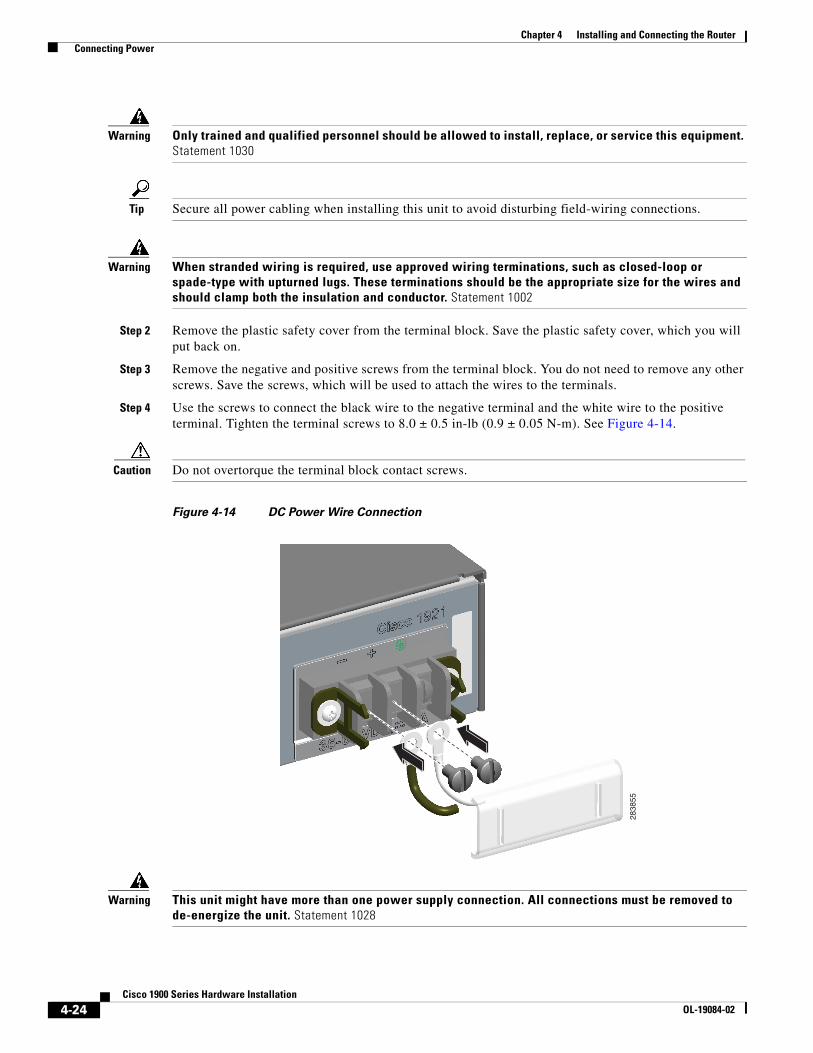
Step 2 Remove the plastic safety cover from the terminal block. Save the plastic safety cover, which you will put back on.
Step 3 Remove the negative and positive screws from the terminal block. You do not need to remove any other screws. Save the screws, which will be used to attach the wires to the terminals.
Step 4 Use the screws to connect the black wire to the negative terminal and the white wire to the positive terminal. Tighten the terminal screws to 8.0 ± 0.5 in-lb (0.9 ± 0.05 N-m). See Figure 4-14.
Caution Do not overtorque the terminal block contact screws.
Figure 4-14 DC Power Wire Connection
Warning This unit might have more than one power supply connection. All connections must be removed to de-energize the unit. Statement 1028
283855
4-24Cisco 1900 Series Hardware Installation
OL-19084-02

Chapter 4 Installing and Connecting the Router Connecting Power
Warning The illustration shows the DC power supply terminal block. Wire the DC power supply as illustrated. The proper wiring sequence is ground to ground, positive to positive, and negative to negative. The ground wire should always be connected first and disconnected last. Statement 239
Warning An exposed wire lead from a DC-input power source can conduct harmful levels of electricity. Be sure that no exposed portion of the DC-input power source wire extends from the terminal block plug. Statement 122
Caution Dual sources with opposite-polarity grounding damage equipment.
Step 5 Reinstall the plastic safety cover over the terminal. See Figure 4-15 and Figure 4-16.
Figure 4-15 Installing the Plastic Safety Cover
283856
4-25Cisco 1900 Series Hardware Installation
OL-19084-02

Chapter 4 Installing and Connecting the Router Connecting Power
Figure 4-16 Plastic Safety Cover Installed
Warning The safety cover is an integral part of the product. Do not operate the unit without the safety cover installed. Operating the unit without the cover in place will invalidate the safety approvals and pose a risk of fire and electrical hazards. Statement 117
Step 6 Turn on power to the DC circuit. Be sure to remove the tape that was used to secure the circuit-breaker switch in the OFF position.
283857
4-26Cisco 1900 Series Hardware Installation
OL-19084-02