installations- und betriebsanleitung installation and ... · installations- und betriebsanleitung...
TRANSCRIPT
Installations- undBetriebsanleitung
Installation andOperating InstructionsManuel d´installation
et de maintenance
Drehschieber-Vakuumpumpen SV/ SD 1010 - 1040 CRotary Vane Vacuum Pumps SV/ SD 1010 - 1040 C
Pompes à Vide Rotatives à Palettes SV/ SD 1010 - 1040 C

Installations- und Betriebsanleitung Seco SV/ SD 1010 - 1040 CInstallation and Operating Instructions Seco SV/ SD 1010 - 1040 CManuel d´installation et de maintenance Seco SV/ SD 1010 - 1040 C
Installations- und Betriebsanleitung Seco SV/ SD 1010 - 1040 CInstallation and Operating Instructions Seco SV/ SD 1010 - 1040 CManuel d´installation et de maintenance Seco SV/ SD 1010 - 1040 C
Diese Betriebsanleitung hat Gültigkeit für folgen-de Pumpen:
- SV 1010 C - SD 1010 C- SV 1016 C - SD 1016 C- SV 1025 C - SD 1025 C- SV 1040 C - SD 1040 C
These Installation and Operating Instructions arevalid for the following pumps:
- SV 1010 C - SD 1010 C- SV 1016 C - SD 1016 C- SV 1025 C - SD 1025 C- SV 1040 C - SD 1040 C
Ces instructions d´installation sont valables pourles pompes suivantes:
- SV 1010 C - SD 1010 C- SV 1016 C - SD 1016 C- SV 1025 C - SD 1025 C- SV 1040 C - SD 1040 C
Il est impératif que ce manuel d´instructionsoit lu et compris avant de mettre en marcheune pompe à vide Seco.
It is mandatory that these operating in-structions be read and understood prior toSeco vacuum pump installation and start-up.
Diese Betriebsanleitung ist vor der Instal-lation und Inbetriebnahme der Vakuum-pumpe unbedingt zu lesen und zu befol-gen.
Hersteller:
Ateliers Busch S.A.Zone IndustrielleCH 2906 ChevenezSchweizTelefon: 032/ 4760200Fax: 032/ 4760399
Manufacturer:
Ateliers Busch S.A.Zone IndustrielleCH 2906 ChevenezSwitzerlandPhone: 032/ 4760200Fax: 032/ 4760399
Inhaltsverzeichnis
SeiteSicherheit 1- Anwendung 1- Sicherheitshinweise 2Funktionsprinzip und Arbeitsweise 3Ausführungen 3-4Transport und Verpackung 4Inbetriebnahme 5- Aufstellung 5- Sauganschluß 5Elektroanschluß 5-6Betriebshinweise 6-7Wartung 7Informationen 8Ersatzteile 8Servicetabelle 8Technische Daten 8Verschleißteile 9Zubehör 9Explosionszeichnung 10Stückliste 11EG Konformitätserklärungt 12
Index
pageSafety 1- Application 1- Safety advices 2Principle of operation 3Versions 3-4Transport and packing 4Start-up 5- Setting-up 5- Inlet connection 5Electrical connection 5-6Operating advice 6-7Maintenance 7Information 8Spare parts 8Service schedule 8Technical data 8Wearing parts 9Accessories 9Exploded view drawing 10Parts list 11EC Declaration of Conformity 12
Index
pageSécurité 1- Application 1- Conseils de sécurité 2Principe de fonctionnement 3Versions 3-4Transport et emballage 4Démarrage 5- Préparation 5- Raccordement 5Raccordement électrique 5-6Conseils d´utilisation 6-7Entretien 7Information 8Pièces détachées 8Tableau de maintenance 8Caractéristiques techniques 8Pièces d'usure 9Accessoires 9Vue éclatée 10Liste de pièces 11EC Déclaration de Conformité 12
Constructeur:
Ateliers Busch S.A.Zone IndustrielleCH 2906 ChevenezSuisseTéléphone: 032/ 4760200Fax: 032/ 4760399
1
Sicherheit
Diese Vakuumpumpen sind nach dem neuestenStand der Technik und den anerkannten sicher-heitstechnischen Regeln gebaut. Dennoch kön-nen bei unsachgemäßer Installation oder nichtbestimmungsgemäßem Betrieb Gefahren undSchäden entstehen.
Safety
These vacuum pumps have been manufacturedaccording to the latest technical standards andsafety regulations. If not installed properly or notused as directed, dangerous situations or damagemight occur.
Sécurité
Ces pompes à vide sont fabriquées selon les plusrécents standards techniques et règlements desécurité connus. Une mauvaise installation ouune utilisation non conforme aux recommanda-tions peut être dangereuse ou entraîner des dom-mages.
AnwendungDiese Vakuumpumpen sind für den Einsatz imGrobvakuumbereich konzipiert. Sie kann für dasAbsaugen oder Fördern von Luft und trockenenGasen verwendet werden, die weder als reineGase noch im Gemisch mit anderen Gasen, bzw.Fremdstoffen, aggressiv, giftig oder explosiv sind.
ApplicationThis vacuum pump is designed for use in the fieldsof coarse vacuum. It can be used to suck off orhaul air or dry gases which are not aggressive,poisonous or explosive, neither as pure gases noras mixture of gases, or foreign substancesrespectively.
ApplicationCette pompe à vide est conçue pour une utilisationdans le domaine du vide grossier. Elle peut êtreutilisée pour aspirer ou refouler de l'air ou des gazsecs qui ne sont ni agressifs, dangereux ouexplosibles, mais pas appropriée pour aspirer desgaz purs ou mélange de gaz, respectivement dessubstances étrangères.
Installations- und Betriebsanleitung Seco SV/ SD 1010 - 1040 CInstallation and Operating Instructions Seco SV/ SD 1010 - 1040 CManuel d´installation et de maintenance Seco SV/ SD 1010 - 1040 C
21
3
Fig. 2.1
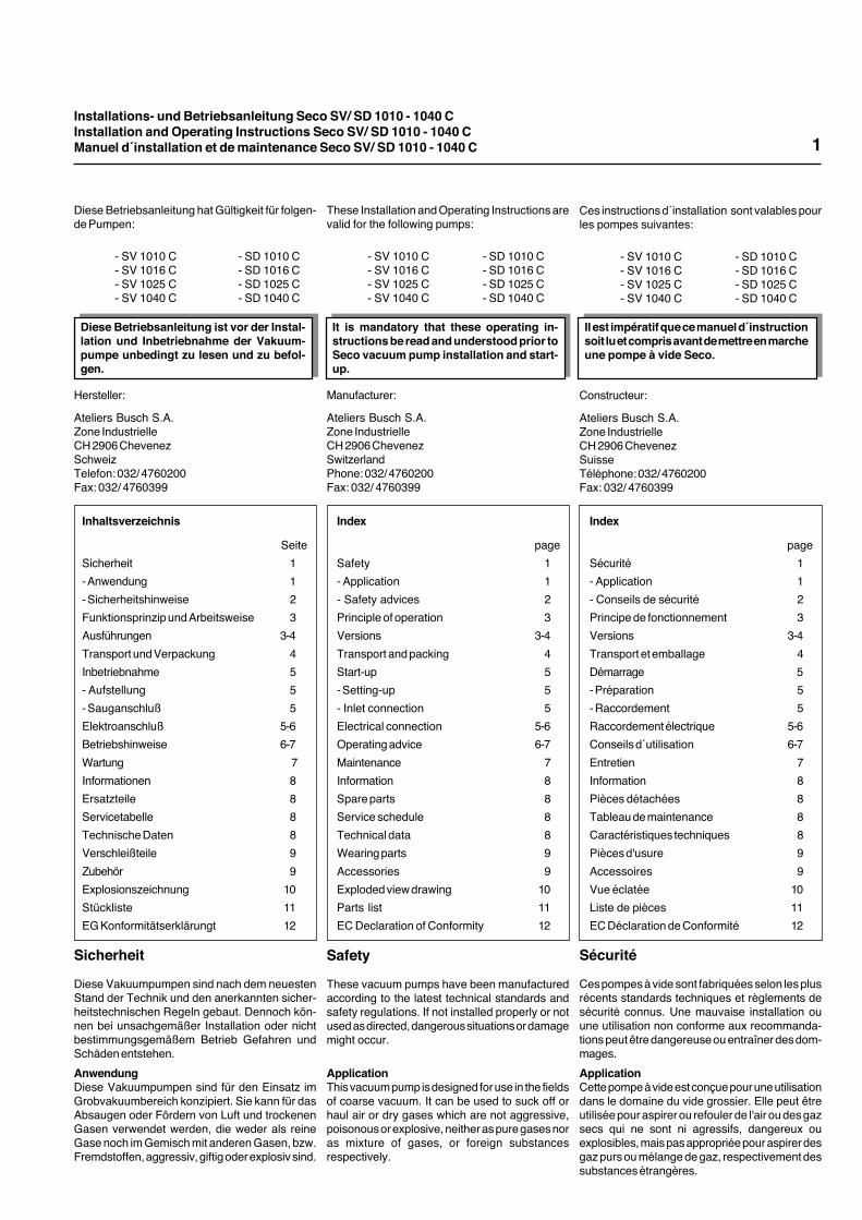
1 Gaseintritt2 Gasaustritt3 Schalldämpferventil
(nur bei SV)Druckregulierventil(nur bei SD)
1 Gas inlet2 Gas discharge3 Discharge silencer valve
(SV series only)Pressure relief valve(SD series only)
1 Orifice d´aspiration2 Echappement3 Soupape de silencieux
(uniquement sur SV)Soupape de réglage de pression(uniquement sur SD)
2
Andere Medien dürfen nicht gefördert werden.Wenden Sie sich im Zweifelsfall an Ihre örtlicheBusch-Vertretung.
SicherheitshinweiseIn dieser Betriebsanleitung werden jeweils vor denbetreffenden Handlungsschritten Sicher-heitshinweise genannt. Diese Hinweise sindunbedingt zu beachten.
Other agents should not be transported. In case ofdoubt, please contact your local Busch-Agency.
Safety adviceIn these operating instructions safety measuresare advised before each step. It is imperative thatthese safety precautions are observed.
Flüssigkeiten und Feststoffe dürfen nicht indie Pumpe gelangen.Im Zweifelsfall unbedingt Rücksprache mitIhrer örtlichen Busch-Vertretung halten.
Liquid and solid particles must not enterthe pump.In case of doubt consult your local BuschAgency.
Des liquides et des particules solides nedoivent pas entrer dans la pompe.En cas de doute, veuillez consulter votreAgence Busch locale.
Certains produits ne doivent pas être aspirés parles pompes; en cas de doute, consulter votreAgence Busch locale.
Conseils de sécuritéDans ce manuel d'installation, différentes indica-tions de sécurité sont mentionnées. Il est impéra-tif que ces indications soient suivies.
SV 1040 C
Installations- und Betriebsanleitung Seco SV/ SD 1010 - 1040 CInstallation and Operating Instructions Seco SV/ SD 1010 - 1040 CManuel d´installation et de maintenance Seco SV/ SD 1010 - 1040 C
Principe de fonctionnement
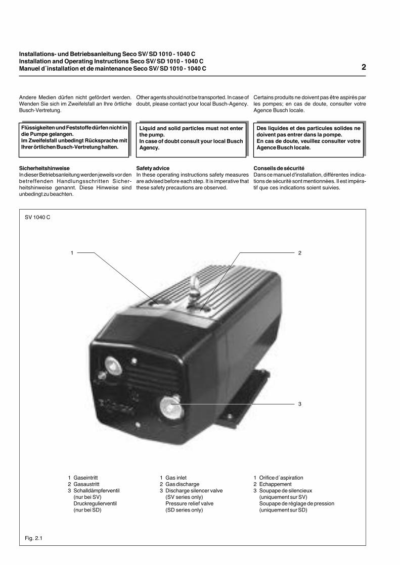
Ces pompes fonctionnent selon le principe despompes à palettes rotatives. Un rotor (4) excen-tré tourne dans un cylindre. La force centrifugepousse les palettes (3), qui coulissent librementdans leur logement, contre la paroi du cylindre.Les palettes divisent l´espace libre en forme decroissant en plusieurs chambres. Lorsqu´unechambre passe devant l´aspiration, le gaz estaspiré puis comprimé lors de la rotation et enfinrejeté à l´échappement.La compression s´effectue sans l´usage de lubri-fiant quel qu´il soit. Le gaz aspiré passe autravers du filtre fin d´aspiration intégré (1). Laversion (SD) est munie d´un filtre supplémentaireintégré (5), situé après la chambre de compres-sion.Un ventilateur efficace se charge de la dissipa-tion de la chaleur au travers du moteur et de lapompe.
Principle of operation
These pumps work according to the rotary vaneprinciple. An eccentrically installed rotor (4) ro-tates in the cylinder. The centrifugal force of therotation pushes the vanes (3), which are glidingin slots in the rotor, towards the wall of the cylin-der. The vanes separate the sickle-shaped spacebetween rotor and cylinder in chambers. Whenthe chambers are connected with the inlet chan-nel, gas is sucked in, compressed by the nextrotation and then discharged.The compression is made without the use offoreign medias for lubrication. The gas is cleanedin the integrated fine-mesh filter (1). There is anadditional filter (5) in the pressure version (SD)which is added subsequently to the compressionchamber.An efficient fan ensures removal of heat from themotor and the pump cover.
Funktionsprinzip und Arbeitsweise
Die Pumpen arbeiten nach dem Drehschieber-prinzip. Ein exzentrisch gelagerter Rotor (4) drehtsich im Zylinder. Durch die Zentrifugalkraft derDrehbewegung werden die Schieber (3), die inSchlitzen im Rotor gleiten, an die Zylinderwandgedrückt. Die Schieber teilen den sichelförmigenRaum zwischen Zylinder und Rotor in Kammernein. Bei Verbindung der Kammern mit dem Saug-kanal wird das Gas angesaugt, bei weiterer Dre-hung verdichtet und anschließend ausgestoßen.Die Verdichtung erfolgt ohne Einsatz von Fremd-medien zur Schmierung. Die angesaugte Gaswird im integrierten Feinfilter (1) gereinigt. Bei derDruckversion (SD) ist ein zusätzlicher Filter (5)dem Verdichtungsraum nachgeschaltet.
Ein leistungsstarker Lüfter sorgt für gute Wärme-abfuhr an Motor und Pumpenkörper.
1 Ansaugfilter2 Filterdeckel3 Schieber4 Rotor5 Druckfilter (nur bei SD)6 Schalldämpferventil (nur bei SV)
1 Inlet filter2 Filter cover3 Vane4 Rotor5 Pressure filter (SD series only)6 Discharge silencer valve(SV series only)
1 Filtre d´aspiration2 Couvercle de filtre3 Palette4 Rotor5 Filtre de refoulement (uniquement sur SD)6 Soupape de silencieux (uniquement sur SV)
Fig. 3.1
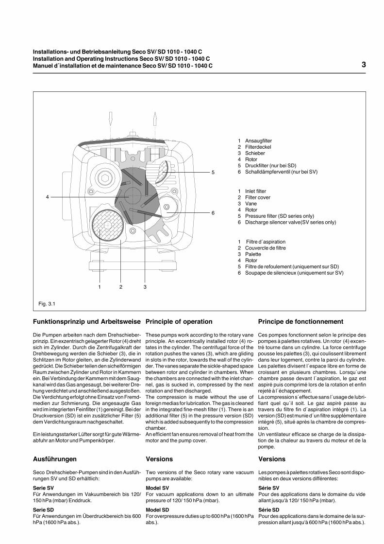
Versions
Two versions of the Seco rotary vane vacuumpumps are available:
Model SVFor vacuum applications down to an ultimatepressure of 120/ 150 hPa (mbar).
Model SDFor overpressure duties up to 600 hPa (1600 hPaabs.).
Ausführungen
Seco Drehschieber-Pumpen sind in den Ausfüh-rungen SV und SD erhältlich:
Serie SVFür Anwendungen im Vakuumbereich bis 120/150 hPa (mbar) Enddruck.
Serie SDFür Anwendungen im Überdruckbereich bis 600hPa (1600 hPa abs.).
Versions
Les pompes à palettes rotatives Seco sont dispo-nibles en deux versions différentes:
Série SVPour des applications dans le domaine du videallant jusqu'à 120/ 150 hPa (mbar).
Série SDPour des applications dans le domaine de la sur-pression allant jusqu'à 600 hPa (1600 hPa abs.).
3
1 2 3
4
5
6
Installations- und Betriebsanleitung Seco SV/ SD 1010 - 1040 CInstallation and Operating Instructions Seco SV/ SD 1010 - 1040 CManuel d´installation et de maintenance Seco SV/ SD 1010 - 1040 C 4
Les indications suivantes définissent le débit depompage et la génération de la pompe:Exemple:
SV 1010 CSV = Vide limite 120/ 150 hPa (mbar)1010 = Débit nominal 10 m3/h (50 Hz)C = Génération
Les deux modèles sont refroidis par air.
Options principales/ accessoires
• Filtre à air à monter en série avec le filtre finintégré en cas d'absorption importante depoussières.
• Soupape de réglage du vide, pour régler unepression d'aspiration (version SV uniquement).
• Soupape de réglage de la pression de refoule-ment (version SD uniquement).
• Clapet anti-retour, monté dans la conduite d'as-piration ou de refoulement, évite une aérationou une désaération accidentelle d'un récipient.
Pour tout renseignement complémentaire concer-nant l’application ou la version, contacter votreAgence Busch locale.
Further pump descriptions state the nominaldisplacement and the design level:Example:
SV 1010 CSV = Ultimate pressure 120/ 150 hPa (mbar)1010 = Nominal flow 10 m3/h (50 Hz)C = Design standard
Both models are air-cooled.
Principal options/ accessories
• Air filter to be coupled to the integral inlet filterwhen high dust loads are being pumped.
• Vacuum relief valve to control inlet pressurewhen pump is used on vacuum duties (only ver-sion SV).
• Pressure relief valve to control pressure whenpump is used on compressor duties (only ver-sion SD).
• Non-return valve protects system againstingress of air or depressurization, should pumpstop for any reason.
In case of questions about the application andversions, please contact your local Busch Agency.
Die weitere Pumpenbezeichnung gibt das Nenn-saugvermögen und den Konstruktionsstand an:Beispiel:
SV 1010 CSV = Enddruck 120/ 150 hPa (mbar)1010 = Nennsaugvermögen 10 m3/h (50 Hz)C = Konstruktionsstand
Beide Ausführungen sind luftgekühlt.
Hauptoptionen/ Zubehör
• Luftfilter zum Vorschalten an den integriertenFeinfilter bei hohem Staubanfall.
• Vakuumregulierventil zum Einstellen eines be-stimmten Ansaugdruckes bei Saugbetrieb (nurAusführung SV).
• Druckregulierventil zum Einstellen eines be-stimmten Ansaugdruckes bei Druckbetrieb (nurAusführung SD).
• Rückschlagventil zum Einbau in die Saug- oderDruckleitung, um eine irrtümlich Be- oderEntlüftung des Rezipienten zu verhindern.
Bei Fragen zur Anwendungen und Ausführung,wenden Sie sich bitte an Ihre örtliche Busch-Vertretung.
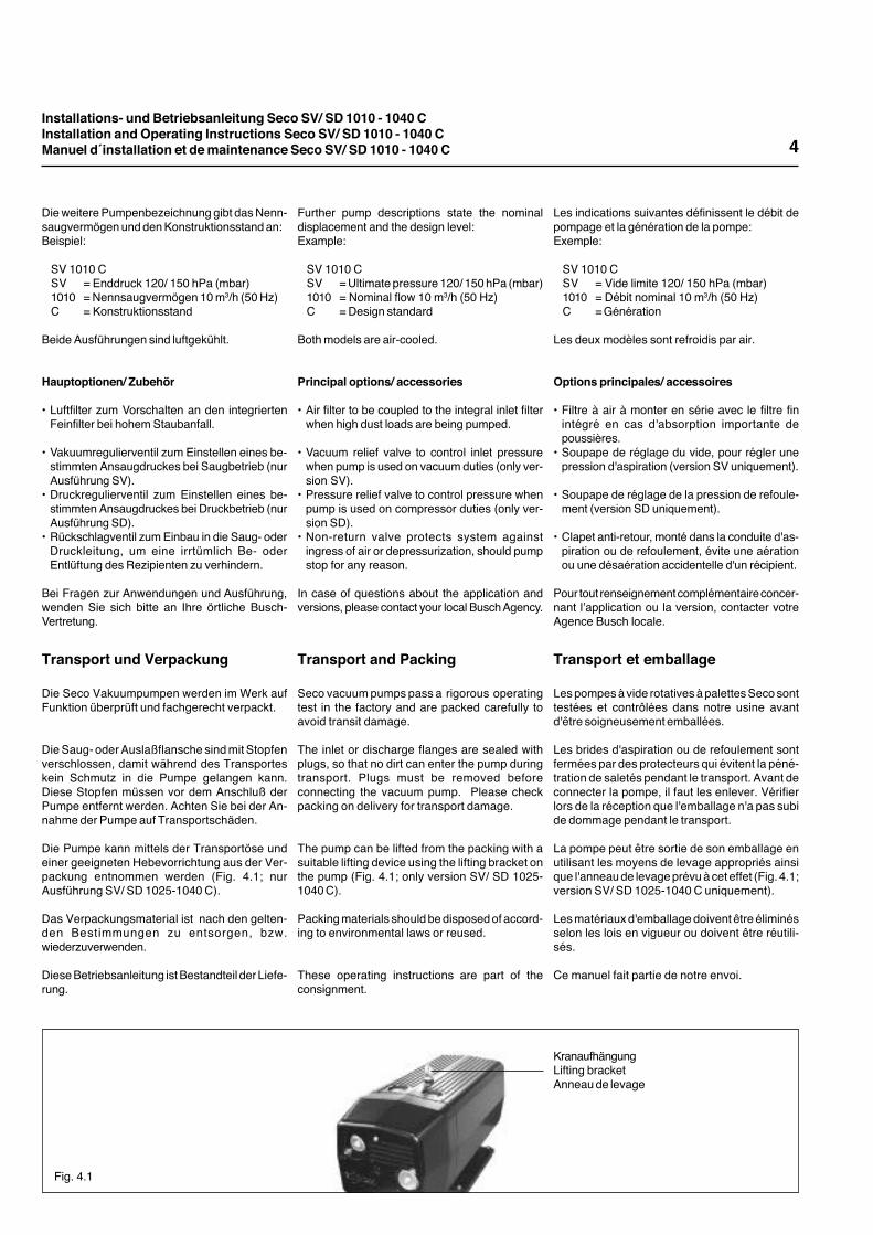
KranaufhängungLifting bracketAnneau de levage
Fig. 4.1
Transport and Packing
Seco vacuum pumps pass a rigorous operatingtest in the factory and are packed carefully toavoid transit damage.
The inlet or discharge flanges are sealed withplugs, so that no dirt can enter the pump duringtransport. Plugs must be removed beforeconnecting the vacuum pump. Please checkpacking on delivery for transport damage.
The pump can be lifted from the packing with asuitable lifting device using the lifting bracket onthe pump (Fig. 4.1; only version SV/ SD 1025-1040 C).
Packing materials should be disposed of accord-ing to environmental laws or reused.
These operating instructions are part of theconsignment.
Transport et emballage
Les pompes à vide rotatives à palettes Seco sonttestées et contrôlées dans notre usine avantd'être soigneusement emballées.
Les brides d'aspiration ou de refoulement sontfermées par des protecteurs qui évitent la péné-tration de saletés pendant le transport. Avant deconnecter la pompe, il faut les enlever. Vérifierlors de la réception que l'emballage n'a pas subide dommage pendant le transport.
La pompe peut être sortie de son emballage enutilisant les moyens de levage appropriés ainsique l'anneau de levage prévu à cet effet (Fig. 4.1;version SV/ SD 1025-1040 C uniquement).
Les matériaux d'emballage doivent être éliminésselon les lois en vigueur ou doivent être réutili-sés.
Ce manuel fait partie de notre envoi.
Transport und Verpackung
Die Seco Vakuumpumpen werden im Werk aufFunktion überprüft und fachgerecht verpackt.
Die Saug- oder Auslaßflansche sind mit Stopfenverschlossen, damit während des Transporteskein Schmutz in die Pumpe gelangen kann.Diese Stopfen müssen vor dem Anschluß derPumpe entfernt werden. Achten Sie bei der An-nahme der Pumpe auf Transportschäden.
Die Pumpe kann mittels der Transportöse undeiner geeigneten Hebevorrichtung aus der Ver-packung entnommen werden (Fig. 4.1; nurAusführung SV/ SD 1025-1040 C).
Das Verpackungsmaterial ist nach den gelten-den Bestimmungen zu entsorgen, bzw.wiederzuverwenden.
Diese Betriebsanleitung ist Bestandteil der Liefe-rung.
Installations- und Betriebsanleitung Seco SV/ SD 1010 - 1040 CInstallation and Operating Instructions Seco SV/ SD 1010 - 1040 CManuel d´installation et de maintenance Seco SV/ SD 1010 - 1040 C
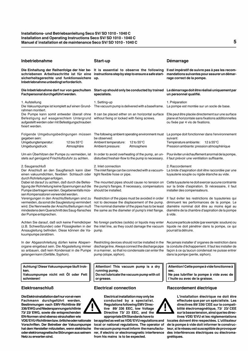
Attention! This vacuum pump is a dryrunning pump.Do not lubricate the vacuum pump with oilor grease.
Attention! Cette pompe à vide fonctionne àsec.Ne pas lubrifier la pompe à vide avec del´huile ou avec de la graisse.
Achtung! Diese Vakuumpumpe läuft trok-ken.Vakuumpumpe nicht mit Öl oder Fettschmieren!
5
Start-up
It is essential to observe the followinginstructions step by step to ensure a safe start-up.
Start-up should only be conducted by trainedspecialists.
1. Setting-upThe vacuum pump is delivered with a baseframe.
It can be placed either on an horizontal surfacewithout fixing or locked with fixing screws.
The following ambient operating environment mustbe observed:Ambient temperature: 12 to 55°CAmbient pressure: Atmosphere
In order to avoid overheating of the pump, an un-disturbed freshair-flow to the pump is necessary.
2. Inlet connectionThe inlet flange can be connected with a vacuum-tight flexible hose or pipe.
The mounted pipes should cause no tension onthe pump's flanges. If necessary, compensatorsshould be installed.
Restriction of the pipes must be avoided in ordernot to decrease the displacement of the pump.The nominal diameter of the pipes has to be leastthe same as the diameter of pump's inlet flange.
No foreign particles (solids) or liquids may enterthe inlet line, as they could damage the vacuumpump.
Restricting devices should not be installed in thedischarge line. Always connect the discharge pipein a manner, so that no condensate can enter thepump (slope, siphon).
Démarrage
Il est impératif de suivre pas à pas les recom-mandations suivantes pour assurer un démar-rage correct de la pompe.
Le démarrage doit être réalisé uniquement parun personnel qualifié.
1. PréparationLa pompe est montée sur un socle de base.
Elle peut être placée directement sur une surfaceplane et horizontale sans fixations additionnellesou fixée par 4 vis de fixations.
La pompe doit fonctionner dans l'environnementsuivant:Température ambiante: 12 à 55°CPression ambiante: pression atmosphérique
Pour éviter un échauffement anormal de la pompe,il faut prévoir une ventilation suffisante.
2. RaccordementLa bride d'aspiration doit être raccordée par unetuyauterie souple ou rigide étanche au vide.
Cette tuyauterie ne doit exercer aucune contraintesur la bride d'aspiration. Si nécessaire, il fautinstaller des compensateurs.
Il faut éviter les restrictions de tuyauteries quidiminuent les performances de la pompe. Lediamètre nominal doit être au moins égal audiamètre de la chambre d'aspiration de la pompeà vide.
Aucune particule solide (par exemple: soudure) ouliquide ne doit pénétrer dans la pompe, ce quipourrait la détruire.
Ne jamais installer d' organes de restriction dansla conduite d'échappement. Il faut les installer defaçon à ce qu'aucun condensat ne puisse entrerdans la pompe (pente, siphon).
Inbetriebnahme
Die Einhaltung der Reihenfolge der hier be-schriebenen Arbeitsschritte ist für einesicherheitsgerechte und funktionssichereInbetriebnahme unbedingt erforderlich.
Die Inbetriebnahme darf nur von geschultemFachpersonal durchgeführt werden.
1. AufstellungDie Vakuumpumpe ist komplett auf einen Grund-rahmen montiert.Die Pumpe kann somit entweder überall ohneBefestigung auf waagerechtem Untergrundaufgestellt werden oder mit Befestigungschraubenfixiert werden.
Folgende Umgebungsbedingungen müssengegeben sein:Umgebungtemperatur: 12 bis 55°CUmgebungsdruck: Atmosphäre
Um ein Überhitzen der Pumpe zu vermeiden, iststets auf genügend Frischluftzufuhr zu achten.
2. SauganschlußDer Anschluß an den Saugflansch kann übereinen vakuumdichten, flexiblen Schlauch oderdurch Rohrleitungen erfolgen.Dabei ist darauf zu achten, daß durch die Befes-tigung der Rohrleitung keine Spannungen auf diePumpe übertragen werden. Gegebenenfalls müs-sen Kompensatoren verwendet werden.Verengungen in den Anschlußleitungen sind zuvermeiden, da sonst die Saugleistung vermindertwird. Die Nennweite der Anschlußleitungen mußmindestens dem Querschnitt des Saug-flanschesder Pumpe entsprechen.
Achten Sie darauf, daß sich keine Fremdkörper(z.B. Schweißzunder) oder Flüssigkeiten in derAnsaugleitung befinden. Diese können die Va-kuumpumpe zerstören.
In der Abgasrohrleitung dürfen keine Absperr-organe eingebaut sein. Die Abgasleitung immerso anbauen, daß kein Kondensat in die Pumpegelangen kann (Gefälle, Syphon).
Raccordement électrique
L'installation électrique ne doit êtreeffectuée que par un spécialiste. Lesdirectives 89/ 336/ CEE sur la compati-bilité électromagnétique, 73/ 23/ CEEsur la basse tension, ainsi que les direc-tives VDE/ EVU et les réglementations
locales doivent être respectées. L'utilisateurde la pompe à vide doit informer le construc-teur, si le réseau est susceptible de provoquerdes interférences électriques ou électroma-gnétiques.
Electrical connection
Electrical installation may only beconducted by a specialist.Regulations following EMV Direc-tive 89/ 336 EEC, low VoltageDirective 73/ 23 EEC, and theappropriate EN Standards have to
be applied as well as VDE/ EVU regulations andlocal or national regulations. The operator ofthe vacuum pump must inform the manufactu-rer, if electric or electromagnetic interferencefrom his mains is to be expected.
Elektroanschluß
Die Elektroinstallation darf nur von ei-nemFachmann durchgeführt werden.Bestimmungen nach EMV-Richtlinie 89/336/ EWG und Niederspannungsrichtlinie73/ 23/ EWG, sowie die entsprechendenEN-Normen sind ebenso einzuhalten wieVDE/ EVU-Richtlinien bzw. örtliche oder nationaleVorschriften. Der Betreiber der Vakuumpumpehat dem Hersteller mitzuteilen, wenn elektrischeoder elektromagnetische Störungen aus seinemNetz zu erwarten sind.
Installations- und Betriebsanleitung Seco SV/ SD 1010 - 1040 CInstallation and Operating Instructions Seco SV/ SD 1010 - 1040 CManuel d´installation et de maintenance Seco SV/ SD 1010 - 1040 C
Conseils d´utilisation
1. Ces pompes à vide peuvent être utilisées pouraspirer de l'air ou des gaz secs qui ne sont niagressifs, dangereux ou explosibles, mais pasappropriée pour aspirer des gaz purs ou mélangede gaz, respectivement des substances étrangè-res.Certains produits ne doivent pas être aspirés parles pompes; en cas de doute, consulter votreAgence Busch locale.
2. Les pompes Seco fonctionnent sans aucunelubrification. Les palettes sont réalisées dans unmatériau à base de carbone spécial qui ne néces-site aucune lubrification.
Attention: N´utiliser aucun lubrifiant (huile ougraisse) sous aucun prétexte.
Operation advice
1. These vacuum pumps can be used to suck offair or dry gases which are not aggressive,poisonous or explosive, neither as pure gases noras mixture of gases, or foreign substancesrespectively.
Other agents should not be transported. In case ofdoubt, please contact your local Busch-Agency.
2. Seco rotary vane pumps work absolutly oil free.The vanes are made of special carbon and do notneed any lubrication.
Caution: Do not lubricate with oil or greaseunder any circumstances.
Betriebshinweise
1. Diese Vakuumpumpe ist für das Absaugen vonLuft und trockenen Gasen verwendet werden, dieweder als reine Gase noch im Gemisch mit anderenGasen, bzw. Fremdstoffen, aggressiv, giftig oderexplosiv sind.
Andere Medien dürfen nicht gefördert werden.Wenden Sie sich im Zweifelsfall an Ihre örtlicheBusch-Vertretung.
2. Seco Drehschieber-Pumpen arbeiten absolutölfrei. Die Schieber sind aus Spezialkohle undbrauchen nicht geschmiert zu werden.
Pumpe unter keinen Umständen mit Öl oderFett schmieren!
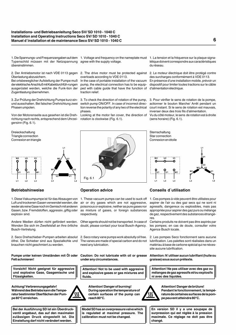
Fig. 6.1
DreieckschaltungTriangle connectionConnexion en triangle
SternschaltungStar connectionConnexion en étoile
6
1. La tension et la fréquence sur la plaque signa-létique doivent correspondre aux caractéristiquesdu réseau.
2. Le moteur électrique doit être protégé contredes surcharges conformément à VDE 0113.En présence d'une installation mobile, prévoir undispositif pour limiter toutes tractions sur le câbled'alimentation électrique.
3. Pour vérifier le sens de rotation de la pompe,actionner le bouton Marche/ Arrêt pendant uncourt instant. Si le sens de rotation est mauvais,inverser deux des trois fils d'alimentation.Vu du côté moteur, le sens de rotation est à droite(sens horaire) (Fig. 6.1).
1. Voltage and frequency on the nameplate mustagree with the supply voltage.
2. The drive motor must be protected againstoverloads according to VDE 0113.In the case of portable installation of the vacuumpump, the electrical connection has to be equip-ped with cable guide that have the function oftraction relief.
3. To check the direction of rotation of the pump,switch pump ON/OFF. In case of incorrect direc-tion reverse the polarity of any two of the electricalphases.Looking at the motor fan cover, the direction ofrotation is clockwise (Fig. 6.1).
1. Die Spannungs- und Frequenzangaben auf demTypenschild müssen mit der Netzspannungübereinstimmen.
2. Der Antriebsmotor ist nach VDE 0113 gegenÜberlastung abzusichern.Bei ortsbeweglicher Aufstellung der Pumpe mußder elektrische Anschluß mit Kabeldurchfüh-rungenausgerüstet werden, welche die Funk-tion derZugentlastung übernehmen.
3. Zur Prüfung der Drehrichtung Pumpe kurz ein-und ausschalten. Bei falscher Drehrichtung zweiPhasen umpolen.
Von der Motorenseite aus gesehen ist die Dreh-richtung nach rechts, entsprechend dem Uhrzei-gersinn (Fig. 6.1).
!"
!# !$
%$ &$'$
'"
%" &"
%$ &$'$
'" %"&"
!" !#!$
%$ &$'$
'" %"&"
!" !#!$
!"
!# !$
%$
&$
'$
'"
%"
&"
Attention! Ne pas utiliser avec des gaz oumélanges de gaz agressifs et/ou explosifsni avec des liquides.
Attention! Not to be used with aggresiveand explosive gases or gas mixtures andfluids.
Vorsicht! Nicht geeignet für aggressiveund explosive Gase, Gasgemische undFlüssigkeiten.
Attention! Danger de brûlure!Pendant le fonctionnement, la tempé-rature de certaines surfaces de la pom-pe peuvent atteindre 80°C.
Attention! Danger of burning!During operation the temperature ofcertain surfaces of the pump canreach 80°C.
Achtung! Verbrennungsgefahr!Während des Betriebs kann die Tempe-ratur bestimmter Oberflächen der Pum-pe 80°C erreichen.
Bei der Ausführung SD ist ein Überdruck-ventil angebaut, das auf den maximalenzulässigen Druck eingestellt ist. DieEinstellung darf nicht verändert werden.
Model SD has an overpressure valve whichis regulated at maximal pressure. Thecalibration must not be changed.
En version SD il y a une soupape desurpression qui est réglée à la pressionmaximale. Ce réglage ne doit pas êtrechangé.
Installations- und Betriebsanleitung Seco SV/ SD 1010 - 1040 CInstallation and Operating Instructions Seco SV/ SD 1010 - 1040 CManuel d´installation et de maintenance Seco SV/ SD 1010 - 1040 C
Wartung
Zu allen Wartungsarbeiten muß die Vakuum-pumpe ausgeschaltet werden und gegen ver-sehentliches Anschalten gesichert sein.
1. Der Ansaugfilter (Fig. 3.1.1) und der Druckfilter(Fig. 3.1.5) sind je nach Staubanfall der ange-saugten Luft regelmäßig zu reinigen. Filterpatronenvon innen nach außen mit Druckluft durchblasen.Bei stärkerer Verschmutzung muß der Filterausgewechselt werden. Die Filter können durchLösen des Filterdeckels (Fig. 3.1.2) entnommenwerden.
2. Die Schieber haben je nach Belastung undBetriebsart der Vakuumpumpe eine Lebensdauervon 6000 bis 10000 Betriebsstunden.Neue Schieber müssen eingesetzt werden, wenndie Schieberhöhe nur noch 75 % der Schlitztiefeim Rotor beträgt. Pro Millimeter über der Mindest-breite kann mit weiteren 1000 Stunden Standzeitder Schieber gerechnet werden.
3. Schieberwechsel erfolgt durch die Demontagedes Filterdeckels (Fig. 3.1.2) und des Zylinder-deckels (Fig. 3.1.7). Verdichtungsraum mit trocke-ner Druckluft ausblasen.
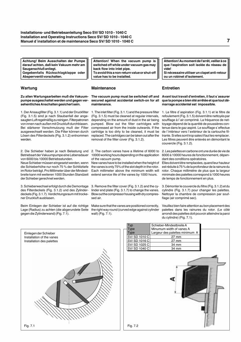
Beim Einlegen der Schieber ist auf die richtigeLage (Radius) zu achten (die abgerundete Seitegegen die Zylinderwand) (Fig. 7.1).
Maintenance
The vacuum pump must be switched off andsecured against accidental switch-on for allmaintenance.
1. The inlet filter (Fig. 3.1.1) and the pressure filter(Fig. 3.1.5) must be cleaned at regular intervals,depending on the amount of dust in the air beingpumped. Blow out the filter cartridges withcompressed air from the inside outwards. If thecartridge is too dirty to be cleaned, it must bereplaced. The cartridges can be taken out after theremoval of the filter cover (Fig. 3.1.2).
2. The carbon vanes have a lifetime of 6000 to10000 working hours depending on the applicationof the vacuum pump.New vanes have to be installed when the height ofthe vanes is only 75% of the slot depth in the rotor.Each millimeter above the minimum width willextend service life of the vanes by 1000 hours.
3. Remove the filter cover (Fig. 3.1.2) and the cy-linder end plate (Fig. 3.1.7) to change the vanes.Blow out the compressor housing with dry compres-sed air.
Make sure that the vanes are positioned correctly,the right way round (curved edge against cylinderwall) (Fig. 7.1).
Entretien
Avant tout travail d'entretien, il faut s´assurerque la pompe a bien été arrêtée et que tout dé-marrage accidentel est impossible.
1. Le filtre d´aspiration (Fig. 3.1.1) et le filtre derefoulement (Fig. 3.1.5) doivent être nettoyés parsoufflage à l´air comprimé. La fréquence de net-toyage dépend de la quantité de poussières con-tenue dans le gaz aspiré. Le soufflage s´effectuede l´intérieur vers l´extérieur de la cartouche fil-trante. Si elles sont trop sales il faut les remplacer.Les filtres peuvent être enlevés en démontant lecouvercle (Fig. 3.1.2).
2. Les palettes en carbone ont une durée de vie de6000 à 10000 heures de fonctionnement, dépen-dant des conditions opératoires.Elles doivent être remplacées, quand leur hauteurest réduite à 75 % de la profondeur de la rainure durotor. Chaque millimètre de plus que la largeurminimale des palettes correspond à 1000 heuresde temps de fonctionnement en plus.
3. Démonter le couvercle du filtre (Fig. 3.1.2) et ducylindre (Fig. 3.1.7) pour changer les palettes.Nettoyer la chambre de compression par souf-flage (air comprimé sec).
Veuillez bien faire attention au bon placement despalettes dans les rainures du rotor. (Le côtéarrondi des palettes doit pouvoir atteindre la paroidu cylindre) (Fig. 7.1).
Einlegen der SchieberInstallation of the vanesInstallation des palettes
Fig. 7.1 Fig. 7.2
TypTypeType
Schieber-Mindestbreite AMinumum width of vanes ALargeur des palettes minimum A
SV/ SD 1010 CSV/ SD 1016 CSV/ SD 1025 CSV/ SD 1040 C
27 mm 27 mm 34 mm 34 mm
7
Achtung! Beim Ausschalten der Pumpedarauf achten, daß kein Vakuum mehr amSauganschluß anliegt.Gegebenfalls Rückschlagklappe oderAbsperrventil vorschalten.
Attention! When the vacuum pump isswitched off while under vacuum gas mayback flow into inlet pipe.To avoid this a non-return value or shut-offvalue has to be installed.
Attention! Au moment de l'arrêt, veiller à ceque l'aspiration soit isolée du réseau devide!Si nécessaire utiliser un clapet anti-retourou un robinet d'isolement.
Installations- und Betriebsanleitung Seco SV/ SD 1010 - 1040 CInstallation and Operating Instructions Seco SV/ SD 1010 - 1040 CManuel d´installation et de maintenance Seco SV/ SD 1010 - 1040 C 8
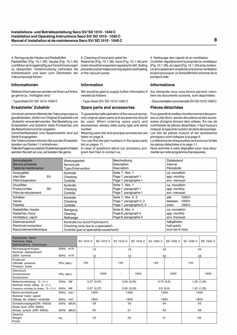
4. Reinigung der Haube und RadiallüfterRadiallüfter (Fig. 10.1.39), Haube (Fig. 10.1.40)und Motor sind regelmäßig auf Verschmutzungenzu überprüfen. Verschmutzung verhindert dieKühlluftzufuhr und kann zum Überhitzen derVakuumpumpe führen.
4. Cleaning of hood and radial fanRadial fan (Fig. 10.1.39), hood (Fig. 10.1.40) andmotor should be inspected regularly for dirt. Soilingprevents cool air intake and may lead to overheatingof the vacuum pump.
4. Nettoyage des capots et du ventilateurContrôler régulièrement la propreté du ventilateur(Fig. 10.1.39), du capot (Fig. 10.1.40) et du moteur.Un encrassement empêche une bonne ventilationet peut provoquer un échauffement anormal de lapompe à vide.
InformationsSur demande nous vous ferons parvenir volon-tiers les documents suivants, sont disponibles:
- Documentation commerciale SV/ SD 1010-1040 C
Pièces détachéesPour garantir le meilleur fonctionnement des pom-pes à vide Seco, seules des pièces et des acces-soires d'origine doivent être utilisés. En cas decommande de pièces détachées, il faut toujoursindiquer le type et le numéro de série de la pompe.Les kits de pièces d'usure et les accessoiresprincipaux sont indiqués à la page 9.La référence de chaque pièce se trouve sur la listede pièces détachées à la page 11.Nous sommes à votre disposition pour vous docu-menter sur notre programme d'accessoires.
InformationWe would be glad to supply further information ifneeded as follows:
- Type sheet SV/ SD 1010-1040 C
Spare parts and accessoriesTo guarantee safe operation of the vacuum pump,only original spare parts and accessories shouldbe used. When ordering spare parts andaccessories, always state pump type and serialnumber.Wearing parts kits and principal accessories arelisted on page 9.You can find the part numbers in the spare partslist on pages 11.In case of questions about our accessory pro-gram feel free to contact us.
InformationenWeitere Informationen senden wir Ihnen auf Anfra-ge gerne zu. Verfügbar sind:
- Typenblatt SV/ SD 1010-1040 C
Ersatzteile/ ZubehörUm einen sicheren Betrieb der Vakuumpumpe zugewährleisten, dürfen nur Original-Ersatzteile und-Zubehör verwendet werden. Bei Bestellung vonErsatzteilen und Zubehör stets Pumpentyp unddie Maschinennummer angeben.Verschleißteilsätze und Hauptzubehör sind aufSeite 9 angegeben.Die Teilenummern können Sie aus den Ersatzteil-tabellen auf Seiten 11 entnehmen.Falls Sie Fragen zu unserem Zubehörprogramm habenwenden Sie sich an uns, wir beraten Sie gerne.
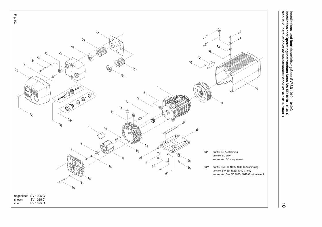
SD 1040 C
-
1600
SD 1025 C
-
1600
SD 1010 C
-
1600
SD 1016 C
-
1600
SV 1016 C
150
-
SV 1025 C
120
-
SV 1040 C
120
-
0,37 (0,37)
0,37 (0,37)1500
1800
22
0,55 (0,55)
0,55 (0,55)1500
1800
26
0,75 (0,9)
0,9 (0,9)1500
1800
31
1,25 (1,25)
1,25 (1,25)1500
1800
38
16
19
59
61
10
12
58
60
25
30
60
62
40
48
65
68
SV 1010 C
150
-
Technische DatenTechnical DataSpécifications TechniquesNennsaugvermögen 50Hz m3/hNominal displacementDébit nominal 60Hz m3/hEnddruckUltimate pressure hPa (abs.)Pression finaleÜberdruckOverpressure hPa (abs.)SurpressionMotornennleistung 3~ (1~) 50Hz kWNominal motor rating 3~ (1~)Puissance nominale du moteur 3~ (1~) 60Hz kWMotornenndrehzahl 50Hz min-1
Nominal motor speedVitesse de rotation nominale 60Hz min-1
Schalldruckpegel(DIN 45635) 50Hz dB(A)Noise level (DIN 45635)Niveau sonore (DIN 45635) 60Hz dB(A)GewichtWeight kgPoids
WartungsarbeitService jobType d'interventionKontrolleCheckingContrôleKontrolleCheckingContrôleKontrolleCheckingContrôleReinigungCleaningNettoyageKontrolle (nur durch Fachmann!)Checking (only due to a specialist!)Contrôle (par un spécialiste seulement!)
ZeitabstandIntervalPériodicitéca. monatlichapp. monthlyenv. mensuelca. monatlichapp. monthlyenv. mensuelalle 1000 hbetween 1000 hentre 1000 hca. monatlichapp. monthlyenv. mensuelhalbjährlichhalf yearlytous les 6 mois
ServicetabelleService scheduleTable de maintenanceAnsaugfilterInlet filter SVFiltre d'aspirationDruckfilterPressure filter SDFiltre de refoulementSchieberVanesPalettesRadiallüfter, HaubeRadial fan, hoodVentilateur, capotElektroanschlußElectrical connectionRaccordement électrique
BeschreibungDescriptionDescriptionSeite 7, Abs. 1Page 7, paragraph 1Page 7, paragraphe 1Seite 7, Abs. 1Page 7, paragraph 1Page 7, paragraphe 1Seite 7, Abs. 2, 3Page 7, paragraph 2, 3Page 7, paragraphe 2, 3Seite 8, Abs. 4Page 8, paragraph 4Page 8, paragraphe 4
Installations- und Betriebsanleitung Seco SV/ SD 1010 - 1040 CInstallation and Operating Instructions Seco SV/ SD 1010 - 1040 CManuel d´installation et de maintenance Seco SV/ SD 1010 - 1040 C
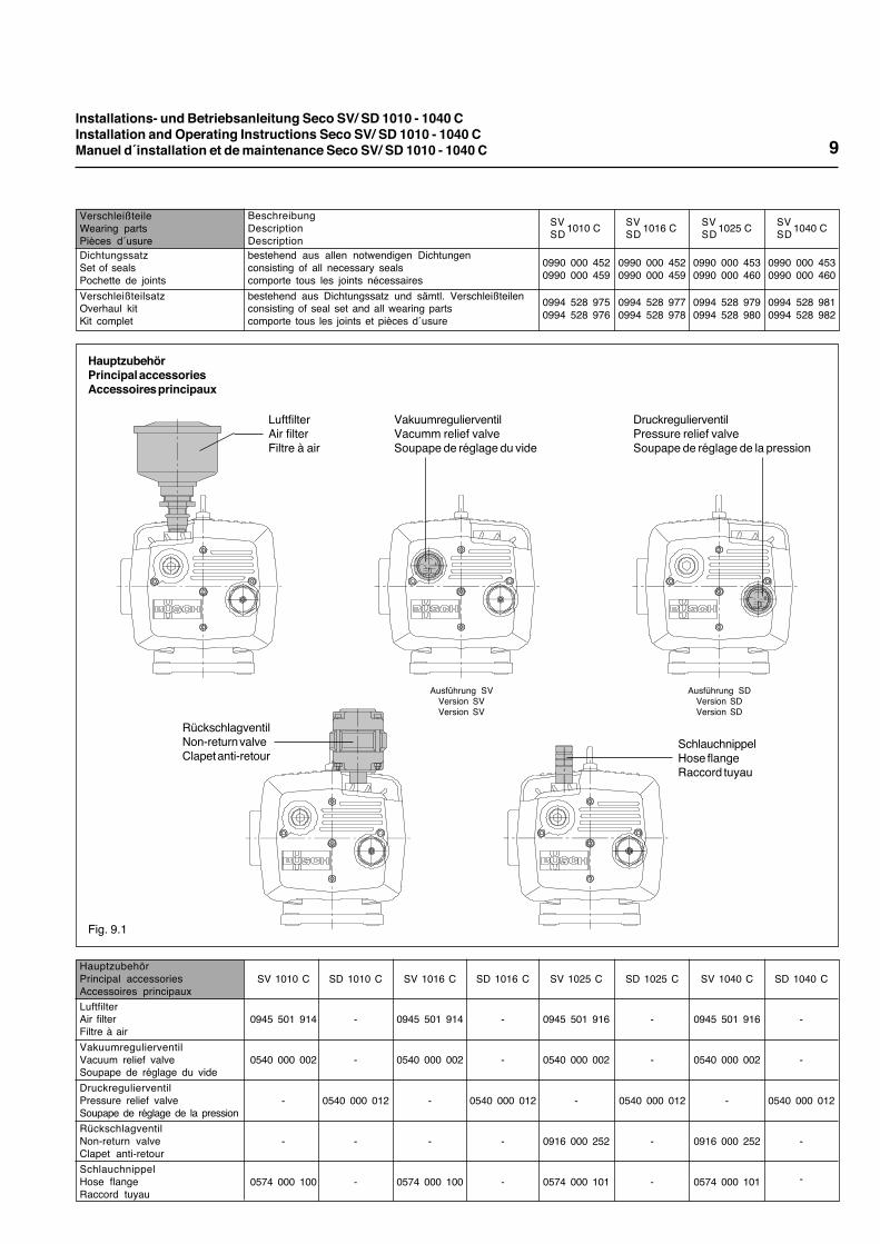
BeschreibungDescriptionDescriptionbestehend aus allen notwendigen Dichtungenconsisting of all necessary sealscomporte tous les joints nécessairesbestehend aus Dichtungssatz und sämtl. Verschleißteilenconsisting of seal set and all wearing partscomporte tous les joints et pièces d´usure
1010 C 1016 C 1025 C 1040 CSVSD
SVSD
SVSD
SVSD
0990 000 4520990 000 459
0994 528 9750994 528 976
0990 000 4520990 000 459
0994 528 9770994 528 978
0990 000 4530990 000 460
0994 528 9790994 528 980
0990 000 4530990 000 460
0994 528 9810994 528 982
VerschleißteileWearing partsPièces d´usureDichtungssatzSet of sealsPochette de jointsVerschleißteilsatzOverhaul kitKit complet
9
SD 1016 C
-
-
0540 000 012
-
-
SV 1010 C
0945 501 914
0540 000 002
-
-
0574 000 100
SD 1010 C
-
-
0540 000 012
-
-
SV 1016 C
0945 501 914
0540 000 002
-
-
0574 000 100
SV 1025 C
0945 501 916
0540 000 002
-
0916 000 252
0574 000 101
SD 1025 C
-
-
0540 000 012
-
-
SV 1040 C
0945 501 916
0540 000 002
-
0916 000 252
0574 000 101
SD 1040 C
-
-
0540 000 012
-
-
HauptzubehörPrincipal accessoriesAccessoires principauxLuftfilterAir filterFiltre à airVakuumregulierventilVacuum relief valveSoupape de réglage du videDruckregulierventilPressure relief valveSoupape de réglage de la pressionRückschlagventilNon-return valveClapet anti-retourSchlauchnippelHose flangeRaccord tuyau
HauptzubehörPrincipal accessoriesAccessoires principaux
Fig. 9.1
LuftfilterAir filterFiltre à air
VakuumregulierventilVacumm relief valveSoupape de réglage du vide
DruckregulierventilPressure relief valveSoupape de réglage de la pression
RückschlagventilNon-return valveClapet anti-retour
SchlauchnippelHose flangeRaccord tuyau
Ausführung SVVersion SVVersion SV
Ausführung SDVersion SDVersion SD
Installations- und Betriebsanleitung Seco SV/ SD
1010 - 1040 CInstallation and O
perating Instructions Seco SV/ SD 1010 - 1040 C
Manuel d´installation et de m
aintenance Seco SV/ SD 1010 - 1040 C
10
Fig. 10.1
!"#$%&#$'($)"*%&+#"!,-.#*/0!$'($0!12*"#$-.#*/0!$'($"!/3".4.!5
667
6677 !"#$%&#$'89$'($:;<=9$:;>;$?$)"*%&+#"!,-.#*/0!$'89$'($:;<=9$:;>;$?$0!12*"#$-.#*/0!$'89$'($:;<=9$:;>;$?$"!/3".4.!5
@;
@<
@:
<A<B
C; <>
<=
<@
<<
<=7
<@7
C<7C<
><77
:B
<;
:A
B
A
D
:;
=
:D
:=
:>
:@
:C
:@7<
D:
:
CB
DC
D<
>D
>C
><
>>
>=77
>;
=B
=A>B=:
=;=>
==
>@
>A
abgebildet SV 1025 Cshown SV 1025 Cvue SV 1025 C
Installations- und Betriebsanleitung Seco SV/ SD 1010 - 1040 CInstallation and Operating Instructions Seco SV/ SD 1010 - 1040 CManuel d´installation et de maintenance Seco SV/ SD 1010 - 1040 C
SV 1010 C
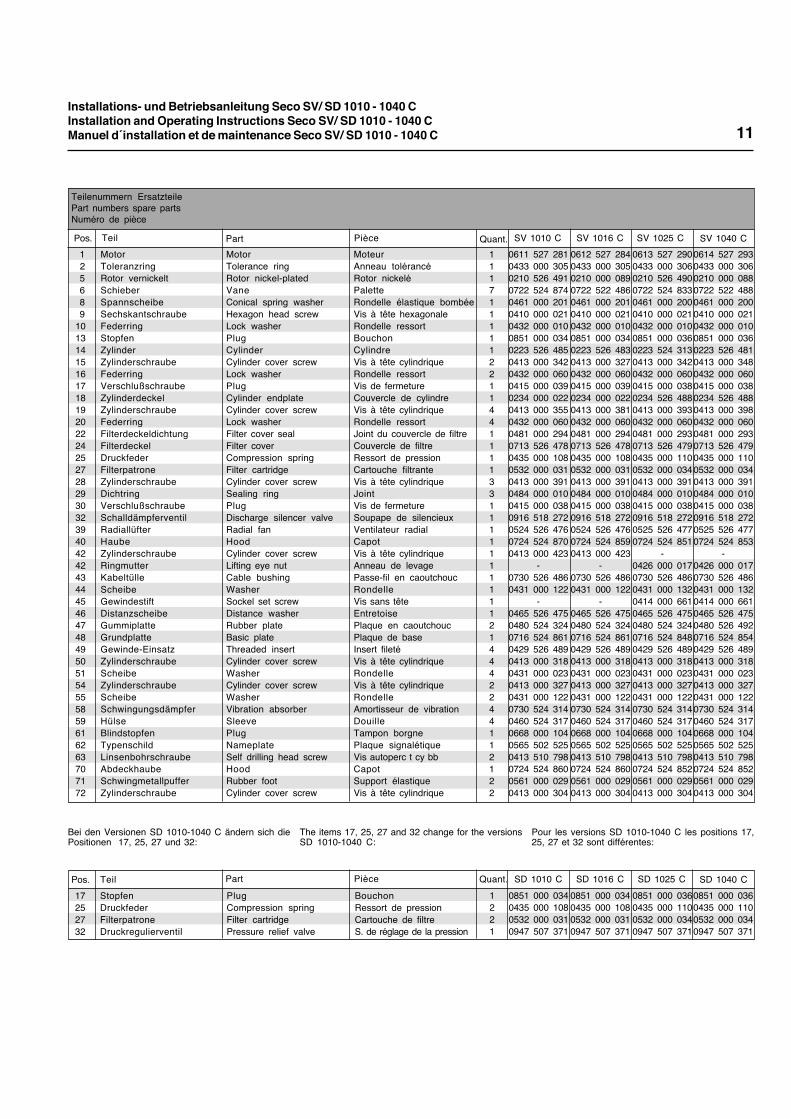
Teilenummern ErsatzteilePart numbers spare partsNuméro de pièce
SV 1040 CSV 1025 CSV 1016 C0614 527 2930433 000 3060210 000 0880722 522 4880461 000 2000410 000 0210432 000 0100851 000 0360223 526 4810413 000 3480432 000 0600415 000 0380234 526 4880413 000 3980432 000 0600481 000 2930713 526 4790435 000 1100532 000 0340413 000 3910484 000 0100415 000 0380916 518 2720525 526 4770724 524 853
-0426 000 0170730 526 4860431 000 1320414 000 6610465 526 4750480 526 4920716 524 8540429 526 4890413 000 3180431 000 0230413 000 3270431 000 1220730 524 3140460 524 3170668 000 1040565 502 5250413 510 7980724 524 8520561 000 0290413 000 304
0612 527 2840433 000 3050210 000 0890722 522 4860461 000 2010410 000 0210432 000 0100851 000 0340223 526 4830413 000 3270432 000 0600415 000 0390234 000 0220413 000 3810432 000 0600481 000 2940713 526 4780435 000 1080532 000 0310413 000 3910484 000 0100415 000 0380916 518 2720524 526 4760724 524 8590413 000 423
-0730 526 4860431 000 122
-0465 526 4750480 524 3240716 524 8610429 526 4890413 000 3180431 000 0230413 000 3270431 000 1220730 524 3140460 524 3170668 000 1040565 502 5250413 510 7980724 524 8600561 000 0290413 000 304
0611 527 2810433 000 3050210 526 4910722 524 8740461 000 2010410 000 0210432 000 0100851 000 0340223 526 4850413 000 3420432 000 0600415 000 0390234 000 0220413 000 3550432 000 0600481 000 2940713 526 4780435 000 1080532 000 0310413 000 3910484 000 0100415 000 0380916 518 2720524 526 4760724 524 8700413 000 423
-0730 526 4860431 000 122
-0465 526 4750480 524 3240716 524 8610429 526 4890413 000 3180431 000 0230413 000 3270431 000 1220730 524 3140460 524 3170668 000 1040565 502 5250413 510 7980724 524 8600561 000 0290413 000 304
Quant.1117111112211441111331111111111214442244112122
MoteurAnneau tolérancéRotor nickeléPaletteRondelle élastique bombéeVis à tête hexagonaleRondelle ressortBouchonCylindreVis à tête cylindriqueRondelle ressortVis de fermetureCouvercle de cylindreVis à tête cylindriqueRondelle ressortJoint du couvercle de filtreCouvercle de filtreRessort de pressionCartouche filtranteVis à tête cylindriqueJointVis de fermetureSoupape de silencieuxVentilateur radialCapotVis à tête cylindriqueAnneau de levagePasse-fil en caoutchoucRondelleVis sans têteEntretoisePlaque en caoutchoucPlaque de baseInsert filetéVis à tête cylindriqueRondelleVis à tête cylindriqueRondelleAmortisseur de vibrationDouilleTampon borgnePlaque signalétiqueVis autoperc t cy bbCapotSupport élastiqueVis à tête cylindrique
PiècePartMotorTolerance ringRotor nickel-platedVaneConical spring washerHexagon head screwLock washerPlugCylinderCylinder cover screwLock washerPlugCylinder endplateCylinder cover screwLock washerFilter cover sealFilter coverCompression springFilter cartridgeCylinder cover screwSealing ringPlugDischarge silencer valveRadial fanHoodCylinder cover screwLifting eye nutCable bushingWasherSockel set screwDistance washerRubber plateBasic plateThreaded insertCylinder cover screwWasherCylinder cover screwWasherVibration absorberSleevePlugNameplateSelf drilling head screwHoodRubber footCylinder cover screw
TeilPos. 1 Motor 2 Toleranzring 5 Rotor vernickelt 6 Schieber 8 Spannscheibe 9 Sechskantschraube 10 Federring 13 Stopfen 14 Zylinder 15 Zylinderschraube 16 Federring 17 Verschlußschraube 18 Zylinderdeckel 19 Zylinderschraube 20 Federring 22 Filterdeckeldichtung 24 Filterdeckel 25 Druckfeder 27 Filterpatrone 28 Zylinderschraube 29 Dichtring 30 Verschlußschraube 32 Schalldämpferventil 39 Radiallüfter 40 Haube 42 Zylinderschraube 42 Ringmutter 43 Kabeltülle 44 Scheibe 45 Gewindestift 46 Distanzscheibe 47 Gummiplatte 48 Grundplatte 49 Gewinde-Einsatz 50 Zylinderschraube 51 Scheibe 54 Zylinderschraube 55 Scheibe 58 Schwingungsdämpfer 59 Hülse 61 Blindstopfen 62 Typenschild 63 Linsenbohrschraube 70 Abdeckhaube 71 Schwingmetallpuffer 72 Zylinderschraube
SD 1040 CSD 1016 CSD 1010 C0851 000 0340435 000 1080532 000 0310947 507 371
0851 000 0340435 000 1080532 000 0310947 507 371
SD 1025 C0851 000 0360435 000 1100532 000 0340947 507 371
0851 000 0360435 000 1100532 000 0340947 507 371
Quant.1221
BouchonRessort de pressionCartouche de filtreS. de réglage de la pression
Pièce
PlugCompression springFilter cartridgePressure relief valve
Part
17 Stopfen 25 Druckfeder 27 Filterpatrone 32 Druckregulierventil
Pos. Teil
0613 527 2900433 000 3060210 526 4900722 524 8330461 000 2000410 000 0210432 000 0100851 000 0360223 524 3130413 000 3420432 000 0600415 000 0380234 526 4880413 000 3930432 000 0600481 000 2930713 526 4790435 000 1100532 000 0340413 000 3910484 000 0100415 000 0380916 518 2720525 526 4770724 524 851
-0426 000 0170730 526 4860431 000 1320414 000 6610465 526 4750480 524 3240716 524 8480429 526 4890413 000 3180431 000 0230413 000 3270431 000 1220730 524 3140460 524 3170668 000 1040565 502 5250413 510 7980724 524 8520561 000 0290413 000 304
Pour les versions SD 1010-1040 C les positions 17,25, 27 et 32 sont différentes:
The items 17, 25, 27 and 32 change for the versionsSD 1010-1040 C:
Bei den Versionen SD 1010-1040 C ändern sich diePositionen 17, 25, 27 und 32:
11
Installations- und Betriebsanleitung Seco SV/ SD 1010 - 1040 CInstallation and Operating Instructions Seco SV/ SD 1010 - 1040 CManuel d´installation et de maintenance Seco SV/ SD 1010 - 1040 C 12
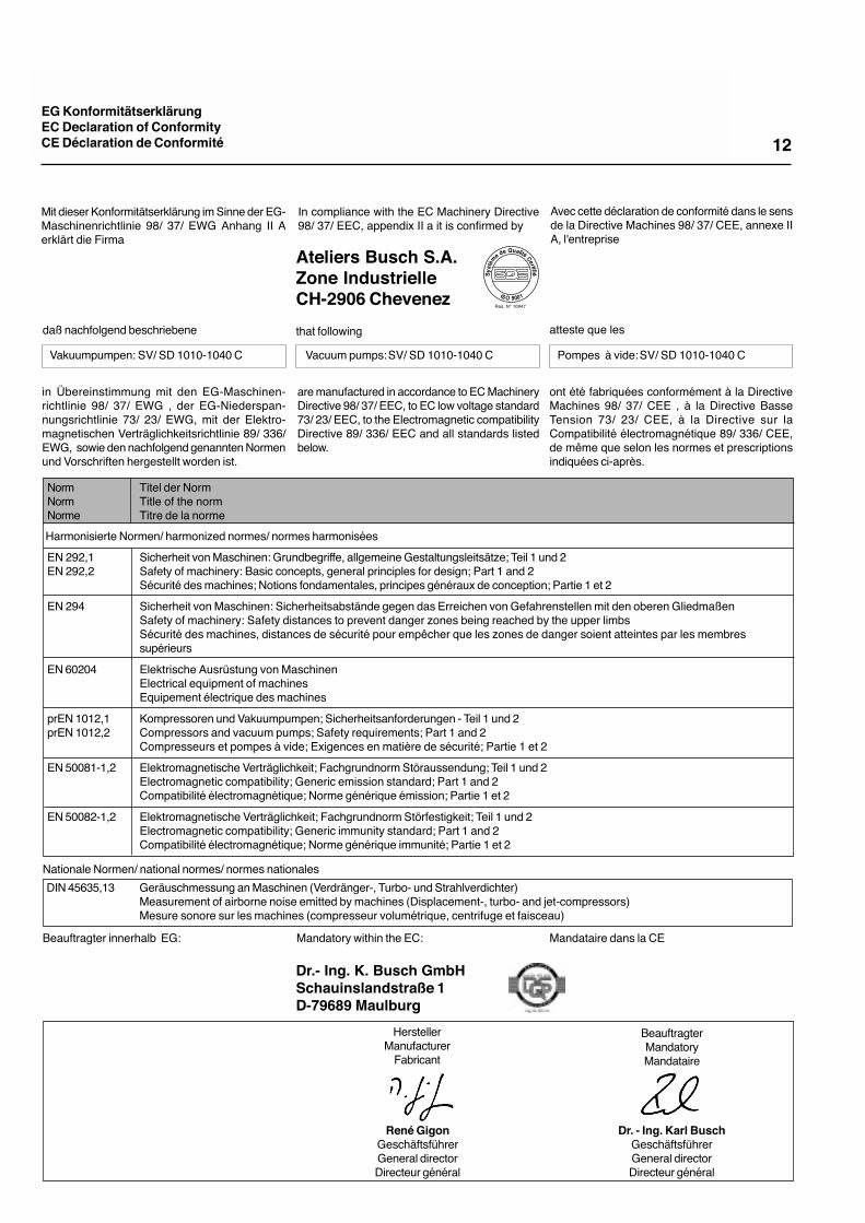
EG KonformitätserklärungEC Declaration of ConformityCE Déclaration de Conformité
Mit dieser Konformitätserklärung im Sinne der EG-Maschinenrichtlinie 98/ 37/ EWG Anhang II Aerklärt die Firma
daß nachfolgend beschriebene
Ateliers Busch S.A.Zone IndustrielleCH-2906 Chevenez
in Übereinstimmung mit den EG-Maschinen-richtlinie 98/ 37/ EWG , der EG-Niederspan-nungsrichtlinie 73/ 23/ EWG, mit der Elektro-magnetischen Verträglichkeitsrichtlinie 89/ 336/EWG, sowie den nachfolgend genannten Normenund Vorschriften hergestellt worden ist.
ont été fabriquées conformément à la DirectiveMachines 98/ 37/ CEE , à la Directive BasseTension 73/ 23/ CEE, à la Directive sur laCompatibilité électromagnétique 89/ 336/ CEE,de même que selon les normes et prescriptionsindiquées ci-après.
Dr.- Ing. K. Busch GmbHSchauinslandstraße 1D-79689 Maulburg
Avec cette déclaration de conformité dans le sensde la Directive Machines 98/ 37/ CEE, annexe IIA, l'entreprise
atteste que les
In compliance with the EC Machinery Directive98/ 37/ EEC, appendix II a it is confirmed by
that following
are manufactured in accordance to EC MachineryDirective 98/ 37/ EEC, to EC low voltage standard73/ 23/ EEC, to the Electromagnetic compatibilityDirective 89/ 336/ EEC and all standards listedbelow.
Dr. - Ing. Karl BuschGeschäftsführerGeneral directorDirecteur général
René GigonGeschäftsführerGeneral directorDirecteur général
BeauftragterMandatoryMandataire
HerstellerManufacturer
Fabricant
Vakuumpumpen: SV/ SD 1010-1040 C
Beauftragter innerhalb EG: Mandatory within the EC: Mandataire dans la CE
Pompes à vide:SV/ SD 1010-1040 CVacuum pumps:SV/ SD 1010-1040 C
Nationale Normen/ national normes/ normes nationales
Harmonisierte Normen/ harmonized normes/ normes harmonisées
NormNormNorme
EN 292,1EN 292,2
EN 294
EN 60204
prEN 1012,1prEN 1012,2
EN 50081-1,2
EN 50082-1,2
Titel der NormTitle of the normTitre de la norme
Sicherheit von Maschinen: Grundbegriffe, allgemeine Gestaltungsleitsätze; Teil 1 und 2Safety of machinery: Basic concepts, general principles for design; Part 1 and 2Sécurité des machines; Notions fondamentales, principes généraux de conception; Partie 1 et 2
Sicherheit von Maschinen: Sicherheitsabstände gegen das Erreichen von Gefahrenstellen mit den oberen GliedmaßenSafety of machinery: Safety distances to prevent danger zones being reached by the upper limbsSécurité des machines, distances de sécurité pour empêcher que les zones de danger soient atteintes par les membressupérieurs
Elektrische Ausrüstung von MaschinenElectrical equipment of machinesEquipement électrique des machines
Kompressoren und Vakuumpumpen; Sicherheitsanforderungen - Teil 1 und 2Compressors and vacuum pumps; Safety requirements; Part 1 and 2Compresseurs et pompes à vide; Exigences en matière de sécurité; Partie 1 et 2
Elektromagnetische Verträglichkeit; Fachgrundnorm Störaussendung; Teil 1 und 2Electromagnetic compatibility; Generic emission standard; Part 1 and 2Compatibilité électromagnétique; Norme générique émission; Partie 1 et 2
Elektromagnetische Verträglichkeit; Fachgrundnorm Störfestigkeit; Teil 1 und 2Electromagnetic compatibility; Generic immunity standard; Part 1 and 2Compatibilité électromagnétique; Norme générique immunité; Partie 1 et 2
Geräuschmessung an Maschinen (Verdränger-, Turbo- und Strahlverdichter)Measurement of airborne noise emitted by machines (Displacement-, turbo- and jet-compressors)Mesure sonore sur les machines (compresseur volumétrique, centrifuge et faisceau)
DIN 45635,13

Installations- und Betriebsanleitung Seco SV/ SD 1010 - 1040 CInstallation and Operating Instructions Seco SV/ SD 1010 - 1040 CManuel d´installation et de maintenance Seco SV/ SD 1010 - 1040 C 13
Technische Änderungen vorbehalten / Technical changes reserved / Sujet à modifications techniques.
Dr.- Ing. K. Busch GmbHPostfach 1251D 79689 MaulburgTelefon (07622) 681-0Telefax (07622) 5484http://www.busch.deAmsterdam,Barcelona,Basel,Birmingham,Brussels,Copenhagen,Dublin,Gothenburg,Helsinki,Istanbul,Melbourne,Milan,Montreal,New York,New Plymouth,Oslo,Paris,San Jose,Seoul,Singapore,Taipei,Tokyo,Vienna
Printed in Switzerland / BA - 11/A (-) - 0451 D, E, F
Busch -weltweit im Kreislauf der IndustrieBusch -all over the world in industryBusch -Au cœur de l'industrie dans le monde entier