installation, operation & maintenance manual · pdf filepart no.: 4418204 - revision 0...
TRANSCRIPT
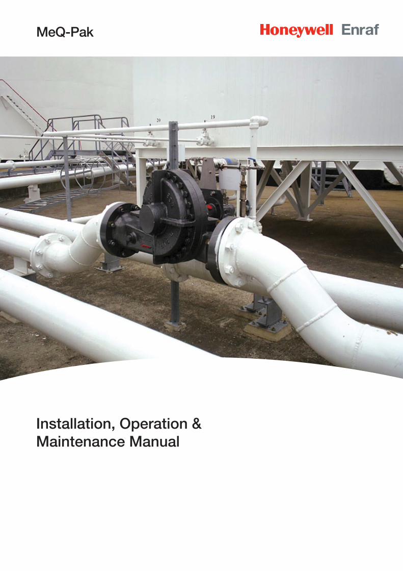
MeQ-Pak
Installation, Operation & Maintenance Manual
Table of Contents
Safety . . . . . . . . . . . . . . . . . . . . . . . . . . . . . . . . . . . . . . . . . . . . . . . . . . . . . . . . . v
Warning Note . . . . . . . . . . . . . . . . . . . . . . . . . . . . . . . . . . . . . . . . . . . . . . . . . . . v
CHAPTER 1 General Information . . . . . . . . . . . . . . . . . . . . . . . . . . . . . . . . . . . . . . . . . . . .1-1
1.1 Description of Product Function . . . . . . . . . . . . . . . . . . . . . . . . . . . . . . . . . .1-1
1.2 Applications . . . . . . . . . . . . . . . . . . . . . . . . . . . . . . . . . . . . . . . . . . . . . . . . . . .1-1
1.3 Mechanical Principles of the Assembly . . . . . . . . . . . . . . . . . . . . . . . . . . . . .1-2
1.4 Instructions for Lifting and Transport . . . . . . . . . . . . . . . . . . . . . . . . . . . . . . .1-2
1.4.1 Equipment in Un-Opened Case . . . . . . . . . . . . . . . . . . . . . . . . . . . . . . . . . . . . .1-2
1.4.2 Equipment Free of Case . . . . . . . . . . . . . . . . . . . . . . . . . . . . . . . . . . . . . . . . . .1-2
1.5 Instructions for Preservation During Transport and Storage Before and After Installation . . . . . . . . . . . . . . . . . . . . . . . . . . . . . . . . . . . . . . . . . . . .1-3
1.5.1 Preservation During Transport . . . . . . . . . . . . . . . . . . . . . . . . . . . . . . . . . . . . . .1-3
1.5.2 Equipment Finish . . . . . . . . . . . . . . . . . . . . . . . . . . . . . . . . . . . . . . . . . . . . . . . .1-3
1.6 Instructions for Unpacking, Inspection and Storage . . . . . . . . . . . . . . . . . . .1-3
1.6.1 Unpacking, Inspection . . . . . . . . . . . . . . . . . . . . . . . . . . . . . . . . . . . . . . . . . . . .1-3
1.6.2 Recommended Tools for Unpacking . . . . . . . . . . . . . . . . . . . . . . . . . . . . . . . . .1-4
1.6.3 Storage . . . . . . . . . . . . . . . . . . . . . . . . . . . . . . . . . . . . . . . . . . . . . . . . . . . . . . .1-4
1.6.4 Storage Inspection . . . . . . . . . . . . . . . . . . . . . . . . . . . . . . . . . . . . . . . . . . . . . .1-4
CHAPTER 2 Operation and Construction . . . . . . . . . . . . . . . . . . . . . . . . . . . . . . . . . . . . . .2-1
2.1 Turbine . . . . . . . . . . . . . . . . . . . . . . . . . . . . . . . . . . . . . . . . . . . . . . . . . . . . . . .2-1
2.2 MGH-1 Mechanism Assembly . . . . . . . . . . . . . . . . . . . . . . . . . . . . . . . . . . . .2-1
CHAPTER 3 Installation . . . . . . . . . . . . . . . . . . . . . . . . . . . . . . . . . . . . . . . . . . . . . . . . . . . .3-1
3.1 Installation Procedure . . . . . . . . . . . . . . . . . . . . . . . . . . . . . . . . . . . . . . . . . . .3-2
3.2 Installation Checklist . . . . . . . . . . . . . . . . . . . . . . . . . . . . . . . . . . . . . . . . . . . .3-3
CHAPTER 4 Commissioning . . . . . . . . . . . . . . . . . . . . . . . . . . . . . . . . . . . . . . . . . . . . . . . .4-1
4.1 Pump Bleeding . . . . . . . . . . . . . . . . . . . . . . . . . . . . . . . . . . . . . . . . . . . . . . . .4-1
CHAPTER 5 Maintenance . . . . . . . . . . . . . . . . . . . . . . . . . . . . . . . . . . . . . . . . . . . . . . . . . .5-1
5.1 Turbine Drive Unit . . . . . . . . . . . . . . . . . . . . . . . . . . . . . . . . . . . . . . . . . . . . . .5-1
5.2 Gearbox . . . . . . . . . . . . . . . . . . . . . . . . . . . . . . . . . . . . . . . . . . . . . . . . . . . . . .5-1
5.3 Filter . . . . . . . . . . . . . . . . . . . . . . . . . . . . . . . . . . . . . . . . . . . . . . . . . . . . . . . . .5-2
ii MeQ-Pak TDI Sept 06 Part No.: 4418200 - Revision 0 Installation, Operation & Maintenance Manual
Part No.: 4418204 - Revision 0 MeQ-Pak TDI Sept 06 iii Installation, Operation & Maintenance Manual
5.4 Check Valves . . . . . . . . . . . . . . . . . . . . . . . . . . . . . . . . . . . . . . . . . . . . . . . . . .5-2
5.5 Loading Valves . . . . . . . . . . . . . . . . . . . . . . . . . . . . . . . . . . . . . . . . . . . . . . . .5-2
5.6 Anti-syphon Valve . . . . . . . . . . . . . . . . . . . . . . . . . . . . . . . . . . . . . . . . . . . . . .5-2
5.7 Relief Valve . . . . . . . . . . . . . . . . . . . . . . . . . . . . . . . . . . . . . . . . . . . . . . . . . . .5-2
5.8 Safety of Equipment Returned for Service . . . . . . . . . . . . . . . . . . . . . . . . . .5-2
CHAPTER 6 Metering Pump Instructions . . . . . . . . . . . . . . . . . . . . . . . . . . . . . . . . . . . . . .6-1
6.1 Safety Requirements . . . . . . . . . . . . . . . . . . . . . . . . . . . . . . . . . . . . . . . . . . . .6-1
6.2 Range of Pump . . . . . . . . . . . . . . . . . . . . . . . . . . . . . . . . . . . . . . . . . . . . . . . .6-1
6.2.1 Drive Units . . . . . . . . . . . . . . . . . . . . . . . . . . . . . . . . . . . . . . . . . . . . . . . . . . . . .6-2
6.3 Operation . . . . . . . . . . . . . . . . . . . . . . . . . . . . . . . . . . . . . . . . . . . . . . . . . . . . .6-2
6.4 Pump Capacity . . . . . . . . . . . . . . . . . . . . . . . . . . . . . . . . . . . . . . . . . . . . . . . .6-3
6.5 Example . . . . . . . . . . . . . . . . . . . . . . . . . . . . . . . . . . . . . . . . . . . . . . . . . . . . . .6-3
6.6 Additive Rate Setting (Example Only) . . . . . . . . . . . . . . . . . . . . . . . . . . . . . .6-3
CHAPTER 7 Service and Inspection Schedules . . . . . . . . . . . . . . . . . . . . . . . . . . . . . . . . .7-1
7.1 Weekly . . . . . . . . . . . . . . . . . . . . . . . . . . . . . . . . . . . . . . . . . . . . . . . . . . . . . . .7-1
7.2 3-Monthly . . . . . . . . . . . . . . . . . . . . . . . . . . . . . . . . . . . . . . . . . . . . . . . . . . . . .7-1
7.3 6-Monthly . . . . . . . . . . . . . . . . . . . . . . . . . . . . . . . . . . . . . . . . . . . . . . . . . . . . .7-2
7.4 Lip Seal Fitting Instructions . . . . . . . . . . . . . . . . . . . . . . . . . . . . . . . . . . . . . .7-3
7.5 Plunger Removal and Refi tting . . . . . . . . . . . . . . . . . . . . . . . . . . . . . . . . . . . .7-4
7.5.1 Removal . . . . . . . . . . . . . . . . . . . . . . . . . . . . . . . . . . . . . . . . . . . . . . . . . . . . . .7-4
7.5.2 Reassembly . . . . . . . . . . . . . . . . . . . . . . . . . . . . . . . . . . . . . . . . . . . . . . . . . . . .7-4
7.6 Trouble Shooting . . . . . . . . . . . . . . . . . . . . . . . . . . . . . . . . . . . . . . . . . . . . . . .7-5
7.6.1 If all else fails . . . . . . . . . . . . . . . . . . . . . . . . . . . . . . . . . . . . . . . . . . . . . . . . . . .7-5
7.7 Spares and Service Kits . . . . . . . . . . . . . . . . . . . . . . . . . . . . . . . . . . . . . . . . .7-6
7.7.1 Drive Unit and Mechanisms . . . . . . . . . . . . . . . . . . . . . . . . . . . . . . . . . . . . . . . .7-6
7.7.2 Pumpheads . . . . . . . . . . . . . . . . . . . . . . . . . . . . . . . . . . . . . . . . . . . . . . . . . . . .7-6
7.8 Standard Pumphead Service Kits . . . . . . . . . . . . . . . . . . . . . . . . . . . . . . . . .7-6
7.8.1 Diaphragm Pumpheads . . . . . . . . . . . . . . . . . . . . . . . . . . . . . . . . . . . . . . . . . . .7-6
7.8.2 Plunger Pumpheads (Lip Seal) . . . . . . . . . . . . . . . . . . . . . . . . . . . . . . . . . . . . . .7-6
7.8.3 Plunger Pumpheads (Chevron/packed Seals) . . . . . . . . . . . . . . . . . . . . . . . . . .7-6
7.9 Turbine General Spares List . . . . . . . . . . . . . . . . . . . . . . . . . . . . . . . . . . . . . .7-7
7.10 Typical Commissioning Spares and Service Kits . . . . . . . . . . . . . . . . . . . . . .7-8
Table of Contents
iv MeQ-Pak TDI Sept 06 Part No.: 4418204 - Revision 0 Installation, Operation & Maintenance Manual
CHAPTER 8 Drawing/Parts List . . . . . . . . . . . . . . . . . . . . . . . . . . . . . . . . . . . . . . . . . . . . . .8-1
8.1 MeQ-Pak General Arrangement . . . . . . . . . . . . . . . . . . . . . . . . . . . . . . . . . . .8-2
8.2 MGH-1 Mechanism Assembly . . . . . . . . . . . . . . . . . . . . . . . . . . . . . . . . . . . .8-4
8.3 Metering Pumphead Type PS 4 6L 10L . . . . . . . . . . . . . . . . . . . . . . . . . . . . .8-6
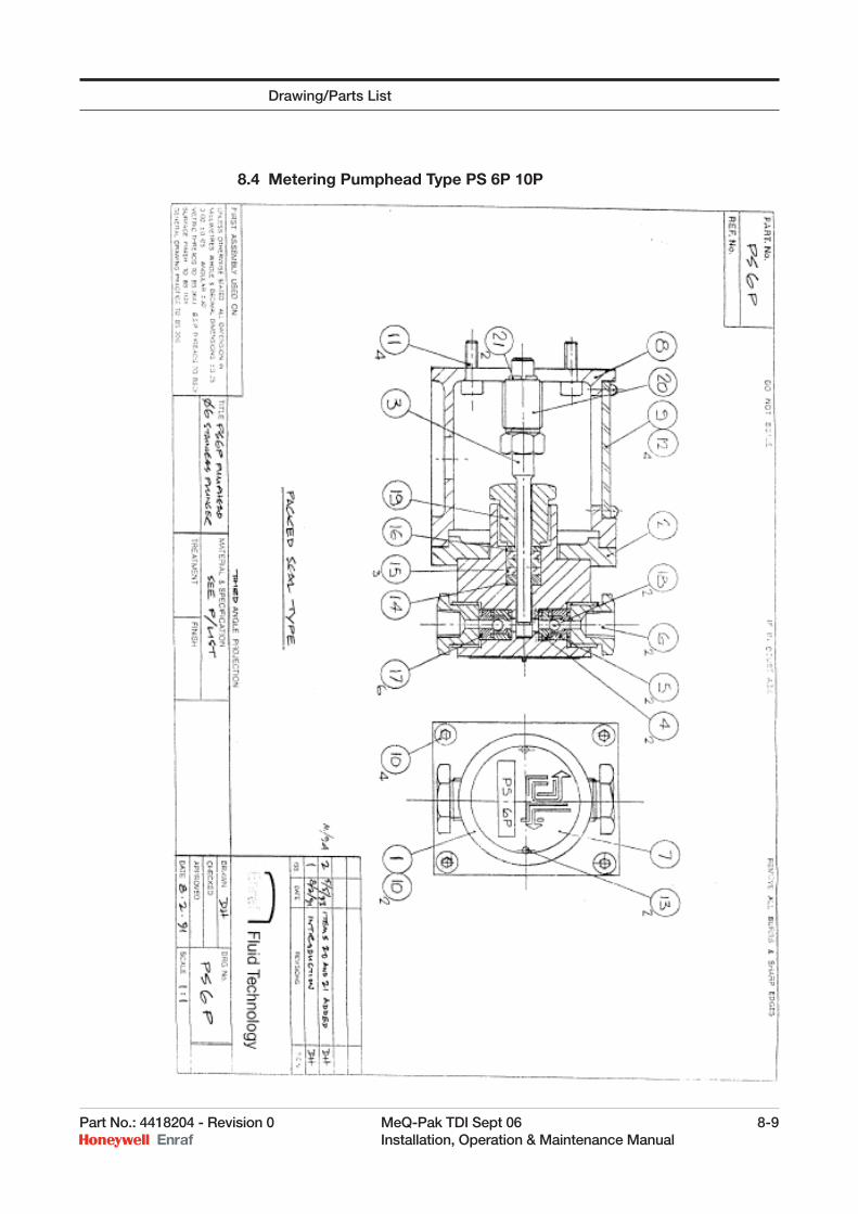
8.4 Metering Pumphead Type PS 6P 10P . . . . . . . . . . . . . . . . . . . . . . . . . . . . . .8-8
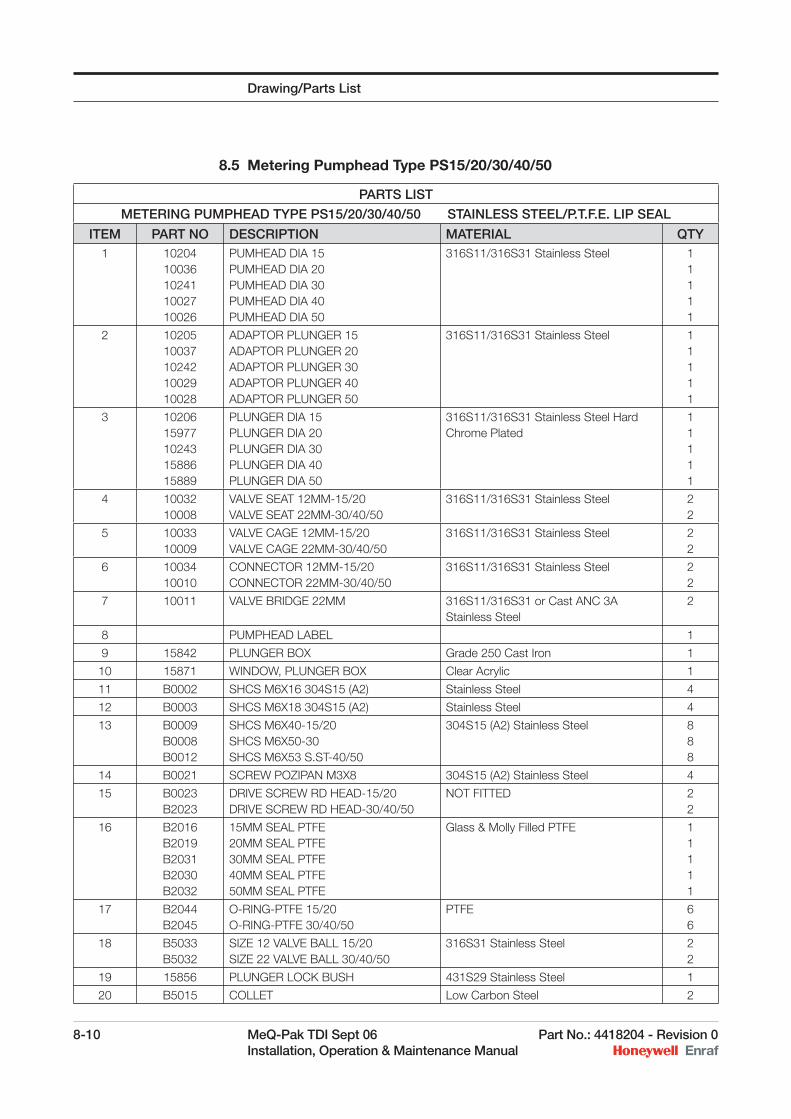
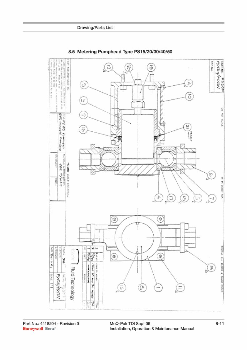
8.5 Metering Pumphead Type PS15/20/30/40/50 . . . . . . . . . . . . . . . . . . . . . . .8-10
8.6 Metering Pumphead Type PS 65 . . . . . . . . . . . . . . . . . . . . . . . . . . . . . . . . .8-12
Table of Contents
Part No.: 4418204 - Revision 0 MeQ-Pak TDI Sept 06 v Installation, Operation & Maintenance Manual
SAFETY
The following Instructions must be adhered to prior to commencement of any such work on Additive Equipment.
1) Ensure all Material Safety Data Sheets are issued and are current for additives in use.
2) Ensure all Health and Safety Procedures are adhered to and all protective clothing/equipment is clean and fully operational.
3) Ensure a copy of the handbook is available.
4) Ensure all site safety requirements are conformed to.
5) Electrical enclosures contain potentially lethal voltages. Only suitably qualifi ed personnel are to be allowed internal access.
6) Instructions provided on warning plates are to be observed at all times.
7) Ensure all wasted materials are disposed of in the correct manner.
WARNING NOTE
It will be necessary to bleed the pump(s) in accordance with instructions, but if the working pump vernier setting is low, it will be advantageous to increase the vernier setting to above 50% during the bleeding operation.
It is essential that the vernier setting is returned to its required value before the dosing system is allowed to discharge into the product.
If, when resetting the vernier, it becomes hard to turn, do not force but turn the gearbox by hexagon nut on the shaft end with a ring spanner. (or use a pump timing tool on the end pump).
Do not wind vernier below 0% or above 100%.
Never run the turbine assembly against closed valves.
Always ensure check valves removed for maintenance are reinstated in the correct orientation.
vi MeQ-Pak TDI Sept 06 Part No.: 4418204 - Revision 0 Installation, Operation & Maintenance Manual
Safety and Warning Note
Intentionally left blank.
Part No.: 4418204 - Revision 0 MeQ-Pak TDI Sept 06 1-1 Installation, Operation & Maintenance Manual
CHAPTER 1 GENERAL INFORMATION
1.1 Description of Product Function
The Enraf MeQ-Pak Self-Powered, Turbine Additive Injection Assembly has been designed and developed to permit the addition of a prescribed additive, in the correct quantity, to a main product line fl uid. This is achieved using a turbine (impeller driven by the main product fl ow) to drive, via a gearbox, pump unit(s) which supply the additive. Dependent on the requirement, the turbine to gearbox assembly can be selected from a variety of sizes (2”, 4”, 6”, 8”, 10” units), whilst one or more pump units may be used. These are also sized according to the requirement and may be used in a combination of sizes.
The MeQ-Pak ‘Turbine Driven Injector’ is capable of handling a wide range of product fl ows and can inject from as little as 0.2ppm up to 2500ppm of product. Its mechanical simplicity and rugged design will provide a reliable system requiring minimal maintenance. If necessary the turbine can be supplied as a skid assembly enabling the unit to be used as a mobile device.
Available in fi ve sizes
Self-contained with all system components ready for easy installation.
Simple and cost-effective to install.
Can be applied to any pipeline confi guration with a simple cut-in.
The turbine affords virtual free power, with high accuracy & repeatability.
Comprehensive range of options.
Turbine installation into any pipe work confi guration.
1.2 Applications
Petroleum Product
Additives
Anti-Static Additives
Corrosion Inhibitors
Aircraft Fuel Icing Inhibitors
Anti-Foam Additives
Ethyl Mercaptan
Dyes & Markers
The MeQ-Pak ‘Turbine Driven Injector’ is extremely cost effective to install, requiring only a simple pipeline cut-in, in any pipeline confi guration.
This Product is designed for use in a Zone 1 Hazardous Area.
1-2 MeQ-Pak TDI Sept 06 Part No.: 4418204 - Revision 0 Installation, Operation & Maintenance Manual
1.3 Mechanical Principles of the Assembly
The mechanical principles of the assembly are as follows:
a) An impeller, in the turbine drive unit, is driven by the fl uid being pumped through the main product supply pipe-work.
b) The impeller, in turn, drives pulsing metering pump(s) through a gearbox.
c) One stroke of the metering pump generally represents 7 or 10 revolutions of the impeller.
d) The length of stroke of the metering pump can be adjusted by means of a vernier attached to the pump stroke mechanism. A vernier setting of 100% provides the maximum stroke length and, therefore, maximum additive quantity.
e) The number of strokes of the metering pump is proportional to the impeller speed.
f) The additive pump output is proportional to the length of the pump stroke and vernier setting.
1.4 Instructions for Lifting and Transport
1.4.1 Equipment in Un-Opened CaseCase incorporates a pallet for forklift handling. Ensure orientation symbols are correct.
Forklift truck should be minimum capacity of 1 ton.
Ensure that forks completely span the pallet.
Following transportation, set down on fi rm level ground ensuring orientation symbols are correct, support/ stabilise if necessary.
1.4.2 Equipment Free of CaseNOTE: If lifting from case/pallet, follow, “Instructions for Unpacking, Inspection and Storage”.
Lift with a forklift truck or mobile crane, minimum capacity 1 ton.
Using a suitable ½ ton shackle with 1 ton strop connect to lifting eye provided on turbine case.
Lift vertically slowly.Beware: tilting due to unbalanced support. Restrain equipment from swinging and rotating do not stand or place feet below pump.
Following transport, set down on angle irons on fi rm level ground.
General Information
Part No.: 4418204 - Revision 0 MeQ-Pak TDI Sept 06 1-3 Installation, Operation & Maintenance Manual
1.5 Instructions for Preservation During Transport and StorageBefore and After Installation
1.5.1 Preservation During TransportEncased equipment should be sited on fi rm level surface and located to ensure that the case cannot be ruptured.
Ensure orientation symbols are correct.
Maximum top weight stated on the case is not exceeded.
All temporary supports for the equipment are within the casing.
Equipment is fi nished for locating in exterior environment. Additional preservation is not necessary.
1.5.2 Equipment FinishEquipment is fi nished for locating in exterior environment. Additional preservation is not necessary.
Equipment Finish
Manufacturer’s standard.
Stainless Steel - Natural
1.6 Instructions for Unpacking, Inspection and Storage
1.6.1 Unpacking, InspectionEncased equipment should be transported to the unpacking location following the recommendations given in “Instructions for Lifting and Transport”.
Ensure case is sited on fi rm level ground with correct orientation of symbols.
Inspect case. If there are signs of serious damage, advise supervisor and await instructions.
Remove top of case with claw hammer or crow bar. Safety: Remove nails from top.
Inspect contents. If there are signs of bracing/supports out of place or damage, advise supervisor and await instructions.
Remove cross bracing (if fi tted, nailed/screwed into position).
If deemed necessary, remove the case sides.
Unbolt stabilising angle irons (2 off) from the internal case beams.Note: leave angle irons attached to turbine fl anges.
To lift equipment (and transport), follow the recommendations given in, “Instructions for Lifting and Transport”.
General Information
1-4 MeQ-Pak TDI Sept 06 Part No.: 4418204 - Revision 0 Installation, Operation & Maintenance Manual
1.6.2 Recommended Tools for Unpacking Claw Hammer
Crow Bar
Nail Puller
10” Adjustable Spanner
1.6.3 StorageEquipment is constructed suitable for external location when in use.
Equipment to be stored should be sited on fi rm level ground with the lifting eye uppermost and located to minimise risk of damage to pumps and small bore piping.
The stabilising angle irons fi tted to the main fl anges (or refi tted) must be secure to prevent any possibility of toppling.
Ensure that main fl anges and small bore supply piping end are fi tted with proper blanks/plugs.
Storage preservation recommendations should be applied in accordance with “Instructions for Preservation during Transport and Storage before and after Installation”.
1.6.4 Storage InspectionEquipment in storage should be inspected every 12 months. This must include:
Removal of collected debris.
Visual Inspection of all surface conditions.
Visual inspection for external damage.
Rotation check – rotate the turbine and pumps. This can only be achieved by turning the wheel of the turbine by hand. Movement of the pump(s) is visible. Small bore piping and pumps will contain a residual amount of the testing medium – mineral oil.
NOTE: There is no known limitation of storage life.
Preparation for Use
Preparation for use after storage is recommended in:
CHAPTER 3 INSTALLATION
CHAPTER 4 COMMISSIONING
CHAPTER 6 METERING PUMP INSTRUCTIONS
General Information
Part No.: 4418204 - Revision 0 MeQ-Pak TDI Sept 06 2-1 Installation, Operation & Maintenance Manual
CHAPTER 2 OPERATION AND CONSTRUCTION
2.1 Turbine
The characteristic of the turbine assembly indicates that the fl uid being metered passes a helical chamber across which is a concentrically mounted vane impeller.
The helical chamber, formed by the two-part casing, is of uniform cross-section, and as the impeller is mounted in the centre plane, the fl uid fl ow path is inclined with respect to the impeller.
In progressing through the chamber, the fl uid also passes simultaneously through the blade area in a circumferential and axial direction.
The resultant rotation of the impeller causes each blade to traverse the conduit in an axial direction, exposing it to all fl uid velocities across the section of the conduit to give high accuracy and repeatability.
The rotational speed acquired by the impeller provides suffi cient torque at the shaft to drive, through a coupling and reduction gearbox, a number of positive displacement metering pumps.
2.2 MGH-1 Mechanism Assembly
The MGH-1 is a mechanical device that converts rotary motion of the gearbox output shaft into reciprocating motion that’s then used to drive the pumphead. The main external body of the MGH-1 is manufactured in cast iron.
The pumphead drive is through a roller bearing fi tted to a cam on the main shaft. The cam drives a hardened and ground steel crosshead with spring return. Two lengths of stroke are available. 15mm standard 7.5mm optional. Short stroke units can be mixed with long stroke unit to give a wider choice of pump outputs.
The crosshead is guided by bushes at the front and back of the casing to ensure correct alignment. The stroke length is adjusted by using a special fi ne pitch screw, operated by a “micrometer” knob that is part of the micrometer box assembly, located on the back end MGH-1. The knob is pushed in and rotated to make adjustment and released to lock in place after adjusting. The knob can be rotated through 10 turns to give full adjustment from 0 – 100%.
The actual stroke percentage setting is indicated by a digital counter in the micrometer box assembly. The stroke length can generally be adjusted either when the pump is operating or stationary. However sometimes when stationary the knob maybe diffi cult to turn, depending on the size of pump fi tted and its fi nal resting position.
A twelve tooth splined coupling system is used for initial and interconnecting drives, so that deliveries can be phased to suit specifi c
2-2 MeQ-Pak TDI Sept 06 Part No.: 4418204 - Revision 0 Installation, Operation & Maintenance Manual
process requirements. Where PS65 pumpheads are used a spacer unit is required between mechanisms.
Mechanisms, spacers and intermediate gearboxes are grease packed on assembly and no regular attention is necessary. These have a design life of 22,000 hours.
Operation and Construction
Part No.: 4418204 - Revision 0 MeQ-Pak TDI Sept 06 3-1 Installation, Operation & Maintenance Manual
CHAPTER 3 INSTALLATION
CAUTIONThe turbine assembly is only to be lifted using the lift points provided. Any other lift points used will seriously damage the assembly. Care is to be taken to ensure that no weights or undue pressures are applied to the drive gearbox, additive pump unit(s) or pipe work.
Installation of the assembly is relatively straightforward. The gearbox and pump unit(s) is mounted to one side of the turbine drive. The mounting design is such that for normal operation no further support is required once the assembly is mounted in the pipeline.
The direction of fl ow through the turbine drive unit is by-directional as indicated by an arrow cast on the side of the casing. The additive injection point is normally at the inlet end of the turbine drive unit, thus ensuring optimum mixing of the additive and product fl uids by the turbulence created through the turbine wheel. However the injection point can be positioned on either side of the turbine if required, allowing the additive to blend into the product while continuing through the pipe-work after the turbine.
A Witches hat strainer is supplied with the Turbine and should be fi tted at the inlet to the turbine. This is fabricated from 1.5mm stainless steel sheet and will need to have a gasket fi tted to both sides. Allowance for this should be made when determining the space required for fi tting the turbine into the pipeline.
NOTE: It is imperative that the turbine drive unit is installed with the metering pump plungers in a horizontal position, and the pump head inlet and outlet valves in the vertical position.
In the event that the inlet and outlet fl ange and bore sizes of the turbine drive unit do not match those of the product supply pipe work, then tapered reducers are to be fi tted both upstream and downstream of the unit. These items can be fi tted immediately adjacent to the unit.
Although the turbine drive unit is not susceptible to directional fl ow, either before the inlet or after the discharge, it is recommended that if a directional fl ow change is necessary adjacent to the unit, swept bends are used in preference to angle bends.
It is also recommended that the turbine drive unit is locally isolated to permit removal, overhaul and repair. Full bore valves should be used to achieve this.
When fi tting pump heads, care is to be taken to ensure that the delivery valve is vertically above the suction valve.
The bore of the additive supply pipe work is dependent on the following factors
a) Maximum quantity fl ow of the additive fl uid.
b) Viscosity of additive fl uid at the lowest expected temperatures.
3-2 MeQ-Pak TDI Sept 06 Part No.: 4418204 - Revision 0 Installation, Operation & Maintenance Manual
c) Minimum head from the additive fl uid storage tank.
d) Length of supply pipe work.
e) Pressure drop across any fi ttings in the supply pipe work.
3.1 Installation Procedure
Installation of the assembly will be between product line fl anges. The additive(s) supply from the storage tank(s) is connected to stainless steel pipe fi tting(s).
Access clearance to installation location will depend on the type and size of lifting/transport facility adopted.
Check suction product line for any debris.
Flush product tank discharge line to ensure that pipe is free of any debris, construction waste, scale, etc.
Flush additives supply tank discharge line(s) from storage tank to point of connection to the turbine assembly pump(s).
Dimensions, tolerances, General Arrangement Drawing MQP1/04/001.
Check fl ange to fl ange dimensions are within tolerance.
Lift assembly, (see CHAPTER 1 INSTRUCTIONS FOR LIFTING AND TRANSPORT)
Remove fl ange caps from turbine, check bore of suction and discharge for any debris.
Remove stabilising storage angles from fl anges.
Clean fl anges of assembly and product pipes.
Check rotation of turbine blades and movement of pumps.
Fit a ‘Witches Hat Strainer’ in the inlet of the MeQ-Pak. A gasket is required on both sides of the strainer.
Locate assembly between pipeline fl anges.
Insert gasket(s)
Insert fl ange bolts and fi t nuts.
Tighten up bolts progressively by rotation around fl ange, operating on diametrically opposite bolts in turn.
Remove plug(s) from pump suction line(s).
Connect the additives tank(s) discharge line(s) to the appropriate pump suction fi tting.
WARNING: A protection device needs to be fi tted in the pipeline to prevent inadvertent over pressurisation of the MeQ-Pak. This device should also protect the MeQ-Pak from over pressurisation from external fi re.
!
Installation
Part No.: 4418204 - Revision 0 MeQ-Pak TDI Sept 06 3-3 Installation, Operation & Maintenance Manual
3.2 Installation Checklist
Assembly is correct for the location.
Flange sizes and type are matched.
Product line has been fl ushed and cleared of debris.
Turbine assembly is clear of debris. Assembly is free to rotate.
Flange faces are clean.
Gaskets are fi tted.
All fl ange bolts are fi tted and have been tightened evenly.
Additive tank discharge line(s) have been fl ushed.
Additive tank discharge lines are connected to the turbine pump(s) suction line(s).
Flange joints are secure.
Small bore joints arc secure.
Ensure that all injection pumps are provided with a fl ooded suction at all times. Plunger pumps will be damaged if run dry.
If a calibration jar is fi tted the vent on top of the calibration jar should be piped so that the top of the vent is higher than the top of the additive supply tank if possible.
Installation
3-4 MeQ-Pak TDI Sept 06 Part No.: 4418204 - Revision 0 Installation, Operation & Maintenance Manual
Intentionally left blank.
Installation
Part No.: 4418204 - Revision 0 MeQ-Pak TDI Sept 06 4-1 Installation, Operation & Maintenance Manual
CHAPTER 4 COMMISSIONING
On the successful installation of the assembly, commissioning can take place.
CAUTIONThe isolation hand valve, located in the discharge pipe between additive pump and the turbine, must be to OPEN position before the assembly is operated for additive purposes.
NOTE: Before operating the assembly ensure that the additive storage tank is full and all supply valves are open.
WARNING: SAFETY MEASURES CONCERNING THE PRODUCTS BEING USED IN THE MAIN PIPELINE AND THE ADDITIVE PIPELINE SHOULD BE STRICTLY ADHERED TO. REFER TO THE ADDITIVE MATERIAL SAFETY DATA SHEET (MSDS) FOR HEALTH AND SAFETY INFORMATION.
WARNING: The pump vernier setting is 0 - 100%.NEVER adjust the vernier below 000 or above 100. Any fi gure below 000 or above 100 should be ignored as it will be ineffective and will cause severe damage to the pump mechanism.
4.1 Pump Bleeding
NOTE: Refer to the MSDS for the additive and take the appropriate measures to contain any spillages. This should be kept to a minimum.
Each pump has a check valve set a 1 bar on it discharge. This is fi tted to stop additive fl owing through the pump under gravity.
All the additive pumps should be bled before commencing operation. Proceed as follows:
1. Open up the additive supply from the storage tank and vent the supply line if possible.
2. Loosen the output pipe work at the pump delivery valve below the check valve mounted on the pump assembly head. (4 bolts PS15 – PS65) (Hex PS6 – PS10)
3. Gravity must be enough to bleed the pumps otherwise pumping problems will occur. Bleed the pumps until a free fl ow of additive is seen to be fl owing from the pump delivery valve below the check valve.
4. Retighten the pipe work.
5. If a fl owmeter has been fi tted refer to the fl owmeter manual for commissioning instructions.
6. If a calibration point has been fi tted in the pump discharge, this can be used to bleed the pipe-work up to this point with the pumps running.
!
!
4-2 MeQ-Pak TDI Sept 06 Part No.: 4418204 - Revision 0 Installation, Operation & Maintenance Manual
Intentionally left blank.
Commissioning
Part No.: 4418204 - Revision 0 MeQ-Pak TDI Sept 06 5-1 Installation, Operation & Maintenance Manual
CHAPTER 5 MAINTENANCE
The maintenance aspects of the assembly are described separately under each major component.
WARNING: SAFETY MEASURES CONCERNING PRODUCTS BEING USED IN THE MAIN PIPELINE AND THE ADDITIVE PIPELINE SHOULD BE STRICTLY ADHERED TO.REFER TO THE ADDITIVE MATERIAL SAFETY DATA SHEET (MSDS) FOR HEALTH AND SAFETY INFORMATION.
5.1 Turbine Drive Unit
No service is required to the turbine drive unit. However, periodic checks should be made during normal operating conditions to check for mechanical seal failure. A telltale hole is drilled in the mounting spool between the turbine housing and the gearbox for this purpose.
In the event that the mechanical seal should require replacement, proceed as follows:
1. Close the isolation valves, situated on each side of the turbine.
2. Drain the turbine drive unit.
3. Disconnect the necessary pipes from the pump(s).
4. Remove the pumps and gearbox.
5. Remove the half-coupling from the turbine shaft.
6. Remove eight bolts holding the spool piece to the turbine case and remove the spool spice and stationary seal holder.
7. Refer to the instructions with the mechanical seal for fi tting.New nyloc grub screws are to be used in the coupling, and a new O ring fi tted between the spool piece and the stationary seal holder.
8. After seal replacement, follow the above instructions in reverse order to re-assemble.
9. Follow the pump bleeding procedure before putting the unit back into service.
NOTE: It is recommended that the turbine case assembly is pressure tested following seal replacement to ensure correct installation. Also depending on the age of the turbine and the work load it has been subjected to, consideration for a complete overall may be need. The turbine will need to be removed from the pipeline for this to be carried out.
5.2 Gearbox
The gearbox is oil fi lled and is sealed for life. No maintenance is required, however it should be periodically inspected and the unit should be replaced if defective.
!
5-2 MeQ-Pak TDI Sept 06 Part No.: 4418204 - Revision 0 Installation, Operation & Maintenance Manual
5.3 Filter
A fi lter is fi tted into the additive supply line and requires regular 3 monthly inspections.
5.4 Check Valves
EFT Check valves are used for the following.
5.5 Loading Valves
A stainless steel loading valve is fi tted to each pumphead to ensure that the pumphead is continuously charged with the correct amount of injection fl uid from a fl ooded suction. However, it will hold any excess pressure between the additive head and the product pressure. This valve will normally be set at 1 bar.
5.6 Anti-syphon Valve
The injection point is fi tted with a stainless steel anti-syphon valve. This valve is normally set at 3 bar, and prevents additive being drawn into the system by vacuum, or any venturi effect created when the system is run and additive is not required.
5.7 Relief Valve
Each additive system is fi tted with a stainless steel relief valve. These valves can be piped either back to the pump suction or back to the additive tanks. They will normally be set at 15bar. If the relief valve returns back to the pump suction (normal confi guration) then an open, non restrictive line should be maintained to and from the supply tank.No check valves fi tted in this supply line.
CAUTIONExtreme care should be taken maintaining the check valves as any failure could result in the incorrect mixing of additive into the product line or vice versa.
5.8 Safety of Equipment Returned for Service
In the event of any equipment being returned for service, the following points are to be noted:
a) All pumps and accessories returned are to be in a clean and safe condition.
b) Details of all the fl uids that have been pumped including cleaning and fl ushing must be clearly marked on a label tied to the unit and a MSDS for each must be provided.
c) Action to be taken in the event of inadvertent contact with any residual fl uid is also to be advised.
Maintenance
Part No.: 4418204 - Revision 0 MeQ-Pak TDI Sept 06 6-1 Installation, Operation & Maintenance Manual
CHAPTER 6 METERING PUMP INSTRUCTIONS
6.1 Safety Requirements
Read this section before carrying out any work on the EFT Metering Pump.
The pump must be installed, operated and maintained in accordance with this manual.
Do not run the pump against closed valves or blocked delivery lines. Failure to comply with this precaution will result in damage to the pump or its associated equipment with the possibility of personal injury.
All chemicals, mixtures and pumped media must be handled strictly in accordance with their manufacturer’s instructions. Any harmful liquids must not come into contact with operators or other personnel. Refer to Material Safety Data Sheet MSDS.
Before carrying out any work on a metering pump:
1. It must be stopped and electricity/mechanically isolated. (Product pump)
2. Harmful products must be fl ushed out of the system.
6.2 Range of Pump
On EFT Turbine unit all pumps are mounted onto a MGH1 Mechanism. (see CHAPTER 2).
This metering pump has been designed as a robust, adaptable and powerful tool for accurate metered pumping of various media.
A wide standard range of mechanisms/pumpheads are available in stainless steel construction with a choice of seals. (PTFE are standard)
Plunger pumpheads are available in 6mm, 10mm, 15mm, 20mm, 30mm, 40mm and 50mmand 65mm diameters.
Hydraulic Diaphragm pumpheads are available in 6mm, 10mm, 20mm and 30mm diameters. All diaphragms are made from PTFE.
Multiple pumpheads may be fi tted and interconnected to give fl ow with reduced pulsations. Each additional pumphead requires a “mechanism” to give stroke control and mechanisms can be bolted directly together when using plunger pumpheads.(If a PS65 is used then a spacer is also required to allow for the width of the pumphead).
The standard stroke length of all pumps is 15mm except for the 50mm diaphragm pump which has a stroke length of 7.5mm. If required 7.5mm stroke units are available as an option on all pumps.
6-2 MeQ-Pak TDI Sept 06 Part No.: 4418204 - Revision 0 Installation, Operation & Maintenance Manual
Flow ranges from 0.45 litres /hour to 295 litres /hour (0.09 - 65gph) and maximum discharge pressure from 12 bar to 680 bar. (175 - 10,000psi). Relief valves are normally set at 15bar. Some seal arrangements do not allow maximum pressure to be achieved.
Variation in pump output is achieved by setting a digital “micrometer”. The micrometer has a adjustable scale that reads 0 – 999,however this should only be operated between 0 – 100. This represents the appropriate percentage of full stroke length (or output). Generally pump performance will remain linear from 10% to 100% although diaphragm pumpheads will not operate to the same high accuracy as plunger pumpheads.
Pumps may be ganged to give full use of power available and to allow for the pumping of “cocktails” to suit the user’s process. A maximum of nine pumpheads may be fi tted to a single drive unit and full rated pressure is available with up to three pumpheads suitable phased. When more than three pumpheads are fi tted, maximum pressure has to be de-rated.
For further information, please contact Enraf Fluid Technology Ltd.
6.2.1 Drive UnitsMechanisms, spacers and intermediate gearboxes are grease packed on assembly and no regular attention is necessary. These have a design life of 22,000 hours.
6.3 Operation
NOTE: Running the turbine is required to operate the pumps. As this will require the transfer/movement of product this should be organised and controlled by site staff.Ensure that all safety instructions in this handbook and those from manufacturers of pumped media, etc are followed implicitly.
Ensure compliance with all system design and operation requirements.
Check that there are no closed valves in the delivery line.
Bleed the pumps.
Start the pump. Remember that the pumps with low outputs may take some time to fi ll a system. If liquid fl ow is not detected, stop the pump, re-vent and try starting again. Repeat as necessary. (Set up the micrometer to 100% to assist start-up).
Adjust the micrometer to obtain the required output from the pump. Push in the micrometer knob and rotate until the desired percentage of output is shown in the window. Release the knob and allow it to spring back and lock in position. See pump data sheet for the output of a specifi c pump at 100% stroke setting. (All pumps are tested on water at the manufactures with a slave motor. It is likely that pump performance will improve during the fi rst few hours/days of service as valves and seals “bed in”).
Metering Pump Instructions
Part No.: 4418204 - Revision 0 MeQ-Pak TDI Sept 06 6-3 Installation, Operation & Maintenance Manual
NOTE: As the EFT METERING pump is capable of delivering high pressure, it is not always possible to adjust the stroke length when the drive unit is stationary.
6.4 Pump Capacity
The pump(s) capacity is to be checked every three months or as required by site specifi cations. It can be checked against the meter, if fi tted. The unit and the meter can be checked against a measuring vessel. A sample point is fi tted after the fl ow meter. It is recommended that the pump vernier(s) are set to 100% during the test and the pump(s) strokes per minute counted during the test period. The quantity fl ow should be in accordance with the pump(s) output given below:
6.5 Example
1 in number PS 50 pump.
Strokes per minute during test - 75 (counted).
Duration of tests – 1 minute.
Quantity fl ow – 2.0litres.
1 X PS 50 delivers 160 litres/hour at 100% strokes at 100 strokes/minute. (Nominal)
1 X PS 50 delivers 120 litres/hour at 100% strokes at 75 strokes/minute. (Nominal)
The pumps should give 2.0 litres ± 1% in 1 minute.
After the test reset the vernier to the required setting.
6.6 Additive Rate Setting (Example Only)
NOTE: When performing this calculation it is essential that the client refers to the individual pump(s) calibration data. Pump strokes/min should be counted for a known product fl ow rate. Nominal fi gures are shown below.
In order to establish the vernier setting for the assembly, proceed as follows:
a) Check turbine size and pump confi guration.
b) Measure turbine speed against a constant fl ow rate i.e. a 10” unit will have a turbine speed of 645 RPM @ 800 M3/hour.
c) Check gearbox ratio i.e. 7:1.
d) Pump strokes per minute @ 800 M3/hour will be 92 optimum.
e) Dosing rate required = ppm x Product Flow rate (lph) = Litres per hour
1000000
Metering Pump Instructions
6-4 MeQ-Pak TDI Sept 06 Part No.: 4418204 - Revision 0 Installation, Operation & Maintenance Manual
For 340 ppm = 340 x 800000 = 272 L.P.H
1000000
f) Pump output PS 50 @ 100 s.p.m = 160 L.P.H
g) Pump output 2 x PS 50 @ 100 s.p.m = 320 L.P.H
h) Pump output 2 x PS 50 @ 92 s.p.m = 294 L.P.H
i) Vernier Setting 272 x 100 = 92%
294
Metering Pump Instructions
Part No.: 4418204 - Revision 0 MeQ-Pak TDI Sept 06 7-1 Installation, Operation & Maintenance Manual
CHAPTER 7 SERVICE AND INSPECTION SCHEDULES
1 Refer to the relevant Material Safety Data Sheets (MSDS) for both the additive and the product before starting work. Adhere to all the necessary safety requirements.
2 Special Equipment Clean protective clothing - gloves, goggles required.
NOTE: Protective clothing must be full - no short sleeves.Safety glasses do not give suffi cient protection.
3 Operational interference Dosing facilities out of service.
4 Tools Required Hand Tools.
5 Cleanliness High standard essential.
6 Materials Required Cleaning cloths (Clean only with a damp cloth).
7.1 Weekly
Visually inspect turbine unit and installation, Checking for:-
1 Suffi cient additive in the supply tank.
2 Leaks on pipe-work between supply tank and turbines.
3 Leaks from turbine pumps and associated pipe-work.
4 Turbine is turning when product is fl owing.
5 Pumps are stroking to full setting.
6 Meter is operating. (If fi tted)
7 No additional noise from turbine.
8 No additional noise from pumps.
NOTE: If any concern is felt on 3 to 8 investigate problem and rectify as necessary.
9 Check meter reading (if fi tted) and quantify dosing rate against product fl ow. If not in accordance with required setting, liaise with site staff and investigate the problem and rectify as necessary.
7.2 3-Monthly
1 Carry out weekly routine.
2 Check meter reading (If fi tted) and quantify dosing rate against product fl ow. Investigate if the readings show that the turbine unit isn’t operating as required.
7-2 MeQ-Pak TDI Sept 06 Part No.: 4418204 - Revision 0 Installation, Operation & Maintenance Manual
3 Check tightness of all pump heads, assembly nuts, bolts and screws.
4 Check tightness of holding down bolts of the gearbox and pumps.
5 FILTER - Check cleanliness of additive supply fi lter by removing the element. Wash out in suitable solvent and replace. If seal or joint is damaged, replace with new.
6 Remove guard over coupling between the gearbox and the fi rst pump and inspect for damage. Replace coupling if required then ensure that it is operating smoothly. Replace guard.
7.3 6-Monthly
1 Carry out weekly and 3-monthly routines.
2 With unit running, check all valves, unions and pipe lines for leaks.
3 TURBINE DRIVE UNIT - Using the tell-tale hole (in the spool piece between the turbine housing and the gearbox, and capped with a red plug), check for seal failure (in the event of seal failure, see instruction manual, maintenance section or call in Enraf Fluid Technology Ltd.).
4 PUMP UNIT(S) - Clean down metering pump(s) and inspect the pumphead(s) for any leakages at the plunger gland.
5 If the plunger gland/seal appears to be leaking,i If a packing gland is fi tted, (PS6 & PS10) try to tighten the gland and
see if this stops the leak. If not repack the gland.ii If a lip seal is fi tted this will need to be replaced. (see instruction
manual, maintenance section or call in Enraf Fluid Technology Ltd.).
NOTE: If the gland/seal needs to be replaced the plunger should also be inspected for any damage and replaced as necessary.
6 METER – Check the meter by using the appropriate size calibration jar. Log check fi gures in appropriate record.
NOTE: This is not an approved fi scal check and will only give an indication that the fl ow-meter is working correctly. Should an approved calibration be required, the fl ow-meter will need to be removed from the turbine assembly and sent to an approved fl owmeter test/calibration house.
Service and Inspection Schedules
Part No.: 4418204 - Revision 0 MeQ-Pak TDI Sept 06 7-3 Installation, Operation & Maintenance Manual
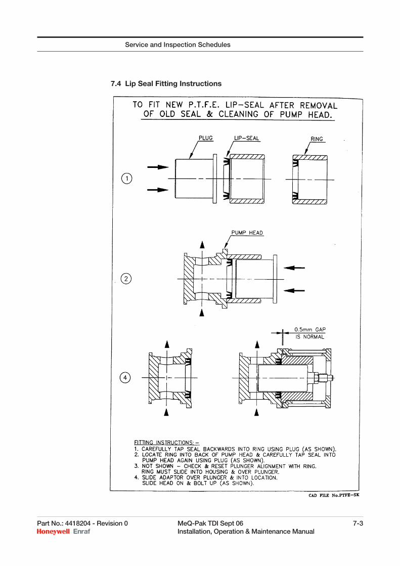
7.4 Lip Seal Fitting Instructions
Service and Inspection Schedules
7-4 MeQ-Pak TDI Sept 06 Part No.: 4418204 - Revision 0 Installation, Operation & Maintenance Manual
7.5 Plunger Removal and Refi tting
To remove plunger this will require the suction and discharge pipe-work to be disconnected from the pumphead and the pumphead removed from the pump assembly. The turbine should be made safe in accordance with site requirements before any maintenance work is started.
7.5.1 Removal1. Isolate the turbine unit so that it can’t start.
2. Refer to the relevant Material Safety Data Sheets for both the additive and the product before starting work. Adhere to all the necessary safety requirements.
3. Isolate the additive supply.
4. Shut the additive supply valve at the turbine injection point.
5. Disconnect the additive supply and discharge pipe-work from the pumphead. Use an appropriate container to catch any additive and then plug the pipe-work to stop any drips.
6. Remove the pumphead carefully from the plunger box.
7. Remove window from top of plunger box.
8. Using 17mm A/F spanner through window hole, undo and remove plunger. DO NOT REMOVE PLUNGER BOX.
9. Inspect plunger. If scored in area of seal operation, it must be replaced.
7.5.2 Reassembly1. Remove plunger nut and split collets from drive end of plunger.
2. Slide plunger nut back up new plunger and fi t collets back into groove, smallest diameters towards plunger nut. Space collets equally around shaft and slide plunger nut over collets. Tap the cullet end of the plunger gently on a fi rm surface to hold in position on the shaft. This will assist with the assembly when connecting onto the cross-head on the Mech.
3. Locate end of plunger into cross head and tighten plunger nut through window hole. Be careful not to disturb the collets on the plunger.
4. When the nut is tight, loosen it slightly and tap the end of the plunger with a copper or leather hammer to free the collets.
5. Using a plunger centring ring over the plunger and, located in the front face of the plunger box, nip up plunger nut and check that ring slides freely in and out. If the ring remains free, plunger is in correct position.
6. It is likely that plunger will not be in correct position at fi rst attempt. If this is the case, slacken plunger nut slightly and tap end of plunger with copper or leather hammer to free collets. Twist plunger back and forth and try re-tightening. Check position with centring ring.
Service and Inspection Schedules
Part No.: 4418204 - Revision 0 MeQ-Pak TDI Sept 06 7-5 Installation, Operation & Maintenance Manual
7. Repeat this operation until plunger is central and then fully tighten plunger nut; re-check again. When centring ring slides easily in and out of plunger box, the plunger is in correct position.
NOTE: If plunger is not central, chevron seals and lip seals (particularly PTFE/carbon PTFE) will only last a few hours in service.
8. Refi t pump head and associated pipe-work.
9. De-isolate and reinstate pump in system according to operating position.
10. Remove the isolation from the turbine. Operate the turbine and monitor the pump for any leaks during its fi rst few minutes of running and then on regular basis until you are satisfi ed that the pump is running correctly.
NOTE: Running the turbine is required to operate the pumps. As this will require the transfer/movement of product this should be organised and controlled by site staff.Ensure that all safety instructions in this handbook and those from manufacturers of pumped media, etc are followed implicitly.
7.6 Trouble Shooting
In the unlikely event of the pump not operating correctly, refer to this section. Before working on the pump, observe the “Safety Requirements” section.
Check that the suction strainer, if fi tted, is not blocked. If so, clean out the element. Ensure that the suction line isolating valve is open.
Suction hose check that it is not collapsing under the operating conditions.
Increase the stroke setting to 100% to improve the start-up/venting performance.
Ensure that any air collecting in the delivery pipe-work is vented. Pumps will not prime or run if air locked. This is particularly important for 6mm and 10mm plunger pumpheads.
If the pump has been installed with a suction lift (never recommended) try raising the supply tank, or using any other safe method to wet the pumphead and valve gear.
Check for seal leakage. If the seal allows liquid to pass out of the pump, it will allow air into the pumphead on suction stroke. Replace the seal or diaphragm if leakage is occurring.
Sometimes loose particles lodge on the suction valve seat causing temporary loss of pumping. Tap the pumphead fi rmly with a hide mallet or similar tool - this will often solve the problem.
7.6.1 If all else failsConsider attention to the valve gear. Check for any blockage or foreign matter (swarf from pipework, etc) trapped at the valve seats and clean it
Service and Inspection Schedules
7-6 MeQ-Pak TDI Sept 06 Part No.: 4418204 - Revision 0 Installation, Operation & Maintenance Manual
off. Inspect the seating faces; if damaged, replace the seals and balls. Re-assemble carefully - see the pumphead drawing for details.
If the valve gear is re-assembled incorrectly, a hydraulic lock may occur and cause major damage to the pump.
7.7 Spares and Service Kits
7.7.1 Drive Unit and MechanismsA sectional drawing is enclosed for reference purposes only. Special tools are required for dismantling and re-assembly. Contact Enraf Fluid Technology Ltd.
7.7.2 PumpheadsAll pumpheads have a type number shown on the front label. Always quote this number when ordering spare parts. Please also quote Turbine serial number.
Refer to the relevant pumphead drawing and quoted ballooned item numbers as required, together with the description from its parts list.
7.8 Standard Pumphead Service Kits
7.8.1 Diaphragm Pumpheads1 x diaphragm
2 x valve seats
2 x valve balls
6 x “O” rings
7.8.2 Plunger Pumpheads (Lip Seal)1 x lip seal (including back-up ring, if necessary)
2 x valve seats
2 x valve balls
6 x “O” rings
7.8.3 Plunger Pumpheads (Chevron/packed Seals)3 x chevron rings or
1 set packing rings & anti-extrusion rings
2 x valve seats
2 x valve balls
6 x “O” rings
Service and Inspection Schedules
Part No.: 4418204 - Revision 0 MeQ-Pak TDI Sept 06 7-7 Installation, Operation & Maintenance Manual
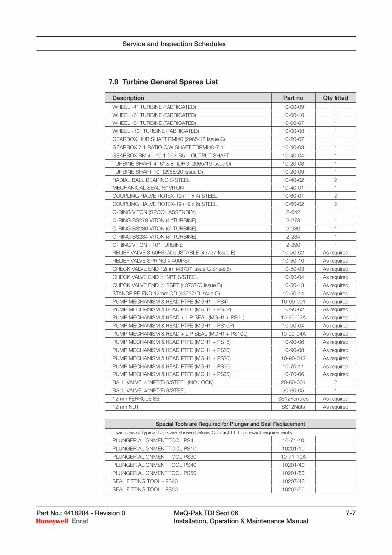
7.9 Turbine General Spares List
Description Part no Qty fi tted
WHEEL -4” TURBINE (FABRICATED) 10-00-09 1
WHEEL -6” TURBINE (FABRICATED) 10-00-10 1
WHEEL -8” TURBINE (FABRICATED) 10-00-07 1
WHEEL -10” TURBINE (FABRICATED) 10-00-08 1
GEARBOX HUB SHAFT RMI40 (2965/18 Issue C) 10-20-07 1
GEARBOX 7:1 RATIO C/W SHAFT TDRMI40-7:1 10-40-03 1
GEARBOX RMI40-10:1 D63-B5 + OUTPUT SHAFT 10-40-04 1
TURBINE SHAFT 4” 6” & 8” (DRG: 2965/19 Issue D) 10-20-08 1
TURBINE SHAFT 10” (2965/20 Issue D) 10-20-09 1
RADIAL BALL BEARING S/STEEL 10-40-02 2
MECHANICAL SEAL ½” VITON 10-40-01 1
COUPLING HALVE ROTEX-19 (11 x 4) STEEL 10-60-01 2
COUPLING HALVE ROTEX-19 (19 x 6) STEEL 10-60-02 2
O-RING VITON (SPOOL ASSENBLY) 2-042 1
O-RING BS278 VITON (4 “TURBINE) 2-278 1
O-RING BS280 VITON (6” TURBINE) 2-280 1
O-RING BS284 VITON (8” TURBINE) 2-284 1
O-RING VITON - 10” TURBINE 2-390 1
RELIEF VALVE 3-50PSI ADJUSTABLE (43737 Issue E) 10-50-02 As required
RELIEF VALVE SPRING 4-400PSI 10-50-10 As required
CHECK VALVE END 12mm (43737 Issue G Sheet 5) 10-50-03 As required
CHECK VALVE END ½”NPT S/STEEL 10-50-04 As required
CHECK VALVE END ½”BSPT (43737/C Issue B) 10-50-13 As required
STANDPIPE END 12mm OD (43737/D Issue C) 10-50-14 As required
PUMP MECHANISM & HEAD PTFE (MGH1 + PS4) 10-90-001 As required
PUMP MECHANISM & HEAD PTFE (MGH1 + PS6P) 10-90-02 As required
PUMP MECHANISM & HEAD + LIP SEAL (MGH1 + PS6L) 10-90-02A As required
PUMP MECHANISM & HEAD PTFE (MGH1 + PS10P) 10-90-04 As required
PUMP MECHANISM & HEAD + LIP SEAL (MGH1 + PS10L) 10-90-04A As required
PUMP MECHANISM & HEAD PTFE (MGH1 + PS15) 10-90-06 As required
PUMP MECHANISM & HEAD PTFE (MGH1 + PS20) 10-90-08 As required
PUMP MECHANISM & HEAD PTFE (MGH1 + PS30) 10-90-012 As required
PUMP MECHANISM & HEAD PTFE (MGH1 + PS50) 10-70-11 As required
PUMP MECHANISM & HEAD PTFE (MGH1 + PS65) 10-70-06 As required
BALL VALVE ½”NPT(F) S/STEEL (NO LOCK) 20-60-001 2
BALL VALVE ¼”NPT(F) S/STEEL 20-60-05 1
12mm FERRULE SET SS12Ferrules As required
12mm NUT SS12Nuts As required
Special Tools are Required for Plunger and Seal Replacement
Examples of typical tools are shown below. Contact EFT for exact requirements.
PLUNGER ALIGNMENT TOOL PS4 10-71-10
PLUNGER ALIGNMENT TOOL PS10 10201/10
PLUNGER ALIGNMENT TOOL PS30 10-71-10A
PLUNGER ALIGNMENT TOOL PS40 10201/40
PLUNGER ALIGNMENT TOOL PS50 10201/50
SEAL FITTING TOOL - PS40 10207/40
SEAL FITTING TOOL - PS50 10207/50
Service and Inspection Schedules
7-8 MeQ-Pak TDI Sept 06 Part No.: 4418204 - Revision 0 Installation, Operation & Maintenance Manual
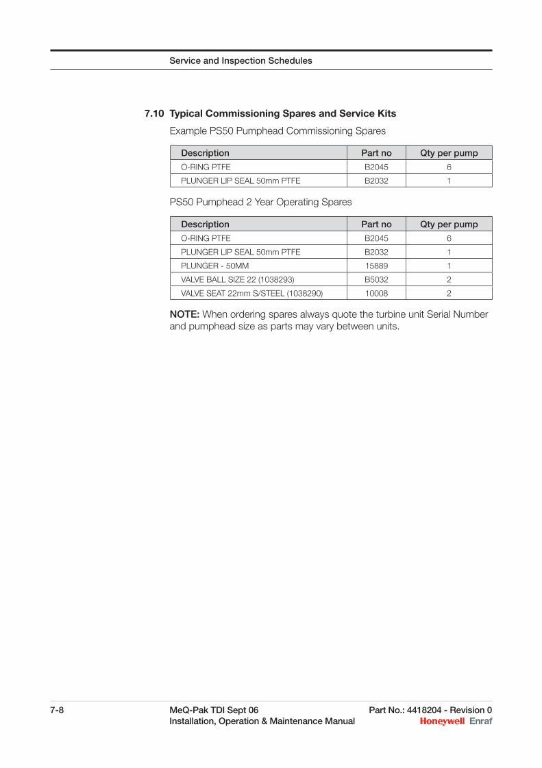
7.10 Typical Commissioning Spares and Service Kits
Example PS50 Pumphead Commissioning Spares
PS50 Pumphead 2 Year Operating Spares
NOTE: When ordering spares always quote the turbine unit Serial Number and pumphead size as parts may vary between units.
Description Part no Qty per pump
O-RING PTFE B2045 6
PLUNGER LIP SEAL 50mm PTFE B2032 1
Description Part no Qty per pump
O-RING PTFE B2045 6
PLUNGER LIP SEAL 50mm PTFE B2032 1
PLUNGER - 50MM 15889 1
VALVE BALL SIZE 22 (1038293) B5032 2
VALVE SEAT 22mm S/STEEL (1038290) 10008 2
Service and Inspection Schedules
Part No.: 4418204 - Revision 0 MeQ-Pak TDI Sept 06 8-1 Installation, Operation & Maintenance Manual
CHAPTER 8 DRAWING/PARTS LIST
Drawing Ref.
MQP1/04/001 TURBINE GENERAL ARRANGEMENT
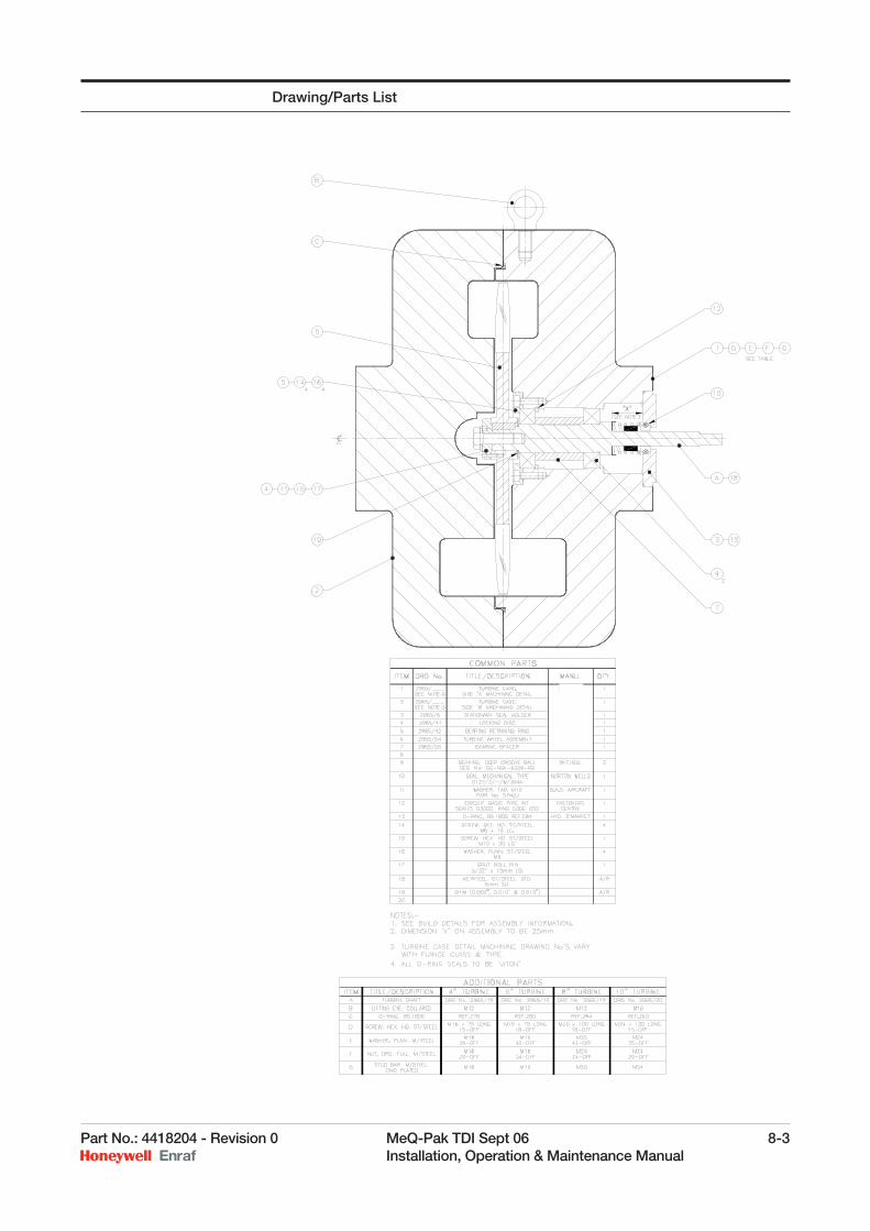
2965/51 4” 6” 8” & 10” TURBINE CASE ASSEMBLY
MGH-1 MECHANISM ASSEMBLY & Parts List
METERING PUMPHEAD TYPE PS 4 6L 10L & Parts List
METERING PUMPHEAD TYPE PS 6P 10P & Parts List
METERING PUMPHEAD TYPE PS15/20/30/40/50 & Parts List
METERING PUMPHEAD TYPE PS 65 & Parts List
8-2 MeQ-Pak TDI Sept 06 Part No.: 4418204 - Revision 0 Installation, Operation & Maintenance Manual
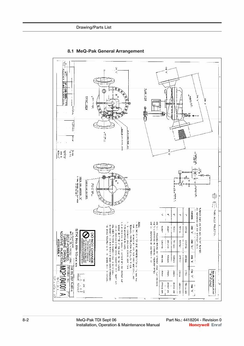
8.1 MeQ-Pak General Arrangement
Drawing/Parts List
Part No.: 4418204 - Revision 0 MeQ-Pak TDI Sept 06 8-3 Installation, Operation & Maintenance Manual
Drawing/Parts List
8-4 MeQ-Pak TDI Sept 06 Part No.: 4418204 - Revision 0 Installation, Operation & Maintenance Manual
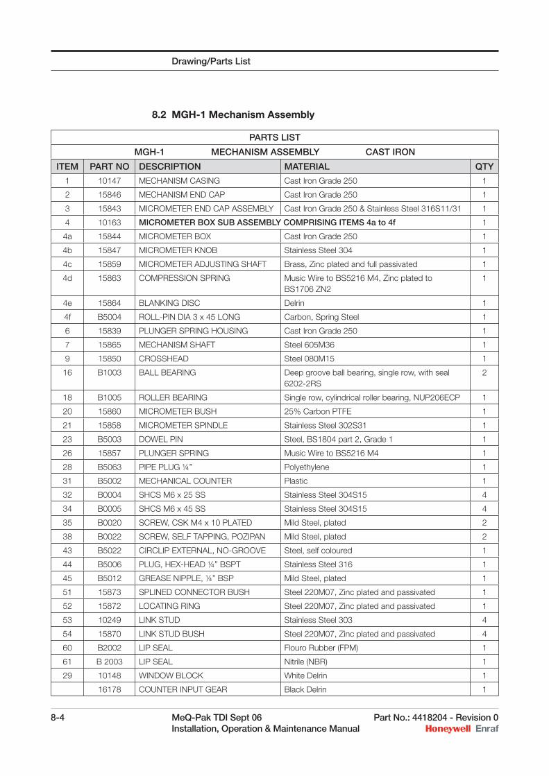
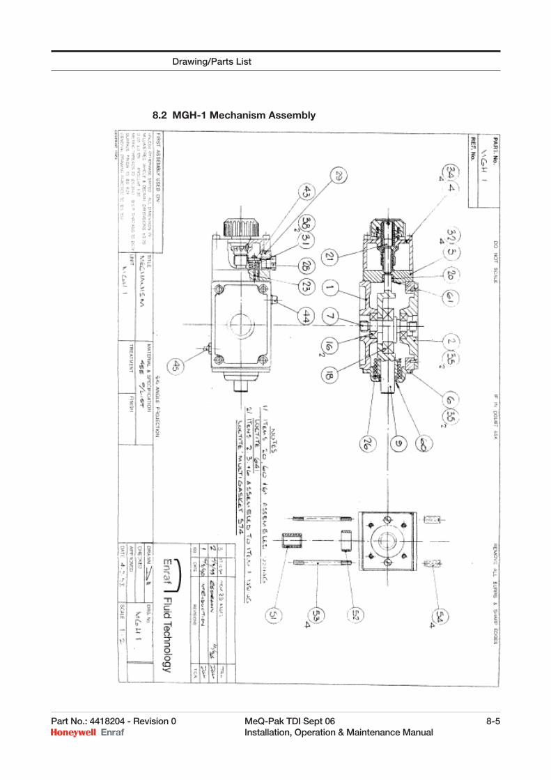
8.2 MGH-1 Mechanism Assembly
PARTS LIST
MGH-1 MECHANISM ASSEMBLY CAST IRON
ITEM PART NO DESCRIPTION MATERIAL QTY
1 10147 MECHANISM CASING Cast Iron Grade 250 1
2 15846 MECHANISM END CAP Cast Iron Grade 250 1
3 15843 MICROMETER END CAP ASSEMBLY Cast Iron Grade 250 & Stainless Steel 316S11/31 1
4 10163 MICROMETER BOX SUB ASSEMBLY COMPRISING ITEMS 4a to 4f 1
4a 15844 MICROMETER BOX Cast Iron Grade 250 1
4b 15847 MICROMETER KNOB Stainless Steel 304 1
4c 15859 MICROMETER ADJUSTING SHAFT Brass, Zinc plated and full passivated 1
4d 15863 COMPRESSION SPRING Music Wire to BS5216 M4, Zinc plated to BS1706 ZN2
1
4e 15864 BLANKING DISC Delrin 1
4f B5004 ROLL-PIN DIA 3 x 45 LONG Carbon, Spring Steel 1
6 15839 PLUNGER SPRING HOUSING Cast Iron Grade 250 1
7 15865 MECHANISM SHAFT Steel 605M36 1
9 15850 CROSSHEAD Steel 080M15 1
16 B1003 BALL BEARING Deep groove ball bearing, single row, with seal 6202-2RS
2
18 B1005 ROLLER BEARING Single row, cylindrical roller bearing, NUP206ECP 1
20 15860 MICROMETER BUSH 25% Carbon PTFE 1
21 15858 MICROMETER SPINDLE Stainless Steel 302S31 1
23 B5003 DOWEL PIN Steel, BS1804 part 2, Grade 1 1
26 15857 PLUNGER SPRING Music Wire to BS5216 M4 1
28 B5063 PIPE PLUG ¼” Polyethylene 1
31 B5002 MECHANICAL COUNTER Plastic 1
32 B0004 SHCS M6 x 25 SS Stainless Steel 304S15 4
34 B0005 SHCS M6 x 45 SS Stainless Steel 304S15 4
35 B0020 SCREW, CSK M4 x 10 PLATED Mild Steel, plated 2
38 B0022 SCREW, SELF TAPPING, POZIPAN Mild Steel, plated 2
43 B5022 CIRCLIP EXTERNAL, NO-GROOVE Steel, self coloured 1
44 B5006 PLUG, HEX-HEAD ¼” BSPT Stainless Steel 316 1
45 B5012 GREASE NIPPLE, ¼” BSP Mild Steel, plated 1
51 15873 SPLINED CONNECTOR BUSH Steel 220M07, Zinc plated and passivated 1
52 15872 LOCATING RING Steel 220M07, Zinc plated and passivated 1
53 10249 LINK STUD Stainless Steel 303 4
54 15870 LINK STUD BUSH Steel 220M07, Zinc plated and passivated 4
60 B2002 LIP SEAL Flouro Rubber (FPM) 1
61 B 2003 LIP SEAL Nitrile (NBR) 1
29 10148 WINDOW BLOCK White Delrin 1
16178 COUNTER INPUT GEAR Black Delrin 1
Drawing/Parts List
Part No.: 4418204 - Revision 0 MeQ-Pak TDI Sept 06 8-5 Installation, Operation & Maintenance Manual
8.2 MGH-1 Mechanism Assembly
Drawing/Parts List
8-6 MeQ-Pak TDI Sept 06 Part No.: 4418204 - Revision 0 Installation, Operation & Maintenance Manual
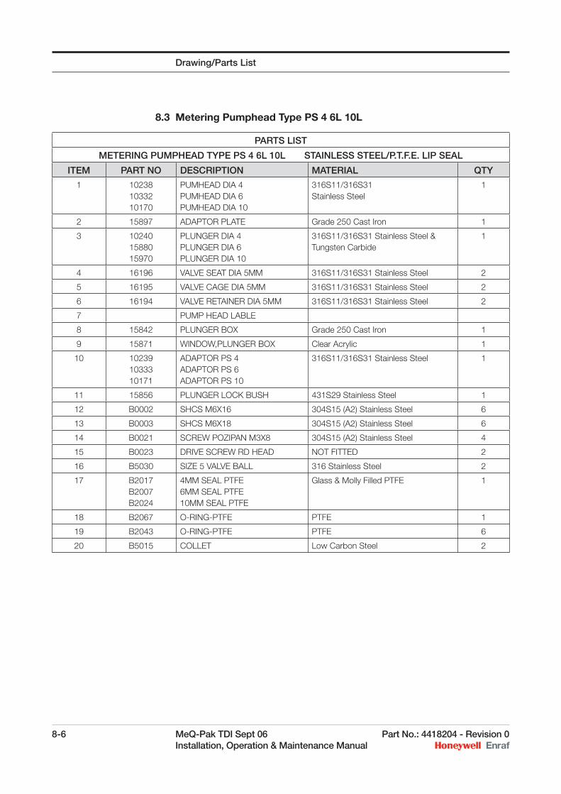
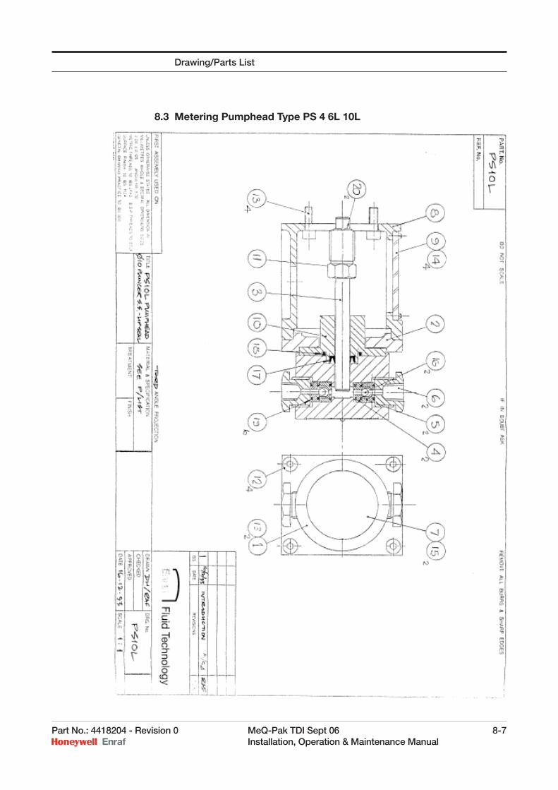
8.3 Metering Pumphead Type PS 4 6L 10L
PARTS LIST
METERING PUMPHEAD TYPE PS 4 6L 10L STAINLESS STEEL/P.T.F.E. LIP SEAL
ITEM PART NO DESCRIPTION MATERIAL QTY
1 10238 10332 10170
PUMHEAD DIA 4 PUMHEAD DIA 6 PUMHEAD DIA 10
316S11/316S31 Stainless Steel
1
2 15897 ADAPTOR PLATE Grade 250 Cast Iron 1
3 10240 15880 15970
PLUNGER DIA 4 PLUNGER DIA 6 PLUNGER DIA 10
316S11/316S31 Stainless Steel & Tungsten Carbide
1
4 16196 VALVE SEAT DIA 5MM 316S11/316S31 Stainless Steel 2
5 16195 VALVE CAGE DIA 5MM 316S11/316S31 Stainless Steel 2
6 16194 VALVE RETAINER DIA 5MM 316S11/316S31 Stainless Steel 2
7 PUMP HEAD LABLE
8 15842 PLUNGER BOX Grade 250 Cast Iron 1
9 15871 WINDOW,PLUNGER BOX Clear Acrylic 1
10 10239 10333 10171
ADAPTOR PS 4 ADAPTOR PS 6 ADAPTOR PS 10
316S11/316S31 Stainless Steel 1
11 15856 PLUNGER LOCK BUSH 431S29 Stainless Steel 1
12 B0002 SHCS M6X16 304S15 (A2) Stainless Steel 6
13 B0003 SHCS M6X18 304S15 (A2) Stainless Steel 6
14 B0021 SCREW POZIPAN M3X8 304S15 (A2) Stainless Steel 4
15 B0023 DRIVE SCREW RD HEAD NOT FITTED 2
16 B5030 SIZE 5 VALVE BALL 316 Stainless Steel 2
17 B2017 B2007 B2024
4MM SEAL PTFE 6MM SEAL PTFE 10MM SEAL PTFE
Glass & Molly Filled PTFE 1
18 B2067 O-RING-PTFE PTFE 1
19 B2043 O-RING-PTFE PTFE 6
20 B5015 COLLET Low Carbon Steel 2
Drawing/Parts List
Part No.: 4418204 - Revision 0 MeQ-Pak TDI Sept 06 8-7 Installation, Operation & Maintenance Manual
8.3 Metering Pumphead Type PS 4 6L 10L
Drawing/Parts List
8-8 MeQ-Pak TDI Sept 06 Part No.: 4418204 - Revision 0 Installation, Operation & Maintenance Manual
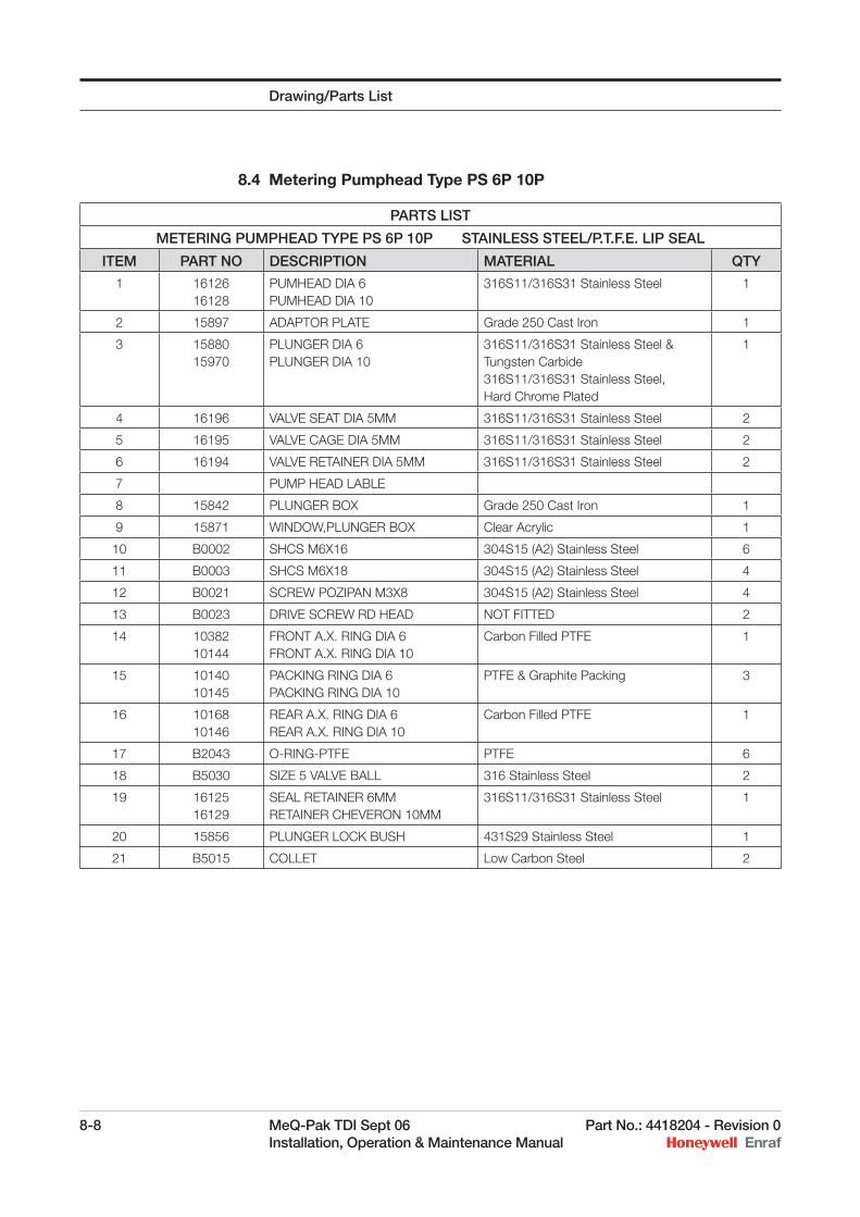
8.4 Metering Pumphead Type PS 6P 10P
PARTS LIST
METERING PUMPHEAD TYPE PS 6P 10P STAINLESS STEEL/P.T.F.E. LIP SEAL
ITEM PART NO DESCRIPTION MATERIAL QTY
1 16126 16128
PUMHEAD DIA 6 PUMHEAD DIA 10
316S11/316S31 Stainless Steel 1
2 15897 ADAPTOR PLATE Grade 250 Cast Iron 1
3 15880 15970
PLUNGER DIA 6PLUNGER DIA 10
316S11/316S31 Stainless Steel & Tungsten Carbide316S11/316S31 Stainless Steel, Hard Chrome Plated
1
4 16196 VALVE SEAT DIA 5MM 316S11/316S31 Stainless Steel 2
5 16195 VALVE CAGE DIA 5MM 316S11/316S31 Stainless Steel 2
6 16194 VALVE RETAINER DIA 5MM 316S11/316S31 Stainless Steel 2
7 PUMP HEAD LABLE
8 15842 PLUNGER BOX Grade 250 Cast Iron 1
9 15871 WINDOW,PLUNGER BOX Clear Acrylic 1
10 B0002 SHCS M6X16 304S15 (A2) Stainless Steel 6
11 B0003 SHCS M6X18 304S15 (A2) Stainless Steel 4
12 B0021 SCREW POZIPAN M3X8 304S15 (A2) Stainless Steel 4
13 B0023 DRIVE SCREW RD HEAD NOT FITTED 2
14 1038210144
FRONT A.X. RING DIA 6FRONT A.X. RING DIA 10
Carbon Filled PTFE 1
15 10140 10145
PACKING RING DIA 6 PACKING RING DIA 10
PTFE & Graphite Packing 3
16 10168 10146
REAR A.X. RING DIA 6 REAR A.X. RING DIA 10
Carbon Filled PTFE 1
17 B2043 O-RING-PTFE PTFE 6
18 B5030 SIZE 5 VALVE BALL 316 Stainless Steel 2
19 16125 16129
SEAL RETAINER 6MM RETAINER CHEVERON 10MM
316S11/316S31 Stainless Steel 1
20 15856 PLUNGER LOCK BUSH 431S29 Stainless Steel 1
21 B5015 COLLET Low Carbon Steel 2
Drawing/Parts List
Part No.: 4418204 - Revision 0 MeQ-Pak TDI Sept 06 8-9 Installation, Operation & Maintenance Manual
8.4 Metering Pumphead Type PS 6P 10P
Drawing/Parts List
8-10 MeQ-Pak TDI Sept 06 Part No.: 4418204 - Revision 0 Installation, Operation & Maintenance Manual
8.5 Metering Pumphead Type PS15/20/30/40/50
PARTS LIST
METERING PUMPHEAD TYPE PS15/20/30/40/50 STAINLESS STEEL/P.T.F.E. LIP SEAL
ITEM PART NO DESCRIPTION MATERIAL QTY1 10204
10036 10241 10027 10026
PUMHEAD DIA 15 PUMHEAD DIA 20 PUMHEAD DIA 30 PUMHEAD DIA 40 PUMHEAD DIA 50
316S11/316S31 Stainless Steel 1 1 1 1 1
2 10205 10037 10242 10029 10028
ADAPTOR PLUNGER 15 ADAPTOR PLUNGER 20 ADAPTOR PLUNGER 30 ADAPTOR PLUNGER 40 ADAPTOR PLUNGER 50
316S11/316S31 Stainless Steel 1 1 1 1 1
3 10206 15977 10243 15886 15889
PLUNGER DIA 15 PLUNGER DIA 20 PLUNGER DIA 30 PLUNGER DIA 40 PLUNGER DIA 50
316S11/316S31 Stainless Steel Hard Chrome Plated
1 1 1 1 1
4 10032 10008
VALVE SEAT 12MM-15/20 VALVE SEAT 22MM-30/40/50
316S11/316S31 Stainless Steel 2 2
5 10033 10009
VALVE CAGE 12MM-15/20 VALVE CAGE 22MM-30/40/50
316S11/316S31 Stainless Steel 2 2
6 10034 10010
CONNECTOR 12MM-15/20 CONNECTOR 22MM-30/40/50
316S11/316S31 Stainless Steel 2 2
7 10011 VALVE BRIDGE 22MM 316S11/316S31 or Cast ANC 3A Stainless Steel
2
8 PUMPHEAD LABEL 1
9 15842 PLUNGER BOX Grade 250 Cast Iron 1
10 15871 WINDOW, PLUNGER BOX Clear Acrylic 1
11 B0002 SHCS M6X16 304S15 (A2) Stainless Steel 4
12 B0003 SHCS M6X18 304S15 (A2) Stainless Steel 4
13 B0009 B0008 B0012
SHCS M6X40-15/20 SHCS M6X50-30 SHCS M6X53 S.ST-40/50
304S15 (A2) Stainless Steel 8 8 8
14 B0021 SCREW POZIPAN M3X8 304S15 (A2) Stainless Steel 4
15 B0023 B2023
DRIVE SCREW RD HEAD-15/20 DRIVE SCREW RD HEAD-30/40/50
NOT FITTED 2 2
16 B2016 B2019 B2031 B2030 B2032
15MM SEAL PTFE 20MM SEAL PTFE 30MM SEAL PTFE 40MM SEAL PTFE 50MM SEAL PTFE
Glass & Molly Filled PTFE 1 1 1 1 1
17 B2044 B2045
O-RING-PTFE 15/20 O-RING-PTFE 30/40/50
PTFE 6 6
18 B5033 B5032
SIZE 12 VALVE BALL 15/20 SIZE 22 VALVE BALL 30/40/50
316S31 Stainless Steel 2 2
19 15856 PLUNGER LOCK BUSH 431S29 Stainless Steel 1
20 B5015 COLLET Low Carbon Steel 2
Drawing/Parts List
Part No.: 4418204 - Revision 0 MeQ-Pak TDI Sept 06 8-11 Installation, Operation & Maintenance Manual
8.5 Metering Pumphead Type PS15/20/30/40/50
Drawing/Parts List
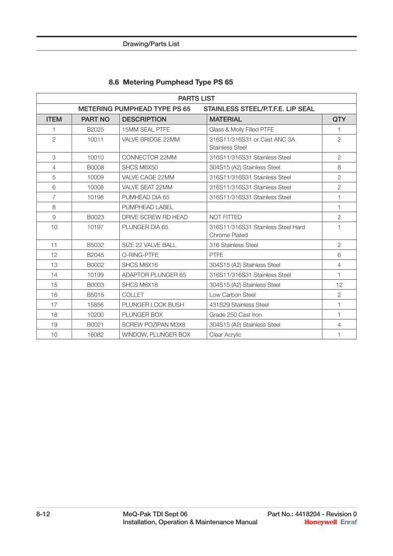
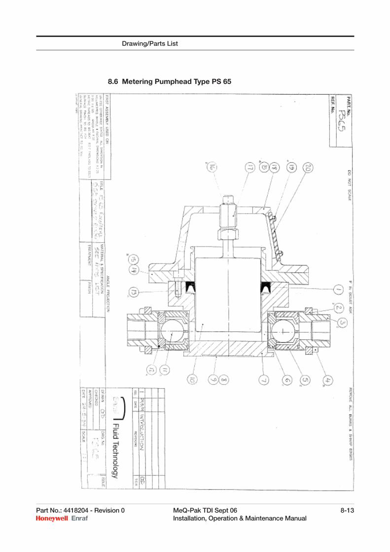
8.6 Metering Pumphead Type PS 65
PARTS LIST
METERING PUMPHEAD TYPE PS 65 STAINLESS STEEL/P.T.F.E. LIP SEAL
ITEM PART NO DESCRIPTION MATERIAL QTY
1 B2025 15MM SEAL PTFE Glass & Molly Filled PTFE 1
2 10011 VALVE BRIDGE 22MM 316S11/316S31 or Cast ANC 3A Stainless Steel
2
3 10010 CONNECTOR 22MM 316S11/316S31 Stainless Steel 2
4 B0008 SHCS M6X50 304S15 (A2) Stainless Steel 8
5 10009 VALVE CAGE 22MM 316S11/316S31 Stainless Steel 2
6 10008 VALVE SEAT 22MM 316S11/316S31 Stainless Steel 2
7 10198 PUMHEAD DIA 65 316S11/316S31 Stainless Steel 1
8 PUMPHEAD LABEL 1
9 B0023 DRIVE SCREW RD HEAD NOT FITTED 2
10 10197 PLUNGER DIA 65 316S11/316S31 Stainless Steel Hard Chrome Plated
1
11 B5032 SIZE 22 VALVE BALL 316 Stainless Steel 2
12 B2045 O-RING-PTFE PTFE 6
13 B0002 SHCS M6X16 304S15 (A2) Stainless Steel 4
14 10199 ADAPTOR PLUNGER 65 316S11/316S31 Stainless Steel 1
15 B0003 SHCS M6X18 304S15 (A2) Stainless Steel 12
16 B5015 COLLET Low Carbon Steel 2
17 15856 PLUNGER LOCK BUSH 431S29 Stainless Steel 1
18 10200 PLUNGER BOX Grade 250 Cast Iron 1
19 B0021 SCREW POZIPAN M3X8 304S15 (A2) Stainless Steel 4
10 16082 WINDOW, PLUNGER BOX Clear Acrylic 1
Drawing/Parts List
8-12 MeQ-Pak TDI Sept 06 Part No.: 4418204 - Revision 0 Installation, Operation & Maintenance Manual
Part No.: 4418204 - Revision 0 MeQ-Pak TDI Sept 06 8-13 Installation, Operation & Maintenance Manual
8.6 Metering Pumphead Type PS 65
Drawing/Parts List

Honeywell Enraf
6 Pennant Park
Standard Way
Fareham, UK PO16 8XU
United Kingdom
Tel: +44 1329 825 823
www.honeywell.com/ps
4418204_ENGFebruary 2009© 2009 Honeywell International Inc.