installation, operation & maintenance manual · pdf filerev. 09/21/16 installation,...
TRANSCRIPT
Rev. 09/21/16
Installation, Operation & Maintenance Manual
Two Post Surface Mounted Lift
MODEL 15000 15,000 LB CAPACITY - 3750 LB PER ARM
MODEL 18000 18,000 LB CAPACITY – 4500 LB PER ARM
200 Cabel Street, P.O. Box 3944 Louisville, Kentucky 40201-3944 Email:[email protected] Web site:www.challengerlifts.com
Office 800-648-5438 / 502-625-0700 Fax 502-587-1933
IMPORTANT: READ THIS MANUAL COMPLETELY BEFORE INSTALLING or OPERATING LIFT
Model 15000-18000 Installation, Operation and Maintenance
Page 2 Rev. 09/21/16 15-18000-IOM-A.doc
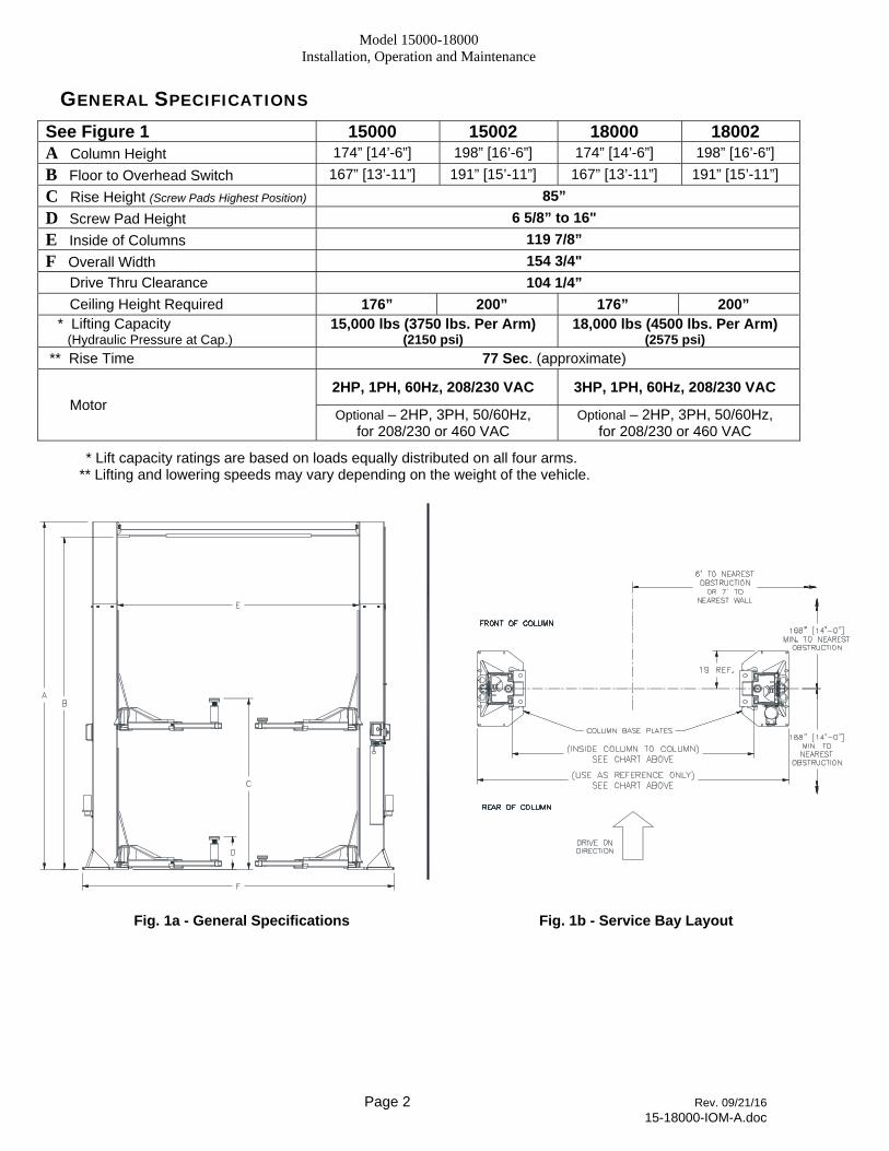
GENERAL SPECIFICATIONS
See Figure 1 15000 15002 18000 18002 A Column Height 174” [14’-6”] 198” [16’-6”] 174” [14’-6”] 198” [16’-6”]
B Floor to Overhead Switch 167” [13’-11”] 191” [15’-11”] 167” [13’-11”] 191” [15’-11”]
C Rise Height (Screw Pads Highest Position) 85”
D Screw Pad Height 6 5/8” to 16"
E Inside of Columns 119 7/8”
F Overall Width 154 3/4"
Drive Thru Clearance 104 1/4”
Ceiling Height Required 176” 200” 176” 200” * Lifting Capacity (Hydraulic Pressure at Cap.)
15,000 lbs (3750 lbs. Per Arm) (2150 psi)
18,000 lbs (4500 lbs. Per Arm) (2575 psi)
** Rise Time 77 Sec. (approximate)
Motor 2HP, 1PH, 60Hz, 208/230 VAC 3HP, 1PH, 60Hz, 208/230 VAC
Optional – 2HP, 3PH, 50/60Hz, for 208/230 or 460 VAC
Optional – 2HP, 3PH, 50/60Hz, for 208/230 or 460 VAC
* Lift capacity ratings are based on loads equally distributed on all four arms. ** Lifting and lowering speeds may vary depending on the weight of the vehicle.
Fig. 1a - General Specifications Fig. 1b - Service Bay Layout
Model 15000-18000 Installation, Operation and Maintenance
Page 3 Rev. 09/21/16 15-18000-IOM-A.doc
WARNING
VERTICAL CLEARANCE Check the height of the area where the lift is to be installed. Clearance should be calculated based on the full raised height of the lift.
Failure by purchaser to provide adequate clearance could result in unsatisfactory
lift performance, property damage, or personal injury.
FLOORING Be certain you have the proper concrete floor to properly handle the loaded lift. Floor should be in generally good condition with no large cracks, spalling or deterioration.
Minimum requirements for concrete are 4 inches minimum depth, with steel reinforcement, 3500 psi, cured for 28 days per local commercial practice. Floor should be level within 3/8 inch over the installation area. No anchors should be installed within 8 inches of any crack, edge, or expansion joint. If these conditions cannot be met, a pad may be poured to accommodate the lift.
Check with local building inspectors and/or permits office for any special instructions or approvals required for your installation.
A qualified person should be consulted to address seismic loads and other local or state requirements.
Failure by purchaser to provide the recommended mounting surface could result
in unsatisfactory lift performance, property damage, or personal injury.
LOCATION This lift has been evaluated for indoor use only with an operating ambient temp. range of 5 – 40°C (41– 104°F)
ELECTRICAL REQUIREMENTS For lift installation and operation it is necessary to have a dedicated circuit with circuit breaker or time delay fuse. Refer to wiring diagram for circuit sizing.
AIR REQUIREMENTS This lift is equipped with an air operated lock release system. The air supplied to the lift must be clean, dry, lubricated, and regulated to 90-120 psi, FRL (Filter/Regulator/Lubricator). The FRL must be within 30 feet of lift. Failure to provide clean, dry, lubricated, and pressure regulated air will void warranty on pneumatic components.
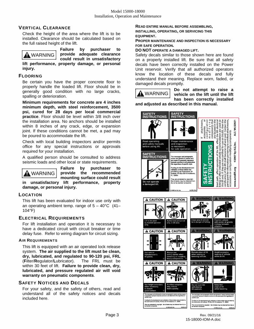
SAFETY NOTICES AND DECALS For your safety, and the safety of others, read and understand all of the safety notices and decals included here.
READ ENTIRE MANUAL BEFORE ASSEMBLING, INSTALLING, OPERATING, OR SERVICING THIS
EQUIPMENT. PROPER MAINTENANCE AND INSPECTION IS NECESSARY
FOR SAFE OPERATION. DO NOT OPERATE A DAMAGED LIFT. Safety decals similar to those shown here are found on a properly installed lift. Be sure that all safety decals have been correctly installed on the Power Unit reservoir. Verify that all authorized operators know the location of these decals and fully understand their meaning. Replace worn, faded, or damaged decals promptly.
Do not attempt to raise a vehicle on the lift until the lift has been correctly installed
and adjusted as described in this manual.
WARNING
WARNING

Model 15000-18000 Installation, Operation and Maintenance
Page 4 Rev. 09/21/16 15-18000-IOM-A.doc
RECEIVING The shipment should be thoroughly inspected as soon as it is received. The signed bill of lading is acknowledgement by the carrier of receipt in good condition of shipment covered by our invoice.
If any of the goods called for on this bill of lading are shorted or damaged, do not accept them until the carrier makes a notation on the freight bill of the shorted or damaged goods. Do this for your own protection.
NOTIFY Challenger Lifts AT ONCE if any hidden loss or damage is discovered after receipt.
IT IS DIFFICULT TO COLLECT FOR LOSS OR DAMAGE AFTER YOU HAVE GIVEN THE CARRIER A CLEAR RECEIPT.
File your claim with Challenger Lifts promptly. Support your claim with copies of the bill of lading, freight bill, and photographs, if available.
Component Packing List
PART # QTY/ LIFT
DESCRIPTION 15000 18000
12001 12001-18 1 POWER COLUMN ASS’Y
12002 12002-18 1 IDLER COLUMN ASS’Y
12004 1 OVERHEAD PACK
15-18000-HW-A 1 HARDWARE BOX
B12048S-1 4 ARM ASSEMBLY
12102 2
COLUMN EXT. (14’-6” O.A. HT.) 12022 COLUMN EXT. (16’-6” O.A. HT.) 12074 1 OVERHEAD SHUTOFF BAR ASS’Y 12045 1 OVERHEAD LIMIT SWITCH 12100
2 SYNC. CABLE ASS’Y (14’-6”)
12019 SYNC. CABLE ASS’Y (16’-6”) B12069 4 ADAPTER EXTENSION (4”) B12068 2 ADAPTER EXTENSION (8”) 12071 2 ADAPTER RACK 12093 4 ARM RESTRAINT ASSEMBLY
12119 12087-19 1
POWER UNIT – SINGLE PHASE 12089 12089-19 POWER UNIT – THREE PHASE
15-18000-LP-A 1 LITERATURE PACK
INSTALLATION IMPORTANT: Always wear safety glasses while installing lift.
TOOLS (MINIMUM REQUIRED) a. Tape measure, 16ft b. Chalk line c. 4ft level d. 10” adjustable wrench e. Standard open end wrenches 7/16”, 1/2", (2) 9/16”, (2) 11/16”, 3/4"
f. 5/16” allen wrench g. Needle nose pliers h. Hammer drill with 3/4” diameter carbide tipped
bits i. 2 lb hammer j. Torque wrench: 150 foot pounds minimum with 1
1/8” socket k. 12 ft. Step ladderl. Anti-Seize lubricant (for arm pins and foot pad
screw threads and stop rings)
LAYOUT 1) Layout the service bay according to the
architect’s plans or owners instructions (see Fig. 1b). Failure to install in this orientation can result in personal and property damage. Be certain that the proper conditions exist, see page 3.
2) Assemble column extension to column using 3/8”-16 x 3/4" lg Hex flange head bolt. Repeat for opposite column and extension.
3) Erect and align both column assemblies.
LOCK RELEASE/PAWL
Fig. 2 – Locking Pawl Assembly
4) Install the locking pawl, actuator, and spring (Fig. 2). Adjust air cylinder clevis to retract lock against inside of back of column when air cylinder is fully extended. Tighten air cylinder clevis jam nut against clevis.
Model 15000-18000 Installation, Operation and Maintenance
Page 5 Rev. 09/21/16 15-18000-IOM-A.doc
ANCHORING 5) The anchor bolts must be installed at least 8”
from any crack, edge, or expansion joint.
6) Use a concrete hammer drill with a 3/4 inch carbide bit. Tip diameter should conform to ANSI Standard B94.12-1977 (.775 to .787). Do not use excessively worn bits or bits which have been incorrectly sharpened. A core bit may be necessary if an obstruction is encountered. Never substitute with shorter anchor.
7) Recheck “Inside of Columns” dimension (Fig. 1). Drill the anchor holes using the base plate as a template. Drill through the floor if possible or to a depth of 5 inches minimum.
Complete steps 8 thru 11 for the six (6) exposed anchors around each column, then raise the carriages. Repeat steps 8 thru 11 for the two (2) anchors under each carriage.
8) Vacuum dust from the hole for proper holding power.
9) Shim both columns to plumb using the shims provided as shown in Fig. 3. DO NOT shim more than 1/2" at any given point. Use a level no less than 24” in length to plumb columns.
10) Assemble washer and nut to anchor with nut just below impact section of bolt. Drive anchor into hole until nut and washer contact base.
Fig. 3 – Column Shimming
11) Tighten power column anchors and recheck column for plumb. Re-shim if necessary. Torque to 150 foot pounds to set anchors.
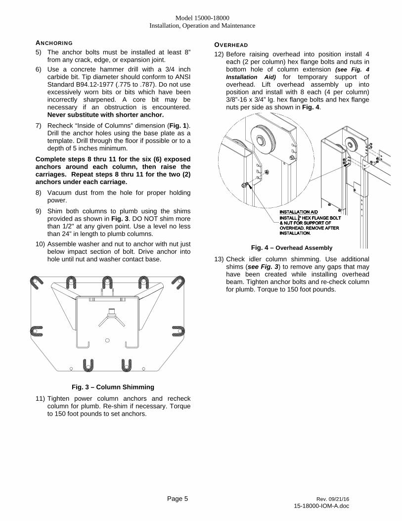
OVERHEAD 12) Before raising overhead into position install 4
each (2 per column) hex flange bolts and nuts in bottom hole of column extension (see Fig. 4 Installation Aid) for temporary support of overhead. Lift overhead assembly up into position and install with 8 each (4 per column) 3/8”-16 x 3/4” lg. hex flange bolts and hex flange nuts per side as shown in Fig. 4.
Fig. 4 – Overhead Assembly
13) Check idler column shimming. Use additional shims (see Fig. 3) to remove any gaps that may have been created while installing overhead beam. Tighten anchor bolts and re-check column for plumb. Torque to 150 foot pounds.
Model 15000-18000 Installation, Operation and Maintenance
Page 6 Rev. 09/21/16 15-18000-IOM-A.doc
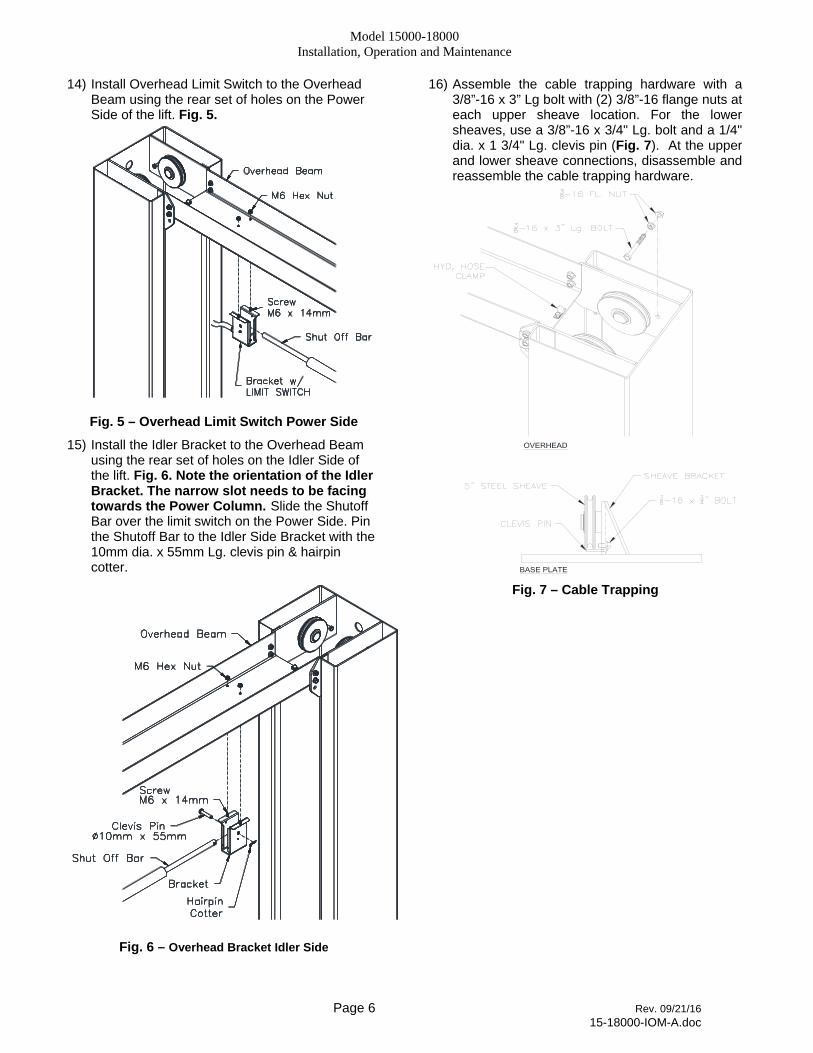
14) Install Overhead Limit Switch to the Overhead Beam using the rear set of holes on the Power Side of the lift. Fig. 5.
Fig. 5 – Overhead Limit Switch Power Side
15) Install the Idler Bracket to the Overhead Beam using the rear set of holes on the Idler Side of the lift. Fig. 6. Note the orientation of the Idler Bracket. The narrow slot needs to be facing towards the Power Column. Slide the Shutoff Bar over the limit switch on the Power Side. Pin the Shutoff Bar to the Idler Side Bracket with the 10mm dia. x 55mm Lg. clevis pin & hairpin cotter.
Fig. 6 – Overhead Bracket Idler Side
16) Assemble the cable trapping hardware with a 3/8”-16 x 3” Lg bolt with (2) 3/8”-16 flange nuts at each upper sheave location. For the lower sheaves, use a 3/8”-16 x 3/4" Lg. bolt and a 1/4" dia. x 1 3/4" Lg. clevis pin (Fig. 7). At the upper and lower sheave connections, disassemble and reassemble the cable trapping hardware.
Fig. 7 – Cable Trapping
Model 15000-18000 Installation, Operation and Maintenance
Page 7 Rev. 09/21/16 15-18000-IOM-A.doc
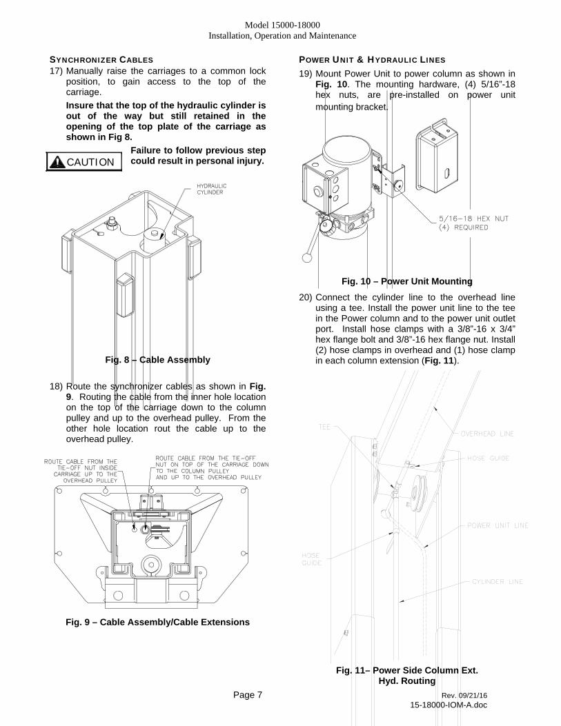
SYNCHRONIZER CABLES 17) Manually raise the carriages to a common lock
position, to gain access to the top of the carriage.
Insure that the top of the hydraulic cylinder is out of the way but still retained in the opening of the top plate of the carriage as shown in Fig 8.
Failure to follow previous step could result in personal injury.
Fig. 8 – Cable Assembly
18) Route the synchronizer cables as shown in Fig. 9. Routing the cable from the inner hole location on the top of the carriage down to the column pulley and up to the overhead pulley. From the other hole location rout the cable up to the overhead pulley.
Fig. 9 – Cable Assembly/Cable Extensions
POWER UNIT & HYDRAULIC LINES 19) Mount Power Unit to power column as shown in
Fig. 10. The mounting hardware, (4) 5/16”-18 hex nuts, are pre-installed on power unit mounting bracket.
Fig. 10 – Power Unit Mounting
20) Connect the cylinder line to the overhead line using a tee. Install the power unit line to the tee in the Power column and to the power unit outlet port. Install hose clamps with a 3/8”-16 x 3/4” hex flange bolt and 3/8”-16 hex flange nut. Install (2) hose clamps in overhead and (1) hose clamp in each column extension (Fig. 11).
Fig. 11– Power Side Column Ext.
Hyd. Routing
C A U T I O N
Model 15000-18000 Installation, Operation and Maintenance
Page 8 Rev. 09/21/16 15-18000-IOM-A.doc
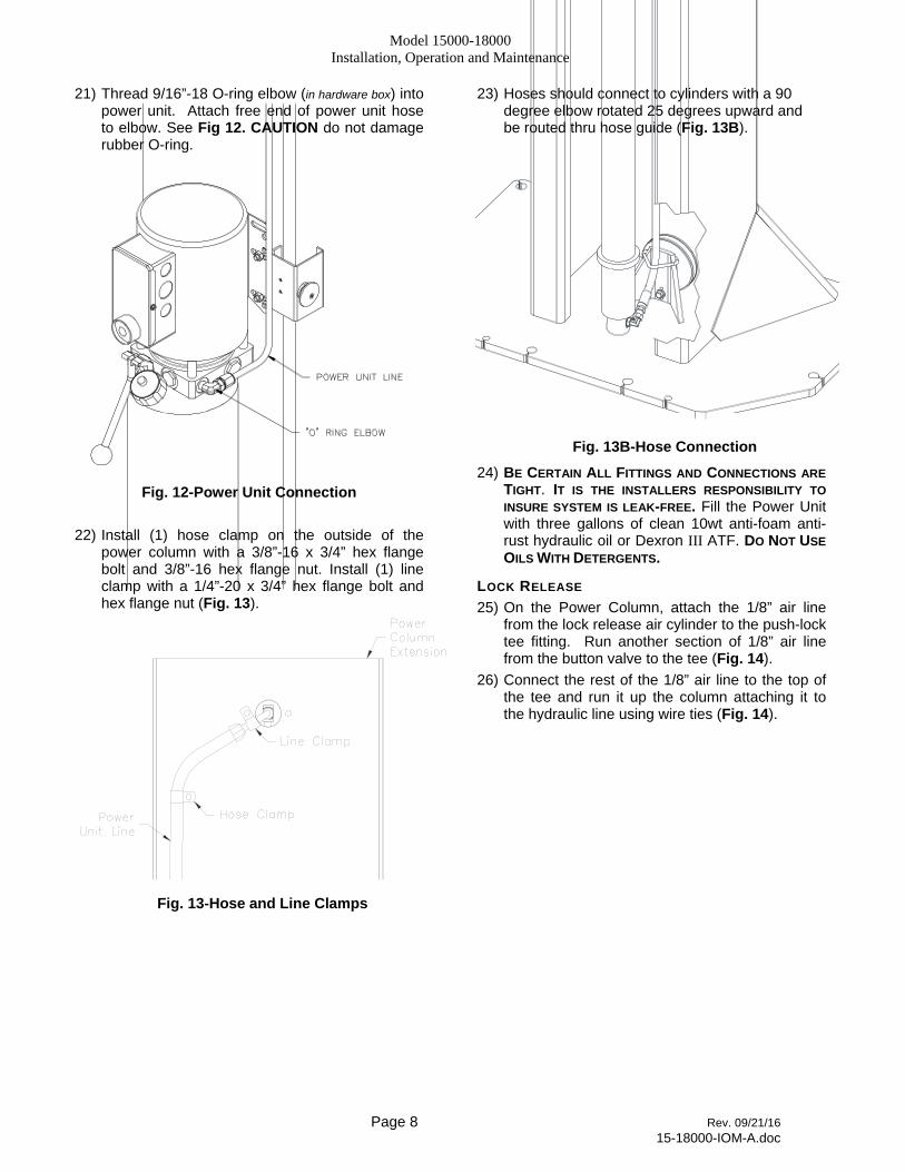
21) Thread 9/16”-18 O-ring elbow (in hardware box) into power unit. Attach free end of power unit hose to elbow. See Fig 12. CAUTION do not damage rubber O-ring.
Fig. 12-Power Unit Connection
22) Install (1) hose clamp on the outside of the power column with a 3/8”-16 x 3/4” hex flange bolt and 3/8”-16 hex flange nut. Install (1) line clamp with a 1/4”-20 x 3/4” hex flange bolt and hex flange nut (Fig. 13).
Fig. 13-Hose and Line Clamps
23) Hoses should connect to cylinders with a 90 degree elbow rotated 25 degrees upward and be routed thru hose guide (Fig. 13B).
Fig. 13B-Hose Connection
24) BE CERTAIN ALL FITTINGS AND CONNECTIONS ARE
TIGHT. IT IS THE INSTALLERS RESPONSIBILITY TO
INSURE SYSTEM IS LEAK-FREE. Fill the Power Unit with three gallons of clean 10wt anti-foam anti-rust hydraulic oil or Dexron III ATF. DO NOT USE
OILS WITH DETERGENTS.
LOCK RELEASE 25) On the Power Column, attach the 1/8” air line
from the lock release air cylinder to the push-lock tee fitting. Run another section of 1/8” air line from the button valve to the tee (Fig. 14).
26) Connect the rest of the 1/8” air line to the top of the tee and run it up the column attaching it to the hydraulic line using wire ties (Fig. 14).

Model 15000-18000 Installation, Operation and Maintenance
Page 9 Rev. 09/21/16 15-18000-IOM-A.doc
Fig. 14-Lock Release
27) After running the 1/8” air line along the hydraulic line in the overhead and out the other opening in the Idler Column (Fig. 14), run the air line down the column using adhesive tab and wire ties. Attach it to the lock release air cylinder (Fig. 14).
ARM INSTALLATION 28) Lubricate the arm pin or carriage arm pin hole
with “anti-seize” and install the arms. Insure that the arm restraint gears engage and disengage properly. Arm restraints should disengage when lift is fully lowered (Fig. 15).
29) Extend the footpad to both extents and apply “anti-seize” to the retaining ring.
Fig. 15-Arm Installation
ADAPTER RACK INSTALLATION 30) Locate the two pre-drilled holes on the back of
each column 19” up from the top of the base plate and tap 5/16”-18. Center the adapter rack and attach with 3/8”-16 x 3/4" Lg hex flange cap screw and 3/8”-16 hex flange nut (Fig. 16).
Fig. 16-Adapter Rack Installation
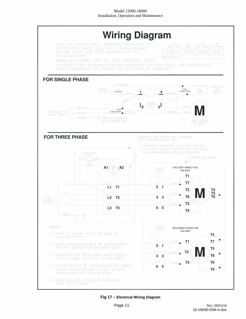
ELECTRICAL See Figure 17 for the following steps. 31) Wire tie Limit Switch cord to column hydraulic
line and power unit line. 32) Connect the Overhead Limit Switch Cord to
Power Unit as shown in Fig. 17. 33) Connect Power Unit to suitable electrical source
as shown in Fig. 17. 34) IMPORTANT: AFTER WIRING HAS BEEN
COMPLETED, TEST OPERATION OF POWER UNIT &
OVERHEAD LIMIT SWITCH. WHILE RAISING LIFT, OPERATE OVERHEAD SHUTOFF BAR. POWER UNIT
MOTOR SHOULD STOP WHEN SHUTOFF BAR IS
RAISED.
FINAL ADJUSTMENTS HYDRAULICS 35) Lower the lift to the floor and raise the lift
approximately one foot.
36) Start with Idler side first. Slowly and carefully loosen the bleed plug on top of the cylinder just enough to allow the entrapped air to escape. Repeat for power side.
37) Raise lift 6 inches. Repeat step 36 until no air comes out of cylinder.
38) Pressure test hydraulic system. Energize power unit, raise lift to full rise and continue to run motor for additional 10 seconds. (NOTE: pressure relief will make a high pitch squeal
Model 15000-18000 Installation, Operation and Maintenance
Page 10 Rev. 09/21/16 15-18000-IOM-A.doc
sound for these 10 seconds.) Check hydraulic system for leaks.
39) Energize power unit again for 10 seconds. With a clean rag, wipe down both cylinder rods. (The cylinders are shipped with a small amount of clear anti-corosive lubricant that will be forced out through the wiper when the lift reaches full rise.) If lubricant is not wiped clean from the cylinder rod, the cylinder will apear to be leaking.
SYNCHRONIZING CABLES
40) Raise lift and insure carriages lower into same lock position.
41) Adjust synchronizing cables so the tension is equal in both cables and carriages are firmly sitting on locks.
42) Cycle lift to insure that latches operate simultaneously. Adjust if necessary.
OWNER/OPERATOR CHECKLIST 43) Demonstrate the operation of the lift to the
owner/operator and review correct and safe lifting procedures using the Lifting It Right booklet as a guide.
44) Complete the Installation Checklist/Warranty Validation questionnaire with the owner. Review the terms of the warranty registration card, and return the card and a copy of the questionnaires to:
Challenger Lifts, Inc. 200 Cabel Street
Louisville, KY. 40206
Model 15000-18000 Installation, Operation and Maintenance
Page 11 Rev. 09/21/16 15-18000-IOM-A.doc
1
5
4
6
(Normally Open)
MFIELDCONECTIONS
FIELDCONECTIONS
A2A1
T9
T5T4
T6MT8
T3
T7
T2
T1
12
34
56L3
L2
L1
T3
T2
T1
FACTORY WIRED FOR208−240V
6
4
2
5
3
1
RECONNECTIONS FOR440−480V
T3
T2
T1
T9
T6
T7
T4
T8
T5
FOR THREE PHASE
M
FOR SINGLE PHASE
Wiring Diagram
Fig 17 – Electrical Wiring Diagram
Model 15000-18000 Installation, Operation and Maintenance
Page 12 Rev. 09/21/16 15-18000-IOM-A.doc
OPERATION PROCEDURE
SAFETY NOTICES AND DECALS This product is furnished with graphic safety warning labels, which are reproduced on page 3 of these instructions. Do not remove or deface these warning labels, or allow them to be removed or defaced. For your safety, and the safety of others, read and understand all of the safety notices and decals included.
OWNER/EMPLOYER RESPONSIBILITIES
This lift has been designed and constructed according to ANSI/ALI ALCTV-2011 standard. The standard applies to lift manufactures, as well as to owners and employers. The owner/employer’s responsibilities as prescribed by ANSI/ALI ALOIM-2008, are summarized below. For exact wording refer to the actual standard provided with this manual in the literature pack.
The Owner/Employer shall insure that lift operators are qualified and that they are trained in the safe use and operation of the lift using the manufacturer’s operating instructions; ALI/SM 93 -1, ALI Lifting it Right safety manual; ALI/ST-90 ALI Safety Tips card; ANSI/ALI ALOIM-2008, American National Standard for Automotive Lifts-Safety Requirements for Operation, Inspection and Maintenance; ALI/WL Series, ALI Uniform Warning Label Decals/Placards; and in case of frame engaging lifts, ALI/LP-GUIDE, Vehicle Lifting Points/Quick Reference Guide for Frame Engaging Lifts.
The Owner/Employer shall establish procedures to periodically inspect the lift in accordance with the lift manufacturer’s instructions or ANSI/ALI ALOIM-2008, American National Standard for Automotive Lifts-Safety Requirements for Operation, Inspection and Maintenance; and the employer shall insure that the lift inspectors are qualified and that they are adequately trained in the inspection of the lift.
The Owner/Employer shall establish procedures to periodically maintain the lift in accordance with the lift manufacturer’s instructions or ANSI/ALIOIM-2008, American National Standard for Automotive Lifts-Safety Requirements for Operation, Inspection and Maintenance; and the employer shall insure that the lift maintenance personnel are qualified and that they are adequately trained in the maintenance of the lift.
The Owner/Employer shall maintain the periodic inspection and maintenance records recommended by the manufacturer or ANSI/ALI ALOIM-2008, American National Standard for Automotive Lifts-Safety Requirements for Operation, Inspection and Maintenance.
The Owner/Employer shall display the lift manufacturer’s operating instructions; ALI/SM 93 -1, ALI Lifting it Right safety manual; ALI/ST-90 ALI Safety Tips card; ANSI/ALI ALOIM-2008, American National Standard for Automotive Lifts-Safety Requirements for Operation, Inspection and
Maintenance; and in the case of frame engaging lift, ALI/LP-GUIDE, Vehicle Lifting Points/Quick Reference Guide for Frame Engaging Lifts; in a conspicuous location in the lift area convenient to the operator.
IMPORTANT SAFETY INSTRUCTIONS
When using your garage equipment, basic safety precautions should always be followed, including the following:
1. Read all instructions.
2. Care must be taken as burns can occur from touching hot parts.
3. To reduce the risk of fire, do not operate equipment in the vicinity of open containers of flammable liquids (gasoline).
4. Keep hair, loose clothing, fingers, and all parts of body away from moving parts.
5. Use only as described in this manual. Use only manufacturer’s recommended attachments.
6. ALWAYS WEAR SAFETY GLASSES. Everyday eyeglasses only have impact resistant lenses, they are not safety glasses.
SAVE THESE INSTRUCTIONS
Model 15000-18000 Installation, Operation and Maintenance
Page 13 Rev. 09/21/16 15-18000-IOM-A.doc
LIFTING A VEHICLE 1) Insure that the lifting arms are parked, out to full
drive thru position.
2) Center the vehicle between the columns in the service bay and position the vehicle’s center of gravity midpoint between the columns. NOTE: the center of gravity is based on the weight distribution and is not the same as the center point of the vehicle.
DO NOT EXCEED 3750 POUNDS PER ARM (15K).
DO NOT EXCEED 4500 POUNDS PER ARM (18K).
DO NOT ATTEMPT TO LIFT THE VEHICLE WITH ONLY TWO
ARMS, AS THIS WILL VOID THE WARRANTY
INSURE THAT THE HIGHEST POINT ON THE VEHICLE WILL
CONTACT THE OVERHEAD LIMIT SWITCH BAR.
DO NOT PLACE THE VEHICLE IN THE SERVICE BAY
BACKWARDS.
REFER TO THE VEHICLE MANUFACTURERS SERVICE
MANUAL, TECHNICAL BULLETINS, “VEHICLE LIFTING
POINTS GUIDE” (ALI/LP-GUIDE) OR OTHER
PUBLICATIONS TO LOCATE THE RECOMMENDED LIFTING
POINTS.
3) Position the arms and adapters so all four pads contact the vehicle simultaneously.
The vehicle should remain level during lifting.
4) Raise the lift until all four wheels are off the ground. Test the stability of the vehicle by attempting to rock the vehicle. Check adapters for secure contact with vehicle lift points. If the vehicle seems unstable, lower the lift and readjust the arms. If the vehicle is stable, raise the vehicle to a height a few inches above the desired working height.
5) Lower the vehicle until the safety latches on both columns engage. The vehicle should remain level when both latches are engaged. If one side engages and the other continues to descend, stop lowering the vehicle, raise it several inches, and try again to engage both latches.
Always lower lift into locks before entering the area beneath the vehicle. Always use safety stands when removing or installing heavy components.
LOWERING A VEHICLE 1) Insure that the area under the vehicle is clear of
personnel and tools.
2) Raise the vehicle until both locks are free.
3) Disengage the locks by pressing and holding the lock release palm button.
4) Lower the vehicle by depressing the lowering valve handle.
5) Continue to lower the vehicle until the carriages stop against the base plate. Retract the extension arms, and park them.
LOSS OF POWER If for any reason the lift will not raise off the locks or the locks will not retract, consult factory authorized personnel.
DO NOT OVERRIDE ANY SAFETY FEATURE IN AN ATTEMPT TO LOWER THE LIFT.
Model 15000-18000 Installation, Operation and Maintenance
Page 14 Rev. 09/21/16 15-18000-IOM-A.doc
MAINTENANCE To avoid personal injury, permit only qualified personnel to perform maintenance on this equipment. Maintenance personnel should follow lockout/tagout instructions per ANSI Z244.1.
The following maintenance points are suggested as the basis of a routine maintenance program. The actual maintenance program should be tailored to the installation. See ANSI/ALI ALOIM booklet for periodic inspection checklist and maintenance log sheet.
If lift stops short of full rise or chatters, check fluid level and bleed both cylinders per Installation Instructions.
Replace all Safety, Warning or Caution Labels if missing or damaged (See Installation instructions page 3.)
Daily Keep lift components clean.
Check for loose or broken parts.
Check hydraulic system for fluid leaks.
Check adapters for damage or excessive wear. Replace as required with genuine Challenger Lifts parts.
Check lock release activation. When properly adjusted, the idler column lock should rest firmly against the back of the column when engaged and against the spring mount tab when disengaged.
Weekly Check synchronizer cables and sheaves for wear.
Replace as required with genuine Challenger Lifts parts.
Check synchronizer cable tension per Installation Instructions. Adjust if necessary.
Monthly Torque concrete anchor bolts to 80 ft-lbs.
Visually inspect concrete floor for cracks and/or sprawls within 12” of base plate
Check overhead shutoff switch. While raising lift, operate overhead shutoff bar. Power Unit motor should stop when bar is raised.
Lubricate carriage slide tracks with heavy viscous grease. (Grease all (4) corners of both columns.)
If any problems are encountered, contact your local service representative.

Model 15000-18000 Installation, Operation and Maintenance
Page 15 Rev. 09/21/16 15-18000-IOM-A.doc
PARTS BREAKDOWN Fig A. Column Extension & Overhead
ITEM # PART # QTY/LIFT DESCRIPTION
1 12025
1 POWER COLUMN WELD
12026 IDLER COLUMN WELD
2 12102
2 COLUMN EXTENSION (14’-6” O.A. Ht.)
12022 COLUMN EXTENSION (16’-6” O.A. Ht.)
3 12039 1 OVERHEAD
4 A2067 1 SHUTOFF BAR
5 31129 1 SHUTOFF BAR CUSHION
6
B2064-01 1 LIMIT SWITCH PACKAGE
(INCLUDES SWITCH w/ CORD, BOTH BRACKETS, & ITEMS 7-10)
7 B2065-3 4 M6 x 14mm PHILLIPS PAN HEAD SCREW
8 B2065-4 4 M6 SERRATED FLANGE HEX NUT
9 B2065-5 1 CLEVIS PIN 10mm x 55 Lg.
10 GJY12-3 1 HAIRPIN COTTER
11 A1153 24 3/8”-16NC HEX. FLG. HD. C.S x 3/4” Lg.
12 A1154 32 3/8”-16NC HEX. FLG. NUT
13 A1122-12 4 HOSE CLAMP (.68”) FOR 3/8” HOSE
14 A2159 4 3/8”-16NC x 3” Lg. HEX HEAD CAP SCREW
12116H 1
COLUMN EXTENSION PACK (14’-6” O.A. Ht.) Items (2, 64, 65, 66, 67)
12117H COLUMN EXTENSION PACK (16’-6” O.A. Ht.) Items (2, 50, 64, 65, 66, 67)
Replace all worn, damaged, or broken parts with parts approved by Challenger Lifts Inc. or with parts meeting Challenger Lifts Inc. specifications.
Contact your local Challenger Lifts Parts Distributor for pricing and availability. (Call Challenger Lifts Inc. (502) 625-0700 for the Parts Distributor in your area)

Model 15000-18000 Installation, Operation and Maintenance
Page 16 Rev. 09/21/16 15-18000-IOM-A.doc
PARTS BREAKDOWN (continued)
Fig B. Lock-Power/Idler
Model 15000-18000 Installation, Operation and Maintenance
Page 17 Rev. 09/21/16 15-18000-IOM-A.doc
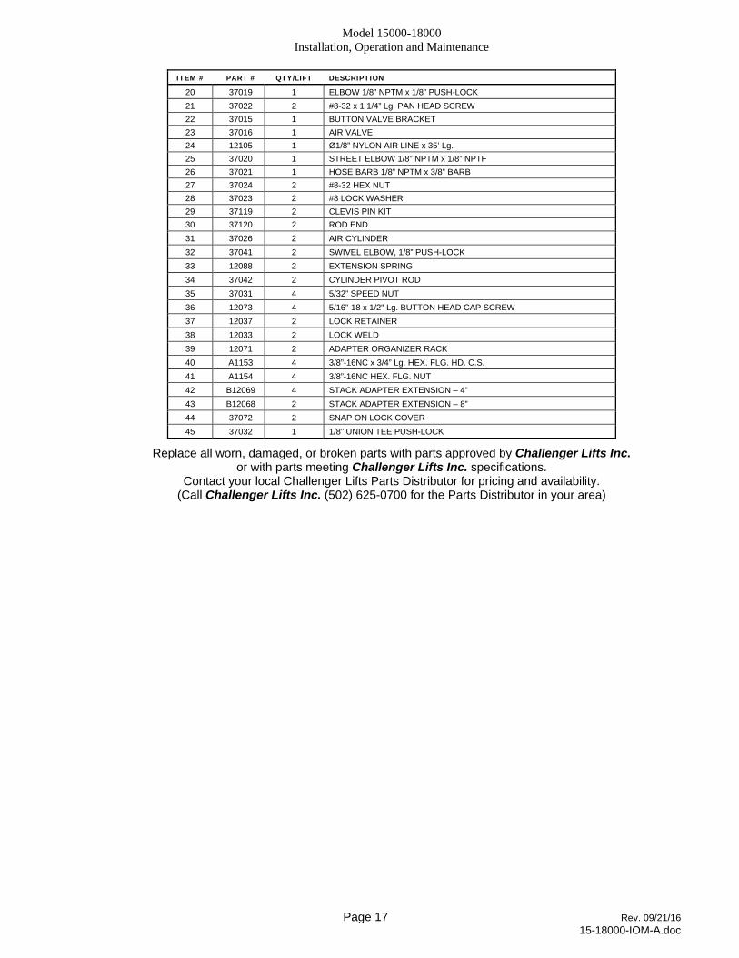
ITEM # PART # QTY/LIFT DESCRIPTION
20 37019 1 ELBOW 1/8” NPTM x 1/8” PUSH-LOCK
21 37022 2 #8-32 x 1 1/4” Lg. PAN HEAD SCREW
22 37015 1 BUTTON VALVE BRACKET
23 37016 1 AIR VALVE
24 12105 1 Ø1/8” NYLON AIR LINE x 35’ Lg.
25 37020 1 STREET ELBOW 1/8” NPTM x 1/8” NPTF
26 37021 1 HOSE BARB 1/8” NPTM x 3/8” BARB
27 37024 2 #8-32 HEX NUT
28 37023 2 #8 LOCK WASHER
29 37119 2 CLEVIS PIN KIT
30 37120 2 ROD END
31 37026 2 AIR CYLINDER
32 37041 2 SWIVEL ELBOW, 1/8” PUSH-LOCK
33 12088 2 EXTENSION SPRING
34 37042 2 CYLINDER PIVOT ROD
35 37031 4 5/32” SPEED NUT
36 12073 4 5/16”-18 x 1/2" Lg. BUTTON HEAD CAP SCREW
37 12037 2 LOCK RETAINER
38 12033 2 LOCK WELD
39 12071 2 ADAPTER ORGANIZER RACK
40 A1153 4 3/8”-16NC x 3/4” Lg. HEX. FLG. HD. C.S.
41 A1154 4 3/8”-16NC HEX. FLG. NUT
42 B12069 4 STACK ADAPTER EXTENSION – 4”
43 B12068 2 STACK ADAPTER EXTENSION – 8”
44 37072 2 SNAP ON LOCK COVER
45 37032 1 1/8” UNION TEE PUSH-LOCK
Replace all worn, damaged, or broken parts with parts approved by Challenger Lifts Inc. or with parts meeting Challenger Lifts Inc. specifications.
Contact your local Challenger Lifts Parts Distributor for pricing and availability. (Call Challenger Lifts Inc. (502) 625-0700 for the Parts Distributor in your area)
Model 15000-18000 Installation, Operation and Maintenance
Page 18 Rev. 09/21/16 15-18000-IOM-A.doc
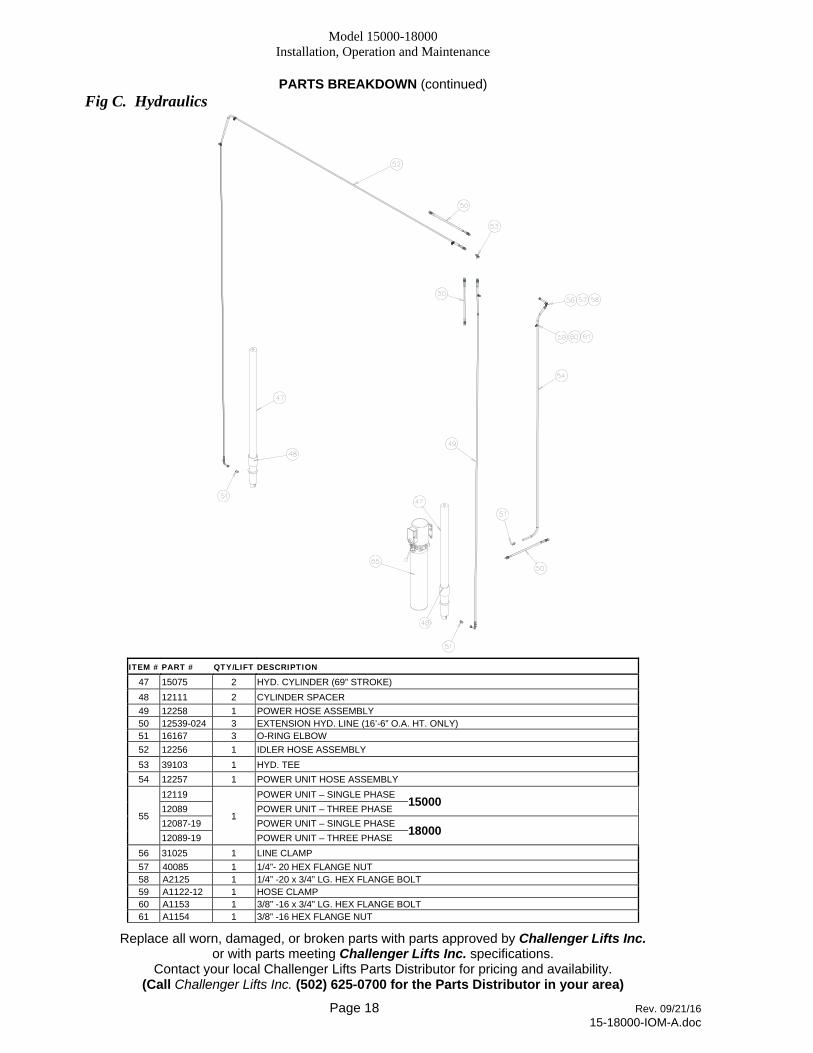
PARTS BREAKDOWN (continued) Fig C. Hydraulics
ITEM # PART # QTY/LIFT DESCRIPTION
47 15075 2 HYD. CYLINDER (69” STROKE)
48 12111 2 CYLINDER SPACER
49 12258 1 POWER HOSE ASSEMBLY 50 12539-024 3 EXTENSION HYD. LINE (16’-6” O.A. HT. ONLY) 51 16167 3 O-RING ELBOW
52 12256 1 IDLER HOSE ASSEMBLY
53 39103 1 HYD. TEE
54 12257 1 POWER UNIT HOSE ASSEMBLY
55
12119
1
POWER UNIT – SINGLE PHASE 15000 12089 POWER UNIT – THREE PHASE
12087-19 POWER UNIT – SINGLE PHASE 18000 12089-19 POWER UNIT – THREE PHASE
56 31025 1 LINE CLAMP
57 40085 1 1/4”- 20 HEX FLANGE NUT 58 A2125 1 1/4” -20 x 3/4” LG. HEX FLANGE BOLT 59 A1122-12 1 HOSE CLAMP 60 A1153 1 3/8” -16 x 3/4” LG. HEX FLANGE BOLT 61 A1154 1 3/8” -16 HEX FLANGE NUT
Replace all worn, damaged, or broken parts with parts approved by Challenger Lifts Inc. or with parts meeting Challenger Lifts Inc. specifications.
Contact your local Challenger Lifts Parts Distributor for pricing and availability. (Call Challenger Lifts Inc. (502) 625-0700 for the Parts Distributor in your area)
Model 15000-18000 Installation, Operation and Maintenance
Page 19 Rev. 09/21/16 15-18000-IOM-A.doc
PARTS BREAKDOWN (continued)
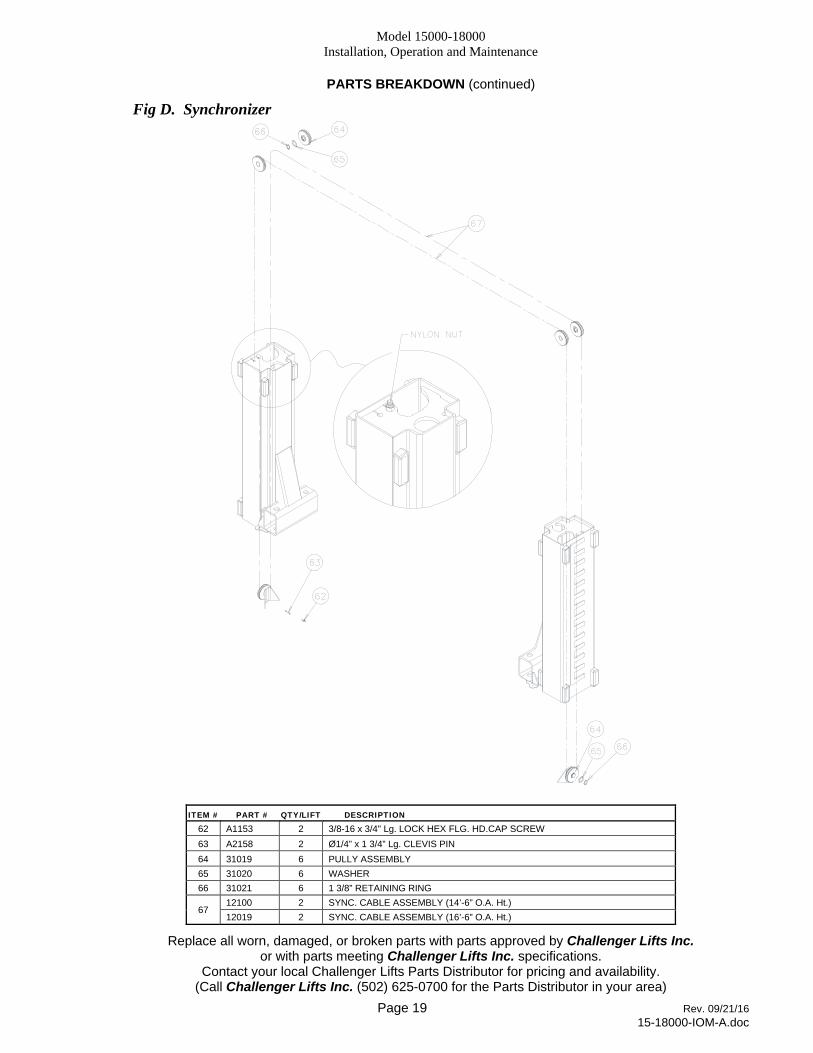
Fig D. Synchronizer
ITEM # PART # QTY/LIFT DESCRIPTION
62 A1153 2 3/8-16 x 3/4" Lg. LOCK HEX FLG. HD.CAP SCREW
63 A2158 2 Ø1/4” x 1 3/4” Lg. CLEVIS PIN
64 31019 6 PULLY ASSEMBLY
65 31020 6 WASHER
66 31021 6 1 3/8” RETAINING RING
67 12100 2 SYNC. CABLE ASSEMBLY (14’-6” O.A. Ht.)
12019 2 SYNC. CABLE ASSEMBLY (16’-6” O.A. Ht.)
Replace all worn, damaged, or broken parts with parts approved by Challenger Lifts Inc. or with parts meeting Challenger Lifts Inc. specifications.
Contact your local Challenger Lifts Parts Distributor for pricing and availability. (Call Challenger Lifts Inc. (502) 625-0700 for the Parts Distributor in your area)

Model 15000-18000 Installation, Operation and Maintenance
Page 20 Rev. 09/21/16 15-18000-IOM-A.doc
PARTS BREAKDOWN (continued)
Fig E. Carriage & Arms
ITEM # PART # QTY/LIFT DESCRIPTION
75 12021 8 SLIDE BLOCK
76 B12007-18 2 CARRIAGE WELD
77 B12046 4 ARM PIN WELD
78 B12162S 4 FOOT PAD ASSEMBLY – 15/18K Items (78A, 78B, 78C, 78D)
78A A1104-H 4 PAD
78B B12163S 4 FOOT PAD WELD
78C B17257 4 3 x 45mm ROUND WIRE RETAINING RING
78D B12067 4 THREADED INSERT
79 B12049 4 FEMALE ARM WELD
80 B12054 4 MALE ARM WELD
81 12084 4 1/2” INTERNAL TOOTH LOCKWASHER
82 12072 4 1/2"-13 x 5/8” SOCKET HD. C.S.
83 12060 4 LINK WELD
84 31112 8 1/2"-13 x 1 1/2” Lg. SOCKET HEAD CAP SCREW
85 31108 4 INSERT
86 31109 4 COMPRESSION SPRING
87 12096 4 SLEEVE WELD
88 B1084 4 45mm External Retaining Ring
89 B2026-3 2 DOOR GUARD
90 X10-088 4 M8 x 30 SOCKET HEAD CAPSCREW
B12048S-1 4 ARM ASSEMBLY – 15/18K Items (42, 77, 78, 79, 80, 81, 82,88)
Replace all worn, damaged, or broken parts with parts approved by Challenger Lifts Inc. or with parts meeting Challenger Lifts Inc. specifications.
Contact your local Challenger Lifts Parts Distributor for pricing and availability. (Call Challenger Lifts Inc. (502) 625-0700 for the Parts Distributor in your area)