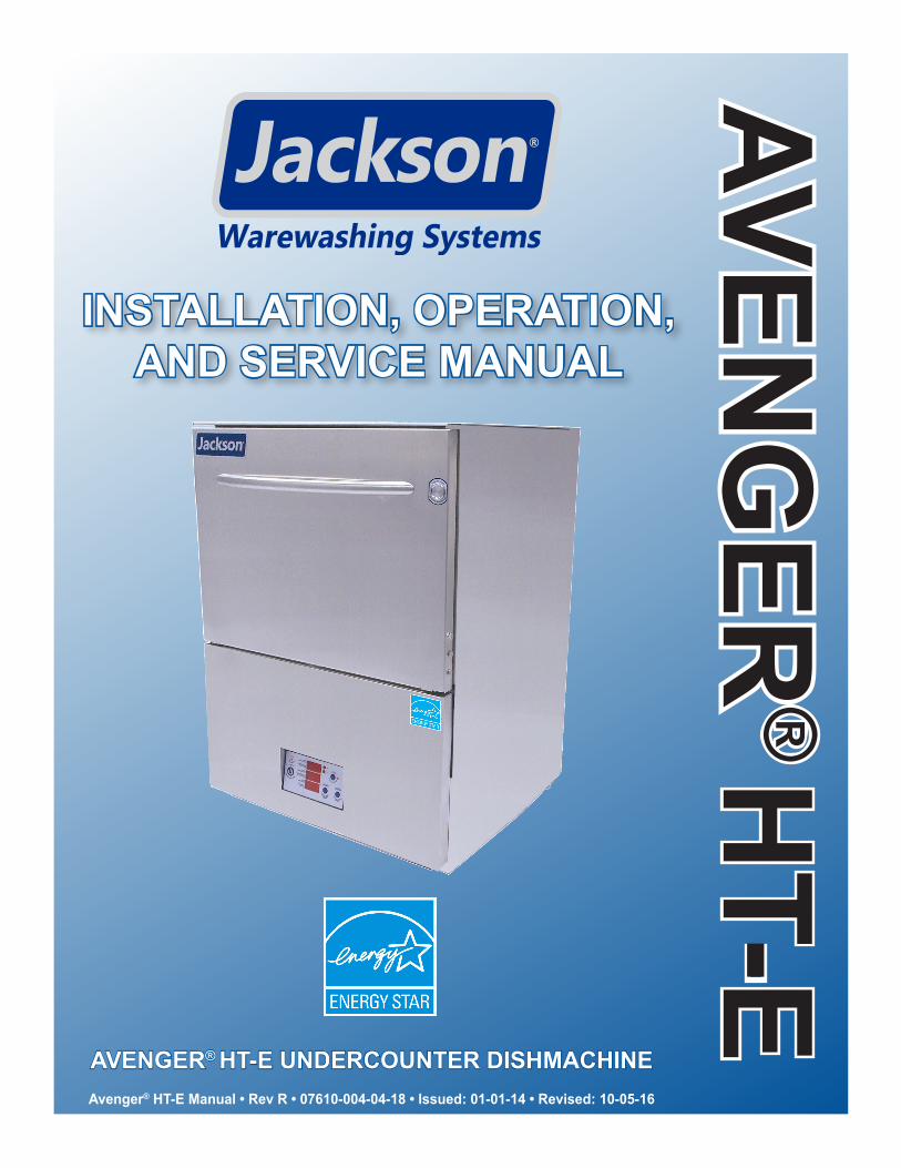
installation, operation, and service manual · avenger ® ht-e installation, operation, and service...
TRANSCRIPT
AVENG
ER®
HT-E
INSTALLATION, OPERATION,AND SERVICE MANUAL
Avenger® HT-E Manual • Rev R • 07610-004-04-18 • Issued: 01-01-14 • Revised: 10-05-16
AVENGER® HT-E UNDERCOUNTER DISHMACHINE

MANUFACTURER'S WARRANTY
ONE YEAR LIMITED PARTS AND LABOR WARRANTY
ALL NEW JACKSON DISHWASHERS ARE WARRANTED TO THE ORIGINAL PURCHASER TO BE FREE FROM DEFECTS IN MATERIAL OR WORKMANSHIP, UNDER NORMAL USE AND OPERATION FOR A PERIOD OF (1) ONE YEAR FROM DATE OF PURCHASE, BUT IN NO EVENT TO EXCEED (18) EIGHTEEN MONTHS FROM DATE OF SHIPMENT FROM THE FACTORY.
Jackson WWS agrees under this warranty to repair or replace, at its discretion, any original part which fails under normal use due to faulty material or workmanship during the warranty period, providing the equipment has been unaltered, and has been properly installed, maintained, and operated in accordance with the applicable factory instruction manual and failure is reported to an authorized service agency within the warranty period. This includes the use of factory-specified genuine replacement parts, purchased directly from a Jackson-authorized parts distributor or service agency. Use of generic replacement parts may create a hazard and void warranty certification.
The labor to repair or replace such failed part will be paid by Jackson WWS, within the continental United States, Hawaii, and Canada, during the warranty period provided a Jackson WWS authorized service agency, or those having prior authorization from the factory, performs the service. Any repair work by persons other than a Jackson WWS authorized service agency is the sole responsibility of the customer. Labor coverage is limited to regular hourly rates; overtime premiums and emergency service charges will not be paid by Jackson WWS.
Accessory components not installed by the factory carry a (1) one year parts warranty only. Accessory components such as table limit switches, pre-rinse units, etc. that are shipped with the unit and installed at the site are included. Labor to repair or replace these components is not covered by Jackson WWS.
This warranty is void if failure is a direct result from shipping, handling, fire, water, accident, misuse, acts of God, attempted repair by unauthorized persons, improper installation, if serial number has been removed or altered, or if unit is used for a purpose other than originally intended.
TRAVEL LIMITATIONS
Jackson WWS limits warranty travel time to (2) two hours and mileage to (100) one-hundred miles. Jackson WWS will not pay for travel time and mileage that exceeds this, or any additonal fees—such as those for air or boat travel—without prior authorization.
WARRANTY REGISTRATION
To register your product, go to www.jacksonwws.com or call 1-888-800-5672. Failure to register your product will void the warranty.
REPLACEMENT PARTS WARRANTY
Jackson replacement parts are warranted for a period of (90) ninety days from date of installation or (180) one-hundred-eighty days from the date of shipment from the factory, whichever occurs first.
PRODUCT CHANGES AND UPDATES
Jackson WWS reserves the right to make changes in the design and specification of any equipment as engineering or necessity requires.
THIS IS THE ENTIRE AND ONLY WARRANTY OF JACKSON WWS. JACKSON’S LIABILITY ON ANY CLAIM OF ANY KIND, INCLUDING NEGLIGENCE, WITH RESPECT TO THE GOODS OR SERVICES COVERED HEREUNDER, SHALL IN NO CASE EXCEED THE PRICE OF THE GOODS OR SERVICES OR PART THEREOF WHICH GIVES RISE TO THE CLAIM.
THERE ARE NO WARRANTIES, EXPRESSED OR IMPLIED, INCLUDING FOR FITNESS OR MERCHANTABILITY, THAT ARE NOT SET FORTH HEREIN, OR THAT EXTEND BEYOND THE DURATION HEREOF. UNDER NO CIRCUMSTANCES WILL JACKSON WWS BE LIABLE FOR ANY LOSS OR DAMAGE, DIRECT OR CONSEQUENTIAL, OR FOR DAMAGES IN THE NATURE OF PENALTIES, ARISING OUT OF THE USE OR INABILITY TO USE ANY OF ITS PRODUCTS.
ITEMS NOT COVERED
THIS WARRANTY DOES NOT COVER CLEANING OR DELIMING OF THE UNIT OR ANY COMPONENT SUCH AS, BUT NOT LIMITED TO, WASH ARMS, RINSE ARMS, OR STRAINERS AT ANYTIME. NOR DOES IT COVER ADJUSTMENTS SUCH AS, BUT NOT LIMITED TO, TIMER CAMS, THERMOSTATS, OR DOORS BEYOND (30) THIRTY DAYS FROM THE DATE OF INSTALLATION. IN ADDITION, THE WARRANTY WILL ONLY COVER REPLACEMENT WEAR ITEMS SUCH AS CURTAINS, DRAIN BALLS, DOOR GUIDES, OR GASKETS DURING THE FIRST (30) THIRTY DAYS AFTER INSTALLATION. ALSO, NOT COVERED ARE CONDITIONS CAUSED BY THE USE OF INCORRECT (NON-COMMERICAL) GRADE DETERGENTS, INCORRECT WATER TEMPERATURE OR PRESSURE, OR HARD WATER CONDITIONS.
i
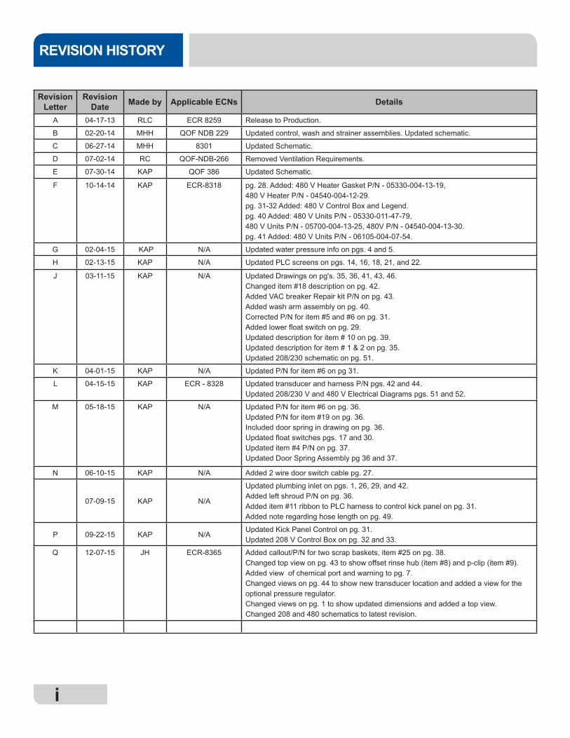
Revision Letter
Revision Date Made by Applicable ECNs Details
A 04-17-13 RLC ECR 8259 Release to Production.
B 02-20-14 MHH QOF NDB 229 Updated control, wash and strainer assemblies. Updated schematic.
C 06-27-14 MHH 8301 Updated Schematic.
D 07-02-14 RC QOF-NDB-266 Removed Ventilation Requirements.
E 07-30-14 KAP QOF 386 Updated Schematic.
F 10-14-14 KAP ECR-8318 pg. 28. Added: 480 V Heater Gasket P/N - 05330-004-13-19,480 V Heater P/N - 04540-004-12-29.pg. 31-32 Added: 480 V Control Box and Legend.pg. 40 Added: 480 V Units P/N - 05330-011-47-79,480 V Units P/N - 05700-004-13-25, 480V P/N - 04540-004-13-30.pg. 41 Added: 480 V Units P/N - 06105-004-07-54.
G 02-04-15 KAP N/A Updated water pressure info on pgs. 4 and 5.
H 02-13-15 KAP N/A Updated PLC screens on pgs. 14, 16, 18, 21, and 22.
J 03-11-15 KAP N/A Updated Drawings on pg's. 35, 36, 41, 43, 46.Changed item #18 description on pg. 42.Added VAC breaker Repair kit P/N on pg. 43.Added wash arm assembly on pg. 40.Corrected P/N for item #5 and #6 on pg. 31.Added lower float switch on pg. 29.Updated description for item # 10 on pg. 39.Updated description for item # 1 & 2 on pg. 35.Updated 208/230 schematic on pg. 51.
K 04-01-15 KAP N/A Updated P/N for item #6 on pg 31.
L 04-15-15 KAP ECR - 8328 Updated transducer and harness P/N pgs. 42 and 44.Updated 208/230 V and 480 V Electrical Diagrams pgs. 51 and 52.
M 05-18-15 KAP N/A Updated P/N for item #6 on pg. 36.Updated P/N for item #19 on pg. 36.Included door spring in drawing on pg. 36.Updated float switches pgs. 17 and 30.Updated item #4 P/N on pg. 37.Updated Door Spring Assembly pg 36 and 37.
N 06-10-15 KAP N/A Added 2 wire door switch cable pg. 27.
07-09-15 KAP N/A
Updated plumbing inlet on pgs. 1, 26, 29, and 42.Added left shroud P/N on pg. 36.Added item #11 ribbon to PLC harness to control kick panel on pg. 31.Added note regarding hose length on pg. 49.
P 09-22-15 KAP N/AUpdated Kick Panel Control on pg. 31.Updated 208 V Control Box on pg. 32 and 33.
Q 12-07-15 JH ECR-8365 Added callout/P/N for two scrap baskets, item #25 on pg. 38.Changed top view on pg. 43 to show offset rinse hub (item #8) and p-clip (item #9).Added view of chemical port and warning to pg. 7.Changed views on pg. 44 to show new transducer location and added a view for the optional pressure regulator.Changed views on pg. 1 to show updated dimensions and added a top view.Changed 208 and 480 schematics to latest revision.
REVISION HISTORY
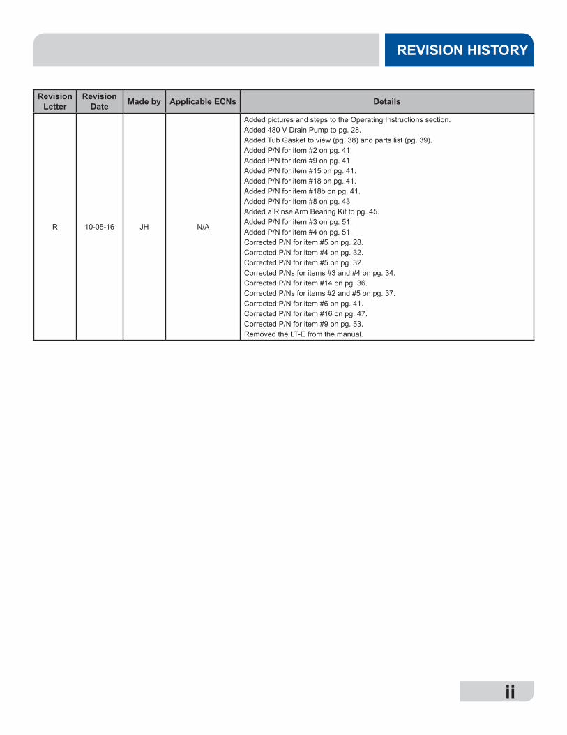
iiiiii
REVISION HISTORY
Revision Letter
Revision Date Made by Applicable ECNs Details
R 10-05-16 JH N/A
Added pictures and steps to the Operating Instructions section.Added 480 V Drain Pump to pg. 28.Added Tub Gasket to view (pg. 38) and parts list (pg. 39). Added P/N for item #2 on pg. 41.Added P/N for item #9 on pg. 41.Added P/N for item #15 on pg. 41.Added P/N for item #18 on pg. 41.Added P/N for item #18b on pg. 41.Added P/N for item #8 on pg. 43.Added a Rinse Arm Bearing Kit to pg. 45.Added P/N for item #3 on pg. 51.Added P/N for item #4 on pg. 51.Corrected P/N for item #5 on pg. 28.Corrected P/N for item #4 on pg. 32.Corrected P/N for item #5 on pg. 32.Corrected P/Ns for items #3 and #4 on pg. 34.Corrected P/N for item #14 on pg. 36.Corrected P/Ns for items #2 and #5 on pg. 37.Corrected P/N for item #6 on pg. 41.Corrected P/N for item #16 on pg. 47.Corrected P/N for item #9 on pg. 53.Removed the LT-E from the manual.
GUIDES
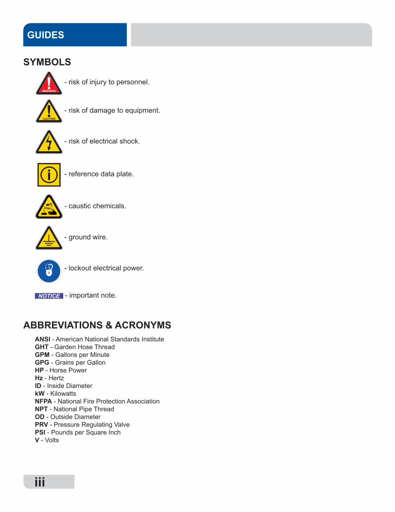
SYMBOLS
!CAUTION
!WARNING
NOTICE
- risk of injury to personnel.
- risk of damage to equipment.
- risk of electrical shock.
- lockout electrical power.
- reference data plate.
- important note.
i
- caustic chemicals.
ABBREVIATIONS & ACRONYMSANSI - American National Standards InstituteGHT - Garden Hose ThreadGPM - Gallons per MinuteGPG - Grains per GallonHP - Horse PowerHz - HertzID - Inside DiameterkW - KilowattsNFPA - National Fire Protection AssociationNPT - National Pipe ThreadOD - Outside DiameterPRV - Pressure Regulating ValvePSI - Pounds per Square InchV - Volts
- ground wire.
iii
iviv
AVENGER HT-EUndercounter dishmachine; high-temperature, hot-water
sanitizing, with a booster tank and detergent and rinse-aid chemical feeder pumps.
Model:
Serial No.:
Installation Date:
Service Rep. Name:
Phone Number:
NOMENCLATURE
The manufacturer provides technical support for all of the dishmachines detailed
in this manual. We strongly recommend that you refer to
this manual before making a call to our technical support staff. Please have this manual with you when you call so that our
staff can refer you, if necessary, to the proper page. Technical
support is not available on holidays. Contact technical
support toll free at 1-888-800-5672.
Technical support is available for service personnel only.
v
TABLE OF CONTENTS
SPECIFICATIONS Machine Dimensions .................................................................................................................. 1 Operating Parameters ................................................................................................................ 2 Electrical Requirements ............................................................................................................. 3
INSTRUCTIONS Installation .................................................................................................................................. 4 Chemical Feeder Pump Programming ....................................................................................... 8 Detergent Control ....................................................................................................................... 9 Operating .................................................................................................................................. 10 MAINTENANCE Preventative Maintenance ........................................................................................................ 14 Deliming ................................................................................................................................... 14 Troubleshooting ........................................................................................................................ 15 PLC Troubleshooting ............................................................................................................18
PARTS Machine Assembly ................................................................................................................... 28 Terminal Block Box Assembly .................................................................................................. 29 Control Panel ............................................................................................................................ 30 Control Kick Panel .................................................................................................................... 32 Control Panel Display ............................................................................................................... 33 208/230 V Control Box ............................................................................................................. 34 480 V Control Box .................................................................................................................... 36 Chemical Feeder Pump Assembly ........................................................................................... 37 Door Assembly ......................................................................................................................... 38 Wash & Drain Motor Assembly ................................................................................................. 40 Wash Arm Assembly ................................................................................................................. 42 Rinse Manifold Assembly ......................................................................................................... 43 Plumbing Assembly .................................................................................................................. 44 Rinse Tank Assembly ............................................................................................................... 46 Wash Pump Assembly .............................................................................................................. 48 SCHEMATICS 208/230 V, 50/60 HZ, 1-Phase ................................................................................................. 50 480 V, 60 HZ, 3-Phase ............................................................................................................. 51
107610-004-04-18-R
MACHINE DIMENSIONS SPECIFICATIONS
1634
[426 mm]
2558
[650 mm]
33 516
[846 mm]
14[356 mm]
Dish Clearance
678
[175 mm]
1458
[373 mm]
24 316
[615 mm]
LEGEND: A- Water Inlet - 3/4" Male Garden Hose Thread (M-GHT)(Connect to a true 1/2" ID water line) *Note: Water inlet dimensions for units supplied with a PRV will be *8 1/8, **10 1/2 B- Electrical Connection C- Drain Connection - 6' coiled drain hose. Shipped inside machine. Must be installed no more than 24" AFF All dimensions from floor can be increased1" with adjustable feet supplied.
FRONT
Door Open
TOP
C
B
B
878
[225 mm]
214
[57 mm]
See note above for water inlet dimensions, for amachine supplied with a PRV
414
[106 mm]
10[254 mm]
218
[53 mm]
26.3[668.1]
14
[6 mm]
4[102 mm]
4314
[1100 mm]
1[25 mm]above the floor.
207610-004-04-18-R
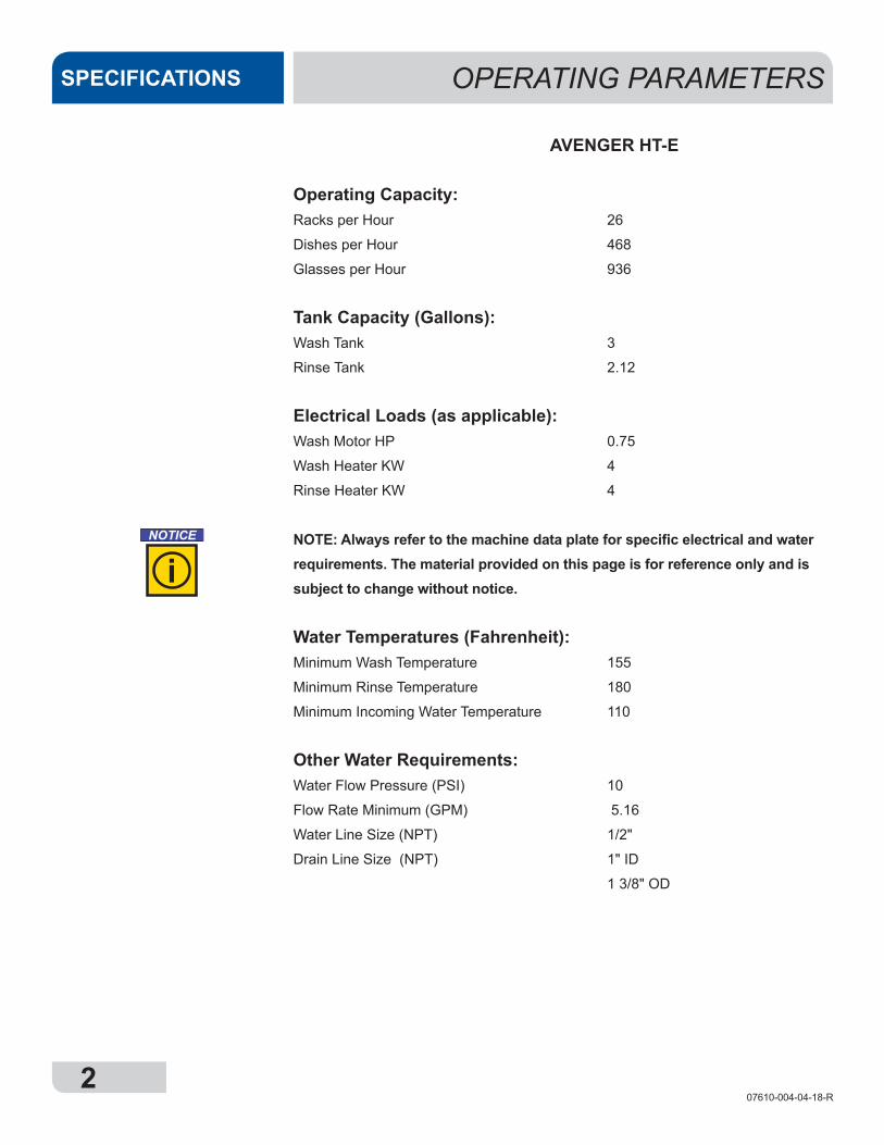
AVENGER HT-E
Operating Capacity:Racks per Hour 26
Dishes per Hour 468
Glasses per Hour 936
Tank Capacity (Gallons):Wash Tank 3
Rinse Tank 2.12
Electrical Loads (as applicable):Wash Motor HP 0.75
Wash Heater KW 4
Rinse Heater KW 4
NOTE: Always refer to the machine data plate for specific electrical and water requirements. The material provided on this page is for reference only and is subject to change without notice.
Water Temperatures (Fahrenheit):Minimum Wash Temperature 155
Minimum Rinse Temperature 180
Minimum Incoming Water Temperature 110
Other Water Requirements:Water Flow Pressure (PSI) 10
Flow Rate Minimum (GPM) 5.16
Water Line Size (NPT) 1/2"
Drain Line Size (NPT) 1" ID
1 3/8" OD
OPERATING PARAMETERSSPECIFICATIONS
NOTICE
i
307610-004-04-18-R
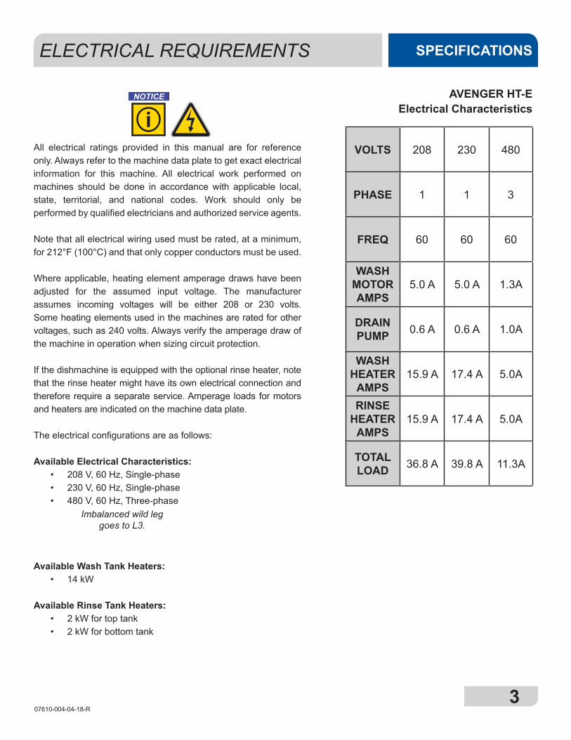
All electrical ratings provided in this manual are for reference only. Always refer to the machine data plate to get exact electrical information for this machine. All electrical work performed on machines should be done in accordance with applicable local, state, territorial, and national codes. Work should only be performed by qualified electricians and authorized service agents.
Note that all electrical wiring used must be rated, at a minimum, for 212°F (100°C) and that only copper conductors must be used.
Where applicable, heating element amperage draws have been adjusted for the assumed input voltage. The manufacturer assumes incoming voltages will be either 208 or 230 volts. Some heating elements used in the machines are rated for other voltages, such as 240 volts. Always verify the amperage draw of the machine in operation when sizing circuit protection.
If the dishmachine is equipped with the optional rinse heater, note that the rinse heater might have its own electrical connection and therefore require a separate service. Amperage loads for motors and heaters are indicated on the machine data plate.
The electrical configurations are as follows:
Available Electrical Characteristics:• 208 V, 60 Hz, Single-phase• 230 V, 60 Hz, Single-phase• 480 V, 60 Hz, Three-phase
Available Wash Tank Heaters:• 14 kW
Available Rinse Tank Heaters:• 2 kW for top tank • 2 kW for bottom tank
AVENGER HT-E Electrical Characteristics
ELECTRICAL REQUIREMENTS SPECIFICATIONS
VOLTS 208 230 480
PHASE 1 1 3
FREQ 60 60 60
WASH MOTOR AMPS
5.0 A 5.0 A 1.3A
DRAIN PUMP 0.6 A 0.6 A 1.0A
WASH HEATER
AMPS15.9 A 17.4 A 5.0A
RINSE HEATER
AMPS15.9 A 17.4 A 5.0A
TOTAL LOAD 36.8 A 39.8 A 11.3A
NOTICE
i
Imbalanced wild leg goes to L3.
407610-004-04-18-R
INSTRUCTIONSINSTALLATION
Before installing the unit, check packaging and machine for damage. Damaged packaging might be an indication of damage to the machine. If there is any type of damage to both packaging and unit, do not throw away the packaging. The dishmachine has been inspected at the factory before shipping and is expected to arrive in new, undamaged condition. However, rough handling by carriers or others might result in damage to the unit while in transit. If this occurs, do not return the unit to the manufacturer. Instead, contact the carrier and ask them to send a representative to the site to inspect the damage and request that an inspection report be completed.
Contact the carrier within 48 hours of receiving the machine as well as the dealer that sold you the unit.
The machine should be unboxed and removed from the pallet before installing. Open the front door and remove all of the materials from inside. Once unpacked, verify there are no missing parts. If a part is missing, contact the manufacturer immediately.
The dishmachine is designed to operate while level. This is important to prevent any damage to the machine during operation and to ensure the best possible results. The unit comes equipped with adjustable bullet feet which can be turned using a pair of pliers. Verify the unit is level from front-to-back and side-to-side before making any electrical or plumbing connections.
All plumbing connections must be made to adhere to local, state, territorial, and national codes. The installing plumber is responsible for ensuring the incoming water lines are flushed of debris before connecting to the machine. Note that chips and materials from cutting processes can become lodged in the solenoid valves and prevent them from opening or closing. Any valves that are found to be fouled or defective because of foreign matter left in the water line, and any subsequent damage, are not the responsibility of the manufacturer.
A water hardness test must be performed to determine if the HTS-11 (scale prevention and corrosion control) needs to be installed. A hardness test kit can be found on the warning tag that is attached to the incoming plumbing connection on the back of the machine. If water hardness is higher than 5 GPG, the HTS-11 will need to be installed. Please contact the manufacturer to purchase the HTS-11.
VISUAL INSPECTION
Do not throw away container if damage is
evident!
LEVEL THE DISHMACHINE
UNPACKING THE MACHINE
PLUMBING THE DISHMACHINE
A water hardness test must be performed.
The plumber must flush the incoming water line!
507610-004-04-18-R
INSTRUCTIONS INSTALLATION
WATER SUPPLY CONNECTIONS:
WATER HARDNESS GREATER THAN
5 GPG
WATER SUPPLY CONNECTION:
WATER HARDNESS OF 5 GPG OR LESS
PRESSURE REGULATOR
SHOCK ABSORBER
CONNECTING THE DRAIN LINE
If water hardness tests at greater than 5 GPG, install the HTS-11 into the water line (1/2” ID pipe size minimum) before the dishmachine’s incoming water connection point using copper pipe. Observe proper inlet/outlet water directions. Flow directions are molded into the top of the head. It is recommended that a water shut-off valve be installed before installing the HTS-11 to allow access for service. Plumb from the HTS-11 outlet to the incoming water connection point using copper pipe (or order the 1/2” ID flexible hose kit offered by manufacturer). The water supply must be capable of a minimum of 10 PSI “flow” pressure at the recommended temperature indicated on the data plate. See “Shock Absorber” section.
If water hardness tests at 5 GPG or less, install the water supply line (1/2” ID pipe size minimum) to the dishmachine’s incoming water connection point using copper pipe (or order the 1/2” ID flexible hose kit offered by the manufacturer). It is recommended that a water shut-off valve be installed in the water line between the main supply and the machine to allow access for service. The water supply line must be capable of a minimum of 10 PSI “flow” pressure at the recommended temperature indicated on the data plate.
The manufacturer has an optional water pressure regulator to accommodate areas where water pressure fluctuates or is higher than the recommended pressure. Take care not to confuse static pressure with flow pressure: static pressure is line pressure in a “no flow” condition (all valves and services are closed); flow pressure is the pressure in the fill line when the valve is opened during the cycle.
It is suggested that a shock absorber (not supplied) be installed on the incoming water line. This prevents water hammer (hydraulic shock)—induced by the solenoid valve as it operates—from causing damage to the equipment.
The dishmachine has a pumped (pressure) drain capable of pumping waste water to a height of 24” above the floor to the kitchen’s drain system. Each dishmachine is supplied with a drain hose. When installed, it will extend from the rear side of the ma-chine. There must be an air-gap between the machine drain line and the floor sink or drain. If a grease trap is required by code, it should have a flow capacity of 12 GPM.
After installing the incoming fill line and the drain line, slowly turn on the water supply to the machine. Check for any leaks and repair as required. All leaks must be repaired before operating the machine.
Take care not to confuse static pressure with
flow pressure!
PLUMBING CHECK
607610-004-04-18-R
INSTRUCTIONSINSTALLATION
ELECTRICAL POWER CONNECTIONS
Electrical and grounding conductors must comply with the applicable portions of the National Electric Code ANSI/NFPA 70 (latest edition) and/or other electrical codes.
The data plate is located at the left front side of the dishmachine. Refer to the data plate for machine operating requirements, machine voltage, total amperage, and serial number.
Remove the back panel to install the incoming power lines. This will require removing the screw at the bottom of the back panel with a phillips screwdriver. Remove the back panel and set aside. Install 3/4” conduit into the pre-punched holes in the back of the control box. Route power wires and connect to power block and grounding lug. Install the service wires (L1and L2) to the appropriate terminals as they are marked on the terminal block. Install the grounding wire into the lug provided. It is recom-mended that “DE-OX” or another similar anti-oxidation agent be used on all power connections.
Ensure that the power button is in the off position and apply power to dishmachine. Check the incoming power at the terminal block and ensure it corresponds with the voltage listed on the data plate. If not, contact a qualified service agency to examine the problem. Do not run dishmachine if voltage is too high or too low. Shut off the service breaker and advise all proper personnel of the location of the breaker and any problems. Replace the control box cover and tighten-down the screws.
This is a commercial dishmachine and reaches temperatures that can exceed those generated by a residential machine. Therefore, any surrounding countertops, cabinets, flooring material, and subfloor material must be designed and/or selected with these higher temperatures in mind.
NOTE: Any damage to surrounding area that is caused by heat and/or moisture to materials that are not recommended for higher temperatures will not be covered under warranty or by the manufacturer.
The temperature setpoints on this unit have been set at the factory. They should only be adjusted by an authorized service agent.
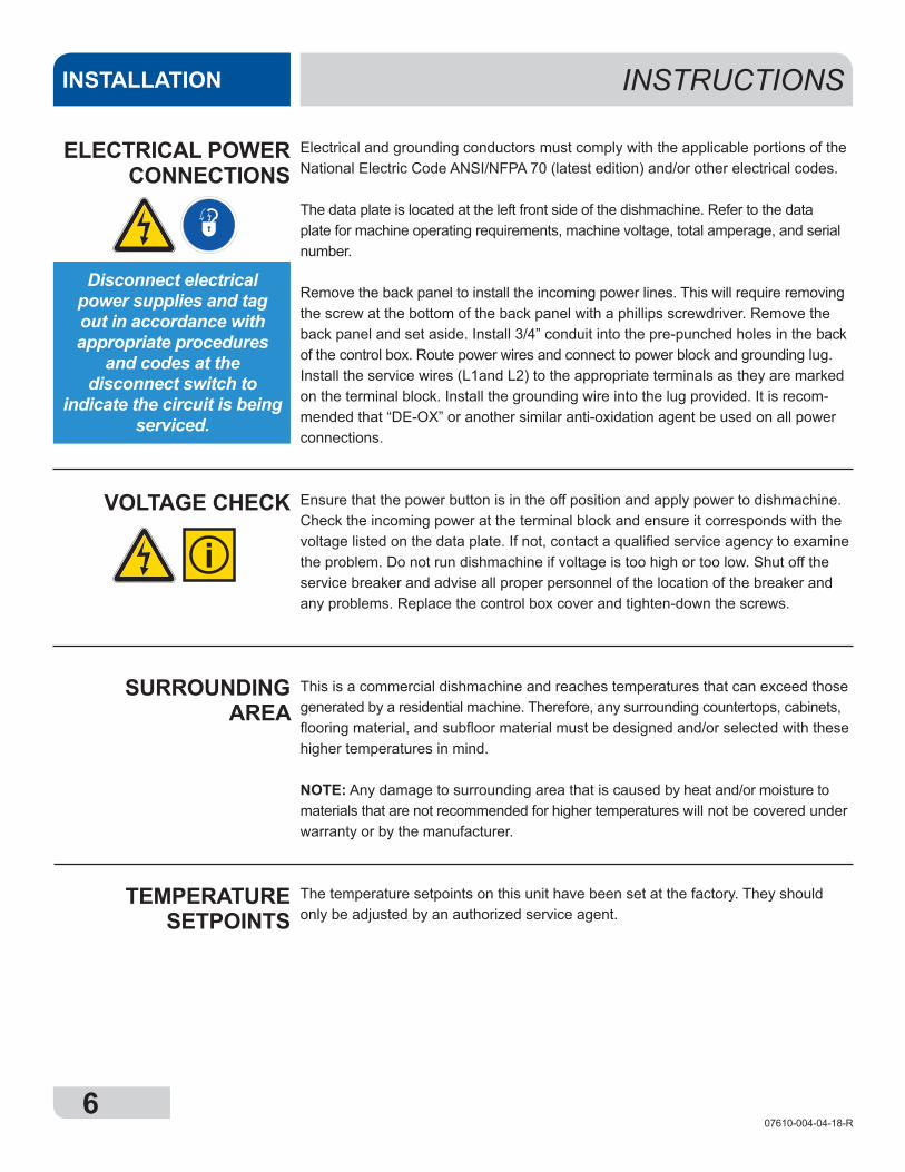
Disconnect electrical power supplies and tag out in accordance with appropriate procedures
and codes at the disconnect switch to
indicate the circuit is being serviced.
TEMPERATURESETPOINTS
SURROUNDING AREA
VOLTAGE CHECK
i
707610-004-04-18-R
INSTRUCTIONS INSTALLATION
CHEMICAL FEEDER EQUIPMENT
PRIMING CHEMICAL FEEDER PUMPS
WARNING: Some of the chemicals used in
dishwashing may cause chemical burns if they
come in contact with skin. Wear protective gear when handling these chemicals.
If any skin comes in contact with these
chemicals, immediately follow the instructions
provided with the chemicals for treatment.
TO PREPARE CHEMICAL FEEDER
PUMPS FOR OPERATION
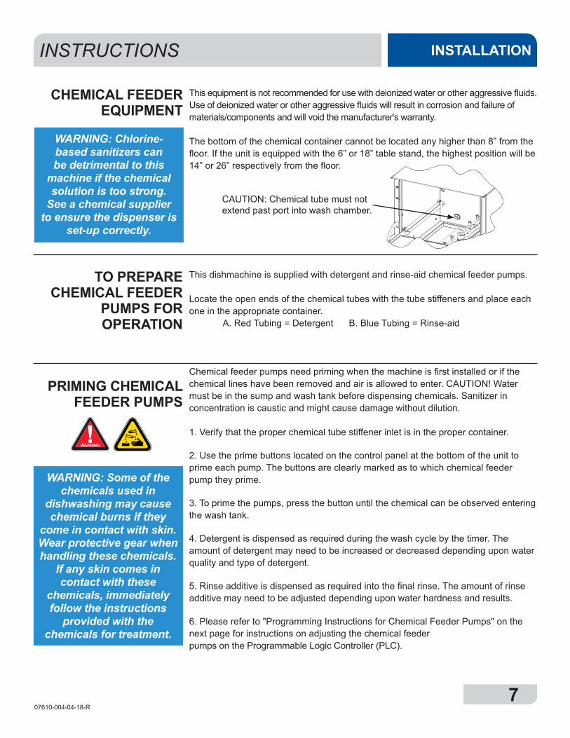
This equipment is not recommended for use with deionized water or other aggressive fluids. Use of deionized water or other aggressive fluids will result in corrosion and failure of materials/components and will void the manufacturer's warranty.
The bottom of the chemical container cannot be located any higher than 8” from the floor. If the unit is equipped with the 6” or 18” table stand, the highest position will be 14” or 26” respectively from the floor.
This dishmachine is supplied with detergent and rinse-aid chemical feeder pumps.
Locate the open ends of the chemical tubes with the tube stiffeners and place each one in the appropriate container. A. Red Tubing = Detergent B. Blue Tubing = Rinse-aid
Chemical feeder pumps need priming when the machine is first installed or if the chemical lines have been removed and air is allowed to enter. CAUTION! Water must be in the sump and wash tank before dispensing chemicals. Sanitizer in concentration is caustic and might cause damage without dilution. 1. Verify that the proper chemical tube stiffener inlet is in the proper container.
2. Use the prime buttons located on the control panel at the bottom of the unit to prime each pump. The buttons are clearly marked as to which chemical feeder pump they prime.
3. To prime the pumps, press the button until the chemical can be observed entering the wash tank.
4. Detergent is dispensed as required during the wash cycle by the timer. The amount of detergent may need to be increased or decreased depending upon water quality and type of detergent.
5. Rinse additive is dispensed as required into the final rinse. The amount of rinse additive may need to be adjusted depending upon water hardness and results.
6. Please refer to "Programming Instructions for Chemical Feeder Pumps" on the next page for instructions on adjusting the chemical feeder pumps on the Programmable Logic Controller (PLC).
WARNING: Chlorine-based sanitizers can be detrimental to this
machine if the chemical solution is too strong.
See a chemical supplier to ensure the dispenser is
set-up correctly.
CAUTION: Chemical tube must not extend past port into wash chamber.
!WARNING
807610-004-04-18-R
CHEMICAL FEEDER PUMP
PROGRAMMING (INSTALLATION
TECHNICIAN ONLY)
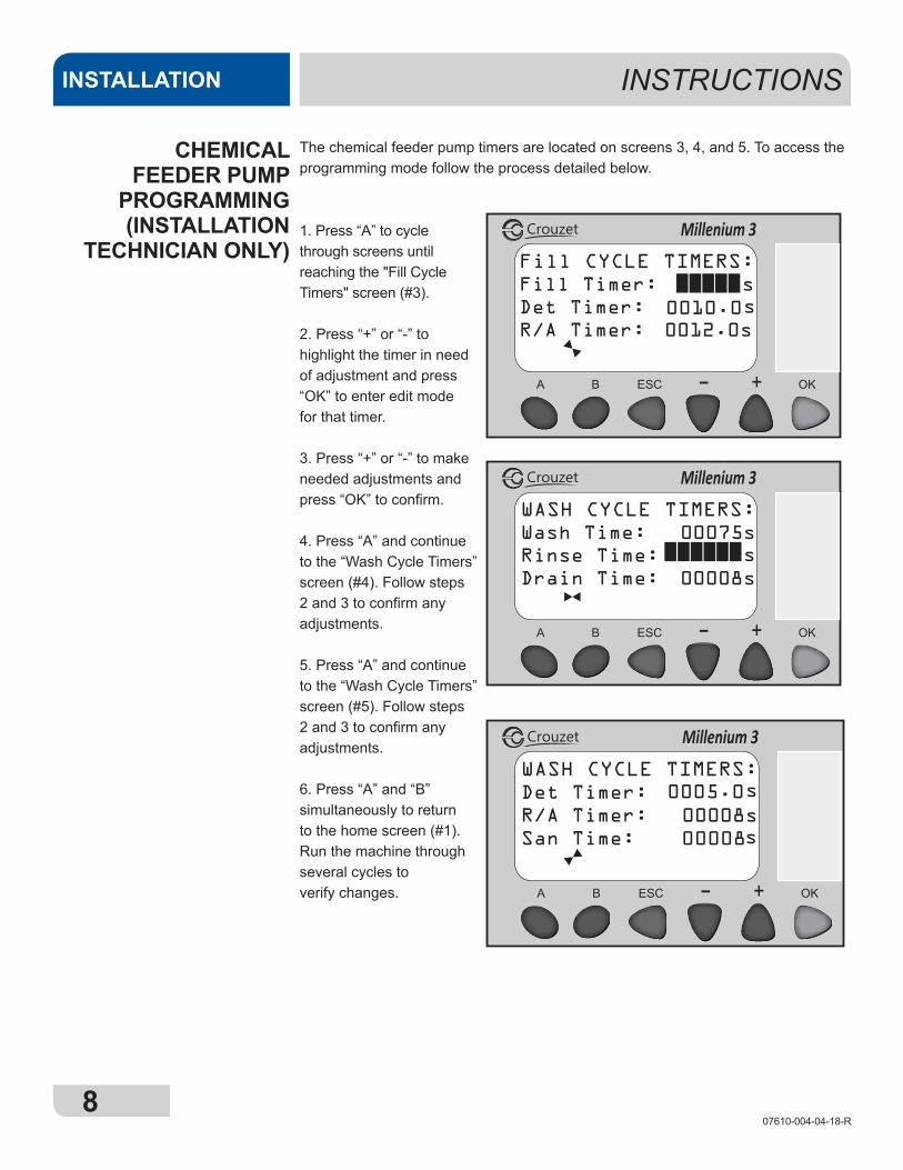
The chemical feeder pump timers are located on screens 3, 4, and 5. To access the programming mode follow the process detailed below.
INSTRUCTIONSINSTALLATION
1. Press “A” to cycle through screens until reaching the "Fill Cycle Timers" screen (#3).
2. Press “+” or “-” to highlight the timer in need of adjustment and press “OK” to enter edit mode for that timer.
3. Press “+” or “-” to make needed adjustments and press “OK” to confirm.
4. Press “A” and continue to the “Wash Cycle Timers” screen (#4). Follow steps 2 and 3 to confirm any adjustments.
5. Press “A” and continue to the “Wash Cycle Timers” screen (#5). Follow steps 2 and 3 to confirm any adjustments.
6. Press “A” and “B” simultaneously to return to the home screen (#1). Run the machine through several cycles to verify changes.
Fill CYCLE TIMERS:Fill Timer: sDet Timer:R/A Timer: 0012.0s
s
Millenium 3Crouzet
0010.0
WASH CYCLE TIMERS:Det Timer:R/A Timer: 00008sSan Time:
s
Millenium 3Crouzet
0005.0
s00008
WASH CYCLE TIMERS:Wash Time: 00075sRinse Time:Drain Time: 00008s
s
Millenium 3Crouzet
907610-004-04-18-R
INSTRUCTIONS INSTALLATION
Detergent usage and water hardness are two factors that contribute greatly to how efficiently this dishmachine will operate. Using detergent in the proper amount can become a source of substantial savings. A qualified water treatment specialist can determine what is needed for maximum efficiency from the detergent.
1. Hard water greatly affects the performance of the dishmachine, causing the amount of detergent required for washing to increase. If the machine is installed in an area with hard water, the manufacturer recommends the installation of water treatment equipment.
2. Deposited solids from hard water can cause spotting that will not be removed with a drying agent. Treated water will reduce this occurence.
3. Treated water might not be suitable for use in other areas of operation and it might be necessary to install a water treatment unit for the water going to the dish-machine only. Discuss this option with a qualified water treatment specialist.
4. Dishmachine operators should be properly trained on how much detergent is to be used per cycle. Meet with a water treatment specialist and detergent vendor to discuss a complete training program for operators.
5. Certain dishmachine models require that chemicals be provided for proper operation and sanitization. Some models might require the installation of third-party chemical feeders to introduce those chemicals to the machine. The manufacturer does not recommend or endorse any brand name of chemicals or chemical dispensing equipment. Contact a chemical supplier for questions.
6. Some dishmachines come equipped with integral solid detergent dispensers. These dispensers are designed to accommodate detergents in a certain-sized container. If applicable, relate this to a chemical supplier upon first contacting them.
7. Water temperature is an important factor in ensuring that the dishmachine functions properly, and the machine's data plate details what the minimum temperatures must be for the incoming water supply, the wash tank, and the rinse tank. If minimum requirements are not met, there is a possibility that dishes will not be clean or sanitized.
8. Instruct dishmachine operators to observe the required temperatures and to report when they fall below the minimum allowed. A loss of temperature can indicate a larger problem.
DETERGENT CONTROL
i
1007610-004-04-18-R
OPERATING INSTRUCTIONSOPERATION
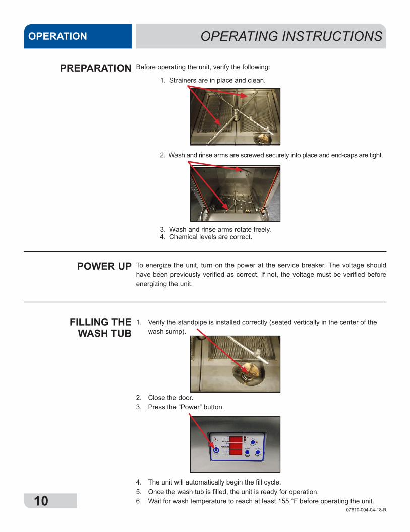
Before operating the unit, verify the following:
1. Strainers are in place and clean.
2. Wash and rinse arms are screwed securely into place and end-caps are tight.
3. Wash and rinse arms rotate freely. 4. Chemical levels are correct.
To energize the unit, turn on the power at the service breaker. The voltage should have been previously verified as correct. If not, the voltage must be verified before energizing the unit.
1. Verify the standpipe is installed correctly (seated vertically in the center of the wash sump).
2. Close the door.3. Press the “Power” button.
4. The unit will automatically begin the fill cycle.5. Once the wash tub is filled, the unit is ready for operation.6. Wait for wash temperature to reach at least 155 °F before operating the unit.
PREPARATION
POWER UP
FILLING THE WASH TUB
1107610-004-04-18-R
OPERATING INSTRUCTIONS OPERATION
Proper ware preparation will help ensure good results and fewer re-washes. If not done properly, ware might not come out clean and the efficiency of the dishmachine will be reduced. Putting unscrapped dishes into the machine affects its performance, so scraps should always be removed from ware before being loaded into a rack. Pre-rinsing and pre-soaking are good ideas, especially for silverware and casserole dishes.
Place cups and glasses upside-down in racks so they don't hold water during the cycle. The dishmachine sanitizes as well as cleans. To do this, ware must be properly prepared before being placed in the machine.
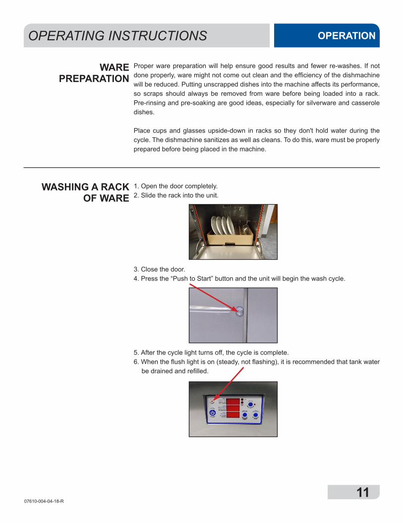
1. Open the door completely.2. Slide the rack into the unit.
3. Close the door.4. Press the “Push to Start” button and the unit will begin the wash cycle.
5. After the cycle light turns off, the cycle is complete.6. When the flush light is on (steady, not flashing), it is recommended that tank water
be drained and refilled.
WASHING A RACK OF WARE
WARE PREPARATION

1207610-004-04-18-R
Based on use, the strainers might become clogged with soil and debris as the workday progresses. Operators should regularly inspect the strainers to ensure they have not become clogged. Clogged strainers will reduce the washing capability of the machine. Instruct operators to clean out the strainers at regular intervals or as required by workload.
1. Open the door and remove the standpipe.
2. Close the door and turn the unit off by pushing the “Power” button.
3. The drain pump will activate and empty the unit of water.4. When draining stops, remove and clean the strainers and strainer frame and set
aside.
5. Unscrew the wash and rinse arms from their manifolds.
OPERATIONAL INSPECTION
SHUTDOWN AND CLEANING
OPERATING INSTRUCTIONSOPERATION
1307610-004-04-18-R
OPERATING INSTRUCTIONS OPERATION
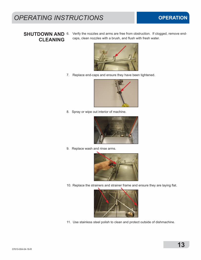
6. Verify the nozzles and arms are free from obstruction. If clogged, remove end-caps, clean nozzles with a brush, and flush with fresh water.
7. Replace end-caps and ensure they have been tightened.
8. Spray or wipe out interior of machine.
9. Replace wash and rinse arms.
10. Replace the strainers and strainer frame and ensure they are laying flat.
11. Use stainless steel polish to clean and protect outside of dishmachine.
SHUTDOWN AND CLEANING
1407610-004-04-18-R
PREVENTATIVE MAINTENANCEMAINTENANCE
The manufacturer of this dishmachine highly recommends that any maintenance and repairs not specifically discussed in this manual should be performed by qualified service personnel only. Performing maintenance on the dishmachine may void a warranty.
By following the operating and cleaning instructions in this manual, users should get the most efficient results from the dishmachine. As a reminder, here are some steps to ensure that the dishmachine is used properly:
1. Ensure that the water temperatures match those listed on the machine data plate (on the front-left of machine). 2. Remove as much soil as possible from ware before loading into racks.3. Ensure that strainers are in place, laying flat in tub, and free of soil and debris before operating the machine. To clean strainers, wipe them out with a rag and rinse under a faucet. For stubborn debris, a toothpick can be used. Do not beat strainers on waste cans; once bent, they will not work properly. 4. If hard water is present, install an HTS-11 into the water line connecting to the dishmachine (see "Plumbing the Dishmachine" section).5. Ensure that all wash and rinse arms are secure in the machine before operating.6. Ensure that the standpipe is seated before operating.7. Do not overfill racks.8. Ensure that glasses are placed upside-down in the rack.9. Ensure that all chemicals being injected into machine have been verified at the correct concentrations.10. Clean the machine at the end of every workday (see "Shutdown and Cleaning" section).11. Always contact a qualified service agency whenever a serious problem arises.12. Follow all safety procedures, whether listed in this manual or put forth by local, state, or national codes/regulations.
In order to maintain the dishmachine at its optimum performance level, lime and corrosion deposits must be removed. The frequency for deliming will be based on water conditions. A deliming solution is available from your chemical supplier. Read and follow all instructions on the label.
To delime the dishmachine:
1. Verify standpipe is in place, turn the unit on and allow it to complete a fill cycle.2. Verify water level. If low, switch the unit off then immediately back on (this will start a second fill cycle).3. Open the door and verify water level is above standpipe. Add deliming solution per the chemical supplier’s recommendation.4. Close the door and push the delime button on the front of the control panel.5. Run the machine for the period of time recommended by the chemical supplier.6. Press the delime button again and the pump will stop.7. Open the door and remove the standpipe.8. Press the power button to drain the machine and turn the unit off.9. Wait five minutes, then inspect the inside of the machine. If the machine is not delimed, run again.10. When clean, drain and refill the machine (Steps 1 and 2).11. Run in delime mode for 10 minutes to remove residual deliming solution.12. Drain and refill the machine.
PREVENTATIVE MAINTENANCE
DELIMING
NOTE: If this machine is equipped with an
HTS-11 scale prevention and corrosion control
device and lime is becoming a frequent
problem, the cartridge needs to be replaced.
To order a replacement cartridge, call the
manufacturer.
i
1507610-004-04-18-R
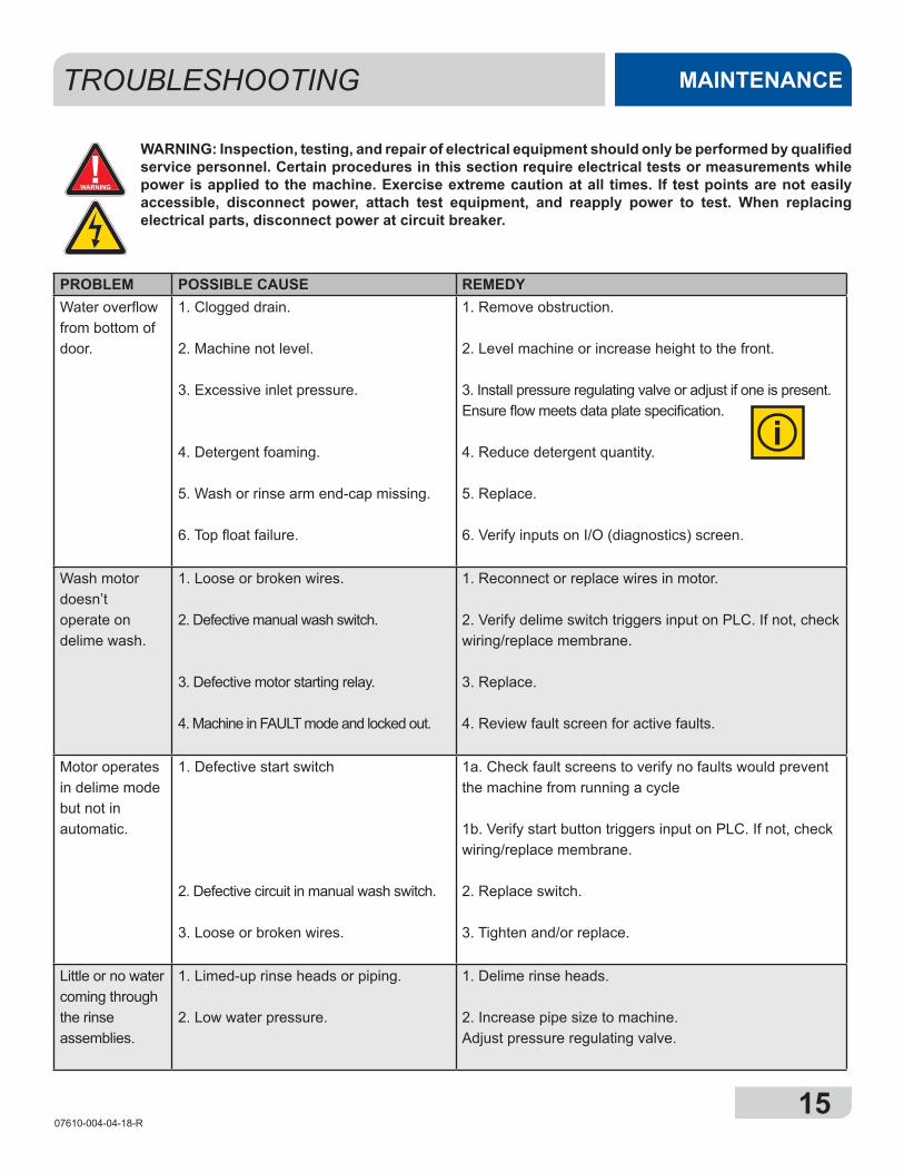
TROUBLESHOOTING MAINTENANCE
PROBLEM POSSIBLE CAUSE REMEDYWater overflow from bottom of door.
1. Clogged drain.
2. Machine not level.
3. Excessive inlet pressure.
4. Detergent foaming.
5. Wash or rinse arm end-cap missing.
6. Top float failure.
1. Remove obstruction.
2. Level machine or increase height to the front.
3. Install pressure regulating valve or adjust if one is present. Ensure flow meets data plate specification.
4. Reduce detergent quantity.
5. Replace.
6. Verify inputs on I/O (diagnostics) screen.
Wash motor doesn’t operate on delime wash.
1. Loose or broken wires.
2. Defective manual wash switch.
3. Defective motor starting relay.
4. Machine in FAULT mode and locked out.
1. Reconnect or replace wires in motor.
2. Verify delime switch triggers input on PLC. If not, check wiring/replace membrane.
3. Replace.
4. Review fault screen for active faults.
Motor operates in delime mode but not in automatic.
1. Defective start switch
2. Defective circuit in manual wash switch.
3. Loose or broken wires.
1a. Check fault screens to verify no faults would prevent the machine from running a cycle
1b. Verify start button triggers input on PLC. If not, check wiring/replace membrane.
2. Replace switch.
3. Tighten and/or replace.
Little or no water coming through the rinse assemblies.
1. Limed-up rinse heads or piping.
2. Low water pressure.
1. Delime rinse heads.
2. Increase pipe size to machine. Adjust pressure regulating valve.
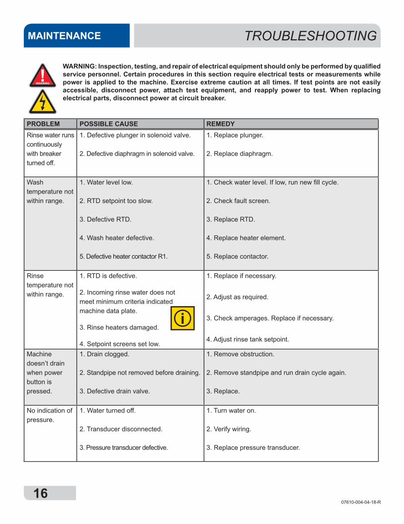
WARNING: Inspection, testing, and repair of electrical equipment should only be performed by qualified service personnel. Certain procedures in this section require electrical tests or measurements while power is applied to the machine. Exercise extreme caution at all times. If test points are not easily accessible, disconnect power, attach test equipment, and reapply power to test. When replacing electrical parts, disconnect power at circuit breaker.
!WARNING
i
1607610-004-04-18-R
Rinse water runs continuously with breaker turned off.
1. Defective plunger in solenoid valve.
2. Defective diaphragm in solenoid valve.
1. Replace plunger.
2. Replace diaphragm.
Wash temperature not within range.
1. Water level low.
2. RTD setpoint too slow.
3. Defective RTD.
4. Wash heater defective.
5. Defective heater contactor R1.
1. Check water level. If low, run new fill cycle.
2. Check fault screen.
3. Replace RTD.
4. Replace heater element.
5. Replace contactor.
Rinse temperature not within range.
1. RTD is defective.
2. Incoming rinse water does not meet minimum criteria indicated machine data plate.
3. Rinse heaters damaged.
4. Setpoint screens set low.
1. Replace if necessary.
2. Adjust as required.
3. Check amperages. Replace if necessary.
4. Adjust rinse tank setpoint.
Machine doesn’t drain when power button is pressed.
1. Drain clogged.
2. Standpipe not removed before draining.
3. Defective drain valve.
1. Remove obstruction.
2. Remove standpipe and run drain cycle again.
3. Replace.
No indication of pressure.
1. Water turned off.
2. Transducer disconnected.
3. Pressure transducer defective.
1. Turn water on.
2. Verify wiring.
3. Replace pressure transducer.
TROUBLESHOOTINGMAINTENANCE
PROBLEM POSSIBLE CAUSE REMEDY
WARNING: Inspection, testing, and repair of electrical equipment should only be performed by qualified service personnel. Certain procedures in this section require electrical tests or measurements while power is applied to the machine. Exercise extreme caution at all times. If test points are not easily accessible, disconnect power, attach test equipment, and reapply power to test. When replacing electrical parts, disconnect power at circuit breaker.
!WARNING
i
1707610-004-04-18-R
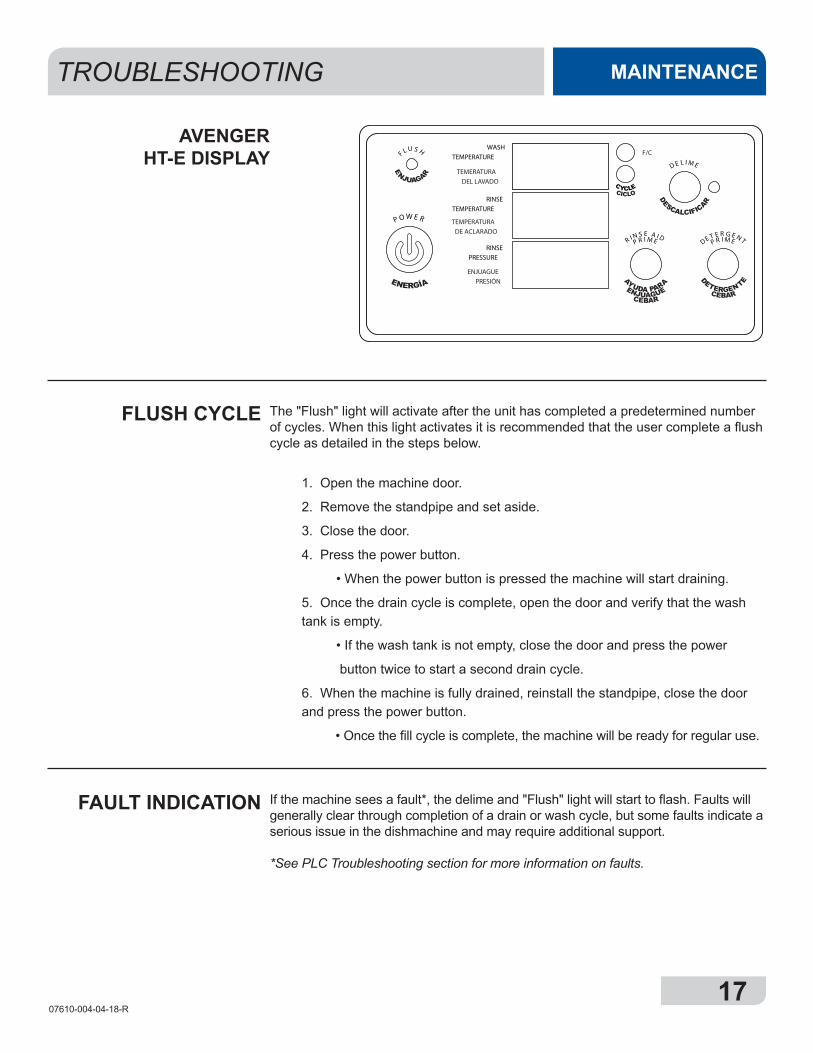
WASHTEMPERATURE
TEMERATURADEL LAVADO
RINSETEMPERATURE
TEMPERATURADE ACLARADO
RINSEPRESSURE
ENJUAGUEPRESIÓN
F/C
R I N S E A I DP R I M E
D E L I M E
DE T E R G E N TP R I M E
P O W E R
F L U S H
TROUBLESHOOTING MAINTENANCE
The "Flush" light will activate after the unit has completed a predetermined number of cycles. When this light activates it is recommended that the user complete a flush cycle as detailed in the steps below.
1. Open the machine door.
2. Remove the standpipe and set aside.
3. Close the door.
4. Press the power button.
• When the power button is pressed the machine will start draining.
5. Once the drain cycle is complete, open the door and verify that the wash tank is empty.
• If the wash tank is not empty, close the door and press the power
button twice to start a second drain cycle.
6. When the machine is fully drained, reinstall the standpipe, close the door and press the power button.
• Once the fill cycle is complete, the machine will be ready for regular use.
If the machine sees a fault*, the delime and "Flush" light will start to flash. Faults will generally clear through completion of a drain or wash cycle, but some faults indicate a serious issue in the dishmachine and may require additional support.
*See PLC Troubleshooting section for more information on faults.
FLUSH CYCLE
FAULT INDICATION
AVENGER HT-E DISPLAY
1807610-004-04-18-R
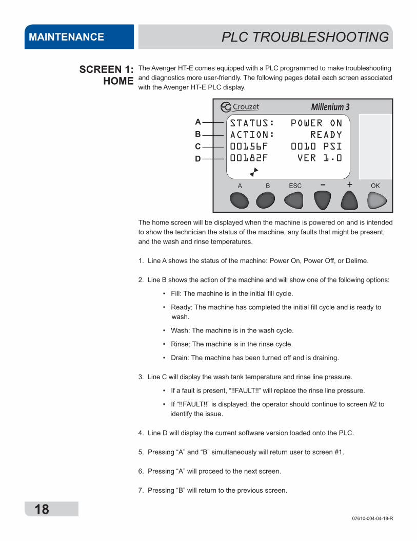
The Avenger HT-E comes equipped with a PLC programmed to make troubleshooting and diagnostics more user-friendly. The following pages detail each screen associated with the Avenger HT-E PLC display.
PLC TROUBLESHOOTINGMAINTENANCE
SCREEN 1:HOME
The home screen will be displayed when the machine is powered on and is intended to show the technician the status of the machine, any faults that might be present, and the wash and rinse temperatures.
1. Line A shows the status of the machine: Power On, Power Off, or Delime.
2. Line B shows the action of the machine and will show one of the following options:
• Fill: The machine is in the initial fill cycle.
• Ready: The machine has completed the initial fill cycle and is ready to wash.
• Wash: The machine is in the wash cycle.
• Rinse: The machine is in the rinse cycle.
• Drain: The machine has been turned off and is draining.
3. Line C will display the wash tank temperature and rinse line pressure.
• If a fault is present, “!!FAULT!!” will replace the rinse line pressure.
• If “!!FAULT!!” is displayed, the operator should continue to screen #2 to identify the issue.
4. Line D will display the current software version loaded onto the PLC.
5. Pressing “A” and “B” simultaneously will return user to screen #1.
6. Pressing “A” will proceed to the next screen.
7. Pressing “B” will return to the previous screen.
Millenium 3Crouzet
STATUS: POWER ONACTION: READY00156F 0010 PSI00182F VER 1.0
ABCD
1907610-004-04-18-R
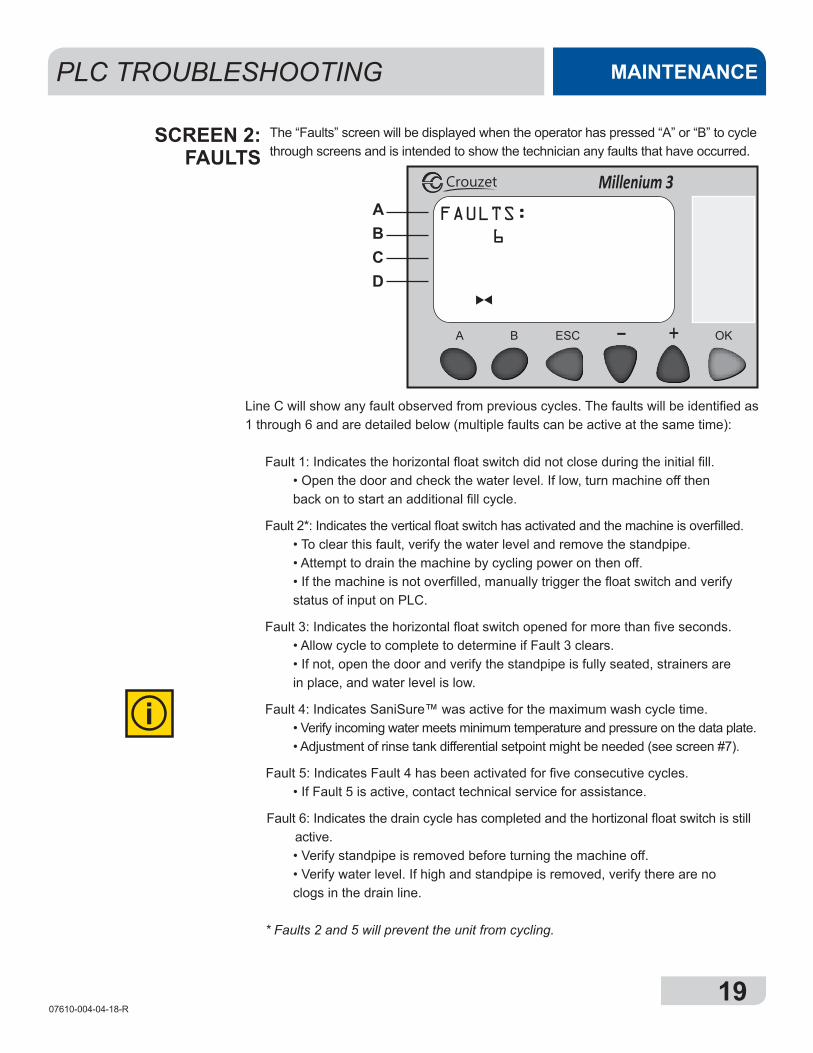
Millenium 3Crouzet
FAULTS: 6
The “Faults” screen will be displayed when the operator has pressed “A” or “B” to cycle through screens and is intended to show the technician any faults that have occurred.
ABCD
PLC TROUBLESHOOTING MAINTENANCE
SCREEN 2:FAULTS
Line C will show any fault observed from previous cycles. The faults will be identified as 1 through 6 and are detailed below (multiple faults can be active at the same time):
Fault 1: Indicates the horizontal float switch did not close during the initial fill. • Open the door and check the water level. If low, turn machine off then back on to start an additional fill cycle.
Fault 2*: Indicates the vertical float switch has activated and the machine is overfilled. • To clear this fault, verify the water level and remove the standpipe. • Attempt to drain the machine by cycling power on then off. • If the machine is not overfilled, manually trigger the float switch and verify status of input on PLC.
Fault 3: Indicates the horizontal float switch opened for more than five seconds. • Allow cycle to complete to determine if Fault 3 clears. • If not, open the door and verify the standpipe is fully seated, strainers are in place, and water level is low.
Fault 4: Indicates SaniSure™ was active for the maximum wash cycle time. • Verify incoming water meets minimum temperature and pressure on the data plate. • Adjustment of rinse tank differential setpoint might be needed (see screen #7).
Fault 5: Indicates Fault 4 has been activated for five consecutive cycles. • If Fault 5 is active, contact technical service for assistance.
Fault 6: Indicates the drain cycle has completed and the hortizonal float switch is still active. • Verify standpipe is removed before turning the machine off. • Verify water level. If high and standpipe is removed, verify there are no clogs in the drain line.
* Faults 2 and 5 will prevent the unit from cycling.
i
2007610-004-04-18-R
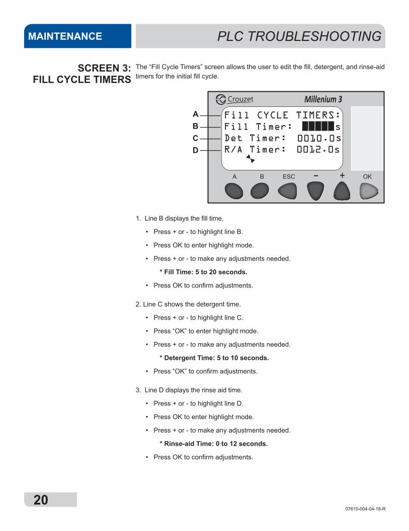
Fill CYCLE TIMERS:Fill Timer: sDet Timer:R/A Timer: 0012.0s
s
Millenium 3Crouzet
0010.0
The “Fill Cycle Timers” screen allows the user to edit the fill, detergent, and rinse-aid timers for the initial fill cycle.
ABCD
PLC TROUBLESHOOTINGMAINTENANCE
SCREEN 3:FILL CYCLE TIMERS
1. Line B displays the fill time.
• Press + or - to highlight line B.
• Press OK to enter highlight mode.
• Press + or - to make any adjustments needed.
* Fill Time: 5 to 20 seconds.
• Press OK to confirm adjustments.
2. Line C shows the detergent time.
• Press + or - to highlight line C.
• Press “OK” to enter highlight mode.
• Press + or - to make any adjustments needed.
* Detergent Time: 5 to 10 seconds.
• Press “OK” to confirm adjustments.
3. Line D displays the rinse aid time.
• Press + or - to highlight line D.
• Press OK to enter highlight mode.
• Press + or - to make any adjustments needed.
* Rinse-aid Time: 0 to 12 seconds.
• Press OK to confirm adjustments.
2107610-004-04-18-R
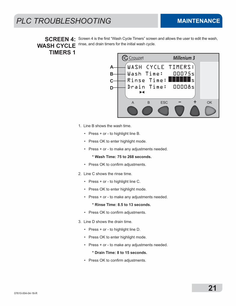
WASH CYCLE TIMERS:Wash Time: 00075sRinse Time:Drain Time: 00008s
s
Millenium 3Crouzet
Screen 4 is the first “Wash Cycle Timers” screen and allows the user to edit the wash, rinse, and drain timers for the initial wash cycle.
ABCD
PLC TROUBLESHOOTING MAINTENANCE
SCREEN 4:WASH CYCLE
TIMERS 1
1. Line B shows the wash time.
• Press + or - to highlight line B.
• Press OK to enter highlight mode.
• Press + or - to make any adjustments needed.
* Wash Time: 75 to 268 seconds.
• Press OK to confirm adjustments.
2. Line C shows the rinse time.
• Press + or - to highlight line C.
• Press OK to enter highlight mode.
• Press + or - to make any adjustments needed.
* Rinse Time: 8.5 to 13 seconds.
• Press OK to confirm adjustments.
3. Line D shows the drain time.
• Press + or - to highlight line D.
• Press OK to enter highlight mode.
• Press + or - to make any adjustments needed.
* Drain Time: 8 to 15 seconds.
• Press OK to confirm adjustments.
2207610-004-04-18-R
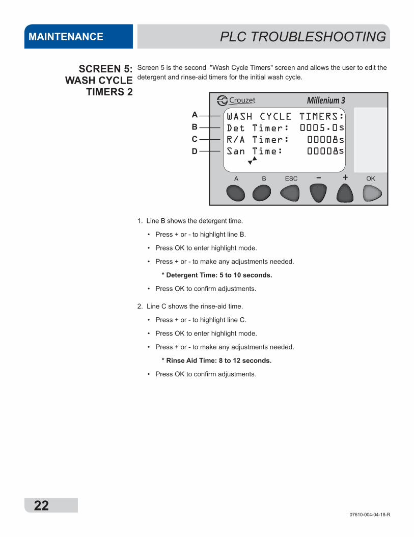
WASH CYCLE TIMERS:Det Timer:R/A Timer: 00008sSan Time:
s
Millenium 3Crouzet
0005.0
s00008
Screen 5 is the second "Wash Cycle Timers" screen and allows the user to edit the detergent and rinse-aid timers for the initial wash cycle.
ABCD
PLC TROUBLESHOOTINGMAINTENANCE
SCREEN 5:WASH CYCLE
TIMERS 2
1. Line B shows the detergent time.
• Press + or - to highlight line B.
• Press OK to enter highlight mode.
• Press + or - to make any adjustments needed.
* Detergent Time: 5 to 10 seconds.
• Press OK to confirm adjustments.
2. Line C shows the rinse-aid time.
• Press + or - to highlight line C.
• Press OK to enter highlight mode.
• Press + or - to make any adjustments needed.
* Rinse Aid Time: 8 to 12 seconds.
• Press OK to confirm adjustments.
2307610-004-04-18-R
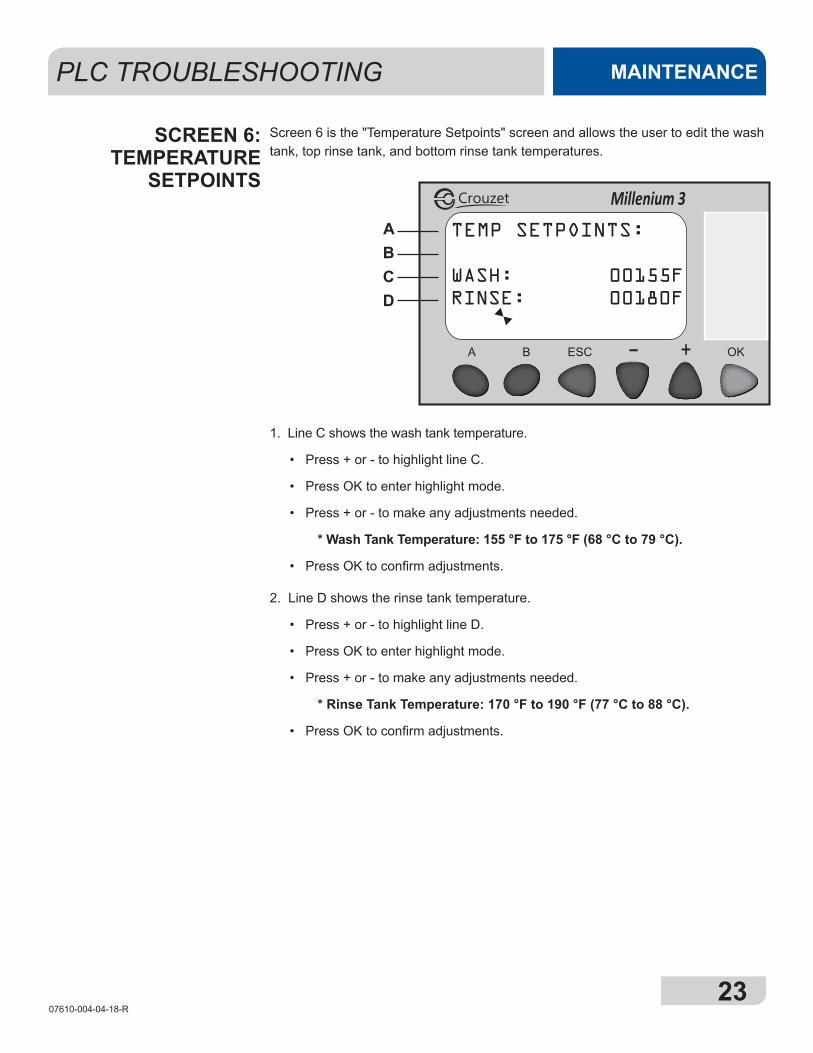
PLC TROUBLESHOOTING MAINTENANCE
Screen 6 is the "Temperature Setpoints" screen and allows the user to edit the wash tank, top rinse tank, and bottom rinse tank temperatures.
SCREEN 6:TEMPERATURE
SETPOINTS
1. Line C shows the wash tank temperature.
• Press + or - to highlight line C.
• Press OK to enter highlight mode.
• Press + or - to make any adjustments needed.
* Wash Tank Temperature: 155 °F to 175 °F (68 °C to 79 °C).
• Press OK to confirm adjustments.
2. Line D shows the rinse tank temperature.
• Press + or - to highlight line D.
• Press OK to enter highlight mode.
• Press + or - to make any adjustments needed.
* Rinse Tank Temperature: 170 °F to 190 °F (77 °C to 88 °C).
• Press OK to confirm adjustments.
TEMP SETPOINTS:
WASH: 00155FRINSE: 00180F
Millenium 3Crouzet
ABCD
2407610-004-04-18-R
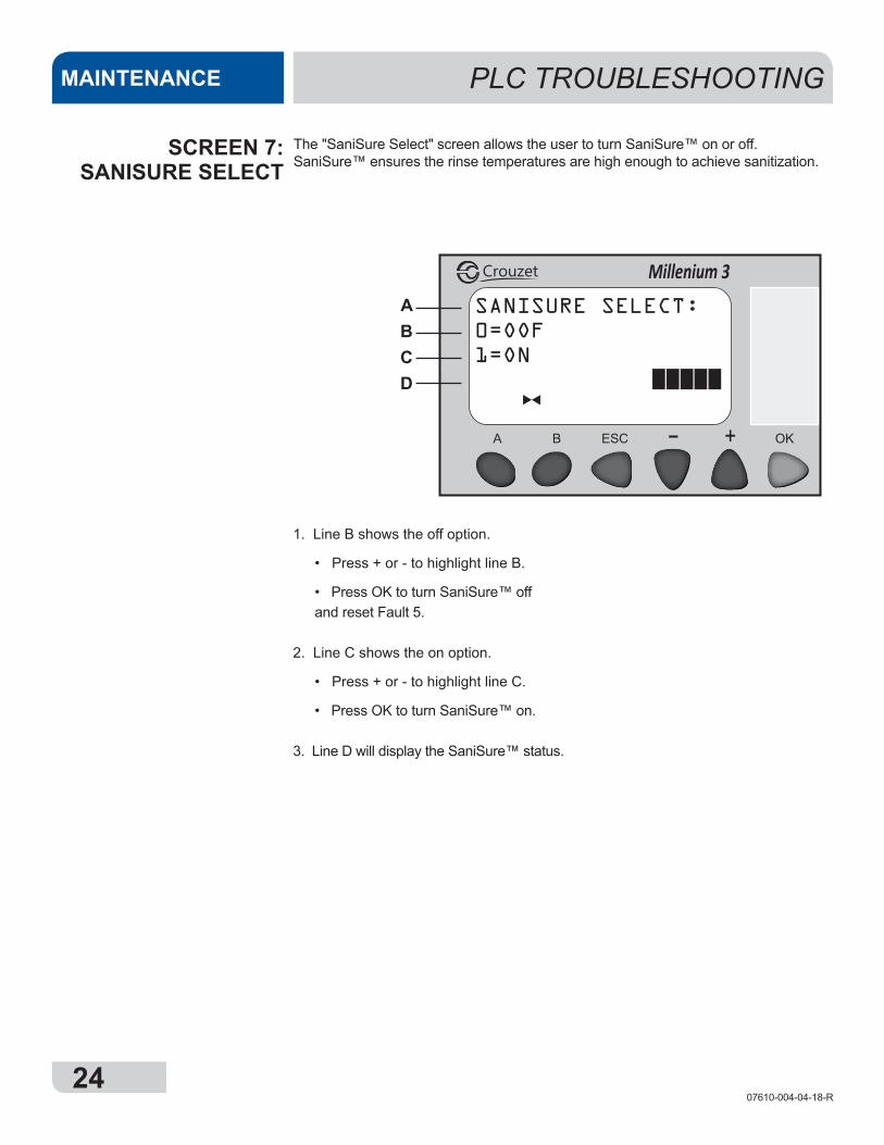
SANISURE SELECT:0=OOF1=ON
Millenium 3Crouzet
1. Line B shows the off option.
• Press + or - to highlight line B.
• Press OK to turn SaniSure™ off and reset Fault 5.
2. Line C shows the on option.
• Press + or - to highlight line C.
• Press OK to turn SaniSure™ on.
3. Line D will display the SaniSure™ status.
ABCD
PLC TROUBLESHOOTINGMAINTENANCE
SCREEN 7:SANISURE SELECT
The "SaniSure Select" screen allows the user to turn SaniSure™ on or off. SaniSure™ ensures the rinse temperatures are high enough to achieve sanitization.
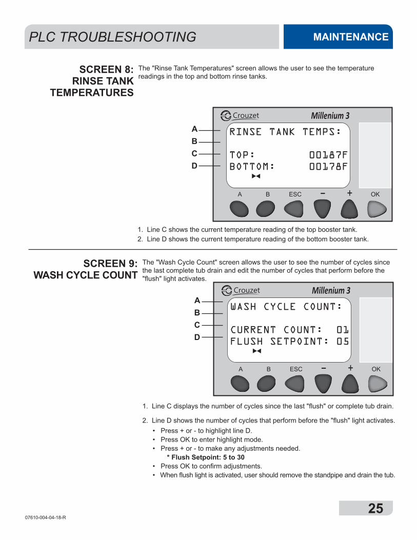
2507610-004-04-18-R
PLC TROUBLESHOOTING MAINTENANCE
1. Line C displays the number of cycles since the last "flush" or complete tub drain.
2. Line D shows the number of cycles that perform before the "flush" light activates. • Press + or - to highlight line D. • Press OK to enter highlight mode. • Press + or - to make any adjustments needed. * Flush Setpoint: 5 to 30 • Press OK to confirm adjustments. • When flush light is activated, user should remove the standpipe and drain the tub.
SCREEN 9:WASH CYCLE COUNT
RINSE TANK TEMPS:
TOP: 00187FBOTTOM: 00178F
Millenium 3Crouzet
1. Line C shows the current temperature reading of the top booster tank. 2. Line D shows the current temperature reading of the bottom booster tank.
ABCD
SCREEN 8:RINSE TANK
TEMPERATURES
The "Rinse Tank Temperatures" screen allows the user to see the temperature readings in the top and bottom rinse tanks.
The "Wash Cycle Count" screen allows the user to see the number of cycles since the last complete tub drain and edit the number of cycles that perform before the "flush" light activates.
WASH CYCLE COUNT:
CURRENT COUNT: 01FLUSH SETPOINT: 05
Millenium 3CrouzetABCD
2607610-004-04-18-R
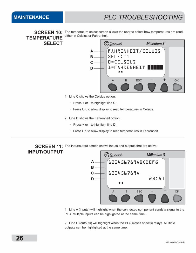
123456789ABCDEFG
123456789A 23:59
Millenium 3Crouzet
FAHRENHEIT/CELUISSELECTl0=CELSIUS1=FAHRENHEIT
Millenium 3Crouzet
1. Line A (inputs) will highlight when the connected component sends a signal to the PLC. Multiple inputs can be highlighted at the same time. 2. Line C (outputs) will highlight when the PLC closes specific relays. Multiple outputs can be highlighted at the same time.
1. Line C shows the Celsius option.
• Press + or - to highlight line C.
• Press OK to allow display to read temperatures in Celsius. 2. Line D shows the Fahrenheit option.
• Press + or - to highlight line D.
• Press OK to allow display to read temperatures in Fahrenheit.
ABCD
ABCD
PLC TROUBLESHOOTINGMAINTENANCE
26
SCREEN 11:INPUT/OUTPUT
SCREEN 10:TEMPERATURE
SELECT
The temperature select screen allows the user to select how temperatures are read, either in Celsius or Fahrenheit.
The input/output screen shows inputs and outputs that are active.
2707610-004-04-18-R
PLC TROUBLESHOOTING MAINTENANCE
27
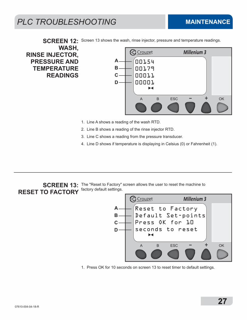
1. Line A shows a reading of the wash RTD.
2. Line B shows a reading of the rinse injector RTD.
3. Line C shows a reading from the pressure transducer.
4. Line D shows if temperature is displaying in Celsius (0) or Fahrenheit (1).
1. Press OK for 10 seconds on screen 13 to reset timer to default settings.
SCREEN 13:RESET TO FACTORY
SCREEN 12:WASH,
RINSE INJECTOR, PRESSURE AND TEMPERATURE
READINGS
Screen 13 shows the wash, rinse injector, pressure and temperature readings.
The "Reset to Factory" screen allows the user to reset the machine to factory default settings.
Reset to FactoryDefault Set-pointsPress OK for 10seconds to reset
Millenium 3Crouzet
00154001790001100001
Millenium 3Crouzet
ABCD
ABCD
2807610-004-04-18-R
NUM REVISION CONTROL# ORIG DRWNBY
DATE PARTS LIST
REV:PART NO:SCALE:
TITLE:DRAWN BY:
DATE:DATE:DATE:
CHECKED BY:APPROVED BY:
PART TO BE FREE FROM ALL BURRS AND SHARP EDGES
DO NOT SCALE DRAWING THIS PRINT IS THE PROPERTY OF JACKSON WWS,INC. AND IS SUBJECT TO RECALL AND RETURN ON DEMAND. ANY USE, DISCLOSURE, REPRODUCTION, DUPLICATION, TRACING, OR USE OF INFORMATION CONTAINED HEREIN IN ANY MANNER DETRIMENTAL TO THE INTEREST OF JACKSON WWS,INC. IS FORBIDDEN. ALL RIGHTS OF DESIGN RESERVED.
R.M.I. NO:
GAUGE:
MATERIAL:
USED ON:
NEXT ASSM:
3D MODEL?
TOLERANCESUNLESS OTHERWISE SPECIFIED
DIMENSIONS IN INCHES3 PL DECIMALS
2 PL DECIMALS
FRACTIONS 1/32
ANGLES 1/2
LET REVISION CONTROL# ORIG DRWNBY DATE
05700-004-00-98
A-MACHINE,AVENGER HT ES 208/60/1Roger Cox
10/3/2012
Yes ED WO
#:
1
ITEM QTY DESCRIPTION PART NUMBER1 1 Left Shroud 05700-003-37-04
2 1 Kick Panel Assembly 05700-004-05-62
3 1 Door Assembly 05700-004-04-21
4 1 Shroud Top 05700-003-37-06
5 1 Shroud Right 05700-003-37-05
6 1 Sump 05700-004-02-94
7 1Drain Pump - 208 V 04730-003-91-41
Drain Pump - 480 V 04730-004-18-40
81 Wash Motor Assembly - 208 V 05700-004-04-04
1 Wash Motor Assembly - 480 V 05700-004-19-74
9 1 Terminal Block Box Cover 05700-003-27-70
10 1Inlet Plumbing - 208 V 05700-004-09-03
Inlet Plumbing - 480 V 05700-004-11-43
11 1 Booster Assembly 05700-004-01-15
12 1 Rear Dress Panel (Optional) 05700-004-23-52
MACHINE ASSEMBLYPARTS
43
2
3
4
5
12 7
910
11
8
6
2907610-004-04-18-R
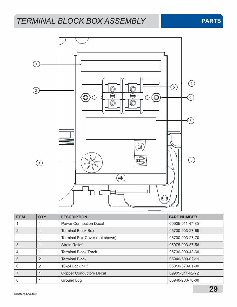
TERMINAL BLOCK BOX ASSEMBLY PARTS
ITEM QTY DESCRIPTION PART NUMBER1 1 Power Connection Decal 09905-011-47-35
2 1 Terminal Block Box 05700-003-27-69
1 Terminal Box Cover (not shown) 05700-003-27-70
3 1 Strain Relief 05975-003-37-56
4 1 Terminal Block Track 05700-000-43-60
5 2 Terminal Block 05940-500-02-19
6 2 10-24 Lock Nut 05310-373-01-00
7 1 Copper Conductors Decal 09905-011-62-72
8 1 Ground Lug 05940-200-76-00
6
7
54
8
1
3
2
3007610-004-04-18-R
CONTROL PANELPARTS
NUM REVISION CONTROL# ORIG DRWNBY
DATE PARTS LIST
REV:PART NO:SCALE:
TITLE:DRAWN BY:
DATE:DATE:DATE:
CHECKED BY:APPROVED BY:
PART TO BE FREE FROM ALL BURRS AND SHARP EDGES
DO NOT SCALE DRAWING THIS PRINT IS THE PROPERTY OF JACKSON WWS,INC. AND IS SUBJECT TO RECALL AND RETURN ON DEMAND. ANY USE, DISCLOSURE, REPRODUCTION, DUPLICATION, TRACING, OR USE OF INFORMATION CONTAINED HEREIN IN ANY MANNER DETRIMENTAL TO THE INTEREST OF JACKSON WWS,INC. IS FORBIDDEN. ALL RIGHTS OF DESIGN RESERVED.
R.M.I. NO:
GAUGE:
MATERIAL:
USED ON:
NEXT ASSM:
3D MODEL?
TOLERANCESUNLESS OTHERWISE SPECIFIED
DIMENSIONS IN INCHES3 PL DECIMALS
2 PL DECIMALS
FRACTIONS 1/32
ANGLES 1/2
LET REVISION CONTROL# ORIG DRWNBY DATE
05700-004-00-98
A-MACHINE,AVENGER HT ES 208/60/1Roger Cox
10/3/2012
Yes ED WO
#:
1
8
3
2
4 5
6
7
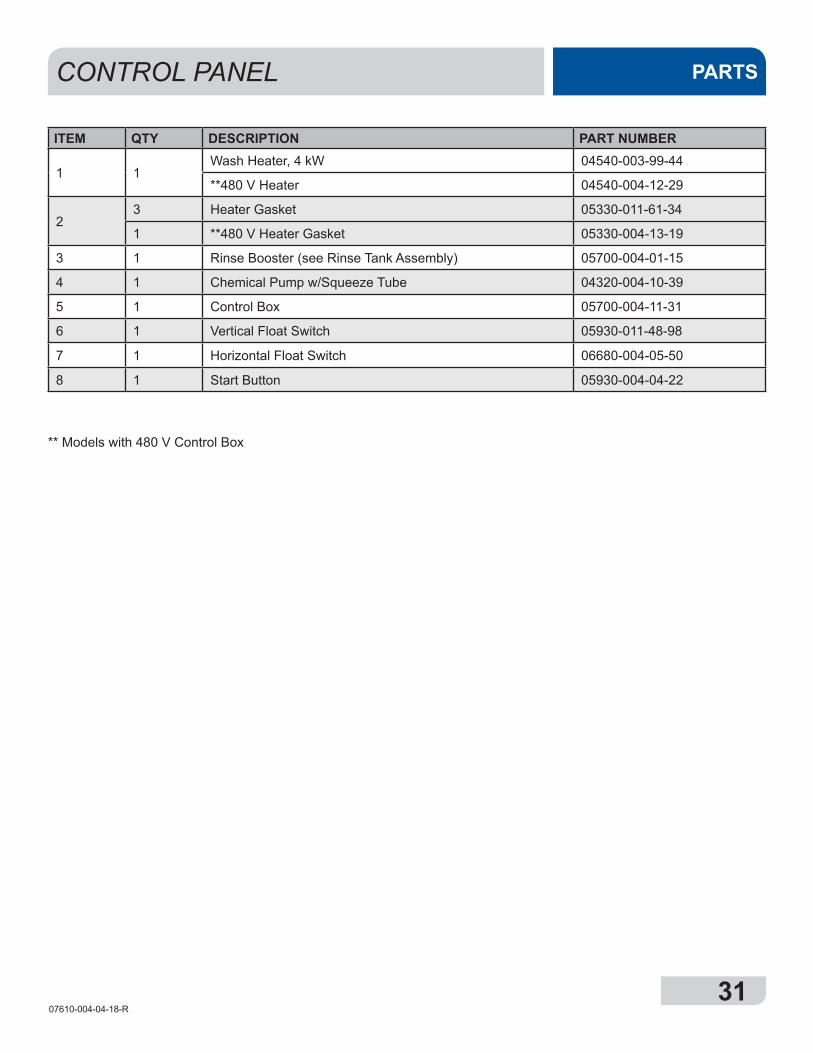
3107610-004-04-18-R
CONTROL PANEL PARTS
ITEM QTY DESCRIPTION PART NUMBER
1 1Wash Heater, 4 kW 04540-003-99-44
**480 V Heater 04540-004-12-29
23 Heater Gasket 05330-011-61-34
1 **480 V Heater Gasket 05330-004-13-19
3 1 Rinse Booster (see Rinse Tank Assembly) 05700-004-01-15
4 1 Chemical Pump w/Squeeze Tube 04320-004-10-39
5 1 Control Box 05700-004-11-31
6 1 Vertical Float Switch 05930-011-48-98
7 1 Horizontal Float Switch 06680-004-05-50
8 1 Start Button 05930-004-04-22
** Models with 480 V Control Box
3207610-004-04-18-R
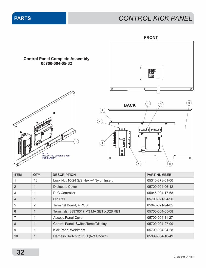
CONTROL KICK PANELPARTS
1
2
NOTE:DIELECTRIC COVER HIDDEN FOR CLARITY
3
5
4
6
7
8
9
1
2
NOTE:DIELECTRIC COVER HIDDEN FOR CLARITY
3
5
4
6
7
8
9
ITEM QTY DESCRIPTION PART NUMBER1 16 Lock Nut 10-24 S/S Hex w/ Nylon Insert 05310-373-01-00
2 1 Dielectric Cover 05700-004-06-12
3 1 PLC Controller 05945-004-17-68
4 1 Din Rail 05700-021-94-96
5 2 Terminal Board, 4 POS 05940-021-94-85
6 1 Terminals, 88970317 M3 MA SET XD26 RBT 05700-004-05-08
7 1 Access Panel Cover 05700-004-11-27
8 1 Control Panel, Switch/Temp/Display 05700-004-27-00
9 1 Kick Panel Weldment 05700-004-04-28
10 1 Harness Switch to PLC (Not Shown) 05999-004-10-49
1
2
NOTE:DIELECTRIC COVER HIDDEN FOR CLARITY
3
5
4
6
7
8
9
Control Panel Complete Assembly05700-004-05-62
FRONT
BACK
3307610-004-04-18-R
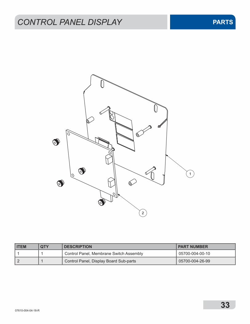
CONTROL PANEL DISPLAY PARTS
PART NUMBERDESCRIPTIONQTYITEM05700-004-00-10A-CONTROL PANEL, MEMBRANE SWITCH
ASSEMBLY11
05700-004-26-99A-CONTROL PANEL, DISPLAY BOARD SUB PARTS, AVENGER HT-E
12
NUM REVISION CONTROL# DRWNBY
ORIG DATE PARTS LIST
REV:PART NO:SCALE:
TITLE:DRAWN BY:
DATE:DATE:DATE:
CHECKED BY:APPROVED BY:
PART TO BE FREE FROM ALL BURRS AND SHARP EDGES
DO NOT SCALE DRAWING THIS PRINT IS THE PROPERTY OF JACKSON WWS,INC. AND IS SUBJECT TO RECALL AND RETURN ON DEMAND. ANY USE, DISCLOSURE, REPRODUCTION, DUPLICATION, TRACING, OR USE OF INFORMATION CONTAINED HEREIN IN ANY MANNER DETRIMENTAL TO THE INTEREST OF JACKSON WWS,INC. IS FORBIDDEN. ALL RIGHTS OF DESIGN RESERVED.
R.M.I. NO:
GAUGE:
MATERIAL:
USED ON:
NEXT ASSM:
3D MODEL?
TOLERANCESUNLESS OTHERWISE SPECIFIED
DIMENSIONS IN INCHES3 PL DECIMALS
2 PL DECIMALS
FRACTIONS 1/32
ANGLES 1/2
LET REVISION CONTROL# ORIG DRWNBY DATE
05700-004-27-00
A-CONTROL PANEL, SWITCH / TEMP, PSI DISPLAY, AVENGER HT-Etjones
9/11/2015
Yes AB WO
#:
RELEASED TO PRODUCTION TJ TJECN 8351A 11SEP15
1
2
ITEM QTY DESCRIPTION PART NUMBER1 1 Control Panel, Membrane Switch Assembly 05700-004-00-10
2 1 Control Panel, Display Board Sub-parts 05700-004-26-99
1
2
NOTE:DIELECTRIC COVER HIDDEN FOR CLARITY
3
5
4
6
7
8
9
3407610-004-04-18-R
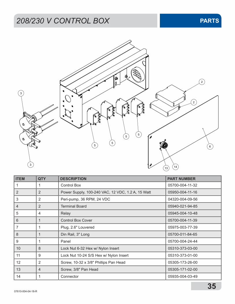
208/230 V CONTROL BOXPARTS
C1
HC
1
HC
2
HC
3
11 510 4
2
8
11
7
112
VIO/WHT ORG/WHT WHT/RED BLUE/WHT
9
2
2
5
3
3
55
5
13 14
6
C1
HC
1
HC
2
HC
3
11 510 4
2
8
11
7
112
VIO/WHT ORG/WHT WHT/RED BLUE/WHT
9
2
2
5
3
3
55
5
13 14
6
3507610-004-04-18-R
208/230 V CONTROL BOX PARTS
C1
HC
1
HC
2
HC
3
11 510 4
2
8
11
7
112
VIO/WHT ORG/WHT WHT/RED BLUE/WHT
9
2
2
5
3
3
55
5
13 14
6
ITEM QTY DESCRIPTION PART NUMBER1 1 Control Box 05700-004-11-32
2 2 Power Supply, 100-240 VAC, 12 VDC, 1.2 A, 15 Watt 05950-004-11-16
3 2 Peri-pump, 36 RPM, 24 VDC 04320-004-09-56
4 2 Terminal Board 05940-021-94-85
5 4 Relay 05945-004-10-48
6 1 Control Box Cover 05700-004-11-39
7 1 Plug, 2.6" Louvered 05975-003-77-39
8 1 Din Rail, 3" Long 05700-011-84-65
9 1 Panel 05700-004-24-44
10 8 Lock Nut 6-32 Hex w/ Nylon Insert 05310-373-03-00
11 9 Lock Nut 10-24 S/S Hex w/ Nylon Insert 05310-373-01-00
12 2 Screw, 10-32 x 3/8" Phillips Pan Head 05305-173-26-00
13 4 Screw, 3/8" Pan Head 05305-171-02-00
14 1 Connector 05935-004-03-49
3607610-004-04-18-R
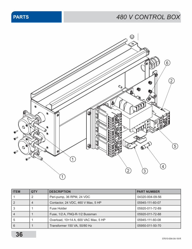
PARTS 480 V CONTROL BOX
PART NUMBERDESCRIPTIONQTYITEM04320-004-09-56PERIPUMP, 36 RPM 24VDC2105945-003-75-22CONTACTOR, 24VDC, 460V MAX, 5HP 4205945-003-75-17OVERLOAD, 10-14A, 600VAC MAX, (MTO3P)1305940-200-76-00LUG,LAMA214Q/PANDUIT GROUND1405920-011-72-89HOLDER, BM6031SQ SINPO FUSE BUSSMAN1705310-373-01-00NUT, LOCK10-24 S/S HEX W/NYLON IN7805920-011-72-88FUSE, 1/2 AMP FNQ-R-1/2 BUSSMAN11005940-002-31-31 11105940-002-31-33CONNECTOR, 2060364A SQ RECEPTACLE11205305-171-02-00SCREW 3/8 PAN HEAD41305975-011-65-51FITG.3219 .25/.546 LIQTITE11405975-003-37-56STRAIN RELIEF,1857 HEYCO RDD20111505700-004-09-28F-BRACKET, CTRL BOX REST11605700-011-88-01WEAR BUTTON, .50 DIA UHMW11705305-002-74-99SCREW, 6-32X1/2" SST FHMS81804730-011-39-01CLAMP, 5/8 NYLON W6NY-625-9-M T&B11905305-173-26-00SCREW, 10-32 X 3/8 PHILLIPS PAN HD182005700-004-11-34W-INNER PANEL, AVENGER HT-E CONT. BOX12105700-004-11-32W-CONTROL BOX, AVENGER HT-E-480V12205700-004-11-37F-DIN RAIL, AVENGER HT-E 2"12305700-004-11-36F-DIN RAIL, AVENGER HT-E 5-3/4"12405700-004-11-39W-COVER, CONT. BOX U-COUNTER 480V12505950-011-50-70TRANSFORMER 150 VA 50/80 H z126
NUM REVISION CONTROL# ORIG DRWNBY
DATE PARTS LIST
REV:PART NO:SCALE:
TITLE:DRAWN BY:
DATE:DATE:DATE:
CHECKED BY:APPROVED BY:
PART TO BE FREE FROM ALL BURRS AND SHARP EDGES
DO NOT SCALE DRAWING THIS PRINT IS THE PROPERTY OF JACKSON WWS,INC. AND IS SUBJECT TO RECALL AND RETURN ON DEMAND. ANY USE, DISCLOSURE, REPRODUCTION, DUPLICATION, TRACING, OR USE OF INFORMATION CONTAINED HEREIN IN ANY MANNER DETRIMENTAL TO THE INTEREST OF JACKSON WWS,INC. IS FORBIDDEN. ALL RIGHTS OF DESIGN RESERVED.
R.M.I. NO:
GAUGE:
MATERIAL:
USED ON:
NEXT ASSM:
3D MODEL?
TOLERANCESUNLESS OTHERWISE SPECIFIED
DIMENSIONS IN INCHES3 PL DECIMALS
2 PL DECIMALS
FRACTIONS 1/32
ANGLES 1/2
LET REVISION CONTROL# ORIG DRWNBY DATE
05700-004-11-35
A-CONTROL BOX, SLIDE 480VB.GAMBREL
2/10/2014
N/A
N/A
N/A
AVENGER HT-E
05700-004-11-40
Yes AC WO
#;
2
3
26
2 7
10
1
1
1
1
2 34
2
5
6
ITEM QTY DESCRIPTION PART NUMBER1 2 Peri-pump, 36 RPM, 24 VDC 04320-004-09-56
2 4 Contactor, 24 VDC, 460 V Max, 5 HP 05945-111-60-07
3 1 Fuse Holder 05920-011-72-89
4 1 Fuse, 1/2 A, FNQ-R-1/2 Bussman 05920-011-72-88
5 1 Overload, 10=14 A, 600 VAC Max, 5 HP 05945-111-60-08
6 1 Transformer 150 VA, 50/80 Hz 05950-011-50-70
3707610-004-04-18-R
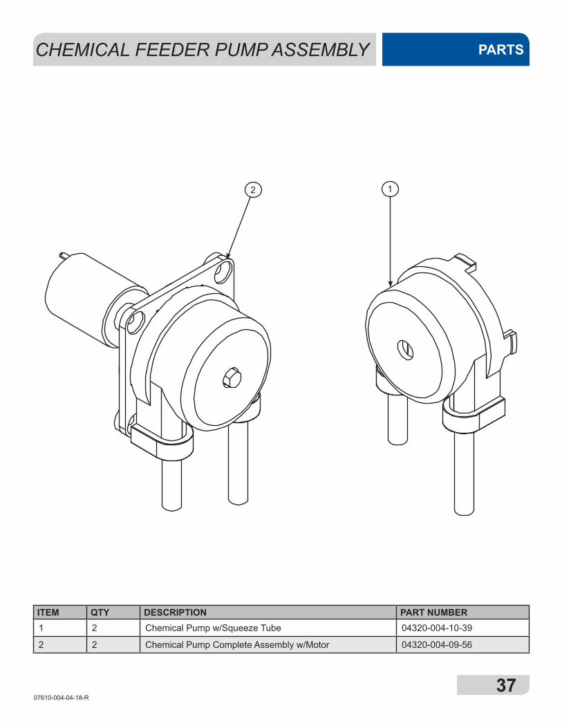
CHEMICAL FEEDER PUMP ASSEMBLY PARTS
12
ITEM QTY DESCRIPTION PART NUMBER1 2 Chemical Pump w/Squeeze Tube 04320-004-10-39
2 2 Chemical Pump Complete Assembly w/Motor 04320-004-09-56
3807610-004-04-18-R
8
12
16
15
14
13
11
4
10
9
7
17
18
6
5
4
3
2
1
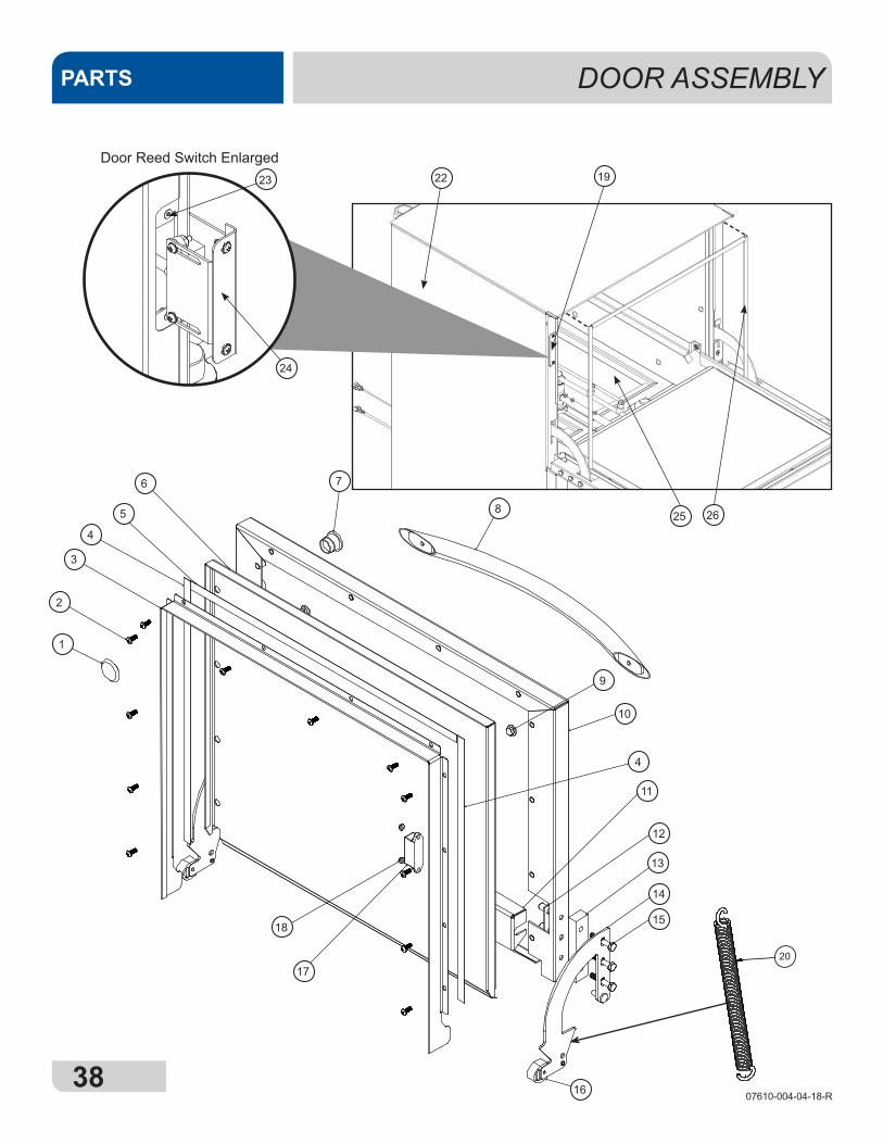
DOOR ASSEMBLYPARTS
19
PART NUMBER
DESCRIPTION
QTY
ITEM
05340-003-32-37
SPRING, DOOR
11
05700-003-32-84
TUBE, DOOR SPRING
22
PARTS LIST20
22
Door Reed Switch Enlarged
24
23
25 26
3907610-004-04-18-R
DOOR ASSEMBLY PARTS
ITEM QTY DESCRIPTION PART NUMBER1 1 Flush Mount Plug 05975-004-04-36
2 12 10-32 x 1/2” Phillips Pan Head Screw 05305-173-12-00
3 1 Door Channel Seal 05700-003-55-49
4 2 Left and Right Door Gasket 05330-003-58-36
5 1 Top Door Gasket 05330-003-58-35
6 1 Inner Door 05700-003-33-21
7 1 Start Button 05930-004-04-22
8 1 Door Handle 05700-003-26-62
9 2 1/4-20 x 3/8” Hex Head Bolt 05305-274-20-00
10 1 Outer Door Weldment 05700-003-33-37
11 1 Door Baffle 05700-003-33-38
12 2 Retaining Plate 05700-011-44-37
13 2 Hinge Spacer 05700-003-33-42
14 1 Left Hinge Weldment 05700-003-32-71
15 6 1/4-20 x 1 1/2” Hex Head Screw 05305-173-23-00
16 2 Door Hinge Stop 05700-003-32-55
17 1 Door Magnet 05930-002-88-42
18 2 6/32" Locknut 05310-373-03-00
1 Right Hinge Weldment (not shown) 05700-003-32-72
2 10-32 x 1/4” Screw (not shown) 05305-173-01-00
2 Washer (not shown) 05311-174-01-00
19 1 Door Reed Switch 05930-003-31-44
20 2 Door Spring Assembly 05700-003-32-85
21 1 2 Wire AVG Door Switch Cable 05700-004-08-26
22 1 Left Shroud 05700-003-37-04
23 1 Switch Mount Plate 05700-003-33-54
24 1 Door Switch and Bracket Assembly 05700-003-32-21
25 2 Scrap Basket 05700-004-09-43
26 1* Tub Gasket 05330-004-14-08
PART NUMBER
DESCRIPTION
QTY
ITEM
05340-003-32-37
SPRING, DOOR
11
05700-003-32-84
TUBE, DOOR SPRING
22
PARTS LIST
21
*Gasket will be received as one 5 1/2' piece and must be cut into three cut-to-fit pieces.
4007610-004-04-18-R
WASH & DRAIN MOTOR ASSEMBLYPARTS
10
11
1213
1
2
3
4
5
9
8
6
7
4107610-004-04-18-R
WASH & DRAIN MOTOR ASSEMBLY PARTS
ITEM QTY DESCRIPTION PART NUMBER1 1 Sump 05700-004-02-94
2 1 Sump Strainer 05700-004-03-73
3 1 Stand Pipe 05700-004-04-40
4 1 Manifold Gasket 05330-002-34-77
5 2 Wash Arm Assembly 05700-021-39-23
6 4 Wash Arm End-cap 05700-011-35-92
7 1 Wash Halo 05700-004-03-22
8 39 Locknut, 1/4-20 Hex w/Nylon Insert 05310-374-01-00
9 1 Wash Manifold 05700-004-08-96
10 1 Pump Assembly w/Mounting Bracket and Hoses 05700-004-04-04
11 1 Drain Pump 04730-003-91-41
12 1 Drain Hose 05700-004-08-21
13 3 Clamp, Reg. Range 1 1/16" to 2" 04730-719-18-00
4207610-004-04-18-R
3
1
2
4
WASH ARM ASSEMBLYPARTS
ITEM QTY DESCRIPTION PART NUMBERComplete Wash Arm Assembly 05700-021-39-23
1 1 Wash Arm 05700-021-46-58
2 1 Bearing, Assembly 05700-021-35-97
3 1 O-Ring 05330-002-60-69
4 2 Wash Arm End-cap 05700-011-35-92
4307610-004-04-18-R
2
3
6
7 3
1
5
4
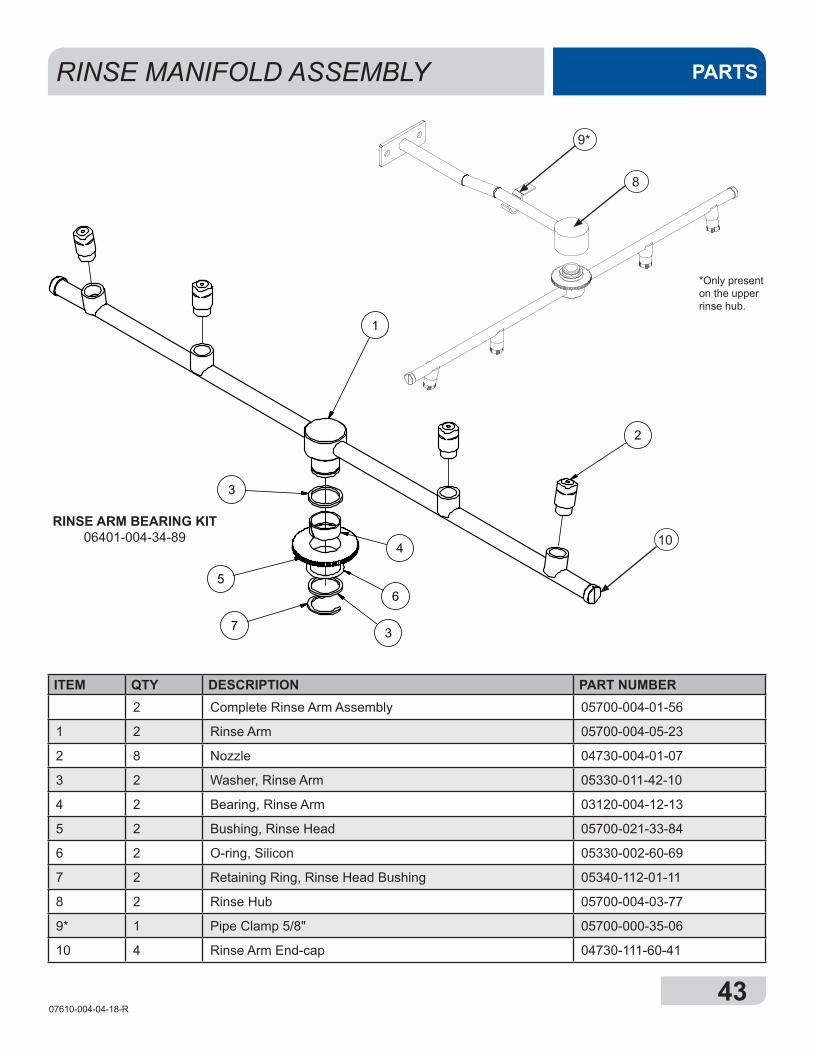
RINSE MANIFOLD ASSEMBLY PARTS
ITEM QTY DESCRIPTION PART NUMBER2 Complete Rinse Arm Assembly 05700-004-01-56
1 2 Rinse Arm 05700-004-05-23
2 8 Nozzle 04730-004-01-07
3 2 Washer, Rinse Arm 05330-011-42-10
4 2 Bearing, Rinse Arm 03120-004-12-13
5 2 Bushing, Rinse Head 05700-021-33-84
6 2 O-ring, Silicon 05330-002-60-69
7 2 Retaining Ring, Rinse Head Bushing 05340-112-01-11
8 2 Rinse Hub 05700-004-03-77
9* 1 Pipe Clamp 5/8" 05700-000-35-06
10 4 Rinse Arm End-cap 04730-111-60-41
8
9*
*Only present on the upper rinse hub.
10RINSE ARM BEARING KIT
06401-004-34-89
4407610-004-04-18-R
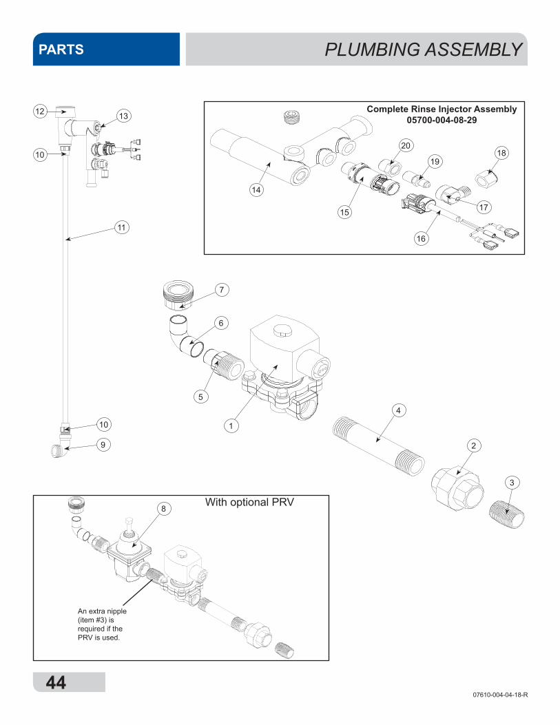
PLUMBING ASSEMBLYPARTS
Complete Rinse Injector Assembly05700-004-08-29
20
14
With optional PRV
6
54
3
2
1
1918
17
16
15
1312
10
11
10
9
8
7
An extra nipple (item #3) is required if the PRV is used.
4507610-004-04-18-R
PLUMBING ASSEMBLY PARTS
ITEM QTY DESCRIPTION PART NUMBER1 1 Valve, 1/2" 04810-003-71-56
2 1 Union, 1/2" x 1/2" Brass 04730-003-62-44
3 1 Nipple, 1/2" Close Brass 04730-207-15-00
4 1 Nipple, 1/2" x 4" NPT Brass 04730-207-04-00
5 1 Adapter, 1/2" Fitting, Male 04730-011-59-53
6 1 Elbow, 1/2" S. CU to FTG 04730-406-31-01
7 1 Hose Adapter 04720-004-24-68
8 1 PRV, 1/2" (Optional) 04820-004-09-37
9 1 Elbow, 90 Degree 1/2" Street Brass 04730-206-08-00
10 2 Adapter, Male (CU to MSPS) 04730-401-03-01
11 1 Copper Tube, 1/2" x 19.5" Long 05700-011-59-84
12 1 Vacuum Breaker, 1/2" Brass 04820-003-06-13
13 1 Fitting, 1/4" Brass Nut/Sleeve 05310-924-02-05
14 1 Rinse Injector 05700-004-08-28
15 1 Pressure Transducer 05945-004-17-01
16 1 Harness, Pressure Transducer 05999-004-21-58
17 1 Fitting, Outlet Elbow 04820-111-51-18
18 1 Nut, Tube 1/8" PP 04730-011-59-45
19 1 Check Valve 04820-111-51-14
20 1 Bushing, 1/4" x 1/8" 04730-003-05-61
4607610-004-04-18-R
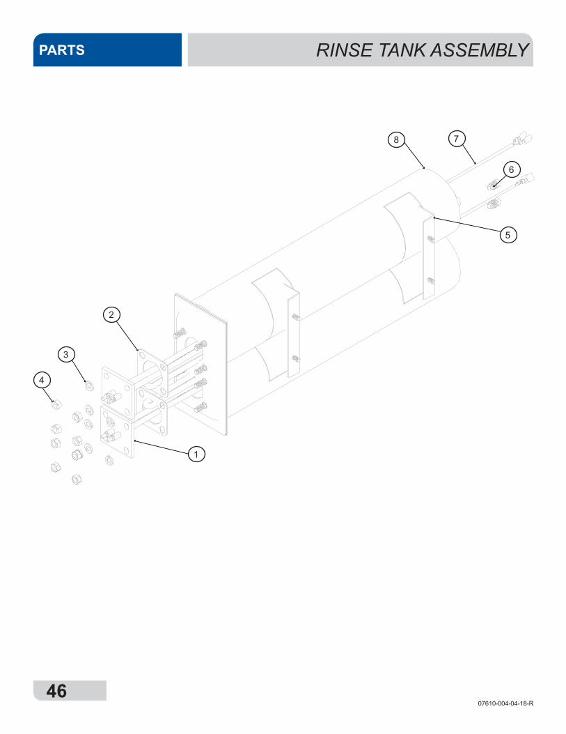
RINSE TANK ASSEMBLYPARTS
8 7
6
5
2
3
4
1
4707610-004-04-18-R
RINSE TANK ASSEMBLY PARTS
ITEM QTY DESCRIPTION PART NUMBER1 2 Booster Heater, 2 kW 04540-003-98-38
1 ** 480 V Unit Booster Heater 04540-004-13-30
2 2 Heater Gasket 05330-011-61-34
1 ** 480 V Heater Gasket 05330-011-47-79
3 8 Lockwasher, Split 5/16" S/S 05311-275-01-00
4 8 Nut, Hex 5/16"-18 S/S 05310-275-01-00
5 1 Booster 05700-004-04-16
1 ** 480 V Booster 05700-004-13-25
6 2 Fitting, 1/4", Brass Nut/Sleeve 05310-924-02-05
7 2 Temperature Probe 06680-002-16-80
8 2 Insulation, Booster Tank Wrap 05700-004-09-57
** Models with 480 V Control Box
4807610-004-04-18-R
WASH PUMP ASSEMBLYPARTSPART NUMBERDESCRIPTIONQTYITEM
05700-004-08-21F-HOSE 1 1/4 X 81105700-004-02-94W-SUMP, AVENGER HT ES1204730-719-18-00CLAMP, REG. RANGE 1-1/16 - 2 HS245304730-003-91-41PUMP,DRAIN AVENGER HT ES1404720-004-20-12ELBOW, 1 HOSE BARB DRAIN2504720-111-39-73HOSE, DRAIN 8"1604720-111-39-73HOSE, DRAIN 3"1704730-719-06-09CLAMP, REG RANGE 13/16- 1 1/2 #165806105-002-16-29MOTOR,PUMP3/4/115/230V/60(JSP1V)1905700-004-01-64F-BRACE KT,MOTOR MOUNT AVG HT ES11004720-004-02-73ELBOW, PUMP TO WASH MANIFOLD11105311-276-01-00LOCKWASHER, 3/821205310-276-01-00NUT, HEX 3/8-16 S/S21305305-276-03-00BOLT, HEX 3/8-16 X 1 LONG S/S21405700-001-22-92BOTTOM WASH DISCHARGE HOSE11505330-400-05-00O-RING, VITON11605700-004-03-73W-SUMP STRAINER11705700-004-04-40W-STAND PIPE, AVENGER118
PARTS LIST
15
12
16
17
11 3
141312
10 98
5
6
7
4
18
4907610-004-04-18-R
WASH PUMP ASSEMBLY PARTS
** Models with 480 V Control Box
3
ITEM QTY DESCRIPTION PART NUMBER
1 1 Hose 1 1/4" x 8" 05700-004-08-21
2 1 Sump 05700-004-02-94
3 2 Clamp, 1 1/16" to 2" 04730-719-18-00
4 1 Drain Pump 04730-003-91-41
5 2 Elbow, Hose Barb Drain 04720-004-20-12
6 1 Drain Hose, 8" 04720-111-39-73
7 1 Drain Hose, 3" 04720-111-39-73
8 5 Clamp, 13/16" to 1 1/2" 04730-719-06-09
91 Wash Pump 06105-004-24-79
1 ** 480 V Wash Pump 06105-004-07-54
10 1 Motor Mount Brace 05700-004-01-64
11 1 Elbow, Pump to Wash Manifold 04720-004-02-73
12 2 Lockwasher, 3/8" 05311-276-01-00
13 2 Nut, Hex 3/8-16 x 1 Long 05310-276-01-00
14 2 Bolt, Hex 3/8-16 x 1 Long 05305-276-03-00
15 1 Bottom Wash Dishcharge Hose 05700-001-22-92
16 1 O-ring, Viton 05330-400-05-00
17 1 Sump Strainer 05700-004-03-73
18 1 Standpipe 05700-004-04-40
NOTE: Items 6 and 7 are the same part made from raw hose material that is cut to order. When ordering, please specify the length that is needed.
5007610-004-04-18-R
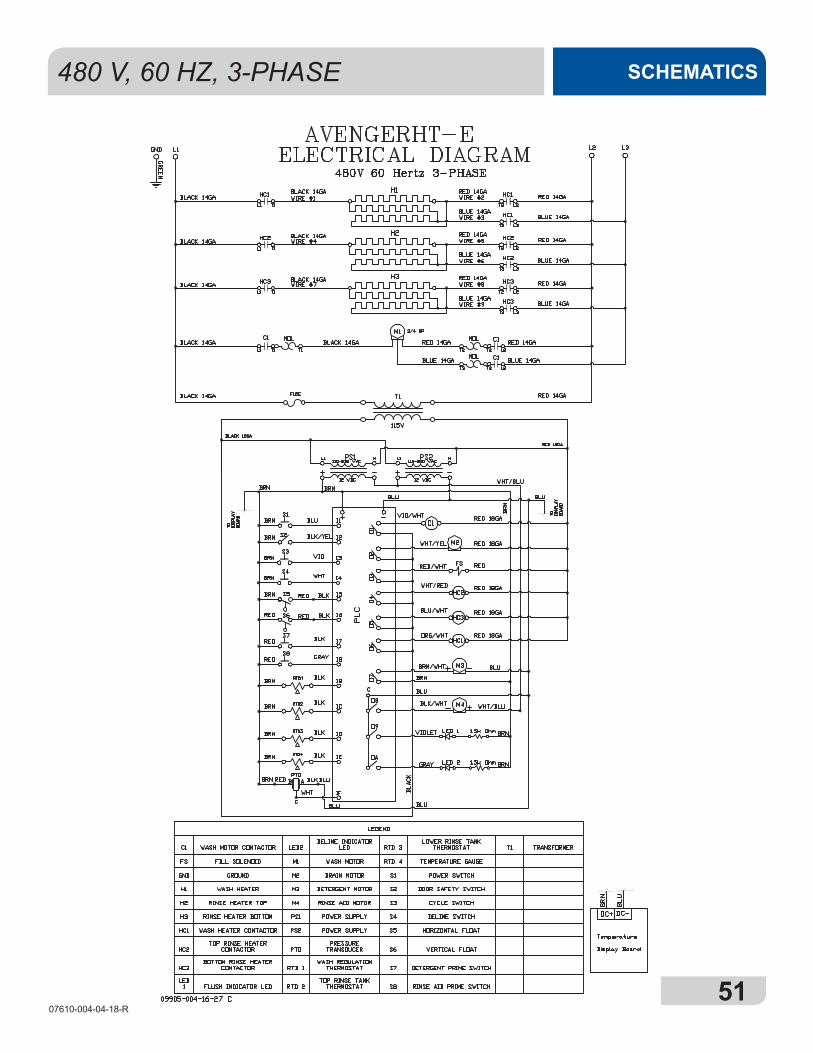
SCHEMATICS
GND GROUND S1 POWER SWITCH
RTD1 WASH REGULATING THRMOSTATH1 WASH HEATER S2 DOOR SAFETY SWITCH
RTD2 TOP RINSE TANK THERMOSTATH2 RINSE HEATER TOP S3 CYCLE SWITCH
RTD3 LOWER RINSE TANK THERMOSTATH3 RINSE HEATER BOTTOM S4 DELIME SWITCH
RTD4 TEMPERATURE GAUGEM1 WASH MOTOR S5 HORIZONTAL FLOAT SWITCH
FS RINSE/FILL SOLENOIDM2 DRAIN MOTOR S6 VERTICAL FLOAT SWITCH
HC1 WASH HEATER CONTACTORM3 DETERGENT MOTOR S7 RINSE AID PRIME SWITCH
HC2 TOP RINSE HEATER CONTACTORM4 RINSE AID MOTOR S8 DETERGENT PRIME SWITCH
HC3 LOWER RINSE HEATER CONTACTORPTD PRESSURE TRANSDUCER PS1 POWER SUPPLY
C1 WASH MOTOR CONTACTORPS2 POWER SUPPLY
LED 1
LED 2
FLUSH INDICATOR LED
DELIME INDICATOR LED
208/230 V, 50/60 HZ, 1-PHASE
5107610-004-04-18-R
SCHEMATICS480 V, 60 HZ, 3-PHASE

Jackson WWS, Inc. • 6209 N. US Hwy 25E • Gray, KY 40734 USA1.888.800.5672 • www.jacksonwws.com
Avenger® HT-E Manual • Rev R • 07610-004-04-18 • Issued: 01-01-14 • Revised: 10-05-16