installation, operation, and maintenance · pdf filereduced pressure principle backflow...
TRANSCRIPT
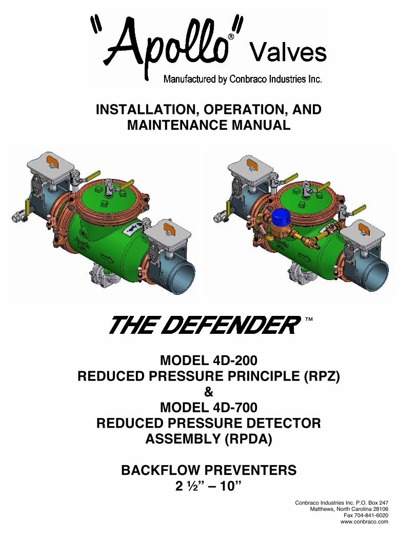
INSTALLATION, OPERATION, AND MAINTENANCE MANUAL
MODEL 4D-200 REDUCED PRESSURE PRINCIPLE (RPZ)
& MODEL 4D-700
REDUCED PRESSURE DETECTOR ASSEMBLY (RPDA)
BACKFLOW PREVENTERS
2 ½” – 10” Conbraco Industries Inc. P.O. Box 247 Matthews, North Carolina 28106 Fax 704-841-6020
www.conbraco.com
™
TABLE OF CONTENTS
Reduced Pressure Principle Backflow Preventer 4D-200 (RP) 2 ½” – 10” Section Page I. Description and Operation …………………………………………………….….2 II. Installation…………………………………………………………………..……....3 III. Trouble Shooting Guide……………………………………………………..….…4 IV. Check Valve Maintenance Instructions 2 ½” – 10” RP & RPDA………..…….5 V. Relief Valve Maintenance Instructions 2 ½” – 10” RP & RPDA……..…….….8 VI. Testing Procedure RP / RPDA..……………………………….………...…11, 12 Reduced Pressure Detector Assembly 4D-700 (RPDA) 2 ½” – 10”
Section Page
I. Description and Operation……………………………………………………….13 II. Installation……...…………………………………………………………………...3 III. Trouble Shooting Guide………………………….………………………………..4
Part Lists
2 ½” – 10” RP & RPDA Check Valves..…………………………..………………6, 7 2 ½” – 10” RP & RPDA Relief Valves.….………..………………….………………9 2 ½” – 10” RP & RPDA By-pass Detector………………………………………….10 Backflow Preventer Test Kits………………………………………………………..14 Miscellaneous Replacement Parts……………………………………………….....14
Repair Kits
2 ½” – 10” RP & RPDA (Check Valves)…………….…………………….…………7 2 ½” – 10” RP & RPDA (Relief Valves)…………………………….………….…….9 2 ½” – 10” RPDA (By-Pass Assembly)……………………………….……….…...10
1
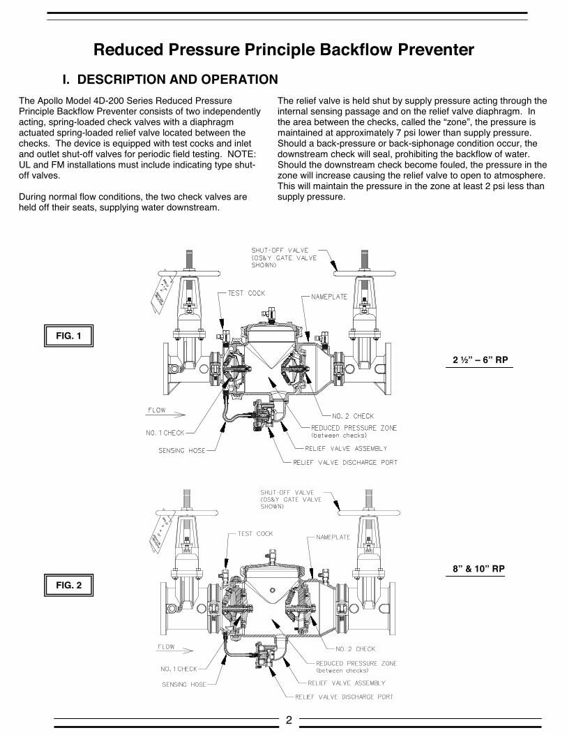
Reduced Pressure Principle Backflow Preventer
I. DESCRIPTION AND OPERATION
2 ½” – 6” RP
The Apollo Model 4D-200 Series Reduced Pressure Principle Backflow Preventer consists of two independently acting, spring-loaded check valves with a diaphragm actuated spring-loaded relief valve located between the checks. The device is equipped with test cocks and inlet and outlet shut-off valves for periodic field testing. NOTE: UL and FM installations must include indicating type shut-off valves. During normal flow conditions, the two check valves are held off their seats, supplying water downstream.
The relief valve is held shut by supply pressure acting through the internal sensing passage and on the relief valve diaphragm. In the area between the checks, called the “zone”, the pressure is maintained at approximately 7 psi lower than supply pressure. Should a back-pressure or back-siphonage condition occur, the downstream check will seal, prohibiting the backflow of water. Should the downstream check become fouled, the pressure in the zone will increase causing the relief valve to open to atmosphere. This will maintain the pressure in the zone at least 2 psi less than supply pressure.
FIG. 1
FIG. 2 8” & 10” RP
2
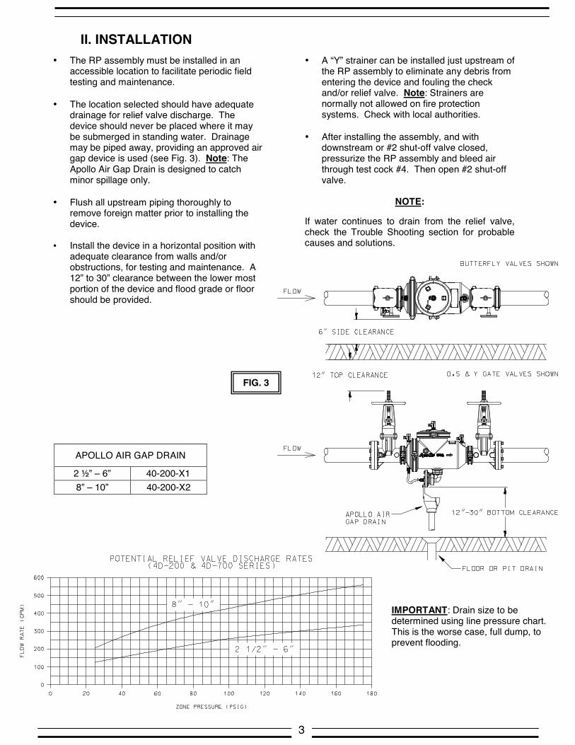
II. INSTALLATION
• A “Y” strainer can be installed just upstream of the RP assembly to eliminate any debris from entering the device and fouling the check and/or relief valve. Note: Strainers are normally not allowed on fire protection systems. Check with local authorities.
• After installing the assembly, and with
downstream or #2 shut-off valve closed, pressurize the RP assembly and bleed air through test cock #4. Then open #2 shut-off valve.
NOTE:
If water continues to drain from the relief valve, check the Trouble Shooting section for probable causes and solutions.
• The RP assembly must be installed in an accessible location to facilitate periodic field testing and maintenance.
• The location selected should have adequate
drainage for relief valve discharge. The device should never be placed where it may be submerged in standing water. Drainage may be piped away, providing an approved air gap device is used (see Fig. 3). Note: The Apollo Air Gap Drain is designed to catch minor spillage only.
• Flush all upstream piping thoroughly to
remove foreign matter prior to installing the device.
• Install the device in a horizontal position with
adequate clearance from walls and/or obstructions, for testing and maintenance. A 12” to 30” clearance between the lower most portion of the device and flood grade or floor should be provided.
3
APOLLO AIR GAP DRAIN
2 ½” – 6” 40-200-X1 8” – 10” 40-200-X2
FIG. 3
IMPORTANT: Drain size to be determined using line pressure chart. This is the worse case, full dump, to prevent flooding.
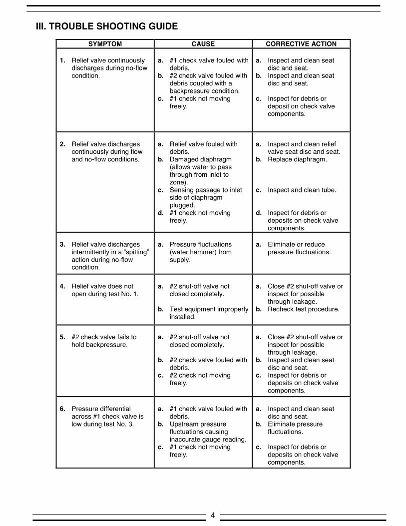
III. TROUBLE SHOOTING GUIDE
SYMPTOM CAUSE CORRECTIVE ACTION
1. Relief valve continuously discharges during no-flow condition.
a. #1 check valve fouled with
debris. b. #2 check valve fouled with
debris coupled with a backpressure condition.
c. #1 check not moving freely.
a. Inspect and clean seat
disc and seat. b. Inspect and clean seat
disc and seat. c. Inspect for debris or
deposit on check valve components.
2. Relief valve discharges
continuously during flow and no-flow conditions.
a. Relief valve fouled with
debris. b. Damaged diaphragm
(allows water to pass through from inlet to zone).
c. Sensing passage to inlet side of diaphragm plugged.
d. #1 check not moving freely.
a. Inspect and clean relief
valve seat disc and seat. b. Replace diaphragm. c. Inspect and clean tube. d. Inspect for debris or
deposits on check valve components.
3. Relief valve discharges
intermittently in a “spitting” action during no-flow condition.
a. Pressure fluctuations
(water hammer) from supply.
a. Eliminate or reduce
pressure fluctuations.
4. Relief valve does not
open during test No. 1.
a. #2 shut-off valve not
closed completely. b. Test equipment improperly
installed.
a. Close #2 shut-off valve or
inspect for possible through leakage.
b. Recheck test procedure.
5. #2 check valve fails to
hold backpressure.
a. #2 shut-off valve not
closed completely. b. #2 check valve fouled with
debris. c. #2 check not moving
freely.
a. Close #2 shut-off valve or
inspect for possible through leakage.
b. Inspect and clean seat disc and seat.
c. Inspect for debris or deposits on check valve components.
6. Pressure differential
across #1 check valve is low during test No. 3.
a. #1 check valve fouled with
debris. b. Upstream pressure
fluctuations causing inaccurate gauge reading.
c. #1 check not moving freely.
a. Inspect and clean seat
disc and seat. b. Eliminate pressure
fluctuations. c. Inspect for debris or
deposits on check valve components.
4

5
FIG. 5 FIG. 4
If the valve experiences inadequate test readings, often it is a sign of foreign particles or debris collected on the seat disc of one of the check valves. The check assembly must be removed for inspection. Clean or replace the seat disc as necessary. Also inspect the sealing lip on the seat for damage. A deep scratch or knick can affect the check readings. CHECK ASSEMBLY REMOVAL See Figure 4: Make sure there is no pressure on the valve by opening the test cock on the lid. Remove the upper groove connection coupling by removing the bolts and nuts. Slide away the coupling clamps and remove the rubber gasket. Lift off the lid. The valve should be drained of water (the relief valve will open releasing the water in the zone when the source pressure is off). Either check valve assembly can be removed without disturbing the other. Remove the nuts from the studs that are screwed into the body. The nuts can be removed using standard tools (socket wrench and extension shown). 2.5”-4” sizes: Remove the four (4) lock hex nuts holding each check assembly using ½” hex socket wrench. Lift out the check assembly. 6” size: Remove the six (6) lock hex nuts holding each check assembly using 9/16” hex socket wrench. Lift out the check assembly. 8” & 10” sizes: Remove the six (6) hex nuts holding each check assembly using 3/4” hex socket. Lift out the check assembly.
SEAT DISC INSPECTION OR REPLACEMENT See Figure 5: To inspect or replace the seat disc remove the long socket head cap screw that holds the spring hub assembly in place. This will release the load from the spring and allow the disc holder to slide away from the front of the assembly. 2.5”-4” sizes: Remove the cap screw with a 3/16” hex drive (Allen wrench). With the disc holder loose, remove the three (3) screws that hold the disc plate with a 5/32” hex drive (Allen wrench). Remove the rubber disc and clean or replace. 6” size: Remove the cap screw with a 5/16” hex drive (Allen wrench). With the disc holder loose, remove the four (4) screws that hold the disc plate with a 7/32” hex drive (Allen wrench). Remove the rubber disc and clean or replace. 8” & 10” sizes: Remove the cap screw with a ½” hex drive (Allen wrench). With the disc holder loose, remove the six (6) screws that hold the disc plate. Use a 7/32” hex drive (Allen wrench). Remove the rubber disc and clean or replace.
RE-ASSEMBLING THE CHECK ASSEMBLY: Install the screws firmly. Use of a medium strength thread locking Loctite® is recommended on all threads. Re-install the cap screw that holds the assembly together and applies the spring load. This screw is designed to be screwed in all the way until it runs out of threads. When re-installing the checks, make certain the o-ring is seated in its groove. Use a non-toxic grease to aid retention of the o-ring in its groove. Tighten the hex nuts to hold the check assembly in place. These should be tightened firmly and evenly for the o-ring to seal.
IV. CHECK VALVE MAINTENANCE
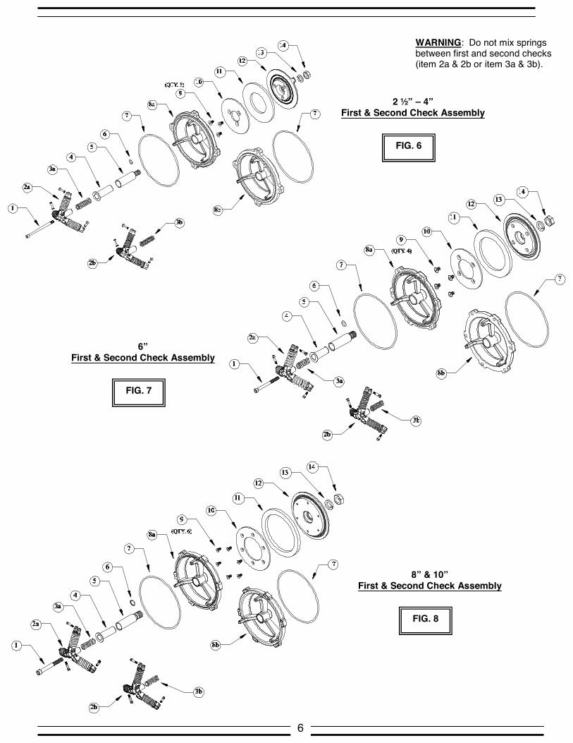
2 ½” – 4” First & Second Check Assembly
FIG. 6
6” First & Second Check Assembly
FIG. 7
8” & 10” First & Second Check Assembly
FIG. 8
6
WARNING: Do not mix springs between first and second checks (item 2a & 2b or item 3a & 3b).
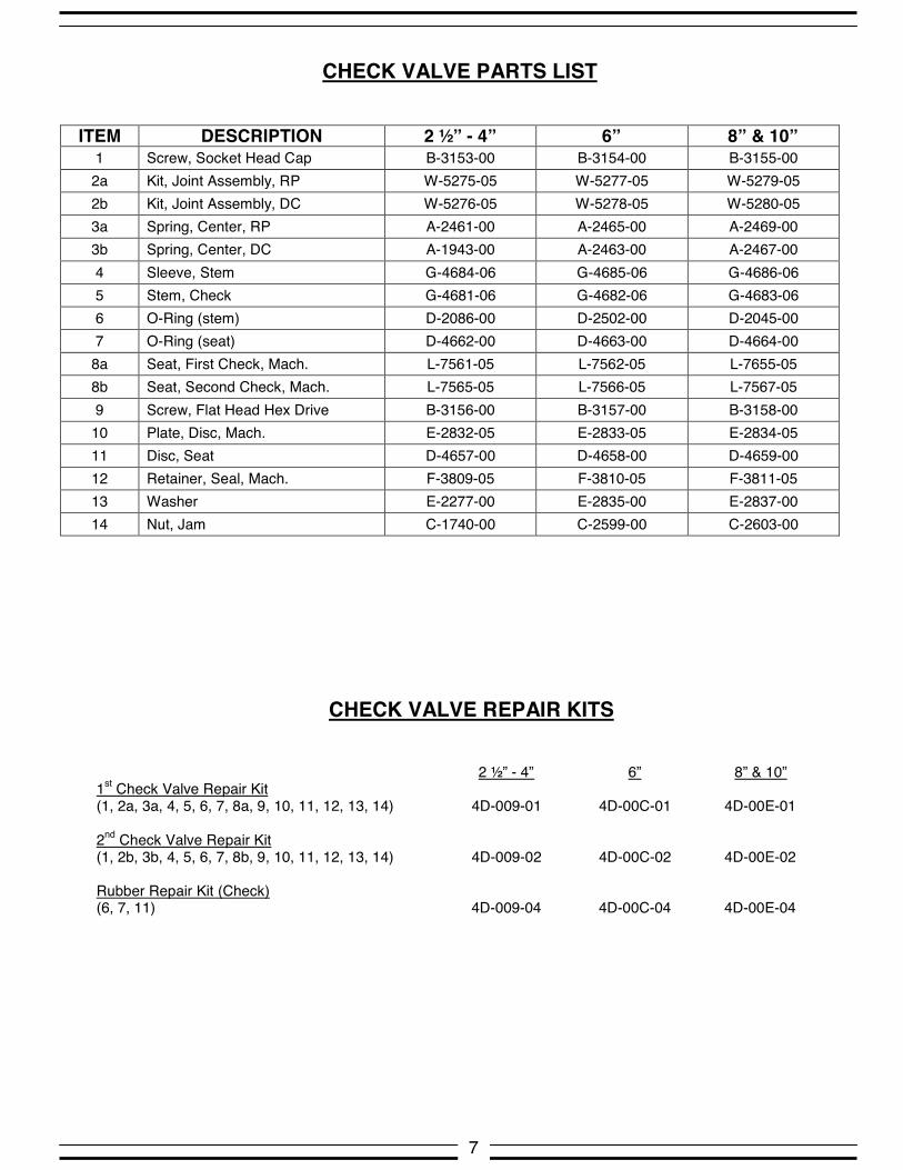
ITEM DESCRIPTION 2 ½” - 4” 6” 8” & 10” 1 Screw, Socket Head Cap B-3153-00 B-3154-00 B-3155-00 2a Kit, Joint Assembly, RP W-5275-05 W-5277-05 W-5279-05 2b Kit, Joint Assembly, DC W-5276-05 W-5278-05 W-5280-05 3a Spring, Center, RP A-2461-00 A-2465-00 A-2469-00 3b Spring, Center, DC A-1943-00 A-2463-00 A-2467-00 4 Sleeve, Stem G-4684-06 G-4685-06 G-4686-06 5 Stem, Check G-4681-06 G-4682-06 G-4683-06 6 O-Ring (stem) D-2086-00 D-2502-00 D-2045-00 7 O-Ring (seat) D-4662-00 D-4663-00 D-4664-00 8a Seat, First Check, Mach. L-7561-05 L-7562-05 L-7655-05 8b Seat, Second Check, Mach. L-7565-05 L-7566-05 L-7567-05 9 Screw, Flat Head Hex Drive B-3156-00 B-3157-00 B-3158-00 10 Plate, Disc, Mach. E-2832-05 E-2833-05 E-2834-05 11 Disc, Seat D-4657-00 D-4658-00 D-4659-00 12 Retainer, Seal, Mach. F-3809-05 F-3810-05 F-3811-05 13 Washer E-2277-00 E-2835-00 E-2837-00 14 Nut, Jam C-1740-00 C-2599-00 C-2603-00
CHECK VALVE PARTS LIST
7
2 ½” - 4” 6” 8” & 10” 1st Check Valve Repair Kit (1, 2a, 3a, 4, 5, 6, 7, 8a, 9, 10, 11, 12, 13, 14) 4D-009-01 4D-00C-01 4D-00E-01 2nd Check Valve Repair Kit (1, 2b, 3b, 4, 5, 6, 7, 8b, 9, 10, 11, 12, 13, 14) 4D-009-02 4D-00C-02 4D-00E-02 Rubber Repair Kit (Check) (6, 7, 11) 4D-009-04 4D-00C-04 4D-00E-04
CHECK VALVE REPAIR KITS
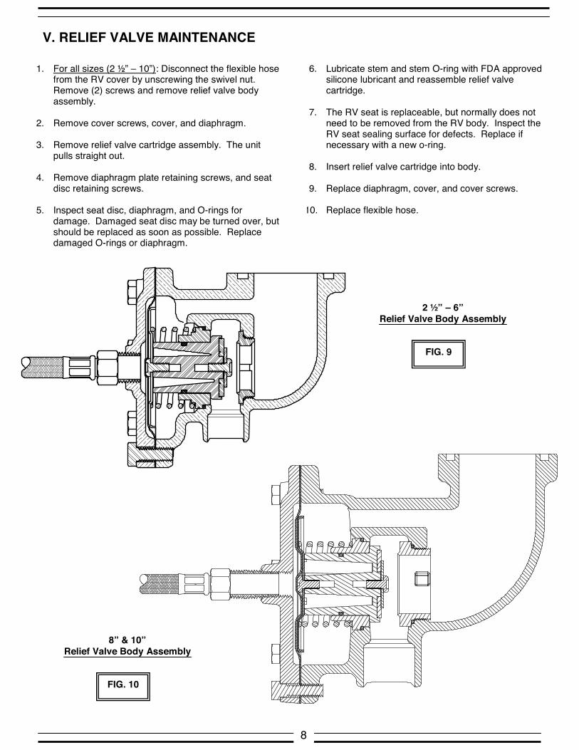
V. RELIEF VALVE MAINTENANCE
1. For all sizes (2 ½” – 10”): Disconnect the flexible hose from the RV cover by unscrewing the swivel nut. Remove (2) screws and remove relief valve body assembly.
2. Remove cover screws, cover, and diaphragm. 3. Remove relief valve cartridge assembly. The unit
pulls straight out. 4. Remove diaphragm plate retaining screws, and seat
disc retaining screws. 5. Inspect seat disc, diaphragm, and O-rings for
damage. Damaged seat disc may be turned over, but should be replaced as soon as possible. Replace damaged O-rings or diaphragm.
6. Lubricate stem and stem O-ring with FDA approved silicone lubricant and reassemble relief valve cartridge.
7. The RV seat is replaceable, but normally does not
need to be removed from the RV body. Inspect the RV seat sealing surface for defects. Replace if necessary with a new o-ring.
8. Insert relief valve cartridge into body. 9. Replace diaphragm, cover, and cover screws.
10. Replace flexible hose.
8
FIG. 9
FIG. 10
2 ½” – 6” Relief Valve Body Assembly
8” & 10” Relief Valve Body Assembly

2 ½” – 6” Relief Valve Body Assembly
RELIEF VALVE PARTS LIST
ITEM DESCRIPTION 2 ½” - 6" 8” & 10” 1 Screw, Hex Head Cap Screw B-1792-00 B-1796-00 2 Cover, Relief Valve, Mach. Q-6768-05 Q-6770-05 3 Diaphragm, 4D Series D-4696-00 D-2564-00 4 Sub-Assembly, Relief Valve, 4D Series W-5256-05 W-5301-05 5 O-Ring D-2512-00 D-2565-00 6 Seat, Relief Valve L-4867-00 L-7616-05 7 O-Ring D-2274-00 D-2568-00 8 Screw, Hex Head Cap Screw B-2550-00 B-2348-00 9 Body, Relief Valve, Mach. Q-6767-05 Q-6769-05 10 O-Ring D-4009-00 D-2571-00 11 Screw, Pan Head Machine Screw B-1753-00 B-1753-00 12 Plate, Diaphragm, 40/4S/4D Series D-2516-00 E-2201-00 13 Spring, Relief Valve, 4D Series A-2477-00 A-1742-00 14 Bushing, Relief Valve, 4D Series I-8757-15 I-8797-15 15 O-Ring D-2513-00 D-2562-00 16 Stem, Relief Valve, 40/4S/4D Series G-3213-00 G-3240-00 17 Washer D-2499-00 E-2200-00 18 Disc Seat, Relief Valve, 40/4S/4D Series D-2514-00 D-2563-00
FIG. 11
8” & 10” Relief Valve Body Assembly
FIG. 12
9
RELIEF VALVE REPAIR KITS 2 ½” – 6” 8” & 10” Relief Valve Repair Kit (3, 10, 11, 12, 13, 14, 15, 16, 17, 18) 4D-009-05 4D-00E-05 Relief Valve Rubber Repair Kit 4D-009-06 4D-00E-06 (3, 5, 7, 10, 15, 18)

Front View
10
DETECTOR ASSEMBLY PARTS LIST
Top View
FIG. 14
FIG. 13
FIG. 15
SIZE METER OPTION
BY-PASS LINE REPLACEMENT KIT
GALLONS 4D-709-BPE CU FEET 4D-709-BPC 2 ½” – 4”
LESS METER 4D-709-BPG GALLONS 4D-70C-BPE CU FEET 4D-70C-BPC 6”
LESS METER 4D-70C-BPG GALLONS 4D-70E-BPE CU FEET 4D-70E-BPC 8” – 10”
LESS METER 4D-70E-BPG
The RPDA by-pass line contains brass. This material meets the requirement of the EPA Safe Drinking Water Act. WARNING: (Required by California) This product contains a chemical known to the state of California to cause Cancer, Birth Defects, and other reproductive harm.
ITEM DESCRIPTION 2 ½” - 4" 6” 8” & 10” 1 Nipple K-3982-00 K-3982-00 K-3982-00 2 Elbow, 90° K-3959-00 K-3959-00 K-3959-00 3 Ball Valve (with test port) 7B-803-01 7B-803-01 7B-803-01 4 Test Cock 78-257-01 78-257-01 78-257-01 5 Nipple K-3460-00 K-3460-00 K-3460-00 6 Elbow, 45° K-3963-00 K-3963-00 K-3963-00 7 Nut, Meter C-1844-05 C-1844-05 C-1844-05 8 Meter Connector K-4444-06 K-4444-06 K-4456-06 9 Gasket, Meter D-2610-00 D-2610-00 D-2610-00
10a Meter, Cubic Feet Per Minute W-7062-00 W-7062-00 W-7062-00 10b Meter, Gallons per Minute W-7094-00 W-7094-00 W-7094-00 11 Meter Connector K-3960-06 K-3960-06 K-4456-06 12 Sub-Assy, By-Pass Check Valve W-5287-05 W-5287-05 W-5287-05 13 By-Pass Body Q-6783-05 Q-6783-05 Q-6783-05 14 O-Ring D-3885-00 D-3885-00 D-3885-00 15 Check Valve Insert F-3228-00 F-3228-00 F-3228-00 16 O-Ring D-3589-00 D-3589-00 D-3589-00 17 Cap F-3818-05 F-3818-05 F-3818-05 18 Nipple K-3980-00 K-3980-00 K-4457-00 19 Ball Valve (without test port) 7B-803-31 7B-803-31 7B-803-31 20 Bushing N/A K-3503-00 K-3503-00 21 Ball Valve 78-483-01 78-484-01 78-484-01 22 Tee K-3571-00 K-3511-00 K-3511-00 23 Nipple K-3771-00 K-3772-00 K-4458-00

VI. TESTING PROCEDURES
11
TEST NO. 1 PURPOSE: To test operation of the pressure differential relief valve. REQUIREMENT: The pressure differential relief valve must operate to maintain the zone between the two check valves at a minimum of 2 psi less than the supply pressure. PROCEDURE: 1. Open test cock #4 to establish flow through the RP. Flush
test cocks in the following order taking care not to dump the relief valve. Open and close test cock #1. SLOWLY open and close test cock #2. Open and close test cock #3. Close test cock #4. Install appropriate adapters in all test cocks.
2. Connect the “high” side hose to test cock #2. Connect the “low” side hose to test cock #3.
3. Fully open the test kit by-pass valve. 4. Slowly open test cock #2. Bleed the high side through the
by-pass hose by opening the high side valve. Close the high side valve.
5. Slowly open test cock #3. Bleed the low side through the by-pass hose by opening the low side valve. After the pointer reaches the upper end of the scale, close the by-pass and low side valves.
6. Close the #2 shut-off valve and observe the pressure drop across Check Valve #1. Should the pressure drop until the relief valve discharges continuously, Check Valve #1 is leaking and must be repaired before continuing.
7. Open the high side valve. 8. Open the low side valve no more than one-quarter (1/4)
turn. 9. Watch the gauge drop slowly to the relief valve opening
point and record the reading (if the pressure differential does not drop to the relief valve opening point, close the high and low side valves and go to step 11).
10. Close the high and low side valves and go to Test 2. 11. No. 2 shut-off valve may be leaking. Reopen and close
No. 2 shut-off valve to attempt a better shut-off. Repeat steps 7 through 9. If the relief valve does not open, a by-pass hose is required.
12. Attach a hose to test cock #1. Bleed hose by opening test cock #1. Close test cock #1.
13. Connect the hose from test cock #1 to test cock #4. 14. Open test cock #1 to pressurize the hose. 15. SLOWLY open test cock #4. Repeat steps 7 through 9.
If the relief valve does not open, the leaky No. 2 shut-off valve must be repaired.
TEST NO. 2 PURPOSE: To test check valve No. 2 for tightness against backpressure. (Note: This test is to be repeated for detector line check using test cocks on detector line.)
REQUIREMENT: Check valve No. 2 shall permit no through leakage in a direction reverse to normal flow under conditions of a backpressure. PROCEDURE:
BY-PASS HOSE NOT USED IN TEST 1 1. Bleed by-pass hose by opening the high side and by-pass
valves. Close the by-pass valve. 2. Attach by-pass hose to test cock #4. Open test cock #4. 3. Loosen the low side hose at test cock #3 to re-establish
the normal reduced pressure within the “zone”. Retighten the low side hose at test cock #3.
4. Open the by-pass valve. 5. If the differential pressure stabilizes above the relief valve
opening point, Check Valve #2 is recorded as “tight” (Proceed to Test No. 3). If the reading falls to the relief valve opening point, Check Valve #2 is recorded as “leaking” and Test No. 3 cannot be completed.
BY-PASS HOSE USED IN TEST 1 1. Leave the by-pass hose connected between test cock #1
and #4. 2. Leave test cocks #1 and #4 open. 3. Open the low side and by-pass valves allowing the pointer
to reach the upper part of the scale. Close the low side and the by-pass valves.
4. If the differential pressure stabilizes above the relief valve opening point, Check Valve #2 is recorded as “tight” (Proceed to Test No. 3). If the reading falls to the relief valve opening point, Check Valve #2 is recorded as “leaking” and Test No. 3 cannot be completed.
TEST NO. 3 PURPOSE: To test the static differential pressure across Check Valve No. 1. REQUIREMENT: The static differential pressure across Check Valve No. 1 must be a minimum of 3 psi greater than the opening differential pressure of the relief valve as recorded in Test No. 1. PROCEDURE:
BY-PASS HOSE NOT USED IN TESTS 1 & 2 1. Close the high side and by-pass valves. Close test cock
#4 and disconnect the by-pass hose. 2. Open the low side and by-pass valves allowing the pointer
to reach the upper end of the scale. Close the low and by-pass valves.
3. Allow the gauge reading to stabilize. Record this reading as the static pressure drop across Check Valve #1.
BY-PASS HOSE USED IN TESTS 1 & 2 1. Open the low side and by-pass valves allowing the pointer
to reach the upper end of the scale. Close the low side and by-pass valves.
2. Allow the gauge reading to stabilize. Record this reading as the static pressure drop across Check Valve #1.
WRAP UP: Close all test cocks. Open No. 2 shut-off valve. Remove all test equipment. Drain test kit.

APOLLO VALVES REDUCED PRESSURE DETECTOR ASSEMBLY MODEL 4D-700 (By-Pass Check)
FIG. 16
FIG. 17
APOLLO VALVES REDUCED PRESSURE BACKFLOW PREVENTER MODEL 4D-200 & 4D-700 (Mainline Valve)
12
LEGEND
TEST KIT VALVE TC TEST COCK

Reduced Pressure Detector Assembly I. DESCRIPTION AND OPERATION
13
The Apollo Model 4D-700 Series Reduced Pressure Detector Assembly Backflow Preventer consists of two independently acting, spring-loaded check valves with a diaphragm actuated spring-loaded relief valve located between the checks. The device is equipped with test cocks and inlet and outlet shut-off valves for periodic field testing. NOTE: UL and FM installations must include indicating type shut-off valves. During normal flow conditions, the two check valves are held off their seats, supplying water downstream.
The relief valve is held shut by supply pressure acting through the internal sensing passage and on the relief valve diaphragm. In the area between the checks, called the “zone”, the pressure is maintained at approximately 7 psi lower than supply pressure. Should a back-pressure or back-siphonage condition occur, the downstream check will seal, prohibiting the backflow of water. Should the downstream check become fouled, the pressure in the zone will increase causing the relief valve to open to atmosphere. This will maintain the pressure in the zone at least 2 psi less than supply pressure.
FIG. 18
FIG. 19
2 ½” – 6” RPDA
8” & 10” RPDA

BACKFLOW PREVENTER TEST KITS
DESCRIPTION The Apollo Valves/Conbraco Backflow Preventer Test Kits are compact, lightweight, and portable testing devices. They come equipped with a gauge, hoses, and all required adapter fittings. These test kits also feature a line pressure gauge in addition to the differential pressure gauge, a thermoplastic gauge body, adjustable nylon strap, laminated test procedures and a molded plastic carrying case with foam inserts.
DIFFERENTIAL PRESSURE GAUGE TEST KIT 40-200-TKU This is a three valve test kit used for testing all DCV, RPZ, PVB & SVB backflow preventers. The gauge is a differential pressure type with a dual scale of 0-15 psid/0-100 kPa differential pressure range with a +/- 0.2 psid accuracy (descending). 40-200-TK5U This is a five valve test kit used for testing all DCV, RPZ, PVB & SVB backflow preventers. The five valve test kit is similar to the three valve test kit except it has two additional soft-seated needle valves and a bleed tube that make it possible to bleed lines without disconnecting hoses. MODEL APPLICATION WT./100 (lbs) 40-200-TKU ALL DCV, RPZ, PVB & SVB 780 40-200-TK5U ALL DCV, RPZ, PVB & SVB 650
14
Miscellaneous Replacement Parts
Part Description 2 ½” 3” 4” 6” 8” 10”
Inlet Body Q-6751-19 Q-6752-19 Q-6753-19 Q-6754-19 Q-6755-19 Q-6756-19
Outlet Body Q-6757-19 Q-6758-19 Q-6759-19 Q-6760-19 Q-6761-19 Q-6762-19
Lid Q-6763-19 Q-6763-19 Q-6763-19 Q-6764-19 Q-6765-19 Q-6765-19
Lid Coupling Set W-5241-00 W-5241-00 W-5241-00 W-5242-00 W-5243-00 W-5243-00
Pipe Line Coupling Set W-5237-00 W-5238-00 W-5239-00 W-5240-00 W-5241-00 W-5242-00
Test Cock (Male x Female) 78-483-01 78-483-01 78-483-01 78-484-01 78-484-01 78-484-01
Test Cock (Female x Female) 76-103-01 76-103-01 76-103-01 76-104-01 76-104-01 76-104-01
Flexible Hose W-5250-00 W-5250-00 W-5250-00 W-5250-00 W-5250-00 W-5250-00
Butterfly Valve - Grooved W-5244-00 W-5245-00 W-5246-00 W-5247-00 W-5248-00 W-5249-00
Gate Valve (NRS) - Flanged W-5310-00 W-5311-00 W-5312-00 W-5313-00 W-5314-00 W-5315-00
Gate Valve (OS&Y) - Grooved W-5282-00 W-5283-00 W-5284-00 W-5285-00 W-5286-00 W-5321-00
Gate Valve (OS&Y) - Flanged W-4733-00 W-4734-00 W-4735-00 W-4736-00 W-4737-00 W-4738-00
Hand Wheel - (NRS) H-2783-00 H-2785-00 H-2785-00 H-2787-00 H-2789-00 H-2791-00
Hand Wheel - (OS&Y) H-2784-00 H-2786-00 H-2786-00 H-2788-00 H-2790-00 H-2792-00