installation, operation and maintenance...
TRANSCRIPT

MHP Precleaner
Installation, Operation and Maintenance Manual
www.flexco.comwww.flexco.com

MHP Precleaner
Serial Number: _____________________________________________________________
Purchase Date: ______________________________________________________________
Purchased From: ____________________________________________________________
Installation Date: ____________________________________________________________
Serial number information can be found on the Serial Number Label
included in the Information Packet found in the cleaner carton.
This information will be helpful for any future inquiries or questions
about belt cleaner replacement parts, specifications or troubleshooting.

1
Table of Contents
Section 1 – Important Information ...........................................................................................................2 1.1 General Introduction ..................................................................................................................................2 1.2 User Benefits ................................................................................................................................................2 1.3 Service Option .............................................................................................................................................2
Section 2 – Safety Considerations and Precautions ..................................................................................3 2.1 Stationary Conveyors ..................................................................................................................................3 2.2 Operating Conveyors ..................................................................................................................................3
Section 3 – Pre-Installation Checks and Options ......................................................................................4 3.1 Checklist .......................................................................................................................................................4 3.2 Cleaner Location Adjustments ..................................................................................................................5 3.3 Optional Installation Accessories ..............................................................................................................6
Section 4 – Installation Instructions..........................................................................................................7
Section 5 – Pre-Operation Checklist and Testing....................................................................................11 5.1 Pre-Op Checklist .......................................................................................................................................11 5.2 Test Run the Conveyor .............................................................................................................................11
Section 6 – Maintenance ..........................................................................................................................12 6.1 New Installation Inspection .....................................................................................................................12 6.2 Routine Visual Inspection ........................................................................................................................12 6.3 Routine Physical Inspection .....................................................................................................................12 6.4 Blade Replacement Instructions ..............................................................................................................13 6.5 Maintenance Log .......................................................................................................................................15 6.6 Cleaner Maintenance Checklist ...............................................................................................................16
Section 7 – Troubleshooting ....................................................................................................................17
Section 8 – Specs and CAD Drawings......................................................................................................18 8.1 Specifications and Guidelines ..................................................................................................................18 8.2 CAD Drawings...........................................................................................................................................20
Section 9 – Replacement Parts .................................................................................................................22 9.1 Replacement Parts List ..............................................................................................................................22 Section 10 – Other Flexco Conveyor Products ........................................................................................23

2 MHP Precleaner
1.1 General IntroductionSection 1 – Important Information
We at Flexco are very pleased that you have selected an MHP Precleaner for your conveyor system.
This manual will help you to understand the operation of this product and assist you in making it work up to its maximum efficiency over its lifetime of service.
It is essential for safe and efficient operation that the information and guidelines presented be properly understood and implemented. This manual will provide safety precautions, installation instructions, maintenance procedures and troubleshooting tips.
If, however, you have any questions or problems that are not covered, please visit our web site or contact our Customer Service Department:
Customer Service: +65-6484-1533
Visit www.flexco.com for other Flexco locations and products.
Please read this manual thoroughly and pass it on to any others who will be directly responsible for installation, operation and maintenance of this cleaner. While we have tried to make the installation and service tasks as easy and simple as possible, it does however require correct installation and regular inspections and adjustments to maintain top working condition.
1.2 User Benefits Correct installation and regular maintenance will provide the following benefits for your operation: • Reduced conveyor downtime • Reduced man-hour labor • Lower maintenance budget costs • Increased service life for the belt cleaner and other conveyor components
1.3 Service Option The MHP Precleaner is designed to be easily installed and serviced by your on-site personnel. However, if
you would prefer complete turn-key factory service, please contact your local Flexco Field Representative.

3
Section 2 – Safety Considerations and Precautions
Before installing and operating the MHP Precleaner, it is important to review and understand the following safety information.
There are set-up, maintenance and operational activities involving both stationary and operating conveyors. Each case has a safety protocol.
2.1 Stationary ConveyorsThe following activities are performed on stationary conveyors:
• Installation • Blade replacement • Repairs• Tension adjustments • Cleaning
DANGER
DANGER
WARNING
WARNING
WARNING
!
!
!
!
!
It is imperative that OSHA/MSHA Lockout/Tagout (LOTO) regulations, 29 CFR 1910.147, be followed before undertaking the preceding activities. Failure to use LOTO exposes workers to uncontrolled behavior of the belt cleaner caused by movement of the conveyor belt. Severe injury or death can result.
Before working:• Lockout/Tagout the conveyor power source• Disengage any takeups• Clear the conveyor belt or clamp securely in place
Use Personal Protective Equipment (PPE):• Safety eyewear• Hardhats• Safety footwear
Close quarters, springs and heavy components create a worksite that compromises a worker’s eyes, feet and skull.
PPE must be worn to control the foreseeable hazards associated with conveyor belt cleaners. Serious injuries can be avoided.
2.2 Operating ConveyorsThere are two routine tasks that must be performed while the conveyor is running:
• Inspection of the cleaning performance • Dynamic troubleshooting
Every belt cleaner is an in-running nip hazard. Never touch or prod an operating cleaner. Cleaner hazards cause instantaneous amputation and entrapment.
Never adjust anything on an operating cleaner. Unforseeable belt projections and tears can catch on cleaners and cause violent movements of the cleaner structure. Flailing hardware can cause serious injury or death.
Belt cleaners can become projectile hazards. Stay as far from the cleaner as practical and use safety eyewear and headgear. Missiles can inflict serious injury.

4 MHP Precleaner
3.1 ChecklistSection 3 – Pre-Installation Checks and Options
• Check that the cleaner size is correct for the beltline width
• Check the belt cleaner carton and make sure all the parts are included
• Review the “Tools Needed” list on the top of the installation instructions
• Check the conveyor site:
- Will the cleaner be installed on a chute
- Are there obstructions that may require cleaner location adjustments (see 3.2 – Cleaner Location Adjustments)
- Is the install on an open head pulley requiring mounting structure (see 3.3 – Optional Installation Accessories)

5
In certain applications it is necessary to modify the location of the precleaner pole due to permanent obstacles that obstruct the desired location. Relocating the pole location can be done easily and does not hinder the performance of the cleaner as long as the “C” dimension is maintained.
NOTE: In the following example we will be lowering the pole location in the “Y” direction, but the same method could also be applied in the “X” direction.
Conveyor situation:
Pulley Diameter: 300mm (12") X = 155mm (6 1/8") Y = 140mm (5 1/2") C = 210mm (8 1/4")
1. Determine the given location dimensions and define the change needed. After laying out the given X & Y dimensions, determine the distance of the modification required for adequate clearance of the pole and tensioning system. (In the example we decide to lower the pole 50mm (2") to clear the support structure).
2. Write down known dimensions. We can now determine two of the three required dimensions which will
allow us to find the third. We know we cannot alter the “C” dimension, so this will remain the same. Also we are required to lower the unit in the “Y” dimension 50mm (2"), so we add 50mm (2") to the given “Y” dimension.
X = ?" Y = 140mm + 50mm = 190mm (5 1/2 + 2 = 7 1/2") C = 210mm (8 1/4")
3. Determine final dimension. On a flat vertical surface, using a level, draw one horizontal line and one vertical line, creating a right triangle (Fig 3a). Measure down from the intersection the determined “Y” dimension and mark (Fig 3b). With the tape measure starting at the modified “Y” mark, swing the tape across the “X” line and mark at the “C” dimension where it crosses the “X” line (Fig 3c). Measure from the intersection to the “C” intersection and this will be your new “X” dimension (Fig. 3d).
X = 89mm (3 1/2") Y = 190mm (7 1/2") C = 210mm (8 1/4")
3.2 Cleaner Location AdjustmentsSection 3 – Pre-Installation Checks and Options
300mm 12"
X
CY
Fig. 3a Fig. 3b Fig. 3c Fig. 3dmark
This distance is new “X” dimension
C (210mm)(8 1/4")
Y (190mm)(7 1/2")
89mm (3 1/2")

6 MHP Precleaner
Section 3 - Pre-Installation Checks and Options
3.3 Optional Installation Accessories
Versatile, adjustable brackets and plates that can be mounted on the conveyor structure so precleaners and secondary cleaners can be easily and quickly bolted into place.
75830Optional Mounting Bar Kit(with bolts, nuts and washers)• For mounting precleaners on
open head pulleys.• Weld on both sides of pulley
and bolt on steel plates.• 38 x 406 mm (1-1/2" x 16")
with four 16 mm (5/8-11) tapped holes
76537Mounting Plate Kit (incl. 2 plates)• For use with Mounting Bars to
mount cleaners on open head pulleys.
• 400 x 800 mm (16" x 32") with four 16 mm (5/8") holes
*Hardware IncludedLead time: 1 working day
Provides 750 mm (30") of extended pole length.Lead time: 1 working day
Optional Mounting Kits (incl. 2 brackets/bars)
DescriptionOrdering Number
Item Code
Wt. Kg.
Optional Mounting Bar Kit * MMBK 75830 8.8Mounting Plate Kit (incl. 2 plates) MMPK 76537 63.5
Pole Extender Kit (incl. 2 pole extenders)
DescriptionOrdering Number
Item Code
Wt. Kg.
Pole Extender Kit MAPEK 76024 9.9

7
Section 4 – Installation Instructions
Physically lock out and tag the conveyor at the power source before you begin cleaner installation.
1. Find the X, Y & C specifications. Measure the pulley diameter (including the belt and the lagging) (Fig. 1).
Pulley Diameter ______"; X=______"; Y=______"; C=______".
(Adjustments can be made to the X & Y coordinates to move away from obstacles as long as the C dimension remains constant.)
CAUTION: Components may be heavy. Use safety-approved lifting procedures.
Fig. 1
X & Y Chart for Pole LocationPulley Diameter (including belt and lagging) X Y C
500 250 365 442525 263 365 450550 275 365 457575 288 365 465600 300 365 472625 313 365 480650 325 365 489675 338 365 497700 350 365 506725 363 365 514750 375 365 523775 388 365 532800 400 365 542825 413 365 551850 425 365 560875 438 365 570900 450 365 579925 463 365 589950 475 365 599975 488 365 609
1000 500 365 6191025 513 365 6291050 525 365 6391075 538 365 6501100 550 365 660
X & Y Chart for Pole LocationPulley Diameter (including belt and lagging) X Y C
1125 563 365 6711150 575 365 6811175 588 365 6921200 600 365 7021225 613 365 7141250 628 365 7271275 641 365 7381300 657 365 7521325 672 365 7651350 685 365 7761375 700 365 7901400 713 365 8011425 728 365 8151450 741 365 8261475 757 365 8401500 769 365 8511525 782 365 8631550 797 365 8771575 810 365 8881600 826 365 9031625 838 365 9141650 850 365 9251675 866 365 9401700 879 365 9511725 891 365 963
X & Y Chart for Pole LocationPulley Diameter (including belt and lagging) X Y C
1750 906 365 9771775 919 365 9891800 932 365 10011825 947 365 10151850 960 365 10271875 972 365 10391900 985 365 10501925 1000 365 10641950 1013 365 10771975 1026 365 10892000 1038 365 11002025 1053 365 11142050 1066 365 11272075 1079 365 11392100 1090 365 1150
4.1 MHP Precleaner
Tools Needed: • Tape Measure• Wrenches or Crescent Wrenches: (2)
19mm (3/4"), (2) 38mm (1-1/2"), (1) 24mm (15/16"), and (1) 16mm (5/8")
• Level• Marking pen or soapstone• C-clamps for AWT only
MegaShear™ Blade
Center Pole
Maximum lump size+8" (200mm)
Pulley Diameter(incl. belt and
lagging)
Y
X
C
Extender Pole
PST Tensioner
PAT2 Tensioner and Control Box

8 MHP Precleaner
Section 4 – Installation Instructions
mark
Y
Xmark
Center large template hole notches on pole center mark, rotate to desired angle and trace holes
Template forPST mounting base
Template forAWT/NT mounting base
Blade Cartridge
6" of pole end must extend outside the mounting base on each side
Align holes and install bolts, washers and nuts
Extender Pole
Mounting Plate (Pst Shown)
Chute wall (cut away)
Chute wall (cut away)
Center Pole
Extender Pole
Must be facing away from head pulley
Locating bolt holes
Locking Bolts
Must align with extender pole holesMust be
facing down
Fig. 2
mark
Y
Xmark
Center large template hole notches on pole center mark, rotate to desired angle and trace holes
Template forPST mounting base
Template forAWT/NT mounting base
Blade Cartridge
6" of pole end must extend outside the mounting base on each side
Align holes and install bolts, washers and nuts
Extender Pole
Mounting Plate (Pst Shown)
Chute wall (cut away)
Chute wall (cut away)
Center Pole
Extender Pole
Must be facing away from head pulley
Locating bolt holes
Locking Bolts
Must align with extender pole holesMust be
facing down
Fig. 3
Fig. 6Fig. 5
Fig. 4
2. Lay out the dimensions on the chute wall. Measure out the X dimension horizontally from the center of the pulley shaft and mark. (NOTE: It may be easier to put a level on top of the pulley shaft, draw a horizontal line and then measure down half the diameter of the shaft and make a line from the front of the shaft. Now subtract half the pulley shaft diameter from the X coordinate and measure on the line and make a mark.) Then measure down vertically the Y dimension and mark. This is the correct position for the center of the cleaner pole (Fig. 2). Lay out and mark the same dimensions on the other side.
3. Mark and cut the mounting base holes. Using the mounting base template provided in the instruction packet, position the large pole hole of the template on the chute with the hole notches aligned with the layout lines. Trace the pole hole and mounting holes (Fig. 3). Each base can be mounted in any position 360° around the pole as long as the pole’s center point does not change. Cut the holes on both sides of the chute.
4. Assemble the extender poles to the center pole. Insert the extender poles through the chute holes and into the center pole and make sure the locating bolt holes align with the center pole holes. Position the center pole with the welded nuts and locking bolts on one side facing down and on the adjoining side facing away from the head pulley (Fig. 4). Leave the locking bolts loose.
5. Install the mounting bases. Bolt the mounting bases to the chute with the bolts provided (Fig. 5). Position pivot shaft in desired orientation (see Step 9S).
6. Install the blade. Place the blade onto the center pole plate. Adjust the extender poles until the holes align with the holes in the center pole and lock the blade into place with the two blade pins and cotter pins (Fig. 6). NOTE: Be sure at least 152mm (6")of the extender pole extends out of the mounting base on each side for tensioner installation. Adjust the extender poles in the center pole if more or less length is needed.
4. 1 MHP Precleaner (cont.)
Template forPAT mounting base
Locating Bolt Holes
Must face down
Locking Bolts
Chute Wall (cut away)
Mounting Base (PST2 shown)
Pivot Shaft
Chute Wall (cut away)
Blade PinCotter Pin
Washer
Pole plate
face away from head pulley
Extender Pole
Center PoleLocating Bolt

9
10S. Slide the torque arm onto the pole end. Temporarily remove torque pivot rod. Insert through torque arm slot. Flat face of torque arm should face away from pivot point. Ensuring the correct pulling rotation, slide the torque arm onto the pole end (Fig. 10S). Slide torque pivot rod over pivot shaft and reinstall bolt.
Section 4 – Installation Instructions
Fig. 7 7. Center the blade on the belt. Slide the pole until the blade is centered or cover the belt’s material path (Fig. 7). NOTE: Standard blade coverage is belt width minus 6" (150mm). If less blade coverage is required, other material path options are available for replacement.
8. Lock the extender poles in the center pole. Tighten the two locking bolts and jam nuts on each end of the center pole (Fig. 7).
Install the tensioning system. For the PST2 Spring Tensioner go to step 9S. For the PAT Tensioner proceed to step 9A.
Fig. 11S
Fig. 10SFig. 9S
Fig. 12S
9S. Determine spring orientation. Remove the adjusting nuts and springs from the rods. Rotate mounting base until pivot rod is in desired orientation to clear structure and obstacles (Fig. 9S). Tighten all mounting bolts including pivot mounting bolt.
11S. Reassemble the spring assembly. Slide the spring, washer and bushings onto the pivot rod and turn the two adjusting nuts so about 6 mm (1/4") of the rod is exposed above the nuts (Fig. 11S). Complete steps 9S through 11S on the other side.
12S. Tension the blade to the belt. Rotate the blade up until it contacts the belt. While holding the spring bushing flat on the torque arm, rotate the torque arm until the pivot rod is against the end of the slot nearest the pole. Tighten the locking bolts and jam nuts on the torque arm (Fig. 12S). NOTE: The torque arm should be up against the mounting base.
Precleaner Spring Tensioner (PST2)
4.1 MHP Precleaner (cont.)
Tighten locking bolts and jam nuts (both ends)
Rotate mounting base as needed for pivot rod to clear obstacles
Pivot Rod
Pivot Rod
Pivot Shaft
Spring
Pivot RodBushing
Washer
Adjusting Nuts
Torque Arm tight against mounting base
Tighten locking bolts and jam nuts
Pivot Rod against slot end nearest the pole
Bushing
Mounting Base Torque ArmFlat side away from pivot point
Material Path

10 MHP Precleaner
Spring Length Chart MetricBlade Width
White Springs
Silver Springs
Red Springs
450 146 162 165600 137 159 162750 130 156 162900 121 156 1591050 114 152 1591200 N/A 149 1561350 N/A 146 1561500 N/A 146 1521650 N/A 143 1521800 N/A 140 1491950 N/A 130 1492100 N/A N/A 1462250 N/A N/A 1432400 N/A N/A 1402550 N/A N/A 140
Shading indicates preferred spring option.
Spring Length Chart ImperialBlade Width
White Springs
Silver Springs
Red Springs
18" 5 3/4" 6 3/8" 6 1/2"24" 5 3/8" 6 1/4" 6 3/8"30" 5 1/8" 6 1/8" 6 3/8"36" 4 3/4" 6 1/8" 6 1/4"42" 4 1/2" 6" 6 1/4"48" N/A 5 7/8" 6 1/8"54" N/A 5 3/4" 6 1/8"60" N/A 5 3/4" 6"66" N/A 5 5/8" 6"72" N/A 5 1/2" 5 7/8"78" N/A 5 1/8" 5 7/8"84" N/A N/A 5 3/4"90" N/A N/A 5 5/8"96" N/A N/A 5 1/2"
102" N/A N/A 5 1/2"Shading indicates preferred spring option.
Fig. 13S
Locking Bolts And Jam Nuts
Collapse Air Bags
Connect lines from air bags
Connect line from site supply
Air/Water Control Box
Connect lines from air bags
Connect line from site supply
Nitrogen Regulator
of Washerorque Arm
Measure from top
of washer to top of
torque arm.
13S. Set the correct blade tension. Refer to the chart or the decal on the mounting base for the spring length required for the belt width. Lightly pull the pivot rod toward the end of the torque arm slot nearest the pole and turn the adjusting nuts until the required spring length is achieved (Fig.13S). Complete steps 12S and 13S on the other side. For best results, recheck the spring length on the first side to insure there has been no movement.
14S. Test run the cleaner. Run the conveyor for at least 15 minutes and inspect cleaning performance. Check the spring lengths for proper tensioning. Make adjustments as necessary.
NOTE: PAT Tensioners are shipped with the air bags and torque arms attached to the mounting bases.
9P. Tension the blade to the belt. Collapse both air bags (with C-clamps) and rotate the blade until it is 25 mm (1") short of contact with the belt. Tighten the torque arm locking bolts and jam nuts (Fig. 9P). Remove C-clamps.
10P. Connect the supply lines and set tension pressure. With the parts supplied, attach a line to each air bag and run the lines to the outlet side of the PAT control box (Fig. 10P). NOTE: Be sure lines are safely away from the belt. Connect a line from the inlet side of the box to the site’s supply or air tank. Test the connections for leaks and set the pressure per the chart on the control box (also shown at left).
11P. Test run the cleaner. Run the conveyor for at least 15 minutes and inspect cleaning performance. Make adjustments as necessary.
Section 4 – Installation Instructions
Portable Air Tensioner (PAT)
4.1 MHP Precleaner (cont.)
Fig. 9P
Collapse Air Bags
Locking Bolts and Jam Nuts
Connect lines from air bags
Connect line from site supply or tank
Fig. 10P PAT Control Box
Pressure Chart
Blade WidthPSImm in.
450 18" 8#600 24" 10#800 32" 13#900 36" 15#
1050 42" 18#1200 48" 20#1350 54" 23#1500 60" 25#1650 66" 28#1800 72" 31#1950 78" 33#2100 84" 36#2250 90" 38#2400 96" 41#2550 102" 43#

11
5.1 Pre-Op ChecklistSection 5 – Pre-Operation Checklist and Testing
• Recheck that all fasteners are tightened properly• Add pole caps• Apply all supplied labels to the cleaner • Check the blade location on the belt• Be sure that all installation materials and tools have been removed from the belt and the conveyor area• Re-check tension settings
5.2 Test Run the Conveyor
• Run the conveyor for at least 15 minutes and inspect the cleaning performance• Check the tensioner spring for recommended length (proper tensioning)• Make adjustments as necessary
NOTE: Observing the cleaner when it is running and performing properly will help to detect problems or when adjustments are needed later.
12 MHP Precleaner
Section 6 – Maintenance
Flexco belt cleaners are designed to operate with minimum maintenance. However, to maintain superior performance some service is required. When the cleaner is installed a regular maintenance program should be set up. This program will ensure that the cleaner operates at optimal efficiency and problems can be identified and fixed before the cleaner stops working.
All safety procedures for inspection of equipment (stationary or operating) must be observed. The MHP Precleaner operates at the discharge end of the conveyor and is in direct contact with the moving belt. Only visual observations can be made while the belt is running. Service tasks can be done only with the conveyor stopped and by observing the correct lockout/tagout procedures.
6.1 New Installation InspectionAfter the new cleaner has run for a few days a visual inspection should be made to ensure the cleaner is performing properly. Make adjustments as needed.
6.2 Routine Visual Inspection (every 2-4 weeks)A visual inspection of the cleaner and belt can determine:
• If the spring length is the correct length for optimal tensioning. • If the belt looks clean or if there are areas that are dirty. • If the blade is worn out and needs to be replaced. • If there is damage to the blade or other cleaner components. • If fugitive material is built up on the cleaner or in the transfer area. • If there is cover damage to the belt. • If there is vibration or bouncing of the cleaner on the belt. • If a snub pulley is used, a check should be made for material buildup on the pulley.
If any of the above conditions exist, a determination should be made on when the conveyor can be stopped for cleaner maintenance.
6.3 Routine Physical Inspection (every 6-8 weeks)When the conveyor is not in operation and properly locked and tagged out a physical inspection of the cleaner to perform the following tasks: • Clean material buildup off of the cleaner blade and pole. • Closely inspect the blade for wear and any damage. Replace if needed. • Ensure full blade to belt contact. • Inspect the cleaner pole for damage. • Inspect all fasteners for tightness and wear. Tighten or replace as needed. • Replace any worn or damaged components. • Check the tension/pressure of the cleaner blade to the belt. Adjust the tension if necessary using the
chart on the cleaner or the ones on Page 10. • When maintenance tasks are completed, test run the conveyor to ensure the cleaner is performing
properly.

13
6.4 Blade Replacement InstructionsSection 6 – Maintenance
Physically lock out and tag the conveyor at the power source before you begin cleaner installation.
Tools Needed: • Tape measure • Hammer• Screwdriver• Pry bar• Wire brush (for cleaning pole) • Small putty knife (for cleaning pole)
1. Remove the tension. Loosen the adjusting nuts on both sides and turn them out until they are flush with ends of the pivot arm (Fig. 1) or release pressure from PAT control box. This releases the tension of the blade on the belt.
2. Remove the worn blade. Remove blade pin on each end of blade and remove the blade from the pole (Fig. 2). Clean all fugitive material from the pole.
NOTE: If blade is hard to remove use a screwdriver or hammer to loosen it and then remove.
Fig. 1
MHP Precleaner MegaShear™ Replacement Blade
Fig. 2
Blade PinCotter Pin
Washer
Pole plate
Loosen adjusting nuts to end of rod

14 MHP Precleaner
6.4 Blade Replacement Instructions (cont.)Section 6 – Maintenance
3. Install the new blade. Seat the new blade onto the pole plate. Align holes on pole and blade, then install blade pins to lock in place (Fig. 3).
4. Reset the correct blade tension. Refer to the charts below for the spring length or PSI required for the belt width. For PST lightly pull the pivot arm toward the end of the torque arm slot nearest the pole and turn the adjusting nuts until the required spring length is achieved (Fig. 4). Tighten jam nut.
Test run the cleaner. Run the conveyor for at least 15 minutes and inspect the cleaning performance. Check the spring length for proper tensioning. Make adjustments as necessary.
Locking Bolts And Jam Nuts
Collapse Air Bags
Connect lines from air bags
Connect line from site supply
Air/Water Control Box
Connect lines from air bags
Connect line from site supply
Nitrogen Regulator
of Washerorque Arm
Measure from top
of washer to top of
torque arm.
Fig. 4
Fig. 3
Blade PinCotter Pin
Washer
Pole plate
Spring Length Chart MetricBlade Width
White Springs
Silver Springs
Red Springs
450 146 162 165600 137 159 162750 130 156 162900 121 156 1591050 114 152 1591200 N/A 149 1561350 N/A 146 1561500 N/A 146 1521650 N/A 143 1521800 N/A 140 1491950 N/A 130 1492100 N/A N/A 1462250 N/A N/A 1432400 N/A N/A 1402550 N/A N/A 140
Shading indicates preferred spring option.
Spring Length Chart ImperialBlade Width
White Springs
Silver Springs
Red Springs
18" 5 3/4" 6 3/8" 6 1/2"24" 5 3/8" 6 1/4" 6 3/8"30" 5 1/8" 6 1/8" 6 3/8"36" 4 3/4" 6 1/8" 6 1/4"42" 4 1/2" 6" 6 1/4"48" N/A 5 7/8" 6 1/8"54" N/A 5 3/4" 6 1/8"60" N/A 5 3/4" 6"66" N/A 5 5/8" 6"72" N/A 5 1/2" 5 7/8"78" N/A 5 1/8" 5 7/8"84" N/A N/A 5 3/4"90" N/A N/A 5 5/8"96" N/A N/A 5 1/2"
102" N/A N/A 5 1/2"Shading indicates preferred spring option.
Pressure Chart
Blade WidthPSImm in.
450 18" 8#600 24" 10#800 32" 13#900 36" 15#
1050 42" 18#1200 48" 20#1350 54" 23#1500 60" 25#1650 66" 28#1800 72" 31#1950 78" 33#2100 84" 36#2250 90" 38#2400 96" 41#2550 102" 43#

15
6.5 Maintenance LogSection 6 – Maintenance
Conveyor Name/No. _________________________
Date: ___________________ Work done by: ___________________ Service Quote #: ___________________
Activity: __________________________________________________________________________________________________________Date: ___________________ Work done by: ___________________ Service Quote #: ___________________
Activity: __________________________________________________________________________________________________________Date: ___________________ Work done by: ___________________ Service Quote #: ___________________
Activity: __________________________________________________________________________________________________________Date: ___________________ Work done by: ___________________ Service Quote #: ___________________
Activity: __________________________________________________________________________________________________________Date: ___________________ Work done by: ___________________ Service Quote #: ___________________
Activity: __________________________________________________________________________________________________________Date: ___________________ Work done by: ___________________ Service Quote #: ___________________
Activity: __________________________________________________________________________________________________________Date: ___________________ Work done by: ___________________ Service Quote #: ___________________
Activity: __________________________________________________________________________________________________________

16 MHP Precleaner
6.6 Cleaner Maintenance ChecklistSection 6 – Maintenance
Site: _____________________________ Inspected by: ______________________________ Date: _____________________________
Belt Cleaner: _____________________________________________ Serial Number: _________________________________________
Beltline Information:
Beltline Number: ____________________ Belt Condition: _______________________________________________________________
Belt Width: ¨ 450mm ¨ 600mm ¨ 750mm ¨ 900mm ¨ 1050mm ¨ 1200mm ¨ 1350mm ¨ 1500mm ¨ 1800mm ¨ 2100mm ¨ 2400mm (18") (24") (30") (36") (42") (48") (54") (60") (72") (84") (96")
Head Pulley Diameter (Belt & Lagging):__________ Belt Speed:________ fpm Belt Thickness: __________
Belt Splice:__________ Condition of Splice:_________ Number of Splices:________ ¨ Skived ¨ Unskived
Material conveyed: ________________________________________________________________________________________________
Days per week run:_______________ Hours per day run:_______________
Blade Life:
Date blade installed:___________ Date blade inspected:___________ Estimated blade life:____________
Is blade making complete contact with belt? ¨ Yes ¨ No
Distance from wear line: Left _________ Middle _________ Right _________
Blade condition: ¨ Good ¨ Grooved ¨ Smiled ¨ Not contacting belt ¨ Damaged
Measurement of spring: Required _________ Currently _________
For PAT Tensioner Only: Air/Nitrogen Pressure Required ________ Currently _________
¨ Inspect Air Bags and Lines
Was Cleaner Adjusted: ¨ Yes ¨ No
Pole Condition: ¨ Good ¨ Bent ¨ Worn
Lagging: ¨ Side Lag ¨ Ceramic ¨ Rubber ¨ Other ¨ None
Condition of lagging: ¨ Good ¨ Bad ¨ Other________________________________________________________
Cleaner's Overall Performance: (Rate the following 1 - 5, 1= very poor - 5 = very good)
Appearance:_ ¨_ Comments: ____________________________________________________________________________________
Location:_ ¨_ Comments: ____________________________________________________________________________________
Maintenance:_ ¨_ Comments: ____________________________________________________________________________________
Performance:_ ¨_ Comments: ____________________________________________________________________________________
Other comments __________________________________________________________________________________________________
________________________________________________________________________________________________________________
________________________________________________________________________________________________________________
________________________________________________________________________________________________________________
________________________________________________________________________________________________________________
17
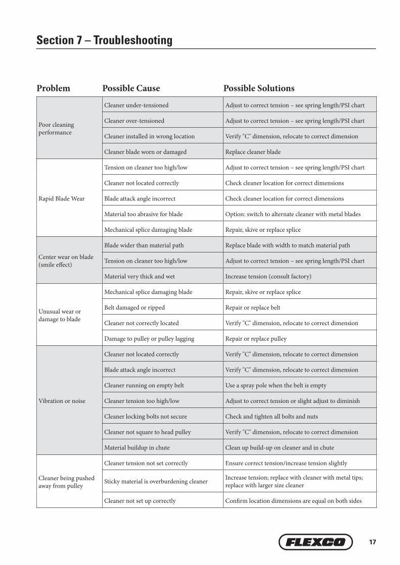
Section 7 – Troubleshooting
Problem Possible Cause Possible Solutions
Poor cleaning performance
Cleaner under-tensioned Adjust to correct tension – see spring length/PSI chart
Cleaner over-tensioned Adjust to correct tension – see spring length/PSI chart
Cleaner installed in wrong location Verify "C" dimension, relocate to correct dimension
Cleaner blade worn or damaged Replace cleaner blade
Rapid Blade Wear
Tension on cleaner too high/low Adjust to correct tension – see spring length/PSI chart
Cleaner not located correctly Check cleaner location for correct dimensions
Blade attack angle incorrect Check cleaner location for correct dimensions
Material too abrasive for blade Option: switch to alternate cleaner with metal blades
Mechanical splice damaging blade Repair, skive or replace splice
Center wear on blade (smile effect)
Blade wider than material path Replace blade with width to match material path
Tension on cleaner too high/low Adjust to correct tension – see spring length/PSI chart
Material very thick and wet Increase tension (consult factory)
Unusual wear or damage to blade
Mechanical splice damaging blade Repair, skive or replace splice
Belt damaged or ripped Repair or replace belt
Cleaner not correctly located Verify "C" dimension, relocate to correct dimension
Damage to pulley or pulley lagging Repair or replace pulley
Vibration or noise
Cleaner not located correctly Verify "C" dimension, relocate to correct dimension
Blade attack angle incorrect Verify "C" dimension, relocate to correct dimension
Cleaner running on empty belt Use a spray pole when the belt is empty
Cleaner tension too high/low Adjust to correct tension or slight adjust to diminish
Cleaner locking bolts not secure Check and tighten all bolts and nuts
Cleaner not square to head pulley Verify "C" dimension, relocate to correct dimension
Material buildup in chute Clean up build-up on cleaner and in chute
Cleaner being pushed away from pulley
Cleaner tension not set correctly Ensure correct tension/increase tension slightly
Sticky material is overburdening cleaner Increase tension; replace with cleaner with metal tips; replace with larger size cleaner
Cleaner not set up correctly Confirm location dimensions are equal on both sides

18 MHP Precleaner
8.1 Specifications & GuidelinesSection 8 – Specs and CAD Drawings
Specifications:• Maximum Belt Speed ...........................................7.5 m/s (1500 FPM)• Temperature Rating .............................................. -35°C to 82°C (-30°F to 180°F)• Minimum Pulley Diameter ...................................500 mm (20")• Blade Height ..........................................................306 mm (12,25")• Usable Blade Wear Length .................................200 mm (8")• Blade Material ....................................................... Polyurethane 90 durometer (proprietary blend for abrasion resistance and
long wear)• Available for Belt Widths .....................................600 to 2400mm (24" to 96"). Other sizes available upon request.• CEMA Cleaner Rating ...........................................Class 5
Top of washer to top of
torque arm
Pole Length
*
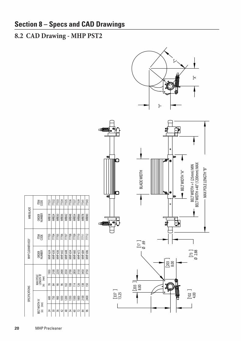
* Each pole size can be used with a blade size either belt width minus 152mm (6"), belt width minus 305mm (12"), or belt width minus 457mm (18").
Max Conveyor Span
Clearance Guidelines for Installation
HORIZONTAL CLEARANCE REQUIRED
VERTICAL CLEARANCE REQUIRED
mm in, mm in,200 8 488 19.5
Pole Length Specifications*
CLEANER SIZEMAX OVERALL POLE LENGTH
CENTER POLE LENGTH
MAXIMUM CONVEYOR SPAN
mm in. mm in. mm in. mm in.600 24 1950 78 600 24 1650 66750 30 2100 84 750 30 1800 72900 36 2250 90 900 36 1950 78
1050 42 2400 96 1050 42 2100 841200 48 2550 102 1200 48 2250 901350 54 2700 108 1350 54 2400 961500 60 2850 114 1500 60 2550 1021800 72 3150 126 1800 72 2850 1142100 84 3450 138 2100 84 3150 1262400 96 3750 150 2400 96 3450 138
* For special extra long pole length requirements a Pole Extender Kit (#76024) is available that provides 750mm (30") of extended pole length. Pole Diameter - 73 mm (2 -7/8")
Spring Length Chart MetricBlade Width
White Springs
Silver Springs
Red Springs
450 146 162 165600 137 159 162750 130 156 162900 121 156 159
1050 114 152 1591200 N/A 149 1561350 N/A 146 1561500 N/A 146 1521650 N/A 143 1521800 N/A 140 1491950 N/A 130 1492100 N/A N/A 1462250 N/A N/A 1432400 N/A N/A 1402550 N/A N/A 140
Shading indicates preferred spring option.
Spring Length Chart ImperialBlade Width
White Springs
Silver Springs
Red Springs
18" 5 3/4" 6 3/8" 6 1/2"24" 5 3/8" 6 1/4" 6 3/8"30" 5 1/8" 6 1/8" 6 3/8"36" 4 3/4" 6 1/8" 6 1/4"42" 4 1/2" 6" 6 1/4"48" N/A 5 7/8" 6 1/8"54" N/A 5 3/4" 6 1/8"60" N/A 5 3/4" 6"66" N/A 5 5/8" 6"72" N/A 5 1/2" 5 7/8"78" N/A 5 1/8" 5 7/8"84" N/A N/A 5 3/4"90" N/A N/A 5 5/8"96" N/A N/A 5 1/2"
102" N/A N/A 5 1/2"Shading indicates preferred spring option.
Vertical
Horizontal
Pressure Chart
Blade WidthPSImm in.
450 18" 8#600 24" 10#800 32" 13#900 36" 15#
1050 42" 18#1200 48" 20#1350 54" 23#1500 60" 25#1650 66" 28#1800 72" 31#1950 78" 33#2100 84" 36#2250 90" 38#2400 96" 41#2550 102" 43#

19
8.1 Specifications & Guidelines (cont.)
Pole Location Specs
A = Pulley Diameter + Lagging and BeltC = Critical Spec to move location if necessary
A X
C Y
Move Dim. Con arc
Section 8 – Specs and CAD Drawings
X & Y Chart for Pole LocationPulley Diameter (including belt and lagging) X Y C
500 250 365 442525 263 365 450550 275 365 457575 288 365 465600 300 365 472625 313 365 480650 325 365 489675 338 365 497700 350 365 506725 363 365 514750 375 365 523775 388 365 532800 400 365 542825 413 365 551850 425 365 560875 438 365 570900 450 365 579925 463 365 589950 475 365 599975 488 365 609
1000 500 365 6191025 513 365 6291050 525 365 6391075 538 365 6501100 550 365 660
X & Y Chart for Pole LocationPulley Diameter (including belt and lagging) X Y C
1125 563 365 6711150 575 365 6811175 588 365 6921200 600 365 7021225 613 365 7141250 628 365 7271275 641 365 7381300 657 365 7521325 672 365 7651350 685 365 7761375 700 365 7901400 713 365 8011425 728 365 8151450 741 365 8261475 757 365 8401500 769 365 8511525 782 365 8631550 797 365 8771575 810 365 8881600 826 365 9031625 838 365 9141650 850 365 9251675 866 365 9401700 879 365 9511725 891 365 963
X & Y Chart for Pole LocationPulley Diameter (including belt and lagging) X Y C
1750 906 365 9771775 919 365 9891800 932 365 10011825 947 365 10151850 960 365 10271875 972 365 10391900 985 365 10501925 1000 365 10641950 1013 365 10771975 1026 365 10892000 1038 365 11002025 1053 365 11142050 1066 365 11272075 1079 365 11392100 1090 365 1150
20 MHP Precleaner
Section 8 – Specs and CAD Drawings
8.2 CAD Drawing - MHP PST2SP
ECIF
ICAT
IONS
MHP
CLE
ANER
ASS
YM
RB B
LADE
BELT
WID
TH 'A
'(in
) (
mm)
MAX
POL
E LE
NGTH
'B'
(in)
(mm
)
ORDE
R NU
MBE
RIT
EM
CODE
ORDE
R NU
MBE
RIT
EM
CODE
2460
078
1950
MHP
-624
7770
3M
RB18
7753
130
750
8421
00M
HP-6
3077
704
MRB
2477
532
3690
090
2250
MHP
-636
7770
5M
RB30
7753
342
1050
9624
00M
HP-6
4277
706
MRB
3677
534
4812
0010
225
50M
HP-6
4877
707
MRB
4277
535
5413
5010
827
00M
HP-6
5477
708
MRB
4877
536
6015
0011
428
50M
HP-6
6077
709
MRB
5477
537
7218
0012
631
50M
HP-6
7277
710
MRB
6677
539
8421
0013
834
50M
HP-6
8477
711
MRB
7877
541
9624
0015
037
50M
HP-6
9677
712
MRB
9077
543
BELT
WID
TH +
40" (
1200
mm
) MAX
BELT
WID
TH +
1 (2
5mm
) MIN
MAX
POL
E LEN
GTH
"B"
BELT
WID
TH "A
"
BLAD
E WID
TH
Ø2.8
873
"X"
"Y"
"C"
8.00
203
8.00
203
13.2533
7
4.00
102
Ø.6917
21
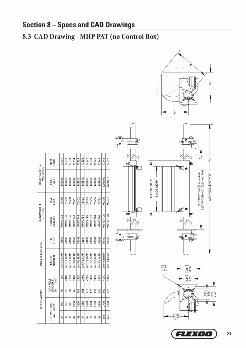
Section 8 – Specs and CAD Drawings
8.3 CAD Drawing - MHP PAT (no Control Box)
MA
X PO
LE L
ENG
TH "B
"
BELT
WID
TH "A
"
BLA
DE
WID
TH
BELT
WID
TH +
40" (
1200
mm
) MA
XBE
LT W
IDTH
+1
(25m
m) M
IN
"X"
"Y"
"C"
13.2
533
7
8.0020
3
5.7514
6
5.7514
6
8.0020
3
.66
17
SPEC
IFIC
ATI
ON
SM
HP
CLEA
NER
ASS
YIT
EM N
UM
BER
1CT
R PO
LEIT
EM N
UM
BER
2M
RB B
LAD
E
BELT
WID
TH 'A
'(in
)
(mm
)M
AX
POLE
LE
NG
TH 'B
'(in
)
(m
m)
ORD
ER
NU
MBE
RIT
EM
COD
EO
RDER
N
UM
BER
ITEM
CO
DE
ORD
ER
NU
MBE
RIT
EM
COD
E
2460
078
1950
MH
P-62
4AP
7859
9M
MPC
P24
7645
8M
RB18
7753
130
750
8421
00M
HP-
630A
P78
600
MM
PCP3
076
459
MRB
2477
532
3690
090
2250
MH
P-63
6AP
7860
1M
MPC
P36
7646
0M
RB30
7753
342
1050
9624
00M
HP-
642A
P78
602
MM
PCP4
276
461
MRB
3677
534
4812
0010
225
50M
HP-
648A
P78
603
MM
PCP4
876
462
MRB
4277
535
5413
5010
827
00M
HP-
654A
P78
604
MM
PCP5
476
463
MRB
4877
536
6015
0011
428
50M
HP-
660A
P78
605
MM
PCP6
076
464
MRB
5477
537
7218
0012
631
50M
HP-
672A
P78
606
MM
PCP7
276
465
MRB
6677
539
8421
0013
834
50M
HP-
684A
P78
607
MM
PCP8
476
466
MRB
7877
541
9624
0015
037
50M
HP-
696A
P78
608
MM
PCP9
677
722
MRB
9077
543
108
2700
162
4050
MH
P-61
08A
P90
160
MM
PCP1
0890
326
MRB
102
7754
512
030
0017
443
50M
HP-
6120
AP
9016
1M
MPC
P120
9032
7M
RB11
477
547

22 MHP Precleaner
9.1 Replacement Parts ListSection 9 – Replacement Parts
PAT Air & Nitrogen Tensioner Replacement Parts
*Hardware IncludedLead time: 1 working day
REF DESCRIPTIONORDERING NUMBER
ITEM CODE
WT. Kg.
9 Air/Water Bag (1 ea.) AWTB 75905 1.710 Mounting Base (1 ea.) AWTMB 75906 1.311 Torque Arm * (1 ea.) AWTA 75907 0.712 Hose Kit (50' of hose and 6 hose clamps) AWTHK 75909 3.013 PAT Control Box PACB 78683 5.0
14 AWT Pole Bearing Assy (for cleaners shipped after 4/2016) AWTPBA 90000 1.0
- PAT Kit- AWT Tensioner w/Control Box (includes 2 ea. items 9, 10, 11 & 1 ea. items 12, 13) PAK 78705 39.1
- AWT Air/Water Tensioner w/o Control Box (includes 2 each items 9, 10, 11 & 1 ea. item 12) AWTNCB 76069 34.1
6
8
2
6a6b
3
41
5
7
Replacement Parts
REF DESCRIPTIONORDERING NUMBER
ITEM CODE
WT. KG.
1
600 mm (24") Center Pole MMPCP24 76458 15.6750 mm (30") Center Pole MMPCP30 76459 19.5900 mm (36") Center Pole MMPCP36 76460 23.41050 mm (42") Center Pole MMPCP42 76461 27.21200 mm (48") Center Pole MMPCP48 76462 31.21350 mm (54") Center Pole MMPCP54 76463 35.11500 mm (60") Center Pole MMPCP60 76464 39.01800 mm (72") Center Pole MMPCP72 76465 46.82100 mm (84") Center Pole MMPCP84 76808 54.62400 mm (96") Center Pole MMPCP96 77722 62.4
2 Extender Pole Kit (2 ea.) MHP-EP 76392 24.53 Mounting Plate Kit* (2 ea.) MHPMPK 77727 20.14 Blade Pin Kit* (1 ea.) MHPBPK 77728 0.45 Torque Pivot Kit* (1 ea.) PTPK 75897 3.2
6 Tension Spring - White (1 ea.) for blades 450 - 1050mm (18" - 42") PSTS-W 75898 0.8
6a Tension Spring - Silver (1 ea.) for blades 120 - 1950mm (48" - 78") PSTS-S 75899 1.4
6b Tension Spring - Red (1 ea.) for blades 2100 - 2250mm (84" - 90") PSTS-R 77726 2.0
7 Torque Arm Kit* (1 ea.) PSTA 75896 5.28 Bushing Kit (2 ea.) QMTBK-W 76098 0.1
-PST Spring Tensioner* - White (incl. 2 ea. Items 3, 5, 6, 7, & 8) for blades 450 - 1050mm (18" - 42")
PST2-W 77723 39.1
-PST Spring Tensioner* - Silver (incl. 2 ea. Items 3, 5, 6a, 7a, & 8) for blades 120 - 1950mm (48" - 78")
PST2-S 77724 39.6
-PST Spring Tensioner* - Red (incl. 2 ea. Items 3, 5, 6b, 7b, & 8) for blades 2100 - 2250mm (84" - 90")
PST2-R 77725 40.3
*Hardware IncludedLead Time: 1 working day
Spring Tensioner Selection Chart
CLEANER BLADE WIDTH77723
PST2-W77724
PST2-S77725
PST2-RMegaShear 450 - 1050mm (18" - 42") XMegaShear 120 - 1950mm (48" - 78") XMegaShear 2100 - 2250mm (84" - 90") X
9
10
12
13 14
14
11


25
Section 10 – Other Flexco Conveyor Products
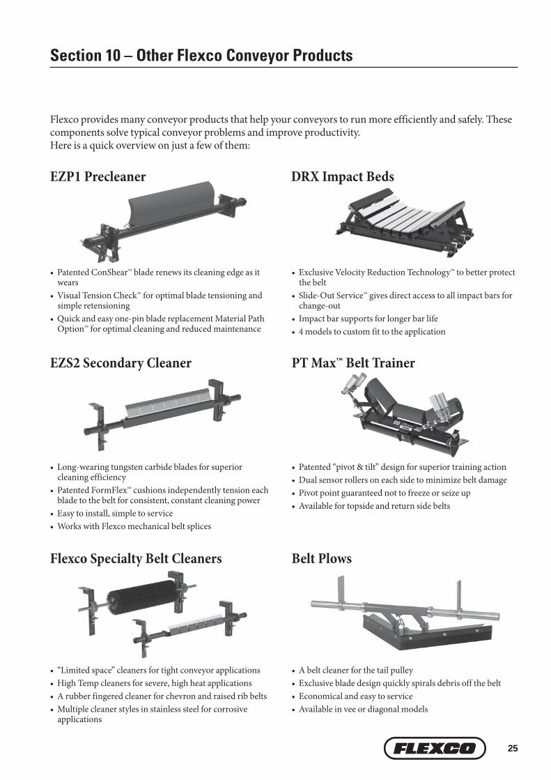
Flexco provides many conveyor products that help your conveyors to run more efficiently and safely. These components solve typical conveyor problems and improve productivity. Here is a quick overview on just a few of them:
• Patented ConShear™ blade renews its cleaning edge as it wears
• Visual Tension Check™ for optimal blade tensioning and simple retensioning
• Quick and easy one-pin blade replacement Material Path Option™ for optimal cleaning and reduced maintenance
EZS2 Secondary Cleaner
• Patented “pivot & tilt” design for superior training action• Dual sensor rollers on each side to minimize belt damage• Pivot point guaranteed not to freeze or seize up• Available for topside and return side belts
• Exclusive Velocity Reduction Technology™ to better protect the belt
• Slide-Out Service™ gives direct access to all impact bars for change-out
• Impact bar supports for longer bar life• 4 models to custom fit to the application
• A belt cleaner for the tail pulley• Exclusive blade design quickly spirals debris off the belt• Economical and easy to service• Available in vee or diagonal models
PT Max™ Belt Trainer
DRX Impact Beds
Belt Plows
• Long-wearing tungsten carbide blades for superior cleaning efficiency
• Patented FormFlex™ cushions independently tension each blade to the belt for consistent, constant cleaning power
• Easy to install, simple to service• Works with Flexco mechanical belt splices
• “Limited space” cleaners for tight conveyor applications• High Temp cleaners for severe, high heat applications• A rubber fingered cleaner for chevron and raised rib belts• Multiple cleaner styles in stainless steel for corrosive
applications
Flexco Specialty Belt Cleaners
EZP1 Precleaner

The Flexco Vision
To become the leader in maximising belt conveyor productivity for our customers worldwide
through superior service and innovation.
240 Macpherson Road • #02-01 • Singapore 348574 Tel: +65-6484-1533 • Fax: +65-6484-1531 • E-mail: [email protected]
Visit www.flexco.com for other Flexco locations and products.
©2019 Flexible Steel Lacing Company. 06/26/19. For reorder: X4238