installation, operation and maintenance instructions · pdf fileinstallation, operation and...
TRANSCRIPT
Installation, Operation and Maintenance Instructions
Model 3500XD
Medium Consistency
Pump System
FOREWORDThis manual provides instructions for the Installation, Operation, and Maintenance of the Goulds Model 3500XD Medium Consistency
Pump. This manual covers the standard product plus common options that are available. For special options, supplemental instructions are
supplied. This manual must be read and understood before installation and start-up.
The design, materials, and workmanship incorporated in the construction of Goulds pumps makes them capable of giving trouble-free
service. The life and satisfactory service of any mechanical unit, however, is enhanced and extended by correct application, proper
installation, periodic inspection, condition monitoring and careful maintenance. This instruction manual was prepared to assist operators in
understanding the construction and the correct methods of installing, operating, and maintaining these mixers.
ITT - Goulds Pumps shall not be liable for physical injury, damage or delays caused by a failure to observe the instructions for
Installation, Operation, and Maintenance contained in this manual.
Warranty is valid only when genuine ITT - Goulds parts are used.
Use of the equipment on a service other than stated in the order will nullify the warranty, unless written approval is obtained in advance
from ITT - Goulds Pumps.
To assure proper installation, supervision from an authorized manufacturer’s representative is recommended.
Additional manuals can be obtained by contacting your local Goulds representative.
THIS MANUAL EXPLAINS
� Proper Installation
� Start-Up Procedures
� Operation Procedures
� Routine Maintenance
� Mixer Overhaul
� Troubleshooting
� Ordering Spare or Repair Parts
2 3500XD IOM 11/10
TABLE OF CONTENTSPAGE
5 PUMP DESCRIPTION
9 INSTALLATION
15 PREPARATION FOR START-UP
17 OPERATION AND CONTROLS
25 MAINTENANCE
3500XD IOM 11/10 3
1
3
2
4
5
SECTION

This page left blank intentionally.
4 3500XD IOM 11/10
S-1
Industrial Process Pump Safety Manual
IMPORTANT SAFETY NOTICE
To: Our Valued Customers
User safety is a major focus in the design of our products. Following the precautions outlined in this manual will minimize your risk of injury.
ITT Goulds pumps will provide safe, trouble-free service when properly installed, maintained, and operated.
Safe installation, operation, and maintenance of ITT Goulds Pumps equipment are an essential end user responsibility. This Pump Safety Manual identifies specific safety risks that must be considered at all times during product life. Understanding and adhering to these safety warnings is mandatory to ensure personnel, property, and/or the environment will not be harmed. Adherence to these warnings alone, however, is not sufficient — it is anticipated that the end user will also comply with industry and corporate safety standards. Identifying and eliminating unsafe installation, operating and maintenance practices is the responsibility of all individuals involved in the installation, operation, and maintenance of industrial equipment.
Please take the time to review and understand the safe installation, operation, and maintenance guidelines outlined in this Pump Safety Manual and the Instruction, Operation, and Maintenance (IOM) manual. Current manuals are available at www.gouldspumps.com/literature_ioms.html or by contacting your nearest Goulds Pumps sales representative.
These manuals must be read and understood before installation and start-up.
For additional information, contact your nearest Goulds Pumps sales representative or visit our Web site at www.gouldspumps.com.

S-2
SAFETY WARNINGS
Specific to pumping equipment, significant risks bear reinforcement above and beyond normal safety precautions.
WARNING
A pump is a pressure vessel with rotating parts that can be hazardous. Any pressure vessel can explode, rupture, or discharge its contents if sufficiently over pressurized causing death, personal injury, property damage, and/or damage to the environment. All necessary measures must be taken to ensure over pressurization does not occur.
WARNING
Operation of any pumping system with a blocked suction and discharge must be avoided in all cases. Operation, even for a brief period under these conditions, can cause superheating of enclosed pumpage and result in a violent explosion. All necessary measures must be taken by the end user to ensure this condition is avoided.
WARNING
The pump may handle hazardous and/or toxic fluids. Care must be taken to identify the contents of the pump and eliminate the possibility of exposure, particularly if hazardous and/or toxic. Potential hazards include, but are not limited to, high temperature, flammable, acidic, caustic, explosive, and other risks.
WARNING
Pumping equipment Instruction, Operation, and Maintenance manuals clearly identify accepted methods for disassembling pumping units. These methods must be adhered to. Specifically, applying heat to impellers and/or impeller retaining devices to aid in their removal is strictly forbidden. Trapped liquid can rapidly expand and result in a violent explosion and injury.
ITT Goulds Pumps will not accept responsibility for physical injury, damage, or delays caused by a failure to observe the instructions for installation, operation, and maintenance contained in this Pump Safety Manual or the current IOM available at www.gouldspumps.com/literature.
S-3
SAFETY DEFINITIONS Throughout this manual the words WARNING, CAUTION, ELECTRICAL, and ATEX are used to indicate where special operator attention is required.
Observe all Cautions and Warnings highlighted in this Pump Safety Manual and the IOM provided with your equipment.
WARNING Indicates a hazardous situation which, if not avoided, could result in death or serious injury.
Example: Pump shall never be operated without coupling guard installed correctly.
CAUTION Indicates a hazardous situation which, if not avoided, could result in minor or moderate injury.
Example: Throttling flow from the suction side may cause cavitation and pump damage.
ELECTRICAL HAZARD Indicates the possibility of electrical risks if directions are not followed.
Example: Lock out driver power to prevent electric shock, accidental start-up, and physical injury.
When installed in potentially explosive atmospheres, the instructions that follow the Ex symbol must be followed. Personal injury and/or equipment damage may occur if these instructions are not followed. If there is any question regarding these requirements or if the equipment is to be modified, please contact an ITT Goulds Pumps representative before proceeding.
Example: Improper impeller adjustment could cause contact between the rotating and stationary parts, resulting in a spark and heat generation.
S-4
GENERAL PRECAUTIONS
WARNING
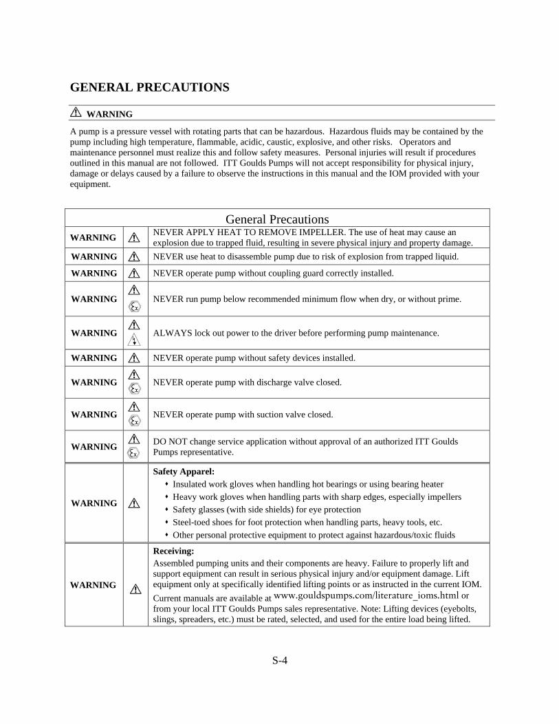
A pump is a pressure vessel with rotating parts that can be hazardous. Hazardous fluids may be contained by the pump including high temperature, flammable, acidic, caustic, explosive, and other risks. Operators and maintenance personnel must realize this and follow safety measures. Personal injuries will result if procedures outlined in this manual are not followed. ITT Goulds Pumps will not accept responsibility for physical injury, damage or delays caused by a failure to observe the instructions in this manual and the IOM provided with your equipment.
General Precautions
WARNING NEVER APPLY HEAT TO REMOVE IMPELLER. The use of heat may cause an explosion due to trapped fluid, resulting in severe physical injury and property damage.
WARNING NEVER use heat to disassemble pump due to risk of explosion from trapped liquid.
WARNING NEVER operate pump without coupling guard correctly installed.
WARNING
NEVER run pump below recommended minimum flow when dry, or without prime.
WARNING
ALWAYS lock out power to the driver before performing pump maintenance.
WARNING NEVER operate pump without safety devices installed.
WARNING
NEVER operate pump with discharge valve closed.
WARNING
NEVER operate pump with suction valve closed.
WARNING
DO NOT change service application without approval of an authorized ITT Goulds Pumps representative.
WARNING
Safety Apparel: Insulated work gloves when handling hot bearings or using bearing heater Heavy work gloves when handling parts with sharp edges, especially impellers Safety glasses (with side shields) for eye protection Steel-toed shoes for foot protection when handling parts, heavy tools, etc. Other personal protective equipment to protect against hazardous/toxic fluids
WARNING
Receiving: Assembled pumping units and their components are heavy. Failure to properly lift and support equipment can result in serious physical injury and/or equipment damage. Lift equipment only at specifically identified lifting points or as instructed in the current IOM. Current manuals are available at www.gouldspumps.com/literature_ioms.html or from your local ITT Goulds Pumps sales representative. Note: Lifting devices (eyebolts, slings, spreaders, etc.) must be rated, selected, and used for the entire load being lifted.
S-5
General Precautions
WARNING
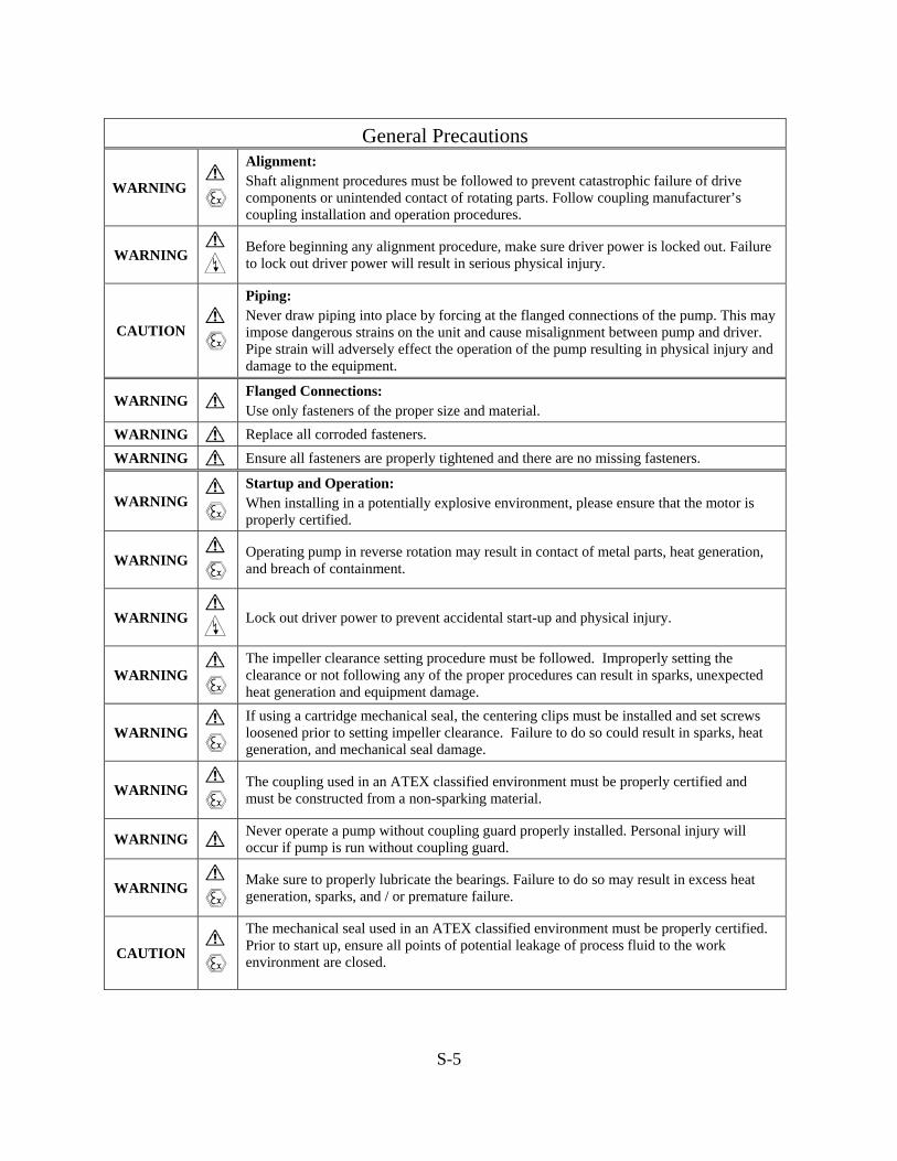
Alignment: Shaft alignment procedures must be followed to prevent catastrophic failure of drive components or unintended contact of rotating parts. Follow coupling manufacturer’s coupling installation and operation procedures.
WARNING
Before beginning any alignment procedure, make sure driver power is locked out. Failure to lock out driver power will result in serious physical injury.
CAUTION
Piping: Never draw piping into place by forcing at the flanged connections of the pump. This may impose dangerous strains on the unit and cause misalignment between pump and driver. Pipe strain will adversely effect the operation of the pump resulting in physical injury and damage to the equipment.
WARNING Flanged Connections: Use only fasteners of the proper size and material.
WARNING Replace all corroded fasteners. WARNING Ensure all fasteners are properly tightened and there are no missing fasteners.
WARNING
Startup and Operation: When installing in a potentially explosive environment, please ensure that the motor is properly certified.
WARNING
Operating pump in reverse rotation may result in contact of metal parts, heat generation, and breach of containment.
WARNING Lock out driver power to prevent accidental start-up and physical injury.
WARNING
The impeller clearance setting procedure must be followed. Improperly setting the clearance or not following any of the proper procedures can result in sparks, unexpected heat generation and equipment damage.
WARNING
If using a cartridge mechanical seal, the centering clips must be installed and set screws loosened prior to setting impeller clearance. Failure to do so could result in sparks, heat generation, and mechanical seal damage.
WARNING
The coupling used in an ATEX classified environment must be properly certified and must be constructed from a non-sparking material.
WARNING Never operate a pump without coupling guard properly installed. Personal injury will occur if pump is run without coupling guard.
WARNING
Make sure to properly lubricate the bearings. Failure to do so may result in excess heat generation, sparks, and / or premature failure.
CAUTION
The mechanical seal used in an ATEX classified environment must be properly certified. Prior to start up, ensure all points of potential leakage of process fluid to the work environment are closed.
S-6
General Precautions
CAUTION
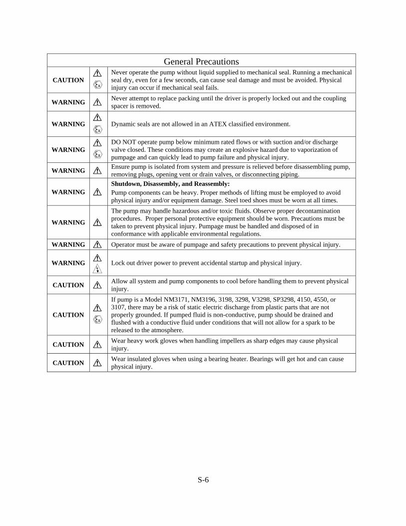
Never operate the pump without liquid supplied to mechanical seal. Running a mechanical seal dry, even for a few seconds, can cause seal damage and must be avoided. Physical injury can occur if mechanical seal fails.
WARNING Never attempt to replace packing until the driver is properly locked out and the coupling spacer is removed.
WARNING
Dynamic seals are not allowed in an ATEX classified environment.
WARNING
DO NOT operate pump below minimum rated flows or with suction and/or discharge valve closed. These conditions may create an explosive hazard due to vaporization of pumpage and can quickly lead to pump failure and physical injury.
WARNING Ensure pump is isolated from system and pressure is relieved before disassembling pump, removing plugs, opening vent or drain valves, or disconnecting piping.
WARNING
Shutdown, Disassembly, and Reassembly: Pump components can be heavy. Proper methods of lifting must be employed to avoid physical injury and/or equipment damage. Steel toed shoes must be worn at all times.
WARNING
The pump may handle hazardous and/or toxic fluids. Observe proper decontamination procedures. Proper personal protective equipment should be worn. Precautions must be taken to prevent physical injury. Pumpage must be handled and disposed of in conformance with applicable environmental regulations.
WARNING Operator must be aware of pumpage and safety precautions to prevent physical injury.
WARNING
Lock out driver power to prevent accidental startup and physical injury.
CAUTION Allow all system and pump components to cool before handling them to prevent physical injury.
CAUTION
If pump is a Model NM3171, NM3196, 3198, 3298, V3298, SP3298, 4150, 4550, or 3107, there may be a risk of static electric discharge from plastic parts that are not properly grounded. If pumped fluid is non-conductive, pump should be drained and flushed with a conductive fluid under conditions that will not allow for a spark to be released to the atmosphere.
CAUTION Wear heavy work gloves when handling impellers as sharp edges may cause physical injury.
CAUTION Wear insulated gloves when using a bearing heater. Bearings will get hot and can cause physical injury.

S-7
ATEX CONSIDERATIONS and INTENDED USE Special care must be taken in potentially explosive environments to ensure that the equipment is properly maintained. This includes but is not limited to:
1. Monitoring the pump frame and liquid end temperature. 2. Maintaining proper bearing lubrication. 3. Ensuring that the pump is operated in the intended hydraulic range.
The ATEX conformance is only applicable when the pump unit is operated within its intended use. Operating, installing or maintaining the pump unit in any way that is not covered in the Instruction, Operation, and Maintenance manual (IOM) can cause serious personal injury or damage to the equipment. This includes any modification to the equipment or use of parts not provided by ITT Goulds Pumps. If there is any question regarding the intended use of the equipment, please contact an ITT Goulds representative before proceeding. Current IOMs are available at www.gouldspumps.com/literature_ioms.html or from your local ITT Goulds Pumps Sales representative.
All pumping unit (pump, seal, coupling, motor and pump accessories) certified for use in an ATEX classified environment, are identified by an ATEX tag secured to the pump or the baseplate on which it is mounted. A typical tag would look like this:
The CE and the Ex designate the ATEX compliance. The code directly below these symbols reads as follows:
II = Group 2 2 = Category 2 G/D = Gas and Dust present T4 = Temperature class, can be T1 to T6 (see Table 1)
Table 1
Code
Max permissible surface temperature
oF (oC)
Max permissible liquid temperature
oF (oC) T1 842 (450) 700 (372)
T2 572 (300) 530 (277)
T3 392 (200) 350 (177)
T4 275 (135) 235 (113)
T5 212 (100) Option not available
T6 185 (85) Option not available
The code classification marked on the equipment must be in accordance with the specified area where the equipment will be installed. If it is not, do not operate the equipment and contact your ITT Goulds Pumps sales representative before proceeding.

S-8
PARTS
The use of genuine Goulds parts will provide the safest and most reliable operation of your pump. ITT Goulds Pumps ISO certification and quality control procedures ensure the parts are manufactured to the highest quality and safety levels. Please contact your local Goulds representative for details on genuine Goulds parts.
PUMP DESCRIPTIONRECEIVING THE PUMP . . . . . . . . . . . . . . . . . . . . . . . . . . . . . . . 5
INTRODUCTION . . . . . . . . . . . . . . . . . . . . . . . . . . . . . . . . . . . 6
DESIGN CONCEPT . . . . . . . . . . . . . . . . . . . . . . . . . . . . . . . . . . 6
CONSTRUCTION DETAILS . . . . . . . . . . . . . . . . . . . . . . . . . . . . . 7
RECEIVING THE PUMP
�! WARNING
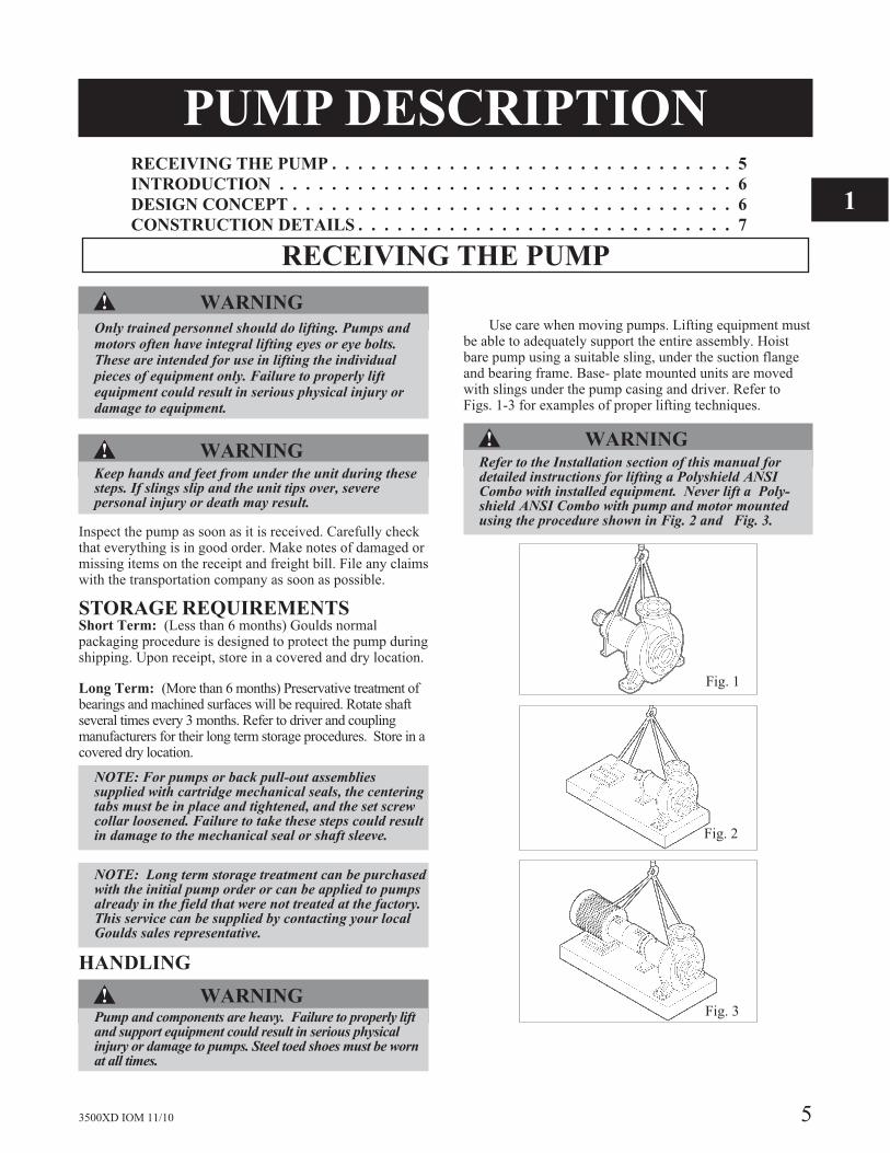
Only trained personnel should do lifting. Pumps andmotors often have integral lifting eyes or eye bolts.These are intended for use in lifting the individualpieces of equipment only. Failure to properly liftequipment could result in serious physical injury ordamage to equipment.
�! WARNINGKeep hands and feet from under the unit during thesesteps. If slings slip and the unit tips over, severepersonal injury or death may result.
Inspect the pump as soon as it is received. Carefully checkthat everything is in good order. Make notes of damaged ormissing items on the receipt and freight bill. File any claimswith the transportation company as soon as possible.
STORAGE REQUIREMENTSShort Term: (Less than 6 months) Goulds normalpackaging procedure is designed to protect the pump duringshipping. Upon receipt, store in a covered and dry location.
Long Term: (More than 6 months) Preservative treatment ofbearings and machined surfaces will be required. Rotate shaftseveral times every 3 months. Refer to driver and couplingmanufacturers for their long term storage procedures. Store in acovered dry location.
NOTE: For pumps or back pull-out assembliessupplied with cartridge mechanical seals, the centeringtabs must be in place and tightened, and the set screwcollar loosened. Failure to take these steps could resultin damage to the mechanical seal or shaft sleeve.
NOTE: Long term storage treatment can be purchasedwith the initial pump order or can be applied to pumpsalready in the field that were not treated at the factory.This service can be supplied by contacting your localGoulds sales representative.
HANDLING
�! WARNINGPump and components are heavy. Failure to properly liftand support equipment could result in serious physicalinjury or damage to pumps. Steel toed shoes must be wornat all times.
Use care when moving pumps. Lifting equipment mustbe able to adequately support the entire assembly. Hoistbare pump using a suitable sling, under the suction flangeand bearing frame. Base- plate mounted units are movedwith slings under the pump casing and driver. Refer toFigs. 1-3 for examples of proper lifting techniques.
�! WARNINGRefer to the Installation section of this manual fordetailed instructions for lifting a Polyshield® ANSICombo with installed equipment. Never lift a Poly-shield® ANSI Combo with pump and motor mountedusing the procedure shown in Fig. 2 and Fig. 3.
3500XD IOM 11/10 5
Fig. 1
Fig. 2
Fig. 3
1
INTRODUCTION
The Goulds Model 3500XD heavy duty stock pump is acentrifugal pump designed to handle paper stock up toapproximately 16% O.D. consistency. The pump design
incorporates special features to induce flow into the pumpsuction and to remove air that is present in stock at higherconsistencies.
DESIGN CONCEPT
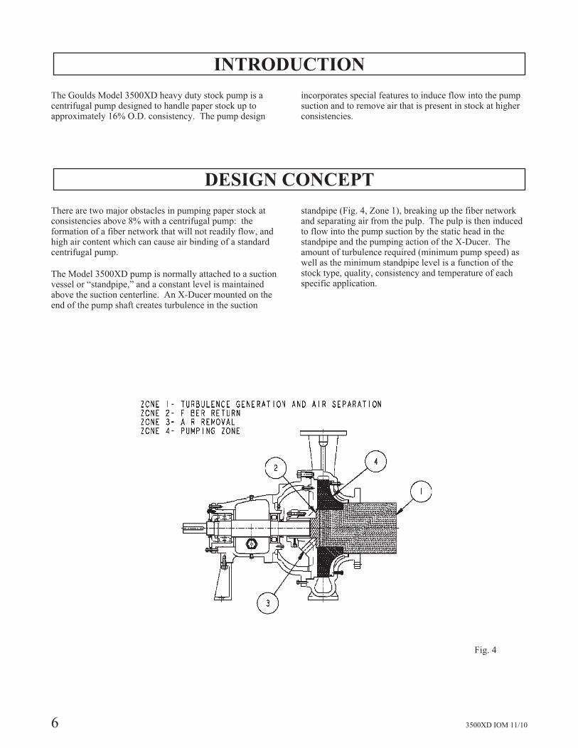
There are two major obstacles in pumping paper stock atconsistencies above 8% with a centrifugal pump: theformation of a fiber network that will not readily flow, andhigh air content which can cause air binding of a standardcentrifugal pump.
The Model 3500XD pump is normally attached to a suctionvessel or “standpipe,” and a constant level is maintainedabove the suction centerline. An X-Ducer mounted on theend of the pump shaft creates turbulence in the suction
standpipe (Fig. 4, Zone 1), breaking up the fiber networkand separating air from the pulp. The pulp is then inducedto flow into the pump suction by the static head in thestandpipe and the pumping action of the X-Ducer. Theamount of turbulence required (minimum pump speed) aswell as the minimum standpipe level is a function of thestock type, quality, consistency and temperature of eachspecific application.
6 3500XD IOM 11/10
Fig. 4
Air separation occurs due to the action of X-Ducer in Zone1. The air collects at the center of the X-Ducer and ispumped through balance holes in the impeller shroud. Anyremaining paper stock is separated from the air behind theimpeller via a patented secondary separation device (U.S.Patent #5,087,171) in Zone 2. The paper
stock is pumped to the casing volute via large backpump-out vanes (Zone 4), and the air flows to atmosphereor to a vacuum source depending on operating conditions(Zone 3).
Pressure generation takes place in the impeller and casingvolute in the normal manner once the air has been removed(Zone 4).
CONSTRUCTION DETAILS
Casing - The casing is vertically split, top centerlinedischarge, providing a back pullout design for ease ofmaintenance. A renewable sideplate is incorporated intothe design to reduce maintenance costs. The sideplate issealed with an O-ring and gasket.
Impeller - The impeller is an open design with a full backshroud. It is designed for a matched close clearance withthe suction sideplate to provide optimum efficiency. Theimpeller has balance holes to allow air to pass through theback shroud. Remaining paper stock is returned to thecasing volute via large pump-out vanes.
The impeller is keyed to the shaft and sealed with Teflon®
O-rings.
X-Ducer - The X-Ducer creates turbulence in the standpipeand feeds the pulp into the pump suction. The designconcentrates the air present in the pulp suspension where itis expelled from the degas holes in the impeller into thedegas system. The X-Ducer is key driven and secured tothe shaft with a rotor nut. Teflon®o-rings protect the shaft.
Repeller - A patented (U.S. Patent # 5,087,171) repellerbehind the impeller provides superior secondary airseparation. The repeller is keyed to the shaft and sealed
with Teflon® O-rings.
Stuffing Box Cover - The stuffing box cover contains adegasification nozzle through which excess air is removed.Shaft sealing is accomplished with a mechanical seal asstandard.
Shaft/Shaft Sleeve - The shaft is designed to minimizedeflection in the seal area and at the impeller. It isprotected from the pumpage by a replaceable sleeve sealedwith a Teflon® O-ring.
Power End - A heavy duty power end is provided formaximum reliability. It includes a duplex angular contactthrust bearing and a cylindrical roller radial bearing formaximum load carrying ability. The bearings are sized fora two year minimum L'
10(14 year average) life under the
worst operating conditions. Oil lubrication is standard andthe frame is sealed at both ends with labyrinth oil seals.External axial adjustment is provided to maintain theproper impeller clearance for optimum efficiency.
3500XD IOM 11/10 7
1

8 3500XD IOM 11/10
This page left blank intentionally.
INSTALLATIONSITE/FOUNDATION . . . . . . . . . . . . . . . . . . . . . . . . . . . . . . . . . 9
LEVEL BASEPLATE . . . . . . . . . . . . . . . . . . . . . . . . . . . . . . . . 10
ALIGNMENT AND ALIGNMENT PROCEDURE . . . . . . . . . . . . . . . . 10
Alignment Checks . . . . . . . . . . . . . . . . . . . . . . . . . . . . . . . . . . . . . . . . . . . . . . . . . . 10
Alignment Criteria . . . . . . . . . . . . . . . . . . . . . . . . . . . . . . . . . . . . . . . . . . . . . . . . . . 11
Set Up. . . . . . . . . . . . . . . . . . . . . . . . . . . . . . . . . . . . . . . . . . . . . . . . . . . . . . . . . . . . 11
Measurement . . . . . . . . . . . . . . . . . . . . . . . . . . . . . . . . . . . . . . . . . . . . . . . . . . . . . . 11
Angular Alignment . . . . . . . . . . . . . . . . . . . . . . . . . . . . . . . . . . . . . . . . . . . . . . . . . 11
Parallel Alignment . . . . . . . . . . . . . . . . . . . . . . . . . . . . . . . . . . . . . . . . . . . . . . . . . . 12
Complete Alignment . . . . . . . . . . . . . . . . . . . . . . . . . . . . . . . . . . . . . . . . . . . . . . . . 13
ALIGNMENT TROUBLESHOOTING . . . . . . . . . . . . . . . . . . . . . . . 13
GROUT BASEPLATE . . . . . . . . . . . . . . . . . . . . . . . . . . . . . . . . 14
Alignment Check . . . . . . . . . . . . . . . . . . . . . . . . . . . . . . . . . . . . . . . . . . . . . . . . . . . 14
PIPING. . . . . . . . . . . . . . . . . . . . . . . . . . . . . . . . . . . . . . . . . 14
General. . . . . . . . . . . . . . . . . . . . . . . . . . . . . . . . . . . . . . . . . . . . . . . . . . . . . . . . . . . 14
SITE / FOUNDATION
A pump should be located near the supply of liquid andhave adequate space for operation, maintenance, andinspection.
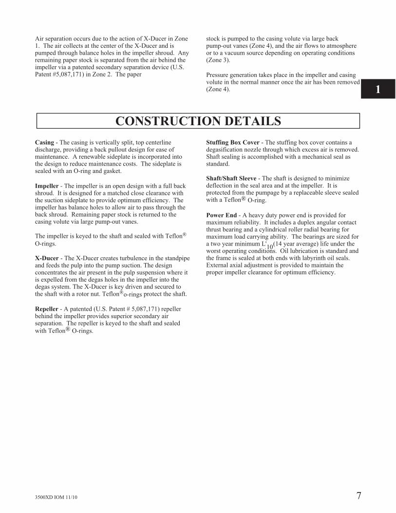
Baseplate mounted pumps are normally grouted on aconcrete foundation, which has been poured on a solidfooting. The foundation must be able to absorb anyvibration and to form a permanent, rigid support for thepumping unit.
The location and size of the foundation bolts are shown onthe outline assembly drawing, provided with the pump datapackage.
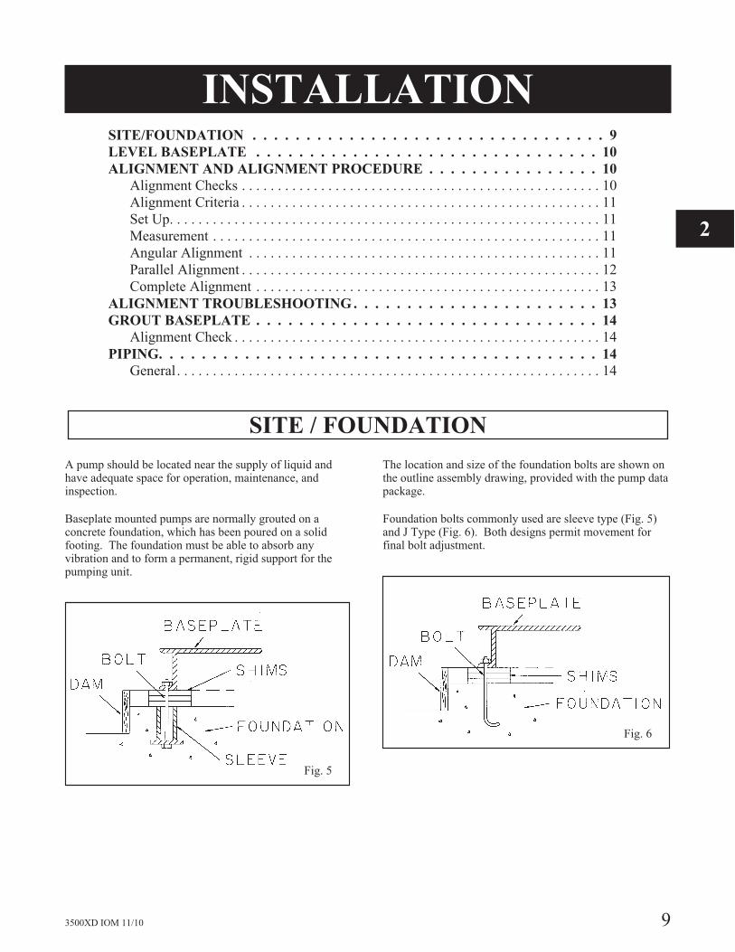
Foundation bolts commonly used are sleeve type (Fig. 5)and J Type (Fig. 6). Both designs permit movement forfinal bolt adjustment.
3500XD IOM 11/10 9
Fig. 5
Fig. 6
2
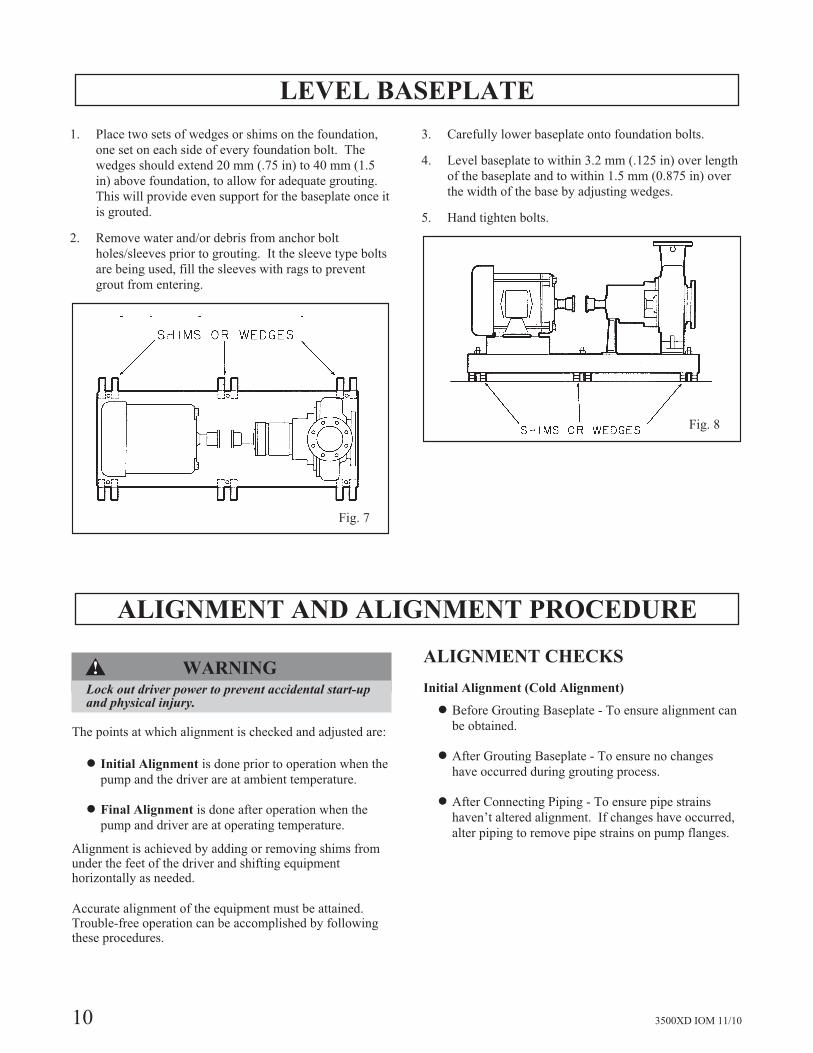
LEVEL BASEPLATE
1. Place two sets of wedges or shims on the foundation,
one set on each side of every foundation bolt. The
wedges should extend 20 mm (.75 in) to 40 mm (1.5
in) above foundation, to allow for adequate grouting.
This will provide even support for the baseplate once it
is grouted.
2. Remove water and/or debris from anchor bolt
holes/sleeves prior to grouting. It the sleeve type bolts
are being used, fill the sleeves with rags to prevent
grout from entering.
3. Carefully lower baseplate onto foundation bolts.
4. Level baseplate to within 3.2 mm (.125 in) over length
of the baseplate and to within 1.5 mm (0.875 in) over
the width of the base by adjusting wedges.
5. Hand tighten bolts.
ALIGNMENT AND ALIGNMENT PROCEDURE
�! WARNINGLock out driver power to prevent accidental start-upand physical injury.
The points at which alignment is checked and adjusted are:
� Initial Alignment is done prior to operation when the
pump and the driver are at ambient temperature.
� Final Alignment is done after operation when the
pump and driver are at operating temperature.
Alignment is achieved by adding or removing shims fromunder the feet of the driver and shifting equipmenthorizontally as needed.
Accurate alignment of the equipment must be attained.Trouble-free operation can be accomplished by followingthese procedures.
ALIGNMENT CHECKS
Initial Alignment (Cold Alignment)
� Before Grouting Baseplate - To ensure alignment can
be obtained.
� After Grouting Baseplate - To ensure no changes
have occurred during grouting process.
� After Connecting Piping - To ensure pipe strains
haven’t altered alignment. If changes have occurred,
alter piping to remove pipe strains on pump flanges.
10 3500XD IOM 11/10
Fig. 7
Fig. 8
Final Alignment (Hot Alignment)
� After First Run - To obtain correct alignment when
both pump and driver are at operating temperature.
Thereafter, alignment should be checked periodically
in accordance with plant operating procedures.
ALIGNMENT CRITERIA
Good alignment is achieved when the dial indicatorreadings as specified in the alignment procedure are .05mm (.002 in.) Total Indicated Reading (T.I.R.) or lesswhen the pump and driver are at operating temperature(Final Alignment).
During the installation phase, however, it is necessary to setthe parallel alignment in the vertical direction to a differentcriteria due to the differences in expansion rates of thepump and driver. Table 1 shows recommended preliminary(cold) settings for electrical motor driven pumps based ondifferent pumpage temperatures. Driver manufacturersshould be consulted for recommended cold settings forother types of drivers (steam turbines, engines, etc.)
Table 1Cold Setting of Parallel
Vertical Alignment
PumpageTemperature
Set Driver Shaft
10° C (50° F) .05 mm (.002 in.) LOW
65° C (150° F) .03 mm (.001 in.) High
120° C (250° F) .12 mm (.005 in.) High
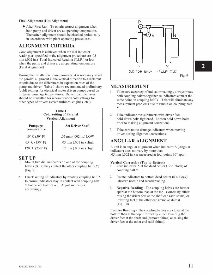
SET UP1. Mount two dial indicators on one of the coupling
halves (X) so they contact the other coupling half (Y)
(Fig. 9).
2. Check setting of indicators by rotating coupling half X
to ensure indicators stay in contact with coupling half
Y but do not bottom out. Adjust indicators
accordingly.
MEASUREMENT1. To ensure accuracy of indicator readings, always rotate
both coupling halves together so indicators contact the
same point on coupling half Y. This will eliminate any
measurement problems due to runout on coupling half
Y.
2. Take indicator measurements with driver feet
hold-down bolts tightened. Loosen hold down bolts
prior to making alignment corrections.
3. Take care not to damage indicators when moving
driver during alignment corrections.
ANGULAR ALIGNMENT
A unit is in angular alignment when indicator A (Angularindicator) does not vary by more than.05 mm (.002 in.) as measured at four points 90° apart.
Vertical Correction (Top-to-Bottom)1. Zero indicator A at top dead center (12 o’clock) of
coupling half Y.
2. Rotate indicators to bottom dead center (6 o’clock).
Observe needle and record reading.
3. Negative Reading - The coupling halves are further
apart at the bottom than at the top. Correct by either
raising the driver feet at the shaft end (add shims) or
lowering feet at the other end (remove shims)
(Fig. 10).
Positive Reading - The coupling halves are closer at thebottom than at the top. Correct by either lowering thedriver feet at the shaft end (remove shims) or raising thedriver feet at the other end (add shims).
3500XD IOM 11/10 11
Fig. 9
2

4. Repeat steps 1-3 until indicator A reads .05 mm (.002
in) or less.
Horizontal Correction (Side-to-Side)1. Zero indicator A on left side of coupling half Y, 90°
from top dead center (9 o’clock).
2. Rotate indicators through top dead center to the right
side, 180° from the start (3 o’clock). Observe needle
and record reading.
3. Negative Reading - The coupling halves are further
apart on the right side than the left. Correct by either
sliding the shaft end of the driver to the left or the
other end to the right.
Positive Reading - The coupling halves are closer
together on the right side than the left. Correct by
either sliding the shaft end of the driver to the right or
the other end to the left (Fig. 11).
4. Repeat steps 1 through 3 until indicator A reads .005
mm (.002 in.) or less.
5. Re-check both horizontal and vertical readings to
ensure adjustment of one did not disturb the other.
Correct as necessary.
PARALLEL ALIGNMENTA unit is in parallel alignment when indicator P (parallelindicator) does not vary by more than .005 mm (.002 in.) asmeasured at four points 90° apart at operating temperature.Note the preliminary vertical cold setting criteria, Table 1.
Vertical Correction (Top-to-Bottom)1. Zero indicator P at top dead center of coupling (12
o’clock) half Y (Fig. 9).
2. Rotate indicator to bottom dead center (6 o’clock).
Observe needle and record reading.
3. Negative Reading - Coupling half X is lower than
coupling half Y. Correct by removing shims of
thickness equal to half of the indicator reading under
each driver foot.
Positive Reading - Coupling half X is higher than
coupling half Y. Correct by adding shims of thickness
equal to half of the indicator reading from each driver
foot (Fig. 12).
NOTE: Equal amounts of shims must be added to orremoved from each driver foot. Otherwise the verticalangular alignment will be affected.
4. Repeat steps 1 through 3 until indicator reads within
.05 mm (.002 in.) or less when hot, or per Table 1
when cold.
Horizontal Correction (Side-to-Side)1. Zero indicator P on the left side of coupling half Y,
90° from top dead center (9 o’clock).
2. Rotate indicators through top dead center to the right
side, 180° from the start (3 o’clock). Observe needle
and record reading.
12 3500XD IOM 11/10
Fig. 11
Fig. 12
Fig. 10
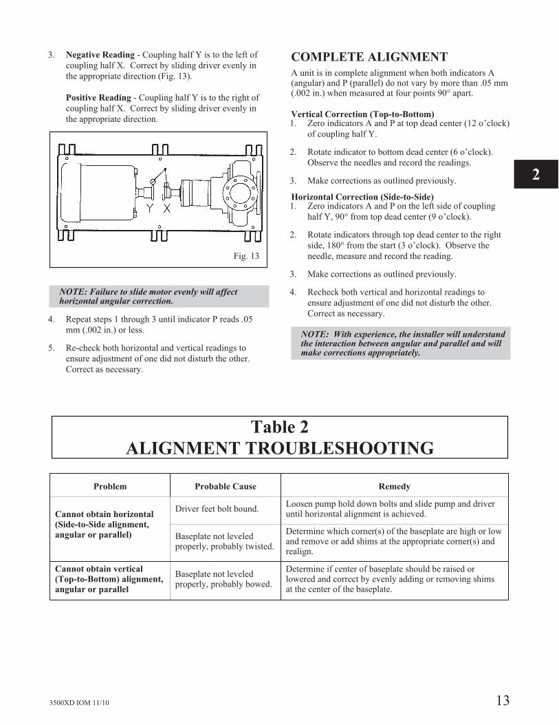
3. Negative Reading - Coupling half Y is to the left of
coupling half X. Correct by sliding driver evenly in
the appropriate direction (Fig. 13).
Positive Reading - Coupling half Y is to the right of
coupling half X. Correct by sliding driver evenly in
the appropriate direction.
NOTE: Failure to slide motor evenly will affecthorizontal angular correction.
4. Repeat steps 1 through 3 until indicator P reads .05
mm (.002 in.) or less.
5. Re-check both horizontal and vertical readings to
ensure adjustment of one did not disturb the other.
Correct as necessary.
COMPLETE ALIGNMENT
A unit is in complete alignment when both indicators A(angular) and P (parallel) do not vary by more than .05 mm(.002 in.) when measured at four points 90° apart.
Vertical Correction (Top-to-Bottom)1. Zero indicators A and P at top dead center (12 o’clock)
of coupling half Y.
2. Rotate indicator to bottom dead center (6 o’clock).
Observe the needles and record the readings.
3. Make corrections as outlined previously.
Horizontal Correction (Side-to-Side)1. Zero indicators A and P on the left side of coupling
half Y, 90° from top dead center (9 o’clock).
2. Rotate indicators through top dead center to the right
side, 180° from the start (3 o’clock). Observe the
needle, measure and record the reading.
3. Make corrections as outlined previously.
4. Recheck both vertical and horizontal readings to
ensure adjustment of one did not disturb the other.
Correct as necessary.
NOTE: With experience, the installer will understandthe interaction between angular and parallel and willmake corrections appropriately.
Table 2
ALIGNMENT TROUBLESHOOTING
Problem Probable Cause Remedy
Cannot obtain horizontal
(Side-to-Side alignment,
angular or parallel)
Driver feet bolt bound.Loosen pump hold down bolts and slide pump and driveruntil horizontal alignment is achieved.
Baseplate not leveledproperly, probably twisted.
Determine which corner(s) of the baseplate are high or lowand remove or add shims at the appropriate corner(s) andrealign.
Cannot obtain vertical
(Top-to-Bottom) alignment,
angular or parallel
Baseplate not leveledproperly, probably bowed.
Determine if center of baseplate should be raised orlowered and correct by evenly adding or removing shimsat the center of the baseplate.
3500XD IOM 11/10 13
2
Fig. 13
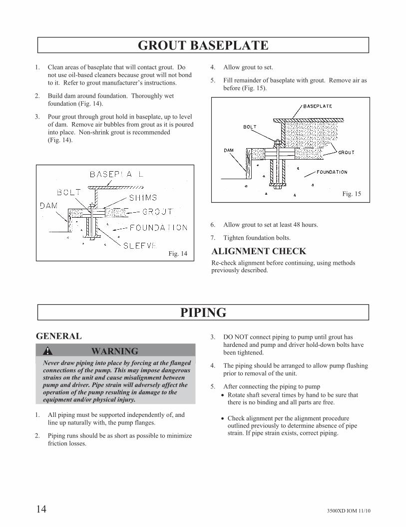
GROUT BASEPLATE
1. Clean areas of baseplate that will contact grout. Do
not use oil-based cleaners because grout will not bond
to it. Refer to grout manufacturer’s instructions.
2. Build dam around foundation. Thoroughly wet
foundation (Fig. 14).
3. Pour grout through grout hold in baseplate, up to level
of dam. Remove air bubbles from grout as it is poured
into place. Non-shrink grout is recommended
(Fig. 14).
4. Allow grout to set.
5. Fill remainder of baseplate with grout. Remove air as
before (Fig. 15).
6. Allow grout to set at least 48 hours.
7. Tighten foundation bolts.
ALIGNMENT CHECK
Re-check alignment before continuing, using methodspreviously described.
PIPING
GENERAL
�! WARNING
Never draw piping into place by forcing at the flangedconnections of the pump. This may impose dangerousstrains on the unit and cause misalignment betweenpump and driver. Pipe strain will adversely affect theoperation of the pump resulting in damage to theequipment and/or physical injury.
1. All piping must be supported independently of, and
line up naturally with, the pump flanges.
2. Piping runs should be as short as possible to minimize
friction losses.
3. DO NOT connect piping to pump until grout has
hardened and pump and driver hold-down bolts have
been tightened.
4. The piping should be arranged to allow pump flushing
prior to removal of the unit.
5. After connecting the piping to pump
� Rotate shaft several times by hand to be sure thatthere is no binding and all parts are free.
� Check alignment per the alignment procedureoutlined previously to determine absence of pipestrain. If pipe strain exists, correct piping.
14 3500XD IOM 11/10
Fig. 14
Fig. 15
PREPARATION FOR START-UPCheck Rotation . . . . . . . . . . . . . . . . . . . . . . . . . . . . . . . . . . . . 15
Check Impeller Axial Clearance . . . . . . . . . . . . . . . . . . . . . . . . . . . 15
Couple Pump And Driver . . . . . . . . . . . . . . . . . . . . . . . . . . . . . . 15
Lubricating Bearings . . . . . . . . . . . . . . . . . . . . . . . . . . . . . . . . . 16
Shaft Sealing . . . . . . . . . . . . . . . . . . . . . . . . . . . . . . . . . . . . . . 16
CHECK ROTATION
NOTE: Serious damage may result if pump is run inthe wrong rotation.
1. Lock out power to driver.
�! WARNINGBefore installation or disassembly of the couplingguard is performed, the driver must be de-energized,the driver controller/starter put in a locked out positionand a caution tag placed at the controller/starterindicating the disconnect. Replace coupling guardbefore resuming normal operation of the pump orserious physical injury may occur. Goulds Pumps, Inc.assumes no liability for avoiding the practice.
2. Make sure coupling hubs are securely fastened to
shafts.
NOTE: Pump is shipped with coupling spacer removed.
3. Unlock driver power.
4. Make sure everyone is clear. Jog driver just long
enough to determine direction of rotation. Rotation
must correspond to arrow on bearing housing.
5. Lock out power to driver.
CHECK IMPELLER AXIALCLEARANCE
�! CAUTION
The impeller clearance setting procedure must befollowed. Improperly setting the clearance can result inequipment damage and heat generation casing failure.
The proper impeller axial clearance is required for properair removal and efficient pump operation. See themaintenance section of this manual for the correct clearanceand method of setting.
COUPLE PUMP AND DRIVER
�! WARNINGBefore installation or disassembly of the couplingguard is performed, the driver must be de-energized,the driver controller/starter put in a locked out positionand a caution tag placed at the controller/starterindicating the disconnect. Replace coupling guardbefore resuming normal operation of the pump orserious physical injury may occur. Goulds Pumps, Inc.assumes no liability for avoiding the practice.
�! CAUTION
Use of couplings which have excessive weight cancause shaft failure and lead to physical injury. Consultpump manufacturer for recommended weight limits forcouplings should the originally supplied coupling bechanged.
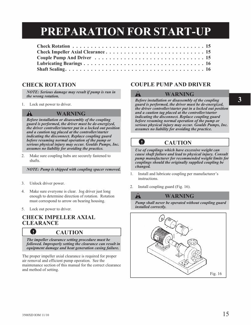
1. Install and lubricate coupling per manufacturer’s
instructions.
2. Install coupling guard (Fig. 16).
�! WARNINGPump shall never be operated without coupling guardinstalled correctly.
3500XD IOM 11/10 15
Fig. 16
3
LUBRICATING BEARINGS
NOTE: Operation of the unit without properlubrication will cause bearing failure, and pumpseizure.
NOTE: Pumps are shipped without oil. Oil lubricatedbearings must be lubricated at the job site.
Oil Lubrication: Pumps are shipped without oil. Fill thebearing frame with oil, through the filler connection(located on top of bearing frame), until the level reaches themark in the middle of the oil level sight-glass. A highquality turbine type oil, with rust and oxidation inhibitorsshould be used.
Refer to the Maintenance Section of this manual for
further details on lubrication.
SHAFT SEALING
�! CAUTION
Never operate the pump without liquid supplied tomechanical seal. Running a mechanical seal dry, evenfor a few seconds, can cause seal damage and must beavoided. Physical injury can occur if mechanical sealfails.
The Model 3500XD pump is supplied with a cartridgemechanical seal as standard. Cartridge seals are preset atthe factory and require no field settings. Remove theholding clips prior to operation to correctly set the seal.Refer to the manufacturer’s outline drawing and instructionmanual for further information.
A fresh water flush is required to lubricate and cool the sealfaces. Refer to the Operation section of this manual fordetails on the seal flush system supplied with the pump.
16 3500XD IOM 11/10
OPERATION AND CONTROLSAIR REMOVAL SYSTEM. . . . . . . . . . . . . . . . . . . . . . . . . . . . . . 17
LEVEL CONTROL - TYPICAL . . . . . . . . . . . . . . . . . . . . . . . . . . 18
DILUTION SYSTEM - TYPICAL. . . . . . . . . . . . . . . . . . . . . . . . . . 20
SEAL / VACUUM FLUSH . . . . . . . . . . . . . . . . . . . . . . . . . . . . . . 21
PUMPING WATER OR LOW CONSISTENCY STOCK. . . . . . . . . . . . . 22
START-UP PROCEDURE . . . . . . . . . . . . . . . . . . . . . . . . . . . . . . 22
SHUTDOWN PROCEDURE . . . . . . . . . . . . . . . . . . . . . . . . . . . . 22
OPERATION WITHOUT VACUUM PUMP. . . . . . . . . . . . . . . . . . . . 23
MONITORING DURING OPERATION . . . . . . . . . . . . . . . . . . . . . . 23
TROUBLESHOOTING . . . . . . . . . . . . . . . . . . . . . . . . . . . . . . . 24
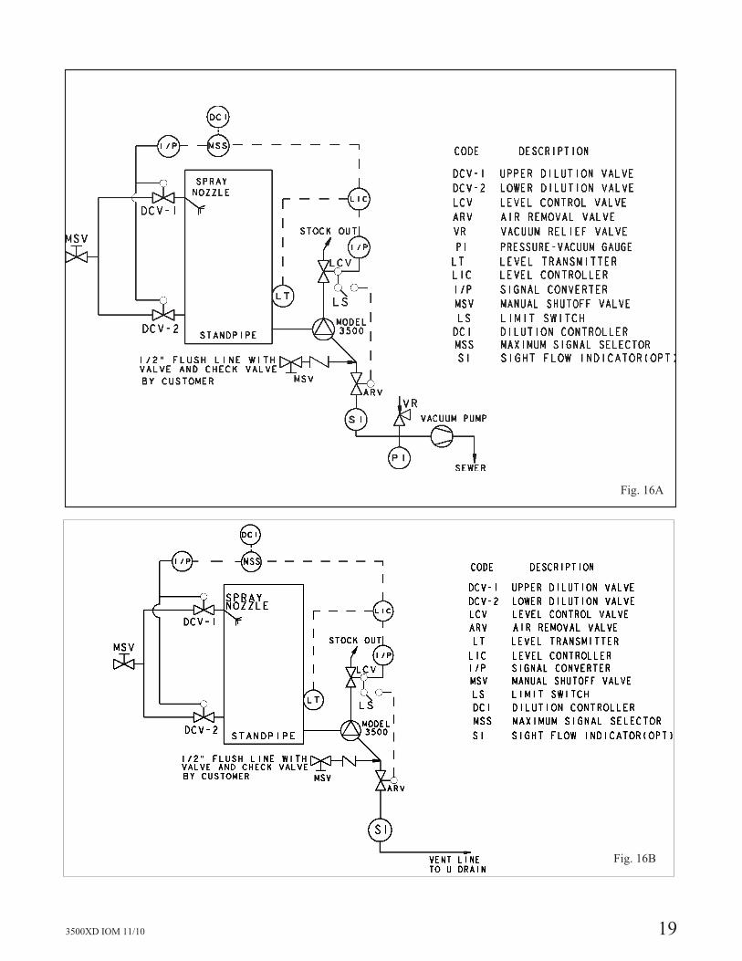
AIR REMOVAL SYSTEM
(General Description - Refer to Figure 16A and 16B)
For Order Specific Description - Refer to the IOM Appendix
For most Model 3500XD installations, the air removalsystem consists of an on/off control valve (ARV), avacuum relief valve (VR), a compound pressure gauge (PI),a vacuum pump and piping from the Model 3500XD to thevacuum pump. (Fig. 16A)
The vacuum pump pumps the air from the Model 3500XD,via the degas piping. The vacuum pump is a Nash ModelAHF75 liquid ring pump operating at 1750, 1450, or 1150RPM. The vacuum pump requires about 2-3 GPM serviceliquid flow (operating and maintenance instructions for theNash vacuum pump are included in the Appendix).
Vacuum pump control is on/auto/off through a switch inthe control room.
In the on mode, the vacuum pump is running. In the automode, the vacuum pump starts when the model 3500XD isstarted, and stops when the Model 3500XD is shutdown.
If the vacuum pump stops during operation, an alarm mustwarn the operator.
The air removal valve (ARV) prevents stock from enteringthe air removal piping when the Model 3500XD is notrunning, or the stock consistency is low.
The air removal valve is equipped with a pneumaticactuator and solenoid valve, with the choice of operationauto/on/off through a switch in the control room. In the onmode, the ARV is 100% open, in the off mode, the ARV isclosed. In the auto mode, the ARV will be open when thelevel control valve (LCV) is open and closed when theLCV is closed.
The vacuum relief valve (VR) is used to control thepressure in the air removal system at a constant setting.The pressure in the air removal piping is indicated on thecompound gauge (PI).
Before start up, the pressure in the degas system should beset at -5 inches Hg (mercury) vacuum gauge. Thisoperation is carried out by starting the vacuum pump withthe ARV closed, and adjusting the VR until a reading of 5in Hg vacuum shows on the compound gauge (PI).
During operation, if fiber is being drawn into the airremoval system, the vacuum level should be reduced byopening the VR valve. If discharge pressure or pumpoperation is erratic, the vacuum level should be increasedby closing the VR valve.
For design pulp consistencies of 10% or less, it is possibleto operate without a vacuum pump with the Model3500XD design. In this case a degas valve would bepresent to allow isolation of the system and the degasnozzle would be piped to drain or an air separator. Refer toFigure 16B for the typical control schematic without avacuum pump.
3500XD IOM 11/10 17
4
LEVEL CONTROL
(Refer to Figure 16A and 16B)
For Order Specific Description - Refer to the IOM Appendix
A level must be maintained in the suction standpipe forproper pump operation and air removal. A level transmitter(LT) must be installed to measure standpipe level andprovide a signal to a level controller in the control room.
The level measurement range is 0 - 100%. This span mustbe oriented properly on the standpipe and the length of thespan will be dependent on the application and the type oflevel transmitter used. Refer to the IOM Appendix for theorder specific information on the level span.
Standpipe level is set on the level controller in the controlroom. Output from the controller is the input to the levelcontrol valve (LCV) on the discharge of the Model3500XD pump.
High and low alarms in the control room should be set at85% and 10% respectively. Neither alarm should beinterlocked to shut down the Model 3500XD. The Model3500XD will not start if the standpipe level is less than10%.
Additional recommendations for level control valveoperations are:
� Low limit stop of 10% open
� In the event of the valve failing closed, a time delayof one minute in the fully closed position shallrequire the 3500XD motor to stop.
The exact operating level for the standpipe must be set foreach specific application to obtain optimum air removaland pump performance. With stock temperatures up to170° F, a level of 3’ to 5’ above the pump centerline istypical. Above 170° F, the level must be increased toaccount for the increased vapor pressure of the stock. Referto the IOM Appendix for the order specific information onthe standpipe operating level, high and low level alarms.
If the unit is equipped with a variable speed drive, outputfrom the level controller would control the pump speedrather than the LCV position. Refer to the IOM Appendixfor the order specific information on the control scheme forvariable speed drive systems.
For Model 3500XD units operating at 10% consistency orless, the level control system is the same as the above.
18 3500XD IOM 11/10
3500XD IOM 11/10 19
Fig. 16B
Fig. 16A

DILUTION SYSTEM – TYPICAL
(Refer to Figure 16A and 16B)
For Order Specific Description - Refer to the IOM Appendix
An automatic standpipe dilution system is recommended sothe highest possible average consistency for which thedischarge piping is designed can be continuously deliveredby the pump. The consistency of the stock being pumped isthe major contributor to friction head loss in the dischargepiping, followed by temperature and pH (this is true only ifthe same fiber type is being pumped). The higher theconsistency, the greater the friction head loss will be.Usually the only parameter or variable that can be adjustedin the standpipe is stock consistency, which can becontrolled by the dilution system.
The dilution system normally consists of an upper spraynozzle with a control valve (DCV-1) and a lower dilutionheader with a control valve (DCV-2)
In the auto mode, the upper dilution valve (DCV-1) willopen to assist pumping when the standpipe level exceeds itsset point by 10%. A maximum signal selector is also usedto allow DCV-1 and DCV-2 to be open a preset amount,while still maintaining the automatic function on anincrease in level.
The normal set point of the standpipe level controller (LCI)is approximately 25%. When the level exceeds 25%, thelevel control valve opens to bring the level back to itsset-point. When the level exceeds 35%, the dilutioncontroller (DCI) will signal the dilution valve (DCV-1) tostart to open. It will open gradually with level and be100% open at 85% level. DCV-1 will gradually close asthe level decreases back to its set-point.
The lower dilution valve (DCV-2) should be programmedto begin opening when DCV-1 is greater than 50% open,and should be 100% open, when DCV-1 is 100% open.Refer to the IOM Appendix for the order specificinformation on the dilution scheme.
If the Model 3500XD is running and the standpipe level isless than 10%, the upper and lower dilution valves willopen 100%. The valves will close when one of the aboveconditions change.
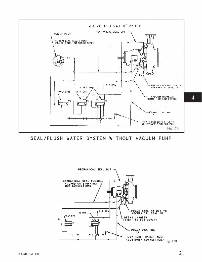
SEAL/VACUUM FLUSH
(Refer to Figure 17A and 17B)
Seal and flush water is manually controlled with aSafematic seal water monitoring unit. The seal water flowto the bearing frame cooling coil and then to themechanical seal is monitored with a 0-2 GPM flow meterand alarm. The seal water from the mechanical seal outletis directed to the gland flush connection or stuffing boxflush connection. Seal water required is 1-1½ GPM. Asecond 0-2 GPM flow meter is supplied to provide 1-2GPM directly to the Model 3500XD vacuum chamber. Athird flow meter (0-4 GPM) with alarm providesapproximately 2 GPM of make-up water directly to thevacuum pump (Fig. 17A).
Check valves are provided to prevent stock from flowingback into the seal and flush water control unit.
The water supply to the seal and flush water monitoringequipment should be clean filtered water with a maximumparticle size of 50 microns, a maximum temperature of100° F (40° C) and supplied at minimum pressure of 50PSIG (3.5 bar). The seal water flow indicators for themechanical seal and the vacuum pump are equipped with
flow switches, which are set to give an alarm if the flowfalls below 50% of the set point. The Model 3500XDpump will not start unless the seal water flow is above theminimum.
For design pulp consistencies at 10% and lower it is notneccessary to utilize a vacuum pump with the Model3500XD. In this situation only two seal flush water flowmeters are required. The flow meter servicing the vacuumpump is not required (Fig. 17B).
�! CAUTION
Never operate the pump without liquid supplied tomechanical seal. Running a mechanical seal dry, evenfor a few seconds, can cause seal damage and must beavoided. Physical injury can occur if mechanical sealfails.
20 3500XD IOM 11/10
3500XD IOM 11/10 21
4
Fig. 17B
Fig. 17A
PUMPING WATER OR LOW CONSISTENCY STOCK
The Model 3500XD pump system should be checked outwith water to make sure everything is operating inaccordance with all alarms and interlocks.
When running with water the air removal valve is closed,otherwise the system will operate the same as if pumpingstock.
PUMPING WITH STOCK - START UP PROCEDURE
Turn the seal water on to the mechanical seal (1 - 1½GPM), the vacuum pump (2 GPM), and to the vacuumchamber (1-2 GPM).
The control switches for the vacuum pump and the airremoval valve are in the automatic mode.
Fill the standpipe with water to a minimum level of 35%with DCV-1 and DCV-2.
With the level control in the auto mode, set the level at35%, start the Model 3500, and open the dilution valvesDCV-1 and DCV-2 to 100%.
The vacuum pump starts.
Begin adding stock to the standpipe. When the stock flowto the standpipe is at normal production, slowly close thedilution valves and switch the dilution controller to auto.
Gradually adjust the set point to the designated level for thespecific service leaving the level controller on automatic.If the pump discharge pressure drops or pumping becomeserratic, slowly increase the level until pumping is normal.
Follow the same sequence for the Model 3500XD for unitswithout a vacuum pump when the consistency is 10% andlower.
�! WARNING
Do not operate pump below minimum rated flows orwith suction and/or discharge valve closed or withsuction and/or discharge line blocked. Theseconditions may create an explosive hazard due tovaporization of pumpage and can quickly lead to pumpfailure and physical injury.
�! WARNINGAssure that the system operating conditions are withinthe capabilities (e.g. – pressure, temperature, power,etc.) of the pump. Exceeding any of the limits couldresult in failure of components resulting in seriousphysical injury and damage to equipment.
SHUTDOWN PROCEDURE
�! WARNING
Do not operate pump below minimum rated flows orwith suction and/or discharge valve closed or withsuction and/or discharge line blocked. These conditionsmay create an explosive hazard due to vaporization ofpumpage and can quickly lead to pump failure andphysical injury.
During brief shutdowns (approximately four hours or less),it is usually sufficient to flush and drain the standpipe,pump and control valve without displacing the stock in theentire discharge line. During extended shutdowns (overfour hours), it is recommended to also flush and drain thedischarge line.
Stop the pulp flow to the standpipe. After the pulp ispumped from the standpipe and the discharge piping hasbeen cleared of stock, the Model 3500XD can be shutdown.
During the shutdown sequence, the dilution system, airremoval valve and vacuum pump should be in the automode. After the Model 3500XD is shut down, the airremoval valve and the vacuum pump switch should bechanged to the off mode.
The seal water to the mechanical seal and the vacuumpump can be shut off. If the seal water to this mechanicalseal is left on, the standpipe can gradually fill up withwater.
22 3500XD IOM 11/10
3500XD IOM 11/10 23
OPERATION WITHOUT A VACUUM PUMP
The Model 3500XD can be supplied both with and without avacuum pump. Services with design pulp consistency of 10%or less can be supplied without a vacuum pump. When avacuum pump is supplied the flowing operating instructionscan be utilized.
If, for some reason, maintenance is required on the vacuumpump and an interruption in production is not wanted, it maybe possible to change out the vacuum pump by the followingprocedure.
Raise the set value of the level controller 70 to 75% and openthe dilution valves 75%. This should dilute the stock to the
point where operation without a vacuum pump can beachieved.
Reduce the vacuum in the air removal system, watching tomake sure the level in the standpipe does not increase. If thelevel increases excessively or does not stop, increase theamount of dilution until the pump will operate without airremoval system.
Stop the vacuum pump. If the standpipe level remains at itsset valve, the vacuum pump can be removed from the systemand repaired or replaced.
MONITORING DURING OPERATION
The pump operation is monitored in the control roomwith:
� Standpipe level indication
� Discharge control valve position
� Pump speed, if variable speed drive
� Upper dilution valve position
� Lower dilution valve position
� Amp meter or percent motor load for Model 3500XD
drive motor
� Signal lights showing Model 3500XD running, vacuum
pump running, and air removal valve position
� Alarms for vacuum pump not running, Model 3500
shutdown, seal water flow, and standpipe high and low
level
Monitors at the pump location include:
� Seal water flow to the Model 3500XD, vacuum pump,
and vacuum chamber
� Vacuum level in the air removal system
The actual value of the level control (LCI) should be within
the range of � 5% of the set value. The normal output signalshould be as indicated in the IOM Appendix for the specificservice. If it is continuously lower than the set value, theregulation of the level control valve may be disturbed.
If the pressure indicator (PI) in the air removal system varies
� 1 ft., the set value of the standpipe level is too low, the pulpin the standpipe contains large amounts of air, or the levelcontrol is not working properly.
The Model 3500XD motor load should be relatively stable,although consistent variations would be considered normal.Sudden changes in motor load usually indicate that more airis entering the pump from the standpipe, which can becorrected by increasing the standpipe level set point.
Usually the main cause for pumping problems is that thestock in the standpipe contains large void areas, the stock isbridging in the standpipe, the stock consistency is too high,or because changes in consistency, pH or temperature havecaused a significant increase in the discharge piping headloss. The above causes can be remedied by increasing thedilution water flow.
4
24 3500XD IOM 11/10
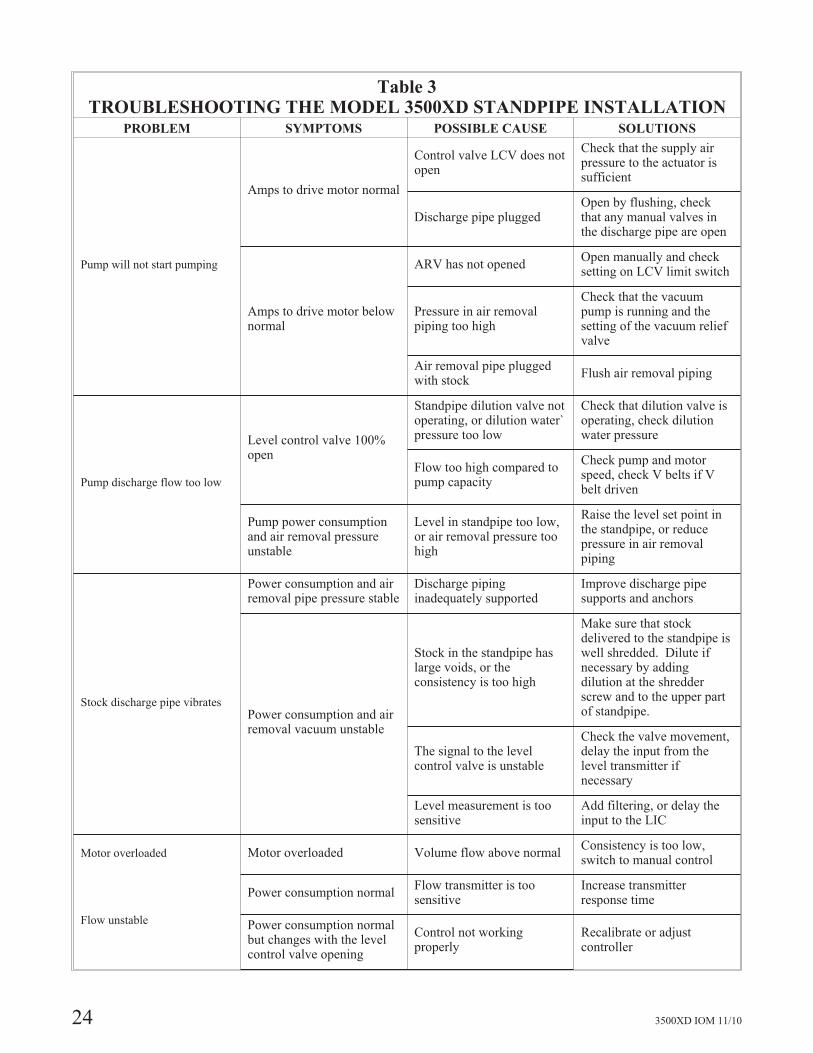
Table 3TROUBLESHOOTING THE MODEL 3500XD STANDPIPE INSTALLATION
PROBLEM SYMPTOMS POSSIBLE CAUSE SOLUTIONS
Pump will not start pumping
Amps to drive motor normal
Control valve LCV does notopen
Check that the supply airpressure to the actuator issufficient
Discharge pipe pluggedOpen by flushing, checkthat any manual valves inthe discharge pipe are open
Amps to drive motor belownormal
ARV has not openedOpen manually and checksetting on LCV limit switch
Pressure in air removalpiping too high
Check that the vacuumpump is running and thesetting of the vacuum reliefvalve
Air removal pipe pluggedwith stock
Flush air removal piping
Pump discharge flow too low
Level control valve 100%open
Standpipe dilution valve notoperating, or dilution water`pressure too low
Check that dilution valve isoperating, check dilutionwater pressure
Flow too high compared topump capacity
Check pump and motorspeed, check V belts if Vbelt driven
Pump power consumptionand air removal pressureunstable
Level in standpipe too low,or air removal pressure toohigh
Raise the level set point inthe standpipe, or reducepressure in air removalpiping
Stock discharge pipe vibrates
Power consumption and airremoval pipe pressure stable
Discharge pipinginadequately supported
Improve discharge pipesupports and anchors
Power consumption and airremoval vacuum unstable
Stock in the standpipe haslarge voids, or theconsistency is too high
Make sure that stockdelivered to the standpipe iswell shredded. Dilute ifnecessary by addingdilution at the shredderscrew and to the upper partof standpipe.
The signal to the levelcontrol valve is unstable
Check the valve movement,delay the input from thelevel transmitter ifnecessary
Level measurement is toosensitive
Add filtering, or delay theinput to the LIC
Motor overloaded Motor overloaded Volume flow above normalConsistency is too low,switch to manual control
Flow unstable
Power consumption normalFlow transmitter is toosensitive
Increase transmitterresponse time
Power consumption normalbut changes with the levelcontrol valve opening
Control not workingproperly
Recalibrate or adjustcontroller

3500XD IOM 11/10 25
MAINTENANCELUBRICATION. . . . . . . . . . . . . . . . . . . . . . . . . . . . . . . . . . . . 25
IMPELLER CLEARANCE ADJUSTMENT . . . . . . . . . . . . . . . . . . . . 26
DISASSEMBLY. . . . . . . . . . . . . . . . . . . . . . . . . . . . . . . . . . . . 27
INSPECTION AND OVERHAUL. . . . . . . . . . . . . . . . . . . . . . . . . . 31
REASSEMBLY . . . . . . . . . . . . . . . . . . . . . . . . . . . . . . . . . . . . 32
LUBRICATION
NOTE: Operation of the unit without proper lubricationwill cause bearing failure, and pump seizure.
NOTE: Pumps are shipped without oil. Oil lubricatedbearings must be lubricated at the job site.
Oil lubricated bearings must be lubricated at the job site.Remove fill plug and add oil until level is at the center of thesight glass. Replace fill plug.
Change the oil after 2000 hours for new bearings, thereafterevery 2000 operating hours or 3 months (whichever comesfirst). Change more often if oil becomes contaminated withdirt or water.
A high quality turbine oil with rust and oxidation inhibitorsshould be used. For the majority of operational conditions,bearing temperatures will run between 60° C (140° F) and82° C (180° F). In this range, an oil of ISO viscosity grade68 at 40° C (105° F) is recommended. If bearingtemperatures exceed 82° C (180° F), use of ISO viscositygrade 100 is recommended.
Table 4
Lubricating Oil Requirements
BearingTemperature
below 82°C (180° F)
BearingTemperatureabove 82° C
(180° F)
ISO Grade VG 68 VG 100
Approx.SSU at 38°C (100° F)
300 470
DIN 51517 C68 C100
Kinematicviscosity at40° C (105°F) mm2/sec
68 100
Acceptable Oils
Exxon Teresstic EP 68
Chevron GTS Oil 68
Mobil Mobil DTE 26 300 SSU@ 38° C (100° F)
Gulf Gulf Harmony 68
Phillips Magnus Oil Grade 315
Phillips MM motor oil SAE 20-20W
Phillips HDS motor oil SAE 20-20W
4
26 3500XD IOM 11/10
IMPELLER CLEARANCE ADJUSTMENT
�! WARNINGLock out driver power to prevent accidental start-up andphysical injury.
�! WARNINGBefore installation or disassembly of the coupling guardis performed, the driver must be de-energized, the drivercontroller/starter put in a locked out position and acaution tag placed at the controller/starter indicating thedisconnect. Replace coupling guard before resumingnormal operation of the pump or serious physical injurymay occur. Goulds Pumps, Inc. assumes no liability foravoiding the practice.
�! CAUTION
The impeller clearance setting procedure must befollowed. Improperly setting the clearance can result inequipment damage and heat generation casing failure.
If a gradual loss of head and/or capacity occurs, performancecan be restored by adjusting the impeller. If performancecannot be restored by adjusting the impeller, the pump shouldbe disassembled and the impeller, suction sideplate, andcasing inspected for wear.
The proper impeller clearance setting provides for equalclearance on both the front side (impeller to suctionsideplate) and the back side (repeller to stuffing box cover).Prior to setting the impeller clearance, it is first necessary tomeasure the total impeller travel (normally in the range of0.090” to 0.140”). Half of the total travel value thenbecomes the proper clearance to set the impeller off thesuction sideplate.
NOTE: If pump is equipped with a cartridge mechanicalseal, the centering tabs must be in place and tightened,and the set screw collar loosened. Failure to take thesesteps prior to adjusting the impeller clearance candamage the mechanical seal.
To adjust clearance, proceed as follows (Fig. 18):
1. Shut down pump.
2. Lock out power to driver.
3. Remove coupling guard and coupling spacer.
4. Loosen adjustment bolts and nuts (D).
5. Tighten each bolt (C) evenly while slowly rotating shaft,
until impeller just starts to rub against suction sideplate.
6. Clamp a dial indicator to the power frame, with the
button resting on the end of the shaft or against the face
of the coupling hub. Set indicator at 0.
7. Loosen bolts (C).
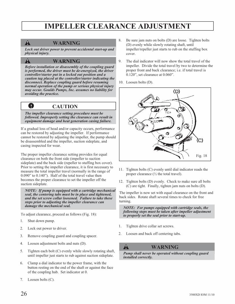
8. Be sure jam nuts on bolts (D) are loose. Tighten bolts
(D) evenly while slowly rotating shaft, until
impeller/repeller just starts to rub on the stuffing box
cover.
9. The dial indicator will now show the total travel of the
impeller. Divide the total travel by two to determine the
proper front and back clearance; i.e. if total travel is
0.120”, set clearance at 0.060”.
10. Loosen bolts (D).
11. Tighten bolts (C) evenly until dial indicator reads the
proper clearance (½ the total travel).
12. Tighten bolts (D) evenly. Check to make sure all bolts
(C) are tight. Finally, tighten jam nuts on bolts (D).
The impeller is now set with equal clearance on the front andback sides. Rotate shaft several times to check for freeturning.
NOTE: For pumps equipped with cartridge seals, thefollowing steps must be taken after impeller adjustmentto properly set the seal prior to start-up.
1. Tighten drive collar set screws.
2. Loosen and back off centering tabs.
�! WARNINGPump shall never be operated without coupling guardinstalled correctly.
Fig. 18
3500XD IOM 11/10 27
DISASSEMBLY
�! WARNINGLock out driver power to prevent accidental start-up andphysical injury.
The back pullout feature of this pump allows the completeback pullout assembly (bearing frame and rotating element)to be removed without disturbing suction or discharge pipingor driver.
The sectional and parts list contains a complete sectionalview of the pump and parts list with the proper identificationnumbers. Refer to this section as required
during maintenance procedures and when ordering spare orrepair parts.
To prepare for disassembly, proceed as follows:
1. Lock out power supply to motor.
2. Shut off all valves or equipment controlling flow to and
from the pump.
�! WARNINGLock out driver power to prevent accidental start-up andphysical injury.
�! WARNINGPump and components are heavy. Failure to properly liftand support equipment could result in serious physicalinjury or damage to pumps. Steel toed shoes must beworn at all times.
�! WARNINGOnly trained personnel should do lifting. Pumps andmotors often have integral lifting eyes or eye bolts. Theseare intended for use in lifting the individual pieces ofequipment only. Failure to properly lift equipment couldresult in serious physical injury or damage to equipment.
3. Remove all auxiliary tubing and piping.
4. Flush the pump to remove corrosive or toxic pumpage if
required.
5. Drain liquid from standpipe.
6. Disconnect coupling and remove coupling spacer (refer
to coupling instructions).
7. Drain oil.
8. If unit has stuffing box packing, remove the gland stud
nuts. The gland is in two halves and can be removed.
�! CAUTION
Never remove the back pull-out assembly unassisted,physical injury can occur.
To remove the back pullout assembly, proceed as follows:
�! WARNINGPump components can be heavy. Proper methods oflifting must be employed to avoid physical injuryand/or equipment damage. Steel toed shoes must beworn at all times.
1. Place chain or sling from crane or hoist through
frame adapter (108).
2. Remove frame foot hold-down bolts.
3. Remove bolts (370) which hold frame adapter to
casing.
4. Adjust sling tension to support back pullout
assembly.
5. Slide the back pullout assembly from the casing.
The Model 3500XD has jacking bolts (418) to assist
disassembly. Screw the jacking bolts into the tapped
holes in the frame adapter. Tighten bolts evenly, a
flat at a time, to jack back pullout assembly from
casing.
If working space is available to the side of the baseplate,the “pullout assembly” can be turned perpendicular to thebaseplate. Replace one pedestal hold-down bold inbaseplate and support the bearing frame flange withblocks. Complete disassembly of the “pullout assembly”can be accomplished on the job site. If preferred, it canbe removed to an available work area.
6. Remove casing gasket (351).
NOTE: Ensure that casing gasket is not damaged.
7. Secure shaft from rotating at the coupling end and
loosen and remove the X-Ducer nut (304). Do not
lose or damage the X-Ducer o-ring (412A).
Remove the X-Ducer (274F) from the shaft. Careful
prying may be necessary. Remove key (178B).
Remove the impeller (101) by carefully prying at the
back side at 2 points 180 degrees apart.
8. Remove impeller key (178) from the shaft.
Do not lose or damage the shaft o-rings (496B and
496C).
9. Remove the repeller (262). Do not lose or damage
the shaft o-rings (412F).
5

28 3500XD IOM 11/10
10. If unit has a mechanical seal, remove gland stud nuts.
The gland is a solid ring and cannot be removed after
unbolting. Carefully slide the gland off the gland studs
and move back on shaft and shaft sleeve. Avoid contact
with exposed lapped seal faces and keep them clean.
NOTE: Mechanical seal parts may be damaged if they oradjacent parts are handled improperly.
11. Remove the adapter to bearing frame bolts (370B) and
pull the adapter and stuffing box cover as an assembly.
Do not allow the stuffing box cover to strike the shaft,
shaft sleeve, or any mechanical seal part.
12. A cartridge mechanical seal is standard. Position and
tighten the centering tabs and loosen the drive collar set
screws. The cartridge seal can then be removed as a
unit.
13. Scribe shaft at coupling hub for proper positioning of
hub during reassembly and remove hub.
To disassemble remainder of the liquid end, casing andsuction sideplate, proceed as follows:
14. Disconnect suction and discharge flanges.
15. Remove casing hold-down bolts and move casing toward
driver. If preferred, casing can be removed from
baseplate for further disassembly.
16. Remove suction sideplates nuts (423A).
17. Remove suction sideplate (176) by tightening the three
jacking screws (370L). Be careful not to damage the
suction sideplate o-ring (412C).
To complete disassembly of power end proceed as follows:
NOTE: Bearing replacement is recommended wheneverbearings are removed from the shaft.
NOTE: Never use a hammer to drive shaft throughbearings. Severe shaft and bearing damage may occur.
18. Remove the bolts (370B) which hold the frame adapter
to the bearing frame. Remove the frame adapter (108).
19. Remove the bolts (360) which hold the inboard bearing
end cover to the frame. Remove the end cover (119A)
and labyrinth seal (125).
20. Remove bearing housing bolts (370C). Impeller
adjustment bolts with jam nuts (370D) can be used to
assist in the removal of the shaft and bearing assembly
from the bearing frame.
21. Slide the complete shaft assembly from back end of
bearing frame. (See Fig. 19) This includes the shaft,
both bearings (radial and thrust), and bearing housing.
Do not lose or damage bearing housing o-ring.
�! CAUTION
Wear insulated gloves when using a bearing heater.Bearings will get hot and can cause physical injury.
22. Using a bearing puller or a press, remove the inboard
cylindrical roller bearing (409). Be sure to apply the
removing force to the inner race of the bearing to
prevent damage to the races.
23. Be sure shaft and keyway are free of burrs and sharp
edges so labyrinth seal o-ring will not be damaged
and remove bearing end cover (109A).
24. Slide the bearing housing (134A) off shaft.
25. Straighten “tang” in lock washer (382) and remove
bearing lock nut and washer.
26. Remove coupling end bearing using a bearing puller.
Care must be taken to prevent damage to bearings.
NEVER USE A HAMMER TO DRIVE SHAFT
THROUGH BEARING. Protect bearing from
contamination.
27. The “L” group shaft is equipped with two oil flingers
(236). If the shaft is being re-used, the flingers
should not be removed, as they may be deformed
during removal. If the shaft is being replaced, new
flingers should be used.
Fig. 19

3500XD IOM 11/10 29
5
OIL LUBE
Fig. 20
Fig. 21L Group Dual Frame Coolers
30 3500XD IOM 11/10
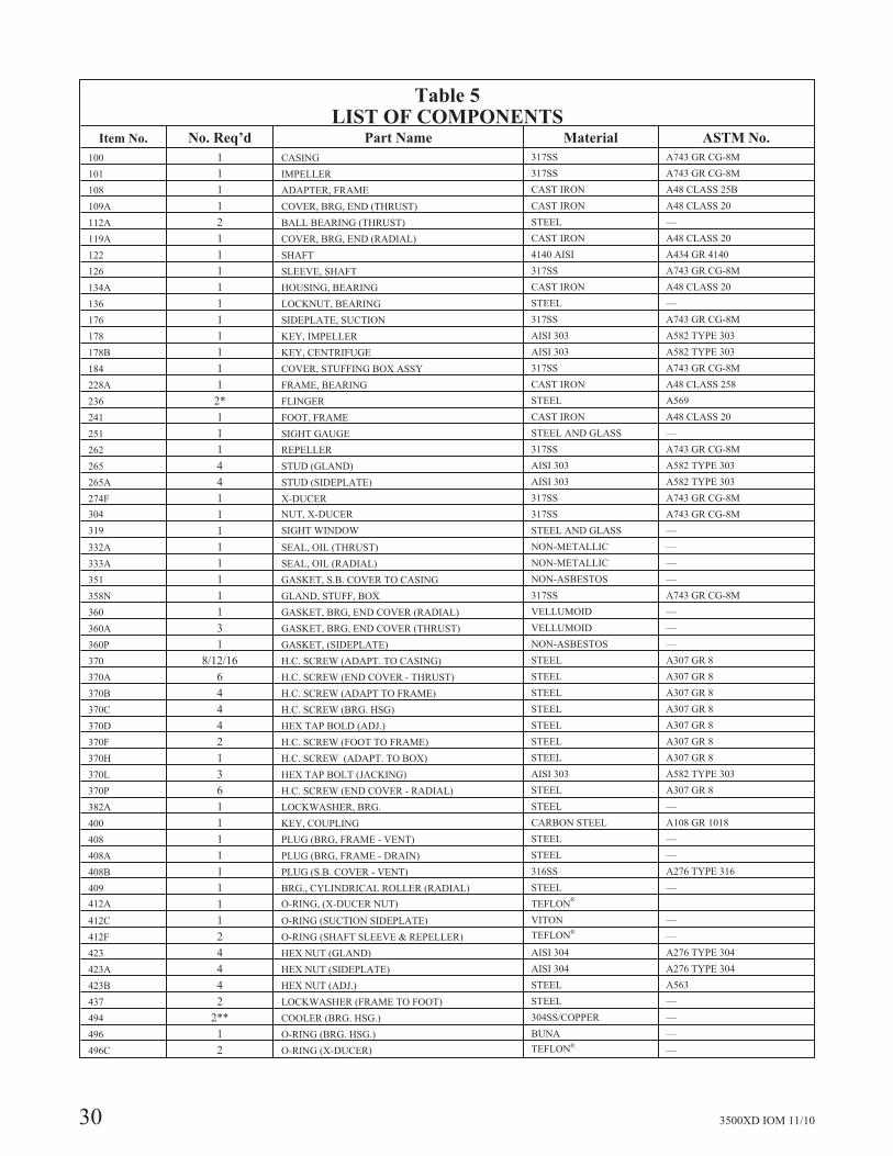
Table 5LIST OF COMPONENTS
Item No. No. Req’d Part Name Material ASTM No.
100 1 CASING 317SS A743 GR CG-8M
101 1 IMPELLER 317SS A743 GR CG-8M
108 1 ADAPTER, FRAME CAST IRON A48 CLASS 25B
109A 1 COVER, BRG, END (THRUST) CAST IRON A48 CLASS 20
112A 2 BALL BEARING (THRUST) STEEL —
119A 1 COVER, BRG, END (RADIAL) CAST IRON A48 CLASS 20
122 1 SHAFT 4140 AISI A434 GR 4140
126 1 SLEEVE, SHAFT 317SS A743 GR CG-8M
134A 1 HOUSING, BEARING CAST IRON A48 CLASS 20
136 1 LOCKNUT, BEARING STEEL —
176 1 SIDEPLATE, SUCTION 317SS A743 GR CG-8M
178 1 KEY, IMPELLER AISI 303 A582 TYPE 303
178B 1 KEY, CENTRIFUGE AISI 303 A582 TYPE 303
184 1 COVER, STUFFING BOX ASSY 317SS A743 GR CG-8M
228A 1 FRAME, BEARING CAST IRON A48 CLASS 258
236 2* FLINGER STEEL A569
241 1 FOOT, FRAME CAST IRON A48 CLASS 20
251 1 SIGHT GAUGE STEEL AND GLASS —
262 1 REPELLER 317SS A743 GR CG-8M
265 4 STUD (GLAND) AISI 303 A582 TYPE 303
265A 4 STUD (SIDEPLATE) AISI 303 A582 TYPE 303
274F 1 X-DUCER 317SS A743 GR CG-8M
304 1 NUT, X-DUCER 317SS A743 GR CG-8M
319 1 SIGHT WINDOW STEEL AND GLASS —
332A 1 SEAL, OIL (THRUST) NON-METALLIC —
333A 1 SEAL, OIL (RADIAL) NON-METALLIC —
351 1 GASKET, S.B. COVER TO CASING NON-ASBESTOS —
358N 1 GLAND, STUFF, BOX 317SS A743 GR CG-8M
360 1 GASKET, BRG, END COVER (RADIAL) VELLUMOID —
360A 3 GASKET, BRG, END COVER (THRUST) VELLUMOID —
360P 1 GASKET, (SIDEPLATE) NON-ASBESTOS —
370 8/12/16 H.C. SCREW (ADAPT. TO CASING) STEEL A307 GR 8
370A 6 H.C. SCREW (END COVER - THRUST) STEEL A307 GR 8
370B 4 H.C. SCREW (ADAPT TO FRAME) STEEL A307 GR 8
370C 4 H.C. SCREW (BRG. HSG) STEEL A307 GR 8
370D 4 HEX TAP BOLD (ADJ.) STEEL A307 GR 8
370F 2 H.C. SCREW (FOOT TO FRAME) STEEL A307 GR 8
370H 1 H.C. SCREW (ADAPT. TO BOX) STEEL A307 GR 8
370L 3 HEX TAP BOLT (JACKING) AISI 303 A582 TYPE 303
370P 6 H.C. SCREW (END COVER - RADIAL) STEEL A307 GR 8
382A 1 LOCKWASHER, BRG. STEEL —
400 1 KEY, COUPLING CARBON STEEL A108 GR 1018
408 1 PLUG (BRG, FRAME - VENT) STEEL —
408A 1 PLUG (BRG, FRAME - DRAIN) STEEL —
408B 1 PLUG (S.B. COVER - VENT) 316SS A276 TYPE 316
409 1 BRG., CYLINDRICAL ROLLER (RADIAL) STEEL —
412A 1 O-RING, (X-DUCER NUT) TEFLON®
412C 1 O-RING (SUCTION SIDEPLATE) VITON —
412F 2 O-RING (SHAFT SLEEVE & REPELLER) TEFLON®—
423 4 HEX NUT (GLAND) AISI 304 A276 TYPE 304
423A 4 HEX NUT (SIDEPLATE) AISI 304 A276 TYPE 304
423B 4 HEX NUT (ADJ.) STEEL A563
437 2 LOCKWASHER (FRAME TO FOOT) STEEL —
494 2** COOLER (BRG. HSG.) 304SS/COPPER —
496 1 O-RING (BRG. HSG.) BUNA —
496C 2 O-RING (X-DUCER) TEFLON®—
3500XD IOM 11/10 31
INSPECTION AND OVERHAUL
Impeller and Repeller
Replace if impeller, X-Ducer nut, or repeller show excessiveerosion, corrosion, extreme wear or vane breakage. O-ringgrooves must be in good condition. Check condition ofbores, as fit on shaft is critical (0.0010 to 0.0025” clearancestandard). Check impeller balance if possible (max.unbalance of 3.6 in-oz. standard).
Inducer and Centrifuge
Replace if they show excessive erosion, corrosion, orbent/broken vanes. Check condition of o-ring grooves.
Suction Sideplate
Replace if sideplate shows excessive metal loss due tocorrosion, erosion or wear.
Shaft
Check for runout to see that the shaft is not bent. Bearingseats and labyrinth seal areas must be in perfect condition andfree of scratches and grooves. O.D. and finish in these areasmust be within bearing manufacturer’s specifications. Checkthat the keyway is free of corrosion. Replace shaft ifnecessary.
Shaft Sleeve
The shaft sleeve is a push fit and is bored 0.001” to 0.003”larger than the shaft and should tap easily on the shaft. If thesleeve does not tap on easily, the bore and shaft should beinspected to see that they are free from foreign matter orburrs. The fit of the key in the keyway should also bechecked to see that it is not causing binding. The key shouldhave a sliding fit on the sides and should have clearance atthe top. Sleeve surface in stuffing box must be smooth andfree of grooves. If grooved, replace. O-ring groove must bein good condition. The original diametrical clearancebetween shaft sleeve and stuffing box bore is 0.025” to0.032”. If this clearance has increased to more than 0.050”,the shaft sleeve, and at times the stuffing box, should bereplaced.
Mechanical Seal
Lapped seal faces, gaskets, and shaft sealing members mustbe in perfect condition or excessive leakage may result.Replace worn or damaged parts.
Ball Bearings
Replace if worn, loose, rough or noisy when rotated.Replacement bearings must be of the proper size and type asspecified in the construction details (Table 6).
Labyrinth Oil Seals
Inspect and replace if o-rings are torn or otherwise damaged.
General
All parts should be clean before assembly. This is especiallyimportant at O-ring grooves, threads, lock fits, gasketsurfaces and bearing areas. Any burrs should be removedwith crocus cloth. Replace all gaskets and o-rings whenmaintenance is performed.
5
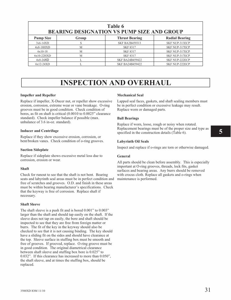
Table 6BEARING DESIGNATION VS PUMP SIZE AND GROUP
Pump Size Group Thrust Bearing Radial Bearing
3x6-14XD S SKF BA2B459313 SKF NUP-313ECP
4x8-18HXD M SKF 8317 SKF NUP-317ECP
6x10-18 M SKF 8317 SKF NUP-317ECP
6x10-22HXD M SKF 8317 SKF NUP-317ECP
4x8-24XD L SKF BA24B459422 SKF NUP-222ECP
6x12-24XD L SKF BA24B459422 SKF NUP-222ECP
32 3500XD IOM 11/10
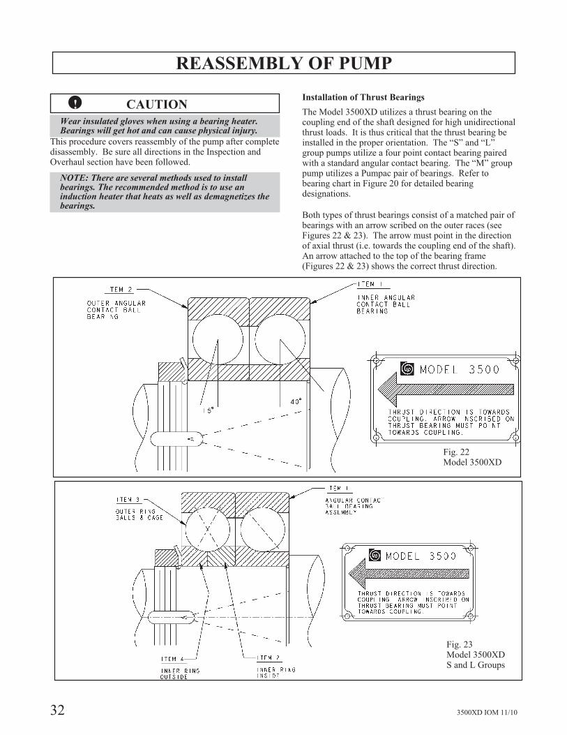
REASSEMBLY OF PUMP
�! CAUTION
Wear insulated gloves when using a bearing heater.Bearings will get hot and can cause physical injury.
This procedure covers reassembly of the pump after completedisassembly. Be sure all directions in the Inspection andOverhaul section have been followed.
NOTE: There are several methods used to installbearings. The recommended method is to use aninduction heater that heats as well as demagnetizes thebearings.
Installation of Thrust Bearings
The Model 3500XD utilizes a thrust bearing on thecoupling end of the shaft designed for high unidirectionalthrust loads. It is thus critical that the thrust bearing beinstalled in the proper orientation. The “S” and “L”group pumps utilize a four point contact bearing pairedwith a standard angular contact bearing. The “M” grouppump utilizes a Pumpac pair of bearings. Refer tobearing chart in Figure 20 for detailed bearingdesignations.
Both types of thrust bearings consist of a matched pair ofbearings with an arrow scribed on the outer races (seeFigures 22 & 23). The arrow must point in the directionof axial thrust (i.e. towards the coupling end of the shaft).An arrow attached to the top of the bearing frame(Figures 22 & 23) shows the correct thrust direction.
Fig. 22Model 3500XD
Fig. 23Model 3500XDS and L Groups
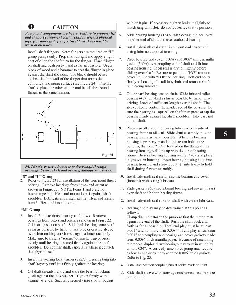
3500XD IOM 11/10 33
�! CAUTIONPump and components are heavy. Failure to properly liftand support equipment could result in serious physicalinjury or damage to pumps. Steel toed shoes must beworn at all times.
1. Install shaft flingers. Note: flingers are required on “L”
group pumps only. Prop shaft upright and apply a light
coat of oil to the shaft turn for the flinger. Place flinger
on shaft and push on by hand as far as possible. Use a
block of wood and a hammer to seat the flinger in place
against the shaft shoulder. The block should be set
against the thin wall of the flinger that forms the
cylindrical mounting surface (see Figure 24). Flip the
shaft to place the other end up and install the second
flinger in the same manner.
NOTE: Never use a hammer to drive shaft throughbearings. Severe shaft and bearing damage may occur.
“S” and “L” Group2. Refer to Figure 23 for installation of the four point thrust
bearing. Remove bearings from boxes and orient as
shown in Figure 23. NOTE: Items 1 and 3 are not
interchangeable. Heat and mount item 1 against shaft
shoulder. Lubricate and install item 2. Heat and install
item 3. Heat and install item 4.
“M” Group
2. Install Pumpac thrust bearing as follows. Remove
bearings from boxes and orient as shown in Figure 22.
Oil bearing seat on shaft. Slide both bearings onto shaft
as far as possible by hand. Place pipe or driving sleeve
over shaft making sure it rests against inner race only.
Make sure bearing is “square” on shaft. Tap or press
evenly until bearing is seated firmly against the shaft
shoulder. Do not mar shaft, especially where it contacts
the labyrinth seal.
3. Insert the bearing lock washer (382A), pressing tang into
shaft keyway until it is firmly against the bearing.
4. Oil shaft threads lightly and snug the bearing locknut
(136) against the lock washer. Tighten firmly with a
spanner wrench. Seat tang securely into slot in locknut
with drift pin. If necessary, tighten locknut slightly to
match tang with slot. do not loosen locknut to position.
5. Slide bearing housing (134A) with o-ring in place, over
impeller end of shaft and over outboard bearing.
6. Install labyrinth seal stator into thrust end cover with
o-ring lubricant applied to o-ring.
7. Place bearing end cover (109A) and .006” white manilla
gasket (360A) over coupling end of shaft and fit into
bearing housing. If oil seal is dry, oil lightly before
sliding over shaft. Be sure to position “TOP” (cast on
cover) in line with “TOP” on housing. Bolt end cover
firmly to housing. Install labyrinth seal rotor on shaft
with o-ring lubricant.
8. Oil inboard bearing seat on shaft. Slide inboard roller
bearing (409) on shaft as far as possible by hand. Place
driving sleeve of sufficient length over the shaft. The
sleeve should contact the inside race of the bearing. Be
sure the bearing is “square” on shaft then press or tap the
bearing firmly against the shaft shoulder. Take care not
to mar shaft.
9. Place a small amount of o-ring lubricant on inside of
bearing frame at oil seal. Slide shaft assembly into the
bearing frame as far as possible. When the bearing
housing is properly installed (oil return hole at the
bottom), the word “TOP” located on the flange of the
bearing housing will line up with the top of bearing
frame. Be sure bearing housing o-ring (496) is in place
in groove on housing. Insert bearing housing bolts into
bearing housing and screw about ½” into frame to hold
shaft during further assembly.
10. Install labyrinth seal stator into the bearing end cover
(inboard) with o-ring lubricant.
11. Slide gasket (360) and inboard bearing end cover (119A)
over shaft and bolt to bearing frame.
12. Install labyrinth seal rotor on shaft with o-ring lubricant.
13. Bearing end play may be determined at this point as
follows:
Clamp dial indicator to the pump so that the button rests
against the end of the shaft. Push the shaft back and
forth as far as possible. Total end play must be at least
0.001” and not more than 0.008”. If end play is less than
0.001” add coupling and bearing end cover gaskets made
form 0.006” thick manilla paper. Because of machining
tolerances, duplex thrust bearings may vary in which by
up to 0.030”. A correctly assembled pump may require
as few as one or as many as three 0.006” thick gaskets.
Refer to Fig. 25.
14. Install and position coupling hub at scribe mark on shaft.
15. Slide shaft sleeve with cartridge mechanical seal in place
on the shaft.
5
Fig. 24
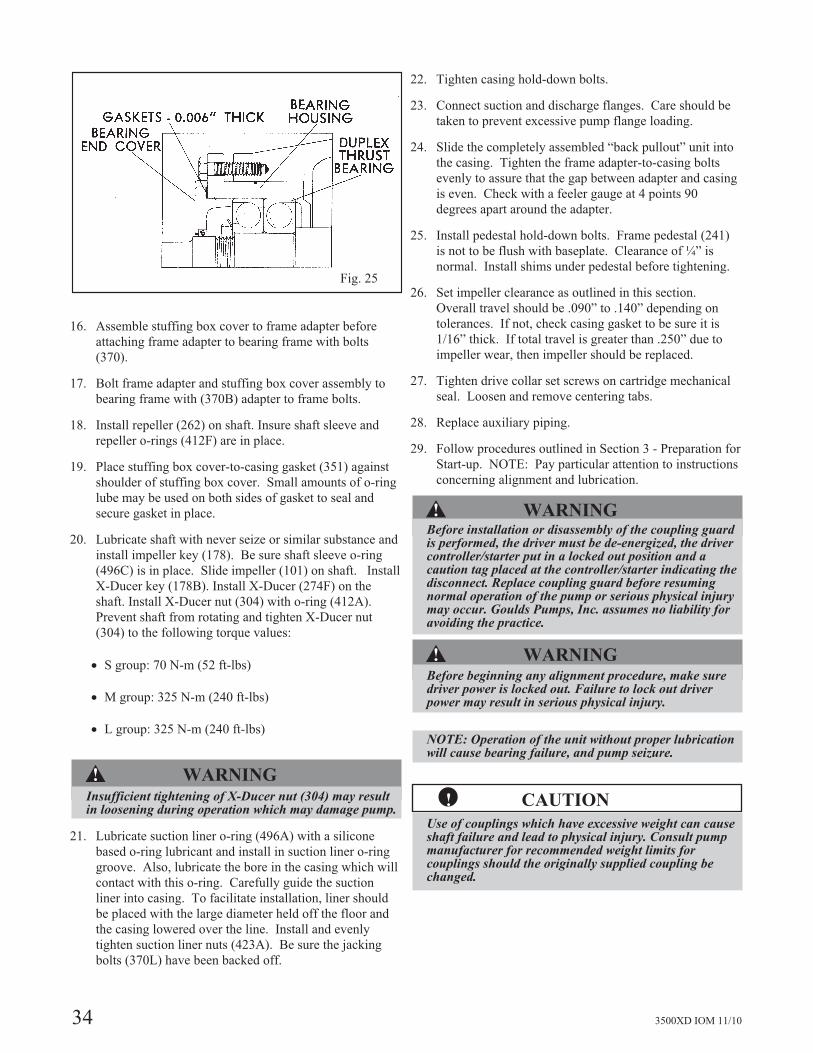
34 3500XD IOM 11/10
16. Assemble stuffing box cover to frame adapter before
attaching frame adapter to bearing frame with bolts
(370).
17. Bolt frame adapter and stuffing box cover assembly to
bearing frame with (370B) adapter to frame bolts.
18. Install repeller (262) on shaft. Insure shaft sleeve and
repeller o-rings (412F) are in place.
19. Place stuffing box cover-to-casing gasket (351) against
shoulder of stuffing box cover. Small amounts of o-ring
lube may be used on both sides of gasket to seal and
secure gasket in place.
20. Lubricate shaft with never seize or similar substance and
install impeller key (178). Be sure shaft sleeve o-ring
(496C) is in place. Slide impeller (101) on shaft. Install
X-Ducer key (178B). Install X-Ducer (274F) on the
shaft. Install X-Ducer nut (304) with o-ring (412A).
Prevent shaft from rotating and tighten X-Ducer nut
(304) to the following torque values:
� S group: 70 N-m (52 ft-lbs)
� M group: 325 N-m (240 ft-lbs)
� L group: 325 N-m (240 ft-lbs)
�! WARNINGInsufficient tightening of X-Ducer nut (304) may resultin loosening during operation which may damage pump.
21. Lubricate suction liner o-ring (496A) with a silicone
based o-ring lubricant and install in suction liner o-ring
groove. Also, lubricate the bore in the casing which will
contact with this o-ring. Carefully guide the suction
liner into casing. To facilitate installation, liner should
be placed with the large diameter held off the floor and
the casing lowered over the line. Install and evenly
tighten suction liner nuts (423A). Be sure the jacking
bolts (370L) have been backed off.
22. Tighten casing hold-down bolts.
23. Connect suction and discharge flanges. Care should be
taken to prevent excessive pump flange loading.
24. Slide the completely assembled “back pullout” unit into
the casing. Tighten the frame adapter-to-casing bolts
evenly to assure that the gap between adapter and casing
is even. Check with a feeler gauge at 4 points 90
degrees apart around the adapter.
25. Install pedestal hold-down bolts. Frame pedestal (241)
is not to be flush with baseplate. Clearance of ¼” is
normal. Install shims under pedestal before tightening.
26. Set impeller clearance as outlined in this section.
Overall travel should be .090” to .140” depending on
tolerances. If not, check casing gasket to be sure it is
1/16” thick. If total travel is greater than .250” due to
impeller wear, then impeller should be replaced.
27. Tighten drive collar set screws on cartridge mechanical
seal. Loosen and remove centering tabs.
28. Replace auxiliary piping.
29. Follow procedures outlined in Section 3 - Preparation for
Start-up. NOTE: Pay particular attention to instructions
concerning alignment and lubrication.
�! WARNINGBefore installation or disassembly of the coupling guardis performed, the driver must be de-energized, the drivercontroller/starter put in a locked out position and acaution tag placed at the controller/starter indicating thedisconnect. Replace coupling guard before resumingnormal operation of the pump or serious physical injurymay occur. Goulds Pumps, Inc. assumes no liability foravoiding the practice.
�! WARNINGBefore beginning any alignment procedure, make suredriver power is locked out. Failure to lock out driverpower may result in serious physical injury.
NOTE: Operation of the unit without proper lubricationwill cause bearing failure, and pump seizure.
�! CAUTION
Use of couplings which have excessive weight can causeshaft failure and lead to physical injury. Consult pumpmanufacturer for recommended weight limits forcouplings should the originally supplied coupling bechanged.
Fig. 25

3500XD IOM 11/10 35
HOW TO ORDER
When ordering parts call1-800-446-8537
or your local Goulds Representative
EMERGENCY SERVICE
Emergency parts service is available24 hours/day, 365 days/year ...
Call 1-800-446-8537
Visit our Web site at www.gouldspumps.com
Form No. I3500XD 11/10 © copyright 2007 Goulds Pumps, Incorporateda subsidiary of ITT Corporation