installation, operation, - aaon.com · ln series chillers and outdoor mechanical rooms...
TRANSCRIPT

LN Series
Chillers and Outdoor Mechanical Rooms
Installation Operation
amp Maintenance
FIRE OR EXPLOSION HAZARD Failure to follow safety warnings exactly could result in serious injury death or property damage Be sure to read and understand the installation operation and service instructions in this manual Improper installation adjustment alteration service or maintenance can cause serious injury death or property damage A copy of this IOM should be kept with the unit
Do not store gasoline or other flammable vapors and liquids in the vicinity of this or any other appliance WHAT TO DO IF YOU SMELL GAS Do not try to light any appliance Do not touch any electrical switch
do not use any phone in your building
Leave the building immediately Immediately call you gas supplier
from a phone remote from the building Follow the gas supplierrsquos instructions
If you cannot reach your gas supplier call the fire department
Startup and service must be performed by a Factory Trained Service Technician
WARNING WARNING
Table of Contents
AAONreg LN Series Features and Options Introduction 5
Safety 6
LN Series Feature String Nomenclature 10
General Information 15
Codes and Ordinances 15
Receiving Unit 15
Storage 16
Chiller 16
Wiring Diagrams 17
General Maintenance 17
Chiller Primary Pumping 17
Automatic Air Vent 18
Dual Pumps 18
Pressure Gauges and Thermometers 18
Pipe Insulation 18
Installation 19
Chiller Placement 19
Curb and Steel Mount Installation 19
Lifting and Handling 20
Water Connection 22
Mounting Isolation 22
Access Doors 22
End Flashing Installation 22
Low Ambient Operation 23
Electrical 23
Variable Speed Compressors 25
Startup 26
Axial Flow Condenser Fans 27
Maintenance 30
General 30
Compressors 30
Refrigerant Suction Line Filter 30
Suction Filter Removal Instructions 30
Adjusting Refrigerant Charge 31
Lubrication 34
Air-Cooled Condenser 34
Brazed Plate Heat Exchanger Cleaning 34
E-Coated Coil Cleaning 34
Microchannel Coil Cleaning 37
Service 39
Replacement Parts 39
AAON Technical Support 39
Appendix - Water Piping Component Information 40
3
Automatic Air Vent Valves 40
Pumps - Installation and Operating Instructions 42
Pump Piping - General 43
Pump Operation 44
General Care 45
Dual Pump Specific Information 47
Suction Guides 52
Flo-Trex Combination Valve 53
LN Series Startup Form 59
Maintenance Log 62
Literature Change History 63
V28980 Rev A 180627
4
Index of Tables and Figures
Tables
Table 1 - Service Clearances 19
Table 2 - Mounting Dimensions 20
Table 3- Tandem Circuited Variable Speed Compressor VFD Frequency Range 25
Table 4 - ReturnExhaust Fan Pin Location 28
Table 5 - ReturnExhaust Fan Pin Location 28
Table 6 - Fan Assembly Bushing Torque Specifications 29
Table 7 - Acceptable Refrigeration Circuit Values 32
Table 8 - R-410A Refrigerant Temperature-Pressure Chart 33
Figures
Figure 1 - LN Base 19
Figure 2 - Curb Mounting with Dimensions 20
Figure 3 - Steel Mounting Rail with Dimensions 20
Figure 4 - Lifting Points 20
Figure 5 - Lifting Detail of a 45-60 ton Unit 21
Figure 6 - Lifting Detail of a 75-140 ton Unit 21
Figure 7 - Factory Supplied End Flashings 22
Figure 8 - Front View of Utility Entry and Power Switch from Control Compartment 23
Figure 9 - Fan with the HUB on the top and RET on the bottom 27
Figure 10 - Bushing Mount Location 27
Figure 11 - RET with Pin in Groove 4 27
Figure 12 - Fan HUB and RET Castings 28
Figure 13 - Pitch Insert 29
5
AAONreg LN Series Features and Options Introduction
Energy Efficiency
High Efficiency Air-Cooled
Microchannel Condenser
Staged or Tandem VFD Controlled
Variable Speed R-410A Scroll
Compressors
Two Inch Double Wall Rigid
Polyurethane Foam Panel Construction
VFD Controlled Pumping Package
Glycol Chillers
Constant or Variable Flow Factory
Installed Pumping System
VFD Controlled Condenser Fan Head
Pressure Control
Factory Installed EXVs
Outdoor Mechanical Room
Lighted Service Compartment
Shell and Tube or Brazed Plate Heat
Evaporators
Factory Engineered Primary Pumping
Package
Safety
Phase and Brownout Protection
Environmentally Friendly
R-410A Refrigerant
Installation and Maintenance
Run Test Report and Installation Manuals
Included in Controls Compartment
Color Coded Wiring Diagrams
Sight Glass
Compressors include Rubber Isolation
Mounts
Vestibule Electric Heating in Service
Compartment
Compressor Isolation Valves
Convenience Outlet
Non-fused Disconnect
Thermometers amp Pressure Gauges
System Integration
Complete System with AAON Chilled
Water Air Handling Units
Single Point Power
Glycol Chillers
Grooved End Water Piping Connections
Constant or Variable Flow Factory
Installed Pumping System
BMS Connectivity
Extended Life
2500 Hour Salt Spray Tested Exterior
Corrosion Paint
Optional 5 Year Non-Prorated
Compressor Warranty
Polymer E-Coated Condenser Coils
Exterior Cabinet Paint Exceeds 2500
Salt Spray Test
Condenser Coil Guards
6
Safety
ELECTRIC SHOCK FIRE OR EXPLOSION HAZARD Failure to follow safety warnings exactly could result in dangerous operation serious injury death or property damage Improper servicing could result in dangerous operation serious injury death or property damage Before servicing disconnect all
electrical power to the furnace More than one disconnect may be provided
When servicing controls label all wires prior to disconnecting Reconnect wires correctly
Verify proper operation after servicing Secure all doors with key-lock or nut and bolt
WARNING
Attention should be paid to the following statements
NOTE - Notes are intended to clarify the unit installation operation and maintenance
CAUTION - Caution statements are given to prevent actions that may result in equipment
damage property damage or personal injury
WARNING - Warning statements are given to prevent actions that could result in
equipment damage property damage personal injury or death
DANGER - Danger statements are given to prevent actions that will result in equipment
damage property damage severe personal injury or death
QUALIFIED INSTALLER Improper installation adjustment alteration service or maintenance can cause property damage personal injury or loss of life Startup and service must be performed by a Factory Trained Service Technician A copy of this IOM should be kept with the unit
WARNING
WHAT TO DO IF YOU SMELL GAS Do not try to turn on unit Shut off main gas supply Do not touch any electric switch Do not use any phone in the
building Never test for gas leaks with an
open flame Use a gas detection soap solution
and check all gas connections and shut off valves
CAUTION
7
FIRE EXPLOSION OR CARBON MONOXIDE POISONING HAZARD Failure to replace proper controls could result in fire explosion or carbon monoxide poisoning Failure to follow safety warnings exactly could result in serious injury death or property damage Do not store or use gasoline or other flammable vapors and liquids in the vicinity of this appliance
Electric shock hazard Before servicing shut off all electrical power to the unit including remote disconnects to avoid shock hazard or injury from rotating parts Follow proper Lockout-Tagout procedures
WARNING
VARIABLE FREQUENCY DRIVES
Do not leave VFDs unattended in hand mode or manual bypass Damage to personnel or equipment can occur if left unattended When in hand mode or manual bypass mode VFDs will not respond to controls or alarms
WARNING
WARNING
During installation testing servicing and troubleshooting of the equipment it may be necessary to work with live electrical components Only a qualified licensed electrician or individual properly trained in handling live electrical components shall perform these tasks Standard NFPA-70E an OSHA regulation requiring an Arc Flash Boundary to be field established and marked for identification of where appropriate Personal Protective Equipment (PPE) be worn should be followed
WARNING
GROUNDING REQUIRED All field installed wiring must be completed by qualified personnel Field installed wiring must comply with NECCEC local and state electrical code requirements Failure to follow code requirements could result in serious injury or death Provide proper unit ground in accordance with these code requirements
WARNING
Electric motor over-current protection and overload protection may be a function of the Variable Frequency Drive to which the motors are wired Never defeat the VFD motor overload feature The overload ampere setting must not exceed 115 of the electric motors FLA rating as shown on the motor nameplate
CAUTION
8
PVC (Polyvinyl Chloride) and CPVC (Chlorinated Polyvinyl Chloride) are vulnerable to attack by certain chemicals Polyolester (POE) oils used with R-410A and other refrigerants even in trace amounts in a PVC or CPVC piping system will result in stress cracking of the piping and fittings and complete piping system failure
CAUTION
UNIT HANDLING To prevent injury or death lifting equipment capacity shall exceed unit weight by an adequate safety factor Always test-lift unit not more than 24 inches high to verify proper center of gravity lift point to avoid unit damage injury or death
WARNING
Door compartments containing hazardous voltage or rotating parts are equipped with door latches to allow locks Door latch are shipped with nut and bolts requiring tooled access If you do not replace the shipping hardware with a pad lock always re-install the nut amp bolt after closing the door
CAUTION
Rotation must be checked on all MOTORS AND COMPRESSORS of 3 phase units at startup by a qualified service technician Scroll compressors are directional and can be damaged if rotated in the wrong direction Compressor rotation must be checked using suction and discharge gauges Fan motor rotation should be checked for proper operation Alterations should only be made at the unit power connection
CAUTION
Do not use oxygen acetylene or air in place of refrigerant and dry nitrogen for leak testing A violent explosion may result causing injury or death
WARNING
To prevent damage to the unit do not use acidic chemical coil cleaners Use alkaline chemical coil cleaners with a pH value of 5-9 after mixing without first using an aluminum corrosion inhibitor in the cleaning solution
CAUTION
9
1 Startup and service must be performed by
a Factory Trained Service Technician
2 The unit is for outdoor use only See
General Information section for more
information
3 Every unit has a unique equipment
nameplate with electrical operational
and unit clearance specifications Always
refer to the unit nameplate for specific
ratings unique to the model you have
purchased
4 READ THE ENTIRE INSTALLATION
OPERATION AND MAINTENANCE
MANUAL OTHER IMPORTANT
SAFETY PRECAUTIONS ARE
PROVIDED THROUGHOUT THIS
MANUAL
5 Keep this manual and all literature
safeguarded near or on the unit
Some chemical coil cleaning compounds are caustic or toxic Use these substances only in accordance with the manufacturerrsquos usage instructions Failure to follow instructions may result in equipment damage injury or death
WARNING
Do not clean DX refrigerant coils with hot water or steam The use of hot water or steam on refrigerant coils will cause high pressure inside the coil tubing and damage to the coil
CAUTION
Polyolester (POE) and Polyvinylether (PVE) oils are two types of lubricants used in hydrofluorocarbon (HFC) refrigeration systems Refer to the compressor label for the proper compressor lubricant type
CAUTION
COMPRESSOR CYCLING
3 MINUTE MINIMUM OFF TIME To prevent motor overheating compressors must cycle off for a minimum of 3 minutes
3 MINUTE MINIMUM ON TIME To maintain the proper oil level compressors must cycle on for a minimum of 3 minutes The cycle rate must not exceed 6 starts per hour
WARNING
10
LN Series Feature String Nomenclature
Model Options Unit Feature Options
GE
N
MJ
RE
V
SIZ
E
SE
RIE
S
MN
RE
V
VL
T
A1
A2
A3
A4
A5
B1
B2
B3
B4
1
2
3A
3B
3C
3D
4A
4B
4C
4D
5A
5B
5C
5D
6
7
8A
8B
8C
9
10A
10B
10C
10D
LN A ndash 140 ndash C ndash A ndash 3 ndash F A C 0 E ndash 0 0 0 0 A 0 ndash 0 0 0 0 ndash 0 0 0 0 ndash 0 0 0 0 ndash 0 0 ndash 0 0 0 ndash 0 ndash 0 E 0 0 ndash
0 0 0 0 0 ndash 0 A 0 0 0 ndash 0 0 0 0 0 ndash 0 0 0 0 0 0 ndash 0 0 0 0 0 ndash 0 0 0 B
11
12
13
14
15
16
17
18
19
20
21
22
23
24
25
26A
26B
26C
26D
26E
26F
27
28
29
30
31
32
33
34
35
MODEL OPTIONS SERIES AND GENERATION
LN
MAJOR REVISION
A
UNIT SIZE
045 = 45 ton Capacity
055 = 55 ton Capacity
060 = 60 ton Capacity
075 = 75 ton Capacity
095 = 95 ton Capacity
105 = 105 ton Capacity
120 = 120 ton Capacity
140 = 140 ton Capacity
SERIES
A = 45-60 ton units
B = 75 ton unit
C = 95-140 ton units
MINOR REVISION
A
VOLTAGE
2 = 230V3Φ60Hz
3 = 460V3Φ60Hz
4 = 575V3Φ60Hz
8 = 208V3Φ60Hz
A1 COMPRESSOR STYLE
F = R-410A Tandem VFD Compatible Scroll
Compressor
A2 CONDENSER STYLE
A = Air-Cooled Microchannel Condenser
A3 EVAPORATOR CONFIGURATION
A = Standard Brazed Plate Constant Flow
B = Oversized Brazed Plate Constant Flow
C = Standard Shell amp Tube Constant Flow
D = Oversized Shell amp Tube Constant Flow
A4 COATING
0 = Standard
E = Polymer E-Coated Condenser Coil
A5 STAGING
0 = Staged Compressors
E = All Circuits with Variable Capacity Compressors
- 2 Circuits
G = Half Circuits with Variable Capacity
Compressors - 2 Circuits
B1 BLANK
0 = Standard
B2 BLANK
0 = Standard
B3 BLANK
0 = Standard
B4 BLANK
0 = Standard
UNIT FEATURE OPTIONS 1 UNIT ORIENTATION
A = Standard Access Left Water Connections
B = Standard Access Right Water Connections
C = Standard Access Bottom Water Connections
2 PUMPING STYLE
0 = No Pumps
B = Constant Flow Primary Pumping System - Large
Pipe Size
D = Variable Flow Primary Pumping System - Large
Pipe Size
11
LN Series Feature String Nomenclature
Model Options Unit Feature Options
GE
N
MJR
EV
S
IZE
SE
RIE
S
MN
RE
V
VL
T
A1
A2
A3
A4
A5
B1
B2
B3
B4
1
2 3A
3B
3C
3D
4A
4B
4C
4D
5A
5B
5C
5D
6
7
8A
8B
8C
9
10A
10B
10C
10D
LN A ndash 140 ndash C ndash A ndash 3 ndash F A C 0 E ndash 0 0 0 0 A 0 ndash 0 0 0 0 ndash 0 0 0 0 ndash 0 0 0 0 ndash 0 0 ndash 0 0 0 ndash 0 ndash 0 E 0 0 ndash
0 0 0 0 0 ndash 0 A 0 0 0 ndash 0 0 0 0 0 ndash 0 0 0 0 0 0 ndash 0 0 0 0 0 ndash 0 0 0 B
11
12
13
14
15
16
17
18
19
20
21
22
23
24
25
26A
26B
26C
26D
26E
26F
27
28
29
30
31
32
33
34
35
3A BUILDING PUMP CONFIGURATION
0 = No Building Pumps
A = 1 Pump + High Eff Motor
B = 1 Dual Pump + High Eff Motors
D = 1 Pump + VFD + High Eff Motor
E = 1 Dual Pump + 2 VFDs + High Eff Motors
K = 1 Pump + Field Installed VFD + High Eff Motor
L = 1 Dual Pump + 2 Field Installed VFDs + High
Eff Motors
3B BUILDING PUMP SERIES AND RPM
0 = No Building Pumps
A = 4360 (1170 nominal rpm)
B = 4360 (1760 nominal rpm)
C = 4360 (3520 nominal rpm)
D = 4380 (1170 nominal rpm)
E = 4380 (1760 nominal rpm)
F = 4380 (3520 nominal rpm)
K = 4382 (1170 nominal rpm)
L = 4382 (1760 nominal rpm)
M = 4382 (3520 nominal rpm)
3C PUMP SIZE
0 = No Building Pumps
A = 15B
B = 2B
C = 2D
D = 3D
E = 15x15x6
F = 2x2x6
G = 3x3x6
H = 4x4x6
J = 6x6x6
K = 15x15x8
L = 2x2x8
M = 3x3x8
N = 4x4x8
P= 5x5x8
Q = 6x6x8
R = 8x8x8
S = 2x2x10
T = 3x3x10
U = 4x4x10
V = 6x6x10
W = 8x8x10
Y = 4x4x115
Z = 5x5x115
1 = 6x6x115
2 = 8x8x115
3 = 4x4x13
4 = 6x6x13
5 = 8x8x13
12
LN Series Feature String Nomenclature
GE
N
MJR
EV
S
IZE
SE
RIE
S
MN
RE
V
VL
T
A1
A2
A3
A4
A5
B1
B2
B3
B4
1
2
3A
3B
3C
3D
4
A
4B
4C
4D
5A
5B
5C
5D
6
7
8A
8B
8C
9
1
0A
10
B
10
C
10D
LN A ndash 140 ndash C ndash A ndash 3 ndash F A C 0 E ndash 0 0 0 0 A 0 ndash 0 0 0 0 ndash 0 0 0 0 ndash 0 0 0 0 ndash 0 0 ndash 0 0 0 ndash 0 ndash 0 E 0 0 -
0 0 0 0 0 ndash 0 A 0 0 0 ndash 0 0 0 0 0 ndash 0 0 0 0 0 0 ndash 0 0 0 0 0 ndash 0 0 0 B
11
12
13
14
15
16
17
18
19
20
21
22
23
24
25
26A
26B
26C
26D
26E
26F
27
28
29
30
31
32
33
34
35
3D BUILDING PUMP MOTOR SIZE
0 = No Building Pumps
C = 1 hp
E = 2 hp
F = 3 hp
G = 5 hp
H = 75 hp
J = 10 hp
K = 15 hp
L = 20 hp
M = 25 hp
N = 30 hp
P = 40 hp
Q = 50 hp
4A BLANK
0 = Standard
4B BLANK
0 = Standard
4C BLANK
0 = Standard
4D BLANK
0 = Standard
5A BLANK
0 = Standard
5B BLANK
0 = Standard
5C BLANK
0 = Standard
5D BLANK
0 = Standard
6 REFRIGERATION OPTIONS
0 = Standard
A = Hot Gas Bypass on Non-Variable Capacity
Circuits
B = Hot Gas Bypass - All Circuits
7 REFRIGERATION ACCESSORIES
0 = Standard
A = Sight Glass
B = Compressor Isolation Valves
C = Option A + B
8A UNIT DISCONNECT TYPE
0 = Standard Single Point Power Block
A = Single Point Power Non-fused Disconnect
8B DISCONNECT SIZE
0 = Power Block
N = 100 amps
R = 150 amps
U = 225 amps
V = 250 amps
Z = 400 amps
3 = 600 amps
5 = 800 amps
7 = 1200 amps
8C BLANK
0 = Standard
9 ACCESSORIES
0 = Standard
B = Phase amp Brown Out Protection
10A UNIT CONTROL SEQUENCE
0 = Standard Controls
10B UNIT CONTROL SUPPLIER
E = MCS Controls
10C CONTROL SUPPLIER OPTIONS
0 = Standard
A = Touchscreen Interface
C = Modem
G = Option A + C
Model Options Unit Feature Options
13
LN Series Feature String Nomenclature
Model Options Unit Feature Options
GE
N
MJR
EV
S
IZE
SE
RIE
S
MN
RE
V
VL
T
A1
A2
A3
A4
A5
B1
B2
B3
B4
1
2
3A
3B
3C
3D
4A
4B
4C
4D
5A
5B
5C
5D
6
7
8A
8B
8C
9
10A
10B
10C
10
D
LN A ndash 140 ndash C ndash A ndash 3 ndash F A C 0 E ndash 0 0 0 0 A 0 ndash 0 0 0 0 ndash 0 0 0 0 ndash 0 0 0 0 ndash 0 0 ndash 0 0 0 ndash 0 ndash 0 E 0 0 ndash
0 0 0 0 0 ndash 0 A 0 0 0 ndash 0 0 0 0 0 ndash 0 0 0 0 0 0 ndash 0 0 0 0 0 ndash 0 0 0 B
11
12
13
14
15
16
17
18
19
20
21
22
23
24
25
26
A
26
B
26
C
26D
26E
26F
27
28
29
30
31
32
33
34
35
10D BMS CONNECTION amp DIAGNOSTICS
0 = None
A = BACnet IP
B = BACnet MSTP
C = Modbus IP
D = Modbus RTU
E = Lontalk
H = No BMS Connection with Diagnostics
J = BACnet IP with Diagnostics
K = BACnet MSTP with Diagnostics
L = Modbus IP with Diagnostics
M = Modbus RTU with Diagnostics
N = Lontalk with Diagnostics
11 BLANK
0 = Standard
12 VESTIBULE ACCESSORIES
0 = Standard
C = Vestibule Heating (Electric)
13 MAINTENANCE ACCESSORIES
0 = Standard
A = 115VAC Convenience Outlet Factory Wired
B = 115VAC Convenience Outlet Field Wired
C = Service Lights
F = Options A + C
J = Options B + C
14 BLANK
0 = Standard
15 CODE OPTIONS
0 = Standard ETL USA Listing
A = Chicago Code
B = ETL USA + Canada Listing
16 SHIPPING SPLITS
0 = One Piece Unit
17 AIR-COOLED CHILLER ACCESSORIES
H = Cond Coil Guards + Three Phase Cond Fan
Motor + Fan Cycling- 35degF Low Ambient
J = Cond Coil Guards + VFD Cond Fan Head
Pressure Control - 0degF Low Ambient
18 BLANK
0 = Standard
19 BLANK
0 = Standard
20 BLANK
0 = Standard
21 BLANK
0 = Standard
22 BLANK
0 = Standard
23 BLANK
0 = Standard
24 CHILLER ACCESSORIES 1
0 = Standard
A = Glycol Chiller
C = Thermometers amp Pressure Gauges
G = Option A + C
25 BLANK
0 = Standard
26A BLANK
0 = Standard
26B BLANK
0 = Standard
26C BLANK
0 = Standard
14
LN Series Feature String Nomenclature
Model Options Unit Feature Options
GE
N
MJR
EV
S
IZE
SE
RIE
S
MN
RE
V
VL
T
A1
A2
A3
A4
A5
B1
B2
B3
B4
1
2
3A
3B
3C
3D
4A
4B
4C
4D
5A
5B
5C
5D
6
7
8A
8B
8C
9
10A
10B
10C
10D
LN A ndash 140 ndash C ndash A ndash 3 ndash F A C 0 E ndash 0 0 0 0 A 0 ndash 0 0 0 0 ndash 0 0 0 0 ndash 0 0 0 0 ndash 0 0 ndash 0 0 0 ndash 0 ndash 0 E 0 0 ndash
0 0 0 0 0 ndash 0 A 0 0 0 ndash 0 0 0 0 0 ndash 0 0 0 0 0 0 ndash 0 0 0 0 0 ndash 0 0 0 B
11
12
13
14
15
16
17
18
19
20
21
22
23
24
25
26A
26B
26C
26
D
26
E
26
F
27
28
29
30
31
3
2
33
34
35
26D BLANK
0 = Standard
26E BLANK
0 = Standard
26F BLANK
0 = Standard
27 BLANK
0 = Standard
28 BLANK
0 = Standard
29 BLANK
0 = Standard
30 BLANK
0 = Standard
31 BLANK
0 = Standard
32 BLANK
0 = Standard
33 WARRANTY
0 = Standard Warranty
D = Compressor Warranty Years 2-5
34 CABINET MATERIAL
0 = Standard - Double Wall + R-13 Foam Insulation
35 PAINT amp SPECIAL PRICING
AUTHORIZATIONS
B = Premium AAON Gray Paint Exterior
E = Premium AAON Gray Paint Exterior + Shrink
Wrap
X = Special Pricing Authorization + Premium AAON
Gray Paint Exterior
1 = SPA + Premium AAON Gray Paint Exterior +
Shrink Wrap
4 = Special Pricing Authorization + Special Exterior
Paint Color
7 = SPA + Special Exterior Paint Color + Shrink
Wrap
15
General Information
AAON LN Series chillers are complete self-
contained liquid chilling units They are
assembled wired charged and run-tested
Models are available for air-cooled
applications Chiller primary pumping
packages are available as optional features
Codes and Ordinances
LN Series units have been tested and
certified by ETL in accordance with UL
Safety Standard 1995CSA C222 No 236
System should be sized in accordance with
the American Society of Heating
Refrigeration and Air Conditioning
Engineers Handbook
Installation of LN Series units must conform
to the ICC standards of the International
Mechanical Code the International Building
Code and local building plumbing and
waste water codes All appliances must be
electrically grounded in accordance with
local codes or in the absence of local codes
the current National Electric Code
ANSINFPA 70 or the current Canadian
Electrical Code CSA C221
Receiving Unit
When received the unit should be checked
for damage that might have occurred in
transit If damage is found it should be noted
on the carrierrsquos Freight Bill A request for
inspection by carrierrsquos agent should be made
in writing at once Nameplate should be
checked to ensure the correct model sizes and
voltages have been received to match the job
requirements
If repairs must be made to damaged goods
then the factory should be notified before any
repair action is taken in order to protect the
warranty Certain equipment alteration
repair and manipulation of equipment
without the manufacturerrsquos consent may void
the product warranty Contact AAON
Technical Support for assistance with
Improper installation adjustment alteration service or maintenance can cause property damage personal injury or loss of life Startup and service must be performed by a Factory Trained Service Technician
WARNING
The Clean Air Act of 1990 bans the intentional venting of refrigerant as of July 1 1992 Approved methods of recovery recycling or reclaiming must be followed
CAUTION
Coils and sheet metal surfaces present sharp edges and care must be taken when working with equipment
Failure to observe the following instructions will result in premature failure of your system and possible voiding of the warranty
WARNING
WARNING
16
handling damaged goods repairs and freight
claims (918) 382-6450
Storage
If installation will not occur immediately
following delivery store equipment in a dry
protected area away from construction traffic
and in the proper orientation as marked on the
packaging with all internal packaging in
place Secure all loose-shipped items
Chiller
Failure to observe the following instructions
will result in premature failure of your
system and possible voiding of the warranty
Never turn off the main power supply to the
unit except for complete shutdown When
power is cut off from the unit any
compressors using crankcase heaters cannot
prevent refrigerant migration This means the
compressor will cool down and liquid
refrigerant may accumulate in the
compressor The compressor is designed to
pump refrigerant gas and damage may occur
when power is restored if liquid enters the
compressor
Before unit operation the main power switch
must be turned on for at least 24 hours for
units with compressor crankcase heaters
This will give the crankcase heater time to
clear any liquid accumulation out of the
compressor before it is required to run
Rotation must be checked on all MOTORS AND COMPRESSORS of three phase units All motors to include and not be limited to pump motors and condenser fan motors should all be checked by a qualified service technician at startup and any wiring alteration should only be made at the unit power connection
CAUTION
Scroll compressors are directional and will be damaged by operation in the wrong direction Low pressure switches on compressors have been disconnected after factory testing Rotation should be checked by a qualified service technician at startup using suction and discharge pressure gauges and any wiring alteration should only be made at the unit power connection
CAUTION
CRANKCASE HEATER OPERATION
Units may be equipped with compressor crankcase heaters which should be energized at least 24 hours prior to cooling operation to clear any liquid refrigerant from the compressors
CAUTION
COMPRESSOR CYCLING
3 MINUTE MINIMUM OFF TIME To prevent motor overheating compressors must cycle off for a minimum of 3 minutes
3 MINUTE MINIMUM ON TIME To maintain the proper oil level compressors must cycle on for a minimum of 3 minutes The cycle rate must not exceed 6 starts per hour
WARNING
17
Never cut off the main power supply to the
unit except for complete shutdown Always
control the system from the building
management system or control panel never
at the main power supply (except for
emergency or for complete shutdown of the
system)
Scroll compressors must be on a minimum of
3 minutes and off for a minimum of 3
minutes The cycle rate must be no more than
6 starts per hour
The chiller is furnished with a pressure
differential switch that is factory installed
between the chilled water supply and return
connections This sensor must not be
bypassed since it provides a signal to the unit
controller that water flow is present in the
heat exchanger and the unit can operate
without the danger of freezing the liquid
Compressor life will be seriously shortened
by reduced lubrication and the pumping of
excessive amounts of liquid oil and liquid
refrigerant
Wiring Diagrams
A complete set of unit specific wiring
diagrams in both ladder and point-to-point
form are laminated in plastic and located
inside the control compartment door
General Maintenance
When the initial startup is made and on a
periodic schedule during operation it is
necessary to perform routine service checks
on the performance of the chiller This
includes reading and recording suction
pressures and checking for normal sub-
cooling and superheat See the air-cooled
condenser sections in this manual for specific
details
Chiller Primary Pumping
Primary pumping uses a single pump to move
water (or glycol) through the chiller barrel
and back to the building This pumping
package provides a constant or variable flow
of water to the system The pump is activated
whenever the chiller is given a run signal
Water enters the unit through the return water
piping and then travels through an air
separator to remove any air that is entrapped
in the water Following this the water flows
through a suction guide with strainer The
end of the suction guide is removable for
strainer access The strainer assembly is
composed of two parts the operational
strainer and the startup strainer (located
inside the operational strainer) which is to be
removed 24 hours after startup
The pump is installed after the suction guide
and before a combination valve (Flo-Trex)
This combination valve acts as isolation
valve check valve and flow balancing valve
The shell and tube or brazed plate evaporator
is placed after the combination valve in the
water circuit with a flow switch installed
across its inlet and outlet This flow switch
closes when the velocity is above 07 feet per
second The closing flow switch signals the
control system to indicate flow through the
heat exchanger and allow cooling to activate
as required to maintain the setpoint The
water exiting the chiller evaporator leaves the
unit through the water out connection
18
Automatic Air Vent
There is an automatic air vent installed at the
high point of the system inside the pumping
package compartment The air vent valve
must be in the proper position for operation
Ensure that the small vent cap is loosened two
turns from the closed position allowing air to
be vented from the system It is advisable to
leave the cap on to prevent impurities from
entering the valve See appendix for
additional information
Dual Pumps
When redundant pumping is required factory
installed dual pumps can be ordered A dual
pump is a pump with two independent motors
and pumps in a single casing This dual pump
has a swing split-flapper valve in the
discharge port to prevent liquid recirculation
when only one pump is operating Isolation
valves in the casing allow one pump to be
isolated and removed for service while the
other pump is still operating
The controls package will activate the pump
when the unit is given a run command If the
controls do not recognize flow in 60 seconds
the second pump will be activated and an
alarm signal will be generated If the second
pump does not activate the cooling will be
locked out See appendix for additional
information
Pressure Gauges and Thermometers
Pressure gauges and thermometers are
available as a factory installed option
Thermometers are installed on the inlet and
outlet of the unit One pressure gauge is
installed at each pump This pressure gauge
is connected in three places to the water
piping before the suction guidestrainer after
the suction guide and before the pump and
after the pump There is also a needle valve
at each of these points to isolate the pressure
To measure the pressure at any given point
open the needle valve at that point and close
the other two needle valves One gauge is
used so that the calibration of the pressure
gauge is irrelevant in the calculation of the
differential pressure
Pipe Insulation
The water piping and components on units
with pumping packages are not insulated at
the factory Insulation should be installed on
the water piping after the system has been
checked for leaks
19
Installation
Chiller Placement
The AAON LN Series is designed for
outdoor applications and mounting at ground
level or on a rooftop It must be placed on a
level and solid foundation that has been
prepared to support its weight
The placement relative to the building air
intakes and other structures must be carefully
selected Be sure to observe the dimensions
that are on the rating plate of the chiller for
operational and service clearances
Table 1 - Service Clearances
Location Unit Size
45-140 tons
Front -
(Controls Side) 72rdquo
Back 72rdquo
Ends 96rdquo
Top Unobstructed
Condenser coils and fans must be free of any
obstructions in order to start and operate
properly with a correct amount of airflow
For proper unit operation the immediate area
around condenser must remain free of debris
that may be drawn in and obstruct airflow in
the condensing section
Consideration must be given to obstruction
caused by snow accumulation when placing
the unit
Curb and Steel Mount Installation
Make openings in the roof decking large
enough to allow for water piping electrical
penetrations and workspace only Do not
make openings larger than necessary Set the
curb to coincide with the openings Make
sure curb is level
If the LN is installed on a curb use a curb cap
for the open area under the condenser section
Unit specific curb drawing is included with
job submittal See SMACNA Architectural
Sheet Metal Manual for curb installation
details
Units require rail support along all four sides
of the unit base
When installed at ground level a one-piece
concrete slab should be used with footings
that extend below the frost line Care must
also be taken to protect the coil and fins from
damage due to vandalism or other causes
If unit is elevated a field supplied catwalk is
recommended to allow access to unit service
doors
This unit ships with a curb gasket that is 1frac14rdquo
wide and 1frac12rdquo tall It is recommended that this
or another similar gasket be used between the
curb and the unit to reduce vibration from the
unit to the building
All roofing work should be performed by competent roofing contractors to avoid any possible leakage
CAUTION
Figure 1 - LN Base
20
Figure 2 - Curb Mounting with Dimensions
Figure 3 - Steel Mounting Rail with
Dimensions
Table 2 - Mounting Dimensions
Tons A B C D
45-140 142rdquo 138rdquo 134rdquo 139rdquo
Figure 2
Figure 3
Lifting and Handling
If cables or chains are used to hoist the unit
they must be the same length and care should
be taken to prevent damage to the cabinet
See Figure 5 and Figure 6 for additional
information
Before lifting unit be sure that all shipping
material has been removed from unit Secure
hooks and cables at all lifting points lugs
provided on the unit
Hoist unit to a point directly above the curb
or mounting rail Be sure that the gasket
material has been applied to the curb or
mounting rail
Carefully lower and align unit with utility and
duct openings Lower the unit until the unit
skirt fits around the curb Make sure the unit
is properly seated on the curb and is level
Figure 4 - Lifting Points
21
Figure 5 - Lifting Detail of a 45-60 ton Unit
Figure 6 - Lifting Detail of a 75-140 ton Unit
Lifting slot locations are unit specific
Unit must be rigged at all marked lifting points
22
Water Connection
Connect the supply and return water lines
The connection size is listed on the unit rating
sheet along with the designed volumetric
flow rate The maximum operating pressure
for AAON LN Series units is 125 psi
Mounting Isolation
For roof mounted applications or anytime
vibration transmission is a factor vibration
isolators may be used
Access Doors
Lockable access door is provided to the
compressor and control compartment A
separate access door is also provided to the
pumping package compartment
A light switch with service lights is provided
on the wall of the compressor and control
compartment
End Flashing Installation
On all LN Series units the cabinet width will
overhang the shipping trailer on each side
In order to secure and protect the unit during
transit the sheet metal end flashings have
been removed from the unit The slot created
at the base of each end of the unit allows the
unit to set firmly on the trailer deck
Sheet metal flashings are shipped loose with
the unit and once the unit is set into place the
flashings must be installed on each end of the
unit to complete the finished seal at the base
The flashings are unit specific and designed
to cover the slot at each end of the unit to
prevent water run-off into the curb
Failure to attach and seal the end of unit with
the flashings may result in water leakage into
the curb
Figure 7 - Factory Supplied End Flashings
PVC (Polyvinyl Chloride) and CPVC (Chlorinated Polyvinyl Chloride) are vulnerable to attack by certain chemicals Polyolester (POE) oils used with R-410A and other refrigerants even in trace amounts in a PVC or CPVC piping system will result in stress cracking of the piping and fittings and complete piping system failure
CAUTION
The chiller must be operated only with liquid flowing through the evaporators
WARNING
Installing Contractor is responsible for proper sealing of the water piping entries into the unit Failure to seal the entries may result in damage to the unit and property
CAUTION
23
Low Ambient Operation
If the chiller is ordered for a Low Ambient
application the liquid system must use a
glycol solution and the piping must be
insulated to be prepared for freezing
conditions Care must be taken in the source
of electrical power for the heating tape and
thermostat
Electrical
The single point electrical power connections
are made in the electrical control
compartment
The microprocessor control furnished with
the unit is supplied with its own power supply
factory wired to the main power of the
outdoor mechanical room
Verify the unit nameplate voltage agrees with
the power supply Connect power and control
field wiring as shown on the unit specific
wiring diagram provided with the unit
Size supply conductors based on the unit
MCA rating Supply conductors must be
rated a minimum of 167degF (75degC)
Route power and control wiring separately
through the utility entry Do not run power
and signal wires in the same conduit
Protect the branch circuit in accordance with
code requirements The unit must be
electrically grounded in accordance with
local codes or in the absence of local codes
the current National Electric Code
ANSINFPA 70 or the current Canadian
Electrical Code CSA C221
Power wiring is to the unit terminal block or
main disconnect All wiring beyond this point
has been done by the manufacturer and
cannot be modified without effecting the
units agencysafety certification
Figure 8 - Front View of Utility Entry and
Power Switch from Control Compartment
Electric shock hazard Before attempting to perform any installation service or maintenance shut off all electrical power to the unit at the disconnect switches Unit may have multiple power supplies Failure to disconnect power could result in dangerous operation serious injury death or property damage
WARNING
In order to prevent water leakage into the roof curb the factory provided sheet metal flashings MUST BE attached to the unit base to cover the shipping slots at both ends of the unit
CAUTION
24
Startup technician must check for proper
motor rotation and check fan motor amperage
listed on the motor nameplate is not
exceeded Motor overload protection may be
a function of the variable frequency drive and
must not be bypassed
Note All units are factory wired for
208230V 460V or 575V If unit is to be
connected to a 208V supply the transformer
must be rewired to 208V service For 208V
service interchange the yellow and red
conductor on the low voltage control
transformer
Red-Black for 208V
Yellow-Black for 230V
Wire control signals to the unitrsquos low voltage
terminal block located in the controls
compartment All wiring beyond this point
has been completed by the manufacturer and
cannot be modified without effecting the
unitrsquos agencysafety certification
If any factory installed wiring must be
replaced use a minimum 221degF (105degC) type
AWM insulated conductors
Supply voltage must be within the minmax
range shown on the unit nameplate Available
short circuit current should not exceed the
short circuit current rating (SCCR) shown on
the unit nameplate
Three phase voltage imbalance will cause
motor overheating and premature failure
The maximum allowable imbalance is 5
Voltage imbalance is defined as 100 times the
maximum deviation from the average voltage
divided by the average voltage
Example
(218V+237V+235V)3 = 230V then
100(230V-218V)230V = 52 which
exceeds the allowable imbalance
Check voltage imbalance at the unit
disconnect switch and at the compressor
terminal Contact your local power company
for line voltage corrections
Three phase voltage imbalance will cause motor overheating and premature failure
CAUTION
Scroll compressors are directional and will be damaged by operation in the wrong direction Low pressure switches on compressors have been disconnected after factory testing Rotation should be checked by a qualified service technician at startup using suction and discharge pressure gauges and any wiring alteration should only be made at the unit power connection
Installing Contractor is responsible for proper sealing of the electrical and gas entries into the unit Failure to seal the entries may result in damage to the unit and property
CAUTION CAUTION
25
Variable Speed Compressors
Variable speed compressors should not be
operated outside the factory determined
frequency range The factory determined
compressor VFD frequency range is given
below in Table 3
Table 3- Tandem Circuited Variable Speed
Compressor VFD Frequency Range
Model (LN-) Compressor VFD
Range (Hz)
208V 230V 460V and 575V Units
045 055 060 45-65Hz
075 45-70Hz
095 105 120 35-60 Hz
140 35-65 Hz
No variable speed compressor shall operate below 35 Hz Operating variable speed compressors outside the frequency range specified in this manual voids all warranties and may result in compressor failure
CAUTION
Rotation must be checked on all MOTORS AND COMPRESSORS of three phase units Condenser fan motors should all be checked by a qualified service technician at startup and any wiring alteration should only be made at the unit power connection Variable frequency drives are programmed to automatically rotate the fan in the correct rotation Do not rely on fans with variable frequency drives for compressor rotation
CAUTION
26
Startup (See back of the manual for startup form)
Before the startup of the chiller be sure that
the following items have been checked
1 Verify that electrical power is available to
the unit
2 Verify that any remote stopstart device
connected to the chiller controller is
requesting the chiller to start
3 Verify that liquid flow is present through
the chiller from the building
4 There should be a building load of at least
25 of the chiller capacity in order to
properly check operation
5 With the main power switch off review
the MCS Controller Manual provided
with the chiller Understand the keypad
functions how to set the leaving water
temperature setpoint and how to initiate
the Run State
Use the general check list at the top of the
startup form to make a last check that all the
components are in place water flow is
present and the power supply is energized
Using the controller keypad individually set
the outputs in ldquoManual Onrdquo to confirm relay
closure and compressor operation
Cycle through all the compressors to confirm
that all are operating within tolerance
While performing the check use the startup
form to record observations of compressor
amps and refrigerant pressures
When all is running properly place the
controller in the Run mode and observe the
system until it reaches a steady state of
operation
Note For more information on programming
the controller refer to the MCS Controller
manual provided with the chiller
Electric shock hazard Shut off all electrical power to the unit to avoid shock hazard or injury from rotating parts
WARNING
Improper installation adjustment alteration service or maintenance can cause property damage personal injury or loss of life Startup and service must be performed by a Factory Trained Service Technician
WARNING
Rotation must be checked on all MOTORS AND COMPRESSORS of three phase units All motors to include and not be limited to pump motors and condenser fan motors should all be checked by a qualified service technician at startup and any wiring alteration should only be made at the unit power connection
CAUTION
Before completing installation a complete operating cycle should be observed to verify that all components are functioning properly
CAUTION
27
Axial Flow Condenser Fans
Multi-Wing Z Series Aluminum Fan Blade
Pitch Angle Setting Instructions
1 Maintain the balance of fan
Mark the hub castings across a joint so the
fan hub can be reassembled in the same
orientation
Mark the location of any balancing weight
Balancing weight will be on the outer bolt
circle in the form of washers andor longer
bolts or an additional balancing nut
Number the blades and blade sockets so that
they are replaced into their original position
Figure 9 - Fan with the HUB on the top and
RET on the bottom
2 Determine the direction of rotation
Right R is clockwise when facing the
discharge side of the fan and Left L is
counterclockwise when facing the discharge
side of the fan
3 Determine the bushing mount location
The bushing mount is the center section of the
hub through which the fan is mounted to the
shaft and typically contains either setscrews
or a center-tapered hole where the bushing
inserts
Location A is with the bushing mount on air
inlet side of the fan
Location B is with the bushing mount on air
discharge side of the fan
Figure 10 - Bushing Mount Location
4 Determine the pin location groove
Disassemble fan on a flat surface and note in
which groove the pin is located
Figure 11 - RET with Pin in Groove 4
Bushing
Mount
A B Bushing
Mount
Bushing Bushing
1 2 3 4
28
5 Determine whether the pin is in the HUB
or RET
Figure 12 - Fan HUB and RET Castings
6 Determine the current blade pitch and the pin location for the new blades
Table 4 - ReturnExhaust Fan Pin Location
Type Bushing
Mount
Blade Pitch Angle
20deg 25deg 28deg 30deg 33deg 35deg 38deg 40deg 45deg 50deg
5Z A - RET - RET RET RET HUB HUB HUB HUB
B - HUB - HUB HUB HUB RET RET RET RET
Table 5 - ReturnExhaust Fan Pin Location
Type Rot Blade Pitch Angle
20deg 25deg 28deg 30deg 33deg 35deg 38deg 40deg 45deg 50deg
5Z R - 4 - 3 2 1 4 3 2 1
L - 1 - 2 3 4 1 2 3 4
7 Replace fan blades in the new pin
location and reassemble the fan
Replace the blades with the pin in the 1 2 3
or 4 groove position of either the HUB or
RET Assemble the fan making sure to place
the blades in their previous blade sockets to
match up the previous orientation of HUB
and RET and to replace any balancing
weights in their previous locations Tighten
bolts in a cross pattern to 5-6 ft-lbs of torque
29
Multi-Wing W Series Black Glass
Reinforced Polypropylene Fan Blade Pitch
Angle Setting Instructions
Contact the AAON parts department to
acquire the new pitch pins for the fan blades
Note original position of retaining plates
center boss and all hardware including
additional hardware used for balancing
1 Remove all the bolts and nuts
2 Determine blade rotation ndash on the concave
side of the blade is a blade marking showing
6WR 6WL 7WL 7WR or 9WR The ldquoLrdquo
and ldquoRrdquo denote the rotation of the blade
3 Replace the pitch insert in the blade root
with an insert of the desired pitch
Figure 13 - Pitch Insert
4 Replace blades to their original location
5 Replace all nuts bolts and washers on the
fan hub
6 Replace retaining plates and center boss to
original location
7 Tighten nuts and bolts to 14 ft-lbs of
torque
Fan Assembly Bushings
The fan assembly bushings should be
tightened to the specifications listed in the
following table
Table 6 - Fan Assembly Bushing Torque
Specifications
Bushing Tightening Torque
(in-lbs)
H X 1125 95
H X 1375 95
SH X 1125 108
SH X 1375 108
SD X 1125 108
SD X 1375 108
SD X 1625 108
SD X 1875 108
SK X 2125 180
30
Maintenance
General
Qualified technicians must perform routine
service checks and maintenance This
includes reading and recording the
condensing and suction pressures and
checking for normal sub-cooling and
superheat
Air-cooled chillers require maintenance
schedulesprocedures Unit specific
instructions are included in this manual
Compressors
The scroll compressors are fully hermetic and
require no maintenance except keeping the
shell clean
Refrigerant Suction Line Filter
Each refrigerant circuit contains a
replaceable core suction line filter One
month after start-up remove the filter
element
The replaceable core suction filters are
provided with pressure taps and shutoff
valves for isolation when removing the filter
For safety purposes a service manifold must
be attached prior to filter maintenance
Suction Filter Removal Instructions
1 Shut down operation of the unit
2 Close both shut-off valves to isolate
the suction filter
3 Reclaim the refrigerant from the
suction filter section
4 Remove the bolts from the suction
filter end plate
5 Remove the pleated filter assembly
Prior to filter core service a service manifold MUST BE attached to in and out pressure connections to assure no pressure exists during filter maintenance Non-compliance could result in injury or violation of EPA regulations
Service gauges MUST BE connected before operating the isolation valves for the replaceable core filter
WARNING
WARNING
31
6 Replace the suction filter end plate
and bolts
7 Evacuate the suction filter assembly
to 500 microns
8 Open both shut-off valves
Adjusting Refrigerant Charge
All AAON chillers are shipped with a full
factory charge Periodically adjusting the
charge of a system may be required
Adjusting the charge of a system in the field
must be based on determination of liquid sub-
cooling and evaporator superheat On a
system with an expansion valve liquid sub-
cooling is more representative of the charge
than evaporator superheat but both
measurements must be taken
Before Charging
Refer to the unit nameplate as a reference
when determining the proper refrigerant
charge
Unit being charged must be at or near full
load conditions before adjusting the charge
Units equipped with hot gas bypass must
have the hot gas bypass valve closed to get
the proper charge
After adding or removing charge the system
must be allowed to stabilize typically 10-15
minutes before making any other
adjustments
The type of unit and options determine the
ranges for liquid sub-cooling and evaporator
superheat Refer to Table 7 when determining
the proper sub-cooling
For units equipped with low ambient (0degF)
option see the special charging instructions at
the end of this section
Checking Liquid Sub-cooling
Measure the temperature of the liquid line as
it leaves the condenser coil
Read the gauge pressure at the liquid line
close to the point where the temperature was
taken You must use liquid line pressure as it
will vary from discharge pressure due to
condenser coil pressure drop
Convert the pressure obtained to a saturated
temperature using the appropriate refrigerant
temperature-pressure chart
Subtract the measured liquid line temperature
from the saturated temperature to determine
the liquid sub-cooling
Compare calculated sub-cooling to the table
below for the appropriate unit type and
options
The Clean Air Act of 1990 bans the intentional venting of refrigerant (CFCrsquos and HCFCrsquos) as of July 1 1992 Approved methods of recovery recycling or reclaiming must be followed Fines andor incarceration may be levied for non-compliance
CAUTION
Polyolester (POE) and Polyvinylether (PVE) oils are two types of lubricants used in hydrofluorocarbon (HFC) refrigeration systems Refer to the compressor label for the proper compressor lubricant type
CAUTION
32
Checking Evaporator Superheat
Measure the temperature of the suction line
close to the compressor
Read gauge pressure at the suction line close
to the compressor
Convert the pressure obtained to a saturated
temperature using the appropriate refrigerant
temperature-pressure chart
Subtract the saturated temperature from the
measured suction line temperature to
determine the evaporator superheat
For refrigeration systems with tandem scroll
compressors it is critical that the suction
superheat setpoint on the expansion valve is
set with one compressor running The suction
superheat should be 10-13degF with one
compressor running The suction superheat
will increase with both compressors in a
tandem running Inadequate suction
superheat can allow liquid refrigerant to
return to the compressors which will wash the
oil out of the compressor Lack of oil
lubrication will destroy a compressor Liquid
sub-cooling should be measured with both
compressors in a refrigeration system
running
Compare calculated superheat to Table 7 for
the appropriate unit type and options
Table 7 - Acceptable Refrigeration Circuit
Values
Air-Cooled Chiller with Scroll
Compressors
Sub-Cooling2 12-18degF
Superheat1 10-15degF 1 One compressor running in tandem 2 Two compressors running in tandem
Adjusting Sub-cooling and Superheat
Temperatures
The system is overcharged if the sub-cooling
temperature is too high and the evaporator is
fully loaded (low loads on the evaporator
result in increased sub-cooling) and the
evaporator superheat is within the
temperature range as shown in Table 7 (high
superheat results in increased sub-cooling)
Correct an overcharged system by reducing
the amount of refrigerant in the system to
lower the sub-cooling
The system is undercharged if the superheat
is too high and the sub-cooling is too low
Correct an undercharged system by adding
refrigerant to the system to reduce superheat
and raise sub-cooling
If the sub-cooling is correct and the superheat
is too high the expansion valve may need
adjustment to correct the superheat
Expansion valves must be adjusted to approximately 10-15degF of suction superheat Failure to have sufficient superheat will damage the compressor and void the warranty
CAUTION
DO NOT OVERCHARGE Refrigerant overcharging leads to excess refrigerant in the condenser coils resulting in elevated compressor discharge pressure
CAUTION
33
Table 8 - R-410A Refrigerant Temperature-Pressure Chart
F psig F psig F psig F psig F psig
20 783 50 1422 80 2349 110 3641 140 5401
21 800 51 1448 81 2386 111 3691 141 5470
22 818 52 1474 82 2423 112 3742 142 5539
23 836 53 1501 83 2460 113 3794 143 5609
24 854 54 1528 84 2498 114 3846 144 5679
25 872 55 1555 85 2537 115 3899 145 5751
26 891 56 1582 86 2575 116 3952 146 5823
27 910 57 1610 87 2614 117 4005 147 5896
28 929 58 1638 88 2654 118 4059 148 5969
29 949 59 1667 89 2694 119 4114 149 6044
30 968 60 1696 90 2735 120 4169 150 6119
31 988 61 1725 91 2776 121 4225
32 1009 62 1754 92 2817 122 4282
33 1029 63 1784 93 2859 123 4339
34 1050 64 1815 94 2901 124 4396
35 1071 65 1845 95 2944 125 4454
36 1092 66 1876 96 2987 126 4513
37 1114 67 1907 97 3030 127 4573
38 1136 68 1939 98 3075 128 4632
39 1158 69 1971 99 3119 129 4693
40 1181 70 2004 100 3164 130 4754
41 1203 71 2036 101 3210 131 4816
42 1227 72 2070 102 3256 132 4878
43 1250 73 2103 103 3302 133 4941
44 1274 74 2137 104 3349 134 5005
45 1298 75 2171 105 3396 135 5069
46 1322 76 2206 106 3444 136 5134
47 1347 77 2241 107 3493 137 5200
48 1372 78 2277 108 3542 138 5266
49 1397 79 2313 109 3591 139 5333
34
Lubrication
All original motors and bearings are
furnished with an original factory charge of
lubrication Certain applications require
bearings be re-lubricated periodically The
schedule will vary depending on operating
duty temperature variations or severe
atmospheric conditions
Bearings should be re-lubricated at normal
operating temperatures but not when
running
Rotate the fan shaft by hand and add only
enough grease to purge the seals DO NOT
OVERLUBRICATE
Air-Cooled Condenser
The air-cooled condenser section rejects heat
by passing outdoor air over the fin tube coils
for cooling of the hot refrigerant gas from the
compressors The heated air will discharge
from the top of the section through the axial
flow fans
The condenser coils should be inspected
yearly to ensure unrestricted airflow If the
installation has a large amount of airborne
dust or other material the condenser coils
should be cleaned according to the
microchannel coil cleaning section
Brazed Plate Heat Exchanger Cleaning
Because of a normally high degree of
turbulence in brazed plate heat exchangers
for many applications the heat exchanger
channels are self-cleaning For applications
that are not self-cleaning (ie hard water at
high temperatures etc) or applications where
additional cleaning is desired it is possible to
clean the brazed plate heat exchanger by
circulating a cleaning liquid
Use a tank with weak acid 5 phosphoric
acid (H3PO4) or if the exchanger is
frequently cleaned 5 oxalic acid (H2C2O4)
Pump the cleaning liquid through the
exchanger For optimum cleaning the
cleaning solution flow rate should be a
minimum of 15 times the normal flow rate
preferably in a back-flush mode After
cleaning the heat exchanger must be rinsed
with clean water A solution of 1-2 sodium
hydroxide (NaOH) or sodium bicarbonate
(NaHCO) before the last rinse ensures that all
acid is neutralized
E-Coated Coil Cleaning
Documented quarterly cleaning of e-coated
coils is required to maintain coating warranty
coverage
Surface loaded fibers or dirt should be
removed prior to water rinse to prevent
restriction of airflow If unable to back wash
the side of the coil opposite of the coils
entering air side then surface loaded fibers or
dirt should be removed with a vacuum
cleaner If a vacuum cleaner is not available
a soft non-metallic bristle brush may be used
In either case the tool should be applied in
the direction of the fins Coil surfaces can be
easily damaged (fin edges bent over) if the
tool is applied across the fins
Use of a water stream such as a garden hose
against a surface loaded coil will drive the
fibers dirt and salts into the coil This will
make cleaning efforts more difficult Surface
loaded fibers must be completely removed
prior to using low velocity clean water rinse
Electric shock hazard Shut off all electrical power to the unit to avoid shock hazard or injury from rotating parts
WARNING
35
Quarterly cleaning is required to maintain
warranty coverage and is essential to
maintain the life of an E-coated coil Coil
cleaning shall be part of the units regularly
scheduled maintenance procedures
Failure to clean an E-coated coil on the
prescribed quarterly cycle will void the
warranty and may result in reduced
efficiency and durability in the environment
A routine two-step quarterly coil cleaning is
required to maintain warranty
Step one is to clean the coil with the below
approved coil cleaner (see approved products
list under the Recommended Coil Cleanersrdquo
section
Step two is to use the approved saltchloride
remover under the Recommended Chloride
Removerrdquo section to dissolve soluble salts
and revitalize the unit It is very important
when cleaning andor rinsing not to exceed
130degF and potable water pressure is less than
100 psig to avoid damaging the unit and coil
fin edges
For routine quarterly cleaning first clean the
coil with the below approved coil
cleaner After cleaning the coils with the
approved cleaning agent use the approved
chloride remover to remove soluble salts and
revitalize the unit
Recommended Coil Cleaner ndash Step 1
GulfCoatTM Coil Cleaner assuming it is
used in accordance with the manufacturers
directions on the container for proper mixing
and cleaning has been approved for use on
E-coated coils to remove mold mildew dust
soot greasy residue lint and other
particulate Never use any cleaners that are
not approved
Recommended Chloride Remover ndash Step 2
CHLORRIDreg Concentrate assuming it
is used in accordance with the manufacturers
directions on the container for proper mixing
has been approved for use on E-coated coils
to remove chloridessalts amp sulfates Never
use any chloride removers that are not
approved
Warranty Protection ndash Step 1
Complete the coil cleaning following these
steps
1 Ensure that the power to the unit is off
and locked out
2 Clean the area around the unit if
needed to ensure leaves grass or
High velocity water from a pressure washer or compressed air should only be used at a very low pressure to prevent fin andor coil damages The force of the water or air jet may bend the fin edges and increase airside pressure drop Reduced unit performance or nuisance unit shutdowns may occur
Harsh chemicals household bleach or acid cleaners should not be used to clean e-coated coils These cleaners can be very difficult to rinse out of the coil and can accelerate corrosion and attack the e-coating If there is dirt below the surface of the coil use the recommended coil cleaners
CAUTION
CAUTION
36
loose debris will not be blown into the
coil
3 Remove panels or tops as required
gaining access to the coil(s) to be
cleaned
4 Using a pump up sprayer fill to the
appropriate level with potable water
and add the correct amount of
approved cleaner as per manufacture
instructions leaving room for the
pump plunger to be reinserted
NOTE Coils should always be cleaned
back flushed opposite of airflow to prevent
impacting the dirt into the coil
5 If the coils have heavy dirt fibers
grass leaves etc on the interior or
exterior face areas a vacuum and
brush should be used to remove those
surface contaminants prior to
applying cleaner The interior floor
drain tray or pan areas should also be
vacuumed
6 Apply the mixed cleaner to coil
surfaces using a pressurized pump up
sprayer maintaining a good rate of
pressure and at a medium size nozzle
spray (not a solid stream and not a
wide fan but somewhere in the
middle) Work in sectionspanels
ensuring that all areas are covered and
kept wetted
7 Apply the cleaner to unit interior air
exiting side coil surfaces first Work
in sectionspanels moving side to side
and from top to bottom
8 Generously soak coils by spraying
cleaner directly on and into the fin
pack section to be cleaned and allow
the cleaning solution to soak for 5 to
10 minutes
9 Using pressurized potable water
(lt100 psi) rinse the coils and
continue to always work in
sectionspanels Start at the top of the
coil and slowly move vertically
downward to the bottom Then
staying in the same vertical area
slowly move back up to the top where
you started Now move over slightly
overlapping the area just completed
and repeat above Continue until all
coil areas on the inside of the unit
have been rinsed
10 Complete steps 5-9 for the exterior air
entering side of the coils
11 Final rinse ndash Now complete a quick
rinse of both sides of the coil
including the headers piping u-
bends and hairpins
12 If the coil has a drain pan or unit floor
that is holding rinse water or cleaner
extra time and attention will need to
be taken in those areas to ensure a
proper rinse has been completed
Warranty Protection ndash Step 2
Complete the coil chloride (salt) removal
following these steps
1 CHLORRIDreg is a concentrate to be
used for both normal inland
applications at a 1001 mix ratio OR
for severe coastal applications 501
mix ratio with potable water (256
ounces of Chlorrid to 1 gal of water)
Using a pump up sprayer fill to the
appropriate level with potable water
and add the correct amount of
CHLORRIDreg salt remover leaving
room for the pump plunger to be
reinserted
2 Apply CHLORRIDreg to all external
coil surfaces using a pressurized
pump up sprayer maintaining a good
rate of pressure and at a medium size
nozzle spray (not a solid stream and
not a wide fan but somewhere in the
middle) Work in sectionspanels
ensuring that all areas are covered and
kept wetted
37
3 Generously soak coils by spraying
CHLORRIDreg directly on and into
the fin pack section Let stand for 5 to
10 minutes keeping the area wetted
Do not allow to dry before rinsing
4 Using pressurized potable water
(lt100 psi) rinse the CHLORRIDreg
and dissolved chloridessalts off of
the coils continuing to always work in
sectionspanels
5 Starting at the top of the coil begin
rinsing the coil from side to side until
you reach the bottom Repeat as many
times as is necessary to ensure all coil
sectionspanels have been completed
and are thoroughly rinsed
6 Reinstall all panels and tops that were
removed
Microchannel Coil Cleaning
Documented routine cleaning of
microchannel coils with factory provided e-
coating is required to maintain coating
warranty coverage See E-Coated Coil
Cleaning section
Air-cooled heat exchangers may include
microchannel coils
Cleaning microchannel coils is necessary in
all locations In some locations it may be
necessary to clean the coils more or less often
than recommended In general a condenser
coil should be cleaned at a minimum of once
a year In locations where there is commonly
debris or a condition that causes dirtgrease
build up it may be necessary to clean the coils
more often Proper procedure should be
followed at every cleaning interval Using
improper cleaning technique or incorrect
chemicals will result in coil damage system
performance fall off and potentially leaks
requiring coil replacement
Documented routine cleaning of
microchannel coils with factory provided e-
coating is required to maintain coating
warranty coverage Use the E-Coated Coil
Cleaning section for details on cleaning e-
coated coils
Field applied coil coatings are not
recommended with microchannel coils
Allowed Chemical Cleaners and Procedures
AAON recommends certain chemicals that
can be used to remove buildup of grime and
debris on the surface of microchannel coils
These chemicals have been tested for
performance and safety and are the only
chemicals that AAON will warrant as correct
for cleaning microchannel coils
There are three procedures that are outlined
below that will clean the coils effectively
without damage to the coils Use of any other
procedure or chemical may void the warranty
to the unit where the coil is installed With
all procedures make sure the unit is off
before starting
The water pressure used to clean should not
exceed 140 psi from no closer than 6 inches
from the coils and with the water aimed
perpendicular to the coils
Electric shock hazard Shut off all electrical power to the unit to avoid shock hazard or injury from rotating parts
WARNING
WARNING
38
1 Simple Green
Simple Green is available from AAON Parts
and Supply (Part T10701) and is
biodegradable with a neutral 65 pH
Recommendation is to use it at a 4 to 1 mix
Use the following procedure
1 Rinse the coil completely with water Use
a hard spray but be careful not to bend or
damage the fins A spray that is too hard
will bend the fins Spray from the fan side
of the coil
2 With a pump sprayer filled with a mix of
4 parts water to one part Simple Green
spray the air inlet face of the coil Be sure
to cover all areas of the face of the coil
3 Allow the coil to soak for 10-15 minutes
4 Rinse the coil with water as in step one
5 Repeat as necessary
2 Vinegar
This is standard white vinegar available in
gallons from most grocery stores It has a pH
of 2-3 so it is slightly acidic Use the
following procedure
1 Rinse the coil completely with water Use
a hard spray but be careful not to bend or
damage the fins A spray that is too hard
will bend the fins Spray from the fan side
of the coil
2 Use a pump sprayer filled with vinegar
(100) Spray from the face of the coil in
the same direction as the airflow Be sure
to cover all areas of the face of the coil
3 Allow the coil to soak for 10-15 minutes
4 Rinse the coil with water as in step one
5 Repeat as necessary
3 Water Flush
This procedure can be used when the only
material to cause the coil to need cleaning is
debris from plant material that has impinged
the coil face
1 Rinse the coil completely with water Use
a hard spray but be careful not to bend or
damage the fins A spray that is too hard
will bend the fins Spray from the fan side
of the coil
2 Spray and rinse the coil from the face
Application Examples
The three procedures can be used to clean
microchannel coils They will fit with the
application depending on the area In some
areas where the springsummer has a large
cottonwood bloom 3 might work fine if the
unit is installed on an office building and no
other environmental factors apply
When a unit is installed where the sprinkler
system has water being sprayed onto the
condenser coil you might have better results
using 2 Vinegar is slightly acidic and may
help with the calcium build up from drying
water This also works well when grease is
part of the inlet air to a condenser coil
Generally the best and broadest based
procedure is 1 The grease cutting effect of
the Simple Green is good for restaurant
applications
Other Coil Cleaners
There are many cleaners on the market for
condenser coils Before using any cleaner
that is not covered in this section you must
get written approval from the AAON
warranty and service department Use of
unapproved chemicals will void the
warranty
Use pressurized clean water with pressure not to exceed 140 psi Nozzle should be 6rdquo and 80deg to 90deg from coil face Failure to do so could result in coil damage
CAUTION
39
AAON testing has determined that unless a
chemical has a neutral pH (6-8) it should not
be used
Beware of any product that claims to be a
foaming cleaner The foam that is generated
is caused by a chemical reaction to the
aluminum fin material on tube and fin coils
and with the fin tube and coating material on
microchannel coils
Microchannel coils are robust in many ways
but like any component they must be treated
correctly This includes cleaning the coils
correctly to give optimal performance over
many years
Service
If the unit will not operate correctly and a
service company is required only a company
with service technicians qualified and
experienced in both refrigerant chillers and
air conditioning are permitted to service the
systems to keep warranties in effect If
assistance is required the service technician
must contact AAON
Replacement Parts
Parts for AAON equipment may be obtained
from your local AAON representative When
ordering parts reference the unit serial
number and part number
AAON Technical Support
2424 S Yukon Ave
Tulsa OK 74107
Ph (918) 382-6450
techsupportAAONcom
wwwAAONcom
Note Before calling technician should have
model and serial number of the unit available
for the service department to help answer
questions regarding the unit
40
Appendix - Water Piping Component Information
Automatic Air Vent Valves
Automatic Air Vent Valves provide
automatic air venting for hot or cold water
distribution systems These vents purge air
that may be in the water system
The vent valve utilizes a float to actuate the
valve plug which is located at the top of the
valve Once the air is displaced and the
system pressure is sustained the valve plug
seals and prevents any water from escaping
from the system
The float vent can also operate as an anti-
vacuum device since it will permit air to enter
the system when it must be drained It can
also be installed to permit the separation and
dispersal of air while fluid is actually
circulating in the system
Overview
Body and cover are brass construction
Air vent with silicone rubber seal
Impurities do not usually affect function
as maximum float line of water is always
lower than the valve seal
Float is high temperature resistant
polyethylene
Suitable for use with glycol systems
Can be disassembled for inspection and
cleaning
Operating Range
Minimum working pressure 145psi
(10 kPa)
Maximum working pressure 150psi
(10 bars)
Temperature Range 33degF ndash 240degF
(5degC ndash 116degC)
Performance
Performance curve details the quantity of air
vented by the ldquoFloat Ventrdquo according to the
pressure in the system
Note In order to get the best results in
venting air from risers use connecting pipes
41
of at least 1frasl2 diameter between the ldquoFloat
Ventrdquo valves and installation
Installation
When the air vent valve is installed as shown
the air will not be vented while the fluid is
circulating in the system but it can vent when
the system is shut off
The figure below shows the installation of the
vent valve for the venting of air while the
fluid is circulating in the system and the
required increase in pipe size in order to
obtain proper separation of air from water
The valve should be mounted only in a
vertical position as its operation is based on
the vertical movement of the float
While the air vent valve is in operation back
off the small vent cap two turns This is the
proper operating setting which will allow air
to be vented from the system It is advisable
to leave the cap on to prevent impurities from
entering the valve
Maintenance
No maintenance is normally necessary
However if the FV-4M1 is disassembled for
inspection or cleaning it is important that
when re-assembling to ensure that the spring
loaded lever properly engages under the float
collar
42
Dimensions ndash Weights
Pumps - Installation and Operating
Instructions
Introduction
This document contains specific information
regarding the safe installation operating and
maintenance of Vertical In-Line pumps and
should be read and understood by installing
operating and maintenance personnel The
equipment supplied has been designed and
constructed to be safe and without risk to
health and safety when properly installed
operated and maintained The instructions
following must be strictly adhered to If
clarification is needed on any point please
contact Armstrong quoting the equipment
serial number
Where under normal operating conditions the
limit of 68degC155degF (Restricted Zone) for
normal touch or 80degC176degF (Unrestricted
Zone) for unintentional touch may be
experienced steps should be taken to
minimize contact or warn operatorsusers that
normal operating conditions will be
exceeded In certain cases where the
temperature of the pumped liquid exceeds the
above stated temperature levels pump casing
temperatures may exceed 100degC212degF and
not withstanding pump insulation techniques
appropriate measures must be taken to
minimize risk for operating personnel
Storage
Pumps removed from service and stored
must be properly prepared to prevent
excessive rusting Pump port protection
plates must not be removed until the pump is
ready to connect to the piping Rotate the
shaft periodically (At least monthly) to keep
No Installation of this equipment should take place unless this document has been read and understood
CAUTION
43
rotating element free and bearings fully
functional
For long term storage the pump must be
placed in a vertical position in a dry
environment Internal rusting can be
prevented by removing the plugs at the top
and bottom of the casing and drain or air blow
out all water to prevent rust buildup or the
possibility of freezing Be sure to reinstall the
plugs when the unit is made operational
Rust-proofing or packing the casing with
moisture absorbing material and covering the
flanges is acceptable When returning to
service be sure to remove the drying agent
from the pump
Handling Large VIL Units
One effective way of lifting a large pumping
unit is to place lifting hooks through the
motor lifting rings or straps around the upper
part of the motor The pump and motor unit
will free-stand on the casing ribs Remove the
coupling guard and place (2) lifting straps
through the pumpmotor pedestal one on
each side of the motor shaft and secure to the
lifting device
With the straps in place using a spacer bar if
necessary to protect the motor fan cover the
whole assembly can now be lifted securely
Note Handling transportation and
installation of this equipment should only be
undertaken by trained personnel with proper
use of lifting equipment
Remove coupling guard and place lifting
straps on each side of coupling use spacer
bar if necessary to protect motor fan cover
Vertical Inline Pump Lifting Strap
Positioning
Note All split-coupled pumps contain a
tapped hole in the motor bracket above the
discharge flange for draining the well Pipe
this drain hole to a floor drain to avoid
overflow of the cavity caused by collecting
chilled water condensate or from seal failure
Pump Piping - General
The discharge valve only is to be used to
throttle pump flow not the suction valve
Care must be taken in the suction line layout
and installation as it is usually the major
source of concern in centrifugal pump
applications
Discharge valve only is to be used to throttle pump flow
Use Caution Piping may carry high temperature fluid
CAUTION
CAUTION
44
Alignment
Alignment is unnecessary on close-coupled
pumps as there is no shaft coupling
Split-coupled units are accurately aligned at
the factory prior to being shipped and do not
need re-aligning when installed
Pump Operation
Starting Pump
Ensure that the pump turns freely by hand or
with some mechanical help such as a strap
and lever on larger pumps Ensure that all
protective guarding is securely fixed in
position
The pump must be fully primed on start up
Fill the pump casing with liquid and rotate the
shaft by hand to remove any air trapped in the
impeller On split coupled units any air
trapped in the casing as the system is filled
must be removed by the manual air vent in
the seal flush line Close-coupled units are
fitted with seal flushvent lines piped to the
pump suction area When these units operate
residual air is drawn out of the pump towards
the suction piping
lsquoBumprsquo or energize the motor momentarily
and check that the rotation corresponds with
the directional arrow on the pump casing To
reverse rotation of a three phase motor
interchange any two power leads
Start the pump with the discharge valve
closed and the suction valve open and then
gradually open the discharge valve when the
motor is at operating speed The discharge
valve may be lsquocrackedrsquo or open slightly at
start up to help eliminate trapped air
When stopping the pump Close the
discharge valve and de-energize the motor
DO NOT run the pump against a closed
discharge valve for an extended period of
time (A few minutes maximum)
Star-Delta motor starters should be fitted
with electronicmechanical interlocks that
have a timed period of no more than 40
milliseconds before switching from star
(Starting) to delta (Run) connection yet allow
the motor to reach full star (Starting) speed
before switching to delta (Run)
Should the pump be noisy or vibrate on start-
up a common reason is overstated system
head Check this by calculating the pump
operating head by deducting the suction
pressure gauge value from the discharge
gauge reading Convert the result into the
units of the pump head as stated on the pump
nameplate and compare the values Should
the actual pump operating head be
significantly less than the nameplate head
value it is typically permissible to throttle the
discharge isolation valve until the actual
operating head is equal to the nameplate
value
Any noise or vibration usually disappears
The system designer or operator should be
made aware of this soon as some adjustment
may be required to the pump impeller
diameter or drive settings if applicable to
make the pump suitable for the system as
installed
Do not run pumps with discharge valve closed or under very low flow conditions
CAUTION
Check rotation arrow prior to operating the unit
CAUTION
45
Check rotation arrow prior to operating the
unit The rotation of all Vertical In-Line units
is ldquoclockwiserdquo when viewed from the drive
end (Looking from on top of behind the
motor)
General Care
Vertical In-Line pumps are built to operate
without periodic maintenance other than
motor lubrication on larger units A
systematic inspection made at regular
intervals will ensure years of trouble-free
operation giving special attention to the
following
Keep unit clean
Keep moisture refuse dust or other loose
particles away from the pump and
ventilating openings of the motor
Avoid operating the unit in overheated
surroundings (Above 100ordmF40ordmC)
Any possibility of the unit starting while
being serviced must be eliminated
If mechanical seal environmental accessories
are installed ensure water is flowing through
the sight flow indicator and that filter
cartridges are replaced as recommended
Pump Lubrication
Lubrication is not required There are no
bearings in the pump that need external
lubrication service
Large Series split-coupled units are installed
with a shaft bushing located beneath the
impeller that is lubricated from the pump
discharge This bearing is field removable for
service on the 20x20x19 size without
disturbing the motor or other major pump
components
Motor
Follow the lubrication procedures
recommended by the motor manufacturer
Many small and medium sized motors are
permanently lubricated and need no added
lubrication Generally if there are grease
fittings evident the motor needs periodic
lubrication and if there are no grease fittings
evident no periodic lubrication is required
Check the lubrication instructions supplied
with the motor for the particular frame size
indicated on the motor nameplate
Mechanical Seal
Mechanical seals require no special attention
The mechanical seal is fitted with a flush line
The seal is flushed from discharge of the
pump casing on split-coupled pumps and is
flushedvented to the suction on close
coupled pumps
The split-coupled pump is flushed from the
pump discharge because the mechanical seal
chamber is isolated from the liquid in the
pump by a throttle bushing Because the seal
chamber is isolated seal environmental
controls such as filters and separators when
installed in the split-coupled flush line are
very effective as only the seal chamber needs
cleansing and will prolong seal life in HVAC
systems
Do not run the pump unless properly filled
with water as the mechanical seals need a
film of liquid between the faces for proper
operation
Electric shock hazard Before attempting to perform any service or maintenance on pumping unit disconnect power source to the driver LOCK IT OFF and tag with the reason
WARNING
46
Mechanical seals may lsquoweeprsquo slightly at
start-up Allow the pump to continue
operating for several hours and the
mechanical seal to lsquoseatrsquo properly prior to
calling for service personnel
System Cleanliness
Before starting the pump the system must be
thoroughly cleaned flushed and drained and
replenished with clean liquid
Welding slag and other foreign materials
ldquoStop Leakrdquo and cleaning compounds and
improper or excessive water treatment are all
detrimental to the pump internals and sealing
arrangement
Proper operation cannot be guaranteed if the
above conditions are not adhered to
Note
Particular care must be taken to check the
following before the pump is put into
operation
1 Pump primed
2 Rotation OK
3 Lubrication OK
4 Pipe work properly supported
5 Voltage supply OK
6 Overload protection OK
7 Is the system clean
8 Is the area around the pump clean
Warranty
Does not cover any damages to the
equipment resulting from failure to observe
the above precautions
Noise Levels
Estimated Pumping Unit Sound Power Level Decibels A-Weighted at 1 m (3 ft) from unit
Double Check Prior to Startup
CAUTION
47
Vibration Levels
Vertical In-Line pumps are designed to meet vibration levels set by Hydraulic Institute Standard
HI Pump Vibration 964 Standard levels are as detailed below
Dual Pump Specific Information
Dual Pump Flapper Valve Operating
Instructions
This unit is fitted with internal valves to allow
isolation of one pump for service and to
automatically prevent recirculation of the
flow when only one pump is running
Procedure for Parallel or Stand-By
Pumping
Discharge and suction valve stems should be
locked in the center position This is
indicated by both locking handles in the
vertical position and the center pin of the
locking arms (4) locked by the handles This
procedure allows the discharge flapper valves
to pivot freely and locks the suction valve
firmly in the center position
Procedure for Isolation of One Side
1 Stop the pump to be serviced
2 Close and lock the suction and discharge
valves as per instructions below
3 Ensure seal flush line interconnection
valve is closed and drain the isolated
casing
4 Service isolated pump as required
Procedure for Starting the Pump after
Servicing
1 Ensure serviced pump is fully re-
assembled including all seal flush lines
and drain plugs
2 Fill the dry casing with system fluid by
opening the seal flush line
interconnecting valve and the air vent
fitting
3 Allow the pressure to equalize in the two
casings if necessary by opening seal
flush line interconnected valve
4 Unlock the discharge valve as per
instructions below
5 Unlock the suction valve as per
instructions below
NOTE Keep hands and tools away from
locked suction valve arm as the differential
pressure may cause the arm to rotate quickly
with force when unlocked
6 Close the seal flush line interconnect
valve and restart pump
Valve Operation - Refer to following 3rdquo 4rdquo
amp 6rdquo valve illustration and the 8rdquo valve
illustration
48
Discharge Valve
This valve performs the dual function of
automatically sealing the discharge of the
inactive pump when one pump is running and
can manually be closed and locked to isolate
one pump for service
Automatic Flapper Operation
In the flapper mode the two halves of the
discharge valve are free to pivot
independently under normal operating
conditions The locking handle (3) should be
secured with the set screw (11) in the vertical
position with the center pin of the locking
arm (4) trapped by the locking handle (3)
Manual Valve Locking
The locking feature of this valve is to ensure
a positive seal (leak proof) of the discharge
port on the pump to be serviced
Note Ensure the pump to be isolated is not
operating before attempting to release the
locking mechanism Failure to do so may
result in injury to the operator andor damage
to the pump
Locking
1 Loosen discharge side set screw (11) to
release the locking handle (3)
2 Rotate the discharge side locking handle
(3) so that the handle points toward the
pump to be serviced and secure in the
horizontal position using set screw (11)
This releases the discharge locking arm
(4)
3 Rotate discharge valve shaft (16) towards
the pump to be isolated The orientation
of the shaft is indicated by the center pin
on the locking arm (4)
4 Raise the locking handle (3) so that the
cam on the base of the handle forces the
pin of the locking arm (4) towards the
pump to be isolated The locking handle
(3) should be raised to between 45
degrees and the vertical position
5 Tighten set screw (11) to lock the locking
handle (3) in position
This handle should not be rotated past the
vertical position
Note Ensure the isolated pump is not
operating before attempting to release the
locking mechanism Failure to do so may
result in injury to the operator andor damage
the pump
Unlocking
1 Open the interconnecting valve on the
seal flush line to pressurize the serviced
pump and vent air through bleeder valve
on series 4302
2 Close these valves once the pressure is
equalized and air removed
3 Loosen set screw (11) and lower locking
handle (3) to the horizontal position
secure with set screw (11)
4 Rotate valve to center position so that the
center pin of the locking arm (4) locates
in the recess on the locking handle (3)
5 Loosen set screw (11) and raise locking
arm (3) to the vertical position locking
the center pin in the locking arm recess
secure with set screw (11)
Suction Valve
Manual Operation
The suction side valve is designed for use as
a manually operated isolation valve This
valve is not designed to automatically pivot
as the discharge flappers do
Locking
1 Loosen suction side set screw (11) to
release the locking handle (3)
Care should be taken when performing procedures 3 and 4 Read instructions carefully
WARNING
49
2 Rotate the suction side locking handle (3)
so that the handle points towards the
pump to be serviced and secure in the
horizontal position using set screw (11)
This releases the suction locking arm (4)
Note The locking handle (3) should only be
rotated towards the pump stopped for service
The suction valve is designed to prevent the
locking handle (1) from rotating towards the
running pump as the suction of the running
pump could cause the valve to slam shut with
sufficient force to injure the operator andor
cause damage to the pump Do not attempt to
circumvent this safety feature
3 Rotate the suction valve towards the
pump to be isolated The orientation of
the shaft is indicated by the center pin on
the locking arm (4)
4 Loosen set screw (11) and raise the
locking handle (3) so that the cam on the
base on the handle forces the pin of the
locking arm (4) towards the pump to be
isolated The locking handle (3) should be
raised to between 45 degrees and the
vertical position
This handle should not be rotated past the
vertical position
5 Tighten set screw (11) to secure the
locking handle (3) in position
Unlocking
1 Open the interconnecting valve on the
seal flush line to pressurize the serviced
pump and vent air through bleeder valve
on series 4302 Close these valves once
the pressure is equalized and air removed
2 Loosen set screw (11) and lower locking
handle (3) to the horizontal position
secure with set screw (11)
NOTE Keep hands and tools away from
suction valve locking arm when freed by
locking handle as differential pressure may
cause arm to rotate quickly with force when
unlocked
3 Rotate valve to center position so that the
center pin of the locking arm (4) is
located in the recess on the locking
handle (3)
4 Loosen set screw (11) and raise locking
arm (3) to the vertical position locking
the center pin in the locking arm recess
secure with set screw
Care should be taken when performing procedures 3 and 4 Read instructions carefully
WARNING
50
51
52
Suction Guides
Introduction
Suction Guides are designed for bolting
directly onto the suction flange of horizontal
or vertical shaft centrifugal pumps
Operating Limits
The suction guide is designed to be a four-
function fitting Each Suction Guide is a 90ordm
elbow a Pipe Strainer and a Flow Stabilizer
It may also be used as a Reducing Elbow
should the suction piping be larger than the
pump inlet
Installation
The Suction Guides may be installed in any
arrangement feasible the arrangement of the
pump flange bolt-holes
Inspection
Suction Guides are thoroughly tested and
inspected before shipment to assure they
meet with your order requirements All units
must be carefully examined upon arrival for
possible damage during transit Any evidence
of mishandling should be reported
immediately to the carrier and noted on the
freight bill
Operation
No special attention need be paid to the
Suction Guide at start-up The fitting is
stationary and will strain the pumped fluid
and stabilize the flow into the pump
automatically
Temporary strainer must be removed
following system clean up
After all debris has been removed from the
system or a maximum of 24 running hours
stop the pump and close the pump isolation
valves Drain the Suction Guide by removing
the drain plug or opening the blowdown
valve if installed
Remove the Suction Guide cover and remove
the strainer assembly from the valve body
A temporary fine-mesh start-up strainer is
tack-welded to the permanent stainless steel
strainer This temporary strainer should now
be removed from the permanent strainer The
fine-mesh strainer is designed to remove
small particulate from new piping systems
and could easily clog with debris if left in
53
place This will be detrimental to the
operation of the pump
Inspect the cover O-ring and replace if
necessary
Replace the permanent strainer into the
fitting body once the temporary strainer is
removed
Replace the cover into the body Ensuring
that the strainer is properly seated tighten the
cover bolts diagonally evenly and firmly
Flo-Trex Combination Valve
Introduction
The Flo-Trex combination valves are
designed for installation on the discharge side
of centrifugal pumps and incorporate three
functions in one valve
1 Drip-tight shut-off valve
2 Spring closure design Non-slam check
valve
3 Flow throttling valve
Armgrip Flange Adapter Installation
1 Position the two halves of the Armgrip
flange adapter on the valve body ensuring
that the lugs on each half of the flange
adapters are located between the anti-
rotation lugs on the valve body (as
shown)
Insert two bolts of specified size (Table A1)
to secure the halves of the flange adapter to
the valve body (as shown)
Table A1 Armgrip Flange Adapter Details
Valve Size
125 psi150 psi 250 psi300 psi
Ductile Iron Bolt Ductile Iron Bolt
No Size No Size
2-12 4 58 8 34
3 4 58 8 34
4 8 58 8 34
5 8 34 8 34
6 8 34 12 34
8 8 34 12 78
10 12 78 16 1
12 12 78 16 1-18
The gasket cavity should face out to the
adjoining flange
2 Lubricate the inner and outer diameter of
the gasket with the lubricant provided or
a similar non-petroleum based water
soluble grease
3 Press the gasket firmly into the flange
cavity ensuring that the sealing lip is
pointed outward When in place the
gasket should not extend beyond the end
of the pipe (as shown)
54
4 Position the adjoining flange or the pipe
to the Armgrip flange adapter and install
the remaining bolts The two locking
bolts should be tightened first in order to
position the flange correctly
Note Care should be taken to ensure that
the gasket is not pinched or bent between
flanges
5 Tighten remaining nuts evenly by
following bolting instructions so that the
flange faces remain parallel (as shown in
the figure labeled Recommended Bolt
Tightening Procedure) Flange bolts
should be tightened to 70 ft-lbs torque
minimum to assure firm metal to metal
contact When raised face flanges are
used there will be a gap between the
faces of the outer diameter
6 Flange gaskets are not interchangeable
with other mechanical pipe couplings or
flange gaskets
Recommended Bolt Tightening Procedure
Field Conversion (Straight to Angle
Pattern Valve
1 Open valve at least one complete turn
2 Remove the body bolts from valve body
using Allen Key
3 Rotate one half of the valve body 180deg
making sure the lower valve seat and O
ring stay in position Inspect the O ring
for any cuts or nicks and replace if
necessary
4 Replace body bolts and torque evenly to
70 ft-lbs
55
Flow Measurement with the valve in the
Wide Open position
Where approximate indication of flow is
acceptable the Flo-Trex valve can be used
Step 1 Measure and record the differential
pressure across the valve
Step 2 With valve in fully open position
locate the pressure differential on left hand
side of the Flo-Trex Performance Curve with
Valve in Full Open Position chart and extend
line horizontally across to valve size being
used Drop line vertically down and read flow
rate from bottom of chart
Safety glasses should be worn Probes should not be left inserted into fittings for long periods of time as leakage may result
CAUTION
56
Flow Measurement with the valve in the
throttled position
Step 1 The valve stem with its grooved rings
and positioning sleeve indicates the throttled
position of the valve
The quarter turn graduations on the sleeve
with the scribed line on the stem provide an
approximate flow measurement
Note The valve is shipped in closed
position The indicator on the plastic sleeve
is aligned with the vertical scribed line on
the stem
Step 2 Record the size of the valve and stem
position using the flow indicator scale
Calculate the percentage of valve opening
based on the number of rings at the fully open
position
Valve Size 2-12 3 4 5 6 8 10 12
Number of
Rings 5 5 6 9 10 12 18 28
(valve
fully open)
Step 3 Measure and record the differential
pressure across the valve in the throttled
position
Step 4 Locate percentage of valve opening
on the bottom scale of Inherent Flow
Characteristic Curve with Valve in Throttled
Position Project line vertically up to intersect
with the Valve Characteristic Curve and from
this point project line horizontally across to
the left of the chart and record the percentage
of maximum flow rate
Step 5 On the Flo-Trex Performance Curve
with Valve in Full Open Position locate the
differential pressure obtained in Step 3 and
project line horizontally across to intercept
with Valve Performance Curve Drop a line
vertically down to read the flow rate at the
bottom of the chart
Step 6 Calculate the flow rate of the valve in
the throttled position by multiplying the flow
rate (Step 5) by the percentage of maximum
flow rate (Step 4)
Example
Valve size 4 in
Differential pressure is 54 ft
Number of open rings is 3
From the table the number of rings for the
4in valve fully open is 6
Divide open rings by total 36 = 50
throttled
57
Example Continued
From the Flo-Trex performance curve a 4in
valve with 54 ft of pressure drop represents
a flow of 400 USgpm
From the flow characteristic curve a 4in
valve at 50 open represents 34 of
maximum flow
The approximate flow of a 4in valve with a
54 ft pressure drop when 50 throttled is
100
34) x (400 =136 USgpm
100
34) x (252 =857 Ls
Note To prevent premature valve failure
it is not recommended that the valve
operate in the throttled position with more
than 25 ft pressure differential Instead the
pump impeller should be trimmed or
valves located elsewhere in the system to
partially throttle the flow
Operation
To assure tight shut-off the valve must be
closed using a wrench with 25 to 30 ft-lbs of
torque
To assure trouble free check valve operation
and shut-off operation the valve should be
periodically opened and closed to keep valve
seat and valve disc guide stem free of buildup
of system contaminants
Repacking of Flo-Trex valve under full
system pressure
If it is necessary the stem O ring can be
changed under full system pressure
Step 1 Record the valve setting
Step 2 Turn the valve stem counterclockwise
until the valve is fully open and will not turn
any further Torque to a maximum of
45 ft-lbs This will ensure good metal to
metal contact and minimal leakage
Step 3 The valve bonnet may now be
removed There may be a slight leakage as
the metal to metal backseating does not
provide a drip-tight seal
Step 4 Clean exposed portion of valve stem
being careful not to leave scratches
Step 5 Remove and replace the O ring
gasket
Step 6 Install the valve bonnet
Step 7 Tightening the valve bonnet is
necessary to stop any leaks
Step 8 Open valve to balance set point as
recorded in Step 1
Note On valve sizes of 2-12 inch and 3
inch the full open position is 5 turns
though the valve will open to 5-12 turns
which is just back of seating of valve
Seat Replacement
Step 1 Drain the system and remove valve
from piping
Step 2 Remove the body bolts from the body
using an Allen Key
Step 3 Remove seat and O Ring O rings are
not used on valves of 8 inches or larger
Step 4 Inspect and clean O ring cavity and
install new O ring and seat Valve disc stem
should be inspected and replaced if worn
Valve stem O ring should be replaced at this
time as discussed under Repacking of Flo-
Trex section
Safety glasses should be worn
CAUTION
58
Pressure-Temperature Limits
Flo-Trex Cross Section
LN Series Startup Form
Job Name_____________________________________________
Date____________
Address____________________________________________________________________
____________________________________________________________________________
Model Number_______________________________________________________________
Serial Number___________________________________________ Tag___________
Startup Contractor____________________________________________________________
Address____________________________________________________________________
_____________________________________________________
Phone____________
Pre Startup Checklist
Installing contractor should verify the following items
1 Is there any visible shipping damage Yes No
2 Is the unit level Yes No
3 Are the unit clearances adequate for service and operation Yes No
4 Do all access doors open freely and are the handles operational Yes No
5 Have all shipping braces been removed Yes No
6 Have all electrical connections been tested for tightness Yes No
7 Does the electrical service correspond to the unit nameplate Yes No
8 On 208230V units has transformer tap been checked Yes No
9 Has overcurrent protection been installed to match the unit nameplate
requirement Yes No
10 Have all set screws on the fans been tightened Yes No
11 Do all fans rotate freely Yes No
12 Does the field water piping to the unit appear to be correct per design
parameters Yes No
Ambient Temperature
Ambient Dry Bulb Temperature ________degF
Ambient Wet Bulb Temperature ________degF
WaterGlycol System
1 Has the entire system been flushed and pressure checked Yes No
2 Have isolation valves to the chiller been installed Yes No
3 Has the entire system been filled with fluid Yes No
4 Has air been bled from the heat exchangers and piping Yes No
5 Is there a minimum load of 50 of the design load Yes No
6 Has the water piping been insulated Yes No
7 Is the glycol the proper type and concentration (NA if water) Yes No
8 What is the freeze point of the glycol (NA if water)
______________________________
Chiller Configuration
Air-Cooled Chiller
Low Ambient Control Condenser Safety Check
No Water Leaks
Water Flow ________ gpm
Chilled Water In Temperature ________degF
Chilled Water Out Temperature ________degF
CompressorsDX Cooling
Check Rotation
Number Model L1 L2 L3
Head
Pressure
PSIG
Suction
Pressure
PSIG
Crankcase
Heater
Amps
1
2
3
4
Refrigeration System 1 - Cooling Mode
Pressure Saturated
Temperature
Line
Temperature Sub-cooling Superheat
Discharge NA NA
Suction NA
Liquid NA
Refrigeration System 2 - Cooling Mode
Pressure Saturated
Temperature
Line
Temperature Sub-cooling Superheat
Discharge NA NA
Suction NA
Liquid NA
Condenser Fans
Alignment
Check Rotation
Nameplate Amps________
Number hp L1 L2 L3
1
2
3
4
5
6
7
8
Pumping Package
hp L1 L2 L3 Flow (gpm)
Chiller Building Pump 1
Chiller Building Pump 2
Maintenance Log
This log must be kept with the unit It is the responsibility of the owner andor maintenanceservice
contractor to document any service repair or adjustments AAON Service and Warranty
Departments are available to advise and provide phone help for proper operation and replacement
parts The responsibility for proper start-up maintenance and servicing of the equipment falls to
the owner and qualified licensed technician
Entry
Date
Action Taken NameTel
Literature Change History
February 2014
Initial version
July 2014
Corrected tonnages for the figures of the lifting details
January 2015
Updated cover picture and Feature 17-H minimum operation temperature
July 2015
Updated Microchannel Coil Cleaning section Updated Flo-Trex images Added Features and
Options Information
August 2016
Changed coil cleaning pressure to 100 psig
October 2017
Added picture to show the open base Added phase imbalance discussion Added frequency
ranges for VFD compressors Changed the minimum compressor cycling times to 3 minutes
Added suction line filter removal instructions
May 2018
Updated technical support contact information
June 2018
Updated E-coated coil cleaning procedure Updated Flo-Trex Combination Valve section
Minor Revision changed to ldquoArdquo because LN is now AHRI certified
AAON
2425 South Yukon Ave
Tulsa OK 74107-2728
wwwAAONcom
LN Series
Installation Operation amp
Maintenance
V28980 Rev A 180627
Factory Technical Support 918-382-6450 Note Before calling Technical Support please have the model and serial number
of the unit available
Parts For replacement parts please contact your local AAON Representative
It is the intent of AAON to provide accurate and current product information However in the
interest of product improvement AAON reserves the right to change pricing specifications
andor design of its product without notice obligation or liability
Copyright copy AAON all rights reserved throughout the world
AAONreg and AAONAIREreg are registered trademarks of AAON Inc Tulsa OK
3
Automatic Air Vent Valves 40
Pumps - Installation and Operating Instructions 42
Pump Piping - General 43
Pump Operation 44
General Care 45
Dual Pump Specific Information 47
Suction Guides 52
Flo-Trex Combination Valve 53
LN Series Startup Form 59
Maintenance Log 62
Literature Change History 63
V28980 Rev A 180627
4
Index of Tables and Figures
Tables
Table 1 - Service Clearances 19
Table 2 - Mounting Dimensions 20
Table 3- Tandem Circuited Variable Speed Compressor VFD Frequency Range 25
Table 4 - ReturnExhaust Fan Pin Location 28
Table 5 - ReturnExhaust Fan Pin Location 28
Table 6 - Fan Assembly Bushing Torque Specifications 29
Table 7 - Acceptable Refrigeration Circuit Values 32
Table 8 - R-410A Refrigerant Temperature-Pressure Chart 33
Figures
Figure 1 - LN Base 19
Figure 2 - Curb Mounting with Dimensions 20
Figure 3 - Steel Mounting Rail with Dimensions 20
Figure 4 - Lifting Points 20
Figure 5 - Lifting Detail of a 45-60 ton Unit 21
Figure 6 - Lifting Detail of a 75-140 ton Unit 21
Figure 7 - Factory Supplied End Flashings 22
Figure 8 - Front View of Utility Entry and Power Switch from Control Compartment 23
Figure 9 - Fan with the HUB on the top and RET on the bottom 27
Figure 10 - Bushing Mount Location 27
Figure 11 - RET with Pin in Groove 4 27
Figure 12 - Fan HUB and RET Castings 28
Figure 13 - Pitch Insert 29
5
AAONreg LN Series Features and Options Introduction
Energy Efficiency
High Efficiency Air-Cooled
Microchannel Condenser
Staged or Tandem VFD Controlled
Variable Speed R-410A Scroll
Compressors
Two Inch Double Wall Rigid
Polyurethane Foam Panel Construction
VFD Controlled Pumping Package
Glycol Chillers
Constant or Variable Flow Factory
Installed Pumping System
VFD Controlled Condenser Fan Head
Pressure Control
Factory Installed EXVs
Outdoor Mechanical Room
Lighted Service Compartment
Shell and Tube or Brazed Plate Heat
Evaporators
Factory Engineered Primary Pumping
Package
Safety
Phase and Brownout Protection
Environmentally Friendly
R-410A Refrigerant
Installation and Maintenance
Run Test Report and Installation Manuals
Included in Controls Compartment
Color Coded Wiring Diagrams
Sight Glass
Compressors include Rubber Isolation
Mounts
Vestibule Electric Heating in Service
Compartment
Compressor Isolation Valves
Convenience Outlet
Non-fused Disconnect
Thermometers amp Pressure Gauges
System Integration
Complete System with AAON Chilled
Water Air Handling Units
Single Point Power
Glycol Chillers
Grooved End Water Piping Connections
Constant or Variable Flow Factory
Installed Pumping System
BMS Connectivity
Extended Life
2500 Hour Salt Spray Tested Exterior
Corrosion Paint
Optional 5 Year Non-Prorated
Compressor Warranty
Polymer E-Coated Condenser Coils
Exterior Cabinet Paint Exceeds 2500
Salt Spray Test
Condenser Coil Guards
6
Safety
ELECTRIC SHOCK FIRE OR EXPLOSION HAZARD Failure to follow safety warnings exactly could result in dangerous operation serious injury death or property damage Improper servicing could result in dangerous operation serious injury death or property damage Before servicing disconnect all
electrical power to the furnace More than one disconnect may be provided
When servicing controls label all wires prior to disconnecting Reconnect wires correctly
Verify proper operation after servicing Secure all doors with key-lock or nut and bolt
WARNING
Attention should be paid to the following statements
NOTE - Notes are intended to clarify the unit installation operation and maintenance
CAUTION - Caution statements are given to prevent actions that may result in equipment
damage property damage or personal injury
WARNING - Warning statements are given to prevent actions that could result in
equipment damage property damage personal injury or death
DANGER - Danger statements are given to prevent actions that will result in equipment
damage property damage severe personal injury or death
QUALIFIED INSTALLER Improper installation adjustment alteration service or maintenance can cause property damage personal injury or loss of life Startup and service must be performed by a Factory Trained Service Technician A copy of this IOM should be kept with the unit
WARNING
WHAT TO DO IF YOU SMELL GAS Do not try to turn on unit Shut off main gas supply Do not touch any electric switch Do not use any phone in the
building Never test for gas leaks with an
open flame Use a gas detection soap solution
and check all gas connections and shut off valves
CAUTION
7
FIRE EXPLOSION OR CARBON MONOXIDE POISONING HAZARD Failure to replace proper controls could result in fire explosion or carbon monoxide poisoning Failure to follow safety warnings exactly could result in serious injury death or property damage Do not store or use gasoline or other flammable vapors and liquids in the vicinity of this appliance
Electric shock hazard Before servicing shut off all electrical power to the unit including remote disconnects to avoid shock hazard or injury from rotating parts Follow proper Lockout-Tagout procedures
WARNING
VARIABLE FREQUENCY DRIVES
Do not leave VFDs unattended in hand mode or manual bypass Damage to personnel or equipment can occur if left unattended When in hand mode or manual bypass mode VFDs will not respond to controls or alarms
WARNING
WARNING
During installation testing servicing and troubleshooting of the equipment it may be necessary to work with live electrical components Only a qualified licensed electrician or individual properly trained in handling live electrical components shall perform these tasks Standard NFPA-70E an OSHA regulation requiring an Arc Flash Boundary to be field established and marked for identification of where appropriate Personal Protective Equipment (PPE) be worn should be followed
WARNING
GROUNDING REQUIRED All field installed wiring must be completed by qualified personnel Field installed wiring must comply with NECCEC local and state electrical code requirements Failure to follow code requirements could result in serious injury or death Provide proper unit ground in accordance with these code requirements
WARNING
Electric motor over-current protection and overload protection may be a function of the Variable Frequency Drive to which the motors are wired Never defeat the VFD motor overload feature The overload ampere setting must not exceed 115 of the electric motors FLA rating as shown on the motor nameplate
CAUTION
8
PVC (Polyvinyl Chloride) and CPVC (Chlorinated Polyvinyl Chloride) are vulnerable to attack by certain chemicals Polyolester (POE) oils used with R-410A and other refrigerants even in trace amounts in a PVC or CPVC piping system will result in stress cracking of the piping and fittings and complete piping system failure
CAUTION
UNIT HANDLING To prevent injury or death lifting equipment capacity shall exceed unit weight by an adequate safety factor Always test-lift unit not more than 24 inches high to verify proper center of gravity lift point to avoid unit damage injury or death
WARNING
Door compartments containing hazardous voltage or rotating parts are equipped with door latches to allow locks Door latch are shipped with nut and bolts requiring tooled access If you do not replace the shipping hardware with a pad lock always re-install the nut amp bolt after closing the door
CAUTION
Rotation must be checked on all MOTORS AND COMPRESSORS of 3 phase units at startup by a qualified service technician Scroll compressors are directional and can be damaged if rotated in the wrong direction Compressor rotation must be checked using suction and discharge gauges Fan motor rotation should be checked for proper operation Alterations should only be made at the unit power connection
CAUTION
Do not use oxygen acetylene or air in place of refrigerant and dry nitrogen for leak testing A violent explosion may result causing injury or death
WARNING
To prevent damage to the unit do not use acidic chemical coil cleaners Use alkaline chemical coil cleaners with a pH value of 5-9 after mixing without first using an aluminum corrosion inhibitor in the cleaning solution
CAUTION
9
1 Startup and service must be performed by
a Factory Trained Service Technician
2 The unit is for outdoor use only See
General Information section for more
information
3 Every unit has a unique equipment
nameplate with electrical operational
and unit clearance specifications Always
refer to the unit nameplate for specific
ratings unique to the model you have
purchased
4 READ THE ENTIRE INSTALLATION
OPERATION AND MAINTENANCE
MANUAL OTHER IMPORTANT
SAFETY PRECAUTIONS ARE
PROVIDED THROUGHOUT THIS
MANUAL
5 Keep this manual and all literature
safeguarded near or on the unit
Some chemical coil cleaning compounds are caustic or toxic Use these substances only in accordance with the manufacturerrsquos usage instructions Failure to follow instructions may result in equipment damage injury or death
WARNING
Do not clean DX refrigerant coils with hot water or steam The use of hot water or steam on refrigerant coils will cause high pressure inside the coil tubing and damage to the coil
CAUTION
Polyolester (POE) and Polyvinylether (PVE) oils are two types of lubricants used in hydrofluorocarbon (HFC) refrigeration systems Refer to the compressor label for the proper compressor lubricant type
CAUTION
COMPRESSOR CYCLING
3 MINUTE MINIMUM OFF TIME To prevent motor overheating compressors must cycle off for a minimum of 3 minutes
3 MINUTE MINIMUM ON TIME To maintain the proper oil level compressors must cycle on for a minimum of 3 minutes The cycle rate must not exceed 6 starts per hour
WARNING
10
LN Series Feature String Nomenclature
Model Options Unit Feature Options
GE
N
MJ
RE
V
SIZ
E
SE
RIE
S
MN
RE
V
VL
T
A1
A2
A3
A4
A5
B1
B2
B3
B4
1
2
3A
3B
3C
3D
4A
4B
4C
4D
5A
5B
5C
5D
6
7
8A
8B
8C
9
10A
10B
10C
10D
LN A ndash 140 ndash C ndash A ndash 3 ndash F A C 0 E ndash 0 0 0 0 A 0 ndash 0 0 0 0 ndash 0 0 0 0 ndash 0 0 0 0 ndash 0 0 ndash 0 0 0 ndash 0 ndash 0 E 0 0 ndash
0 0 0 0 0 ndash 0 A 0 0 0 ndash 0 0 0 0 0 ndash 0 0 0 0 0 0 ndash 0 0 0 0 0 ndash 0 0 0 B
11
12
13
14
15
16
17
18
19
20
21
22
23
24
25
26A
26B
26C
26D
26E
26F
27
28
29
30
31
32
33
34
35
MODEL OPTIONS SERIES AND GENERATION
LN
MAJOR REVISION
A
UNIT SIZE
045 = 45 ton Capacity
055 = 55 ton Capacity
060 = 60 ton Capacity
075 = 75 ton Capacity
095 = 95 ton Capacity
105 = 105 ton Capacity
120 = 120 ton Capacity
140 = 140 ton Capacity
SERIES
A = 45-60 ton units
B = 75 ton unit
C = 95-140 ton units
MINOR REVISION
A
VOLTAGE
2 = 230V3Φ60Hz
3 = 460V3Φ60Hz
4 = 575V3Φ60Hz
8 = 208V3Φ60Hz
A1 COMPRESSOR STYLE
F = R-410A Tandem VFD Compatible Scroll
Compressor
A2 CONDENSER STYLE
A = Air-Cooled Microchannel Condenser
A3 EVAPORATOR CONFIGURATION
A = Standard Brazed Plate Constant Flow
B = Oversized Brazed Plate Constant Flow
C = Standard Shell amp Tube Constant Flow
D = Oversized Shell amp Tube Constant Flow
A4 COATING
0 = Standard
E = Polymer E-Coated Condenser Coil
A5 STAGING
0 = Staged Compressors
E = All Circuits with Variable Capacity Compressors
- 2 Circuits
G = Half Circuits with Variable Capacity
Compressors - 2 Circuits
B1 BLANK
0 = Standard
B2 BLANK
0 = Standard
B3 BLANK
0 = Standard
B4 BLANK
0 = Standard
UNIT FEATURE OPTIONS 1 UNIT ORIENTATION
A = Standard Access Left Water Connections
B = Standard Access Right Water Connections
C = Standard Access Bottom Water Connections
2 PUMPING STYLE
0 = No Pumps
B = Constant Flow Primary Pumping System - Large
Pipe Size
D = Variable Flow Primary Pumping System - Large
Pipe Size
11
LN Series Feature String Nomenclature
Model Options Unit Feature Options
GE
N
MJR
EV
S
IZE
SE
RIE
S
MN
RE
V
VL
T
A1
A2
A3
A4
A5
B1
B2
B3
B4
1
2 3A
3B
3C
3D
4A
4B
4C
4D
5A
5B
5C
5D
6
7
8A
8B
8C
9
10A
10B
10C
10D
LN A ndash 140 ndash C ndash A ndash 3 ndash F A C 0 E ndash 0 0 0 0 A 0 ndash 0 0 0 0 ndash 0 0 0 0 ndash 0 0 0 0 ndash 0 0 ndash 0 0 0 ndash 0 ndash 0 E 0 0 ndash
0 0 0 0 0 ndash 0 A 0 0 0 ndash 0 0 0 0 0 ndash 0 0 0 0 0 0 ndash 0 0 0 0 0 ndash 0 0 0 B
11
12
13
14
15
16
17
18
19
20
21
22
23
24
25
26A
26B
26C
26D
26E
26F
27
28
29
30
31
32
33
34
35
3A BUILDING PUMP CONFIGURATION
0 = No Building Pumps
A = 1 Pump + High Eff Motor
B = 1 Dual Pump + High Eff Motors
D = 1 Pump + VFD + High Eff Motor
E = 1 Dual Pump + 2 VFDs + High Eff Motors
K = 1 Pump + Field Installed VFD + High Eff Motor
L = 1 Dual Pump + 2 Field Installed VFDs + High
Eff Motors
3B BUILDING PUMP SERIES AND RPM
0 = No Building Pumps
A = 4360 (1170 nominal rpm)
B = 4360 (1760 nominal rpm)
C = 4360 (3520 nominal rpm)
D = 4380 (1170 nominal rpm)
E = 4380 (1760 nominal rpm)
F = 4380 (3520 nominal rpm)
K = 4382 (1170 nominal rpm)
L = 4382 (1760 nominal rpm)
M = 4382 (3520 nominal rpm)
3C PUMP SIZE
0 = No Building Pumps
A = 15B
B = 2B
C = 2D
D = 3D
E = 15x15x6
F = 2x2x6
G = 3x3x6
H = 4x4x6
J = 6x6x6
K = 15x15x8
L = 2x2x8
M = 3x3x8
N = 4x4x8
P= 5x5x8
Q = 6x6x8
R = 8x8x8
S = 2x2x10
T = 3x3x10
U = 4x4x10
V = 6x6x10
W = 8x8x10
Y = 4x4x115
Z = 5x5x115
1 = 6x6x115
2 = 8x8x115
3 = 4x4x13
4 = 6x6x13
5 = 8x8x13
12
LN Series Feature String Nomenclature
GE
N
MJR
EV
S
IZE
SE
RIE
S
MN
RE
V
VL
T
A1
A2
A3
A4
A5
B1
B2
B3
B4
1
2
3A
3B
3C
3D
4
A
4B
4C
4D
5A
5B
5C
5D
6
7
8A
8B
8C
9
1
0A
10
B
10
C
10D
LN A ndash 140 ndash C ndash A ndash 3 ndash F A C 0 E ndash 0 0 0 0 A 0 ndash 0 0 0 0 ndash 0 0 0 0 ndash 0 0 0 0 ndash 0 0 ndash 0 0 0 ndash 0 ndash 0 E 0 0 -
0 0 0 0 0 ndash 0 A 0 0 0 ndash 0 0 0 0 0 ndash 0 0 0 0 0 0 ndash 0 0 0 0 0 ndash 0 0 0 B
11
12
13
14
15
16
17
18
19
20
21
22
23
24
25
26A
26B
26C
26D
26E
26F
27
28
29
30
31
32
33
34
35
3D BUILDING PUMP MOTOR SIZE
0 = No Building Pumps
C = 1 hp
E = 2 hp
F = 3 hp
G = 5 hp
H = 75 hp
J = 10 hp
K = 15 hp
L = 20 hp
M = 25 hp
N = 30 hp
P = 40 hp
Q = 50 hp
4A BLANK
0 = Standard
4B BLANK
0 = Standard
4C BLANK
0 = Standard
4D BLANK
0 = Standard
5A BLANK
0 = Standard
5B BLANK
0 = Standard
5C BLANK
0 = Standard
5D BLANK
0 = Standard
6 REFRIGERATION OPTIONS
0 = Standard
A = Hot Gas Bypass on Non-Variable Capacity
Circuits
B = Hot Gas Bypass - All Circuits
7 REFRIGERATION ACCESSORIES
0 = Standard
A = Sight Glass
B = Compressor Isolation Valves
C = Option A + B
8A UNIT DISCONNECT TYPE
0 = Standard Single Point Power Block
A = Single Point Power Non-fused Disconnect
8B DISCONNECT SIZE
0 = Power Block
N = 100 amps
R = 150 amps
U = 225 amps
V = 250 amps
Z = 400 amps
3 = 600 amps
5 = 800 amps
7 = 1200 amps
8C BLANK
0 = Standard
9 ACCESSORIES
0 = Standard
B = Phase amp Brown Out Protection
10A UNIT CONTROL SEQUENCE
0 = Standard Controls
10B UNIT CONTROL SUPPLIER
E = MCS Controls
10C CONTROL SUPPLIER OPTIONS
0 = Standard
A = Touchscreen Interface
C = Modem
G = Option A + C
Model Options Unit Feature Options
13
LN Series Feature String Nomenclature
Model Options Unit Feature Options
GE
N
MJR
EV
S
IZE
SE
RIE
S
MN
RE
V
VL
T
A1
A2
A3
A4
A5
B1
B2
B3
B4
1
2
3A
3B
3C
3D
4A
4B
4C
4D
5A
5B
5C
5D
6
7
8A
8B
8C
9
10A
10B
10C
10
D
LN A ndash 140 ndash C ndash A ndash 3 ndash F A C 0 E ndash 0 0 0 0 A 0 ndash 0 0 0 0 ndash 0 0 0 0 ndash 0 0 0 0 ndash 0 0 ndash 0 0 0 ndash 0 ndash 0 E 0 0 ndash
0 0 0 0 0 ndash 0 A 0 0 0 ndash 0 0 0 0 0 ndash 0 0 0 0 0 0 ndash 0 0 0 0 0 ndash 0 0 0 B
11
12
13
14
15
16
17
18
19
20
21
22
23
24
25
26
A
26
B
26
C
26D
26E
26F
27
28
29
30
31
32
33
34
35
10D BMS CONNECTION amp DIAGNOSTICS
0 = None
A = BACnet IP
B = BACnet MSTP
C = Modbus IP
D = Modbus RTU
E = Lontalk
H = No BMS Connection with Diagnostics
J = BACnet IP with Diagnostics
K = BACnet MSTP with Diagnostics
L = Modbus IP with Diagnostics
M = Modbus RTU with Diagnostics
N = Lontalk with Diagnostics
11 BLANK
0 = Standard
12 VESTIBULE ACCESSORIES
0 = Standard
C = Vestibule Heating (Electric)
13 MAINTENANCE ACCESSORIES
0 = Standard
A = 115VAC Convenience Outlet Factory Wired
B = 115VAC Convenience Outlet Field Wired
C = Service Lights
F = Options A + C
J = Options B + C
14 BLANK
0 = Standard
15 CODE OPTIONS
0 = Standard ETL USA Listing
A = Chicago Code
B = ETL USA + Canada Listing
16 SHIPPING SPLITS
0 = One Piece Unit
17 AIR-COOLED CHILLER ACCESSORIES
H = Cond Coil Guards + Three Phase Cond Fan
Motor + Fan Cycling- 35degF Low Ambient
J = Cond Coil Guards + VFD Cond Fan Head
Pressure Control - 0degF Low Ambient
18 BLANK
0 = Standard
19 BLANK
0 = Standard
20 BLANK
0 = Standard
21 BLANK
0 = Standard
22 BLANK
0 = Standard
23 BLANK
0 = Standard
24 CHILLER ACCESSORIES 1
0 = Standard
A = Glycol Chiller
C = Thermometers amp Pressure Gauges
G = Option A + C
25 BLANK
0 = Standard
26A BLANK
0 = Standard
26B BLANK
0 = Standard
26C BLANK
0 = Standard
14
LN Series Feature String Nomenclature
Model Options Unit Feature Options
GE
N
MJR
EV
S
IZE
SE
RIE
S
MN
RE
V
VL
T
A1
A2
A3
A4
A5
B1
B2
B3
B4
1
2
3A
3B
3C
3D
4A
4B
4C
4D
5A
5B
5C
5D
6
7
8A
8B
8C
9
10A
10B
10C
10D
LN A ndash 140 ndash C ndash A ndash 3 ndash F A C 0 E ndash 0 0 0 0 A 0 ndash 0 0 0 0 ndash 0 0 0 0 ndash 0 0 0 0 ndash 0 0 ndash 0 0 0 ndash 0 ndash 0 E 0 0 ndash
0 0 0 0 0 ndash 0 A 0 0 0 ndash 0 0 0 0 0 ndash 0 0 0 0 0 0 ndash 0 0 0 0 0 ndash 0 0 0 B
11
12
13
14
15
16
17
18
19
20
21
22
23
24
25
26A
26B
26C
26
D
26
E
26
F
27
28
29
30
31
3
2
33
34
35
26D BLANK
0 = Standard
26E BLANK
0 = Standard
26F BLANK
0 = Standard
27 BLANK
0 = Standard
28 BLANK
0 = Standard
29 BLANK
0 = Standard
30 BLANK
0 = Standard
31 BLANK
0 = Standard
32 BLANK
0 = Standard
33 WARRANTY
0 = Standard Warranty
D = Compressor Warranty Years 2-5
34 CABINET MATERIAL
0 = Standard - Double Wall + R-13 Foam Insulation
35 PAINT amp SPECIAL PRICING
AUTHORIZATIONS
B = Premium AAON Gray Paint Exterior
E = Premium AAON Gray Paint Exterior + Shrink
Wrap
X = Special Pricing Authorization + Premium AAON
Gray Paint Exterior
1 = SPA + Premium AAON Gray Paint Exterior +
Shrink Wrap
4 = Special Pricing Authorization + Special Exterior
Paint Color
7 = SPA + Special Exterior Paint Color + Shrink
Wrap
15
General Information
AAON LN Series chillers are complete self-
contained liquid chilling units They are
assembled wired charged and run-tested
Models are available for air-cooled
applications Chiller primary pumping
packages are available as optional features
Codes and Ordinances
LN Series units have been tested and
certified by ETL in accordance with UL
Safety Standard 1995CSA C222 No 236
System should be sized in accordance with
the American Society of Heating
Refrigeration and Air Conditioning
Engineers Handbook
Installation of LN Series units must conform
to the ICC standards of the International
Mechanical Code the International Building
Code and local building plumbing and
waste water codes All appliances must be
electrically grounded in accordance with
local codes or in the absence of local codes
the current National Electric Code
ANSINFPA 70 or the current Canadian
Electrical Code CSA C221
Receiving Unit
When received the unit should be checked
for damage that might have occurred in
transit If damage is found it should be noted
on the carrierrsquos Freight Bill A request for
inspection by carrierrsquos agent should be made
in writing at once Nameplate should be
checked to ensure the correct model sizes and
voltages have been received to match the job
requirements
If repairs must be made to damaged goods
then the factory should be notified before any
repair action is taken in order to protect the
warranty Certain equipment alteration
repair and manipulation of equipment
without the manufacturerrsquos consent may void
the product warranty Contact AAON
Technical Support for assistance with
Improper installation adjustment alteration service or maintenance can cause property damage personal injury or loss of life Startup and service must be performed by a Factory Trained Service Technician
WARNING
The Clean Air Act of 1990 bans the intentional venting of refrigerant as of July 1 1992 Approved methods of recovery recycling or reclaiming must be followed
CAUTION
Coils and sheet metal surfaces present sharp edges and care must be taken when working with equipment
Failure to observe the following instructions will result in premature failure of your system and possible voiding of the warranty
WARNING
WARNING
16
handling damaged goods repairs and freight
claims (918) 382-6450
Storage
If installation will not occur immediately
following delivery store equipment in a dry
protected area away from construction traffic
and in the proper orientation as marked on the
packaging with all internal packaging in
place Secure all loose-shipped items
Chiller
Failure to observe the following instructions
will result in premature failure of your
system and possible voiding of the warranty
Never turn off the main power supply to the
unit except for complete shutdown When
power is cut off from the unit any
compressors using crankcase heaters cannot
prevent refrigerant migration This means the
compressor will cool down and liquid
refrigerant may accumulate in the
compressor The compressor is designed to
pump refrigerant gas and damage may occur
when power is restored if liquid enters the
compressor
Before unit operation the main power switch
must be turned on for at least 24 hours for
units with compressor crankcase heaters
This will give the crankcase heater time to
clear any liquid accumulation out of the
compressor before it is required to run
Rotation must be checked on all MOTORS AND COMPRESSORS of three phase units All motors to include and not be limited to pump motors and condenser fan motors should all be checked by a qualified service technician at startup and any wiring alteration should only be made at the unit power connection
CAUTION
Scroll compressors are directional and will be damaged by operation in the wrong direction Low pressure switches on compressors have been disconnected after factory testing Rotation should be checked by a qualified service technician at startup using suction and discharge pressure gauges and any wiring alteration should only be made at the unit power connection
CAUTION
CRANKCASE HEATER OPERATION
Units may be equipped with compressor crankcase heaters which should be energized at least 24 hours prior to cooling operation to clear any liquid refrigerant from the compressors
CAUTION
COMPRESSOR CYCLING
3 MINUTE MINIMUM OFF TIME To prevent motor overheating compressors must cycle off for a minimum of 3 minutes
3 MINUTE MINIMUM ON TIME To maintain the proper oil level compressors must cycle on for a minimum of 3 minutes The cycle rate must not exceed 6 starts per hour
WARNING
17
Never cut off the main power supply to the
unit except for complete shutdown Always
control the system from the building
management system or control panel never
at the main power supply (except for
emergency or for complete shutdown of the
system)
Scroll compressors must be on a minimum of
3 minutes and off for a minimum of 3
minutes The cycle rate must be no more than
6 starts per hour
The chiller is furnished with a pressure
differential switch that is factory installed
between the chilled water supply and return
connections This sensor must not be
bypassed since it provides a signal to the unit
controller that water flow is present in the
heat exchanger and the unit can operate
without the danger of freezing the liquid
Compressor life will be seriously shortened
by reduced lubrication and the pumping of
excessive amounts of liquid oil and liquid
refrigerant
Wiring Diagrams
A complete set of unit specific wiring
diagrams in both ladder and point-to-point
form are laminated in plastic and located
inside the control compartment door
General Maintenance
When the initial startup is made and on a
periodic schedule during operation it is
necessary to perform routine service checks
on the performance of the chiller This
includes reading and recording suction
pressures and checking for normal sub-
cooling and superheat See the air-cooled
condenser sections in this manual for specific
details
Chiller Primary Pumping
Primary pumping uses a single pump to move
water (or glycol) through the chiller barrel
and back to the building This pumping
package provides a constant or variable flow
of water to the system The pump is activated
whenever the chiller is given a run signal
Water enters the unit through the return water
piping and then travels through an air
separator to remove any air that is entrapped
in the water Following this the water flows
through a suction guide with strainer The
end of the suction guide is removable for
strainer access The strainer assembly is
composed of two parts the operational
strainer and the startup strainer (located
inside the operational strainer) which is to be
removed 24 hours after startup
The pump is installed after the suction guide
and before a combination valve (Flo-Trex)
This combination valve acts as isolation
valve check valve and flow balancing valve
The shell and tube or brazed plate evaporator
is placed after the combination valve in the
water circuit with a flow switch installed
across its inlet and outlet This flow switch
closes when the velocity is above 07 feet per
second The closing flow switch signals the
control system to indicate flow through the
heat exchanger and allow cooling to activate
as required to maintain the setpoint The
water exiting the chiller evaporator leaves the
unit through the water out connection
18
Automatic Air Vent
There is an automatic air vent installed at the
high point of the system inside the pumping
package compartment The air vent valve
must be in the proper position for operation
Ensure that the small vent cap is loosened two
turns from the closed position allowing air to
be vented from the system It is advisable to
leave the cap on to prevent impurities from
entering the valve See appendix for
additional information
Dual Pumps
When redundant pumping is required factory
installed dual pumps can be ordered A dual
pump is a pump with two independent motors
and pumps in a single casing This dual pump
has a swing split-flapper valve in the
discharge port to prevent liquid recirculation
when only one pump is operating Isolation
valves in the casing allow one pump to be
isolated and removed for service while the
other pump is still operating
The controls package will activate the pump
when the unit is given a run command If the
controls do not recognize flow in 60 seconds
the second pump will be activated and an
alarm signal will be generated If the second
pump does not activate the cooling will be
locked out See appendix for additional
information
Pressure Gauges and Thermometers
Pressure gauges and thermometers are
available as a factory installed option
Thermometers are installed on the inlet and
outlet of the unit One pressure gauge is
installed at each pump This pressure gauge
is connected in three places to the water
piping before the suction guidestrainer after
the suction guide and before the pump and
after the pump There is also a needle valve
at each of these points to isolate the pressure
To measure the pressure at any given point
open the needle valve at that point and close
the other two needle valves One gauge is
used so that the calibration of the pressure
gauge is irrelevant in the calculation of the
differential pressure
Pipe Insulation
The water piping and components on units
with pumping packages are not insulated at
the factory Insulation should be installed on
the water piping after the system has been
checked for leaks
19
Installation
Chiller Placement
The AAON LN Series is designed for
outdoor applications and mounting at ground
level or on a rooftop It must be placed on a
level and solid foundation that has been
prepared to support its weight
The placement relative to the building air
intakes and other structures must be carefully
selected Be sure to observe the dimensions
that are on the rating plate of the chiller for
operational and service clearances
Table 1 - Service Clearances
Location Unit Size
45-140 tons
Front -
(Controls Side) 72rdquo
Back 72rdquo
Ends 96rdquo
Top Unobstructed
Condenser coils and fans must be free of any
obstructions in order to start and operate
properly with a correct amount of airflow
For proper unit operation the immediate area
around condenser must remain free of debris
that may be drawn in and obstruct airflow in
the condensing section
Consideration must be given to obstruction
caused by snow accumulation when placing
the unit
Curb and Steel Mount Installation
Make openings in the roof decking large
enough to allow for water piping electrical
penetrations and workspace only Do not
make openings larger than necessary Set the
curb to coincide with the openings Make
sure curb is level
If the LN is installed on a curb use a curb cap
for the open area under the condenser section
Unit specific curb drawing is included with
job submittal See SMACNA Architectural
Sheet Metal Manual for curb installation
details
Units require rail support along all four sides
of the unit base
When installed at ground level a one-piece
concrete slab should be used with footings
that extend below the frost line Care must
also be taken to protect the coil and fins from
damage due to vandalism or other causes
If unit is elevated a field supplied catwalk is
recommended to allow access to unit service
doors
This unit ships with a curb gasket that is 1frac14rdquo
wide and 1frac12rdquo tall It is recommended that this
or another similar gasket be used between the
curb and the unit to reduce vibration from the
unit to the building
All roofing work should be performed by competent roofing contractors to avoid any possible leakage
CAUTION
Figure 1 - LN Base
20
Figure 2 - Curb Mounting with Dimensions
Figure 3 - Steel Mounting Rail with
Dimensions
Table 2 - Mounting Dimensions
Tons A B C D
45-140 142rdquo 138rdquo 134rdquo 139rdquo
Figure 2
Figure 3
Lifting and Handling
If cables or chains are used to hoist the unit
they must be the same length and care should
be taken to prevent damage to the cabinet
See Figure 5 and Figure 6 for additional
information
Before lifting unit be sure that all shipping
material has been removed from unit Secure
hooks and cables at all lifting points lugs
provided on the unit
Hoist unit to a point directly above the curb
or mounting rail Be sure that the gasket
material has been applied to the curb or
mounting rail
Carefully lower and align unit with utility and
duct openings Lower the unit until the unit
skirt fits around the curb Make sure the unit
is properly seated on the curb and is level
Figure 4 - Lifting Points
21
Figure 5 - Lifting Detail of a 45-60 ton Unit
Figure 6 - Lifting Detail of a 75-140 ton Unit
Lifting slot locations are unit specific
Unit must be rigged at all marked lifting points
22
Water Connection
Connect the supply and return water lines
The connection size is listed on the unit rating
sheet along with the designed volumetric
flow rate The maximum operating pressure
for AAON LN Series units is 125 psi
Mounting Isolation
For roof mounted applications or anytime
vibration transmission is a factor vibration
isolators may be used
Access Doors
Lockable access door is provided to the
compressor and control compartment A
separate access door is also provided to the
pumping package compartment
A light switch with service lights is provided
on the wall of the compressor and control
compartment
End Flashing Installation
On all LN Series units the cabinet width will
overhang the shipping trailer on each side
In order to secure and protect the unit during
transit the sheet metal end flashings have
been removed from the unit The slot created
at the base of each end of the unit allows the
unit to set firmly on the trailer deck
Sheet metal flashings are shipped loose with
the unit and once the unit is set into place the
flashings must be installed on each end of the
unit to complete the finished seal at the base
The flashings are unit specific and designed
to cover the slot at each end of the unit to
prevent water run-off into the curb
Failure to attach and seal the end of unit with
the flashings may result in water leakage into
the curb
Figure 7 - Factory Supplied End Flashings
PVC (Polyvinyl Chloride) and CPVC (Chlorinated Polyvinyl Chloride) are vulnerable to attack by certain chemicals Polyolester (POE) oils used with R-410A and other refrigerants even in trace amounts in a PVC or CPVC piping system will result in stress cracking of the piping and fittings and complete piping system failure
CAUTION
The chiller must be operated only with liquid flowing through the evaporators
WARNING
Installing Contractor is responsible for proper sealing of the water piping entries into the unit Failure to seal the entries may result in damage to the unit and property
CAUTION
23
Low Ambient Operation
If the chiller is ordered for a Low Ambient
application the liquid system must use a
glycol solution and the piping must be
insulated to be prepared for freezing
conditions Care must be taken in the source
of electrical power for the heating tape and
thermostat
Electrical
The single point electrical power connections
are made in the electrical control
compartment
The microprocessor control furnished with
the unit is supplied with its own power supply
factory wired to the main power of the
outdoor mechanical room
Verify the unit nameplate voltage agrees with
the power supply Connect power and control
field wiring as shown on the unit specific
wiring diagram provided with the unit
Size supply conductors based on the unit
MCA rating Supply conductors must be
rated a minimum of 167degF (75degC)
Route power and control wiring separately
through the utility entry Do not run power
and signal wires in the same conduit
Protect the branch circuit in accordance with
code requirements The unit must be
electrically grounded in accordance with
local codes or in the absence of local codes
the current National Electric Code
ANSINFPA 70 or the current Canadian
Electrical Code CSA C221
Power wiring is to the unit terminal block or
main disconnect All wiring beyond this point
has been done by the manufacturer and
cannot be modified without effecting the
units agencysafety certification
Figure 8 - Front View of Utility Entry and
Power Switch from Control Compartment
Electric shock hazard Before attempting to perform any installation service or maintenance shut off all electrical power to the unit at the disconnect switches Unit may have multiple power supplies Failure to disconnect power could result in dangerous operation serious injury death or property damage
WARNING
In order to prevent water leakage into the roof curb the factory provided sheet metal flashings MUST BE attached to the unit base to cover the shipping slots at both ends of the unit
CAUTION
24
Startup technician must check for proper
motor rotation and check fan motor amperage
listed on the motor nameplate is not
exceeded Motor overload protection may be
a function of the variable frequency drive and
must not be bypassed
Note All units are factory wired for
208230V 460V or 575V If unit is to be
connected to a 208V supply the transformer
must be rewired to 208V service For 208V
service interchange the yellow and red
conductor on the low voltage control
transformer
Red-Black for 208V
Yellow-Black for 230V
Wire control signals to the unitrsquos low voltage
terminal block located in the controls
compartment All wiring beyond this point
has been completed by the manufacturer and
cannot be modified without effecting the
unitrsquos agencysafety certification
If any factory installed wiring must be
replaced use a minimum 221degF (105degC) type
AWM insulated conductors
Supply voltage must be within the minmax
range shown on the unit nameplate Available
short circuit current should not exceed the
short circuit current rating (SCCR) shown on
the unit nameplate
Three phase voltage imbalance will cause
motor overheating and premature failure
The maximum allowable imbalance is 5
Voltage imbalance is defined as 100 times the
maximum deviation from the average voltage
divided by the average voltage
Example
(218V+237V+235V)3 = 230V then
100(230V-218V)230V = 52 which
exceeds the allowable imbalance
Check voltage imbalance at the unit
disconnect switch and at the compressor
terminal Contact your local power company
for line voltage corrections
Three phase voltage imbalance will cause motor overheating and premature failure
CAUTION
Scroll compressors are directional and will be damaged by operation in the wrong direction Low pressure switches on compressors have been disconnected after factory testing Rotation should be checked by a qualified service technician at startup using suction and discharge pressure gauges and any wiring alteration should only be made at the unit power connection
Installing Contractor is responsible for proper sealing of the electrical and gas entries into the unit Failure to seal the entries may result in damage to the unit and property
CAUTION CAUTION
25
Variable Speed Compressors
Variable speed compressors should not be
operated outside the factory determined
frequency range The factory determined
compressor VFD frequency range is given
below in Table 3
Table 3- Tandem Circuited Variable Speed
Compressor VFD Frequency Range
Model (LN-) Compressor VFD
Range (Hz)
208V 230V 460V and 575V Units
045 055 060 45-65Hz
075 45-70Hz
095 105 120 35-60 Hz
140 35-65 Hz
No variable speed compressor shall operate below 35 Hz Operating variable speed compressors outside the frequency range specified in this manual voids all warranties and may result in compressor failure
CAUTION
Rotation must be checked on all MOTORS AND COMPRESSORS of three phase units Condenser fan motors should all be checked by a qualified service technician at startup and any wiring alteration should only be made at the unit power connection Variable frequency drives are programmed to automatically rotate the fan in the correct rotation Do not rely on fans with variable frequency drives for compressor rotation
CAUTION
26
Startup (See back of the manual for startup form)
Before the startup of the chiller be sure that
the following items have been checked
1 Verify that electrical power is available to
the unit
2 Verify that any remote stopstart device
connected to the chiller controller is
requesting the chiller to start
3 Verify that liquid flow is present through
the chiller from the building
4 There should be a building load of at least
25 of the chiller capacity in order to
properly check operation
5 With the main power switch off review
the MCS Controller Manual provided
with the chiller Understand the keypad
functions how to set the leaving water
temperature setpoint and how to initiate
the Run State
Use the general check list at the top of the
startup form to make a last check that all the
components are in place water flow is
present and the power supply is energized
Using the controller keypad individually set
the outputs in ldquoManual Onrdquo to confirm relay
closure and compressor operation
Cycle through all the compressors to confirm
that all are operating within tolerance
While performing the check use the startup
form to record observations of compressor
amps and refrigerant pressures
When all is running properly place the
controller in the Run mode and observe the
system until it reaches a steady state of
operation
Note For more information on programming
the controller refer to the MCS Controller
manual provided with the chiller
Electric shock hazard Shut off all electrical power to the unit to avoid shock hazard or injury from rotating parts
WARNING
Improper installation adjustment alteration service or maintenance can cause property damage personal injury or loss of life Startup and service must be performed by a Factory Trained Service Technician
WARNING
Rotation must be checked on all MOTORS AND COMPRESSORS of three phase units All motors to include and not be limited to pump motors and condenser fan motors should all be checked by a qualified service technician at startup and any wiring alteration should only be made at the unit power connection
CAUTION
Before completing installation a complete operating cycle should be observed to verify that all components are functioning properly
CAUTION
27
Axial Flow Condenser Fans
Multi-Wing Z Series Aluminum Fan Blade
Pitch Angle Setting Instructions
1 Maintain the balance of fan
Mark the hub castings across a joint so the
fan hub can be reassembled in the same
orientation
Mark the location of any balancing weight
Balancing weight will be on the outer bolt
circle in the form of washers andor longer
bolts or an additional balancing nut
Number the blades and blade sockets so that
they are replaced into their original position
Figure 9 - Fan with the HUB on the top and
RET on the bottom
2 Determine the direction of rotation
Right R is clockwise when facing the
discharge side of the fan and Left L is
counterclockwise when facing the discharge
side of the fan
3 Determine the bushing mount location
The bushing mount is the center section of the
hub through which the fan is mounted to the
shaft and typically contains either setscrews
or a center-tapered hole where the bushing
inserts
Location A is with the bushing mount on air
inlet side of the fan
Location B is with the bushing mount on air
discharge side of the fan
Figure 10 - Bushing Mount Location
4 Determine the pin location groove
Disassemble fan on a flat surface and note in
which groove the pin is located
Figure 11 - RET with Pin in Groove 4
Bushing
Mount
A B Bushing
Mount
Bushing Bushing
1 2 3 4
28
5 Determine whether the pin is in the HUB
or RET
Figure 12 - Fan HUB and RET Castings
6 Determine the current blade pitch and the pin location for the new blades
Table 4 - ReturnExhaust Fan Pin Location
Type Bushing
Mount
Blade Pitch Angle
20deg 25deg 28deg 30deg 33deg 35deg 38deg 40deg 45deg 50deg
5Z A - RET - RET RET RET HUB HUB HUB HUB
B - HUB - HUB HUB HUB RET RET RET RET
Table 5 - ReturnExhaust Fan Pin Location
Type Rot Blade Pitch Angle
20deg 25deg 28deg 30deg 33deg 35deg 38deg 40deg 45deg 50deg
5Z R - 4 - 3 2 1 4 3 2 1
L - 1 - 2 3 4 1 2 3 4
7 Replace fan blades in the new pin
location and reassemble the fan
Replace the blades with the pin in the 1 2 3
or 4 groove position of either the HUB or
RET Assemble the fan making sure to place
the blades in their previous blade sockets to
match up the previous orientation of HUB
and RET and to replace any balancing
weights in their previous locations Tighten
bolts in a cross pattern to 5-6 ft-lbs of torque
29
Multi-Wing W Series Black Glass
Reinforced Polypropylene Fan Blade Pitch
Angle Setting Instructions
Contact the AAON parts department to
acquire the new pitch pins for the fan blades
Note original position of retaining plates
center boss and all hardware including
additional hardware used for balancing
1 Remove all the bolts and nuts
2 Determine blade rotation ndash on the concave
side of the blade is a blade marking showing
6WR 6WL 7WL 7WR or 9WR The ldquoLrdquo
and ldquoRrdquo denote the rotation of the blade
3 Replace the pitch insert in the blade root
with an insert of the desired pitch
Figure 13 - Pitch Insert
4 Replace blades to their original location
5 Replace all nuts bolts and washers on the
fan hub
6 Replace retaining plates and center boss to
original location
7 Tighten nuts and bolts to 14 ft-lbs of
torque
Fan Assembly Bushings
The fan assembly bushings should be
tightened to the specifications listed in the
following table
Table 6 - Fan Assembly Bushing Torque
Specifications
Bushing Tightening Torque
(in-lbs)
H X 1125 95
H X 1375 95
SH X 1125 108
SH X 1375 108
SD X 1125 108
SD X 1375 108
SD X 1625 108
SD X 1875 108
SK X 2125 180
30
Maintenance
General
Qualified technicians must perform routine
service checks and maintenance This
includes reading and recording the
condensing and suction pressures and
checking for normal sub-cooling and
superheat
Air-cooled chillers require maintenance
schedulesprocedures Unit specific
instructions are included in this manual
Compressors
The scroll compressors are fully hermetic and
require no maintenance except keeping the
shell clean
Refrigerant Suction Line Filter
Each refrigerant circuit contains a
replaceable core suction line filter One
month after start-up remove the filter
element
The replaceable core suction filters are
provided with pressure taps and shutoff
valves for isolation when removing the filter
For safety purposes a service manifold must
be attached prior to filter maintenance
Suction Filter Removal Instructions
1 Shut down operation of the unit
2 Close both shut-off valves to isolate
the suction filter
3 Reclaim the refrigerant from the
suction filter section
4 Remove the bolts from the suction
filter end plate
5 Remove the pleated filter assembly
Prior to filter core service a service manifold MUST BE attached to in and out pressure connections to assure no pressure exists during filter maintenance Non-compliance could result in injury or violation of EPA regulations
Service gauges MUST BE connected before operating the isolation valves for the replaceable core filter
WARNING
WARNING
31
6 Replace the suction filter end plate
and bolts
7 Evacuate the suction filter assembly
to 500 microns
8 Open both shut-off valves
Adjusting Refrigerant Charge
All AAON chillers are shipped with a full
factory charge Periodically adjusting the
charge of a system may be required
Adjusting the charge of a system in the field
must be based on determination of liquid sub-
cooling and evaporator superheat On a
system with an expansion valve liquid sub-
cooling is more representative of the charge
than evaporator superheat but both
measurements must be taken
Before Charging
Refer to the unit nameplate as a reference
when determining the proper refrigerant
charge
Unit being charged must be at or near full
load conditions before adjusting the charge
Units equipped with hot gas bypass must
have the hot gas bypass valve closed to get
the proper charge
After adding or removing charge the system
must be allowed to stabilize typically 10-15
minutes before making any other
adjustments
The type of unit and options determine the
ranges for liquid sub-cooling and evaporator
superheat Refer to Table 7 when determining
the proper sub-cooling
For units equipped with low ambient (0degF)
option see the special charging instructions at
the end of this section
Checking Liquid Sub-cooling
Measure the temperature of the liquid line as
it leaves the condenser coil
Read the gauge pressure at the liquid line
close to the point where the temperature was
taken You must use liquid line pressure as it
will vary from discharge pressure due to
condenser coil pressure drop
Convert the pressure obtained to a saturated
temperature using the appropriate refrigerant
temperature-pressure chart
Subtract the measured liquid line temperature
from the saturated temperature to determine
the liquid sub-cooling
Compare calculated sub-cooling to the table
below for the appropriate unit type and
options
The Clean Air Act of 1990 bans the intentional venting of refrigerant (CFCrsquos and HCFCrsquos) as of July 1 1992 Approved methods of recovery recycling or reclaiming must be followed Fines andor incarceration may be levied for non-compliance
CAUTION
Polyolester (POE) and Polyvinylether (PVE) oils are two types of lubricants used in hydrofluorocarbon (HFC) refrigeration systems Refer to the compressor label for the proper compressor lubricant type
CAUTION
32
Checking Evaporator Superheat
Measure the temperature of the suction line
close to the compressor
Read gauge pressure at the suction line close
to the compressor
Convert the pressure obtained to a saturated
temperature using the appropriate refrigerant
temperature-pressure chart
Subtract the saturated temperature from the
measured suction line temperature to
determine the evaporator superheat
For refrigeration systems with tandem scroll
compressors it is critical that the suction
superheat setpoint on the expansion valve is
set with one compressor running The suction
superheat should be 10-13degF with one
compressor running The suction superheat
will increase with both compressors in a
tandem running Inadequate suction
superheat can allow liquid refrigerant to
return to the compressors which will wash the
oil out of the compressor Lack of oil
lubrication will destroy a compressor Liquid
sub-cooling should be measured with both
compressors in a refrigeration system
running
Compare calculated superheat to Table 7 for
the appropriate unit type and options
Table 7 - Acceptable Refrigeration Circuit
Values
Air-Cooled Chiller with Scroll
Compressors
Sub-Cooling2 12-18degF
Superheat1 10-15degF 1 One compressor running in tandem 2 Two compressors running in tandem
Adjusting Sub-cooling and Superheat
Temperatures
The system is overcharged if the sub-cooling
temperature is too high and the evaporator is
fully loaded (low loads on the evaporator
result in increased sub-cooling) and the
evaporator superheat is within the
temperature range as shown in Table 7 (high
superheat results in increased sub-cooling)
Correct an overcharged system by reducing
the amount of refrigerant in the system to
lower the sub-cooling
The system is undercharged if the superheat
is too high and the sub-cooling is too low
Correct an undercharged system by adding
refrigerant to the system to reduce superheat
and raise sub-cooling
If the sub-cooling is correct and the superheat
is too high the expansion valve may need
adjustment to correct the superheat
Expansion valves must be adjusted to approximately 10-15degF of suction superheat Failure to have sufficient superheat will damage the compressor and void the warranty
CAUTION
DO NOT OVERCHARGE Refrigerant overcharging leads to excess refrigerant in the condenser coils resulting in elevated compressor discharge pressure
CAUTION
33
Table 8 - R-410A Refrigerant Temperature-Pressure Chart
F psig F psig F psig F psig F psig
20 783 50 1422 80 2349 110 3641 140 5401
21 800 51 1448 81 2386 111 3691 141 5470
22 818 52 1474 82 2423 112 3742 142 5539
23 836 53 1501 83 2460 113 3794 143 5609
24 854 54 1528 84 2498 114 3846 144 5679
25 872 55 1555 85 2537 115 3899 145 5751
26 891 56 1582 86 2575 116 3952 146 5823
27 910 57 1610 87 2614 117 4005 147 5896
28 929 58 1638 88 2654 118 4059 148 5969
29 949 59 1667 89 2694 119 4114 149 6044
30 968 60 1696 90 2735 120 4169 150 6119
31 988 61 1725 91 2776 121 4225
32 1009 62 1754 92 2817 122 4282
33 1029 63 1784 93 2859 123 4339
34 1050 64 1815 94 2901 124 4396
35 1071 65 1845 95 2944 125 4454
36 1092 66 1876 96 2987 126 4513
37 1114 67 1907 97 3030 127 4573
38 1136 68 1939 98 3075 128 4632
39 1158 69 1971 99 3119 129 4693
40 1181 70 2004 100 3164 130 4754
41 1203 71 2036 101 3210 131 4816
42 1227 72 2070 102 3256 132 4878
43 1250 73 2103 103 3302 133 4941
44 1274 74 2137 104 3349 134 5005
45 1298 75 2171 105 3396 135 5069
46 1322 76 2206 106 3444 136 5134
47 1347 77 2241 107 3493 137 5200
48 1372 78 2277 108 3542 138 5266
49 1397 79 2313 109 3591 139 5333
34
Lubrication
All original motors and bearings are
furnished with an original factory charge of
lubrication Certain applications require
bearings be re-lubricated periodically The
schedule will vary depending on operating
duty temperature variations or severe
atmospheric conditions
Bearings should be re-lubricated at normal
operating temperatures but not when
running
Rotate the fan shaft by hand and add only
enough grease to purge the seals DO NOT
OVERLUBRICATE
Air-Cooled Condenser
The air-cooled condenser section rejects heat
by passing outdoor air over the fin tube coils
for cooling of the hot refrigerant gas from the
compressors The heated air will discharge
from the top of the section through the axial
flow fans
The condenser coils should be inspected
yearly to ensure unrestricted airflow If the
installation has a large amount of airborne
dust or other material the condenser coils
should be cleaned according to the
microchannel coil cleaning section
Brazed Plate Heat Exchanger Cleaning
Because of a normally high degree of
turbulence in brazed plate heat exchangers
for many applications the heat exchanger
channels are self-cleaning For applications
that are not self-cleaning (ie hard water at
high temperatures etc) or applications where
additional cleaning is desired it is possible to
clean the brazed plate heat exchanger by
circulating a cleaning liquid
Use a tank with weak acid 5 phosphoric
acid (H3PO4) or if the exchanger is
frequently cleaned 5 oxalic acid (H2C2O4)
Pump the cleaning liquid through the
exchanger For optimum cleaning the
cleaning solution flow rate should be a
minimum of 15 times the normal flow rate
preferably in a back-flush mode After
cleaning the heat exchanger must be rinsed
with clean water A solution of 1-2 sodium
hydroxide (NaOH) or sodium bicarbonate
(NaHCO) before the last rinse ensures that all
acid is neutralized
E-Coated Coil Cleaning
Documented quarterly cleaning of e-coated
coils is required to maintain coating warranty
coverage
Surface loaded fibers or dirt should be
removed prior to water rinse to prevent
restriction of airflow If unable to back wash
the side of the coil opposite of the coils
entering air side then surface loaded fibers or
dirt should be removed with a vacuum
cleaner If a vacuum cleaner is not available
a soft non-metallic bristle brush may be used
In either case the tool should be applied in
the direction of the fins Coil surfaces can be
easily damaged (fin edges bent over) if the
tool is applied across the fins
Use of a water stream such as a garden hose
against a surface loaded coil will drive the
fibers dirt and salts into the coil This will
make cleaning efforts more difficult Surface
loaded fibers must be completely removed
prior to using low velocity clean water rinse
Electric shock hazard Shut off all electrical power to the unit to avoid shock hazard or injury from rotating parts
WARNING
35
Quarterly cleaning is required to maintain
warranty coverage and is essential to
maintain the life of an E-coated coil Coil
cleaning shall be part of the units regularly
scheduled maintenance procedures
Failure to clean an E-coated coil on the
prescribed quarterly cycle will void the
warranty and may result in reduced
efficiency and durability in the environment
A routine two-step quarterly coil cleaning is
required to maintain warranty
Step one is to clean the coil with the below
approved coil cleaner (see approved products
list under the Recommended Coil Cleanersrdquo
section
Step two is to use the approved saltchloride
remover under the Recommended Chloride
Removerrdquo section to dissolve soluble salts
and revitalize the unit It is very important
when cleaning andor rinsing not to exceed
130degF and potable water pressure is less than
100 psig to avoid damaging the unit and coil
fin edges
For routine quarterly cleaning first clean the
coil with the below approved coil
cleaner After cleaning the coils with the
approved cleaning agent use the approved
chloride remover to remove soluble salts and
revitalize the unit
Recommended Coil Cleaner ndash Step 1
GulfCoatTM Coil Cleaner assuming it is
used in accordance with the manufacturers
directions on the container for proper mixing
and cleaning has been approved for use on
E-coated coils to remove mold mildew dust
soot greasy residue lint and other
particulate Never use any cleaners that are
not approved
Recommended Chloride Remover ndash Step 2
CHLORRIDreg Concentrate assuming it
is used in accordance with the manufacturers
directions on the container for proper mixing
has been approved for use on E-coated coils
to remove chloridessalts amp sulfates Never
use any chloride removers that are not
approved
Warranty Protection ndash Step 1
Complete the coil cleaning following these
steps
1 Ensure that the power to the unit is off
and locked out
2 Clean the area around the unit if
needed to ensure leaves grass or
High velocity water from a pressure washer or compressed air should only be used at a very low pressure to prevent fin andor coil damages The force of the water or air jet may bend the fin edges and increase airside pressure drop Reduced unit performance or nuisance unit shutdowns may occur
Harsh chemicals household bleach or acid cleaners should not be used to clean e-coated coils These cleaners can be very difficult to rinse out of the coil and can accelerate corrosion and attack the e-coating If there is dirt below the surface of the coil use the recommended coil cleaners
CAUTION
CAUTION
36
loose debris will not be blown into the
coil
3 Remove panels or tops as required
gaining access to the coil(s) to be
cleaned
4 Using a pump up sprayer fill to the
appropriate level with potable water
and add the correct amount of
approved cleaner as per manufacture
instructions leaving room for the
pump plunger to be reinserted
NOTE Coils should always be cleaned
back flushed opposite of airflow to prevent
impacting the dirt into the coil
5 If the coils have heavy dirt fibers
grass leaves etc on the interior or
exterior face areas a vacuum and
brush should be used to remove those
surface contaminants prior to
applying cleaner The interior floor
drain tray or pan areas should also be
vacuumed
6 Apply the mixed cleaner to coil
surfaces using a pressurized pump up
sprayer maintaining a good rate of
pressure and at a medium size nozzle
spray (not a solid stream and not a
wide fan but somewhere in the
middle) Work in sectionspanels
ensuring that all areas are covered and
kept wetted
7 Apply the cleaner to unit interior air
exiting side coil surfaces first Work
in sectionspanels moving side to side
and from top to bottom
8 Generously soak coils by spraying
cleaner directly on and into the fin
pack section to be cleaned and allow
the cleaning solution to soak for 5 to
10 minutes
9 Using pressurized potable water
(lt100 psi) rinse the coils and
continue to always work in
sectionspanels Start at the top of the
coil and slowly move vertically
downward to the bottom Then
staying in the same vertical area
slowly move back up to the top where
you started Now move over slightly
overlapping the area just completed
and repeat above Continue until all
coil areas on the inside of the unit
have been rinsed
10 Complete steps 5-9 for the exterior air
entering side of the coils
11 Final rinse ndash Now complete a quick
rinse of both sides of the coil
including the headers piping u-
bends and hairpins
12 If the coil has a drain pan or unit floor
that is holding rinse water or cleaner
extra time and attention will need to
be taken in those areas to ensure a
proper rinse has been completed
Warranty Protection ndash Step 2
Complete the coil chloride (salt) removal
following these steps
1 CHLORRIDreg is a concentrate to be
used for both normal inland
applications at a 1001 mix ratio OR
for severe coastal applications 501
mix ratio with potable water (256
ounces of Chlorrid to 1 gal of water)
Using a pump up sprayer fill to the
appropriate level with potable water
and add the correct amount of
CHLORRIDreg salt remover leaving
room for the pump plunger to be
reinserted
2 Apply CHLORRIDreg to all external
coil surfaces using a pressurized
pump up sprayer maintaining a good
rate of pressure and at a medium size
nozzle spray (not a solid stream and
not a wide fan but somewhere in the
middle) Work in sectionspanels
ensuring that all areas are covered and
kept wetted
37
3 Generously soak coils by spraying
CHLORRIDreg directly on and into
the fin pack section Let stand for 5 to
10 minutes keeping the area wetted
Do not allow to dry before rinsing
4 Using pressurized potable water
(lt100 psi) rinse the CHLORRIDreg
and dissolved chloridessalts off of
the coils continuing to always work in
sectionspanels
5 Starting at the top of the coil begin
rinsing the coil from side to side until
you reach the bottom Repeat as many
times as is necessary to ensure all coil
sectionspanels have been completed
and are thoroughly rinsed
6 Reinstall all panels and tops that were
removed
Microchannel Coil Cleaning
Documented routine cleaning of
microchannel coils with factory provided e-
coating is required to maintain coating
warranty coverage See E-Coated Coil
Cleaning section
Air-cooled heat exchangers may include
microchannel coils
Cleaning microchannel coils is necessary in
all locations In some locations it may be
necessary to clean the coils more or less often
than recommended In general a condenser
coil should be cleaned at a minimum of once
a year In locations where there is commonly
debris or a condition that causes dirtgrease
build up it may be necessary to clean the coils
more often Proper procedure should be
followed at every cleaning interval Using
improper cleaning technique or incorrect
chemicals will result in coil damage system
performance fall off and potentially leaks
requiring coil replacement
Documented routine cleaning of
microchannel coils with factory provided e-
coating is required to maintain coating
warranty coverage Use the E-Coated Coil
Cleaning section for details on cleaning e-
coated coils
Field applied coil coatings are not
recommended with microchannel coils
Allowed Chemical Cleaners and Procedures
AAON recommends certain chemicals that
can be used to remove buildup of grime and
debris on the surface of microchannel coils
These chemicals have been tested for
performance and safety and are the only
chemicals that AAON will warrant as correct
for cleaning microchannel coils
There are three procedures that are outlined
below that will clean the coils effectively
without damage to the coils Use of any other
procedure or chemical may void the warranty
to the unit where the coil is installed With
all procedures make sure the unit is off
before starting
The water pressure used to clean should not
exceed 140 psi from no closer than 6 inches
from the coils and with the water aimed
perpendicular to the coils
Electric shock hazard Shut off all electrical power to the unit to avoid shock hazard or injury from rotating parts
WARNING
WARNING
38
1 Simple Green
Simple Green is available from AAON Parts
and Supply (Part T10701) and is
biodegradable with a neutral 65 pH
Recommendation is to use it at a 4 to 1 mix
Use the following procedure
1 Rinse the coil completely with water Use
a hard spray but be careful not to bend or
damage the fins A spray that is too hard
will bend the fins Spray from the fan side
of the coil
2 With a pump sprayer filled with a mix of
4 parts water to one part Simple Green
spray the air inlet face of the coil Be sure
to cover all areas of the face of the coil
3 Allow the coil to soak for 10-15 minutes
4 Rinse the coil with water as in step one
5 Repeat as necessary
2 Vinegar
This is standard white vinegar available in
gallons from most grocery stores It has a pH
of 2-3 so it is slightly acidic Use the
following procedure
1 Rinse the coil completely with water Use
a hard spray but be careful not to bend or
damage the fins A spray that is too hard
will bend the fins Spray from the fan side
of the coil
2 Use a pump sprayer filled with vinegar
(100) Spray from the face of the coil in
the same direction as the airflow Be sure
to cover all areas of the face of the coil
3 Allow the coil to soak for 10-15 minutes
4 Rinse the coil with water as in step one
5 Repeat as necessary
3 Water Flush
This procedure can be used when the only
material to cause the coil to need cleaning is
debris from plant material that has impinged
the coil face
1 Rinse the coil completely with water Use
a hard spray but be careful not to bend or
damage the fins A spray that is too hard
will bend the fins Spray from the fan side
of the coil
2 Spray and rinse the coil from the face
Application Examples
The three procedures can be used to clean
microchannel coils They will fit with the
application depending on the area In some
areas where the springsummer has a large
cottonwood bloom 3 might work fine if the
unit is installed on an office building and no
other environmental factors apply
When a unit is installed where the sprinkler
system has water being sprayed onto the
condenser coil you might have better results
using 2 Vinegar is slightly acidic and may
help with the calcium build up from drying
water This also works well when grease is
part of the inlet air to a condenser coil
Generally the best and broadest based
procedure is 1 The grease cutting effect of
the Simple Green is good for restaurant
applications
Other Coil Cleaners
There are many cleaners on the market for
condenser coils Before using any cleaner
that is not covered in this section you must
get written approval from the AAON
warranty and service department Use of
unapproved chemicals will void the
warranty
Use pressurized clean water with pressure not to exceed 140 psi Nozzle should be 6rdquo and 80deg to 90deg from coil face Failure to do so could result in coil damage
CAUTION
39
AAON testing has determined that unless a
chemical has a neutral pH (6-8) it should not
be used
Beware of any product that claims to be a
foaming cleaner The foam that is generated
is caused by a chemical reaction to the
aluminum fin material on tube and fin coils
and with the fin tube and coating material on
microchannel coils
Microchannel coils are robust in many ways
but like any component they must be treated
correctly This includes cleaning the coils
correctly to give optimal performance over
many years
Service
If the unit will not operate correctly and a
service company is required only a company
with service technicians qualified and
experienced in both refrigerant chillers and
air conditioning are permitted to service the
systems to keep warranties in effect If
assistance is required the service technician
must contact AAON
Replacement Parts
Parts for AAON equipment may be obtained
from your local AAON representative When
ordering parts reference the unit serial
number and part number
AAON Technical Support
2424 S Yukon Ave
Tulsa OK 74107
Ph (918) 382-6450
techsupportAAONcom
wwwAAONcom
Note Before calling technician should have
model and serial number of the unit available
for the service department to help answer
questions regarding the unit
40
Appendix - Water Piping Component Information
Automatic Air Vent Valves
Automatic Air Vent Valves provide
automatic air venting for hot or cold water
distribution systems These vents purge air
that may be in the water system
The vent valve utilizes a float to actuate the
valve plug which is located at the top of the
valve Once the air is displaced and the
system pressure is sustained the valve plug
seals and prevents any water from escaping
from the system
The float vent can also operate as an anti-
vacuum device since it will permit air to enter
the system when it must be drained It can
also be installed to permit the separation and
dispersal of air while fluid is actually
circulating in the system
Overview
Body and cover are brass construction
Air vent with silicone rubber seal
Impurities do not usually affect function
as maximum float line of water is always
lower than the valve seal
Float is high temperature resistant
polyethylene
Suitable for use with glycol systems
Can be disassembled for inspection and
cleaning
Operating Range
Minimum working pressure 145psi
(10 kPa)
Maximum working pressure 150psi
(10 bars)
Temperature Range 33degF ndash 240degF
(5degC ndash 116degC)
Performance
Performance curve details the quantity of air
vented by the ldquoFloat Ventrdquo according to the
pressure in the system
Note In order to get the best results in
venting air from risers use connecting pipes
41
of at least 1frasl2 diameter between the ldquoFloat
Ventrdquo valves and installation
Installation
When the air vent valve is installed as shown
the air will not be vented while the fluid is
circulating in the system but it can vent when
the system is shut off
The figure below shows the installation of the
vent valve for the venting of air while the
fluid is circulating in the system and the
required increase in pipe size in order to
obtain proper separation of air from water
The valve should be mounted only in a
vertical position as its operation is based on
the vertical movement of the float
While the air vent valve is in operation back
off the small vent cap two turns This is the
proper operating setting which will allow air
to be vented from the system It is advisable
to leave the cap on to prevent impurities from
entering the valve
Maintenance
No maintenance is normally necessary
However if the FV-4M1 is disassembled for
inspection or cleaning it is important that
when re-assembling to ensure that the spring
loaded lever properly engages under the float
collar
42
Dimensions ndash Weights
Pumps - Installation and Operating
Instructions
Introduction
This document contains specific information
regarding the safe installation operating and
maintenance of Vertical In-Line pumps and
should be read and understood by installing
operating and maintenance personnel The
equipment supplied has been designed and
constructed to be safe and without risk to
health and safety when properly installed
operated and maintained The instructions
following must be strictly adhered to If
clarification is needed on any point please
contact Armstrong quoting the equipment
serial number
Where under normal operating conditions the
limit of 68degC155degF (Restricted Zone) for
normal touch or 80degC176degF (Unrestricted
Zone) for unintentional touch may be
experienced steps should be taken to
minimize contact or warn operatorsusers that
normal operating conditions will be
exceeded In certain cases where the
temperature of the pumped liquid exceeds the
above stated temperature levels pump casing
temperatures may exceed 100degC212degF and
not withstanding pump insulation techniques
appropriate measures must be taken to
minimize risk for operating personnel
Storage
Pumps removed from service and stored
must be properly prepared to prevent
excessive rusting Pump port protection
plates must not be removed until the pump is
ready to connect to the piping Rotate the
shaft periodically (At least monthly) to keep
No Installation of this equipment should take place unless this document has been read and understood
CAUTION
43
rotating element free and bearings fully
functional
For long term storage the pump must be
placed in a vertical position in a dry
environment Internal rusting can be
prevented by removing the plugs at the top
and bottom of the casing and drain or air blow
out all water to prevent rust buildup or the
possibility of freezing Be sure to reinstall the
plugs when the unit is made operational
Rust-proofing or packing the casing with
moisture absorbing material and covering the
flanges is acceptable When returning to
service be sure to remove the drying agent
from the pump
Handling Large VIL Units
One effective way of lifting a large pumping
unit is to place lifting hooks through the
motor lifting rings or straps around the upper
part of the motor The pump and motor unit
will free-stand on the casing ribs Remove the
coupling guard and place (2) lifting straps
through the pumpmotor pedestal one on
each side of the motor shaft and secure to the
lifting device
With the straps in place using a spacer bar if
necessary to protect the motor fan cover the
whole assembly can now be lifted securely
Note Handling transportation and
installation of this equipment should only be
undertaken by trained personnel with proper
use of lifting equipment
Remove coupling guard and place lifting
straps on each side of coupling use spacer
bar if necessary to protect motor fan cover
Vertical Inline Pump Lifting Strap
Positioning
Note All split-coupled pumps contain a
tapped hole in the motor bracket above the
discharge flange for draining the well Pipe
this drain hole to a floor drain to avoid
overflow of the cavity caused by collecting
chilled water condensate or from seal failure
Pump Piping - General
The discharge valve only is to be used to
throttle pump flow not the suction valve
Care must be taken in the suction line layout
and installation as it is usually the major
source of concern in centrifugal pump
applications
Discharge valve only is to be used to throttle pump flow
Use Caution Piping may carry high temperature fluid
CAUTION
CAUTION
44
Alignment
Alignment is unnecessary on close-coupled
pumps as there is no shaft coupling
Split-coupled units are accurately aligned at
the factory prior to being shipped and do not
need re-aligning when installed
Pump Operation
Starting Pump
Ensure that the pump turns freely by hand or
with some mechanical help such as a strap
and lever on larger pumps Ensure that all
protective guarding is securely fixed in
position
The pump must be fully primed on start up
Fill the pump casing with liquid and rotate the
shaft by hand to remove any air trapped in the
impeller On split coupled units any air
trapped in the casing as the system is filled
must be removed by the manual air vent in
the seal flush line Close-coupled units are
fitted with seal flushvent lines piped to the
pump suction area When these units operate
residual air is drawn out of the pump towards
the suction piping
lsquoBumprsquo or energize the motor momentarily
and check that the rotation corresponds with
the directional arrow on the pump casing To
reverse rotation of a three phase motor
interchange any two power leads
Start the pump with the discharge valve
closed and the suction valve open and then
gradually open the discharge valve when the
motor is at operating speed The discharge
valve may be lsquocrackedrsquo or open slightly at
start up to help eliminate trapped air
When stopping the pump Close the
discharge valve and de-energize the motor
DO NOT run the pump against a closed
discharge valve for an extended period of
time (A few minutes maximum)
Star-Delta motor starters should be fitted
with electronicmechanical interlocks that
have a timed period of no more than 40
milliseconds before switching from star
(Starting) to delta (Run) connection yet allow
the motor to reach full star (Starting) speed
before switching to delta (Run)
Should the pump be noisy or vibrate on start-
up a common reason is overstated system
head Check this by calculating the pump
operating head by deducting the suction
pressure gauge value from the discharge
gauge reading Convert the result into the
units of the pump head as stated on the pump
nameplate and compare the values Should
the actual pump operating head be
significantly less than the nameplate head
value it is typically permissible to throttle the
discharge isolation valve until the actual
operating head is equal to the nameplate
value
Any noise or vibration usually disappears
The system designer or operator should be
made aware of this soon as some adjustment
may be required to the pump impeller
diameter or drive settings if applicable to
make the pump suitable for the system as
installed
Do not run pumps with discharge valve closed or under very low flow conditions
CAUTION
Check rotation arrow prior to operating the unit
CAUTION
45
Check rotation arrow prior to operating the
unit The rotation of all Vertical In-Line units
is ldquoclockwiserdquo when viewed from the drive
end (Looking from on top of behind the
motor)
General Care
Vertical In-Line pumps are built to operate
without periodic maintenance other than
motor lubrication on larger units A
systematic inspection made at regular
intervals will ensure years of trouble-free
operation giving special attention to the
following
Keep unit clean
Keep moisture refuse dust or other loose
particles away from the pump and
ventilating openings of the motor
Avoid operating the unit in overheated
surroundings (Above 100ordmF40ordmC)
Any possibility of the unit starting while
being serviced must be eliminated
If mechanical seal environmental accessories
are installed ensure water is flowing through
the sight flow indicator and that filter
cartridges are replaced as recommended
Pump Lubrication
Lubrication is not required There are no
bearings in the pump that need external
lubrication service
Large Series split-coupled units are installed
with a shaft bushing located beneath the
impeller that is lubricated from the pump
discharge This bearing is field removable for
service on the 20x20x19 size without
disturbing the motor or other major pump
components
Motor
Follow the lubrication procedures
recommended by the motor manufacturer
Many small and medium sized motors are
permanently lubricated and need no added
lubrication Generally if there are grease
fittings evident the motor needs periodic
lubrication and if there are no grease fittings
evident no periodic lubrication is required
Check the lubrication instructions supplied
with the motor for the particular frame size
indicated on the motor nameplate
Mechanical Seal
Mechanical seals require no special attention
The mechanical seal is fitted with a flush line
The seal is flushed from discharge of the
pump casing on split-coupled pumps and is
flushedvented to the suction on close
coupled pumps
The split-coupled pump is flushed from the
pump discharge because the mechanical seal
chamber is isolated from the liquid in the
pump by a throttle bushing Because the seal
chamber is isolated seal environmental
controls such as filters and separators when
installed in the split-coupled flush line are
very effective as only the seal chamber needs
cleansing and will prolong seal life in HVAC
systems
Do not run the pump unless properly filled
with water as the mechanical seals need a
film of liquid between the faces for proper
operation
Electric shock hazard Before attempting to perform any service or maintenance on pumping unit disconnect power source to the driver LOCK IT OFF and tag with the reason
WARNING
46
Mechanical seals may lsquoweeprsquo slightly at
start-up Allow the pump to continue
operating for several hours and the
mechanical seal to lsquoseatrsquo properly prior to
calling for service personnel
System Cleanliness
Before starting the pump the system must be
thoroughly cleaned flushed and drained and
replenished with clean liquid
Welding slag and other foreign materials
ldquoStop Leakrdquo and cleaning compounds and
improper or excessive water treatment are all
detrimental to the pump internals and sealing
arrangement
Proper operation cannot be guaranteed if the
above conditions are not adhered to
Note
Particular care must be taken to check the
following before the pump is put into
operation
1 Pump primed
2 Rotation OK
3 Lubrication OK
4 Pipe work properly supported
5 Voltage supply OK
6 Overload protection OK
7 Is the system clean
8 Is the area around the pump clean
Warranty
Does not cover any damages to the
equipment resulting from failure to observe
the above precautions
Noise Levels
Estimated Pumping Unit Sound Power Level Decibels A-Weighted at 1 m (3 ft) from unit
Double Check Prior to Startup
CAUTION
47
Vibration Levels
Vertical In-Line pumps are designed to meet vibration levels set by Hydraulic Institute Standard
HI Pump Vibration 964 Standard levels are as detailed below
Dual Pump Specific Information
Dual Pump Flapper Valve Operating
Instructions
This unit is fitted with internal valves to allow
isolation of one pump for service and to
automatically prevent recirculation of the
flow when only one pump is running
Procedure for Parallel or Stand-By
Pumping
Discharge and suction valve stems should be
locked in the center position This is
indicated by both locking handles in the
vertical position and the center pin of the
locking arms (4) locked by the handles This
procedure allows the discharge flapper valves
to pivot freely and locks the suction valve
firmly in the center position
Procedure for Isolation of One Side
1 Stop the pump to be serviced
2 Close and lock the suction and discharge
valves as per instructions below
3 Ensure seal flush line interconnection
valve is closed and drain the isolated
casing
4 Service isolated pump as required
Procedure for Starting the Pump after
Servicing
1 Ensure serviced pump is fully re-
assembled including all seal flush lines
and drain plugs
2 Fill the dry casing with system fluid by
opening the seal flush line
interconnecting valve and the air vent
fitting
3 Allow the pressure to equalize in the two
casings if necessary by opening seal
flush line interconnected valve
4 Unlock the discharge valve as per
instructions below
5 Unlock the suction valve as per
instructions below
NOTE Keep hands and tools away from
locked suction valve arm as the differential
pressure may cause the arm to rotate quickly
with force when unlocked
6 Close the seal flush line interconnect
valve and restart pump
Valve Operation - Refer to following 3rdquo 4rdquo
amp 6rdquo valve illustration and the 8rdquo valve
illustration
48
Discharge Valve
This valve performs the dual function of
automatically sealing the discharge of the
inactive pump when one pump is running and
can manually be closed and locked to isolate
one pump for service
Automatic Flapper Operation
In the flapper mode the two halves of the
discharge valve are free to pivot
independently under normal operating
conditions The locking handle (3) should be
secured with the set screw (11) in the vertical
position with the center pin of the locking
arm (4) trapped by the locking handle (3)
Manual Valve Locking
The locking feature of this valve is to ensure
a positive seal (leak proof) of the discharge
port on the pump to be serviced
Note Ensure the pump to be isolated is not
operating before attempting to release the
locking mechanism Failure to do so may
result in injury to the operator andor damage
to the pump
Locking
1 Loosen discharge side set screw (11) to
release the locking handle (3)
2 Rotate the discharge side locking handle
(3) so that the handle points toward the
pump to be serviced and secure in the
horizontal position using set screw (11)
This releases the discharge locking arm
(4)
3 Rotate discharge valve shaft (16) towards
the pump to be isolated The orientation
of the shaft is indicated by the center pin
on the locking arm (4)
4 Raise the locking handle (3) so that the
cam on the base of the handle forces the
pin of the locking arm (4) towards the
pump to be isolated The locking handle
(3) should be raised to between 45
degrees and the vertical position
5 Tighten set screw (11) to lock the locking
handle (3) in position
This handle should not be rotated past the
vertical position
Note Ensure the isolated pump is not
operating before attempting to release the
locking mechanism Failure to do so may
result in injury to the operator andor damage
the pump
Unlocking
1 Open the interconnecting valve on the
seal flush line to pressurize the serviced
pump and vent air through bleeder valve
on series 4302
2 Close these valves once the pressure is
equalized and air removed
3 Loosen set screw (11) and lower locking
handle (3) to the horizontal position
secure with set screw (11)
4 Rotate valve to center position so that the
center pin of the locking arm (4) locates
in the recess on the locking handle (3)
5 Loosen set screw (11) and raise locking
arm (3) to the vertical position locking
the center pin in the locking arm recess
secure with set screw (11)
Suction Valve
Manual Operation
The suction side valve is designed for use as
a manually operated isolation valve This
valve is not designed to automatically pivot
as the discharge flappers do
Locking
1 Loosen suction side set screw (11) to
release the locking handle (3)
Care should be taken when performing procedures 3 and 4 Read instructions carefully
WARNING
49
2 Rotate the suction side locking handle (3)
so that the handle points towards the
pump to be serviced and secure in the
horizontal position using set screw (11)
This releases the suction locking arm (4)
Note The locking handle (3) should only be
rotated towards the pump stopped for service
The suction valve is designed to prevent the
locking handle (1) from rotating towards the
running pump as the suction of the running
pump could cause the valve to slam shut with
sufficient force to injure the operator andor
cause damage to the pump Do not attempt to
circumvent this safety feature
3 Rotate the suction valve towards the
pump to be isolated The orientation of
the shaft is indicated by the center pin on
the locking arm (4)
4 Loosen set screw (11) and raise the
locking handle (3) so that the cam on the
base on the handle forces the pin of the
locking arm (4) towards the pump to be
isolated The locking handle (3) should be
raised to between 45 degrees and the
vertical position
This handle should not be rotated past the
vertical position
5 Tighten set screw (11) to secure the
locking handle (3) in position
Unlocking
1 Open the interconnecting valve on the
seal flush line to pressurize the serviced
pump and vent air through bleeder valve
on series 4302 Close these valves once
the pressure is equalized and air removed
2 Loosen set screw (11) and lower locking
handle (3) to the horizontal position
secure with set screw (11)
NOTE Keep hands and tools away from
suction valve locking arm when freed by
locking handle as differential pressure may
cause arm to rotate quickly with force when
unlocked
3 Rotate valve to center position so that the
center pin of the locking arm (4) is
located in the recess on the locking
handle (3)
4 Loosen set screw (11) and raise locking
arm (3) to the vertical position locking
the center pin in the locking arm recess
secure with set screw
Care should be taken when performing procedures 3 and 4 Read instructions carefully
WARNING
50
51
52
Suction Guides
Introduction
Suction Guides are designed for bolting
directly onto the suction flange of horizontal
or vertical shaft centrifugal pumps
Operating Limits
The suction guide is designed to be a four-
function fitting Each Suction Guide is a 90ordm
elbow a Pipe Strainer and a Flow Stabilizer
It may also be used as a Reducing Elbow
should the suction piping be larger than the
pump inlet
Installation
The Suction Guides may be installed in any
arrangement feasible the arrangement of the
pump flange bolt-holes
Inspection
Suction Guides are thoroughly tested and
inspected before shipment to assure they
meet with your order requirements All units
must be carefully examined upon arrival for
possible damage during transit Any evidence
of mishandling should be reported
immediately to the carrier and noted on the
freight bill
Operation
No special attention need be paid to the
Suction Guide at start-up The fitting is
stationary and will strain the pumped fluid
and stabilize the flow into the pump
automatically
Temporary strainer must be removed
following system clean up
After all debris has been removed from the
system or a maximum of 24 running hours
stop the pump and close the pump isolation
valves Drain the Suction Guide by removing
the drain plug or opening the blowdown
valve if installed
Remove the Suction Guide cover and remove
the strainer assembly from the valve body
A temporary fine-mesh start-up strainer is
tack-welded to the permanent stainless steel
strainer This temporary strainer should now
be removed from the permanent strainer The
fine-mesh strainer is designed to remove
small particulate from new piping systems
and could easily clog with debris if left in
53
place This will be detrimental to the
operation of the pump
Inspect the cover O-ring and replace if
necessary
Replace the permanent strainer into the
fitting body once the temporary strainer is
removed
Replace the cover into the body Ensuring
that the strainer is properly seated tighten the
cover bolts diagonally evenly and firmly
Flo-Trex Combination Valve
Introduction
The Flo-Trex combination valves are
designed for installation on the discharge side
of centrifugal pumps and incorporate three
functions in one valve
1 Drip-tight shut-off valve
2 Spring closure design Non-slam check
valve
3 Flow throttling valve
Armgrip Flange Adapter Installation
1 Position the two halves of the Armgrip
flange adapter on the valve body ensuring
that the lugs on each half of the flange
adapters are located between the anti-
rotation lugs on the valve body (as
shown)
Insert two bolts of specified size (Table A1)
to secure the halves of the flange adapter to
the valve body (as shown)
Table A1 Armgrip Flange Adapter Details
Valve Size
125 psi150 psi 250 psi300 psi
Ductile Iron Bolt Ductile Iron Bolt
No Size No Size
2-12 4 58 8 34
3 4 58 8 34
4 8 58 8 34
5 8 34 8 34
6 8 34 12 34
8 8 34 12 78
10 12 78 16 1
12 12 78 16 1-18
The gasket cavity should face out to the
adjoining flange
2 Lubricate the inner and outer diameter of
the gasket with the lubricant provided or
a similar non-petroleum based water
soluble grease
3 Press the gasket firmly into the flange
cavity ensuring that the sealing lip is
pointed outward When in place the
gasket should not extend beyond the end
of the pipe (as shown)
54
4 Position the adjoining flange or the pipe
to the Armgrip flange adapter and install
the remaining bolts The two locking
bolts should be tightened first in order to
position the flange correctly
Note Care should be taken to ensure that
the gasket is not pinched or bent between
flanges
5 Tighten remaining nuts evenly by
following bolting instructions so that the
flange faces remain parallel (as shown in
the figure labeled Recommended Bolt
Tightening Procedure) Flange bolts
should be tightened to 70 ft-lbs torque
minimum to assure firm metal to metal
contact When raised face flanges are
used there will be a gap between the
faces of the outer diameter
6 Flange gaskets are not interchangeable
with other mechanical pipe couplings or
flange gaskets
Recommended Bolt Tightening Procedure
Field Conversion (Straight to Angle
Pattern Valve
1 Open valve at least one complete turn
2 Remove the body bolts from valve body
using Allen Key
3 Rotate one half of the valve body 180deg
making sure the lower valve seat and O
ring stay in position Inspect the O ring
for any cuts or nicks and replace if
necessary
4 Replace body bolts and torque evenly to
70 ft-lbs
55
Flow Measurement with the valve in the
Wide Open position
Where approximate indication of flow is
acceptable the Flo-Trex valve can be used
Step 1 Measure and record the differential
pressure across the valve
Step 2 With valve in fully open position
locate the pressure differential on left hand
side of the Flo-Trex Performance Curve with
Valve in Full Open Position chart and extend
line horizontally across to valve size being
used Drop line vertically down and read flow
rate from bottom of chart
Safety glasses should be worn Probes should not be left inserted into fittings for long periods of time as leakage may result
CAUTION
56
Flow Measurement with the valve in the
throttled position
Step 1 The valve stem with its grooved rings
and positioning sleeve indicates the throttled
position of the valve
The quarter turn graduations on the sleeve
with the scribed line on the stem provide an
approximate flow measurement
Note The valve is shipped in closed
position The indicator on the plastic sleeve
is aligned with the vertical scribed line on
the stem
Step 2 Record the size of the valve and stem
position using the flow indicator scale
Calculate the percentage of valve opening
based on the number of rings at the fully open
position
Valve Size 2-12 3 4 5 6 8 10 12
Number of
Rings 5 5 6 9 10 12 18 28
(valve
fully open)
Step 3 Measure and record the differential
pressure across the valve in the throttled
position
Step 4 Locate percentage of valve opening
on the bottom scale of Inherent Flow
Characteristic Curve with Valve in Throttled
Position Project line vertically up to intersect
with the Valve Characteristic Curve and from
this point project line horizontally across to
the left of the chart and record the percentage
of maximum flow rate
Step 5 On the Flo-Trex Performance Curve
with Valve in Full Open Position locate the
differential pressure obtained in Step 3 and
project line horizontally across to intercept
with Valve Performance Curve Drop a line
vertically down to read the flow rate at the
bottom of the chart
Step 6 Calculate the flow rate of the valve in
the throttled position by multiplying the flow
rate (Step 5) by the percentage of maximum
flow rate (Step 4)
Example
Valve size 4 in
Differential pressure is 54 ft
Number of open rings is 3
From the table the number of rings for the
4in valve fully open is 6
Divide open rings by total 36 = 50
throttled
57
Example Continued
From the Flo-Trex performance curve a 4in
valve with 54 ft of pressure drop represents
a flow of 400 USgpm
From the flow characteristic curve a 4in
valve at 50 open represents 34 of
maximum flow
The approximate flow of a 4in valve with a
54 ft pressure drop when 50 throttled is
100
34) x (400 =136 USgpm
100
34) x (252 =857 Ls
Note To prevent premature valve failure
it is not recommended that the valve
operate in the throttled position with more
than 25 ft pressure differential Instead the
pump impeller should be trimmed or
valves located elsewhere in the system to
partially throttle the flow
Operation
To assure tight shut-off the valve must be
closed using a wrench with 25 to 30 ft-lbs of
torque
To assure trouble free check valve operation
and shut-off operation the valve should be
periodically opened and closed to keep valve
seat and valve disc guide stem free of buildup
of system contaminants
Repacking of Flo-Trex valve under full
system pressure
If it is necessary the stem O ring can be
changed under full system pressure
Step 1 Record the valve setting
Step 2 Turn the valve stem counterclockwise
until the valve is fully open and will not turn
any further Torque to a maximum of
45 ft-lbs This will ensure good metal to
metal contact and minimal leakage
Step 3 The valve bonnet may now be
removed There may be a slight leakage as
the metal to metal backseating does not
provide a drip-tight seal
Step 4 Clean exposed portion of valve stem
being careful not to leave scratches
Step 5 Remove and replace the O ring
gasket
Step 6 Install the valve bonnet
Step 7 Tightening the valve bonnet is
necessary to stop any leaks
Step 8 Open valve to balance set point as
recorded in Step 1
Note On valve sizes of 2-12 inch and 3
inch the full open position is 5 turns
though the valve will open to 5-12 turns
which is just back of seating of valve
Seat Replacement
Step 1 Drain the system and remove valve
from piping
Step 2 Remove the body bolts from the body
using an Allen Key
Step 3 Remove seat and O Ring O rings are
not used on valves of 8 inches or larger
Step 4 Inspect and clean O ring cavity and
install new O ring and seat Valve disc stem
should be inspected and replaced if worn
Valve stem O ring should be replaced at this
time as discussed under Repacking of Flo-
Trex section
Safety glasses should be worn
CAUTION
58
Pressure-Temperature Limits
Flo-Trex Cross Section
LN Series Startup Form
Job Name_____________________________________________
Date____________
Address____________________________________________________________________
____________________________________________________________________________
Model Number_______________________________________________________________
Serial Number___________________________________________ Tag___________
Startup Contractor____________________________________________________________
Address____________________________________________________________________
_____________________________________________________
Phone____________
Pre Startup Checklist
Installing contractor should verify the following items
1 Is there any visible shipping damage Yes No
2 Is the unit level Yes No
3 Are the unit clearances adequate for service and operation Yes No
4 Do all access doors open freely and are the handles operational Yes No
5 Have all shipping braces been removed Yes No
6 Have all electrical connections been tested for tightness Yes No
7 Does the electrical service correspond to the unit nameplate Yes No
8 On 208230V units has transformer tap been checked Yes No
9 Has overcurrent protection been installed to match the unit nameplate
requirement Yes No
10 Have all set screws on the fans been tightened Yes No
11 Do all fans rotate freely Yes No
12 Does the field water piping to the unit appear to be correct per design
parameters Yes No
Ambient Temperature
Ambient Dry Bulb Temperature ________degF
Ambient Wet Bulb Temperature ________degF
WaterGlycol System
1 Has the entire system been flushed and pressure checked Yes No
2 Have isolation valves to the chiller been installed Yes No
3 Has the entire system been filled with fluid Yes No
4 Has air been bled from the heat exchangers and piping Yes No
5 Is there a minimum load of 50 of the design load Yes No
6 Has the water piping been insulated Yes No
7 Is the glycol the proper type and concentration (NA if water) Yes No
8 What is the freeze point of the glycol (NA if water)
______________________________
Chiller Configuration
Air-Cooled Chiller
Low Ambient Control Condenser Safety Check
No Water Leaks
Water Flow ________ gpm
Chilled Water In Temperature ________degF
Chilled Water Out Temperature ________degF
CompressorsDX Cooling
Check Rotation
Number Model L1 L2 L3
Head
Pressure
PSIG
Suction
Pressure
PSIG
Crankcase
Heater
Amps
1
2
3
4
Refrigeration System 1 - Cooling Mode
Pressure Saturated
Temperature
Line
Temperature Sub-cooling Superheat
Discharge NA NA
Suction NA
Liquid NA
Refrigeration System 2 - Cooling Mode
Pressure Saturated
Temperature
Line
Temperature Sub-cooling Superheat
Discharge NA NA
Suction NA
Liquid NA
Condenser Fans
Alignment
Check Rotation
Nameplate Amps________
Number hp L1 L2 L3
1
2
3
4
5
6
7
8
Pumping Package
hp L1 L2 L3 Flow (gpm)
Chiller Building Pump 1
Chiller Building Pump 2
Maintenance Log
This log must be kept with the unit It is the responsibility of the owner andor maintenanceservice
contractor to document any service repair or adjustments AAON Service and Warranty
Departments are available to advise and provide phone help for proper operation and replacement
parts The responsibility for proper start-up maintenance and servicing of the equipment falls to
the owner and qualified licensed technician
Entry
Date
Action Taken NameTel
Literature Change History
February 2014
Initial version
July 2014
Corrected tonnages for the figures of the lifting details
January 2015
Updated cover picture and Feature 17-H minimum operation temperature
July 2015
Updated Microchannel Coil Cleaning section Updated Flo-Trex images Added Features and
Options Information
August 2016
Changed coil cleaning pressure to 100 psig
October 2017
Added picture to show the open base Added phase imbalance discussion Added frequency
ranges for VFD compressors Changed the minimum compressor cycling times to 3 minutes
Added suction line filter removal instructions
May 2018
Updated technical support contact information
June 2018
Updated E-coated coil cleaning procedure Updated Flo-Trex Combination Valve section
Minor Revision changed to ldquoArdquo because LN is now AHRI certified
AAON
2425 South Yukon Ave
Tulsa OK 74107-2728
wwwAAONcom
LN Series
Installation Operation amp
Maintenance
V28980 Rev A 180627
Factory Technical Support 918-382-6450 Note Before calling Technical Support please have the model and serial number
of the unit available
Parts For replacement parts please contact your local AAON Representative
It is the intent of AAON to provide accurate and current product information However in the
interest of product improvement AAON reserves the right to change pricing specifications
andor design of its product without notice obligation or liability
Copyright copy AAON all rights reserved throughout the world
AAONreg and AAONAIREreg are registered trademarks of AAON Inc Tulsa OK
4
Index of Tables and Figures
Tables
Table 1 - Service Clearances 19
Table 2 - Mounting Dimensions 20
Table 3- Tandem Circuited Variable Speed Compressor VFD Frequency Range 25
Table 4 - ReturnExhaust Fan Pin Location 28
Table 5 - ReturnExhaust Fan Pin Location 28
Table 6 - Fan Assembly Bushing Torque Specifications 29
Table 7 - Acceptable Refrigeration Circuit Values 32
Table 8 - R-410A Refrigerant Temperature-Pressure Chart 33
Figures
Figure 1 - LN Base 19
Figure 2 - Curb Mounting with Dimensions 20
Figure 3 - Steel Mounting Rail with Dimensions 20
Figure 4 - Lifting Points 20
Figure 5 - Lifting Detail of a 45-60 ton Unit 21
Figure 6 - Lifting Detail of a 75-140 ton Unit 21
Figure 7 - Factory Supplied End Flashings 22
Figure 8 - Front View of Utility Entry and Power Switch from Control Compartment 23
Figure 9 - Fan with the HUB on the top and RET on the bottom 27
Figure 10 - Bushing Mount Location 27
Figure 11 - RET with Pin in Groove 4 27
Figure 12 - Fan HUB and RET Castings 28
Figure 13 - Pitch Insert 29
5
AAONreg LN Series Features and Options Introduction
Energy Efficiency
High Efficiency Air-Cooled
Microchannel Condenser
Staged or Tandem VFD Controlled
Variable Speed R-410A Scroll
Compressors
Two Inch Double Wall Rigid
Polyurethane Foam Panel Construction
VFD Controlled Pumping Package
Glycol Chillers
Constant or Variable Flow Factory
Installed Pumping System
VFD Controlled Condenser Fan Head
Pressure Control
Factory Installed EXVs
Outdoor Mechanical Room
Lighted Service Compartment
Shell and Tube or Brazed Plate Heat
Evaporators
Factory Engineered Primary Pumping
Package
Safety
Phase and Brownout Protection
Environmentally Friendly
R-410A Refrigerant
Installation and Maintenance
Run Test Report and Installation Manuals
Included in Controls Compartment
Color Coded Wiring Diagrams
Sight Glass
Compressors include Rubber Isolation
Mounts
Vestibule Electric Heating in Service
Compartment
Compressor Isolation Valves
Convenience Outlet
Non-fused Disconnect
Thermometers amp Pressure Gauges
System Integration
Complete System with AAON Chilled
Water Air Handling Units
Single Point Power
Glycol Chillers
Grooved End Water Piping Connections
Constant or Variable Flow Factory
Installed Pumping System
BMS Connectivity
Extended Life
2500 Hour Salt Spray Tested Exterior
Corrosion Paint
Optional 5 Year Non-Prorated
Compressor Warranty
Polymer E-Coated Condenser Coils
Exterior Cabinet Paint Exceeds 2500
Salt Spray Test
Condenser Coil Guards
6
Safety
ELECTRIC SHOCK FIRE OR EXPLOSION HAZARD Failure to follow safety warnings exactly could result in dangerous operation serious injury death or property damage Improper servicing could result in dangerous operation serious injury death or property damage Before servicing disconnect all
electrical power to the furnace More than one disconnect may be provided
When servicing controls label all wires prior to disconnecting Reconnect wires correctly
Verify proper operation after servicing Secure all doors with key-lock or nut and bolt
WARNING
Attention should be paid to the following statements
NOTE - Notes are intended to clarify the unit installation operation and maintenance
CAUTION - Caution statements are given to prevent actions that may result in equipment
damage property damage or personal injury
WARNING - Warning statements are given to prevent actions that could result in
equipment damage property damage personal injury or death
DANGER - Danger statements are given to prevent actions that will result in equipment
damage property damage severe personal injury or death
QUALIFIED INSTALLER Improper installation adjustment alteration service or maintenance can cause property damage personal injury or loss of life Startup and service must be performed by a Factory Trained Service Technician A copy of this IOM should be kept with the unit
WARNING
WHAT TO DO IF YOU SMELL GAS Do not try to turn on unit Shut off main gas supply Do not touch any electric switch Do not use any phone in the
building Never test for gas leaks with an
open flame Use a gas detection soap solution
and check all gas connections and shut off valves
CAUTION
7
FIRE EXPLOSION OR CARBON MONOXIDE POISONING HAZARD Failure to replace proper controls could result in fire explosion or carbon monoxide poisoning Failure to follow safety warnings exactly could result in serious injury death or property damage Do not store or use gasoline or other flammable vapors and liquids in the vicinity of this appliance
Electric shock hazard Before servicing shut off all electrical power to the unit including remote disconnects to avoid shock hazard or injury from rotating parts Follow proper Lockout-Tagout procedures
WARNING
VARIABLE FREQUENCY DRIVES
Do not leave VFDs unattended in hand mode or manual bypass Damage to personnel or equipment can occur if left unattended When in hand mode or manual bypass mode VFDs will not respond to controls or alarms
WARNING
WARNING
During installation testing servicing and troubleshooting of the equipment it may be necessary to work with live electrical components Only a qualified licensed electrician or individual properly trained in handling live electrical components shall perform these tasks Standard NFPA-70E an OSHA regulation requiring an Arc Flash Boundary to be field established and marked for identification of where appropriate Personal Protective Equipment (PPE) be worn should be followed
WARNING
GROUNDING REQUIRED All field installed wiring must be completed by qualified personnel Field installed wiring must comply with NECCEC local and state electrical code requirements Failure to follow code requirements could result in serious injury or death Provide proper unit ground in accordance with these code requirements
WARNING
Electric motor over-current protection and overload protection may be a function of the Variable Frequency Drive to which the motors are wired Never defeat the VFD motor overload feature The overload ampere setting must not exceed 115 of the electric motors FLA rating as shown on the motor nameplate
CAUTION
8
PVC (Polyvinyl Chloride) and CPVC (Chlorinated Polyvinyl Chloride) are vulnerable to attack by certain chemicals Polyolester (POE) oils used with R-410A and other refrigerants even in trace amounts in a PVC or CPVC piping system will result in stress cracking of the piping and fittings and complete piping system failure
CAUTION
UNIT HANDLING To prevent injury or death lifting equipment capacity shall exceed unit weight by an adequate safety factor Always test-lift unit not more than 24 inches high to verify proper center of gravity lift point to avoid unit damage injury or death
WARNING
Door compartments containing hazardous voltage or rotating parts are equipped with door latches to allow locks Door latch are shipped with nut and bolts requiring tooled access If you do not replace the shipping hardware with a pad lock always re-install the nut amp bolt after closing the door
CAUTION
Rotation must be checked on all MOTORS AND COMPRESSORS of 3 phase units at startup by a qualified service technician Scroll compressors are directional and can be damaged if rotated in the wrong direction Compressor rotation must be checked using suction and discharge gauges Fan motor rotation should be checked for proper operation Alterations should only be made at the unit power connection
CAUTION
Do not use oxygen acetylene or air in place of refrigerant and dry nitrogen for leak testing A violent explosion may result causing injury or death
WARNING
To prevent damage to the unit do not use acidic chemical coil cleaners Use alkaline chemical coil cleaners with a pH value of 5-9 after mixing without first using an aluminum corrosion inhibitor in the cleaning solution
CAUTION
9
1 Startup and service must be performed by
a Factory Trained Service Technician
2 The unit is for outdoor use only See
General Information section for more
information
3 Every unit has a unique equipment
nameplate with electrical operational
and unit clearance specifications Always
refer to the unit nameplate for specific
ratings unique to the model you have
purchased
4 READ THE ENTIRE INSTALLATION
OPERATION AND MAINTENANCE
MANUAL OTHER IMPORTANT
SAFETY PRECAUTIONS ARE
PROVIDED THROUGHOUT THIS
MANUAL
5 Keep this manual and all literature
safeguarded near or on the unit
Some chemical coil cleaning compounds are caustic or toxic Use these substances only in accordance with the manufacturerrsquos usage instructions Failure to follow instructions may result in equipment damage injury or death
WARNING
Do not clean DX refrigerant coils with hot water or steam The use of hot water or steam on refrigerant coils will cause high pressure inside the coil tubing and damage to the coil
CAUTION
Polyolester (POE) and Polyvinylether (PVE) oils are two types of lubricants used in hydrofluorocarbon (HFC) refrigeration systems Refer to the compressor label for the proper compressor lubricant type
CAUTION
COMPRESSOR CYCLING
3 MINUTE MINIMUM OFF TIME To prevent motor overheating compressors must cycle off for a minimum of 3 minutes
3 MINUTE MINIMUM ON TIME To maintain the proper oil level compressors must cycle on for a minimum of 3 minutes The cycle rate must not exceed 6 starts per hour
WARNING
10
LN Series Feature String Nomenclature
Model Options Unit Feature Options
GE
N
MJ
RE
V
SIZ
E
SE
RIE
S
MN
RE
V
VL
T
A1
A2
A3
A4
A5
B1
B2
B3
B4
1
2
3A
3B
3C
3D
4A
4B
4C
4D
5A
5B
5C
5D
6
7
8A
8B
8C
9
10A
10B
10C
10D
LN A ndash 140 ndash C ndash A ndash 3 ndash F A C 0 E ndash 0 0 0 0 A 0 ndash 0 0 0 0 ndash 0 0 0 0 ndash 0 0 0 0 ndash 0 0 ndash 0 0 0 ndash 0 ndash 0 E 0 0 ndash
0 0 0 0 0 ndash 0 A 0 0 0 ndash 0 0 0 0 0 ndash 0 0 0 0 0 0 ndash 0 0 0 0 0 ndash 0 0 0 B
11
12
13
14
15
16
17
18
19
20
21
22
23
24
25
26A
26B
26C
26D
26E
26F
27
28
29
30
31
32
33
34
35
MODEL OPTIONS SERIES AND GENERATION
LN
MAJOR REVISION
A
UNIT SIZE
045 = 45 ton Capacity
055 = 55 ton Capacity
060 = 60 ton Capacity
075 = 75 ton Capacity
095 = 95 ton Capacity
105 = 105 ton Capacity
120 = 120 ton Capacity
140 = 140 ton Capacity
SERIES
A = 45-60 ton units
B = 75 ton unit
C = 95-140 ton units
MINOR REVISION
A
VOLTAGE
2 = 230V3Φ60Hz
3 = 460V3Φ60Hz
4 = 575V3Φ60Hz
8 = 208V3Φ60Hz
A1 COMPRESSOR STYLE
F = R-410A Tandem VFD Compatible Scroll
Compressor
A2 CONDENSER STYLE
A = Air-Cooled Microchannel Condenser
A3 EVAPORATOR CONFIGURATION
A = Standard Brazed Plate Constant Flow
B = Oversized Brazed Plate Constant Flow
C = Standard Shell amp Tube Constant Flow
D = Oversized Shell amp Tube Constant Flow
A4 COATING
0 = Standard
E = Polymer E-Coated Condenser Coil
A5 STAGING
0 = Staged Compressors
E = All Circuits with Variable Capacity Compressors
- 2 Circuits
G = Half Circuits with Variable Capacity
Compressors - 2 Circuits
B1 BLANK
0 = Standard
B2 BLANK
0 = Standard
B3 BLANK
0 = Standard
B4 BLANK
0 = Standard
UNIT FEATURE OPTIONS 1 UNIT ORIENTATION
A = Standard Access Left Water Connections
B = Standard Access Right Water Connections
C = Standard Access Bottom Water Connections
2 PUMPING STYLE
0 = No Pumps
B = Constant Flow Primary Pumping System - Large
Pipe Size
D = Variable Flow Primary Pumping System - Large
Pipe Size
11
LN Series Feature String Nomenclature
Model Options Unit Feature Options
GE
N
MJR
EV
S
IZE
SE
RIE
S
MN
RE
V
VL
T
A1
A2
A3
A4
A5
B1
B2
B3
B4
1
2 3A
3B
3C
3D
4A
4B
4C
4D
5A
5B
5C
5D
6
7
8A
8B
8C
9
10A
10B
10C
10D
LN A ndash 140 ndash C ndash A ndash 3 ndash F A C 0 E ndash 0 0 0 0 A 0 ndash 0 0 0 0 ndash 0 0 0 0 ndash 0 0 0 0 ndash 0 0 ndash 0 0 0 ndash 0 ndash 0 E 0 0 ndash
0 0 0 0 0 ndash 0 A 0 0 0 ndash 0 0 0 0 0 ndash 0 0 0 0 0 0 ndash 0 0 0 0 0 ndash 0 0 0 B
11
12
13
14
15
16
17
18
19
20
21
22
23
24
25
26A
26B
26C
26D
26E
26F
27
28
29
30
31
32
33
34
35
3A BUILDING PUMP CONFIGURATION
0 = No Building Pumps
A = 1 Pump + High Eff Motor
B = 1 Dual Pump + High Eff Motors
D = 1 Pump + VFD + High Eff Motor
E = 1 Dual Pump + 2 VFDs + High Eff Motors
K = 1 Pump + Field Installed VFD + High Eff Motor
L = 1 Dual Pump + 2 Field Installed VFDs + High
Eff Motors
3B BUILDING PUMP SERIES AND RPM
0 = No Building Pumps
A = 4360 (1170 nominal rpm)
B = 4360 (1760 nominal rpm)
C = 4360 (3520 nominal rpm)
D = 4380 (1170 nominal rpm)
E = 4380 (1760 nominal rpm)
F = 4380 (3520 nominal rpm)
K = 4382 (1170 nominal rpm)
L = 4382 (1760 nominal rpm)
M = 4382 (3520 nominal rpm)
3C PUMP SIZE
0 = No Building Pumps
A = 15B
B = 2B
C = 2D
D = 3D
E = 15x15x6
F = 2x2x6
G = 3x3x6
H = 4x4x6
J = 6x6x6
K = 15x15x8
L = 2x2x8
M = 3x3x8
N = 4x4x8
P= 5x5x8
Q = 6x6x8
R = 8x8x8
S = 2x2x10
T = 3x3x10
U = 4x4x10
V = 6x6x10
W = 8x8x10
Y = 4x4x115
Z = 5x5x115
1 = 6x6x115
2 = 8x8x115
3 = 4x4x13
4 = 6x6x13
5 = 8x8x13
12
LN Series Feature String Nomenclature
GE
N
MJR
EV
S
IZE
SE
RIE
S
MN
RE
V
VL
T
A1
A2
A3
A4
A5
B1
B2
B3
B4
1
2
3A
3B
3C
3D
4
A
4B
4C
4D
5A
5B
5C
5D
6
7
8A
8B
8C
9
1
0A
10
B
10
C
10D
LN A ndash 140 ndash C ndash A ndash 3 ndash F A C 0 E ndash 0 0 0 0 A 0 ndash 0 0 0 0 ndash 0 0 0 0 ndash 0 0 0 0 ndash 0 0 ndash 0 0 0 ndash 0 ndash 0 E 0 0 -
0 0 0 0 0 ndash 0 A 0 0 0 ndash 0 0 0 0 0 ndash 0 0 0 0 0 0 ndash 0 0 0 0 0 ndash 0 0 0 B
11
12
13
14
15
16
17
18
19
20
21
22
23
24
25
26A
26B
26C
26D
26E
26F
27
28
29
30
31
32
33
34
35
3D BUILDING PUMP MOTOR SIZE
0 = No Building Pumps
C = 1 hp
E = 2 hp
F = 3 hp
G = 5 hp
H = 75 hp
J = 10 hp
K = 15 hp
L = 20 hp
M = 25 hp
N = 30 hp
P = 40 hp
Q = 50 hp
4A BLANK
0 = Standard
4B BLANK
0 = Standard
4C BLANK
0 = Standard
4D BLANK
0 = Standard
5A BLANK
0 = Standard
5B BLANK
0 = Standard
5C BLANK
0 = Standard
5D BLANK
0 = Standard
6 REFRIGERATION OPTIONS
0 = Standard
A = Hot Gas Bypass on Non-Variable Capacity
Circuits
B = Hot Gas Bypass - All Circuits
7 REFRIGERATION ACCESSORIES
0 = Standard
A = Sight Glass
B = Compressor Isolation Valves
C = Option A + B
8A UNIT DISCONNECT TYPE
0 = Standard Single Point Power Block
A = Single Point Power Non-fused Disconnect
8B DISCONNECT SIZE
0 = Power Block
N = 100 amps
R = 150 amps
U = 225 amps
V = 250 amps
Z = 400 amps
3 = 600 amps
5 = 800 amps
7 = 1200 amps
8C BLANK
0 = Standard
9 ACCESSORIES
0 = Standard
B = Phase amp Brown Out Protection
10A UNIT CONTROL SEQUENCE
0 = Standard Controls
10B UNIT CONTROL SUPPLIER
E = MCS Controls
10C CONTROL SUPPLIER OPTIONS
0 = Standard
A = Touchscreen Interface
C = Modem
G = Option A + C
Model Options Unit Feature Options
13
LN Series Feature String Nomenclature
Model Options Unit Feature Options
GE
N
MJR
EV
S
IZE
SE
RIE
S
MN
RE
V
VL
T
A1
A2
A3
A4
A5
B1
B2
B3
B4
1
2
3A
3B
3C
3D
4A
4B
4C
4D
5A
5B
5C
5D
6
7
8A
8B
8C
9
10A
10B
10C
10
D
LN A ndash 140 ndash C ndash A ndash 3 ndash F A C 0 E ndash 0 0 0 0 A 0 ndash 0 0 0 0 ndash 0 0 0 0 ndash 0 0 0 0 ndash 0 0 ndash 0 0 0 ndash 0 ndash 0 E 0 0 ndash
0 0 0 0 0 ndash 0 A 0 0 0 ndash 0 0 0 0 0 ndash 0 0 0 0 0 0 ndash 0 0 0 0 0 ndash 0 0 0 B
11
12
13
14
15
16
17
18
19
20
21
22
23
24
25
26
A
26
B
26
C
26D
26E
26F
27
28
29
30
31
32
33
34
35
10D BMS CONNECTION amp DIAGNOSTICS
0 = None
A = BACnet IP
B = BACnet MSTP
C = Modbus IP
D = Modbus RTU
E = Lontalk
H = No BMS Connection with Diagnostics
J = BACnet IP with Diagnostics
K = BACnet MSTP with Diagnostics
L = Modbus IP with Diagnostics
M = Modbus RTU with Diagnostics
N = Lontalk with Diagnostics
11 BLANK
0 = Standard
12 VESTIBULE ACCESSORIES
0 = Standard
C = Vestibule Heating (Electric)
13 MAINTENANCE ACCESSORIES
0 = Standard
A = 115VAC Convenience Outlet Factory Wired
B = 115VAC Convenience Outlet Field Wired
C = Service Lights
F = Options A + C
J = Options B + C
14 BLANK
0 = Standard
15 CODE OPTIONS
0 = Standard ETL USA Listing
A = Chicago Code
B = ETL USA + Canada Listing
16 SHIPPING SPLITS
0 = One Piece Unit
17 AIR-COOLED CHILLER ACCESSORIES
H = Cond Coil Guards + Three Phase Cond Fan
Motor + Fan Cycling- 35degF Low Ambient
J = Cond Coil Guards + VFD Cond Fan Head
Pressure Control - 0degF Low Ambient
18 BLANK
0 = Standard
19 BLANK
0 = Standard
20 BLANK
0 = Standard
21 BLANK
0 = Standard
22 BLANK
0 = Standard
23 BLANK
0 = Standard
24 CHILLER ACCESSORIES 1
0 = Standard
A = Glycol Chiller
C = Thermometers amp Pressure Gauges
G = Option A + C
25 BLANK
0 = Standard
26A BLANK
0 = Standard
26B BLANK
0 = Standard
26C BLANK
0 = Standard
14
LN Series Feature String Nomenclature
Model Options Unit Feature Options
GE
N
MJR
EV
S
IZE
SE
RIE
S
MN
RE
V
VL
T
A1
A2
A3
A4
A5
B1
B2
B3
B4
1
2
3A
3B
3C
3D
4A
4B
4C
4D
5A
5B
5C
5D
6
7
8A
8B
8C
9
10A
10B
10C
10D
LN A ndash 140 ndash C ndash A ndash 3 ndash F A C 0 E ndash 0 0 0 0 A 0 ndash 0 0 0 0 ndash 0 0 0 0 ndash 0 0 0 0 ndash 0 0 ndash 0 0 0 ndash 0 ndash 0 E 0 0 ndash
0 0 0 0 0 ndash 0 A 0 0 0 ndash 0 0 0 0 0 ndash 0 0 0 0 0 0 ndash 0 0 0 0 0 ndash 0 0 0 B
11
12
13
14
15
16
17
18
19
20
21
22
23
24
25
26A
26B
26C
26
D
26
E
26
F
27
28
29
30
31
3
2
33
34
35
26D BLANK
0 = Standard
26E BLANK
0 = Standard
26F BLANK
0 = Standard
27 BLANK
0 = Standard
28 BLANK
0 = Standard
29 BLANK
0 = Standard
30 BLANK
0 = Standard
31 BLANK
0 = Standard
32 BLANK
0 = Standard
33 WARRANTY
0 = Standard Warranty
D = Compressor Warranty Years 2-5
34 CABINET MATERIAL
0 = Standard - Double Wall + R-13 Foam Insulation
35 PAINT amp SPECIAL PRICING
AUTHORIZATIONS
B = Premium AAON Gray Paint Exterior
E = Premium AAON Gray Paint Exterior + Shrink
Wrap
X = Special Pricing Authorization + Premium AAON
Gray Paint Exterior
1 = SPA + Premium AAON Gray Paint Exterior +
Shrink Wrap
4 = Special Pricing Authorization + Special Exterior
Paint Color
7 = SPA + Special Exterior Paint Color + Shrink
Wrap
15
General Information
AAON LN Series chillers are complete self-
contained liquid chilling units They are
assembled wired charged and run-tested
Models are available for air-cooled
applications Chiller primary pumping
packages are available as optional features
Codes and Ordinances
LN Series units have been tested and
certified by ETL in accordance with UL
Safety Standard 1995CSA C222 No 236
System should be sized in accordance with
the American Society of Heating
Refrigeration and Air Conditioning
Engineers Handbook
Installation of LN Series units must conform
to the ICC standards of the International
Mechanical Code the International Building
Code and local building plumbing and
waste water codes All appliances must be
electrically grounded in accordance with
local codes or in the absence of local codes
the current National Electric Code
ANSINFPA 70 or the current Canadian
Electrical Code CSA C221
Receiving Unit
When received the unit should be checked
for damage that might have occurred in
transit If damage is found it should be noted
on the carrierrsquos Freight Bill A request for
inspection by carrierrsquos agent should be made
in writing at once Nameplate should be
checked to ensure the correct model sizes and
voltages have been received to match the job
requirements
If repairs must be made to damaged goods
then the factory should be notified before any
repair action is taken in order to protect the
warranty Certain equipment alteration
repair and manipulation of equipment
without the manufacturerrsquos consent may void
the product warranty Contact AAON
Technical Support for assistance with
Improper installation adjustment alteration service or maintenance can cause property damage personal injury or loss of life Startup and service must be performed by a Factory Trained Service Technician
WARNING
The Clean Air Act of 1990 bans the intentional venting of refrigerant as of July 1 1992 Approved methods of recovery recycling or reclaiming must be followed
CAUTION
Coils and sheet metal surfaces present sharp edges and care must be taken when working with equipment
Failure to observe the following instructions will result in premature failure of your system and possible voiding of the warranty
WARNING
WARNING
16
handling damaged goods repairs and freight
claims (918) 382-6450
Storage
If installation will not occur immediately
following delivery store equipment in a dry
protected area away from construction traffic
and in the proper orientation as marked on the
packaging with all internal packaging in
place Secure all loose-shipped items
Chiller
Failure to observe the following instructions
will result in premature failure of your
system and possible voiding of the warranty
Never turn off the main power supply to the
unit except for complete shutdown When
power is cut off from the unit any
compressors using crankcase heaters cannot
prevent refrigerant migration This means the
compressor will cool down and liquid
refrigerant may accumulate in the
compressor The compressor is designed to
pump refrigerant gas and damage may occur
when power is restored if liquid enters the
compressor
Before unit operation the main power switch
must be turned on for at least 24 hours for
units with compressor crankcase heaters
This will give the crankcase heater time to
clear any liquid accumulation out of the
compressor before it is required to run
Rotation must be checked on all MOTORS AND COMPRESSORS of three phase units All motors to include and not be limited to pump motors and condenser fan motors should all be checked by a qualified service technician at startup and any wiring alteration should only be made at the unit power connection
CAUTION
Scroll compressors are directional and will be damaged by operation in the wrong direction Low pressure switches on compressors have been disconnected after factory testing Rotation should be checked by a qualified service technician at startup using suction and discharge pressure gauges and any wiring alteration should only be made at the unit power connection
CAUTION
CRANKCASE HEATER OPERATION
Units may be equipped with compressor crankcase heaters which should be energized at least 24 hours prior to cooling operation to clear any liquid refrigerant from the compressors
CAUTION
COMPRESSOR CYCLING
3 MINUTE MINIMUM OFF TIME To prevent motor overheating compressors must cycle off for a minimum of 3 minutes
3 MINUTE MINIMUM ON TIME To maintain the proper oil level compressors must cycle on for a minimum of 3 minutes The cycle rate must not exceed 6 starts per hour
WARNING
17
Never cut off the main power supply to the
unit except for complete shutdown Always
control the system from the building
management system or control panel never
at the main power supply (except for
emergency or for complete shutdown of the
system)
Scroll compressors must be on a minimum of
3 minutes and off for a minimum of 3
minutes The cycle rate must be no more than
6 starts per hour
The chiller is furnished with a pressure
differential switch that is factory installed
between the chilled water supply and return
connections This sensor must not be
bypassed since it provides a signal to the unit
controller that water flow is present in the
heat exchanger and the unit can operate
without the danger of freezing the liquid
Compressor life will be seriously shortened
by reduced lubrication and the pumping of
excessive amounts of liquid oil and liquid
refrigerant
Wiring Diagrams
A complete set of unit specific wiring
diagrams in both ladder and point-to-point
form are laminated in plastic and located
inside the control compartment door
General Maintenance
When the initial startup is made and on a
periodic schedule during operation it is
necessary to perform routine service checks
on the performance of the chiller This
includes reading and recording suction
pressures and checking for normal sub-
cooling and superheat See the air-cooled
condenser sections in this manual for specific
details
Chiller Primary Pumping
Primary pumping uses a single pump to move
water (or glycol) through the chiller barrel
and back to the building This pumping
package provides a constant or variable flow
of water to the system The pump is activated
whenever the chiller is given a run signal
Water enters the unit through the return water
piping and then travels through an air
separator to remove any air that is entrapped
in the water Following this the water flows
through a suction guide with strainer The
end of the suction guide is removable for
strainer access The strainer assembly is
composed of two parts the operational
strainer and the startup strainer (located
inside the operational strainer) which is to be
removed 24 hours after startup
The pump is installed after the suction guide
and before a combination valve (Flo-Trex)
This combination valve acts as isolation
valve check valve and flow balancing valve
The shell and tube or brazed plate evaporator
is placed after the combination valve in the
water circuit with a flow switch installed
across its inlet and outlet This flow switch
closes when the velocity is above 07 feet per
second The closing flow switch signals the
control system to indicate flow through the
heat exchanger and allow cooling to activate
as required to maintain the setpoint The
water exiting the chiller evaporator leaves the
unit through the water out connection
18
Automatic Air Vent
There is an automatic air vent installed at the
high point of the system inside the pumping
package compartment The air vent valve
must be in the proper position for operation
Ensure that the small vent cap is loosened two
turns from the closed position allowing air to
be vented from the system It is advisable to
leave the cap on to prevent impurities from
entering the valve See appendix for
additional information
Dual Pumps
When redundant pumping is required factory
installed dual pumps can be ordered A dual
pump is a pump with two independent motors
and pumps in a single casing This dual pump
has a swing split-flapper valve in the
discharge port to prevent liquid recirculation
when only one pump is operating Isolation
valves in the casing allow one pump to be
isolated and removed for service while the
other pump is still operating
The controls package will activate the pump
when the unit is given a run command If the
controls do not recognize flow in 60 seconds
the second pump will be activated and an
alarm signal will be generated If the second
pump does not activate the cooling will be
locked out See appendix for additional
information
Pressure Gauges and Thermometers
Pressure gauges and thermometers are
available as a factory installed option
Thermometers are installed on the inlet and
outlet of the unit One pressure gauge is
installed at each pump This pressure gauge
is connected in three places to the water
piping before the suction guidestrainer after
the suction guide and before the pump and
after the pump There is also a needle valve
at each of these points to isolate the pressure
To measure the pressure at any given point
open the needle valve at that point and close
the other two needle valves One gauge is
used so that the calibration of the pressure
gauge is irrelevant in the calculation of the
differential pressure
Pipe Insulation
The water piping and components on units
with pumping packages are not insulated at
the factory Insulation should be installed on
the water piping after the system has been
checked for leaks
19
Installation
Chiller Placement
The AAON LN Series is designed for
outdoor applications and mounting at ground
level or on a rooftop It must be placed on a
level and solid foundation that has been
prepared to support its weight
The placement relative to the building air
intakes and other structures must be carefully
selected Be sure to observe the dimensions
that are on the rating plate of the chiller for
operational and service clearances
Table 1 - Service Clearances
Location Unit Size
45-140 tons
Front -
(Controls Side) 72rdquo
Back 72rdquo
Ends 96rdquo
Top Unobstructed
Condenser coils and fans must be free of any
obstructions in order to start and operate
properly with a correct amount of airflow
For proper unit operation the immediate area
around condenser must remain free of debris
that may be drawn in and obstruct airflow in
the condensing section
Consideration must be given to obstruction
caused by snow accumulation when placing
the unit
Curb and Steel Mount Installation
Make openings in the roof decking large
enough to allow for water piping electrical
penetrations and workspace only Do not
make openings larger than necessary Set the
curb to coincide with the openings Make
sure curb is level
If the LN is installed on a curb use a curb cap
for the open area under the condenser section
Unit specific curb drawing is included with
job submittal See SMACNA Architectural
Sheet Metal Manual for curb installation
details
Units require rail support along all four sides
of the unit base
When installed at ground level a one-piece
concrete slab should be used with footings
that extend below the frost line Care must
also be taken to protect the coil and fins from
damage due to vandalism or other causes
If unit is elevated a field supplied catwalk is
recommended to allow access to unit service
doors
This unit ships with a curb gasket that is 1frac14rdquo
wide and 1frac12rdquo tall It is recommended that this
or another similar gasket be used between the
curb and the unit to reduce vibration from the
unit to the building
All roofing work should be performed by competent roofing contractors to avoid any possible leakage
CAUTION
Figure 1 - LN Base
20
Figure 2 - Curb Mounting with Dimensions
Figure 3 - Steel Mounting Rail with
Dimensions
Table 2 - Mounting Dimensions
Tons A B C D
45-140 142rdquo 138rdquo 134rdquo 139rdquo
Figure 2
Figure 3
Lifting and Handling
If cables or chains are used to hoist the unit
they must be the same length and care should
be taken to prevent damage to the cabinet
See Figure 5 and Figure 6 for additional
information
Before lifting unit be sure that all shipping
material has been removed from unit Secure
hooks and cables at all lifting points lugs
provided on the unit
Hoist unit to a point directly above the curb
or mounting rail Be sure that the gasket
material has been applied to the curb or
mounting rail
Carefully lower and align unit with utility and
duct openings Lower the unit until the unit
skirt fits around the curb Make sure the unit
is properly seated on the curb and is level
Figure 4 - Lifting Points
21
Figure 5 - Lifting Detail of a 45-60 ton Unit
Figure 6 - Lifting Detail of a 75-140 ton Unit
Lifting slot locations are unit specific
Unit must be rigged at all marked lifting points
22
Water Connection
Connect the supply and return water lines
The connection size is listed on the unit rating
sheet along with the designed volumetric
flow rate The maximum operating pressure
for AAON LN Series units is 125 psi
Mounting Isolation
For roof mounted applications or anytime
vibration transmission is a factor vibration
isolators may be used
Access Doors
Lockable access door is provided to the
compressor and control compartment A
separate access door is also provided to the
pumping package compartment
A light switch with service lights is provided
on the wall of the compressor and control
compartment
End Flashing Installation
On all LN Series units the cabinet width will
overhang the shipping trailer on each side
In order to secure and protect the unit during
transit the sheet metal end flashings have
been removed from the unit The slot created
at the base of each end of the unit allows the
unit to set firmly on the trailer deck
Sheet metal flashings are shipped loose with
the unit and once the unit is set into place the
flashings must be installed on each end of the
unit to complete the finished seal at the base
The flashings are unit specific and designed
to cover the slot at each end of the unit to
prevent water run-off into the curb
Failure to attach and seal the end of unit with
the flashings may result in water leakage into
the curb
Figure 7 - Factory Supplied End Flashings
PVC (Polyvinyl Chloride) and CPVC (Chlorinated Polyvinyl Chloride) are vulnerable to attack by certain chemicals Polyolester (POE) oils used with R-410A and other refrigerants even in trace amounts in a PVC or CPVC piping system will result in stress cracking of the piping and fittings and complete piping system failure
CAUTION
The chiller must be operated only with liquid flowing through the evaporators
WARNING
Installing Contractor is responsible for proper sealing of the water piping entries into the unit Failure to seal the entries may result in damage to the unit and property
CAUTION
23
Low Ambient Operation
If the chiller is ordered for a Low Ambient
application the liquid system must use a
glycol solution and the piping must be
insulated to be prepared for freezing
conditions Care must be taken in the source
of electrical power for the heating tape and
thermostat
Electrical
The single point electrical power connections
are made in the electrical control
compartment
The microprocessor control furnished with
the unit is supplied with its own power supply
factory wired to the main power of the
outdoor mechanical room
Verify the unit nameplate voltage agrees with
the power supply Connect power and control
field wiring as shown on the unit specific
wiring diagram provided with the unit
Size supply conductors based on the unit
MCA rating Supply conductors must be
rated a minimum of 167degF (75degC)
Route power and control wiring separately
through the utility entry Do not run power
and signal wires in the same conduit
Protect the branch circuit in accordance with
code requirements The unit must be
electrically grounded in accordance with
local codes or in the absence of local codes
the current National Electric Code
ANSINFPA 70 or the current Canadian
Electrical Code CSA C221
Power wiring is to the unit terminal block or
main disconnect All wiring beyond this point
has been done by the manufacturer and
cannot be modified without effecting the
units agencysafety certification
Figure 8 - Front View of Utility Entry and
Power Switch from Control Compartment
Electric shock hazard Before attempting to perform any installation service or maintenance shut off all electrical power to the unit at the disconnect switches Unit may have multiple power supplies Failure to disconnect power could result in dangerous operation serious injury death or property damage
WARNING
In order to prevent water leakage into the roof curb the factory provided sheet metal flashings MUST BE attached to the unit base to cover the shipping slots at both ends of the unit
CAUTION
24
Startup technician must check for proper
motor rotation and check fan motor amperage
listed on the motor nameplate is not
exceeded Motor overload protection may be
a function of the variable frequency drive and
must not be bypassed
Note All units are factory wired for
208230V 460V or 575V If unit is to be
connected to a 208V supply the transformer
must be rewired to 208V service For 208V
service interchange the yellow and red
conductor on the low voltage control
transformer
Red-Black for 208V
Yellow-Black for 230V
Wire control signals to the unitrsquos low voltage
terminal block located in the controls
compartment All wiring beyond this point
has been completed by the manufacturer and
cannot be modified without effecting the
unitrsquos agencysafety certification
If any factory installed wiring must be
replaced use a minimum 221degF (105degC) type
AWM insulated conductors
Supply voltage must be within the minmax
range shown on the unit nameplate Available
short circuit current should not exceed the
short circuit current rating (SCCR) shown on
the unit nameplate
Three phase voltage imbalance will cause
motor overheating and premature failure
The maximum allowable imbalance is 5
Voltage imbalance is defined as 100 times the
maximum deviation from the average voltage
divided by the average voltage
Example
(218V+237V+235V)3 = 230V then
100(230V-218V)230V = 52 which
exceeds the allowable imbalance
Check voltage imbalance at the unit
disconnect switch and at the compressor
terminal Contact your local power company
for line voltage corrections
Three phase voltage imbalance will cause motor overheating and premature failure
CAUTION
Scroll compressors are directional and will be damaged by operation in the wrong direction Low pressure switches on compressors have been disconnected after factory testing Rotation should be checked by a qualified service technician at startup using suction and discharge pressure gauges and any wiring alteration should only be made at the unit power connection
Installing Contractor is responsible for proper sealing of the electrical and gas entries into the unit Failure to seal the entries may result in damage to the unit and property
CAUTION CAUTION
25
Variable Speed Compressors
Variable speed compressors should not be
operated outside the factory determined
frequency range The factory determined
compressor VFD frequency range is given
below in Table 3
Table 3- Tandem Circuited Variable Speed
Compressor VFD Frequency Range
Model (LN-) Compressor VFD
Range (Hz)
208V 230V 460V and 575V Units
045 055 060 45-65Hz
075 45-70Hz
095 105 120 35-60 Hz
140 35-65 Hz
No variable speed compressor shall operate below 35 Hz Operating variable speed compressors outside the frequency range specified in this manual voids all warranties and may result in compressor failure
CAUTION
Rotation must be checked on all MOTORS AND COMPRESSORS of three phase units Condenser fan motors should all be checked by a qualified service technician at startup and any wiring alteration should only be made at the unit power connection Variable frequency drives are programmed to automatically rotate the fan in the correct rotation Do not rely on fans with variable frequency drives for compressor rotation
CAUTION
26
Startup (See back of the manual for startup form)
Before the startup of the chiller be sure that
the following items have been checked
1 Verify that electrical power is available to
the unit
2 Verify that any remote stopstart device
connected to the chiller controller is
requesting the chiller to start
3 Verify that liquid flow is present through
the chiller from the building
4 There should be a building load of at least
25 of the chiller capacity in order to
properly check operation
5 With the main power switch off review
the MCS Controller Manual provided
with the chiller Understand the keypad
functions how to set the leaving water
temperature setpoint and how to initiate
the Run State
Use the general check list at the top of the
startup form to make a last check that all the
components are in place water flow is
present and the power supply is energized
Using the controller keypad individually set
the outputs in ldquoManual Onrdquo to confirm relay
closure and compressor operation
Cycle through all the compressors to confirm
that all are operating within tolerance
While performing the check use the startup
form to record observations of compressor
amps and refrigerant pressures
When all is running properly place the
controller in the Run mode and observe the
system until it reaches a steady state of
operation
Note For more information on programming
the controller refer to the MCS Controller
manual provided with the chiller
Electric shock hazard Shut off all electrical power to the unit to avoid shock hazard or injury from rotating parts
WARNING
Improper installation adjustment alteration service or maintenance can cause property damage personal injury or loss of life Startup and service must be performed by a Factory Trained Service Technician
WARNING
Rotation must be checked on all MOTORS AND COMPRESSORS of three phase units All motors to include and not be limited to pump motors and condenser fan motors should all be checked by a qualified service technician at startup and any wiring alteration should only be made at the unit power connection
CAUTION
Before completing installation a complete operating cycle should be observed to verify that all components are functioning properly
CAUTION
27
Axial Flow Condenser Fans
Multi-Wing Z Series Aluminum Fan Blade
Pitch Angle Setting Instructions
1 Maintain the balance of fan
Mark the hub castings across a joint so the
fan hub can be reassembled in the same
orientation
Mark the location of any balancing weight
Balancing weight will be on the outer bolt
circle in the form of washers andor longer
bolts or an additional balancing nut
Number the blades and blade sockets so that
they are replaced into their original position
Figure 9 - Fan with the HUB on the top and
RET on the bottom
2 Determine the direction of rotation
Right R is clockwise when facing the
discharge side of the fan and Left L is
counterclockwise when facing the discharge
side of the fan
3 Determine the bushing mount location
The bushing mount is the center section of the
hub through which the fan is mounted to the
shaft and typically contains either setscrews
or a center-tapered hole where the bushing
inserts
Location A is with the bushing mount on air
inlet side of the fan
Location B is with the bushing mount on air
discharge side of the fan
Figure 10 - Bushing Mount Location
4 Determine the pin location groove
Disassemble fan on a flat surface and note in
which groove the pin is located
Figure 11 - RET with Pin in Groove 4
Bushing
Mount
A B Bushing
Mount
Bushing Bushing
1 2 3 4
28
5 Determine whether the pin is in the HUB
or RET
Figure 12 - Fan HUB and RET Castings
6 Determine the current blade pitch and the pin location for the new blades
Table 4 - ReturnExhaust Fan Pin Location
Type Bushing
Mount
Blade Pitch Angle
20deg 25deg 28deg 30deg 33deg 35deg 38deg 40deg 45deg 50deg
5Z A - RET - RET RET RET HUB HUB HUB HUB
B - HUB - HUB HUB HUB RET RET RET RET
Table 5 - ReturnExhaust Fan Pin Location
Type Rot Blade Pitch Angle
20deg 25deg 28deg 30deg 33deg 35deg 38deg 40deg 45deg 50deg
5Z R - 4 - 3 2 1 4 3 2 1
L - 1 - 2 3 4 1 2 3 4
7 Replace fan blades in the new pin
location and reassemble the fan
Replace the blades with the pin in the 1 2 3
or 4 groove position of either the HUB or
RET Assemble the fan making sure to place
the blades in their previous blade sockets to
match up the previous orientation of HUB
and RET and to replace any balancing
weights in their previous locations Tighten
bolts in a cross pattern to 5-6 ft-lbs of torque
29
Multi-Wing W Series Black Glass
Reinforced Polypropylene Fan Blade Pitch
Angle Setting Instructions
Contact the AAON parts department to
acquire the new pitch pins for the fan blades
Note original position of retaining plates
center boss and all hardware including
additional hardware used for balancing
1 Remove all the bolts and nuts
2 Determine blade rotation ndash on the concave
side of the blade is a blade marking showing
6WR 6WL 7WL 7WR or 9WR The ldquoLrdquo
and ldquoRrdquo denote the rotation of the blade
3 Replace the pitch insert in the blade root
with an insert of the desired pitch
Figure 13 - Pitch Insert
4 Replace blades to their original location
5 Replace all nuts bolts and washers on the
fan hub
6 Replace retaining plates and center boss to
original location
7 Tighten nuts and bolts to 14 ft-lbs of
torque
Fan Assembly Bushings
The fan assembly bushings should be
tightened to the specifications listed in the
following table
Table 6 - Fan Assembly Bushing Torque
Specifications
Bushing Tightening Torque
(in-lbs)
H X 1125 95
H X 1375 95
SH X 1125 108
SH X 1375 108
SD X 1125 108
SD X 1375 108
SD X 1625 108
SD X 1875 108
SK X 2125 180
30
Maintenance
General
Qualified technicians must perform routine
service checks and maintenance This
includes reading and recording the
condensing and suction pressures and
checking for normal sub-cooling and
superheat
Air-cooled chillers require maintenance
schedulesprocedures Unit specific
instructions are included in this manual
Compressors
The scroll compressors are fully hermetic and
require no maintenance except keeping the
shell clean
Refrigerant Suction Line Filter
Each refrigerant circuit contains a
replaceable core suction line filter One
month after start-up remove the filter
element
The replaceable core suction filters are
provided with pressure taps and shutoff
valves for isolation when removing the filter
For safety purposes a service manifold must
be attached prior to filter maintenance
Suction Filter Removal Instructions
1 Shut down operation of the unit
2 Close both shut-off valves to isolate
the suction filter
3 Reclaim the refrigerant from the
suction filter section
4 Remove the bolts from the suction
filter end plate
5 Remove the pleated filter assembly
Prior to filter core service a service manifold MUST BE attached to in and out pressure connections to assure no pressure exists during filter maintenance Non-compliance could result in injury or violation of EPA regulations
Service gauges MUST BE connected before operating the isolation valves for the replaceable core filter
WARNING
WARNING
31
6 Replace the suction filter end plate
and bolts
7 Evacuate the suction filter assembly
to 500 microns
8 Open both shut-off valves
Adjusting Refrigerant Charge
All AAON chillers are shipped with a full
factory charge Periodically adjusting the
charge of a system may be required
Adjusting the charge of a system in the field
must be based on determination of liquid sub-
cooling and evaporator superheat On a
system with an expansion valve liquid sub-
cooling is more representative of the charge
than evaporator superheat but both
measurements must be taken
Before Charging
Refer to the unit nameplate as a reference
when determining the proper refrigerant
charge
Unit being charged must be at or near full
load conditions before adjusting the charge
Units equipped with hot gas bypass must
have the hot gas bypass valve closed to get
the proper charge
After adding or removing charge the system
must be allowed to stabilize typically 10-15
minutes before making any other
adjustments
The type of unit and options determine the
ranges for liquid sub-cooling and evaporator
superheat Refer to Table 7 when determining
the proper sub-cooling
For units equipped with low ambient (0degF)
option see the special charging instructions at
the end of this section
Checking Liquid Sub-cooling
Measure the temperature of the liquid line as
it leaves the condenser coil
Read the gauge pressure at the liquid line
close to the point where the temperature was
taken You must use liquid line pressure as it
will vary from discharge pressure due to
condenser coil pressure drop
Convert the pressure obtained to a saturated
temperature using the appropriate refrigerant
temperature-pressure chart
Subtract the measured liquid line temperature
from the saturated temperature to determine
the liquid sub-cooling
Compare calculated sub-cooling to the table
below for the appropriate unit type and
options
The Clean Air Act of 1990 bans the intentional venting of refrigerant (CFCrsquos and HCFCrsquos) as of July 1 1992 Approved methods of recovery recycling or reclaiming must be followed Fines andor incarceration may be levied for non-compliance
CAUTION
Polyolester (POE) and Polyvinylether (PVE) oils are two types of lubricants used in hydrofluorocarbon (HFC) refrigeration systems Refer to the compressor label for the proper compressor lubricant type
CAUTION
32
Checking Evaporator Superheat
Measure the temperature of the suction line
close to the compressor
Read gauge pressure at the suction line close
to the compressor
Convert the pressure obtained to a saturated
temperature using the appropriate refrigerant
temperature-pressure chart
Subtract the saturated temperature from the
measured suction line temperature to
determine the evaporator superheat
For refrigeration systems with tandem scroll
compressors it is critical that the suction
superheat setpoint on the expansion valve is
set with one compressor running The suction
superheat should be 10-13degF with one
compressor running The suction superheat
will increase with both compressors in a
tandem running Inadequate suction
superheat can allow liquid refrigerant to
return to the compressors which will wash the
oil out of the compressor Lack of oil
lubrication will destroy a compressor Liquid
sub-cooling should be measured with both
compressors in a refrigeration system
running
Compare calculated superheat to Table 7 for
the appropriate unit type and options
Table 7 - Acceptable Refrigeration Circuit
Values
Air-Cooled Chiller with Scroll
Compressors
Sub-Cooling2 12-18degF
Superheat1 10-15degF 1 One compressor running in tandem 2 Two compressors running in tandem
Adjusting Sub-cooling and Superheat
Temperatures
The system is overcharged if the sub-cooling
temperature is too high and the evaporator is
fully loaded (low loads on the evaporator
result in increased sub-cooling) and the
evaporator superheat is within the
temperature range as shown in Table 7 (high
superheat results in increased sub-cooling)
Correct an overcharged system by reducing
the amount of refrigerant in the system to
lower the sub-cooling
The system is undercharged if the superheat
is too high and the sub-cooling is too low
Correct an undercharged system by adding
refrigerant to the system to reduce superheat
and raise sub-cooling
If the sub-cooling is correct and the superheat
is too high the expansion valve may need
adjustment to correct the superheat
Expansion valves must be adjusted to approximately 10-15degF of suction superheat Failure to have sufficient superheat will damage the compressor and void the warranty
CAUTION
DO NOT OVERCHARGE Refrigerant overcharging leads to excess refrigerant in the condenser coils resulting in elevated compressor discharge pressure
CAUTION
33
Table 8 - R-410A Refrigerant Temperature-Pressure Chart
F psig F psig F psig F psig F psig
20 783 50 1422 80 2349 110 3641 140 5401
21 800 51 1448 81 2386 111 3691 141 5470
22 818 52 1474 82 2423 112 3742 142 5539
23 836 53 1501 83 2460 113 3794 143 5609
24 854 54 1528 84 2498 114 3846 144 5679
25 872 55 1555 85 2537 115 3899 145 5751
26 891 56 1582 86 2575 116 3952 146 5823
27 910 57 1610 87 2614 117 4005 147 5896
28 929 58 1638 88 2654 118 4059 148 5969
29 949 59 1667 89 2694 119 4114 149 6044
30 968 60 1696 90 2735 120 4169 150 6119
31 988 61 1725 91 2776 121 4225
32 1009 62 1754 92 2817 122 4282
33 1029 63 1784 93 2859 123 4339
34 1050 64 1815 94 2901 124 4396
35 1071 65 1845 95 2944 125 4454
36 1092 66 1876 96 2987 126 4513
37 1114 67 1907 97 3030 127 4573
38 1136 68 1939 98 3075 128 4632
39 1158 69 1971 99 3119 129 4693
40 1181 70 2004 100 3164 130 4754
41 1203 71 2036 101 3210 131 4816
42 1227 72 2070 102 3256 132 4878
43 1250 73 2103 103 3302 133 4941
44 1274 74 2137 104 3349 134 5005
45 1298 75 2171 105 3396 135 5069
46 1322 76 2206 106 3444 136 5134
47 1347 77 2241 107 3493 137 5200
48 1372 78 2277 108 3542 138 5266
49 1397 79 2313 109 3591 139 5333
34
Lubrication
All original motors and bearings are
furnished with an original factory charge of
lubrication Certain applications require
bearings be re-lubricated periodically The
schedule will vary depending on operating
duty temperature variations or severe
atmospheric conditions
Bearings should be re-lubricated at normal
operating temperatures but not when
running
Rotate the fan shaft by hand and add only
enough grease to purge the seals DO NOT
OVERLUBRICATE
Air-Cooled Condenser
The air-cooled condenser section rejects heat
by passing outdoor air over the fin tube coils
for cooling of the hot refrigerant gas from the
compressors The heated air will discharge
from the top of the section through the axial
flow fans
The condenser coils should be inspected
yearly to ensure unrestricted airflow If the
installation has a large amount of airborne
dust or other material the condenser coils
should be cleaned according to the
microchannel coil cleaning section
Brazed Plate Heat Exchanger Cleaning
Because of a normally high degree of
turbulence in brazed plate heat exchangers
for many applications the heat exchanger
channels are self-cleaning For applications
that are not self-cleaning (ie hard water at
high temperatures etc) or applications where
additional cleaning is desired it is possible to
clean the brazed plate heat exchanger by
circulating a cleaning liquid
Use a tank with weak acid 5 phosphoric
acid (H3PO4) or if the exchanger is
frequently cleaned 5 oxalic acid (H2C2O4)
Pump the cleaning liquid through the
exchanger For optimum cleaning the
cleaning solution flow rate should be a
minimum of 15 times the normal flow rate
preferably in a back-flush mode After
cleaning the heat exchanger must be rinsed
with clean water A solution of 1-2 sodium
hydroxide (NaOH) or sodium bicarbonate
(NaHCO) before the last rinse ensures that all
acid is neutralized
E-Coated Coil Cleaning
Documented quarterly cleaning of e-coated
coils is required to maintain coating warranty
coverage
Surface loaded fibers or dirt should be
removed prior to water rinse to prevent
restriction of airflow If unable to back wash
the side of the coil opposite of the coils
entering air side then surface loaded fibers or
dirt should be removed with a vacuum
cleaner If a vacuum cleaner is not available
a soft non-metallic bristle brush may be used
In either case the tool should be applied in
the direction of the fins Coil surfaces can be
easily damaged (fin edges bent over) if the
tool is applied across the fins
Use of a water stream such as a garden hose
against a surface loaded coil will drive the
fibers dirt and salts into the coil This will
make cleaning efforts more difficult Surface
loaded fibers must be completely removed
prior to using low velocity clean water rinse
Electric shock hazard Shut off all electrical power to the unit to avoid shock hazard or injury from rotating parts
WARNING
35
Quarterly cleaning is required to maintain
warranty coverage and is essential to
maintain the life of an E-coated coil Coil
cleaning shall be part of the units regularly
scheduled maintenance procedures
Failure to clean an E-coated coil on the
prescribed quarterly cycle will void the
warranty and may result in reduced
efficiency and durability in the environment
A routine two-step quarterly coil cleaning is
required to maintain warranty
Step one is to clean the coil with the below
approved coil cleaner (see approved products
list under the Recommended Coil Cleanersrdquo
section
Step two is to use the approved saltchloride
remover under the Recommended Chloride
Removerrdquo section to dissolve soluble salts
and revitalize the unit It is very important
when cleaning andor rinsing not to exceed
130degF and potable water pressure is less than
100 psig to avoid damaging the unit and coil
fin edges
For routine quarterly cleaning first clean the
coil with the below approved coil
cleaner After cleaning the coils with the
approved cleaning agent use the approved
chloride remover to remove soluble salts and
revitalize the unit
Recommended Coil Cleaner ndash Step 1
GulfCoatTM Coil Cleaner assuming it is
used in accordance with the manufacturers
directions on the container for proper mixing
and cleaning has been approved for use on
E-coated coils to remove mold mildew dust
soot greasy residue lint and other
particulate Never use any cleaners that are
not approved
Recommended Chloride Remover ndash Step 2
CHLORRIDreg Concentrate assuming it
is used in accordance with the manufacturers
directions on the container for proper mixing
has been approved for use on E-coated coils
to remove chloridessalts amp sulfates Never
use any chloride removers that are not
approved
Warranty Protection ndash Step 1
Complete the coil cleaning following these
steps
1 Ensure that the power to the unit is off
and locked out
2 Clean the area around the unit if
needed to ensure leaves grass or
High velocity water from a pressure washer or compressed air should only be used at a very low pressure to prevent fin andor coil damages The force of the water or air jet may bend the fin edges and increase airside pressure drop Reduced unit performance or nuisance unit shutdowns may occur
Harsh chemicals household bleach or acid cleaners should not be used to clean e-coated coils These cleaners can be very difficult to rinse out of the coil and can accelerate corrosion and attack the e-coating If there is dirt below the surface of the coil use the recommended coil cleaners
CAUTION
CAUTION
36
loose debris will not be blown into the
coil
3 Remove panels or tops as required
gaining access to the coil(s) to be
cleaned
4 Using a pump up sprayer fill to the
appropriate level with potable water
and add the correct amount of
approved cleaner as per manufacture
instructions leaving room for the
pump plunger to be reinserted
NOTE Coils should always be cleaned
back flushed opposite of airflow to prevent
impacting the dirt into the coil
5 If the coils have heavy dirt fibers
grass leaves etc on the interior or
exterior face areas a vacuum and
brush should be used to remove those
surface contaminants prior to
applying cleaner The interior floor
drain tray or pan areas should also be
vacuumed
6 Apply the mixed cleaner to coil
surfaces using a pressurized pump up
sprayer maintaining a good rate of
pressure and at a medium size nozzle
spray (not a solid stream and not a
wide fan but somewhere in the
middle) Work in sectionspanels
ensuring that all areas are covered and
kept wetted
7 Apply the cleaner to unit interior air
exiting side coil surfaces first Work
in sectionspanels moving side to side
and from top to bottom
8 Generously soak coils by spraying
cleaner directly on and into the fin
pack section to be cleaned and allow
the cleaning solution to soak for 5 to
10 minutes
9 Using pressurized potable water
(lt100 psi) rinse the coils and
continue to always work in
sectionspanels Start at the top of the
coil and slowly move vertically
downward to the bottom Then
staying in the same vertical area
slowly move back up to the top where
you started Now move over slightly
overlapping the area just completed
and repeat above Continue until all
coil areas on the inside of the unit
have been rinsed
10 Complete steps 5-9 for the exterior air
entering side of the coils
11 Final rinse ndash Now complete a quick
rinse of both sides of the coil
including the headers piping u-
bends and hairpins
12 If the coil has a drain pan or unit floor
that is holding rinse water or cleaner
extra time and attention will need to
be taken in those areas to ensure a
proper rinse has been completed
Warranty Protection ndash Step 2
Complete the coil chloride (salt) removal
following these steps
1 CHLORRIDreg is a concentrate to be
used for both normal inland
applications at a 1001 mix ratio OR
for severe coastal applications 501
mix ratio with potable water (256
ounces of Chlorrid to 1 gal of water)
Using a pump up sprayer fill to the
appropriate level with potable water
and add the correct amount of
CHLORRIDreg salt remover leaving
room for the pump plunger to be
reinserted
2 Apply CHLORRIDreg to all external
coil surfaces using a pressurized
pump up sprayer maintaining a good
rate of pressure and at a medium size
nozzle spray (not a solid stream and
not a wide fan but somewhere in the
middle) Work in sectionspanels
ensuring that all areas are covered and
kept wetted
37
3 Generously soak coils by spraying
CHLORRIDreg directly on and into
the fin pack section Let stand for 5 to
10 minutes keeping the area wetted
Do not allow to dry before rinsing
4 Using pressurized potable water
(lt100 psi) rinse the CHLORRIDreg
and dissolved chloridessalts off of
the coils continuing to always work in
sectionspanels
5 Starting at the top of the coil begin
rinsing the coil from side to side until
you reach the bottom Repeat as many
times as is necessary to ensure all coil
sectionspanels have been completed
and are thoroughly rinsed
6 Reinstall all panels and tops that were
removed
Microchannel Coil Cleaning
Documented routine cleaning of
microchannel coils with factory provided e-
coating is required to maintain coating
warranty coverage See E-Coated Coil
Cleaning section
Air-cooled heat exchangers may include
microchannel coils
Cleaning microchannel coils is necessary in
all locations In some locations it may be
necessary to clean the coils more or less often
than recommended In general a condenser
coil should be cleaned at a minimum of once
a year In locations where there is commonly
debris or a condition that causes dirtgrease
build up it may be necessary to clean the coils
more often Proper procedure should be
followed at every cleaning interval Using
improper cleaning technique or incorrect
chemicals will result in coil damage system
performance fall off and potentially leaks
requiring coil replacement
Documented routine cleaning of
microchannel coils with factory provided e-
coating is required to maintain coating
warranty coverage Use the E-Coated Coil
Cleaning section for details on cleaning e-
coated coils
Field applied coil coatings are not
recommended with microchannel coils
Allowed Chemical Cleaners and Procedures
AAON recommends certain chemicals that
can be used to remove buildup of grime and
debris on the surface of microchannel coils
These chemicals have been tested for
performance and safety and are the only
chemicals that AAON will warrant as correct
for cleaning microchannel coils
There are three procedures that are outlined
below that will clean the coils effectively
without damage to the coils Use of any other
procedure or chemical may void the warranty
to the unit where the coil is installed With
all procedures make sure the unit is off
before starting
The water pressure used to clean should not
exceed 140 psi from no closer than 6 inches
from the coils and with the water aimed
perpendicular to the coils
Electric shock hazard Shut off all electrical power to the unit to avoid shock hazard or injury from rotating parts
WARNING
WARNING
38
1 Simple Green
Simple Green is available from AAON Parts
and Supply (Part T10701) and is
biodegradable with a neutral 65 pH
Recommendation is to use it at a 4 to 1 mix
Use the following procedure
1 Rinse the coil completely with water Use
a hard spray but be careful not to bend or
damage the fins A spray that is too hard
will bend the fins Spray from the fan side
of the coil
2 With a pump sprayer filled with a mix of
4 parts water to one part Simple Green
spray the air inlet face of the coil Be sure
to cover all areas of the face of the coil
3 Allow the coil to soak for 10-15 minutes
4 Rinse the coil with water as in step one
5 Repeat as necessary
2 Vinegar
This is standard white vinegar available in
gallons from most grocery stores It has a pH
of 2-3 so it is slightly acidic Use the
following procedure
1 Rinse the coil completely with water Use
a hard spray but be careful not to bend or
damage the fins A spray that is too hard
will bend the fins Spray from the fan side
of the coil
2 Use a pump sprayer filled with vinegar
(100) Spray from the face of the coil in
the same direction as the airflow Be sure
to cover all areas of the face of the coil
3 Allow the coil to soak for 10-15 minutes
4 Rinse the coil with water as in step one
5 Repeat as necessary
3 Water Flush
This procedure can be used when the only
material to cause the coil to need cleaning is
debris from plant material that has impinged
the coil face
1 Rinse the coil completely with water Use
a hard spray but be careful not to bend or
damage the fins A spray that is too hard
will bend the fins Spray from the fan side
of the coil
2 Spray and rinse the coil from the face
Application Examples
The three procedures can be used to clean
microchannel coils They will fit with the
application depending on the area In some
areas where the springsummer has a large
cottonwood bloom 3 might work fine if the
unit is installed on an office building and no
other environmental factors apply
When a unit is installed where the sprinkler
system has water being sprayed onto the
condenser coil you might have better results
using 2 Vinegar is slightly acidic and may
help with the calcium build up from drying
water This also works well when grease is
part of the inlet air to a condenser coil
Generally the best and broadest based
procedure is 1 The grease cutting effect of
the Simple Green is good for restaurant
applications
Other Coil Cleaners
There are many cleaners on the market for
condenser coils Before using any cleaner
that is not covered in this section you must
get written approval from the AAON
warranty and service department Use of
unapproved chemicals will void the
warranty
Use pressurized clean water with pressure not to exceed 140 psi Nozzle should be 6rdquo and 80deg to 90deg from coil face Failure to do so could result in coil damage
CAUTION
39
AAON testing has determined that unless a
chemical has a neutral pH (6-8) it should not
be used
Beware of any product that claims to be a
foaming cleaner The foam that is generated
is caused by a chemical reaction to the
aluminum fin material on tube and fin coils
and with the fin tube and coating material on
microchannel coils
Microchannel coils are robust in many ways
but like any component they must be treated
correctly This includes cleaning the coils
correctly to give optimal performance over
many years
Service
If the unit will not operate correctly and a
service company is required only a company
with service technicians qualified and
experienced in both refrigerant chillers and
air conditioning are permitted to service the
systems to keep warranties in effect If
assistance is required the service technician
must contact AAON
Replacement Parts
Parts for AAON equipment may be obtained
from your local AAON representative When
ordering parts reference the unit serial
number and part number
AAON Technical Support
2424 S Yukon Ave
Tulsa OK 74107
Ph (918) 382-6450
techsupportAAONcom
wwwAAONcom
Note Before calling technician should have
model and serial number of the unit available
for the service department to help answer
questions regarding the unit
40
Appendix - Water Piping Component Information
Automatic Air Vent Valves
Automatic Air Vent Valves provide
automatic air venting for hot or cold water
distribution systems These vents purge air
that may be in the water system
The vent valve utilizes a float to actuate the
valve plug which is located at the top of the
valve Once the air is displaced and the
system pressure is sustained the valve plug
seals and prevents any water from escaping
from the system
The float vent can also operate as an anti-
vacuum device since it will permit air to enter
the system when it must be drained It can
also be installed to permit the separation and
dispersal of air while fluid is actually
circulating in the system
Overview
Body and cover are brass construction
Air vent with silicone rubber seal
Impurities do not usually affect function
as maximum float line of water is always
lower than the valve seal
Float is high temperature resistant
polyethylene
Suitable for use with glycol systems
Can be disassembled for inspection and
cleaning
Operating Range
Minimum working pressure 145psi
(10 kPa)
Maximum working pressure 150psi
(10 bars)
Temperature Range 33degF ndash 240degF
(5degC ndash 116degC)
Performance
Performance curve details the quantity of air
vented by the ldquoFloat Ventrdquo according to the
pressure in the system
Note In order to get the best results in
venting air from risers use connecting pipes
41
of at least 1frasl2 diameter between the ldquoFloat
Ventrdquo valves and installation
Installation
When the air vent valve is installed as shown
the air will not be vented while the fluid is
circulating in the system but it can vent when
the system is shut off
The figure below shows the installation of the
vent valve for the venting of air while the
fluid is circulating in the system and the
required increase in pipe size in order to
obtain proper separation of air from water
The valve should be mounted only in a
vertical position as its operation is based on
the vertical movement of the float
While the air vent valve is in operation back
off the small vent cap two turns This is the
proper operating setting which will allow air
to be vented from the system It is advisable
to leave the cap on to prevent impurities from
entering the valve
Maintenance
No maintenance is normally necessary
However if the FV-4M1 is disassembled for
inspection or cleaning it is important that
when re-assembling to ensure that the spring
loaded lever properly engages under the float
collar
42
Dimensions ndash Weights
Pumps - Installation and Operating
Instructions
Introduction
This document contains specific information
regarding the safe installation operating and
maintenance of Vertical In-Line pumps and
should be read and understood by installing
operating and maintenance personnel The
equipment supplied has been designed and
constructed to be safe and without risk to
health and safety when properly installed
operated and maintained The instructions
following must be strictly adhered to If
clarification is needed on any point please
contact Armstrong quoting the equipment
serial number
Where under normal operating conditions the
limit of 68degC155degF (Restricted Zone) for
normal touch or 80degC176degF (Unrestricted
Zone) for unintentional touch may be
experienced steps should be taken to
minimize contact or warn operatorsusers that
normal operating conditions will be
exceeded In certain cases where the
temperature of the pumped liquid exceeds the
above stated temperature levels pump casing
temperatures may exceed 100degC212degF and
not withstanding pump insulation techniques
appropriate measures must be taken to
minimize risk for operating personnel
Storage
Pumps removed from service and stored
must be properly prepared to prevent
excessive rusting Pump port protection
plates must not be removed until the pump is
ready to connect to the piping Rotate the
shaft periodically (At least monthly) to keep
No Installation of this equipment should take place unless this document has been read and understood
CAUTION
43
rotating element free and bearings fully
functional
For long term storage the pump must be
placed in a vertical position in a dry
environment Internal rusting can be
prevented by removing the plugs at the top
and bottom of the casing and drain or air blow
out all water to prevent rust buildup or the
possibility of freezing Be sure to reinstall the
plugs when the unit is made operational
Rust-proofing or packing the casing with
moisture absorbing material and covering the
flanges is acceptable When returning to
service be sure to remove the drying agent
from the pump
Handling Large VIL Units
One effective way of lifting a large pumping
unit is to place lifting hooks through the
motor lifting rings or straps around the upper
part of the motor The pump and motor unit
will free-stand on the casing ribs Remove the
coupling guard and place (2) lifting straps
through the pumpmotor pedestal one on
each side of the motor shaft and secure to the
lifting device
With the straps in place using a spacer bar if
necessary to protect the motor fan cover the
whole assembly can now be lifted securely
Note Handling transportation and
installation of this equipment should only be
undertaken by trained personnel with proper
use of lifting equipment
Remove coupling guard and place lifting
straps on each side of coupling use spacer
bar if necessary to protect motor fan cover
Vertical Inline Pump Lifting Strap
Positioning
Note All split-coupled pumps contain a
tapped hole in the motor bracket above the
discharge flange for draining the well Pipe
this drain hole to a floor drain to avoid
overflow of the cavity caused by collecting
chilled water condensate or from seal failure
Pump Piping - General
The discharge valve only is to be used to
throttle pump flow not the suction valve
Care must be taken in the suction line layout
and installation as it is usually the major
source of concern in centrifugal pump
applications
Discharge valve only is to be used to throttle pump flow
Use Caution Piping may carry high temperature fluid
CAUTION
CAUTION
44
Alignment
Alignment is unnecessary on close-coupled
pumps as there is no shaft coupling
Split-coupled units are accurately aligned at
the factory prior to being shipped and do not
need re-aligning when installed
Pump Operation
Starting Pump
Ensure that the pump turns freely by hand or
with some mechanical help such as a strap
and lever on larger pumps Ensure that all
protective guarding is securely fixed in
position
The pump must be fully primed on start up
Fill the pump casing with liquid and rotate the
shaft by hand to remove any air trapped in the
impeller On split coupled units any air
trapped in the casing as the system is filled
must be removed by the manual air vent in
the seal flush line Close-coupled units are
fitted with seal flushvent lines piped to the
pump suction area When these units operate
residual air is drawn out of the pump towards
the suction piping
lsquoBumprsquo or energize the motor momentarily
and check that the rotation corresponds with
the directional arrow on the pump casing To
reverse rotation of a three phase motor
interchange any two power leads
Start the pump with the discharge valve
closed and the suction valve open and then
gradually open the discharge valve when the
motor is at operating speed The discharge
valve may be lsquocrackedrsquo or open slightly at
start up to help eliminate trapped air
When stopping the pump Close the
discharge valve and de-energize the motor
DO NOT run the pump against a closed
discharge valve for an extended period of
time (A few minutes maximum)
Star-Delta motor starters should be fitted
with electronicmechanical interlocks that
have a timed period of no more than 40
milliseconds before switching from star
(Starting) to delta (Run) connection yet allow
the motor to reach full star (Starting) speed
before switching to delta (Run)
Should the pump be noisy or vibrate on start-
up a common reason is overstated system
head Check this by calculating the pump
operating head by deducting the suction
pressure gauge value from the discharge
gauge reading Convert the result into the
units of the pump head as stated on the pump
nameplate and compare the values Should
the actual pump operating head be
significantly less than the nameplate head
value it is typically permissible to throttle the
discharge isolation valve until the actual
operating head is equal to the nameplate
value
Any noise or vibration usually disappears
The system designer or operator should be
made aware of this soon as some adjustment
may be required to the pump impeller
diameter or drive settings if applicable to
make the pump suitable for the system as
installed
Do not run pumps with discharge valve closed or under very low flow conditions
CAUTION
Check rotation arrow prior to operating the unit
CAUTION
45
Check rotation arrow prior to operating the
unit The rotation of all Vertical In-Line units
is ldquoclockwiserdquo when viewed from the drive
end (Looking from on top of behind the
motor)
General Care
Vertical In-Line pumps are built to operate
without periodic maintenance other than
motor lubrication on larger units A
systematic inspection made at regular
intervals will ensure years of trouble-free
operation giving special attention to the
following
Keep unit clean
Keep moisture refuse dust or other loose
particles away from the pump and
ventilating openings of the motor
Avoid operating the unit in overheated
surroundings (Above 100ordmF40ordmC)
Any possibility of the unit starting while
being serviced must be eliminated
If mechanical seal environmental accessories
are installed ensure water is flowing through
the sight flow indicator and that filter
cartridges are replaced as recommended
Pump Lubrication
Lubrication is not required There are no
bearings in the pump that need external
lubrication service
Large Series split-coupled units are installed
with a shaft bushing located beneath the
impeller that is lubricated from the pump
discharge This bearing is field removable for
service on the 20x20x19 size without
disturbing the motor or other major pump
components
Motor
Follow the lubrication procedures
recommended by the motor manufacturer
Many small and medium sized motors are
permanently lubricated and need no added
lubrication Generally if there are grease
fittings evident the motor needs periodic
lubrication and if there are no grease fittings
evident no periodic lubrication is required
Check the lubrication instructions supplied
with the motor for the particular frame size
indicated on the motor nameplate
Mechanical Seal
Mechanical seals require no special attention
The mechanical seal is fitted with a flush line
The seal is flushed from discharge of the
pump casing on split-coupled pumps and is
flushedvented to the suction on close
coupled pumps
The split-coupled pump is flushed from the
pump discharge because the mechanical seal
chamber is isolated from the liquid in the
pump by a throttle bushing Because the seal
chamber is isolated seal environmental
controls such as filters and separators when
installed in the split-coupled flush line are
very effective as only the seal chamber needs
cleansing and will prolong seal life in HVAC
systems
Do not run the pump unless properly filled
with water as the mechanical seals need a
film of liquid between the faces for proper
operation
Electric shock hazard Before attempting to perform any service or maintenance on pumping unit disconnect power source to the driver LOCK IT OFF and tag with the reason
WARNING
46
Mechanical seals may lsquoweeprsquo slightly at
start-up Allow the pump to continue
operating for several hours and the
mechanical seal to lsquoseatrsquo properly prior to
calling for service personnel
System Cleanliness
Before starting the pump the system must be
thoroughly cleaned flushed and drained and
replenished with clean liquid
Welding slag and other foreign materials
ldquoStop Leakrdquo and cleaning compounds and
improper or excessive water treatment are all
detrimental to the pump internals and sealing
arrangement
Proper operation cannot be guaranteed if the
above conditions are not adhered to
Note
Particular care must be taken to check the
following before the pump is put into
operation
1 Pump primed
2 Rotation OK
3 Lubrication OK
4 Pipe work properly supported
5 Voltage supply OK
6 Overload protection OK
7 Is the system clean
8 Is the area around the pump clean
Warranty
Does not cover any damages to the
equipment resulting from failure to observe
the above precautions
Noise Levels
Estimated Pumping Unit Sound Power Level Decibels A-Weighted at 1 m (3 ft) from unit
Double Check Prior to Startup
CAUTION
47
Vibration Levels
Vertical In-Line pumps are designed to meet vibration levels set by Hydraulic Institute Standard
HI Pump Vibration 964 Standard levels are as detailed below
Dual Pump Specific Information
Dual Pump Flapper Valve Operating
Instructions
This unit is fitted with internal valves to allow
isolation of one pump for service and to
automatically prevent recirculation of the
flow when only one pump is running
Procedure for Parallel or Stand-By
Pumping
Discharge and suction valve stems should be
locked in the center position This is
indicated by both locking handles in the
vertical position and the center pin of the
locking arms (4) locked by the handles This
procedure allows the discharge flapper valves
to pivot freely and locks the suction valve
firmly in the center position
Procedure for Isolation of One Side
1 Stop the pump to be serviced
2 Close and lock the suction and discharge
valves as per instructions below
3 Ensure seal flush line interconnection
valve is closed and drain the isolated
casing
4 Service isolated pump as required
Procedure for Starting the Pump after
Servicing
1 Ensure serviced pump is fully re-
assembled including all seal flush lines
and drain plugs
2 Fill the dry casing with system fluid by
opening the seal flush line
interconnecting valve and the air vent
fitting
3 Allow the pressure to equalize in the two
casings if necessary by opening seal
flush line interconnected valve
4 Unlock the discharge valve as per
instructions below
5 Unlock the suction valve as per
instructions below
NOTE Keep hands and tools away from
locked suction valve arm as the differential
pressure may cause the arm to rotate quickly
with force when unlocked
6 Close the seal flush line interconnect
valve and restart pump
Valve Operation - Refer to following 3rdquo 4rdquo
amp 6rdquo valve illustration and the 8rdquo valve
illustration
48
Discharge Valve
This valve performs the dual function of
automatically sealing the discharge of the
inactive pump when one pump is running and
can manually be closed and locked to isolate
one pump for service
Automatic Flapper Operation
In the flapper mode the two halves of the
discharge valve are free to pivot
independently under normal operating
conditions The locking handle (3) should be
secured with the set screw (11) in the vertical
position with the center pin of the locking
arm (4) trapped by the locking handle (3)
Manual Valve Locking
The locking feature of this valve is to ensure
a positive seal (leak proof) of the discharge
port on the pump to be serviced
Note Ensure the pump to be isolated is not
operating before attempting to release the
locking mechanism Failure to do so may
result in injury to the operator andor damage
to the pump
Locking
1 Loosen discharge side set screw (11) to
release the locking handle (3)
2 Rotate the discharge side locking handle
(3) so that the handle points toward the
pump to be serviced and secure in the
horizontal position using set screw (11)
This releases the discharge locking arm
(4)
3 Rotate discharge valve shaft (16) towards
the pump to be isolated The orientation
of the shaft is indicated by the center pin
on the locking arm (4)
4 Raise the locking handle (3) so that the
cam on the base of the handle forces the
pin of the locking arm (4) towards the
pump to be isolated The locking handle
(3) should be raised to between 45
degrees and the vertical position
5 Tighten set screw (11) to lock the locking
handle (3) in position
This handle should not be rotated past the
vertical position
Note Ensure the isolated pump is not
operating before attempting to release the
locking mechanism Failure to do so may
result in injury to the operator andor damage
the pump
Unlocking
1 Open the interconnecting valve on the
seal flush line to pressurize the serviced
pump and vent air through bleeder valve
on series 4302
2 Close these valves once the pressure is
equalized and air removed
3 Loosen set screw (11) and lower locking
handle (3) to the horizontal position
secure with set screw (11)
4 Rotate valve to center position so that the
center pin of the locking arm (4) locates
in the recess on the locking handle (3)
5 Loosen set screw (11) and raise locking
arm (3) to the vertical position locking
the center pin in the locking arm recess
secure with set screw (11)
Suction Valve
Manual Operation
The suction side valve is designed for use as
a manually operated isolation valve This
valve is not designed to automatically pivot
as the discharge flappers do
Locking
1 Loosen suction side set screw (11) to
release the locking handle (3)
Care should be taken when performing procedures 3 and 4 Read instructions carefully
WARNING
49
2 Rotate the suction side locking handle (3)
so that the handle points towards the
pump to be serviced and secure in the
horizontal position using set screw (11)
This releases the suction locking arm (4)
Note The locking handle (3) should only be
rotated towards the pump stopped for service
The suction valve is designed to prevent the
locking handle (1) from rotating towards the
running pump as the suction of the running
pump could cause the valve to slam shut with
sufficient force to injure the operator andor
cause damage to the pump Do not attempt to
circumvent this safety feature
3 Rotate the suction valve towards the
pump to be isolated The orientation of
the shaft is indicated by the center pin on
the locking arm (4)
4 Loosen set screw (11) and raise the
locking handle (3) so that the cam on the
base on the handle forces the pin of the
locking arm (4) towards the pump to be
isolated The locking handle (3) should be
raised to between 45 degrees and the
vertical position
This handle should not be rotated past the
vertical position
5 Tighten set screw (11) to secure the
locking handle (3) in position
Unlocking
1 Open the interconnecting valve on the
seal flush line to pressurize the serviced
pump and vent air through bleeder valve
on series 4302 Close these valves once
the pressure is equalized and air removed
2 Loosen set screw (11) and lower locking
handle (3) to the horizontal position
secure with set screw (11)
NOTE Keep hands and tools away from
suction valve locking arm when freed by
locking handle as differential pressure may
cause arm to rotate quickly with force when
unlocked
3 Rotate valve to center position so that the
center pin of the locking arm (4) is
located in the recess on the locking
handle (3)
4 Loosen set screw (11) and raise locking
arm (3) to the vertical position locking
the center pin in the locking arm recess
secure with set screw
Care should be taken when performing procedures 3 and 4 Read instructions carefully
WARNING
50
51
52
Suction Guides
Introduction
Suction Guides are designed for bolting
directly onto the suction flange of horizontal
or vertical shaft centrifugal pumps
Operating Limits
The suction guide is designed to be a four-
function fitting Each Suction Guide is a 90ordm
elbow a Pipe Strainer and a Flow Stabilizer
It may also be used as a Reducing Elbow
should the suction piping be larger than the
pump inlet
Installation
The Suction Guides may be installed in any
arrangement feasible the arrangement of the
pump flange bolt-holes
Inspection
Suction Guides are thoroughly tested and
inspected before shipment to assure they
meet with your order requirements All units
must be carefully examined upon arrival for
possible damage during transit Any evidence
of mishandling should be reported
immediately to the carrier and noted on the
freight bill
Operation
No special attention need be paid to the
Suction Guide at start-up The fitting is
stationary and will strain the pumped fluid
and stabilize the flow into the pump
automatically
Temporary strainer must be removed
following system clean up
After all debris has been removed from the
system or a maximum of 24 running hours
stop the pump and close the pump isolation
valves Drain the Suction Guide by removing
the drain plug or opening the blowdown
valve if installed
Remove the Suction Guide cover and remove
the strainer assembly from the valve body
A temporary fine-mesh start-up strainer is
tack-welded to the permanent stainless steel
strainer This temporary strainer should now
be removed from the permanent strainer The
fine-mesh strainer is designed to remove
small particulate from new piping systems
and could easily clog with debris if left in
53
place This will be detrimental to the
operation of the pump
Inspect the cover O-ring and replace if
necessary
Replace the permanent strainer into the
fitting body once the temporary strainer is
removed
Replace the cover into the body Ensuring
that the strainer is properly seated tighten the
cover bolts diagonally evenly and firmly
Flo-Trex Combination Valve
Introduction
The Flo-Trex combination valves are
designed for installation on the discharge side
of centrifugal pumps and incorporate three
functions in one valve
1 Drip-tight shut-off valve
2 Spring closure design Non-slam check
valve
3 Flow throttling valve
Armgrip Flange Adapter Installation
1 Position the two halves of the Armgrip
flange adapter on the valve body ensuring
that the lugs on each half of the flange
adapters are located between the anti-
rotation lugs on the valve body (as
shown)
Insert two bolts of specified size (Table A1)
to secure the halves of the flange adapter to
the valve body (as shown)
Table A1 Armgrip Flange Adapter Details
Valve Size
125 psi150 psi 250 psi300 psi
Ductile Iron Bolt Ductile Iron Bolt
No Size No Size
2-12 4 58 8 34
3 4 58 8 34
4 8 58 8 34
5 8 34 8 34
6 8 34 12 34
8 8 34 12 78
10 12 78 16 1
12 12 78 16 1-18
The gasket cavity should face out to the
adjoining flange
2 Lubricate the inner and outer diameter of
the gasket with the lubricant provided or
a similar non-petroleum based water
soluble grease
3 Press the gasket firmly into the flange
cavity ensuring that the sealing lip is
pointed outward When in place the
gasket should not extend beyond the end
of the pipe (as shown)
54
4 Position the adjoining flange or the pipe
to the Armgrip flange adapter and install
the remaining bolts The two locking
bolts should be tightened first in order to
position the flange correctly
Note Care should be taken to ensure that
the gasket is not pinched or bent between
flanges
5 Tighten remaining nuts evenly by
following bolting instructions so that the
flange faces remain parallel (as shown in
the figure labeled Recommended Bolt
Tightening Procedure) Flange bolts
should be tightened to 70 ft-lbs torque
minimum to assure firm metal to metal
contact When raised face flanges are
used there will be a gap between the
faces of the outer diameter
6 Flange gaskets are not interchangeable
with other mechanical pipe couplings or
flange gaskets
Recommended Bolt Tightening Procedure
Field Conversion (Straight to Angle
Pattern Valve
1 Open valve at least one complete turn
2 Remove the body bolts from valve body
using Allen Key
3 Rotate one half of the valve body 180deg
making sure the lower valve seat and O
ring stay in position Inspect the O ring
for any cuts or nicks and replace if
necessary
4 Replace body bolts and torque evenly to
70 ft-lbs
55
Flow Measurement with the valve in the
Wide Open position
Where approximate indication of flow is
acceptable the Flo-Trex valve can be used
Step 1 Measure and record the differential
pressure across the valve
Step 2 With valve in fully open position
locate the pressure differential on left hand
side of the Flo-Trex Performance Curve with
Valve in Full Open Position chart and extend
line horizontally across to valve size being
used Drop line vertically down and read flow
rate from bottom of chart
Safety glasses should be worn Probes should not be left inserted into fittings for long periods of time as leakage may result
CAUTION
56
Flow Measurement with the valve in the
throttled position
Step 1 The valve stem with its grooved rings
and positioning sleeve indicates the throttled
position of the valve
The quarter turn graduations on the sleeve
with the scribed line on the stem provide an
approximate flow measurement
Note The valve is shipped in closed
position The indicator on the plastic sleeve
is aligned with the vertical scribed line on
the stem
Step 2 Record the size of the valve and stem
position using the flow indicator scale
Calculate the percentage of valve opening
based on the number of rings at the fully open
position
Valve Size 2-12 3 4 5 6 8 10 12
Number of
Rings 5 5 6 9 10 12 18 28
(valve
fully open)
Step 3 Measure and record the differential
pressure across the valve in the throttled
position
Step 4 Locate percentage of valve opening
on the bottom scale of Inherent Flow
Characteristic Curve with Valve in Throttled
Position Project line vertically up to intersect
with the Valve Characteristic Curve and from
this point project line horizontally across to
the left of the chart and record the percentage
of maximum flow rate
Step 5 On the Flo-Trex Performance Curve
with Valve in Full Open Position locate the
differential pressure obtained in Step 3 and
project line horizontally across to intercept
with Valve Performance Curve Drop a line
vertically down to read the flow rate at the
bottom of the chart
Step 6 Calculate the flow rate of the valve in
the throttled position by multiplying the flow
rate (Step 5) by the percentage of maximum
flow rate (Step 4)
Example
Valve size 4 in
Differential pressure is 54 ft
Number of open rings is 3
From the table the number of rings for the
4in valve fully open is 6
Divide open rings by total 36 = 50
throttled
57
Example Continued
From the Flo-Trex performance curve a 4in
valve with 54 ft of pressure drop represents
a flow of 400 USgpm
From the flow characteristic curve a 4in
valve at 50 open represents 34 of
maximum flow
The approximate flow of a 4in valve with a
54 ft pressure drop when 50 throttled is
100
34) x (400 =136 USgpm
100
34) x (252 =857 Ls
Note To prevent premature valve failure
it is not recommended that the valve
operate in the throttled position with more
than 25 ft pressure differential Instead the
pump impeller should be trimmed or
valves located elsewhere in the system to
partially throttle the flow
Operation
To assure tight shut-off the valve must be
closed using a wrench with 25 to 30 ft-lbs of
torque
To assure trouble free check valve operation
and shut-off operation the valve should be
periodically opened and closed to keep valve
seat and valve disc guide stem free of buildup
of system contaminants
Repacking of Flo-Trex valve under full
system pressure
If it is necessary the stem O ring can be
changed under full system pressure
Step 1 Record the valve setting
Step 2 Turn the valve stem counterclockwise
until the valve is fully open and will not turn
any further Torque to a maximum of
45 ft-lbs This will ensure good metal to
metal contact and minimal leakage
Step 3 The valve bonnet may now be
removed There may be a slight leakage as
the metal to metal backseating does not
provide a drip-tight seal
Step 4 Clean exposed portion of valve stem
being careful not to leave scratches
Step 5 Remove and replace the O ring
gasket
Step 6 Install the valve bonnet
Step 7 Tightening the valve bonnet is
necessary to stop any leaks
Step 8 Open valve to balance set point as
recorded in Step 1
Note On valve sizes of 2-12 inch and 3
inch the full open position is 5 turns
though the valve will open to 5-12 turns
which is just back of seating of valve
Seat Replacement
Step 1 Drain the system and remove valve
from piping
Step 2 Remove the body bolts from the body
using an Allen Key
Step 3 Remove seat and O Ring O rings are
not used on valves of 8 inches or larger
Step 4 Inspect and clean O ring cavity and
install new O ring and seat Valve disc stem
should be inspected and replaced if worn
Valve stem O ring should be replaced at this
time as discussed under Repacking of Flo-
Trex section
Safety glasses should be worn
CAUTION
58
Pressure-Temperature Limits
Flo-Trex Cross Section
LN Series Startup Form
Job Name_____________________________________________
Date____________
Address____________________________________________________________________
____________________________________________________________________________
Model Number_______________________________________________________________
Serial Number___________________________________________ Tag___________
Startup Contractor____________________________________________________________
Address____________________________________________________________________
_____________________________________________________
Phone____________
Pre Startup Checklist
Installing contractor should verify the following items
1 Is there any visible shipping damage Yes No
2 Is the unit level Yes No
3 Are the unit clearances adequate for service and operation Yes No
4 Do all access doors open freely and are the handles operational Yes No
5 Have all shipping braces been removed Yes No
6 Have all electrical connections been tested for tightness Yes No
7 Does the electrical service correspond to the unit nameplate Yes No
8 On 208230V units has transformer tap been checked Yes No
9 Has overcurrent protection been installed to match the unit nameplate
requirement Yes No
10 Have all set screws on the fans been tightened Yes No
11 Do all fans rotate freely Yes No
12 Does the field water piping to the unit appear to be correct per design
parameters Yes No
Ambient Temperature
Ambient Dry Bulb Temperature ________degF
Ambient Wet Bulb Temperature ________degF
WaterGlycol System
1 Has the entire system been flushed and pressure checked Yes No
2 Have isolation valves to the chiller been installed Yes No
3 Has the entire system been filled with fluid Yes No
4 Has air been bled from the heat exchangers and piping Yes No
5 Is there a minimum load of 50 of the design load Yes No
6 Has the water piping been insulated Yes No
7 Is the glycol the proper type and concentration (NA if water) Yes No
8 What is the freeze point of the glycol (NA if water)
______________________________
Chiller Configuration
Air-Cooled Chiller
Low Ambient Control Condenser Safety Check
No Water Leaks
Water Flow ________ gpm
Chilled Water In Temperature ________degF
Chilled Water Out Temperature ________degF
CompressorsDX Cooling
Check Rotation
Number Model L1 L2 L3
Head
Pressure
PSIG
Suction
Pressure
PSIG
Crankcase
Heater
Amps
1
2
3
4
Refrigeration System 1 - Cooling Mode
Pressure Saturated
Temperature
Line
Temperature Sub-cooling Superheat
Discharge NA NA
Suction NA
Liquid NA
Refrigeration System 2 - Cooling Mode
Pressure Saturated
Temperature
Line
Temperature Sub-cooling Superheat
Discharge NA NA
Suction NA
Liquid NA
Condenser Fans
Alignment
Check Rotation
Nameplate Amps________
Number hp L1 L2 L3
1
2
3
4
5
6
7
8
Pumping Package
hp L1 L2 L3 Flow (gpm)
Chiller Building Pump 1
Chiller Building Pump 2
Maintenance Log
This log must be kept with the unit It is the responsibility of the owner andor maintenanceservice
contractor to document any service repair or adjustments AAON Service and Warranty
Departments are available to advise and provide phone help for proper operation and replacement
parts The responsibility for proper start-up maintenance and servicing of the equipment falls to
the owner and qualified licensed technician
Entry
Date
Action Taken NameTel
Literature Change History
February 2014
Initial version
July 2014
Corrected tonnages for the figures of the lifting details
January 2015
Updated cover picture and Feature 17-H minimum operation temperature
July 2015
Updated Microchannel Coil Cleaning section Updated Flo-Trex images Added Features and
Options Information
August 2016
Changed coil cleaning pressure to 100 psig
October 2017
Added picture to show the open base Added phase imbalance discussion Added frequency
ranges for VFD compressors Changed the minimum compressor cycling times to 3 minutes
Added suction line filter removal instructions
May 2018
Updated technical support contact information
June 2018
Updated E-coated coil cleaning procedure Updated Flo-Trex Combination Valve section
Minor Revision changed to ldquoArdquo because LN is now AHRI certified
AAON
2425 South Yukon Ave
Tulsa OK 74107-2728
wwwAAONcom
LN Series
Installation Operation amp
Maintenance
V28980 Rev A 180627
Factory Technical Support 918-382-6450 Note Before calling Technical Support please have the model and serial number
of the unit available
Parts For replacement parts please contact your local AAON Representative
It is the intent of AAON to provide accurate and current product information However in the
interest of product improvement AAON reserves the right to change pricing specifications
andor design of its product without notice obligation or liability
Copyright copy AAON all rights reserved throughout the world
AAONreg and AAONAIREreg are registered trademarks of AAON Inc Tulsa OK
5
AAONreg LN Series Features and Options Introduction
Energy Efficiency
High Efficiency Air-Cooled
Microchannel Condenser
Staged or Tandem VFD Controlled
Variable Speed R-410A Scroll
Compressors
Two Inch Double Wall Rigid
Polyurethane Foam Panel Construction
VFD Controlled Pumping Package
Glycol Chillers
Constant or Variable Flow Factory
Installed Pumping System
VFD Controlled Condenser Fan Head
Pressure Control
Factory Installed EXVs
Outdoor Mechanical Room
Lighted Service Compartment
Shell and Tube or Brazed Plate Heat
Evaporators
Factory Engineered Primary Pumping
Package
Safety
Phase and Brownout Protection
Environmentally Friendly
R-410A Refrigerant
Installation and Maintenance
Run Test Report and Installation Manuals
Included in Controls Compartment
Color Coded Wiring Diagrams
Sight Glass
Compressors include Rubber Isolation
Mounts
Vestibule Electric Heating in Service
Compartment
Compressor Isolation Valves
Convenience Outlet
Non-fused Disconnect
Thermometers amp Pressure Gauges
System Integration
Complete System with AAON Chilled
Water Air Handling Units
Single Point Power
Glycol Chillers
Grooved End Water Piping Connections
Constant or Variable Flow Factory
Installed Pumping System
BMS Connectivity
Extended Life
2500 Hour Salt Spray Tested Exterior
Corrosion Paint
Optional 5 Year Non-Prorated
Compressor Warranty
Polymer E-Coated Condenser Coils
Exterior Cabinet Paint Exceeds 2500
Salt Spray Test
Condenser Coil Guards
6
Safety
ELECTRIC SHOCK FIRE OR EXPLOSION HAZARD Failure to follow safety warnings exactly could result in dangerous operation serious injury death or property damage Improper servicing could result in dangerous operation serious injury death or property damage Before servicing disconnect all
electrical power to the furnace More than one disconnect may be provided
When servicing controls label all wires prior to disconnecting Reconnect wires correctly
Verify proper operation after servicing Secure all doors with key-lock or nut and bolt
WARNING
Attention should be paid to the following statements
NOTE - Notes are intended to clarify the unit installation operation and maintenance
CAUTION - Caution statements are given to prevent actions that may result in equipment
damage property damage or personal injury
WARNING - Warning statements are given to prevent actions that could result in
equipment damage property damage personal injury or death
DANGER - Danger statements are given to prevent actions that will result in equipment
damage property damage severe personal injury or death
QUALIFIED INSTALLER Improper installation adjustment alteration service or maintenance can cause property damage personal injury or loss of life Startup and service must be performed by a Factory Trained Service Technician A copy of this IOM should be kept with the unit
WARNING
WHAT TO DO IF YOU SMELL GAS Do not try to turn on unit Shut off main gas supply Do not touch any electric switch Do not use any phone in the
building Never test for gas leaks with an
open flame Use a gas detection soap solution
and check all gas connections and shut off valves
CAUTION
7
FIRE EXPLOSION OR CARBON MONOXIDE POISONING HAZARD Failure to replace proper controls could result in fire explosion or carbon monoxide poisoning Failure to follow safety warnings exactly could result in serious injury death or property damage Do not store or use gasoline or other flammable vapors and liquids in the vicinity of this appliance
Electric shock hazard Before servicing shut off all electrical power to the unit including remote disconnects to avoid shock hazard or injury from rotating parts Follow proper Lockout-Tagout procedures
WARNING
VARIABLE FREQUENCY DRIVES
Do not leave VFDs unattended in hand mode or manual bypass Damage to personnel or equipment can occur if left unattended When in hand mode or manual bypass mode VFDs will not respond to controls or alarms
WARNING
WARNING
During installation testing servicing and troubleshooting of the equipment it may be necessary to work with live electrical components Only a qualified licensed electrician or individual properly trained in handling live electrical components shall perform these tasks Standard NFPA-70E an OSHA regulation requiring an Arc Flash Boundary to be field established and marked for identification of where appropriate Personal Protective Equipment (PPE) be worn should be followed
WARNING
GROUNDING REQUIRED All field installed wiring must be completed by qualified personnel Field installed wiring must comply with NECCEC local and state electrical code requirements Failure to follow code requirements could result in serious injury or death Provide proper unit ground in accordance with these code requirements
WARNING
Electric motor over-current protection and overload protection may be a function of the Variable Frequency Drive to which the motors are wired Never defeat the VFD motor overload feature The overload ampere setting must not exceed 115 of the electric motors FLA rating as shown on the motor nameplate
CAUTION
8
PVC (Polyvinyl Chloride) and CPVC (Chlorinated Polyvinyl Chloride) are vulnerable to attack by certain chemicals Polyolester (POE) oils used with R-410A and other refrigerants even in trace amounts in a PVC or CPVC piping system will result in stress cracking of the piping and fittings and complete piping system failure
CAUTION
UNIT HANDLING To prevent injury or death lifting equipment capacity shall exceed unit weight by an adequate safety factor Always test-lift unit not more than 24 inches high to verify proper center of gravity lift point to avoid unit damage injury or death
WARNING
Door compartments containing hazardous voltage or rotating parts are equipped with door latches to allow locks Door latch are shipped with nut and bolts requiring tooled access If you do not replace the shipping hardware with a pad lock always re-install the nut amp bolt after closing the door
CAUTION
Rotation must be checked on all MOTORS AND COMPRESSORS of 3 phase units at startup by a qualified service technician Scroll compressors are directional and can be damaged if rotated in the wrong direction Compressor rotation must be checked using suction and discharge gauges Fan motor rotation should be checked for proper operation Alterations should only be made at the unit power connection
CAUTION
Do not use oxygen acetylene or air in place of refrigerant and dry nitrogen for leak testing A violent explosion may result causing injury or death
WARNING
To prevent damage to the unit do not use acidic chemical coil cleaners Use alkaline chemical coil cleaners with a pH value of 5-9 after mixing without first using an aluminum corrosion inhibitor in the cleaning solution
CAUTION
9
1 Startup and service must be performed by
a Factory Trained Service Technician
2 The unit is for outdoor use only See
General Information section for more
information
3 Every unit has a unique equipment
nameplate with electrical operational
and unit clearance specifications Always
refer to the unit nameplate for specific
ratings unique to the model you have
purchased
4 READ THE ENTIRE INSTALLATION
OPERATION AND MAINTENANCE
MANUAL OTHER IMPORTANT
SAFETY PRECAUTIONS ARE
PROVIDED THROUGHOUT THIS
MANUAL
5 Keep this manual and all literature
safeguarded near or on the unit
Some chemical coil cleaning compounds are caustic or toxic Use these substances only in accordance with the manufacturerrsquos usage instructions Failure to follow instructions may result in equipment damage injury or death
WARNING
Do not clean DX refrigerant coils with hot water or steam The use of hot water or steam on refrigerant coils will cause high pressure inside the coil tubing and damage to the coil
CAUTION
Polyolester (POE) and Polyvinylether (PVE) oils are two types of lubricants used in hydrofluorocarbon (HFC) refrigeration systems Refer to the compressor label for the proper compressor lubricant type
CAUTION
COMPRESSOR CYCLING
3 MINUTE MINIMUM OFF TIME To prevent motor overheating compressors must cycle off for a minimum of 3 minutes
3 MINUTE MINIMUM ON TIME To maintain the proper oil level compressors must cycle on for a minimum of 3 minutes The cycle rate must not exceed 6 starts per hour
WARNING
10
LN Series Feature String Nomenclature
Model Options Unit Feature Options
GE
N
MJ
RE
V
SIZ
E
SE
RIE
S
MN
RE
V
VL
T
A1
A2
A3
A4
A5
B1
B2
B3
B4
1
2
3A
3B
3C
3D
4A
4B
4C
4D
5A
5B
5C
5D
6
7
8A
8B
8C
9
10A
10B
10C
10D
LN A ndash 140 ndash C ndash A ndash 3 ndash F A C 0 E ndash 0 0 0 0 A 0 ndash 0 0 0 0 ndash 0 0 0 0 ndash 0 0 0 0 ndash 0 0 ndash 0 0 0 ndash 0 ndash 0 E 0 0 ndash
0 0 0 0 0 ndash 0 A 0 0 0 ndash 0 0 0 0 0 ndash 0 0 0 0 0 0 ndash 0 0 0 0 0 ndash 0 0 0 B
11
12
13
14
15
16
17
18
19
20
21
22
23
24
25
26A
26B
26C
26D
26E
26F
27
28
29
30
31
32
33
34
35
MODEL OPTIONS SERIES AND GENERATION
LN
MAJOR REVISION
A
UNIT SIZE
045 = 45 ton Capacity
055 = 55 ton Capacity
060 = 60 ton Capacity
075 = 75 ton Capacity
095 = 95 ton Capacity
105 = 105 ton Capacity
120 = 120 ton Capacity
140 = 140 ton Capacity
SERIES
A = 45-60 ton units
B = 75 ton unit
C = 95-140 ton units
MINOR REVISION
A
VOLTAGE
2 = 230V3Φ60Hz
3 = 460V3Φ60Hz
4 = 575V3Φ60Hz
8 = 208V3Φ60Hz
A1 COMPRESSOR STYLE
F = R-410A Tandem VFD Compatible Scroll
Compressor
A2 CONDENSER STYLE
A = Air-Cooled Microchannel Condenser
A3 EVAPORATOR CONFIGURATION
A = Standard Brazed Plate Constant Flow
B = Oversized Brazed Plate Constant Flow
C = Standard Shell amp Tube Constant Flow
D = Oversized Shell amp Tube Constant Flow
A4 COATING
0 = Standard
E = Polymer E-Coated Condenser Coil
A5 STAGING
0 = Staged Compressors
E = All Circuits with Variable Capacity Compressors
- 2 Circuits
G = Half Circuits with Variable Capacity
Compressors - 2 Circuits
B1 BLANK
0 = Standard
B2 BLANK
0 = Standard
B3 BLANK
0 = Standard
B4 BLANK
0 = Standard
UNIT FEATURE OPTIONS 1 UNIT ORIENTATION
A = Standard Access Left Water Connections
B = Standard Access Right Water Connections
C = Standard Access Bottom Water Connections
2 PUMPING STYLE
0 = No Pumps
B = Constant Flow Primary Pumping System - Large
Pipe Size
D = Variable Flow Primary Pumping System - Large
Pipe Size
11
LN Series Feature String Nomenclature
Model Options Unit Feature Options
GE
N
MJR
EV
S
IZE
SE
RIE
S
MN
RE
V
VL
T
A1
A2
A3
A4
A5
B1
B2
B3
B4
1
2 3A
3B
3C
3D
4A
4B
4C
4D
5A
5B
5C
5D
6
7
8A
8B
8C
9
10A
10B
10C
10D
LN A ndash 140 ndash C ndash A ndash 3 ndash F A C 0 E ndash 0 0 0 0 A 0 ndash 0 0 0 0 ndash 0 0 0 0 ndash 0 0 0 0 ndash 0 0 ndash 0 0 0 ndash 0 ndash 0 E 0 0 ndash
0 0 0 0 0 ndash 0 A 0 0 0 ndash 0 0 0 0 0 ndash 0 0 0 0 0 0 ndash 0 0 0 0 0 ndash 0 0 0 B
11
12
13
14
15
16
17
18
19
20
21
22
23
24
25
26A
26B
26C
26D
26E
26F
27
28
29
30
31
32
33
34
35
3A BUILDING PUMP CONFIGURATION
0 = No Building Pumps
A = 1 Pump + High Eff Motor
B = 1 Dual Pump + High Eff Motors
D = 1 Pump + VFD + High Eff Motor
E = 1 Dual Pump + 2 VFDs + High Eff Motors
K = 1 Pump + Field Installed VFD + High Eff Motor
L = 1 Dual Pump + 2 Field Installed VFDs + High
Eff Motors
3B BUILDING PUMP SERIES AND RPM
0 = No Building Pumps
A = 4360 (1170 nominal rpm)
B = 4360 (1760 nominal rpm)
C = 4360 (3520 nominal rpm)
D = 4380 (1170 nominal rpm)
E = 4380 (1760 nominal rpm)
F = 4380 (3520 nominal rpm)
K = 4382 (1170 nominal rpm)
L = 4382 (1760 nominal rpm)
M = 4382 (3520 nominal rpm)
3C PUMP SIZE
0 = No Building Pumps
A = 15B
B = 2B
C = 2D
D = 3D
E = 15x15x6
F = 2x2x6
G = 3x3x6
H = 4x4x6
J = 6x6x6
K = 15x15x8
L = 2x2x8
M = 3x3x8
N = 4x4x8
P= 5x5x8
Q = 6x6x8
R = 8x8x8
S = 2x2x10
T = 3x3x10
U = 4x4x10
V = 6x6x10
W = 8x8x10
Y = 4x4x115
Z = 5x5x115
1 = 6x6x115
2 = 8x8x115
3 = 4x4x13
4 = 6x6x13
5 = 8x8x13
12
LN Series Feature String Nomenclature
GE
N
MJR
EV
S
IZE
SE
RIE
S
MN
RE
V
VL
T
A1
A2
A3
A4
A5
B1
B2
B3
B4
1
2
3A
3B
3C
3D
4
A
4B
4C
4D
5A
5B
5C
5D
6
7
8A
8B
8C
9
1
0A
10
B
10
C
10D
LN A ndash 140 ndash C ndash A ndash 3 ndash F A C 0 E ndash 0 0 0 0 A 0 ndash 0 0 0 0 ndash 0 0 0 0 ndash 0 0 0 0 ndash 0 0 ndash 0 0 0 ndash 0 ndash 0 E 0 0 -
0 0 0 0 0 ndash 0 A 0 0 0 ndash 0 0 0 0 0 ndash 0 0 0 0 0 0 ndash 0 0 0 0 0 ndash 0 0 0 B
11
12
13
14
15
16
17
18
19
20
21
22
23
24
25
26A
26B
26C
26D
26E
26F
27
28
29
30
31
32
33
34
35
3D BUILDING PUMP MOTOR SIZE
0 = No Building Pumps
C = 1 hp
E = 2 hp
F = 3 hp
G = 5 hp
H = 75 hp
J = 10 hp
K = 15 hp
L = 20 hp
M = 25 hp
N = 30 hp
P = 40 hp
Q = 50 hp
4A BLANK
0 = Standard
4B BLANK
0 = Standard
4C BLANK
0 = Standard
4D BLANK
0 = Standard
5A BLANK
0 = Standard
5B BLANK
0 = Standard
5C BLANK
0 = Standard
5D BLANK
0 = Standard
6 REFRIGERATION OPTIONS
0 = Standard
A = Hot Gas Bypass on Non-Variable Capacity
Circuits
B = Hot Gas Bypass - All Circuits
7 REFRIGERATION ACCESSORIES
0 = Standard
A = Sight Glass
B = Compressor Isolation Valves
C = Option A + B
8A UNIT DISCONNECT TYPE
0 = Standard Single Point Power Block
A = Single Point Power Non-fused Disconnect
8B DISCONNECT SIZE
0 = Power Block
N = 100 amps
R = 150 amps
U = 225 amps
V = 250 amps
Z = 400 amps
3 = 600 amps
5 = 800 amps
7 = 1200 amps
8C BLANK
0 = Standard
9 ACCESSORIES
0 = Standard
B = Phase amp Brown Out Protection
10A UNIT CONTROL SEQUENCE
0 = Standard Controls
10B UNIT CONTROL SUPPLIER
E = MCS Controls
10C CONTROL SUPPLIER OPTIONS
0 = Standard
A = Touchscreen Interface
C = Modem
G = Option A + C
Model Options Unit Feature Options
13
LN Series Feature String Nomenclature
Model Options Unit Feature Options
GE
N
MJR
EV
S
IZE
SE
RIE
S
MN
RE
V
VL
T
A1
A2
A3
A4
A5
B1
B2
B3
B4
1
2
3A
3B
3C
3D
4A
4B
4C
4D
5A
5B
5C
5D
6
7
8A
8B
8C
9
10A
10B
10C
10
D
LN A ndash 140 ndash C ndash A ndash 3 ndash F A C 0 E ndash 0 0 0 0 A 0 ndash 0 0 0 0 ndash 0 0 0 0 ndash 0 0 0 0 ndash 0 0 ndash 0 0 0 ndash 0 ndash 0 E 0 0 ndash
0 0 0 0 0 ndash 0 A 0 0 0 ndash 0 0 0 0 0 ndash 0 0 0 0 0 0 ndash 0 0 0 0 0 ndash 0 0 0 B
11
12
13
14
15
16
17
18
19
20
21
22
23
24
25
26
A
26
B
26
C
26D
26E
26F
27
28
29
30
31
32
33
34
35
10D BMS CONNECTION amp DIAGNOSTICS
0 = None
A = BACnet IP
B = BACnet MSTP
C = Modbus IP
D = Modbus RTU
E = Lontalk
H = No BMS Connection with Diagnostics
J = BACnet IP with Diagnostics
K = BACnet MSTP with Diagnostics
L = Modbus IP with Diagnostics
M = Modbus RTU with Diagnostics
N = Lontalk with Diagnostics
11 BLANK
0 = Standard
12 VESTIBULE ACCESSORIES
0 = Standard
C = Vestibule Heating (Electric)
13 MAINTENANCE ACCESSORIES
0 = Standard
A = 115VAC Convenience Outlet Factory Wired
B = 115VAC Convenience Outlet Field Wired
C = Service Lights
F = Options A + C
J = Options B + C
14 BLANK
0 = Standard
15 CODE OPTIONS
0 = Standard ETL USA Listing
A = Chicago Code
B = ETL USA + Canada Listing
16 SHIPPING SPLITS
0 = One Piece Unit
17 AIR-COOLED CHILLER ACCESSORIES
H = Cond Coil Guards + Three Phase Cond Fan
Motor + Fan Cycling- 35degF Low Ambient
J = Cond Coil Guards + VFD Cond Fan Head
Pressure Control - 0degF Low Ambient
18 BLANK
0 = Standard
19 BLANK
0 = Standard
20 BLANK
0 = Standard
21 BLANK
0 = Standard
22 BLANK
0 = Standard
23 BLANK
0 = Standard
24 CHILLER ACCESSORIES 1
0 = Standard
A = Glycol Chiller
C = Thermometers amp Pressure Gauges
G = Option A + C
25 BLANK
0 = Standard
26A BLANK
0 = Standard
26B BLANK
0 = Standard
26C BLANK
0 = Standard
14
LN Series Feature String Nomenclature
Model Options Unit Feature Options
GE
N
MJR
EV
S
IZE
SE
RIE
S
MN
RE
V
VL
T
A1
A2
A3
A4
A5
B1
B2
B3
B4
1
2
3A
3B
3C
3D
4A
4B
4C
4D
5A
5B
5C
5D
6
7
8A
8B
8C
9
10A
10B
10C
10D
LN A ndash 140 ndash C ndash A ndash 3 ndash F A C 0 E ndash 0 0 0 0 A 0 ndash 0 0 0 0 ndash 0 0 0 0 ndash 0 0 0 0 ndash 0 0 ndash 0 0 0 ndash 0 ndash 0 E 0 0 ndash
0 0 0 0 0 ndash 0 A 0 0 0 ndash 0 0 0 0 0 ndash 0 0 0 0 0 0 ndash 0 0 0 0 0 ndash 0 0 0 B
11
12
13
14
15
16
17
18
19
20
21
22
23
24
25
26A
26B
26C
26
D
26
E
26
F
27
28
29
30
31
3
2
33
34
35
26D BLANK
0 = Standard
26E BLANK
0 = Standard
26F BLANK
0 = Standard
27 BLANK
0 = Standard
28 BLANK
0 = Standard
29 BLANK
0 = Standard
30 BLANK
0 = Standard
31 BLANK
0 = Standard
32 BLANK
0 = Standard
33 WARRANTY
0 = Standard Warranty
D = Compressor Warranty Years 2-5
34 CABINET MATERIAL
0 = Standard - Double Wall + R-13 Foam Insulation
35 PAINT amp SPECIAL PRICING
AUTHORIZATIONS
B = Premium AAON Gray Paint Exterior
E = Premium AAON Gray Paint Exterior + Shrink
Wrap
X = Special Pricing Authorization + Premium AAON
Gray Paint Exterior
1 = SPA + Premium AAON Gray Paint Exterior +
Shrink Wrap
4 = Special Pricing Authorization + Special Exterior
Paint Color
7 = SPA + Special Exterior Paint Color + Shrink
Wrap
15
General Information
AAON LN Series chillers are complete self-
contained liquid chilling units They are
assembled wired charged and run-tested
Models are available for air-cooled
applications Chiller primary pumping
packages are available as optional features
Codes and Ordinances
LN Series units have been tested and
certified by ETL in accordance with UL
Safety Standard 1995CSA C222 No 236
System should be sized in accordance with
the American Society of Heating
Refrigeration and Air Conditioning
Engineers Handbook
Installation of LN Series units must conform
to the ICC standards of the International
Mechanical Code the International Building
Code and local building plumbing and
waste water codes All appliances must be
electrically grounded in accordance with
local codes or in the absence of local codes
the current National Electric Code
ANSINFPA 70 or the current Canadian
Electrical Code CSA C221
Receiving Unit
When received the unit should be checked
for damage that might have occurred in
transit If damage is found it should be noted
on the carrierrsquos Freight Bill A request for
inspection by carrierrsquos agent should be made
in writing at once Nameplate should be
checked to ensure the correct model sizes and
voltages have been received to match the job
requirements
If repairs must be made to damaged goods
then the factory should be notified before any
repair action is taken in order to protect the
warranty Certain equipment alteration
repair and manipulation of equipment
without the manufacturerrsquos consent may void
the product warranty Contact AAON
Technical Support for assistance with
Improper installation adjustment alteration service or maintenance can cause property damage personal injury or loss of life Startup and service must be performed by a Factory Trained Service Technician
WARNING
The Clean Air Act of 1990 bans the intentional venting of refrigerant as of July 1 1992 Approved methods of recovery recycling or reclaiming must be followed
CAUTION
Coils and sheet metal surfaces present sharp edges and care must be taken when working with equipment
Failure to observe the following instructions will result in premature failure of your system and possible voiding of the warranty
WARNING
WARNING
16
handling damaged goods repairs and freight
claims (918) 382-6450
Storage
If installation will not occur immediately
following delivery store equipment in a dry
protected area away from construction traffic
and in the proper orientation as marked on the
packaging with all internal packaging in
place Secure all loose-shipped items
Chiller
Failure to observe the following instructions
will result in premature failure of your
system and possible voiding of the warranty
Never turn off the main power supply to the
unit except for complete shutdown When
power is cut off from the unit any
compressors using crankcase heaters cannot
prevent refrigerant migration This means the
compressor will cool down and liquid
refrigerant may accumulate in the
compressor The compressor is designed to
pump refrigerant gas and damage may occur
when power is restored if liquid enters the
compressor
Before unit operation the main power switch
must be turned on for at least 24 hours for
units with compressor crankcase heaters
This will give the crankcase heater time to
clear any liquid accumulation out of the
compressor before it is required to run
Rotation must be checked on all MOTORS AND COMPRESSORS of three phase units All motors to include and not be limited to pump motors and condenser fan motors should all be checked by a qualified service technician at startup and any wiring alteration should only be made at the unit power connection
CAUTION
Scroll compressors are directional and will be damaged by operation in the wrong direction Low pressure switches on compressors have been disconnected after factory testing Rotation should be checked by a qualified service technician at startup using suction and discharge pressure gauges and any wiring alteration should only be made at the unit power connection
CAUTION
CRANKCASE HEATER OPERATION
Units may be equipped with compressor crankcase heaters which should be energized at least 24 hours prior to cooling operation to clear any liquid refrigerant from the compressors
CAUTION
COMPRESSOR CYCLING
3 MINUTE MINIMUM OFF TIME To prevent motor overheating compressors must cycle off for a minimum of 3 minutes
3 MINUTE MINIMUM ON TIME To maintain the proper oil level compressors must cycle on for a minimum of 3 minutes The cycle rate must not exceed 6 starts per hour
WARNING
17
Never cut off the main power supply to the
unit except for complete shutdown Always
control the system from the building
management system or control panel never
at the main power supply (except for
emergency or for complete shutdown of the
system)
Scroll compressors must be on a minimum of
3 minutes and off for a minimum of 3
minutes The cycle rate must be no more than
6 starts per hour
The chiller is furnished with a pressure
differential switch that is factory installed
between the chilled water supply and return
connections This sensor must not be
bypassed since it provides a signal to the unit
controller that water flow is present in the
heat exchanger and the unit can operate
without the danger of freezing the liquid
Compressor life will be seriously shortened
by reduced lubrication and the pumping of
excessive amounts of liquid oil and liquid
refrigerant
Wiring Diagrams
A complete set of unit specific wiring
diagrams in both ladder and point-to-point
form are laminated in plastic and located
inside the control compartment door
General Maintenance
When the initial startup is made and on a
periodic schedule during operation it is
necessary to perform routine service checks
on the performance of the chiller This
includes reading and recording suction
pressures and checking for normal sub-
cooling and superheat See the air-cooled
condenser sections in this manual for specific
details
Chiller Primary Pumping
Primary pumping uses a single pump to move
water (or glycol) through the chiller barrel
and back to the building This pumping
package provides a constant or variable flow
of water to the system The pump is activated
whenever the chiller is given a run signal
Water enters the unit through the return water
piping and then travels through an air
separator to remove any air that is entrapped
in the water Following this the water flows
through a suction guide with strainer The
end of the suction guide is removable for
strainer access The strainer assembly is
composed of two parts the operational
strainer and the startup strainer (located
inside the operational strainer) which is to be
removed 24 hours after startup
The pump is installed after the suction guide
and before a combination valve (Flo-Trex)
This combination valve acts as isolation
valve check valve and flow balancing valve
The shell and tube or brazed plate evaporator
is placed after the combination valve in the
water circuit with a flow switch installed
across its inlet and outlet This flow switch
closes when the velocity is above 07 feet per
second The closing flow switch signals the
control system to indicate flow through the
heat exchanger and allow cooling to activate
as required to maintain the setpoint The
water exiting the chiller evaporator leaves the
unit through the water out connection
18
Automatic Air Vent
There is an automatic air vent installed at the
high point of the system inside the pumping
package compartment The air vent valve
must be in the proper position for operation
Ensure that the small vent cap is loosened two
turns from the closed position allowing air to
be vented from the system It is advisable to
leave the cap on to prevent impurities from
entering the valve See appendix for
additional information
Dual Pumps
When redundant pumping is required factory
installed dual pumps can be ordered A dual
pump is a pump with two independent motors
and pumps in a single casing This dual pump
has a swing split-flapper valve in the
discharge port to prevent liquid recirculation
when only one pump is operating Isolation
valves in the casing allow one pump to be
isolated and removed for service while the
other pump is still operating
The controls package will activate the pump
when the unit is given a run command If the
controls do not recognize flow in 60 seconds
the second pump will be activated and an
alarm signal will be generated If the second
pump does not activate the cooling will be
locked out See appendix for additional
information
Pressure Gauges and Thermometers
Pressure gauges and thermometers are
available as a factory installed option
Thermometers are installed on the inlet and
outlet of the unit One pressure gauge is
installed at each pump This pressure gauge
is connected in three places to the water
piping before the suction guidestrainer after
the suction guide and before the pump and
after the pump There is also a needle valve
at each of these points to isolate the pressure
To measure the pressure at any given point
open the needle valve at that point and close
the other two needle valves One gauge is
used so that the calibration of the pressure
gauge is irrelevant in the calculation of the
differential pressure
Pipe Insulation
The water piping and components on units
with pumping packages are not insulated at
the factory Insulation should be installed on
the water piping after the system has been
checked for leaks
19
Installation
Chiller Placement
The AAON LN Series is designed for
outdoor applications and mounting at ground
level or on a rooftop It must be placed on a
level and solid foundation that has been
prepared to support its weight
The placement relative to the building air
intakes and other structures must be carefully
selected Be sure to observe the dimensions
that are on the rating plate of the chiller for
operational and service clearances
Table 1 - Service Clearances
Location Unit Size
45-140 tons
Front -
(Controls Side) 72rdquo
Back 72rdquo
Ends 96rdquo
Top Unobstructed
Condenser coils and fans must be free of any
obstructions in order to start and operate
properly with a correct amount of airflow
For proper unit operation the immediate area
around condenser must remain free of debris
that may be drawn in and obstruct airflow in
the condensing section
Consideration must be given to obstruction
caused by snow accumulation when placing
the unit
Curb and Steel Mount Installation
Make openings in the roof decking large
enough to allow for water piping electrical
penetrations and workspace only Do not
make openings larger than necessary Set the
curb to coincide with the openings Make
sure curb is level
If the LN is installed on a curb use a curb cap
for the open area under the condenser section
Unit specific curb drawing is included with
job submittal See SMACNA Architectural
Sheet Metal Manual for curb installation
details
Units require rail support along all four sides
of the unit base
When installed at ground level a one-piece
concrete slab should be used with footings
that extend below the frost line Care must
also be taken to protect the coil and fins from
damage due to vandalism or other causes
If unit is elevated a field supplied catwalk is
recommended to allow access to unit service
doors
This unit ships with a curb gasket that is 1frac14rdquo
wide and 1frac12rdquo tall It is recommended that this
or another similar gasket be used between the
curb and the unit to reduce vibration from the
unit to the building
All roofing work should be performed by competent roofing contractors to avoid any possible leakage
CAUTION
Figure 1 - LN Base
20
Figure 2 - Curb Mounting with Dimensions
Figure 3 - Steel Mounting Rail with
Dimensions
Table 2 - Mounting Dimensions
Tons A B C D
45-140 142rdquo 138rdquo 134rdquo 139rdquo
Figure 2
Figure 3
Lifting and Handling
If cables or chains are used to hoist the unit
they must be the same length and care should
be taken to prevent damage to the cabinet
See Figure 5 and Figure 6 for additional
information
Before lifting unit be sure that all shipping
material has been removed from unit Secure
hooks and cables at all lifting points lugs
provided on the unit
Hoist unit to a point directly above the curb
or mounting rail Be sure that the gasket
material has been applied to the curb or
mounting rail
Carefully lower and align unit with utility and
duct openings Lower the unit until the unit
skirt fits around the curb Make sure the unit
is properly seated on the curb and is level
Figure 4 - Lifting Points
21
Figure 5 - Lifting Detail of a 45-60 ton Unit
Figure 6 - Lifting Detail of a 75-140 ton Unit
Lifting slot locations are unit specific
Unit must be rigged at all marked lifting points
22
Water Connection
Connect the supply and return water lines
The connection size is listed on the unit rating
sheet along with the designed volumetric
flow rate The maximum operating pressure
for AAON LN Series units is 125 psi
Mounting Isolation
For roof mounted applications or anytime
vibration transmission is a factor vibration
isolators may be used
Access Doors
Lockable access door is provided to the
compressor and control compartment A
separate access door is also provided to the
pumping package compartment
A light switch with service lights is provided
on the wall of the compressor and control
compartment
End Flashing Installation
On all LN Series units the cabinet width will
overhang the shipping trailer on each side
In order to secure and protect the unit during
transit the sheet metal end flashings have
been removed from the unit The slot created
at the base of each end of the unit allows the
unit to set firmly on the trailer deck
Sheet metal flashings are shipped loose with
the unit and once the unit is set into place the
flashings must be installed on each end of the
unit to complete the finished seal at the base
The flashings are unit specific and designed
to cover the slot at each end of the unit to
prevent water run-off into the curb
Failure to attach and seal the end of unit with
the flashings may result in water leakage into
the curb
Figure 7 - Factory Supplied End Flashings
PVC (Polyvinyl Chloride) and CPVC (Chlorinated Polyvinyl Chloride) are vulnerable to attack by certain chemicals Polyolester (POE) oils used with R-410A and other refrigerants even in trace amounts in a PVC or CPVC piping system will result in stress cracking of the piping and fittings and complete piping system failure
CAUTION
The chiller must be operated only with liquid flowing through the evaporators
WARNING
Installing Contractor is responsible for proper sealing of the water piping entries into the unit Failure to seal the entries may result in damage to the unit and property
CAUTION
23
Low Ambient Operation
If the chiller is ordered for a Low Ambient
application the liquid system must use a
glycol solution and the piping must be
insulated to be prepared for freezing
conditions Care must be taken in the source
of electrical power for the heating tape and
thermostat
Electrical
The single point electrical power connections
are made in the electrical control
compartment
The microprocessor control furnished with
the unit is supplied with its own power supply
factory wired to the main power of the
outdoor mechanical room
Verify the unit nameplate voltage agrees with
the power supply Connect power and control
field wiring as shown on the unit specific
wiring diagram provided with the unit
Size supply conductors based on the unit
MCA rating Supply conductors must be
rated a minimum of 167degF (75degC)
Route power and control wiring separately
through the utility entry Do not run power
and signal wires in the same conduit
Protect the branch circuit in accordance with
code requirements The unit must be
electrically grounded in accordance with
local codes or in the absence of local codes
the current National Electric Code
ANSINFPA 70 or the current Canadian
Electrical Code CSA C221
Power wiring is to the unit terminal block or
main disconnect All wiring beyond this point
has been done by the manufacturer and
cannot be modified without effecting the
units agencysafety certification
Figure 8 - Front View of Utility Entry and
Power Switch from Control Compartment
Electric shock hazard Before attempting to perform any installation service or maintenance shut off all electrical power to the unit at the disconnect switches Unit may have multiple power supplies Failure to disconnect power could result in dangerous operation serious injury death or property damage
WARNING
In order to prevent water leakage into the roof curb the factory provided sheet metal flashings MUST BE attached to the unit base to cover the shipping slots at both ends of the unit
CAUTION
24
Startup technician must check for proper
motor rotation and check fan motor amperage
listed on the motor nameplate is not
exceeded Motor overload protection may be
a function of the variable frequency drive and
must not be bypassed
Note All units are factory wired for
208230V 460V or 575V If unit is to be
connected to a 208V supply the transformer
must be rewired to 208V service For 208V
service interchange the yellow and red
conductor on the low voltage control
transformer
Red-Black for 208V
Yellow-Black for 230V
Wire control signals to the unitrsquos low voltage
terminal block located in the controls
compartment All wiring beyond this point
has been completed by the manufacturer and
cannot be modified without effecting the
unitrsquos agencysafety certification
If any factory installed wiring must be
replaced use a minimum 221degF (105degC) type
AWM insulated conductors
Supply voltage must be within the minmax
range shown on the unit nameplate Available
short circuit current should not exceed the
short circuit current rating (SCCR) shown on
the unit nameplate
Three phase voltage imbalance will cause
motor overheating and premature failure
The maximum allowable imbalance is 5
Voltage imbalance is defined as 100 times the
maximum deviation from the average voltage
divided by the average voltage
Example
(218V+237V+235V)3 = 230V then
100(230V-218V)230V = 52 which
exceeds the allowable imbalance
Check voltage imbalance at the unit
disconnect switch and at the compressor
terminal Contact your local power company
for line voltage corrections
Three phase voltage imbalance will cause motor overheating and premature failure
CAUTION
Scroll compressors are directional and will be damaged by operation in the wrong direction Low pressure switches on compressors have been disconnected after factory testing Rotation should be checked by a qualified service technician at startup using suction and discharge pressure gauges and any wiring alteration should only be made at the unit power connection
Installing Contractor is responsible for proper sealing of the electrical and gas entries into the unit Failure to seal the entries may result in damage to the unit and property
CAUTION CAUTION
25
Variable Speed Compressors
Variable speed compressors should not be
operated outside the factory determined
frequency range The factory determined
compressor VFD frequency range is given
below in Table 3
Table 3- Tandem Circuited Variable Speed
Compressor VFD Frequency Range
Model (LN-) Compressor VFD
Range (Hz)
208V 230V 460V and 575V Units
045 055 060 45-65Hz
075 45-70Hz
095 105 120 35-60 Hz
140 35-65 Hz
No variable speed compressor shall operate below 35 Hz Operating variable speed compressors outside the frequency range specified in this manual voids all warranties and may result in compressor failure
CAUTION
Rotation must be checked on all MOTORS AND COMPRESSORS of three phase units Condenser fan motors should all be checked by a qualified service technician at startup and any wiring alteration should only be made at the unit power connection Variable frequency drives are programmed to automatically rotate the fan in the correct rotation Do not rely on fans with variable frequency drives for compressor rotation
CAUTION
26
Startup (See back of the manual for startup form)
Before the startup of the chiller be sure that
the following items have been checked
1 Verify that electrical power is available to
the unit
2 Verify that any remote stopstart device
connected to the chiller controller is
requesting the chiller to start
3 Verify that liquid flow is present through
the chiller from the building
4 There should be a building load of at least
25 of the chiller capacity in order to
properly check operation
5 With the main power switch off review
the MCS Controller Manual provided
with the chiller Understand the keypad
functions how to set the leaving water
temperature setpoint and how to initiate
the Run State
Use the general check list at the top of the
startup form to make a last check that all the
components are in place water flow is
present and the power supply is energized
Using the controller keypad individually set
the outputs in ldquoManual Onrdquo to confirm relay
closure and compressor operation
Cycle through all the compressors to confirm
that all are operating within tolerance
While performing the check use the startup
form to record observations of compressor
amps and refrigerant pressures
When all is running properly place the
controller in the Run mode and observe the
system until it reaches a steady state of
operation
Note For more information on programming
the controller refer to the MCS Controller
manual provided with the chiller
Electric shock hazard Shut off all electrical power to the unit to avoid shock hazard or injury from rotating parts
WARNING
Improper installation adjustment alteration service or maintenance can cause property damage personal injury or loss of life Startup and service must be performed by a Factory Trained Service Technician
WARNING
Rotation must be checked on all MOTORS AND COMPRESSORS of three phase units All motors to include and not be limited to pump motors and condenser fan motors should all be checked by a qualified service technician at startup and any wiring alteration should only be made at the unit power connection
CAUTION
Before completing installation a complete operating cycle should be observed to verify that all components are functioning properly
CAUTION
27
Axial Flow Condenser Fans
Multi-Wing Z Series Aluminum Fan Blade
Pitch Angle Setting Instructions
1 Maintain the balance of fan
Mark the hub castings across a joint so the
fan hub can be reassembled in the same
orientation
Mark the location of any balancing weight
Balancing weight will be on the outer bolt
circle in the form of washers andor longer
bolts or an additional balancing nut
Number the blades and blade sockets so that
they are replaced into their original position
Figure 9 - Fan with the HUB on the top and
RET on the bottom
2 Determine the direction of rotation
Right R is clockwise when facing the
discharge side of the fan and Left L is
counterclockwise when facing the discharge
side of the fan
3 Determine the bushing mount location
The bushing mount is the center section of the
hub through which the fan is mounted to the
shaft and typically contains either setscrews
or a center-tapered hole where the bushing
inserts
Location A is with the bushing mount on air
inlet side of the fan
Location B is with the bushing mount on air
discharge side of the fan
Figure 10 - Bushing Mount Location
4 Determine the pin location groove
Disassemble fan on a flat surface and note in
which groove the pin is located
Figure 11 - RET with Pin in Groove 4
Bushing
Mount
A B Bushing
Mount
Bushing Bushing
1 2 3 4
28
5 Determine whether the pin is in the HUB
or RET
Figure 12 - Fan HUB and RET Castings
6 Determine the current blade pitch and the pin location for the new blades
Table 4 - ReturnExhaust Fan Pin Location
Type Bushing
Mount
Blade Pitch Angle
20deg 25deg 28deg 30deg 33deg 35deg 38deg 40deg 45deg 50deg
5Z A - RET - RET RET RET HUB HUB HUB HUB
B - HUB - HUB HUB HUB RET RET RET RET
Table 5 - ReturnExhaust Fan Pin Location
Type Rot Blade Pitch Angle
20deg 25deg 28deg 30deg 33deg 35deg 38deg 40deg 45deg 50deg
5Z R - 4 - 3 2 1 4 3 2 1
L - 1 - 2 3 4 1 2 3 4
7 Replace fan blades in the new pin
location and reassemble the fan
Replace the blades with the pin in the 1 2 3
or 4 groove position of either the HUB or
RET Assemble the fan making sure to place
the blades in their previous blade sockets to
match up the previous orientation of HUB
and RET and to replace any balancing
weights in their previous locations Tighten
bolts in a cross pattern to 5-6 ft-lbs of torque
29
Multi-Wing W Series Black Glass
Reinforced Polypropylene Fan Blade Pitch
Angle Setting Instructions
Contact the AAON parts department to
acquire the new pitch pins for the fan blades
Note original position of retaining plates
center boss and all hardware including
additional hardware used for balancing
1 Remove all the bolts and nuts
2 Determine blade rotation ndash on the concave
side of the blade is a blade marking showing
6WR 6WL 7WL 7WR or 9WR The ldquoLrdquo
and ldquoRrdquo denote the rotation of the blade
3 Replace the pitch insert in the blade root
with an insert of the desired pitch
Figure 13 - Pitch Insert
4 Replace blades to their original location
5 Replace all nuts bolts and washers on the
fan hub
6 Replace retaining plates and center boss to
original location
7 Tighten nuts and bolts to 14 ft-lbs of
torque
Fan Assembly Bushings
The fan assembly bushings should be
tightened to the specifications listed in the
following table
Table 6 - Fan Assembly Bushing Torque
Specifications
Bushing Tightening Torque
(in-lbs)
H X 1125 95
H X 1375 95
SH X 1125 108
SH X 1375 108
SD X 1125 108
SD X 1375 108
SD X 1625 108
SD X 1875 108
SK X 2125 180
30
Maintenance
General
Qualified technicians must perform routine
service checks and maintenance This
includes reading and recording the
condensing and suction pressures and
checking for normal sub-cooling and
superheat
Air-cooled chillers require maintenance
schedulesprocedures Unit specific
instructions are included in this manual
Compressors
The scroll compressors are fully hermetic and
require no maintenance except keeping the
shell clean
Refrigerant Suction Line Filter
Each refrigerant circuit contains a
replaceable core suction line filter One
month after start-up remove the filter
element
The replaceable core suction filters are
provided with pressure taps and shutoff
valves for isolation when removing the filter
For safety purposes a service manifold must
be attached prior to filter maintenance
Suction Filter Removal Instructions
1 Shut down operation of the unit
2 Close both shut-off valves to isolate
the suction filter
3 Reclaim the refrigerant from the
suction filter section
4 Remove the bolts from the suction
filter end plate
5 Remove the pleated filter assembly
Prior to filter core service a service manifold MUST BE attached to in and out pressure connections to assure no pressure exists during filter maintenance Non-compliance could result in injury or violation of EPA regulations
Service gauges MUST BE connected before operating the isolation valves for the replaceable core filter
WARNING
WARNING
31
6 Replace the suction filter end plate
and bolts
7 Evacuate the suction filter assembly
to 500 microns
8 Open both shut-off valves
Adjusting Refrigerant Charge
All AAON chillers are shipped with a full
factory charge Periodically adjusting the
charge of a system may be required
Adjusting the charge of a system in the field
must be based on determination of liquid sub-
cooling and evaporator superheat On a
system with an expansion valve liquid sub-
cooling is more representative of the charge
than evaporator superheat but both
measurements must be taken
Before Charging
Refer to the unit nameplate as a reference
when determining the proper refrigerant
charge
Unit being charged must be at or near full
load conditions before adjusting the charge
Units equipped with hot gas bypass must
have the hot gas bypass valve closed to get
the proper charge
After adding or removing charge the system
must be allowed to stabilize typically 10-15
minutes before making any other
adjustments
The type of unit and options determine the
ranges for liquid sub-cooling and evaporator
superheat Refer to Table 7 when determining
the proper sub-cooling
For units equipped with low ambient (0degF)
option see the special charging instructions at
the end of this section
Checking Liquid Sub-cooling
Measure the temperature of the liquid line as
it leaves the condenser coil
Read the gauge pressure at the liquid line
close to the point where the temperature was
taken You must use liquid line pressure as it
will vary from discharge pressure due to
condenser coil pressure drop
Convert the pressure obtained to a saturated
temperature using the appropriate refrigerant
temperature-pressure chart
Subtract the measured liquid line temperature
from the saturated temperature to determine
the liquid sub-cooling
Compare calculated sub-cooling to the table
below for the appropriate unit type and
options
The Clean Air Act of 1990 bans the intentional venting of refrigerant (CFCrsquos and HCFCrsquos) as of July 1 1992 Approved methods of recovery recycling or reclaiming must be followed Fines andor incarceration may be levied for non-compliance
CAUTION
Polyolester (POE) and Polyvinylether (PVE) oils are two types of lubricants used in hydrofluorocarbon (HFC) refrigeration systems Refer to the compressor label for the proper compressor lubricant type
CAUTION
32
Checking Evaporator Superheat
Measure the temperature of the suction line
close to the compressor
Read gauge pressure at the suction line close
to the compressor
Convert the pressure obtained to a saturated
temperature using the appropriate refrigerant
temperature-pressure chart
Subtract the saturated temperature from the
measured suction line temperature to
determine the evaporator superheat
For refrigeration systems with tandem scroll
compressors it is critical that the suction
superheat setpoint on the expansion valve is
set with one compressor running The suction
superheat should be 10-13degF with one
compressor running The suction superheat
will increase with both compressors in a
tandem running Inadequate suction
superheat can allow liquid refrigerant to
return to the compressors which will wash the
oil out of the compressor Lack of oil
lubrication will destroy a compressor Liquid
sub-cooling should be measured with both
compressors in a refrigeration system
running
Compare calculated superheat to Table 7 for
the appropriate unit type and options
Table 7 - Acceptable Refrigeration Circuit
Values
Air-Cooled Chiller with Scroll
Compressors
Sub-Cooling2 12-18degF
Superheat1 10-15degF 1 One compressor running in tandem 2 Two compressors running in tandem
Adjusting Sub-cooling and Superheat
Temperatures
The system is overcharged if the sub-cooling
temperature is too high and the evaporator is
fully loaded (low loads on the evaporator
result in increased sub-cooling) and the
evaporator superheat is within the
temperature range as shown in Table 7 (high
superheat results in increased sub-cooling)
Correct an overcharged system by reducing
the amount of refrigerant in the system to
lower the sub-cooling
The system is undercharged if the superheat
is too high and the sub-cooling is too low
Correct an undercharged system by adding
refrigerant to the system to reduce superheat
and raise sub-cooling
If the sub-cooling is correct and the superheat
is too high the expansion valve may need
adjustment to correct the superheat
Expansion valves must be adjusted to approximately 10-15degF of suction superheat Failure to have sufficient superheat will damage the compressor and void the warranty
CAUTION
DO NOT OVERCHARGE Refrigerant overcharging leads to excess refrigerant in the condenser coils resulting in elevated compressor discharge pressure
CAUTION
33
Table 8 - R-410A Refrigerant Temperature-Pressure Chart
F psig F psig F psig F psig F psig
20 783 50 1422 80 2349 110 3641 140 5401
21 800 51 1448 81 2386 111 3691 141 5470
22 818 52 1474 82 2423 112 3742 142 5539
23 836 53 1501 83 2460 113 3794 143 5609
24 854 54 1528 84 2498 114 3846 144 5679
25 872 55 1555 85 2537 115 3899 145 5751
26 891 56 1582 86 2575 116 3952 146 5823
27 910 57 1610 87 2614 117 4005 147 5896
28 929 58 1638 88 2654 118 4059 148 5969
29 949 59 1667 89 2694 119 4114 149 6044
30 968 60 1696 90 2735 120 4169 150 6119
31 988 61 1725 91 2776 121 4225
32 1009 62 1754 92 2817 122 4282
33 1029 63 1784 93 2859 123 4339
34 1050 64 1815 94 2901 124 4396
35 1071 65 1845 95 2944 125 4454
36 1092 66 1876 96 2987 126 4513
37 1114 67 1907 97 3030 127 4573
38 1136 68 1939 98 3075 128 4632
39 1158 69 1971 99 3119 129 4693
40 1181 70 2004 100 3164 130 4754
41 1203 71 2036 101 3210 131 4816
42 1227 72 2070 102 3256 132 4878
43 1250 73 2103 103 3302 133 4941
44 1274 74 2137 104 3349 134 5005
45 1298 75 2171 105 3396 135 5069
46 1322 76 2206 106 3444 136 5134
47 1347 77 2241 107 3493 137 5200
48 1372 78 2277 108 3542 138 5266
49 1397 79 2313 109 3591 139 5333
34
Lubrication
All original motors and bearings are
furnished with an original factory charge of
lubrication Certain applications require
bearings be re-lubricated periodically The
schedule will vary depending on operating
duty temperature variations or severe
atmospheric conditions
Bearings should be re-lubricated at normal
operating temperatures but not when
running
Rotate the fan shaft by hand and add only
enough grease to purge the seals DO NOT
OVERLUBRICATE
Air-Cooled Condenser
The air-cooled condenser section rejects heat
by passing outdoor air over the fin tube coils
for cooling of the hot refrigerant gas from the
compressors The heated air will discharge
from the top of the section through the axial
flow fans
The condenser coils should be inspected
yearly to ensure unrestricted airflow If the
installation has a large amount of airborne
dust or other material the condenser coils
should be cleaned according to the
microchannel coil cleaning section
Brazed Plate Heat Exchanger Cleaning
Because of a normally high degree of
turbulence in brazed plate heat exchangers
for many applications the heat exchanger
channels are self-cleaning For applications
that are not self-cleaning (ie hard water at
high temperatures etc) or applications where
additional cleaning is desired it is possible to
clean the brazed plate heat exchanger by
circulating a cleaning liquid
Use a tank with weak acid 5 phosphoric
acid (H3PO4) or if the exchanger is
frequently cleaned 5 oxalic acid (H2C2O4)
Pump the cleaning liquid through the
exchanger For optimum cleaning the
cleaning solution flow rate should be a
minimum of 15 times the normal flow rate
preferably in a back-flush mode After
cleaning the heat exchanger must be rinsed
with clean water A solution of 1-2 sodium
hydroxide (NaOH) or sodium bicarbonate
(NaHCO) before the last rinse ensures that all
acid is neutralized
E-Coated Coil Cleaning
Documented quarterly cleaning of e-coated
coils is required to maintain coating warranty
coverage
Surface loaded fibers or dirt should be
removed prior to water rinse to prevent
restriction of airflow If unable to back wash
the side of the coil opposite of the coils
entering air side then surface loaded fibers or
dirt should be removed with a vacuum
cleaner If a vacuum cleaner is not available
a soft non-metallic bristle brush may be used
In either case the tool should be applied in
the direction of the fins Coil surfaces can be
easily damaged (fin edges bent over) if the
tool is applied across the fins
Use of a water stream such as a garden hose
against a surface loaded coil will drive the
fibers dirt and salts into the coil This will
make cleaning efforts more difficult Surface
loaded fibers must be completely removed
prior to using low velocity clean water rinse
Electric shock hazard Shut off all electrical power to the unit to avoid shock hazard or injury from rotating parts
WARNING
35
Quarterly cleaning is required to maintain
warranty coverage and is essential to
maintain the life of an E-coated coil Coil
cleaning shall be part of the units regularly
scheduled maintenance procedures
Failure to clean an E-coated coil on the
prescribed quarterly cycle will void the
warranty and may result in reduced
efficiency and durability in the environment
A routine two-step quarterly coil cleaning is
required to maintain warranty
Step one is to clean the coil with the below
approved coil cleaner (see approved products
list under the Recommended Coil Cleanersrdquo
section
Step two is to use the approved saltchloride
remover under the Recommended Chloride
Removerrdquo section to dissolve soluble salts
and revitalize the unit It is very important
when cleaning andor rinsing not to exceed
130degF and potable water pressure is less than
100 psig to avoid damaging the unit and coil
fin edges
For routine quarterly cleaning first clean the
coil with the below approved coil
cleaner After cleaning the coils with the
approved cleaning agent use the approved
chloride remover to remove soluble salts and
revitalize the unit
Recommended Coil Cleaner ndash Step 1
GulfCoatTM Coil Cleaner assuming it is
used in accordance with the manufacturers
directions on the container for proper mixing
and cleaning has been approved for use on
E-coated coils to remove mold mildew dust
soot greasy residue lint and other
particulate Never use any cleaners that are
not approved
Recommended Chloride Remover ndash Step 2
CHLORRIDreg Concentrate assuming it
is used in accordance with the manufacturers
directions on the container for proper mixing
has been approved for use on E-coated coils
to remove chloridessalts amp sulfates Never
use any chloride removers that are not
approved
Warranty Protection ndash Step 1
Complete the coil cleaning following these
steps
1 Ensure that the power to the unit is off
and locked out
2 Clean the area around the unit if
needed to ensure leaves grass or
High velocity water from a pressure washer or compressed air should only be used at a very low pressure to prevent fin andor coil damages The force of the water or air jet may bend the fin edges and increase airside pressure drop Reduced unit performance or nuisance unit shutdowns may occur
Harsh chemicals household bleach or acid cleaners should not be used to clean e-coated coils These cleaners can be very difficult to rinse out of the coil and can accelerate corrosion and attack the e-coating If there is dirt below the surface of the coil use the recommended coil cleaners
CAUTION
CAUTION
36
loose debris will not be blown into the
coil
3 Remove panels or tops as required
gaining access to the coil(s) to be
cleaned
4 Using a pump up sprayer fill to the
appropriate level with potable water
and add the correct amount of
approved cleaner as per manufacture
instructions leaving room for the
pump plunger to be reinserted
NOTE Coils should always be cleaned
back flushed opposite of airflow to prevent
impacting the dirt into the coil
5 If the coils have heavy dirt fibers
grass leaves etc on the interior or
exterior face areas a vacuum and
brush should be used to remove those
surface contaminants prior to
applying cleaner The interior floor
drain tray or pan areas should also be
vacuumed
6 Apply the mixed cleaner to coil
surfaces using a pressurized pump up
sprayer maintaining a good rate of
pressure and at a medium size nozzle
spray (not a solid stream and not a
wide fan but somewhere in the
middle) Work in sectionspanels
ensuring that all areas are covered and
kept wetted
7 Apply the cleaner to unit interior air
exiting side coil surfaces first Work
in sectionspanels moving side to side
and from top to bottom
8 Generously soak coils by spraying
cleaner directly on and into the fin
pack section to be cleaned and allow
the cleaning solution to soak for 5 to
10 minutes
9 Using pressurized potable water
(lt100 psi) rinse the coils and
continue to always work in
sectionspanels Start at the top of the
coil and slowly move vertically
downward to the bottom Then
staying in the same vertical area
slowly move back up to the top where
you started Now move over slightly
overlapping the area just completed
and repeat above Continue until all
coil areas on the inside of the unit
have been rinsed
10 Complete steps 5-9 for the exterior air
entering side of the coils
11 Final rinse ndash Now complete a quick
rinse of both sides of the coil
including the headers piping u-
bends and hairpins
12 If the coil has a drain pan or unit floor
that is holding rinse water or cleaner
extra time and attention will need to
be taken in those areas to ensure a
proper rinse has been completed
Warranty Protection ndash Step 2
Complete the coil chloride (salt) removal
following these steps
1 CHLORRIDreg is a concentrate to be
used for both normal inland
applications at a 1001 mix ratio OR
for severe coastal applications 501
mix ratio with potable water (256
ounces of Chlorrid to 1 gal of water)
Using a pump up sprayer fill to the
appropriate level with potable water
and add the correct amount of
CHLORRIDreg salt remover leaving
room for the pump plunger to be
reinserted
2 Apply CHLORRIDreg to all external
coil surfaces using a pressurized
pump up sprayer maintaining a good
rate of pressure and at a medium size
nozzle spray (not a solid stream and
not a wide fan but somewhere in the
middle) Work in sectionspanels
ensuring that all areas are covered and
kept wetted
37
3 Generously soak coils by spraying
CHLORRIDreg directly on and into
the fin pack section Let stand for 5 to
10 minutes keeping the area wetted
Do not allow to dry before rinsing
4 Using pressurized potable water
(lt100 psi) rinse the CHLORRIDreg
and dissolved chloridessalts off of
the coils continuing to always work in
sectionspanels
5 Starting at the top of the coil begin
rinsing the coil from side to side until
you reach the bottom Repeat as many
times as is necessary to ensure all coil
sectionspanels have been completed
and are thoroughly rinsed
6 Reinstall all panels and tops that were
removed
Microchannel Coil Cleaning
Documented routine cleaning of
microchannel coils with factory provided e-
coating is required to maintain coating
warranty coverage See E-Coated Coil
Cleaning section
Air-cooled heat exchangers may include
microchannel coils
Cleaning microchannel coils is necessary in
all locations In some locations it may be
necessary to clean the coils more or less often
than recommended In general a condenser
coil should be cleaned at a minimum of once
a year In locations where there is commonly
debris or a condition that causes dirtgrease
build up it may be necessary to clean the coils
more often Proper procedure should be
followed at every cleaning interval Using
improper cleaning technique or incorrect
chemicals will result in coil damage system
performance fall off and potentially leaks
requiring coil replacement
Documented routine cleaning of
microchannel coils with factory provided e-
coating is required to maintain coating
warranty coverage Use the E-Coated Coil
Cleaning section for details on cleaning e-
coated coils
Field applied coil coatings are not
recommended with microchannel coils
Allowed Chemical Cleaners and Procedures
AAON recommends certain chemicals that
can be used to remove buildup of grime and
debris on the surface of microchannel coils
These chemicals have been tested for
performance and safety and are the only
chemicals that AAON will warrant as correct
for cleaning microchannel coils
There are three procedures that are outlined
below that will clean the coils effectively
without damage to the coils Use of any other
procedure or chemical may void the warranty
to the unit where the coil is installed With
all procedures make sure the unit is off
before starting
The water pressure used to clean should not
exceed 140 psi from no closer than 6 inches
from the coils and with the water aimed
perpendicular to the coils
Electric shock hazard Shut off all electrical power to the unit to avoid shock hazard or injury from rotating parts
WARNING
WARNING
38
1 Simple Green
Simple Green is available from AAON Parts
and Supply (Part T10701) and is
biodegradable with a neutral 65 pH
Recommendation is to use it at a 4 to 1 mix
Use the following procedure
1 Rinse the coil completely with water Use
a hard spray but be careful not to bend or
damage the fins A spray that is too hard
will bend the fins Spray from the fan side
of the coil
2 With a pump sprayer filled with a mix of
4 parts water to one part Simple Green
spray the air inlet face of the coil Be sure
to cover all areas of the face of the coil
3 Allow the coil to soak for 10-15 minutes
4 Rinse the coil with water as in step one
5 Repeat as necessary
2 Vinegar
This is standard white vinegar available in
gallons from most grocery stores It has a pH
of 2-3 so it is slightly acidic Use the
following procedure
1 Rinse the coil completely with water Use
a hard spray but be careful not to bend or
damage the fins A spray that is too hard
will bend the fins Spray from the fan side
of the coil
2 Use a pump sprayer filled with vinegar
(100) Spray from the face of the coil in
the same direction as the airflow Be sure
to cover all areas of the face of the coil
3 Allow the coil to soak for 10-15 minutes
4 Rinse the coil with water as in step one
5 Repeat as necessary
3 Water Flush
This procedure can be used when the only
material to cause the coil to need cleaning is
debris from plant material that has impinged
the coil face
1 Rinse the coil completely with water Use
a hard spray but be careful not to bend or
damage the fins A spray that is too hard
will bend the fins Spray from the fan side
of the coil
2 Spray and rinse the coil from the face
Application Examples
The three procedures can be used to clean
microchannel coils They will fit with the
application depending on the area In some
areas where the springsummer has a large
cottonwood bloom 3 might work fine if the
unit is installed on an office building and no
other environmental factors apply
When a unit is installed where the sprinkler
system has water being sprayed onto the
condenser coil you might have better results
using 2 Vinegar is slightly acidic and may
help with the calcium build up from drying
water This also works well when grease is
part of the inlet air to a condenser coil
Generally the best and broadest based
procedure is 1 The grease cutting effect of
the Simple Green is good for restaurant
applications
Other Coil Cleaners
There are many cleaners on the market for
condenser coils Before using any cleaner
that is not covered in this section you must
get written approval from the AAON
warranty and service department Use of
unapproved chemicals will void the
warranty
Use pressurized clean water with pressure not to exceed 140 psi Nozzle should be 6rdquo and 80deg to 90deg from coil face Failure to do so could result in coil damage
CAUTION
39
AAON testing has determined that unless a
chemical has a neutral pH (6-8) it should not
be used
Beware of any product that claims to be a
foaming cleaner The foam that is generated
is caused by a chemical reaction to the
aluminum fin material on tube and fin coils
and with the fin tube and coating material on
microchannel coils
Microchannel coils are robust in many ways
but like any component they must be treated
correctly This includes cleaning the coils
correctly to give optimal performance over
many years
Service
If the unit will not operate correctly and a
service company is required only a company
with service technicians qualified and
experienced in both refrigerant chillers and
air conditioning are permitted to service the
systems to keep warranties in effect If
assistance is required the service technician
must contact AAON
Replacement Parts
Parts for AAON equipment may be obtained
from your local AAON representative When
ordering parts reference the unit serial
number and part number
AAON Technical Support
2424 S Yukon Ave
Tulsa OK 74107
Ph (918) 382-6450
techsupportAAONcom
wwwAAONcom
Note Before calling technician should have
model and serial number of the unit available
for the service department to help answer
questions regarding the unit
40
Appendix - Water Piping Component Information
Automatic Air Vent Valves
Automatic Air Vent Valves provide
automatic air venting for hot or cold water
distribution systems These vents purge air
that may be in the water system
The vent valve utilizes a float to actuate the
valve plug which is located at the top of the
valve Once the air is displaced and the
system pressure is sustained the valve plug
seals and prevents any water from escaping
from the system
The float vent can also operate as an anti-
vacuum device since it will permit air to enter
the system when it must be drained It can
also be installed to permit the separation and
dispersal of air while fluid is actually
circulating in the system
Overview
Body and cover are brass construction
Air vent with silicone rubber seal
Impurities do not usually affect function
as maximum float line of water is always
lower than the valve seal
Float is high temperature resistant
polyethylene
Suitable for use with glycol systems
Can be disassembled for inspection and
cleaning
Operating Range
Minimum working pressure 145psi
(10 kPa)
Maximum working pressure 150psi
(10 bars)
Temperature Range 33degF ndash 240degF
(5degC ndash 116degC)
Performance
Performance curve details the quantity of air
vented by the ldquoFloat Ventrdquo according to the
pressure in the system
Note In order to get the best results in
venting air from risers use connecting pipes
41
of at least 1frasl2 diameter between the ldquoFloat
Ventrdquo valves and installation
Installation
When the air vent valve is installed as shown
the air will not be vented while the fluid is
circulating in the system but it can vent when
the system is shut off
The figure below shows the installation of the
vent valve for the venting of air while the
fluid is circulating in the system and the
required increase in pipe size in order to
obtain proper separation of air from water
The valve should be mounted only in a
vertical position as its operation is based on
the vertical movement of the float
While the air vent valve is in operation back
off the small vent cap two turns This is the
proper operating setting which will allow air
to be vented from the system It is advisable
to leave the cap on to prevent impurities from
entering the valve
Maintenance
No maintenance is normally necessary
However if the FV-4M1 is disassembled for
inspection or cleaning it is important that
when re-assembling to ensure that the spring
loaded lever properly engages under the float
collar
42
Dimensions ndash Weights
Pumps - Installation and Operating
Instructions
Introduction
This document contains specific information
regarding the safe installation operating and
maintenance of Vertical In-Line pumps and
should be read and understood by installing
operating and maintenance personnel The
equipment supplied has been designed and
constructed to be safe and without risk to
health and safety when properly installed
operated and maintained The instructions
following must be strictly adhered to If
clarification is needed on any point please
contact Armstrong quoting the equipment
serial number
Where under normal operating conditions the
limit of 68degC155degF (Restricted Zone) for
normal touch or 80degC176degF (Unrestricted
Zone) for unintentional touch may be
experienced steps should be taken to
minimize contact or warn operatorsusers that
normal operating conditions will be
exceeded In certain cases where the
temperature of the pumped liquid exceeds the
above stated temperature levels pump casing
temperatures may exceed 100degC212degF and
not withstanding pump insulation techniques
appropriate measures must be taken to
minimize risk for operating personnel
Storage
Pumps removed from service and stored
must be properly prepared to prevent
excessive rusting Pump port protection
plates must not be removed until the pump is
ready to connect to the piping Rotate the
shaft periodically (At least monthly) to keep
No Installation of this equipment should take place unless this document has been read and understood
CAUTION
43
rotating element free and bearings fully
functional
For long term storage the pump must be
placed in a vertical position in a dry
environment Internal rusting can be
prevented by removing the plugs at the top
and bottom of the casing and drain or air blow
out all water to prevent rust buildup or the
possibility of freezing Be sure to reinstall the
plugs when the unit is made operational
Rust-proofing or packing the casing with
moisture absorbing material and covering the
flanges is acceptable When returning to
service be sure to remove the drying agent
from the pump
Handling Large VIL Units
One effective way of lifting a large pumping
unit is to place lifting hooks through the
motor lifting rings or straps around the upper
part of the motor The pump and motor unit
will free-stand on the casing ribs Remove the
coupling guard and place (2) lifting straps
through the pumpmotor pedestal one on
each side of the motor shaft and secure to the
lifting device
With the straps in place using a spacer bar if
necessary to protect the motor fan cover the
whole assembly can now be lifted securely
Note Handling transportation and
installation of this equipment should only be
undertaken by trained personnel with proper
use of lifting equipment
Remove coupling guard and place lifting
straps on each side of coupling use spacer
bar if necessary to protect motor fan cover
Vertical Inline Pump Lifting Strap
Positioning
Note All split-coupled pumps contain a
tapped hole in the motor bracket above the
discharge flange for draining the well Pipe
this drain hole to a floor drain to avoid
overflow of the cavity caused by collecting
chilled water condensate or from seal failure
Pump Piping - General
The discharge valve only is to be used to
throttle pump flow not the suction valve
Care must be taken in the suction line layout
and installation as it is usually the major
source of concern in centrifugal pump
applications
Discharge valve only is to be used to throttle pump flow
Use Caution Piping may carry high temperature fluid
CAUTION
CAUTION
44
Alignment
Alignment is unnecessary on close-coupled
pumps as there is no shaft coupling
Split-coupled units are accurately aligned at
the factory prior to being shipped and do not
need re-aligning when installed
Pump Operation
Starting Pump
Ensure that the pump turns freely by hand or
with some mechanical help such as a strap
and lever on larger pumps Ensure that all
protective guarding is securely fixed in
position
The pump must be fully primed on start up
Fill the pump casing with liquid and rotate the
shaft by hand to remove any air trapped in the
impeller On split coupled units any air
trapped in the casing as the system is filled
must be removed by the manual air vent in
the seal flush line Close-coupled units are
fitted with seal flushvent lines piped to the
pump suction area When these units operate
residual air is drawn out of the pump towards
the suction piping
lsquoBumprsquo or energize the motor momentarily
and check that the rotation corresponds with
the directional arrow on the pump casing To
reverse rotation of a three phase motor
interchange any two power leads
Start the pump with the discharge valve
closed and the suction valve open and then
gradually open the discharge valve when the
motor is at operating speed The discharge
valve may be lsquocrackedrsquo or open slightly at
start up to help eliminate trapped air
When stopping the pump Close the
discharge valve and de-energize the motor
DO NOT run the pump against a closed
discharge valve for an extended period of
time (A few minutes maximum)
Star-Delta motor starters should be fitted
with electronicmechanical interlocks that
have a timed period of no more than 40
milliseconds before switching from star
(Starting) to delta (Run) connection yet allow
the motor to reach full star (Starting) speed
before switching to delta (Run)
Should the pump be noisy or vibrate on start-
up a common reason is overstated system
head Check this by calculating the pump
operating head by deducting the suction
pressure gauge value from the discharge
gauge reading Convert the result into the
units of the pump head as stated on the pump
nameplate and compare the values Should
the actual pump operating head be
significantly less than the nameplate head
value it is typically permissible to throttle the
discharge isolation valve until the actual
operating head is equal to the nameplate
value
Any noise or vibration usually disappears
The system designer or operator should be
made aware of this soon as some adjustment
may be required to the pump impeller
diameter or drive settings if applicable to
make the pump suitable for the system as
installed
Do not run pumps with discharge valve closed or under very low flow conditions
CAUTION
Check rotation arrow prior to operating the unit
CAUTION
45
Check rotation arrow prior to operating the
unit The rotation of all Vertical In-Line units
is ldquoclockwiserdquo when viewed from the drive
end (Looking from on top of behind the
motor)
General Care
Vertical In-Line pumps are built to operate
without periodic maintenance other than
motor lubrication on larger units A
systematic inspection made at regular
intervals will ensure years of trouble-free
operation giving special attention to the
following
Keep unit clean
Keep moisture refuse dust or other loose
particles away from the pump and
ventilating openings of the motor
Avoid operating the unit in overheated
surroundings (Above 100ordmF40ordmC)
Any possibility of the unit starting while
being serviced must be eliminated
If mechanical seal environmental accessories
are installed ensure water is flowing through
the sight flow indicator and that filter
cartridges are replaced as recommended
Pump Lubrication
Lubrication is not required There are no
bearings in the pump that need external
lubrication service
Large Series split-coupled units are installed
with a shaft bushing located beneath the
impeller that is lubricated from the pump
discharge This bearing is field removable for
service on the 20x20x19 size without
disturbing the motor or other major pump
components
Motor
Follow the lubrication procedures
recommended by the motor manufacturer
Many small and medium sized motors are
permanently lubricated and need no added
lubrication Generally if there are grease
fittings evident the motor needs periodic
lubrication and if there are no grease fittings
evident no periodic lubrication is required
Check the lubrication instructions supplied
with the motor for the particular frame size
indicated on the motor nameplate
Mechanical Seal
Mechanical seals require no special attention
The mechanical seal is fitted with a flush line
The seal is flushed from discharge of the
pump casing on split-coupled pumps and is
flushedvented to the suction on close
coupled pumps
The split-coupled pump is flushed from the
pump discharge because the mechanical seal
chamber is isolated from the liquid in the
pump by a throttle bushing Because the seal
chamber is isolated seal environmental
controls such as filters and separators when
installed in the split-coupled flush line are
very effective as only the seal chamber needs
cleansing and will prolong seal life in HVAC
systems
Do not run the pump unless properly filled
with water as the mechanical seals need a
film of liquid between the faces for proper
operation
Electric shock hazard Before attempting to perform any service or maintenance on pumping unit disconnect power source to the driver LOCK IT OFF and tag with the reason
WARNING
46
Mechanical seals may lsquoweeprsquo slightly at
start-up Allow the pump to continue
operating for several hours and the
mechanical seal to lsquoseatrsquo properly prior to
calling for service personnel
System Cleanliness
Before starting the pump the system must be
thoroughly cleaned flushed and drained and
replenished with clean liquid
Welding slag and other foreign materials
ldquoStop Leakrdquo and cleaning compounds and
improper or excessive water treatment are all
detrimental to the pump internals and sealing
arrangement
Proper operation cannot be guaranteed if the
above conditions are not adhered to
Note
Particular care must be taken to check the
following before the pump is put into
operation
1 Pump primed
2 Rotation OK
3 Lubrication OK
4 Pipe work properly supported
5 Voltage supply OK
6 Overload protection OK
7 Is the system clean
8 Is the area around the pump clean
Warranty
Does not cover any damages to the
equipment resulting from failure to observe
the above precautions
Noise Levels
Estimated Pumping Unit Sound Power Level Decibels A-Weighted at 1 m (3 ft) from unit
Double Check Prior to Startup
CAUTION
47
Vibration Levels
Vertical In-Line pumps are designed to meet vibration levels set by Hydraulic Institute Standard
HI Pump Vibration 964 Standard levels are as detailed below
Dual Pump Specific Information
Dual Pump Flapper Valve Operating
Instructions
This unit is fitted with internal valves to allow
isolation of one pump for service and to
automatically prevent recirculation of the
flow when only one pump is running
Procedure for Parallel or Stand-By
Pumping
Discharge and suction valve stems should be
locked in the center position This is
indicated by both locking handles in the
vertical position and the center pin of the
locking arms (4) locked by the handles This
procedure allows the discharge flapper valves
to pivot freely and locks the suction valve
firmly in the center position
Procedure for Isolation of One Side
1 Stop the pump to be serviced
2 Close and lock the suction and discharge
valves as per instructions below
3 Ensure seal flush line interconnection
valve is closed and drain the isolated
casing
4 Service isolated pump as required
Procedure for Starting the Pump after
Servicing
1 Ensure serviced pump is fully re-
assembled including all seal flush lines
and drain plugs
2 Fill the dry casing with system fluid by
opening the seal flush line
interconnecting valve and the air vent
fitting
3 Allow the pressure to equalize in the two
casings if necessary by opening seal
flush line interconnected valve
4 Unlock the discharge valve as per
instructions below
5 Unlock the suction valve as per
instructions below
NOTE Keep hands and tools away from
locked suction valve arm as the differential
pressure may cause the arm to rotate quickly
with force when unlocked
6 Close the seal flush line interconnect
valve and restart pump
Valve Operation - Refer to following 3rdquo 4rdquo
amp 6rdquo valve illustration and the 8rdquo valve
illustration
48
Discharge Valve
This valve performs the dual function of
automatically sealing the discharge of the
inactive pump when one pump is running and
can manually be closed and locked to isolate
one pump for service
Automatic Flapper Operation
In the flapper mode the two halves of the
discharge valve are free to pivot
independently under normal operating
conditions The locking handle (3) should be
secured with the set screw (11) in the vertical
position with the center pin of the locking
arm (4) trapped by the locking handle (3)
Manual Valve Locking
The locking feature of this valve is to ensure
a positive seal (leak proof) of the discharge
port on the pump to be serviced
Note Ensure the pump to be isolated is not
operating before attempting to release the
locking mechanism Failure to do so may
result in injury to the operator andor damage
to the pump
Locking
1 Loosen discharge side set screw (11) to
release the locking handle (3)
2 Rotate the discharge side locking handle
(3) so that the handle points toward the
pump to be serviced and secure in the
horizontal position using set screw (11)
This releases the discharge locking arm
(4)
3 Rotate discharge valve shaft (16) towards
the pump to be isolated The orientation
of the shaft is indicated by the center pin
on the locking arm (4)
4 Raise the locking handle (3) so that the
cam on the base of the handle forces the
pin of the locking arm (4) towards the
pump to be isolated The locking handle
(3) should be raised to between 45
degrees and the vertical position
5 Tighten set screw (11) to lock the locking
handle (3) in position
This handle should not be rotated past the
vertical position
Note Ensure the isolated pump is not
operating before attempting to release the
locking mechanism Failure to do so may
result in injury to the operator andor damage
the pump
Unlocking
1 Open the interconnecting valve on the
seal flush line to pressurize the serviced
pump and vent air through bleeder valve
on series 4302
2 Close these valves once the pressure is
equalized and air removed
3 Loosen set screw (11) and lower locking
handle (3) to the horizontal position
secure with set screw (11)
4 Rotate valve to center position so that the
center pin of the locking arm (4) locates
in the recess on the locking handle (3)
5 Loosen set screw (11) and raise locking
arm (3) to the vertical position locking
the center pin in the locking arm recess
secure with set screw (11)
Suction Valve
Manual Operation
The suction side valve is designed for use as
a manually operated isolation valve This
valve is not designed to automatically pivot
as the discharge flappers do
Locking
1 Loosen suction side set screw (11) to
release the locking handle (3)
Care should be taken when performing procedures 3 and 4 Read instructions carefully
WARNING
49
2 Rotate the suction side locking handle (3)
so that the handle points towards the
pump to be serviced and secure in the
horizontal position using set screw (11)
This releases the suction locking arm (4)
Note The locking handle (3) should only be
rotated towards the pump stopped for service
The suction valve is designed to prevent the
locking handle (1) from rotating towards the
running pump as the suction of the running
pump could cause the valve to slam shut with
sufficient force to injure the operator andor
cause damage to the pump Do not attempt to
circumvent this safety feature
3 Rotate the suction valve towards the
pump to be isolated The orientation of
the shaft is indicated by the center pin on
the locking arm (4)
4 Loosen set screw (11) and raise the
locking handle (3) so that the cam on the
base on the handle forces the pin of the
locking arm (4) towards the pump to be
isolated The locking handle (3) should be
raised to between 45 degrees and the
vertical position
This handle should not be rotated past the
vertical position
5 Tighten set screw (11) to secure the
locking handle (3) in position
Unlocking
1 Open the interconnecting valve on the
seal flush line to pressurize the serviced
pump and vent air through bleeder valve
on series 4302 Close these valves once
the pressure is equalized and air removed
2 Loosen set screw (11) and lower locking
handle (3) to the horizontal position
secure with set screw (11)
NOTE Keep hands and tools away from
suction valve locking arm when freed by
locking handle as differential pressure may
cause arm to rotate quickly with force when
unlocked
3 Rotate valve to center position so that the
center pin of the locking arm (4) is
located in the recess on the locking
handle (3)
4 Loosen set screw (11) and raise locking
arm (3) to the vertical position locking
the center pin in the locking arm recess
secure with set screw
Care should be taken when performing procedures 3 and 4 Read instructions carefully
WARNING
50
51
52
Suction Guides
Introduction
Suction Guides are designed for bolting
directly onto the suction flange of horizontal
or vertical shaft centrifugal pumps
Operating Limits
The suction guide is designed to be a four-
function fitting Each Suction Guide is a 90ordm
elbow a Pipe Strainer and a Flow Stabilizer
It may also be used as a Reducing Elbow
should the suction piping be larger than the
pump inlet
Installation
The Suction Guides may be installed in any
arrangement feasible the arrangement of the
pump flange bolt-holes
Inspection
Suction Guides are thoroughly tested and
inspected before shipment to assure they
meet with your order requirements All units
must be carefully examined upon arrival for
possible damage during transit Any evidence
of mishandling should be reported
immediately to the carrier and noted on the
freight bill
Operation
No special attention need be paid to the
Suction Guide at start-up The fitting is
stationary and will strain the pumped fluid
and stabilize the flow into the pump
automatically
Temporary strainer must be removed
following system clean up
After all debris has been removed from the
system or a maximum of 24 running hours
stop the pump and close the pump isolation
valves Drain the Suction Guide by removing
the drain plug or opening the blowdown
valve if installed
Remove the Suction Guide cover and remove
the strainer assembly from the valve body
A temporary fine-mesh start-up strainer is
tack-welded to the permanent stainless steel
strainer This temporary strainer should now
be removed from the permanent strainer The
fine-mesh strainer is designed to remove
small particulate from new piping systems
and could easily clog with debris if left in
53
place This will be detrimental to the
operation of the pump
Inspect the cover O-ring and replace if
necessary
Replace the permanent strainer into the
fitting body once the temporary strainer is
removed
Replace the cover into the body Ensuring
that the strainer is properly seated tighten the
cover bolts diagonally evenly and firmly
Flo-Trex Combination Valve
Introduction
The Flo-Trex combination valves are
designed for installation on the discharge side
of centrifugal pumps and incorporate three
functions in one valve
1 Drip-tight shut-off valve
2 Spring closure design Non-slam check
valve
3 Flow throttling valve
Armgrip Flange Adapter Installation
1 Position the two halves of the Armgrip
flange adapter on the valve body ensuring
that the lugs on each half of the flange
adapters are located between the anti-
rotation lugs on the valve body (as
shown)
Insert two bolts of specified size (Table A1)
to secure the halves of the flange adapter to
the valve body (as shown)
Table A1 Armgrip Flange Adapter Details
Valve Size
125 psi150 psi 250 psi300 psi
Ductile Iron Bolt Ductile Iron Bolt
No Size No Size
2-12 4 58 8 34
3 4 58 8 34
4 8 58 8 34
5 8 34 8 34
6 8 34 12 34
8 8 34 12 78
10 12 78 16 1
12 12 78 16 1-18
The gasket cavity should face out to the
adjoining flange
2 Lubricate the inner and outer diameter of
the gasket with the lubricant provided or
a similar non-petroleum based water
soluble grease
3 Press the gasket firmly into the flange
cavity ensuring that the sealing lip is
pointed outward When in place the
gasket should not extend beyond the end
of the pipe (as shown)
54
4 Position the adjoining flange or the pipe
to the Armgrip flange adapter and install
the remaining bolts The two locking
bolts should be tightened first in order to
position the flange correctly
Note Care should be taken to ensure that
the gasket is not pinched or bent between
flanges
5 Tighten remaining nuts evenly by
following bolting instructions so that the
flange faces remain parallel (as shown in
the figure labeled Recommended Bolt
Tightening Procedure) Flange bolts
should be tightened to 70 ft-lbs torque
minimum to assure firm metal to metal
contact When raised face flanges are
used there will be a gap between the
faces of the outer diameter
6 Flange gaskets are not interchangeable
with other mechanical pipe couplings or
flange gaskets
Recommended Bolt Tightening Procedure
Field Conversion (Straight to Angle
Pattern Valve
1 Open valve at least one complete turn
2 Remove the body bolts from valve body
using Allen Key
3 Rotate one half of the valve body 180deg
making sure the lower valve seat and O
ring stay in position Inspect the O ring
for any cuts or nicks and replace if
necessary
4 Replace body bolts and torque evenly to
70 ft-lbs
55
Flow Measurement with the valve in the
Wide Open position
Where approximate indication of flow is
acceptable the Flo-Trex valve can be used
Step 1 Measure and record the differential
pressure across the valve
Step 2 With valve in fully open position
locate the pressure differential on left hand
side of the Flo-Trex Performance Curve with
Valve in Full Open Position chart and extend
line horizontally across to valve size being
used Drop line vertically down and read flow
rate from bottom of chart
Safety glasses should be worn Probes should not be left inserted into fittings for long periods of time as leakage may result
CAUTION
56
Flow Measurement with the valve in the
throttled position
Step 1 The valve stem with its grooved rings
and positioning sleeve indicates the throttled
position of the valve
The quarter turn graduations on the sleeve
with the scribed line on the stem provide an
approximate flow measurement
Note The valve is shipped in closed
position The indicator on the plastic sleeve
is aligned with the vertical scribed line on
the stem
Step 2 Record the size of the valve and stem
position using the flow indicator scale
Calculate the percentage of valve opening
based on the number of rings at the fully open
position
Valve Size 2-12 3 4 5 6 8 10 12
Number of
Rings 5 5 6 9 10 12 18 28
(valve
fully open)
Step 3 Measure and record the differential
pressure across the valve in the throttled
position
Step 4 Locate percentage of valve opening
on the bottom scale of Inherent Flow
Characteristic Curve with Valve in Throttled
Position Project line vertically up to intersect
with the Valve Characteristic Curve and from
this point project line horizontally across to
the left of the chart and record the percentage
of maximum flow rate
Step 5 On the Flo-Trex Performance Curve
with Valve in Full Open Position locate the
differential pressure obtained in Step 3 and
project line horizontally across to intercept
with Valve Performance Curve Drop a line
vertically down to read the flow rate at the
bottom of the chart
Step 6 Calculate the flow rate of the valve in
the throttled position by multiplying the flow
rate (Step 5) by the percentage of maximum
flow rate (Step 4)
Example
Valve size 4 in
Differential pressure is 54 ft
Number of open rings is 3
From the table the number of rings for the
4in valve fully open is 6
Divide open rings by total 36 = 50
throttled
57
Example Continued
From the Flo-Trex performance curve a 4in
valve with 54 ft of pressure drop represents
a flow of 400 USgpm
From the flow characteristic curve a 4in
valve at 50 open represents 34 of
maximum flow
The approximate flow of a 4in valve with a
54 ft pressure drop when 50 throttled is
100
34) x (400 =136 USgpm
100
34) x (252 =857 Ls
Note To prevent premature valve failure
it is not recommended that the valve
operate in the throttled position with more
than 25 ft pressure differential Instead the
pump impeller should be trimmed or
valves located elsewhere in the system to
partially throttle the flow
Operation
To assure tight shut-off the valve must be
closed using a wrench with 25 to 30 ft-lbs of
torque
To assure trouble free check valve operation
and shut-off operation the valve should be
periodically opened and closed to keep valve
seat and valve disc guide stem free of buildup
of system contaminants
Repacking of Flo-Trex valve under full
system pressure
If it is necessary the stem O ring can be
changed under full system pressure
Step 1 Record the valve setting
Step 2 Turn the valve stem counterclockwise
until the valve is fully open and will not turn
any further Torque to a maximum of
45 ft-lbs This will ensure good metal to
metal contact and minimal leakage
Step 3 The valve bonnet may now be
removed There may be a slight leakage as
the metal to metal backseating does not
provide a drip-tight seal
Step 4 Clean exposed portion of valve stem
being careful not to leave scratches
Step 5 Remove and replace the O ring
gasket
Step 6 Install the valve bonnet
Step 7 Tightening the valve bonnet is
necessary to stop any leaks
Step 8 Open valve to balance set point as
recorded in Step 1
Note On valve sizes of 2-12 inch and 3
inch the full open position is 5 turns
though the valve will open to 5-12 turns
which is just back of seating of valve
Seat Replacement
Step 1 Drain the system and remove valve
from piping
Step 2 Remove the body bolts from the body
using an Allen Key
Step 3 Remove seat and O Ring O rings are
not used on valves of 8 inches or larger
Step 4 Inspect and clean O ring cavity and
install new O ring and seat Valve disc stem
should be inspected and replaced if worn
Valve stem O ring should be replaced at this
time as discussed under Repacking of Flo-
Trex section
Safety glasses should be worn
CAUTION
58
Pressure-Temperature Limits
Flo-Trex Cross Section
LN Series Startup Form
Job Name_____________________________________________
Date____________
Address____________________________________________________________________
____________________________________________________________________________
Model Number_______________________________________________________________
Serial Number___________________________________________ Tag___________
Startup Contractor____________________________________________________________
Address____________________________________________________________________
_____________________________________________________
Phone____________
Pre Startup Checklist
Installing contractor should verify the following items
1 Is there any visible shipping damage Yes No
2 Is the unit level Yes No
3 Are the unit clearances adequate for service and operation Yes No
4 Do all access doors open freely and are the handles operational Yes No
5 Have all shipping braces been removed Yes No
6 Have all electrical connections been tested for tightness Yes No
7 Does the electrical service correspond to the unit nameplate Yes No
8 On 208230V units has transformer tap been checked Yes No
9 Has overcurrent protection been installed to match the unit nameplate
requirement Yes No
10 Have all set screws on the fans been tightened Yes No
11 Do all fans rotate freely Yes No
12 Does the field water piping to the unit appear to be correct per design
parameters Yes No
Ambient Temperature
Ambient Dry Bulb Temperature ________degF
Ambient Wet Bulb Temperature ________degF
WaterGlycol System
1 Has the entire system been flushed and pressure checked Yes No
2 Have isolation valves to the chiller been installed Yes No
3 Has the entire system been filled with fluid Yes No
4 Has air been bled from the heat exchangers and piping Yes No
5 Is there a minimum load of 50 of the design load Yes No
6 Has the water piping been insulated Yes No
7 Is the glycol the proper type and concentration (NA if water) Yes No
8 What is the freeze point of the glycol (NA if water)
______________________________
Chiller Configuration
Air-Cooled Chiller
Low Ambient Control Condenser Safety Check
No Water Leaks
Water Flow ________ gpm
Chilled Water In Temperature ________degF
Chilled Water Out Temperature ________degF
CompressorsDX Cooling
Check Rotation
Number Model L1 L2 L3
Head
Pressure
PSIG
Suction
Pressure
PSIG
Crankcase
Heater
Amps
1
2
3
4
Refrigeration System 1 - Cooling Mode
Pressure Saturated
Temperature
Line
Temperature Sub-cooling Superheat
Discharge NA NA
Suction NA
Liquid NA
Refrigeration System 2 - Cooling Mode
Pressure Saturated
Temperature
Line
Temperature Sub-cooling Superheat
Discharge NA NA
Suction NA
Liquid NA
Condenser Fans
Alignment
Check Rotation
Nameplate Amps________
Number hp L1 L2 L3
1
2
3
4
5
6
7
8
Pumping Package
hp L1 L2 L3 Flow (gpm)
Chiller Building Pump 1
Chiller Building Pump 2
Maintenance Log
This log must be kept with the unit It is the responsibility of the owner andor maintenanceservice
contractor to document any service repair or adjustments AAON Service and Warranty
Departments are available to advise and provide phone help for proper operation and replacement
parts The responsibility for proper start-up maintenance and servicing of the equipment falls to
the owner and qualified licensed technician
Entry
Date
Action Taken NameTel
Literature Change History
February 2014
Initial version
July 2014
Corrected tonnages for the figures of the lifting details
January 2015
Updated cover picture and Feature 17-H minimum operation temperature
July 2015
Updated Microchannel Coil Cleaning section Updated Flo-Trex images Added Features and
Options Information
August 2016
Changed coil cleaning pressure to 100 psig
October 2017
Added picture to show the open base Added phase imbalance discussion Added frequency
ranges for VFD compressors Changed the minimum compressor cycling times to 3 minutes
Added suction line filter removal instructions
May 2018
Updated technical support contact information
June 2018
Updated E-coated coil cleaning procedure Updated Flo-Trex Combination Valve section
Minor Revision changed to ldquoArdquo because LN is now AHRI certified
AAON
2425 South Yukon Ave
Tulsa OK 74107-2728
wwwAAONcom
LN Series
Installation Operation amp
Maintenance
V28980 Rev A 180627
Factory Technical Support 918-382-6450 Note Before calling Technical Support please have the model and serial number
of the unit available
Parts For replacement parts please contact your local AAON Representative
It is the intent of AAON to provide accurate and current product information However in the
interest of product improvement AAON reserves the right to change pricing specifications
andor design of its product without notice obligation or liability
Copyright copy AAON all rights reserved throughout the world
AAONreg and AAONAIREreg are registered trademarks of AAON Inc Tulsa OK
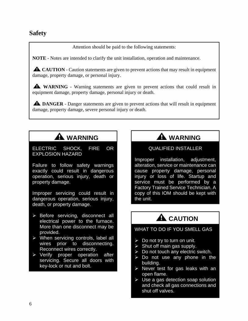
6
Safety
ELECTRIC SHOCK FIRE OR EXPLOSION HAZARD Failure to follow safety warnings exactly could result in dangerous operation serious injury death or property damage Improper servicing could result in dangerous operation serious injury death or property damage Before servicing disconnect all
electrical power to the furnace More than one disconnect may be provided
When servicing controls label all wires prior to disconnecting Reconnect wires correctly
Verify proper operation after servicing Secure all doors with key-lock or nut and bolt
WARNING
Attention should be paid to the following statements
NOTE - Notes are intended to clarify the unit installation operation and maintenance
CAUTION - Caution statements are given to prevent actions that may result in equipment
damage property damage or personal injury
WARNING - Warning statements are given to prevent actions that could result in
equipment damage property damage personal injury or death
DANGER - Danger statements are given to prevent actions that will result in equipment
damage property damage severe personal injury or death
QUALIFIED INSTALLER Improper installation adjustment alteration service or maintenance can cause property damage personal injury or loss of life Startup and service must be performed by a Factory Trained Service Technician A copy of this IOM should be kept with the unit
WARNING
WHAT TO DO IF YOU SMELL GAS Do not try to turn on unit Shut off main gas supply Do not touch any electric switch Do not use any phone in the
building Never test for gas leaks with an
open flame Use a gas detection soap solution
and check all gas connections and shut off valves
CAUTION
7
FIRE EXPLOSION OR CARBON MONOXIDE POISONING HAZARD Failure to replace proper controls could result in fire explosion or carbon monoxide poisoning Failure to follow safety warnings exactly could result in serious injury death or property damage Do not store or use gasoline or other flammable vapors and liquids in the vicinity of this appliance
Electric shock hazard Before servicing shut off all electrical power to the unit including remote disconnects to avoid shock hazard or injury from rotating parts Follow proper Lockout-Tagout procedures
WARNING
VARIABLE FREQUENCY DRIVES
Do not leave VFDs unattended in hand mode or manual bypass Damage to personnel or equipment can occur if left unattended When in hand mode or manual bypass mode VFDs will not respond to controls or alarms
WARNING
WARNING
During installation testing servicing and troubleshooting of the equipment it may be necessary to work with live electrical components Only a qualified licensed electrician or individual properly trained in handling live electrical components shall perform these tasks Standard NFPA-70E an OSHA regulation requiring an Arc Flash Boundary to be field established and marked for identification of where appropriate Personal Protective Equipment (PPE) be worn should be followed
WARNING
GROUNDING REQUIRED All field installed wiring must be completed by qualified personnel Field installed wiring must comply with NECCEC local and state electrical code requirements Failure to follow code requirements could result in serious injury or death Provide proper unit ground in accordance with these code requirements
WARNING
Electric motor over-current protection and overload protection may be a function of the Variable Frequency Drive to which the motors are wired Never defeat the VFD motor overload feature The overload ampere setting must not exceed 115 of the electric motors FLA rating as shown on the motor nameplate
CAUTION
8
PVC (Polyvinyl Chloride) and CPVC (Chlorinated Polyvinyl Chloride) are vulnerable to attack by certain chemicals Polyolester (POE) oils used with R-410A and other refrigerants even in trace amounts in a PVC or CPVC piping system will result in stress cracking of the piping and fittings and complete piping system failure
CAUTION
UNIT HANDLING To prevent injury or death lifting equipment capacity shall exceed unit weight by an adequate safety factor Always test-lift unit not more than 24 inches high to verify proper center of gravity lift point to avoid unit damage injury or death
WARNING
Door compartments containing hazardous voltage or rotating parts are equipped with door latches to allow locks Door latch are shipped with nut and bolts requiring tooled access If you do not replace the shipping hardware with a pad lock always re-install the nut amp bolt after closing the door
CAUTION
Rotation must be checked on all MOTORS AND COMPRESSORS of 3 phase units at startup by a qualified service technician Scroll compressors are directional and can be damaged if rotated in the wrong direction Compressor rotation must be checked using suction and discharge gauges Fan motor rotation should be checked for proper operation Alterations should only be made at the unit power connection
CAUTION
Do not use oxygen acetylene or air in place of refrigerant and dry nitrogen for leak testing A violent explosion may result causing injury or death
WARNING
To prevent damage to the unit do not use acidic chemical coil cleaners Use alkaline chemical coil cleaners with a pH value of 5-9 after mixing without first using an aluminum corrosion inhibitor in the cleaning solution
CAUTION
9
1 Startup and service must be performed by
a Factory Trained Service Technician
2 The unit is for outdoor use only See
General Information section for more
information
3 Every unit has a unique equipment
nameplate with electrical operational
and unit clearance specifications Always
refer to the unit nameplate for specific
ratings unique to the model you have
purchased
4 READ THE ENTIRE INSTALLATION
OPERATION AND MAINTENANCE
MANUAL OTHER IMPORTANT
SAFETY PRECAUTIONS ARE
PROVIDED THROUGHOUT THIS
MANUAL
5 Keep this manual and all literature
safeguarded near or on the unit
Some chemical coil cleaning compounds are caustic or toxic Use these substances only in accordance with the manufacturerrsquos usage instructions Failure to follow instructions may result in equipment damage injury or death
WARNING
Do not clean DX refrigerant coils with hot water or steam The use of hot water or steam on refrigerant coils will cause high pressure inside the coil tubing and damage to the coil
CAUTION
Polyolester (POE) and Polyvinylether (PVE) oils are two types of lubricants used in hydrofluorocarbon (HFC) refrigeration systems Refer to the compressor label for the proper compressor lubricant type
CAUTION
COMPRESSOR CYCLING
3 MINUTE MINIMUM OFF TIME To prevent motor overheating compressors must cycle off for a minimum of 3 minutes
3 MINUTE MINIMUM ON TIME To maintain the proper oil level compressors must cycle on for a minimum of 3 minutes The cycle rate must not exceed 6 starts per hour
WARNING
10
LN Series Feature String Nomenclature
Model Options Unit Feature Options
GE
N
MJ
RE
V
SIZ
E
SE
RIE
S
MN
RE
V
VL
T
A1
A2
A3
A4
A5
B1
B2
B3
B4
1
2
3A
3B
3C
3D
4A
4B
4C
4D
5A
5B
5C
5D
6
7
8A
8B
8C
9
10A
10B
10C
10D
LN A ndash 140 ndash C ndash A ndash 3 ndash F A C 0 E ndash 0 0 0 0 A 0 ndash 0 0 0 0 ndash 0 0 0 0 ndash 0 0 0 0 ndash 0 0 ndash 0 0 0 ndash 0 ndash 0 E 0 0 ndash
0 0 0 0 0 ndash 0 A 0 0 0 ndash 0 0 0 0 0 ndash 0 0 0 0 0 0 ndash 0 0 0 0 0 ndash 0 0 0 B
11
12
13
14
15
16
17
18
19
20
21
22
23
24
25
26A
26B
26C
26D
26E
26F
27
28
29
30
31
32
33
34
35
MODEL OPTIONS SERIES AND GENERATION
LN
MAJOR REVISION
A
UNIT SIZE
045 = 45 ton Capacity
055 = 55 ton Capacity
060 = 60 ton Capacity
075 = 75 ton Capacity
095 = 95 ton Capacity
105 = 105 ton Capacity
120 = 120 ton Capacity
140 = 140 ton Capacity
SERIES
A = 45-60 ton units
B = 75 ton unit
C = 95-140 ton units
MINOR REVISION
A
VOLTAGE
2 = 230V3Φ60Hz
3 = 460V3Φ60Hz
4 = 575V3Φ60Hz
8 = 208V3Φ60Hz
A1 COMPRESSOR STYLE
F = R-410A Tandem VFD Compatible Scroll
Compressor
A2 CONDENSER STYLE
A = Air-Cooled Microchannel Condenser
A3 EVAPORATOR CONFIGURATION
A = Standard Brazed Plate Constant Flow
B = Oversized Brazed Plate Constant Flow
C = Standard Shell amp Tube Constant Flow
D = Oversized Shell amp Tube Constant Flow
A4 COATING
0 = Standard
E = Polymer E-Coated Condenser Coil
A5 STAGING
0 = Staged Compressors
E = All Circuits with Variable Capacity Compressors
- 2 Circuits
G = Half Circuits with Variable Capacity
Compressors - 2 Circuits
B1 BLANK
0 = Standard
B2 BLANK
0 = Standard
B3 BLANK
0 = Standard
B4 BLANK
0 = Standard
UNIT FEATURE OPTIONS 1 UNIT ORIENTATION
A = Standard Access Left Water Connections
B = Standard Access Right Water Connections
C = Standard Access Bottom Water Connections
2 PUMPING STYLE
0 = No Pumps
B = Constant Flow Primary Pumping System - Large
Pipe Size
D = Variable Flow Primary Pumping System - Large
Pipe Size
11
LN Series Feature String Nomenclature
Model Options Unit Feature Options
GE
N
MJR
EV
S
IZE
SE
RIE
S
MN
RE
V
VL
T
A1
A2
A3
A4
A5
B1
B2
B3
B4
1
2 3A
3B
3C
3D
4A
4B
4C
4D
5A
5B
5C
5D
6
7
8A
8B
8C
9
10A
10B
10C
10D
LN A ndash 140 ndash C ndash A ndash 3 ndash F A C 0 E ndash 0 0 0 0 A 0 ndash 0 0 0 0 ndash 0 0 0 0 ndash 0 0 0 0 ndash 0 0 ndash 0 0 0 ndash 0 ndash 0 E 0 0 ndash
0 0 0 0 0 ndash 0 A 0 0 0 ndash 0 0 0 0 0 ndash 0 0 0 0 0 0 ndash 0 0 0 0 0 ndash 0 0 0 B
11
12
13
14
15
16
17
18
19
20
21
22
23
24
25
26A
26B
26C
26D
26E
26F
27
28
29
30
31
32
33
34
35
3A BUILDING PUMP CONFIGURATION
0 = No Building Pumps
A = 1 Pump + High Eff Motor
B = 1 Dual Pump + High Eff Motors
D = 1 Pump + VFD + High Eff Motor
E = 1 Dual Pump + 2 VFDs + High Eff Motors
K = 1 Pump + Field Installed VFD + High Eff Motor
L = 1 Dual Pump + 2 Field Installed VFDs + High
Eff Motors
3B BUILDING PUMP SERIES AND RPM
0 = No Building Pumps
A = 4360 (1170 nominal rpm)
B = 4360 (1760 nominal rpm)
C = 4360 (3520 nominal rpm)
D = 4380 (1170 nominal rpm)
E = 4380 (1760 nominal rpm)
F = 4380 (3520 nominal rpm)
K = 4382 (1170 nominal rpm)
L = 4382 (1760 nominal rpm)
M = 4382 (3520 nominal rpm)
3C PUMP SIZE
0 = No Building Pumps
A = 15B
B = 2B
C = 2D
D = 3D
E = 15x15x6
F = 2x2x6
G = 3x3x6
H = 4x4x6
J = 6x6x6
K = 15x15x8
L = 2x2x8
M = 3x3x8
N = 4x4x8
P= 5x5x8
Q = 6x6x8
R = 8x8x8
S = 2x2x10
T = 3x3x10
U = 4x4x10
V = 6x6x10
W = 8x8x10
Y = 4x4x115
Z = 5x5x115
1 = 6x6x115
2 = 8x8x115
3 = 4x4x13
4 = 6x6x13
5 = 8x8x13
12
LN Series Feature String Nomenclature
GE
N
MJR
EV
S
IZE
SE
RIE
S
MN
RE
V
VL
T
A1
A2
A3
A4
A5
B1
B2
B3
B4
1
2
3A
3B
3C
3D
4
A
4B
4C
4D
5A
5B
5C
5D
6
7
8A
8B
8C
9
1
0A
10
B
10
C
10D
LN A ndash 140 ndash C ndash A ndash 3 ndash F A C 0 E ndash 0 0 0 0 A 0 ndash 0 0 0 0 ndash 0 0 0 0 ndash 0 0 0 0 ndash 0 0 ndash 0 0 0 ndash 0 ndash 0 E 0 0 -
0 0 0 0 0 ndash 0 A 0 0 0 ndash 0 0 0 0 0 ndash 0 0 0 0 0 0 ndash 0 0 0 0 0 ndash 0 0 0 B
11
12
13
14
15
16
17
18
19
20
21
22
23
24
25
26A
26B
26C
26D
26E
26F
27
28
29
30
31
32
33
34
35
3D BUILDING PUMP MOTOR SIZE
0 = No Building Pumps
C = 1 hp
E = 2 hp
F = 3 hp
G = 5 hp
H = 75 hp
J = 10 hp
K = 15 hp
L = 20 hp
M = 25 hp
N = 30 hp
P = 40 hp
Q = 50 hp
4A BLANK
0 = Standard
4B BLANK
0 = Standard
4C BLANK
0 = Standard
4D BLANK
0 = Standard
5A BLANK
0 = Standard
5B BLANK
0 = Standard
5C BLANK
0 = Standard
5D BLANK
0 = Standard
6 REFRIGERATION OPTIONS
0 = Standard
A = Hot Gas Bypass on Non-Variable Capacity
Circuits
B = Hot Gas Bypass - All Circuits
7 REFRIGERATION ACCESSORIES
0 = Standard
A = Sight Glass
B = Compressor Isolation Valves
C = Option A + B
8A UNIT DISCONNECT TYPE
0 = Standard Single Point Power Block
A = Single Point Power Non-fused Disconnect
8B DISCONNECT SIZE
0 = Power Block
N = 100 amps
R = 150 amps
U = 225 amps
V = 250 amps
Z = 400 amps
3 = 600 amps
5 = 800 amps
7 = 1200 amps
8C BLANK
0 = Standard
9 ACCESSORIES
0 = Standard
B = Phase amp Brown Out Protection
10A UNIT CONTROL SEQUENCE
0 = Standard Controls
10B UNIT CONTROL SUPPLIER
E = MCS Controls
10C CONTROL SUPPLIER OPTIONS
0 = Standard
A = Touchscreen Interface
C = Modem
G = Option A + C
Model Options Unit Feature Options
13
LN Series Feature String Nomenclature
Model Options Unit Feature Options
GE
N
MJR
EV
S
IZE
SE
RIE
S
MN
RE
V
VL
T
A1
A2
A3
A4
A5
B1
B2
B3
B4
1
2
3A
3B
3C
3D
4A
4B
4C
4D
5A
5B
5C
5D
6
7
8A
8B
8C
9
10A
10B
10C
10
D
LN A ndash 140 ndash C ndash A ndash 3 ndash F A C 0 E ndash 0 0 0 0 A 0 ndash 0 0 0 0 ndash 0 0 0 0 ndash 0 0 0 0 ndash 0 0 ndash 0 0 0 ndash 0 ndash 0 E 0 0 ndash
0 0 0 0 0 ndash 0 A 0 0 0 ndash 0 0 0 0 0 ndash 0 0 0 0 0 0 ndash 0 0 0 0 0 ndash 0 0 0 B
11
12
13
14
15
16
17
18
19
20
21
22
23
24
25
26
A
26
B
26
C
26D
26E
26F
27
28
29
30
31
32
33
34
35
10D BMS CONNECTION amp DIAGNOSTICS
0 = None
A = BACnet IP
B = BACnet MSTP
C = Modbus IP
D = Modbus RTU
E = Lontalk
H = No BMS Connection with Diagnostics
J = BACnet IP with Diagnostics
K = BACnet MSTP with Diagnostics
L = Modbus IP with Diagnostics
M = Modbus RTU with Diagnostics
N = Lontalk with Diagnostics
11 BLANK
0 = Standard
12 VESTIBULE ACCESSORIES
0 = Standard
C = Vestibule Heating (Electric)
13 MAINTENANCE ACCESSORIES
0 = Standard
A = 115VAC Convenience Outlet Factory Wired
B = 115VAC Convenience Outlet Field Wired
C = Service Lights
F = Options A + C
J = Options B + C
14 BLANK
0 = Standard
15 CODE OPTIONS
0 = Standard ETL USA Listing
A = Chicago Code
B = ETL USA + Canada Listing
16 SHIPPING SPLITS
0 = One Piece Unit
17 AIR-COOLED CHILLER ACCESSORIES
H = Cond Coil Guards + Three Phase Cond Fan
Motor + Fan Cycling- 35degF Low Ambient
J = Cond Coil Guards + VFD Cond Fan Head
Pressure Control - 0degF Low Ambient
18 BLANK
0 = Standard
19 BLANK
0 = Standard
20 BLANK
0 = Standard
21 BLANK
0 = Standard
22 BLANK
0 = Standard
23 BLANK
0 = Standard
24 CHILLER ACCESSORIES 1
0 = Standard
A = Glycol Chiller
C = Thermometers amp Pressure Gauges
G = Option A + C
25 BLANK
0 = Standard
26A BLANK
0 = Standard
26B BLANK
0 = Standard
26C BLANK
0 = Standard
14
LN Series Feature String Nomenclature
Model Options Unit Feature Options
GE
N
MJR
EV
S
IZE
SE
RIE
S
MN
RE
V
VL
T
A1
A2
A3
A4
A5
B1
B2
B3
B4
1
2
3A
3B
3C
3D
4A
4B
4C
4D
5A
5B
5C
5D
6
7
8A
8B
8C
9
10A
10B
10C
10D
LN A ndash 140 ndash C ndash A ndash 3 ndash F A C 0 E ndash 0 0 0 0 A 0 ndash 0 0 0 0 ndash 0 0 0 0 ndash 0 0 0 0 ndash 0 0 ndash 0 0 0 ndash 0 ndash 0 E 0 0 ndash
0 0 0 0 0 ndash 0 A 0 0 0 ndash 0 0 0 0 0 ndash 0 0 0 0 0 0 ndash 0 0 0 0 0 ndash 0 0 0 B
11
12
13
14
15
16
17
18
19
20
21
22
23
24
25
26A
26B
26C
26
D
26
E
26
F
27
28
29
30
31
3
2
33
34
35
26D BLANK
0 = Standard
26E BLANK
0 = Standard
26F BLANK
0 = Standard
27 BLANK
0 = Standard
28 BLANK
0 = Standard
29 BLANK
0 = Standard
30 BLANK
0 = Standard
31 BLANK
0 = Standard
32 BLANK
0 = Standard
33 WARRANTY
0 = Standard Warranty
D = Compressor Warranty Years 2-5
34 CABINET MATERIAL
0 = Standard - Double Wall + R-13 Foam Insulation
35 PAINT amp SPECIAL PRICING
AUTHORIZATIONS
B = Premium AAON Gray Paint Exterior
E = Premium AAON Gray Paint Exterior + Shrink
Wrap
X = Special Pricing Authorization + Premium AAON
Gray Paint Exterior
1 = SPA + Premium AAON Gray Paint Exterior +
Shrink Wrap
4 = Special Pricing Authorization + Special Exterior
Paint Color
7 = SPA + Special Exterior Paint Color + Shrink
Wrap
15
General Information
AAON LN Series chillers are complete self-
contained liquid chilling units They are
assembled wired charged and run-tested
Models are available for air-cooled
applications Chiller primary pumping
packages are available as optional features
Codes and Ordinances
LN Series units have been tested and
certified by ETL in accordance with UL
Safety Standard 1995CSA C222 No 236
System should be sized in accordance with
the American Society of Heating
Refrigeration and Air Conditioning
Engineers Handbook
Installation of LN Series units must conform
to the ICC standards of the International
Mechanical Code the International Building
Code and local building plumbing and
waste water codes All appliances must be
electrically grounded in accordance with
local codes or in the absence of local codes
the current National Electric Code
ANSINFPA 70 or the current Canadian
Electrical Code CSA C221
Receiving Unit
When received the unit should be checked
for damage that might have occurred in
transit If damage is found it should be noted
on the carrierrsquos Freight Bill A request for
inspection by carrierrsquos agent should be made
in writing at once Nameplate should be
checked to ensure the correct model sizes and
voltages have been received to match the job
requirements
If repairs must be made to damaged goods
then the factory should be notified before any
repair action is taken in order to protect the
warranty Certain equipment alteration
repair and manipulation of equipment
without the manufacturerrsquos consent may void
the product warranty Contact AAON
Technical Support for assistance with
Improper installation adjustment alteration service or maintenance can cause property damage personal injury or loss of life Startup and service must be performed by a Factory Trained Service Technician
WARNING
The Clean Air Act of 1990 bans the intentional venting of refrigerant as of July 1 1992 Approved methods of recovery recycling or reclaiming must be followed
CAUTION
Coils and sheet metal surfaces present sharp edges and care must be taken when working with equipment
Failure to observe the following instructions will result in premature failure of your system and possible voiding of the warranty
WARNING
WARNING
16
handling damaged goods repairs and freight
claims (918) 382-6450
Storage
If installation will not occur immediately
following delivery store equipment in a dry
protected area away from construction traffic
and in the proper orientation as marked on the
packaging with all internal packaging in
place Secure all loose-shipped items
Chiller
Failure to observe the following instructions
will result in premature failure of your
system and possible voiding of the warranty
Never turn off the main power supply to the
unit except for complete shutdown When
power is cut off from the unit any
compressors using crankcase heaters cannot
prevent refrigerant migration This means the
compressor will cool down and liquid
refrigerant may accumulate in the
compressor The compressor is designed to
pump refrigerant gas and damage may occur
when power is restored if liquid enters the
compressor
Before unit operation the main power switch
must be turned on for at least 24 hours for
units with compressor crankcase heaters
This will give the crankcase heater time to
clear any liquid accumulation out of the
compressor before it is required to run
Rotation must be checked on all MOTORS AND COMPRESSORS of three phase units All motors to include and not be limited to pump motors and condenser fan motors should all be checked by a qualified service technician at startup and any wiring alteration should only be made at the unit power connection
CAUTION
Scroll compressors are directional and will be damaged by operation in the wrong direction Low pressure switches on compressors have been disconnected after factory testing Rotation should be checked by a qualified service technician at startup using suction and discharge pressure gauges and any wiring alteration should only be made at the unit power connection
CAUTION
CRANKCASE HEATER OPERATION
Units may be equipped with compressor crankcase heaters which should be energized at least 24 hours prior to cooling operation to clear any liquid refrigerant from the compressors
CAUTION
COMPRESSOR CYCLING
3 MINUTE MINIMUM OFF TIME To prevent motor overheating compressors must cycle off for a minimum of 3 minutes
3 MINUTE MINIMUM ON TIME To maintain the proper oil level compressors must cycle on for a minimum of 3 minutes The cycle rate must not exceed 6 starts per hour
WARNING
17
Never cut off the main power supply to the
unit except for complete shutdown Always
control the system from the building
management system or control panel never
at the main power supply (except for
emergency or for complete shutdown of the
system)
Scroll compressors must be on a minimum of
3 minutes and off for a minimum of 3
minutes The cycle rate must be no more than
6 starts per hour
The chiller is furnished with a pressure
differential switch that is factory installed
between the chilled water supply and return
connections This sensor must not be
bypassed since it provides a signal to the unit
controller that water flow is present in the
heat exchanger and the unit can operate
without the danger of freezing the liquid
Compressor life will be seriously shortened
by reduced lubrication and the pumping of
excessive amounts of liquid oil and liquid
refrigerant
Wiring Diagrams
A complete set of unit specific wiring
diagrams in both ladder and point-to-point
form are laminated in plastic and located
inside the control compartment door
General Maintenance
When the initial startup is made and on a
periodic schedule during operation it is
necessary to perform routine service checks
on the performance of the chiller This
includes reading and recording suction
pressures and checking for normal sub-
cooling and superheat See the air-cooled
condenser sections in this manual for specific
details
Chiller Primary Pumping
Primary pumping uses a single pump to move
water (or glycol) through the chiller barrel
and back to the building This pumping
package provides a constant or variable flow
of water to the system The pump is activated
whenever the chiller is given a run signal
Water enters the unit through the return water
piping and then travels through an air
separator to remove any air that is entrapped
in the water Following this the water flows
through a suction guide with strainer The
end of the suction guide is removable for
strainer access The strainer assembly is
composed of two parts the operational
strainer and the startup strainer (located
inside the operational strainer) which is to be
removed 24 hours after startup
The pump is installed after the suction guide
and before a combination valve (Flo-Trex)
This combination valve acts as isolation
valve check valve and flow balancing valve
The shell and tube or brazed plate evaporator
is placed after the combination valve in the
water circuit with a flow switch installed
across its inlet and outlet This flow switch
closes when the velocity is above 07 feet per
second The closing flow switch signals the
control system to indicate flow through the
heat exchanger and allow cooling to activate
as required to maintain the setpoint The
water exiting the chiller evaporator leaves the
unit through the water out connection
18
Automatic Air Vent
There is an automatic air vent installed at the
high point of the system inside the pumping
package compartment The air vent valve
must be in the proper position for operation
Ensure that the small vent cap is loosened two
turns from the closed position allowing air to
be vented from the system It is advisable to
leave the cap on to prevent impurities from
entering the valve See appendix for
additional information
Dual Pumps
When redundant pumping is required factory
installed dual pumps can be ordered A dual
pump is a pump with two independent motors
and pumps in a single casing This dual pump
has a swing split-flapper valve in the
discharge port to prevent liquid recirculation
when only one pump is operating Isolation
valves in the casing allow one pump to be
isolated and removed for service while the
other pump is still operating
The controls package will activate the pump
when the unit is given a run command If the
controls do not recognize flow in 60 seconds
the second pump will be activated and an
alarm signal will be generated If the second
pump does not activate the cooling will be
locked out See appendix for additional
information
Pressure Gauges and Thermometers
Pressure gauges and thermometers are
available as a factory installed option
Thermometers are installed on the inlet and
outlet of the unit One pressure gauge is
installed at each pump This pressure gauge
is connected in three places to the water
piping before the suction guidestrainer after
the suction guide and before the pump and
after the pump There is also a needle valve
at each of these points to isolate the pressure
To measure the pressure at any given point
open the needle valve at that point and close
the other two needle valves One gauge is
used so that the calibration of the pressure
gauge is irrelevant in the calculation of the
differential pressure
Pipe Insulation
The water piping and components on units
with pumping packages are not insulated at
the factory Insulation should be installed on
the water piping after the system has been
checked for leaks
19
Installation
Chiller Placement
The AAON LN Series is designed for
outdoor applications and mounting at ground
level or on a rooftop It must be placed on a
level and solid foundation that has been
prepared to support its weight
The placement relative to the building air
intakes and other structures must be carefully
selected Be sure to observe the dimensions
that are on the rating plate of the chiller for
operational and service clearances
Table 1 - Service Clearances
Location Unit Size
45-140 tons
Front -
(Controls Side) 72rdquo
Back 72rdquo
Ends 96rdquo
Top Unobstructed
Condenser coils and fans must be free of any
obstructions in order to start and operate
properly with a correct amount of airflow
For proper unit operation the immediate area
around condenser must remain free of debris
that may be drawn in and obstruct airflow in
the condensing section
Consideration must be given to obstruction
caused by snow accumulation when placing
the unit
Curb and Steel Mount Installation
Make openings in the roof decking large
enough to allow for water piping electrical
penetrations and workspace only Do not
make openings larger than necessary Set the
curb to coincide with the openings Make
sure curb is level
If the LN is installed on a curb use a curb cap
for the open area under the condenser section
Unit specific curb drawing is included with
job submittal See SMACNA Architectural
Sheet Metal Manual for curb installation
details
Units require rail support along all four sides
of the unit base
When installed at ground level a one-piece
concrete slab should be used with footings
that extend below the frost line Care must
also be taken to protect the coil and fins from
damage due to vandalism or other causes
If unit is elevated a field supplied catwalk is
recommended to allow access to unit service
doors
This unit ships with a curb gasket that is 1frac14rdquo
wide and 1frac12rdquo tall It is recommended that this
or another similar gasket be used between the
curb and the unit to reduce vibration from the
unit to the building
All roofing work should be performed by competent roofing contractors to avoid any possible leakage
CAUTION
Figure 1 - LN Base
20
Figure 2 - Curb Mounting with Dimensions
Figure 3 - Steel Mounting Rail with
Dimensions
Table 2 - Mounting Dimensions
Tons A B C D
45-140 142rdquo 138rdquo 134rdquo 139rdquo
Figure 2
Figure 3
Lifting and Handling
If cables or chains are used to hoist the unit
they must be the same length and care should
be taken to prevent damage to the cabinet
See Figure 5 and Figure 6 for additional
information
Before lifting unit be sure that all shipping
material has been removed from unit Secure
hooks and cables at all lifting points lugs
provided on the unit
Hoist unit to a point directly above the curb
or mounting rail Be sure that the gasket
material has been applied to the curb or
mounting rail
Carefully lower and align unit with utility and
duct openings Lower the unit until the unit
skirt fits around the curb Make sure the unit
is properly seated on the curb and is level
Figure 4 - Lifting Points
21
Figure 5 - Lifting Detail of a 45-60 ton Unit
Figure 6 - Lifting Detail of a 75-140 ton Unit
Lifting slot locations are unit specific
Unit must be rigged at all marked lifting points
22
Water Connection
Connect the supply and return water lines
The connection size is listed on the unit rating
sheet along with the designed volumetric
flow rate The maximum operating pressure
for AAON LN Series units is 125 psi
Mounting Isolation
For roof mounted applications or anytime
vibration transmission is a factor vibration
isolators may be used
Access Doors
Lockable access door is provided to the
compressor and control compartment A
separate access door is also provided to the
pumping package compartment
A light switch with service lights is provided
on the wall of the compressor and control
compartment
End Flashing Installation
On all LN Series units the cabinet width will
overhang the shipping trailer on each side
In order to secure and protect the unit during
transit the sheet metal end flashings have
been removed from the unit The slot created
at the base of each end of the unit allows the
unit to set firmly on the trailer deck
Sheet metal flashings are shipped loose with
the unit and once the unit is set into place the
flashings must be installed on each end of the
unit to complete the finished seal at the base
The flashings are unit specific and designed
to cover the slot at each end of the unit to
prevent water run-off into the curb
Failure to attach and seal the end of unit with
the flashings may result in water leakage into
the curb
Figure 7 - Factory Supplied End Flashings
PVC (Polyvinyl Chloride) and CPVC (Chlorinated Polyvinyl Chloride) are vulnerable to attack by certain chemicals Polyolester (POE) oils used with R-410A and other refrigerants even in trace amounts in a PVC or CPVC piping system will result in stress cracking of the piping and fittings and complete piping system failure
CAUTION
The chiller must be operated only with liquid flowing through the evaporators
WARNING
Installing Contractor is responsible for proper sealing of the water piping entries into the unit Failure to seal the entries may result in damage to the unit and property
CAUTION
23
Low Ambient Operation
If the chiller is ordered for a Low Ambient
application the liquid system must use a
glycol solution and the piping must be
insulated to be prepared for freezing
conditions Care must be taken in the source
of electrical power for the heating tape and
thermostat
Electrical
The single point electrical power connections
are made in the electrical control
compartment
The microprocessor control furnished with
the unit is supplied with its own power supply
factory wired to the main power of the
outdoor mechanical room
Verify the unit nameplate voltage agrees with
the power supply Connect power and control
field wiring as shown on the unit specific
wiring diagram provided with the unit
Size supply conductors based on the unit
MCA rating Supply conductors must be
rated a minimum of 167degF (75degC)
Route power and control wiring separately
through the utility entry Do not run power
and signal wires in the same conduit
Protect the branch circuit in accordance with
code requirements The unit must be
electrically grounded in accordance with
local codes or in the absence of local codes
the current National Electric Code
ANSINFPA 70 or the current Canadian
Electrical Code CSA C221
Power wiring is to the unit terminal block or
main disconnect All wiring beyond this point
has been done by the manufacturer and
cannot be modified without effecting the
units agencysafety certification
Figure 8 - Front View of Utility Entry and
Power Switch from Control Compartment
Electric shock hazard Before attempting to perform any installation service or maintenance shut off all electrical power to the unit at the disconnect switches Unit may have multiple power supplies Failure to disconnect power could result in dangerous operation serious injury death or property damage
WARNING
In order to prevent water leakage into the roof curb the factory provided sheet metal flashings MUST BE attached to the unit base to cover the shipping slots at both ends of the unit
CAUTION
24
Startup technician must check for proper
motor rotation and check fan motor amperage
listed on the motor nameplate is not
exceeded Motor overload protection may be
a function of the variable frequency drive and
must not be bypassed
Note All units are factory wired for
208230V 460V or 575V If unit is to be
connected to a 208V supply the transformer
must be rewired to 208V service For 208V
service interchange the yellow and red
conductor on the low voltage control
transformer
Red-Black for 208V
Yellow-Black for 230V
Wire control signals to the unitrsquos low voltage
terminal block located in the controls
compartment All wiring beyond this point
has been completed by the manufacturer and
cannot be modified without effecting the
unitrsquos agencysafety certification
If any factory installed wiring must be
replaced use a minimum 221degF (105degC) type
AWM insulated conductors
Supply voltage must be within the minmax
range shown on the unit nameplate Available
short circuit current should not exceed the
short circuit current rating (SCCR) shown on
the unit nameplate
Three phase voltage imbalance will cause
motor overheating and premature failure
The maximum allowable imbalance is 5
Voltage imbalance is defined as 100 times the
maximum deviation from the average voltage
divided by the average voltage
Example
(218V+237V+235V)3 = 230V then
100(230V-218V)230V = 52 which
exceeds the allowable imbalance
Check voltage imbalance at the unit
disconnect switch and at the compressor
terminal Contact your local power company
for line voltage corrections
Three phase voltage imbalance will cause motor overheating and premature failure
CAUTION
Scroll compressors are directional and will be damaged by operation in the wrong direction Low pressure switches on compressors have been disconnected after factory testing Rotation should be checked by a qualified service technician at startup using suction and discharge pressure gauges and any wiring alteration should only be made at the unit power connection
Installing Contractor is responsible for proper sealing of the electrical and gas entries into the unit Failure to seal the entries may result in damage to the unit and property
CAUTION CAUTION
25
Variable Speed Compressors
Variable speed compressors should not be
operated outside the factory determined
frequency range The factory determined
compressor VFD frequency range is given
below in Table 3
Table 3- Tandem Circuited Variable Speed
Compressor VFD Frequency Range
Model (LN-) Compressor VFD
Range (Hz)
208V 230V 460V and 575V Units
045 055 060 45-65Hz
075 45-70Hz
095 105 120 35-60 Hz
140 35-65 Hz
No variable speed compressor shall operate below 35 Hz Operating variable speed compressors outside the frequency range specified in this manual voids all warranties and may result in compressor failure
CAUTION
Rotation must be checked on all MOTORS AND COMPRESSORS of three phase units Condenser fan motors should all be checked by a qualified service technician at startup and any wiring alteration should only be made at the unit power connection Variable frequency drives are programmed to automatically rotate the fan in the correct rotation Do not rely on fans with variable frequency drives for compressor rotation
CAUTION
26
Startup (See back of the manual for startup form)
Before the startup of the chiller be sure that
the following items have been checked
1 Verify that electrical power is available to
the unit
2 Verify that any remote stopstart device
connected to the chiller controller is
requesting the chiller to start
3 Verify that liquid flow is present through
the chiller from the building
4 There should be a building load of at least
25 of the chiller capacity in order to
properly check operation
5 With the main power switch off review
the MCS Controller Manual provided
with the chiller Understand the keypad
functions how to set the leaving water
temperature setpoint and how to initiate
the Run State
Use the general check list at the top of the
startup form to make a last check that all the
components are in place water flow is
present and the power supply is energized
Using the controller keypad individually set
the outputs in ldquoManual Onrdquo to confirm relay
closure and compressor operation
Cycle through all the compressors to confirm
that all are operating within tolerance
While performing the check use the startup
form to record observations of compressor
amps and refrigerant pressures
When all is running properly place the
controller in the Run mode and observe the
system until it reaches a steady state of
operation
Note For more information on programming
the controller refer to the MCS Controller
manual provided with the chiller
Electric shock hazard Shut off all electrical power to the unit to avoid shock hazard or injury from rotating parts
WARNING
Improper installation adjustment alteration service or maintenance can cause property damage personal injury or loss of life Startup and service must be performed by a Factory Trained Service Technician
WARNING
Rotation must be checked on all MOTORS AND COMPRESSORS of three phase units All motors to include and not be limited to pump motors and condenser fan motors should all be checked by a qualified service technician at startup and any wiring alteration should only be made at the unit power connection
CAUTION
Before completing installation a complete operating cycle should be observed to verify that all components are functioning properly
CAUTION
27
Axial Flow Condenser Fans
Multi-Wing Z Series Aluminum Fan Blade
Pitch Angle Setting Instructions
1 Maintain the balance of fan
Mark the hub castings across a joint so the
fan hub can be reassembled in the same
orientation
Mark the location of any balancing weight
Balancing weight will be on the outer bolt
circle in the form of washers andor longer
bolts or an additional balancing nut
Number the blades and blade sockets so that
they are replaced into their original position
Figure 9 - Fan with the HUB on the top and
RET on the bottom
2 Determine the direction of rotation
Right R is clockwise when facing the
discharge side of the fan and Left L is
counterclockwise when facing the discharge
side of the fan
3 Determine the bushing mount location
The bushing mount is the center section of the
hub through which the fan is mounted to the
shaft and typically contains either setscrews
or a center-tapered hole where the bushing
inserts
Location A is with the bushing mount on air
inlet side of the fan
Location B is with the bushing mount on air
discharge side of the fan
Figure 10 - Bushing Mount Location
4 Determine the pin location groove
Disassemble fan on a flat surface and note in
which groove the pin is located
Figure 11 - RET with Pin in Groove 4
Bushing
Mount
A B Bushing
Mount
Bushing Bushing
1 2 3 4
28
5 Determine whether the pin is in the HUB
or RET
Figure 12 - Fan HUB and RET Castings
6 Determine the current blade pitch and the pin location for the new blades
Table 4 - ReturnExhaust Fan Pin Location
Type Bushing
Mount
Blade Pitch Angle
20deg 25deg 28deg 30deg 33deg 35deg 38deg 40deg 45deg 50deg
5Z A - RET - RET RET RET HUB HUB HUB HUB
B - HUB - HUB HUB HUB RET RET RET RET
Table 5 - ReturnExhaust Fan Pin Location
Type Rot Blade Pitch Angle
20deg 25deg 28deg 30deg 33deg 35deg 38deg 40deg 45deg 50deg
5Z R - 4 - 3 2 1 4 3 2 1
L - 1 - 2 3 4 1 2 3 4
7 Replace fan blades in the new pin
location and reassemble the fan
Replace the blades with the pin in the 1 2 3
or 4 groove position of either the HUB or
RET Assemble the fan making sure to place
the blades in their previous blade sockets to
match up the previous orientation of HUB
and RET and to replace any balancing
weights in their previous locations Tighten
bolts in a cross pattern to 5-6 ft-lbs of torque
29
Multi-Wing W Series Black Glass
Reinforced Polypropylene Fan Blade Pitch
Angle Setting Instructions
Contact the AAON parts department to
acquire the new pitch pins for the fan blades
Note original position of retaining plates
center boss and all hardware including
additional hardware used for balancing
1 Remove all the bolts and nuts
2 Determine blade rotation ndash on the concave
side of the blade is a blade marking showing
6WR 6WL 7WL 7WR or 9WR The ldquoLrdquo
and ldquoRrdquo denote the rotation of the blade
3 Replace the pitch insert in the blade root
with an insert of the desired pitch
Figure 13 - Pitch Insert
4 Replace blades to their original location
5 Replace all nuts bolts and washers on the
fan hub
6 Replace retaining plates and center boss to
original location
7 Tighten nuts and bolts to 14 ft-lbs of
torque
Fan Assembly Bushings
The fan assembly bushings should be
tightened to the specifications listed in the
following table
Table 6 - Fan Assembly Bushing Torque
Specifications
Bushing Tightening Torque
(in-lbs)
H X 1125 95
H X 1375 95
SH X 1125 108
SH X 1375 108
SD X 1125 108
SD X 1375 108
SD X 1625 108
SD X 1875 108
SK X 2125 180
30
Maintenance
General
Qualified technicians must perform routine
service checks and maintenance This
includes reading and recording the
condensing and suction pressures and
checking for normal sub-cooling and
superheat
Air-cooled chillers require maintenance
schedulesprocedures Unit specific
instructions are included in this manual
Compressors
The scroll compressors are fully hermetic and
require no maintenance except keeping the
shell clean
Refrigerant Suction Line Filter
Each refrigerant circuit contains a
replaceable core suction line filter One
month after start-up remove the filter
element
The replaceable core suction filters are
provided with pressure taps and shutoff
valves for isolation when removing the filter
For safety purposes a service manifold must
be attached prior to filter maintenance
Suction Filter Removal Instructions
1 Shut down operation of the unit
2 Close both shut-off valves to isolate
the suction filter
3 Reclaim the refrigerant from the
suction filter section
4 Remove the bolts from the suction
filter end plate
5 Remove the pleated filter assembly
Prior to filter core service a service manifold MUST BE attached to in and out pressure connections to assure no pressure exists during filter maintenance Non-compliance could result in injury or violation of EPA regulations
Service gauges MUST BE connected before operating the isolation valves for the replaceable core filter
WARNING
WARNING
31
6 Replace the suction filter end plate
and bolts
7 Evacuate the suction filter assembly
to 500 microns
8 Open both shut-off valves
Adjusting Refrigerant Charge
All AAON chillers are shipped with a full
factory charge Periodically adjusting the
charge of a system may be required
Adjusting the charge of a system in the field
must be based on determination of liquid sub-
cooling and evaporator superheat On a
system with an expansion valve liquid sub-
cooling is more representative of the charge
than evaporator superheat but both
measurements must be taken
Before Charging
Refer to the unit nameplate as a reference
when determining the proper refrigerant
charge
Unit being charged must be at or near full
load conditions before adjusting the charge
Units equipped with hot gas bypass must
have the hot gas bypass valve closed to get
the proper charge
After adding or removing charge the system
must be allowed to stabilize typically 10-15
minutes before making any other
adjustments
The type of unit and options determine the
ranges for liquid sub-cooling and evaporator
superheat Refer to Table 7 when determining
the proper sub-cooling
For units equipped with low ambient (0degF)
option see the special charging instructions at
the end of this section
Checking Liquid Sub-cooling
Measure the temperature of the liquid line as
it leaves the condenser coil
Read the gauge pressure at the liquid line
close to the point where the temperature was
taken You must use liquid line pressure as it
will vary from discharge pressure due to
condenser coil pressure drop
Convert the pressure obtained to a saturated
temperature using the appropriate refrigerant
temperature-pressure chart
Subtract the measured liquid line temperature
from the saturated temperature to determine
the liquid sub-cooling
Compare calculated sub-cooling to the table
below for the appropriate unit type and
options
The Clean Air Act of 1990 bans the intentional venting of refrigerant (CFCrsquos and HCFCrsquos) as of July 1 1992 Approved methods of recovery recycling or reclaiming must be followed Fines andor incarceration may be levied for non-compliance
CAUTION
Polyolester (POE) and Polyvinylether (PVE) oils are two types of lubricants used in hydrofluorocarbon (HFC) refrigeration systems Refer to the compressor label for the proper compressor lubricant type
CAUTION
32
Checking Evaporator Superheat
Measure the temperature of the suction line
close to the compressor
Read gauge pressure at the suction line close
to the compressor
Convert the pressure obtained to a saturated
temperature using the appropriate refrigerant
temperature-pressure chart
Subtract the saturated temperature from the
measured suction line temperature to
determine the evaporator superheat
For refrigeration systems with tandem scroll
compressors it is critical that the suction
superheat setpoint on the expansion valve is
set with one compressor running The suction
superheat should be 10-13degF with one
compressor running The suction superheat
will increase with both compressors in a
tandem running Inadequate suction
superheat can allow liquid refrigerant to
return to the compressors which will wash the
oil out of the compressor Lack of oil
lubrication will destroy a compressor Liquid
sub-cooling should be measured with both
compressors in a refrigeration system
running
Compare calculated superheat to Table 7 for
the appropriate unit type and options
Table 7 - Acceptable Refrigeration Circuit
Values
Air-Cooled Chiller with Scroll
Compressors
Sub-Cooling2 12-18degF
Superheat1 10-15degF 1 One compressor running in tandem 2 Two compressors running in tandem
Adjusting Sub-cooling and Superheat
Temperatures
The system is overcharged if the sub-cooling
temperature is too high and the evaporator is
fully loaded (low loads on the evaporator
result in increased sub-cooling) and the
evaporator superheat is within the
temperature range as shown in Table 7 (high
superheat results in increased sub-cooling)
Correct an overcharged system by reducing
the amount of refrigerant in the system to
lower the sub-cooling
The system is undercharged if the superheat
is too high and the sub-cooling is too low
Correct an undercharged system by adding
refrigerant to the system to reduce superheat
and raise sub-cooling
If the sub-cooling is correct and the superheat
is too high the expansion valve may need
adjustment to correct the superheat
Expansion valves must be adjusted to approximately 10-15degF of suction superheat Failure to have sufficient superheat will damage the compressor and void the warranty
CAUTION
DO NOT OVERCHARGE Refrigerant overcharging leads to excess refrigerant in the condenser coils resulting in elevated compressor discharge pressure
CAUTION
33
Table 8 - R-410A Refrigerant Temperature-Pressure Chart
F psig F psig F psig F psig F psig
20 783 50 1422 80 2349 110 3641 140 5401
21 800 51 1448 81 2386 111 3691 141 5470
22 818 52 1474 82 2423 112 3742 142 5539
23 836 53 1501 83 2460 113 3794 143 5609
24 854 54 1528 84 2498 114 3846 144 5679
25 872 55 1555 85 2537 115 3899 145 5751
26 891 56 1582 86 2575 116 3952 146 5823
27 910 57 1610 87 2614 117 4005 147 5896
28 929 58 1638 88 2654 118 4059 148 5969
29 949 59 1667 89 2694 119 4114 149 6044
30 968 60 1696 90 2735 120 4169 150 6119
31 988 61 1725 91 2776 121 4225
32 1009 62 1754 92 2817 122 4282
33 1029 63 1784 93 2859 123 4339
34 1050 64 1815 94 2901 124 4396
35 1071 65 1845 95 2944 125 4454
36 1092 66 1876 96 2987 126 4513
37 1114 67 1907 97 3030 127 4573
38 1136 68 1939 98 3075 128 4632
39 1158 69 1971 99 3119 129 4693
40 1181 70 2004 100 3164 130 4754
41 1203 71 2036 101 3210 131 4816
42 1227 72 2070 102 3256 132 4878
43 1250 73 2103 103 3302 133 4941
44 1274 74 2137 104 3349 134 5005
45 1298 75 2171 105 3396 135 5069
46 1322 76 2206 106 3444 136 5134
47 1347 77 2241 107 3493 137 5200
48 1372 78 2277 108 3542 138 5266
49 1397 79 2313 109 3591 139 5333
34
Lubrication
All original motors and bearings are
furnished with an original factory charge of
lubrication Certain applications require
bearings be re-lubricated periodically The
schedule will vary depending on operating
duty temperature variations or severe
atmospheric conditions
Bearings should be re-lubricated at normal
operating temperatures but not when
running
Rotate the fan shaft by hand and add only
enough grease to purge the seals DO NOT
OVERLUBRICATE
Air-Cooled Condenser
The air-cooled condenser section rejects heat
by passing outdoor air over the fin tube coils
for cooling of the hot refrigerant gas from the
compressors The heated air will discharge
from the top of the section through the axial
flow fans
The condenser coils should be inspected
yearly to ensure unrestricted airflow If the
installation has a large amount of airborne
dust or other material the condenser coils
should be cleaned according to the
microchannel coil cleaning section
Brazed Plate Heat Exchanger Cleaning
Because of a normally high degree of
turbulence in brazed plate heat exchangers
for many applications the heat exchanger
channels are self-cleaning For applications
that are not self-cleaning (ie hard water at
high temperatures etc) or applications where
additional cleaning is desired it is possible to
clean the brazed plate heat exchanger by
circulating a cleaning liquid
Use a tank with weak acid 5 phosphoric
acid (H3PO4) or if the exchanger is
frequently cleaned 5 oxalic acid (H2C2O4)
Pump the cleaning liquid through the
exchanger For optimum cleaning the
cleaning solution flow rate should be a
minimum of 15 times the normal flow rate
preferably in a back-flush mode After
cleaning the heat exchanger must be rinsed
with clean water A solution of 1-2 sodium
hydroxide (NaOH) or sodium bicarbonate
(NaHCO) before the last rinse ensures that all
acid is neutralized
E-Coated Coil Cleaning
Documented quarterly cleaning of e-coated
coils is required to maintain coating warranty
coverage
Surface loaded fibers or dirt should be
removed prior to water rinse to prevent
restriction of airflow If unable to back wash
the side of the coil opposite of the coils
entering air side then surface loaded fibers or
dirt should be removed with a vacuum
cleaner If a vacuum cleaner is not available
a soft non-metallic bristle brush may be used
In either case the tool should be applied in
the direction of the fins Coil surfaces can be
easily damaged (fin edges bent over) if the
tool is applied across the fins
Use of a water stream such as a garden hose
against a surface loaded coil will drive the
fibers dirt and salts into the coil This will
make cleaning efforts more difficult Surface
loaded fibers must be completely removed
prior to using low velocity clean water rinse
Electric shock hazard Shut off all electrical power to the unit to avoid shock hazard or injury from rotating parts
WARNING
35
Quarterly cleaning is required to maintain
warranty coverage and is essential to
maintain the life of an E-coated coil Coil
cleaning shall be part of the units regularly
scheduled maintenance procedures
Failure to clean an E-coated coil on the
prescribed quarterly cycle will void the
warranty and may result in reduced
efficiency and durability in the environment
A routine two-step quarterly coil cleaning is
required to maintain warranty
Step one is to clean the coil with the below
approved coil cleaner (see approved products
list under the Recommended Coil Cleanersrdquo
section
Step two is to use the approved saltchloride
remover under the Recommended Chloride
Removerrdquo section to dissolve soluble salts
and revitalize the unit It is very important
when cleaning andor rinsing not to exceed
130degF and potable water pressure is less than
100 psig to avoid damaging the unit and coil
fin edges
For routine quarterly cleaning first clean the
coil with the below approved coil
cleaner After cleaning the coils with the
approved cleaning agent use the approved
chloride remover to remove soluble salts and
revitalize the unit
Recommended Coil Cleaner ndash Step 1
GulfCoatTM Coil Cleaner assuming it is
used in accordance with the manufacturers
directions on the container for proper mixing
and cleaning has been approved for use on
E-coated coils to remove mold mildew dust
soot greasy residue lint and other
particulate Never use any cleaners that are
not approved
Recommended Chloride Remover ndash Step 2
CHLORRIDreg Concentrate assuming it
is used in accordance with the manufacturers
directions on the container for proper mixing
has been approved for use on E-coated coils
to remove chloridessalts amp sulfates Never
use any chloride removers that are not
approved
Warranty Protection ndash Step 1
Complete the coil cleaning following these
steps
1 Ensure that the power to the unit is off
and locked out
2 Clean the area around the unit if
needed to ensure leaves grass or
High velocity water from a pressure washer or compressed air should only be used at a very low pressure to prevent fin andor coil damages The force of the water or air jet may bend the fin edges and increase airside pressure drop Reduced unit performance or nuisance unit shutdowns may occur
Harsh chemicals household bleach or acid cleaners should not be used to clean e-coated coils These cleaners can be very difficult to rinse out of the coil and can accelerate corrosion and attack the e-coating If there is dirt below the surface of the coil use the recommended coil cleaners
CAUTION
CAUTION
36
loose debris will not be blown into the
coil
3 Remove panels or tops as required
gaining access to the coil(s) to be
cleaned
4 Using a pump up sprayer fill to the
appropriate level with potable water
and add the correct amount of
approved cleaner as per manufacture
instructions leaving room for the
pump plunger to be reinserted
NOTE Coils should always be cleaned
back flushed opposite of airflow to prevent
impacting the dirt into the coil
5 If the coils have heavy dirt fibers
grass leaves etc on the interior or
exterior face areas a vacuum and
brush should be used to remove those
surface contaminants prior to
applying cleaner The interior floor
drain tray or pan areas should also be
vacuumed
6 Apply the mixed cleaner to coil
surfaces using a pressurized pump up
sprayer maintaining a good rate of
pressure and at a medium size nozzle
spray (not a solid stream and not a
wide fan but somewhere in the
middle) Work in sectionspanels
ensuring that all areas are covered and
kept wetted
7 Apply the cleaner to unit interior air
exiting side coil surfaces first Work
in sectionspanels moving side to side
and from top to bottom
8 Generously soak coils by spraying
cleaner directly on and into the fin
pack section to be cleaned and allow
the cleaning solution to soak for 5 to
10 minutes
9 Using pressurized potable water
(lt100 psi) rinse the coils and
continue to always work in
sectionspanels Start at the top of the
coil and slowly move vertically
downward to the bottom Then
staying in the same vertical area
slowly move back up to the top where
you started Now move over slightly
overlapping the area just completed
and repeat above Continue until all
coil areas on the inside of the unit
have been rinsed
10 Complete steps 5-9 for the exterior air
entering side of the coils
11 Final rinse ndash Now complete a quick
rinse of both sides of the coil
including the headers piping u-
bends and hairpins
12 If the coil has a drain pan or unit floor
that is holding rinse water or cleaner
extra time and attention will need to
be taken in those areas to ensure a
proper rinse has been completed
Warranty Protection ndash Step 2
Complete the coil chloride (salt) removal
following these steps
1 CHLORRIDreg is a concentrate to be
used for both normal inland
applications at a 1001 mix ratio OR
for severe coastal applications 501
mix ratio with potable water (256
ounces of Chlorrid to 1 gal of water)
Using a pump up sprayer fill to the
appropriate level with potable water
and add the correct amount of
CHLORRIDreg salt remover leaving
room for the pump plunger to be
reinserted
2 Apply CHLORRIDreg to all external
coil surfaces using a pressurized
pump up sprayer maintaining a good
rate of pressure and at a medium size
nozzle spray (not a solid stream and
not a wide fan but somewhere in the
middle) Work in sectionspanels
ensuring that all areas are covered and
kept wetted
37
3 Generously soak coils by spraying
CHLORRIDreg directly on and into
the fin pack section Let stand for 5 to
10 minutes keeping the area wetted
Do not allow to dry before rinsing
4 Using pressurized potable water
(lt100 psi) rinse the CHLORRIDreg
and dissolved chloridessalts off of
the coils continuing to always work in
sectionspanels
5 Starting at the top of the coil begin
rinsing the coil from side to side until
you reach the bottom Repeat as many
times as is necessary to ensure all coil
sectionspanels have been completed
and are thoroughly rinsed
6 Reinstall all panels and tops that were
removed
Microchannel Coil Cleaning
Documented routine cleaning of
microchannel coils with factory provided e-
coating is required to maintain coating
warranty coverage See E-Coated Coil
Cleaning section
Air-cooled heat exchangers may include
microchannel coils
Cleaning microchannel coils is necessary in
all locations In some locations it may be
necessary to clean the coils more or less often
than recommended In general a condenser
coil should be cleaned at a minimum of once
a year In locations where there is commonly
debris or a condition that causes dirtgrease
build up it may be necessary to clean the coils
more often Proper procedure should be
followed at every cleaning interval Using
improper cleaning technique or incorrect
chemicals will result in coil damage system
performance fall off and potentially leaks
requiring coil replacement
Documented routine cleaning of
microchannel coils with factory provided e-
coating is required to maintain coating
warranty coverage Use the E-Coated Coil
Cleaning section for details on cleaning e-
coated coils
Field applied coil coatings are not
recommended with microchannel coils
Allowed Chemical Cleaners and Procedures
AAON recommends certain chemicals that
can be used to remove buildup of grime and
debris on the surface of microchannel coils
These chemicals have been tested for
performance and safety and are the only
chemicals that AAON will warrant as correct
for cleaning microchannel coils
There are three procedures that are outlined
below that will clean the coils effectively
without damage to the coils Use of any other
procedure or chemical may void the warranty
to the unit where the coil is installed With
all procedures make sure the unit is off
before starting
The water pressure used to clean should not
exceed 140 psi from no closer than 6 inches
from the coils and with the water aimed
perpendicular to the coils
Electric shock hazard Shut off all electrical power to the unit to avoid shock hazard or injury from rotating parts
WARNING
WARNING
38
1 Simple Green
Simple Green is available from AAON Parts
and Supply (Part T10701) and is
biodegradable with a neutral 65 pH
Recommendation is to use it at a 4 to 1 mix
Use the following procedure
1 Rinse the coil completely with water Use
a hard spray but be careful not to bend or
damage the fins A spray that is too hard
will bend the fins Spray from the fan side
of the coil
2 With a pump sprayer filled with a mix of
4 parts water to one part Simple Green
spray the air inlet face of the coil Be sure
to cover all areas of the face of the coil
3 Allow the coil to soak for 10-15 minutes
4 Rinse the coil with water as in step one
5 Repeat as necessary
2 Vinegar
This is standard white vinegar available in
gallons from most grocery stores It has a pH
of 2-3 so it is slightly acidic Use the
following procedure
1 Rinse the coil completely with water Use
a hard spray but be careful not to bend or
damage the fins A spray that is too hard
will bend the fins Spray from the fan side
of the coil
2 Use a pump sprayer filled with vinegar
(100) Spray from the face of the coil in
the same direction as the airflow Be sure
to cover all areas of the face of the coil
3 Allow the coil to soak for 10-15 minutes
4 Rinse the coil with water as in step one
5 Repeat as necessary
3 Water Flush
This procedure can be used when the only
material to cause the coil to need cleaning is
debris from plant material that has impinged
the coil face
1 Rinse the coil completely with water Use
a hard spray but be careful not to bend or
damage the fins A spray that is too hard
will bend the fins Spray from the fan side
of the coil
2 Spray and rinse the coil from the face
Application Examples
The three procedures can be used to clean
microchannel coils They will fit with the
application depending on the area In some
areas where the springsummer has a large
cottonwood bloom 3 might work fine if the
unit is installed on an office building and no
other environmental factors apply
When a unit is installed where the sprinkler
system has water being sprayed onto the
condenser coil you might have better results
using 2 Vinegar is slightly acidic and may
help with the calcium build up from drying
water This also works well when grease is
part of the inlet air to a condenser coil
Generally the best and broadest based
procedure is 1 The grease cutting effect of
the Simple Green is good for restaurant
applications
Other Coil Cleaners
There are many cleaners on the market for
condenser coils Before using any cleaner
that is not covered in this section you must
get written approval from the AAON
warranty and service department Use of
unapproved chemicals will void the
warranty
Use pressurized clean water with pressure not to exceed 140 psi Nozzle should be 6rdquo and 80deg to 90deg from coil face Failure to do so could result in coil damage
CAUTION
39
AAON testing has determined that unless a
chemical has a neutral pH (6-8) it should not
be used
Beware of any product that claims to be a
foaming cleaner The foam that is generated
is caused by a chemical reaction to the
aluminum fin material on tube and fin coils
and with the fin tube and coating material on
microchannel coils
Microchannel coils are robust in many ways
but like any component they must be treated
correctly This includes cleaning the coils
correctly to give optimal performance over
many years
Service
If the unit will not operate correctly and a
service company is required only a company
with service technicians qualified and
experienced in both refrigerant chillers and
air conditioning are permitted to service the
systems to keep warranties in effect If
assistance is required the service technician
must contact AAON
Replacement Parts
Parts for AAON equipment may be obtained
from your local AAON representative When
ordering parts reference the unit serial
number and part number
AAON Technical Support
2424 S Yukon Ave
Tulsa OK 74107
Ph (918) 382-6450
techsupportAAONcom
wwwAAONcom
Note Before calling technician should have
model and serial number of the unit available
for the service department to help answer
questions regarding the unit
40
Appendix - Water Piping Component Information
Automatic Air Vent Valves
Automatic Air Vent Valves provide
automatic air venting for hot or cold water
distribution systems These vents purge air
that may be in the water system
The vent valve utilizes a float to actuate the
valve plug which is located at the top of the
valve Once the air is displaced and the
system pressure is sustained the valve plug
seals and prevents any water from escaping
from the system
The float vent can also operate as an anti-
vacuum device since it will permit air to enter
the system when it must be drained It can
also be installed to permit the separation and
dispersal of air while fluid is actually
circulating in the system
Overview
Body and cover are brass construction
Air vent with silicone rubber seal
Impurities do not usually affect function
as maximum float line of water is always
lower than the valve seal
Float is high temperature resistant
polyethylene
Suitable for use with glycol systems
Can be disassembled for inspection and
cleaning
Operating Range
Minimum working pressure 145psi
(10 kPa)
Maximum working pressure 150psi
(10 bars)
Temperature Range 33degF ndash 240degF
(5degC ndash 116degC)
Performance
Performance curve details the quantity of air
vented by the ldquoFloat Ventrdquo according to the
pressure in the system
Note In order to get the best results in
venting air from risers use connecting pipes
41
of at least 1frasl2 diameter between the ldquoFloat
Ventrdquo valves and installation
Installation
When the air vent valve is installed as shown
the air will not be vented while the fluid is
circulating in the system but it can vent when
the system is shut off
The figure below shows the installation of the
vent valve for the venting of air while the
fluid is circulating in the system and the
required increase in pipe size in order to
obtain proper separation of air from water
The valve should be mounted only in a
vertical position as its operation is based on
the vertical movement of the float
While the air vent valve is in operation back
off the small vent cap two turns This is the
proper operating setting which will allow air
to be vented from the system It is advisable
to leave the cap on to prevent impurities from
entering the valve
Maintenance
No maintenance is normally necessary
However if the FV-4M1 is disassembled for
inspection or cleaning it is important that
when re-assembling to ensure that the spring
loaded lever properly engages under the float
collar
42
Dimensions ndash Weights
Pumps - Installation and Operating
Instructions
Introduction
This document contains specific information
regarding the safe installation operating and
maintenance of Vertical In-Line pumps and
should be read and understood by installing
operating and maintenance personnel The
equipment supplied has been designed and
constructed to be safe and without risk to
health and safety when properly installed
operated and maintained The instructions
following must be strictly adhered to If
clarification is needed on any point please
contact Armstrong quoting the equipment
serial number
Where under normal operating conditions the
limit of 68degC155degF (Restricted Zone) for
normal touch or 80degC176degF (Unrestricted
Zone) for unintentional touch may be
experienced steps should be taken to
minimize contact or warn operatorsusers that
normal operating conditions will be
exceeded In certain cases where the
temperature of the pumped liquid exceeds the
above stated temperature levels pump casing
temperatures may exceed 100degC212degF and
not withstanding pump insulation techniques
appropriate measures must be taken to
minimize risk for operating personnel
Storage
Pumps removed from service and stored
must be properly prepared to prevent
excessive rusting Pump port protection
plates must not be removed until the pump is
ready to connect to the piping Rotate the
shaft periodically (At least monthly) to keep
No Installation of this equipment should take place unless this document has been read and understood
CAUTION
43
rotating element free and bearings fully
functional
For long term storage the pump must be
placed in a vertical position in a dry
environment Internal rusting can be
prevented by removing the plugs at the top
and bottom of the casing and drain or air blow
out all water to prevent rust buildup or the
possibility of freezing Be sure to reinstall the
plugs when the unit is made operational
Rust-proofing or packing the casing with
moisture absorbing material and covering the
flanges is acceptable When returning to
service be sure to remove the drying agent
from the pump
Handling Large VIL Units
One effective way of lifting a large pumping
unit is to place lifting hooks through the
motor lifting rings or straps around the upper
part of the motor The pump and motor unit
will free-stand on the casing ribs Remove the
coupling guard and place (2) lifting straps
through the pumpmotor pedestal one on
each side of the motor shaft and secure to the
lifting device
With the straps in place using a spacer bar if
necessary to protect the motor fan cover the
whole assembly can now be lifted securely
Note Handling transportation and
installation of this equipment should only be
undertaken by trained personnel with proper
use of lifting equipment
Remove coupling guard and place lifting
straps on each side of coupling use spacer
bar if necessary to protect motor fan cover
Vertical Inline Pump Lifting Strap
Positioning
Note All split-coupled pumps contain a
tapped hole in the motor bracket above the
discharge flange for draining the well Pipe
this drain hole to a floor drain to avoid
overflow of the cavity caused by collecting
chilled water condensate or from seal failure
Pump Piping - General
The discharge valve only is to be used to
throttle pump flow not the suction valve
Care must be taken in the suction line layout
and installation as it is usually the major
source of concern in centrifugal pump
applications
Discharge valve only is to be used to throttle pump flow
Use Caution Piping may carry high temperature fluid
CAUTION
CAUTION
44
Alignment
Alignment is unnecessary on close-coupled
pumps as there is no shaft coupling
Split-coupled units are accurately aligned at
the factory prior to being shipped and do not
need re-aligning when installed
Pump Operation
Starting Pump
Ensure that the pump turns freely by hand or
with some mechanical help such as a strap
and lever on larger pumps Ensure that all
protective guarding is securely fixed in
position
The pump must be fully primed on start up
Fill the pump casing with liquid and rotate the
shaft by hand to remove any air trapped in the
impeller On split coupled units any air
trapped in the casing as the system is filled
must be removed by the manual air vent in
the seal flush line Close-coupled units are
fitted with seal flushvent lines piped to the
pump suction area When these units operate
residual air is drawn out of the pump towards
the suction piping
lsquoBumprsquo or energize the motor momentarily
and check that the rotation corresponds with
the directional arrow on the pump casing To
reverse rotation of a three phase motor
interchange any two power leads
Start the pump with the discharge valve
closed and the suction valve open and then
gradually open the discharge valve when the
motor is at operating speed The discharge
valve may be lsquocrackedrsquo or open slightly at
start up to help eliminate trapped air
When stopping the pump Close the
discharge valve and de-energize the motor
DO NOT run the pump against a closed
discharge valve for an extended period of
time (A few minutes maximum)
Star-Delta motor starters should be fitted
with electronicmechanical interlocks that
have a timed period of no more than 40
milliseconds before switching from star
(Starting) to delta (Run) connection yet allow
the motor to reach full star (Starting) speed
before switching to delta (Run)
Should the pump be noisy or vibrate on start-
up a common reason is overstated system
head Check this by calculating the pump
operating head by deducting the suction
pressure gauge value from the discharge
gauge reading Convert the result into the
units of the pump head as stated on the pump
nameplate and compare the values Should
the actual pump operating head be
significantly less than the nameplate head
value it is typically permissible to throttle the
discharge isolation valve until the actual
operating head is equal to the nameplate
value
Any noise or vibration usually disappears
The system designer or operator should be
made aware of this soon as some adjustment
may be required to the pump impeller
diameter or drive settings if applicable to
make the pump suitable for the system as
installed
Do not run pumps with discharge valve closed or under very low flow conditions
CAUTION
Check rotation arrow prior to operating the unit
CAUTION
45
Check rotation arrow prior to operating the
unit The rotation of all Vertical In-Line units
is ldquoclockwiserdquo when viewed from the drive
end (Looking from on top of behind the
motor)
General Care
Vertical In-Line pumps are built to operate
without periodic maintenance other than
motor lubrication on larger units A
systematic inspection made at regular
intervals will ensure years of trouble-free
operation giving special attention to the
following
Keep unit clean
Keep moisture refuse dust or other loose
particles away from the pump and
ventilating openings of the motor
Avoid operating the unit in overheated
surroundings (Above 100ordmF40ordmC)
Any possibility of the unit starting while
being serviced must be eliminated
If mechanical seal environmental accessories
are installed ensure water is flowing through
the sight flow indicator and that filter
cartridges are replaced as recommended
Pump Lubrication
Lubrication is not required There are no
bearings in the pump that need external
lubrication service
Large Series split-coupled units are installed
with a shaft bushing located beneath the
impeller that is lubricated from the pump
discharge This bearing is field removable for
service on the 20x20x19 size without
disturbing the motor or other major pump
components
Motor
Follow the lubrication procedures
recommended by the motor manufacturer
Many small and medium sized motors are
permanently lubricated and need no added
lubrication Generally if there are grease
fittings evident the motor needs periodic
lubrication and if there are no grease fittings
evident no periodic lubrication is required
Check the lubrication instructions supplied
with the motor for the particular frame size
indicated on the motor nameplate
Mechanical Seal
Mechanical seals require no special attention
The mechanical seal is fitted with a flush line
The seal is flushed from discharge of the
pump casing on split-coupled pumps and is
flushedvented to the suction on close
coupled pumps
The split-coupled pump is flushed from the
pump discharge because the mechanical seal
chamber is isolated from the liquid in the
pump by a throttle bushing Because the seal
chamber is isolated seal environmental
controls such as filters and separators when
installed in the split-coupled flush line are
very effective as only the seal chamber needs
cleansing and will prolong seal life in HVAC
systems
Do not run the pump unless properly filled
with water as the mechanical seals need a
film of liquid between the faces for proper
operation
Electric shock hazard Before attempting to perform any service or maintenance on pumping unit disconnect power source to the driver LOCK IT OFF and tag with the reason
WARNING
46
Mechanical seals may lsquoweeprsquo slightly at
start-up Allow the pump to continue
operating for several hours and the
mechanical seal to lsquoseatrsquo properly prior to
calling for service personnel
System Cleanliness
Before starting the pump the system must be
thoroughly cleaned flushed and drained and
replenished with clean liquid
Welding slag and other foreign materials
ldquoStop Leakrdquo and cleaning compounds and
improper or excessive water treatment are all
detrimental to the pump internals and sealing
arrangement
Proper operation cannot be guaranteed if the
above conditions are not adhered to
Note
Particular care must be taken to check the
following before the pump is put into
operation
1 Pump primed
2 Rotation OK
3 Lubrication OK
4 Pipe work properly supported
5 Voltage supply OK
6 Overload protection OK
7 Is the system clean
8 Is the area around the pump clean
Warranty
Does not cover any damages to the
equipment resulting from failure to observe
the above precautions
Noise Levels
Estimated Pumping Unit Sound Power Level Decibels A-Weighted at 1 m (3 ft) from unit
Double Check Prior to Startup
CAUTION
47
Vibration Levels
Vertical In-Line pumps are designed to meet vibration levels set by Hydraulic Institute Standard
HI Pump Vibration 964 Standard levels are as detailed below
Dual Pump Specific Information
Dual Pump Flapper Valve Operating
Instructions
This unit is fitted with internal valves to allow
isolation of one pump for service and to
automatically prevent recirculation of the
flow when only one pump is running
Procedure for Parallel or Stand-By
Pumping
Discharge and suction valve stems should be
locked in the center position This is
indicated by both locking handles in the
vertical position and the center pin of the
locking arms (4) locked by the handles This
procedure allows the discharge flapper valves
to pivot freely and locks the suction valve
firmly in the center position
Procedure for Isolation of One Side
1 Stop the pump to be serviced
2 Close and lock the suction and discharge
valves as per instructions below
3 Ensure seal flush line interconnection
valve is closed and drain the isolated
casing
4 Service isolated pump as required
Procedure for Starting the Pump after
Servicing
1 Ensure serviced pump is fully re-
assembled including all seal flush lines
and drain plugs
2 Fill the dry casing with system fluid by
opening the seal flush line
interconnecting valve and the air vent
fitting
3 Allow the pressure to equalize in the two
casings if necessary by opening seal
flush line interconnected valve
4 Unlock the discharge valve as per
instructions below
5 Unlock the suction valve as per
instructions below
NOTE Keep hands and tools away from
locked suction valve arm as the differential
pressure may cause the arm to rotate quickly
with force when unlocked
6 Close the seal flush line interconnect
valve and restart pump
Valve Operation - Refer to following 3rdquo 4rdquo
amp 6rdquo valve illustration and the 8rdquo valve
illustration
48
Discharge Valve
This valve performs the dual function of
automatically sealing the discharge of the
inactive pump when one pump is running and
can manually be closed and locked to isolate
one pump for service
Automatic Flapper Operation
In the flapper mode the two halves of the
discharge valve are free to pivot
independently under normal operating
conditions The locking handle (3) should be
secured with the set screw (11) in the vertical
position with the center pin of the locking
arm (4) trapped by the locking handle (3)
Manual Valve Locking
The locking feature of this valve is to ensure
a positive seal (leak proof) of the discharge
port on the pump to be serviced
Note Ensure the pump to be isolated is not
operating before attempting to release the
locking mechanism Failure to do so may
result in injury to the operator andor damage
to the pump
Locking
1 Loosen discharge side set screw (11) to
release the locking handle (3)
2 Rotate the discharge side locking handle
(3) so that the handle points toward the
pump to be serviced and secure in the
horizontal position using set screw (11)
This releases the discharge locking arm
(4)
3 Rotate discharge valve shaft (16) towards
the pump to be isolated The orientation
of the shaft is indicated by the center pin
on the locking arm (4)
4 Raise the locking handle (3) so that the
cam on the base of the handle forces the
pin of the locking arm (4) towards the
pump to be isolated The locking handle
(3) should be raised to between 45
degrees and the vertical position
5 Tighten set screw (11) to lock the locking
handle (3) in position
This handle should not be rotated past the
vertical position
Note Ensure the isolated pump is not
operating before attempting to release the
locking mechanism Failure to do so may
result in injury to the operator andor damage
the pump
Unlocking
1 Open the interconnecting valve on the
seal flush line to pressurize the serviced
pump and vent air through bleeder valve
on series 4302
2 Close these valves once the pressure is
equalized and air removed
3 Loosen set screw (11) and lower locking
handle (3) to the horizontal position
secure with set screw (11)
4 Rotate valve to center position so that the
center pin of the locking arm (4) locates
in the recess on the locking handle (3)
5 Loosen set screw (11) and raise locking
arm (3) to the vertical position locking
the center pin in the locking arm recess
secure with set screw (11)
Suction Valve
Manual Operation
The suction side valve is designed for use as
a manually operated isolation valve This
valve is not designed to automatically pivot
as the discharge flappers do
Locking
1 Loosen suction side set screw (11) to
release the locking handle (3)
Care should be taken when performing procedures 3 and 4 Read instructions carefully
WARNING
49
2 Rotate the suction side locking handle (3)
so that the handle points towards the
pump to be serviced and secure in the
horizontal position using set screw (11)
This releases the suction locking arm (4)
Note The locking handle (3) should only be
rotated towards the pump stopped for service
The suction valve is designed to prevent the
locking handle (1) from rotating towards the
running pump as the suction of the running
pump could cause the valve to slam shut with
sufficient force to injure the operator andor
cause damage to the pump Do not attempt to
circumvent this safety feature
3 Rotate the suction valve towards the
pump to be isolated The orientation of
the shaft is indicated by the center pin on
the locking arm (4)
4 Loosen set screw (11) and raise the
locking handle (3) so that the cam on the
base on the handle forces the pin of the
locking arm (4) towards the pump to be
isolated The locking handle (3) should be
raised to between 45 degrees and the
vertical position
This handle should not be rotated past the
vertical position
5 Tighten set screw (11) to secure the
locking handle (3) in position
Unlocking
1 Open the interconnecting valve on the
seal flush line to pressurize the serviced
pump and vent air through bleeder valve
on series 4302 Close these valves once
the pressure is equalized and air removed
2 Loosen set screw (11) and lower locking
handle (3) to the horizontal position
secure with set screw (11)
NOTE Keep hands and tools away from
suction valve locking arm when freed by
locking handle as differential pressure may
cause arm to rotate quickly with force when
unlocked
3 Rotate valve to center position so that the
center pin of the locking arm (4) is
located in the recess on the locking
handle (3)
4 Loosen set screw (11) and raise locking
arm (3) to the vertical position locking
the center pin in the locking arm recess
secure with set screw
Care should be taken when performing procedures 3 and 4 Read instructions carefully
WARNING
50
51
52
Suction Guides
Introduction
Suction Guides are designed for bolting
directly onto the suction flange of horizontal
or vertical shaft centrifugal pumps
Operating Limits
The suction guide is designed to be a four-
function fitting Each Suction Guide is a 90ordm
elbow a Pipe Strainer and a Flow Stabilizer
It may also be used as a Reducing Elbow
should the suction piping be larger than the
pump inlet
Installation
The Suction Guides may be installed in any
arrangement feasible the arrangement of the
pump flange bolt-holes
Inspection
Suction Guides are thoroughly tested and
inspected before shipment to assure they
meet with your order requirements All units
must be carefully examined upon arrival for
possible damage during transit Any evidence
of mishandling should be reported
immediately to the carrier and noted on the
freight bill
Operation
No special attention need be paid to the
Suction Guide at start-up The fitting is
stationary and will strain the pumped fluid
and stabilize the flow into the pump
automatically
Temporary strainer must be removed
following system clean up
After all debris has been removed from the
system or a maximum of 24 running hours
stop the pump and close the pump isolation
valves Drain the Suction Guide by removing
the drain plug or opening the blowdown
valve if installed
Remove the Suction Guide cover and remove
the strainer assembly from the valve body
A temporary fine-mesh start-up strainer is
tack-welded to the permanent stainless steel
strainer This temporary strainer should now
be removed from the permanent strainer The
fine-mesh strainer is designed to remove
small particulate from new piping systems
and could easily clog with debris if left in
53
place This will be detrimental to the
operation of the pump
Inspect the cover O-ring and replace if
necessary
Replace the permanent strainer into the
fitting body once the temporary strainer is
removed
Replace the cover into the body Ensuring
that the strainer is properly seated tighten the
cover bolts diagonally evenly and firmly
Flo-Trex Combination Valve
Introduction
The Flo-Trex combination valves are
designed for installation on the discharge side
of centrifugal pumps and incorporate three
functions in one valve
1 Drip-tight shut-off valve
2 Spring closure design Non-slam check
valve
3 Flow throttling valve
Armgrip Flange Adapter Installation
1 Position the two halves of the Armgrip
flange adapter on the valve body ensuring
that the lugs on each half of the flange
adapters are located between the anti-
rotation lugs on the valve body (as
shown)
Insert two bolts of specified size (Table A1)
to secure the halves of the flange adapter to
the valve body (as shown)
Table A1 Armgrip Flange Adapter Details
Valve Size
125 psi150 psi 250 psi300 psi
Ductile Iron Bolt Ductile Iron Bolt
No Size No Size
2-12 4 58 8 34
3 4 58 8 34
4 8 58 8 34
5 8 34 8 34
6 8 34 12 34
8 8 34 12 78
10 12 78 16 1
12 12 78 16 1-18
The gasket cavity should face out to the
adjoining flange
2 Lubricate the inner and outer diameter of
the gasket with the lubricant provided or
a similar non-petroleum based water
soluble grease
3 Press the gasket firmly into the flange
cavity ensuring that the sealing lip is
pointed outward When in place the
gasket should not extend beyond the end
of the pipe (as shown)
54
4 Position the adjoining flange or the pipe
to the Armgrip flange adapter and install
the remaining bolts The two locking
bolts should be tightened first in order to
position the flange correctly
Note Care should be taken to ensure that
the gasket is not pinched or bent between
flanges
5 Tighten remaining nuts evenly by
following bolting instructions so that the
flange faces remain parallel (as shown in
the figure labeled Recommended Bolt
Tightening Procedure) Flange bolts
should be tightened to 70 ft-lbs torque
minimum to assure firm metal to metal
contact When raised face flanges are
used there will be a gap between the
faces of the outer diameter
6 Flange gaskets are not interchangeable
with other mechanical pipe couplings or
flange gaskets
Recommended Bolt Tightening Procedure
Field Conversion (Straight to Angle
Pattern Valve
1 Open valve at least one complete turn
2 Remove the body bolts from valve body
using Allen Key
3 Rotate one half of the valve body 180deg
making sure the lower valve seat and O
ring stay in position Inspect the O ring
for any cuts or nicks and replace if
necessary
4 Replace body bolts and torque evenly to
70 ft-lbs
55
Flow Measurement with the valve in the
Wide Open position
Where approximate indication of flow is
acceptable the Flo-Trex valve can be used
Step 1 Measure and record the differential
pressure across the valve
Step 2 With valve in fully open position
locate the pressure differential on left hand
side of the Flo-Trex Performance Curve with
Valve in Full Open Position chart and extend
line horizontally across to valve size being
used Drop line vertically down and read flow
rate from bottom of chart
Safety glasses should be worn Probes should not be left inserted into fittings for long periods of time as leakage may result
CAUTION
56
Flow Measurement with the valve in the
throttled position
Step 1 The valve stem with its grooved rings
and positioning sleeve indicates the throttled
position of the valve
The quarter turn graduations on the sleeve
with the scribed line on the stem provide an
approximate flow measurement
Note The valve is shipped in closed
position The indicator on the plastic sleeve
is aligned with the vertical scribed line on
the stem
Step 2 Record the size of the valve and stem
position using the flow indicator scale
Calculate the percentage of valve opening
based on the number of rings at the fully open
position
Valve Size 2-12 3 4 5 6 8 10 12
Number of
Rings 5 5 6 9 10 12 18 28
(valve
fully open)
Step 3 Measure and record the differential
pressure across the valve in the throttled
position
Step 4 Locate percentage of valve opening
on the bottom scale of Inherent Flow
Characteristic Curve with Valve in Throttled
Position Project line vertically up to intersect
with the Valve Characteristic Curve and from
this point project line horizontally across to
the left of the chart and record the percentage
of maximum flow rate
Step 5 On the Flo-Trex Performance Curve
with Valve in Full Open Position locate the
differential pressure obtained in Step 3 and
project line horizontally across to intercept
with Valve Performance Curve Drop a line
vertically down to read the flow rate at the
bottom of the chart
Step 6 Calculate the flow rate of the valve in
the throttled position by multiplying the flow
rate (Step 5) by the percentage of maximum
flow rate (Step 4)
Example
Valve size 4 in
Differential pressure is 54 ft
Number of open rings is 3
From the table the number of rings for the
4in valve fully open is 6
Divide open rings by total 36 = 50
throttled
57
Example Continued
From the Flo-Trex performance curve a 4in
valve with 54 ft of pressure drop represents
a flow of 400 USgpm
From the flow characteristic curve a 4in
valve at 50 open represents 34 of
maximum flow
The approximate flow of a 4in valve with a
54 ft pressure drop when 50 throttled is
100
34) x (400 =136 USgpm
100
34) x (252 =857 Ls
Note To prevent premature valve failure
it is not recommended that the valve
operate in the throttled position with more
than 25 ft pressure differential Instead the
pump impeller should be trimmed or
valves located elsewhere in the system to
partially throttle the flow
Operation
To assure tight shut-off the valve must be
closed using a wrench with 25 to 30 ft-lbs of
torque
To assure trouble free check valve operation
and shut-off operation the valve should be
periodically opened and closed to keep valve
seat and valve disc guide stem free of buildup
of system contaminants
Repacking of Flo-Trex valve under full
system pressure
If it is necessary the stem O ring can be
changed under full system pressure
Step 1 Record the valve setting
Step 2 Turn the valve stem counterclockwise
until the valve is fully open and will not turn
any further Torque to a maximum of
45 ft-lbs This will ensure good metal to
metal contact and minimal leakage
Step 3 The valve bonnet may now be
removed There may be a slight leakage as
the metal to metal backseating does not
provide a drip-tight seal
Step 4 Clean exposed portion of valve stem
being careful not to leave scratches
Step 5 Remove and replace the O ring
gasket
Step 6 Install the valve bonnet
Step 7 Tightening the valve bonnet is
necessary to stop any leaks
Step 8 Open valve to balance set point as
recorded in Step 1
Note On valve sizes of 2-12 inch and 3
inch the full open position is 5 turns
though the valve will open to 5-12 turns
which is just back of seating of valve
Seat Replacement
Step 1 Drain the system and remove valve
from piping
Step 2 Remove the body bolts from the body
using an Allen Key
Step 3 Remove seat and O Ring O rings are
not used on valves of 8 inches or larger
Step 4 Inspect and clean O ring cavity and
install new O ring and seat Valve disc stem
should be inspected and replaced if worn
Valve stem O ring should be replaced at this
time as discussed under Repacking of Flo-
Trex section
Safety glasses should be worn
CAUTION
58
Pressure-Temperature Limits
Flo-Trex Cross Section
LN Series Startup Form
Job Name_____________________________________________
Date____________
Address____________________________________________________________________
____________________________________________________________________________
Model Number_______________________________________________________________
Serial Number___________________________________________ Tag___________
Startup Contractor____________________________________________________________
Address____________________________________________________________________
_____________________________________________________
Phone____________
Pre Startup Checklist
Installing contractor should verify the following items
1 Is there any visible shipping damage Yes No
2 Is the unit level Yes No
3 Are the unit clearances adequate for service and operation Yes No
4 Do all access doors open freely and are the handles operational Yes No
5 Have all shipping braces been removed Yes No
6 Have all electrical connections been tested for tightness Yes No
7 Does the electrical service correspond to the unit nameplate Yes No
8 On 208230V units has transformer tap been checked Yes No
9 Has overcurrent protection been installed to match the unit nameplate
requirement Yes No
10 Have all set screws on the fans been tightened Yes No
11 Do all fans rotate freely Yes No
12 Does the field water piping to the unit appear to be correct per design
parameters Yes No
Ambient Temperature
Ambient Dry Bulb Temperature ________degF
Ambient Wet Bulb Temperature ________degF
WaterGlycol System
1 Has the entire system been flushed and pressure checked Yes No
2 Have isolation valves to the chiller been installed Yes No
3 Has the entire system been filled with fluid Yes No
4 Has air been bled from the heat exchangers and piping Yes No
5 Is there a minimum load of 50 of the design load Yes No
6 Has the water piping been insulated Yes No
7 Is the glycol the proper type and concentration (NA if water) Yes No
8 What is the freeze point of the glycol (NA if water)
______________________________
Chiller Configuration
Air-Cooled Chiller
Low Ambient Control Condenser Safety Check
No Water Leaks
Water Flow ________ gpm
Chilled Water In Temperature ________degF
Chilled Water Out Temperature ________degF
CompressorsDX Cooling
Check Rotation
Number Model L1 L2 L3
Head
Pressure
PSIG
Suction
Pressure
PSIG
Crankcase
Heater
Amps
1
2
3
4
Refrigeration System 1 - Cooling Mode
Pressure Saturated
Temperature
Line
Temperature Sub-cooling Superheat
Discharge NA NA
Suction NA
Liquid NA
Refrigeration System 2 - Cooling Mode
Pressure Saturated
Temperature
Line
Temperature Sub-cooling Superheat
Discharge NA NA
Suction NA
Liquid NA
Condenser Fans
Alignment
Check Rotation
Nameplate Amps________
Number hp L1 L2 L3
1
2
3
4
5
6
7
8
Pumping Package
hp L1 L2 L3 Flow (gpm)
Chiller Building Pump 1
Chiller Building Pump 2
Maintenance Log
This log must be kept with the unit It is the responsibility of the owner andor maintenanceservice
contractor to document any service repair or adjustments AAON Service and Warranty
Departments are available to advise and provide phone help for proper operation and replacement
parts The responsibility for proper start-up maintenance and servicing of the equipment falls to
the owner and qualified licensed technician
Entry
Date
Action Taken NameTel
Literature Change History
February 2014
Initial version
July 2014
Corrected tonnages for the figures of the lifting details
January 2015
Updated cover picture and Feature 17-H minimum operation temperature
July 2015
Updated Microchannel Coil Cleaning section Updated Flo-Trex images Added Features and
Options Information
August 2016
Changed coil cleaning pressure to 100 psig
October 2017
Added picture to show the open base Added phase imbalance discussion Added frequency
ranges for VFD compressors Changed the minimum compressor cycling times to 3 minutes
Added suction line filter removal instructions
May 2018
Updated technical support contact information
June 2018
Updated E-coated coil cleaning procedure Updated Flo-Trex Combination Valve section
Minor Revision changed to ldquoArdquo because LN is now AHRI certified
AAON
2425 South Yukon Ave
Tulsa OK 74107-2728
wwwAAONcom
LN Series
Installation Operation amp
Maintenance
V28980 Rev A 180627
Factory Technical Support 918-382-6450 Note Before calling Technical Support please have the model and serial number
of the unit available
Parts For replacement parts please contact your local AAON Representative
It is the intent of AAON to provide accurate and current product information However in the
interest of product improvement AAON reserves the right to change pricing specifications
andor design of its product without notice obligation or liability
Copyright copy AAON all rights reserved throughout the world
AAONreg and AAONAIREreg are registered trademarks of AAON Inc Tulsa OK
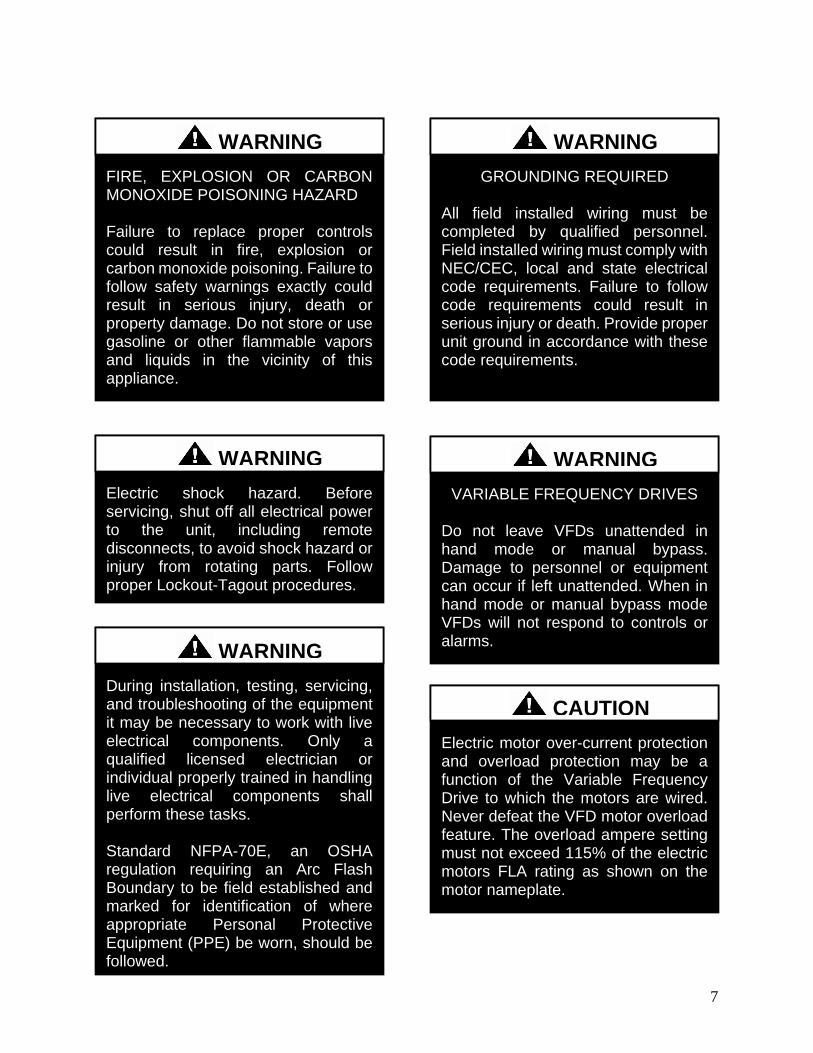
7
FIRE EXPLOSION OR CARBON MONOXIDE POISONING HAZARD Failure to replace proper controls could result in fire explosion or carbon monoxide poisoning Failure to follow safety warnings exactly could result in serious injury death or property damage Do not store or use gasoline or other flammable vapors and liquids in the vicinity of this appliance
Electric shock hazard Before servicing shut off all electrical power to the unit including remote disconnects to avoid shock hazard or injury from rotating parts Follow proper Lockout-Tagout procedures
WARNING
VARIABLE FREQUENCY DRIVES
Do not leave VFDs unattended in hand mode or manual bypass Damage to personnel or equipment can occur if left unattended When in hand mode or manual bypass mode VFDs will not respond to controls or alarms
WARNING
WARNING
During installation testing servicing and troubleshooting of the equipment it may be necessary to work with live electrical components Only a qualified licensed electrician or individual properly trained in handling live electrical components shall perform these tasks Standard NFPA-70E an OSHA regulation requiring an Arc Flash Boundary to be field established and marked for identification of where appropriate Personal Protective Equipment (PPE) be worn should be followed
WARNING
GROUNDING REQUIRED All field installed wiring must be completed by qualified personnel Field installed wiring must comply with NECCEC local and state electrical code requirements Failure to follow code requirements could result in serious injury or death Provide proper unit ground in accordance with these code requirements
WARNING
Electric motor over-current protection and overload protection may be a function of the Variable Frequency Drive to which the motors are wired Never defeat the VFD motor overload feature The overload ampere setting must not exceed 115 of the electric motors FLA rating as shown on the motor nameplate
CAUTION
8
PVC (Polyvinyl Chloride) and CPVC (Chlorinated Polyvinyl Chloride) are vulnerable to attack by certain chemicals Polyolester (POE) oils used with R-410A and other refrigerants even in trace amounts in a PVC or CPVC piping system will result in stress cracking of the piping and fittings and complete piping system failure
CAUTION
UNIT HANDLING To prevent injury or death lifting equipment capacity shall exceed unit weight by an adequate safety factor Always test-lift unit not more than 24 inches high to verify proper center of gravity lift point to avoid unit damage injury or death
WARNING
Door compartments containing hazardous voltage or rotating parts are equipped with door latches to allow locks Door latch are shipped with nut and bolts requiring tooled access If you do not replace the shipping hardware with a pad lock always re-install the nut amp bolt after closing the door
CAUTION
Rotation must be checked on all MOTORS AND COMPRESSORS of 3 phase units at startup by a qualified service technician Scroll compressors are directional and can be damaged if rotated in the wrong direction Compressor rotation must be checked using suction and discharge gauges Fan motor rotation should be checked for proper operation Alterations should only be made at the unit power connection
CAUTION
Do not use oxygen acetylene or air in place of refrigerant and dry nitrogen for leak testing A violent explosion may result causing injury or death
WARNING
To prevent damage to the unit do not use acidic chemical coil cleaners Use alkaline chemical coil cleaners with a pH value of 5-9 after mixing without first using an aluminum corrosion inhibitor in the cleaning solution
CAUTION
9
1 Startup and service must be performed by
a Factory Trained Service Technician
2 The unit is for outdoor use only See
General Information section for more
information
3 Every unit has a unique equipment
nameplate with electrical operational
and unit clearance specifications Always
refer to the unit nameplate for specific
ratings unique to the model you have
purchased
4 READ THE ENTIRE INSTALLATION
OPERATION AND MAINTENANCE
MANUAL OTHER IMPORTANT
SAFETY PRECAUTIONS ARE
PROVIDED THROUGHOUT THIS
MANUAL
5 Keep this manual and all literature
safeguarded near or on the unit
Some chemical coil cleaning compounds are caustic or toxic Use these substances only in accordance with the manufacturerrsquos usage instructions Failure to follow instructions may result in equipment damage injury or death
WARNING
Do not clean DX refrigerant coils with hot water or steam The use of hot water or steam on refrigerant coils will cause high pressure inside the coil tubing and damage to the coil
CAUTION
Polyolester (POE) and Polyvinylether (PVE) oils are two types of lubricants used in hydrofluorocarbon (HFC) refrigeration systems Refer to the compressor label for the proper compressor lubricant type
CAUTION
COMPRESSOR CYCLING
3 MINUTE MINIMUM OFF TIME To prevent motor overheating compressors must cycle off for a minimum of 3 minutes
3 MINUTE MINIMUM ON TIME To maintain the proper oil level compressors must cycle on for a minimum of 3 minutes The cycle rate must not exceed 6 starts per hour
WARNING
10
LN Series Feature String Nomenclature
Model Options Unit Feature Options
GE
N
MJ
RE
V
SIZ
E
SE
RIE
S
MN
RE
V
VL
T
A1
A2
A3
A4
A5
B1
B2
B3
B4
1
2
3A
3B
3C
3D
4A
4B
4C
4D
5A
5B
5C
5D
6
7
8A
8B
8C
9
10A
10B
10C
10D
LN A ndash 140 ndash C ndash A ndash 3 ndash F A C 0 E ndash 0 0 0 0 A 0 ndash 0 0 0 0 ndash 0 0 0 0 ndash 0 0 0 0 ndash 0 0 ndash 0 0 0 ndash 0 ndash 0 E 0 0 ndash
0 0 0 0 0 ndash 0 A 0 0 0 ndash 0 0 0 0 0 ndash 0 0 0 0 0 0 ndash 0 0 0 0 0 ndash 0 0 0 B
11
12
13
14
15
16
17
18
19
20
21
22
23
24
25
26A
26B
26C
26D
26E
26F
27
28
29
30
31
32
33
34
35
MODEL OPTIONS SERIES AND GENERATION
LN
MAJOR REVISION
A
UNIT SIZE
045 = 45 ton Capacity
055 = 55 ton Capacity
060 = 60 ton Capacity
075 = 75 ton Capacity
095 = 95 ton Capacity
105 = 105 ton Capacity
120 = 120 ton Capacity
140 = 140 ton Capacity
SERIES
A = 45-60 ton units
B = 75 ton unit
C = 95-140 ton units
MINOR REVISION
A
VOLTAGE
2 = 230V3Φ60Hz
3 = 460V3Φ60Hz
4 = 575V3Φ60Hz
8 = 208V3Φ60Hz
A1 COMPRESSOR STYLE
F = R-410A Tandem VFD Compatible Scroll
Compressor
A2 CONDENSER STYLE
A = Air-Cooled Microchannel Condenser
A3 EVAPORATOR CONFIGURATION
A = Standard Brazed Plate Constant Flow
B = Oversized Brazed Plate Constant Flow
C = Standard Shell amp Tube Constant Flow
D = Oversized Shell amp Tube Constant Flow
A4 COATING
0 = Standard
E = Polymer E-Coated Condenser Coil
A5 STAGING
0 = Staged Compressors
E = All Circuits with Variable Capacity Compressors
- 2 Circuits
G = Half Circuits with Variable Capacity
Compressors - 2 Circuits
B1 BLANK
0 = Standard
B2 BLANK
0 = Standard
B3 BLANK
0 = Standard
B4 BLANK
0 = Standard
UNIT FEATURE OPTIONS 1 UNIT ORIENTATION
A = Standard Access Left Water Connections
B = Standard Access Right Water Connections
C = Standard Access Bottom Water Connections
2 PUMPING STYLE
0 = No Pumps
B = Constant Flow Primary Pumping System - Large
Pipe Size
D = Variable Flow Primary Pumping System - Large
Pipe Size
11
LN Series Feature String Nomenclature
Model Options Unit Feature Options
GE
N
MJR
EV
S
IZE
SE
RIE
S
MN
RE
V
VL
T
A1
A2
A3
A4
A5
B1
B2
B3
B4
1
2 3A
3B
3C
3D
4A
4B
4C
4D
5A
5B
5C
5D
6
7
8A
8B
8C
9
10A
10B
10C
10D
LN A ndash 140 ndash C ndash A ndash 3 ndash F A C 0 E ndash 0 0 0 0 A 0 ndash 0 0 0 0 ndash 0 0 0 0 ndash 0 0 0 0 ndash 0 0 ndash 0 0 0 ndash 0 ndash 0 E 0 0 ndash
0 0 0 0 0 ndash 0 A 0 0 0 ndash 0 0 0 0 0 ndash 0 0 0 0 0 0 ndash 0 0 0 0 0 ndash 0 0 0 B
11
12
13
14
15
16
17
18
19
20
21
22
23
24
25
26A
26B
26C
26D
26E
26F
27
28
29
30
31
32
33
34
35
3A BUILDING PUMP CONFIGURATION
0 = No Building Pumps
A = 1 Pump + High Eff Motor
B = 1 Dual Pump + High Eff Motors
D = 1 Pump + VFD + High Eff Motor
E = 1 Dual Pump + 2 VFDs + High Eff Motors
K = 1 Pump + Field Installed VFD + High Eff Motor
L = 1 Dual Pump + 2 Field Installed VFDs + High
Eff Motors
3B BUILDING PUMP SERIES AND RPM
0 = No Building Pumps
A = 4360 (1170 nominal rpm)
B = 4360 (1760 nominal rpm)
C = 4360 (3520 nominal rpm)
D = 4380 (1170 nominal rpm)
E = 4380 (1760 nominal rpm)
F = 4380 (3520 nominal rpm)
K = 4382 (1170 nominal rpm)
L = 4382 (1760 nominal rpm)
M = 4382 (3520 nominal rpm)
3C PUMP SIZE
0 = No Building Pumps
A = 15B
B = 2B
C = 2D
D = 3D
E = 15x15x6
F = 2x2x6
G = 3x3x6
H = 4x4x6
J = 6x6x6
K = 15x15x8
L = 2x2x8
M = 3x3x8
N = 4x4x8
P= 5x5x8
Q = 6x6x8
R = 8x8x8
S = 2x2x10
T = 3x3x10
U = 4x4x10
V = 6x6x10
W = 8x8x10
Y = 4x4x115
Z = 5x5x115
1 = 6x6x115
2 = 8x8x115
3 = 4x4x13
4 = 6x6x13
5 = 8x8x13
12
LN Series Feature String Nomenclature
GE
N
MJR
EV
S
IZE
SE
RIE
S
MN
RE
V
VL
T
A1
A2
A3
A4
A5
B1
B2
B3
B4
1
2
3A
3B
3C
3D
4
A
4B
4C
4D
5A
5B
5C
5D
6
7
8A
8B
8C
9
1
0A
10
B
10
C
10D
LN A ndash 140 ndash C ndash A ndash 3 ndash F A C 0 E ndash 0 0 0 0 A 0 ndash 0 0 0 0 ndash 0 0 0 0 ndash 0 0 0 0 ndash 0 0 ndash 0 0 0 ndash 0 ndash 0 E 0 0 -
0 0 0 0 0 ndash 0 A 0 0 0 ndash 0 0 0 0 0 ndash 0 0 0 0 0 0 ndash 0 0 0 0 0 ndash 0 0 0 B
11
12
13
14
15
16
17
18
19
20
21
22
23
24
25
26A
26B
26C
26D
26E
26F
27
28
29
30
31
32
33
34
35
3D BUILDING PUMP MOTOR SIZE
0 = No Building Pumps
C = 1 hp
E = 2 hp
F = 3 hp
G = 5 hp
H = 75 hp
J = 10 hp
K = 15 hp
L = 20 hp
M = 25 hp
N = 30 hp
P = 40 hp
Q = 50 hp
4A BLANK
0 = Standard
4B BLANK
0 = Standard
4C BLANK
0 = Standard
4D BLANK
0 = Standard
5A BLANK
0 = Standard
5B BLANK
0 = Standard
5C BLANK
0 = Standard
5D BLANK
0 = Standard
6 REFRIGERATION OPTIONS
0 = Standard
A = Hot Gas Bypass on Non-Variable Capacity
Circuits
B = Hot Gas Bypass - All Circuits
7 REFRIGERATION ACCESSORIES
0 = Standard
A = Sight Glass
B = Compressor Isolation Valves
C = Option A + B
8A UNIT DISCONNECT TYPE
0 = Standard Single Point Power Block
A = Single Point Power Non-fused Disconnect
8B DISCONNECT SIZE
0 = Power Block
N = 100 amps
R = 150 amps
U = 225 amps
V = 250 amps
Z = 400 amps
3 = 600 amps
5 = 800 amps
7 = 1200 amps
8C BLANK
0 = Standard
9 ACCESSORIES
0 = Standard
B = Phase amp Brown Out Protection
10A UNIT CONTROL SEQUENCE
0 = Standard Controls
10B UNIT CONTROL SUPPLIER
E = MCS Controls
10C CONTROL SUPPLIER OPTIONS
0 = Standard
A = Touchscreen Interface
C = Modem
G = Option A + C
Model Options Unit Feature Options
13
LN Series Feature String Nomenclature
Model Options Unit Feature Options
GE
N
MJR
EV
S
IZE
SE
RIE
S
MN
RE
V
VL
T
A1
A2
A3
A4
A5
B1
B2
B3
B4
1
2
3A
3B
3C
3D
4A
4B
4C
4D
5A
5B
5C
5D
6
7
8A
8B
8C
9
10A
10B
10C
10
D
LN A ndash 140 ndash C ndash A ndash 3 ndash F A C 0 E ndash 0 0 0 0 A 0 ndash 0 0 0 0 ndash 0 0 0 0 ndash 0 0 0 0 ndash 0 0 ndash 0 0 0 ndash 0 ndash 0 E 0 0 ndash
0 0 0 0 0 ndash 0 A 0 0 0 ndash 0 0 0 0 0 ndash 0 0 0 0 0 0 ndash 0 0 0 0 0 ndash 0 0 0 B
11
12
13
14
15
16
17
18
19
20
21
22
23
24
25
26
A
26
B
26
C
26D
26E
26F
27
28
29
30
31
32
33
34
35
10D BMS CONNECTION amp DIAGNOSTICS
0 = None
A = BACnet IP
B = BACnet MSTP
C = Modbus IP
D = Modbus RTU
E = Lontalk
H = No BMS Connection with Diagnostics
J = BACnet IP with Diagnostics
K = BACnet MSTP with Diagnostics
L = Modbus IP with Diagnostics
M = Modbus RTU with Diagnostics
N = Lontalk with Diagnostics
11 BLANK
0 = Standard
12 VESTIBULE ACCESSORIES
0 = Standard
C = Vestibule Heating (Electric)
13 MAINTENANCE ACCESSORIES
0 = Standard
A = 115VAC Convenience Outlet Factory Wired
B = 115VAC Convenience Outlet Field Wired
C = Service Lights
F = Options A + C
J = Options B + C
14 BLANK
0 = Standard
15 CODE OPTIONS
0 = Standard ETL USA Listing
A = Chicago Code
B = ETL USA + Canada Listing
16 SHIPPING SPLITS
0 = One Piece Unit
17 AIR-COOLED CHILLER ACCESSORIES
H = Cond Coil Guards + Three Phase Cond Fan
Motor + Fan Cycling- 35degF Low Ambient
J = Cond Coil Guards + VFD Cond Fan Head
Pressure Control - 0degF Low Ambient
18 BLANK
0 = Standard
19 BLANK
0 = Standard
20 BLANK
0 = Standard
21 BLANK
0 = Standard
22 BLANK
0 = Standard
23 BLANK
0 = Standard
24 CHILLER ACCESSORIES 1
0 = Standard
A = Glycol Chiller
C = Thermometers amp Pressure Gauges
G = Option A + C
25 BLANK
0 = Standard
26A BLANK
0 = Standard
26B BLANK
0 = Standard
26C BLANK
0 = Standard
14
LN Series Feature String Nomenclature
Model Options Unit Feature Options
GE
N
MJR
EV
S
IZE
SE
RIE
S
MN
RE
V
VL
T
A1
A2
A3
A4
A5
B1
B2
B3
B4
1
2
3A
3B
3C
3D
4A
4B
4C
4D
5A
5B
5C
5D
6
7
8A
8B
8C
9
10A
10B
10C
10D
LN A ndash 140 ndash C ndash A ndash 3 ndash F A C 0 E ndash 0 0 0 0 A 0 ndash 0 0 0 0 ndash 0 0 0 0 ndash 0 0 0 0 ndash 0 0 ndash 0 0 0 ndash 0 ndash 0 E 0 0 ndash
0 0 0 0 0 ndash 0 A 0 0 0 ndash 0 0 0 0 0 ndash 0 0 0 0 0 0 ndash 0 0 0 0 0 ndash 0 0 0 B
11
12
13
14
15
16
17
18
19
20
21
22
23
24
25
26A
26B
26C
26
D
26
E
26
F
27
28
29
30
31
3
2
33
34
35
26D BLANK
0 = Standard
26E BLANK
0 = Standard
26F BLANK
0 = Standard
27 BLANK
0 = Standard
28 BLANK
0 = Standard
29 BLANK
0 = Standard
30 BLANK
0 = Standard
31 BLANK
0 = Standard
32 BLANK
0 = Standard
33 WARRANTY
0 = Standard Warranty
D = Compressor Warranty Years 2-5
34 CABINET MATERIAL
0 = Standard - Double Wall + R-13 Foam Insulation
35 PAINT amp SPECIAL PRICING
AUTHORIZATIONS
B = Premium AAON Gray Paint Exterior
E = Premium AAON Gray Paint Exterior + Shrink
Wrap
X = Special Pricing Authorization + Premium AAON
Gray Paint Exterior
1 = SPA + Premium AAON Gray Paint Exterior +
Shrink Wrap
4 = Special Pricing Authorization + Special Exterior
Paint Color
7 = SPA + Special Exterior Paint Color + Shrink
Wrap
15
General Information
AAON LN Series chillers are complete self-
contained liquid chilling units They are
assembled wired charged and run-tested
Models are available for air-cooled
applications Chiller primary pumping
packages are available as optional features
Codes and Ordinances
LN Series units have been tested and
certified by ETL in accordance with UL
Safety Standard 1995CSA C222 No 236
System should be sized in accordance with
the American Society of Heating
Refrigeration and Air Conditioning
Engineers Handbook
Installation of LN Series units must conform
to the ICC standards of the International
Mechanical Code the International Building
Code and local building plumbing and
waste water codes All appliances must be
electrically grounded in accordance with
local codes or in the absence of local codes
the current National Electric Code
ANSINFPA 70 or the current Canadian
Electrical Code CSA C221
Receiving Unit
When received the unit should be checked
for damage that might have occurred in
transit If damage is found it should be noted
on the carrierrsquos Freight Bill A request for
inspection by carrierrsquos agent should be made
in writing at once Nameplate should be
checked to ensure the correct model sizes and
voltages have been received to match the job
requirements
If repairs must be made to damaged goods
then the factory should be notified before any
repair action is taken in order to protect the
warranty Certain equipment alteration
repair and manipulation of equipment
without the manufacturerrsquos consent may void
the product warranty Contact AAON
Technical Support for assistance with
Improper installation adjustment alteration service or maintenance can cause property damage personal injury or loss of life Startup and service must be performed by a Factory Trained Service Technician
WARNING
The Clean Air Act of 1990 bans the intentional venting of refrigerant as of July 1 1992 Approved methods of recovery recycling or reclaiming must be followed
CAUTION
Coils and sheet metal surfaces present sharp edges and care must be taken when working with equipment
Failure to observe the following instructions will result in premature failure of your system and possible voiding of the warranty
WARNING
WARNING
16
handling damaged goods repairs and freight
claims (918) 382-6450
Storage
If installation will not occur immediately
following delivery store equipment in a dry
protected area away from construction traffic
and in the proper orientation as marked on the
packaging with all internal packaging in
place Secure all loose-shipped items
Chiller
Failure to observe the following instructions
will result in premature failure of your
system and possible voiding of the warranty
Never turn off the main power supply to the
unit except for complete shutdown When
power is cut off from the unit any
compressors using crankcase heaters cannot
prevent refrigerant migration This means the
compressor will cool down and liquid
refrigerant may accumulate in the
compressor The compressor is designed to
pump refrigerant gas and damage may occur
when power is restored if liquid enters the
compressor
Before unit operation the main power switch
must be turned on for at least 24 hours for
units with compressor crankcase heaters
This will give the crankcase heater time to
clear any liquid accumulation out of the
compressor before it is required to run
Rotation must be checked on all MOTORS AND COMPRESSORS of three phase units All motors to include and not be limited to pump motors and condenser fan motors should all be checked by a qualified service technician at startup and any wiring alteration should only be made at the unit power connection
CAUTION
Scroll compressors are directional and will be damaged by operation in the wrong direction Low pressure switches on compressors have been disconnected after factory testing Rotation should be checked by a qualified service technician at startup using suction and discharge pressure gauges and any wiring alteration should only be made at the unit power connection
CAUTION
CRANKCASE HEATER OPERATION
Units may be equipped with compressor crankcase heaters which should be energized at least 24 hours prior to cooling operation to clear any liquid refrigerant from the compressors
CAUTION
COMPRESSOR CYCLING
3 MINUTE MINIMUM OFF TIME To prevent motor overheating compressors must cycle off for a minimum of 3 minutes
3 MINUTE MINIMUM ON TIME To maintain the proper oil level compressors must cycle on for a minimum of 3 minutes The cycle rate must not exceed 6 starts per hour
WARNING
17
Never cut off the main power supply to the
unit except for complete shutdown Always
control the system from the building
management system or control panel never
at the main power supply (except for
emergency or for complete shutdown of the
system)
Scroll compressors must be on a minimum of
3 minutes and off for a minimum of 3
minutes The cycle rate must be no more than
6 starts per hour
The chiller is furnished with a pressure
differential switch that is factory installed
between the chilled water supply and return
connections This sensor must not be
bypassed since it provides a signal to the unit
controller that water flow is present in the
heat exchanger and the unit can operate
without the danger of freezing the liquid
Compressor life will be seriously shortened
by reduced lubrication and the pumping of
excessive amounts of liquid oil and liquid
refrigerant
Wiring Diagrams
A complete set of unit specific wiring
diagrams in both ladder and point-to-point
form are laminated in plastic and located
inside the control compartment door
General Maintenance
When the initial startup is made and on a
periodic schedule during operation it is
necessary to perform routine service checks
on the performance of the chiller This
includes reading and recording suction
pressures and checking for normal sub-
cooling and superheat See the air-cooled
condenser sections in this manual for specific
details
Chiller Primary Pumping
Primary pumping uses a single pump to move
water (or glycol) through the chiller barrel
and back to the building This pumping
package provides a constant or variable flow
of water to the system The pump is activated
whenever the chiller is given a run signal
Water enters the unit through the return water
piping and then travels through an air
separator to remove any air that is entrapped
in the water Following this the water flows
through a suction guide with strainer The
end of the suction guide is removable for
strainer access The strainer assembly is
composed of two parts the operational
strainer and the startup strainer (located
inside the operational strainer) which is to be
removed 24 hours after startup
The pump is installed after the suction guide
and before a combination valve (Flo-Trex)
This combination valve acts as isolation
valve check valve and flow balancing valve
The shell and tube or brazed plate evaporator
is placed after the combination valve in the
water circuit with a flow switch installed
across its inlet and outlet This flow switch
closes when the velocity is above 07 feet per
second The closing flow switch signals the
control system to indicate flow through the
heat exchanger and allow cooling to activate
as required to maintain the setpoint The
water exiting the chiller evaporator leaves the
unit through the water out connection
18
Automatic Air Vent
There is an automatic air vent installed at the
high point of the system inside the pumping
package compartment The air vent valve
must be in the proper position for operation
Ensure that the small vent cap is loosened two
turns from the closed position allowing air to
be vented from the system It is advisable to
leave the cap on to prevent impurities from
entering the valve See appendix for
additional information
Dual Pumps
When redundant pumping is required factory
installed dual pumps can be ordered A dual
pump is a pump with two independent motors
and pumps in a single casing This dual pump
has a swing split-flapper valve in the
discharge port to prevent liquid recirculation
when only one pump is operating Isolation
valves in the casing allow one pump to be
isolated and removed for service while the
other pump is still operating
The controls package will activate the pump
when the unit is given a run command If the
controls do not recognize flow in 60 seconds
the second pump will be activated and an
alarm signal will be generated If the second
pump does not activate the cooling will be
locked out See appendix for additional
information
Pressure Gauges and Thermometers
Pressure gauges and thermometers are
available as a factory installed option
Thermometers are installed on the inlet and
outlet of the unit One pressure gauge is
installed at each pump This pressure gauge
is connected in three places to the water
piping before the suction guidestrainer after
the suction guide and before the pump and
after the pump There is also a needle valve
at each of these points to isolate the pressure
To measure the pressure at any given point
open the needle valve at that point and close
the other two needle valves One gauge is
used so that the calibration of the pressure
gauge is irrelevant in the calculation of the
differential pressure
Pipe Insulation
The water piping and components on units
with pumping packages are not insulated at
the factory Insulation should be installed on
the water piping after the system has been
checked for leaks
19
Installation
Chiller Placement
The AAON LN Series is designed for
outdoor applications and mounting at ground
level or on a rooftop It must be placed on a
level and solid foundation that has been
prepared to support its weight
The placement relative to the building air
intakes and other structures must be carefully
selected Be sure to observe the dimensions
that are on the rating plate of the chiller for
operational and service clearances
Table 1 - Service Clearances
Location Unit Size
45-140 tons
Front -
(Controls Side) 72rdquo
Back 72rdquo
Ends 96rdquo
Top Unobstructed
Condenser coils and fans must be free of any
obstructions in order to start and operate
properly with a correct amount of airflow
For proper unit operation the immediate area
around condenser must remain free of debris
that may be drawn in and obstruct airflow in
the condensing section
Consideration must be given to obstruction
caused by snow accumulation when placing
the unit
Curb and Steel Mount Installation
Make openings in the roof decking large
enough to allow for water piping electrical
penetrations and workspace only Do not
make openings larger than necessary Set the
curb to coincide with the openings Make
sure curb is level
If the LN is installed on a curb use a curb cap
for the open area under the condenser section
Unit specific curb drawing is included with
job submittal See SMACNA Architectural
Sheet Metal Manual for curb installation
details
Units require rail support along all four sides
of the unit base
When installed at ground level a one-piece
concrete slab should be used with footings
that extend below the frost line Care must
also be taken to protect the coil and fins from
damage due to vandalism or other causes
If unit is elevated a field supplied catwalk is
recommended to allow access to unit service
doors
This unit ships with a curb gasket that is 1frac14rdquo
wide and 1frac12rdquo tall It is recommended that this
or another similar gasket be used between the
curb and the unit to reduce vibration from the
unit to the building
All roofing work should be performed by competent roofing contractors to avoid any possible leakage
CAUTION
Figure 1 - LN Base
20
Figure 2 - Curb Mounting with Dimensions
Figure 3 - Steel Mounting Rail with
Dimensions
Table 2 - Mounting Dimensions
Tons A B C D
45-140 142rdquo 138rdquo 134rdquo 139rdquo
Figure 2
Figure 3
Lifting and Handling
If cables or chains are used to hoist the unit
they must be the same length and care should
be taken to prevent damage to the cabinet
See Figure 5 and Figure 6 for additional
information
Before lifting unit be sure that all shipping
material has been removed from unit Secure
hooks and cables at all lifting points lugs
provided on the unit
Hoist unit to a point directly above the curb
or mounting rail Be sure that the gasket
material has been applied to the curb or
mounting rail
Carefully lower and align unit with utility and
duct openings Lower the unit until the unit
skirt fits around the curb Make sure the unit
is properly seated on the curb and is level
Figure 4 - Lifting Points
21
Figure 5 - Lifting Detail of a 45-60 ton Unit
Figure 6 - Lifting Detail of a 75-140 ton Unit
Lifting slot locations are unit specific
Unit must be rigged at all marked lifting points
22
Water Connection
Connect the supply and return water lines
The connection size is listed on the unit rating
sheet along with the designed volumetric
flow rate The maximum operating pressure
for AAON LN Series units is 125 psi
Mounting Isolation
For roof mounted applications or anytime
vibration transmission is a factor vibration
isolators may be used
Access Doors
Lockable access door is provided to the
compressor and control compartment A
separate access door is also provided to the
pumping package compartment
A light switch with service lights is provided
on the wall of the compressor and control
compartment
End Flashing Installation
On all LN Series units the cabinet width will
overhang the shipping trailer on each side
In order to secure and protect the unit during
transit the sheet metal end flashings have
been removed from the unit The slot created
at the base of each end of the unit allows the
unit to set firmly on the trailer deck
Sheet metal flashings are shipped loose with
the unit and once the unit is set into place the
flashings must be installed on each end of the
unit to complete the finished seal at the base
The flashings are unit specific and designed
to cover the slot at each end of the unit to
prevent water run-off into the curb
Failure to attach and seal the end of unit with
the flashings may result in water leakage into
the curb
Figure 7 - Factory Supplied End Flashings
PVC (Polyvinyl Chloride) and CPVC (Chlorinated Polyvinyl Chloride) are vulnerable to attack by certain chemicals Polyolester (POE) oils used with R-410A and other refrigerants even in trace amounts in a PVC or CPVC piping system will result in stress cracking of the piping and fittings and complete piping system failure
CAUTION
The chiller must be operated only with liquid flowing through the evaporators
WARNING
Installing Contractor is responsible for proper sealing of the water piping entries into the unit Failure to seal the entries may result in damage to the unit and property
CAUTION
23
Low Ambient Operation
If the chiller is ordered for a Low Ambient
application the liquid system must use a
glycol solution and the piping must be
insulated to be prepared for freezing
conditions Care must be taken in the source
of electrical power for the heating tape and
thermostat
Electrical
The single point electrical power connections
are made in the electrical control
compartment
The microprocessor control furnished with
the unit is supplied with its own power supply
factory wired to the main power of the
outdoor mechanical room
Verify the unit nameplate voltage agrees with
the power supply Connect power and control
field wiring as shown on the unit specific
wiring diagram provided with the unit
Size supply conductors based on the unit
MCA rating Supply conductors must be
rated a minimum of 167degF (75degC)
Route power and control wiring separately
through the utility entry Do not run power
and signal wires in the same conduit
Protect the branch circuit in accordance with
code requirements The unit must be
electrically grounded in accordance with
local codes or in the absence of local codes
the current National Electric Code
ANSINFPA 70 or the current Canadian
Electrical Code CSA C221
Power wiring is to the unit terminal block or
main disconnect All wiring beyond this point
has been done by the manufacturer and
cannot be modified without effecting the
units agencysafety certification
Figure 8 - Front View of Utility Entry and
Power Switch from Control Compartment
Electric shock hazard Before attempting to perform any installation service or maintenance shut off all electrical power to the unit at the disconnect switches Unit may have multiple power supplies Failure to disconnect power could result in dangerous operation serious injury death or property damage
WARNING
In order to prevent water leakage into the roof curb the factory provided sheet metal flashings MUST BE attached to the unit base to cover the shipping slots at both ends of the unit
CAUTION
24
Startup technician must check for proper
motor rotation and check fan motor amperage
listed on the motor nameplate is not
exceeded Motor overload protection may be
a function of the variable frequency drive and
must not be bypassed
Note All units are factory wired for
208230V 460V or 575V If unit is to be
connected to a 208V supply the transformer
must be rewired to 208V service For 208V
service interchange the yellow and red
conductor on the low voltage control
transformer
Red-Black for 208V
Yellow-Black for 230V
Wire control signals to the unitrsquos low voltage
terminal block located in the controls
compartment All wiring beyond this point
has been completed by the manufacturer and
cannot be modified without effecting the
unitrsquos agencysafety certification
If any factory installed wiring must be
replaced use a minimum 221degF (105degC) type
AWM insulated conductors
Supply voltage must be within the minmax
range shown on the unit nameplate Available
short circuit current should not exceed the
short circuit current rating (SCCR) shown on
the unit nameplate
Three phase voltage imbalance will cause
motor overheating and premature failure
The maximum allowable imbalance is 5
Voltage imbalance is defined as 100 times the
maximum deviation from the average voltage
divided by the average voltage
Example
(218V+237V+235V)3 = 230V then
100(230V-218V)230V = 52 which
exceeds the allowable imbalance
Check voltage imbalance at the unit
disconnect switch and at the compressor
terminal Contact your local power company
for line voltage corrections
Three phase voltage imbalance will cause motor overheating and premature failure
CAUTION
Scroll compressors are directional and will be damaged by operation in the wrong direction Low pressure switches on compressors have been disconnected after factory testing Rotation should be checked by a qualified service technician at startup using suction and discharge pressure gauges and any wiring alteration should only be made at the unit power connection
Installing Contractor is responsible for proper sealing of the electrical and gas entries into the unit Failure to seal the entries may result in damage to the unit and property
CAUTION CAUTION
25
Variable Speed Compressors
Variable speed compressors should not be
operated outside the factory determined
frequency range The factory determined
compressor VFD frequency range is given
below in Table 3
Table 3- Tandem Circuited Variable Speed
Compressor VFD Frequency Range
Model (LN-) Compressor VFD
Range (Hz)
208V 230V 460V and 575V Units
045 055 060 45-65Hz
075 45-70Hz
095 105 120 35-60 Hz
140 35-65 Hz
No variable speed compressor shall operate below 35 Hz Operating variable speed compressors outside the frequency range specified in this manual voids all warranties and may result in compressor failure
CAUTION
Rotation must be checked on all MOTORS AND COMPRESSORS of three phase units Condenser fan motors should all be checked by a qualified service technician at startup and any wiring alteration should only be made at the unit power connection Variable frequency drives are programmed to automatically rotate the fan in the correct rotation Do not rely on fans with variable frequency drives for compressor rotation
CAUTION
26
Startup (See back of the manual for startup form)
Before the startup of the chiller be sure that
the following items have been checked
1 Verify that electrical power is available to
the unit
2 Verify that any remote stopstart device
connected to the chiller controller is
requesting the chiller to start
3 Verify that liquid flow is present through
the chiller from the building
4 There should be a building load of at least
25 of the chiller capacity in order to
properly check operation
5 With the main power switch off review
the MCS Controller Manual provided
with the chiller Understand the keypad
functions how to set the leaving water
temperature setpoint and how to initiate
the Run State
Use the general check list at the top of the
startup form to make a last check that all the
components are in place water flow is
present and the power supply is energized
Using the controller keypad individually set
the outputs in ldquoManual Onrdquo to confirm relay
closure and compressor operation
Cycle through all the compressors to confirm
that all are operating within tolerance
While performing the check use the startup
form to record observations of compressor
amps and refrigerant pressures
When all is running properly place the
controller in the Run mode and observe the
system until it reaches a steady state of
operation
Note For more information on programming
the controller refer to the MCS Controller
manual provided with the chiller
Electric shock hazard Shut off all electrical power to the unit to avoid shock hazard or injury from rotating parts
WARNING
Improper installation adjustment alteration service or maintenance can cause property damage personal injury or loss of life Startup and service must be performed by a Factory Trained Service Technician
WARNING
Rotation must be checked on all MOTORS AND COMPRESSORS of three phase units All motors to include and not be limited to pump motors and condenser fan motors should all be checked by a qualified service technician at startup and any wiring alteration should only be made at the unit power connection
CAUTION
Before completing installation a complete operating cycle should be observed to verify that all components are functioning properly
CAUTION
27
Axial Flow Condenser Fans
Multi-Wing Z Series Aluminum Fan Blade
Pitch Angle Setting Instructions
1 Maintain the balance of fan
Mark the hub castings across a joint so the
fan hub can be reassembled in the same
orientation
Mark the location of any balancing weight
Balancing weight will be on the outer bolt
circle in the form of washers andor longer
bolts or an additional balancing nut
Number the blades and blade sockets so that
they are replaced into their original position
Figure 9 - Fan with the HUB on the top and
RET on the bottom
2 Determine the direction of rotation
Right R is clockwise when facing the
discharge side of the fan and Left L is
counterclockwise when facing the discharge
side of the fan
3 Determine the bushing mount location
The bushing mount is the center section of the
hub through which the fan is mounted to the
shaft and typically contains either setscrews
or a center-tapered hole where the bushing
inserts
Location A is with the bushing mount on air
inlet side of the fan
Location B is with the bushing mount on air
discharge side of the fan
Figure 10 - Bushing Mount Location
4 Determine the pin location groove
Disassemble fan on a flat surface and note in
which groove the pin is located
Figure 11 - RET with Pin in Groove 4
Bushing
Mount
A B Bushing
Mount
Bushing Bushing
1 2 3 4
28
5 Determine whether the pin is in the HUB
or RET
Figure 12 - Fan HUB and RET Castings
6 Determine the current blade pitch and the pin location for the new blades
Table 4 - ReturnExhaust Fan Pin Location
Type Bushing
Mount
Blade Pitch Angle
20deg 25deg 28deg 30deg 33deg 35deg 38deg 40deg 45deg 50deg
5Z A - RET - RET RET RET HUB HUB HUB HUB
B - HUB - HUB HUB HUB RET RET RET RET
Table 5 - ReturnExhaust Fan Pin Location
Type Rot Blade Pitch Angle
20deg 25deg 28deg 30deg 33deg 35deg 38deg 40deg 45deg 50deg
5Z R - 4 - 3 2 1 4 3 2 1
L - 1 - 2 3 4 1 2 3 4
7 Replace fan blades in the new pin
location and reassemble the fan
Replace the blades with the pin in the 1 2 3
or 4 groove position of either the HUB or
RET Assemble the fan making sure to place
the blades in their previous blade sockets to
match up the previous orientation of HUB
and RET and to replace any balancing
weights in their previous locations Tighten
bolts in a cross pattern to 5-6 ft-lbs of torque
29
Multi-Wing W Series Black Glass
Reinforced Polypropylene Fan Blade Pitch
Angle Setting Instructions
Contact the AAON parts department to
acquire the new pitch pins for the fan blades
Note original position of retaining plates
center boss and all hardware including
additional hardware used for balancing
1 Remove all the bolts and nuts
2 Determine blade rotation ndash on the concave
side of the blade is a blade marking showing
6WR 6WL 7WL 7WR or 9WR The ldquoLrdquo
and ldquoRrdquo denote the rotation of the blade
3 Replace the pitch insert in the blade root
with an insert of the desired pitch
Figure 13 - Pitch Insert
4 Replace blades to their original location
5 Replace all nuts bolts and washers on the
fan hub
6 Replace retaining plates and center boss to
original location
7 Tighten nuts and bolts to 14 ft-lbs of
torque
Fan Assembly Bushings
The fan assembly bushings should be
tightened to the specifications listed in the
following table
Table 6 - Fan Assembly Bushing Torque
Specifications
Bushing Tightening Torque
(in-lbs)
H X 1125 95
H X 1375 95
SH X 1125 108
SH X 1375 108
SD X 1125 108
SD X 1375 108
SD X 1625 108
SD X 1875 108
SK X 2125 180
30
Maintenance
General
Qualified technicians must perform routine
service checks and maintenance This
includes reading and recording the
condensing and suction pressures and
checking for normal sub-cooling and
superheat
Air-cooled chillers require maintenance
schedulesprocedures Unit specific
instructions are included in this manual
Compressors
The scroll compressors are fully hermetic and
require no maintenance except keeping the
shell clean
Refrigerant Suction Line Filter
Each refrigerant circuit contains a
replaceable core suction line filter One
month after start-up remove the filter
element
The replaceable core suction filters are
provided with pressure taps and shutoff
valves for isolation when removing the filter
For safety purposes a service manifold must
be attached prior to filter maintenance
Suction Filter Removal Instructions
1 Shut down operation of the unit
2 Close both shut-off valves to isolate
the suction filter
3 Reclaim the refrigerant from the
suction filter section
4 Remove the bolts from the suction
filter end plate
5 Remove the pleated filter assembly
Prior to filter core service a service manifold MUST BE attached to in and out pressure connections to assure no pressure exists during filter maintenance Non-compliance could result in injury or violation of EPA regulations
Service gauges MUST BE connected before operating the isolation valves for the replaceable core filter
WARNING
WARNING
31
6 Replace the suction filter end plate
and bolts
7 Evacuate the suction filter assembly
to 500 microns
8 Open both shut-off valves
Adjusting Refrigerant Charge
All AAON chillers are shipped with a full
factory charge Periodically adjusting the
charge of a system may be required
Adjusting the charge of a system in the field
must be based on determination of liquid sub-
cooling and evaporator superheat On a
system with an expansion valve liquid sub-
cooling is more representative of the charge
than evaporator superheat but both
measurements must be taken
Before Charging
Refer to the unit nameplate as a reference
when determining the proper refrigerant
charge
Unit being charged must be at or near full
load conditions before adjusting the charge
Units equipped with hot gas bypass must
have the hot gas bypass valve closed to get
the proper charge
After adding or removing charge the system
must be allowed to stabilize typically 10-15
minutes before making any other
adjustments
The type of unit and options determine the
ranges for liquid sub-cooling and evaporator
superheat Refer to Table 7 when determining
the proper sub-cooling
For units equipped with low ambient (0degF)
option see the special charging instructions at
the end of this section
Checking Liquid Sub-cooling
Measure the temperature of the liquid line as
it leaves the condenser coil
Read the gauge pressure at the liquid line
close to the point where the temperature was
taken You must use liquid line pressure as it
will vary from discharge pressure due to
condenser coil pressure drop
Convert the pressure obtained to a saturated
temperature using the appropriate refrigerant
temperature-pressure chart
Subtract the measured liquid line temperature
from the saturated temperature to determine
the liquid sub-cooling
Compare calculated sub-cooling to the table
below for the appropriate unit type and
options
The Clean Air Act of 1990 bans the intentional venting of refrigerant (CFCrsquos and HCFCrsquos) as of July 1 1992 Approved methods of recovery recycling or reclaiming must be followed Fines andor incarceration may be levied for non-compliance
CAUTION
Polyolester (POE) and Polyvinylether (PVE) oils are two types of lubricants used in hydrofluorocarbon (HFC) refrigeration systems Refer to the compressor label for the proper compressor lubricant type
CAUTION
32
Checking Evaporator Superheat
Measure the temperature of the suction line
close to the compressor
Read gauge pressure at the suction line close
to the compressor
Convert the pressure obtained to a saturated
temperature using the appropriate refrigerant
temperature-pressure chart
Subtract the saturated temperature from the
measured suction line temperature to
determine the evaporator superheat
For refrigeration systems with tandem scroll
compressors it is critical that the suction
superheat setpoint on the expansion valve is
set with one compressor running The suction
superheat should be 10-13degF with one
compressor running The suction superheat
will increase with both compressors in a
tandem running Inadequate suction
superheat can allow liquid refrigerant to
return to the compressors which will wash the
oil out of the compressor Lack of oil
lubrication will destroy a compressor Liquid
sub-cooling should be measured with both
compressors in a refrigeration system
running
Compare calculated superheat to Table 7 for
the appropriate unit type and options
Table 7 - Acceptable Refrigeration Circuit
Values
Air-Cooled Chiller with Scroll
Compressors
Sub-Cooling2 12-18degF
Superheat1 10-15degF 1 One compressor running in tandem 2 Two compressors running in tandem
Adjusting Sub-cooling and Superheat
Temperatures
The system is overcharged if the sub-cooling
temperature is too high and the evaporator is
fully loaded (low loads on the evaporator
result in increased sub-cooling) and the
evaporator superheat is within the
temperature range as shown in Table 7 (high
superheat results in increased sub-cooling)
Correct an overcharged system by reducing
the amount of refrigerant in the system to
lower the sub-cooling
The system is undercharged if the superheat
is too high and the sub-cooling is too low
Correct an undercharged system by adding
refrigerant to the system to reduce superheat
and raise sub-cooling
If the sub-cooling is correct and the superheat
is too high the expansion valve may need
adjustment to correct the superheat
Expansion valves must be adjusted to approximately 10-15degF of suction superheat Failure to have sufficient superheat will damage the compressor and void the warranty
CAUTION
DO NOT OVERCHARGE Refrigerant overcharging leads to excess refrigerant in the condenser coils resulting in elevated compressor discharge pressure
CAUTION
33
Table 8 - R-410A Refrigerant Temperature-Pressure Chart
F psig F psig F psig F psig F psig
20 783 50 1422 80 2349 110 3641 140 5401
21 800 51 1448 81 2386 111 3691 141 5470
22 818 52 1474 82 2423 112 3742 142 5539
23 836 53 1501 83 2460 113 3794 143 5609
24 854 54 1528 84 2498 114 3846 144 5679
25 872 55 1555 85 2537 115 3899 145 5751
26 891 56 1582 86 2575 116 3952 146 5823
27 910 57 1610 87 2614 117 4005 147 5896
28 929 58 1638 88 2654 118 4059 148 5969
29 949 59 1667 89 2694 119 4114 149 6044
30 968 60 1696 90 2735 120 4169 150 6119
31 988 61 1725 91 2776 121 4225
32 1009 62 1754 92 2817 122 4282
33 1029 63 1784 93 2859 123 4339
34 1050 64 1815 94 2901 124 4396
35 1071 65 1845 95 2944 125 4454
36 1092 66 1876 96 2987 126 4513
37 1114 67 1907 97 3030 127 4573
38 1136 68 1939 98 3075 128 4632
39 1158 69 1971 99 3119 129 4693
40 1181 70 2004 100 3164 130 4754
41 1203 71 2036 101 3210 131 4816
42 1227 72 2070 102 3256 132 4878
43 1250 73 2103 103 3302 133 4941
44 1274 74 2137 104 3349 134 5005
45 1298 75 2171 105 3396 135 5069
46 1322 76 2206 106 3444 136 5134
47 1347 77 2241 107 3493 137 5200
48 1372 78 2277 108 3542 138 5266
49 1397 79 2313 109 3591 139 5333
34
Lubrication
All original motors and bearings are
furnished with an original factory charge of
lubrication Certain applications require
bearings be re-lubricated periodically The
schedule will vary depending on operating
duty temperature variations or severe
atmospheric conditions
Bearings should be re-lubricated at normal
operating temperatures but not when
running
Rotate the fan shaft by hand and add only
enough grease to purge the seals DO NOT
OVERLUBRICATE
Air-Cooled Condenser
The air-cooled condenser section rejects heat
by passing outdoor air over the fin tube coils
for cooling of the hot refrigerant gas from the
compressors The heated air will discharge
from the top of the section through the axial
flow fans
The condenser coils should be inspected
yearly to ensure unrestricted airflow If the
installation has a large amount of airborne
dust or other material the condenser coils
should be cleaned according to the
microchannel coil cleaning section
Brazed Plate Heat Exchanger Cleaning
Because of a normally high degree of
turbulence in brazed plate heat exchangers
for many applications the heat exchanger
channels are self-cleaning For applications
that are not self-cleaning (ie hard water at
high temperatures etc) or applications where
additional cleaning is desired it is possible to
clean the brazed plate heat exchanger by
circulating a cleaning liquid
Use a tank with weak acid 5 phosphoric
acid (H3PO4) or if the exchanger is
frequently cleaned 5 oxalic acid (H2C2O4)
Pump the cleaning liquid through the
exchanger For optimum cleaning the
cleaning solution flow rate should be a
minimum of 15 times the normal flow rate
preferably in a back-flush mode After
cleaning the heat exchanger must be rinsed
with clean water A solution of 1-2 sodium
hydroxide (NaOH) or sodium bicarbonate
(NaHCO) before the last rinse ensures that all
acid is neutralized
E-Coated Coil Cleaning
Documented quarterly cleaning of e-coated
coils is required to maintain coating warranty
coverage
Surface loaded fibers or dirt should be
removed prior to water rinse to prevent
restriction of airflow If unable to back wash
the side of the coil opposite of the coils
entering air side then surface loaded fibers or
dirt should be removed with a vacuum
cleaner If a vacuum cleaner is not available
a soft non-metallic bristle brush may be used
In either case the tool should be applied in
the direction of the fins Coil surfaces can be
easily damaged (fin edges bent over) if the
tool is applied across the fins
Use of a water stream such as a garden hose
against a surface loaded coil will drive the
fibers dirt and salts into the coil This will
make cleaning efforts more difficult Surface
loaded fibers must be completely removed
prior to using low velocity clean water rinse
Electric shock hazard Shut off all electrical power to the unit to avoid shock hazard or injury from rotating parts
WARNING
35
Quarterly cleaning is required to maintain
warranty coverage and is essential to
maintain the life of an E-coated coil Coil
cleaning shall be part of the units regularly
scheduled maintenance procedures
Failure to clean an E-coated coil on the
prescribed quarterly cycle will void the
warranty and may result in reduced
efficiency and durability in the environment
A routine two-step quarterly coil cleaning is
required to maintain warranty
Step one is to clean the coil with the below
approved coil cleaner (see approved products
list under the Recommended Coil Cleanersrdquo
section
Step two is to use the approved saltchloride
remover under the Recommended Chloride
Removerrdquo section to dissolve soluble salts
and revitalize the unit It is very important
when cleaning andor rinsing not to exceed
130degF and potable water pressure is less than
100 psig to avoid damaging the unit and coil
fin edges
For routine quarterly cleaning first clean the
coil with the below approved coil
cleaner After cleaning the coils with the
approved cleaning agent use the approved
chloride remover to remove soluble salts and
revitalize the unit
Recommended Coil Cleaner ndash Step 1
GulfCoatTM Coil Cleaner assuming it is
used in accordance with the manufacturers
directions on the container for proper mixing
and cleaning has been approved for use on
E-coated coils to remove mold mildew dust
soot greasy residue lint and other
particulate Never use any cleaners that are
not approved
Recommended Chloride Remover ndash Step 2
CHLORRIDreg Concentrate assuming it
is used in accordance with the manufacturers
directions on the container for proper mixing
has been approved for use on E-coated coils
to remove chloridessalts amp sulfates Never
use any chloride removers that are not
approved
Warranty Protection ndash Step 1
Complete the coil cleaning following these
steps
1 Ensure that the power to the unit is off
and locked out
2 Clean the area around the unit if
needed to ensure leaves grass or
High velocity water from a pressure washer or compressed air should only be used at a very low pressure to prevent fin andor coil damages The force of the water or air jet may bend the fin edges and increase airside pressure drop Reduced unit performance or nuisance unit shutdowns may occur
Harsh chemicals household bleach or acid cleaners should not be used to clean e-coated coils These cleaners can be very difficult to rinse out of the coil and can accelerate corrosion and attack the e-coating If there is dirt below the surface of the coil use the recommended coil cleaners
CAUTION
CAUTION
36
loose debris will not be blown into the
coil
3 Remove panels or tops as required
gaining access to the coil(s) to be
cleaned
4 Using a pump up sprayer fill to the
appropriate level with potable water
and add the correct amount of
approved cleaner as per manufacture
instructions leaving room for the
pump plunger to be reinserted
NOTE Coils should always be cleaned
back flushed opposite of airflow to prevent
impacting the dirt into the coil
5 If the coils have heavy dirt fibers
grass leaves etc on the interior or
exterior face areas a vacuum and
brush should be used to remove those
surface contaminants prior to
applying cleaner The interior floor
drain tray or pan areas should also be
vacuumed
6 Apply the mixed cleaner to coil
surfaces using a pressurized pump up
sprayer maintaining a good rate of
pressure and at a medium size nozzle
spray (not a solid stream and not a
wide fan but somewhere in the
middle) Work in sectionspanels
ensuring that all areas are covered and
kept wetted
7 Apply the cleaner to unit interior air
exiting side coil surfaces first Work
in sectionspanels moving side to side
and from top to bottom
8 Generously soak coils by spraying
cleaner directly on and into the fin
pack section to be cleaned and allow
the cleaning solution to soak for 5 to
10 minutes
9 Using pressurized potable water
(lt100 psi) rinse the coils and
continue to always work in
sectionspanels Start at the top of the
coil and slowly move vertically
downward to the bottom Then
staying in the same vertical area
slowly move back up to the top where
you started Now move over slightly
overlapping the area just completed
and repeat above Continue until all
coil areas on the inside of the unit
have been rinsed
10 Complete steps 5-9 for the exterior air
entering side of the coils
11 Final rinse ndash Now complete a quick
rinse of both sides of the coil
including the headers piping u-
bends and hairpins
12 If the coil has a drain pan or unit floor
that is holding rinse water or cleaner
extra time and attention will need to
be taken in those areas to ensure a
proper rinse has been completed
Warranty Protection ndash Step 2
Complete the coil chloride (salt) removal
following these steps
1 CHLORRIDreg is a concentrate to be
used for both normal inland
applications at a 1001 mix ratio OR
for severe coastal applications 501
mix ratio with potable water (256
ounces of Chlorrid to 1 gal of water)
Using a pump up sprayer fill to the
appropriate level with potable water
and add the correct amount of
CHLORRIDreg salt remover leaving
room for the pump plunger to be
reinserted
2 Apply CHLORRIDreg to all external
coil surfaces using a pressurized
pump up sprayer maintaining a good
rate of pressure and at a medium size
nozzle spray (not a solid stream and
not a wide fan but somewhere in the
middle) Work in sectionspanels
ensuring that all areas are covered and
kept wetted
37
3 Generously soak coils by spraying
CHLORRIDreg directly on and into
the fin pack section Let stand for 5 to
10 minutes keeping the area wetted
Do not allow to dry before rinsing
4 Using pressurized potable water
(lt100 psi) rinse the CHLORRIDreg
and dissolved chloridessalts off of
the coils continuing to always work in
sectionspanels
5 Starting at the top of the coil begin
rinsing the coil from side to side until
you reach the bottom Repeat as many
times as is necessary to ensure all coil
sectionspanels have been completed
and are thoroughly rinsed
6 Reinstall all panels and tops that were
removed
Microchannel Coil Cleaning
Documented routine cleaning of
microchannel coils with factory provided e-
coating is required to maintain coating
warranty coverage See E-Coated Coil
Cleaning section
Air-cooled heat exchangers may include
microchannel coils
Cleaning microchannel coils is necessary in
all locations In some locations it may be
necessary to clean the coils more or less often
than recommended In general a condenser
coil should be cleaned at a minimum of once
a year In locations where there is commonly
debris or a condition that causes dirtgrease
build up it may be necessary to clean the coils
more often Proper procedure should be
followed at every cleaning interval Using
improper cleaning technique or incorrect
chemicals will result in coil damage system
performance fall off and potentially leaks
requiring coil replacement
Documented routine cleaning of
microchannel coils with factory provided e-
coating is required to maintain coating
warranty coverage Use the E-Coated Coil
Cleaning section for details on cleaning e-
coated coils
Field applied coil coatings are not
recommended with microchannel coils
Allowed Chemical Cleaners and Procedures
AAON recommends certain chemicals that
can be used to remove buildup of grime and
debris on the surface of microchannel coils
These chemicals have been tested for
performance and safety and are the only
chemicals that AAON will warrant as correct
for cleaning microchannel coils
There are three procedures that are outlined
below that will clean the coils effectively
without damage to the coils Use of any other
procedure or chemical may void the warranty
to the unit where the coil is installed With
all procedures make sure the unit is off
before starting
The water pressure used to clean should not
exceed 140 psi from no closer than 6 inches
from the coils and with the water aimed
perpendicular to the coils
Electric shock hazard Shut off all electrical power to the unit to avoid shock hazard or injury from rotating parts
WARNING
WARNING
38
1 Simple Green
Simple Green is available from AAON Parts
and Supply (Part T10701) and is
biodegradable with a neutral 65 pH
Recommendation is to use it at a 4 to 1 mix
Use the following procedure
1 Rinse the coil completely with water Use
a hard spray but be careful not to bend or
damage the fins A spray that is too hard
will bend the fins Spray from the fan side
of the coil
2 With a pump sprayer filled with a mix of
4 parts water to one part Simple Green
spray the air inlet face of the coil Be sure
to cover all areas of the face of the coil
3 Allow the coil to soak for 10-15 minutes
4 Rinse the coil with water as in step one
5 Repeat as necessary
2 Vinegar
This is standard white vinegar available in
gallons from most grocery stores It has a pH
of 2-3 so it is slightly acidic Use the
following procedure
1 Rinse the coil completely with water Use
a hard spray but be careful not to bend or
damage the fins A spray that is too hard
will bend the fins Spray from the fan side
of the coil
2 Use a pump sprayer filled with vinegar
(100) Spray from the face of the coil in
the same direction as the airflow Be sure
to cover all areas of the face of the coil
3 Allow the coil to soak for 10-15 minutes
4 Rinse the coil with water as in step one
5 Repeat as necessary
3 Water Flush
This procedure can be used when the only
material to cause the coil to need cleaning is
debris from plant material that has impinged
the coil face
1 Rinse the coil completely with water Use
a hard spray but be careful not to bend or
damage the fins A spray that is too hard
will bend the fins Spray from the fan side
of the coil
2 Spray and rinse the coil from the face
Application Examples
The three procedures can be used to clean
microchannel coils They will fit with the
application depending on the area In some
areas where the springsummer has a large
cottonwood bloom 3 might work fine if the
unit is installed on an office building and no
other environmental factors apply
When a unit is installed where the sprinkler
system has water being sprayed onto the
condenser coil you might have better results
using 2 Vinegar is slightly acidic and may
help with the calcium build up from drying
water This also works well when grease is
part of the inlet air to a condenser coil
Generally the best and broadest based
procedure is 1 The grease cutting effect of
the Simple Green is good for restaurant
applications
Other Coil Cleaners
There are many cleaners on the market for
condenser coils Before using any cleaner
that is not covered in this section you must
get written approval from the AAON
warranty and service department Use of
unapproved chemicals will void the
warranty
Use pressurized clean water with pressure not to exceed 140 psi Nozzle should be 6rdquo and 80deg to 90deg from coil face Failure to do so could result in coil damage
CAUTION
39
AAON testing has determined that unless a
chemical has a neutral pH (6-8) it should not
be used
Beware of any product that claims to be a
foaming cleaner The foam that is generated
is caused by a chemical reaction to the
aluminum fin material on tube and fin coils
and with the fin tube and coating material on
microchannel coils
Microchannel coils are robust in many ways
but like any component they must be treated
correctly This includes cleaning the coils
correctly to give optimal performance over
many years
Service
If the unit will not operate correctly and a
service company is required only a company
with service technicians qualified and
experienced in both refrigerant chillers and
air conditioning are permitted to service the
systems to keep warranties in effect If
assistance is required the service technician
must contact AAON
Replacement Parts
Parts for AAON equipment may be obtained
from your local AAON representative When
ordering parts reference the unit serial
number and part number
AAON Technical Support
2424 S Yukon Ave
Tulsa OK 74107
Ph (918) 382-6450
techsupportAAONcom
wwwAAONcom
Note Before calling technician should have
model and serial number of the unit available
for the service department to help answer
questions regarding the unit
40
Appendix - Water Piping Component Information
Automatic Air Vent Valves
Automatic Air Vent Valves provide
automatic air venting for hot or cold water
distribution systems These vents purge air
that may be in the water system
The vent valve utilizes a float to actuate the
valve plug which is located at the top of the
valve Once the air is displaced and the
system pressure is sustained the valve plug
seals and prevents any water from escaping
from the system
The float vent can also operate as an anti-
vacuum device since it will permit air to enter
the system when it must be drained It can
also be installed to permit the separation and
dispersal of air while fluid is actually
circulating in the system
Overview
Body and cover are brass construction
Air vent with silicone rubber seal
Impurities do not usually affect function
as maximum float line of water is always
lower than the valve seal
Float is high temperature resistant
polyethylene
Suitable for use with glycol systems
Can be disassembled for inspection and
cleaning
Operating Range
Minimum working pressure 145psi
(10 kPa)
Maximum working pressure 150psi
(10 bars)
Temperature Range 33degF ndash 240degF
(5degC ndash 116degC)
Performance
Performance curve details the quantity of air
vented by the ldquoFloat Ventrdquo according to the
pressure in the system
Note In order to get the best results in
venting air from risers use connecting pipes
41
of at least 1frasl2 diameter between the ldquoFloat
Ventrdquo valves and installation
Installation
When the air vent valve is installed as shown
the air will not be vented while the fluid is
circulating in the system but it can vent when
the system is shut off
The figure below shows the installation of the
vent valve for the venting of air while the
fluid is circulating in the system and the
required increase in pipe size in order to
obtain proper separation of air from water
The valve should be mounted only in a
vertical position as its operation is based on
the vertical movement of the float
While the air vent valve is in operation back
off the small vent cap two turns This is the
proper operating setting which will allow air
to be vented from the system It is advisable
to leave the cap on to prevent impurities from
entering the valve
Maintenance
No maintenance is normally necessary
However if the FV-4M1 is disassembled for
inspection or cleaning it is important that
when re-assembling to ensure that the spring
loaded lever properly engages under the float
collar
42
Dimensions ndash Weights
Pumps - Installation and Operating
Instructions
Introduction
This document contains specific information
regarding the safe installation operating and
maintenance of Vertical In-Line pumps and
should be read and understood by installing
operating and maintenance personnel The
equipment supplied has been designed and
constructed to be safe and without risk to
health and safety when properly installed
operated and maintained The instructions
following must be strictly adhered to If
clarification is needed on any point please
contact Armstrong quoting the equipment
serial number
Where under normal operating conditions the
limit of 68degC155degF (Restricted Zone) for
normal touch or 80degC176degF (Unrestricted
Zone) for unintentional touch may be
experienced steps should be taken to
minimize contact or warn operatorsusers that
normal operating conditions will be
exceeded In certain cases where the
temperature of the pumped liquid exceeds the
above stated temperature levels pump casing
temperatures may exceed 100degC212degF and
not withstanding pump insulation techniques
appropriate measures must be taken to
minimize risk for operating personnel
Storage
Pumps removed from service and stored
must be properly prepared to prevent
excessive rusting Pump port protection
plates must not be removed until the pump is
ready to connect to the piping Rotate the
shaft periodically (At least monthly) to keep
No Installation of this equipment should take place unless this document has been read and understood
CAUTION
43
rotating element free and bearings fully
functional
For long term storage the pump must be
placed in a vertical position in a dry
environment Internal rusting can be
prevented by removing the plugs at the top
and bottom of the casing and drain or air blow
out all water to prevent rust buildup or the
possibility of freezing Be sure to reinstall the
plugs when the unit is made operational
Rust-proofing or packing the casing with
moisture absorbing material and covering the
flanges is acceptable When returning to
service be sure to remove the drying agent
from the pump
Handling Large VIL Units
One effective way of lifting a large pumping
unit is to place lifting hooks through the
motor lifting rings or straps around the upper
part of the motor The pump and motor unit
will free-stand on the casing ribs Remove the
coupling guard and place (2) lifting straps
through the pumpmotor pedestal one on
each side of the motor shaft and secure to the
lifting device
With the straps in place using a spacer bar if
necessary to protect the motor fan cover the
whole assembly can now be lifted securely
Note Handling transportation and
installation of this equipment should only be
undertaken by trained personnel with proper
use of lifting equipment
Remove coupling guard and place lifting
straps on each side of coupling use spacer
bar if necessary to protect motor fan cover
Vertical Inline Pump Lifting Strap
Positioning
Note All split-coupled pumps contain a
tapped hole in the motor bracket above the
discharge flange for draining the well Pipe
this drain hole to a floor drain to avoid
overflow of the cavity caused by collecting
chilled water condensate or from seal failure
Pump Piping - General
The discharge valve only is to be used to
throttle pump flow not the suction valve
Care must be taken in the suction line layout
and installation as it is usually the major
source of concern in centrifugal pump
applications
Discharge valve only is to be used to throttle pump flow
Use Caution Piping may carry high temperature fluid
CAUTION
CAUTION
44
Alignment
Alignment is unnecessary on close-coupled
pumps as there is no shaft coupling
Split-coupled units are accurately aligned at
the factory prior to being shipped and do not
need re-aligning when installed
Pump Operation
Starting Pump
Ensure that the pump turns freely by hand or
with some mechanical help such as a strap
and lever on larger pumps Ensure that all
protective guarding is securely fixed in
position
The pump must be fully primed on start up
Fill the pump casing with liquid and rotate the
shaft by hand to remove any air trapped in the
impeller On split coupled units any air
trapped in the casing as the system is filled
must be removed by the manual air vent in
the seal flush line Close-coupled units are
fitted with seal flushvent lines piped to the
pump suction area When these units operate
residual air is drawn out of the pump towards
the suction piping
lsquoBumprsquo or energize the motor momentarily
and check that the rotation corresponds with
the directional arrow on the pump casing To
reverse rotation of a three phase motor
interchange any two power leads
Start the pump with the discharge valve
closed and the suction valve open and then
gradually open the discharge valve when the
motor is at operating speed The discharge
valve may be lsquocrackedrsquo or open slightly at
start up to help eliminate trapped air
When stopping the pump Close the
discharge valve and de-energize the motor
DO NOT run the pump against a closed
discharge valve for an extended period of
time (A few minutes maximum)
Star-Delta motor starters should be fitted
with electronicmechanical interlocks that
have a timed period of no more than 40
milliseconds before switching from star
(Starting) to delta (Run) connection yet allow
the motor to reach full star (Starting) speed
before switching to delta (Run)
Should the pump be noisy or vibrate on start-
up a common reason is overstated system
head Check this by calculating the pump
operating head by deducting the suction
pressure gauge value from the discharge
gauge reading Convert the result into the
units of the pump head as stated on the pump
nameplate and compare the values Should
the actual pump operating head be
significantly less than the nameplate head
value it is typically permissible to throttle the
discharge isolation valve until the actual
operating head is equal to the nameplate
value
Any noise or vibration usually disappears
The system designer or operator should be
made aware of this soon as some adjustment
may be required to the pump impeller
diameter or drive settings if applicable to
make the pump suitable for the system as
installed
Do not run pumps with discharge valve closed or under very low flow conditions
CAUTION
Check rotation arrow prior to operating the unit
CAUTION
45
Check rotation arrow prior to operating the
unit The rotation of all Vertical In-Line units
is ldquoclockwiserdquo when viewed from the drive
end (Looking from on top of behind the
motor)
General Care
Vertical In-Line pumps are built to operate
without periodic maintenance other than
motor lubrication on larger units A
systematic inspection made at regular
intervals will ensure years of trouble-free
operation giving special attention to the
following
Keep unit clean
Keep moisture refuse dust or other loose
particles away from the pump and
ventilating openings of the motor
Avoid operating the unit in overheated
surroundings (Above 100ordmF40ordmC)
Any possibility of the unit starting while
being serviced must be eliminated
If mechanical seal environmental accessories
are installed ensure water is flowing through
the sight flow indicator and that filter
cartridges are replaced as recommended
Pump Lubrication
Lubrication is not required There are no
bearings in the pump that need external
lubrication service
Large Series split-coupled units are installed
with a shaft bushing located beneath the
impeller that is lubricated from the pump
discharge This bearing is field removable for
service on the 20x20x19 size without
disturbing the motor or other major pump
components
Motor
Follow the lubrication procedures
recommended by the motor manufacturer
Many small and medium sized motors are
permanently lubricated and need no added
lubrication Generally if there are grease
fittings evident the motor needs periodic
lubrication and if there are no grease fittings
evident no periodic lubrication is required
Check the lubrication instructions supplied
with the motor for the particular frame size
indicated on the motor nameplate
Mechanical Seal
Mechanical seals require no special attention
The mechanical seal is fitted with a flush line
The seal is flushed from discharge of the
pump casing on split-coupled pumps and is
flushedvented to the suction on close
coupled pumps
The split-coupled pump is flushed from the
pump discharge because the mechanical seal
chamber is isolated from the liquid in the
pump by a throttle bushing Because the seal
chamber is isolated seal environmental
controls such as filters and separators when
installed in the split-coupled flush line are
very effective as only the seal chamber needs
cleansing and will prolong seal life in HVAC
systems
Do not run the pump unless properly filled
with water as the mechanical seals need a
film of liquid between the faces for proper
operation
Electric shock hazard Before attempting to perform any service or maintenance on pumping unit disconnect power source to the driver LOCK IT OFF and tag with the reason
WARNING
46
Mechanical seals may lsquoweeprsquo slightly at
start-up Allow the pump to continue
operating for several hours and the
mechanical seal to lsquoseatrsquo properly prior to
calling for service personnel
System Cleanliness
Before starting the pump the system must be
thoroughly cleaned flushed and drained and
replenished with clean liquid
Welding slag and other foreign materials
ldquoStop Leakrdquo and cleaning compounds and
improper or excessive water treatment are all
detrimental to the pump internals and sealing
arrangement
Proper operation cannot be guaranteed if the
above conditions are not adhered to
Note
Particular care must be taken to check the
following before the pump is put into
operation
1 Pump primed
2 Rotation OK
3 Lubrication OK
4 Pipe work properly supported
5 Voltage supply OK
6 Overload protection OK
7 Is the system clean
8 Is the area around the pump clean
Warranty
Does not cover any damages to the
equipment resulting from failure to observe
the above precautions
Noise Levels
Estimated Pumping Unit Sound Power Level Decibels A-Weighted at 1 m (3 ft) from unit
Double Check Prior to Startup
CAUTION
47
Vibration Levels
Vertical In-Line pumps are designed to meet vibration levels set by Hydraulic Institute Standard
HI Pump Vibration 964 Standard levels are as detailed below
Dual Pump Specific Information
Dual Pump Flapper Valve Operating
Instructions
This unit is fitted with internal valves to allow
isolation of one pump for service and to
automatically prevent recirculation of the
flow when only one pump is running
Procedure for Parallel or Stand-By
Pumping
Discharge and suction valve stems should be
locked in the center position This is
indicated by both locking handles in the
vertical position and the center pin of the
locking arms (4) locked by the handles This
procedure allows the discharge flapper valves
to pivot freely and locks the suction valve
firmly in the center position
Procedure for Isolation of One Side
1 Stop the pump to be serviced
2 Close and lock the suction and discharge
valves as per instructions below
3 Ensure seal flush line interconnection
valve is closed and drain the isolated
casing
4 Service isolated pump as required
Procedure for Starting the Pump after
Servicing
1 Ensure serviced pump is fully re-
assembled including all seal flush lines
and drain plugs
2 Fill the dry casing with system fluid by
opening the seal flush line
interconnecting valve and the air vent
fitting
3 Allow the pressure to equalize in the two
casings if necessary by opening seal
flush line interconnected valve
4 Unlock the discharge valve as per
instructions below
5 Unlock the suction valve as per
instructions below
NOTE Keep hands and tools away from
locked suction valve arm as the differential
pressure may cause the arm to rotate quickly
with force when unlocked
6 Close the seal flush line interconnect
valve and restart pump
Valve Operation - Refer to following 3rdquo 4rdquo
amp 6rdquo valve illustration and the 8rdquo valve
illustration
48
Discharge Valve
This valve performs the dual function of
automatically sealing the discharge of the
inactive pump when one pump is running and
can manually be closed and locked to isolate
one pump for service
Automatic Flapper Operation
In the flapper mode the two halves of the
discharge valve are free to pivot
independently under normal operating
conditions The locking handle (3) should be
secured with the set screw (11) in the vertical
position with the center pin of the locking
arm (4) trapped by the locking handle (3)
Manual Valve Locking
The locking feature of this valve is to ensure
a positive seal (leak proof) of the discharge
port on the pump to be serviced
Note Ensure the pump to be isolated is not
operating before attempting to release the
locking mechanism Failure to do so may
result in injury to the operator andor damage
to the pump
Locking
1 Loosen discharge side set screw (11) to
release the locking handle (3)
2 Rotate the discharge side locking handle
(3) so that the handle points toward the
pump to be serviced and secure in the
horizontal position using set screw (11)
This releases the discharge locking arm
(4)
3 Rotate discharge valve shaft (16) towards
the pump to be isolated The orientation
of the shaft is indicated by the center pin
on the locking arm (4)
4 Raise the locking handle (3) so that the
cam on the base of the handle forces the
pin of the locking arm (4) towards the
pump to be isolated The locking handle
(3) should be raised to between 45
degrees and the vertical position
5 Tighten set screw (11) to lock the locking
handle (3) in position
This handle should not be rotated past the
vertical position
Note Ensure the isolated pump is not
operating before attempting to release the
locking mechanism Failure to do so may
result in injury to the operator andor damage
the pump
Unlocking
1 Open the interconnecting valve on the
seal flush line to pressurize the serviced
pump and vent air through bleeder valve
on series 4302
2 Close these valves once the pressure is
equalized and air removed
3 Loosen set screw (11) and lower locking
handle (3) to the horizontal position
secure with set screw (11)
4 Rotate valve to center position so that the
center pin of the locking arm (4) locates
in the recess on the locking handle (3)
5 Loosen set screw (11) and raise locking
arm (3) to the vertical position locking
the center pin in the locking arm recess
secure with set screw (11)
Suction Valve
Manual Operation
The suction side valve is designed for use as
a manually operated isolation valve This
valve is not designed to automatically pivot
as the discharge flappers do
Locking
1 Loosen suction side set screw (11) to
release the locking handle (3)
Care should be taken when performing procedures 3 and 4 Read instructions carefully
WARNING
49
2 Rotate the suction side locking handle (3)
so that the handle points towards the
pump to be serviced and secure in the
horizontal position using set screw (11)
This releases the suction locking arm (4)
Note The locking handle (3) should only be
rotated towards the pump stopped for service
The suction valve is designed to prevent the
locking handle (1) from rotating towards the
running pump as the suction of the running
pump could cause the valve to slam shut with
sufficient force to injure the operator andor
cause damage to the pump Do not attempt to
circumvent this safety feature
3 Rotate the suction valve towards the
pump to be isolated The orientation of
the shaft is indicated by the center pin on
the locking arm (4)
4 Loosen set screw (11) and raise the
locking handle (3) so that the cam on the
base on the handle forces the pin of the
locking arm (4) towards the pump to be
isolated The locking handle (3) should be
raised to between 45 degrees and the
vertical position
This handle should not be rotated past the
vertical position
5 Tighten set screw (11) to secure the
locking handle (3) in position
Unlocking
1 Open the interconnecting valve on the
seal flush line to pressurize the serviced
pump and vent air through bleeder valve
on series 4302 Close these valves once
the pressure is equalized and air removed
2 Loosen set screw (11) and lower locking
handle (3) to the horizontal position
secure with set screw (11)
NOTE Keep hands and tools away from
suction valve locking arm when freed by
locking handle as differential pressure may
cause arm to rotate quickly with force when
unlocked
3 Rotate valve to center position so that the
center pin of the locking arm (4) is
located in the recess on the locking
handle (3)
4 Loosen set screw (11) and raise locking
arm (3) to the vertical position locking
the center pin in the locking arm recess
secure with set screw
Care should be taken when performing procedures 3 and 4 Read instructions carefully
WARNING
50
51
52
Suction Guides
Introduction
Suction Guides are designed for bolting
directly onto the suction flange of horizontal
or vertical shaft centrifugal pumps
Operating Limits
The suction guide is designed to be a four-
function fitting Each Suction Guide is a 90ordm
elbow a Pipe Strainer and a Flow Stabilizer
It may also be used as a Reducing Elbow
should the suction piping be larger than the
pump inlet
Installation
The Suction Guides may be installed in any
arrangement feasible the arrangement of the
pump flange bolt-holes
Inspection
Suction Guides are thoroughly tested and
inspected before shipment to assure they
meet with your order requirements All units
must be carefully examined upon arrival for
possible damage during transit Any evidence
of mishandling should be reported
immediately to the carrier and noted on the
freight bill
Operation
No special attention need be paid to the
Suction Guide at start-up The fitting is
stationary and will strain the pumped fluid
and stabilize the flow into the pump
automatically
Temporary strainer must be removed
following system clean up
After all debris has been removed from the
system or a maximum of 24 running hours
stop the pump and close the pump isolation
valves Drain the Suction Guide by removing
the drain plug or opening the blowdown
valve if installed
Remove the Suction Guide cover and remove
the strainer assembly from the valve body
A temporary fine-mesh start-up strainer is
tack-welded to the permanent stainless steel
strainer This temporary strainer should now
be removed from the permanent strainer The
fine-mesh strainer is designed to remove
small particulate from new piping systems
and could easily clog with debris if left in
53
place This will be detrimental to the
operation of the pump
Inspect the cover O-ring and replace if
necessary
Replace the permanent strainer into the
fitting body once the temporary strainer is
removed
Replace the cover into the body Ensuring
that the strainer is properly seated tighten the
cover bolts diagonally evenly and firmly
Flo-Trex Combination Valve
Introduction
The Flo-Trex combination valves are
designed for installation on the discharge side
of centrifugal pumps and incorporate three
functions in one valve
1 Drip-tight shut-off valve
2 Spring closure design Non-slam check
valve
3 Flow throttling valve
Armgrip Flange Adapter Installation
1 Position the two halves of the Armgrip
flange adapter on the valve body ensuring
that the lugs on each half of the flange
adapters are located between the anti-
rotation lugs on the valve body (as
shown)
Insert two bolts of specified size (Table A1)
to secure the halves of the flange adapter to
the valve body (as shown)
Table A1 Armgrip Flange Adapter Details
Valve Size
125 psi150 psi 250 psi300 psi
Ductile Iron Bolt Ductile Iron Bolt
No Size No Size
2-12 4 58 8 34
3 4 58 8 34
4 8 58 8 34
5 8 34 8 34
6 8 34 12 34
8 8 34 12 78
10 12 78 16 1
12 12 78 16 1-18
The gasket cavity should face out to the
adjoining flange
2 Lubricate the inner and outer diameter of
the gasket with the lubricant provided or
a similar non-petroleum based water
soluble grease
3 Press the gasket firmly into the flange
cavity ensuring that the sealing lip is
pointed outward When in place the
gasket should not extend beyond the end
of the pipe (as shown)
54
4 Position the adjoining flange or the pipe
to the Armgrip flange adapter and install
the remaining bolts The two locking
bolts should be tightened first in order to
position the flange correctly
Note Care should be taken to ensure that
the gasket is not pinched or bent between
flanges
5 Tighten remaining nuts evenly by
following bolting instructions so that the
flange faces remain parallel (as shown in
the figure labeled Recommended Bolt
Tightening Procedure) Flange bolts
should be tightened to 70 ft-lbs torque
minimum to assure firm metal to metal
contact When raised face flanges are
used there will be a gap between the
faces of the outer diameter
6 Flange gaskets are not interchangeable
with other mechanical pipe couplings or
flange gaskets
Recommended Bolt Tightening Procedure
Field Conversion (Straight to Angle
Pattern Valve
1 Open valve at least one complete turn
2 Remove the body bolts from valve body
using Allen Key
3 Rotate one half of the valve body 180deg
making sure the lower valve seat and O
ring stay in position Inspect the O ring
for any cuts or nicks and replace if
necessary
4 Replace body bolts and torque evenly to
70 ft-lbs
55
Flow Measurement with the valve in the
Wide Open position
Where approximate indication of flow is
acceptable the Flo-Trex valve can be used
Step 1 Measure and record the differential
pressure across the valve
Step 2 With valve in fully open position
locate the pressure differential on left hand
side of the Flo-Trex Performance Curve with
Valve in Full Open Position chart and extend
line horizontally across to valve size being
used Drop line vertically down and read flow
rate from bottom of chart
Safety glasses should be worn Probes should not be left inserted into fittings for long periods of time as leakage may result
CAUTION
56
Flow Measurement with the valve in the
throttled position
Step 1 The valve stem with its grooved rings
and positioning sleeve indicates the throttled
position of the valve
The quarter turn graduations on the sleeve
with the scribed line on the stem provide an
approximate flow measurement
Note The valve is shipped in closed
position The indicator on the plastic sleeve
is aligned with the vertical scribed line on
the stem
Step 2 Record the size of the valve and stem
position using the flow indicator scale
Calculate the percentage of valve opening
based on the number of rings at the fully open
position
Valve Size 2-12 3 4 5 6 8 10 12
Number of
Rings 5 5 6 9 10 12 18 28
(valve
fully open)
Step 3 Measure and record the differential
pressure across the valve in the throttled
position
Step 4 Locate percentage of valve opening
on the bottom scale of Inherent Flow
Characteristic Curve with Valve in Throttled
Position Project line vertically up to intersect
with the Valve Characteristic Curve and from
this point project line horizontally across to
the left of the chart and record the percentage
of maximum flow rate
Step 5 On the Flo-Trex Performance Curve
with Valve in Full Open Position locate the
differential pressure obtained in Step 3 and
project line horizontally across to intercept
with Valve Performance Curve Drop a line
vertically down to read the flow rate at the
bottom of the chart
Step 6 Calculate the flow rate of the valve in
the throttled position by multiplying the flow
rate (Step 5) by the percentage of maximum
flow rate (Step 4)
Example
Valve size 4 in
Differential pressure is 54 ft
Number of open rings is 3
From the table the number of rings for the
4in valve fully open is 6
Divide open rings by total 36 = 50
throttled
57
Example Continued
From the Flo-Trex performance curve a 4in
valve with 54 ft of pressure drop represents
a flow of 400 USgpm
From the flow characteristic curve a 4in
valve at 50 open represents 34 of
maximum flow
The approximate flow of a 4in valve with a
54 ft pressure drop when 50 throttled is
100
34) x (400 =136 USgpm
100
34) x (252 =857 Ls
Note To prevent premature valve failure
it is not recommended that the valve
operate in the throttled position with more
than 25 ft pressure differential Instead the
pump impeller should be trimmed or
valves located elsewhere in the system to
partially throttle the flow
Operation
To assure tight shut-off the valve must be
closed using a wrench with 25 to 30 ft-lbs of
torque
To assure trouble free check valve operation
and shut-off operation the valve should be
periodically opened and closed to keep valve
seat and valve disc guide stem free of buildup
of system contaminants
Repacking of Flo-Trex valve under full
system pressure
If it is necessary the stem O ring can be
changed under full system pressure
Step 1 Record the valve setting
Step 2 Turn the valve stem counterclockwise
until the valve is fully open and will not turn
any further Torque to a maximum of
45 ft-lbs This will ensure good metal to
metal contact and minimal leakage
Step 3 The valve bonnet may now be
removed There may be a slight leakage as
the metal to metal backseating does not
provide a drip-tight seal
Step 4 Clean exposed portion of valve stem
being careful not to leave scratches
Step 5 Remove and replace the O ring
gasket
Step 6 Install the valve bonnet
Step 7 Tightening the valve bonnet is
necessary to stop any leaks
Step 8 Open valve to balance set point as
recorded in Step 1
Note On valve sizes of 2-12 inch and 3
inch the full open position is 5 turns
though the valve will open to 5-12 turns
which is just back of seating of valve
Seat Replacement
Step 1 Drain the system and remove valve
from piping
Step 2 Remove the body bolts from the body
using an Allen Key
Step 3 Remove seat and O Ring O rings are
not used on valves of 8 inches or larger
Step 4 Inspect and clean O ring cavity and
install new O ring and seat Valve disc stem
should be inspected and replaced if worn
Valve stem O ring should be replaced at this
time as discussed under Repacking of Flo-
Trex section
Safety glasses should be worn
CAUTION
58
Pressure-Temperature Limits
Flo-Trex Cross Section
LN Series Startup Form
Job Name_____________________________________________
Date____________
Address____________________________________________________________________
____________________________________________________________________________
Model Number_______________________________________________________________
Serial Number___________________________________________ Tag___________
Startup Contractor____________________________________________________________
Address____________________________________________________________________
_____________________________________________________
Phone____________
Pre Startup Checklist
Installing contractor should verify the following items
1 Is there any visible shipping damage Yes No
2 Is the unit level Yes No
3 Are the unit clearances adequate for service and operation Yes No
4 Do all access doors open freely and are the handles operational Yes No
5 Have all shipping braces been removed Yes No
6 Have all electrical connections been tested for tightness Yes No
7 Does the electrical service correspond to the unit nameplate Yes No
8 On 208230V units has transformer tap been checked Yes No
9 Has overcurrent protection been installed to match the unit nameplate
requirement Yes No
10 Have all set screws on the fans been tightened Yes No
11 Do all fans rotate freely Yes No
12 Does the field water piping to the unit appear to be correct per design
parameters Yes No
Ambient Temperature
Ambient Dry Bulb Temperature ________degF
Ambient Wet Bulb Temperature ________degF
WaterGlycol System
1 Has the entire system been flushed and pressure checked Yes No
2 Have isolation valves to the chiller been installed Yes No
3 Has the entire system been filled with fluid Yes No
4 Has air been bled from the heat exchangers and piping Yes No
5 Is there a minimum load of 50 of the design load Yes No
6 Has the water piping been insulated Yes No
7 Is the glycol the proper type and concentration (NA if water) Yes No
8 What is the freeze point of the glycol (NA if water)
______________________________
Chiller Configuration
Air-Cooled Chiller
Low Ambient Control Condenser Safety Check
No Water Leaks
Water Flow ________ gpm
Chilled Water In Temperature ________degF
Chilled Water Out Temperature ________degF
CompressorsDX Cooling
Check Rotation
Number Model L1 L2 L3
Head
Pressure
PSIG
Suction
Pressure
PSIG
Crankcase
Heater
Amps
1
2
3
4
Refrigeration System 1 - Cooling Mode
Pressure Saturated
Temperature
Line
Temperature Sub-cooling Superheat
Discharge NA NA
Suction NA
Liquid NA
Refrigeration System 2 - Cooling Mode
Pressure Saturated
Temperature
Line
Temperature Sub-cooling Superheat
Discharge NA NA
Suction NA
Liquid NA
Condenser Fans
Alignment
Check Rotation
Nameplate Amps________
Number hp L1 L2 L3
1
2
3
4
5
6
7
8
Pumping Package
hp L1 L2 L3 Flow (gpm)
Chiller Building Pump 1
Chiller Building Pump 2
Maintenance Log
This log must be kept with the unit It is the responsibility of the owner andor maintenanceservice
contractor to document any service repair or adjustments AAON Service and Warranty
Departments are available to advise and provide phone help for proper operation and replacement
parts The responsibility for proper start-up maintenance and servicing of the equipment falls to
the owner and qualified licensed technician
Entry
Date
Action Taken NameTel
Literature Change History
February 2014
Initial version
July 2014
Corrected tonnages for the figures of the lifting details
January 2015
Updated cover picture and Feature 17-H minimum operation temperature
July 2015
Updated Microchannel Coil Cleaning section Updated Flo-Trex images Added Features and
Options Information
August 2016
Changed coil cleaning pressure to 100 psig
October 2017
Added picture to show the open base Added phase imbalance discussion Added frequency
ranges for VFD compressors Changed the minimum compressor cycling times to 3 minutes
Added suction line filter removal instructions
May 2018
Updated technical support contact information
June 2018
Updated E-coated coil cleaning procedure Updated Flo-Trex Combination Valve section
Minor Revision changed to ldquoArdquo because LN is now AHRI certified
AAON
2425 South Yukon Ave
Tulsa OK 74107-2728
wwwAAONcom
LN Series
Installation Operation amp
Maintenance
V28980 Rev A 180627
Factory Technical Support 918-382-6450 Note Before calling Technical Support please have the model and serial number
of the unit available
Parts For replacement parts please contact your local AAON Representative
It is the intent of AAON to provide accurate and current product information However in the
interest of product improvement AAON reserves the right to change pricing specifications
andor design of its product without notice obligation or liability
Copyright copy AAON all rights reserved throughout the world
AAONreg and AAONAIREreg are registered trademarks of AAON Inc Tulsa OK
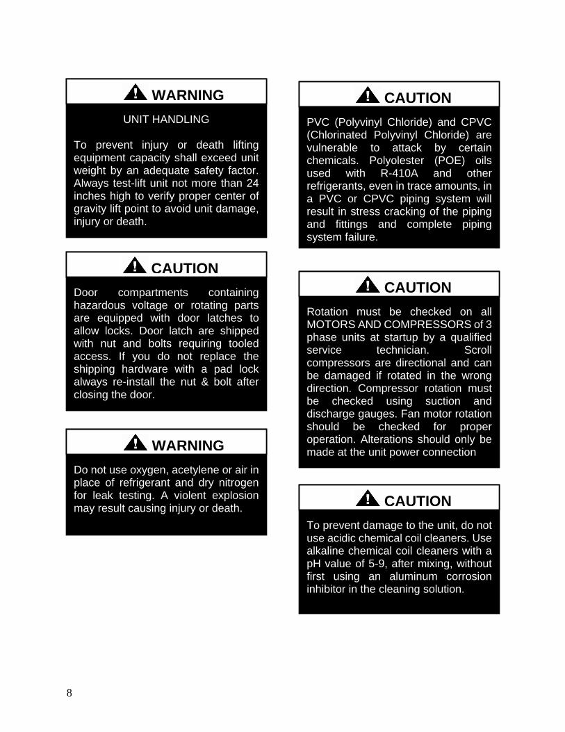
8
PVC (Polyvinyl Chloride) and CPVC (Chlorinated Polyvinyl Chloride) are vulnerable to attack by certain chemicals Polyolester (POE) oils used with R-410A and other refrigerants even in trace amounts in a PVC or CPVC piping system will result in stress cracking of the piping and fittings and complete piping system failure
CAUTION
UNIT HANDLING To prevent injury or death lifting equipment capacity shall exceed unit weight by an adequate safety factor Always test-lift unit not more than 24 inches high to verify proper center of gravity lift point to avoid unit damage injury or death
WARNING
Door compartments containing hazardous voltage or rotating parts are equipped with door latches to allow locks Door latch are shipped with nut and bolts requiring tooled access If you do not replace the shipping hardware with a pad lock always re-install the nut amp bolt after closing the door
CAUTION
Rotation must be checked on all MOTORS AND COMPRESSORS of 3 phase units at startup by a qualified service technician Scroll compressors are directional and can be damaged if rotated in the wrong direction Compressor rotation must be checked using suction and discharge gauges Fan motor rotation should be checked for proper operation Alterations should only be made at the unit power connection
CAUTION
Do not use oxygen acetylene or air in place of refrigerant and dry nitrogen for leak testing A violent explosion may result causing injury or death
WARNING
To prevent damage to the unit do not use acidic chemical coil cleaners Use alkaline chemical coil cleaners with a pH value of 5-9 after mixing without first using an aluminum corrosion inhibitor in the cleaning solution
CAUTION
9
1 Startup and service must be performed by
a Factory Trained Service Technician
2 The unit is for outdoor use only See
General Information section for more
information
3 Every unit has a unique equipment
nameplate with electrical operational
and unit clearance specifications Always
refer to the unit nameplate for specific
ratings unique to the model you have
purchased
4 READ THE ENTIRE INSTALLATION
OPERATION AND MAINTENANCE
MANUAL OTHER IMPORTANT
SAFETY PRECAUTIONS ARE
PROVIDED THROUGHOUT THIS
MANUAL
5 Keep this manual and all literature
safeguarded near or on the unit
Some chemical coil cleaning compounds are caustic or toxic Use these substances only in accordance with the manufacturerrsquos usage instructions Failure to follow instructions may result in equipment damage injury or death
WARNING
Do not clean DX refrigerant coils with hot water or steam The use of hot water or steam on refrigerant coils will cause high pressure inside the coil tubing and damage to the coil
CAUTION
Polyolester (POE) and Polyvinylether (PVE) oils are two types of lubricants used in hydrofluorocarbon (HFC) refrigeration systems Refer to the compressor label for the proper compressor lubricant type
CAUTION
COMPRESSOR CYCLING
3 MINUTE MINIMUM OFF TIME To prevent motor overheating compressors must cycle off for a minimum of 3 minutes
3 MINUTE MINIMUM ON TIME To maintain the proper oil level compressors must cycle on for a minimum of 3 minutes The cycle rate must not exceed 6 starts per hour
WARNING
10
LN Series Feature String Nomenclature
Model Options Unit Feature Options
GE
N
MJ
RE
V
SIZ
E
SE
RIE
S
MN
RE
V
VL
T
A1
A2
A3
A4
A5
B1
B2
B3
B4
1
2
3A
3B
3C
3D
4A
4B
4C
4D
5A
5B
5C
5D
6
7
8A
8B
8C
9
10A
10B
10C
10D
LN A ndash 140 ndash C ndash A ndash 3 ndash F A C 0 E ndash 0 0 0 0 A 0 ndash 0 0 0 0 ndash 0 0 0 0 ndash 0 0 0 0 ndash 0 0 ndash 0 0 0 ndash 0 ndash 0 E 0 0 ndash
0 0 0 0 0 ndash 0 A 0 0 0 ndash 0 0 0 0 0 ndash 0 0 0 0 0 0 ndash 0 0 0 0 0 ndash 0 0 0 B
11
12
13
14
15
16
17
18
19
20
21
22
23
24
25
26A
26B
26C
26D
26E
26F
27
28
29
30
31
32
33
34
35
MODEL OPTIONS SERIES AND GENERATION
LN
MAJOR REVISION
A
UNIT SIZE
045 = 45 ton Capacity
055 = 55 ton Capacity
060 = 60 ton Capacity
075 = 75 ton Capacity
095 = 95 ton Capacity
105 = 105 ton Capacity
120 = 120 ton Capacity
140 = 140 ton Capacity
SERIES
A = 45-60 ton units
B = 75 ton unit
C = 95-140 ton units
MINOR REVISION
A
VOLTAGE
2 = 230V3Φ60Hz
3 = 460V3Φ60Hz
4 = 575V3Φ60Hz
8 = 208V3Φ60Hz
A1 COMPRESSOR STYLE
F = R-410A Tandem VFD Compatible Scroll
Compressor
A2 CONDENSER STYLE
A = Air-Cooled Microchannel Condenser
A3 EVAPORATOR CONFIGURATION
A = Standard Brazed Plate Constant Flow
B = Oversized Brazed Plate Constant Flow
C = Standard Shell amp Tube Constant Flow
D = Oversized Shell amp Tube Constant Flow
A4 COATING
0 = Standard
E = Polymer E-Coated Condenser Coil
A5 STAGING
0 = Staged Compressors
E = All Circuits with Variable Capacity Compressors
- 2 Circuits
G = Half Circuits with Variable Capacity
Compressors - 2 Circuits
B1 BLANK
0 = Standard
B2 BLANK
0 = Standard
B3 BLANK
0 = Standard
B4 BLANK
0 = Standard
UNIT FEATURE OPTIONS 1 UNIT ORIENTATION
A = Standard Access Left Water Connections
B = Standard Access Right Water Connections
C = Standard Access Bottom Water Connections
2 PUMPING STYLE
0 = No Pumps
B = Constant Flow Primary Pumping System - Large
Pipe Size
D = Variable Flow Primary Pumping System - Large
Pipe Size
11
LN Series Feature String Nomenclature
Model Options Unit Feature Options
GE
N
MJR
EV
S
IZE
SE
RIE
S
MN
RE
V
VL
T
A1
A2
A3
A4
A5
B1
B2
B3
B4
1
2 3A
3B
3C
3D
4A
4B
4C
4D
5A
5B
5C
5D
6
7
8A
8B
8C
9
10A
10B
10C
10D
LN A ndash 140 ndash C ndash A ndash 3 ndash F A C 0 E ndash 0 0 0 0 A 0 ndash 0 0 0 0 ndash 0 0 0 0 ndash 0 0 0 0 ndash 0 0 ndash 0 0 0 ndash 0 ndash 0 E 0 0 ndash
0 0 0 0 0 ndash 0 A 0 0 0 ndash 0 0 0 0 0 ndash 0 0 0 0 0 0 ndash 0 0 0 0 0 ndash 0 0 0 B
11
12
13
14
15
16
17
18
19
20
21
22
23
24
25
26A
26B
26C
26D
26E
26F
27
28
29
30
31
32
33
34
35
3A BUILDING PUMP CONFIGURATION
0 = No Building Pumps
A = 1 Pump + High Eff Motor
B = 1 Dual Pump + High Eff Motors
D = 1 Pump + VFD + High Eff Motor
E = 1 Dual Pump + 2 VFDs + High Eff Motors
K = 1 Pump + Field Installed VFD + High Eff Motor
L = 1 Dual Pump + 2 Field Installed VFDs + High
Eff Motors
3B BUILDING PUMP SERIES AND RPM
0 = No Building Pumps
A = 4360 (1170 nominal rpm)
B = 4360 (1760 nominal rpm)
C = 4360 (3520 nominal rpm)
D = 4380 (1170 nominal rpm)
E = 4380 (1760 nominal rpm)
F = 4380 (3520 nominal rpm)
K = 4382 (1170 nominal rpm)
L = 4382 (1760 nominal rpm)
M = 4382 (3520 nominal rpm)
3C PUMP SIZE
0 = No Building Pumps
A = 15B
B = 2B
C = 2D
D = 3D
E = 15x15x6
F = 2x2x6
G = 3x3x6
H = 4x4x6
J = 6x6x6
K = 15x15x8
L = 2x2x8
M = 3x3x8
N = 4x4x8
P= 5x5x8
Q = 6x6x8
R = 8x8x8
S = 2x2x10
T = 3x3x10
U = 4x4x10
V = 6x6x10
W = 8x8x10
Y = 4x4x115
Z = 5x5x115
1 = 6x6x115
2 = 8x8x115
3 = 4x4x13
4 = 6x6x13
5 = 8x8x13
12
LN Series Feature String Nomenclature
GE
N
MJR
EV
S
IZE
SE
RIE
S
MN
RE
V
VL
T
A1
A2
A3
A4
A5
B1
B2
B3
B4
1
2
3A
3B
3C
3D
4
A
4B
4C
4D
5A
5B
5C
5D
6
7
8A
8B
8C
9
1
0A
10
B
10
C
10D
LN A ndash 140 ndash C ndash A ndash 3 ndash F A C 0 E ndash 0 0 0 0 A 0 ndash 0 0 0 0 ndash 0 0 0 0 ndash 0 0 0 0 ndash 0 0 ndash 0 0 0 ndash 0 ndash 0 E 0 0 -
0 0 0 0 0 ndash 0 A 0 0 0 ndash 0 0 0 0 0 ndash 0 0 0 0 0 0 ndash 0 0 0 0 0 ndash 0 0 0 B
11
12
13
14
15
16
17
18
19
20
21
22
23
24
25
26A
26B
26C
26D
26E
26F
27
28
29
30
31
32
33
34
35
3D BUILDING PUMP MOTOR SIZE
0 = No Building Pumps
C = 1 hp
E = 2 hp
F = 3 hp
G = 5 hp
H = 75 hp
J = 10 hp
K = 15 hp
L = 20 hp
M = 25 hp
N = 30 hp
P = 40 hp
Q = 50 hp
4A BLANK
0 = Standard
4B BLANK
0 = Standard
4C BLANK
0 = Standard
4D BLANK
0 = Standard
5A BLANK
0 = Standard
5B BLANK
0 = Standard
5C BLANK
0 = Standard
5D BLANK
0 = Standard
6 REFRIGERATION OPTIONS
0 = Standard
A = Hot Gas Bypass on Non-Variable Capacity
Circuits
B = Hot Gas Bypass - All Circuits
7 REFRIGERATION ACCESSORIES
0 = Standard
A = Sight Glass
B = Compressor Isolation Valves
C = Option A + B
8A UNIT DISCONNECT TYPE
0 = Standard Single Point Power Block
A = Single Point Power Non-fused Disconnect
8B DISCONNECT SIZE
0 = Power Block
N = 100 amps
R = 150 amps
U = 225 amps
V = 250 amps
Z = 400 amps
3 = 600 amps
5 = 800 amps
7 = 1200 amps
8C BLANK
0 = Standard
9 ACCESSORIES
0 = Standard
B = Phase amp Brown Out Protection
10A UNIT CONTROL SEQUENCE
0 = Standard Controls
10B UNIT CONTROL SUPPLIER
E = MCS Controls
10C CONTROL SUPPLIER OPTIONS
0 = Standard
A = Touchscreen Interface
C = Modem
G = Option A + C
Model Options Unit Feature Options
13
LN Series Feature String Nomenclature
Model Options Unit Feature Options
GE
N
MJR
EV
S
IZE
SE
RIE
S
MN
RE
V
VL
T
A1
A2
A3
A4
A5
B1
B2
B3
B4
1
2
3A
3B
3C
3D
4A
4B
4C
4D
5A
5B
5C
5D
6
7
8A
8B
8C
9
10A
10B
10C
10
D
LN A ndash 140 ndash C ndash A ndash 3 ndash F A C 0 E ndash 0 0 0 0 A 0 ndash 0 0 0 0 ndash 0 0 0 0 ndash 0 0 0 0 ndash 0 0 ndash 0 0 0 ndash 0 ndash 0 E 0 0 ndash
0 0 0 0 0 ndash 0 A 0 0 0 ndash 0 0 0 0 0 ndash 0 0 0 0 0 0 ndash 0 0 0 0 0 ndash 0 0 0 B
11
12
13
14
15
16
17
18
19
20
21
22
23
24
25
26
A
26
B
26
C
26D
26E
26F
27
28
29
30
31
32
33
34
35
10D BMS CONNECTION amp DIAGNOSTICS
0 = None
A = BACnet IP
B = BACnet MSTP
C = Modbus IP
D = Modbus RTU
E = Lontalk
H = No BMS Connection with Diagnostics
J = BACnet IP with Diagnostics
K = BACnet MSTP with Diagnostics
L = Modbus IP with Diagnostics
M = Modbus RTU with Diagnostics
N = Lontalk with Diagnostics
11 BLANK
0 = Standard
12 VESTIBULE ACCESSORIES
0 = Standard
C = Vestibule Heating (Electric)
13 MAINTENANCE ACCESSORIES
0 = Standard
A = 115VAC Convenience Outlet Factory Wired
B = 115VAC Convenience Outlet Field Wired
C = Service Lights
F = Options A + C
J = Options B + C
14 BLANK
0 = Standard
15 CODE OPTIONS
0 = Standard ETL USA Listing
A = Chicago Code
B = ETL USA + Canada Listing
16 SHIPPING SPLITS
0 = One Piece Unit
17 AIR-COOLED CHILLER ACCESSORIES
H = Cond Coil Guards + Three Phase Cond Fan
Motor + Fan Cycling- 35degF Low Ambient
J = Cond Coil Guards + VFD Cond Fan Head
Pressure Control - 0degF Low Ambient
18 BLANK
0 = Standard
19 BLANK
0 = Standard
20 BLANK
0 = Standard
21 BLANK
0 = Standard
22 BLANK
0 = Standard
23 BLANK
0 = Standard
24 CHILLER ACCESSORIES 1
0 = Standard
A = Glycol Chiller
C = Thermometers amp Pressure Gauges
G = Option A + C
25 BLANK
0 = Standard
26A BLANK
0 = Standard
26B BLANK
0 = Standard
26C BLANK
0 = Standard
14
LN Series Feature String Nomenclature
Model Options Unit Feature Options
GE
N
MJR
EV
S
IZE
SE
RIE
S
MN
RE
V
VL
T
A1
A2
A3
A4
A5
B1
B2
B3
B4
1
2
3A
3B
3C
3D
4A
4B
4C
4D
5A
5B
5C
5D
6
7
8A
8B
8C
9
10A
10B
10C
10D
LN A ndash 140 ndash C ndash A ndash 3 ndash F A C 0 E ndash 0 0 0 0 A 0 ndash 0 0 0 0 ndash 0 0 0 0 ndash 0 0 0 0 ndash 0 0 ndash 0 0 0 ndash 0 ndash 0 E 0 0 ndash
0 0 0 0 0 ndash 0 A 0 0 0 ndash 0 0 0 0 0 ndash 0 0 0 0 0 0 ndash 0 0 0 0 0 ndash 0 0 0 B
11
12
13
14
15
16
17
18
19
20
21
22
23
24
25
26A
26B
26C
26
D
26
E
26
F
27
28
29
30
31
3
2
33
34
35
26D BLANK
0 = Standard
26E BLANK
0 = Standard
26F BLANK
0 = Standard
27 BLANK
0 = Standard
28 BLANK
0 = Standard
29 BLANK
0 = Standard
30 BLANK
0 = Standard
31 BLANK
0 = Standard
32 BLANK
0 = Standard
33 WARRANTY
0 = Standard Warranty
D = Compressor Warranty Years 2-5
34 CABINET MATERIAL
0 = Standard - Double Wall + R-13 Foam Insulation
35 PAINT amp SPECIAL PRICING
AUTHORIZATIONS
B = Premium AAON Gray Paint Exterior
E = Premium AAON Gray Paint Exterior + Shrink
Wrap
X = Special Pricing Authorization + Premium AAON
Gray Paint Exterior
1 = SPA + Premium AAON Gray Paint Exterior +
Shrink Wrap
4 = Special Pricing Authorization + Special Exterior
Paint Color
7 = SPA + Special Exterior Paint Color + Shrink
Wrap
15
General Information
AAON LN Series chillers are complete self-
contained liquid chilling units They are
assembled wired charged and run-tested
Models are available for air-cooled
applications Chiller primary pumping
packages are available as optional features
Codes and Ordinances
LN Series units have been tested and
certified by ETL in accordance with UL
Safety Standard 1995CSA C222 No 236
System should be sized in accordance with
the American Society of Heating
Refrigeration and Air Conditioning
Engineers Handbook
Installation of LN Series units must conform
to the ICC standards of the International
Mechanical Code the International Building
Code and local building plumbing and
waste water codes All appliances must be
electrically grounded in accordance with
local codes or in the absence of local codes
the current National Electric Code
ANSINFPA 70 or the current Canadian
Electrical Code CSA C221
Receiving Unit
When received the unit should be checked
for damage that might have occurred in
transit If damage is found it should be noted
on the carrierrsquos Freight Bill A request for
inspection by carrierrsquos agent should be made
in writing at once Nameplate should be
checked to ensure the correct model sizes and
voltages have been received to match the job
requirements
If repairs must be made to damaged goods
then the factory should be notified before any
repair action is taken in order to protect the
warranty Certain equipment alteration
repair and manipulation of equipment
without the manufacturerrsquos consent may void
the product warranty Contact AAON
Technical Support for assistance with
Improper installation adjustment alteration service or maintenance can cause property damage personal injury or loss of life Startup and service must be performed by a Factory Trained Service Technician
WARNING
The Clean Air Act of 1990 bans the intentional venting of refrigerant as of July 1 1992 Approved methods of recovery recycling or reclaiming must be followed
CAUTION
Coils and sheet metal surfaces present sharp edges and care must be taken when working with equipment
Failure to observe the following instructions will result in premature failure of your system and possible voiding of the warranty
WARNING
WARNING
16
handling damaged goods repairs and freight
claims (918) 382-6450
Storage
If installation will not occur immediately
following delivery store equipment in a dry
protected area away from construction traffic
and in the proper orientation as marked on the
packaging with all internal packaging in
place Secure all loose-shipped items
Chiller
Failure to observe the following instructions
will result in premature failure of your
system and possible voiding of the warranty
Never turn off the main power supply to the
unit except for complete shutdown When
power is cut off from the unit any
compressors using crankcase heaters cannot
prevent refrigerant migration This means the
compressor will cool down and liquid
refrigerant may accumulate in the
compressor The compressor is designed to
pump refrigerant gas and damage may occur
when power is restored if liquid enters the
compressor
Before unit operation the main power switch
must be turned on for at least 24 hours for
units with compressor crankcase heaters
This will give the crankcase heater time to
clear any liquid accumulation out of the
compressor before it is required to run
Rotation must be checked on all MOTORS AND COMPRESSORS of three phase units All motors to include and not be limited to pump motors and condenser fan motors should all be checked by a qualified service technician at startup and any wiring alteration should only be made at the unit power connection
CAUTION
Scroll compressors are directional and will be damaged by operation in the wrong direction Low pressure switches on compressors have been disconnected after factory testing Rotation should be checked by a qualified service technician at startup using suction and discharge pressure gauges and any wiring alteration should only be made at the unit power connection
CAUTION
CRANKCASE HEATER OPERATION
Units may be equipped with compressor crankcase heaters which should be energized at least 24 hours prior to cooling operation to clear any liquid refrigerant from the compressors
CAUTION
COMPRESSOR CYCLING
3 MINUTE MINIMUM OFF TIME To prevent motor overheating compressors must cycle off for a minimum of 3 minutes
3 MINUTE MINIMUM ON TIME To maintain the proper oil level compressors must cycle on for a minimum of 3 minutes The cycle rate must not exceed 6 starts per hour
WARNING
17
Never cut off the main power supply to the
unit except for complete shutdown Always
control the system from the building
management system or control panel never
at the main power supply (except for
emergency or for complete shutdown of the
system)
Scroll compressors must be on a minimum of
3 minutes and off for a minimum of 3
minutes The cycle rate must be no more than
6 starts per hour
The chiller is furnished with a pressure
differential switch that is factory installed
between the chilled water supply and return
connections This sensor must not be
bypassed since it provides a signal to the unit
controller that water flow is present in the
heat exchanger and the unit can operate
without the danger of freezing the liquid
Compressor life will be seriously shortened
by reduced lubrication and the pumping of
excessive amounts of liquid oil and liquid
refrigerant
Wiring Diagrams
A complete set of unit specific wiring
diagrams in both ladder and point-to-point
form are laminated in plastic and located
inside the control compartment door
General Maintenance
When the initial startup is made and on a
periodic schedule during operation it is
necessary to perform routine service checks
on the performance of the chiller This
includes reading and recording suction
pressures and checking for normal sub-
cooling and superheat See the air-cooled
condenser sections in this manual for specific
details
Chiller Primary Pumping
Primary pumping uses a single pump to move
water (or glycol) through the chiller barrel
and back to the building This pumping
package provides a constant or variable flow
of water to the system The pump is activated
whenever the chiller is given a run signal
Water enters the unit through the return water
piping and then travels through an air
separator to remove any air that is entrapped
in the water Following this the water flows
through a suction guide with strainer The
end of the suction guide is removable for
strainer access The strainer assembly is
composed of two parts the operational
strainer and the startup strainer (located
inside the operational strainer) which is to be
removed 24 hours after startup
The pump is installed after the suction guide
and before a combination valve (Flo-Trex)
This combination valve acts as isolation
valve check valve and flow balancing valve
The shell and tube or brazed plate evaporator
is placed after the combination valve in the
water circuit with a flow switch installed
across its inlet and outlet This flow switch
closes when the velocity is above 07 feet per
second The closing flow switch signals the
control system to indicate flow through the
heat exchanger and allow cooling to activate
as required to maintain the setpoint The
water exiting the chiller evaporator leaves the
unit through the water out connection
18
Automatic Air Vent
There is an automatic air vent installed at the
high point of the system inside the pumping
package compartment The air vent valve
must be in the proper position for operation
Ensure that the small vent cap is loosened two
turns from the closed position allowing air to
be vented from the system It is advisable to
leave the cap on to prevent impurities from
entering the valve See appendix for
additional information
Dual Pumps
When redundant pumping is required factory
installed dual pumps can be ordered A dual
pump is a pump with two independent motors
and pumps in a single casing This dual pump
has a swing split-flapper valve in the
discharge port to prevent liquid recirculation
when only one pump is operating Isolation
valves in the casing allow one pump to be
isolated and removed for service while the
other pump is still operating
The controls package will activate the pump
when the unit is given a run command If the
controls do not recognize flow in 60 seconds
the second pump will be activated and an
alarm signal will be generated If the second
pump does not activate the cooling will be
locked out See appendix for additional
information
Pressure Gauges and Thermometers
Pressure gauges and thermometers are
available as a factory installed option
Thermometers are installed on the inlet and
outlet of the unit One pressure gauge is
installed at each pump This pressure gauge
is connected in three places to the water
piping before the suction guidestrainer after
the suction guide and before the pump and
after the pump There is also a needle valve
at each of these points to isolate the pressure
To measure the pressure at any given point
open the needle valve at that point and close
the other two needle valves One gauge is
used so that the calibration of the pressure
gauge is irrelevant in the calculation of the
differential pressure
Pipe Insulation
The water piping and components on units
with pumping packages are not insulated at
the factory Insulation should be installed on
the water piping after the system has been
checked for leaks
19
Installation
Chiller Placement
The AAON LN Series is designed for
outdoor applications and mounting at ground
level or on a rooftop It must be placed on a
level and solid foundation that has been
prepared to support its weight
The placement relative to the building air
intakes and other structures must be carefully
selected Be sure to observe the dimensions
that are on the rating plate of the chiller for
operational and service clearances
Table 1 - Service Clearances
Location Unit Size
45-140 tons
Front -
(Controls Side) 72rdquo
Back 72rdquo
Ends 96rdquo
Top Unobstructed
Condenser coils and fans must be free of any
obstructions in order to start and operate
properly with a correct amount of airflow
For proper unit operation the immediate area
around condenser must remain free of debris
that may be drawn in and obstruct airflow in
the condensing section
Consideration must be given to obstruction
caused by snow accumulation when placing
the unit
Curb and Steel Mount Installation
Make openings in the roof decking large
enough to allow for water piping electrical
penetrations and workspace only Do not
make openings larger than necessary Set the
curb to coincide with the openings Make
sure curb is level
If the LN is installed on a curb use a curb cap
for the open area under the condenser section
Unit specific curb drawing is included with
job submittal See SMACNA Architectural
Sheet Metal Manual for curb installation
details
Units require rail support along all four sides
of the unit base
When installed at ground level a one-piece
concrete slab should be used with footings
that extend below the frost line Care must
also be taken to protect the coil and fins from
damage due to vandalism or other causes
If unit is elevated a field supplied catwalk is
recommended to allow access to unit service
doors
This unit ships with a curb gasket that is 1frac14rdquo
wide and 1frac12rdquo tall It is recommended that this
or another similar gasket be used between the
curb and the unit to reduce vibration from the
unit to the building
All roofing work should be performed by competent roofing contractors to avoid any possible leakage
CAUTION
Figure 1 - LN Base
20
Figure 2 - Curb Mounting with Dimensions
Figure 3 - Steel Mounting Rail with
Dimensions
Table 2 - Mounting Dimensions
Tons A B C D
45-140 142rdquo 138rdquo 134rdquo 139rdquo
Figure 2
Figure 3
Lifting and Handling
If cables or chains are used to hoist the unit
they must be the same length and care should
be taken to prevent damage to the cabinet
See Figure 5 and Figure 6 for additional
information
Before lifting unit be sure that all shipping
material has been removed from unit Secure
hooks and cables at all lifting points lugs
provided on the unit
Hoist unit to a point directly above the curb
or mounting rail Be sure that the gasket
material has been applied to the curb or
mounting rail
Carefully lower and align unit with utility and
duct openings Lower the unit until the unit
skirt fits around the curb Make sure the unit
is properly seated on the curb and is level
Figure 4 - Lifting Points
21
Figure 5 - Lifting Detail of a 45-60 ton Unit
Figure 6 - Lifting Detail of a 75-140 ton Unit
Lifting slot locations are unit specific
Unit must be rigged at all marked lifting points
22
Water Connection
Connect the supply and return water lines
The connection size is listed on the unit rating
sheet along with the designed volumetric
flow rate The maximum operating pressure
for AAON LN Series units is 125 psi
Mounting Isolation
For roof mounted applications or anytime
vibration transmission is a factor vibration
isolators may be used
Access Doors
Lockable access door is provided to the
compressor and control compartment A
separate access door is also provided to the
pumping package compartment
A light switch with service lights is provided
on the wall of the compressor and control
compartment
End Flashing Installation
On all LN Series units the cabinet width will
overhang the shipping trailer on each side
In order to secure and protect the unit during
transit the sheet metal end flashings have
been removed from the unit The slot created
at the base of each end of the unit allows the
unit to set firmly on the trailer deck
Sheet metal flashings are shipped loose with
the unit and once the unit is set into place the
flashings must be installed on each end of the
unit to complete the finished seal at the base
The flashings are unit specific and designed
to cover the slot at each end of the unit to
prevent water run-off into the curb
Failure to attach and seal the end of unit with
the flashings may result in water leakage into
the curb
Figure 7 - Factory Supplied End Flashings
PVC (Polyvinyl Chloride) and CPVC (Chlorinated Polyvinyl Chloride) are vulnerable to attack by certain chemicals Polyolester (POE) oils used with R-410A and other refrigerants even in trace amounts in a PVC or CPVC piping system will result in stress cracking of the piping and fittings and complete piping system failure
CAUTION
The chiller must be operated only with liquid flowing through the evaporators
WARNING
Installing Contractor is responsible for proper sealing of the water piping entries into the unit Failure to seal the entries may result in damage to the unit and property
CAUTION
23
Low Ambient Operation
If the chiller is ordered for a Low Ambient
application the liquid system must use a
glycol solution and the piping must be
insulated to be prepared for freezing
conditions Care must be taken in the source
of electrical power for the heating tape and
thermostat
Electrical
The single point electrical power connections
are made in the electrical control
compartment
The microprocessor control furnished with
the unit is supplied with its own power supply
factory wired to the main power of the
outdoor mechanical room
Verify the unit nameplate voltage agrees with
the power supply Connect power and control
field wiring as shown on the unit specific
wiring diagram provided with the unit
Size supply conductors based on the unit
MCA rating Supply conductors must be
rated a minimum of 167degF (75degC)
Route power and control wiring separately
through the utility entry Do not run power
and signal wires in the same conduit
Protect the branch circuit in accordance with
code requirements The unit must be
electrically grounded in accordance with
local codes or in the absence of local codes
the current National Electric Code
ANSINFPA 70 or the current Canadian
Electrical Code CSA C221
Power wiring is to the unit terminal block or
main disconnect All wiring beyond this point
has been done by the manufacturer and
cannot be modified without effecting the
units agencysafety certification
Figure 8 - Front View of Utility Entry and
Power Switch from Control Compartment
Electric shock hazard Before attempting to perform any installation service or maintenance shut off all electrical power to the unit at the disconnect switches Unit may have multiple power supplies Failure to disconnect power could result in dangerous operation serious injury death or property damage
WARNING
In order to prevent water leakage into the roof curb the factory provided sheet metal flashings MUST BE attached to the unit base to cover the shipping slots at both ends of the unit
CAUTION
24
Startup technician must check for proper
motor rotation and check fan motor amperage
listed on the motor nameplate is not
exceeded Motor overload protection may be
a function of the variable frequency drive and
must not be bypassed
Note All units are factory wired for
208230V 460V or 575V If unit is to be
connected to a 208V supply the transformer
must be rewired to 208V service For 208V
service interchange the yellow and red
conductor on the low voltage control
transformer
Red-Black for 208V
Yellow-Black for 230V
Wire control signals to the unitrsquos low voltage
terminal block located in the controls
compartment All wiring beyond this point
has been completed by the manufacturer and
cannot be modified without effecting the
unitrsquos agencysafety certification
If any factory installed wiring must be
replaced use a minimum 221degF (105degC) type
AWM insulated conductors
Supply voltage must be within the minmax
range shown on the unit nameplate Available
short circuit current should not exceed the
short circuit current rating (SCCR) shown on
the unit nameplate
Three phase voltage imbalance will cause
motor overheating and premature failure
The maximum allowable imbalance is 5
Voltage imbalance is defined as 100 times the
maximum deviation from the average voltage
divided by the average voltage
Example
(218V+237V+235V)3 = 230V then
100(230V-218V)230V = 52 which
exceeds the allowable imbalance
Check voltage imbalance at the unit
disconnect switch and at the compressor
terminal Contact your local power company
for line voltage corrections
Three phase voltage imbalance will cause motor overheating and premature failure
CAUTION
Scroll compressors are directional and will be damaged by operation in the wrong direction Low pressure switches on compressors have been disconnected after factory testing Rotation should be checked by a qualified service technician at startup using suction and discharge pressure gauges and any wiring alteration should only be made at the unit power connection
Installing Contractor is responsible for proper sealing of the electrical and gas entries into the unit Failure to seal the entries may result in damage to the unit and property
CAUTION CAUTION
25
Variable Speed Compressors
Variable speed compressors should not be
operated outside the factory determined
frequency range The factory determined
compressor VFD frequency range is given
below in Table 3
Table 3- Tandem Circuited Variable Speed
Compressor VFD Frequency Range
Model (LN-) Compressor VFD
Range (Hz)
208V 230V 460V and 575V Units
045 055 060 45-65Hz
075 45-70Hz
095 105 120 35-60 Hz
140 35-65 Hz
No variable speed compressor shall operate below 35 Hz Operating variable speed compressors outside the frequency range specified in this manual voids all warranties and may result in compressor failure
CAUTION
Rotation must be checked on all MOTORS AND COMPRESSORS of three phase units Condenser fan motors should all be checked by a qualified service technician at startup and any wiring alteration should only be made at the unit power connection Variable frequency drives are programmed to automatically rotate the fan in the correct rotation Do not rely on fans with variable frequency drives for compressor rotation
CAUTION
26
Startup (See back of the manual for startup form)
Before the startup of the chiller be sure that
the following items have been checked
1 Verify that electrical power is available to
the unit
2 Verify that any remote stopstart device
connected to the chiller controller is
requesting the chiller to start
3 Verify that liquid flow is present through
the chiller from the building
4 There should be a building load of at least
25 of the chiller capacity in order to
properly check operation
5 With the main power switch off review
the MCS Controller Manual provided
with the chiller Understand the keypad
functions how to set the leaving water
temperature setpoint and how to initiate
the Run State
Use the general check list at the top of the
startup form to make a last check that all the
components are in place water flow is
present and the power supply is energized
Using the controller keypad individually set
the outputs in ldquoManual Onrdquo to confirm relay
closure and compressor operation
Cycle through all the compressors to confirm
that all are operating within tolerance
While performing the check use the startup
form to record observations of compressor
amps and refrigerant pressures
When all is running properly place the
controller in the Run mode and observe the
system until it reaches a steady state of
operation
Note For more information on programming
the controller refer to the MCS Controller
manual provided with the chiller
Electric shock hazard Shut off all electrical power to the unit to avoid shock hazard or injury from rotating parts
WARNING
Improper installation adjustment alteration service or maintenance can cause property damage personal injury or loss of life Startup and service must be performed by a Factory Trained Service Technician
WARNING
Rotation must be checked on all MOTORS AND COMPRESSORS of three phase units All motors to include and not be limited to pump motors and condenser fan motors should all be checked by a qualified service technician at startup and any wiring alteration should only be made at the unit power connection
CAUTION
Before completing installation a complete operating cycle should be observed to verify that all components are functioning properly
CAUTION
27
Axial Flow Condenser Fans
Multi-Wing Z Series Aluminum Fan Blade
Pitch Angle Setting Instructions
1 Maintain the balance of fan
Mark the hub castings across a joint so the
fan hub can be reassembled in the same
orientation
Mark the location of any balancing weight
Balancing weight will be on the outer bolt
circle in the form of washers andor longer
bolts or an additional balancing nut
Number the blades and blade sockets so that
they are replaced into their original position
Figure 9 - Fan with the HUB on the top and
RET on the bottom
2 Determine the direction of rotation
Right R is clockwise when facing the
discharge side of the fan and Left L is
counterclockwise when facing the discharge
side of the fan
3 Determine the bushing mount location
The bushing mount is the center section of the
hub through which the fan is mounted to the
shaft and typically contains either setscrews
or a center-tapered hole where the bushing
inserts
Location A is with the bushing mount on air
inlet side of the fan
Location B is with the bushing mount on air
discharge side of the fan
Figure 10 - Bushing Mount Location
4 Determine the pin location groove
Disassemble fan on a flat surface and note in
which groove the pin is located
Figure 11 - RET with Pin in Groove 4
Bushing
Mount
A B Bushing
Mount
Bushing Bushing
1 2 3 4
28
5 Determine whether the pin is in the HUB
or RET
Figure 12 - Fan HUB and RET Castings
6 Determine the current blade pitch and the pin location for the new blades
Table 4 - ReturnExhaust Fan Pin Location
Type Bushing
Mount
Blade Pitch Angle
20deg 25deg 28deg 30deg 33deg 35deg 38deg 40deg 45deg 50deg
5Z A - RET - RET RET RET HUB HUB HUB HUB
B - HUB - HUB HUB HUB RET RET RET RET
Table 5 - ReturnExhaust Fan Pin Location
Type Rot Blade Pitch Angle
20deg 25deg 28deg 30deg 33deg 35deg 38deg 40deg 45deg 50deg
5Z R - 4 - 3 2 1 4 3 2 1
L - 1 - 2 3 4 1 2 3 4
7 Replace fan blades in the new pin
location and reassemble the fan
Replace the blades with the pin in the 1 2 3
or 4 groove position of either the HUB or
RET Assemble the fan making sure to place
the blades in their previous blade sockets to
match up the previous orientation of HUB
and RET and to replace any balancing
weights in their previous locations Tighten
bolts in a cross pattern to 5-6 ft-lbs of torque
29
Multi-Wing W Series Black Glass
Reinforced Polypropylene Fan Blade Pitch
Angle Setting Instructions
Contact the AAON parts department to
acquire the new pitch pins for the fan blades
Note original position of retaining plates
center boss and all hardware including
additional hardware used for balancing
1 Remove all the bolts and nuts
2 Determine blade rotation ndash on the concave
side of the blade is a blade marking showing
6WR 6WL 7WL 7WR or 9WR The ldquoLrdquo
and ldquoRrdquo denote the rotation of the blade
3 Replace the pitch insert in the blade root
with an insert of the desired pitch
Figure 13 - Pitch Insert
4 Replace blades to their original location
5 Replace all nuts bolts and washers on the
fan hub
6 Replace retaining plates and center boss to
original location
7 Tighten nuts and bolts to 14 ft-lbs of
torque
Fan Assembly Bushings
The fan assembly bushings should be
tightened to the specifications listed in the
following table
Table 6 - Fan Assembly Bushing Torque
Specifications
Bushing Tightening Torque
(in-lbs)
H X 1125 95
H X 1375 95
SH X 1125 108
SH X 1375 108
SD X 1125 108
SD X 1375 108
SD X 1625 108
SD X 1875 108
SK X 2125 180
30
Maintenance
General
Qualified technicians must perform routine
service checks and maintenance This
includes reading and recording the
condensing and suction pressures and
checking for normal sub-cooling and
superheat
Air-cooled chillers require maintenance
schedulesprocedures Unit specific
instructions are included in this manual
Compressors
The scroll compressors are fully hermetic and
require no maintenance except keeping the
shell clean
Refrigerant Suction Line Filter
Each refrigerant circuit contains a
replaceable core suction line filter One
month after start-up remove the filter
element
The replaceable core suction filters are
provided with pressure taps and shutoff
valves for isolation when removing the filter
For safety purposes a service manifold must
be attached prior to filter maintenance
Suction Filter Removal Instructions
1 Shut down operation of the unit
2 Close both shut-off valves to isolate
the suction filter
3 Reclaim the refrigerant from the
suction filter section
4 Remove the bolts from the suction
filter end plate
5 Remove the pleated filter assembly
Prior to filter core service a service manifold MUST BE attached to in and out pressure connections to assure no pressure exists during filter maintenance Non-compliance could result in injury or violation of EPA regulations
Service gauges MUST BE connected before operating the isolation valves for the replaceable core filter
WARNING
WARNING
31
6 Replace the suction filter end plate
and bolts
7 Evacuate the suction filter assembly
to 500 microns
8 Open both shut-off valves
Adjusting Refrigerant Charge
All AAON chillers are shipped with a full
factory charge Periodically adjusting the
charge of a system may be required
Adjusting the charge of a system in the field
must be based on determination of liquid sub-
cooling and evaporator superheat On a
system with an expansion valve liquid sub-
cooling is more representative of the charge
than evaporator superheat but both
measurements must be taken
Before Charging
Refer to the unit nameplate as a reference
when determining the proper refrigerant
charge
Unit being charged must be at or near full
load conditions before adjusting the charge
Units equipped with hot gas bypass must
have the hot gas bypass valve closed to get
the proper charge
After adding or removing charge the system
must be allowed to stabilize typically 10-15
minutes before making any other
adjustments
The type of unit and options determine the
ranges for liquid sub-cooling and evaporator
superheat Refer to Table 7 when determining
the proper sub-cooling
For units equipped with low ambient (0degF)
option see the special charging instructions at
the end of this section
Checking Liquid Sub-cooling
Measure the temperature of the liquid line as
it leaves the condenser coil
Read the gauge pressure at the liquid line
close to the point where the temperature was
taken You must use liquid line pressure as it
will vary from discharge pressure due to
condenser coil pressure drop
Convert the pressure obtained to a saturated
temperature using the appropriate refrigerant
temperature-pressure chart
Subtract the measured liquid line temperature
from the saturated temperature to determine
the liquid sub-cooling
Compare calculated sub-cooling to the table
below for the appropriate unit type and
options
The Clean Air Act of 1990 bans the intentional venting of refrigerant (CFCrsquos and HCFCrsquos) as of July 1 1992 Approved methods of recovery recycling or reclaiming must be followed Fines andor incarceration may be levied for non-compliance
CAUTION
Polyolester (POE) and Polyvinylether (PVE) oils are two types of lubricants used in hydrofluorocarbon (HFC) refrigeration systems Refer to the compressor label for the proper compressor lubricant type
CAUTION
32
Checking Evaporator Superheat
Measure the temperature of the suction line
close to the compressor
Read gauge pressure at the suction line close
to the compressor
Convert the pressure obtained to a saturated
temperature using the appropriate refrigerant
temperature-pressure chart
Subtract the saturated temperature from the
measured suction line temperature to
determine the evaporator superheat
For refrigeration systems with tandem scroll
compressors it is critical that the suction
superheat setpoint on the expansion valve is
set with one compressor running The suction
superheat should be 10-13degF with one
compressor running The suction superheat
will increase with both compressors in a
tandem running Inadequate suction
superheat can allow liquid refrigerant to
return to the compressors which will wash the
oil out of the compressor Lack of oil
lubrication will destroy a compressor Liquid
sub-cooling should be measured with both
compressors in a refrigeration system
running
Compare calculated superheat to Table 7 for
the appropriate unit type and options
Table 7 - Acceptable Refrigeration Circuit
Values
Air-Cooled Chiller with Scroll
Compressors
Sub-Cooling2 12-18degF
Superheat1 10-15degF 1 One compressor running in tandem 2 Two compressors running in tandem
Adjusting Sub-cooling and Superheat
Temperatures
The system is overcharged if the sub-cooling
temperature is too high and the evaporator is
fully loaded (low loads on the evaporator
result in increased sub-cooling) and the
evaporator superheat is within the
temperature range as shown in Table 7 (high
superheat results in increased sub-cooling)
Correct an overcharged system by reducing
the amount of refrigerant in the system to
lower the sub-cooling
The system is undercharged if the superheat
is too high and the sub-cooling is too low
Correct an undercharged system by adding
refrigerant to the system to reduce superheat
and raise sub-cooling
If the sub-cooling is correct and the superheat
is too high the expansion valve may need
adjustment to correct the superheat
Expansion valves must be adjusted to approximately 10-15degF of suction superheat Failure to have sufficient superheat will damage the compressor and void the warranty
CAUTION
DO NOT OVERCHARGE Refrigerant overcharging leads to excess refrigerant in the condenser coils resulting in elevated compressor discharge pressure
CAUTION
33
Table 8 - R-410A Refrigerant Temperature-Pressure Chart
F psig F psig F psig F psig F psig
20 783 50 1422 80 2349 110 3641 140 5401
21 800 51 1448 81 2386 111 3691 141 5470
22 818 52 1474 82 2423 112 3742 142 5539
23 836 53 1501 83 2460 113 3794 143 5609
24 854 54 1528 84 2498 114 3846 144 5679
25 872 55 1555 85 2537 115 3899 145 5751
26 891 56 1582 86 2575 116 3952 146 5823
27 910 57 1610 87 2614 117 4005 147 5896
28 929 58 1638 88 2654 118 4059 148 5969
29 949 59 1667 89 2694 119 4114 149 6044
30 968 60 1696 90 2735 120 4169 150 6119
31 988 61 1725 91 2776 121 4225
32 1009 62 1754 92 2817 122 4282
33 1029 63 1784 93 2859 123 4339
34 1050 64 1815 94 2901 124 4396
35 1071 65 1845 95 2944 125 4454
36 1092 66 1876 96 2987 126 4513
37 1114 67 1907 97 3030 127 4573
38 1136 68 1939 98 3075 128 4632
39 1158 69 1971 99 3119 129 4693
40 1181 70 2004 100 3164 130 4754
41 1203 71 2036 101 3210 131 4816
42 1227 72 2070 102 3256 132 4878
43 1250 73 2103 103 3302 133 4941
44 1274 74 2137 104 3349 134 5005
45 1298 75 2171 105 3396 135 5069
46 1322 76 2206 106 3444 136 5134
47 1347 77 2241 107 3493 137 5200
48 1372 78 2277 108 3542 138 5266
49 1397 79 2313 109 3591 139 5333
34
Lubrication
All original motors and bearings are
furnished with an original factory charge of
lubrication Certain applications require
bearings be re-lubricated periodically The
schedule will vary depending on operating
duty temperature variations or severe
atmospheric conditions
Bearings should be re-lubricated at normal
operating temperatures but not when
running
Rotate the fan shaft by hand and add only
enough grease to purge the seals DO NOT
OVERLUBRICATE
Air-Cooled Condenser
The air-cooled condenser section rejects heat
by passing outdoor air over the fin tube coils
for cooling of the hot refrigerant gas from the
compressors The heated air will discharge
from the top of the section through the axial
flow fans
The condenser coils should be inspected
yearly to ensure unrestricted airflow If the
installation has a large amount of airborne
dust or other material the condenser coils
should be cleaned according to the
microchannel coil cleaning section
Brazed Plate Heat Exchanger Cleaning
Because of a normally high degree of
turbulence in brazed plate heat exchangers
for many applications the heat exchanger
channels are self-cleaning For applications
that are not self-cleaning (ie hard water at
high temperatures etc) or applications where
additional cleaning is desired it is possible to
clean the brazed plate heat exchanger by
circulating a cleaning liquid
Use a tank with weak acid 5 phosphoric
acid (H3PO4) or if the exchanger is
frequently cleaned 5 oxalic acid (H2C2O4)
Pump the cleaning liquid through the
exchanger For optimum cleaning the
cleaning solution flow rate should be a
minimum of 15 times the normal flow rate
preferably in a back-flush mode After
cleaning the heat exchanger must be rinsed
with clean water A solution of 1-2 sodium
hydroxide (NaOH) or sodium bicarbonate
(NaHCO) before the last rinse ensures that all
acid is neutralized
E-Coated Coil Cleaning
Documented quarterly cleaning of e-coated
coils is required to maintain coating warranty
coverage
Surface loaded fibers or dirt should be
removed prior to water rinse to prevent
restriction of airflow If unable to back wash
the side of the coil opposite of the coils
entering air side then surface loaded fibers or
dirt should be removed with a vacuum
cleaner If a vacuum cleaner is not available
a soft non-metallic bristle brush may be used
In either case the tool should be applied in
the direction of the fins Coil surfaces can be
easily damaged (fin edges bent over) if the
tool is applied across the fins
Use of a water stream such as a garden hose
against a surface loaded coil will drive the
fibers dirt and salts into the coil This will
make cleaning efforts more difficult Surface
loaded fibers must be completely removed
prior to using low velocity clean water rinse
Electric shock hazard Shut off all electrical power to the unit to avoid shock hazard or injury from rotating parts
WARNING
35
Quarterly cleaning is required to maintain
warranty coverage and is essential to
maintain the life of an E-coated coil Coil
cleaning shall be part of the units regularly
scheduled maintenance procedures
Failure to clean an E-coated coil on the
prescribed quarterly cycle will void the
warranty and may result in reduced
efficiency and durability in the environment
A routine two-step quarterly coil cleaning is
required to maintain warranty
Step one is to clean the coil with the below
approved coil cleaner (see approved products
list under the Recommended Coil Cleanersrdquo
section
Step two is to use the approved saltchloride
remover under the Recommended Chloride
Removerrdquo section to dissolve soluble salts
and revitalize the unit It is very important
when cleaning andor rinsing not to exceed
130degF and potable water pressure is less than
100 psig to avoid damaging the unit and coil
fin edges
For routine quarterly cleaning first clean the
coil with the below approved coil
cleaner After cleaning the coils with the
approved cleaning agent use the approved
chloride remover to remove soluble salts and
revitalize the unit
Recommended Coil Cleaner ndash Step 1
GulfCoatTM Coil Cleaner assuming it is
used in accordance with the manufacturers
directions on the container for proper mixing
and cleaning has been approved for use on
E-coated coils to remove mold mildew dust
soot greasy residue lint and other
particulate Never use any cleaners that are
not approved
Recommended Chloride Remover ndash Step 2
CHLORRIDreg Concentrate assuming it
is used in accordance with the manufacturers
directions on the container for proper mixing
has been approved for use on E-coated coils
to remove chloridessalts amp sulfates Never
use any chloride removers that are not
approved
Warranty Protection ndash Step 1
Complete the coil cleaning following these
steps
1 Ensure that the power to the unit is off
and locked out
2 Clean the area around the unit if
needed to ensure leaves grass or
High velocity water from a pressure washer or compressed air should only be used at a very low pressure to prevent fin andor coil damages The force of the water or air jet may bend the fin edges and increase airside pressure drop Reduced unit performance or nuisance unit shutdowns may occur
Harsh chemicals household bleach or acid cleaners should not be used to clean e-coated coils These cleaners can be very difficult to rinse out of the coil and can accelerate corrosion and attack the e-coating If there is dirt below the surface of the coil use the recommended coil cleaners
CAUTION
CAUTION
36
loose debris will not be blown into the
coil
3 Remove panels or tops as required
gaining access to the coil(s) to be
cleaned
4 Using a pump up sprayer fill to the
appropriate level with potable water
and add the correct amount of
approved cleaner as per manufacture
instructions leaving room for the
pump plunger to be reinserted
NOTE Coils should always be cleaned
back flushed opposite of airflow to prevent
impacting the dirt into the coil
5 If the coils have heavy dirt fibers
grass leaves etc on the interior or
exterior face areas a vacuum and
brush should be used to remove those
surface contaminants prior to
applying cleaner The interior floor
drain tray or pan areas should also be
vacuumed
6 Apply the mixed cleaner to coil
surfaces using a pressurized pump up
sprayer maintaining a good rate of
pressure and at a medium size nozzle
spray (not a solid stream and not a
wide fan but somewhere in the
middle) Work in sectionspanels
ensuring that all areas are covered and
kept wetted
7 Apply the cleaner to unit interior air
exiting side coil surfaces first Work
in sectionspanels moving side to side
and from top to bottom
8 Generously soak coils by spraying
cleaner directly on and into the fin
pack section to be cleaned and allow
the cleaning solution to soak for 5 to
10 minutes
9 Using pressurized potable water
(lt100 psi) rinse the coils and
continue to always work in
sectionspanels Start at the top of the
coil and slowly move vertically
downward to the bottom Then
staying in the same vertical area
slowly move back up to the top where
you started Now move over slightly
overlapping the area just completed
and repeat above Continue until all
coil areas on the inside of the unit
have been rinsed
10 Complete steps 5-9 for the exterior air
entering side of the coils
11 Final rinse ndash Now complete a quick
rinse of both sides of the coil
including the headers piping u-
bends and hairpins
12 If the coil has a drain pan or unit floor
that is holding rinse water or cleaner
extra time and attention will need to
be taken in those areas to ensure a
proper rinse has been completed
Warranty Protection ndash Step 2
Complete the coil chloride (salt) removal
following these steps
1 CHLORRIDreg is a concentrate to be
used for both normal inland
applications at a 1001 mix ratio OR
for severe coastal applications 501
mix ratio with potable water (256
ounces of Chlorrid to 1 gal of water)
Using a pump up sprayer fill to the
appropriate level with potable water
and add the correct amount of
CHLORRIDreg salt remover leaving
room for the pump plunger to be
reinserted
2 Apply CHLORRIDreg to all external
coil surfaces using a pressurized
pump up sprayer maintaining a good
rate of pressure and at a medium size
nozzle spray (not a solid stream and
not a wide fan but somewhere in the
middle) Work in sectionspanels
ensuring that all areas are covered and
kept wetted
37
3 Generously soak coils by spraying
CHLORRIDreg directly on and into
the fin pack section Let stand for 5 to
10 minutes keeping the area wetted
Do not allow to dry before rinsing
4 Using pressurized potable water
(lt100 psi) rinse the CHLORRIDreg
and dissolved chloridessalts off of
the coils continuing to always work in
sectionspanels
5 Starting at the top of the coil begin
rinsing the coil from side to side until
you reach the bottom Repeat as many
times as is necessary to ensure all coil
sectionspanels have been completed
and are thoroughly rinsed
6 Reinstall all panels and tops that were
removed
Microchannel Coil Cleaning
Documented routine cleaning of
microchannel coils with factory provided e-
coating is required to maintain coating
warranty coverage See E-Coated Coil
Cleaning section
Air-cooled heat exchangers may include
microchannel coils
Cleaning microchannel coils is necessary in
all locations In some locations it may be
necessary to clean the coils more or less often
than recommended In general a condenser
coil should be cleaned at a minimum of once
a year In locations where there is commonly
debris or a condition that causes dirtgrease
build up it may be necessary to clean the coils
more often Proper procedure should be
followed at every cleaning interval Using
improper cleaning technique or incorrect
chemicals will result in coil damage system
performance fall off and potentially leaks
requiring coil replacement
Documented routine cleaning of
microchannel coils with factory provided e-
coating is required to maintain coating
warranty coverage Use the E-Coated Coil
Cleaning section for details on cleaning e-
coated coils
Field applied coil coatings are not
recommended with microchannel coils
Allowed Chemical Cleaners and Procedures
AAON recommends certain chemicals that
can be used to remove buildup of grime and
debris on the surface of microchannel coils
These chemicals have been tested for
performance and safety and are the only
chemicals that AAON will warrant as correct
for cleaning microchannel coils
There are three procedures that are outlined
below that will clean the coils effectively
without damage to the coils Use of any other
procedure or chemical may void the warranty
to the unit where the coil is installed With
all procedures make sure the unit is off
before starting
The water pressure used to clean should not
exceed 140 psi from no closer than 6 inches
from the coils and with the water aimed
perpendicular to the coils
Electric shock hazard Shut off all electrical power to the unit to avoid shock hazard or injury from rotating parts
WARNING
WARNING
38
1 Simple Green
Simple Green is available from AAON Parts
and Supply (Part T10701) and is
biodegradable with a neutral 65 pH
Recommendation is to use it at a 4 to 1 mix
Use the following procedure
1 Rinse the coil completely with water Use
a hard spray but be careful not to bend or
damage the fins A spray that is too hard
will bend the fins Spray from the fan side
of the coil
2 With a pump sprayer filled with a mix of
4 parts water to one part Simple Green
spray the air inlet face of the coil Be sure
to cover all areas of the face of the coil
3 Allow the coil to soak for 10-15 minutes
4 Rinse the coil with water as in step one
5 Repeat as necessary
2 Vinegar
This is standard white vinegar available in
gallons from most grocery stores It has a pH
of 2-3 so it is slightly acidic Use the
following procedure
1 Rinse the coil completely with water Use
a hard spray but be careful not to bend or
damage the fins A spray that is too hard
will bend the fins Spray from the fan side
of the coil
2 Use a pump sprayer filled with vinegar
(100) Spray from the face of the coil in
the same direction as the airflow Be sure
to cover all areas of the face of the coil
3 Allow the coil to soak for 10-15 minutes
4 Rinse the coil with water as in step one
5 Repeat as necessary
3 Water Flush
This procedure can be used when the only
material to cause the coil to need cleaning is
debris from plant material that has impinged
the coil face
1 Rinse the coil completely with water Use
a hard spray but be careful not to bend or
damage the fins A spray that is too hard
will bend the fins Spray from the fan side
of the coil
2 Spray and rinse the coil from the face
Application Examples
The three procedures can be used to clean
microchannel coils They will fit with the
application depending on the area In some
areas where the springsummer has a large
cottonwood bloom 3 might work fine if the
unit is installed on an office building and no
other environmental factors apply
When a unit is installed where the sprinkler
system has water being sprayed onto the
condenser coil you might have better results
using 2 Vinegar is slightly acidic and may
help with the calcium build up from drying
water This also works well when grease is
part of the inlet air to a condenser coil
Generally the best and broadest based
procedure is 1 The grease cutting effect of
the Simple Green is good for restaurant
applications
Other Coil Cleaners
There are many cleaners on the market for
condenser coils Before using any cleaner
that is not covered in this section you must
get written approval from the AAON
warranty and service department Use of
unapproved chemicals will void the
warranty
Use pressurized clean water with pressure not to exceed 140 psi Nozzle should be 6rdquo and 80deg to 90deg from coil face Failure to do so could result in coil damage
CAUTION
39
AAON testing has determined that unless a
chemical has a neutral pH (6-8) it should not
be used
Beware of any product that claims to be a
foaming cleaner The foam that is generated
is caused by a chemical reaction to the
aluminum fin material on tube and fin coils
and with the fin tube and coating material on
microchannel coils
Microchannel coils are robust in many ways
but like any component they must be treated
correctly This includes cleaning the coils
correctly to give optimal performance over
many years
Service
If the unit will not operate correctly and a
service company is required only a company
with service technicians qualified and
experienced in both refrigerant chillers and
air conditioning are permitted to service the
systems to keep warranties in effect If
assistance is required the service technician
must contact AAON
Replacement Parts
Parts for AAON equipment may be obtained
from your local AAON representative When
ordering parts reference the unit serial
number and part number
AAON Technical Support
2424 S Yukon Ave
Tulsa OK 74107
Ph (918) 382-6450
techsupportAAONcom
wwwAAONcom
Note Before calling technician should have
model and serial number of the unit available
for the service department to help answer
questions regarding the unit
40
Appendix - Water Piping Component Information
Automatic Air Vent Valves
Automatic Air Vent Valves provide
automatic air venting for hot or cold water
distribution systems These vents purge air
that may be in the water system
The vent valve utilizes a float to actuate the
valve plug which is located at the top of the
valve Once the air is displaced and the
system pressure is sustained the valve plug
seals and prevents any water from escaping
from the system
The float vent can also operate as an anti-
vacuum device since it will permit air to enter
the system when it must be drained It can
also be installed to permit the separation and
dispersal of air while fluid is actually
circulating in the system
Overview
Body and cover are brass construction
Air vent with silicone rubber seal
Impurities do not usually affect function
as maximum float line of water is always
lower than the valve seal
Float is high temperature resistant
polyethylene
Suitable for use with glycol systems
Can be disassembled for inspection and
cleaning
Operating Range
Minimum working pressure 145psi
(10 kPa)
Maximum working pressure 150psi
(10 bars)
Temperature Range 33degF ndash 240degF
(5degC ndash 116degC)
Performance
Performance curve details the quantity of air
vented by the ldquoFloat Ventrdquo according to the
pressure in the system
Note In order to get the best results in
venting air from risers use connecting pipes
41
of at least 1frasl2 diameter between the ldquoFloat
Ventrdquo valves and installation
Installation
When the air vent valve is installed as shown
the air will not be vented while the fluid is
circulating in the system but it can vent when
the system is shut off
The figure below shows the installation of the
vent valve for the venting of air while the
fluid is circulating in the system and the
required increase in pipe size in order to
obtain proper separation of air from water
The valve should be mounted only in a
vertical position as its operation is based on
the vertical movement of the float
While the air vent valve is in operation back
off the small vent cap two turns This is the
proper operating setting which will allow air
to be vented from the system It is advisable
to leave the cap on to prevent impurities from
entering the valve
Maintenance
No maintenance is normally necessary
However if the FV-4M1 is disassembled for
inspection or cleaning it is important that
when re-assembling to ensure that the spring
loaded lever properly engages under the float
collar
42
Dimensions ndash Weights
Pumps - Installation and Operating
Instructions
Introduction
This document contains specific information
regarding the safe installation operating and
maintenance of Vertical In-Line pumps and
should be read and understood by installing
operating and maintenance personnel The
equipment supplied has been designed and
constructed to be safe and without risk to
health and safety when properly installed
operated and maintained The instructions
following must be strictly adhered to If
clarification is needed on any point please
contact Armstrong quoting the equipment
serial number
Where under normal operating conditions the
limit of 68degC155degF (Restricted Zone) for
normal touch or 80degC176degF (Unrestricted
Zone) for unintentional touch may be
experienced steps should be taken to
minimize contact or warn operatorsusers that
normal operating conditions will be
exceeded In certain cases where the
temperature of the pumped liquid exceeds the
above stated temperature levels pump casing
temperatures may exceed 100degC212degF and
not withstanding pump insulation techniques
appropriate measures must be taken to
minimize risk for operating personnel
Storage
Pumps removed from service and stored
must be properly prepared to prevent
excessive rusting Pump port protection
plates must not be removed until the pump is
ready to connect to the piping Rotate the
shaft periodically (At least monthly) to keep
No Installation of this equipment should take place unless this document has been read and understood
CAUTION
43
rotating element free and bearings fully
functional
For long term storage the pump must be
placed in a vertical position in a dry
environment Internal rusting can be
prevented by removing the plugs at the top
and bottom of the casing and drain or air blow
out all water to prevent rust buildup or the
possibility of freezing Be sure to reinstall the
plugs when the unit is made operational
Rust-proofing or packing the casing with
moisture absorbing material and covering the
flanges is acceptable When returning to
service be sure to remove the drying agent
from the pump
Handling Large VIL Units
One effective way of lifting a large pumping
unit is to place lifting hooks through the
motor lifting rings or straps around the upper
part of the motor The pump and motor unit
will free-stand on the casing ribs Remove the
coupling guard and place (2) lifting straps
through the pumpmotor pedestal one on
each side of the motor shaft and secure to the
lifting device
With the straps in place using a spacer bar if
necessary to protect the motor fan cover the
whole assembly can now be lifted securely
Note Handling transportation and
installation of this equipment should only be
undertaken by trained personnel with proper
use of lifting equipment
Remove coupling guard and place lifting
straps on each side of coupling use spacer
bar if necessary to protect motor fan cover
Vertical Inline Pump Lifting Strap
Positioning
Note All split-coupled pumps contain a
tapped hole in the motor bracket above the
discharge flange for draining the well Pipe
this drain hole to a floor drain to avoid
overflow of the cavity caused by collecting
chilled water condensate or from seal failure
Pump Piping - General
The discharge valve only is to be used to
throttle pump flow not the suction valve
Care must be taken in the suction line layout
and installation as it is usually the major
source of concern in centrifugal pump
applications
Discharge valve only is to be used to throttle pump flow
Use Caution Piping may carry high temperature fluid
CAUTION
CAUTION
44
Alignment
Alignment is unnecessary on close-coupled
pumps as there is no shaft coupling
Split-coupled units are accurately aligned at
the factory prior to being shipped and do not
need re-aligning when installed
Pump Operation
Starting Pump
Ensure that the pump turns freely by hand or
with some mechanical help such as a strap
and lever on larger pumps Ensure that all
protective guarding is securely fixed in
position
The pump must be fully primed on start up
Fill the pump casing with liquid and rotate the
shaft by hand to remove any air trapped in the
impeller On split coupled units any air
trapped in the casing as the system is filled
must be removed by the manual air vent in
the seal flush line Close-coupled units are
fitted with seal flushvent lines piped to the
pump suction area When these units operate
residual air is drawn out of the pump towards
the suction piping
lsquoBumprsquo or energize the motor momentarily
and check that the rotation corresponds with
the directional arrow on the pump casing To
reverse rotation of a three phase motor
interchange any two power leads
Start the pump with the discharge valve
closed and the suction valve open and then
gradually open the discharge valve when the
motor is at operating speed The discharge
valve may be lsquocrackedrsquo or open slightly at
start up to help eliminate trapped air
When stopping the pump Close the
discharge valve and de-energize the motor
DO NOT run the pump against a closed
discharge valve for an extended period of
time (A few minutes maximum)
Star-Delta motor starters should be fitted
with electronicmechanical interlocks that
have a timed period of no more than 40
milliseconds before switching from star
(Starting) to delta (Run) connection yet allow
the motor to reach full star (Starting) speed
before switching to delta (Run)
Should the pump be noisy or vibrate on start-
up a common reason is overstated system
head Check this by calculating the pump
operating head by deducting the suction
pressure gauge value from the discharge
gauge reading Convert the result into the
units of the pump head as stated on the pump
nameplate and compare the values Should
the actual pump operating head be
significantly less than the nameplate head
value it is typically permissible to throttle the
discharge isolation valve until the actual
operating head is equal to the nameplate
value
Any noise or vibration usually disappears
The system designer or operator should be
made aware of this soon as some adjustment
may be required to the pump impeller
diameter or drive settings if applicable to
make the pump suitable for the system as
installed
Do not run pumps with discharge valve closed or under very low flow conditions
CAUTION
Check rotation arrow prior to operating the unit
CAUTION
45
Check rotation arrow prior to operating the
unit The rotation of all Vertical In-Line units
is ldquoclockwiserdquo when viewed from the drive
end (Looking from on top of behind the
motor)
General Care
Vertical In-Line pumps are built to operate
without periodic maintenance other than
motor lubrication on larger units A
systematic inspection made at regular
intervals will ensure years of trouble-free
operation giving special attention to the
following
Keep unit clean
Keep moisture refuse dust or other loose
particles away from the pump and
ventilating openings of the motor
Avoid operating the unit in overheated
surroundings (Above 100ordmF40ordmC)
Any possibility of the unit starting while
being serviced must be eliminated
If mechanical seal environmental accessories
are installed ensure water is flowing through
the sight flow indicator and that filter
cartridges are replaced as recommended
Pump Lubrication
Lubrication is not required There are no
bearings in the pump that need external
lubrication service
Large Series split-coupled units are installed
with a shaft bushing located beneath the
impeller that is lubricated from the pump
discharge This bearing is field removable for
service on the 20x20x19 size without
disturbing the motor or other major pump
components
Motor
Follow the lubrication procedures
recommended by the motor manufacturer
Many small and medium sized motors are
permanently lubricated and need no added
lubrication Generally if there are grease
fittings evident the motor needs periodic
lubrication and if there are no grease fittings
evident no periodic lubrication is required
Check the lubrication instructions supplied
with the motor for the particular frame size
indicated on the motor nameplate
Mechanical Seal
Mechanical seals require no special attention
The mechanical seal is fitted with a flush line
The seal is flushed from discharge of the
pump casing on split-coupled pumps and is
flushedvented to the suction on close
coupled pumps
The split-coupled pump is flushed from the
pump discharge because the mechanical seal
chamber is isolated from the liquid in the
pump by a throttle bushing Because the seal
chamber is isolated seal environmental
controls such as filters and separators when
installed in the split-coupled flush line are
very effective as only the seal chamber needs
cleansing and will prolong seal life in HVAC
systems
Do not run the pump unless properly filled
with water as the mechanical seals need a
film of liquid between the faces for proper
operation
Electric shock hazard Before attempting to perform any service or maintenance on pumping unit disconnect power source to the driver LOCK IT OFF and tag with the reason
WARNING
46
Mechanical seals may lsquoweeprsquo slightly at
start-up Allow the pump to continue
operating for several hours and the
mechanical seal to lsquoseatrsquo properly prior to
calling for service personnel
System Cleanliness
Before starting the pump the system must be
thoroughly cleaned flushed and drained and
replenished with clean liquid
Welding slag and other foreign materials
ldquoStop Leakrdquo and cleaning compounds and
improper or excessive water treatment are all
detrimental to the pump internals and sealing
arrangement
Proper operation cannot be guaranteed if the
above conditions are not adhered to
Note
Particular care must be taken to check the
following before the pump is put into
operation
1 Pump primed
2 Rotation OK
3 Lubrication OK
4 Pipe work properly supported
5 Voltage supply OK
6 Overload protection OK
7 Is the system clean
8 Is the area around the pump clean
Warranty
Does not cover any damages to the
equipment resulting from failure to observe
the above precautions
Noise Levels
Estimated Pumping Unit Sound Power Level Decibels A-Weighted at 1 m (3 ft) from unit
Double Check Prior to Startup
CAUTION
47
Vibration Levels
Vertical In-Line pumps are designed to meet vibration levels set by Hydraulic Institute Standard
HI Pump Vibration 964 Standard levels are as detailed below
Dual Pump Specific Information
Dual Pump Flapper Valve Operating
Instructions
This unit is fitted with internal valves to allow
isolation of one pump for service and to
automatically prevent recirculation of the
flow when only one pump is running
Procedure for Parallel or Stand-By
Pumping
Discharge and suction valve stems should be
locked in the center position This is
indicated by both locking handles in the
vertical position and the center pin of the
locking arms (4) locked by the handles This
procedure allows the discharge flapper valves
to pivot freely and locks the suction valve
firmly in the center position
Procedure for Isolation of One Side
1 Stop the pump to be serviced
2 Close and lock the suction and discharge
valves as per instructions below
3 Ensure seal flush line interconnection
valve is closed and drain the isolated
casing
4 Service isolated pump as required
Procedure for Starting the Pump after
Servicing
1 Ensure serviced pump is fully re-
assembled including all seal flush lines
and drain plugs
2 Fill the dry casing with system fluid by
opening the seal flush line
interconnecting valve and the air vent
fitting
3 Allow the pressure to equalize in the two
casings if necessary by opening seal
flush line interconnected valve
4 Unlock the discharge valve as per
instructions below
5 Unlock the suction valve as per
instructions below
NOTE Keep hands and tools away from
locked suction valve arm as the differential
pressure may cause the arm to rotate quickly
with force when unlocked
6 Close the seal flush line interconnect
valve and restart pump
Valve Operation - Refer to following 3rdquo 4rdquo
amp 6rdquo valve illustration and the 8rdquo valve
illustration
48
Discharge Valve
This valve performs the dual function of
automatically sealing the discharge of the
inactive pump when one pump is running and
can manually be closed and locked to isolate
one pump for service
Automatic Flapper Operation
In the flapper mode the two halves of the
discharge valve are free to pivot
independently under normal operating
conditions The locking handle (3) should be
secured with the set screw (11) in the vertical
position with the center pin of the locking
arm (4) trapped by the locking handle (3)
Manual Valve Locking
The locking feature of this valve is to ensure
a positive seal (leak proof) of the discharge
port on the pump to be serviced
Note Ensure the pump to be isolated is not
operating before attempting to release the
locking mechanism Failure to do so may
result in injury to the operator andor damage
to the pump
Locking
1 Loosen discharge side set screw (11) to
release the locking handle (3)
2 Rotate the discharge side locking handle
(3) so that the handle points toward the
pump to be serviced and secure in the
horizontal position using set screw (11)
This releases the discharge locking arm
(4)
3 Rotate discharge valve shaft (16) towards
the pump to be isolated The orientation
of the shaft is indicated by the center pin
on the locking arm (4)
4 Raise the locking handle (3) so that the
cam on the base of the handle forces the
pin of the locking arm (4) towards the
pump to be isolated The locking handle
(3) should be raised to between 45
degrees and the vertical position
5 Tighten set screw (11) to lock the locking
handle (3) in position
This handle should not be rotated past the
vertical position
Note Ensure the isolated pump is not
operating before attempting to release the
locking mechanism Failure to do so may
result in injury to the operator andor damage
the pump
Unlocking
1 Open the interconnecting valve on the
seal flush line to pressurize the serviced
pump and vent air through bleeder valve
on series 4302
2 Close these valves once the pressure is
equalized and air removed
3 Loosen set screw (11) and lower locking
handle (3) to the horizontal position
secure with set screw (11)
4 Rotate valve to center position so that the
center pin of the locking arm (4) locates
in the recess on the locking handle (3)
5 Loosen set screw (11) and raise locking
arm (3) to the vertical position locking
the center pin in the locking arm recess
secure with set screw (11)
Suction Valve
Manual Operation
The suction side valve is designed for use as
a manually operated isolation valve This
valve is not designed to automatically pivot
as the discharge flappers do
Locking
1 Loosen suction side set screw (11) to
release the locking handle (3)
Care should be taken when performing procedures 3 and 4 Read instructions carefully
WARNING
49
2 Rotate the suction side locking handle (3)
so that the handle points towards the
pump to be serviced and secure in the
horizontal position using set screw (11)
This releases the suction locking arm (4)
Note The locking handle (3) should only be
rotated towards the pump stopped for service
The suction valve is designed to prevent the
locking handle (1) from rotating towards the
running pump as the suction of the running
pump could cause the valve to slam shut with
sufficient force to injure the operator andor
cause damage to the pump Do not attempt to
circumvent this safety feature
3 Rotate the suction valve towards the
pump to be isolated The orientation of
the shaft is indicated by the center pin on
the locking arm (4)
4 Loosen set screw (11) and raise the
locking handle (3) so that the cam on the
base on the handle forces the pin of the
locking arm (4) towards the pump to be
isolated The locking handle (3) should be
raised to between 45 degrees and the
vertical position
This handle should not be rotated past the
vertical position
5 Tighten set screw (11) to secure the
locking handle (3) in position
Unlocking
1 Open the interconnecting valve on the
seal flush line to pressurize the serviced
pump and vent air through bleeder valve
on series 4302 Close these valves once
the pressure is equalized and air removed
2 Loosen set screw (11) and lower locking
handle (3) to the horizontal position
secure with set screw (11)
NOTE Keep hands and tools away from
suction valve locking arm when freed by
locking handle as differential pressure may
cause arm to rotate quickly with force when
unlocked
3 Rotate valve to center position so that the
center pin of the locking arm (4) is
located in the recess on the locking
handle (3)
4 Loosen set screw (11) and raise locking
arm (3) to the vertical position locking
the center pin in the locking arm recess
secure with set screw
Care should be taken when performing procedures 3 and 4 Read instructions carefully
WARNING
50
51
52
Suction Guides
Introduction
Suction Guides are designed for bolting
directly onto the suction flange of horizontal
or vertical shaft centrifugal pumps
Operating Limits
The suction guide is designed to be a four-
function fitting Each Suction Guide is a 90ordm
elbow a Pipe Strainer and a Flow Stabilizer
It may also be used as a Reducing Elbow
should the suction piping be larger than the
pump inlet
Installation
The Suction Guides may be installed in any
arrangement feasible the arrangement of the
pump flange bolt-holes
Inspection
Suction Guides are thoroughly tested and
inspected before shipment to assure they
meet with your order requirements All units
must be carefully examined upon arrival for
possible damage during transit Any evidence
of mishandling should be reported
immediately to the carrier and noted on the
freight bill
Operation
No special attention need be paid to the
Suction Guide at start-up The fitting is
stationary and will strain the pumped fluid
and stabilize the flow into the pump
automatically
Temporary strainer must be removed
following system clean up
After all debris has been removed from the
system or a maximum of 24 running hours
stop the pump and close the pump isolation
valves Drain the Suction Guide by removing
the drain plug or opening the blowdown
valve if installed
Remove the Suction Guide cover and remove
the strainer assembly from the valve body
A temporary fine-mesh start-up strainer is
tack-welded to the permanent stainless steel
strainer This temporary strainer should now
be removed from the permanent strainer The
fine-mesh strainer is designed to remove
small particulate from new piping systems
and could easily clog with debris if left in
53
place This will be detrimental to the
operation of the pump
Inspect the cover O-ring and replace if
necessary
Replace the permanent strainer into the
fitting body once the temporary strainer is
removed
Replace the cover into the body Ensuring
that the strainer is properly seated tighten the
cover bolts diagonally evenly and firmly
Flo-Trex Combination Valve
Introduction
The Flo-Trex combination valves are
designed for installation on the discharge side
of centrifugal pumps and incorporate three
functions in one valve
1 Drip-tight shut-off valve
2 Spring closure design Non-slam check
valve
3 Flow throttling valve
Armgrip Flange Adapter Installation
1 Position the two halves of the Armgrip
flange adapter on the valve body ensuring
that the lugs on each half of the flange
adapters are located between the anti-
rotation lugs on the valve body (as
shown)
Insert two bolts of specified size (Table A1)
to secure the halves of the flange adapter to
the valve body (as shown)
Table A1 Armgrip Flange Adapter Details
Valve Size
125 psi150 psi 250 psi300 psi
Ductile Iron Bolt Ductile Iron Bolt
No Size No Size
2-12 4 58 8 34
3 4 58 8 34
4 8 58 8 34
5 8 34 8 34
6 8 34 12 34
8 8 34 12 78
10 12 78 16 1
12 12 78 16 1-18
The gasket cavity should face out to the
adjoining flange
2 Lubricate the inner and outer diameter of
the gasket with the lubricant provided or
a similar non-petroleum based water
soluble grease
3 Press the gasket firmly into the flange
cavity ensuring that the sealing lip is
pointed outward When in place the
gasket should not extend beyond the end
of the pipe (as shown)
54
4 Position the adjoining flange or the pipe
to the Armgrip flange adapter and install
the remaining bolts The two locking
bolts should be tightened first in order to
position the flange correctly
Note Care should be taken to ensure that
the gasket is not pinched or bent between
flanges
5 Tighten remaining nuts evenly by
following bolting instructions so that the
flange faces remain parallel (as shown in
the figure labeled Recommended Bolt
Tightening Procedure) Flange bolts
should be tightened to 70 ft-lbs torque
minimum to assure firm metal to metal
contact When raised face flanges are
used there will be a gap between the
faces of the outer diameter
6 Flange gaskets are not interchangeable
with other mechanical pipe couplings or
flange gaskets
Recommended Bolt Tightening Procedure
Field Conversion (Straight to Angle
Pattern Valve
1 Open valve at least one complete turn
2 Remove the body bolts from valve body
using Allen Key
3 Rotate one half of the valve body 180deg
making sure the lower valve seat and O
ring stay in position Inspect the O ring
for any cuts or nicks and replace if
necessary
4 Replace body bolts and torque evenly to
70 ft-lbs
55
Flow Measurement with the valve in the
Wide Open position
Where approximate indication of flow is
acceptable the Flo-Trex valve can be used
Step 1 Measure and record the differential
pressure across the valve
Step 2 With valve in fully open position
locate the pressure differential on left hand
side of the Flo-Trex Performance Curve with
Valve in Full Open Position chart and extend
line horizontally across to valve size being
used Drop line vertically down and read flow
rate from bottom of chart
Safety glasses should be worn Probes should not be left inserted into fittings for long periods of time as leakage may result
CAUTION
56
Flow Measurement with the valve in the
throttled position
Step 1 The valve stem with its grooved rings
and positioning sleeve indicates the throttled
position of the valve
The quarter turn graduations on the sleeve
with the scribed line on the stem provide an
approximate flow measurement
Note The valve is shipped in closed
position The indicator on the plastic sleeve
is aligned with the vertical scribed line on
the stem
Step 2 Record the size of the valve and stem
position using the flow indicator scale
Calculate the percentage of valve opening
based on the number of rings at the fully open
position
Valve Size 2-12 3 4 5 6 8 10 12
Number of
Rings 5 5 6 9 10 12 18 28
(valve
fully open)
Step 3 Measure and record the differential
pressure across the valve in the throttled
position
Step 4 Locate percentage of valve opening
on the bottom scale of Inherent Flow
Characteristic Curve with Valve in Throttled
Position Project line vertically up to intersect
with the Valve Characteristic Curve and from
this point project line horizontally across to
the left of the chart and record the percentage
of maximum flow rate
Step 5 On the Flo-Trex Performance Curve
with Valve in Full Open Position locate the
differential pressure obtained in Step 3 and
project line horizontally across to intercept
with Valve Performance Curve Drop a line
vertically down to read the flow rate at the
bottom of the chart
Step 6 Calculate the flow rate of the valve in
the throttled position by multiplying the flow
rate (Step 5) by the percentage of maximum
flow rate (Step 4)
Example
Valve size 4 in
Differential pressure is 54 ft
Number of open rings is 3
From the table the number of rings for the
4in valve fully open is 6
Divide open rings by total 36 = 50
throttled
57
Example Continued
From the Flo-Trex performance curve a 4in
valve with 54 ft of pressure drop represents
a flow of 400 USgpm
From the flow characteristic curve a 4in
valve at 50 open represents 34 of
maximum flow
The approximate flow of a 4in valve with a
54 ft pressure drop when 50 throttled is
100
34) x (400 =136 USgpm
100
34) x (252 =857 Ls
Note To prevent premature valve failure
it is not recommended that the valve
operate in the throttled position with more
than 25 ft pressure differential Instead the
pump impeller should be trimmed or
valves located elsewhere in the system to
partially throttle the flow
Operation
To assure tight shut-off the valve must be
closed using a wrench with 25 to 30 ft-lbs of
torque
To assure trouble free check valve operation
and shut-off operation the valve should be
periodically opened and closed to keep valve
seat and valve disc guide stem free of buildup
of system contaminants
Repacking of Flo-Trex valve under full
system pressure
If it is necessary the stem O ring can be
changed under full system pressure
Step 1 Record the valve setting
Step 2 Turn the valve stem counterclockwise
until the valve is fully open and will not turn
any further Torque to a maximum of
45 ft-lbs This will ensure good metal to
metal contact and minimal leakage
Step 3 The valve bonnet may now be
removed There may be a slight leakage as
the metal to metal backseating does not
provide a drip-tight seal
Step 4 Clean exposed portion of valve stem
being careful not to leave scratches
Step 5 Remove and replace the O ring
gasket
Step 6 Install the valve bonnet
Step 7 Tightening the valve bonnet is
necessary to stop any leaks
Step 8 Open valve to balance set point as
recorded in Step 1
Note On valve sizes of 2-12 inch and 3
inch the full open position is 5 turns
though the valve will open to 5-12 turns
which is just back of seating of valve
Seat Replacement
Step 1 Drain the system and remove valve
from piping
Step 2 Remove the body bolts from the body
using an Allen Key
Step 3 Remove seat and O Ring O rings are
not used on valves of 8 inches or larger
Step 4 Inspect and clean O ring cavity and
install new O ring and seat Valve disc stem
should be inspected and replaced if worn
Valve stem O ring should be replaced at this
time as discussed under Repacking of Flo-
Trex section
Safety glasses should be worn
CAUTION
58
Pressure-Temperature Limits
Flo-Trex Cross Section
LN Series Startup Form
Job Name_____________________________________________
Date____________
Address____________________________________________________________________
____________________________________________________________________________
Model Number_______________________________________________________________
Serial Number___________________________________________ Tag___________
Startup Contractor____________________________________________________________
Address____________________________________________________________________
_____________________________________________________
Phone____________
Pre Startup Checklist
Installing contractor should verify the following items
1 Is there any visible shipping damage Yes No
2 Is the unit level Yes No
3 Are the unit clearances adequate for service and operation Yes No
4 Do all access doors open freely and are the handles operational Yes No
5 Have all shipping braces been removed Yes No
6 Have all electrical connections been tested for tightness Yes No
7 Does the electrical service correspond to the unit nameplate Yes No
8 On 208230V units has transformer tap been checked Yes No
9 Has overcurrent protection been installed to match the unit nameplate
requirement Yes No
10 Have all set screws on the fans been tightened Yes No
11 Do all fans rotate freely Yes No
12 Does the field water piping to the unit appear to be correct per design
parameters Yes No
Ambient Temperature
Ambient Dry Bulb Temperature ________degF
Ambient Wet Bulb Temperature ________degF
WaterGlycol System
1 Has the entire system been flushed and pressure checked Yes No
2 Have isolation valves to the chiller been installed Yes No
3 Has the entire system been filled with fluid Yes No
4 Has air been bled from the heat exchangers and piping Yes No
5 Is there a minimum load of 50 of the design load Yes No
6 Has the water piping been insulated Yes No
7 Is the glycol the proper type and concentration (NA if water) Yes No
8 What is the freeze point of the glycol (NA if water)
______________________________
Chiller Configuration
Air-Cooled Chiller
Low Ambient Control Condenser Safety Check
No Water Leaks
Water Flow ________ gpm
Chilled Water In Temperature ________degF
Chilled Water Out Temperature ________degF
CompressorsDX Cooling
Check Rotation
Number Model L1 L2 L3
Head
Pressure
PSIG
Suction
Pressure
PSIG
Crankcase
Heater
Amps
1
2
3
4
Refrigeration System 1 - Cooling Mode
Pressure Saturated
Temperature
Line
Temperature Sub-cooling Superheat
Discharge NA NA
Suction NA
Liquid NA
Refrigeration System 2 - Cooling Mode
Pressure Saturated
Temperature
Line
Temperature Sub-cooling Superheat
Discharge NA NA
Suction NA
Liquid NA
Condenser Fans
Alignment
Check Rotation
Nameplate Amps________
Number hp L1 L2 L3
1
2
3
4
5
6
7
8
Pumping Package
hp L1 L2 L3 Flow (gpm)
Chiller Building Pump 1
Chiller Building Pump 2
Maintenance Log
This log must be kept with the unit It is the responsibility of the owner andor maintenanceservice
contractor to document any service repair or adjustments AAON Service and Warranty
Departments are available to advise and provide phone help for proper operation and replacement
parts The responsibility for proper start-up maintenance and servicing of the equipment falls to
the owner and qualified licensed technician
Entry
Date
Action Taken NameTel
Literature Change History
February 2014
Initial version
July 2014
Corrected tonnages for the figures of the lifting details
January 2015
Updated cover picture and Feature 17-H minimum operation temperature
July 2015
Updated Microchannel Coil Cleaning section Updated Flo-Trex images Added Features and
Options Information
August 2016
Changed coil cleaning pressure to 100 psig
October 2017
Added picture to show the open base Added phase imbalance discussion Added frequency
ranges for VFD compressors Changed the minimum compressor cycling times to 3 minutes
Added suction line filter removal instructions
May 2018
Updated technical support contact information
June 2018
Updated E-coated coil cleaning procedure Updated Flo-Trex Combination Valve section
Minor Revision changed to ldquoArdquo because LN is now AHRI certified
AAON
2425 South Yukon Ave
Tulsa OK 74107-2728
wwwAAONcom
LN Series
Installation Operation amp
Maintenance
V28980 Rev A 180627
Factory Technical Support 918-382-6450 Note Before calling Technical Support please have the model and serial number
of the unit available
Parts For replacement parts please contact your local AAON Representative
It is the intent of AAON to provide accurate and current product information However in the
interest of product improvement AAON reserves the right to change pricing specifications
andor design of its product without notice obligation or liability
Copyright copy AAON all rights reserved throughout the world
AAONreg and AAONAIREreg are registered trademarks of AAON Inc Tulsa OK
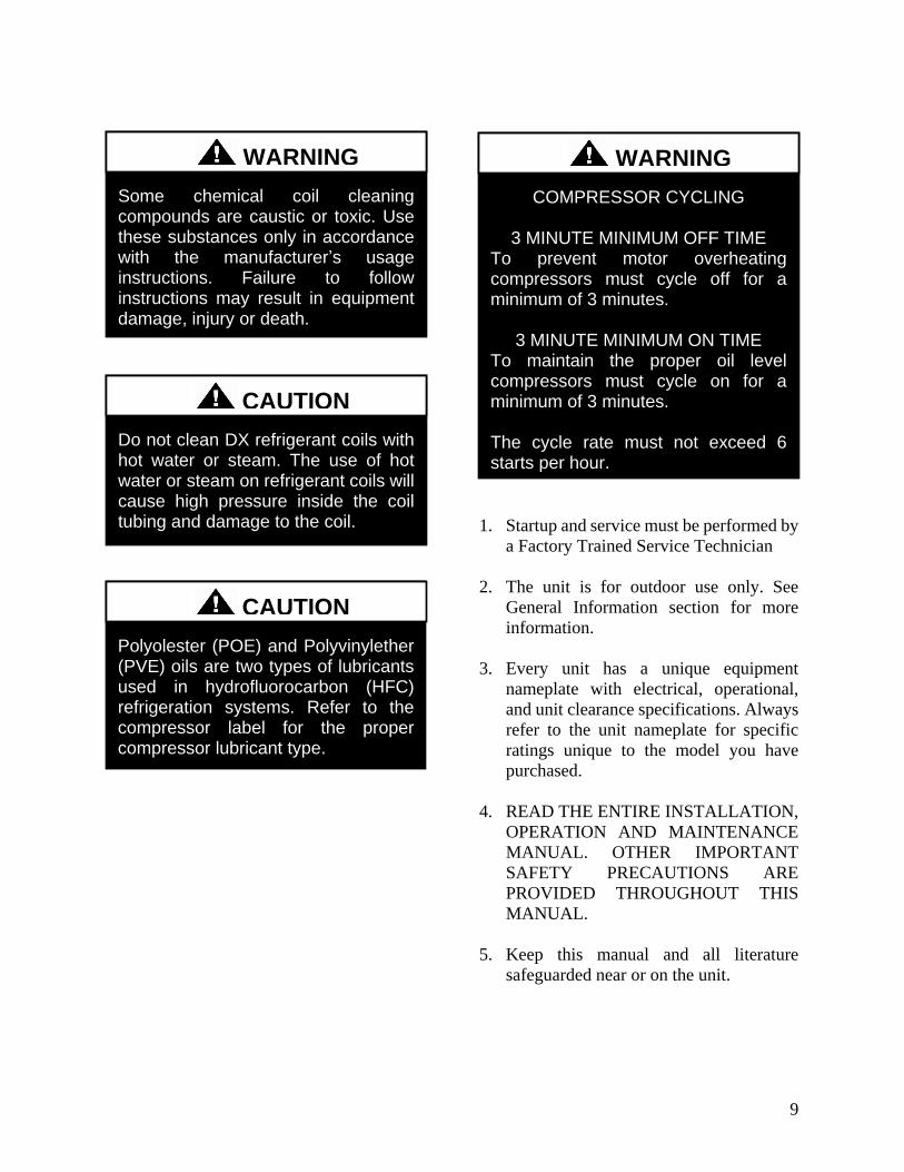
9
1 Startup and service must be performed by
a Factory Trained Service Technician
2 The unit is for outdoor use only See
General Information section for more
information
3 Every unit has a unique equipment
nameplate with electrical operational
and unit clearance specifications Always
refer to the unit nameplate for specific
ratings unique to the model you have
purchased
4 READ THE ENTIRE INSTALLATION
OPERATION AND MAINTENANCE
MANUAL OTHER IMPORTANT
SAFETY PRECAUTIONS ARE
PROVIDED THROUGHOUT THIS
MANUAL
5 Keep this manual and all literature
safeguarded near or on the unit
Some chemical coil cleaning compounds are caustic or toxic Use these substances only in accordance with the manufacturerrsquos usage instructions Failure to follow instructions may result in equipment damage injury or death
WARNING
Do not clean DX refrigerant coils with hot water or steam The use of hot water or steam on refrigerant coils will cause high pressure inside the coil tubing and damage to the coil
CAUTION
Polyolester (POE) and Polyvinylether (PVE) oils are two types of lubricants used in hydrofluorocarbon (HFC) refrigeration systems Refer to the compressor label for the proper compressor lubricant type
CAUTION
COMPRESSOR CYCLING
3 MINUTE MINIMUM OFF TIME To prevent motor overheating compressors must cycle off for a minimum of 3 minutes
3 MINUTE MINIMUM ON TIME To maintain the proper oil level compressors must cycle on for a minimum of 3 minutes The cycle rate must not exceed 6 starts per hour
WARNING
10
LN Series Feature String Nomenclature
Model Options Unit Feature Options
GE
N
MJ
RE
V
SIZ
E
SE
RIE
S
MN
RE
V
VL
T
A1
A2
A3
A4
A5
B1
B2
B3
B4
1
2
3A
3B
3C
3D
4A
4B
4C
4D
5A
5B
5C
5D
6
7
8A
8B
8C
9
10A
10B
10C
10D
LN A ndash 140 ndash C ndash A ndash 3 ndash F A C 0 E ndash 0 0 0 0 A 0 ndash 0 0 0 0 ndash 0 0 0 0 ndash 0 0 0 0 ndash 0 0 ndash 0 0 0 ndash 0 ndash 0 E 0 0 ndash
0 0 0 0 0 ndash 0 A 0 0 0 ndash 0 0 0 0 0 ndash 0 0 0 0 0 0 ndash 0 0 0 0 0 ndash 0 0 0 B
11
12
13
14
15
16
17
18
19
20
21
22
23
24
25
26A
26B
26C
26D
26E
26F
27
28
29
30
31
32
33
34
35
MODEL OPTIONS SERIES AND GENERATION
LN
MAJOR REVISION
A
UNIT SIZE
045 = 45 ton Capacity
055 = 55 ton Capacity
060 = 60 ton Capacity
075 = 75 ton Capacity
095 = 95 ton Capacity
105 = 105 ton Capacity
120 = 120 ton Capacity
140 = 140 ton Capacity
SERIES
A = 45-60 ton units
B = 75 ton unit
C = 95-140 ton units
MINOR REVISION
A
VOLTAGE
2 = 230V3Φ60Hz
3 = 460V3Φ60Hz
4 = 575V3Φ60Hz
8 = 208V3Φ60Hz
A1 COMPRESSOR STYLE
F = R-410A Tandem VFD Compatible Scroll
Compressor
A2 CONDENSER STYLE
A = Air-Cooled Microchannel Condenser
A3 EVAPORATOR CONFIGURATION
A = Standard Brazed Plate Constant Flow
B = Oversized Brazed Plate Constant Flow
C = Standard Shell amp Tube Constant Flow
D = Oversized Shell amp Tube Constant Flow
A4 COATING
0 = Standard
E = Polymer E-Coated Condenser Coil
A5 STAGING
0 = Staged Compressors
E = All Circuits with Variable Capacity Compressors
- 2 Circuits
G = Half Circuits with Variable Capacity
Compressors - 2 Circuits
B1 BLANK
0 = Standard
B2 BLANK
0 = Standard
B3 BLANK
0 = Standard
B4 BLANK
0 = Standard
UNIT FEATURE OPTIONS 1 UNIT ORIENTATION
A = Standard Access Left Water Connections
B = Standard Access Right Water Connections
C = Standard Access Bottom Water Connections
2 PUMPING STYLE
0 = No Pumps
B = Constant Flow Primary Pumping System - Large
Pipe Size
D = Variable Flow Primary Pumping System - Large
Pipe Size
11
LN Series Feature String Nomenclature
Model Options Unit Feature Options
GE
N
MJR
EV
S
IZE
SE
RIE
S
MN
RE
V
VL
T
A1
A2
A3
A4
A5
B1
B2
B3
B4
1
2 3A
3B
3C
3D
4A
4B
4C
4D
5A
5B
5C
5D
6
7
8A
8B
8C
9
10A
10B
10C
10D
LN A ndash 140 ndash C ndash A ndash 3 ndash F A C 0 E ndash 0 0 0 0 A 0 ndash 0 0 0 0 ndash 0 0 0 0 ndash 0 0 0 0 ndash 0 0 ndash 0 0 0 ndash 0 ndash 0 E 0 0 ndash
0 0 0 0 0 ndash 0 A 0 0 0 ndash 0 0 0 0 0 ndash 0 0 0 0 0 0 ndash 0 0 0 0 0 ndash 0 0 0 B
11
12
13
14
15
16
17
18
19
20
21
22
23
24
25
26A
26B
26C
26D
26E
26F
27
28
29
30
31
32
33
34
35
3A BUILDING PUMP CONFIGURATION
0 = No Building Pumps
A = 1 Pump + High Eff Motor
B = 1 Dual Pump + High Eff Motors
D = 1 Pump + VFD + High Eff Motor
E = 1 Dual Pump + 2 VFDs + High Eff Motors
K = 1 Pump + Field Installed VFD + High Eff Motor
L = 1 Dual Pump + 2 Field Installed VFDs + High
Eff Motors
3B BUILDING PUMP SERIES AND RPM
0 = No Building Pumps
A = 4360 (1170 nominal rpm)
B = 4360 (1760 nominal rpm)
C = 4360 (3520 nominal rpm)
D = 4380 (1170 nominal rpm)
E = 4380 (1760 nominal rpm)
F = 4380 (3520 nominal rpm)
K = 4382 (1170 nominal rpm)
L = 4382 (1760 nominal rpm)
M = 4382 (3520 nominal rpm)
3C PUMP SIZE
0 = No Building Pumps
A = 15B
B = 2B
C = 2D
D = 3D
E = 15x15x6
F = 2x2x6
G = 3x3x6
H = 4x4x6
J = 6x6x6
K = 15x15x8
L = 2x2x8
M = 3x3x8
N = 4x4x8
P= 5x5x8
Q = 6x6x8
R = 8x8x8
S = 2x2x10
T = 3x3x10
U = 4x4x10
V = 6x6x10
W = 8x8x10
Y = 4x4x115
Z = 5x5x115
1 = 6x6x115
2 = 8x8x115
3 = 4x4x13
4 = 6x6x13
5 = 8x8x13
12
LN Series Feature String Nomenclature
GE
N
MJR
EV
S
IZE
SE
RIE
S
MN
RE
V
VL
T
A1
A2
A3
A4
A5
B1
B2
B3
B4
1
2
3A
3B
3C
3D
4
A
4B
4C
4D
5A
5B
5C
5D
6
7
8A
8B
8C
9
1
0A
10
B
10
C
10D
LN A ndash 140 ndash C ndash A ndash 3 ndash F A C 0 E ndash 0 0 0 0 A 0 ndash 0 0 0 0 ndash 0 0 0 0 ndash 0 0 0 0 ndash 0 0 ndash 0 0 0 ndash 0 ndash 0 E 0 0 -
0 0 0 0 0 ndash 0 A 0 0 0 ndash 0 0 0 0 0 ndash 0 0 0 0 0 0 ndash 0 0 0 0 0 ndash 0 0 0 B
11
12
13
14
15
16
17
18
19
20
21
22
23
24
25
26A
26B
26C
26D
26E
26F
27
28
29
30
31
32
33
34
35
3D BUILDING PUMP MOTOR SIZE
0 = No Building Pumps
C = 1 hp
E = 2 hp
F = 3 hp
G = 5 hp
H = 75 hp
J = 10 hp
K = 15 hp
L = 20 hp
M = 25 hp
N = 30 hp
P = 40 hp
Q = 50 hp
4A BLANK
0 = Standard
4B BLANK
0 = Standard
4C BLANK
0 = Standard
4D BLANK
0 = Standard
5A BLANK
0 = Standard
5B BLANK
0 = Standard
5C BLANK
0 = Standard
5D BLANK
0 = Standard
6 REFRIGERATION OPTIONS
0 = Standard
A = Hot Gas Bypass on Non-Variable Capacity
Circuits
B = Hot Gas Bypass - All Circuits
7 REFRIGERATION ACCESSORIES
0 = Standard
A = Sight Glass
B = Compressor Isolation Valves
C = Option A + B
8A UNIT DISCONNECT TYPE
0 = Standard Single Point Power Block
A = Single Point Power Non-fused Disconnect
8B DISCONNECT SIZE
0 = Power Block
N = 100 amps
R = 150 amps
U = 225 amps
V = 250 amps
Z = 400 amps
3 = 600 amps
5 = 800 amps
7 = 1200 amps
8C BLANK
0 = Standard
9 ACCESSORIES
0 = Standard
B = Phase amp Brown Out Protection
10A UNIT CONTROL SEQUENCE
0 = Standard Controls
10B UNIT CONTROL SUPPLIER
E = MCS Controls
10C CONTROL SUPPLIER OPTIONS
0 = Standard
A = Touchscreen Interface
C = Modem
G = Option A + C
Model Options Unit Feature Options
13
LN Series Feature String Nomenclature
Model Options Unit Feature Options
GE
N
MJR
EV
S
IZE
SE
RIE
S
MN
RE
V
VL
T
A1
A2
A3
A4
A5
B1
B2
B3
B4
1
2
3A
3B
3C
3D
4A
4B
4C
4D
5A
5B
5C
5D
6
7
8A
8B
8C
9
10A
10B
10C
10
D
LN A ndash 140 ndash C ndash A ndash 3 ndash F A C 0 E ndash 0 0 0 0 A 0 ndash 0 0 0 0 ndash 0 0 0 0 ndash 0 0 0 0 ndash 0 0 ndash 0 0 0 ndash 0 ndash 0 E 0 0 ndash
0 0 0 0 0 ndash 0 A 0 0 0 ndash 0 0 0 0 0 ndash 0 0 0 0 0 0 ndash 0 0 0 0 0 ndash 0 0 0 B
11
12
13
14
15
16
17
18
19
20
21
22
23
24
25
26
A
26
B
26
C
26D
26E
26F
27
28
29
30
31
32
33
34
35
10D BMS CONNECTION amp DIAGNOSTICS
0 = None
A = BACnet IP
B = BACnet MSTP
C = Modbus IP
D = Modbus RTU
E = Lontalk
H = No BMS Connection with Diagnostics
J = BACnet IP with Diagnostics
K = BACnet MSTP with Diagnostics
L = Modbus IP with Diagnostics
M = Modbus RTU with Diagnostics
N = Lontalk with Diagnostics
11 BLANK
0 = Standard
12 VESTIBULE ACCESSORIES
0 = Standard
C = Vestibule Heating (Electric)
13 MAINTENANCE ACCESSORIES
0 = Standard
A = 115VAC Convenience Outlet Factory Wired
B = 115VAC Convenience Outlet Field Wired
C = Service Lights
F = Options A + C
J = Options B + C
14 BLANK
0 = Standard
15 CODE OPTIONS
0 = Standard ETL USA Listing
A = Chicago Code
B = ETL USA + Canada Listing
16 SHIPPING SPLITS
0 = One Piece Unit
17 AIR-COOLED CHILLER ACCESSORIES
H = Cond Coil Guards + Three Phase Cond Fan
Motor + Fan Cycling- 35degF Low Ambient
J = Cond Coil Guards + VFD Cond Fan Head
Pressure Control - 0degF Low Ambient
18 BLANK
0 = Standard
19 BLANK
0 = Standard
20 BLANK
0 = Standard
21 BLANK
0 = Standard
22 BLANK
0 = Standard
23 BLANK
0 = Standard
24 CHILLER ACCESSORIES 1
0 = Standard
A = Glycol Chiller
C = Thermometers amp Pressure Gauges
G = Option A + C
25 BLANK
0 = Standard
26A BLANK
0 = Standard
26B BLANK
0 = Standard
26C BLANK
0 = Standard
14
LN Series Feature String Nomenclature
Model Options Unit Feature Options
GE
N
MJR
EV
S
IZE
SE
RIE
S
MN
RE
V
VL
T
A1
A2
A3
A4
A5
B1
B2
B3
B4
1
2
3A
3B
3C
3D
4A
4B
4C
4D
5A
5B
5C
5D
6
7
8A
8B
8C
9
10A
10B
10C
10D
LN A ndash 140 ndash C ndash A ndash 3 ndash F A C 0 E ndash 0 0 0 0 A 0 ndash 0 0 0 0 ndash 0 0 0 0 ndash 0 0 0 0 ndash 0 0 ndash 0 0 0 ndash 0 ndash 0 E 0 0 ndash
0 0 0 0 0 ndash 0 A 0 0 0 ndash 0 0 0 0 0 ndash 0 0 0 0 0 0 ndash 0 0 0 0 0 ndash 0 0 0 B
11
12
13
14
15
16
17
18
19
20
21
22
23
24
25
26A
26B
26C
26
D
26
E
26
F
27
28
29
30
31
3
2
33
34
35
26D BLANK
0 = Standard
26E BLANK
0 = Standard
26F BLANK
0 = Standard
27 BLANK
0 = Standard
28 BLANK
0 = Standard
29 BLANK
0 = Standard
30 BLANK
0 = Standard
31 BLANK
0 = Standard
32 BLANK
0 = Standard
33 WARRANTY
0 = Standard Warranty
D = Compressor Warranty Years 2-5
34 CABINET MATERIAL
0 = Standard - Double Wall + R-13 Foam Insulation
35 PAINT amp SPECIAL PRICING
AUTHORIZATIONS
B = Premium AAON Gray Paint Exterior
E = Premium AAON Gray Paint Exterior + Shrink
Wrap
X = Special Pricing Authorization + Premium AAON
Gray Paint Exterior
1 = SPA + Premium AAON Gray Paint Exterior +
Shrink Wrap
4 = Special Pricing Authorization + Special Exterior
Paint Color
7 = SPA + Special Exterior Paint Color + Shrink
Wrap
15
General Information
AAON LN Series chillers are complete self-
contained liquid chilling units They are
assembled wired charged and run-tested
Models are available for air-cooled
applications Chiller primary pumping
packages are available as optional features
Codes and Ordinances
LN Series units have been tested and
certified by ETL in accordance with UL
Safety Standard 1995CSA C222 No 236
System should be sized in accordance with
the American Society of Heating
Refrigeration and Air Conditioning
Engineers Handbook
Installation of LN Series units must conform
to the ICC standards of the International
Mechanical Code the International Building
Code and local building plumbing and
waste water codes All appliances must be
electrically grounded in accordance with
local codes or in the absence of local codes
the current National Electric Code
ANSINFPA 70 or the current Canadian
Electrical Code CSA C221
Receiving Unit
When received the unit should be checked
for damage that might have occurred in
transit If damage is found it should be noted
on the carrierrsquos Freight Bill A request for
inspection by carrierrsquos agent should be made
in writing at once Nameplate should be
checked to ensure the correct model sizes and
voltages have been received to match the job
requirements
If repairs must be made to damaged goods
then the factory should be notified before any
repair action is taken in order to protect the
warranty Certain equipment alteration
repair and manipulation of equipment
without the manufacturerrsquos consent may void
the product warranty Contact AAON
Technical Support for assistance with
Improper installation adjustment alteration service or maintenance can cause property damage personal injury or loss of life Startup and service must be performed by a Factory Trained Service Technician
WARNING
The Clean Air Act of 1990 bans the intentional venting of refrigerant as of July 1 1992 Approved methods of recovery recycling or reclaiming must be followed
CAUTION
Coils and sheet metal surfaces present sharp edges and care must be taken when working with equipment
Failure to observe the following instructions will result in premature failure of your system and possible voiding of the warranty
WARNING
WARNING
16
handling damaged goods repairs and freight
claims (918) 382-6450
Storage
If installation will not occur immediately
following delivery store equipment in a dry
protected area away from construction traffic
and in the proper orientation as marked on the
packaging with all internal packaging in
place Secure all loose-shipped items
Chiller
Failure to observe the following instructions
will result in premature failure of your
system and possible voiding of the warranty
Never turn off the main power supply to the
unit except for complete shutdown When
power is cut off from the unit any
compressors using crankcase heaters cannot
prevent refrigerant migration This means the
compressor will cool down and liquid
refrigerant may accumulate in the
compressor The compressor is designed to
pump refrigerant gas and damage may occur
when power is restored if liquid enters the
compressor
Before unit operation the main power switch
must be turned on for at least 24 hours for
units with compressor crankcase heaters
This will give the crankcase heater time to
clear any liquid accumulation out of the
compressor before it is required to run
Rotation must be checked on all MOTORS AND COMPRESSORS of three phase units All motors to include and not be limited to pump motors and condenser fan motors should all be checked by a qualified service technician at startup and any wiring alteration should only be made at the unit power connection
CAUTION
Scroll compressors are directional and will be damaged by operation in the wrong direction Low pressure switches on compressors have been disconnected after factory testing Rotation should be checked by a qualified service technician at startup using suction and discharge pressure gauges and any wiring alteration should only be made at the unit power connection
CAUTION
CRANKCASE HEATER OPERATION
Units may be equipped with compressor crankcase heaters which should be energized at least 24 hours prior to cooling operation to clear any liquid refrigerant from the compressors
CAUTION
COMPRESSOR CYCLING
3 MINUTE MINIMUM OFF TIME To prevent motor overheating compressors must cycle off for a minimum of 3 minutes
3 MINUTE MINIMUM ON TIME To maintain the proper oil level compressors must cycle on for a minimum of 3 minutes The cycle rate must not exceed 6 starts per hour
WARNING
17
Never cut off the main power supply to the
unit except for complete shutdown Always
control the system from the building
management system or control panel never
at the main power supply (except for
emergency or for complete shutdown of the
system)
Scroll compressors must be on a minimum of
3 minutes and off for a minimum of 3
minutes The cycle rate must be no more than
6 starts per hour
The chiller is furnished with a pressure
differential switch that is factory installed
between the chilled water supply and return
connections This sensor must not be
bypassed since it provides a signal to the unit
controller that water flow is present in the
heat exchanger and the unit can operate
without the danger of freezing the liquid
Compressor life will be seriously shortened
by reduced lubrication and the pumping of
excessive amounts of liquid oil and liquid
refrigerant
Wiring Diagrams
A complete set of unit specific wiring
diagrams in both ladder and point-to-point
form are laminated in plastic and located
inside the control compartment door
General Maintenance
When the initial startup is made and on a
periodic schedule during operation it is
necessary to perform routine service checks
on the performance of the chiller This
includes reading and recording suction
pressures and checking for normal sub-
cooling and superheat See the air-cooled
condenser sections in this manual for specific
details
Chiller Primary Pumping
Primary pumping uses a single pump to move
water (or glycol) through the chiller barrel
and back to the building This pumping
package provides a constant or variable flow
of water to the system The pump is activated
whenever the chiller is given a run signal
Water enters the unit through the return water
piping and then travels through an air
separator to remove any air that is entrapped
in the water Following this the water flows
through a suction guide with strainer The
end of the suction guide is removable for
strainer access The strainer assembly is
composed of two parts the operational
strainer and the startup strainer (located
inside the operational strainer) which is to be
removed 24 hours after startup
The pump is installed after the suction guide
and before a combination valve (Flo-Trex)
This combination valve acts as isolation
valve check valve and flow balancing valve
The shell and tube or brazed plate evaporator
is placed after the combination valve in the
water circuit with a flow switch installed
across its inlet and outlet This flow switch
closes when the velocity is above 07 feet per
second The closing flow switch signals the
control system to indicate flow through the
heat exchanger and allow cooling to activate
as required to maintain the setpoint The
water exiting the chiller evaporator leaves the
unit through the water out connection
18
Automatic Air Vent
There is an automatic air vent installed at the
high point of the system inside the pumping
package compartment The air vent valve
must be in the proper position for operation
Ensure that the small vent cap is loosened two
turns from the closed position allowing air to
be vented from the system It is advisable to
leave the cap on to prevent impurities from
entering the valve See appendix for
additional information
Dual Pumps
When redundant pumping is required factory
installed dual pumps can be ordered A dual
pump is a pump with two independent motors
and pumps in a single casing This dual pump
has a swing split-flapper valve in the
discharge port to prevent liquid recirculation
when only one pump is operating Isolation
valves in the casing allow one pump to be
isolated and removed for service while the
other pump is still operating
The controls package will activate the pump
when the unit is given a run command If the
controls do not recognize flow in 60 seconds
the second pump will be activated and an
alarm signal will be generated If the second
pump does not activate the cooling will be
locked out See appendix for additional
information
Pressure Gauges and Thermometers
Pressure gauges and thermometers are
available as a factory installed option
Thermometers are installed on the inlet and
outlet of the unit One pressure gauge is
installed at each pump This pressure gauge
is connected in three places to the water
piping before the suction guidestrainer after
the suction guide and before the pump and
after the pump There is also a needle valve
at each of these points to isolate the pressure
To measure the pressure at any given point
open the needle valve at that point and close
the other two needle valves One gauge is
used so that the calibration of the pressure
gauge is irrelevant in the calculation of the
differential pressure
Pipe Insulation
The water piping and components on units
with pumping packages are not insulated at
the factory Insulation should be installed on
the water piping after the system has been
checked for leaks
19
Installation
Chiller Placement
The AAON LN Series is designed for
outdoor applications and mounting at ground
level or on a rooftop It must be placed on a
level and solid foundation that has been
prepared to support its weight
The placement relative to the building air
intakes and other structures must be carefully
selected Be sure to observe the dimensions
that are on the rating plate of the chiller for
operational and service clearances
Table 1 - Service Clearances
Location Unit Size
45-140 tons
Front -
(Controls Side) 72rdquo
Back 72rdquo
Ends 96rdquo
Top Unobstructed
Condenser coils and fans must be free of any
obstructions in order to start and operate
properly with a correct amount of airflow
For proper unit operation the immediate area
around condenser must remain free of debris
that may be drawn in and obstruct airflow in
the condensing section
Consideration must be given to obstruction
caused by snow accumulation when placing
the unit
Curb and Steel Mount Installation
Make openings in the roof decking large
enough to allow for water piping electrical
penetrations and workspace only Do not
make openings larger than necessary Set the
curb to coincide with the openings Make
sure curb is level
If the LN is installed on a curb use a curb cap
for the open area under the condenser section
Unit specific curb drawing is included with
job submittal See SMACNA Architectural
Sheet Metal Manual for curb installation
details
Units require rail support along all four sides
of the unit base
When installed at ground level a one-piece
concrete slab should be used with footings
that extend below the frost line Care must
also be taken to protect the coil and fins from
damage due to vandalism or other causes
If unit is elevated a field supplied catwalk is
recommended to allow access to unit service
doors
This unit ships with a curb gasket that is 1frac14rdquo
wide and 1frac12rdquo tall It is recommended that this
or another similar gasket be used between the
curb and the unit to reduce vibration from the
unit to the building
All roofing work should be performed by competent roofing contractors to avoid any possible leakage
CAUTION
Figure 1 - LN Base
20
Figure 2 - Curb Mounting with Dimensions
Figure 3 - Steel Mounting Rail with
Dimensions
Table 2 - Mounting Dimensions
Tons A B C D
45-140 142rdquo 138rdquo 134rdquo 139rdquo
Figure 2
Figure 3
Lifting and Handling
If cables or chains are used to hoist the unit
they must be the same length and care should
be taken to prevent damage to the cabinet
See Figure 5 and Figure 6 for additional
information
Before lifting unit be sure that all shipping
material has been removed from unit Secure
hooks and cables at all lifting points lugs
provided on the unit
Hoist unit to a point directly above the curb
or mounting rail Be sure that the gasket
material has been applied to the curb or
mounting rail
Carefully lower and align unit with utility and
duct openings Lower the unit until the unit
skirt fits around the curb Make sure the unit
is properly seated on the curb and is level
Figure 4 - Lifting Points
21
Figure 5 - Lifting Detail of a 45-60 ton Unit
Figure 6 - Lifting Detail of a 75-140 ton Unit
Lifting slot locations are unit specific
Unit must be rigged at all marked lifting points
22
Water Connection
Connect the supply and return water lines
The connection size is listed on the unit rating
sheet along with the designed volumetric
flow rate The maximum operating pressure
for AAON LN Series units is 125 psi
Mounting Isolation
For roof mounted applications or anytime
vibration transmission is a factor vibration
isolators may be used
Access Doors
Lockable access door is provided to the
compressor and control compartment A
separate access door is also provided to the
pumping package compartment
A light switch with service lights is provided
on the wall of the compressor and control
compartment
End Flashing Installation
On all LN Series units the cabinet width will
overhang the shipping trailer on each side
In order to secure and protect the unit during
transit the sheet metal end flashings have
been removed from the unit The slot created
at the base of each end of the unit allows the
unit to set firmly on the trailer deck
Sheet metal flashings are shipped loose with
the unit and once the unit is set into place the
flashings must be installed on each end of the
unit to complete the finished seal at the base
The flashings are unit specific and designed
to cover the slot at each end of the unit to
prevent water run-off into the curb
Failure to attach and seal the end of unit with
the flashings may result in water leakage into
the curb
Figure 7 - Factory Supplied End Flashings
PVC (Polyvinyl Chloride) and CPVC (Chlorinated Polyvinyl Chloride) are vulnerable to attack by certain chemicals Polyolester (POE) oils used with R-410A and other refrigerants even in trace amounts in a PVC or CPVC piping system will result in stress cracking of the piping and fittings and complete piping system failure
CAUTION
The chiller must be operated only with liquid flowing through the evaporators
WARNING
Installing Contractor is responsible for proper sealing of the water piping entries into the unit Failure to seal the entries may result in damage to the unit and property
CAUTION
23
Low Ambient Operation
If the chiller is ordered for a Low Ambient
application the liquid system must use a
glycol solution and the piping must be
insulated to be prepared for freezing
conditions Care must be taken in the source
of electrical power for the heating tape and
thermostat
Electrical
The single point electrical power connections
are made in the electrical control
compartment
The microprocessor control furnished with
the unit is supplied with its own power supply
factory wired to the main power of the
outdoor mechanical room
Verify the unit nameplate voltage agrees with
the power supply Connect power and control
field wiring as shown on the unit specific
wiring diagram provided with the unit
Size supply conductors based on the unit
MCA rating Supply conductors must be
rated a minimum of 167degF (75degC)
Route power and control wiring separately
through the utility entry Do not run power
and signal wires in the same conduit
Protect the branch circuit in accordance with
code requirements The unit must be
electrically grounded in accordance with
local codes or in the absence of local codes
the current National Electric Code
ANSINFPA 70 or the current Canadian
Electrical Code CSA C221
Power wiring is to the unit terminal block or
main disconnect All wiring beyond this point
has been done by the manufacturer and
cannot be modified without effecting the
units agencysafety certification
Figure 8 - Front View of Utility Entry and
Power Switch from Control Compartment
Electric shock hazard Before attempting to perform any installation service or maintenance shut off all electrical power to the unit at the disconnect switches Unit may have multiple power supplies Failure to disconnect power could result in dangerous operation serious injury death or property damage
WARNING
In order to prevent water leakage into the roof curb the factory provided sheet metal flashings MUST BE attached to the unit base to cover the shipping slots at both ends of the unit
CAUTION
24
Startup technician must check for proper
motor rotation and check fan motor amperage
listed on the motor nameplate is not
exceeded Motor overload protection may be
a function of the variable frequency drive and
must not be bypassed
Note All units are factory wired for
208230V 460V or 575V If unit is to be
connected to a 208V supply the transformer
must be rewired to 208V service For 208V
service interchange the yellow and red
conductor on the low voltage control
transformer
Red-Black for 208V
Yellow-Black for 230V
Wire control signals to the unitrsquos low voltage
terminal block located in the controls
compartment All wiring beyond this point
has been completed by the manufacturer and
cannot be modified without effecting the
unitrsquos agencysafety certification
If any factory installed wiring must be
replaced use a minimum 221degF (105degC) type
AWM insulated conductors
Supply voltage must be within the minmax
range shown on the unit nameplate Available
short circuit current should not exceed the
short circuit current rating (SCCR) shown on
the unit nameplate
Three phase voltage imbalance will cause
motor overheating and premature failure
The maximum allowable imbalance is 5
Voltage imbalance is defined as 100 times the
maximum deviation from the average voltage
divided by the average voltage
Example
(218V+237V+235V)3 = 230V then
100(230V-218V)230V = 52 which
exceeds the allowable imbalance
Check voltage imbalance at the unit
disconnect switch and at the compressor
terminal Contact your local power company
for line voltage corrections
Three phase voltage imbalance will cause motor overheating and premature failure
CAUTION
Scroll compressors are directional and will be damaged by operation in the wrong direction Low pressure switches on compressors have been disconnected after factory testing Rotation should be checked by a qualified service technician at startup using suction and discharge pressure gauges and any wiring alteration should only be made at the unit power connection
Installing Contractor is responsible for proper sealing of the electrical and gas entries into the unit Failure to seal the entries may result in damage to the unit and property
CAUTION CAUTION
25
Variable Speed Compressors
Variable speed compressors should not be
operated outside the factory determined
frequency range The factory determined
compressor VFD frequency range is given
below in Table 3
Table 3- Tandem Circuited Variable Speed
Compressor VFD Frequency Range
Model (LN-) Compressor VFD
Range (Hz)
208V 230V 460V and 575V Units
045 055 060 45-65Hz
075 45-70Hz
095 105 120 35-60 Hz
140 35-65 Hz
No variable speed compressor shall operate below 35 Hz Operating variable speed compressors outside the frequency range specified in this manual voids all warranties and may result in compressor failure
CAUTION
Rotation must be checked on all MOTORS AND COMPRESSORS of three phase units Condenser fan motors should all be checked by a qualified service technician at startup and any wiring alteration should only be made at the unit power connection Variable frequency drives are programmed to automatically rotate the fan in the correct rotation Do not rely on fans with variable frequency drives for compressor rotation
CAUTION
26
Startup (See back of the manual for startup form)
Before the startup of the chiller be sure that
the following items have been checked
1 Verify that electrical power is available to
the unit
2 Verify that any remote stopstart device
connected to the chiller controller is
requesting the chiller to start
3 Verify that liquid flow is present through
the chiller from the building
4 There should be a building load of at least
25 of the chiller capacity in order to
properly check operation
5 With the main power switch off review
the MCS Controller Manual provided
with the chiller Understand the keypad
functions how to set the leaving water
temperature setpoint and how to initiate
the Run State
Use the general check list at the top of the
startup form to make a last check that all the
components are in place water flow is
present and the power supply is energized
Using the controller keypad individually set
the outputs in ldquoManual Onrdquo to confirm relay
closure and compressor operation
Cycle through all the compressors to confirm
that all are operating within tolerance
While performing the check use the startup
form to record observations of compressor
amps and refrigerant pressures
When all is running properly place the
controller in the Run mode and observe the
system until it reaches a steady state of
operation
Note For more information on programming
the controller refer to the MCS Controller
manual provided with the chiller
Electric shock hazard Shut off all electrical power to the unit to avoid shock hazard or injury from rotating parts
WARNING
Improper installation adjustment alteration service or maintenance can cause property damage personal injury or loss of life Startup and service must be performed by a Factory Trained Service Technician
WARNING
Rotation must be checked on all MOTORS AND COMPRESSORS of three phase units All motors to include and not be limited to pump motors and condenser fan motors should all be checked by a qualified service technician at startup and any wiring alteration should only be made at the unit power connection
CAUTION
Before completing installation a complete operating cycle should be observed to verify that all components are functioning properly
CAUTION
27
Axial Flow Condenser Fans
Multi-Wing Z Series Aluminum Fan Blade
Pitch Angle Setting Instructions
1 Maintain the balance of fan
Mark the hub castings across a joint so the
fan hub can be reassembled in the same
orientation
Mark the location of any balancing weight
Balancing weight will be on the outer bolt
circle in the form of washers andor longer
bolts or an additional balancing nut
Number the blades and blade sockets so that
they are replaced into their original position
Figure 9 - Fan with the HUB on the top and
RET on the bottom
2 Determine the direction of rotation
Right R is clockwise when facing the
discharge side of the fan and Left L is
counterclockwise when facing the discharge
side of the fan
3 Determine the bushing mount location
The bushing mount is the center section of the
hub through which the fan is mounted to the
shaft and typically contains either setscrews
or a center-tapered hole where the bushing
inserts
Location A is with the bushing mount on air
inlet side of the fan
Location B is with the bushing mount on air
discharge side of the fan
Figure 10 - Bushing Mount Location
4 Determine the pin location groove
Disassemble fan on a flat surface and note in
which groove the pin is located
Figure 11 - RET with Pin in Groove 4
Bushing
Mount
A B Bushing
Mount
Bushing Bushing
1 2 3 4
28
5 Determine whether the pin is in the HUB
or RET
Figure 12 - Fan HUB and RET Castings
6 Determine the current blade pitch and the pin location for the new blades
Table 4 - ReturnExhaust Fan Pin Location
Type Bushing
Mount
Blade Pitch Angle
20deg 25deg 28deg 30deg 33deg 35deg 38deg 40deg 45deg 50deg
5Z A - RET - RET RET RET HUB HUB HUB HUB
B - HUB - HUB HUB HUB RET RET RET RET
Table 5 - ReturnExhaust Fan Pin Location
Type Rot Blade Pitch Angle
20deg 25deg 28deg 30deg 33deg 35deg 38deg 40deg 45deg 50deg
5Z R - 4 - 3 2 1 4 3 2 1
L - 1 - 2 3 4 1 2 3 4
7 Replace fan blades in the new pin
location and reassemble the fan
Replace the blades with the pin in the 1 2 3
or 4 groove position of either the HUB or
RET Assemble the fan making sure to place
the blades in their previous blade sockets to
match up the previous orientation of HUB
and RET and to replace any balancing
weights in their previous locations Tighten
bolts in a cross pattern to 5-6 ft-lbs of torque
29
Multi-Wing W Series Black Glass
Reinforced Polypropylene Fan Blade Pitch
Angle Setting Instructions
Contact the AAON parts department to
acquire the new pitch pins for the fan blades
Note original position of retaining plates
center boss and all hardware including
additional hardware used for balancing
1 Remove all the bolts and nuts
2 Determine blade rotation ndash on the concave
side of the blade is a blade marking showing
6WR 6WL 7WL 7WR or 9WR The ldquoLrdquo
and ldquoRrdquo denote the rotation of the blade
3 Replace the pitch insert in the blade root
with an insert of the desired pitch
Figure 13 - Pitch Insert
4 Replace blades to their original location
5 Replace all nuts bolts and washers on the
fan hub
6 Replace retaining plates and center boss to
original location
7 Tighten nuts and bolts to 14 ft-lbs of
torque
Fan Assembly Bushings
The fan assembly bushings should be
tightened to the specifications listed in the
following table
Table 6 - Fan Assembly Bushing Torque
Specifications
Bushing Tightening Torque
(in-lbs)
H X 1125 95
H X 1375 95
SH X 1125 108
SH X 1375 108
SD X 1125 108
SD X 1375 108
SD X 1625 108
SD X 1875 108
SK X 2125 180
30
Maintenance
General
Qualified technicians must perform routine
service checks and maintenance This
includes reading and recording the
condensing and suction pressures and
checking for normal sub-cooling and
superheat
Air-cooled chillers require maintenance
schedulesprocedures Unit specific
instructions are included in this manual
Compressors
The scroll compressors are fully hermetic and
require no maintenance except keeping the
shell clean
Refrigerant Suction Line Filter
Each refrigerant circuit contains a
replaceable core suction line filter One
month after start-up remove the filter
element
The replaceable core suction filters are
provided with pressure taps and shutoff
valves for isolation when removing the filter
For safety purposes a service manifold must
be attached prior to filter maintenance
Suction Filter Removal Instructions
1 Shut down operation of the unit
2 Close both shut-off valves to isolate
the suction filter
3 Reclaim the refrigerant from the
suction filter section
4 Remove the bolts from the suction
filter end plate
5 Remove the pleated filter assembly
Prior to filter core service a service manifold MUST BE attached to in and out pressure connections to assure no pressure exists during filter maintenance Non-compliance could result in injury or violation of EPA regulations
Service gauges MUST BE connected before operating the isolation valves for the replaceable core filter
WARNING
WARNING
31
6 Replace the suction filter end plate
and bolts
7 Evacuate the suction filter assembly
to 500 microns
8 Open both shut-off valves
Adjusting Refrigerant Charge
All AAON chillers are shipped with a full
factory charge Periodically adjusting the
charge of a system may be required
Adjusting the charge of a system in the field
must be based on determination of liquid sub-
cooling and evaporator superheat On a
system with an expansion valve liquid sub-
cooling is more representative of the charge
than evaporator superheat but both
measurements must be taken
Before Charging
Refer to the unit nameplate as a reference
when determining the proper refrigerant
charge
Unit being charged must be at or near full
load conditions before adjusting the charge
Units equipped with hot gas bypass must
have the hot gas bypass valve closed to get
the proper charge
After adding or removing charge the system
must be allowed to stabilize typically 10-15
minutes before making any other
adjustments
The type of unit and options determine the
ranges for liquid sub-cooling and evaporator
superheat Refer to Table 7 when determining
the proper sub-cooling
For units equipped with low ambient (0degF)
option see the special charging instructions at
the end of this section
Checking Liquid Sub-cooling
Measure the temperature of the liquid line as
it leaves the condenser coil
Read the gauge pressure at the liquid line
close to the point where the temperature was
taken You must use liquid line pressure as it
will vary from discharge pressure due to
condenser coil pressure drop
Convert the pressure obtained to a saturated
temperature using the appropriate refrigerant
temperature-pressure chart
Subtract the measured liquid line temperature
from the saturated temperature to determine
the liquid sub-cooling
Compare calculated sub-cooling to the table
below for the appropriate unit type and
options
The Clean Air Act of 1990 bans the intentional venting of refrigerant (CFCrsquos and HCFCrsquos) as of July 1 1992 Approved methods of recovery recycling or reclaiming must be followed Fines andor incarceration may be levied for non-compliance
CAUTION
Polyolester (POE) and Polyvinylether (PVE) oils are two types of lubricants used in hydrofluorocarbon (HFC) refrigeration systems Refer to the compressor label for the proper compressor lubricant type
CAUTION
32
Checking Evaporator Superheat
Measure the temperature of the suction line
close to the compressor
Read gauge pressure at the suction line close
to the compressor
Convert the pressure obtained to a saturated
temperature using the appropriate refrigerant
temperature-pressure chart
Subtract the saturated temperature from the
measured suction line temperature to
determine the evaporator superheat
For refrigeration systems with tandem scroll
compressors it is critical that the suction
superheat setpoint on the expansion valve is
set with one compressor running The suction
superheat should be 10-13degF with one
compressor running The suction superheat
will increase with both compressors in a
tandem running Inadequate suction
superheat can allow liquid refrigerant to
return to the compressors which will wash the
oil out of the compressor Lack of oil
lubrication will destroy a compressor Liquid
sub-cooling should be measured with both
compressors in a refrigeration system
running
Compare calculated superheat to Table 7 for
the appropriate unit type and options
Table 7 - Acceptable Refrigeration Circuit
Values
Air-Cooled Chiller with Scroll
Compressors
Sub-Cooling2 12-18degF
Superheat1 10-15degF 1 One compressor running in tandem 2 Two compressors running in tandem
Adjusting Sub-cooling and Superheat
Temperatures
The system is overcharged if the sub-cooling
temperature is too high and the evaporator is
fully loaded (low loads on the evaporator
result in increased sub-cooling) and the
evaporator superheat is within the
temperature range as shown in Table 7 (high
superheat results in increased sub-cooling)
Correct an overcharged system by reducing
the amount of refrigerant in the system to
lower the sub-cooling
The system is undercharged if the superheat
is too high and the sub-cooling is too low
Correct an undercharged system by adding
refrigerant to the system to reduce superheat
and raise sub-cooling
If the sub-cooling is correct and the superheat
is too high the expansion valve may need
adjustment to correct the superheat
Expansion valves must be adjusted to approximately 10-15degF of suction superheat Failure to have sufficient superheat will damage the compressor and void the warranty
CAUTION
DO NOT OVERCHARGE Refrigerant overcharging leads to excess refrigerant in the condenser coils resulting in elevated compressor discharge pressure
CAUTION
33
Table 8 - R-410A Refrigerant Temperature-Pressure Chart
F psig F psig F psig F psig F psig
20 783 50 1422 80 2349 110 3641 140 5401
21 800 51 1448 81 2386 111 3691 141 5470
22 818 52 1474 82 2423 112 3742 142 5539
23 836 53 1501 83 2460 113 3794 143 5609
24 854 54 1528 84 2498 114 3846 144 5679
25 872 55 1555 85 2537 115 3899 145 5751
26 891 56 1582 86 2575 116 3952 146 5823
27 910 57 1610 87 2614 117 4005 147 5896
28 929 58 1638 88 2654 118 4059 148 5969
29 949 59 1667 89 2694 119 4114 149 6044
30 968 60 1696 90 2735 120 4169 150 6119
31 988 61 1725 91 2776 121 4225
32 1009 62 1754 92 2817 122 4282
33 1029 63 1784 93 2859 123 4339
34 1050 64 1815 94 2901 124 4396
35 1071 65 1845 95 2944 125 4454
36 1092 66 1876 96 2987 126 4513
37 1114 67 1907 97 3030 127 4573
38 1136 68 1939 98 3075 128 4632
39 1158 69 1971 99 3119 129 4693
40 1181 70 2004 100 3164 130 4754
41 1203 71 2036 101 3210 131 4816
42 1227 72 2070 102 3256 132 4878
43 1250 73 2103 103 3302 133 4941
44 1274 74 2137 104 3349 134 5005
45 1298 75 2171 105 3396 135 5069
46 1322 76 2206 106 3444 136 5134
47 1347 77 2241 107 3493 137 5200
48 1372 78 2277 108 3542 138 5266
49 1397 79 2313 109 3591 139 5333
34
Lubrication
All original motors and bearings are
furnished with an original factory charge of
lubrication Certain applications require
bearings be re-lubricated periodically The
schedule will vary depending on operating
duty temperature variations or severe
atmospheric conditions
Bearings should be re-lubricated at normal
operating temperatures but not when
running
Rotate the fan shaft by hand and add only
enough grease to purge the seals DO NOT
OVERLUBRICATE
Air-Cooled Condenser
The air-cooled condenser section rejects heat
by passing outdoor air over the fin tube coils
for cooling of the hot refrigerant gas from the
compressors The heated air will discharge
from the top of the section through the axial
flow fans
The condenser coils should be inspected
yearly to ensure unrestricted airflow If the
installation has a large amount of airborne
dust or other material the condenser coils
should be cleaned according to the
microchannel coil cleaning section
Brazed Plate Heat Exchanger Cleaning
Because of a normally high degree of
turbulence in brazed plate heat exchangers
for many applications the heat exchanger
channels are self-cleaning For applications
that are not self-cleaning (ie hard water at
high temperatures etc) or applications where
additional cleaning is desired it is possible to
clean the brazed plate heat exchanger by
circulating a cleaning liquid
Use a tank with weak acid 5 phosphoric
acid (H3PO4) or if the exchanger is
frequently cleaned 5 oxalic acid (H2C2O4)
Pump the cleaning liquid through the
exchanger For optimum cleaning the
cleaning solution flow rate should be a
minimum of 15 times the normal flow rate
preferably in a back-flush mode After
cleaning the heat exchanger must be rinsed
with clean water A solution of 1-2 sodium
hydroxide (NaOH) or sodium bicarbonate
(NaHCO) before the last rinse ensures that all
acid is neutralized
E-Coated Coil Cleaning
Documented quarterly cleaning of e-coated
coils is required to maintain coating warranty
coverage
Surface loaded fibers or dirt should be
removed prior to water rinse to prevent
restriction of airflow If unable to back wash
the side of the coil opposite of the coils
entering air side then surface loaded fibers or
dirt should be removed with a vacuum
cleaner If a vacuum cleaner is not available
a soft non-metallic bristle brush may be used
In either case the tool should be applied in
the direction of the fins Coil surfaces can be
easily damaged (fin edges bent over) if the
tool is applied across the fins
Use of a water stream such as a garden hose
against a surface loaded coil will drive the
fibers dirt and salts into the coil This will
make cleaning efforts more difficult Surface
loaded fibers must be completely removed
prior to using low velocity clean water rinse
Electric shock hazard Shut off all electrical power to the unit to avoid shock hazard or injury from rotating parts
WARNING
35
Quarterly cleaning is required to maintain
warranty coverage and is essential to
maintain the life of an E-coated coil Coil
cleaning shall be part of the units regularly
scheduled maintenance procedures
Failure to clean an E-coated coil on the
prescribed quarterly cycle will void the
warranty and may result in reduced
efficiency and durability in the environment
A routine two-step quarterly coil cleaning is
required to maintain warranty
Step one is to clean the coil with the below
approved coil cleaner (see approved products
list under the Recommended Coil Cleanersrdquo
section
Step two is to use the approved saltchloride
remover under the Recommended Chloride
Removerrdquo section to dissolve soluble salts
and revitalize the unit It is very important
when cleaning andor rinsing not to exceed
130degF and potable water pressure is less than
100 psig to avoid damaging the unit and coil
fin edges
For routine quarterly cleaning first clean the
coil with the below approved coil
cleaner After cleaning the coils with the
approved cleaning agent use the approved
chloride remover to remove soluble salts and
revitalize the unit
Recommended Coil Cleaner ndash Step 1
GulfCoatTM Coil Cleaner assuming it is
used in accordance with the manufacturers
directions on the container for proper mixing
and cleaning has been approved for use on
E-coated coils to remove mold mildew dust
soot greasy residue lint and other
particulate Never use any cleaners that are
not approved
Recommended Chloride Remover ndash Step 2
CHLORRIDreg Concentrate assuming it
is used in accordance with the manufacturers
directions on the container for proper mixing
has been approved for use on E-coated coils
to remove chloridessalts amp sulfates Never
use any chloride removers that are not
approved
Warranty Protection ndash Step 1
Complete the coil cleaning following these
steps
1 Ensure that the power to the unit is off
and locked out
2 Clean the area around the unit if
needed to ensure leaves grass or
High velocity water from a pressure washer or compressed air should only be used at a very low pressure to prevent fin andor coil damages The force of the water or air jet may bend the fin edges and increase airside pressure drop Reduced unit performance or nuisance unit shutdowns may occur
Harsh chemicals household bleach or acid cleaners should not be used to clean e-coated coils These cleaners can be very difficult to rinse out of the coil and can accelerate corrosion and attack the e-coating If there is dirt below the surface of the coil use the recommended coil cleaners
CAUTION
CAUTION
36
loose debris will not be blown into the
coil
3 Remove panels or tops as required
gaining access to the coil(s) to be
cleaned
4 Using a pump up sprayer fill to the
appropriate level with potable water
and add the correct amount of
approved cleaner as per manufacture
instructions leaving room for the
pump plunger to be reinserted
NOTE Coils should always be cleaned
back flushed opposite of airflow to prevent
impacting the dirt into the coil
5 If the coils have heavy dirt fibers
grass leaves etc on the interior or
exterior face areas a vacuum and
brush should be used to remove those
surface contaminants prior to
applying cleaner The interior floor
drain tray or pan areas should also be
vacuumed
6 Apply the mixed cleaner to coil
surfaces using a pressurized pump up
sprayer maintaining a good rate of
pressure and at a medium size nozzle
spray (not a solid stream and not a
wide fan but somewhere in the
middle) Work in sectionspanels
ensuring that all areas are covered and
kept wetted
7 Apply the cleaner to unit interior air
exiting side coil surfaces first Work
in sectionspanels moving side to side
and from top to bottom
8 Generously soak coils by spraying
cleaner directly on and into the fin
pack section to be cleaned and allow
the cleaning solution to soak for 5 to
10 minutes
9 Using pressurized potable water
(lt100 psi) rinse the coils and
continue to always work in
sectionspanels Start at the top of the
coil and slowly move vertically
downward to the bottom Then
staying in the same vertical area
slowly move back up to the top where
you started Now move over slightly
overlapping the area just completed
and repeat above Continue until all
coil areas on the inside of the unit
have been rinsed
10 Complete steps 5-9 for the exterior air
entering side of the coils
11 Final rinse ndash Now complete a quick
rinse of both sides of the coil
including the headers piping u-
bends and hairpins
12 If the coil has a drain pan or unit floor
that is holding rinse water or cleaner
extra time and attention will need to
be taken in those areas to ensure a
proper rinse has been completed
Warranty Protection ndash Step 2
Complete the coil chloride (salt) removal
following these steps
1 CHLORRIDreg is a concentrate to be
used for both normal inland
applications at a 1001 mix ratio OR
for severe coastal applications 501
mix ratio with potable water (256
ounces of Chlorrid to 1 gal of water)
Using a pump up sprayer fill to the
appropriate level with potable water
and add the correct amount of
CHLORRIDreg salt remover leaving
room for the pump plunger to be
reinserted
2 Apply CHLORRIDreg to all external
coil surfaces using a pressurized
pump up sprayer maintaining a good
rate of pressure and at a medium size
nozzle spray (not a solid stream and
not a wide fan but somewhere in the
middle) Work in sectionspanels
ensuring that all areas are covered and
kept wetted
37
3 Generously soak coils by spraying
CHLORRIDreg directly on and into
the fin pack section Let stand for 5 to
10 minutes keeping the area wetted
Do not allow to dry before rinsing
4 Using pressurized potable water
(lt100 psi) rinse the CHLORRIDreg
and dissolved chloridessalts off of
the coils continuing to always work in
sectionspanels
5 Starting at the top of the coil begin
rinsing the coil from side to side until
you reach the bottom Repeat as many
times as is necessary to ensure all coil
sectionspanels have been completed
and are thoroughly rinsed
6 Reinstall all panels and tops that were
removed
Microchannel Coil Cleaning
Documented routine cleaning of
microchannel coils with factory provided e-
coating is required to maintain coating
warranty coverage See E-Coated Coil
Cleaning section
Air-cooled heat exchangers may include
microchannel coils
Cleaning microchannel coils is necessary in
all locations In some locations it may be
necessary to clean the coils more or less often
than recommended In general a condenser
coil should be cleaned at a minimum of once
a year In locations where there is commonly
debris or a condition that causes dirtgrease
build up it may be necessary to clean the coils
more often Proper procedure should be
followed at every cleaning interval Using
improper cleaning technique or incorrect
chemicals will result in coil damage system
performance fall off and potentially leaks
requiring coil replacement
Documented routine cleaning of
microchannel coils with factory provided e-
coating is required to maintain coating
warranty coverage Use the E-Coated Coil
Cleaning section for details on cleaning e-
coated coils
Field applied coil coatings are not
recommended with microchannel coils
Allowed Chemical Cleaners and Procedures
AAON recommends certain chemicals that
can be used to remove buildup of grime and
debris on the surface of microchannel coils
These chemicals have been tested for
performance and safety and are the only
chemicals that AAON will warrant as correct
for cleaning microchannel coils
There are three procedures that are outlined
below that will clean the coils effectively
without damage to the coils Use of any other
procedure or chemical may void the warranty
to the unit where the coil is installed With
all procedures make sure the unit is off
before starting
The water pressure used to clean should not
exceed 140 psi from no closer than 6 inches
from the coils and with the water aimed
perpendicular to the coils
Electric shock hazard Shut off all electrical power to the unit to avoid shock hazard or injury from rotating parts
WARNING
WARNING
38
1 Simple Green
Simple Green is available from AAON Parts
and Supply (Part T10701) and is
biodegradable with a neutral 65 pH
Recommendation is to use it at a 4 to 1 mix
Use the following procedure
1 Rinse the coil completely with water Use
a hard spray but be careful not to bend or
damage the fins A spray that is too hard
will bend the fins Spray from the fan side
of the coil
2 With a pump sprayer filled with a mix of
4 parts water to one part Simple Green
spray the air inlet face of the coil Be sure
to cover all areas of the face of the coil
3 Allow the coil to soak for 10-15 minutes
4 Rinse the coil with water as in step one
5 Repeat as necessary
2 Vinegar
This is standard white vinegar available in
gallons from most grocery stores It has a pH
of 2-3 so it is slightly acidic Use the
following procedure
1 Rinse the coil completely with water Use
a hard spray but be careful not to bend or
damage the fins A spray that is too hard
will bend the fins Spray from the fan side
of the coil
2 Use a pump sprayer filled with vinegar
(100) Spray from the face of the coil in
the same direction as the airflow Be sure
to cover all areas of the face of the coil
3 Allow the coil to soak for 10-15 minutes
4 Rinse the coil with water as in step one
5 Repeat as necessary
3 Water Flush
This procedure can be used when the only
material to cause the coil to need cleaning is
debris from plant material that has impinged
the coil face
1 Rinse the coil completely with water Use
a hard spray but be careful not to bend or
damage the fins A spray that is too hard
will bend the fins Spray from the fan side
of the coil
2 Spray and rinse the coil from the face
Application Examples
The three procedures can be used to clean
microchannel coils They will fit with the
application depending on the area In some
areas where the springsummer has a large
cottonwood bloom 3 might work fine if the
unit is installed on an office building and no
other environmental factors apply
When a unit is installed where the sprinkler
system has water being sprayed onto the
condenser coil you might have better results
using 2 Vinegar is slightly acidic and may
help with the calcium build up from drying
water This also works well when grease is
part of the inlet air to a condenser coil
Generally the best and broadest based
procedure is 1 The grease cutting effect of
the Simple Green is good for restaurant
applications
Other Coil Cleaners
There are many cleaners on the market for
condenser coils Before using any cleaner
that is not covered in this section you must
get written approval from the AAON
warranty and service department Use of
unapproved chemicals will void the
warranty
Use pressurized clean water with pressure not to exceed 140 psi Nozzle should be 6rdquo and 80deg to 90deg from coil face Failure to do so could result in coil damage
CAUTION
39
AAON testing has determined that unless a
chemical has a neutral pH (6-8) it should not
be used
Beware of any product that claims to be a
foaming cleaner The foam that is generated
is caused by a chemical reaction to the
aluminum fin material on tube and fin coils
and with the fin tube and coating material on
microchannel coils
Microchannel coils are robust in many ways
but like any component they must be treated
correctly This includes cleaning the coils
correctly to give optimal performance over
many years
Service
If the unit will not operate correctly and a
service company is required only a company
with service technicians qualified and
experienced in both refrigerant chillers and
air conditioning are permitted to service the
systems to keep warranties in effect If
assistance is required the service technician
must contact AAON
Replacement Parts
Parts for AAON equipment may be obtained
from your local AAON representative When
ordering parts reference the unit serial
number and part number
AAON Technical Support
2424 S Yukon Ave
Tulsa OK 74107
Ph (918) 382-6450
techsupportAAONcom
wwwAAONcom
Note Before calling technician should have
model and serial number of the unit available
for the service department to help answer
questions regarding the unit
40
Appendix - Water Piping Component Information
Automatic Air Vent Valves
Automatic Air Vent Valves provide
automatic air venting for hot or cold water
distribution systems These vents purge air
that may be in the water system
The vent valve utilizes a float to actuate the
valve plug which is located at the top of the
valve Once the air is displaced and the
system pressure is sustained the valve plug
seals and prevents any water from escaping
from the system
The float vent can also operate as an anti-
vacuum device since it will permit air to enter
the system when it must be drained It can
also be installed to permit the separation and
dispersal of air while fluid is actually
circulating in the system
Overview
Body and cover are brass construction
Air vent with silicone rubber seal
Impurities do not usually affect function
as maximum float line of water is always
lower than the valve seal
Float is high temperature resistant
polyethylene
Suitable for use with glycol systems
Can be disassembled for inspection and
cleaning
Operating Range
Minimum working pressure 145psi
(10 kPa)
Maximum working pressure 150psi
(10 bars)
Temperature Range 33degF ndash 240degF
(5degC ndash 116degC)
Performance
Performance curve details the quantity of air
vented by the ldquoFloat Ventrdquo according to the
pressure in the system
Note In order to get the best results in
venting air from risers use connecting pipes
41
of at least 1frasl2 diameter between the ldquoFloat
Ventrdquo valves and installation
Installation
When the air vent valve is installed as shown
the air will not be vented while the fluid is
circulating in the system but it can vent when
the system is shut off
The figure below shows the installation of the
vent valve for the venting of air while the
fluid is circulating in the system and the
required increase in pipe size in order to
obtain proper separation of air from water
The valve should be mounted only in a
vertical position as its operation is based on
the vertical movement of the float
While the air vent valve is in operation back
off the small vent cap two turns This is the
proper operating setting which will allow air
to be vented from the system It is advisable
to leave the cap on to prevent impurities from
entering the valve
Maintenance
No maintenance is normally necessary
However if the FV-4M1 is disassembled for
inspection or cleaning it is important that
when re-assembling to ensure that the spring
loaded lever properly engages under the float
collar
42
Dimensions ndash Weights
Pumps - Installation and Operating
Instructions
Introduction
This document contains specific information
regarding the safe installation operating and
maintenance of Vertical In-Line pumps and
should be read and understood by installing
operating and maintenance personnel The
equipment supplied has been designed and
constructed to be safe and without risk to
health and safety when properly installed
operated and maintained The instructions
following must be strictly adhered to If
clarification is needed on any point please
contact Armstrong quoting the equipment
serial number
Where under normal operating conditions the
limit of 68degC155degF (Restricted Zone) for
normal touch or 80degC176degF (Unrestricted
Zone) for unintentional touch may be
experienced steps should be taken to
minimize contact or warn operatorsusers that
normal operating conditions will be
exceeded In certain cases where the
temperature of the pumped liquid exceeds the
above stated temperature levels pump casing
temperatures may exceed 100degC212degF and
not withstanding pump insulation techniques
appropriate measures must be taken to
minimize risk for operating personnel
Storage
Pumps removed from service and stored
must be properly prepared to prevent
excessive rusting Pump port protection
plates must not be removed until the pump is
ready to connect to the piping Rotate the
shaft periodically (At least monthly) to keep
No Installation of this equipment should take place unless this document has been read and understood
CAUTION
43
rotating element free and bearings fully
functional
For long term storage the pump must be
placed in a vertical position in a dry
environment Internal rusting can be
prevented by removing the plugs at the top
and bottom of the casing and drain or air blow
out all water to prevent rust buildup or the
possibility of freezing Be sure to reinstall the
plugs when the unit is made operational
Rust-proofing or packing the casing with
moisture absorbing material and covering the
flanges is acceptable When returning to
service be sure to remove the drying agent
from the pump
Handling Large VIL Units
One effective way of lifting a large pumping
unit is to place lifting hooks through the
motor lifting rings or straps around the upper
part of the motor The pump and motor unit
will free-stand on the casing ribs Remove the
coupling guard and place (2) lifting straps
through the pumpmotor pedestal one on
each side of the motor shaft and secure to the
lifting device
With the straps in place using a spacer bar if
necessary to protect the motor fan cover the
whole assembly can now be lifted securely
Note Handling transportation and
installation of this equipment should only be
undertaken by trained personnel with proper
use of lifting equipment
Remove coupling guard and place lifting
straps on each side of coupling use spacer
bar if necessary to protect motor fan cover
Vertical Inline Pump Lifting Strap
Positioning
Note All split-coupled pumps contain a
tapped hole in the motor bracket above the
discharge flange for draining the well Pipe
this drain hole to a floor drain to avoid
overflow of the cavity caused by collecting
chilled water condensate or from seal failure
Pump Piping - General
The discharge valve only is to be used to
throttle pump flow not the suction valve
Care must be taken in the suction line layout
and installation as it is usually the major
source of concern in centrifugal pump
applications
Discharge valve only is to be used to throttle pump flow
Use Caution Piping may carry high temperature fluid
CAUTION
CAUTION
44
Alignment
Alignment is unnecessary on close-coupled
pumps as there is no shaft coupling
Split-coupled units are accurately aligned at
the factory prior to being shipped and do not
need re-aligning when installed
Pump Operation
Starting Pump
Ensure that the pump turns freely by hand or
with some mechanical help such as a strap
and lever on larger pumps Ensure that all
protective guarding is securely fixed in
position
The pump must be fully primed on start up
Fill the pump casing with liquid and rotate the
shaft by hand to remove any air trapped in the
impeller On split coupled units any air
trapped in the casing as the system is filled
must be removed by the manual air vent in
the seal flush line Close-coupled units are
fitted with seal flushvent lines piped to the
pump suction area When these units operate
residual air is drawn out of the pump towards
the suction piping
lsquoBumprsquo or energize the motor momentarily
and check that the rotation corresponds with
the directional arrow on the pump casing To
reverse rotation of a three phase motor
interchange any two power leads
Start the pump with the discharge valve
closed and the suction valve open and then
gradually open the discharge valve when the
motor is at operating speed The discharge
valve may be lsquocrackedrsquo or open slightly at
start up to help eliminate trapped air
When stopping the pump Close the
discharge valve and de-energize the motor
DO NOT run the pump against a closed
discharge valve for an extended period of
time (A few minutes maximum)
Star-Delta motor starters should be fitted
with electronicmechanical interlocks that
have a timed period of no more than 40
milliseconds before switching from star
(Starting) to delta (Run) connection yet allow
the motor to reach full star (Starting) speed
before switching to delta (Run)
Should the pump be noisy or vibrate on start-
up a common reason is overstated system
head Check this by calculating the pump
operating head by deducting the suction
pressure gauge value from the discharge
gauge reading Convert the result into the
units of the pump head as stated on the pump
nameplate and compare the values Should
the actual pump operating head be
significantly less than the nameplate head
value it is typically permissible to throttle the
discharge isolation valve until the actual
operating head is equal to the nameplate
value
Any noise or vibration usually disappears
The system designer or operator should be
made aware of this soon as some adjustment
may be required to the pump impeller
diameter or drive settings if applicable to
make the pump suitable for the system as
installed
Do not run pumps with discharge valve closed or under very low flow conditions
CAUTION
Check rotation arrow prior to operating the unit
CAUTION
45
Check rotation arrow prior to operating the
unit The rotation of all Vertical In-Line units
is ldquoclockwiserdquo when viewed from the drive
end (Looking from on top of behind the
motor)
General Care
Vertical In-Line pumps are built to operate
without periodic maintenance other than
motor lubrication on larger units A
systematic inspection made at regular
intervals will ensure years of trouble-free
operation giving special attention to the
following
Keep unit clean
Keep moisture refuse dust or other loose
particles away from the pump and
ventilating openings of the motor
Avoid operating the unit in overheated
surroundings (Above 100ordmF40ordmC)
Any possibility of the unit starting while
being serviced must be eliminated
If mechanical seal environmental accessories
are installed ensure water is flowing through
the sight flow indicator and that filter
cartridges are replaced as recommended
Pump Lubrication
Lubrication is not required There are no
bearings in the pump that need external
lubrication service
Large Series split-coupled units are installed
with a shaft bushing located beneath the
impeller that is lubricated from the pump
discharge This bearing is field removable for
service on the 20x20x19 size without
disturbing the motor or other major pump
components
Motor
Follow the lubrication procedures
recommended by the motor manufacturer
Many small and medium sized motors are
permanently lubricated and need no added
lubrication Generally if there are grease
fittings evident the motor needs periodic
lubrication and if there are no grease fittings
evident no periodic lubrication is required
Check the lubrication instructions supplied
with the motor for the particular frame size
indicated on the motor nameplate
Mechanical Seal
Mechanical seals require no special attention
The mechanical seal is fitted with a flush line
The seal is flushed from discharge of the
pump casing on split-coupled pumps and is
flushedvented to the suction on close
coupled pumps
The split-coupled pump is flushed from the
pump discharge because the mechanical seal
chamber is isolated from the liquid in the
pump by a throttle bushing Because the seal
chamber is isolated seal environmental
controls such as filters and separators when
installed in the split-coupled flush line are
very effective as only the seal chamber needs
cleansing and will prolong seal life in HVAC
systems
Do not run the pump unless properly filled
with water as the mechanical seals need a
film of liquid between the faces for proper
operation
Electric shock hazard Before attempting to perform any service or maintenance on pumping unit disconnect power source to the driver LOCK IT OFF and tag with the reason
WARNING
46
Mechanical seals may lsquoweeprsquo slightly at
start-up Allow the pump to continue
operating for several hours and the
mechanical seal to lsquoseatrsquo properly prior to
calling for service personnel
System Cleanliness
Before starting the pump the system must be
thoroughly cleaned flushed and drained and
replenished with clean liquid
Welding slag and other foreign materials
ldquoStop Leakrdquo and cleaning compounds and
improper or excessive water treatment are all
detrimental to the pump internals and sealing
arrangement
Proper operation cannot be guaranteed if the
above conditions are not adhered to
Note
Particular care must be taken to check the
following before the pump is put into
operation
1 Pump primed
2 Rotation OK
3 Lubrication OK
4 Pipe work properly supported
5 Voltage supply OK
6 Overload protection OK
7 Is the system clean
8 Is the area around the pump clean
Warranty
Does not cover any damages to the
equipment resulting from failure to observe
the above precautions
Noise Levels
Estimated Pumping Unit Sound Power Level Decibels A-Weighted at 1 m (3 ft) from unit
Double Check Prior to Startup
CAUTION
47
Vibration Levels
Vertical In-Line pumps are designed to meet vibration levels set by Hydraulic Institute Standard
HI Pump Vibration 964 Standard levels are as detailed below
Dual Pump Specific Information
Dual Pump Flapper Valve Operating
Instructions
This unit is fitted with internal valves to allow
isolation of one pump for service and to
automatically prevent recirculation of the
flow when only one pump is running
Procedure for Parallel or Stand-By
Pumping
Discharge and suction valve stems should be
locked in the center position This is
indicated by both locking handles in the
vertical position and the center pin of the
locking arms (4) locked by the handles This
procedure allows the discharge flapper valves
to pivot freely and locks the suction valve
firmly in the center position
Procedure for Isolation of One Side
1 Stop the pump to be serviced
2 Close and lock the suction and discharge
valves as per instructions below
3 Ensure seal flush line interconnection
valve is closed and drain the isolated
casing
4 Service isolated pump as required
Procedure for Starting the Pump after
Servicing
1 Ensure serviced pump is fully re-
assembled including all seal flush lines
and drain plugs
2 Fill the dry casing with system fluid by
opening the seal flush line
interconnecting valve and the air vent
fitting
3 Allow the pressure to equalize in the two
casings if necessary by opening seal
flush line interconnected valve
4 Unlock the discharge valve as per
instructions below
5 Unlock the suction valve as per
instructions below
NOTE Keep hands and tools away from
locked suction valve arm as the differential
pressure may cause the arm to rotate quickly
with force when unlocked
6 Close the seal flush line interconnect
valve and restart pump
Valve Operation - Refer to following 3rdquo 4rdquo
amp 6rdquo valve illustration and the 8rdquo valve
illustration
48
Discharge Valve
This valve performs the dual function of
automatically sealing the discharge of the
inactive pump when one pump is running and
can manually be closed and locked to isolate
one pump for service
Automatic Flapper Operation
In the flapper mode the two halves of the
discharge valve are free to pivot
independently under normal operating
conditions The locking handle (3) should be
secured with the set screw (11) in the vertical
position with the center pin of the locking
arm (4) trapped by the locking handle (3)
Manual Valve Locking
The locking feature of this valve is to ensure
a positive seal (leak proof) of the discharge
port on the pump to be serviced
Note Ensure the pump to be isolated is not
operating before attempting to release the
locking mechanism Failure to do so may
result in injury to the operator andor damage
to the pump
Locking
1 Loosen discharge side set screw (11) to
release the locking handle (3)
2 Rotate the discharge side locking handle
(3) so that the handle points toward the
pump to be serviced and secure in the
horizontal position using set screw (11)
This releases the discharge locking arm
(4)
3 Rotate discharge valve shaft (16) towards
the pump to be isolated The orientation
of the shaft is indicated by the center pin
on the locking arm (4)
4 Raise the locking handle (3) so that the
cam on the base of the handle forces the
pin of the locking arm (4) towards the
pump to be isolated The locking handle
(3) should be raised to between 45
degrees and the vertical position
5 Tighten set screw (11) to lock the locking
handle (3) in position
This handle should not be rotated past the
vertical position
Note Ensure the isolated pump is not
operating before attempting to release the
locking mechanism Failure to do so may
result in injury to the operator andor damage
the pump
Unlocking
1 Open the interconnecting valve on the
seal flush line to pressurize the serviced
pump and vent air through bleeder valve
on series 4302
2 Close these valves once the pressure is
equalized and air removed
3 Loosen set screw (11) and lower locking
handle (3) to the horizontal position
secure with set screw (11)
4 Rotate valve to center position so that the
center pin of the locking arm (4) locates
in the recess on the locking handle (3)
5 Loosen set screw (11) and raise locking
arm (3) to the vertical position locking
the center pin in the locking arm recess
secure with set screw (11)
Suction Valve
Manual Operation
The suction side valve is designed for use as
a manually operated isolation valve This
valve is not designed to automatically pivot
as the discharge flappers do
Locking
1 Loosen suction side set screw (11) to
release the locking handle (3)
Care should be taken when performing procedures 3 and 4 Read instructions carefully
WARNING
49
2 Rotate the suction side locking handle (3)
so that the handle points towards the
pump to be serviced and secure in the
horizontal position using set screw (11)
This releases the suction locking arm (4)
Note The locking handle (3) should only be
rotated towards the pump stopped for service
The suction valve is designed to prevent the
locking handle (1) from rotating towards the
running pump as the suction of the running
pump could cause the valve to slam shut with
sufficient force to injure the operator andor
cause damage to the pump Do not attempt to
circumvent this safety feature
3 Rotate the suction valve towards the
pump to be isolated The orientation of
the shaft is indicated by the center pin on
the locking arm (4)
4 Loosen set screw (11) and raise the
locking handle (3) so that the cam on the
base on the handle forces the pin of the
locking arm (4) towards the pump to be
isolated The locking handle (3) should be
raised to between 45 degrees and the
vertical position
This handle should not be rotated past the
vertical position
5 Tighten set screw (11) to secure the
locking handle (3) in position
Unlocking
1 Open the interconnecting valve on the
seal flush line to pressurize the serviced
pump and vent air through bleeder valve
on series 4302 Close these valves once
the pressure is equalized and air removed
2 Loosen set screw (11) and lower locking
handle (3) to the horizontal position
secure with set screw (11)
NOTE Keep hands and tools away from
suction valve locking arm when freed by
locking handle as differential pressure may
cause arm to rotate quickly with force when
unlocked
3 Rotate valve to center position so that the
center pin of the locking arm (4) is
located in the recess on the locking
handle (3)
4 Loosen set screw (11) and raise locking
arm (3) to the vertical position locking
the center pin in the locking arm recess
secure with set screw
Care should be taken when performing procedures 3 and 4 Read instructions carefully
WARNING
50
51
52
Suction Guides
Introduction
Suction Guides are designed for bolting
directly onto the suction flange of horizontal
or vertical shaft centrifugal pumps
Operating Limits
The suction guide is designed to be a four-
function fitting Each Suction Guide is a 90ordm
elbow a Pipe Strainer and a Flow Stabilizer
It may also be used as a Reducing Elbow
should the suction piping be larger than the
pump inlet
Installation
The Suction Guides may be installed in any
arrangement feasible the arrangement of the
pump flange bolt-holes
Inspection
Suction Guides are thoroughly tested and
inspected before shipment to assure they
meet with your order requirements All units
must be carefully examined upon arrival for
possible damage during transit Any evidence
of mishandling should be reported
immediately to the carrier and noted on the
freight bill
Operation
No special attention need be paid to the
Suction Guide at start-up The fitting is
stationary and will strain the pumped fluid
and stabilize the flow into the pump
automatically
Temporary strainer must be removed
following system clean up
After all debris has been removed from the
system or a maximum of 24 running hours
stop the pump and close the pump isolation
valves Drain the Suction Guide by removing
the drain plug or opening the blowdown
valve if installed
Remove the Suction Guide cover and remove
the strainer assembly from the valve body
A temporary fine-mesh start-up strainer is
tack-welded to the permanent stainless steel
strainer This temporary strainer should now
be removed from the permanent strainer The
fine-mesh strainer is designed to remove
small particulate from new piping systems
and could easily clog with debris if left in
53
place This will be detrimental to the
operation of the pump
Inspect the cover O-ring and replace if
necessary
Replace the permanent strainer into the
fitting body once the temporary strainer is
removed
Replace the cover into the body Ensuring
that the strainer is properly seated tighten the
cover bolts diagonally evenly and firmly
Flo-Trex Combination Valve
Introduction
The Flo-Trex combination valves are
designed for installation on the discharge side
of centrifugal pumps and incorporate three
functions in one valve
1 Drip-tight shut-off valve
2 Spring closure design Non-slam check
valve
3 Flow throttling valve
Armgrip Flange Adapter Installation
1 Position the two halves of the Armgrip
flange adapter on the valve body ensuring
that the lugs on each half of the flange
adapters are located between the anti-
rotation lugs on the valve body (as
shown)
Insert two bolts of specified size (Table A1)
to secure the halves of the flange adapter to
the valve body (as shown)
Table A1 Armgrip Flange Adapter Details
Valve Size
125 psi150 psi 250 psi300 psi
Ductile Iron Bolt Ductile Iron Bolt
No Size No Size
2-12 4 58 8 34
3 4 58 8 34
4 8 58 8 34
5 8 34 8 34
6 8 34 12 34
8 8 34 12 78
10 12 78 16 1
12 12 78 16 1-18
The gasket cavity should face out to the
adjoining flange
2 Lubricate the inner and outer diameter of
the gasket with the lubricant provided or
a similar non-petroleum based water
soluble grease
3 Press the gasket firmly into the flange
cavity ensuring that the sealing lip is
pointed outward When in place the
gasket should not extend beyond the end
of the pipe (as shown)
54
4 Position the adjoining flange or the pipe
to the Armgrip flange adapter and install
the remaining bolts The two locking
bolts should be tightened first in order to
position the flange correctly
Note Care should be taken to ensure that
the gasket is not pinched or bent between
flanges
5 Tighten remaining nuts evenly by
following bolting instructions so that the
flange faces remain parallel (as shown in
the figure labeled Recommended Bolt
Tightening Procedure) Flange bolts
should be tightened to 70 ft-lbs torque
minimum to assure firm metal to metal
contact When raised face flanges are
used there will be a gap between the
faces of the outer diameter
6 Flange gaskets are not interchangeable
with other mechanical pipe couplings or
flange gaskets
Recommended Bolt Tightening Procedure
Field Conversion (Straight to Angle
Pattern Valve
1 Open valve at least one complete turn
2 Remove the body bolts from valve body
using Allen Key
3 Rotate one half of the valve body 180deg
making sure the lower valve seat and O
ring stay in position Inspect the O ring
for any cuts or nicks and replace if
necessary
4 Replace body bolts and torque evenly to
70 ft-lbs
55
Flow Measurement with the valve in the
Wide Open position
Where approximate indication of flow is
acceptable the Flo-Trex valve can be used
Step 1 Measure and record the differential
pressure across the valve
Step 2 With valve in fully open position
locate the pressure differential on left hand
side of the Flo-Trex Performance Curve with
Valve in Full Open Position chart and extend
line horizontally across to valve size being
used Drop line vertically down and read flow
rate from bottom of chart
Safety glasses should be worn Probes should not be left inserted into fittings for long periods of time as leakage may result
CAUTION
56
Flow Measurement with the valve in the
throttled position
Step 1 The valve stem with its grooved rings
and positioning sleeve indicates the throttled
position of the valve
The quarter turn graduations on the sleeve
with the scribed line on the stem provide an
approximate flow measurement
Note The valve is shipped in closed
position The indicator on the plastic sleeve
is aligned with the vertical scribed line on
the stem
Step 2 Record the size of the valve and stem
position using the flow indicator scale
Calculate the percentage of valve opening
based on the number of rings at the fully open
position
Valve Size 2-12 3 4 5 6 8 10 12
Number of
Rings 5 5 6 9 10 12 18 28
(valve
fully open)
Step 3 Measure and record the differential
pressure across the valve in the throttled
position
Step 4 Locate percentage of valve opening
on the bottom scale of Inherent Flow
Characteristic Curve with Valve in Throttled
Position Project line vertically up to intersect
with the Valve Characteristic Curve and from
this point project line horizontally across to
the left of the chart and record the percentage
of maximum flow rate
Step 5 On the Flo-Trex Performance Curve
with Valve in Full Open Position locate the
differential pressure obtained in Step 3 and
project line horizontally across to intercept
with Valve Performance Curve Drop a line
vertically down to read the flow rate at the
bottom of the chart
Step 6 Calculate the flow rate of the valve in
the throttled position by multiplying the flow
rate (Step 5) by the percentage of maximum
flow rate (Step 4)
Example
Valve size 4 in
Differential pressure is 54 ft
Number of open rings is 3
From the table the number of rings for the
4in valve fully open is 6
Divide open rings by total 36 = 50
throttled
57
Example Continued
From the Flo-Trex performance curve a 4in
valve with 54 ft of pressure drop represents
a flow of 400 USgpm
From the flow characteristic curve a 4in
valve at 50 open represents 34 of
maximum flow
The approximate flow of a 4in valve with a
54 ft pressure drop when 50 throttled is
100
34) x (400 =136 USgpm
100
34) x (252 =857 Ls
Note To prevent premature valve failure
it is not recommended that the valve
operate in the throttled position with more
than 25 ft pressure differential Instead the
pump impeller should be trimmed or
valves located elsewhere in the system to
partially throttle the flow
Operation
To assure tight shut-off the valve must be
closed using a wrench with 25 to 30 ft-lbs of
torque
To assure trouble free check valve operation
and shut-off operation the valve should be
periodically opened and closed to keep valve
seat and valve disc guide stem free of buildup
of system contaminants
Repacking of Flo-Trex valve under full
system pressure
If it is necessary the stem O ring can be
changed under full system pressure
Step 1 Record the valve setting
Step 2 Turn the valve stem counterclockwise
until the valve is fully open and will not turn
any further Torque to a maximum of
45 ft-lbs This will ensure good metal to
metal contact and minimal leakage
Step 3 The valve bonnet may now be
removed There may be a slight leakage as
the metal to metal backseating does not
provide a drip-tight seal
Step 4 Clean exposed portion of valve stem
being careful not to leave scratches
Step 5 Remove and replace the O ring
gasket
Step 6 Install the valve bonnet
Step 7 Tightening the valve bonnet is
necessary to stop any leaks
Step 8 Open valve to balance set point as
recorded in Step 1
Note On valve sizes of 2-12 inch and 3
inch the full open position is 5 turns
though the valve will open to 5-12 turns
which is just back of seating of valve
Seat Replacement
Step 1 Drain the system and remove valve
from piping
Step 2 Remove the body bolts from the body
using an Allen Key
Step 3 Remove seat and O Ring O rings are
not used on valves of 8 inches or larger
Step 4 Inspect and clean O ring cavity and
install new O ring and seat Valve disc stem
should be inspected and replaced if worn
Valve stem O ring should be replaced at this
time as discussed under Repacking of Flo-
Trex section
Safety glasses should be worn
CAUTION
58
Pressure-Temperature Limits
Flo-Trex Cross Section
LN Series Startup Form
Job Name_____________________________________________
Date____________
Address____________________________________________________________________
____________________________________________________________________________
Model Number_______________________________________________________________
Serial Number___________________________________________ Tag___________
Startup Contractor____________________________________________________________
Address____________________________________________________________________
_____________________________________________________
Phone____________
Pre Startup Checklist
Installing contractor should verify the following items
1 Is there any visible shipping damage Yes No
2 Is the unit level Yes No
3 Are the unit clearances adequate for service and operation Yes No
4 Do all access doors open freely and are the handles operational Yes No
5 Have all shipping braces been removed Yes No
6 Have all electrical connections been tested for tightness Yes No
7 Does the electrical service correspond to the unit nameplate Yes No
8 On 208230V units has transformer tap been checked Yes No
9 Has overcurrent protection been installed to match the unit nameplate
requirement Yes No
10 Have all set screws on the fans been tightened Yes No
11 Do all fans rotate freely Yes No
12 Does the field water piping to the unit appear to be correct per design
parameters Yes No
Ambient Temperature
Ambient Dry Bulb Temperature ________degF
Ambient Wet Bulb Temperature ________degF
WaterGlycol System
1 Has the entire system been flushed and pressure checked Yes No
2 Have isolation valves to the chiller been installed Yes No
3 Has the entire system been filled with fluid Yes No
4 Has air been bled from the heat exchangers and piping Yes No
5 Is there a minimum load of 50 of the design load Yes No
6 Has the water piping been insulated Yes No
7 Is the glycol the proper type and concentration (NA if water) Yes No
8 What is the freeze point of the glycol (NA if water)
______________________________
Chiller Configuration
Air-Cooled Chiller
Low Ambient Control Condenser Safety Check
No Water Leaks
Water Flow ________ gpm
Chilled Water In Temperature ________degF
Chilled Water Out Temperature ________degF
CompressorsDX Cooling
Check Rotation
Number Model L1 L2 L3
Head
Pressure
PSIG
Suction
Pressure
PSIG
Crankcase
Heater
Amps
1
2
3
4
Refrigeration System 1 - Cooling Mode
Pressure Saturated
Temperature
Line
Temperature Sub-cooling Superheat
Discharge NA NA
Suction NA
Liquid NA
Refrigeration System 2 - Cooling Mode
Pressure Saturated
Temperature
Line
Temperature Sub-cooling Superheat
Discharge NA NA
Suction NA
Liquid NA
Condenser Fans
Alignment
Check Rotation
Nameplate Amps________
Number hp L1 L2 L3
1
2
3
4
5
6
7
8
Pumping Package
hp L1 L2 L3 Flow (gpm)
Chiller Building Pump 1
Chiller Building Pump 2
Maintenance Log
This log must be kept with the unit It is the responsibility of the owner andor maintenanceservice
contractor to document any service repair or adjustments AAON Service and Warranty
Departments are available to advise and provide phone help for proper operation and replacement
parts The responsibility for proper start-up maintenance and servicing of the equipment falls to
the owner and qualified licensed technician
Entry
Date
Action Taken NameTel
Literature Change History
February 2014
Initial version
July 2014
Corrected tonnages for the figures of the lifting details
January 2015
Updated cover picture and Feature 17-H minimum operation temperature
July 2015
Updated Microchannel Coil Cleaning section Updated Flo-Trex images Added Features and
Options Information
August 2016
Changed coil cleaning pressure to 100 psig
October 2017
Added picture to show the open base Added phase imbalance discussion Added frequency
ranges for VFD compressors Changed the minimum compressor cycling times to 3 minutes
Added suction line filter removal instructions
May 2018
Updated technical support contact information
June 2018
Updated E-coated coil cleaning procedure Updated Flo-Trex Combination Valve section
Minor Revision changed to ldquoArdquo because LN is now AHRI certified
AAON
2425 South Yukon Ave
Tulsa OK 74107-2728
wwwAAONcom
LN Series
Installation Operation amp
Maintenance
V28980 Rev A 180627
Factory Technical Support 918-382-6450 Note Before calling Technical Support please have the model and serial number
of the unit available
Parts For replacement parts please contact your local AAON Representative
It is the intent of AAON to provide accurate and current product information However in the
interest of product improvement AAON reserves the right to change pricing specifications
andor design of its product without notice obligation or liability
Copyright copy AAON all rights reserved throughout the world
AAONreg and AAONAIREreg are registered trademarks of AAON Inc Tulsa OK
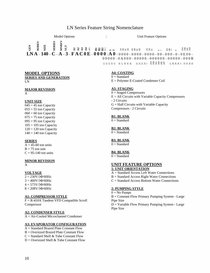
10
LN Series Feature String Nomenclature
Model Options Unit Feature Options
GE
N
MJ
RE
V
SIZ
E
SE
RIE
S
MN
RE
V
VL
T
A1
A2
A3
A4
A5
B1
B2
B3
B4
1
2
3A
3B
3C
3D
4A
4B
4C
4D
5A
5B
5C
5D
6
7
8A
8B
8C
9
10A
10B
10C
10D
LN A ndash 140 ndash C ndash A ndash 3 ndash F A C 0 E ndash 0 0 0 0 A 0 ndash 0 0 0 0 ndash 0 0 0 0 ndash 0 0 0 0 ndash 0 0 ndash 0 0 0 ndash 0 ndash 0 E 0 0 ndash
0 0 0 0 0 ndash 0 A 0 0 0 ndash 0 0 0 0 0 ndash 0 0 0 0 0 0 ndash 0 0 0 0 0 ndash 0 0 0 B
11
12
13
14
15
16
17
18
19
20
21
22
23
24
25
26A
26B
26C
26D
26E
26F
27
28
29
30
31
32
33
34
35
MODEL OPTIONS SERIES AND GENERATION
LN
MAJOR REVISION
A
UNIT SIZE
045 = 45 ton Capacity
055 = 55 ton Capacity
060 = 60 ton Capacity
075 = 75 ton Capacity
095 = 95 ton Capacity
105 = 105 ton Capacity
120 = 120 ton Capacity
140 = 140 ton Capacity
SERIES
A = 45-60 ton units
B = 75 ton unit
C = 95-140 ton units
MINOR REVISION
A
VOLTAGE
2 = 230V3Φ60Hz
3 = 460V3Φ60Hz
4 = 575V3Φ60Hz
8 = 208V3Φ60Hz
A1 COMPRESSOR STYLE
F = R-410A Tandem VFD Compatible Scroll
Compressor
A2 CONDENSER STYLE
A = Air-Cooled Microchannel Condenser
A3 EVAPORATOR CONFIGURATION
A = Standard Brazed Plate Constant Flow
B = Oversized Brazed Plate Constant Flow
C = Standard Shell amp Tube Constant Flow
D = Oversized Shell amp Tube Constant Flow
A4 COATING
0 = Standard
E = Polymer E-Coated Condenser Coil
A5 STAGING
0 = Staged Compressors
E = All Circuits with Variable Capacity Compressors
- 2 Circuits
G = Half Circuits with Variable Capacity
Compressors - 2 Circuits
B1 BLANK
0 = Standard
B2 BLANK
0 = Standard
B3 BLANK
0 = Standard
B4 BLANK
0 = Standard
UNIT FEATURE OPTIONS 1 UNIT ORIENTATION
A = Standard Access Left Water Connections
B = Standard Access Right Water Connections
C = Standard Access Bottom Water Connections
2 PUMPING STYLE
0 = No Pumps
B = Constant Flow Primary Pumping System - Large
Pipe Size
D = Variable Flow Primary Pumping System - Large
Pipe Size
11
LN Series Feature String Nomenclature
Model Options Unit Feature Options
GE
N
MJR
EV
S
IZE
SE
RIE
S
MN
RE
V
VL
T
A1
A2
A3
A4
A5
B1
B2
B3
B4
1
2 3A
3B
3C
3D
4A
4B
4C
4D
5A
5B
5C
5D
6
7
8A
8B
8C
9
10A
10B
10C
10D
LN A ndash 140 ndash C ndash A ndash 3 ndash F A C 0 E ndash 0 0 0 0 A 0 ndash 0 0 0 0 ndash 0 0 0 0 ndash 0 0 0 0 ndash 0 0 ndash 0 0 0 ndash 0 ndash 0 E 0 0 ndash
0 0 0 0 0 ndash 0 A 0 0 0 ndash 0 0 0 0 0 ndash 0 0 0 0 0 0 ndash 0 0 0 0 0 ndash 0 0 0 B
11
12
13
14
15
16
17
18
19
20
21
22
23
24
25
26A
26B
26C
26D
26E
26F
27
28
29
30
31
32
33
34
35
3A BUILDING PUMP CONFIGURATION
0 = No Building Pumps
A = 1 Pump + High Eff Motor
B = 1 Dual Pump + High Eff Motors
D = 1 Pump + VFD + High Eff Motor
E = 1 Dual Pump + 2 VFDs + High Eff Motors
K = 1 Pump + Field Installed VFD + High Eff Motor
L = 1 Dual Pump + 2 Field Installed VFDs + High
Eff Motors
3B BUILDING PUMP SERIES AND RPM
0 = No Building Pumps
A = 4360 (1170 nominal rpm)
B = 4360 (1760 nominal rpm)
C = 4360 (3520 nominal rpm)
D = 4380 (1170 nominal rpm)
E = 4380 (1760 nominal rpm)
F = 4380 (3520 nominal rpm)
K = 4382 (1170 nominal rpm)
L = 4382 (1760 nominal rpm)
M = 4382 (3520 nominal rpm)
3C PUMP SIZE
0 = No Building Pumps
A = 15B
B = 2B
C = 2D
D = 3D
E = 15x15x6
F = 2x2x6
G = 3x3x6
H = 4x4x6
J = 6x6x6
K = 15x15x8
L = 2x2x8
M = 3x3x8
N = 4x4x8
P= 5x5x8
Q = 6x6x8
R = 8x8x8
S = 2x2x10
T = 3x3x10
U = 4x4x10
V = 6x6x10
W = 8x8x10
Y = 4x4x115
Z = 5x5x115
1 = 6x6x115
2 = 8x8x115
3 = 4x4x13
4 = 6x6x13
5 = 8x8x13
12
LN Series Feature String Nomenclature
GE
N
MJR
EV
S
IZE
SE
RIE
S
MN
RE
V
VL
T
A1
A2
A3
A4
A5
B1
B2
B3
B4
1
2
3A
3B
3C
3D
4
A
4B
4C
4D
5A
5B
5C
5D
6
7
8A
8B
8C
9
1
0A
10
B
10
C
10D
LN A ndash 140 ndash C ndash A ndash 3 ndash F A C 0 E ndash 0 0 0 0 A 0 ndash 0 0 0 0 ndash 0 0 0 0 ndash 0 0 0 0 ndash 0 0 ndash 0 0 0 ndash 0 ndash 0 E 0 0 -
0 0 0 0 0 ndash 0 A 0 0 0 ndash 0 0 0 0 0 ndash 0 0 0 0 0 0 ndash 0 0 0 0 0 ndash 0 0 0 B
11
12
13
14
15
16
17
18
19
20
21
22
23
24
25
26A
26B
26C
26D
26E
26F
27
28
29
30
31
32
33
34
35
3D BUILDING PUMP MOTOR SIZE
0 = No Building Pumps
C = 1 hp
E = 2 hp
F = 3 hp
G = 5 hp
H = 75 hp
J = 10 hp
K = 15 hp
L = 20 hp
M = 25 hp
N = 30 hp
P = 40 hp
Q = 50 hp
4A BLANK
0 = Standard
4B BLANK
0 = Standard
4C BLANK
0 = Standard
4D BLANK
0 = Standard
5A BLANK
0 = Standard
5B BLANK
0 = Standard
5C BLANK
0 = Standard
5D BLANK
0 = Standard
6 REFRIGERATION OPTIONS
0 = Standard
A = Hot Gas Bypass on Non-Variable Capacity
Circuits
B = Hot Gas Bypass - All Circuits
7 REFRIGERATION ACCESSORIES
0 = Standard
A = Sight Glass
B = Compressor Isolation Valves
C = Option A + B
8A UNIT DISCONNECT TYPE
0 = Standard Single Point Power Block
A = Single Point Power Non-fused Disconnect
8B DISCONNECT SIZE
0 = Power Block
N = 100 amps
R = 150 amps
U = 225 amps
V = 250 amps
Z = 400 amps
3 = 600 amps
5 = 800 amps
7 = 1200 amps
8C BLANK
0 = Standard
9 ACCESSORIES
0 = Standard
B = Phase amp Brown Out Protection
10A UNIT CONTROL SEQUENCE
0 = Standard Controls
10B UNIT CONTROL SUPPLIER
E = MCS Controls
10C CONTROL SUPPLIER OPTIONS
0 = Standard
A = Touchscreen Interface
C = Modem
G = Option A + C
Model Options Unit Feature Options
13
LN Series Feature String Nomenclature
Model Options Unit Feature Options
GE
N
MJR
EV
S
IZE
SE
RIE
S
MN
RE
V
VL
T
A1
A2
A3
A4
A5
B1
B2
B3
B4
1
2
3A
3B
3C
3D
4A
4B
4C
4D
5A
5B
5C
5D
6
7
8A
8B
8C
9
10A
10B
10C
10
D
LN A ndash 140 ndash C ndash A ndash 3 ndash F A C 0 E ndash 0 0 0 0 A 0 ndash 0 0 0 0 ndash 0 0 0 0 ndash 0 0 0 0 ndash 0 0 ndash 0 0 0 ndash 0 ndash 0 E 0 0 ndash
0 0 0 0 0 ndash 0 A 0 0 0 ndash 0 0 0 0 0 ndash 0 0 0 0 0 0 ndash 0 0 0 0 0 ndash 0 0 0 B
11
12
13
14
15
16
17
18
19
20
21
22
23
24
25
26
A
26
B
26
C
26D
26E
26F
27
28
29
30
31
32
33
34
35
10D BMS CONNECTION amp DIAGNOSTICS
0 = None
A = BACnet IP
B = BACnet MSTP
C = Modbus IP
D = Modbus RTU
E = Lontalk
H = No BMS Connection with Diagnostics
J = BACnet IP with Diagnostics
K = BACnet MSTP with Diagnostics
L = Modbus IP with Diagnostics
M = Modbus RTU with Diagnostics
N = Lontalk with Diagnostics
11 BLANK
0 = Standard
12 VESTIBULE ACCESSORIES
0 = Standard
C = Vestibule Heating (Electric)
13 MAINTENANCE ACCESSORIES
0 = Standard
A = 115VAC Convenience Outlet Factory Wired
B = 115VAC Convenience Outlet Field Wired
C = Service Lights
F = Options A + C
J = Options B + C
14 BLANK
0 = Standard
15 CODE OPTIONS
0 = Standard ETL USA Listing
A = Chicago Code
B = ETL USA + Canada Listing
16 SHIPPING SPLITS
0 = One Piece Unit
17 AIR-COOLED CHILLER ACCESSORIES
H = Cond Coil Guards + Three Phase Cond Fan
Motor + Fan Cycling- 35degF Low Ambient
J = Cond Coil Guards + VFD Cond Fan Head
Pressure Control - 0degF Low Ambient
18 BLANK
0 = Standard
19 BLANK
0 = Standard
20 BLANK
0 = Standard
21 BLANK
0 = Standard
22 BLANK
0 = Standard
23 BLANK
0 = Standard
24 CHILLER ACCESSORIES 1
0 = Standard
A = Glycol Chiller
C = Thermometers amp Pressure Gauges
G = Option A + C
25 BLANK
0 = Standard
26A BLANK
0 = Standard
26B BLANK
0 = Standard
26C BLANK
0 = Standard
14
LN Series Feature String Nomenclature
Model Options Unit Feature Options
GE
N
MJR
EV
S
IZE
SE
RIE
S
MN
RE
V
VL
T
A1
A2
A3
A4
A5
B1
B2
B3
B4
1
2
3A
3B
3C
3D
4A
4B
4C
4D
5A
5B
5C
5D
6
7
8A
8B
8C
9
10A
10B
10C
10D
LN A ndash 140 ndash C ndash A ndash 3 ndash F A C 0 E ndash 0 0 0 0 A 0 ndash 0 0 0 0 ndash 0 0 0 0 ndash 0 0 0 0 ndash 0 0 ndash 0 0 0 ndash 0 ndash 0 E 0 0 ndash
0 0 0 0 0 ndash 0 A 0 0 0 ndash 0 0 0 0 0 ndash 0 0 0 0 0 0 ndash 0 0 0 0 0 ndash 0 0 0 B
11
12
13
14
15
16
17
18
19
20
21
22
23
24
25
26A
26B
26C
26
D
26
E
26
F
27
28
29
30
31
3
2
33
34
35
26D BLANK
0 = Standard
26E BLANK
0 = Standard
26F BLANK
0 = Standard
27 BLANK
0 = Standard
28 BLANK
0 = Standard
29 BLANK
0 = Standard
30 BLANK
0 = Standard
31 BLANK
0 = Standard
32 BLANK
0 = Standard
33 WARRANTY
0 = Standard Warranty
D = Compressor Warranty Years 2-5
34 CABINET MATERIAL
0 = Standard - Double Wall + R-13 Foam Insulation
35 PAINT amp SPECIAL PRICING
AUTHORIZATIONS
B = Premium AAON Gray Paint Exterior
E = Premium AAON Gray Paint Exterior + Shrink
Wrap
X = Special Pricing Authorization + Premium AAON
Gray Paint Exterior
1 = SPA + Premium AAON Gray Paint Exterior +
Shrink Wrap
4 = Special Pricing Authorization + Special Exterior
Paint Color
7 = SPA + Special Exterior Paint Color + Shrink
Wrap
15
General Information
AAON LN Series chillers are complete self-
contained liquid chilling units They are
assembled wired charged and run-tested
Models are available for air-cooled
applications Chiller primary pumping
packages are available as optional features
Codes and Ordinances
LN Series units have been tested and
certified by ETL in accordance with UL
Safety Standard 1995CSA C222 No 236
System should be sized in accordance with
the American Society of Heating
Refrigeration and Air Conditioning
Engineers Handbook
Installation of LN Series units must conform
to the ICC standards of the International
Mechanical Code the International Building
Code and local building plumbing and
waste water codes All appliances must be
electrically grounded in accordance with
local codes or in the absence of local codes
the current National Electric Code
ANSINFPA 70 or the current Canadian
Electrical Code CSA C221
Receiving Unit
When received the unit should be checked
for damage that might have occurred in
transit If damage is found it should be noted
on the carrierrsquos Freight Bill A request for
inspection by carrierrsquos agent should be made
in writing at once Nameplate should be
checked to ensure the correct model sizes and
voltages have been received to match the job
requirements
If repairs must be made to damaged goods
then the factory should be notified before any
repair action is taken in order to protect the
warranty Certain equipment alteration
repair and manipulation of equipment
without the manufacturerrsquos consent may void
the product warranty Contact AAON
Technical Support for assistance with
Improper installation adjustment alteration service or maintenance can cause property damage personal injury or loss of life Startup and service must be performed by a Factory Trained Service Technician
WARNING
The Clean Air Act of 1990 bans the intentional venting of refrigerant as of July 1 1992 Approved methods of recovery recycling or reclaiming must be followed
CAUTION
Coils and sheet metal surfaces present sharp edges and care must be taken when working with equipment
Failure to observe the following instructions will result in premature failure of your system and possible voiding of the warranty
WARNING
WARNING
16
handling damaged goods repairs and freight
claims (918) 382-6450
Storage
If installation will not occur immediately
following delivery store equipment in a dry
protected area away from construction traffic
and in the proper orientation as marked on the
packaging with all internal packaging in
place Secure all loose-shipped items
Chiller
Failure to observe the following instructions
will result in premature failure of your
system and possible voiding of the warranty
Never turn off the main power supply to the
unit except for complete shutdown When
power is cut off from the unit any
compressors using crankcase heaters cannot
prevent refrigerant migration This means the
compressor will cool down and liquid
refrigerant may accumulate in the
compressor The compressor is designed to
pump refrigerant gas and damage may occur
when power is restored if liquid enters the
compressor
Before unit operation the main power switch
must be turned on for at least 24 hours for
units with compressor crankcase heaters
This will give the crankcase heater time to
clear any liquid accumulation out of the
compressor before it is required to run
Rotation must be checked on all MOTORS AND COMPRESSORS of three phase units All motors to include and not be limited to pump motors and condenser fan motors should all be checked by a qualified service technician at startup and any wiring alteration should only be made at the unit power connection
CAUTION
Scroll compressors are directional and will be damaged by operation in the wrong direction Low pressure switches on compressors have been disconnected after factory testing Rotation should be checked by a qualified service technician at startup using suction and discharge pressure gauges and any wiring alteration should only be made at the unit power connection
CAUTION
CRANKCASE HEATER OPERATION
Units may be equipped with compressor crankcase heaters which should be energized at least 24 hours prior to cooling operation to clear any liquid refrigerant from the compressors
CAUTION
COMPRESSOR CYCLING
3 MINUTE MINIMUM OFF TIME To prevent motor overheating compressors must cycle off for a minimum of 3 minutes
3 MINUTE MINIMUM ON TIME To maintain the proper oil level compressors must cycle on for a minimum of 3 minutes The cycle rate must not exceed 6 starts per hour
WARNING
17
Never cut off the main power supply to the
unit except for complete shutdown Always
control the system from the building
management system or control panel never
at the main power supply (except for
emergency or for complete shutdown of the
system)
Scroll compressors must be on a minimum of
3 minutes and off for a minimum of 3
minutes The cycle rate must be no more than
6 starts per hour
The chiller is furnished with a pressure
differential switch that is factory installed
between the chilled water supply and return
connections This sensor must not be
bypassed since it provides a signal to the unit
controller that water flow is present in the
heat exchanger and the unit can operate
without the danger of freezing the liquid
Compressor life will be seriously shortened
by reduced lubrication and the pumping of
excessive amounts of liquid oil and liquid
refrigerant
Wiring Diagrams
A complete set of unit specific wiring
diagrams in both ladder and point-to-point
form are laminated in plastic and located
inside the control compartment door
General Maintenance
When the initial startup is made and on a
periodic schedule during operation it is
necessary to perform routine service checks
on the performance of the chiller This
includes reading and recording suction
pressures and checking for normal sub-
cooling and superheat See the air-cooled
condenser sections in this manual for specific
details
Chiller Primary Pumping
Primary pumping uses a single pump to move
water (or glycol) through the chiller barrel
and back to the building This pumping
package provides a constant or variable flow
of water to the system The pump is activated
whenever the chiller is given a run signal
Water enters the unit through the return water
piping and then travels through an air
separator to remove any air that is entrapped
in the water Following this the water flows
through a suction guide with strainer The
end of the suction guide is removable for
strainer access The strainer assembly is
composed of two parts the operational
strainer and the startup strainer (located
inside the operational strainer) which is to be
removed 24 hours after startup
The pump is installed after the suction guide
and before a combination valve (Flo-Trex)
This combination valve acts as isolation
valve check valve and flow balancing valve
The shell and tube or brazed plate evaporator
is placed after the combination valve in the
water circuit with a flow switch installed
across its inlet and outlet This flow switch
closes when the velocity is above 07 feet per
second The closing flow switch signals the
control system to indicate flow through the
heat exchanger and allow cooling to activate
as required to maintain the setpoint The
water exiting the chiller evaporator leaves the
unit through the water out connection
18
Automatic Air Vent
There is an automatic air vent installed at the
high point of the system inside the pumping
package compartment The air vent valve
must be in the proper position for operation
Ensure that the small vent cap is loosened two
turns from the closed position allowing air to
be vented from the system It is advisable to
leave the cap on to prevent impurities from
entering the valve See appendix for
additional information
Dual Pumps
When redundant pumping is required factory
installed dual pumps can be ordered A dual
pump is a pump with two independent motors
and pumps in a single casing This dual pump
has a swing split-flapper valve in the
discharge port to prevent liquid recirculation
when only one pump is operating Isolation
valves in the casing allow one pump to be
isolated and removed for service while the
other pump is still operating
The controls package will activate the pump
when the unit is given a run command If the
controls do not recognize flow in 60 seconds
the second pump will be activated and an
alarm signal will be generated If the second
pump does not activate the cooling will be
locked out See appendix for additional
information
Pressure Gauges and Thermometers
Pressure gauges and thermometers are
available as a factory installed option
Thermometers are installed on the inlet and
outlet of the unit One pressure gauge is
installed at each pump This pressure gauge
is connected in three places to the water
piping before the suction guidestrainer after
the suction guide and before the pump and
after the pump There is also a needle valve
at each of these points to isolate the pressure
To measure the pressure at any given point
open the needle valve at that point and close
the other two needle valves One gauge is
used so that the calibration of the pressure
gauge is irrelevant in the calculation of the
differential pressure
Pipe Insulation
The water piping and components on units
with pumping packages are not insulated at
the factory Insulation should be installed on
the water piping after the system has been
checked for leaks
19
Installation
Chiller Placement
The AAON LN Series is designed for
outdoor applications and mounting at ground
level or on a rooftop It must be placed on a
level and solid foundation that has been
prepared to support its weight
The placement relative to the building air
intakes and other structures must be carefully
selected Be sure to observe the dimensions
that are on the rating plate of the chiller for
operational and service clearances
Table 1 - Service Clearances
Location Unit Size
45-140 tons
Front -
(Controls Side) 72rdquo
Back 72rdquo
Ends 96rdquo
Top Unobstructed
Condenser coils and fans must be free of any
obstructions in order to start and operate
properly with a correct amount of airflow
For proper unit operation the immediate area
around condenser must remain free of debris
that may be drawn in and obstruct airflow in
the condensing section
Consideration must be given to obstruction
caused by snow accumulation when placing
the unit
Curb and Steel Mount Installation
Make openings in the roof decking large
enough to allow for water piping electrical
penetrations and workspace only Do not
make openings larger than necessary Set the
curb to coincide with the openings Make
sure curb is level
If the LN is installed on a curb use a curb cap
for the open area under the condenser section
Unit specific curb drawing is included with
job submittal See SMACNA Architectural
Sheet Metal Manual for curb installation
details
Units require rail support along all four sides
of the unit base
When installed at ground level a one-piece
concrete slab should be used with footings
that extend below the frost line Care must
also be taken to protect the coil and fins from
damage due to vandalism or other causes
If unit is elevated a field supplied catwalk is
recommended to allow access to unit service
doors
This unit ships with a curb gasket that is 1frac14rdquo
wide and 1frac12rdquo tall It is recommended that this
or another similar gasket be used between the
curb and the unit to reduce vibration from the
unit to the building
All roofing work should be performed by competent roofing contractors to avoid any possible leakage
CAUTION
Figure 1 - LN Base
20
Figure 2 - Curb Mounting with Dimensions
Figure 3 - Steel Mounting Rail with
Dimensions
Table 2 - Mounting Dimensions
Tons A B C D
45-140 142rdquo 138rdquo 134rdquo 139rdquo
Figure 2
Figure 3
Lifting and Handling
If cables or chains are used to hoist the unit
they must be the same length and care should
be taken to prevent damage to the cabinet
See Figure 5 and Figure 6 for additional
information
Before lifting unit be sure that all shipping
material has been removed from unit Secure
hooks and cables at all lifting points lugs
provided on the unit
Hoist unit to a point directly above the curb
or mounting rail Be sure that the gasket
material has been applied to the curb or
mounting rail
Carefully lower and align unit with utility and
duct openings Lower the unit until the unit
skirt fits around the curb Make sure the unit
is properly seated on the curb and is level
Figure 4 - Lifting Points
21
Figure 5 - Lifting Detail of a 45-60 ton Unit
Figure 6 - Lifting Detail of a 75-140 ton Unit
Lifting slot locations are unit specific
Unit must be rigged at all marked lifting points
22
Water Connection
Connect the supply and return water lines
The connection size is listed on the unit rating
sheet along with the designed volumetric
flow rate The maximum operating pressure
for AAON LN Series units is 125 psi
Mounting Isolation
For roof mounted applications or anytime
vibration transmission is a factor vibration
isolators may be used
Access Doors
Lockable access door is provided to the
compressor and control compartment A
separate access door is also provided to the
pumping package compartment
A light switch with service lights is provided
on the wall of the compressor and control
compartment
End Flashing Installation
On all LN Series units the cabinet width will
overhang the shipping trailer on each side
In order to secure and protect the unit during
transit the sheet metal end flashings have
been removed from the unit The slot created
at the base of each end of the unit allows the
unit to set firmly on the trailer deck
Sheet metal flashings are shipped loose with
the unit and once the unit is set into place the
flashings must be installed on each end of the
unit to complete the finished seal at the base
The flashings are unit specific and designed
to cover the slot at each end of the unit to
prevent water run-off into the curb
Failure to attach and seal the end of unit with
the flashings may result in water leakage into
the curb
Figure 7 - Factory Supplied End Flashings
PVC (Polyvinyl Chloride) and CPVC (Chlorinated Polyvinyl Chloride) are vulnerable to attack by certain chemicals Polyolester (POE) oils used with R-410A and other refrigerants even in trace amounts in a PVC or CPVC piping system will result in stress cracking of the piping and fittings and complete piping system failure
CAUTION
The chiller must be operated only with liquid flowing through the evaporators
WARNING
Installing Contractor is responsible for proper sealing of the water piping entries into the unit Failure to seal the entries may result in damage to the unit and property
CAUTION
23
Low Ambient Operation
If the chiller is ordered for a Low Ambient
application the liquid system must use a
glycol solution and the piping must be
insulated to be prepared for freezing
conditions Care must be taken in the source
of electrical power for the heating tape and
thermostat
Electrical
The single point electrical power connections
are made in the electrical control
compartment
The microprocessor control furnished with
the unit is supplied with its own power supply
factory wired to the main power of the
outdoor mechanical room
Verify the unit nameplate voltage agrees with
the power supply Connect power and control
field wiring as shown on the unit specific
wiring diagram provided with the unit
Size supply conductors based on the unit
MCA rating Supply conductors must be
rated a minimum of 167degF (75degC)
Route power and control wiring separately
through the utility entry Do not run power
and signal wires in the same conduit
Protect the branch circuit in accordance with
code requirements The unit must be
electrically grounded in accordance with
local codes or in the absence of local codes
the current National Electric Code
ANSINFPA 70 or the current Canadian
Electrical Code CSA C221
Power wiring is to the unit terminal block or
main disconnect All wiring beyond this point
has been done by the manufacturer and
cannot be modified without effecting the
units agencysafety certification
Figure 8 - Front View of Utility Entry and
Power Switch from Control Compartment
Electric shock hazard Before attempting to perform any installation service or maintenance shut off all electrical power to the unit at the disconnect switches Unit may have multiple power supplies Failure to disconnect power could result in dangerous operation serious injury death or property damage
WARNING
In order to prevent water leakage into the roof curb the factory provided sheet metal flashings MUST BE attached to the unit base to cover the shipping slots at both ends of the unit
CAUTION
24
Startup technician must check for proper
motor rotation and check fan motor amperage
listed on the motor nameplate is not
exceeded Motor overload protection may be
a function of the variable frequency drive and
must not be bypassed
Note All units are factory wired for
208230V 460V or 575V If unit is to be
connected to a 208V supply the transformer
must be rewired to 208V service For 208V
service interchange the yellow and red
conductor on the low voltage control
transformer
Red-Black for 208V
Yellow-Black for 230V
Wire control signals to the unitrsquos low voltage
terminal block located in the controls
compartment All wiring beyond this point
has been completed by the manufacturer and
cannot be modified without effecting the
unitrsquos agencysafety certification
If any factory installed wiring must be
replaced use a minimum 221degF (105degC) type
AWM insulated conductors
Supply voltage must be within the minmax
range shown on the unit nameplate Available
short circuit current should not exceed the
short circuit current rating (SCCR) shown on
the unit nameplate
Three phase voltage imbalance will cause
motor overheating and premature failure
The maximum allowable imbalance is 5
Voltage imbalance is defined as 100 times the
maximum deviation from the average voltage
divided by the average voltage
Example
(218V+237V+235V)3 = 230V then
100(230V-218V)230V = 52 which
exceeds the allowable imbalance
Check voltage imbalance at the unit
disconnect switch and at the compressor
terminal Contact your local power company
for line voltage corrections
Three phase voltage imbalance will cause motor overheating and premature failure
CAUTION
Scroll compressors are directional and will be damaged by operation in the wrong direction Low pressure switches on compressors have been disconnected after factory testing Rotation should be checked by a qualified service technician at startup using suction and discharge pressure gauges and any wiring alteration should only be made at the unit power connection
Installing Contractor is responsible for proper sealing of the electrical and gas entries into the unit Failure to seal the entries may result in damage to the unit and property
CAUTION CAUTION
25
Variable Speed Compressors
Variable speed compressors should not be
operated outside the factory determined
frequency range The factory determined
compressor VFD frequency range is given
below in Table 3
Table 3- Tandem Circuited Variable Speed
Compressor VFD Frequency Range
Model (LN-) Compressor VFD
Range (Hz)
208V 230V 460V and 575V Units
045 055 060 45-65Hz
075 45-70Hz
095 105 120 35-60 Hz
140 35-65 Hz
No variable speed compressor shall operate below 35 Hz Operating variable speed compressors outside the frequency range specified in this manual voids all warranties and may result in compressor failure
CAUTION
Rotation must be checked on all MOTORS AND COMPRESSORS of three phase units Condenser fan motors should all be checked by a qualified service technician at startup and any wiring alteration should only be made at the unit power connection Variable frequency drives are programmed to automatically rotate the fan in the correct rotation Do not rely on fans with variable frequency drives for compressor rotation
CAUTION
26
Startup (See back of the manual for startup form)
Before the startup of the chiller be sure that
the following items have been checked
1 Verify that electrical power is available to
the unit
2 Verify that any remote stopstart device
connected to the chiller controller is
requesting the chiller to start
3 Verify that liquid flow is present through
the chiller from the building
4 There should be a building load of at least
25 of the chiller capacity in order to
properly check operation
5 With the main power switch off review
the MCS Controller Manual provided
with the chiller Understand the keypad
functions how to set the leaving water
temperature setpoint and how to initiate
the Run State
Use the general check list at the top of the
startup form to make a last check that all the
components are in place water flow is
present and the power supply is energized
Using the controller keypad individually set
the outputs in ldquoManual Onrdquo to confirm relay
closure and compressor operation
Cycle through all the compressors to confirm
that all are operating within tolerance
While performing the check use the startup
form to record observations of compressor
amps and refrigerant pressures
When all is running properly place the
controller in the Run mode and observe the
system until it reaches a steady state of
operation
Note For more information on programming
the controller refer to the MCS Controller
manual provided with the chiller
Electric shock hazard Shut off all electrical power to the unit to avoid shock hazard or injury from rotating parts
WARNING
Improper installation adjustment alteration service or maintenance can cause property damage personal injury or loss of life Startup and service must be performed by a Factory Trained Service Technician
WARNING
Rotation must be checked on all MOTORS AND COMPRESSORS of three phase units All motors to include and not be limited to pump motors and condenser fan motors should all be checked by a qualified service technician at startup and any wiring alteration should only be made at the unit power connection
CAUTION
Before completing installation a complete operating cycle should be observed to verify that all components are functioning properly
CAUTION
27
Axial Flow Condenser Fans
Multi-Wing Z Series Aluminum Fan Blade
Pitch Angle Setting Instructions
1 Maintain the balance of fan
Mark the hub castings across a joint so the
fan hub can be reassembled in the same
orientation
Mark the location of any balancing weight
Balancing weight will be on the outer bolt
circle in the form of washers andor longer
bolts or an additional balancing nut
Number the blades and blade sockets so that
they are replaced into their original position
Figure 9 - Fan with the HUB on the top and
RET on the bottom
2 Determine the direction of rotation
Right R is clockwise when facing the
discharge side of the fan and Left L is
counterclockwise when facing the discharge
side of the fan
3 Determine the bushing mount location
The bushing mount is the center section of the
hub through which the fan is mounted to the
shaft and typically contains either setscrews
or a center-tapered hole where the bushing
inserts
Location A is with the bushing mount on air
inlet side of the fan
Location B is with the bushing mount on air
discharge side of the fan
Figure 10 - Bushing Mount Location
4 Determine the pin location groove
Disassemble fan on a flat surface and note in
which groove the pin is located
Figure 11 - RET with Pin in Groove 4
Bushing
Mount
A B Bushing
Mount
Bushing Bushing
1 2 3 4
28
5 Determine whether the pin is in the HUB
or RET
Figure 12 - Fan HUB and RET Castings
6 Determine the current blade pitch and the pin location for the new blades
Table 4 - ReturnExhaust Fan Pin Location
Type Bushing
Mount
Blade Pitch Angle
20deg 25deg 28deg 30deg 33deg 35deg 38deg 40deg 45deg 50deg
5Z A - RET - RET RET RET HUB HUB HUB HUB
B - HUB - HUB HUB HUB RET RET RET RET
Table 5 - ReturnExhaust Fan Pin Location
Type Rot Blade Pitch Angle
20deg 25deg 28deg 30deg 33deg 35deg 38deg 40deg 45deg 50deg
5Z R - 4 - 3 2 1 4 3 2 1
L - 1 - 2 3 4 1 2 3 4
7 Replace fan blades in the new pin
location and reassemble the fan
Replace the blades with the pin in the 1 2 3
or 4 groove position of either the HUB or
RET Assemble the fan making sure to place
the blades in their previous blade sockets to
match up the previous orientation of HUB
and RET and to replace any balancing
weights in their previous locations Tighten
bolts in a cross pattern to 5-6 ft-lbs of torque
29
Multi-Wing W Series Black Glass
Reinforced Polypropylene Fan Blade Pitch
Angle Setting Instructions
Contact the AAON parts department to
acquire the new pitch pins for the fan blades
Note original position of retaining plates
center boss and all hardware including
additional hardware used for balancing
1 Remove all the bolts and nuts
2 Determine blade rotation ndash on the concave
side of the blade is a blade marking showing
6WR 6WL 7WL 7WR or 9WR The ldquoLrdquo
and ldquoRrdquo denote the rotation of the blade
3 Replace the pitch insert in the blade root
with an insert of the desired pitch
Figure 13 - Pitch Insert
4 Replace blades to their original location
5 Replace all nuts bolts and washers on the
fan hub
6 Replace retaining plates and center boss to
original location
7 Tighten nuts and bolts to 14 ft-lbs of
torque
Fan Assembly Bushings
The fan assembly bushings should be
tightened to the specifications listed in the
following table
Table 6 - Fan Assembly Bushing Torque
Specifications
Bushing Tightening Torque
(in-lbs)
H X 1125 95
H X 1375 95
SH X 1125 108
SH X 1375 108
SD X 1125 108
SD X 1375 108
SD X 1625 108
SD X 1875 108
SK X 2125 180
30
Maintenance
General
Qualified technicians must perform routine
service checks and maintenance This
includes reading and recording the
condensing and suction pressures and
checking for normal sub-cooling and
superheat
Air-cooled chillers require maintenance
schedulesprocedures Unit specific
instructions are included in this manual
Compressors
The scroll compressors are fully hermetic and
require no maintenance except keeping the
shell clean
Refrigerant Suction Line Filter
Each refrigerant circuit contains a
replaceable core suction line filter One
month after start-up remove the filter
element
The replaceable core suction filters are
provided with pressure taps and shutoff
valves for isolation when removing the filter
For safety purposes a service manifold must
be attached prior to filter maintenance
Suction Filter Removal Instructions
1 Shut down operation of the unit
2 Close both shut-off valves to isolate
the suction filter
3 Reclaim the refrigerant from the
suction filter section
4 Remove the bolts from the suction
filter end plate
5 Remove the pleated filter assembly
Prior to filter core service a service manifold MUST BE attached to in and out pressure connections to assure no pressure exists during filter maintenance Non-compliance could result in injury or violation of EPA regulations
Service gauges MUST BE connected before operating the isolation valves for the replaceable core filter
WARNING
WARNING
31
6 Replace the suction filter end plate
and bolts
7 Evacuate the suction filter assembly
to 500 microns
8 Open both shut-off valves
Adjusting Refrigerant Charge
All AAON chillers are shipped with a full
factory charge Periodically adjusting the
charge of a system may be required
Adjusting the charge of a system in the field
must be based on determination of liquid sub-
cooling and evaporator superheat On a
system with an expansion valve liquid sub-
cooling is more representative of the charge
than evaporator superheat but both
measurements must be taken
Before Charging
Refer to the unit nameplate as a reference
when determining the proper refrigerant
charge
Unit being charged must be at or near full
load conditions before adjusting the charge
Units equipped with hot gas bypass must
have the hot gas bypass valve closed to get
the proper charge
After adding or removing charge the system
must be allowed to stabilize typically 10-15
minutes before making any other
adjustments
The type of unit and options determine the
ranges for liquid sub-cooling and evaporator
superheat Refer to Table 7 when determining
the proper sub-cooling
For units equipped with low ambient (0degF)
option see the special charging instructions at
the end of this section
Checking Liquid Sub-cooling
Measure the temperature of the liquid line as
it leaves the condenser coil
Read the gauge pressure at the liquid line
close to the point where the temperature was
taken You must use liquid line pressure as it
will vary from discharge pressure due to
condenser coil pressure drop
Convert the pressure obtained to a saturated
temperature using the appropriate refrigerant
temperature-pressure chart
Subtract the measured liquid line temperature
from the saturated temperature to determine
the liquid sub-cooling
Compare calculated sub-cooling to the table
below for the appropriate unit type and
options
The Clean Air Act of 1990 bans the intentional venting of refrigerant (CFCrsquos and HCFCrsquos) as of July 1 1992 Approved methods of recovery recycling or reclaiming must be followed Fines andor incarceration may be levied for non-compliance
CAUTION
Polyolester (POE) and Polyvinylether (PVE) oils are two types of lubricants used in hydrofluorocarbon (HFC) refrigeration systems Refer to the compressor label for the proper compressor lubricant type
CAUTION
32
Checking Evaporator Superheat
Measure the temperature of the suction line
close to the compressor
Read gauge pressure at the suction line close
to the compressor
Convert the pressure obtained to a saturated
temperature using the appropriate refrigerant
temperature-pressure chart
Subtract the saturated temperature from the
measured suction line temperature to
determine the evaporator superheat
For refrigeration systems with tandem scroll
compressors it is critical that the suction
superheat setpoint on the expansion valve is
set with one compressor running The suction
superheat should be 10-13degF with one
compressor running The suction superheat
will increase with both compressors in a
tandem running Inadequate suction
superheat can allow liquid refrigerant to
return to the compressors which will wash the
oil out of the compressor Lack of oil
lubrication will destroy a compressor Liquid
sub-cooling should be measured with both
compressors in a refrigeration system
running
Compare calculated superheat to Table 7 for
the appropriate unit type and options
Table 7 - Acceptable Refrigeration Circuit
Values
Air-Cooled Chiller with Scroll
Compressors
Sub-Cooling2 12-18degF
Superheat1 10-15degF 1 One compressor running in tandem 2 Two compressors running in tandem
Adjusting Sub-cooling and Superheat
Temperatures
The system is overcharged if the sub-cooling
temperature is too high and the evaporator is
fully loaded (low loads on the evaporator
result in increased sub-cooling) and the
evaporator superheat is within the
temperature range as shown in Table 7 (high
superheat results in increased sub-cooling)
Correct an overcharged system by reducing
the amount of refrigerant in the system to
lower the sub-cooling
The system is undercharged if the superheat
is too high and the sub-cooling is too low
Correct an undercharged system by adding
refrigerant to the system to reduce superheat
and raise sub-cooling
If the sub-cooling is correct and the superheat
is too high the expansion valve may need
adjustment to correct the superheat
Expansion valves must be adjusted to approximately 10-15degF of suction superheat Failure to have sufficient superheat will damage the compressor and void the warranty
CAUTION
DO NOT OVERCHARGE Refrigerant overcharging leads to excess refrigerant in the condenser coils resulting in elevated compressor discharge pressure
CAUTION
33
Table 8 - R-410A Refrigerant Temperature-Pressure Chart
F psig F psig F psig F psig F psig
20 783 50 1422 80 2349 110 3641 140 5401
21 800 51 1448 81 2386 111 3691 141 5470
22 818 52 1474 82 2423 112 3742 142 5539
23 836 53 1501 83 2460 113 3794 143 5609
24 854 54 1528 84 2498 114 3846 144 5679
25 872 55 1555 85 2537 115 3899 145 5751
26 891 56 1582 86 2575 116 3952 146 5823
27 910 57 1610 87 2614 117 4005 147 5896
28 929 58 1638 88 2654 118 4059 148 5969
29 949 59 1667 89 2694 119 4114 149 6044
30 968 60 1696 90 2735 120 4169 150 6119
31 988 61 1725 91 2776 121 4225
32 1009 62 1754 92 2817 122 4282
33 1029 63 1784 93 2859 123 4339
34 1050 64 1815 94 2901 124 4396
35 1071 65 1845 95 2944 125 4454
36 1092 66 1876 96 2987 126 4513
37 1114 67 1907 97 3030 127 4573
38 1136 68 1939 98 3075 128 4632
39 1158 69 1971 99 3119 129 4693
40 1181 70 2004 100 3164 130 4754
41 1203 71 2036 101 3210 131 4816
42 1227 72 2070 102 3256 132 4878
43 1250 73 2103 103 3302 133 4941
44 1274 74 2137 104 3349 134 5005
45 1298 75 2171 105 3396 135 5069
46 1322 76 2206 106 3444 136 5134
47 1347 77 2241 107 3493 137 5200
48 1372 78 2277 108 3542 138 5266
49 1397 79 2313 109 3591 139 5333
34
Lubrication
All original motors and bearings are
furnished with an original factory charge of
lubrication Certain applications require
bearings be re-lubricated periodically The
schedule will vary depending on operating
duty temperature variations or severe
atmospheric conditions
Bearings should be re-lubricated at normal
operating temperatures but not when
running
Rotate the fan shaft by hand and add only
enough grease to purge the seals DO NOT
OVERLUBRICATE
Air-Cooled Condenser
The air-cooled condenser section rejects heat
by passing outdoor air over the fin tube coils
for cooling of the hot refrigerant gas from the
compressors The heated air will discharge
from the top of the section through the axial
flow fans
The condenser coils should be inspected
yearly to ensure unrestricted airflow If the
installation has a large amount of airborne
dust or other material the condenser coils
should be cleaned according to the
microchannel coil cleaning section
Brazed Plate Heat Exchanger Cleaning
Because of a normally high degree of
turbulence in brazed plate heat exchangers
for many applications the heat exchanger
channels are self-cleaning For applications
that are not self-cleaning (ie hard water at
high temperatures etc) or applications where
additional cleaning is desired it is possible to
clean the brazed plate heat exchanger by
circulating a cleaning liquid
Use a tank with weak acid 5 phosphoric
acid (H3PO4) or if the exchanger is
frequently cleaned 5 oxalic acid (H2C2O4)
Pump the cleaning liquid through the
exchanger For optimum cleaning the
cleaning solution flow rate should be a
minimum of 15 times the normal flow rate
preferably in a back-flush mode After
cleaning the heat exchanger must be rinsed
with clean water A solution of 1-2 sodium
hydroxide (NaOH) or sodium bicarbonate
(NaHCO) before the last rinse ensures that all
acid is neutralized
E-Coated Coil Cleaning
Documented quarterly cleaning of e-coated
coils is required to maintain coating warranty
coverage
Surface loaded fibers or dirt should be
removed prior to water rinse to prevent
restriction of airflow If unable to back wash
the side of the coil opposite of the coils
entering air side then surface loaded fibers or
dirt should be removed with a vacuum
cleaner If a vacuum cleaner is not available
a soft non-metallic bristle brush may be used
In either case the tool should be applied in
the direction of the fins Coil surfaces can be
easily damaged (fin edges bent over) if the
tool is applied across the fins
Use of a water stream such as a garden hose
against a surface loaded coil will drive the
fibers dirt and salts into the coil This will
make cleaning efforts more difficult Surface
loaded fibers must be completely removed
prior to using low velocity clean water rinse
Electric shock hazard Shut off all electrical power to the unit to avoid shock hazard or injury from rotating parts
WARNING
35
Quarterly cleaning is required to maintain
warranty coverage and is essential to
maintain the life of an E-coated coil Coil
cleaning shall be part of the units regularly
scheduled maintenance procedures
Failure to clean an E-coated coil on the
prescribed quarterly cycle will void the
warranty and may result in reduced
efficiency and durability in the environment
A routine two-step quarterly coil cleaning is
required to maintain warranty
Step one is to clean the coil with the below
approved coil cleaner (see approved products
list under the Recommended Coil Cleanersrdquo
section
Step two is to use the approved saltchloride
remover under the Recommended Chloride
Removerrdquo section to dissolve soluble salts
and revitalize the unit It is very important
when cleaning andor rinsing not to exceed
130degF and potable water pressure is less than
100 psig to avoid damaging the unit and coil
fin edges
For routine quarterly cleaning first clean the
coil with the below approved coil
cleaner After cleaning the coils with the
approved cleaning agent use the approved
chloride remover to remove soluble salts and
revitalize the unit
Recommended Coil Cleaner ndash Step 1
GulfCoatTM Coil Cleaner assuming it is
used in accordance with the manufacturers
directions on the container for proper mixing
and cleaning has been approved for use on
E-coated coils to remove mold mildew dust
soot greasy residue lint and other
particulate Never use any cleaners that are
not approved
Recommended Chloride Remover ndash Step 2
CHLORRIDreg Concentrate assuming it
is used in accordance with the manufacturers
directions on the container for proper mixing
has been approved for use on E-coated coils
to remove chloridessalts amp sulfates Never
use any chloride removers that are not
approved
Warranty Protection ndash Step 1
Complete the coil cleaning following these
steps
1 Ensure that the power to the unit is off
and locked out
2 Clean the area around the unit if
needed to ensure leaves grass or
High velocity water from a pressure washer or compressed air should only be used at a very low pressure to prevent fin andor coil damages The force of the water or air jet may bend the fin edges and increase airside pressure drop Reduced unit performance or nuisance unit shutdowns may occur
Harsh chemicals household bleach or acid cleaners should not be used to clean e-coated coils These cleaners can be very difficult to rinse out of the coil and can accelerate corrosion and attack the e-coating If there is dirt below the surface of the coil use the recommended coil cleaners
CAUTION
CAUTION
36
loose debris will not be blown into the
coil
3 Remove panels or tops as required
gaining access to the coil(s) to be
cleaned
4 Using a pump up sprayer fill to the
appropriate level with potable water
and add the correct amount of
approved cleaner as per manufacture
instructions leaving room for the
pump plunger to be reinserted
NOTE Coils should always be cleaned
back flushed opposite of airflow to prevent
impacting the dirt into the coil
5 If the coils have heavy dirt fibers
grass leaves etc on the interior or
exterior face areas a vacuum and
brush should be used to remove those
surface contaminants prior to
applying cleaner The interior floor
drain tray or pan areas should also be
vacuumed
6 Apply the mixed cleaner to coil
surfaces using a pressurized pump up
sprayer maintaining a good rate of
pressure and at a medium size nozzle
spray (not a solid stream and not a
wide fan but somewhere in the
middle) Work in sectionspanels
ensuring that all areas are covered and
kept wetted
7 Apply the cleaner to unit interior air
exiting side coil surfaces first Work
in sectionspanels moving side to side
and from top to bottom
8 Generously soak coils by spraying
cleaner directly on and into the fin
pack section to be cleaned and allow
the cleaning solution to soak for 5 to
10 minutes
9 Using pressurized potable water
(lt100 psi) rinse the coils and
continue to always work in
sectionspanels Start at the top of the
coil and slowly move vertically
downward to the bottom Then
staying in the same vertical area
slowly move back up to the top where
you started Now move over slightly
overlapping the area just completed
and repeat above Continue until all
coil areas on the inside of the unit
have been rinsed
10 Complete steps 5-9 for the exterior air
entering side of the coils
11 Final rinse ndash Now complete a quick
rinse of both sides of the coil
including the headers piping u-
bends and hairpins
12 If the coil has a drain pan or unit floor
that is holding rinse water or cleaner
extra time and attention will need to
be taken in those areas to ensure a
proper rinse has been completed
Warranty Protection ndash Step 2
Complete the coil chloride (salt) removal
following these steps
1 CHLORRIDreg is a concentrate to be
used for both normal inland
applications at a 1001 mix ratio OR
for severe coastal applications 501
mix ratio with potable water (256
ounces of Chlorrid to 1 gal of water)
Using a pump up sprayer fill to the
appropriate level with potable water
and add the correct amount of
CHLORRIDreg salt remover leaving
room for the pump plunger to be
reinserted
2 Apply CHLORRIDreg to all external
coil surfaces using a pressurized
pump up sprayer maintaining a good
rate of pressure and at a medium size
nozzle spray (not a solid stream and
not a wide fan but somewhere in the
middle) Work in sectionspanels
ensuring that all areas are covered and
kept wetted
37
3 Generously soak coils by spraying
CHLORRIDreg directly on and into
the fin pack section Let stand for 5 to
10 minutes keeping the area wetted
Do not allow to dry before rinsing
4 Using pressurized potable water
(lt100 psi) rinse the CHLORRIDreg
and dissolved chloridessalts off of
the coils continuing to always work in
sectionspanels
5 Starting at the top of the coil begin
rinsing the coil from side to side until
you reach the bottom Repeat as many
times as is necessary to ensure all coil
sectionspanels have been completed
and are thoroughly rinsed
6 Reinstall all panels and tops that were
removed
Microchannel Coil Cleaning
Documented routine cleaning of
microchannel coils with factory provided e-
coating is required to maintain coating
warranty coverage See E-Coated Coil
Cleaning section
Air-cooled heat exchangers may include
microchannel coils
Cleaning microchannel coils is necessary in
all locations In some locations it may be
necessary to clean the coils more or less often
than recommended In general a condenser
coil should be cleaned at a minimum of once
a year In locations where there is commonly
debris or a condition that causes dirtgrease
build up it may be necessary to clean the coils
more often Proper procedure should be
followed at every cleaning interval Using
improper cleaning technique or incorrect
chemicals will result in coil damage system
performance fall off and potentially leaks
requiring coil replacement
Documented routine cleaning of
microchannel coils with factory provided e-
coating is required to maintain coating
warranty coverage Use the E-Coated Coil
Cleaning section for details on cleaning e-
coated coils
Field applied coil coatings are not
recommended with microchannel coils
Allowed Chemical Cleaners and Procedures
AAON recommends certain chemicals that
can be used to remove buildup of grime and
debris on the surface of microchannel coils
These chemicals have been tested for
performance and safety and are the only
chemicals that AAON will warrant as correct
for cleaning microchannel coils
There are three procedures that are outlined
below that will clean the coils effectively
without damage to the coils Use of any other
procedure or chemical may void the warranty
to the unit where the coil is installed With
all procedures make sure the unit is off
before starting
The water pressure used to clean should not
exceed 140 psi from no closer than 6 inches
from the coils and with the water aimed
perpendicular to the coils
Electric shock hazard Shut off all electrical power to the unit to avoid shock hazard or injury from rotating parts
WARNING
WARNING
38
1 Simple Green
Simple Green is available from AAON Parts
and Supply (Part T10701) and is
biodegradable with a neutral 65 pH
Recommendation is to use it at a 4 to 1 mix
Use the following procedure
1 Rinse the coil completely with water Use
a hard spray but be careful not to bend or
damage the fins A spray that is too hard
will bend the fins Spray from the fan side
of the coil
2 With a pump sprayer filled with a mix of
4 parts water to one part Simple Green
spray the air inlet face of the coil Be sure
to cover all areas of the face of the coil
3 Allow the coil to soak for 10-15 minutes
4 Rinse the coil with water as in step one
5 Repeat as necessary
2 Vinegar
This is standard white vinegar available in
gallons from most grocery stores It has a pH
of 2-3 so it is slightly acidic Use the
following procedure
1 Rinse the coil completely with water Use
a hard spray but be careful not to bend or
damage the fins A spray that is too hard
will bend the fins Spray from the fan side
of the coil
2 Use a pump sprayer filled with vinegar
(100) Spray from the face of the coil in
the same direction as the airflow Be sure
to cover all areas of the face of the coil
3 Allow the coil to soak for 10-15 minutes
4 Rinse the coil with water as in step one
5 Repeat as necessary
3 Water Flush
This procedure can be used when the only
material to cause the coil to need cleaning is
debris from plant material that has impinged
the coil face
1 Rinse the coil completely with water Use
a hard spray but be careful not to bend or
damage the fins A spray that is too hard
will bend the fins Spray from the fan side
of the coil
2 Spray and rinse the coil from the face
Application Examples
The three procedures can be used to clean
microchannel coils They will fit with the
application depending on the area In some
areas where the springsummer has a large
cottonwood bloom 3 might work fine if the
unit is installed on an office building and no
other environmental factors apply
When a unit is installed where the sprinkler
system has water being sprayed onto the
condenser coil you might have better results
using 2 Vinegar is slightly acidic and may
help with the calcium build up from drying
water This also works well when grease is
part of the inlet air to a condenser coil
Generally the best and broadest based
procedure is 1 The grease cutting effect of
the Simple Green is good for restaurant
applications
Other Coil Cleaners
There are many cleaners on the market for
condenser coils Before using any cleaner
that is not covered in this section you must
get written approval from the AAON
warranty and service department Use of
unapproved chemicals will void the
warranty
Use pressurized clean water with pressure not to exceed 140 psi Nozzle should be 6rdquo and 80deg to 90deg from coil face Failure to do so could result in coil damage
CAUTION
39
AAON testing has determined that unless a
chemical has a neutral pH (6-8) it should not
be used
Beware of any product that claims to be a
foaming cleaner The foam that is generated
is caused by a chemical reaction to the
aluminum fin material on tube and fin coils
and with the fin tube and coating material on
microchannel coils
Microchannel coils are robust in many ways
but like any component they must be treated
correctly This includes cleaning the coils
correctly to give optimal performance over
many years
Service
If the unit will not operate correctly and a
service company is required only a company
with service technicians qualified and
experienced in both refrigerant chillers and
air conditioning are permitted to service the
systems to keep warranties in effect If
assistance is required the service technician
must contact AAON
Replacement Parts
Parts for AAON equipment may be obtained
from your local AAON representative When
ordering parts reference the unit serial
number and part number
AAON Technical Support
2424 S Yukon Ave
Tulsa OK 74107
Ph (918) 382-6450
techsupportAAONcom
wwwAAONcom
Note Before calling technician should have
model and serial number of the unit available
for the service department to help answer
questions regarding the unit
40
Appendix - Water Piping Component Information
Automatic Air Vent Valves
Automatic Air Vent Valves provide
automatic air venting for hot or cold water
distribution systems These vents purge air
that may be in the water system
The vent valve utilizes a float to actuate the
valve plug which is located at the top of the
valve Once the air is displaced and the
system pressure is sustained the valve plug
seals and prevents any water from escaping
from the system
The float vent can also operate as an anti-
vacuum device since it will permit air to enter
the system when it must be drained It can
also be installed to permit the separation and
dispersal of air while fluid is actually
circulating in the system
Overview
Body and cover are brass construction
Air vent with silicone rubber seal
Impurities do not usually affect function
as maximum float line of water is always
lower than the valve seal
Float is high temperature resistant
polyethylene
Suitable for use with glycol systems
Can be disassembled for inspection and
cleaning
Operating Range
Minimum working pressure 145psi
(10 kPa)
Maximum working pressure 150psi
(10 bars)
Temperature Range 33degF ndash 240degF
(5degC ndash 116degC)
Performance
Performance curve details the quantity of air
vented by the ldquoFloat Ventrdquo according to the
pressure in the system
Note In order to get the best results in
venting air from risers use connecting pipes
41
of at least 1frasl2 diameter between the ldquoFloat
Ventrdquo valves and installation
Installation
When the air vent valve is installed as shown
the air will not be vented while the fluid is
circulating in the system but it can vent when
the system is shut off
The figure below shows the installation of the
vent valve for the venting of air while the
fluid is circulating in the system and the
required increase in pipe size in order to
obtain proper separation of air from water
The valve should be mounted only in a
vertical position as its operation is based on
the vertical movement of the float
While the air vent valve is in operation back
off the small vent cap two turns This is the
proper operating setting which will allow air
to be vented from the system It is advisable
to leave the cap on to prevent impurities from
entering the valve
Maintenance
No maintenance is normally necessary
However if the FV-4M1 is disassembled for
inspection or cleaning it is important that
when re-assembling to ensure that the spring
loaded lever properly engages under the float
collar
42
Dimensions ndash Weights
Pumps - Installation and Operating
Instructions
Introduction
This document contains specific information
regarding the safe installation operating and
maintenance of Vertical In-Line pumps and
should be read and understood by installing
operating and maintenance personnel The
equipment supplied has been designed and
constructed to be safe and without risk to
health and safety when properly installed
operated and maintained The instructions
following must be strictly adhered to If
clarification is needed on any point please
contact Armstrong quoting the equipment
serial number
Where under normal operating conditions the
limit of 68degC155degF (Restricted Zone) for
normal touch or 80degC176degF (Unrestricted
Zone) for unintentional touch may be
experienced steps should be taken to
minimize contact or warn operatorsusers that
normal operating conditions will be
exceeded In certain cases where the
temperature of the pumped liquid exceeds the
above stated temperature levels pump casing
temperatures may exceed 100degC212degF and
not withstanding pump insulation techniques
appropriate measures must be taken to
minimize risk for operating personnel
Storage
Pumps removed from service and stored
must be properly prepared to prevent
excessive rusting Pump port protection
plates must not be removed until the pump is
ready to connect to the piping Rotate the
shaft periodically (At least monthly) to keep
No Installation of this equipment should take place unless this document has been read and understood
CAUTION
43
rotating element free and bearings fully
functional
For long term storage the pump must be
placed in a vertical position in a dry
environment Internal rusting can be
prevented by removing the plugs at the top
and bottom of the casing and drain or air blow
out all water to prevent rust buildup or the
possibility of freezing Be sure to reinstall the
plugs when the unit is made operational
Rust-proofing or packing the casing with
moisture absorbing material and covering the
flanges is acceptable When returning to
service be sure to remove the drying agent
from the pump
Handling Large VIL Units
One effective way of lifting a large pumping
unit is to place lifting hooks through the
motor lifting rings or straps around the upper
part of the motor The pump and motor unit
will free-stand on the casing ribs Remove the
coupling guard and place (2) lifting straps
through the pumpmotor pedestal one on
each side of the motor shaft and secure to the
lifting device
With the straps in place using a spacer bar if
necessary to protect the motor fan cover the
whole assembly can now be lifted securely
Note Handling transportation and
installation of this equipment should only be
undertaken by trained personnel with proper
use of lifting equipment
Remove coupling guard and place lifting
straps on each side of coupling use spacer
bar if necessary to protect motor fan cover
Vertical Inline Pump Lifting Strap
Positioning
Note All split-coupled pumps contain a
tapped hole in the motor bracket above the
discharge flange for draining the well Pipe
this drain hole to a floor drain to avoid
overflow of the cavity caused by collecting
chilled water condensate or from seal failure
Pump Piping - General
The discharge valve only is to be used to
throttle pump flow not the suction valve
Care must be taken in the suction line layout
and installation as it is usually the major
source of concern in centrifugal pump
applications
Discharge valve only is to be used to throttle pump flow
Use Caution Piping may carry high temperature fluid
CAUTION
CAUTION
44
Alignment
Alignment is unnecessary on close-coupled
pumps as there is no shaft coupling
Split-coupled units are accurately aligned at
the factory prior to being shipped and do not
need re-aligning when installed
Pump Operation
Starting Pump
Ensure that the pump turns freely by hand or
with some mechanical help such as a strap
and lever on larger pumps Ensure that all
protective guarding is securely fixed in
position
The pump must be fully primed on start up
Fill the pump casing with liquid and rotate the
shaft by hand to remove any air trapped in the
impeller On split coupled units any air
trapped in the casing as the system is filled
must be removed by the manual air vent in
the seal flush line Close-coupled units are
fitted with seal flushvent lines piped to the
pump suction area When these units operate
residual air is drawn out of the pump towards
the suction piping
lsquoBumprsquo or energize the motor momentarily
and check that the rotation corresponds with
the directional arrow on the pump casing To
reverse rotation of a three phase motor
interchange any two power leads
Start the pump with the discharge valve
closed and the suction valve open and then
gradually open the discharge valve when the
motor is at operating speed The discharge
valve may be lsquocrackedrsquo or open slightly at
start up to help eliminate trapped air
When stopping the pump Close the
discharge valve and de-energize the motor
DO NOT run the pump against a closed
discharge valve for an extended period of
time (A few minutes maximum)
Star-Delta motor starters should be fitted
with electronicmechanical interlocks that
have a timed period of no more than 40
milliseconds before switching from star
(Starting) to delta (Run) connection yet allow
the motor to reach full star (Starting) speed
before switching to delta (Run)
Should the pump be noisy or vibrate on start-
up a common reason is overstated system
head Check this by calculating the pump
operating head by deducting the suction
pressure gauge value from the discharge
gauge reading Convert the result into the
units of the pump head as stated on the pump
nameplate and compare the values Should
the actual pump operating head be
significantly less than the nameplate head
value it is typically permissible to throttle the
discharge isolation valve until the actual
operating head is equal to the nameplate
value
Any noise or vibration usually disappears
The system designer or operator should be
made aware of this soon as some adjustment
may be required to the pump impeller
diameter or drive settings if applicable to
make the pump suitable for the system as
installed
Do not run pumps with discharge valve closed or under very low flow conditions
CAUTION
Check rotation arrow prior to operating the unit
CAUTION
45
Check rotation arrow prior to operating the
unit The rotation of all Vertical In-Line units
is ldquoclockwiserdquo when viewed from the drive
end (Looking from on top of behind the
motor)
General Care
Vertical In-Line pumps are built to operate
without periodic maintenance other than
motor lubrication on larger units A
systematic inspection made at regular
intervals will ensure years of trouble-free
operation giving special attention to the
following
Keep unit clean
Keep moisture refuse dust or other loose
particles away from the pump and
ventilating openings of the motor
Avoid operating the unit in overheated
surroundings (Above 100ordmF40ordmC)
Any possibility of the unit starting while
being serviced must be eliminated
If mechanical seal environmental accessories
are installed ensure water is flowing through
the sight flow indicator and that filter
cartridges are replaced as recommended
Pump Lubrication
Lubrication is not required There are no
bearings in the pump that need external
lubrication service
Large Series split-coupled units are installed
with a shaft bushing located beneath the
impeller that is lubricated from the pump
discharge This bearing is field removable for
service on the 20x20x19 size without
disturbing the motor or other major pump
components
Motor
Follow the lubrication procedures
recommended by the motor manufacturer
Many small and medium sized motors are
permanently lubricated and need no added
lubrication Generally if there are grease
fittings evident the motor needs periodic
lubrication and if there are no grease fittings
evident no periodic lubrication is required
Check the lubrication instructions supplied
with the motor for the particular frame size
indicated on the motor nameplate
Mechanical Seal
Mechanical seals require no special attention
The mechanical seal is fitted with a flush line
The seal is flushed from discharge of the
pump casing on split-coupled pumps and is
flushedvented to the suction on close
coupled pumps
The split-coupled pump is flushed from the
pump discharge because the mechanical seal
chamber is isolated from the liquid in the
pump by a throttle bushing Because the seal
chamber is isolated seal environmental
controls such as filters and separators when
installed in the split-coupled flush line are
very effective as only the seal chamber needs
cleansing and will prolong seal life in HVAC
systems
Do not run the pump unless properly filled
with water as the mechanical seals need a
film of liquid between the faces for proper
operation
Electric shock hazard Before attempting to perform any service or maintenance on pumping unit disconnect power source to the driver LOCK IT OFF and tag with the reason
WARNING
46
Mechanical seals may lsquoweeprsquo slightly at
start-up Allow the pump to continue
operating for several hours and the
mechanical seal to lsquoseatrsquo properly prior to
calling for service personnel
System Cleanliness
Before starting the pump the system must be
thoroughly cleaned flushed and drained and
replenished with clean liquid
Welding slag and other foreign materials
ldquoStop Leakrdquo and cleaning compounds and
improper or excessive water treatment are all
detrimental to the pump internals and sealing
arrangement
Proper operation cannot be guaranteed if the
above conditions are not adhered to
Note
Particular care must be taken to check the
following before the pump is put into
operation
1 Pump primed
2 Rotation OK
3 Lubrication OK
4 Pipe work properly supported
5 Voltage supply OK
6 Overload protection OK
7 Is the system clean
8 Is the area around the pump clean
Warranty
Does not cover any damages to the
equipment resulting from failure to observe
the above precautions
Noise Levels
Estimated Pumping Unit Sound Power Level Decibels A-Weighted at 1 m (3 ft) from unit
Double Check Prior to Startup
CAUTION
47
Vibration Levels
Vertical In-Line pumps are designed to meet vibration levels set by Hydraulic Institute Standard
HI Pump Vibration 964 Standard levels are as detailed below
Dual Pump Specific Information
Dual Pump Flapper Valve Operating
Instructions
This unit is fitted with internal valves to allow
isolation of one pump for service and to
automatically prevent recirculation of the
flow when only one pump is running
Procedure for Parallel or Stand-By
Pumping
Discharge and suction valve stems should be
locked in the center position This is
indicated by both locking handles in the
vertical position and the center pin of the
locking arms (4) locked by the handles This
procedure allows the discharge flapper valves
to pivot freely and locks the suction valve
firmly in the center position
Procedure for Isolation of One Side
1 Stop the pump to be serviced
2 Close and lock the suction and discharge
valves as per instructions below
3 Ensure seal flush line interconnection
valve is closed and drain the isolated
casing
4 Service isolated pump as required
Procedure for Starting the Pump after
Servicing
1 Ensure serviced pump is fully re-
assembled including all seal flush lines
and drain plugs
2 Fill the dry casing with system fluid by
opening the seal flush line
interconnecting valve and the air vent
fitting
3 Allow the pressure to equalize in the two
casings if necessary by opening seal
flush line interconnected valve
4 Unlock the discharge valve as per
instructions below
5 Unlock the suction valve as per
instructions below
NOTE Keep hands and tools away from
locked suction valve arm as the differential
pressure may cause the arm to rotate quickly
with force when unlocked
6 Close the seal flush line interconnect
valve and restart pump
Valve Operation - Refer to following 3rdquo 4rdquo
amp 6rdquo valve illustration and the 8rdquo valve
illustration
48
Discharge Valve
This valve performs the dual function of
automatically sealing the discharge of the
inactive pump when one pump is running and
can manually be closed and locked to isolate
one pump for service
Automatic Flapper Operation
In the flapper mode the two halves of the
discharge valve are free to pivot
independently under normal operating
conditions The locking handle (3) should be
secured with the set screw (11) in the vertical
position with the center pin of the locking
arm (4) trapped by the locking handle (3)
Manual Valve Locking
The locking feature of this valve is to ensure
a positive seal (leak proof) of the discharge
port on the pump to be serviced
Note Ensure the pump to be isolated is not
operating before attempting to release the
locking mechanism Failure to do so may
result in injury to the operator andor damage
to the pump
Locking
1 Loosen discharge side set screw (11) to
release the locking handle (3)
2 Rotate the discharge side locking handle
(3) so that the handle points toward the
pump to be serviced and secure in the
horizontal position using set screw (11)
This releases the discharge locking arm
(4)
3 Rotate discharge valve shaft (16) towards
the pump to be isolated The orientation
of the shaft is indicated by the center pin
on the locking arm (4)
4 Raise the locking handle (3) so that the
cam on the base of the handle forces the
pin of the locking arm (4) towards the
pump to be isolated The locking handle
(3) should be raised to between 45
degrees and the vertical position
5 Tighten set screw (11) to lock the locking
handle (3) in position
This handle should not be rotated past the
vertical position
Note Ensure the isolated pump is not
operating before attempting to release the
locking mechanism Failure to do so may
result in injury to the operator andor damage
the pump
Unlocking
1 Open the interconnecting valve on the
seal flush line to pressurize the serviced
pump and vent air through bleeder valve
on series 4302
2 Close these valves once the pressure is
equalized and air removed
3 Loosen set screw (11) and lower locking
handle (3) to the horizontal position
secure with set screw (11)
4 Rotate valve to center position so that the
center pin of the locking arm (4) locates
in the recess on the locking handle (3)
5 Loosen set screw (11) and raise locking
arm (3) to the vertical position locking
the center pin in the locking arm recess
secure with set screw (11)
Suction Valve
Manual Operation
The suction side valve is designed for use as
a manually operated isolation valve This
valve is not designed to automatically pivot
as the discharge flappers do
Locking
1 Loosen suction side set screw (11) to
release the locking handle (3)
Care should be taken when performing procedures 3 and 4 Read instructions carefully
WARNING
49
2 Rotate the suction side locking handle (3)
so that the handle points towards the
pump to be serviced and secure in the
horizontal position using set screw (11)
This releases the suction locking arm (4)
Note The locking handle (3) should only be
rotated towards the pump stopped for service
The suction valve is designed to prevent the
locking handle (1) from rotating towards the
running pump as the suction of the running
pump could cause the valve to slam shut with
sufficient force to injure the operator andor
cause damage to the pump Do not attempt to
circumvent this safety feature
3 Rotate the suction valve towards the
pump to be isolated The orientation of
the shaft is indicated by the center pin on
the locking arm (4)
4 Loosen set screw (11) and raise the
locking handle (3) so that the cam on the
base on the handle forces the pin of the
locking arm (4) towards the pump to be
isolated The locking handle (3) should be
raised to between 45 degrees and the
vertical position
This handle should not be rotated past the
vertical position
5 Tighten set screw (11) to secure the
locking handle (3) in position
Unlocking
1 Open the interconnecting valve on the
seal flush line to pressurize the serviced
pump and vent air through bleeder valve
on series 4302 Close these valves once
the pressure is equalized and air removed
2 Loosen set screw (11) and lower locking
handle (3) to the horizontal position
secure with set screw (11)
NOTE Keep hands and tools away from
suction valve locking arm when freed by
locking handle as differential pressure may
cause arm to rotate quickly with force when
unlocked
3 Rotate valve to center position so that the
center pin of the locking arm (4) is
located in the recess on the locking
handle (3)
4 Loosen set screw (11) and raise locking
arm (3) to the vertical position locking
the center pin in the locking arm recess
secure with set screw
Care should be taken when performing procedures 3 and 4 Read instructions carefully
WARNING
50
51
52
Suction Guides
Introduction
Suction Guides are designed for bolting
directly onto the suction flange of horizontal
or vertical shaft centrifugal pumps
Operating Limits
The suction guide is designed to be a four-
function fitting Each Suction Guide is a 90ordm
elbow a Pipe Strainer and a Flow Stabilizer
It may also be used as a Reducing Elbow
should the suction piping be larger than the
pump inlet
Installation
The Suction Guides may be installed in any
arrangement feasible the arrangement of the
pump flange bolt-holes
Inspection
Suction Guides are thoroughly tested and
inspected before shipment to assure they
meet with your order requirements All units
must be carefully examined upon arrival for
possible damage during transit Any evidence
of mishandling should be reported
immediately to the carrier and noted on the
freight bill
Operation
No special attention need be paid to the
Suction Guide at start-up The fitting is
stationary and will strain the pumped fluid
and stabilize the flow into the pump
automatically
Temporary strainer must be removed
following system clean up
After all debris has been removed from the
system or a maximum of 24 running hours
stop the pump and close the pump isolation
valves Drain the Suction Guide by removing
the drain plug or opening the blowdown
valve if installed
Remove the Suction Guide cover and remove
the strainer assembly from the valve body
A temporary fine-mesh start-up strainer is
tack-welded to the permanent stainless steel
strainer This temporary strainer should now
be removed from the permanent strainer The
fine-mesh strainer is designed to remove
small particulate from new piping systems
and could easily clog with debris if left in
53
place This will be detrimental to the
operation of the pump
Inspect the cover O-ring and replace if
necessary
Replace the permanent strainer into the
fitting body once the temporary strainer is
removed
Replace the cover into the body Ensuring
that the strainer is properly seated tighten the
cover bolts diagonally evenly and firmly
Flo-Trex Combination Valve
Introduction
The Flo-Trex combination valves are
designed for installation on the discharge side
of centrifugal pumps and incorporate three
functions in one valve
1 Drip-tight shut-off valve
2 Spring closure design Non-slam check
valve
3 Flow throttling valve
Armgrip Flange Adapter Installation
1 Position the two halves of the Armgrip
flange adapter on the valve body ensuring
that the lugs on each half of the flange
adapters are located between the anti-
rotation lugs on the valve body (as
shown)
Insert two bolts of specified size (Table A1)
to secure the halves of the flange adapter to
the valve body (as shown)
Table A1 Armgrip Flange Adapter Details
Valve Size
125 psi150 psi 250 psi300 psi
Ductile Iron Bolt Ductile Iron Bolt
No Size No Size
2-12 4 58 8 34
3 4 58 8 34
4 8 58 8 34
5 8 34 8 34
6 8 34 12 34
8 8 34 12 78
10 12 78 16 1
12 12 78 16 1-18
The gasket cavity should face out to the
adjoining flange
2 Lubricate the inner and outer diameter of
the gasket with the lubricant provided or
a similar non-petroleum based water
soluble grease
3 Press the gasket firmly into the flange
cavity ensuring that the sealing lip is
pointed outward When in place the
gasket should not extend beyond the end
of the pipe (as shown)
54
4 Position the adjoining flange or the pipe
to the Armgrip flange adapter and install
the remaining bolts The two locking
bolts should be tightened first in order to
position the flange correctly
Note Care should be taken to ensure that
the gasket is not pinched or bent between
flanges
5 Tighten remaining nuts evenly by
following bolting instructions so that the
flange faces remain parallel (as shown in
the figure labeled Recommended Bolt
Tightening Procedure) Flange bolts
should be tightened to 70 ft-lbs torque
minimum to assure firm metal to metal
contact When raised face flanges are
used there will be a gap between the
faces of the outer diameter
6 Flange gaskets are not interchangeable
with other mechanical pipe couplings or
flange gaskets
Recommended Bolt Tightening Procedure
Field Conversion (Straight to Angle
Pattern Valve
1 Open valve at least one complete turn
2 Remove the body bolts from valve body
using Allen Key
3 Rotate one half of the valve body 180deg
making sure the lower valve seat and O
ring stay in position Inspect the O ring
for any cuts or nicks and replace if
necessary
4 Replace body bolts and torque evenly to
70 ft-lbs
55
Flow Measurement with the valve in the
Wide Open position
Where approximate indication of flow is
acceptable the Flo-Trex valve can be used
Step 1 Measure and record the differential
pressure across the valve
Step 2 With valve in fully open position
locate the pressure differential on left hand
side of the Flo-Trex Performance Curve with
Valve in Full Open Position chart and extend
line horizontally across to valve size being
used Drop line vertically down and read flow
rate from bottom of chart
Safety glasses should be worn Probes should not be left inserted into fittings for long periods of time as leakage may result
CAUTION
56
Flow Measurement with the valve in the
throttled position
Step 1 The valve stem with its grooved rings
and positioning sleeve indicates the throttled
position of the valve
The quarter turn graduations on the sleeve
with the scribed line on the stem provide an
approximate flow measurement
Note The valve is shipped in closed
position The indicator on the plastic sleeve
is aligned with the vertical scribed line on
the stem
Step 2 Record the size of the valve and stem
position using the flow indicator scale
Calculate the percentage of valve opening
based on the number of rings at the fully open
position
Valve Size 2-12 3 4 5 6 8 10 12
Number of
Rings 5 5 6 9 10 12 18 28
(valve
fully open)
Step 3 Measure and record the differential
pressure across the valve in the throttled
position
Step 4 Locate percentage of valve opening
on the bottom scale of Inherent Flow
Characteristic Curve with Valve in Throttled
Position Project line vertically up to intersect
with the Valve Characteristic Curve and from
this point project line horizontally across to
the left of the chart and record the percentage
of maximum flow rate
Step 5 On the Flo-Trex Performance Curve
with Valve in Full Open Position locate the
differential pressure obtained in Step 3 and
project line horizontally across to intercept
with Valve Performance Curve Drop a line
vertically down to read the flow rate at the
bottom of the chart
Step 6 Calculate the flow rate of the valve in
the throttled position by multiplying the flow
rate (Step 5) by the percentage of maximum
flow rate (Step 4)
Example
Valve size 4 in
Differential pressure is 54 ft
Number of open rings is 3
From the table the number of rings for the
4in valve fully open is 6
Divide open rings by total 36 = 50
throttled
57
Example Continued
From the Flo-Trex performance curve a 4in
valve with 54 ft of pressure drop represents
a flow of 400 USgpm
From the flow characteristic curve a 4in
valve at 50 open represents 34 of
maximum flow
The approximate flow of a 4in valve with a
54 ft pressure drop when 50 throttled is
100
34) x (400 =136 USgpm
100
34) x (252 =857 Ls
Note To prevent premature valve failure
it is not recommended that the valve
operate in the throttled position with more
than 25 ft pressure differential Instead the
pump impeller should be trimmed or
valves located elsewhere in the system to
partially throttle the flow
Operation
To assure tight shut-off the valve must be
closed using a wrench with 25 to 30 ft-lbs of
torque
To assure trouble free check valve operation
and shut-off operation the valve should be
periodically opened and closed to keep valve
seat and valve disc guide stem free of buildup
of system contaminants
Repacking of Flo-Trex valve under full
system pressure
If it is necessary the stem O ring can be
changed under full system pressure
Step 1 Record the valve setting
Step 2 Turn the valve stem counterclockwise
until the valve is fully open and will not turn
any further Torque to a maximum of
45 ft-lbs This will ensure good metal to
metal contact and minimal leakage
Step 3 The valve bonnet may now be
removed There may be a slight leakage as
the metal to metal backseating does not
provide a drip-tight seal
Step 4 Clean exposed portion of valve stem
being careful not to leave scratches
Step 5 Remove and replace the O ring
gasket
Step 6 Install the valve bonnet
Step 7 Tightening the valve bonnet is
necessary to stop any leaks
Step 8 Open valve to balance set point as
recorded in Step 1
Note On valve sizes of 2-12 inch and 3
inch the full open position is 5 turns
though the valve will open to 5-12 turns
which is just back of seating of valve
Seat Replacement
Step 1 Drain the system and remove valve
from piping
Step 2 Remove the body bolts from the body
using an Allen Key
Step 3 Remove seat and O Ring O rings are
not used on valves of 8 inches or larger
Step 4 Inspect and clean O ring cavity and
install new O ring and seat Valve disc stem
should be inspected and replaced if worn
Valve stem O ring should be replaced at this
time as discussed under Repacking of Flo-
Trex section
Safety glasses should be worn
CAUTION
58
Pressure-Temperature Limits
Flo-Trex Cross Section
LN Series Startup Form
Job Name_____________________________________________
Date____________
Address____________________________________________________________________
____________________________________________________________________________
Model Number_______________________________________________________________
Serial Number___________________________________________ Tag___________
Startup Contractor____________________________________________________________
Address____________________________________________________________________
_____________________________________________________
Phone____________
Pre Startup Checklist
Installing contractor should verify the following items
1 Is there any visible shipping damage Yes No
2 Is the unit level Yes No
3 Are the unit clearances adequate for service and operation Yes No
4 Do all access doors open freely and are the handles operational Yes No
5 Have all shipping braces been removed Yes No
6 Have all electrical connections been tested for tightness Yes No
7 Does the electrical service correspond to the unit nameplate Yes No
8 On 208230V units has transformer tap been checked Yes No
9 Has overcurrent protection been installed to match the unit nameplate
requirement Yes No
10 Have all set screws on the fans been tightened Yes No
11 Do all fans rotate freely Yes No
12 Does the field water piping to the unit appear to be correct per design
parameters Yes No
Ambient Temperature
Ambient Dry Bulb Temperature ________degF
Ambient Wet Bulb Temperature ________degF
WaterGlycol System
1 Has the entire system been flushed and pressure checked Yes No
2 Have isolation valves to the chiller been installed Yes No
3 Has the entire system been filled with fluid Yes No
4 Has air been bled from the heat exchangers and piping Yes No
5 Is there a minimum load of 50 of the design load Yes No
6 Has the water piping been insulated Yes No
7 Is the glycol the proper type and concentration (NA if water) Yes No
8 What is the freeze point of the glycol (NA if water)
______________________________
Chiller Configuration
Air-Cooled Chiller
Low Ambient Control Condenser Safety Check
No Water Leaks
Water Flow ________ gpm
Chilled Water In Temperature ________degF
Chilled Water Out Temperature ________degF
CompressorsDX Cooling
Check Rotation
Number Model L1 L2 L3
Head
Pressure
PSIG
Suction
Pressure
PSIG
Crankcase
Heater
Amps
1
2
3
4
Refrigeration System 1 - Cooling Mode
Pressure Saturated
Temperature
Line
Temperature Sub-cooling Superheat
Discharge NA NA
Suction NA
Liquid NA
Refrigeration System 2 - Cooling Mode
Pressure Saturated
Temperature
Line
Temperature Sub-cooling Superheat
Discharge NA NA
Suction NA
Liquid NA
Condenser Fans
Alignment
Check Rotation
Nameplate Amps________
Number hp L1 L2 L3
1
2
3
4
5
6
7
8
Pumping Package
hp L1 L2 L3 Flow (gpm)
Chiller Building Pump 1
Chiller Building Pump 2
Maintenance Log
This log must be kept with the unit It is the responsibility of the owner andor maintenanceservice
contractor to document any service repair or adjustments AAON Service and Warranty
Departments are available to advise and provide phone help for proper operation and replacement
parts The responsibility for proper start-up maintenance and servicing of the equipment falls to
the owner and qualified licensed technician
Entry
Date
Action Taken NameTel
Literature Change History
February 2014
Initial version
July 2014
Corrected tonnages for the figures of the lifting details
January 2015
Updated cover picture and Feature 17-H minimum operation temperature
July 2015
Updated Microchannel Coil Cleaning section Updated Flo-Trex images Added Features and
Options Information
August 2016
Changed coil cleaning pressure to 100 psig
October 2017
Added picture to show the open base Added phase imbalance discussion Added frequency
ranges for VFD compressors Changed the minimum compressor cycling times to 3 minutes
Added suction line filter removal instructions
May 2018
Updated technical support contact information
June 2018
Updated E-coated coil cleaning procedure Updated Flo-Trex Combination Valve section
Minor Revision changed to ldquoArdquo because LN is now AHRI certified
AAON
2425 South Yukon Ave
Tulsa OK 74107-2728
wwwAAONcom
LN Series
Installation Operation amp
Maintenance
V28980 Rev A 180627
Factory Technical Support 918-382-6450 Note Before calling Technical Support please have the model and serial number
of the unit available
Parts For replacement parts please contact your local AAON Representative
It is the intent of AAON to provide accurate and current product information However in the
interest of product improvement AAON reserves the right to change pricing specifications
andor design of its product without notice obligation or liability
Copyright copy AAON all rights reserved throughout the world
AAONreg and AAONAIREreg are registered trademarks of AAON Inc Tulsa OK
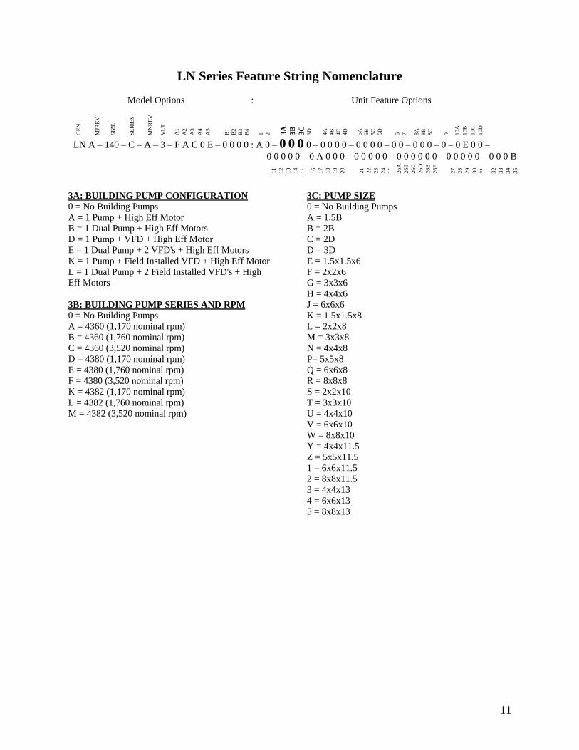
11
LN Series Feature String Nomenclature
Model Options Unit Feature Options
GE
N
MJR
EV
S
IZE
SE
RIE
S
MN
RE
V
VL
T
A1
A2
A3
A4
A5
B1
B2
B3
B4
1
2 3A
3B
3C
3D
4A
4B
4C
4D
5A
5B
5C
5D
6
7
8A
8B
8C
9
10A
10B
10C
10D
LN A ndash 140 ndash C ndash A ndash 3 ndash F A C 0 E ndash 0 0 0 0 A 0 ndash 0 0 0 0 ndash 0 0 0 0 ndash 0 0 0 0 ndash 0 0 ndash 0 0 0 ndash 0 ndash 0 E 0 0 ndash
0 0 0 0 0 ndash 0 A 0 0 0 ndash 0 0 0 0 0 ndash 0 0 0 0 0 0 ndash 0 0 0 0 0 ndash 0 0 0 B
11
12
13
14
15
16
17
18
19
20
21
22
23
24
25
26A
26B
26C
26D
26E
26F
27
28
29
30
31
32
33
34
35
3A BUILDING PUMP CONFIGURATION
0 = No Building Pumps
A = 1 Pump + High Eff Motor
B = 1 Dual Pump + High Eff Motors
D = 1 Pump + VFD + High Eff Motor
E = 1 Dual Pump + 2 VFDs + High Eff Motors
K = 1 Pump + Field Installed VFD + High Eff Motor
L = 1 Dual Pump + 2 Field Installed VFDs + High
Eff Motors
3B BUILDING PUMP SERIES AND RPM
0 = No Building Pumps
A = 4360 (1170 nominal rpm)
B = 4360 (1760 nominal rpm)
C = 4360 (3520 nominal rpm)
D = 4380 (1170 nominal rpm)
E = 4380 (1760 nominal rpm)
F = 4380 (3520 nominal rpm)
K = 4382 (1170 nominal rpm)
L = 4382 (1760 nominal rpm)
M = 4382 (3520 nominal rpm)
3C PUMP SIZE
0 = No Building Pumps
A = 15B
B = 2B
C = 2D
D = 3D
E = 15x15x6
F = 2x2x6
G = 3x3x6
H = 4x4x6
J = 6x6x6
K = 15x15x8
L = 2x2x8
M = 3x3x8
N = 4x4x8
P= 5x5x8
Q = 6x6x8
R = 8x8x8
S = 2x2x10
T = 3x3x10
U = 4x4x10
V = 6x6x10
W = 8x8x10
Y = 4x4x115
Z = 5x5x115
1 = 6x6x115
2 = 8x8x115
3 = 4x4x13
4 = 6x6x13
5 = 8x8x13
12
LN Series Feature String Nomenclature
GE
N
MJR
EV
S
IZE
SE
RIE
S
MN
RE
V
VL
T
A1
A2
A3
A4
A5
B1
B2
B3
B4
1
2
3A
3B
3C
3D
4
A
4B
4C
4D
5A
5B
5C
5D
6
7
8A
8B
8C
9
1
0A
10
B
10
C
10D
LN A ndash 140 ndash C ndash A ndash 3 ndash F A C 0 E ndash 0 0 0 0 A 0 ndash 0 0 0 0 ndash 0 0 0 0 ndash 0 0 0 0 ndash 0 0 ndash 0 0 0 ndash 0 ndash 0 E 0 0 -
0 0 0 0 0 ndash 0 A 0 0 0 ndash 0 0 0 0 0 ndash 0 0 0 0 0 0 ndash 0 0 0 0 0 ndash 0 0 0 B
11
12
13
14
15
16
17
18
19
20
21
22
23
24
25
26A
26B
26C
26D
26E
26F
27
28
29
30
31
32
33
34
35
3D BUILDING PUMP MOTOR SIZE
0 = No Building Pumps
C = 1 hp
E = 2 hp
F = 3 hp
G = 5 hp
H = 75 hp
J = 10 hp
K = 15 hp
L = 20 hp
M = 25 hp
N = 30 hp
P = 40 hp
Q = 50 hp
4A BLANK
0 = Standard
4B BLANK
0 = Standard
4C BLANK
0 = Standard
4D BLANK
0 = Standard
5A BLANK
0 = Standard
5B BLANK
0 = Standard
5C BLANK
0 = Standard
5D BLANK
0 = Standard
6 REFRIGERATION OPTIONS
0 = Standard
A = Hot Gas Bypass on Non-Variable Capacity
Circuits
B = Hot Gas Bypass - All Circuits
7 REFRIGERATION ACCESSORIES
0 = Standard
A = Sight Glass
B = Compressor Isolation Valves
C = Option A + B
8A UNIT DISCONNECT TYPE
0 = Standard Single Point Power Block
A = Single Point Power Non-fused Disconnect
8B DISCONNECT SIZE
0 = Power Block
N = 100 amps
R = 150 amps
U = 225 amps
V = 250 amps
Z = 400 amps
3 = 600 amps
5 = 800 amps
7 = 1200 amps
8C BLANK
0 = Standard
9 ACCESSORIES
0 = Standard
B = Phase amp Brown Out Protection
10A UNIT CONTROL SEQUENCE
0 = Standard Controls
10B UNIT CONTROL SUPPLIER
E = MCS Controls
10C CONTROL SUPPLIER OPTIONS
0 = Standard
A = Touchscreen Interface
C = Modem
G = Option A + C
Model Options Unit Feature Options
13
LN Series Feature String Nomenclature
Model Options Unit Feature Options
GE
N
MJR
EV
S
IZE
SE
RIE
S
MN
RE
V
VL
T
A1
A2
A3
A4
A5
B1
B2
B3
B4
1
2
3A
3B
3C
3D
4A
4B
4C
4D
5A
5B
5C
5D
6
7
8A
8B
8C
9
10A
10B
10C
10
D
LN A ndash 140 ndash C ndash A ndash 3 ndash F A C 0 E ndash 0 0 0 0 A 0 ndash 0 0 0 0 ndash 0 0 0 0 ndash 0 0 0 0 ndash 0 0 ndash 0 0 0 ndash 0 ndash 0 E 0 0 ndash
0 0 0 0 0 ndash 0 A 0 0 0 ndash 0 0 0 0 0 ndash 0 0 0 0 0 0 ndash 0 0 0 0 0 ndash 0 0 0 B
11
12
13
14
15
16
17
18
19
20
21
22
23
24
25
26
A
26
B
26
C
26D
26E
26F
27
28
29
30
31
32
33
34
35
10D BMS CONNECTION amp DIAGNOSTICS
0 = None
A = BACnet IP
B = BACnet MSTP
C = Modbus IP
D = Modbus RTU
E = Lontalk
H = No BMS Connection with Diagnostics
J = BACnet IP with Diagnostics
K = BACnet MSTP with Diagnostics
L = Modbus IP with Diagnostics
M = Modbus RTU with Diagnostics
N = Lontalk with Diagnostics
11 BLANK
0 = Standard
12 VESTIBULE ACCESSORIES
0 = Standard
C = Vestibule Heating (Electric)
13 MAINTENANCE ACCESSORIES
0 = Standard
A = 115VAC Convenience Outlet Factory Wired
B = 115VAC Convenience Outlet Field Wired
C = Service Lights
F = Options A + C
J = Options B + C
14 BLANK
0 = Standard
15 CODE OPTIONS
0 = Standard ETL USA Listing
A = Chicago Code
B = ETL USA + Canada Listing
16 SHIPPING SPLITS
0 = One Piece Unit
17 AIR-COOLED CHILLER ACCESSORIES
H = Cond Coil Guards + Three Phase Cond Fan
Motor + Fan Cycling- 35degF Low Ambient
J = Cond Coil Guards + VFD Cond Fan Head
Pressure Control - 0degF Low Ambient
18 BLANK
0 = Standard
19 BLANK
0 = Standard
20 BLANK
0 = Standard
21 BLANK
0 = Standard
22 BLANK
0 = Standard
23 BLANK
0 = Standard
24 CHILLER ACCESSORIES 1
0 = Standard
A = Glycol Chiller
C = Thermometers amp Pressure Gauges
G = Option A + C
25 BLANK
0 = Standard
26A BLANK
0 = Standard
26B BLANK
0 = Standard
26C BLANK
0 = Standard
14
LN Series Feature String Nomenclature
Model Options Unit Feature Options
GE
N
MJR
EV
S
IZE
SE
RIE
S
MN
RE
V
VL
T
A1
A2
A3
A4
A5
B1
B2
B3
B4
1
2
3A
3B
3C
3D
4A
4B
4C
4D
5A
5B
5C
5D
6
7
8A
8B
8C
9
10A
10B
10C
10D
LN A ndash 140 ndash C ndash A ndash 3 ndash F A C 0 E ndash 0 0 0 0 A 0 ndash 0 0 0 0 ndash 0 0 0 0 ndash 0 0 0 0 ndash 0 0 ndash 0 0 0 ndash 0 ndash 0 E 0 0 ndash
0 0 0 0 0 ndash 0 A 0 0 0 ndash 0 0 0 0 0 ndash 0 0 0 0 0 0 ndash 0 0 0 0 0 ndash 0 0 0 B
11
12
13
14
15
16
17
18
19
20
21
22
23
24
25
26A
26B
26C
26
D
26
E
26
F
27
28
29
30
31
3
2
33
34
35
26D BLANK
0 = Standard
26E BLANK
0 = Standard
26F BLANK
0 = Standard
27 BLANK
0 = Standard
28 BLANK
0 = Standard
29 BLANK
0 = Standard
30 BLANK
0 = Standard
31 BLANK
0 = Standard
32 BLANK
0 = Standard
33 WARRANTY
0 = Standard Warranty
D = Compressor Warranty Years 2-5
34 CABINET MATERIAL
0 = Standard - Double Wall + R-13 Foam Insulation
35 PAINT amp SPECIAL PRICING
AUTHORIZATIONS
B = Premium AAON Gray Paint Exterior
E = Premium AAON Gray Paint Exterior + Shrink
Wrap
X = Special Pricing Authorization + Premium AAON
Gray Paint Exterior
1 = SPA + Premium AAON Gray Paint Exterior +
Shrink Wrap
4 = Special Pricing Authorization + Special Exterior
Paint Color
7 = SPA + Special Exterior Paint Color + Shrink
Wrap
15
General Information
AAON LN Series chillers are complete self-
contained liquid chilling units They are
assembled wired charged and run-tested
Models are available for air-cooled
applications Chiller primary pumping
packages are available as optional features
Codes and Ordinances
LN Series units have been tested and
certified by ETL in accordance with UL
Safety Standard 1995CSA C222 No 236
System should be sized in accordance with
the American Society of Heating
Refrigeration and Air Conditioning
Engineers Handbook
Installation of LN Series units must conform
to the ICC standards of the International
Mechanical Code the International Building
Code and local building plumbing and
waste water codes All appliances must be
electrically grounded in accordance with
local codes or in the absence of local codes
the current National Electric Code
ANSINFPA 70 or the current Canadian
Electrical Code CSA C221
Receiving Unit
When received the unit should be checked
for damage that might have occurred in
transit If damage is found it should be noted
on the carrierrsquos Freight Bill A request for
inspection by carrierrsquos agent should be made
in writing at once Nameplate should be
checked to ensure the correct model sizes and
voltages have been received to match the job
requirements
If repairs must be made to damaged goods
then the factory should be notified before any
repair action is taken in order to protect the
warranty Certain equipment alteration
repair and manipulation of equipment
without the manufacturerrsquos consent may void
the product warranty Contact AAON
Technical Support for assistance with
Improper installation adjustment alteration service or maintenance can cause property damage personal injury or loss of life Startup and service must be performed by a Factory Trained Service Technician
WARNING
The Clean Air Act of 1990 bans the intentional venting of refrigerant as of July 1 1992 Approved methods of recovery recycling or reclaiming must be followed
CAUTION
Coils and sheet metal surfaces present sharp edges and care must be taken when working with equipment
Failure to observe the following instructions will result in premature failure of your system and possible voiding of the warranty
WARNING
WARNING
16
handling damaged goods repairs and freight
claims (918) 382-6450
Storage
If installation will not occur immediately
following delivery store equipment in a dry
protected area away from construction traffic
and in the proper orientation as marked on the
packaging with all internal packaging in
place Secure all loose-shipped items
Chiller
Failure to observe the following instructions
will result in premature failure of your
system and possible voiding of the warranty
Never turn off the main power supply to the
unit except for complete shutdown When
power is cut off from the unit any
compressors using crankcase heaters cannot
prevent refrigerant migration This means the
compressor will cool down and liquid
refrigerant may accumulate in the
compressor The compressor is designed to
pump refrigerant gas and damage may occur
when power is restored if liquid enters the
compressor
Before unit operation the main power switch
must be turned on for at least 24 hours for
units with compressor crankcase heaters
This will give the crankcase heater time to
clear any liquid accumulation out of the
compressor before it is required to run
Rotation must be checked on all MOTORS AND COMPRESSORS of three phase units All motors to include and not be limited to pump motors and condenser fan motors should all be checked by a qualified service technician at startup and any wiring alteration should only be made at the unit power connection
CAUTION
Scroll compressors are directional and will be damaged by operation in the wrong direction Low pressure switches on compressors have been disconnected after factory testing Rotation should be checked by a qualified service technician at startup using suction and discharge pressure gauges and any wiring alteration should only be made at the unit power connection
CAUTION
CRANKCASE HEATER OPERATION
Units may be equipped with compressor crankcase heaters which should be energized at least 24 hours prior to cooling operation to clear any liquid refrigerant from the compressors
CAUTION
COMPRESSOR CYCLING
3 MINUTE MINIMUM OFF TIME To prevent motor overheating compressors must cycle off for a minimum of 3 minutes
3 MINUTE MINIMUM ON TIME To maintain the proper oil level compressors must cycle on for a minimum of 3 minutes The cycle rate must not exceed 6 starts per hour
WARNING
17
Never cut off the main power supply to the
unit except for complete shutdown Always
control the system from the building
management system or control panel never
at the main power supply (except for
emergency or for complete shutdown of the
system)
Scroll compressors must be on a minimum of
3 minutes and off for a minimum of 3
minutes The cycle rate must be no more than
6 starts per hour
The chiller is furnished with a pressure
differential switch that is factory installed
between the chilled water supply and return
connections This sensor must not be
bypassed since it provides a signal to the unit
controller that water flow is present in the
heat exchanger and the unit can operate
without the danger of freezing the liquid
Compressor life will be seriously shortened
by reduced lubrication and the pumping of
excessive amounts of liquid oil and liquid
refrigerant
Wiring Diagrams
A complete set of unit specific wiring
diagrams in both ladder and point-to-point
form are laminated in plastic and located
inside the control compartment door
General Maintenance
When the initial startup is made and on a
periodic schedule during operation it is
necessary to perform routine service checks
on the performance of the chiller This
includes reading and recording suction
pressures and checking for normal sub-
cooling and superheat See the air-cooled
condenser sections in this manual for specific
details
Chiller Primary Pumping
Primary pumping uses a single pump to move
water (or glycol) through the chiller barrel
and back to the building This pumping
package provides a constant or variable flow
of water to the system The pump is activated
whenever the chiller is given a run signal
Water enters the unit through the return water
piping and then travels through an air
separator to remove any air that is entrapped
in the water Following this the water flows
through a suction guide with strainer The
end of the suction guide is removable for
strainer access The strainer assembly is
composed of two parts the operational
strainer and the startup strainer (located
inside the operational strainer) which is to be
removed 24 hours after startup
The pump is installed after the suction guide
and before a combination valve (Flo-Trex)
This combination valve acts as isolation
valve check valve and flow balancing valve
The shell and tube or brazed plate evaporator
is placed after the combination valve in the
water circuit with a flow switch installed
across its inlet and outlet This flow switch
closes when the velocity is above 07 feet per
second The closing flow switch signals the
control system to indicate flow through the
heat exchanger and allow cooling to activate
as required to maintain the setpoint The
water exiting the chiller evaporator leaves the
unit through the water out connection
18
Automatic Air Vent
There is an automatic air vent installed at the
high point of the system inside the pumping
package compartment The air vent valve
must be in the proper position for operation
Ensure that the small vent cap is loosened two
turns from the closed position allowing air to
be vented from the system It is advisable to
leave the cap on to prevent impurities from
entering the valve See appendix for
additional information
Dual Pumps
When redundant pumping is required factory
installed dual pumps can be ordered A dual
pump is a pump with two independent motors
and pumps in a single casing This dual pump
has a swing split-flapper valve in the
discharge port to prevent liquid recirculation
when only one pump is operating Isolation
valves in the casing allow one pump to be
isolated and removed for service while the
other pump is still operating
The controls package will activate the pump
when the unit is given a run command If the
controls do not recognize flow in 60 seconds
the second pump will be activated and an
alarm signal will be generated If the second
pump does not activate the cooling will be
locked out See appendix for additional
information
Pressure Gauges and Thermometers
Pressure gauges and thermometers are
available as a factory installed option
Thermometers are installed on the inlet and
outlet of the unit One pressure gauge is
installed at each pump This pressure gauge
is connected in three places to the water
piping before the suction guidestrainer after
the suction guide and before the pump and
after the pump There is also a needle valve
at each of these points to isolate the pressure
To measure the pressure at any given point
open the needle valve at that point and close
the other two needle valves One gauge is
used so that the calibration of the pressure
gauge is irrelevant in the calculation of the
differential pressure
Pipe Insulation
The water piping and components on units
with pumping packages are not insulated at
the factory Insulation should be installed on
the water piping after the system has been
checked for leaks
19
Installation
Chiller Placement
The AAON LN Series is designed for
outdoor applications and mounting at ground
level or on a rooftop It must be placed on a
level and solid foundation that has been
prepared to support its weight
The placement relative to the building air
intakes and other structures must be carefully
selected Be sure to observe the dimensions
that are on the rating plate of the chiller for
operational and service clearances
Table 1 - Service Clearances
Location Unit Size
45-140 tons
Front -
(Controls Side) 72rdquo
Back 72rdquo
Ends 96rdquo
Top Unobstructed
Condenser coils and fans must be free of any
obstructions in order to start and operate
properly with a correct amount of airflow
For proper unit operation the immediate area
around condenser must remain free of debris
that may be drawn in and obstruct airflow in
the condensing section
Consideration must be given to obstruction
caused by snow accumulation when placing
the unit
Curb and Steel Mount Installation
Make openings in the roof decking large
enough to allow for water piping electrical
penetrations and workspace only Do not
make openings larger than necessary Set the
curb to coincide with the openings Make
sure curb is level
If the LN is installed on a curb use a curb cap
for the open area under the condenser section
Unit specific curb drawing is included with
job submittal See SMACNA Architectural
Sheet Metal Manual for curb installation
details
Units require rail support along all four sides
of the unit base
When installed at ground level a one-piece
concrete slab should be used with footings
that extend below the frost line Care must
also be taken to protect the coil and fins from
damage due to vandalism or other causes
If unit is elevated a field supplied catwalk is
recommended to allow access to unit service
doors
This unit ships with a curb gasket that is 1frac14rdquo
wide and 1frac12rdquo tall It is recommended that this
or another similar gasket be used between the
curb and the unit to reduce vibration from the
unit to the building
All roofing work should be performed by competent roofing contractors to avoid any possible leakage
CAUTION
Figure 1 - LN Base
20
Figure 2 - Curb Mounting with Dimensions
Figure 3 - Steel Mounting Rail with
Dimensions
Table 2 - Mounting Dimensions
Tons A B C D
45-140 142rdquo 138rdquo 134rdquo 139rdquo
Figure 2
Figure 3
Lifting and Handling
If cables or chains are used to hoist the unit
they must be the same length and care should
be taken to prevent damage to the cabinet
See Figure 5 and Figure 6 for additional
information
Before lifting unit be sure that all shipping
material has been removed from unit Secure
hooks and cables at all lifting points lugs
provided on the unit
Hoist unit to a point directly above the curb
or mounting rail Be sure that the gasket
material has been applied to the curb or
mounting rail
Carefully lower and align unit with utility and
duct openings Lower the unit until the unit
skirt fits around the curb Make sure the unit
is properly seated on the curb and is level
Figure 4 - Lifting Points
21
Figure 5 - Lifting Detail of a 45-60 ton Unit
Figure 6 - Lifting Detail of a 75-140 ton Unit
Lifting slot locations are unit specific
Unit must be rigged at all marked lifting points
22
Water Connection
Connect the supply and return water lines
The connection size is listed on the unit rating
sheet along with the designed volumetric
flow rate The maximum operating pressure
for AAON LN Series units is 125 psi
Mounting Isolation
For roof mounted applications or anytime
vibration transmission is a factor vibration
isolators may be used
Access Doors
Lockable access door is provided to the
compressor and control compartment A
separate access door is also provided to the
pumping package compartment
A light switch with service lights is provided
on the wall of the compressor and control
compartment
End Flashing Installation
On all LN Series units the cabinet width will
overhang the shipping trailer on each side
In order to secure and protect the unit during
transit the sheet metal end flashings have
been removed from the unit The slot created
at the base of each end of the unit allows the
unit to set firmly on the trailer deck
Sheet metal flashings are shipped loose with
the unit and once the unit is set into place the
flashings must be installed on each end of the
unit to complete the finished seal at the base
The flashings are unit specific and designed
to cover the slot at each end of the unit to
prevent water run-off into the curb
Failure to attach and seal the end of unit with
the flashings may result in water leakage into
the curb
Figure 7 - Factory Supplied End Flashings
PVC (Polyvinyl Chloride) and CPVC (Chlorinated Polyvinyl Chloride) are vulnerable to attack by certain chemicals Polyolester (POE) oils used with R-410A and other refrigerants even in trace amounts in a PVC or CPVC piping system will result in stress cracking of the piping and fittings and complete piping system failure
CAUTION
The chiller must be operated only with liquid flowing through the evaporators
WARNING
Installing Contractor is responsible for proper sealing of the water piping entries into the unit Failure to seal the entries may result in damage to the unit and property
CAUTION
23
Low Ambient Operation
If the chiller is ordered for a Low Ambient
application the liquid system must use a
glycol solution and the piping must be
insulated to be prepared for freezing
conditions Care must be taken in the source
of electrical power for the heating tape and
thermostat
Electrical
The single point electrical power connections
are made in the electrical control
compartment
The microprocessor control furnished with
the unit is supplied with its own power supply
factory wired to the main power of the
outdoor mechanical room
Verify the unit nameplate voltage agrees with
the power supply Connect power and control
field wiring as shown on the unit specific
wiring diagram provided with the unit
Size supply conductors based on the unit
MCA rating Supply conductors must be
rated a minimum of 167degF (75degC)
Route power and control wiring separately
through the utility entry Do not run power
and signal wires in the same conduit
Protect the branch circuit in accordance with
code requirements The unit must be
electrically grounded in accordance with
local codes or in the absence of local codes
the current National Electric Code
ANSINFPA 70 or the current Canadian
Electrical Code CSA C221
Power wiring is to the unit terminal block or
main disconnect All wiring beyond this point
has been done by the manufacturer and
cannot be modified without effecting the
units agencysafety certification
Figure 8 - Front View of Utility Entry and
Power Switch from Control Compartment
Electric shock hazard Before attempting to perform any installation service or maintenance shut off all electrical power to the unit at the disconnect switches Unit may have multiple power supplies Failure to disconnect power could result in dangerous operation serious injury death or property damage
WARNING
In order to prevent water leakage into the roof curb the factory provided sheet metal flashings MUST BE attached to the unit base to cover the shipping slots at both ends of the unit
CAUTION
24
Startup technician must check for proper
motor rotation and check fan motor amperage
listed on the motor nameplate is not
exceeded Motor overload protection may be
a function of the variable frequency drive and
must not be bypassed
Note All units are factory wired for
208230V 460V or 575V If unit is to be
connected to a 208V supply the transformer
must be rewired to 208V service For 208V
service interchange the yellow and red
conductor on the low voltage control
transformer
Red-Black for 208V
Yellow-Black for 230V
Wire control signals to the unitrsquos low voltage
terminal block located in the controls
compartment All wiring beyond this point
has been completed by the manufacturer and
cannot be modified without effecting the
unitrsquos agencysafety certification
If any factory installed wiring must be
replaced use a minimum 221degF (105degC) type
AWM insulated conductors
Supply voltage must be within the minmax
range shown on the unit nameplate Available
short circuit current should not exceed the
short circuit current rating (SCCR) shown on
the unit nameplate
Three phase voltage imbalance will cause
motor overheating and premature failure
The maximum allowable imbalance is 5
Voltage imbalance is defined as 100 times the
maximum deviation from the average voltage
divided by the average voltage
Example
(218V+237V+235V)3 = 230V then
100(230V-218V)230V = 52 which
exceeds the allowable imbalance
Check voltage imbalance at the unit
disconnect switch and at the compressor
terminal Contact your local power company
for line voltage corrections
Three phase voltage imbalance will cause motor overheating and premature failure
CAUTION
Scroll compressors are directional and will be damaged by operation in the wrong direction Low pressure switches on compressors have been disconnected after factory testing Rotation should be checked by a qualified service technician at startup using suction and discharge pressure gauges and any wiring alteration should only be made at the unit power connection
Installing Contractor is responsible for proper sealing of the electrical and gas entries into the unit Failure to seal the entries may result in damage to the unit and property
CAUTION CAUTION
25
Variable Speed Compressors
Variable speed compressors should not be
operated outside the factory determined
frequency range The factory determined
compressor VFD frequency range is given
below in Table 3
Table 3- Tandem Circuited Variable Speed
Compressor VFD Frequency Range
Model (LN-) Compressor VFD
Range (Hz)
208V 230V 460V and 575V Units
045 055 060 45-65Hz
075 45-70Hz
095 105 120 35-60 Hz
140 35-65 Hz
No variable speed compressor shall operate below 35 Hz Operating variable speed compressors outside the frequency range specified in this manual voids all warranties and may result in compressor failure
CAUTION
Rotation must be checked on all MOTORS AND COMPRESSORS of three phase units Condenser fan motors should all be checked by a qualified service technician at startup and any wiring alteration should only be made at the unit power connection Variable frequency drives are programmed to automatically rotate the fan in the correct rotation Do not rely on fans with variable frequency drives for compressor rotation
CAUTION
26
Startup (See back of the manual for startup form)
Before the startup of the chiller be sure that
the following items have been checked
1 Verify that electrical power is available to
the unit
2 Verify that any remote stopstart device
connected to the chiller controller is
requesting the chiller to start
3 Verify that liquid flow is present through
the chiller from the building
4 There should be a building load of at least
25 of the chiller capacity in order to
properly check operation
5 With the main power switch off review
the MCS Controller Manual provided
with the chiller Understand the keypad
functions how to set the leaving water
temperature setpoint and how to initiate
the Run State
Use the general check list at the top of the
startup form to make a last check that all the
components are in place water flow is
present and the power supply is energized
Using the controller keypad individually set
the outputs in ldquoManual Onrdquo to confirm relay
closure and compressor operation
Cycle through all the compressors to confirm
that all are operating within tolerance
While performing the check use the startup
form to record observations of compressor
amps and refrigerant pressures
When all is running properly place the
controller in the Run mode and observe the
system until it reaches a steady state of
operation
Note For more information on programming
the controller refer to the MCS Controller
manual provided with the chiller
Electric shock hazard Shut off all electrical power to the unit to avoid shock hazard or injury from rotating parts
WARNING
Improper installation adjustment alteration service or maintenance can cause property damage personal injury or loss of life Startup and service must be performed by a Factory Trained Service Technician
WARNING
Rotation must be checked on all MOTORS AND COMPRESSORS of three phase units All motors to include and not be limited to pump motors and condenser fan motors should all be checked by a qualified service technician at startup and any wiring alteration should only be made at the unit power connection
CAUTION
Before completing installation a complete operating cycle should be observed to verify that all components are functioning properly
CAUTION
27
Axial Flow Condenser Fans
Multi-Wing Z Series Aluminum Fan Blade
Pitch Angle Setting Instructions
1 Maintain the balance of fan
Mark the hub castings across a joint so the
fan hub can be reassembled in the same
orientation
Mark the location of any balancing weight
Balancing weight will be on the outer bolt
circle in the form of washers andor longer
bolts or an additional balancing nut
Number the blades and blade sockets so that
they are replaced into their original position
Figure 9 - Fan with the HUB on the top and
RET on the bottom
2 Determine the direction of rotation
Right R is clockwise when facing the
discharge side of the fan and Left L is
counterclockwise when facing the discharge
side of the fan
3 Determine the bushing mount location
The bushing mount is the center section of the
hub through which the fan is mounted to the
shaft and typically contains either setscrews
or a center-tapered hole where the bushing
inserts
Location A is with the bushing mount on air
inlet side of the fan
Location B is with the bushing mount on air
discharge side of the fan
Figure 10 - Bushing Mount Location
4 Determine the pin location groove
Disassemble fan on a flat surface and note in
which groove the pin is located
Figure 11 - RET with Pin in Groove 4
Bushing
Mount
A B Bushing
Mount
Bushing Bushing
1 2 3 4
28
5 Determine whether the pin is in the HUB
or RET
Figure 12 - Fan HUB and RET Castings
6 Determine the current blade pitch and the pin location for the new blades
Table 4 - ReturnExhaust Fan Pin Location
Type Bushing
Mount
Blade Pitch Angle
20deg 25deg 28deg 30deg 33deg 35deg 38deg 40deg 45deg 50deg
5Z A - RET - RET RET RET HUB HUB HUB HUB
B - HUB - HUB HUB HUB RET RET RET RET
Table 5 - ReturnExhaust Fan Pin Location
Type Rot Blade Pitch Angle
20deg 25deg 28deg 30deg 33deg 35deg 38deg 40deg 45deg 50deg
5Z R - 4 - 3 2 1 4 3 2 1
L - 1 - 2 3 4 1 2 3 4
7 Replace fan blades in the new pin
location and reassemble the fan
Replace the blades with the pin in the 1 2 3
or 4 groove position of either the HUB or
RET Assemble the fan making sure to place
the blades in their previous blade sockets to
match up the previous orientation of HUB
and RET and to replace any balancing
weights in their previous locations Tighten
bolts in a cross pattern to 5-6 ft-lbs of torque
29
Multi-Wing W Series Black Glass
Reinforced Polypropylene Fan Blade Pitch
Angle Setting Instructions
Contact the AAON parts department to
acquire the new pitch pins for the fan blades
Note original position of retaining plates
center boss and all hardware including
additional hardware used for balancing
1 Remove all the bolts and nuts
2 Determine blade rotation ndash on the concave
side of the blade is a blade marking showing
6WR 6WL 7WL 7WR or 9WR The ldquoLrdquo
and ldquoRrdquo denote the rotation of the blade
3 Replace the pitch insert in the blade root
with an insert of the desired pitch
Figure 13 - Pitch Insert
4 Replace blades to their original location
5 Replace all nuts bolts and washers on the
fan hub
6 Replace retaining plates and center boss to
original location
7 Tighten nuts and bolts to 14 ft-lbs of
torque
Fan Assembly Bushings
The fan assembly bushings should be
tightened to the specifications listed in the
following table
Table 6 - Fan Assembly Bushing Torque
Specifications
Bushing Tightening Torque
(in-lbs)
H X 1125 95
H X 1375 95
SH X 1125 108
SH X 1375 108
SD X 1125 108
SD X 1375 108
SD X 1625 108
SD X 1875 108
SK X 2125 180
30
Maintenance
General
Qualified technicians must perform routine
service checks and maintenance This
includes reading and recording the
condensing and suction pressures and
checking for normal sub-cooling and
superheat
Air-cooled chillers require maintenance
schedulesprocedures Unit specific
instructions are included in this manual
Compressors
The scroll compressors are fully hermetic and
require no maintenance except keeping the
shell clean
Refrigerant Suction Line Filter
Each refrigerant circuit contains a
replaceable core suction line filter One
month after start-up remove the filter
element
The replaceable core suction filters are
provided with pressure taps and shutoff
valves for isolation when removing the filter
For safety purposes a service manifold must
be attached prior to filter maintenance
Suction Filter Removal Instructions
1 Shut down operation of the unit
2 Close both shut-off valves to isolate
the suction filter
3 Reclaim the refrigerant from the
suction filter section
4 Remove the bolts from the suction
filter end plate
5 Remove the pleated filter assembly
Prior to filter core service a service manifold MUST BE attached to in and out pressure connections to assure no pressure exists during filter maintenance Non-compliance could result in injury or violation of EPA regulations
Service gauges MUST BE connected before operating the isolation valves for the replaceable core filter
WARNING
WARNING
31
6 Replace the suction filter end plate
and bolts
7 Evacuate the suction filter assembly
to 500 microns
8 Open both shut-off valves
Adjusting Refrigerant Charge
All AAON chillers are shipped with a full
factory charge Periodically adjusting the
charge of a system may be required
Adjusting the charge of a system in the field
must be based on determination of liquid sub-
cooling and evaporator superheat On a
system with an expansion valve liquid sub-
cooling is more representative of the charge
than evaporator superheat but both
measurements must be taken
Before Charging
Refer to the unit nameplate as a reference
when determining the proper refrigerant
charge
Unit being charged must be at or near full
load conditions before adjusting the charge
Units equipped with hot gas bypass must
have the hot gas bypass valve closed to get
the proper charge
After adding or removing charge the system
must be allowed to stabilize typically 10-15
minutes before making any other
adjustments
The type of unit and options determine the
ranges for liquid sub-cooling and evaporator
superheat Refer to Table 7 when determining
the proper sub-cooling
For units equipped with low ambient (0degF)
option see the special charging instructions at
the end of this section
Checking Liquid Sub-cooling
Measure the temperature of the liquid line as
it leaves the condenser coil
Read the gauge pressure at the liquid line
close to the point where the temperature was
taken You must use liquid line pressure as it
will vary from discharge pressure due to
condenser coil pressure drop
Convert the pressure obtained to a saturated
temperature using the appropriate refrigerant
temperature-pressure chart
Subtract the measured liquid line temperature
from the saturated temperature to determine
the liquid sub-cooling
Compare calculated sub-cooling to the table
below for the appropriate unit type and
options
The Clean Air Act of 1990 bans the intentional venting of refrigerant (CFCrsquos and HCFCrsquos) as of July 1 1992 Approved methods of recovery recycling or reclaiming must be followed Fines andor incarceration may be levied for non-compliance
CAUTION
Polyolester (POE) and Polyvinylether (PVE) oils are two types of lubricants used in hydrofluorocarbon (HFC) refrigeration systems Refer to the compressor label for the proper compressor lubricant type
CAUTION
32
Checking Evaporator Superheat
Measure the temperature of the suction line
close to the compressor
Read gauge pressure at the suction line close
to the compressor
Convert the pressure obtained to a saturated
temperature using the appropriate refrigerant
temperature-pressure chart
Subtract the saturated temperature from the
measured suction line temperature to
determine the evaporator superheat
For refrigeration systems with tandem scroll
compressors it is critical that the suction
superheat setpoint on the expansion valve is
set with one compressor running The suction
superheat should be 10-13degF with one
compressor running The suction superheat
will increase with both compressors in a
tandem running Inadequate suction
superheat can allow liquid refrigerant to
return to the compressors which will wash the
oil out of the compressor Lack of oil
lubrication will destroy a compressor Liquid
sub-cooling should be measured with both
compressors in a refrigeration system
running
Compare calculated superheat to Table 7 for
the appropriate unit type and options
Table 7 - Acceptable Refrigeration Circuit
Values
Air-Cooled Chiller with Scroll
Compressors
Sub-Cooling2 12-18degF
Superheat1 10-15degF 1 One compressor running in tandem 2 Two compressors running in tandem
Adjusting Sub-cooling and Superheat
Temperatures
The system is overcharged if the sub-cooling
temperature is too high and the evaporator is
fully loaded (low loads on the evaporator
result in increased sub-cooling) and the
evaporator superheat is within the
temperature range as shown in Table 7 (high
superheat results in increased sub-cooling)
Correct an overcharged system by reducing
the amount of refrigerant in the system to
lower the sub-cooling
The system is undercharged if the superheat
is too high and the sub-cooling is too low
Correct an undercharged system by adding
refrigerant to the system to reduce superheat
and raise sub-cooling
If the sub-cooling is correct and the superheat
is too high the expansion valve may need
adjustment to correct the superheat
Expansion valves must be adjusted to approximately 10-15degF of suction superheat Failure to have sufficient superheat will damage the compressor and void the warranty
CAUTION
DO NOT OVERCHARGE Refrigerant overcharging leads to excess refrigerant in the condenser coils resulting in elevated compressor discharge pressure
CAUTION
33
Table 8 - R-410A Refrigerant Temperature-Pressure Chart
F psig F psig F psig F psig F psig
20 783 50 1422 80 2349 110 3641 140 5401
21 800 51 1448 81 2386 111 3691 141 5470
22 818 52 1474 82 2423 112 3742 142 5539
23 836 53 1501 83 2460 113 3794 143 5609
24 854 54 1528 84 2498 114 3846 144 5679
25 872 55 1555 85 2537 115 3899 145 5751
26 891 56 1582 86 2575 116 3952 146 5823
27 910 57 1610 87 2614 117 4005 147 5896
28 929 58 1638 88 2654 118 4059 148 5969
29 949 59 1667 89 2694 119 4114 149 6044
30 968 60 1696 90 2735 120 4169 150 6119
31 988 61 1725 91 2776 121 4225
32 1009 62 1754 92 2817 122 4282
33 1029 63 1784 93 2859 123 4339
34 1050 64 1815 94 2901 124 4396
35 1071 65 1845 95 2944 125 4454
36 1092 66 1876 96 2987 126 4513
37 1114 67 1907 97 3030 127 4573
38 1136 68 1939 98 3075 128 4632
39 1158 69 1971 99 3119 129 4693
40 1181 70 2004 100 3164 130 4754
41 1203 71 2036 101 3210 131 4816
42 1227 72 2070 102 3256 132 4878
43 1250 73 2103 103 3302 133 4941
44 1274 74 2137 104 3349 134 5005
45 1298 75 2171 105 3396 135 5069
46 1322 76 2206 106 3444 136 5134
47 1347 77 2241 107 3493 137 5200
48 1372 78 2277 108 3542 138 5266
49 1397 79 2313 109 3591 139 5333
34
Lubrication
All original motors and bearings are
furnished with an original factory charge of
lubrication Certain applications require
bearings be re-lubricated periodically The
schedule will vary depending on operating
duty temperature variations or severe
atmospheric conditions
Bearings should be re-lubricated at normal
operating temperatures but not when
running
Rotate the fan shaft by hand and add only
enough grease to purge the seals DO NOT
OVERLUBRICATE
Air-Cooled Condenser
The air-cooled condenser section rejects heat
by passing outdoor air over the fin tube coils
for cooling of the hot refrigerant gas from the
compressors The heated air will discharge
from the top of the section through the axial
flow fans
The condenser coils should be inspected
yearly to ensure unrestricted airflow If the
installation has a large amount of airborne
dust or other material the condenser coils
should be cleaned according to the
microchannel coil cleaning section
Brazed Plate Heat Exchanger Cleaning
Because of a normally high degree of
turbulence in brazed plate heat exchangers
for many applications the heat exchanger
channels are self-cleaning For applications
that are not self-cleaning (ie hard water at
high temperatures etc) or applications where
additional cleaning is desired it is possible to
clean the brazed plate heat exchanger by
circulating a cleaning liquid
Use a tank with weak acid 5 phosphoric
acid (H3PO4) or if the exchanger is
frequently cleaned 5 oxalic acid (H2C2O4)
Pump the cleaning liquid through the
exchanger For optimum cleaning the
cleaning solution flow rate should be a
minimum of 15 times the normal flow rate
preferably in a back-flush mode After
cleaning the heat exchanger must be rinsed
with clean water A solution of 1-2 sodium
hydroxide (NaOH) or sodium bicarbonate
(NaHCO) before the last rinse ensures that all
acid is neutralized
E-Coated Coil Cleaning
Documented quarterly cleaning of e-coated
coils is required to maintain coating warranty
coverage
Surface loaded fibers or dirt should be
removed prior to water rinse to prevent
restriction of airflow If unable to back wash
the side of the coil opposite of the coils
entering air side then surface loaded fibers or
dirt should be removed with a vacuum
cleaner If a vacuum cleaner is not available
a soft non-metallic bristle brush may be used
In either case the tool should be applied in
the direction of the fins Coil surfaces can be
easily damaged (fin edges bent over) if the
tool is applied across the fins
Use of a water stream such as a garden hose
against a surface loaded coil will drive the
fibers dirt and salts into the coil This will
make cleaning efforts more difficult Surface
loaded fibers must be completely removed
prior to using low velocity clean water rinse
Electric shock hazard Shut off all electrical power to the unit to avoid shock hazard or injury from rotating parts
WARNING
35
Quarterly cleaning is required to maintain
warranty coverage and is essential to
maintain the life of an E-coated coil Coil
cleaning shall be part of the units regularly
scheduled maintenance procedures
Failure to clean an E-coated coil on the
prescribed quarterly cycle will void the
warranty and may result in reduced
efficiency and durability in the environment
A routine two-step quarterly coil cleaning is
required to maintain warranty
Step one is to clean the coil with the below
approved coil cleaner (see approved products
list under the Recommended Coil Cleanersrdquo
section
Step two is to use the approved saltchloride
remover under the Recommended Chloride
Removerrdquo section to dissolve soluble salts
and revitalize the unit It is very important
when cleaning andor rinsing not to exceed
130degF and potable water pressure is less than
100 psig to avoid damaging the unit and coil
fin edges
For routine quarterly cleaning first clean the
coil with the below approved coil
cleaner After cleaning the coils with the
approved cleaning agent use the approved
chloride remover to remove soluble salts and
revitalize the unit
Recommended Coil Cleaner ndash Step 1
GulfCoatTM Coil Cleaner assuming it is
used in accordance with the manufacturers
directions on the container for proper mixing
and cleaning has been approved for use on
E-coated coils to remove mold mildew dust
soot greasy residue lint and other
particulate Never use any cleaners that are
not approved
Recommended Chloride Remover ndash Step 2
CHLORRIDreg Concentrate assuming it
is used in accordance with the manufacturers
directions on the container for proper mixing
has been approved for use on E-coated coils
to remove chloridessalts amp sulfates Never
use any chloride removers that are not
approved
Warranty Protection ndash Step 1
Complete the coil cleaning following these
steps
1 Ensure that the power to the unit is off
and locked out
2 Clean the area around the unit if
needed to ensure leaves grass or
High velocity water from a pressure washer or compressed air should only be used at a very low pressure to prevent fin andor coil damages The force of the water or air jet may bend the fin edges and increase airside pressure drop Reduced unit performance or nuisance unit shutdowns may occur
Harsh chemicals household bleach or acid cleaners should not be used to clean e-coated coils These cleaners can be very difficult to rinse out of the coil and can accelerate corrosion and attack the e-coating If there is dirt below the surface of the coil use the recommended coil cleaners
CAUTION
CAUTION
36
loose debris will not be blown into the
coil
3 Remove panels or tops as required
gaining access to the coil(s) to be
cleaned
4 Using a pump up sprayer fill to the
appropriate level with potable water
and add the correct amount of
approved cleaner as per manufacture
instructions leaving room for the
pump plunger to be reinserted
NOTE Coils should always be cleaned
back flushed opposite of airflow to prevent
impacting the dirt into the coil
5 If the coils have heavy dirt fibers
grass leaves etc on the interior or
exterior face areas a vacuum and
brush should be used to remove those
surface contaminants prior to
applying cleaner The interior floor
drain tray or pan areas should also be
vacuumed
6 Apply the mixed cleaner to coil
surfaces using a pressurized pump up
sprayer maintaining a good rate of
pressure and at a medium size nozzle
spray (not a solid stream and not a
wide fan but somewhere in the
middle) Work in sectionspanels
ensuring that all areas are covered and
kept wetted
7 Apply the cleaner to unit interior air
exiting side coil surfaces first Work
in sectionspanels moving side to side
and from top to bottom
8 Generously soak coils by spraying
cleaner directly on and into the fin
pack section to be cleaned and allow
the cleaning solution to soak for 5 to
10 minutes
9 Using pressurized potable water
(lt100 psi) rinse the coils and
continue to always work in
sectionspanels Start at the top of the
coil and slowly move vertically
downward to the bottom Then
staying in the same vertical area
slowly move back up to the top where
you started Now move over slightly
overlapping the area just completed
and repeat above Continue until all
coil areas on the inside of the unit
have been rinsed
10 Complete steps 5-9 for the exterior air
entering side of the coils
11 Final rinse ndash Now complete a quick
rinse of both sides of the coil
including the headers piping u-
bends and hairpins
12 If the coil has a drain pan or unit floor
that is holding rinse water or cleaner
extra time and attention will need to
be taken in those areas to ensure a
proper rinse has been completed
Warranty Protection ndash Step 2
Complete the coil chloride (salt) removal
following these steps
1 CHLORRIDreg is a concentrate to be
used for both normal inland
applications at a 1001 mix ratio OR
for severe coastal applications 501
mix ratio with potable water (256
ounces of Chlorrid to 1 gal of water)
Using a pump up sprayer fill to the
appropriate level with potable water
and add the correct amount of
CHLORRIDreg salt remover leaving
room for the pump plunger to be
reinserted
2 Apply CHLORRIDreg to all external
coil surfaces using a pressurized
pump up sprayer maintaining a good
rate of pressure and at a medium size
nozzle spray (not a solid stream and
not a wide fan but somewhere in the
middle) Work in sectionspanels
ensuring that all areas are covered and
kept wetted
37
3 Generously soak coils by spraying
CHLORRIDreg directly on and into
the fin pack section Let stand for 5 to
10 minutes keeping the area wetted
Do not allow to dry before rinsing
4 Using pressurized potable water
(lt100 psi) rinse the CHLORRIDreg
and dissolved chloridessalts off of
the coils continuing to always work in
sectionspanels
5 Starting at the top of the coil begin
rinsing the coil from side to side until
you reach the bottom Repeat as many
times as is necessary to ensure all coil
sectionspanels have been completed
and are thoroughly rinsed
6 Reinstall all panels and tops that were
removed
Microchannel Coil Cleaning
Documented routine cleaning of
microchannel coils with factory provided e-
coating is required to maintain coating
warranty coverage See E-Coated Coil
Cleaning section
Air-cooled heat exchangers may include
microchannel coils
Cleaning microchannel coils is necessary in
all locations In some locations it may be
necessary to clean the coils more or less often
than recommended In general a condenser
coil should be cleaned at a minimum of once
a year In locations where there is commonly
debris or a condition that causes dirtgrease
build up it may be necessary to clean the coils
more often Proper procedure should be
followed at every cleaning interval Using
improper cleaning technique or incorrect
chemicals will result in coil damage system
performance fall off and potentially leaks
requiring coil replacement
Documented routine cleaning of
microchannel coils with factory provided e-
coating is required to maintain coating
warranty coverage Use the E-Coated Coil
Cleaning section for details on cleaning e-
coated coils
Field applied coil coatings are not
recommended with microchannel coils
Allowed Chemical Cleaners and Procedures
AAON recommends certain chemicals that
can be used to remove buildup of grime and
debris on the surface of microchannel coils
These chemicals have been tested for
performance and safety and are the only
chemicals that AAON will warrant as correct
for cleaning microchannel coils
There are three procedures that are outlined
below that will clean the coils effectively
without damage to the coils Use of any other
procedure or chemical may void the warranty
to the unit where the coil is installed With
all procedures make sure the unit is off
before starting
The water pressure used to clean should not
exceed 140 psi from no closer than 6 inches
from the coils and with the water aimed
perpendicular to the coils
Electric shock hazard Shut off all electrical power to the unit to avoid shock hazard or injury from rotating parts
WARNING
WARNING
38
1 Simple Green
Simple Green is available from AAON Parts
and Supply (Part T10701) and is
biodegradable with a neutral 65 pH
Recommendation is to use it at a 4 to 1 mix
Use the following procedure
1 Rinse the coil completely with water Use
a hard spray but be careful not to bend or
damage the fins A spray that is too hard
will bend the fins Spray from the fan side
of the coil
2 With a pump sprayer filled with a mix of
4 parts water to one part Simple Green
spray the air inlet face of the coil Be sure
to cover all areas of the face of the coil
3 Allow the coil to soak for 10-15 minutes
4 Rinse the coil with water as in step one
5 Repeat as necessary
2 Vinegar
This is standard white vinegar available in
gallons from most grocery stores It has a pH
of 2-3 so it is slightly acidic Use the
following procedure
1 Rinse the coil completely with water Use
a hard spray but be careful not to bend or
damage the fins A spray that is too hard
will bend the fins Spray from the fan side
of the coil
2 Use a pump sprayer filled with vinegar
(100) Spray from the face of the coil in
the same direction as the airflow Be sure
to cover all areas of the face of the coil
3 Allow the coil to soak for 10-15 minutes
4 Rinse the coil with water as in step one
5 Repeat as necessary
3 Water Flush
This procedure can be used when the only
material to cause the coil to need cleaning is
debris from plant material that has impinged
the coil face
1 Rinse the coil completely with water Use
a hard spray but be careful not to bend or
damage the fins A spray that is too hard
will bend the fins Spray from the fan side
of the coil
2 Spray and rinse the coil from the face
Application Examples
The three procedures can be used to clean
microchannel coils They will fit with the
application depending on the area In some
areas where the springsummer has a large
cottonwood bloom 3 might work fine if the
unit is installed on an office building and no
other environmental factors apply
When a unit is installed where the sprinkler
system has water being sprayed onto the
condenser coil you might have better results
using 2 Vinegar is slightly acidic and may
help with the calcium build up from drying
water This also works well when grease is
part of the inlet air to a condenser coil
Generally the best and broadest based
procedure is 1 The grease cutting effect of
the Simple Green is good for restaurant
applications
Other Coil Cleaners
There are many cleaners on the market for
condenser coils Before using any cleaner
that is not covered in this section you must
get written approval from the AAON
warranty and service department Use of
unapproved chemicals will void the
warranty
Use pressurized clean water with pressure not to exceed 140 psi Nozzle should be 6rdquo and 80deg to 90deg from coil face Failure to do so could result in coil damage
CAUTION
39
AAON testing has determined that unless a
chemical has a neutral pH (6-8) it should not
be used
Beware of any product that claims to be a
foaming cleaner The foam that is generated
is caused by a chemical reaction to the
aluminum fin material on tube and fin coils
and with the fin tube and coating material on
microchannel coils
Microchannel coils are robust in many ways
but like any component they must be treated
correctly This includes cleaning the coils
correctly to give optimal performance over
many years
Service
If the unit will not operate correctly and a
service company is required only a company
with service technicians qualified and
experienced in both refrigerant chillers and
air conditioning are permitted to service the
systems to keep warranties in effect If
assistance is required the service technician
must contact AAON
Replacement Parts
Parts for AAON equipment may be obtained
from your local AAON representative When
ordering parts reference the unit serial
number and part number
AAON Technical Support
2424 S Yukon Ave
Tulsa OK 74107
Ph (918) 382-6450
techsupportAAONcom
wwwAAONcom
Note Before calling technician should have
model and serial number of the unit available
for the service department to help answer
questions regarding the unit
40
Appendix - Water Piping Component Information
Automatic Air Vent Valves
Automatic Air Vent Valves provide
automatic air venting for hot or cold water
distribution systems These vents purge air
that may be in the water system
The vent valve utilizes a float to actuate the
valve plug which is located at the top of the
valve Once the air is displaced and the
system pressure is sustained the valve plug
seals and prevents any water from escaping
from the system
The float vent can also operate as an anti-
vacuum device since it will permit air to enter
the system when it must be drained It can
also be installed to permit the separation and
dispersal of air while fluid is actually
circulating in the system
Overview
Body and cover are brass construction
Air vent with silicone rubber seal
Impurities do not usually affect function
as maximum float line of water is always
lower than the valve seal
Float is high temperature resistant
polyethylene
Suitable for use with glycol systems
Can be disassembled for inspection and
cleaning
Operating Range
Minimum working pressure 145psi
(10 kPa)
Maximum working pressure 150psi
(10 bars)
Temperature Range 33degF ndash 240degF
(5degC ndash 116degC)
Performance
Performance curve details the quantity of air
vented by the ldquoFloat Ventrdquo according to the
pressure in the system
Note In order to get the best results in
venting air from risers use connecting pipes
41
of at least 1frasl2 diameter between the ldquoFloat
Ventrdquo valves and installation
Installation
When the air vent valve is installed as shown
the air will not be vented while the fluid is
circulating in the system but it can vent when
the system is shut off
The figure below shows the installation of the
vent valve for the venting of air while the
fluid is circulating in the system and the
required increase in pipe size in order to
obtain proper separation of air from water
The valve should be mounted only in a
vertical position as its operation is based on
the vertical movement of the float
While the air vent valve is in operation back
off the small vent cap two turns This is the
proper operating setting which will allow air
to be vented from the system It is advisable
to leave the cap on to prevent impurities from
entering the valve
Maintenance
No maintenance is normally necessary
However if the FV-4M1 is disassembled for
inspection or cleaning it is important that
when re-assembling to ensure that the spring
loaded lever properly engages under the float
collar
42
Dimensions ndash Weights
Pumps - Installation and Operating
Instructions
Introduction
This document contains specific information
regarding the safe installation operating and
maintenance of Vertical In-Line pumps and
should be read and understood by installing
operating and maintenance personnel The
equipment supplied has been designed and
constructed to be safe and without risk to
health and safety when properly installed
operated and maintained The instructions
following must be strictly adhered to If
clarification is needed on any point please
contact Armstrong quoting the equipment
serial number
Where under normal operating conditions the
limit of 68degC155degF (Restricted Zone) for
normal touch or 80degC176degF (Unrestricted
Zone) for unintentional touch may be
experienced steps should be taken to
minimize contact or warn operatorsusers that
normal operating conditions will be
exceeded In certain cases where the
temperature of the pumped liquid exceeds the
above stated temperature levels pump casing
temperatures may exceed 100degC212degF and
not withstanding pump insulation techniques
appropriate measures must be taken to
minimize risk for operating personnel
Storage
Pumps removed from service and stored
must be properly prepared to prevent
excessive rusting Pump port protection
plates must not be removed until the pump is
ready to connect to the piping Rotate the
shaft periodically (At least monthly) to keep
No Installation of this equipment should take place unless this document has been read and understood
CAUTION
43
rotating element free and bearings fully
functional
For long term storage the pump must be
placed in a vertical position in a dry
environment Internal rusting can be
prevented by removing the plugs at the top
and bottom of the casing and drain or air blow
out all water to prevent rust buildup or the
possibility of freezing Be sure to reinstall the
plugs when the unit is made operational
Rust-proofing or packing the casing with
moisture absorbing material and covering the
flanges is acceptable When returning to
service be sure to remove the drying agent
from the pump
Handling Large VIL Units
One effective way of lifting a large pumping
unit is to place lifting hooks through the
motor lifting rings or straps around the upper
part of the motor The pump and motor unit
will free-stand on the casing ribs Remove the
coupling guard and place (2) lifting straps
through the pumpmotor pedestal one on
each side of the motor shaft and secure to the
lifting device
With the straps in place using a spacer bar if
necessary to protect the motor fan cover the
whole assembly can now be lifted securely
Note Handling transportation and
installation of this equipment should only be
undertaken by trained personnel with proper
use of lifting equipment
Remove coupling guard and place lifting
straps on each side of coupling use spacer
bar if necessary to protect motor fan cover
Vertical Inline Pump Lifting Strap
Positioning
Note All split-coupled pumps contain a
tapped hole in the motor bracket above the
discharge flange for draining the well Pipe
this drain hole to a floor drain to avoid
overflow of the cavity caused by collecting
chilled water condensate or from seal failure
Pump Piping - General
The discharge valve only is to be used to
throttle pump flow not the suction valve
Care must be taken in the suction line layout
and installation as it is usually the major
source of concern in centrifugal pump
applications
Discharge valve only is to be used to throttle pump flow
Use Caution Piping may carry high temperature fluid
CAUTION
CAUTION
44
Alignment
Alignment is unnecessary on close-coupled
pumps as there is no shaft coupling
Split-coupled units are accurately aligned at
the factory prior to being shipped and do not
need re-aligning when installed
Pump Operation
Starting Pump
Ensure that the pump turns freely by hand or
with some mechanical help such as a strap
and lever on larger pumps Ensure that all
protective guarding is securely fixed in
position
The pump must be fully primed on start up
Fill the pump casing with liquid and rotate the
shaft by hand to remove any air trapped in the
impeller On split coupled units any air
trapped in the casing as the system is filled
must be removed by the manual air vent in
the seal flush line Close-coupled units are
fitted with seal flushvent lines piped to the
pump suction area When these units operate
residual air is drawn out of the pump towards
the suction piping
lsquoBumprsquo or energize the motor momentarily
and check that the rotation corresponds with
the directional arrow on the pump casing To
reverse rotation of a three phase motor
interchange any two power leads
Start the pump with the discharge valve
closed and the suction valve open and then
gradually open the discharge valve when the
motor is at operating speed The discharge
valve may be lsquocrackedrsquo or open slightly at
start up to help eliminate trapped air
When stopping the pump Close the
discharge valve and de-energize the motor
DO NOT run the pump against a closed
discharge valve for an extended period of
time (A few minutes maximum)
Star-Delta motor starters should be fitted
with electronicmechanical interlocks that
have a timed period of no more than 40
milliseconds before switching from star
(Starting) to delta (Run) connection yet allow
the motor to reach full star (Starting) speed
before switching to delta (Run)
Should the pump be noisy or vibrate on start-
up a common reason is overstated system
head Check this by calculating the pump
operating head by deducting the suction
pressure gauge value from the discharge
gauge reading Convert the result into the
units of the pump head as stated on the pump
nameplate and compare the values Should
the actual pump operating head be
significantly less than the nameplate head
value it is typically permissible to throttle the
discharge isolation valve until the actual
operating head is equal to the nameplate
value
Any noise or vibration usually disappears
The system designer or operator should be
made aware of this soon as some adjustment
may be required to the pump impeller
diameter or drive settings if applicable to
make the pump suitable for the system as
installed
Do not run pumps with discharge valve closed or under very low flow conditions
CAUTION
Check rotation arrow prior to operating the unit
CAUTION
45
Check rotation arrow prior to operating the
unit The rotation of all Vertical In-Line units
is ldquoclockwiserdquo when viewed from the drive
end (Looking from on top of behind the
motor)
General Care
Vertical In-Line pumps are built to operate
without periodic maintenance other than
motor lubrication on larger units A
systematic inspection made at regular
intervals will ensure years of trouble-free
operation giving special attention to the
following
Keep unit clean
Keep moisture refuse dust or other loose
particles away from the pump and
ventilating openings of the motor
Avoid operating the unit in overheated
surroundings (Above 100ordmF40ordmC)
Any possibility of the unit starting while
being serviced must be eliminated
If mechanical seal environmental accessories
are installed ensure water is flowing through
the sight flow indicator and that filter
cartridges are replaced as recommended
Pump Lubrication
Lubrication is not required There are no
bearings in the pump that need external
lubrication service
Large Series split-coupled units are installed
with a shaft bushing located beneath the
impeller that is lubricated from the pump
discharge This bearing is field removable for
service on the 20x20x19 size without
disturbing the motor or other major pump
components
Motor
Follow the lubrication procedures
recommended by the motor manufacturer
Many small and medium sized motors are
permanently lubricated and need no added
lubrication Generally if there are grease
fittings evident the motor needs periodic
lubrication and if there are no grease fittings
evident no periodic lubrication is required
Check the lubrication instructions supplied
with the motor for the particular frame size
indicated on the motor nameplate
Mechanical Seal
Mechanical seals require no special attention
The mechanical seal is fitted with a flush line
The seal is flushed from discharge of the
pump casing on split-coupled pumps and is
flushedvented to the suction on close
coupled pumps
The split-coupled pump is flushed from the
pump discharge because the mechanical seal
chamber is isolated from the liquid in the
pump by a throttle bushing Because the seal
chamber is isolated seal environmental
controls such as filters and separators when
installed in the split-coupled flush line are
very effective as only the seal chamber needs
cleansing and will prolong seal life in HVAC
systems
Do not run the pump unless properly filled
with water as the mechanical seals need a
film of liquid between the faces for proper
operation
Electric shock hazard Before attempting to perform any service or maintenance on pumping unit disconnect power source to the driver LOCK IT OFF and tag with the reason
WARNING
46
Mechanical seals may lsquoweeprsquo slightly at
start-up Allow the pump to continue
operating for several hours and the
mechanical seal to lsquoseatrsquo properly prior to
calling for service personnel
System Cleanliness
Before starting the pump the system must be
thoroughly cleaned flushed and drained and
replenished with clean liquid
Welding slag and other foreign materials
ldquoStop Leakrdquo and cleaning compounds and
improper or excessive water treatment are all
detrimental to the pump internals and sealing
arrangement
Proper operation cannot be guaranteed if the
above conditions are not adhered to
Note
Particular care must be taken to check the
following before the pump is put into
operation
1 Pump primed
2 Rotation OK
3 Lubrication OK
4 Pipe work properly supported
5 Voltage supply OK
6 Overload protection OK
7 Is the system clean
8 Is the area around the pump clean
Warranty
Does not cover any damages to the
equipment resulting from failure to observe
the above precautions
Noise Levels
Estimated Pumping Unit Sound Power Level Decibels A-Weighted at 1 m (3 ft) from unit
Double Check Prior to Startup
CAUTION
47
Vibration Levels
Vertical In-Line pumps are designed to meet vibration levels set by Hydraulic Institute Standard
HI Pump Vibration 964 Standard levels are as detailed below
Dual Pump Specific Information
Dual Pump Flapper Valve Operating
Instructions
This unit is fitted with internal valves to allow
isolation of one pump for service and to
automatically prevent recirculation of the
flow when only one pump is running
Procedure for Parallel or Stand-By
Pumping
Discharge and suction valve stems should be
locked in the center position This is
indicated by both locking handles in the
vertical position and the center pin of the
locking arms (4) locked by the handles This
procedure allows the discharge flapper valves
to pivot freely and locks the suction valve
firmly in the center position
Procedure for Isolation of One Side
1 Stop the pump to be serviced
2 Close and lock the suction and discharge
valves as per instructions below
3 Ensure seal flush line interconnection
valve is closed and drain the isolated
casing
4 Service isolated pump as required
Procedure for Starting the Pump after
Servicing
1 Ensure serviced pump is fully re-
assembled including all seal flush lines
and drain plugs
2 Fill the dry casing with system fluid by
opening the seal flush line
interconnecting valve and the air vent
fitting
3 Allow the pressure to equalize in the two
casings if necessary by opening seal
flush line interconnected valve
4 Unlock the discharge valve as per
instructions below
5 Unlock the suction valve as per
instructions below
NOTE Keep hands and tools away from
locked suction valve arm as the differential
pressure may cause the arm to rotate quickly
with force when unlocked
6 Close the seal flush line interconnect
valve and restart pump
Valve Operation - Refer to following 3rdquo 4rdquo
amp 6rdquo valve illustration and the 8rdquo valve
illustration
48
Discharge Valve
This valve performs the dual function of
automatically sealing the discharge of the
inactive pump when one pump is running and
can manually be closed and locked to isolate
one pump for service
Automatic Flapper Operation
In the flapper mode the two halves of the
discharge valve are free to pivot
independently under normal operating
conditions The locking handle (3) should be
secured with the set screw (11) in the vertical
position with the center pin of the locking
arm (4) trapped by the locking handle (3)
Manual Valve Locking
The locking feature of this valve is to ensure
a positive seal (leak proof) of the discharge
port on the pump to be serviced
Note Ensure the pump to be isolated is not
operating before attempting to release the
locking mechanism Failure to do so may
result in injury to the operator andor damage
to the pump
Locking
1 Loosen discharge side set screw (11) to
release the locking handle (3)
2 Rotate the discharge side locking handle
(3) so that the handle points toward the
pump to be serviced and secure in the
horizontal position using set screw (11)
This releases the discharge locking arm
(4)
3 Rotate discharge valve shaft (16) towards
the pump to be isolated The orientation
of the shaft is indicated by the center pin
on the locking arm (4)
4 Raise the locking handle (3) so that the
cam on the base of the handle forces the
pin of the locking arm (4) towards the
pump to be isolated The locking handle
(3) should be raised to between 45
degrees and the vertical position
5 Tighten set screw (11) to lock the locking
handle (3) in position
This handle should not be rotated past the
vertical position
Note Ensure the isolated pump is not
operating before attempting to release the
locking mechanism Failure to do so may
result in injury to the operator andor damage
the pump
Unlocking
1 Open the interconnecting valve on the
seal flush line to pressurize the serviced
pump and vent air through bleeder valve
on series 4302
2 Close these valves once the pressure is
equalized and air removed
3 Loosen set screw (11) and lower locking
handle (3) to the horizontal position
secure with set screw (11)
4 Rotate valve to center position so that the
center pin of the locking arm (4) locates
in the recess on the locking handle (3)
5 Loosen set screw (11) and raise locking
arm (3) to the vertical position locking
the center pin in the locking arm recess
secure with set screw (11)
Suction Valve
Manual Operation
The suction side valve is designed for use as
a manually operated isolation valve This
valve is not designed to automatically pivot
as the discharge flappers do
Locking
1 Loosen suction side set screw (11) to
release the locking handle (3)
Care should be taken when performing procedures 3 and 4 Read instructions carefully
WARNING
49
2 Rotate the suction side locking handle (3)
so that the handle points towards the
pump to be serviced and secure in the
horizontal position using set screw (11)
This releases the suction locking arm (4)
Note The locking handle (3) should only be
rotated towards the pump stopped for service
The suction valve is designed to prevent the
locking handle (1) from rotating towards the
running pump as the suction of the running
pump could cause the valve to slam shut with
sufficient force to injure the operator andor
cause damage to the pump Do not attempt to
circumvent this safety feature
3 Rotate the suction valve towards the
pump to be isolated The orientation of
the shaft is indicated by the center pin on
the locking arm (4)
4 Loosen set screw (11) and raise the
locking handle (3) so that the cam on the
base on the handle forces the pin of the
locking arm (4) towards the pump to be
isolated The locking handle (3) should be
raised to between 45 degrees and the
vertical position
This handle should not be rotated past the
vertical position
5 Tighten set screw (11) to secure the
locking handle (3) in position
Unlocking
1 Open the interconnecting valve on the
seal flush line to pressurize the serviced
pump and vent air through bleeder valve
on series 4302 Close these valves once
the pressure is equalized and air removed
2 Loosen set screw (11) and lower locking
handle (3) to the horizontal position
secure with set screw (11)
NOTE Keep hands and tools away from
suction valve locking arm when freed by
locking handle as differential pressure may
cause arm to rotate quickly with force when
unlocked
3 Rotate valve to center position so that the
center pin of the locking arm (4) is
located in the recess on the locking
handle (3)
4 Loosen set screw (11) and raise locking
arm (3) to the vertical position locking
the center pin in the locking arm recess
secure with set screw
Care should be taken when performing procedures 3 and 4 Read instructions carefully
WARNING
50
51
52
Suction Guides
Introduction
Suction Guides are designed for bolting
directly onto the suction flange of horizontal
or vertical shaft centrifugal pumps
Operating Limits
The suction guide is designed to be a four-
function fitting Each Suction Guide is a 90ordm
elbow a Pipe Strainer and a Flow Stabilizer
It may also be used as a Reducing Elbow
should the suction piping be larger than the
pump inlet
Installation
The Suction Guides may be installed in any
arrangement feasible the arrangement of the
pump flange bolt-holes
Inspection
Suction Guides are thoroughly tested and
inspected before shipment to assure they
meet with your order requirements All units
must be carefully examined upon arrival for
possible damage during transit Any evidence
of mishandling should be reported
immediately to the carrier and noted on the
freight bill
Operation
No special attention need be paid to the
Suction Guide at start-up The fitting is
stationary and will strain the pumped fluid
and stabilize the flow into the pump
automatically
Temporary strainer must be removed
following system clean up
After all debris has been removed from the
system or a maximum of 24 running hours
stop the pump and close the pump isolation
valves Drain the Suction Guide by removing
the drain plug or opening the blowdown
valve if installed
Remove the Suction Guide cover and remove
the strainer assembly from the valve body
A temporary fine-mesh start-up strainer is
tack-welded to the permanent stainless steel
strainer This temporary strainer should now
be removed from the permanent strainer The
fine-mesh strainer is designed to remove
small particulate from new piping systems
and could easily clog with debris if left in
53
place This will be detrimental to the
operation of the pump
Inspect the cover O-ring and replace if
necessary
Replace the permanent strainer into the
fitting body once the temporary strainer is
removed
Replace the cover into the body Ensuring
that the strainer is properly seated tighten the
cover bolts diagonally evenly and firmly
Flo-Trex Combination Valve
Introduction
The Flo-Trex combination valves are
designed for installation on the discharge side
of centrifugal pumps and incorporate three
functions in one valve
1 Drip-tight shut-off valve
2 Spring closure design Non-slam check
valve
3 Flow throttling valve
Armgrip Flange Adapter Installation
1 Position the two halves of the Armgrip
flange adapter on the valve body ensuring
that the lugs on each half of the flange
adapters are located between the anti-
rotation lugs on the valve body (as
shown)
Insert two bolts of specified size (Table A1)
to secure the halves of the flange adapter to
the valve body (as shown)
Table A1 Armgrip Flange Adapter Details
Valve Size
125 psi150 psi 250 psi300 psi
Ductile Iron Bolt Ductile Iron Bolt
No Size No Size
2-12 4 58 8 34
3 4 58 8 34
4 8 58 8 34
5 8 34 8 34
6 8 34 12 34
8 8 34 12 78
10 12 78 16 1
12 12 78 16 1-18
The gasket cavity should face out to the
adjoining flange
2 Lubricate the inner and outer diameter of
the gasket with the lubricant provided or
a similar non-petroleum based water
soluble grease
3 Press the gasket firmly into the flange
cavity ensuring that the sealing lip is
pointed outward When in place the
gasket should not extend beyond the end
of the pipe (as shown)
54
4 Position the adjoining flange or the pipe
to the Armgrip flange adapter and install
the remaining bolts The two locking
bolts should be tightened first in order to
position the flange correctly
Note Care should be taken to ensure that
the gasket is not pinched or bent between
flanges
5 Tighten remaining nuts evenly by
following bolting instructions so that the
flange faces remain parallel (as shown in
the figure labeled Recommended Bolt
Tightening Procedure) Flange bolts
should be tightened to 70 ft-lbs torque
minimum to assure firm metal to metal
contact When raised face flanges are
used there will be a gap between the
faces of the outer diameter
6 Flange gaskets are not interchangeable
with other mechanical pipe couplings or
flange gaskets
Recommended Bolt Tightening Procedure
Field Conversion (Straight to Angle
Pattern Valve
1 Open valve at least one complete turn
2 Remove the body bolts from valve body
using Allen Key
3 Rotate one half of the valve body 180deg
making sure the lower valve seat and O
ring stay in position Inspect the O ring
for any cuts or nicks and replace if
necessary
4 Replace body bolts and torque evenly to
70 ft-lbs
55
Flow Measurement with the valve in the
Wide Open position
Where approximate indication of flow is
acceptable the Flo-Trex valve can be used
Step 1 Measure and record the differential
pressure across the valve
Step 2 With valve in fully open position
locate the pressure differential on left hand
side of the Flo-Trex Performance Curve with
Valve in Full Open Position chart and extend
line horizontally across to valve size being
used Drop line vertically down and read flow
rate from bottom of chart
Safety glasses should be worn Probes should not be left inserted into fittings for long periods of time as leakage may result
CAUTION
56
Flow Measurement with the valve in the
throttled position
Step 1 The valve stem with its grooved rings
and positioning sleeve indicates the throttled
position of the valve
The quarter turn graduations on the sleeve
with the scribed line on the stem provide an
approximate flow measurement
Note The valve is shipped in closed
position The indicator on the plastic sleeve
is aligned with the vertical scribed line on
the stem
Step 2 Record the size of the valve and stem
position using the flow indicator scale
Calculate the percentage of valve opening
based on the number of rings at the fully open
position
Valve Size 2-12 3 4 5 6 8 10 12
Number of
Rings 5 5 6 9 10 12 18 28
(valve
fully open)
Step 3 Measure and record the differential
pressure across the valve in the throttled
position
Step 4 Locate percentage of valve opening
on the bottom scale of Inherent Flow
Characteristic Curve with Valve in Throttled
Position Project line vertically up to intersect
with the Valve Characteristic Curve and from
this point project line horizontally across to
the left of the chart and record the percentage
of maximum flow rate
Step 5 On the Flo-Trex Performance Curve
with Valve in Full Open Position locate the
differential pressure obtained in Step 3 and
project line horizontally across to intercept
with Valve Performance Curve Drop a line
vertically down to read the flow rate at the
bottom of the chart
Step 6 Calculate the flow rate of the valve in
the throttled position by multiplying the flow
rate (Step 5) by the percentage of maximum
flow rate (Step 4)
Example
Valve size 4 in
Differential pressure is 54 ft
Number of open rings is 3
From the table the number of rings for the
4in valve fully open is 6
Divide open rings by total 36 = 50
throttled
57
Example Continued
From the Flo-Trex performance curve a 4in
valve with 54 ft of pressure drop represents
a flow of 400 USgpm
From the flow characteristic curve a 4in
valve at 50 open represents 34 of
maximum flow
The approximate flow of a 4in valve with a
54 ft pressure drop when 50 throttled is
100
34) x (400 =136 USgpm
100
34) x (252 =857 Ls
Note To prevent premature valve failure
it is not recommended that the valve
operate in the throttled position with more
than 25 ft pressure differential Instead the
pump impeller should be trimmed or
valves located elsewhere in the system to
partially throttle the flow
Operation
To assure tight shut-off the valve must be
closed using a wrench with 25 to 30 ft-lbs of
torque
To assure trouble free check valve operation
and shut-off operation the valve should be
periodically opened and closed to keep valve
seat and valve disc guide stem free of buildup
of system contaminants
Repacking of Flo-Trex valve under full
system pressure
If it is necessary the stem O ring can be
changed under full system pressure
Step 1 Record the valve setting
Step 2 Turn the valve stem counterclockwise
until the valve is fully open and will not turn
any further Torque to a maximum of
45 ft-lbs This will ensure good metal to
metal contact and minimal leakage
Step 3 The valve bonnet may now be
removed There may be a slight leakage as
the metal to metal backseating does not
provide a drip-tight seal
Step 4 Clean exposed portion of valve stem
being careful not to leave scratches
Step 5 Remove and replace the O ring
gasket
Step 6 Install the valve bonnet
Step 7 Tightening the valve bonnet is
necessary to stop any leaks
Step 8 Open valve to balance set point as
recorded in Step 1
Note On valve sizes of 2-12 inch and 3
inch the full open position is 5 turns
though the valve will open to 5-12 turns
which is just back of seating of valve
Seat Replacement
Step 1 Drain the system and remove valve
from piping
Step 2 Remove the body bolts from the body
using an Allen Key
Step 3 Remove seat and O Ring O rings are
not used on valves of 8 inches or larger
Step 4 Inspect and clean O ring cavity and
install new O ring and seat Valve disc stem
should be inspected and replaced if worn
Valve stem O ring should be replaced at this
time as discussed under Repacking of Flo-
Trex section
Safety glasses should be worn
CAUTION
58
Pressure-Temperature Limits
Flo-Trex Cross Section
LN Series Startup Form
Job Name_____________________________________________
Date____________
Address____________________________________________________________________
____________________________________________________________________________
Model Number_______________________________________________________________
Serial Number___________________________________________ Tag___________
Startup Contractor____________________________________________________________
Address____________________________________________________________________
_____________________________________________________
Phone____________
Pre Startup Checklist
Installing contractor should verify the following items
1 Is there any visible shipping damage Yes No
2 Is the unit level Yes No
3 Are the unit clearances adequate for service and operation Yes No
4 Do all access doors open freely and are the handles operational Yes No
5 Have all shipping braces been removed Yes No
6 Have all electrical connections been tested for tightness Yes No
7 Does the electrical service correspond to the unit nameplate Yes No
8 On 208230V units has transformer tap been checked Yes No
9 Has overcurrent protection been installed to match the unit nameplate
requirement Yes No
10 Have all set screws on the fans been tightened Yes No
11 Do all fans rotate freely Yes No
12 Does the field water piping to the unit appear to be correct per design
parameters Yes No
Ambient Temperature
Ambient Dry Bulb Temperature ________degF
Ambient Wet Bulb Temperature ________degF
WaterGlycol System
1 Has the entire system been flushed and pressure checked Yes No
2 Have isolation valves to the chiller been installed Yes No
3 Has the entire system been filled with fluid Yes No
4 Has air been bled from the heat exchangers and piping Yes No
5 Is there a minimum load of 50 of the design load Yes No
6 Has the water piping been insulated Yes No
7 Is the glycol the proper type and concentration (NA if water) Yes No
8 What is the freeze point of the glycol (NA if water)
______________________________
Chiller Configuration
Air-Cooled Chiller
Low Ambient Control Condenser Safety Check
No Water Leaks
Water Flow ________ gpm
Chilled Water In Temperature ________degF
Chilled Water Out Temperature ________degF
CompressorsDX Cooling
Check Rotation
Number Model L1 L2 L3
Head
Pressure
PSIG
Suction
Pressure
PSIG
Crankcase
Heater
Amps
1
2
3
4
Refrigeration System 1 - Cooling Mode
Pressure Saturated
Temperature
Line
Temperature Sub-cooling Superheat
Discharge NA NA
Suction NA
Liquid NA
Refrigeration System 2 - Cooling Mode
Pressure Saturated
Temperature
Line
Temperature Sub-cooling Superheat
Discharge NA NA
Suction NA
Liquid NA
Condenser Fans
Alignment
Check Rotation
Nameplate Amps________
Number hp L1 L2 L3
1
2
3
4
5
6
7
8
Pumping Package
hp L1 L2 L3 Flow (gpm)
Chiller Building Pump 1
Chiller Building Pump 2
Maintenance Log
This log must be kept with the unit It is the responsibility of the owner andor maintenanceservice
contractor to document any service repair or adjustments AAON Service and Warranty
Departments are available to advise and provide phone help for proper operation and replacement
parts The responsibility for proper start-up maintenance and servicing of the equipment falls to
the owner and qualified licensed technician
Entry
Date
Action Taken NameTel
Literature Change History
February 2014
Initial version
July 2014
Corrected tonnages for the figures of the lifting details
January 2015
Updated cover picture and Feature 17-H minimum operation temperature
July 2015
Updated Microchannel Coil Cleaning section Updated Flo-Trex images Added Features and
Options Information
August 2016
Changed coil cleaning pressure to 100 psig
October 2017
Added picture to show the open base Added phase imbalance discussion Added frequency
ranges for VFD compressors Changed the minimum compressor cycling times to 3 minutes
Added suction line filter removal instructions
May 2018
Updated technical support contact information
June 2018
Updated E-coated coil cleaning procedure Updated Flo-Trex Combination Valve section
Minor Revision changed to ldquoArdquo because LN is now AHRI certified
AAON
2425 South Yukon Ave
Tulsa OK 74107-2728
wwwAAONcom
LN Series
Installation Operation amp
Maintenance
V28980 Rev A 180627
Factory Technical Support 918-382-6450 Note Before calling Technical Support please have the model and serial number
of the unit available
Parts For replacement parts please contact your local AAON Representative
It is the intent of AAON to provide accurate and current product information However in the
interest of product improvement AAON reserves the right to change pricing specifications
andor design of its product without notice obligation or liability
Copyright copy AAON all rights reserved throughout the world
AAONreg and AAONAIREreg are registered trademarks of AAON Inc Tulsa OK
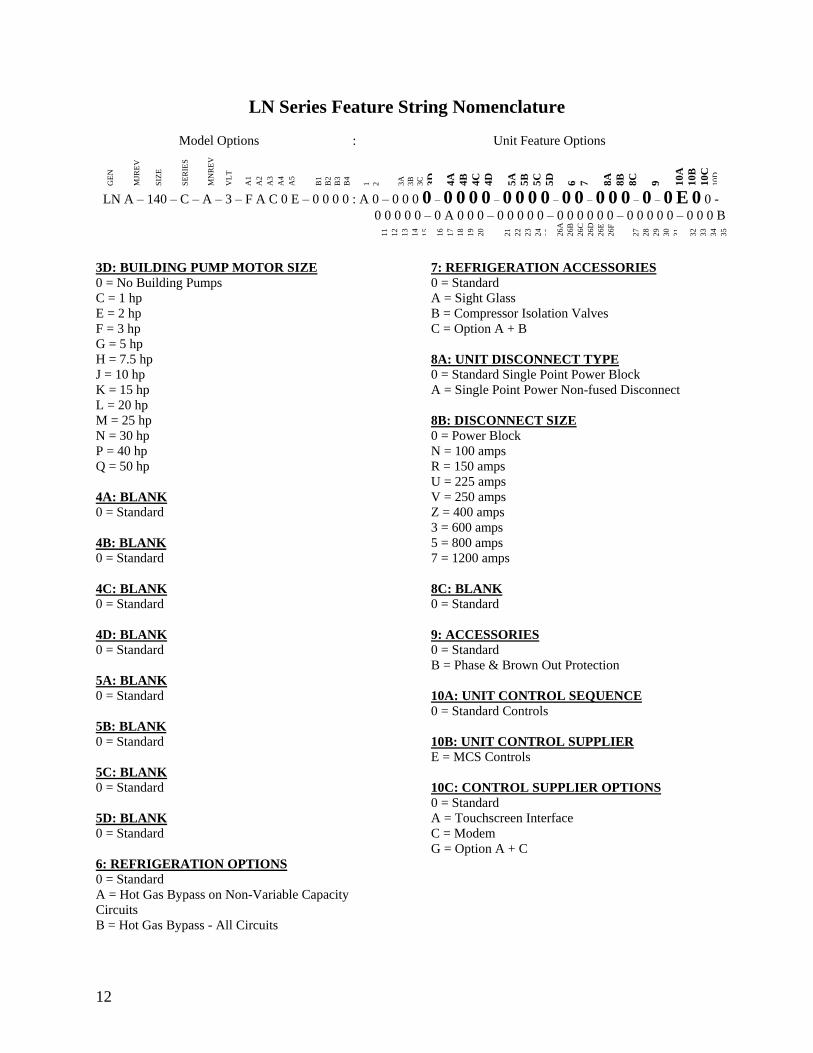
12
LN Series Feature String Nomenclature
GE
N
MJR
EV
S
IZE
SE
RIE
S
MN
RE
V
VL
T
A1
A2
A3
A4
A5
B1
B2
B3
B4
1
2
3A
3B
3C
3D
4
A
4B
4C
4D
5A
5B
5C
5D
6
7
8A
8B
8C
9
1
0A
10
B
10
C
10D
LN A ndash 140 ndash C ndash A ndash 3 ndash F A C 0 E ndash 0 0 0 0 A 0 ndash 0 0 0 0 ndash 0 0 0 0 ndash 0 0 0 0 ndash 0 0 ndash 0 0 0 ndash 0 ndash 0 E 0 0 -
0 0 0 0 0 ndash 0 A 0 0 0 ndash 0 0 0 0 0 ndash 0 0 0 0 0 0 ndash 0 0 0 0 0 ndash 0 0 0 B
11
12
13
14
15
16
17
18
19
20
21
22
23
24
25
26A
26B
26C
26D
26E
26F
27
28
29
30
31
32
33
34
35
3D BUILDING PUMP MOTOR SIZE
0 = No Building Pumps
C = 1 hp
E = 2 hp
F = 3 hp
G = 5 hp
H = 75 hp
J = 10 hp
K = 15 hp
L = 20 hp
M = 25 hp
N = 30 hp
P = 40 hp
Q = 50 hp
4A BLANK
0 = Standard
4B BLANK
0 = Standard
4C BLANK
0 = Standard
4D BLANK
0 = Standard
5A BLANK
0 = Standard
5B BLANK
0 = Standard
5C BLANK
0 = Standard
5D BLANK
0 = Standard
6 REFRIGERATION OPTIONS
0 = Standard
A = Hot Gas Bypass on Non-Variable Capacity
Circuits
B = Hot Gas Bypass - All Circuits
7 REFRIGERATION ACCESSORIES
0 = Standard
A = Sight Glass
B = Compressor Isolation Valves
C = Option A + B
8A UNIT DISCONNECT TYPE
0 = Standard Single Point Power Block
A = Single Point Power Non-fused Disconnect
8B DISCONNECT SIZE
0 = Power Block
N = 100 amps
R = 150 amps
U = 225 amps
V = 250 amps
Z = 400 amps
3 = 600 amps
5 = 800 amps
7 = 1200 amps
8C BLANK
0 = Standard
9 ACCESSORIES
0 = Standard
B = Phase amp Brown Out Protection
10A UNIT CONTROL SEQUENCE
0 = Standard Controls
10B UNIT CONTROL SUPPLIER
E = MCS Controls
10C CONTROL SUPPLIER OPTIONS
0 = Standard
A = Touchscreen Interface
C = Modem
G = Option A + C
Model Options Unit Feature Options
13
LN Series Feature String Nomenclature
Model Options Unit Feature Options
GE
N
MJR
EV
S
IZE
SE
RIE
S
MN
RE
V
VL
T
A1
A2
A3
A4
A5
B1
B2
B3
B4
1
2
3A
3B
3C
3D
4A
4B
4C
4D
5A
5B
5C
5D
6
7
8A
8B
8C
9
10A
10B
10C
10
D
LN A ndash 140 ndash C ndash A ndash 3 ndash F A C 0 E ndash 0 0 0 0 A 0 ndash 0 0 0 0 ndash 0 0 0 0 ndash 0 0 0 0 ndash 0 0 ndash 0 0 0 ndash 0 ndash 0 E 0 0 ndash
0 0 0 0 0 ndash 0 A 0 0 0 ndash 0 0 0 0 0 ndash 0 0 0 0 0 0 ndash 0 0 0 0 0 ndash 0 0 0 B
11
12
13
14
15
16
17
18
19
20
21
22
23
24
25
26
A
26
B
26
C
26D
26E
26F
27
28
29
30
31
32
33
34
35
10D BMS CONNECTION amp DIAGNOSTICS
0 = None
A = BACnet IP
B = BACnet MSTP
C = Modbus IP
D = Modbus RTU
E = Lontalk
H = No BMS Connection with Diagnostics
J = BACnet IP with Diagnostics
K = BACnet MSTP with Diagnostics
L = Modbus IP with Diagnostics
M = Modbus RTU with Diagnostics
N = Lontalk with Diagnostics
11 BLANK
0 = Standard
12 VESTIBULE ACCESSORIES
0 = Standard
C = Vestibule Heating (Electric)
13 MAINTENANCE ACCESSORIES
0 = Standard
A = 115VAC Convenience Outlet Factory Wired
B = 115VAC Convenience Outlet Field Wired
C = Service Lights
F = Options A + C
J = Options B + C
14 BLANK
0 = Standard
15 CODE OPTIONS
0 = Standard ETL USA Listing
A = Chicago Code
B = ETL USA + Canada Listing
16 SHIPPING SPLITS
0 = One Piece Unit
17 AIR-COOLED CHILLER ACCESSORIES
H = Cond Coil Guards + Three Phase Cond Fan
Motor + Fan Cycling- 35degF Low Ambient
J = Cond Coil Guards + VFD Cond Fan Head
Pressure Control - 0degF Low Ambient
18 BLANK
0 = Standard
19 BLANK
0 = Standard
20 BLANK
0 = Standard
21 BLANK
0 = Standard
22 BLANK
0 = Standard
23 BLANK
0 = Standard
24 CHILLER ACCESSORIES 1
0 = Standard
A = Glycol Chiller
C = Thermometers amp Pressure Gauges
G = Option A + C
25 BLANK
0 = Standard
26A BLANK
0 = Standard
26B BLANK
0 = Standard
26C BLANK
0 = Standard
14
LN Series Feature String Nomenclature
Model Options Unit Feature Options
GE
N
MJR
EV
S
IZE
SE
RIE
S
MN
RE
V
VL
T
A1
A2
A3
A4
A5
B1
B2
B3
B4
1
2
3A
3B
3C
3D
4A
4B
4C
4D
5A
5B
5C
5D
6
7
8A
8B
8C
9
10A
10B
10C
10D
LN A ndash 140 ndash C ndash A ndash 3 ndash F A C 0 E ndash 0 0 0 0 A 0 ndash 0 0 0 0 ndash 0 0 0 0 ndash 0 0 0 0 ndash 0 0 ndash 0 0 0 ndash 0 ndash 0 E 0 0 ndash
0 0 0 0 0 ndash 0 A 0 0 0 ndash 0 0 0 0 0 ndash 0 0 0 0 0 0 ndash 0 0 0 0 0 ndash 0 0 0 B
11
12
13
14
15
16
17
18
19
20
21
22
23
24
25
26A
26B
26C
26
D
26
E
26
F
27
28
29
30
31
3
2
33
34
35
26D BLANK
0 = Standard
26E BLANK
0 = Standard
26F BLANK
0 = Standard
27 BLANK
0 = Standard
28 BLANK
0 = Standard
29 BLANK
0 = Standard
30 BLANK
0 = Standard
31 BLANK
0 = Standard
32 BLANK
0 = Standard
33 WARRANTY
0 = Standard Warranty
D = Compressor Warranty Years 2-5
34 CABINET MATERIAL
0 = Standard - Double Wall + R-13 Foam Insulation
35 PAINT amp SPECIAL PRICING
AUTHORIZATIONS
B = Premium AAON Gray Paint Exterior
E = Premium AAON Gray Paint Exterior + Shrink
Wrap
X = Special Pricing Authorization + Premium AAON
Gray Paint Exterior
1 = SPA + Premium AAON Gray Paint Exterior +
Shrink Wrap
4 = Special Pricing Authorization + Special Exterior
Paint Color
7 = SPA + Special Exterior Paint Color + Shrink
Wrap
15
General Information
AAON LN Series chillers are complete self-
contained liquid chilling units They are
assembled wired charged and run-tested
Models are available for air-cooled
applications Chiller primary pumping
packages are available as optional features
Codes and Ordinances
LN Series units have been tested and
certified by ETL in accordance with UL
Safety Standard 1995CSA C222 No 236
System should be sized in accordance with
the American Society of Heating
Refrigeration and Air Conditioning
Engineers Handbook
Installation of LN Series units must conform
to the ICC standards of the International
Mechanical Code the International Building
Code and local building plumbing and
waste water codes All appliances must be
electrically grounded in accordance with
local codes or in the absence of local codes
the current National Electric Code
ANSINFPA 70 or the current Canadian
Electrical Code CSA C221
Receiving Unit
When received the unit should be checked
for damage that might have occurred in
transit If damage is found it should be noted
on the carrierrsquos Freight Bill A request for
inspection by carrierrsquos agent should be made
in writing at once Nameplate should be
checked to ensure the correct model sizes and
voltages have been received to match the job
requirements
If repairs must be made to damaged goods
then the factory should be notified before any
repair action is taken in order to protect the
warranty Certain equipment alteration
repair and manipulation of equipment
without the manufacturerrsquos consent may void
the product warranty Contact AAON
Technical Support for assistance with
Improper installation adjustment alteration service or maintenance can cause property damage personal injury or loss of life Startup and service must be performed by a Factory Trained Service Technician
WARNING
The Clean Air Act of 1990 bans the intentional venting of refrigerant as of July 1 1992 Approved methods of recovery recycling or reclaiming must be followed
CAUTION
Coils and sheet metal surfaces present sharp edges and care must be taken when working with equipment
Failure to observe the following instructions will result in premature failure of your system and possible voiding of the warranty
WARNING
WARNING
16
handling damaged goods repairs and freight
claims (918) 382-6450
Storage
If installation will not occur immediately
following delivery store equipment in a dry
protected area away from construction traffic
and in the proper orientation as marked on the
packaging with all internal packaging in
place Secure all loose-shipped items
Chiller
Failure to observe the following instructions
will result in premature failure of your
system and possible voiding of the warranty
Never turn off the main power supply to the
unit except for complete shutdown When
power is cut off from the unit any
compressors using crankcase heaters cannot
prevent refrigerant migration This means the
compressor will cool down and liquid
refrigerant may accumulate in the
compressor The compressor is designed to
pump refrigerant gas and damage may occur
when power is restored if liquid enters the
compressor
Before unit operation the main power switch
must be turned on for at least 24 hours for
units with compressor crankcase heaters
This will give the crankcase heater time to
clear any liquid accumulation out of the
compressor before it is required to run
Rotation must be checked on all MOTORS AND COMPRESSORS of three phase units All motors to include and not be limited to pump motors and condenser fan motors should all be checked by a qualified service technician at startup and any wiring alteration should only be made at the unit power connection
CAUTION
Scroll compressors are directional and will be damaged by operation in the wrong direction Low pressure switches on compressors have been disconnected after factory testing Rotation should be checked by a qualified service technician at startup using suction and discharge pressure gauges and any wiring alteration should only be made at the unit power connection
CAUTION
CRANKCASE HEATER OPERATION
Units may be equipped with compressor crankcase heaters which should be energized at least 24 hours prior to cooling operation to clear any liquid refrigerant from the compressors
CAUTION
COMPRESSOR CYCLING
3 MINUTE MINIMUM OFF TIME To prevent motor overheating compressors must cycle off for a minimum of 3 minutes
3 MINUTE MINIMUM ON TIME To maintain the proper oil level compressors must cycle on for a minimum of 3 minutes The cycle rate must not exceed 6 starts per hour
WARNING
17
Never cut off the main power supply to the
unit except for complete shutdown Always
control the system from the building
management system or control panel never
at the main power supply (except for
emergency or for complete shutdown of the
system)
Scroll compressors must be on a minimum of
3 minutes and off for a minimum of 3
minutes The cycle rate must be no more than
6 starts per hour
The chiller is furnished with a pressure
differential switch that is factory installed
between the chilled water supply and return
connections This sensor must not be
bypassed since it provides a signal to the unit
controller that water flow is present in the
heat exchanger and the unit can operate
without the danger of freezing the liquid
Compressor life will be seriously shortened
by reduced lubrication and the pumping of
excessive amounts of liquid oil and liquid
refrigerant
Wiring Diagrams
A complete set of unit specific wiring
diagrams in both ladder and point-to-point
form are laminated in plastic and located
inside the control compartment door
General Maintenance
When the initial startup is made and on a
periodic schedule during operation it is
necessary to perform routine service checks
on the performance of the chiller This
includes reading and recording suction
pressures and checking for normal sub-
cooling and superheat See the air-cooled
condenser sections in this manual for specific
details
Chiller Primary Pumping
Primary pumping uses a single pump to move
water (or glycol) through the chiller barrel
and back to the building This pumping
package provides a constant or variable flow
of water to the system The pump is activated
whenever the chiller is given a run signal
Water enters the unit through the return water
piping and then travels through an air
separator to remove any air that is entrapped
in the water Following this the water flows
through a suction guide with strainer The
end of the suction guide is removable for
strainer access The strainer assembly is
composed of two parts the operational
strainer and the startup strainer (located
inside the operational strainer) which is to be
removed 24 hours after startup
The pump is installed after the suction guide
and before a combination valve (Flo-Trex)
This combination valve acts as isolation
valve check valve and flow balancing valve
The shell and tube or brazed plate evaporator
is placed after the combination valve in the
water circuit with a flow switch installed
across its inlet and outlet This flow switch
closes when the velocity is above 07 feet per
second The closing flow switch signals the
control system to indicate flow through the
heat exchanger and allow cooling to activate
as required to maintain the setpoint The
water exiting the chiller evaporator leaves the
unit through the water out connection
18
Automatic Air Vent
There is an automatic air vent installed at the
high point of the system inside the pumping
package compartment The air vent valve
must be in the proper position for operation
Ensure that the small vent cap is loosened two
turns from the closed position allowing air to
be vented from the system It is advisable to
leave the cap on to prevent impurities from
entering the valve See appendix for
additional information
Dual Pumps
When redundant pumping is required factory
installed dual pumps can be ordered A dual
pump is a pump with two independent motors
and pumps in a single casing This dual pump
has a swing split-flapper valve in the
discharge port to prevent liquid recirculation
when only one pump is operating Isolation
valves in the casing allow one pump to be
isolated and removed for service while the
other pump is still operating
The controls package will activate the pump
when the unit is given a run command If the
controls do not recognize flow in 60 seconds
the second pump will be activated and an
alarm signal will be generated If the second
pump does not activate the cooling will be
locked out See appendix for additional
information
Pressure Gauges and Thermometers
Pressure gauges and thermometers are
available as a factory installed option
Thermometers are installed on the inlet and
outlet of the unit One pressure gauge is
installed at each pump This pressure gauge
is connected in three places to the water
piping before the suction guidestrainer after
the suction guide and before the pump and
after the pump There is also a needle valve
at each of these points to isolate the pressure
To measure the pressure at any given point
open the needle valve at that point and close
the other two needle valves One gauge is
used so that the calibration of the pressure
gauge is irrelevant in the calculation of the
differential pressure
Pipe Insulation
The water piping and components on units
with pumping packages are not insulated at
the factory Insulation should be installed on
the water piping after the system has been
checked for leaks
19
Installation
Chiller Placement
The AAON LN Series is designed for
outdoor applications and mounting at ground
level or on a rooftop It must be placed on a
level and solid foundation that has been
prepared to support its weight
The placement relative to the building air
intakes and other structures must be carefully
selected Be sure to observe the dimensions
that are on the rating plate of the chiller for
operational and service clearances
Table 1 - Service Clearances
Location Unit Size
45-140 tons
Front -
(Controls Side) 72rdquo
Back 72rdquo
Ends 96rdquo
Top Unobstructed
Condenser coils and fans must be free of any
obstructions in order to start and operate
properly with a correct amount of airflow
For proper unit operation the immediate area
around condenser must remain free of debris
that may be drawn in and obstruct airflow in
the condensing section
Consideration must be given to obstruction
caused by snow accumulation when placing
the unit
Curb and Steel Mount Installation
Make openings in the roof decking large
enough to allow for water piping electrical
penetrations and workspace only Do not
make openings larger than necessary Set the
curb to coincide with the openings Make
sure curb is level
If the LN is installed on a curb use a curb cap
for the open area under the condenser section
Unit specific curb drawing is included with
job submittal See SMACNA Architectural
Sheet Metal Manual for curb installation
details
Units require rail support along all four sides
of the unit base
When installed at ground level a one-piece
concrete slab should be used with footings
that extend below the frost line Care must
also be taken to protect the coil and fins from
damage due to vandalism or other causes
If unit is elevated a field supplied catwalk is
recommended to allow access to unit service
doors
This unit ships with a curb gasket that is 1frac14rdquo
wide and 1frac12rdquo tall It is recommended that this
or another similar gasket be used between the
curb and the unit to reduce vibration from the
unit to the building
All roofing work should be performed by competent roofing contractors to avoid any possible leakage
CAUTION
Figure 1 - LN Base
20
Figure 2 - Curb Mounting with Dimensions
Figure 3 - Steel Mounting Rail with
Dimensions
Table 2 - Mounting Dimensions
Tons A B C D
45-140 142rdquo 138rdquo 134rdquo 139rdquo
Figure 2
Figure 3
Lifting and Handling
If cables or chains are used to hoist the unit
they must be the same length and care should
be taken to prevent damage to the cabinet
See Figure 5 and Figure 6 for additional
information
Before lifting unit be sure that all shipping
material has been removed from unit Secure
hooks and cables at all lifting points lugs
provided on the unit
Hoist unit to a point directly above the curb
or mounting rail Be sure that the gasket
material has been applied to the curb or
mounting rail
Carefully lower and align unit with utility and
duct openings Lower the unit until the unit
skirt fits around the curb Make sure the unit
is properly seated on the curb and is level
Figure 4 - Lifting Points
21
Figure 5 - Lifting Detail of a 45-60 ton Unit
Figure 6 - Lifting Detail of a 75-140 ton Unit
Lifting slot locations are unit specific
Unit must be rigged at all marked lifting points
22
Water Connection
Connect the supply and return water lines
The connection size is listed on the unit rating
sheet along with the designed volumetric
flow rate The maximum operating pressure
for AAON LN Series units is 125 psi
Mounting Isolation
For roof mounted applications or anytime
vibration transmission is a factor vibration
isolators may be used
Access Doors
Lockable access door is provided to the
compressor and control compartment A
separate access door is also provided to the
pumping package compartment
A light switch with service lights is provided
on the wall of the compressor and control
compartment
End Flashing Installation
On all LN Series units the cabinet width will
overhang the shipping trailer on each side
In order to secure and protect the unit during
transit the sheet metal end flashings have
been removed from the unit The slot created
at the base of each end of the unit allows the
unit to set firmly on the trailer deck
Sheet metal flashings are shipped loose with
the unit and once the unit is set into place the
flashings must be installed on each end of the
unit to complete the finished seal at the base
The flashings are unit specific and designed
to cover the slot at each end of the unit to
prevent water run-off into the curb
Failure to attach and seal the end of unit with
the flashings may result in water leakage into
the curb
Figure 7 - Factory Supplied End Flashings
PVC (Polyvinyl Chloride) and CPVC (Chlorinated Polyvinyl Chloride) are vulnerable to attack by certain chemicals Polyolester (POE) oils used with R-410A and other refrigerants even in trace amounts in a PVC or CPVC piping system will result in stress cracking of the piping and fittings and complete piping system failure
CAUTION
The chiller must be operated only with liquid flowing through the evaporators
WARNING
Installing Contractor is responsible for proper sealing of the water piping entries into the unit Failure to seal the entries may result in damage to the unit and property
CAUTION
23
Low Ambient Operation
If the chiller is ordered for a Low Ambient
application the liquid system must use a
glycol solution and the piping must be
insulated to be prepared for freezing
conditions Care must be taken in the source
of electrical power for the heating tape and
thermostat
Electrical
The single point electrical power connections
are made in the electrical control
compartment
The microprocessor control furnished with
the unit is supplied with its own power supply
factory wired to the main power of the
outdoor mechanical room
Verify the unit nameplate voltage agrees with
the power supply Connect power and control
field wiring as shown on the unit specific
wiring diagram provided with the unit
Size supply conductors based on the unit
MCA rating Supply conductors must be
rated a minimum of 167degF (75degC)
Route power and control wiring separately
through the utility entry Do not run power
and signal wires in the same conduit
Protect the branch circuit in accordance with
code requirements The unit must be
electrically grounded in accordance with
local codes or in the absence of local codes
the current National Electric Code
ANSINFPA 70 or the current Canadian
Electrical Code CSA C221
Power wiring is to the unit terminal block or
main disconnect All wiring beyond this point
has been done by the manufacturer and
cannot be modified without effecting the
units agencysafety certification
Figure 8 - Front View of Utility Entry and
Power Switch from Control Compartment
Electric shock hazard Before attempting to perform any installation service or maintenance shut off all electrical power to the unit at the disconnect switches Unit may have multiple power supplies Failure to disconnect power could result in dangerous operation serious injury death or property damage
WARNING
In order to prevent water leakage into the roof curb the factory provided sheet metal flashings MUST BE attached to the unit base to cover the shipping slots at both ends of the unit
CAUTION
24
Startup technician must check for proper
motor rotation and check fan motor amperage
listed on the motor nameplate is not
exceeded Motor overload protection may be
a function of the variable frequency drive and
must not be bypassed
Note All units are factory wired for
208230V 460V or 575V If unit is to be
connected to a 208V supply the transformer
must be rewired to 208V service For 208V
service interchange the yellow and red
conductor on the low voltage control
transformer
Red-Black for 208V
Yellow-Black for 230V
Wire control signals to the unitrsquos low voltage
terminal block located in the controls
compartment All wiring beyond this point
has been completed by the manufacturer and
cannot be modified without effecting the
unitrsquos agencysafety certification
If any factory installed wiring must be
replaced use a minimum 221degF (105degC) type
AWM insulated conductors
Supply voltage must be within the minmax
range shown on the unit nameplate Available
short circuit current should not exceed the
short circuit current rating (SCCR) shown on
the unit nameplate
Three phase voltage imbalance will cause
motor overheating and premature failure
The maximum allowable imbalance is 5
Voltage imbalance is defined as 100 times the
maximum deviation from the average voltage
divided by the average voltage
Example
(218V+237V+235V)3 = 230V then
100(230V-218V)230V = 52 which
exceeds the allowable imbalance
Check voltage imbalance at the unit
disconnect switch and at the compressor
terminal Contact your local power company
for line voltage corrections
Three phase voltage imbalance will cause motor overheating and premature failure
CAUTION
Scroll compressors are directional and will be damaged by operation in the wrong direction Low pressure switches on compressors have been disconnected after factory testing Rotation should be checked by a qualified service technician at startup using suction and discharge pressure gauges and any wiring alteration should only be made at the unit power connection
Installing Contractor is responsible for proper sealing of the electrical and gas entries into the unit Failure to seal the entries may result in damage to the unit and property
CAUTION CAUTION
25
Variable Speed Compressors
Variable speed compressors should not be
operated outside the factory determined
frequency range The factory determined
compressor VFD frequency range is given
below in Table 3
Table 3- Tandem Circuited Variable Speed
Compressor VFD Frequency Range
Model (LN-) Compressor VFD
Range (Hz)
208V 230V 460V and 575V Units
045 055 060 45-65Hz
075 45-70Hz
095 105 120 35-60 Hz
140 35-65 Hz
No variable speed compressor shall operate below 35 Hz Operating variable speed compressors outside the frequency range specified in this manual voids all warranties and may result in compressor failure
CAUTION
Rotation must be checked on all MOTORS AND COMPRESSORS of three phase units Condenser fan motors should all be checked by a qualified service technician at startup and any wiring alteration should only be made at the unit power connection Variable frequency drives are programmed to automatically rotate the fan in the correct rotation Do not rely on fans with variable frequency drives for compressor rotation
CAUTION
26
Startup (See back of the manual for startup form)
Before the startup of the chiller be sure that
the following items have been checked
1 Verify that electrical power is available to
the unit
2 Verify that any remote stopstart device
connected to the chiller controller is
requesting the chiller to start
3 Verify that liquid flow is present through
the chiller from the building
4 There should be a building load of at least
25 of the chiller capacity in order to
properly check operation
5 With the main power switch off review
the MCS Controller Manual provided
with the chiller Understand the keypad
functions how to set the leaving water
temperature setpoint and how to initiate
the Run State
Use the general check list at the top of the
startup form to make a last check that all the
components are in place water flow is
present and the power supply is energized
Using the controller keypad individually set
the outputs in ldquoManual Onrdquo to confirm relay
closure and compressor operation
Cycle through all the compressors to confirm
that all are operating within tolerance
While performing the check use the startup
form to record observations of compressor
amps and refrigerant pressures
When all is running properly place the
controller in the Run mode and observe the
system until it reaches a steady state of
operation
Note For more information on programming
the controller refer to the MCS Controller
manual provided with the chiller
Electric shock hazard Shut off all electrical power to the unit to avoid shock hazard or injury from rotating parts
WARNING
Improper installation adjustment alteration service or maintenance can cause property damage personal injury or loss of life Startup and service must be performed by a Factory Trained Service Technician
WARNING
Rotation must be checked on all MOTORS AND COMPRESSORS of three phase units All motors to include and not be limited to pump motors and condenser fan motors should all be checked by a qualified service technician at startup and any wiring alteration should only be made at the unit power connection
CAUTION
Before completing installation a complete operating cycle should be observed to verify that all components are functioning properly
CAUTION
27
Axial Flow Condenser Fans
Multi-Wing Z Series Aluminum Fan Blade
Pitch Angle Setting Instructions
1 Maintain the balance of fan
Mark the hub castings across a joint so the
fan hub can be reassembled in the same
orientation
Mark the location of any balancing weight
Balancing weight will be on the outer bolt
circle in the form of washers andor longer
bolts or an additional balancing nut
Number the blades and blade sockets so that
they are replaced into their original position
Figure 9 - Fan with the HUB on the top and
RET on the bottom
2 Determine the direction of rotation
Right R is clockwise when facing the
discharge side of the fan and Left L is
counterclockwise when facing the discharge
side of the fan
3 Determine the bushing mount location
The bushing mount is the center section of the
hub through which the fan is mounted to the
shaft and typically contains either setscrews
or a center-tapered hole where the bushing
inserts
Location A is with the bushing mount on air
inlet side of the fan
Location B is with the bushing mount on air
discharge side of the fan
Figure 10 - Bushing Mount Location
4 Determine the pin location groove
Disassemble fan on a flat surface and note in
which groove the pin is located
Figure 11 - RET with Pin in Groove 4
Bushing
Mount
A B Bushing
Mount
Bushing Bushing
1 2 3 4
28
5 Determine whether the pin is in the HUB
or RET
Figure 12 - Fan HUB and RET Castings
6 Determine the current blade pitch and the pin location for the new blades
Table 4 - ReturnExhaust Fan Pin Location
Type Bushing
Mount
Blade Pitch Angle
20deg 25deg 28deg 30deg 33deg 35deg 38deg 40deg 45deg 50deg
5Z A - RET - RET RET RET HUB HUB HUB HUB
B - HUB - HUB HUB HUB RET RET RET RET
Table 5 - ReturnExhaust Fan Pin Location
Type Rot Blade Pitch Angle
20deg 25deg 28deg 30deg 33deg 35deg 38deg 40deg 45deg 50deg
5Z R - 4 - 3 2 1 4 3 2 1
L - 1 - 2 3 4 1 2 3 4
7 Replace fan blades in the new pin
location and reassemble the fan
Replace the blades with the pin in the 1 2 3
or 4 groove position of either the HUB or
RET Assemble the fan making sure to place
the blades in their previous blade sockets to
match up the previous orientation of HUB
and RET and to replace any balancing
weights in their previous locations Tighten
bolts in a cross pattern to 5-6 ft-lbs of torque
29
Multi-Wing W Series Black Glass
Reinforced Polypropylene Fan Blade Pitch
Angle Setting Instructions
Contact the AAON parts department to
acquire the new pitch pins for the fan blades
Note original position of retaining plates
center boss and all hardware including
additional hardware used for balancing
1 Remove all the bolts and nuts
2 Determine blade rotation ndash on the concave
side of the blade is a blade marking showing
6WR 6WL 7WL 7WR or 9WR The ldquoLrdquo
and ldquoRrdquo denote the rotation of the blade
3 Replace the pitch insert in the blade root
with an insert of the desired pitch
Figure 13 - Pitch Insert
4 Replace blades to their original location
5 Replace all nuts bolts and washers on the
fan hub
6 Replace retaining plates and center boss to
original location
7 Tighten nuts and bolts to 14 ft-lbs of
torque
Fan Assembly Bushings
The fan assembly bushings should be
tightened to the specifications listed in the
following table
Table 6 - Fan Assembly Bushing Torque
Specifications
Bushing Tightening Torque
(in-lbs)
H X 1125 95
H X 1375 95
SH X 1125 108
SH X 1375 108
SD X 1125 108
SD X 1375 108
SD X 1625 108
SD X 1875 108
SK X 2125 180
30
Maintenance
General
Qualified technicians must perform routine
service checks and maintenance This
includes reading and recording the
condensing and suction pressures and
checking for normal sub-cooling and
superheat
Air-cooled chillers require maintenance
schedulesprocedures Unit specific
instructions are included in this manual
Compressors
The scroll compressors are fully hermetic and
require no maintenance except keeping the
shell clean
Refrigerant Suction Line Filter
Each refrigerant circuit contains a
replaceable core suction line filter One
month after start-up remove the filter
element
The replaceable core suction filters are
provided with pressure taps and shutoff
valves for isolation when removing the filter
For safety purposes a service manifold must
be attached prior to filter maintenance
Suction Filter Removal Instructions
1 Shut down operation of the unit
2 Close both shut-off valves to isolate
the suction filter
3 Reclaim the refrigerant from the
suction filter section
4 Remove the bolts from the suction
filter end plate
5 Remove the pleated filter assembly
Prior to filter core service a service manifold MUST BE attached to in and out pressure connections to assure no pressure exists during filter maintenance Non-compliance could result in injury or violation of EPA regulations
Service gauges MUST BE connected before operating the isolation valves for the replaceable core filter
WARNING
WARNING
31
6 Replace the suction filter end plate
and bolts
7 Evacuate the suction filter assembly
to 500 microns
8 Open both shut-off valves
Adjusting Refrigerant Charge
All AAON chillers are shipped with a full
factory charge Periodically adjusting the
charge of a system may be required
Adjusting the charge of a system in the field
must be based on determination of liquid sub-
cooling and evaporator superheat On a
system with an expansion valve liquid sub-
cooling is more representative of the charge
than evaporator superheat but both
measurements must be taken
Before Charging
Refer to the unit nameplate as a reference
when determining the proper refrigerant
charge
Unit being charged must be at or near full
load conditions before adjusting the charge
Units equipped with hot gas bypass must
have the hot gas bypass valve closed to get
the proper charge
After adding or removing charge the system
must be allowed to stabilize typically 10-15
minutes before making any other
adjustments
The type of unit and options determine the
ranges for liquid sub-cooling and evaporator
superheat Refer to Table 7 when determining
the proper sub-cooling
For units equipped with low ambient (0degF)
option see the special charging instructions at
the end of this section
Checking Liquid Sub-cooling
Measure the temperature of the liquid line as
it leaves the condenser coil
Read the gauge pressure at the liquid line
close to the point where the temperature was
taken You must use liquid line pressure as it
will vary from discharge pressure due to
condenser coil pressure drop
Convert the pressure obtained to a saturated
temperature using the appropriate refrigerant
temperature-pressure chart
Subtract the measured liquid line temperature
from the saturated temperature to determine
the liquid sub-cooling
Compare calculated sub-cooling to the table
below for the appropriate unit type and
options
The Clean Air Act of 1990 bans the intentional venting of refrigerant (CFCrsquos and HCFCrsquos) as of July 1 1992 Approved methods of recovery recycling or reclaiming must be followed Fines andor incarceration may be levied for non-compliance
CAUTION
Polyolester (POE) and Polyvinylether (PVE) oils are two types of lubricants used in hydrofluorocarbon (HFC) refrigeration systems Refer to the compressor label for the proper compressor lubricant type
CAUTION
32
Checking Evaporator Superheat
Measure the temperature of the suction line
close to the compressor
Read gauge pressure at the suction line close
to the compressor
Convert the pressure obtained to a saturated
temperature using the appropriate refrigerant
temperature-pressure chart
Subtract the saturated temperature from the
measured suction line temperature to
determine the evaporator superheat
For refrigeration systems with tandem scroll
compressors it is critical that the suction
superheat setpoint on the expansion valve is
set with one compressor running The suction
superheat should be 10-13degF with one
compressor running The suction superheat
will increase with both compressors in a
tandem running Inadequate suction
superheat can allow liquid refrigerant to
return to the compressors which will wash the
oil out of the compressor Lack of oil
lubrication will destroy a compressor Liquid
sub-cooling should be measured with both
compressors in a refrigeration system
running
Compare calculated superheat to Table 7 for
the appropriate unit type and options
Table 7 - Acceptable Refrigeration Circuit
Values
Air-Cooled Chiller with Scroll
Compressors
Sub-Cooling2 12-18degF
Superheat1 10-15degF 1 One compressor running in tandem 2 Two compressors running in tandem
Adjusting Sub-cooling and Superheat
Temperatures
The system is overcharged if the sub-cooling
temperature is too high and the evaporator is
fully loaded (low loads on the evaporator
result in increased sub-cooling) and the
evaporator superheat is within the
temperature range as shown in Table 7 (high
superheat results in increased sub-cooling)
Correct an overcharged system by reducing
the amount of refrigerant in the system to
lower the sub-cooling
The system is undercharged if the superheat
is too high and the sub-cooling is too low
Correct an undercharged system by adding
refrigerant to the system to reduce superheat
and raise sub-cooling
If the sub-cooling is correct and the superheat
is too high the expansion valve may need
adjustment to correct the superheat
Expansion valves must be adjusted to approximately 10-15degF of suction superheat Failure to have sufficient superheat will damage the compressor and void the warranty
CAUTION
DO NOT OVERCHARGE Refrigerant overcharging leads to excess refrigerant in the condenser coils resulting in elevated compressor discharge pressure
CAUTION
33
Table 8 - R-410A Refrigerant Temperature-Pressure Chart
F psig F psig F psig F psig F psig
20 783 50 1422 80 2349 110 3641 140 5401
21 800 51 1448 81 2386 111 3691 141 5470
22 818 52 1474 82 2423 112 3742 142 5539
23 836 53 1501 83 2460 113 3794 143 5609
24 854 54 1528 84 2498 114 3846 144 5679
25 872 55 1555 85 2537 115 3899 145 5751
26 891 56 1582 86 2575 116 3952 146 5823
27 910 57 1610 87 2614 117 4005 147 5896
28 929 58 1638 88 2654 118 4059 148 5969
29 949 59 1667 89 2694 119 4114 149 6044
30 968 60 1696 90 2735 120 4169 150 6119
31 988 61 1725 91 2776 121 4225
32 1009 62 1754 92 2817 122 4282
33 1029 63 1784 93 2859 123 4339
34 1050 64 1815 94 2901 124 4396
35 1071 65 1845 95 2944 125 4454
36 1092 66 1876 96 2987 126 4513
37 1114 67 1907 97 3030 127 4573
38 1136 68 1939 98 3075 128 4632
39 1158 69 1971 99 3119 129 4693
40 1181 70 2004 100 3164 130 4754
41 1203 71 2036 101 3210 131 4816
42 1227 72 2070 102 3256 132 4878
43 1250 73 2103 103 3302 133 4941
44 1274 74 2137 104 3349 134 5005
45 1298 75 2171 105 3396 135 5069
46 1322 76 2206 106 3444 136 5134
47 1347 77 2241 107 3493 137 5200
48 1372 78 2277 108 3542 138 5266
49 1397 79 2313 109 3591 139 5333
34
Lubrication
All original motors and bearings are
furnished with an original factory charge of
lubrication Certain applications require
bearings be re-lubricated periodically The
schedule will vary depending on operating
duty temperature variations or severe
atmospheric conditions
Bearings should be re-lubricated at normal
operating temperatures but not when
running
Rotate the fan shaft by hand and add only
enough grease to purge the seals DO NOT
OVERLUBRICATE
Air-Cooled Condenser
The air-cooled condenser section rejects heat
by passing outdoor air over the fin tube coils
for cooling of the hot refrigerant gas from the
compressors The heated air will discharge
from the top of the section through the axial
flow fans
The condenser coils should be inspected
yearly to ensure unrestricted airflow If the
installation has a large amount of airborne
dust or other material the condenser coils
should be cleaned according to the
microchannel coil cleaning section
Brazed Plate Heat Exchanger Cleaning
Because of a normally high degree of
turbulence in brazed plate heat exchangers
for many applications the heat exchanger
channels are self-cleaning For applications
that are not self-cleaning (ie hard water at
high temperatures etc) or applications where
additional cleaning is desired it is possible to
clean the brazed plate heat exchanger by
circulating a cleaning liquid
Use a tank with weak acid 5 phosphoric
acid (H3PO4) or if the exchanger is
frequently cleaned 5 oxalic acid (H2C2O4)
Pump the cleaning liquid through the
exchanger For optimum cleaning the
cleaning solution flow rate should be a
minimum of 15 times the normal flow rate
preferably in a back-flush mode After
cleaning the heat exchanger must be rinsed
with clean water A solution of 1-2 sodium
hydroxide (NaOH) or sodium bicarbonate
(NaHCO) before the last rinse ensures that all
acid is neutralized
E-Coated Coil Cleaning
Documented quarterly cleaning of e-coated
coils is required to maintain coating warranty
coverage
Surface loaded fibers or dirt should be
removed prior to water rinse to prevent
restriction of airflow If unable to back wash
the side of the coil opposite of the coils
entering air side then surface loaded fibers or
dirt should be removed with a vacuum
cleaner If a vacuum cleaner is not available
a soft non-metallic bristle brush may be used
In either case the tool should be applied in
the direction of the fins Coil surfaces can be
easily damaged (fin edges bent over) if the
tool is applied across the fins
Use of a water stream such as a garden hose
against a surface loaded coil will drive the
fibers dirt and salts into the coil This will
make cleaning efforts more difficult Surface
loaded fibers must be completely removed
prior to using low velocity clean water rinse
Electric shock hazard Shut off all electrical power to the unit to avoid shock hazard or injury from rotating parts
WARNING
35
Quarterly cleaning is required to maintain
warranty coverage and is essential to
maintain the life of an E-coated coil Coil
cleaning shall be part of the units regularly
scheduled maintenance procedures
Failure to clean an E-coated coil on the
prescribed quarterly cycle will void the
warranty and may result in reduced
efficiency and durability in the environment
A routine two-step quarterly coil cleaning is
required to maintain warranty
Step one is to clean the coil with the below
approved coil cleaner (see approved products
list under the Recommended Coil Cleanersrdquo
section
Step two is to use the approved saltchloride
remover under the Recommended Chloride
Removerrdquo section to dissolve soluble salts
and revitalize the unit It is very important
when cleaning andor rinsing not to exceed
130degF and potable water pressure is less than
100 psig to avoid damaging the unit and coil
fin edges
For routine quarterly cleaning first clean the
coil with the below approved coil
cleaner After cleaning the coils with the
approved cleaning agent use the approved
chloride remover to remove soluble salts and
revitalize the unit
Recommended Coil Cleaner ndash Step 1
GulfCoatTM Coil Cleaner assuming it is
used in accordance with the manufacturers
directions on the container for proper mixing
and cleaning has been approved for use on
E-coated coils to remove mold mildew dust
soot greasy residue lint and other
particulate Never use any cleaners that are
not approved
Recommended Chloride Remover ndash Step 2
CHLORRIDreg Concentrate assuming it
is used in accordance with the manufacturers
directions on the container for proper mixing
has been approved for use on E-coated coils
to remove chloridessalts amp sulfates Never
use any chloride removers that are not
approved
Warranty Protection ndash Step 1
Complete the coil cleaning following these
steps
1 Ensure that the power to the unit is off
and locked out
2 Clean the area around the unit if
needed to ensure leaves grass or
High velocity water from a pressure washer or compressed air should only be used at a very low pressure to prevent fin andor coil damages The force of the water or air jet may bend the fin edges and increase airside pressure drop Reduced unit performance or nuisance unit shutdowns may occur
Harsh chemicals household bleach or acid cleaners should not be used to clean e-coated coils These cleaners can be very difficult to rinse out of the coil and can accelerate corrosion and attack the e-coating If there is dirt below the surface of the coil use the recommended coil cleaners
CAUTION
CAUTION
36
loose debris will not be blown into the
coil
3 Remove panels or tops as required
gaining access to the coil(s) to be
cleaned
4 Using a pump up sprayer fill to the
appropriate level with potable water
and add the correct amount of
approved cleaner as per manufacture
instructions leaving room for the
pump plunger to be reinserted
NOTE Coils should always be cleaned
back flushed opposite of airflow to prevent
impacting the dirt into the coil
5 If the coils have heavy dirt fibers
grass leaves etc on the interior or
exterior face areas a vacuum and
brush should be used to remove those
surface contaminants prior to
applying cleaner The interior floor
drain tray or pan areas should also be
vacuumed
6 Apply the mixed cleaner to coil
surfaces using a pressurized pump up
sprayer maintaining a good rate of
pressure and at a medium size nozzle
spray (not a solid stream and not a
wide fan but somewhere in the
middle) Work in sectionspanels
ensuring that all areas are covered and
kept wetted
7 Apply the cleaner to unit interior air
exiting side coil surfaces first Work
in sectionspanels moving side to side
and from top to bottom
8 Generously soak coils by spraying
cleaner directly on and into the fin
pack section to be cleaned and allow
the cleaning solution to soak for 5 to
10 minutes
9 Using pressurized potable water
(lt100 psi) rinse the coils and
continue to always work in
sectionspanels Start at the top of the
coil and slowly move vertically
downward to the bottom Then
staying in the same vertical area
slowly move back up to the top where
you started Now move over slightly
overlapping the area just completed
and repeat above Continue until all
coil areas on the inside of the unit
have been rinsed
10 Complete steps 5-9 for the exterior air
entering side of the coils
11 Final rinse ndash Now complete a quick
rinse of both sides of the coil
including the headers piping u-
bends and hairpins
12 If the coil has a drain pan or unit floor
that is holding rinse water or cleaner
extra time and attention will need to
be taken in those areas to ensure a
proper rinse has been completed
Warranty Protection ndash Step 2
Complete the coil chloride (salt) removal
following these steps
1 CHLORRIDreg is a concentrate to be
used for both normal inland
applications at a 1001 mix ratio OR
for severe coastal applications 501
mix ratio with potable water (256
ounces of Chlorrid to 1 gal of water)
Using a pump up sprayer fill to the
appropriate level with potable water
and add the correct amount of
CHLORRIDreg salt remover leaving
room for the pump plunger to be
reinserted
2 Apply CHLORRIDreg to all external
coil surfaces using a pressurized
pump up sprayer maintaining a good
rate of pressure and at a medium size
nozzle spray (not a solid stream and
not a wide fan but somewhere in the
middle) Work in sectionspanels
ensuring that all areas are covered and
kept wetted
37
3 Generously soak coils by spraying
CHLORRIDreg directly on and into
the fin pack section Let stand for 5 to
10 minutes keeping the area wetted
Do not allow to dry before rinsing
4 Using pressurized potable water
(lt100 psi) rinse the CHLORRIDreg
and dissolved chloridessalts off of
the coils continuing to always work in
sectionspanels
5 Starting at the top of the coil begin
rinsing the coil from side to side until
you reach the bottom Repeat as many
times as is necessary to ensure all coil
sectionspanels have been completed
and are thoroughly rinsed
6 Reinstall all panels and tops that were
removed
Microchannel Coil Cleaning
Documented routine cleaning of
microchannel coils with factory provided e-
coating is required to maintain coating
warranty coverage See E-Coated Coil
Cleaning section
Air-cooled heat exchangers may include
microchannel coils
Cleaning microchannel coils is necessary in
all locations In some locations it may be
necessary to clean the coils more or less often
than recommended In general a condenser
coil should be cleaned at a minimum of once
a year In locations where there is commonly
debris or a condition that causes dirtgrease
build up it may be necessary to clean the coils
more often Proper procedure should be
followed at every cleaning interval Using
improper cleaning technique or incorrect
chemicals will result in coil damage system
performance fall off and potentially leaks
requiring coil replacement
Documented routine cleaning of
microchannel coils with factory provided e-
coating is required to maintain coating
warranty coverage Use the E-Coated Coil
Cleaning section for details on cleaning e-
coated coils
Field applied coil coatings are not
recommended with microchannel coils
Allowed Chemical Cleaners and Procedures
AAON recommends certain chemicals that
can be used to remove buildup of grime and
debris on the surface of microchannel coils
These chemicals have been tested for
performance and safety and are the only
chemicals that AAON will warrant as correct
for cleaning microchannel coils
There are three procedures that are outlined
below that will clean the coils effectively
without damage to the coils Use of any other
procedure or chemical may void the warranty
to the unit where the coil is installed With
all procedures make sure the unit is off
before starting
The water pressure used to clean should not
exceed 140 psi from no closer than 6 inches
from the coils and with the water aimed
perpendicular to the coils
Electric shock hazard Shut off all electrical power to the unit to avoid shock hazard or injury from rotating parts
WARNING
WARNING
38
1 Simple Green
Simple Green is available from AAON Parts
and Supply (Part T10701) and is
biodegradable with a neutral 65 pH
Recommendation is to use it at a 4 to 1 mix
Use the following procedure
1 Rinse the coil completely with water Use
a hard spray but be careful not to bend or
damage the fins A spray that is too hard
will bend the fins Spray from the fan side
of the coil
2 With a pump sprayer filled with a mix of
4 parts water to one part Simple Green
spray the air inlet face of the coil Be sure
to cover all areas of the face of the coil
3 Allow the coil to soak for 10-15 minutes
4 Rinse the coil with water as in step one
5 Repeat as necessary
2 Vinegar
This is standard white vinegar available in
gallons from most grocery stores It has a pH
of 2-3 so it is slightly acidic Use the
following procedure
1 Rinse the coil completely with water Use
a hard spray but be careful not to bend or
damage the fins A spray that is too hard
will bend the fins Spray from the fan side
of the coil
2 Use a pump sprayer filled with vinegar
(100) Spray from the face of the coil in
the same direction as the airflow Be sure
to cover all areas of the face of the coil
3 Allow the coil to soak for 10-15 minutes
4 Rinse the coil with water as in step one
5 Repeat as necessary
3 Water Flush
This procedure can be used when the only
material to cause the coil to need cleaning is
debris from plant material that has impinged
the coil face
1 Rinse the coil completely with water Use
a hard spray but be careful not to bend or
damage the fins A spray that is too hard
will bend the fins Spray from the fan side
of the coil
2 Spray and rinse the coil from the face
Application Examples
The three procedures can be used to clean
microchannel coils They will fit with the
application depending on the area In some
areas where the springsummer has a large
cottonwood bloom 3 might work fine if the
unit is installed on an office building and no
other environmental factors apply
When a unit is installed where the sprinkler
system has water being sprayed onto the
condenser coil you might have better results
using 2 Vinegar is slightly acidic and may
help with the calcium build up from drying
water This also works well when grease is
part of the inlet air to a condenser coil
Generally the best and broadest based
procedure is 1 The grease cutting effect of
the Simple Green is good for restaurant
applications
Other Coil Cleaners
There are many cleaners on the market for
condenser coils Before using any cleaner
that is not covered in this section you must
get written approval from the AAON
warranty and service department Use of
unapproved chemicals will void the
warranty
Use pressurized clean water with pressure not to exceed 140 psi Nozzle should be 6rdquo and 80deg to 90deg from coil face Failure to do so could result in coil damage
CAUTION
39
AAON testing has determined that unless a
chemical has a neutral pH (6-8) it should not
be used
Beware of any product that claims to be a
foaming cleaner The foam that is generated
is caused by a chemical reaction to the
aluminum fin material on tube and fin coils
and with the fin tube and coating material on
microchannel coils
Microchannel coils are robust in many ways
but like any component they must be treated
correctly This includes cleaning the coils
correctly to give optimal performance over
many years
Service
If the unit will not operate correctly and a
service company is required only a company
with service technicians qualified and
experienced in both refrigerant chillers and
air conditioning are permitted to service the
systems to keep warranties in effect If
assistance is required the service technician
must contact AAON
Replacement Parts
Parts for AAON equipment may be obtained
from your local AAON representative When
ordering parts reference the unit serial
number and part number
AAON Technical Support
2424 S Yukon Ave
Tulsa OK 74107
Ph (918) 382-6450
techsupportAAONcom
wwwAAONcom
Note Before calling technician should have
model and serial number of the unit available
for the service department to help answer
questions regarding the unit
40
Appendix - Water Piping Component Information
Automatic Air Vent Valves
Automatic Air Vent Valves provide
automatic air venting for hot or cold water
distribution systems These vents purge air
that may be in the water system
The vent valve utilizes a float to actuate the
valve plug which is located at the top of the
valve Once the air is displaced and the
system pressure is sustained the valve plug
seals and prevents any water from escaping
from the system
The float vent can also operate as an anti-
vacuum device since it will permit air to enter
the system when it must be drained It can
also be installed to permit the separation and
dispersal of air while fluid is actually
circulating in the system
Overview
Body and cover are brass construction
Air vent with silicone rubber seal
Impurities do not usually affect function
as maximum float line of water is always
lower than the valve seal
Float is high temperature resistant
polyethylene
Suitable for use with glycol systems
Can be disassembled for inspection and
cleaning
Operating Range
Minimum working pressure 145psi
(10 kPa)
Maximum working pressure 150psi
(10 bars)
Temperature Range 33degF ndash 240degF
(5degC ndash 116degC)
Performance
Performance curve details the quantity of air
vented by the ldquoFloat Ventrdquo according to the
pressure in the system
Note In order to get the best results in
venting air from risers use connecting pipes
41
of at least 1frasl2 diameter between the ldquoFloat
Ventrdquo valves and installation
Installation
When the air vent valve is installed as shown
the air will not be vented while the fluid is
circulating in the system but it can vent when
the system is shut off
The figure below shows the installation of the
vent valve for the venting of air while the
fluid is circulating in the system and the
required increase in pipe size in order to
obtain proper separation of air from water
The valve should be mounted only in a
vertical position as its operation is based on
the vertical movement of the float
While the air vent valve is in operation back
off the small vent cap two turns This is the
proper operating setting which will allow air
to be vented from the system It is advisable
to leave the cap on to prevent impurities from
entering the valve
Maintenance
No maintenance is normally necessary
However if the FV-4M1 is disassembled for
inspection or cleaning it is important that
when re-assembling to ensure that the spring
loaded lever properly engages under the float
collar
42
Dimensions ndash Weights
Pumps - Installation and Operating
Instructions
Introduction
This document contains specific information
regarding the safe installation operating and
maintenance of Vertical In-Line pumps and
should be read and understood by installing
operating and maintenance personnel The
equipment supplied has been designed and
constructed to be safe and without risk to
health and safety when properly installed
operated and maintained The instructions
following must be strictly adhered to If
clarification is needed on any point please
contact Armstrong quoting the equipment
serial number
Where under normal operating conditions the
limit of 68degC155degF (Restricted Zone) for
normal touch or 80degC176degF (Unrestricted
Zone) for unintentional touch may be
experienced steps should be taken to
minimize contact or warn operatorsusers that
normal operating conditions will be
exceeded In certain cases where the
temperature of the pumped liquid exceeds the
above stated temperature levels pump casing
temperatures may exceed 100degC212degF and
not withstanding pump insulation techniques
appropriate measures must be taken to
minimize risk for operating personnel
Storage
Pumps removed from service and stored
must be properly prepared to prevent
excessive rusting Pump port protection
plates must not be removed until the pump is
ready to connect to the piping Rotate the
shaft periodically (At least monthly) to keep
No Installation of this equipment should take place unless this document has been read and understood
CAUTION
43
rotating element free and bearings fully
functional
For long term storage the pump must be
placed in a vertical position in a dry
environment Internal rusting can be
prevented by removing the plugs at the top
and bottom of the casing and drain or air blow
out all water to prevent rust buildup or the
possibility of freezing Be sure to reinstall the
plugs when the unit is made operational
Rust-proofing or packing the casing with
moisture absorbing material and covering the
flanges is acceptable When returning to
service be sure to remove the drying agent
from the pump
Handling Large VIL Units
One effective way of lifting a large pumping
unit is to place lifting hooks through the
motor lifting rings or straps around the upper
part of the motor The pump and motor unit
will free-stand on the casing ribs Remove the
coupling guard and place (2) lifting straps
through the pumpmotor pedestal one on
each side of the motor shaft and secure to the
lifting device
With the straps in place using a spacer bar if
necessary to protect the motor fan cover the
whole assembly can now be lifted securely
Note Handling transportation and
installation of this equipment should only be
undertaken by trained personnel with proper
use of lifting equipment
Remove coupling guard and place lifting
straps on each side of coupling use spacer
bar if necessary to protect motor fan cover
Vertical Inline Pump Lifting Strap
Positioning
Note All split-coupled pumps contain a
tapped hole in the motor bracket above the
discharge flange for draining the well Pipe
this drain hole to a floor drain to avoid
overflow of the cavity caused by collecting
chilled water condensate or from seal failure
Pump Piping - General
The discharge valve only is to be used to
throttle pump flow not the suction valve
Care must be taken in the suction line layout
and installation as it is usually the major
source of concern in centrifugal pump
applications
Discharge valve only is to be used to throttle pump flow
Use Caution Piping may carry high temperature fluid
CAUTION
CAUTION
44
Alignment
Alignment is unnecessary on close-coupled
pumps as there is no shaft coupling
Split-coupled units are accurately aligned at
the factory prior to being shipped and do not
need re-aligning when installed
Pump Operation
Starting Pump
Ensure that the pump turns freely by hand or
with some mechanical help such as a strap
and lever on larger pumps Ensure that all
protective guarding is securely fixed in
position
The pump must be fully primed on start up
Fill the pump casing with liquid and rotate the
shaft by hand to remove any air trapped in the
impeller On split coupled units any air
trapped in the casing as the system is filled
must be removed by the manual air vent in
the seal flush line Close-coupled units are
fitted with seal flushvent lines piped to the
pump suction area When these units operate
residual air is drawn out of the pump towards
the suction piping
lsquoBumprsquo or energize the motor momentarily
and check that the rotation corresponds with
the directional arrow on the pump casing To
reverse rotation of a three phase motor
interchange any two power leads
Start the pump with the discharge valve
closed and the suction valve open and then
gradually open the discharge valve when the
motor is at operating speed The discharge
valve may be lsquocrackedrsquo or open slightly at
start up to help eliminate trapped air
When stopping the pump Close the
discharge valve and de-energize the motor
DO NOT run the pump against a closed
discharge valve for an extended period of
time (A few minutes maximum)
Star-Delta motor starters should be fitted
with electronicmechanical interlocks that
have a timed period of no more than 40
milliseconds before switching from star
(Starting) to delta (Run) connection yet allow
the motor to reach full star (Starting) speed
before switching to delta (Run)
Should the pump be noisy or vibrate on start-
up a common reason is overstated system
head Check this by calculating the pump
operating head by deducting the suction
pressure gauge value from the discharge
gauge reading Convert the result into the
units of the pump head as stated on the pump
nameplate and compare the values Should
the actual pump operating head be
significantly less than the nameplate head
value it is typically permissible to throttle the
discharge isolation valve until the actual
operating head is equal to the nameplate
value
Any noise or vibration usually disappears
The system designer or operator should be
made aware of this soon as some adjustment
may be required to the pump impeller
diameter or drive settings if applicable to
make the pump suitable for the system as
installed
Do not run pumps with discharge valve closed or under very low flow conditions
CAUTION
Check rotation arrow prior to operating the unit
CAUTION
45
Check rotation arrow prior to operating the
unit The rotation of all Vertical In-Line units
is ldquoclockwiserdquo when viewed from the drive
end (Looking from on top of behind the
motor)
General Care
Vertical In-Line pumps are built to operate
without periodic maintenance other than
motor lubrication on larger units A
systematic inspection made at regular
intervals will ensure years of trouble-free
operation giving special attention to the
following
Keep unit clean
Keep moisture refuse dust or other loose
particles away from the pump and
ventilating openings of the motor
Avoid operating the unit in overheated
surroundings (Above 100ordmF40ordmC)
Any possibility of the unit starting while
being serviced must be eliminated
If mechanical seal environmental accessories
are installed ensure water is flowing through
the sight flow indicator and that filter
cartridges are replaced as recommended
Pump Lubrication
Lubrication is not required There are no
bearings in the pump that need external
lubrication service
Large Series split-coupled units are installed
with a shaft bushing located beneath the
impeller that is lubricated from the pump
discharge This bearing is field removable for
service on the 20x20x19 size without
disturbing the motor or other major pump
components
Motor
Follow the lubrication procedures
recommended by the motor manufacturer
Many small and medium sized motors are
permanently lubricated and need no added
lubrication Generally if there are grease
fittings evident the motor needs periodic
lubrication and if there are no grease fittings
evident no periodic lubrication is required
Check the lubrication instructions supplied
with the motor for the particular frame size
indicated on the motor nameplate
Mechanical Seal
Mechanical seals require no special attention
The mechanical seal is fitted with a flush line
The seal is flushed from discharge of the
pump casing on split-coupled pumps and is
flushedvented to the suction on close
coupled pumps
The split-coupled pump is flushed from the
pump discharge because the mechanical seal
chamber is isolated from the liquid in the
pump by a throttle bushing Because the seal
chamber is isolated seal environmental
controls such as filters and separators when
installed in the split-coupled flush line are
very effective as only the seal chamber needs
cleansing and will prolong seal life in HVAC
systems
Do not run the pump unless properly filled
with water as the mechanical seals need a
film of liquid between the faces for proper
operation
Electric shock hazard Before attempting to perform any service or maintenance on pumping unit disconnect power source to the driver LOCK IT OFF and tag with the reason
WARNING
46
Mechanical seals may lsquoweeprsquo slightly at
start-up Allow the pump to continue
operating for several hours and the
mechanical seal to lsquoseatrsquo properly prior to
calling for service personnel
System Cleanliness
Before starting the pump the system must be
thoroughly cleaned flushed and drained and
replenished with clean liquid
Welding slag and other foreign materials
ldquoStop Leakrdquo and cleaning compounds and
improper or excessive water treatment are all
detrimental to the pump internals and sealing
arrangement
Proper operation cannot be guaranteed if the
above conditions are not adhered to
Note
Particular care must be taken to check the
following before the pump is put into
operation
1 Pump primed
2 Rotation OK
3 Lubrication OK
4 Pipe work properly supported
5 Voltage supply OK
6 Overload protection OK
7 Is the system clean
8 Is the area around the pump clean
Warranty
Does not cover any damages to the
equipment resulting from failure to observe
the above precautions
Noise Levels
Estimated Pumping Unit Sound Power Level Decibels A-Weighted at 1 m (3 ft) from unit
Double Check Prior to Startup
CAUTION
47
Vibration Levels
Vertical In-Line pumps are designed to meet vibration levels set by Hydraulic Institute Standard
HI Pump Vibration 964 Standard levels are as detailed below
Dual Pump Specific Information
Dual Pump Flapper Valve Operating
Instructions
This unit is fitted with internal valves to allow
isolation of one pump for service and to
automatically prevent recirculation of the
flow when only one pump is running
Procedure for Parallel or Stand-By
Pumping
Discharge and suction valve stems should be
locked in the center position This is
indicated by both locking handles in the
vertical position and the center pin of the
locking arms (4) locked by the handles This
procedure allows the discharge flapper valves
to pivot freely and locks the suction valve
firmly in the center position
Procedure for Isolation of One Side
1 Stop the pump to be serviced
2 Close and lock the suction and discharge
valves as per instructions below
3 Ensure seal flush line interconnection
valve is closed and drain the isolated
casing
4 Service isolated pump as required
Procedure for Starting the Pump after
Servicing
1 Ensure serviced pump is fully re-
assembled including all seal flush lines
and drain plugs
2 Fill the dry casing with system fluid by
opening the seal flush line
interconnecting valve and the air vent
fitting
3 Allow the pressure to equalize in the two
casings if necessary by opening seal
flush line interconnected valve
4 Unlock the discharge valve as per
instructions below
5 Unlock the suction valve as per
instructions below
NOTE Keep hands and tools away from
locked suction valve arm as the differential
pressure may cause the arm to rotate quickly
with force when unlocked
6 Close the seal flush line interconnect
valve and restart pump
Valve Operation - Refer to following 3rdquo 4rdquo
amp 6rdquo valve illustration and the 8rdquo valve
illustration
48
Discharge Valve
This valve performs the dual function of
automatically sealing the discharge of the
inactive pump when one pump is running and
can manually be closed and locked to isolate
one pump for service
Automatic Flapper Operation
In the flapper mode the two halves of the
discharge valve are free to pivot
independently under normal operating
conditions The locking handle (3) should be
secured with the set screw (11) in the vertical
position with the center pin of the locking
arm (4) trapped by the locking handle (3)
Manual Valve Locking
The locking feature of this valve is to ensure
a positive seal (leak proof) of the discharge
port on the pump to be serviced
Note Ensure the pump to be isolated is not
operating before attempting to release the
locking mechanism Failure to do so may
result in injury to the operator andor damage
to the pump
Locking
1 Loosen discharge side set screw (11) to
release the locking handle (3)
2 Rotate the discharge side locking handle
(3) so that the handle points toward the
pump to be serviced and secure in the
horizontal position using set screw (11)
This releases the discharge locking arm
(4)
3 Rotate discharge valve shaft (16) towards
the pump to be isolated The orientation
of the shaft is indicated by the center pin
on the locking arm (4)
4 Raise the locking handle (3) so that the
cam on the base of the handle forces the
pin of the locking arm (4) towards the
pump to be isolated The locking handle
(3) should be raised to between 45
degrees and the vertical position
5 Tighten set screw (11) to lock the locking
handle (3) in position
This handle should not be rotated past the
vertical position
Note Ensure the isolated pump is not
operating before attempting to release the
locking mechanism Failure to do so may
result in injury to the operator andor damage
the pump
Unlocking
1 Open the interconnecting valve on the
seal flush line to pressurize the serviced
pump and vent air through bleeder valve
on series 4302
2 Close these valves once the pressure is
equalized and air removed
3 Loosen set screw (11) and lower locking
handle (3) to the horizontal position
secure with set screw (11)
4 Rotate valve to center position so that the
center pin of the locking arm (4) locates
in the recess on the locking handle (3)
5 Loosen set screw (11) and raise locking
arm (3) to the vertical position locking
the center pin in the locking arm recess
secure with set screw (11)
Suction Valve
Manual Operation
The suction side valve is designed for use as
a manually operated isolation valve This
valve is not designed to automatically pivot
as the discharge flappers do
Locking
1 Loosen suction side set screw (11) to
release the locking handle (3)
Care should be taken when performing procedures 3 and 4 Read instructions carefully
WARNING
49
2 Rotate the suction side locking handle (3)
so that the handle points towards the
pump to be serviced and secure in the
horizontal position using set screw (11)
This releases the suction locking arm (4)
Note The locking handle (3) should only be
rotated towards the pump stopped for service
The suction valve is designed to prevent the
locking handle (1) from rotating towards the
running pump as the suction of the running
pump could cause the valve to slam shut with
sufficient force to injure the operator andor
cause damage to the pump Do not attempt to
circumvent this safety feature
3 Rotate the suction valve towards the
pump to be isolated The orientation of
the shaft is indicated by the center pin on
the locking arm (4)
4 Loosen set screw (11) and raise the
locking handle (3) so that the cam on the
base on the handle forces the pin of the
locking arm (4) towards the pump to be
isolated The locking handle (3) should be
raised to between 45 degrees and the
vertical position
This handle should not be rotated past the
vertical position
5 Tighten set screw (11) to secure the
locking handle (3) in position
Unlocking
1 Open the interconnecting valve on the
seal flush line to pressurize the serviced
pump and vent air through bleeder valve
on series 4302 Close these valves once
the pressure is equalized and air removed
2 Loosen set screw (11) and lower locking
handle (3) to the horizontal position
secure with set screw (11)
NOTE Keep hands and tools away from
suction valve locking arm when freed by
locking handle as differential pressure may
cause arm to rotate quickly with force when
unlocked
3 Rotate valve to center position so that the
center pin of the locking arm (4) is
located in the recess on the locking
handle (3)
4 Loosen set screw (11) and raise locking
arm (3) to the vertical position locking
the center pin in the locking arm recess
secure with set screw
Care should be taken when performing procedures 3 and 4 Read instructions carefully
WARNING
50
51
52
Suction Guides
Introduction
Suction Guides are designed for bolting
directly onto the suction flange of horizontal
or vertical shaft centrifugal pumps
Operating Limits
The suction guide is designed to be a four-
function fitting Each Suction Guide is a 90ordm
elbow a Pipe Strainer and a Flow Stabilizer
It may also be used as a Reducing Elbow
should the suction piping be larger than the
pump inlet
Installation
The Suction Guides may be installed in any
arrangement feasible the arrangement of the
pump flange bolt-holes
Inspection
Suction Guides are thoroughly tested and
inspected before shipment to assure they
meet with your order requirements All units
must be carefully examined upon arrival for
possible damage during transit Any evidence
of mishandling should be reported
immediately to the carrier and noted on the
freight bill
Operation
No special attention need be paid to the
Suction Guide at start-up The fitting is
stationary and will strain the pumped fluid
and stabilize the flow into the pump
automatically
Temporary strainer must be removed
following system clean up
After all debris has been removed from the
system or a maximum of 24 running hours
stop the pump and close the pump isolation
valves Drain the Suction Guide by removing
the drain plug or opening the blowdown
valve if installed
Remove the Suction Guide cover and remove
the strainer assembly from the valve body
A temporary fine-mesh start-up strainer is
tack-welded to the permanent stainless steel
strainer This temporary strainer should now
be removed from the permanent strainer The
fine-mesh strainer is designed to remove
small particulate from new piping systems
and could easily clog with debris if left in
53
place This will be detrimental to the
operation of the pump
Inspect the cover O-ring and replace if
necessary
Replace the permanent strainer into the
fitting body once the temporary strainer is
removed
Replace the cover into the body Ensuring
that the strainer is properly seated tighten the
cover bolts diagonally evenly and firmly
Flo-Trex Combination Valve
Introduction
The Flo-Trex combination valves are
designed for installation on the discharge side
of centrifugal pumps and incorporate three
functions in one valve
1 Drip-tight shut-off valve
2 Spring closure design Non-slam check
valve
3 Flow throttling valve
Armgrip Flange Adapter Installation
1 Position the two halves of the Armgrip
flange adapter on the valve body ensuring
that the lugs on each half of the flange
adapters are located between the anti-
rotation lugs on the valve body (as
shown)
Insert two bolts of specified size (Table A1)
to secure the halves of the flange adapter to
the valve body (as shown)
Table A1 Armgrip Flange Adapter Details
Valve Size
125 psi150 psi 250 psi300 psi
Ductile Iron Bolt Ductile Iron Bolt
No Size No Size
2-12 4 58 8 34
3 4 58 8 34
4 8 58 8 34
5 8 34 8 34
6 8 34 12 34
8 8 34 12 78
10 12 78 16 1
12 12 78 16 1-18
The gasket cavity should face out to the
adjoining flange
2 Lubricate the inner and outer diameter of
the gasket with the lubricant provided or
a similar non-petroleum based water
soluble grease
3 Press the gasket firmly into the flange
cavity ensuring that the sealing lip is
pointed outward When in place the
gasket should not extend beyond the end
of the pipe (as shown)
54
4 Position the adjoining flange or the pipe
to the Armgrip flange adapter and install
the remaining bolts The two locking
bolts should be tightened first in order to
position the flange correctly
Note Care should be taken to ensure that
the gasket is not pinched or bent between
flanges
5 Tighten remaining nuts evenly by
following bolting instructions so that the
flange faces remain parallel (as shown in
the figure labeled Recommended Bolt
Tightening Procedure) Flange bolts
should be tightened to 70 ft-lbs torque
minimum to assure firm metal to metal
contact When raised face flanges are
used there will be a gap between the
faces of the outer diameter
6 Flange gaskets are not interchangeable
with other mechanical pipe couplings or
flange gaskets
Recommended Bolt Tightening Procedure
Field Conversion (Straight to Angle
Pattern Valve
1 Open valve at least one complete turn
2 Remove the body bolts from valve body
using Allen Key
3 Rotate one half of the valve body 180deg
making sure the lower valve seat and O
ring stay in position Inspect the O ring
for any cuts or nicks and replace if
necessary
4 Replace body bolts and torque evenly to
70 ft-lbs
55
Flow Measurement with the valve in the
Wide Open position
Where approximate indication of flow is
acceptable the Flo-Trex valve can be used
Step 1 Measure and record the differential
pressure across the valve
Step 2 With valve in fully open position
locate the pressure differential on left hand
side of the Flo-Trex Performance Curve with
Valve in Full Open Position chart and extend
line horizontally across to valve size being
used Drop line vertically down and read flow
rate from bottom of chart
Safety glasses should be worn Probes should not be left inserted into fittings for long periods of time as leakage may result
CAUTION
56
Flow Measurement with the valve in the
throttled position
Step 1 The valve stem with its grooved rings
and positioning sleeve indicates the throttled
position of the valve
The quarter turn graduations on the sleeve
with the scribed line on the stem provide an
approximate flow measurement
Note The valve is shipped in closed
position The indicator on the plastic sleeve
is aligned with the vertical scribed line on
the stem
Step 2 Record the size of the valve and stem
position using the flow indicator scale
Calculate the percentage of valve opening
based on the number of rings at the fully open
position
Valve Size 2-12 3 4 5 6 8 10 12
Number of
Rings 5 5 6 9 10 12 18 28
(valve
fully open)
Step 3 Measure and record the differential
pressure across the valve in the throttled
position
Step 4 Locate percentage of valve opening
on the bottom scale of Inherent Flow
Characteristic Curve with Valve in Throttled
Position Project line vertically up to intersect
with the Valve Characteristic Curve and from
this point project line horizontally across to
the left of the chart and record the percentage
of maximum flow rate
Step 5 On the Flo-Trex Performance Curve
with Valve in Full Open Position locate the
differential pressure obtained in Step 3 and
project line horizontally across to intercept
with Valve Performance Curve Drop a line
vertically down to read the flow rate at the
bottom of the chart
Step 6 Calculate the flow rate of the valve in
the throttled position by multiplying the flow
rate (Step 5) by the percentage of maximum
flow rate (Step 4)
Example
Valve size 4 in
Differential pressure is 54 ft
Number of open rings is 3
From the table the number of rings for the
4in valve fully open is 6
Divide open rings by total 36 = 50
throttled
57
Example Continued
From the Flo-Trex performance curve a 4in
valve with 54 ft of pressure drop represents
a flow of 400 USgpm
From the flow characteristic curve a 4in
valve at 50 open represents 34 of
maximum flow
The approximate flow of a 4in valve with a
54 ft pressure drop when 50 throttled is
100
34) x (400 =136 USgpm
100
34) x (252 =857 Ls
Note To prevent premature valve failure
it is not recommended that the valve
operate in the throttled position with more
than 25 ft pressure differential Instead the
pump impeller should be trimmed or
valves located elsewhere in the system to
partially throttle the flow
Operation
To assure tight shut-off the valve must be
closed using a wrench with 25 to 30 ft-lbs of
torque
To assure trouble free check valve operation
and shut-off operation the valve should be
periodically opened and closed to keep valve
seat and valve disc guide stem free of buildup
of system contaminants
Repacking of Flo-Trex valve under full
system pressure
If it is necessary the stem O ring can be
changed under full system pressure
Step 1 Record the valve setting
Step 2 Turn the valve stem counterclockwise
until the valve is fully open and will not turn
any further Torque to a maximum of
45 ft-lbs This will ensure good metal to
metal contact and minimal leakage
Step 3 The valve bonnet may now be
removed There may be a slight leakage as
the metal to metal backseating does not
provide a drip-tight seal
Step 4 Clean exposed portion of valve stem
being careful not to leave scratches
Step 5 Remove and replace the O ring
gasket
Step 6 Install the valve bonnet
Step 7 Tightening the valve bonnet is
necessary to stop any leaks
Step 8 Open valve to balance set point as
recorded in Step 1
Note On valve sizes of 2-12 inch and 3
inch the full open position is 5 turns
though the valve will open to 5-12 turns
which is just back of seating of valve
Seat Replacement
Step 1 Drain the system and remove valve
from piping
Step 2 Remove the body bolts from the body
using an Allen Key
Step 3 Remove seat and O Ring O rings are
not used on valves of 8 inches or larger
Step 4 Inspect and clean O ring cavity and
install new O ring and seat Valve disc stem
should be inspected and replaced if worn
Valve stem O ring should be replaced at this
time as discussed under Repacking of Flo-
Trex section
Safety glasses should be worn
CAUTION
58
Pressure-Temperature Limits
Flo-Trex Cross Section
LN Series Startup Form
Job Name_____________________________________________
Date____________
Address____________________________________________________________________
____________________________________________________________________________
Model Number_______________________________________________________________
Serial Number___________________________________________ Tag___________
Startup Contractor____________________________________________________________
Address____________________________________________________________________
_____________________________________________________
Phone____________
Pre Startup Checklist
Installing contractor should verify the following items
1 Is there any visible shipping damage Yes No
2 Is the unit level Yes No
3 Are the unit clearances adequate for service and operation Yes No
4 Do all access doors open freely and are the handles operational Yes No
5 Have all shipping braces been removed Yes No
6 Have all electrical connections been tested for tightness Yes No
7 Does the electrical service correspond to the unit nameplate Yes No
8 On 208230V units has transformer tap been checked Yes No
9 Has overcurrent protection been installed to match the unit nameplate
requirement Yes No
10 Have all set screws on the fans been tightened Yes No
11 Do all fans rotate freely Yes No
12 Does the field water piping to the unit appear to be correct per design
parameters Yes No
Ambient Temperature
Ambient Dry Bulb Temperature ________degF
Ambient Wet Bulb Temperature ________degF
WaterGlycol System
1 Has the entire system been flushed and pressure checked Yes No
2 Have isolation valves to the chiller been installed Yes No
3 Has the entire system been filled with fluid Yes No
4 Has air been bled from the heat exchangers and piping Yes No
5 Is there a minimum load of 50 of the design load Yes No
6 Has the water piping been insulated Yes No
7 Is the glycol the proper type and concentration (NA if water) Yes No
8 What is the freeze point of the glycol (NA if water)
______________________________
Chiller Configuration
Air-Cooled Chiller
Low Ambient Control Condenser Safety Check
No Water Leaks
Water Flow ________ gpm
Chilled Water In Temperature ________degF
Chilled Water Out Temperature ________degF
CompressorsDX Cooling
Check Rotation
Number Model L1 L2 L3
Head
Pressure
PSIG
Suction
Pressure
PSIG
Crankcase
Heater
Amps
1
2
3
4
Refrigeration System 1 - Cooling Mode
Pressure Saturated
Temperature
Line
Temperature Sub-cooling Superheat
Discharge NA NA
Suction NA
Liquid NA
Refrigeration System 2 - Cooling Mode
Pressure Saturated
Temperature
Line
Temperature Sub-cooling Superheat
Discharge NA NA
Suction NA
Liquid NA
Condenser Fans
Alignment
Check Rotation
Nameplate Amps________
Number hp L1 L2 L3
1
2
3
4
5
6
7
8
Pumping Package
hp L1 L2 L3 Flow (gpm)
Chiller Building Pump 1
Chiller Building Pump 2
Maintenance Log
This log must be kept with the unit It is the responsibility of the owner andor maintenanceservice
contractor to document any service repair or adjustments AAON Service and Warranty
Departments are available to advise and provide phone help for proper operation and replacement
parts The responsibility for proper start-up maintenance and servicing of the equipment falls to
the owner and qualified licensed technician
Entry
Date
Action Taken NameTel
Literature Change History
February 2014
Initial version
July 2014
Corrected tonnages for the figures of the lifting details
January 2015
Updated cover picture and Feature 17-H minimum operation temperature
July 2015
Updated Microchannel Coil Cleaning section Updated Flo-Trex images Added Features and
Options Information
August 2016
Changed coil cleaning pressure to 100 psig
October 2017
Added picture to show the open base Added phase imbalance discussion Added frequency
ranges for VFD compressors Changed the minimum compressor cycling times to 3 minutes
Added suction line filter removal instructions
May 2018
Updated technical support contact information
June 2018
Updated E-coated coil cleaning procedure Updated Flo-Trex Combination Valve section
Minor Revision changed to ldquoArdquo because LN is now AHRI certified
AAON
2425 South Yukon Ave
Tulsa OK 74107-2728
wwwAAONcom
LN Series
Installation Operation amp
Maintenance
V28980 Rev A 180627
Factory Technical Support 918-382-6450 Note Before calling Technical Support please have the model and serial number
of the unit available
Parts For replacement parts please contact your local AAON Representative
It is the intent of AAON to provide accurate and current product information However in the
interest of product improvement AAON reserves the right to change pricing specifications
andor design of its product without notice obligation or liability
Copyright copy AAON all rights reserved throughout the world
AAONreg and AAONAIREreg are registered trademarks of AAON Inc Tulsa OK
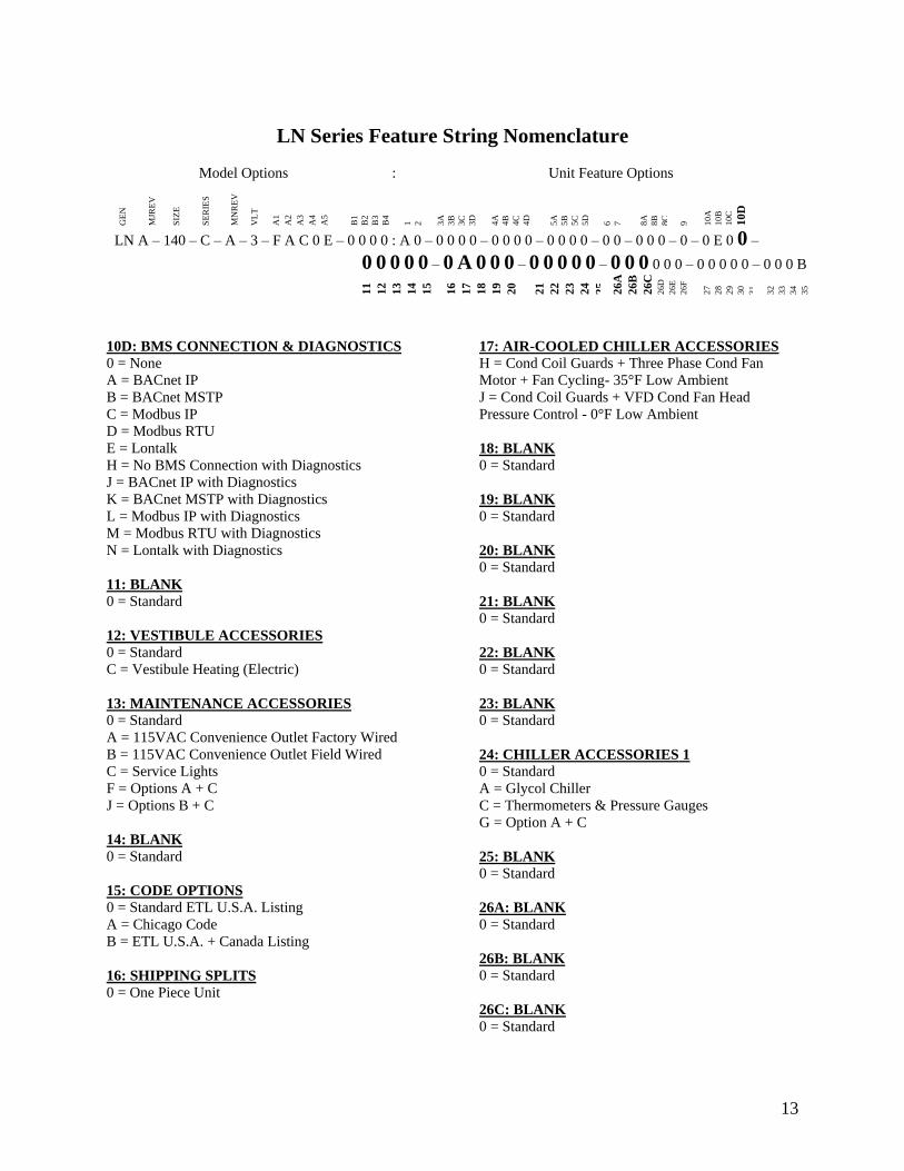
13
LN Series Feature String Nomenclature
Model Options Unit Feature Options
GE
N
MJR
EV
S
IZE
SE
RIE
S
MN
RE
V
VL
T
A1
A2
A3
A4
A5
B1
B2
B3
B4
1
2
3A
3B
3C
3D
4A
4B
4C
4D
5A
5B
5C
5D
6
7
8A
8B
8C
9
10A
10B
10C
10
D
LN A ndash 140 ndash C ndash A ndash 3 ndash F A C 0 E ndash 0 0 0 0 A 0 ndash 0 0 0 0 ndash 0 0 0 0 ndash 0 0 0 0 ndash 0 0 ndash 0 0 0 ndash 0 ndash 0 E 0 0 ndash
0 0 0 0 0 ndash 0 A 0 0 0 ndash 0 0 0 0 0 ndash 0 0 0 0 0 0 ndash 0 0 0 0 0 ndash 0 0 0 B
11
12
13
14
15
16
17
18
19
20
21
22
23
24
25
26
A
26
B
26
C
26D
26E
26F
27
28
29
30
31
32
33
34
35
10D BMS CONNECTION amp DIAGNOSTICS
0 = None
A = BACnet IP
B = BACnet MSTP
C = Modbus IP
D = Modbus RTU
E = Lontalk
H = No BMS Connection with Diagnostics
J = BACnet IP with Diagnostics
K = BACnet MSTP with Diagnostics
L = Modbus IP with Diagnostics
M = Modbus RTU with Diagnostics
N = Lontalk with Diagnostics
11 BLANK
0 = Standard
12 VESTIBULE ACCESSORIES
0 = Standard
C = Vestibule Heating (Electric)
13 MAINTENANCE ACCESSORIES
0 = Standard
A = 115VAC Convenience Outlet Factory Wired
B = 115VAC Convenience Outlet Field Wired
C = Service Lights
F = Options A + C
J = Options B + C
14 BLANK
0 = Standard
15 CODE OPTIONS
0 = Standard ETL USA Listing
A = Chicago Code
B = ETL USA + Canada Listing
16 SHIPPING SPLITS
0 = One Piece Unit
17 AIR-COOLED CHILLER ACCESSORIES
H = Cond Coil Guards + Three Phase Cond Fan
Motor + Fan Cycling- 35degF Low Ambient
J = Cond Coil Guards + VFD Cond Fan Head
Pressure Control - 0degF Low Ambient
18 BLANK
0 = Standard
19 BLANK
0 = Standard
20 BLANK
0 = Standard
21 BLANK
0 = Standard
22 BLANK
0 = Standard
23 BLANK
0 = Standard
24 CHILLER ACCESSORIES 1
0 = Standard
A = Glycol Chiller
C = Thermometers amp Pressure Gauges
G = Option A + C
25 BLANK
0 = Standard
26A BLANK
0 = Standard
26B BLANK
0 = Standard
26C BLANK
0 = Standard
14
LN Series Feature String Nomenclature
Model Options Unit Feature Options
GE
N
MJR
EV
S
IZE
SE
RIE
S
MN
RE
V
VL
T
A1
A2
A3
A4
A5
B1
B2
B3
B4
1
2
3A
3B
3C
3D
4A
4B
4C
4D
5A
5B
5C
5D
6
7
8A
8B
8C
9
10A
10B
10C
10D
LN A ndash 140 ndash C ndash A ndash 3 ndash F A C 0 E ndash 0 0 0 0 A 0 ndash 0 0 0 0 ndash 0 0 0 0 ndash 0 0 0 0 ndash 0 0 ndash 0 0 0 ndash 0 ndash 0 E 0 0 ndash
0 0 0 0 0 ndash 0 A 0 0 0 ndash 0 0 0 0 0 ndash 0 0 0 0 0 0 ndash 0 0 0 0 0 ndash 0 0 0 B
11
12
13
14
15
16
17
18
19
20
21
22
23
24
25
26A
26B
26C
26
D
26
E
26
F
27
28
29
30
31
3
2
33
34
35
26D BLANK
0 = Standard
26E BLANK
0 = Standard
26F BLANK
0 = Standard
27 BLANK
0 = Standard
28 BLANK
0 = Standard
29 BLANK
0 = Standard
30 BLANK
0 = Standard
31 BLANK
0 = Standard
32 BLANK
0 = Standard
33 WARRANTY
0 = Standard Warranty
D = Compressor Warranty Years 2-5
34 CABINET MATERIAL
0 = Standard - Double Wall + R-13 Foam Insulation
35 PAINT amp SPECIAL PRICING
AUTHORIZATIONS
B = Premium AAON Gray Paint Exterior
E = Premium AAON Gray Paint Exterior + Shrink
Wrap
X = Special Pricing Authorization + Premium AAON
Gray Paint Exterior
1 = SPA + Premium AAON Gray Paint Exterior +
Shrink Wrap
4 = Special Pricing Authorization + Special Exterior
Paint Color
7 = SPA + Special Exterior Paint Color + Shrink
Wrap
15
General Information
AAON LN Series chillers are complete self-
contained liquid chilling units They are
assembled wired charged and run-tested
Models are available for air-cooled
applications Chiller primary pumping
packages are available as optional features
Codes and Ordinances
LN Series units have been tested and
certified by ETL in accordance with UL
Safety Standard 1995CSA C222 No 236
System should be sized in accordance with
the American Society of Heating
Refrigeration and Air Conditioning
Engineers Handbook
Installation of LN Series units must conform
to the ICC standards of the International
Mechanical Code the International Building
Code and local building plumbing and
waste water codes All appliances must be
electrically grounded in accordance with
local codes or in the absence of local codes
the current National Electric Code
ANSINFPA 70 or the current Canadian
Electrical Code CSA C221
Receiving Unit
When received the unit should be checked
for damage that might have occurred in
transit If damage is found it should be noted
on the carrierrsquos Freight Bill A request for
inspection by carrierrsquos agent should be made
in writing at once Nameplate should be
checked to ensure the correct model sizes and
voltages have been received to match the job
requirements
If repairs must be made to damaged goods
then the factory should be notified before any
repair action is taken in order to protect the
warranty Certain equipment alteration
repair and manipulation of equipment
without the manufacturerrsquos consent may void
the product warranty Contact AAON
Technical Support for assistance with
Improper installation adjustment alteration service or maintenance can cause property damage personal injury or loss of life Startup and service must be performed by a Factory Trained Service Technician
WARNING
The Clean Air Act of 1990 bans the intentional venting of refrigerant as of July 1 1992 Approved methods of recovery recycling or reclaiming must be followed
CAUTION
Coils and sheet metal surfaces present sharp edges and care must be taken when working with equipment
Failure to observe the following instructions will result in premature failure of your system and possible voiding of the warranty
WARNING
WARNING
16
handling damaged goods repairs and freight
claims (918) 382-6450
Storage
If installation will not occur immediately
following delivery store equipment in a dry
protected area away from construction traffic
and in the proper orientation as marked on the
packaging with all internal packaging in
place Secure all loose-shipped items
Chiller
Failure to observe the following instructions
will result in premature failure of your
system and possible voiding of the warranty
Never turn off the main power supply to the
unit except for complete shutdown When
power is cut off from the unit any
compressors using crankcase heaters cannot
prevent refrigerant migration This means the
compressor will cool down and liquid
refrigerant may accumulate in the
compressor The compressor is designed to
pump refrigerant gas and damage may occur
when power is restored if liquid enters the
compressor
Before unit operation the main power switch
must be turned on for at least 24 hours for
units with compressor crankcase heaters
This will give the crankcase heater time to
clear any liquid accumulation out of the
compressor before it is required to run
Rotation must be checked on all MOTORS AND COMPRESSORS of three phase units All motors to include and not be limited to pump motors and condenser fan motors should all be checked by a qualified service technician at startup and any wiring alteration should only be made at the unit power connection
CAUTION
Scroll compressors are directional and will be damaged by operation in the wrong direction Low pressure switches on compressors have been disconnected after factory testing Rotation should be checked by a qualified service technician at startup using suction and discharge pressure gauges and any wiring alteration should only be made at the unit power connection
CAUTION
CRANKCASE HEATER OPERATION
Units may be equipped with compressor crankcase heaters which should be energized at least 24 hours prior to cooling operation to clear any liquid refrigerant from the compressors
CAUTION
COMPRESSOR CYCLING
3 MINUTE MINIMUM OFF TIME To prevent motor overheating compressors must cycle off for a minimum of 3 minutes
3 MINUTE MINIMUM ON TIME To maintain the proper oil level compressors must cycle on for a minimum of 3 minutes The cycle rate must not exceed 6 starts per hour
WARNING
17
Never cut off the main power supply to the
unit except for complete shutdown Always
control the system from the building
management system or control panel never
at the main power supply (except for
emergency or for complete shutdown of the
system)
Scroll compressors must be on a minimum of
3 minutes and off for a minimum of 3
minutes The cycle rate must be no more than
6 starts per hour
The chiller is furnished with a pressure
differential switch that is factory installed
between the chilled water supply and return
connections This sensor must not be
bypassed since it provides a signal to the unit
controller that water flow is present in the
heat exchanger and the unit can operate
without the danger of freezing the liquid
Compressor life will be seriously shortened
by reduced lubrication and the pumping of
excessive amounts of liquid oil and liquid
refrigerant
Wiring Diagrams
A complete set of unit specific wiring
diagrams in both ladder and point-to-point
form are laminated in plastic and located
inside the control compartment door
General Maintenance
When the initial startup is made and on a
periodic schedule during operation it is
necessary to perform routine service checks
on the performance of the chiller This
includes reading and recording suction
pressures and checking for normal sub-
cooling and superheat See the air-cooled
condenser sections in this manual for specific
details
Chiller Primary Pumping
Primary pumping uses a single pump to move
water (or glycol) through the chiller barrel
and back to the building This pumping
package provides a constant or variable flow
of water to the system The pump is activated
whenever the chiller is given a run signal
Water enters the unit through the return water
piping and then travels through an air
separator to remove any air that is entrapped
in the water Following this the water flows
through a suction guide with strainer The
end of the suction guide is removable for
strainer access The strainer assembly is
composed of two parts the operational
strainer and the startup strainer (located
inside the operational strainer) which is to be
removed 24 hours after startup
The pump is installed after the suction guide
and before a combination valve (Flo-Trex)
This combination valve acts as isolation
valve check valve and flow balancing valve
The shell and tube or brazed plate evaporator
is placed after the combination valve in the
water circuit with a flow switch installed
across its inlet and outlet This flow switch
closes when the velocity is above 07 feet per
second The closing flow switch signals the
control system to indicate flow through the
heat exchanger and allow cooling to activate
as required to maintain the setpoint The
water exiting the chiller evaporator leaves the
unit through the water out connection
18
Automatic Air Vent
There is an automatic air vent installed at the
high point of the system inside the pumping
package compartment The air vent valve
must be in the proper position for operation
Ensure that the small vent cap is loosened two
turns from the closed position allowing air to
be vented from the system It is advisable to
leave the cap on to prevent impurities from
entering the valve See appendix for
additional information
Dual Pumps
When redundant pumping is required factory
installed dual pumps can be ordered A dual
pump is a pump with two independent motors
and pumps in a single casing This dual pump
has a swing split-flapper valve in the
discharge port to prevent liquid recirculation
when only one pump is operating Isolation
valves in the casing allow one pump to be
isolated and removed for service while the
other pump is still operating
The controls package will activate the pump
when the unit is given a run command If the
controls do not recognize flow in 60 seconds
the second pump will be activated and an
alarm signal will be generated If the second
pump does not activate the cooling will be
locked out See appendix for additional
information
Pressure Gauges and Thermometers
Pressure gauges and thermometers are
available as a factory installed option
Thermometers are installed on the inlet and
outlet of the unit One pressure gauge is
installed at each pump This pressure gauge
is connected in three places to the water
piping before the suction guidestrainer after
the suction guide and before the pump and
after the pump There is also a needle valve
at each of these points to isolate the pressure
To measure the pressure at any given point
open the needle valve at that point and close
the other two needle valves One gauge is
used so that the calibration of the pressure
gauge is irrelevant in the calculation of the
differential pressure
Pipe Insulation
The water piping and components on units
with pumping packages are not insulated at
the factory Insulation should be installed on
the water piping after the system has been
checked for leaks
19
Installation
Chiller Placement
The AAON LN Series is designed for
outdoor applications and mounting at ground
level or on a rooftop It must be placed on a
level and solid foundation that has been
prepared to support its weight
The placement relative to the building air
intakes and other structures must be carefully
selected Be sure to observe the dimensions
that are on the rating plate of the chiller for
operational and service clearances
Table 1 - Service Clearances
Location Unit Size
45-140 tons
Front -
(Controls Side) 72rdquo
Back 72rdquo
Ends 96rdquo
Top Unobstructed
Condenser coils and fans must be free of any
obstructions in order to start and operate
properly with a correct amount of airflow
For proper unit operation the immediate area
around condenser must remain free of debris
that may be drawn in and obstruct airflow in
the condensing section
Consideration must be given to obstruction
caused by snow accumulation when placing
the unit
Curb and Steel Mount Installation
Make openings in the roof decking large
enough to allow for water piping electrical
penetrations and workspace only Do not
make openings larger than necessary Set the
curb to coincide with the openings Make
sure curb is level
If the LN is installed on a curb use a curb cap
for the open area under the condenser section
Unit specific curb drawing is included with
job submittal See SMACNA Architectural
Sheet Metal Manual for curb installation
details
Units require rail support along all four sides
of the unit base
When installed at ground level a one-piece
concrete slab should be used with footings
that extend below the frost line Care must
also be taken to protect the coil and fins from
damage due to vandalism or other causes
If unit is elevated a field supplied catwalk is
recommended to allow access to unit service
doors
This unit ships with a curb gasket that is 1frac14rdquo
wide and 1frac12rdquo tall It is recommended that this
or another similar gasket be used between the
curb and the unit to reduce vibration from the
unit to the building
All roofing work should be performed by competent roofing contractors to avoid any possible leakage
CAUTION
Figure 1 - LN Base
20
Figure 2 - Curb Mounting with Dimensions
Figure 3 - Steel Mounting Rail with
Dimensions
Table 2 - Mounting Dimensions
Tons A B C D
45-140 142rdquo 138rdquo 134rdquo 139rdquo
Figure 2
Figure 3
Lifting and Handling
If cables or chains are used to hoist the unit
they must be the same length and care should
be taken to prevent damage to the cabinet
See Figure 5 and Figure 6 for additional
information
Before lifting unit be sure that all shipping
material has been removed from unit Secure
hooks and cables at all lifting points lugs
provided on the unit
Hoist unit to a point directly above the curb
or mounting rail Be sure that the gasket
material has been applied to the curb or
mounting rail
Carefully lower and align unit with utility and
duct openings Lower the unit until the unit
skirt fits around the curb Make sure the unit
is properly seated on the curb and is level
Figure 4 - Lifting Points
21
Figure 5 - Lifting Detail of a 45-60 ton Unit
Figure 6 - Lifting Detail of a 75-140 ton Unit
Lifting slot locations are unit specific
Unit must be rigged at all marked lifting points
22
Water Connection
Connect the supply and return water lines
The connection size is listed on the unit rating
sheet along with the designed volumetric
flow rate The maximum operating pressure
for AAON LN Series units is 125 psi
Mounting Isolation
For roof mounted applications or anytime
vibration transmission is a factor vibration
isolators may be used
Access Doors
Lockable access door is provided to the
compressor and control compartment A
separate access door is also provided to the
pumping package compartment
A light switch with service lights is provided
on the wall of the compressor and control
compartment
End Flashing Installation
On all LN Series units the cabinet width will
overhang the shipping trailer on each side
In order to secure and protect the unit during
transit the sheet metal end flashings have
been removed from the unit The slot created
at the base of each end of the unit allows the
unit to set firmly on the trailer deck
Sheet metal flashings are shipped loose with
the unit and once the unit is set into place the
flashings must be installed on each end of the
unit to complete the finished seal at the base
The flashings are unit specific and designed
to cover the slot at each end of the unit to
prevent water run-off into the curb
Failure to attach and seal the end of unit with
the flashings may result in water leakage into
the curb
Figure 7 - Factory Supplied End Flashings
PVC (Polyvinyl Chloride) and CPVC (Chlorinated Polyvinyl Chloride) are vulnerable to attack by certain chemicals Polyolester (POE) oils used with R-410A and other refrigerants even in trace amounts in a PVC or CPVC piping system will result in stress cracking of the piping and fittings and complete piping system failure
CAUTION
The chiller must be operated only with liquid flowing through the evaporators
WARNING
Installing Contractor is responsible for proper sealing of the water piping entries into the unit Failure to seal the entries may result in damage to the unit and property
CAUTION
23
Low Ambient Operation
If the chiller is ordered for a Low Ambient
application the liquid system must use a
glycol solution and the piping must be
insulated to be prepared for freezing
conditions Care must be taken in the source
of electrical power for the heating tape and
thermostat
Electrical
The single point electrical power connections
are made in the electrical control
compartment
The microprocessor control furnished with
the unit is supplied with its own power supply
factory wired to the main power of the
outdoor mechanical room
Verify the unit nameplate voltage agrees with
the power supply Connect power and control
field wiring as shown on the unit specific
wiring diagram provided with the unit
Size supply conductors based on the unit
MCA rating Supply conductors must be
rated a minimum of 167degF (75degC)
Route power and control wiring separately
through the utility entry Do not run power
and signal wires in the same conduit
Protect the branch circuit in accordance with
code requirements The unit must be
electrically grounded in accordance with
local codes or in the absence of local codes
the current National Electric Code
ANSINFPA 70 or the current Canadian
Electrical Code CSA C221
Power wiring is to the unit terminal block or
main disconnect All wiring beyond this point
has been done by the manufacturer and
cannot be modified without effecting the
units agencysafety certification
Figure 8 - Front View of Utility Entry and
Power Switch from Control Compartment
Electric shock hazard Before attempting to perform any installation service or maintenance shut off all electrical power to the unit at the disconnect switches Unit may have multiple power supplies Failure to disconnect power could result in dangerous operation serious injury death or property damage
WARNING
In order to prevent water leakage into the roof curb the factory provided sheet metal flashings MUST BE attached to the unit base to cover the shipping slots at both ends of the unit
CAUTION
24
Startup technician must check for proper
motor rotation and check fan motor amperage
listed on the motor nameplate is not
exceeded Motor overload protection may be
a function of the variable frequency drive and
must not be bypassed
Note All units are factory wired for
208230V 460V or 575V If unit is to be
connected to a 208V supply the transformer
must be rewired to 208V service For 208V
service interchange the yellow and red
conductor on the low voltage control
transformer
Red-Black for 208V
Yellow-Black for 230V
Wire control signals to the unitrsquos low voltage
terminal block located in the controls
compartment All wiring beyond this point
has been completed by the manufacturer and
cannot be modified without effecting the
unitrsquos agencysafety certification
If any factory installed wiring must be
replaced use a minimum 221degF (105degC) type
AWM insulated conductors
Supply voltage must be within the minmax
range shown on the unit nameplate Available
short circuit current should not exceed the
short circuit current rating (SCCR) shown on
the unit nameplate
Three phase voltage imbalance will cause
motor overheating and premature failure
The maximum allowable imbalance is 5
Voltage imbalance is defined as 100 times the
maximum deviation from the average voltage
divided by the average voltage
Example
(218V+237V+235V)3 = 230V then
100(230V-218V)230V = 52 which
exceeds the allowable imbalance
Check voltage imbalance at the unit
disconnect switch and at the compressor
terminal Contact your local power company
for line voltage corrections
Three phase voltage imbalance will cause motor overheating and premature failure
CAUTION
Scroll compressors are directional and will be damaged by operation in the wrong direction Low pressure switches on compressors have been disconnected after factory testing Rotation should be checked by a qualified service technician at startup using suction and discharge pressure gauges and any wiring alteration should only be made at the unit power connection
Installing Contractor is responsible for proper sealing of the electrical and gas entries into the unit Failure to seal the entries may result in damage to the unit and property
CAUTION CAUTION
25
Variable Speed Compressors
Variable speed compressors should not be
operated outside the factory determined
frequency range The factory determined
compressor VFD frequency range is given
below in Table 3
Table 3- Tandem Circuited Variable Speed
Compressor VFD Frequency Range
Model (LN-) Compressor VFD
Range (Hz)
208V 230V 460V and 575V Units
045 055 060 45-65Hz
075 45-70Hz
095 105 120 35-60 Hz
140 35-65 Hz
No variable speed compressor shall operate below 35 Hz Operating variable speed compressors outside the frequency range specified in this manual voids all warranties and may result in compressor failure
CAUTION
Rotation must be checked on all MOTORS AND COMPRESSORS of three phase units Condenser fan motors should all be checked by a qualified service technician at startup and any wiring alteration should only be made at the unit power connection Variable frequency drives are programmed to automatically rotate the fan in the correct rotation Do not rely on fans with variable frequency drives for compressor rotation
CAUTION
26
Startup (See back of the manual for startup form)
Before the startup of the chiller be sure that
the following items have been checked
1 Verify that electrical power is available to
the unit
2 Verify that any remote stopstart device
connected to the chiller controller is
requesting the chiller to start
3 Verify that liquid flow is present through
the chiller from the building
4 There should be a building load of at least
25 of the chiller capacity in order to
properly check operation
5 With the main power switch off review
the MCS Controller Manual provided
with the chiller Understand the keypad
functions how to set the leaving water
temperature setpoint and how to initiate
the Run State
Use the general check list at the top of the
startup form to make a last check that all the
components are in place water flow is
present and the power supply is energized
Using the controller keypad individually set
the outputs in ldquoManual Onrdquo to confirm relay
closure and compressor operation
Cycle through all the compressors to confirm
that all are operating within tolerance
While performing the check use the startup
form to record observations of compressor
amps and refrigerant pressures
When all is running properly place the
controller in the Run mode and observe the
system until it reaches a steady state of
operation
Note For more information on programming
the controller refer to the MCS Controller
manual provided with the chiller
Electric shock hazard Shut off all electrical power to the unit to avoid shock hazard or injury from rotating parts
WARNING
Improper installation adjustment alteration service or maintenance can cause property damage personal injury or loss of life Startup and service must be performed by a Factory Trained Service Technician
WARNING
Rotation must be checked on all MOTORS AND COMPRESSORS of three phase units All motors to include and not be limited to pump motors and condenser fan motors should all be checked by a qualified service technician at startup and any wiring alteration should only be made at the unit power connection
CAUTION
Before completing installation a complete operating cycle should be observed to verify that all components are functioning properly
CAUTION
27
Axial Flow Condenser Fans
Multi-Wing Z Series Aluminum Fan Blade
Pitch Angle Setting Instructions
1 Maintain the balance of fan
Mark the hub castings across a joint so the
fan hub can be reassembled in the same
orientation
Mark the location of any balancing weight
Balancing weight will be on the outer bolt
circle in the form of washers andor longer
bolts or an additional balancing nut
Number the blades and blade sockets so that
they are replaced into their original position
Figure 9 - Fan with the HUB on the top and
RET on the bottom
2 Determine the direction of rotation
Right R is clockwise when facing the
discharge side of the fan and Left L is
counterclockwise when facing the discharge
side of the fan
3 Determine the bushing mount location
The bushing mount is the center section of the
hub through which the fan is mounted to the
shaft and typically contains either setscrews
or a center-tapered hole where the bushing
inserts
Location A is with the bushing mount on air
inlet side of the fan
Location B is with the bushing mount on air
discharge side of the fan
Figure 10 - Bushing Mount Location
4 Determine the pin location groove
Disassemble fan on a flat surface and note in
which groove the pin is located
Figure 11 - RET with Pin in Groove 4
Bushing
Mount
A B Bushing
Mount
Bushing Bushing
1 2 3 4
28
5 Determine whether the pin is in the HUB
or RET
Figure 12 - Fan HUB and RET Castings
6 Determine the current blade pitch and the pin location for the new blades
Table 4 - ReturnExhaust Fan Pin Location
Type Bushing
Mount
Blade Pitch Angle
20deg 25deg 28deg 30deg 33deg 35deg 38deg 40deg 45deg 50deg
5Z A - RET - RET RET RET HUB HUB HUB HUB
B - HUB - HUB HUB HUB RET RET RET RET
Table 5 - ReturnExhaust Fan Pin Location
Type Rot Blade Pitch Angle
20deg 25deg 28deg 30deg 33deg 35deg 38deg 40deg 45deg 50deg
5Z R - 4 - 3 2 1 4 3 2 1
L - 1 - 2 3 4 1 2 3 4
7 Replace fan blades in the new pin
location and reassemble the fan
Replace the blades with the pin in the 1 2 3
or 4 groove position of either the HUB or
RET Assemble the fan making sure to place
the blades in their previous blade sockets to
match up the previous orientation of HUB
and RET and to replace any balancing
weights in their previous locations Tighten
bolts in a cross pattern to 5-6 ft-lbs of torque
29
Multi-Wing W Series Black Glass
Reinforced Polypropylene Fan Blade Pitch
Angle Setting Instructions
Contact the AAON parts department to
acquire the new pitch pins for the fan blades
Note original position of retaining plates
center boss and all hardware including
additional hardware used for balancing
1 Remove all the bolts and nuts
2 Determine blade rotation ndash on the concave
side of the blade is a blade marking showing
6WR 6WL 7WL 7WR or 9WR The ldquoLrdquo
and ldquoRrdquo denote the rotation of the blade
3 Replace the pitch insert in the blade root
with an insert of the desired pitch
Figure 13 - Pitch Insert
4 Replace blades to their original location
5 Replace all nuts bolts and washers on the
fan hub
6 Replace retaining plates and center boss to
original location
7 Tighten nuts and bolts to 14 ft-lbs of
torque
Fan Assembly Bushings
The fan assembly bushings should be
tightened to the specifications listed in the
following table
Table 6 - Fan Assembly Bushing Torque
Specifications
Bushing Tightening Torque
(in-lbs)
H X 1125 95
H X 1375 95
SH X 1125 108
SH X 1375 108
SD X 1125 108
SD X 1375 108
SD X 1625 108
SD X 1875 108
SK X 2125 180
30
Maintenance
General
Qualified technicians must perform routine
service checks and maintenance This
includes reading and recording the
condensing and suction pressures and
checking for normal sub-cooling and
superheat
Air-cooled chillers require maintenance
schedulesprocedures Unit specific
instructions are included in this manual
Compressors
The scroll compressors are fully hermetic and
require no maintenance except keeping the
shell clean
Refrigerant Suction Line Filter
Each refrigerant circuit contains a
replaceable core suction line filter One
month after start-up remove the filter
element
The replaceable core suction filters are
provided with pressure taps and shutoff
valves for isolation when removing the filter
For safety purposes a service manifold must
be attached prior to filter maintenance
Suction Filter Removal Instructions
1 Shut down operation of the unit
2 Close both shut-off valves to isolate
the suction filter
3 Reclaim the refrigerant from the
suction filter section
4 Remove the bolts from the suction
filter end plate
5 Remove the pleated filter assembly
Prior to filter core service a service manifold MUST BE attached to in and out pressure connections to assure no pressure exists during filter maintenance Non-compliance could result in injury or violation of EPA regulations
Service gauges MUST BE connected before operating the isolation valves for the replaceable core filter
WARNING
WARNING
31
6 Replace the suction filter end plate
and bolts
7 Evacuate the suction filter assembly
to 500 microns
8 Open both shut-off valves
Adjusting Refrigerant Charge
All AAON chillers are shipped with a full
factory charge Periodically adjusting the
charge of a system may be required
Adjusting the charge of a system in the field
must be based on determination of liquid sub-
cooling and evaporator superheat On a
system with an expansion valve liquid sub-
cooling is more representative of the charge
than evaporator superheat but both
measurements must be taken
Before Charging
Refer to the unit nameplate as a reference
when determining the proper refrigerant
charge
Unit being charged must be at or near full
load conditions before adjusting the charge
Units equipped with hot gas bypass must
have the hot gas bypass valve closed to get
the proper charge
After adding or removing charge the system
must be allowed to stabilize typically 10-15
minutes before making any other
adjustments
The type of unit and options determine the
ranges for liquid sub-cooling and evaporator
superheat Refer to Table 7 when determining
the proper sub-cooling
For units equipped with low ambient (0degF)
option see the special charging instructions at
the end of this section
Checking Liquid Sub-cooling
Measure the temperature of the liquid line as
it leaves the condenser coil
Read the gauge pressure at the liquid line
close to the point where the temperature was
taken You must use liquid line pressure as it
will vary from discharge pressure due to
condenser coil pressure drop
Convert the pressure obtained to a saturated
temperature using the appropriate refrigerant
temperature-pressure chart
Subtract the measured liquid line temperature
from the saturated temperature to determine
the liquid sub-cooling
Compare calculated sub-cooling to the table
below for the appropriate unit type and
options
The Clean Air Act of 1990 bans the intentional venting of refrigerant (CFCrsquos and HCFCrsquos) as of July 1 1992 Approved methods of recovery recycling or reclaiming must be followed Fines andor incarceration may be levied for non-compliance
CAUTION
Polyolester (POE) and Polyvinylether (PVE) oils are two types of lubricants used in hydrofluorocarbon (HFC) refrigeration systems Refer to the compressor label for the proper compressor lubricant type
CAUTION
32
Checking Evaporator Superheat
Measure the temperature of the suction line
close to the compressor
Read gauge pressure at the suction line close
to the compressor
Convert the pressure obtained to a saturated
temperature using the appropriate refrigerant
temperature-pressure chart
Subtract the saturated temperature from the
measured suction line temperature to
determine the evaporator superheat
For refrigeration systems with tandem scroll
compressors it is critical that the suction
superheat setpoint on the expansion valve is
set with one compressor running The suction
superheat should be 10-13degF with one
compressor running The suction superheat
will increase with both compressors in a
tandem running Inadequate suction
superheat can allow liquid refrigerant to
return to the compressors which will wash the
oil out of the compressor Lack of oil
lubrication will destroy a compressor Liquid
sub-cooling should be measured with both
compressors in a refrigeration system
running
Compare calculated superheat to Table 7 for
the appropriate unit type and options
Table 7 - Acceptable Refrigeration Circuit
Values
Air-Cooled Chiller with Scroll
Compressors
Sub-Cooling2 12-18degF
Superheat1 10-15degF 1 One compressor running in tandem 2 Two compressors running in tandem
Adjusting Sub-cooling and Superheat
Temperatures
The system is overcharged if the sub-cooling
temperature is too high and the evaporator is
fully loaded (low loads on the evaporator
result in increased sub-cooling) and the
evaporator superheat is within the
temperature range as shown in Table 7 (high
superheat results in increased sub-cooling)
Correct an overcharged system by reducing
the amount of refrigerant in the system to
lower the sub-cooling
The system is undercharged if the superheat
is too high and the sub-cooling is too low
Correct an undercharged system by adding
refrigerant to the system to reduce superheat
and raise sub-cooling
If the sub-cooling is correct and the superheat
is too high the expansion valve may need
adjustment to correct the superheat
Expansion valves must be adjusted to approximately 10-15degF of suction superheat Failure to have sufficient superheat will damage the compressor and void the warranty
CAUTION
DO NOT OVERCHARGE Refrigerant overcharging leads to excess refrigerant in the condenser coils resulting in elevated compressor discharge pressure
CAUTION
33
Table 8 - R-410A Refrigerant Temperature-Pressure Chart
F psig F psig F psig F psig F psig
20 783 50 1422 80 2349 110 3641 140 5401
21 800 51 1448 81 2386 111 3691 141 5470
22 818 52 1474 82 2423 112 3742 142 5539
23 836 53 1501 83 2460 113 3794 143 5609
24 854 54 1528 84 2498 114 3846 144 5679
25 872 55 1555 85 2537 115 3899 145 5751
26 891 56 1582 86 2575 116 3952 146 5823
27 910 57 1610 87 2614 117 4005 147 5896
28 929 58 1638 88 2654 118 4059 148 5969
29 949 59 1667 89 2694 119 4114 149 6044
30 968 60 1696 90 2735 120 4169 150 6119
31 988 61 1725 91 2776 121 4225
32 1009 62 1754 92 2817 122 4282
33 1029 63 1784 93 2859 123 4339
34 1050 64 1815 94 2901 124 4396
35 1071 65 1845 95 2944 125 4454
36 1092 66 1876 96 2987 126 4513
37 1114 67 1907 97 3030 127 4573
38 1136 68 1939 98 3075 128 4632
39 1158 69 1971 99 3119 129 4693
40 1181 70 2004 100 3164 130 4754
41 1203 71 2036 101 3210 131 4816
42 1227 72 2070 102 3256 132 4878
43 1250 73 2103 103 3302 133 4941
44 1274 74 2137 104 3349 134 5005
45 1298 75 2171 105 3396 135 5069
46 1322 76 2206 106 3444 136 5134
47 1347 77 2241 107 3493 137 5200
48 1372 78 2277 108 3542 138 5266
49 1397 79 2313 109 3591 139 5333
34
Lubrication
All original motors and bearings are
furnished with an original factory charge of
lubrication Certain applications require
bearings be re-lubricated periodically The
schedule will vary depending on operating
duty temperature variations or severe
atmospheric conditions
Bearings should be re-lubricated at normal
operating temperatures but not when
running
Rotate the fan shaft by hand and add only
enough grease to purge the seals DO NOT
OVERLUBRICATE
Air-Cooled Condenser
The air-cooled condenser section rejects heat
by passing outdoor air over the fin tube coils
for cooling of the hot refrigerant gas from the
compressors The heated air will discharge
from the top of the section through the axial
flow fans
The condenser coils should be inspected
yearly to ensure unrestricted airflow If the
installation has a large amount of airborne
dust or other material the condenser coils
should be cleaned according to the
microchannel coil cleaning section
Brazed Plate Heat Exchanger Cleaning
Because of a normally high degree of
turbulence in brazed plate heat exchangers
for many applications the heat exchanger
channels are self-cleaning For applications
that are not self-cleaning (ie hard water at
high temperatures etc) or applications where
additional cleaning is desired it is possible to
clean the brazed plate heat exchanger by
circulating a cleaning liquid
Use a tank with weak acid 5 phosphoric
acid (H3PO4) or if the exchanger is
frequently cleaned 5 oxalic acid (H2C2O4)
Pump the cleaning liquid through the
exchanger For optimum cleaning the
cleaning solution flow rate should be a
minimum of 15 times the normal flow rate
preferably in a back-flush mode After
cleaning the heat exchanger must be rinsed
with clean water A solution of 1-2 sodium
hydroxide (NaOH) or sodium bicarbonate
(NaHCO) before the last rinse ensures that all
acid is neutralized
E-Coated Coil Cleaning
Documented quarterly cleaning of e-coated
coils is required to maintain coating warranty
coverage
Surface loaded fibers or dirt should be
removed prior to water rinse to prevent
restriction of airflow If unable to back wash
the side of the coil opposite of the coils
entering air side then surface loaded fibers or
dirt should be removed with a vacuum
cleaner If a vacuum cleaner is not available
a soft non-metallic bristle brush may be used
In either case the tool should be applied in
the direction of the fins Coil surfaces can be
easily damaged (fin edges bent over) if the
tool is applied across the fins
Use of a water stream such as a garden hose
against a surface loaded coil will drive the
fibers dirt and salts into the coil This will
make cleaning efforts more difficult Surface
loaded fibers must be completely removed
prior to using low velocity clean water rinse
Electric shock hazard Shut off all electrical power to the unit to avoid shock hazard or injury from rotating parts
WARNING
35
Quarterly cleaning is required to maintain
warranty coverage and is essential to
maintain the life of an E-coated coil Coil
cleaning shall be part of the units regularly
scheduled maintenance procedures
Failure to clean an E-coated coil on the
prescribed quarterly cycle will void the
warranty and may result in reduced
efficiency and durability in the environment
A routine two-step quarterly coil cleaning is
required to maintain warranty
Step one is to clean the coil with the below
approved coil cleaner (see approved products
list under the Recommended Coil Cleanersrdquo
section
Step two is to use the approved saltchloride
remover under the Recommended Chloride
Removerrdquo section to dissolve soluble salts
and revitalize the unit It is very important
when cleaning andor rinsing not to exceed
130degF and potable water pressure is less than
100 psig to avoid damaging the unit and coil
fin edges
For routine quarterly cleaning first clean the
coil with the below approved coil
cleaner After cleaning the coils with the
approved cleaning agent use the approved
chloride remover to remove soluble salts and
revitalize the unit
Recommended Coil Cleaner ndash Step 1
GulfCoatTM Coil Cleaner assuming it is
used in accordance with the manufacturers
directions on the container for proper mixing
and cleaning has been approved for use on
E-coated coils to remove mold mildew dust
soot greasy residue lint and other
particulate Never use any cleaners that are
not approved
Recommended Chloride Remover ndash Step 2
CHLORRIDreg Concentrate assuming it
is used in accordance with the manufacturers
directions on the container for proper mixing
has been approved for use on E-coated coils
to remove chloridessalts amp sulfates Never
use any chloride removers that are not
approved
Warranty Protection ndash Step 1
Complete the coil cleaning following these
steps
1 Ensure that the power to the unit is off
and locked out
2 Clean the area around the unit if
needed to ensure leaves grass or
High velocity water from a pressure washer or compressed air should only be used at a very low pressure to prevent fin andor coil damages The force of the water or air jet may bend the fin edges and increase airside pressure drop Reduced unit performance or nuisance unit shutdowns may occur
Harsh chemicals household bleach or acid cleaners should not be used to clean e-coated coils These cleaners can be very difficult to rinse out of the coil and can accelerate corrosion and attack the e-coating If there is dirt below the surface of the coil use the recommended coil cleaners
CAUTION
CAUTION
36
loose debris will not be blown into the
coil
3 Remove panels or tops as required
gaining access to the coil(s) to be
cleaned
4 Using a pump up sprayer fill to the
appropriate level with potable water
and add the correct amount of
approved cleaner as per manufacture
instructions leaving room for the
pump plunger to be reinserted
NOTE Coils should always be cleaned
back flushed opposite of airflow to prevent
impacting the dirt into the coil
5 If the coils have heavy dirt fibers
grass leaves etc on the interior or
exterior face areas a vacuum and
brush should be used to remove those
surface contaminants prior to
applying cleaner The interior floor
drain tray or pan areas should also be
vacuumed
6 Apply the mixed cleaner to coil
surfaces using a pressurized pump up
sprayer maintaining a good rate of
pressure and at a medium size nozzle
spray (not a solid stream and not a
wide fan but somewhere in the
middle) Work in sectionspanels
ensuring that all areas are covered and
kept wetted
7 Apply the cleaner to unit interior air
exiting side coil surfaces first Work
in sectionspanels moving side to side
and from top to bottom
8 Generously soak coils by spraying
cleaner directly on and into the fin
pack section to be cleaned and allow
the cleaning solution to soak for 5 to
10 minutes
9 Using pressurized potable water
(lt100 psi) rinse the coils and
continue to always work in
sectionspanels Start at the top of the
coil and slowly move vertically
downward to the bottom Then
staying in the same vertical area
slowly move back up to the top where
you started Now move over slightly
overlapping the area just completed
and repeat above Continue until all
coil areas on the inside of the unit
have been rinsed
10 Complete steps 5-9 for the exterior air
entering side of the coils
11 Final rinse ndash Now complete a quick
rinse of both sides of the coil
including the headers piping u-
bends and hairpins
12 If the coil has a drain pan or unit floor
that is holding rinse water or cleaner
extra time and attention will need to
be taken in those areas to ensure a
proper rinse has been completed
Warranty Protection ndash Step 2
Complete the coil chloride (salt) removal
following these steps
1 CHLORRIDreg is a concentrate to be
used for both normal inland
applications at a 1001 mix ratio OR
for severe coastal applications 501
mix ratio with potable water (256
ounces of Chlorrid to 1 gal of water)
Using a pump up sprayer fill to the
appropriate level with potable water
and add the correct amount of
CHLORRIDreg salt remover leaving
room for the pump plunger to be
reinserted
2 Apply CHLORRIDreg to all external
coil surfaces using a pressurized
pump up sprayer maintaining a good
rate of pressure and at a medium size
nozzle spray (not a solid stream and
not a wide fan but somewhere in the
middle) Work in sectionspanels
ensuring that all areas are covered and
kept wetted
37
3 Generously soak coils by spraying
CHLORRIDreg directly on and into
the fin pack section Let stand for 5 to
10 minutes keeping the area wetted
Do not allow to dry before rinsing
4 Using pressurized potable water
(lt100 psi) rinse the CHLORRIDreg
and dissolved chloridessalts off of
the coils continuing to always work in
sectionspanels
5 Starting at the top of the coil begin
rinsing the coil from side to side until
you reach the bottom Repeat as many
times as is necessary to ensure all coil
sectionspanels have been completed
and are thoroughly rinsed
6 Reinstall all panels and tops that were
removed
Microchannel Coil Cleaning
Documented routine cleaning of
microchannel coils with factory provided e-
coating is required to maintain coating
warranty coverage See E-Coated Coil
Cleaning section
Air-cooled heat exchangers may include
microchannel coils
Cleaning microchannel coils is necessary in
all locations In some locations it may be
necessary to clean the coils more or less often
than recommended In general a condenser
coil should be cleaned at a minimum of once
a year In locations where there is commonly
debris or a condition that causes dirtgrease
build up it may be necessary to clean the coils
more often Proper procedure should be
followed at every cleaning interval Using
improper cleaning technique or incorrect
chemicals will result in coil damage system
performance fall off and potentially leaks
requiring coil replacement
Documented routine cleaning of
microchannel coils with factory provided e-
coating is required to maintain coating
warranty coverage Use the E-Coated Coil
Cleaning section for details on cleaning e-
coated coils
Field applied coil coatings are not
recommended with microchannel coils
Allowed Chemical Cleaners and Procedures
AAON recommends certain chemicals that
can be used to remove buildup of grime and
debris on the surface of microchannel coils
These chemicals have been tested for
performance and safety and are the only
chemicals that AAON will warrant as correct
for cleaning microchannel coils
There are three procedures that are outlined
below that will clean the coils effectively
without damage to the coils Use of any other
procedure or chemical may void the warranty
to the unit where the coil is installed With
all procedures make sure the unit is off
before starting
The water pressure used to clean should not
exceed 140 psi from no closer than 6 inches
from the coils and with the water aimed
perpendicular to the coils
Electric shock hazard Shut off all electrical power to the unit to avoid shock hazard or injury from rotating parts
WARNING
WARNING
38
1 Simple Green
Simple Green is available from AAON Parts
and Supply (Part T10701) and is
biodegradable with a neutral 65 pH
Recommendation is to use it at a 4 to 1 mix
Use the following procedure
1 Rinse the coil completely with water Use
a hard spray but be careful not to bend or
damage the fins A spray that is too hard
will bend the fins Spray from the fan side
of the coil
2 With a pump sprayer filled with a mix of
4 parts water to one part Simple Green
spray the air inlet face of the coil Be sure
to cover all areas of the face of the coil
3 Allow the coil to soak for 10-15 minutes
4 Rinse the coil with water as in step one
5 Repeat as necessary
2 Vinegar
This is standard white vinegar available in
gallons from most grocery stores It has a pH
of 2-3 so it is slightly acidic Use the
following procedure
1 Rinse the coil completely with water Use
a hard spray but be careful not to bend or
damage the fins A spray that is too hard
will bend the fins Spray from the fan side
of the coil
2 Use a pump sprayer filled with vinegar
(100) Spray from the face of the coil in
the same direction as the airflow Be sure
to cover all areas of the face of the coil
3 Allow the coil to soak for 10-15 minutes
4 Rinse the coil with water as in step one
5 Repeat as necessary
3 Water Flush
This procedure can be used when the only
material to cause the coil to need cleaning is
debris from plant material that has impinged
the coil face
1 Rinse the coil completely with water Use
a hard spray but be careful not to bend or
damage the fins A spray that is too hard
will bend the fins Spray from the fan side
of the coil
2 Spray and rinse the coil from the face
Application Examples
The three procedures can be used to clean
microchannel coils They will fit with the
application depending on the area In some
areas where the springsummer has a large
cottonwood bloom 3 might work fine if the
unit is installed on an office building and no
other environmental factors apply
When a unit is installed where the sprinkler
system has water being sprayed onto the
condenser coil you might have better results
using 2 Vinegar is slightly acidic and may
help with the calcium build up from drying
water This also works well when grease is
part of the inlet air to a condenser coil
Generally the best and broadest based
procedure is 1 The grease cutting effect of
the Simple Green is good for restaurant
applications
Other Coil Cleaners
There are many cleaners on the market for
condenser coils Before using any cleaner
that is not covered in this section you must
get written approval from the AAON
warranty and service department Use of
unapproved chemicals will void the
warranty
Use pressurized clean water with pressure not to exceed 140 psi Nozzle should be 6rdquo and 80deg to 90deg from coil face Failure to do so could result in coil damage
CAUTION
39
AAON testing has determined that unless a
chemical has a neutral pH (6-8) it should not
be used
Beware of any product that claims to be a
foaming cleaner The foam that is generated
is caused by a chemical reaction to the
aluminum fin material on tube and fin coils
and with the fin tube and coating material on
microchannel coils
Microchannel coils are robust in many ways
but like any component they must be treated
correctly This includes cleaning the coils
correctly to give optimal performance over
many years
Service
If the unit will not operate correctly and a
service company is required only a company
with service technicians qualified and
experienced in both refrigerant chillers and
air conditioning are permitted to service the
systems to keep warranties in effect If
assistance is required the service technician
must contact AAON
Replacement Parts
Parts for AAON equipment may be obtained
from your local AAON representative When
ordering parts reference the unit serial
number and part number
AAON Technical Support
2424 S Yukon Ave
Tulsa OK 74107
Ph (918) 382-6450
techsupportAAONcom
wwwAAONcom
Note Before calling technician should have
model and serial number of the unit available
for the service department to help answer
questions regarding the unit
40
Appendix - Water Piping Component Information
Automatic Air Vent Valves
Automatic Air Vent Valves provide
automatic air venting for hot or cold water
distribution systems These vents purge air
that may be in the water system
The vent valve utilizes a float to actuate the
valve plug which is located at the top of the
valve Once the air is displaced and the
system pressure is sustained the valve plug
seals and prevents any water from escaping
from the system
The float vent can also operate as an anti-
vacuum device since it will permit air to enter
the system when it must be drained It can
also be installed to permit the separation and
dispersal of air while fluid is actually
circulating in the system
Overview
Body and cover are brass construction
Air vent with silicone rubber seal
Impurities do not usually affect function
as maximum float line of water is always
lower than the valve seal
Float is high temperature resistant
polyethylene
Suitable for use with glycol systems
Can be disassembled for inspection and
cleaning
Operating Range
Minimum working pressure 145psi
(10 kPa)
Maximum working pressure 150psi
(10 bars)
Temperature Range 33degF ndash 240degF
(5degC ndash 116degC)
Performance
Performance curve details the quantity of air
vented by the ldquoFloat Ventrdquo according to the
pressure in the system
Note In order to get the best results in
venting air from risers use connecting pipes
41
of at least 1frasl2 diameter between the ldquoFloat
Ventrdquo valves and installation
Installation
When the air vent valve is installed as shown
the air will not be vented while the fluid is
circulating in the system but it can vent when
the system is shut off
The figure below shows the installation of the
vent valve for the venting of air while the
fluid is circulating in the system and the
required increase in pipe size in order to
obtain proper separation of air from water
The valve should be mounted only in a
vertical position as its operation is based on
the vertical movement of the float
While the air vent valve is in operation back
off the small vent cap two turns This is the
proper operating setting which will allow air
to be vented from the system It is advisable
to leave the cap on to prevent impurities from
entering the valve
Maintenance
No maintenance is normally necessary
However if the FV-4M1 is disassembled for
inspection or cleaning it is important that
when re-assembling to ensure that the spring
loaded lever properly engages under the float
collar
42
Dimensions ndash Weights
Pumps - Installation and Operating
Instructions
Introduction
This document contains specific information
regarding the safe installation operating and
maintenance of Vertical In-Line pumps and
should be read and understood by installing
operating and maintenance personnel The
equipment supplied has been designed and
constructed to be safe and without risk to
health and safety when properly installed
operated and maintained The instructions
following must be strictly adhered to If
clarification is needed on any point please
contact Armstrong quoting the equipment
serial number
Where under normal operating conditions the
limit of 68degC155degF (Restricted Zone) for
normal touch or 80degC176degF (Unrestricted
Zone) for unintentional touch may be
experienced steps should be taken to
minimize contact or warn operatorsusers that
normal operating conditions will be
exceeded In certain cases where the
temperature of the pumped liquid exceeds the
above stated temperature levels pump casing
temperatures may exceed 100degC212degF and
not withstanding pump insulation techniques
appropriate measures must be taken to
minimize risk for operating personnel
Storage
Pumps removed from service and stored
must be properly prepared to prevent
excessive rusting Pump port protection
plates must not be removed until the pump is
ready to connect to the piping Rotate the
shaft periodically (At least monthly) to keep
No Installation of this equipment should take place unless this document has been read and understood
CAUTION
43
rotating element free and bearings fully
functional
For long term storage the pump must be
placed in a vertical position in a dry
environment Internal rusting can be
prevented by removing the plugs at the top
and bottom of the casing and drain or air blow
out all water to prevent rust buildup or the
possibility of freezing Be sure to reinstall the
plugs when the unit is made operational
Rust-proofing or packing the casing with
moisture absorbing material and covering the
flanges is acceptable When returning to
service be sure to remove the drying agent
from the pump
Handling Large VIL Units
One effective way of lifting a large pumping
unit is to place lifting hooks through the
motor lifting rings or straps around the upper
part of the motor The pump and motor unit
will free-stand on the casing ribs Remove the
coupling guard and place (2) lifting straps
through the pumpmotor pedestal one on
each side of the motor shaft and secure to the
lifting device
With the straps in place using a spacer bar if
necessary to protect the motor fan cover the
whole assembly can now be lifted securely
Note Handling transportation and
installation of this equipment should only be
undertaken by trained personnel with proper
use of lifting equipment
Remove coupling guard and place lifting
straps on each side of coupling use spacer
bar if necessary to protect motor fan cover
Vertical Inline Pump Lifting Strap
Positioning
Note All split-coupled pumps contain a
tapped hole in the motor bracket above the
discharge flange for draining the well Pipe
this drain hole to a floor drain to avoid
overflow of the cavity caused by collecting
chilled water condensate or from seal failure
Pump Piping - General
The discharge valve only is to be used to
throttle pump flow not the suction valve
Care must be taken in the suction line layout
and installation as it is usually the major
source of concern in centrifugal pump
applications
Discharge valve only is to be used to throttle pump flow
Use Caution Piping may carry high temperature fluid
CAUTION
CAUTION
44
Alignment
Alignment is unnecessary on close-coupled
pumps as there is no shaft coupling
Split-coupled units are accurately aligned at
the factory prior to being shipped and do not
need re-aligning when installed
Pump Operation
Starting Pump
Ensure that the pump turns freely by hand or
with some mechanical help such as a strap
and lever on larger pumps Ensure that all
protective guarding is securely fixed in
position
The pump must be fully primed on start up
Fill the pump casing with liquid and rotate the
shaft by hand to remove any air trapped in the
impeller On split coupled units any air
trapped in the casing as the system is filled
must be removed by the manual air vent in
the seal flush line Close-coupled units are
fitted with seal flushvent lines piped to the
pump suction area When these units operate
residual air is drawn out of the pump towards
the suction piping
lsquoBumprsquo or energize the motor momentarily
and check that the rotation corresponds with
the directional arrow on the pump casing To
reverse rotation of a three phase motor
interchange any two power leads
Start the pump with the discharge valve
closed and the suction valve open and then
gradually open the discharge valve when the
motor is at operating speed The discharge
valve may be lsquocrackedrsquo or open slightly at
start up to help eliminate trapped air
When stopping the pump Close the
discharge valve and de-energize the motor
DO NOT run the pump against a closed
discharge valve for an extended period of
time (A few minutes maximum)
Star-Delta motor starters should be fitted
with electronicmechanical interlocks that
have a timed period of no more than 40
milliseconds before switching from star
(Starting) to delta (Run) connection yet allow
the motor to reach full star (Starting) speed
before switching to delta (Run)
Should the pump be noisy or vibrate on start-
up a common reason is overstated system
head Check this by calculating the pump
operating head by deducting the suction
pressure gauge value from the discharge
gauge reading Convert the result into the
units of the pump head as stated on the pump
nameplate and compare the values Should
the actual pump operating head be
significantly less than the nameplate head
value it is typically permissible to throttle the
discharge isolation valve until the actual
operating head is equal to the nameplate
value
Any noise or vibration usually disappears
The system designer or operator should be
made aware of this soon as some adjustment
may be required to the pump impeller
diameter or drive settings if applicable to
make the pump suitable for the system as
installed
Do not run pumps with discharge valve closed or under very low flow conditions
CAUTION
Check rotation arrow prior to operating the unit
CAUTION
45
Check rotation arrow prior to operating the
unit The rotation of all Vertical In-Line units
is ldquoclockwiserdquo when viewed from the drive
end (Looking from on top of behind the
motor)
General Care
Vertical In-Line pumps are built to operate
without periodic maintenance other than
motor lubrication on larger units A
systematic inspection made at regular
intervals will ensure years of trouble-free
operation giving special attention to the
following
Keep unit clean
Keep moisture refuse dust or other loose
particles away from the pump and
ventilating openings of the motor
Avoid operating the unit in overheated
surroundings (Above 100ordmF40ordmC)
Any possibility of the unit starting while
being serviced must be eliminated
If mechanical seal environmental accessories
are installed ensure water is flowing through
the sight flow indicator and that filter
cartridges are replaced as recommended
Pump Lubrication
Lubrication is not required There are no
bearings in the pump that need external
lubrication service
Large Series split-coupled units are installed
with a shaft bushing located beneath the
impeller that is lubricated from the pump
discharge This bearing is field removable for
service on the 20x20x19 size without
disturbing the motor or other major pump
components
Motor
Follow the lubrication procedures
recommended by the motor manufacturer
Many small and medium sized motors are
permanently lubricated and need no added
lubrication Generally if there are grease
fittings evident the motor needs periodic
lubrication and if there are no grease fittings
evident no periodic lubrication is required
Check the lubrication instructions supplied
with the motor for the particular frame size
indicated on the motor nameplate
Mechanical Seal
Mechanical seals require no special attention
The mechanical seal is fitted with a flush line
The seal is flushed from discharge of the
pump casing on split-coupled pumps and is
flushedvented to the suction on close
coupled pumps
The split-coupled pump is flushed from the
pump discharge because the mechanical seal
chamber is isolated from the liquid in the
pump by a throttle bushing Because the seal
chamber is isolated seal environmental
controls such as filters and separators when
installed in the split-coupled flush line are
very effective as only the seal chamber needs
cleansing and will prolong seal life in HVAC
systems
Do not run the pump unless properly filled
with water as the mechanical seals need a
film of liquid between the faces for proper
operation
Electric shock hazard Before attempting to perform any service or maintenance on pumping unit disconnect power source to the driver LOCK IT OFF and tag with the reason
WARNING
46
Mechanical seals may lsquoweeprsquo slightly at
start-up Allow the pump to continue
operating for several hours and the
mechanical seal to lsquoseatrsquo properly prior to
calling for service personnel
System Cleanliness
Before starting the pump the system must be
thoroughly cleaned flushed and drained and
replenished with clean liquid
Welding slag and other foreign materials
ldquoStop Leakrdquo and cleaning compounds and
improper or excessive water treatment are all
detrimental to the pump internals and sealing
arrangement
Proper operation cannot be guaranteed if the
above conditions are not adhered to
Note
Particular care must be taken to check the
following before the pump is put into
operation
1 Pump primed
2 Rotation OK
3 Lubrication OK
4 Pipe work properly supported
5 Voltage supply OK
6 Overload protection OK
7 Is the system clean
8 Is the area around the pump clean
Warranty
Does not cover any damages to the
equipment resulting from failure to observe
the above precautions
Noise Levels
Estimated Pumping Unit Sound Power Level Decibels A-Weighted at 1 m (3 ft) from unit
Double Check Prior to Startup
CAUTION
47
Vibration Levels
Vertical In-Line pumps are designed to meet vibration levels set by Hydraulic Institute Standard
HI Pump Vibration 964 Standard levels are as detailed below
Dual Pump Specific Information
Dual Pump Flapper Valve Operating
Instructions
This unit is fitted with internal valves to allow
isolation of one pump for service and to
automatically prevent recirculation of the
flow when only one pump is running
Procedure for Parallel or Stand-By
Pumping
Discharge and suction valve stems should be
locked in the center position This is
indicated by both locking handles in the
vertical position and the center pin of the
locking arms (4) locked by the handles This
procedure allows the discharge flapper valves
to pivot freely and locks the suction valve
firmly in the center position
Procedure for Isolation of One Side
1 Stop the pump to be serviced
2 Close and lock the suction and discharge
valves as per instructions below
3 Ensure seal flush line interconnection
valve is closed and drain the isolated
casing
4 Service isolated pump as required
Procedure for Starting the Pump after
Servicing
1 Ensure serviced pump is fully re-
assembled including all seal flush lines
and drain plugs
2 Fill the dry casing with system fluid by
opening the seal flush line
interconnecting valve and the air vent
fitting
3 Allow the pressure to equalize in the two
casings if necessary by opening seal
flush line interconnected valve
4 Unlock the discharge valve as per
instructions below
5 Unlock the suction valve as per
instructions below
NOTE Keep hands and tools away from
locked suction valve arm as the differential
pressure may cause the arm to rotate quickly
with force when unlocked
6 Close the seal flush line interconnect
valve and restart pump
Valve Operation - Refer to following 3rdquo 4rdquo
amp 6rdquo valve illustration and the 8rdquo valve
illustration
48
Discharge Valve
This valve performs the dual function of
automatically sealing the discharge of the
inactive pump when one pump is running and
can manually be closed and locked to isolate
one pump for service
Automatic Flapper Operation
In the flapper mode the two halves of the
discharge valve are free to pivot
independently under normal operating
conditions The locking handle (3) should be
secured with the set screw (11) in the vertical
position with the center pin of the locking
arm (4) trapped by the locking handle (3)
Manual Valve Locking
The locking feature of this valve is to ensure
a positive seal (leak proof) of the discharge
port on the pump to be serviced
Note Ensure the pump to be isolated is not
operating before attempting to release the
locking mechanism Failure to do so may
result in injury to the operator andor damage
to the pump
Locking
1 Loosen discharge side set screw (11) to
release the locking handle (3)
2 Rotate the discharge side locking handle
(3) so that the handle points toward the
pump to be serviced and secure in the
horizontal position using set screw (11)
This releases the discharge locking arm
(4)
3 Rotate discharge valve shaft (16) towards
the pump to be isolated The orientation
of the shaft is indicated by the center pin
on the locking arm (4)
4 Raise the locking handle (3) so that the
cam on the base of the handle forces the
pin of the locking arm (4) towards the
pump to be isolated The locking handle
(3) should be raised to between 45
degrees and the vertical position
5 Tighten set screw (11) to lock the locking
handle (3) in position
This handle should not be rotated past the
vertical position
Note Ensure the isolated pump is not
operating before attempting to release the
locking mechanism Failure to do so may
result in injury to the operator andor damage
the pump
Unlocking
1 Open the interconnecting valve on the
seal flush line to pressurize the serviced
pump and vent air through bleeder valve
on series 4302
2 Close these valves once the pressure is
equalized and air removed
3 Loosen set screw (11) and lower locking
handle (3) to the horizontal position
secure with set screw (11)
4 Rotate valve to center position so that the
center pin of the locking arm (4) locates
in the recess on the locking handle (3)
5 Loosen set screw (11) and raise locking
arm (3) to the vertical position locking
the center pin in the locking arm recess
secure with set screw (11)
Suction Valve
Manual Operation
The suction side valve is designed for use as
a manually operated isolation valve This
valve is not designed to automatically pivot
as the discharge flappers do
Locking
1 Loosen suction side set screw (11) to
release the locking handle (3)
Care should be taken when performing procedures 3 and 4 Read instructions carefully
WARNING
49
2 Rotate the suction side locking handle (3)
so that the handle points towards the
pump to be serviced and secure in the
horizontal position using set screw (11)
This releases the suction locking arm (4)
Note The locking handle (3) should only be
rotated towards the pump stopped for service
The suction valve is designed to prevent the
locking handle (1) from rotating towards the
running pump as the suction of the running
pump could cause the valve to slam shut with
sufficient force to injure the operator andor
cause damage to the pump Do not attempt to
circumvent this safety feature
3 Rotate the suction valve towards the
pump to be isolated The orientation of
the shaft is indicated by the center pin on
the locking arm (4)
4 Loosen set screw (11) and raise the
locking handle (3) so that the cam on the
base on the handle forces the pin of the
locking arm (4) towards the pump to be
isolated The locking handle (3) should be
raised to between 45 degrees and the
vertical position
This handle should not be rotated past the
vertical position
5 Tighten set screw (11) to secure the
locking handle (3) in position
Unlocking
1 Open the interconnecting valve on the
seal flush line to pressurize the serviced
pump and vent air through bleeder valve
on series 4302 Close these valves once
the pressure is equalized and air removed
2 Loosen set screw (11) and lower locking
handle (3) to the horizontal position
secure with set screw (11)
NOTE Keep hands and tools away from
suction valve locking arm when freed by
locking handle as differential pressure may
cause arm to rotate quickly with force when
unlocked
3 Rotate valve to center position so that the
center pin of the locking arm (4) is
located in the recess on the locking
handle (3)
4 Loosen set screw (11) and raise locking
arm (3) to the vertical position locking
the center pin in the locking arm recess
secure with set screw
Care should be taken when performing procedures 3 and 4 Read instructions carefully
WARNING
50
51
52
Suction Guides
Introduction
Suction Guides are designed for bolting
directly onto the suction flange of horizontal
or vertical shaft centrifugal pumps
Operating Limits
The suction guide is designed to be a four-
function fitting Each Suction Guide is a 90ordm
elbow a Pipe Strainer and a Flow Stabilizer
It may also be used as a Reducing Elbow
should the suction piping be larger than the
pump inlet
Installation
The Suction Guides may be installed in any
arrangement feasible the arrangement of the
pump flange bolt-holes
Inspection
Suction Guides are thoroughly tested and
inspected before shipment to assure they
meet with your order requirements All units
must be carefully examined upon arrival for
possible damage during transit Any evidence
of mishandling should be reported
immediately to the carrier and noted on the
freight bill
Operation
No special attention need be paid to the
Suction Guide at start-up The fitting is
stationary and will strain the pumped fluid
and stabilize the flow into the pump
automatically
Temporary strainer must be removed
following system clean up
After all debris has been removed from the
system or a maximum of 24 running hours
stop the pump and close the pump isolation
valves Drain the Suction Guide by removing
the drain plug or opening the blowdown
valve if installed
Remove the Suction Guide cover and remove
the strainer assembly from the valve body
A temporary fine-mesh start-up strainer is
tack-welded to the permanent stainless steel
strainer This temporary strainer should now
be removed from the permanent strainer The
fine-mesh strainer is designed to remove
small particulate from new piping systems
and could easily clog with debris if left in
53
place This will be detrimental to the
operation of the pump
Inspect the cover O-ring and replace if
necessary
Replace the permanent strainer into the
fitting body once the temporary strainer is
removed
Replace the cover into the body Ensuring
that the strainer is properly seated tighten the
cover bolts diagonally evenly and firmly
Flo-Trex Combination Valve
Introduction
The Flo-Trex combination valves are
designed for installation on the discharge side
of centrifugal pumps and incorporate three
functions in one valve
1 Drip-tight shut-off valve
2 Spring closure design Non-slam check
valve
3 Flow throttling valve
Armgrip Flange Adapter Installation
1 Position the two halves of the Armgrip
flange adapter on the valve body ensuring
that the lugs on each half of the flange
adapters are located between the anti-
rotation lugs on the valve body (as
shown)
Insert two bolts of specified size (Table A1)
to secure the halves of the flange adapter to
the valve body (as shown)
Table A1 Armgrip Flange Adapter Details
Valve Size
125 psi150 psi 250 psi300 psi
Ductile Iron Bolt Ductile Iron Bolt
No Size No Size
2-12 4 58 8 34
3 4 58 8 34
4 8 58 8 34
5 8 34 8 34
6 8 34 12 34
8 8 34 12 78
10 12 78 16 1
12 12 78 16 1-18
The gasket cavity should face out to the
adjoining flange
2 Lubricate the inner and outer diameter of
the gasket with the lubricant provided or
a similar non-petroleum based water
soluble grease
3 Press the gasket firmly into the flange
cavity ensuring that the sealing lip is
pointed outward When in place the
gasket should not extend beyond the end
of the pipe (as shown)
54
4 Position the adjoining flange or the pipe
to the Armgrip flange adapter and install
the remaining bolts The two locking
bolts should be tightened first in order to
position the flange correctly
Note Care should be taken to ensure that
the gasket is not pinched or bent between
flanges
5 Tighten remaining nuts evenly by
following bolting instructions so that the
flange faces remain parallel (as shown in
the figure labeled Recommended Bolt
Tightening Procedure) Flange bolts
should be tightened to 70 ft-lbs torque
minimum to assure firm metal to metal
contact When raised face flanges are
used there will be a gap between the
faces of the outer diameter
6 Flange gaskets are not interchangeable
with other mechanical pipe couplings or
flange gaskets
Recommended Bolt Tightening Procedure
Field Conversion (Straight to Angle
Pattern Valve
1 Open valve at least one complete turn
2 Remove the body bolts from valve body
using Allen Key
3 Rotate one half of the valve body 180deg
making sure the lower valve seat and O
ring stay in position Inspect the O ring
for any cuts or nicks and replace if
necessary
4 Replace body bolts and torque evenly to
70 ft-lbs
55
Flow Measurement with the valve in the
Wide Open position
Where approximate indication of flow is
acceptable the Flo-Trex valve can be used
Step 1 Measure and record the differential
pressure across the valve
Step 2 With valve in fully open position
locate the pressure differential on left hand
side of the Flo-Trex Performance Curve with
Valve in Full Open Position chart and extend
line horizontally across to valve size being
used Drop line vertically down and read flow
rate from bottom of chart
Safety glasses should be worn Probes should not be left inserted into fittings for long periods of time as leakage may result
CAUTION
56
Flow Measurement with the valve in the
throttled position
Step 1 The valve stem with its grooved rings
and positioning sleeve indicates the throttled
position of the valve
The quarter turn graduations on the sleeve
with the scribed line on the stem provide an
approximate flow measurement
Note The valve is shipped in closed
position The indicator on the plastic sleeve
is aligned with the vertical scribed line on
the stem
Step 2 Record the size of the valve and stem
position using the flow indicator scale
Calculate the percentage of valve opening
based on the number of rings at the fully open
position
Valve Size 2-12 3 4 5 6 8 10 12
Number of
Rings 5 5 6 9 10 12 18 28
(valve
fully open)
Step 3 Measure and record the differential
pressure across the valve in the throttled
position
Step 4 Locate percentage of valve opening
on the bottom scale of Inherent Flow
Characteristic Curve with Valve in Throttled
Position Project line vertically up to intersect
with the Valve Characteristic Curve and from
this point project line horizontally across to
the left of the chart and record the percentage
of maximum flow rate
Step 5 On the Flo-Trex Performance Curve
with Valve in Full Open Position locate the
differential pressure obtained in Step 3 and
project line horizontally across to intercept
with Valve Performance Curve Drop a line
vertically down to read the flow rate at the
bottom of the chart
Step 6 Calculate the flow rate of the valve in
the throttled position by multiplying the flow
rate (Step 5) by the percentage of maximum
flow rate (Step 4)
Example
Valve size 4 in
Differential pressure is 54 ft
Number of open rings is 3
From the table the number of rings for the
4in valve fully open is 6
Divide open rings by total 36 = 50
throttled
57
Example Continued
From the Flo-Trex performance curve a 4in
valve with 54 ft of pressure drop represents
a flow of 400 USgpm
From the flow characteristic curve a 4in
valve at 50 open represents 34 of
maximum flow
The approximate flow of a 4in valve with a
54 ft pressure drop when 50 throttled is
100
34) x (400 =136 USgpm
100
34) x (252 =857 Ls
Note To prevent premature valve failure
it is not recommended that the valve
operate in the throttled position with more
than 25 ft pressure differential Instead the
pump impeller should be trimmed or
valves located elsewhere in the system to
partially throttle the flow
Operation
To assure tight shut-off the valve must be
closed using a wrench with 25 to 30 ft-lbs of
torque
To assure trouble free check valve operation
and shut-off operation the valve should be
periodically opened and closed to keep valve
seat and valve disc guide stem free of buildup
of system contaminants
Repacking of Flo-Trex valve under full
system pressure
If it is necessary the stem O ring can be
changed under full system pressure
Step 1 Record the valve setting
Step 2 Turn the valve stem counterclockwise
until the valve is fully open and will not turn
any further Torque to a maximum of
45 ft-lbs This will ensure good metal to
metal contact and minimal leakage
Step 3 The valve bonnet may now be
removed There may be a slight leakage as
the metal to metal backseating does not
provide a drip-tight seal
Step 4 Clean exposed portion of valve stem
being careful not to leave scratches
Step 5 Remove and replace the O ring
gasket
Step 6 Install the valve bonnet
Step 7 Tightening the valve bonnet is
necessary to stop any leaks
Step 8 Open valve to balance set point as
recorded in Step 1
Note On valve sizes of 2-12 inch and 3
inch the full open position is 5 turns
though the valve will open to 5-12 turns
which is just back of seating of valve
Seat Replacement
Step 1 Drain the system and remove valve
from piping
Step 2 Remove the body bolts from the body
using an Allen Key
Step 3 Remove seat and O Ring O rings are
not used on valves of 8 inches or larger
Step 4 Inspect and clean O ring cavity and
install new O ring and seat Valve disc stem
should be inspected and replaced if worn
Valve stem O ring should be replaced at this
time as discussed under Repacking of Flo-
Trex section
Safety glasses should be worn
CAUTION
58
Pressure-Temperature Limits
Flo-Trex Cross Section
LN Series Startup Form
Job Name_____________________________________________
Date____________
Address____________________________________________________________________
____________________________________________________________________________
Model Number_______________________________________________________________
Serial Number___________________________________________ Tag___________
Startup Contractor____________________________________________________________
Address____________________________________________________________________
_____________________________________________________
Phone____________
Pre Startup Checklist
Installing contractor should verify the following items
1 Is there any visible shipping damage Yes No
2 Is the unit level Yes No
3 Are the unit clearances adequate for service and operation Yes No
4 Do all access doors open freely and are the handles operational Yes No
5 Have all shipping braces been removed Yes No
6 Have all electrical connections been tested for tightness Yes No
7 Does the electrical service correspond to the unit nameplate Yes No
8 On 208230V units has transformer tap been checked Yes No
9 Has overcurrent protection been installed to match the unit nameplate
requirement Yes No
10 Have all set screws on the fans been tightened Yes No
11 Do all fans rotate freely Yes No
12 Does the field water piping to the unit appear to be correct per design
parameters Yes No
Ambient Temperature
Ambient Dry Bulb Temperature ________degF
Ambient Wet Bulb Temperature ________degF
WaterGlycol System
1 Has the entire system been flushed and pressure checked Yes No
2 Have isolation valves to the chiller been installed Yes No
3 Has the entire system been filled with fluid Yes No
4 Has air been bled from the heat exchangers and piping Yes No
5 Is there a minimum load of 50 of the design load Yes No
6 Has the water piping been insulated Yes No
7 Is the glycol the proper type and concentration (NA if water) Yes No
8 What is the freeze point of the glycol (NA if water)
______________________________
Chiller Configuration
Air-Cooled Chiller
Low Ambient Control Condenser Safety Check
No Water Leaks
Water Flow ________ gpm
Chilled Water In Temperature ________degF
Chilled Water Out Temperature ________degF
CompressorsDX Cooling
Check Rotation
Number Model L1 L2 L3
Head
Pressure
PSIG
Suction
Pressure
PSIG
Crankcase
Heater
Amps
1
2
3
4
Refrigeration System 1 - Cooling Mode
Pressure Saturated
Temperature
Line
Temperature Sub-cooling Superheat
Discharge NA NA
Suction NA
Liquid NA
Refrigeration System 2 - Cooling Mode
Pressure Saturated
Temperature
Line
Temperature Sub-cooling Superheat
Discharge NA NA
Suction NA
Liquid NA
Condenser Fans
Alignment
Check Rotation
Nameplate Amps________
Number hp L1 L2 L3
1
2
3
4
5
6
7
8
Pumping Package
hp L1 L2 L3 Flow (gpm)
Chiller Building Pump 1
Chiller Building Pump 2
Maintenance Log
This log must be kept with the unit It is the responsibility of the owner andor maintenanceservice
contractor to document any service repair or adjustments AAON Service and Warranty
Departments are available to advise and provide phone help for proper operation and replacement
parts The responsibility for proper start-up maintenance and servicing of the equipment falls to
the owner and qualified licensed technician
Entry
Date
Action Taken NameTel
Literature Change History
February 2014
Initial version
July 2014
Corrected tonnages for the figures of the lifting details
January 2015
Updated cover picture and Feature 17-H minimum operation temperature
July 2015
Updated Microchannel Coil Cleaning section Updated Flo-Trex images Added Features and
Options Information
August 2016
Changed coil cleaning pressure to 100 psig
October 2017
Added picture to show the open base Added phase imbalance discussion Added frequency
ranges for VFD compressors Changed the minimum compressor cycling times to 3 minutes
Added suction line filter removal instructions
May 2018
Updated technical support contact information
June 2018
Updated E-coated coil cleaning procedure Updated Flo-Trex Combination Valve section
Minor Revision changed to ldquoArdquo because LN is now AHRI certified
AAON
2425 South Yukon Ave
Tulsa OK 74107-2728
wwwAAONcom
LN Series
Installation Operation amp
Maintenance
V28980 Rev A 180627
Factory Technical Support 918-382-6450 Note Before calling Technical Support please have the model and serial number
of the unit available
Parts For replacement parts please contact your local AAON Representative
It is the intent of AAON to provide accurate and current product information However in the
interest of product improvement AAON reserves the right to change pricing specifications
andor design of its product without notice obligation or liability
Copyright copy AAON all rights reserved throughout the world
AAONreg and AAONAIREreg are registered trademarks of AAON Inc Tulsa OK
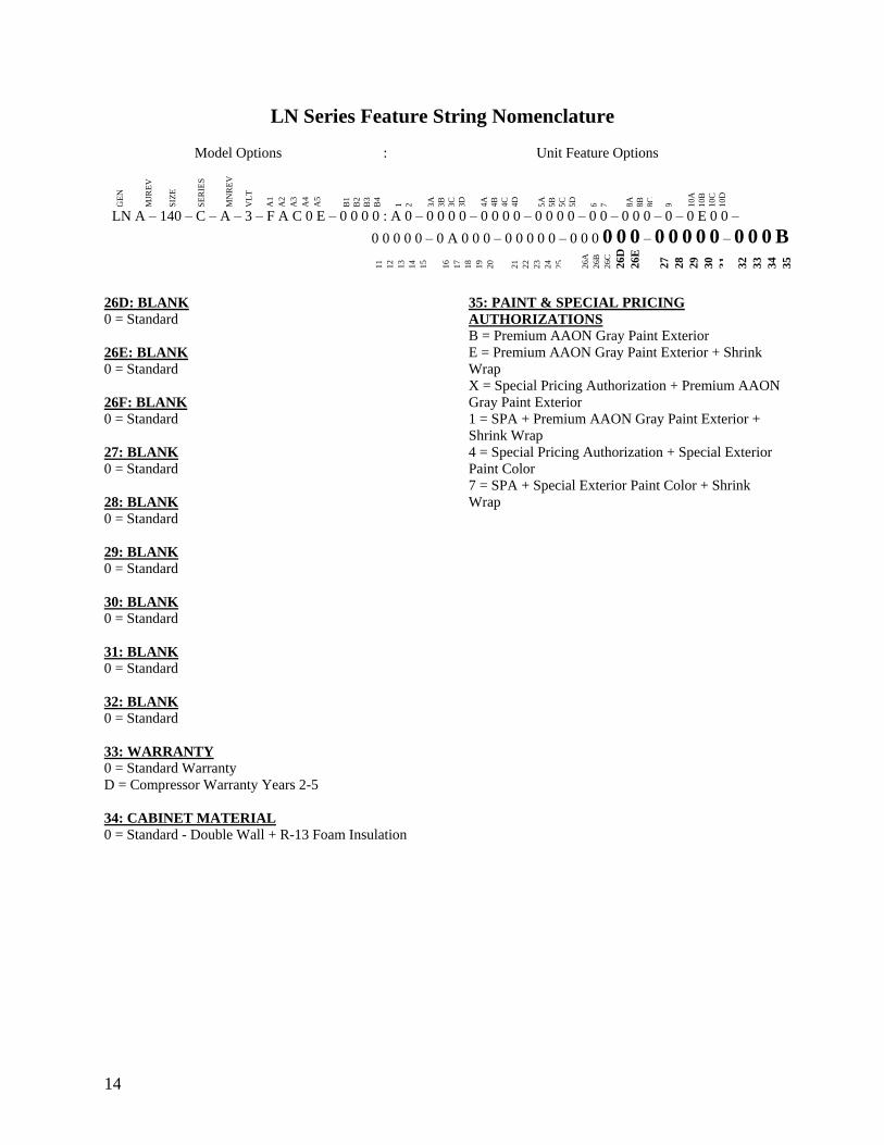
14
LN Series Feature String Nomenclature
Model Options Unit Feature Options
GE
N
MJR
EV
S
IZE
SE
RIE
S
MN
RE
V
VL
T
A1
A2
A3
A4
A5
B1
B2
B3
B4
1
2
3A
3B
3C
3D
4A
4B
4C
4D
5A
5B
5C
5D
6
7
8A
8B
8C
9
10A
10B
10C
10D
LN A ndash 140 ndash C ndash A ndash 3 ndash F A C 0 E ndash 0 0 0 0 A 0 ndash 0 0 0 0 ndash 0 0 0 0 ndash 0 0 0 0 ndash 0 0 ndash 0 0 0 ndash 0 ndash 0 E 0 0 ndash
0 0 0 0 0 ndash 0 A 0 0 0 ndash 0 0 0 0 0 ndash 0 0 0 0 0 0 ndash 0 0 0 0 0 ndash 0 0 0 B
11
12
13
14
15
16
17
18
19
20
21
22
23
24
25
26A
26B
26C
26
D
26
E
26
F
27
28
29
30
31
3
2
33
34
35
26D BLANK
0 = Standard
26E BLANK
0 = Standard
26F BLANK
0 = Standard
27 BLANK
0 = Standard
28 BLANK
0 = Standard
29 BLANK
0 = Standard
30 BLANK
0 = Standard
31 BLANK
0 = Standard
32 BLANK
0 = Standard
33 WARRANTY
0 = Standard Warranty
D = Compressor Warranty Years 2-5
34 CABINET MATERIAL
0 = Standard - Double Wall + R-13 Foam Insulation
35 PAINT amp SPECIAL PRICING
AUTHORIZATIONS
B = Premium AAON Gray Paint Exterior
E = Premium AAON Gray Paint Exterior + Shrink
Wrap
X = Special Pricing Authorization + Premium AAON
Gray Paint Exterior
1 = SPA + Premium AAON Gray Paint Exterior +
Shrink Wrap
4 = Special Pricing Authorization + Special Exterior
Paint Color
7 = SPA + Special Exterior Paint Color + Shrink
Wrap
15
General Information
AAON LN Series chillers are complete self-
contained liquid chilling units They are
assembled wired charged and run-tested
Models are available for air-cooled
applications Chiller primary pumping
packages are available as optional features
Codes and Ordinances
LN Series units have been tested and
certified by ETL in accordance with UL
Safety Standard 1995CSA C222 No 236
System should be sized in accordance with
the American Society of Heating
Refrigeration and Air Conditioning
Engineers Handbook
Installation of LN Series units must conform
to the ICC standards of the International
Mechanical Code the International Building
Code and local building plumbing and
waste water codes All appliances must be
electrically grounded in accordance with
local codes or in the absence of local codes
the current National Electric Code
ANSINFPA 70 or the current Canadian
Electrical Code CSA C221
Receiving Unit
When received the unit should be checked
for damage that might have occurred in
transit If damage is found it should be noted
on the carrierrsquos Freight Bill A request for
inspection by carrierrsquos agent should be made
in writing at once Nameplate should be
checked to ensure the correct model sizes and
voltages have been received to match the job
requirements
If repairs must be made to damaged goods
then the factory should be notified before any
repair action is taken in order to protect the
warranty Certain equipment alteration
repair and manipulation of equipment
without the manufacturerrsquos consent may void
the product warranty Contact AAON
Technical Support for assistance with
Improper installation adjustment alteration service or maintenance can cause property damage personal injury or loss of life Startup and service must be performed by a Factory Trained Service Technician
WARNING
The Clean Air Act of 1990 bans the intentional venting of refrigerant as of July 1 1992 Approved methods of recovery recycling or reclaiming must be followed
CAUTION
Coils and sheet metal surfaces present sharp edges and care must be taken when working with equipment
Failure to observe the following instructions will result in premature failure of your system and possible voiding of the warranty
WARNING
WARNING
16
handling damaged goods repairs and freight
claims (918) 382-6450
Storage
If installation will not occur immediately
following delivery store equipment in a dry
protected area away from construction traffic
and in the proper orientation as marked on the
packaging with all internal packaging in
place Secure all loose-shipped items
Chiller
Failure to observe the following instructions
will result in premature failure of your
system and possible voiding of the warranty
Never turn off the main power supply to the
unit except for complete shutdown When
power is cut off from the unit any
compressors using crankcase heaters cannot
prevent refrigerant migration This means the
compressor will cool down and liquid
refrigerant may accumulate in the
compressor The compressor is designed to
pump refrigerant gas and damage may occur
when power is restored if liquid enters the
compressor
Before unit operation the main power switch
must be turned on for at least 24 hours for
units with compressor crankcase heaters
This will give the crankcase heater time to
clear any liquid accumulation out of the
compressor before it is required to run
Rotation must be checked on all MOTORS AND COMPRESSORS of three phase units All motors to include and not be limited to pump motors and condenser fan motors should all be checked by a qualified service technician at startup and any wiring alteration should only be made at the unit power connection
CAUTION
Scroll compressors are directional and will be damaged by operation in the wrong direction Low pressure switches on compressors have been disconnected after factory testing Rotation should be checked by a qualified service technician at startup using suction and discharge pressure gauges and any wiring alteration should only be made at the unit power connection
CAUTION
CRANKCASE HEATER OPERATION
Units may be equipped with compressor crankcase heaters which should be energized at least 24 hours prior to cooling operation to clear any liquid refrigerant from the compressors
CAUTION
COMPRESSOR CYCLING
3 MINUTE MINIMUM OFF TIME To prevent motor overheating compressors must cycle off for a minimum of 3 minutes
3 MINUTE MINIMUM ON TIME To maintain the proper oil level compressors must cycle on for a minimum of 3 minutes The cycle rate must not exceed 6 starts per hour
WARNING
17
Never cut off the main power supply to the
unit except for complete shutdown Always
control the system from the building
management system or control panel never
at the main power supply (except for
emergency or for complete shutdown of the
system)
Scroll compressors must be on a minimum of
3 minutes and off for a minimum of 3
minutes The cycle rate must be no more than
6 starts per hour
The chiller is furnished with a pressure
differential switch that is factory installed
between the chilled water supply and return
connections This sensor must not be
bypassed since it provides a signal to the unit
controller that water flow is present in the
heat exchanger and the unit can operate
without the danger of freezing the liquid
Compressor life will be seriously shortened
by reduced lubrication and the pumping of
excessive amounts of liquid oil and liquid
refrigerant
Wiring Diagrams
A complete set of unit specific wiring
diagrams in both ladder and point-to-point
form are laminated in plastic and located
inside the control compartment door
General Maintenance
When the initial startup is made and on a
periodic schedule during operation it is
necessary to perform routine service checks
on the performance of the chiller This
includes reading and recording suction
pressures and checking for normal sub-
cooling and superheat See the air-cooled
condenser sections in this manual for specific
details
Chiller Primary Pumping
Primary pumping uses a single pump to move
water (or glycol) through the chiller barrel
and back to the building This pumping
package provides a constant or variable flow
of water to the system The pump is activated
whenever the chiller is given a run signal
Water enters the unit through the return water
piping and then travels through an air
separator to remove any air that is entrapped
in the water Following this the water flows
through a suction guide with strainer The
end of the suction guide is removable for
strainer access The strainer assembly is
composed of two parts the operational
strainer and the startup strainer (located
inside the operational strainer) which is to be
removed 24 hours after startup
The pump is installed after the suction guide
and before a combination valve (Flo-Trex)
This combination valve acts as isolation
valve check valve and flow balancing valve
The shell and tube or brazed plate evaporator
is placed after the combination valve in the
water circuit with a flow switch installed
across its inlet and outlet This flow switch
closes when the velocity is above 07 feet per
second The closing flow switch signals the
control system to indicate flow through the
heat exchanger and allow cooling to activate
as required to maintain the setpoint The
water exiting the chiller evaporator leaves the
unit through the water out connection
18
Automatic Air Vent
There is an automatic air vent installed at the
high point of the system inside the pumping
package compartment The air vent valve
must be in the proper position for operation
Ensure that the small vent cap is loosened two
turns from the closed position allowing air to
be vented from the system It is advisable to
leave the cap on to prevent impurities from
entering the valve See appendix for
additional information
Dual Pumps
When redundant pumping is required factory
installed dual pumps can be ordered A dual
pump is a pump with two independent motors
and pumps in a single casing This dual pump
has a swing split-flapper valve in the
discharge port to prevent liquid recirculation
when only one pump is operating Isolation
valves in the casing allow one pump to be
isolated and removed for service while the
other pump is still operating
The controls package will activate the pump
when the unit is given a run command If the
controls do not recognize flow in 60 seconds
the second pump will be activated and an
alarm signal will be generated If the second
pump does not activate the cooling will be
locked out See appendix for additional
information
Pressure Gauges and Thermometers
Pressure gauges and thermometers are
available as a factory installed option
Thermometers are installed on the inlet and
outlet of the unit One pressure gauge is
installed at each pump This pressure gauge
is connected in three places to the water
piping before the suction guidestrainer after
the suction guide and before the pump and
after the pump There is also a needle valve
at each of these points to isolate the pressure
To measure the pressure at any given point
open the needle valve at that point and close
the other two needle valves One gauge is
used so that the calibration of the pressure
gauge is irrelevant in the calculation of the
differential pressure
Pipe Insulation
The water piping and components on units
with pumping packages are not insulated at
the factory Insulation should be installed on
the water piping after the system has been
checked for leaks
19
Installation
Chiller Placement
The AAON LN Series is designed for
outdoor applications and mounting at ground
level or on a rooftop It must be placed on a
level and solid foundation that has been
prepared to support its weight
The placement relative to the building air
intakes and other structures must be carefully
selected Be sure to observe the dimensions
that are on the rating plate of the chiller for
operational and service clearances
Table 1 - Service Clearances
Location Unit Size
45-140 tons
Front -
(Controls Side) 72rdquo
Back 72rdquo
Ends 96rdquo
Top Unobstructed
Condenser coils and fans must be free of any
obstructions in order to start and operate
properly with a correct amount of airflow
For proper unit operation the immediate area
around condenser must remain free of debris
that may be drawn in and obstruct airflow in
the condensing section
Consideration must be given to obstruction
caused by snow accumulation when placing
the unit
Curb and Steel Mount Installation
Make openings in the roof decking large
enough to allow for water piping electrical
penetrations and workspace only Do not
make openings larger than necessary Set the
curb to coincide with the openings Make
sure curb is level
If the LN is installed on a curb use a curb cap
for the open area under the condenser section
Unit specific curb drawing is included with
job submittal See SMACNA Architectural
Sheet Metal Manual for curb installation
details
Units require rail support along all four sides
of the unit base
When installed at ground level a one-piece
concrete slab should be used with footings
that extend below the frost line Care must
also be taken to protect the coil and fins from
damage due to vandalism or other causes
If unit is elevated a field supplied catwalk is
recommended to allow access to unit service
doors
This unit ships with a curb gasket that is 1frac14rdquo
wide and 1frac12rdquo tall It is recommended that this
or another similar gasket be used between the
curb and the unit to reduce vibration from the
unit to the building
All roofing work should be performed by competent roofing contractors to avoid any possible leakage
CAUTION
Figure 1 - LN Base
20
Figure 2 - Curb Mounting with Dimensions
Figure 3 - Steel Mounting Rail with
Dimensions
Table 2 - Mounting Dimensions
Tons A B C D
45-140 142rdquo 138rdquo 134rdquo 139rdquo
Figure 2
Figure 3
Lifting and Handling
If cables or chains are used to hoist the unit
they must be the same length and care should
be taken to prevent damage to the cabinet
See Figure 5 and Figure 6 for additional
information
Before lifting unit be sure that all shipping
material has been removed from unit Secure
hooks and cables at all lifting points lugs
provided on the unit
Hoist unit to a point directly above the curb
or mounting rail Be sure that the gasket
material has been applied to the curb or
mounting rail
Carefully lower and align unit with utility and
duct openings Lower the unit until the unit
skirt fits around the curb Make sure the unit
is properly seated on the curb and is level
Figure 4 - Lifting Points
21
Figure 5 - Lifting Detail of a 45-60 ton Unit
Figure 6 - Lifting Detail of a 75-140 ton Unit
Lifting slot locations are unit specific
Unit must be rigged at all marked lifting points
22
Water Connection
Connect the supply and return water lines
The connection size is listed on the unit rating
sheet along with the designed volumetric
flow rate The maximum operating pressure
for AAON LN Series units is 125 psi
Mounting Isolation
For roof mounted applications or anytime
vibration transmission is a factor vibration
isolators may be used
Access Doors
Lockable access door is provided to the
compressor and control compartment A
separate access door is also provided to the
pumping package compartment
A light switch with service lights is provided
on the wall of the compressor and control
compartment
End Flashing Installation
On all LN Series units the cabinet width will
overhang the shipping trailer on each side
In order to secure and protect the unit during
transit the sheet metal end flashings have
been removed from the unit The slot created
at the base of each end of the unit allows the
unit to set firmly on the trailer deck
Sheet metal flashings are shipped loose with
the unit and once the unit is set into place the
flashings must be installed on each end of the
unit to complete the finished seal at the base
The flashings are unit specific and designed
to cover the slot at each end of the unit to
prevent water run-off into the curb
Failure to attach and seal the end of unit with
the flashings may result in water leakage into
the curb
Figure 7 - Factory Supplied End Flashings
PVC (Polyvinyl Chloride) and CPVC (Chlorinated Polyvinyl Chloride) are vulnerable to attack by certain chemicals Polyolester (POE) oils used with R-410A and other refrigerants even in trace amounts in a PVC or CPVC piping system will result in stress cracking of the piping and fittings and complete piping system failure
CAUTION
The chiller must be operated only with liquid flowing through the evaporators
WARNING
Installing Contractor is responsible for proper sealing of the water piping entries into the unit Failure to seal the entries may result in damage to the unit and property
CAUTION
23
Low Ambient Operation
If the chiller is ordered for a Low Ambient
application the liquid system must use a
glycol solution and the piping must be
insulated to be prepared for freezing
conditions Care must be taken in the source
of electrical power for the heating tape and
thermostat
Electrical
The single point electrical power connections
are made in the electrical control
compartment
The microprocessor control furnished with
the unit is supplied with its own power supply
factory wired to the main power of the
outdoor mechanical room
Verify the unit nameplate voltage agrees with
the power supply Connect power and control
field wiring as shown on the unit specific
wiring diagram provided with the unit
Size supply conductors based on the unit
MCA rating Supply conductors must be
rated a minimum of 167degF (75degC)
Route power and control wiring separately
through the utility entry Do not run power
and signal wires in the same conduit
Protect the branch circuit in accordance with
code requirements The unit must be
electrically grounded in accordance with
local codes or in the absence of local codes
the current National Electric Code
ANSINFPA 70 or the current Canadian
Electrical Code CSA C221
Power wiring is to the unit terminal block or
main disconnect All wiring beyond this point
has been done by the manufacturer and
cannot be modified without effecting the
units agencysafety certification
Figure 8 - Front View of Utility Entry and
Power Switch from Control Compartment
Electric shock hazard Before attempting to perform any installation service or maintenance shut off all electrical power to the unit at the disconnect switches Unit may have multiple power supplies Failure to disconnect power could result in dangerous operation serious injury death or property damage
WARNING
In order to prevent water leakage into the roof curb the factory provided sheet metal flashings MUST BE attached to the unit base to cover the shipping slots at both ends of the unit
CAUTION
24
Startup technician must check for proper
motor rotation and check fan motor amperage
listed on the motor nameplate is not
exceeded Motor overload protection may be
a function of the variable frequency drive and
must not be bypassed
Note All units are factory wired for
208230V 460V or 575V If unit is to be
connected to a 208V supply the transformer
must be rewired to 208V service For 208V
service interchange the yellow and red
conductor on the low voltage control
transformer
Red-Black for 208V
Yellow-Black for 230V
Wire control signals to the unitrsquos low voltage
terminal block located in the controls
compartment All wiring beyond this point
has been completed by the manufacturer and
cannot be modified without effecting the
unitrsquos agencysafety certification
If any factory installed wiring must be
replaced use a minimum 221degF (105degC) type
AWM insulated conductors
Supply voltage must be within the minmax
range shown on the unit nameplate Available
short circuit current should not exceed the
short circuit current rating (SCCR) shown on
the unit nameplate
Three phase voltage imbalance will cause
motor overheating and premature failure
The maximum allowable imbalance is 5
Voltage imbalance is defined as 100 times the
maximum deviation from the average voltage
divided by the average voltage
Example
(218V+237V+235V)3 = 230V then
100(230V-218V)230V = 52 which
exceeds the allowable imbalance
Check voltage imbalance at the unit
disconnect switch and at the compressor
terminal Contact your local power company
for line voltage corrections
Three phase voltage imbalance will cause motor overheating and premature failure
CAUTION
Scroll compressors are directional and will be damaged by operation in the wrong direction Low pressure switches on compressors have been disconnected after factory testing Rotation should be checked by a qualified service technician at startup using suction and discharge pressure gauges and any wiring alteration should only be made at the unit power connection
Installing Contractor is responsible for proper sealing of the electrical and gas entries into the unit Failure to seal the entries may result in damage to the unit and property
CAUTION CAUTION
25
Variable Speed Compressors
Variable speed compressors should not be
operated outside the factory determined
frequency range The factory determined
compressor VFD frequency range is given
below in Table 3
Table 3- Tandem Circuited Variable Speed
Compressor VFD Frequency Range
Model (LN-) Compressor VFD
Range (Hz)
208V 230V 460V and 575V Units
045 055 060 45-65Hz
075 45-70Hz
095 105 120 35-60 Hz
140 35-65 Hz
No variable speed compressor shall operate below 35 Hz Operating variable speed compressors outside the frequency range specified in this manual voids all warranties and may result in compressor failure
CAUTION
Rotation must be checked on all MOTORS AND COMPRESSORS of three phase units Condenser fan motors should all be checked by a qualified service technician at startup and any wiring alteration should only be made at the unit power connection Variable frequency drives are programmed to automatically rotate the fan in the correct rotation Do not rely on fans with variable frequency drives for compressor rotation
CAUTION
26
Startup (See back of the manual for startup form)
Before the startup of the chiller be sure that
the following items have been checked
1 Verify that electrical power is available to
the unit
2 Verify that any remote stopstart device
connected to the chiller controller is
requesting the chiller to start
3 Verify that liquid flow is present through
the chiller from the building
4 There should be a building load of at least
25 of the chiller capacity in order to
properly check operation
5 With the main power switch off review
the MCS Controller Manual provided
with the chiller Understand the keypad
functions how to set the leaving water
temperature setpoint and how to initiate
the Run State
Use the general check list at the top of the
startup form to make a last check that all the
components are in place water flow is
present and the power supply is energized
Using the controller keypad individually set
the outputs in ldquoManual Onrdquo to confirm relay
closure and compressor operation
Cycle through all the compressors to confirm
that all are operating within tolerance
While performing the check use the startup
form to record observations of compressor
amps and refrigerant pressures
When all is running properly place the
controller in the Run mode and observe the
system until it reaches a steady state of
operation
Note For more information on programming
the controller refer to the MCS Controller
manual provided with the chiller
Electric shock hazard Shut off all electrical power to the unit to avoid shock hazard or injury from rotating parts
WARNING
Improper installation adjustment alteration service or maintenance can cause property damage personal injury or loss of life Startup and service must be performed by a Factory Trained Service Technician
WARNING
Rotation must be checked on all MOTORS AND COMPRESSORS of three phase units All motors to include and not be limited to pump motors and condenser fan motors should all be checked by a qualified service technician at startup and any wiring alteration should only be made at the unit power connection
CAUTION
Before completing installation a complete operating cycle should be observed to verify that all components are functioning properly
CAUTION
27
Axial Flow Condenser Fans
Multi-Wing Z Series Aluminum Fan Blade
Pitch Angle Setting Instructions
1 Maintain the balance of fan
Mark the hub castings across a joint so the
fan hub can be reassembled in the same
orientation
Mark the location of any balancing weight
Balancing weight will be on the outer bolt
circle in the form of washers andor longer
bolts or an additional balancing nut
Number the blades and blade sockets so that
they are replaced into their original position
Figure 9 - Fan with the HUB on the top and
RET on the bottom
2 Determine the direction of rotation
Right R is clockwise when facing the
discharge side of the fan and Left L is
counterclockwise when facing the discharge
side of the fan
3 Determine the bushing mount location
The bushing mount is the center section of the
hub through which the fan is mounted to the
shaft and typically contains either setscrews
or a center-tapered hole where the bushing
inserts
Location A is with the bushing mount on air
inlet side of the fan
Location B is with the bushing mount on air
discharge side of the fan
Figure 10 - Bushing Mount Location
4 Determine the pin location groove
Disassemble fan on a flat surface and note in
which groove the pin is located
Figure 11 - RET with Pin in Groove 4
Bushing
Mount
A B Bushing
Mount
Bushing Bushing
1 2 3 4
28
5 Determine whether the pin is in the HUB
or RET
Figure 12 - Fan HUB and RET Castings
6 Determine the current blade pitch and the pin location for the new blades
Table 4 - ReturnExhaust Fan Pin Location
Type Bushing
Mount
Blade Pitch Angle
20deg 25deg 28deg 30deg 33deg 35deg 38deg 40deg 45deg 50deg
5Z A - RET - RET RET RET HUB HUB HUB HUB
B - HUB - HUB HUB HUB RET RET RET RET
Table 5 - ReturnExhaust Fan Pin Location
Type Rot Blade Pitch Angle
20deg 25deg 28deg 30deg 33deg 35deg 38deg 40deg 45deg 50deg
5Z R - 4 - 3 2 1 4 3 2 1
L - 1 - 2 3 4 1 2 3 4
7 Replace fan blades in the new pin
location and reassemble the fan
Replace the blades with the pin in the 1 2 3
or 4 groove position of either the HUB or
RET Assemble the fan making sure to place
the blades in their previous blade sockets to
match up the previous orientation of HUB
and RET and to replace any balancing
weights in their previous locations Tighten
bolts in a cross pattern to 5-6 ft-lbs of torque
29
Multi-Wing W Series Black Glass
Reinforced Polypropylene Fan Blade Pitch
Angle Setting Instructions
Contact the AAON parts department to
acquire the new pitch pins for the fan blades
Note original position of retaining plates
center boss and all hardware including
additional hardware used for balancing
1 Remove all the bolts and nuts
2 Determine blade rotation ndash on the concave
side of the blade is a blade marking showing
6WR 6WL 7WL 7WR or 9WR The ldquoLrdquo
and ldquoRrdquo denote the rotation of the blade
3 Replace the pitch insert in the blade root
with an insert of the desired pitch
Figure 13 - Pitch Insert
4 Replace blades to their original location
5 Replace all nuts bolts and washers on the
fan hub
6 Replace retaining plates and center boss to
original location
7 Tighten nuts and bolts to 14 ft-lbs of
torque
Fan Assembly Bushings
The fan assembly bushings should be
tightened to the specifications listed in the
following table
Table 6 - Fan Assembly Bushing Torque
Specifications
Bushing Tightening Torque
(in-lbs)
H X 1125 95
H X 1375 95
SH X 1125 108
SH X 1375 108
SD X 1125 108
SD X 1375 108
SD X 1625 108
SD X 1875 108
SK X 2125 180
30
Maintenance
General
Qualified technicians must perform routine
service checks and maintenance This
includes reading and recording the
condensing and suction pressures and
checking for normal sub-cooling and
superheat
Air-cooled chillers require maintenance
schedulesprocedures Unit specific
instructions are included in this manual
Compressors
The scroll compressors are fully hermetic and
require no maintenance except keeping the
shell clean
Refrigerant Suction Line Filter
Each refrigerant circuit contains a
replaceable core suction line filter One
month after start-up remove the filter
element
The replaceable core suction filters are
provided with pressure taps and shutoff
valves for isolation when removing the filter
For safety purposes a service manifold must
be attached prior to filter maintenance
Suction Filter Removal Instructions
1 Shut down operation of the unit
2 Close both shut-off valves to isolate
the suction filter
3 Reclaim the refrigerant from the
suction filter section
4 Remove the bolts from the suction
filter end plate
5 Remove the pleated filter assembly
Prior to filter core service a service manifold MUST BE attached to in and out pressure connections to assure no pressure exists during filter maintenance Non-compliance could result in injury or violation of EPA regulations
Service gauges MUST BE connected before operating the isolation valves for the replaceable core filter
WARNING
WARNING
31
6 Replace the suction filter end plate
and bolts
7 Evacuate the suction filter assembly
to 500 microns
8 Open both shut-off valves
Adjusting Refrigerant Charge
All AAON chillers are shipped with a full
factory charge Periodically adjusting the
charge of a system may be required
Adjusting the charge of a system in the field
must be based on determination of liquid sub-
cooling and evaporator superheat On a
system with an expansion valve liquid sub-
cooling is more representative of the charge
than evaporator superheat but both
measurements must be taken
Before Charging
Refer to the unit nameplate as a reference
when determining the proper refrigerant
charge
Unit being charged must be at or near full
load conditions before adjusting the charge
Units equipped with hot gas bypass must
have the hot gas bypass valve closed to get
the proper charge
After adding or removing charge the system
must be allowed to stabilize typically 10-15
minutes before making any other
adjustments
The type of unit and options determine the
ranges for liquid sub-cooling and evaporator
superheat Refer to Table 7 when determining
the proper sub-cooling
For units equipped with low ambient (0degF)
option see the special charging instructions at
the end of this section
Checking Liquid Sub-cooling
Measure the temperature of the liquid line as
it leaves the condenser coil
Read the gauge pressure at the liquid line
close to the point where the temperature was
taken You must use liquid line pressure as it
will vary from discharge pressure due to
condenser coil pressure drop
Convert the pressure obtained to a saturated
temperature using the appropriate refrigerant
temperature-pressure chart
Subtract the measured liquid line temperature
from the saturated temperature to determine
the liquid sub-cooling
Compare calculated sub-cooling to the table
below for the appropriate unit type and
options
The Clean Air Act of 1990 bans the intentional venting of refrigerant (CFCrsquos and HCFCrsquos) as of July 1 1992 Approved methods of recovery recycling or reclaiming must be followed Fines andor incarceration may be levied for non-compliance
CAUTION
Polyolester (POE) and Polyvinylether (PVE) oils are two types of lubricants used in hydrofluorocarbon (HFC) refrigeration systems Refer to the compressor label for the proper compressor lubricant type
CAUTION
32
Checking Evaporator Superheat
Measure the temperature of the suction line
close to the compressor
Read gauge pressure at the suction line close
to the compressor
Convert the pressure obtained to a saturated
temperature using the appropriate refrigerant
temperature-pressure chart
Subtract the saturated temperature from the
measured suction line temperature to
determine the evaporator superheat
For refrigeration systems with tandem scroll
compressors it is critical that the suction
superheat setpoint on the expansion valve is
set with one compressor running The suction
superheat should be 10-13degF with one
compressor running The suction superheat
will increase with both compressors in a
tandem running Inadequate suction
superheat can allow liquid refrigerant to
return to the compressors which will wash the
oil out of the compressor Lack of oil
lubrication will destroy a compressor Liquid
sub-cooling should be measured with both
compressors in a refrigeration system
running
Compare calculated superheat to Table 7 for
the appropriate unit type and options
Table 7 - Acceptable Refrigeration Circuit
Values
Air-Cooled Chiller with Scroll
Compressors
Sub-Cooling2 12-18degF
Superheat1 10-15degF 1 One compressor running in tandem 2 Two compressors running in tandem
Adjusting Sub-cooling and Superheat
Temperatures
The system is overcharged if the sub-cooling
temperature is too high and the evaporator is
fully loaded (low loads on the evaporator
result in increased sub-cooling) and the
evaporator superheat is within the
temperature range as shown in Table 7 (high
superheat results in increased sub-cooling)
Correct an overcharged system by reducing
the amount of refrigerant in the system to
lower the sub-cooling
The system is undercharged if the superheat
is too high and the sub-cooling is too low
Correct an undercharged system by adding
refrigerant to the system to reduce superheat
and raise sub-cooling
If the sub-cooling is correct and the superheat
is too high the expansion valve may need
adjustment to correct the superheat
Expansion valves must be adjusted to approximately 10-15degF of suction superheat Failure to have sufficient superheat will damage the compressor and void the warranty
CAUTION
DO NOT OVERCHARGE Refrigerant overcharging leads to excess refrigerant in the condenser coils resulting in elevated compressor discharge pressure
CAUTION
33
Table 8 - R-410A Refrigerant Temperature-Pressure Chart
F psig F psig F psig F psig F psig
20 783 50 1422 80 2349 110 3641 140 5401
21 800 51 1448 81 2386 111 3691 141 5470
22 818 52 1474 82 2423 112 3742 142 5539
23 836 53 1501 83 2460 113 3794 143 5609
24 854 54 1528 84 2498 114 3846 144 5679
25 872 55 1555 85 2537 115 3899 145 5751
26 891 56 1582 86 2575 116 3952 146 5823
27 910 57 1610 87 2614 117 4005 147 5896
28 929 58 1638 88 2654 118 4059 148 5969
29 949 59 1667 89 2694 119 4114 149 6044
30 968 60 1696 90 2735 120 4169 150 6119
31 988 61 1725 91 2776 121 4225
32 1009 62 1754 92 2817 122 4282
33 1029 63 1784 93 2859 123 4339
34 1050 64 1815 94 2901 124 4396
35 1071 65 1845 95 2944 125 4454
36 1092 66 1876 96 2987 126 4513
37 1114 67 1907 97 3030 127 4573
38 1136 68 1939 98 3075 128 4632
39 1158 69 1971 99 3119 129 4693
40 1181 70 2004 100 3164 130 4754
41 1203 71 2036 101 3210 131 4816
42 1227 72 2070 102 3256 132 4878
43 1250 73 2103 103 3302 133 4941
44 1274 74 2137 104 3349 134 5005
45 1298 75 2171 105 3396 135 5069
46 1322 76 2206 106 3444 136 5134
47 1347 77 2241 107 3493 137 5200
48 1372 78 2277 108 3542 138 5266
49 1397 79 2313 109 3591 139 5333
34
Lubrication
All original motors and bearings are
furnished with an original factory charge of
lubrication Certain applications require
bearings be re-lubricated periodically The
schedule will vary depending on operating
duty temperature variations or severe
atmospheric conditions
Bearings should be re-lubricated at normal
operating temperatures but not when
running
Rotate the fan shaft by hand and add only
enough grease to purge the seals DO NOT
OVERLUBRICATE
Air-Cooled Condenser
The air-cooled condenser section rejects heat
by passing outdoor air over the fin tube coils
for cooling of the hot refrigerant gas from the
compressors The heated air will discharge
from the top of the section through the axial
flow fans
The condenser coils should be inspected
yearly to ensure unrestricted airflow If the
installation has a large amount of airborne
dust or other material the condenser coils
should be cleaned according to the
microchannel coil cleaning section
Brazed Plate Heat Exchanger Cleaning
Because of a normally high degree of
turbulence in brazed plate heat exchangers
for many applications the heat exchanger
channels are self-cleaning For applications
that are not self-cleaning (ie hard water at
high temperatures etc) or applications where
additional cleaning is desired it is possible to
clean the brazed plate heat exchanger by
circulating a cleaning liquid
Use a tank with weak acid 5 phosphoric
acid (H3PO4) or if the exchanger is
frequently cleaned 5 oxalic acid (H2C2O4)
Pump the cleaning liquid through the
exchanger For optimum cleaning the
cleaning solution flow rate should be a
minimum of 15 times the normal flow rate
preferably in a back-flush mode After
cleaning the heat exchanger must be rinsed
with clean water A solution of 1-2 sodium
hydroxide (NaOH) or sodium bicarbonate
(NaHCO) before the last rinse ensures that all
acid is neutralized
E-Coated Coil Cleaning
Documented quarterly cleaning of e-coated
coils is required to maintain coating warranty
coverage
Surface loaded fibers or dirt should be
removed prior to water rinse to prevent
restriction of airflow If unable to back wash
the side of the coil opposite of the coils
entering air side then surface loaded fibers or
dirt should be removed with a vacuum
cleaner If a vacuum cleaner is not available
a soft non-metallic bristle brush may be used
In either case the tool should be applied in
the direction of the fins Coil surfaces can be
easily damaged (fin edges bent over) if the
tool is applied across the fins
Use of a water stream such as a garden hose
against a surface loaded coil will drive the
fibers dirt and salts into the coil This will
make cleaning efforts more difficult Surface
loaded fibers must be completely removed
prior to using low velocity clean water rinse
Electric shock hazard Shut off all electrical power to the unit to avoid shock hazard or injury from rotating parts
WARNING
35
Quarterly cleaning is required to maintain
warranty coverage and is essential to
maintain the life of an E-coated coil Coil
cleaning shall be part of the units regularly
scheduled maintenance procedures
Failure to clean an E-coated coil on the
prescribed quarterly cycle will void the
warranty and may result in reduced
efficiency and durability in the environment
A routine two-step quarterly coil cleaning is
required to maintain warranty
Step one is to clean the coil with the below
approved coil cleaner (see approved products
list under the Recommended Coil Cleanersrdquo
section
Step two is to use the approved saltchloride
remover under the Recommended Chloride
Removerrdquo section to dissolve soluble salts
and revitalize the unit It is very important
when cleaning andor rinsing not to exceed
130degF and potable water pressure is less than
100 psig to avoid damaging the unit and coil
fin edges
For routine quarterly cleaning first clean the
coil with the below approved coil
cleaner After cleaning the coils with the
approved cleaning agent use the approved
chloride remover to remove soluble salts and
revitalize the unit
Recommended Coil Cleaner ndash Step 1
GulfCoatTM Coil Cleaner assuming it is
used in accordance with the manufacturers
directions on the container for proper mixing
and cleaning has been approved for use on
E-coated coils to remove mold mildew dust
soot greasy residue lint and other
particulate Never use any cleaners that are
not approved
Recommended Chloride Remover ndash Step 2
CHLORRIDreg Concentrate assuming it
is used in accordance with the manufacturers
directions on the container for proper mixing
has been approved for use on E-coated coils
to remove chloridessalts amp sulfates Never
use any chloride removers that are not
approved
Warranty Protection ndash Step 1
Complete the coil cleaning following these
steps
1 Ensure that the power to the unit is off
and locked out
2 Clean the area around the unit if
needed to ensure leaves grass or
High velocity water from a pressure washer or compressed air should only be used at a very low pressure to prevent fin andor coil damages The force of the water or air jet may bend the fin edges and increase airside pressure drop Reduced unit performance or nuisance unit shutdowns may occur
Harsh chemicals household bleach or acid cleaners should not be used to clean e-coated coils These cleaners can be very difficult to rinse out of the coil and can accelerate corrosion and attack the e-coating If there is dirt below the surface of the coil use the recommended coil cleaners
CAUTION
CAUTION
36
loose debris will not be blown into the
coil
3 Remove panels or tops as required
gaining access to the coil(s) to be
cleaned
4 Using a pump up sprayer fill to the
appropriate level with potable water
and add the correct amount of
approved cleaner as per manufacture
instructions leaving room for the
pump plunger to be reinserted
NOTE Coils should always be cleaned
back flushed opposite of airflow to prevent
impacting the dirt into the coil
5 If the coils have heavy dirt fibers
grass leaves etc on the interior or
exterior face areas a vacuum and
brush should be used to remove those
surface contaminants prior to
applying cleaner The interior floor
drain tray or pan areas should also be
vacuumed
6 Apply the mixed cleaner to coil
surfaces using a pressurized pump up
sprayer maintaining a good rate of
pressure and at a medium size nozzle
spray (not a solid stream and not a
wide fan but somewhere in the
middle) Work in sectionspanels
ensuring that all areas are covered and
kept wetted
7 Apply the cleaner to unit interior air
exiting side coil surfaces first Work
in sectionspanels moving side to side
and from top to bottom
8 Generously soak coils by spraying
cleaner directly on and into the fin
pack section to be cleaned and allow
the cleaning solution to soak for 5 to
10 minutes
9 Using pressurized potable water
(lt100 psi) rinse the coils and
continue to always work in
sectionspanels Start at the top of the
coil and slowly move vertically
downward to the bottom Then
staying in the same vertical area
slowly move back up to the top where
you started Now move over slightly
overlapping the area just completed
and repeat above Continue until all
coil areas on the inside of the unit
have been rinsed
10 Complete steps 5-9 for the exterior air
entering side of the coils
11 Final rinse ndash Now complete a quick
rinse of both sides of the coil
including the headers piping u-
bends and hairpins
12 If the coil has a drain pan or unit floor
that is holding rinse water or cleaner
extra time and attention will need to
be taken in those areas to ensure a
proper rinse has been completed
Warranty Protection ndash Step 2
Complete the coil chloride (salt) removal
following these steps
1 CHLORRIDreg is a concentrate to be
used for both normal inland
applications at a 1001 mix ratio OR
for severe coastal applications 501
mix ratio with potable water (256
ounces of Chlorrid to 1 gal of water)
Using a pump up sprayer fill to the
appropriate level with potable water
and add the correct amount of
CHLORRIDreg salt remover leaving
room for the pump plunger to be
reinserted
2 Apply CHLORRIDreg to all external
coil surfaces using a pressurized
pump up sprayer maintaining a good
rate of pressure and at a medium size
nozzle spray (not a solid stream and
not a wide fan but somewhere in the
middle) Work in sectionspanels
ensuring that all areas are covered and
kept wetted
37
3 Generously soak coils by spraying
CHLORRIDreg directly on and into
the fin pack section Let stand for 5 to
10 minutes keeping the area wetted
Do not allow to dry before rinsing
4 Using pressurized potable water
(lt100 psi) rinse the CHLORRIDreg
and dissolved chloridessalts off of
the coils continuing to always work in
sectionspanels
5 Starting at the top of the coil begin
rinsing the coil from side to side until
you reach the bottom Repeat as many
times as is necessary to ensure all coil
sectionspanels have been completed
and are thoroughly rinsed
6 Reinstall all panels and tops that were
removed
Microchannel Coil Cleaning
Documented routine cleaning of
microchannel coils with factory provided e-
coating is required to maintain coating
warranty coverage See E-Coated Coil
Cleaning section
Air-cooled heat exchangers may include
microchannel coils
Cleaning microchannel coils is necessary in
all locations In some locations it may be
necessary to clean the coils more or less often
than recommended In general a condenser
coil should be cleaned at a minimum of once
a year In locations where there is commonly
debris or a condition that causes dirtgrease
build up it may be necessary to clean the coils
more often Proper procedure should be
followed at every cleaning interval Using
improper cleaning technique or incorrect
chemicals will result in coil damage system
performance fall off and potentially leaks
requiring coil replacement
Documented routine cleaning of
microchannel coils with factory provided e-
coating is required to maintain coating
warranty coverage Use the E-Coated Coil
Cleaning section for details on cleaning e-
coated coils
Field applied coil coatings are not
recommended with microchannel coils
Allowed Chemical Cleaners and Procedures
AAON recommends certain chemicals that
can be used to remove buildup of grime and
debris on the surface of microchannel coils
These chemicals have been tested for
performance and safety and are the only
chemicals that AAON will warrant as correct
for cleaning microchannel coils
There are three procedures that are outlined
below that will clean the coils effectively
without damage to the coils Use of any other
procedure or chemical may void the warranty
to the unit where the coil is installed With
all procedures make sure the unit is off
before starting
The water pressure used to clean should not
exceed 140 psi from no closer than 6 inches
from the coils and with the water aimed
perpendicular to the coils
Electric shock hazard Shut off all electrical power to the unit to avoid shock hazard or injury from rotating parts
WARNING
WARNING
38
1 Simple Green
Simple Green is available from AAON Parts
and Supply (Part T10701) and is
biodegradable with a neutral 65 pH
Recommendation is to use it at a 4 to 1 mix
Use the following procedure
1 Rinse the coil completely with water Use
a hard spray but be careful not to bend or
damage the fins A spray that is too hard
will bend the fins Spray from the fan side
of the coil
2 With a pump sprayer filled with a mix of
4 parts water to one part Simple Green
spray the air inlet face of the coil Be sure
to cover all areas of the face of the coil
3 Allow the coil to soak for 10-15 minutes
4 Rinse the coil with water as in step one
5 Repeat as necessary
2 Vinegar
This is standard white vinegar available in
gallons from most grocery stores It has a pH
of 2-3 so it is slightly acidic Use the
following procedure
1 Rinse the coil completely with water Use
a hard spray but be careful not to bend or
damage the fins A spray that is too hard
will bend the fins Spray from the fan side
of the coil
2 Use a pump sprayer filled with vinegar
(100) Spray from the face of the coil in
the same direction as the airflow Be sure
to cover all areas of the face of the coil
3 Allow the coil to soak for 10-15 minutes
4 Rinse the coil with water as in step one
5 Repeat as necessary
3 Water Flush
This procedure can be used when the only
material to cause the coil to need cleaning is
debris from plant material that has impinged
the coil face
1 Rinse the coil completely with water Use
a hard spray but be careful not to bend or
damage the fins A spray that is too hard
will bend the fins Spray from the fan side
of the coil
2 Spray and rinse the coil from the face
Application Examples
The three procedures can be used to clean
microchannel coils They will fit with the
application depending on the area In some
areas where the springsummer has a large
cottonwood bloom 3 might work fine if the
unit is installed on an office building and no
other environmental factors apply
When a unit is installed where the sprinkler
system has water being sprayed onto the
condenser coil you might have better results
using 2 Vinegar is slightly acidic and may
help with the calcium build up from drying
water This also works well when grease is
part of the inlet air to a condenser coil
Generally the best and broadest based
procedure is 1 The grease cutting effect of
the Simple Green is good for restaurant
applications
Other Coil Cleaners
There are many cleaners on the market for
condenser coils Before using any cleaner
that is not covered in this section you must
get written approval from the AAON
warranty and service department Use of
unapproved chemicals will void the
warranty
Use pressurized clean water with pressure not to exceed 140 psi Nozzle should be 6rdquo and 80deg to 90deg from coil face Failure to do so could result in coil damage
CAUTION
39
AAON testing has determined that unless a
chemical has a neutral pH (6-8) it should not
be used
Beware of any product that claims to be a
foaming cleaner The foam that is generated
is caused by a chemical reaction to the
aluminum fin material on tube and fin coils
and with the fin tube and coating material on
microchannel coils
Microchannel coils are robust in many ways
but like any component they must be treated
correctly This includes cleaning the coils
correctly to give optimal performance over
many years
Service
If the unit will not operate correctly and a
service company is required only a company
with service technicians qualified and
experienced in both refrigerant chillers and
air conditioning are permitted to service the
systems to keep warranties in effect If
assistance is required the service technician
must contact AAON
Replacement Parts
Parts for AAON equipment may be obtained
from your local AAON representative When
ordering parts reference the unit serial
number and part number
AAON Technical Support
2424 S Yukon Ave
Tulsa OK 74107
Ph (918) 382-6450
techsupportAAONcom
wwwAAONcom
Note Before calling technician should have
model and serial number of the unit available
for the service department to help answer
questions regarding the unit
40
Appendix - Water Piping Component Information
Automatic Air Vent Valves
Automatic Air Vent Valves provide
automatic air venting for hot or cold water
distribution systems These vents purge air
that may be in the water system
The vent valve utilizes a float to actuate the
valve plug which is located at the top of the
valve Once the air is displaced and the
system pressure is sustained the valve plug
seals and prevents any water from escaping
from the system
The float vent can also operate as an anti-
vacuum device since it will permit air to enter
the system when it must be drained It can
also be installed to permit the separation and
dispersal of air while fluid is actually
circulating in the system
Overview
Body and cover are brass construction
Air vent with silicone rubber seal
Impurities do not usually affect function
as maximum float line of water is always
lower than the valve seal
Float is high temperature resistant
polyethylene
Suitable for use with glycol systems
Can be disassembled for inspection and
cleaning
Operating Range
Minimum working pressure 145psi
(10 kPa)
Maximum working pressure 150psi
(10 bars)
Temperature Range 33degF ndash 240degF
(5degC ndash 116degC)
Performance
Performance curve details the quantity of air
vented by the ldquoFloat Ventrdquo according to the
pressure in the system
Note In order to get the best results in
venting air from risers use connecting pipes
41
of at least 1frasl2 diameter between the ldquoFloat
Ventrdquo valves and installation
Installation
When the air vent valve is installed as shown
the air will not be vented while the fluid is
circulating in the system but it can vent when
the system is shut off
The figure below shows the installation of the
vent valve for the venting of air while the
fluid is circulating in the system and the
required increase in pipe size in order to
obtain proper separation of air from water
The valve should be mounted only in a
vertical position as its operation is based on
the vertical movement of the float
While the air vent valve is in operation back
off the small vent cap two turns This is the
proper operating setting which will allow air
to be vented from the system It is advisable
to leave the cap on to prevent impurities from
entering the valve
Maintenance
No maintenance is normally necessary
However if the FV-4M1 is disassembled for
inspection or cleaning it is important that
when re-assembling to ensure that the spring
loaded lever properly engages under the float
collar
42
Dimensions ndash Weights
Pumps - Installation and Operating
Instructions
Introduction
This document contains specific information
regarding the safe installation operating and
maintenance of Vertical In-Line pumps and
should be read and understood by installing
operating and maintenance personnel The
equipment supplied has been designed and
constructed to be safe and without risk to
health and safety when properly installed
operated and maintained The instructions
following must be strictly adhered to If
clarification is needed on any point please
contact Armstrong quoting the equipment
serial number
Where under normal operating conditions the
limit of 68degC155degF (Restricted Zone) for
normal touch or 80degC176degF (Unrestricted
Zone) for unintentional touch may be
experienced steps should be taken to
minimize contact or warn operatorsusers that
normal operating conditions will be
exceeded In certain cases where the
temperature of the pumped liquid exceeds the
above stated temperature levels pump casing
temperatures may exceed 100degC212degF and
not withstanding pump insulation techniques
appropriate measures must be taken to
minimize risk for operating personnel
Storage
Pumps removed from service and stored
must be properly prepared to prevent
excessive rusting Pump port protection
plates must not be removed until the pump is
ready to connect to the piping Rotate the
shaft periodically (At least monthly) to keep
No Installation of this equipment should take place unless this document has been read and understood
CAUTION
43
rotating element free and bearings fully
functional
For long term storage the pump must be
placed in a vertical position in a dry
environment Internal rusting can be
prevented by removing the plugs at the top
and bottom of the casing and drain or air blow
out all water to prevent rust buildup or the
possibility of freezing Be sure to reinstall the
plugs when the unit is made operational
Rust-proofing or packing the casing with
moisture absorbing material and covering the
flanges is acceptable When returning to
service be sure to remove the drying agent
from the pump
Handling Large VIL Units
One effective way of lifting a large pumping
unit is to place lifting hooks through the
motor lifting rings or straps around the upper
part of the motor The pump and motor unit
will free-stand on the casing ribs Remove the
coupling guard and place (2) lifting straps
through the pumpmotor pedestal one on
each side of the motor shaft and secure to the
lifting device
With the straps in place using a spacer bar if
necessary to protect the motor fan cover the
whole assembly can now be lifted securely
Note Handling transportation and
installation of this equipment should only be
undertaken by trained personnel with proper
use of lifting equipment
Remove coupling guard and place lifting
straps on each side of coupling use spacer
bar if necessary to protect motor fan cover
Vertical Inline Pump Lifting Strap
Positioning
Note All split-coupled pumps contain a
tapped hole in the motor bracket above the
discharge flange for draining the well Pipe
this drain hole to a floor drain to avoid
overflow of the cavity caused by collecting
chilled water condensate or from seal failure
Pump Piping - General
The discharge valve only is to be used to
throttle pump flow not the suction valve
Care must be taken in the suction line layout
and installation as it is usually the major
source of concern in centrifugal pump
applications
Discharge valve only is to be used to throttle pump flow
Use Caution Piping may carry high temperature fluid
CAUTION
CAUTION
44
Alignment
Alignment is unnecessary on close-coupled
pumps as there is no shaft coupling
Split-coupled units are accurately aligned at
the factory prior to being shipped and do not
need re-aligning when installed
Pump Operation
Starting Pump
Ensure that the pump turns freely by hand or
with some mechanical help such as a strap
and lever on larger pumps Ensure that all
protective guarding is securely fixed in
position
The pump must be fully primed on start up
Fill the pump casing with liquid and rotate the
shaft by hand to remove any air trapped in the
impeller On split coupled units any air
trapped in the casing as the system is filled
must be removed by the manual air vent in
the seal flush line Close-coupled units are
fitted with seal flushvent lines piped to the
pump suction area When these units operate
residual air is drawn out of the pump towards
the suction piping
lsquoBumprsquo or energize the motor momentarily
and check that the rotation corresponds with
the directional arrow on the pump casing To
reverse rotation of a three phase motor
interchange any two power leads
Start the pump with the discharge valve
closed and the suction valve open and then
gradually open the discharge valve when the
motor is at operating speed The discharge
valve may be lsquocrackedrsquo or open slightly at
start up to help eliminate trapped air
When stopping the pump Close the
discharge valve and de-energize the motor
DO NOT run the pump against a closed
discharge valve for an extended period of
time (A few minutes maximum)
Star-Delta motor starters should be fitted
with electronicmechanical interlocks that
have a timed period of no more than 40
milliseconds before switching from star
(Starting) to delta (Run) connection yet allow
the motor to reach full star (Starting) speed
before switching to delta (Run)
Should the pump be noisy or vibrate on start-
up a common reason is overstated system
head Check this by calculating the pump
operating head by deducting the suction
pressure gauge value from the discharge
gauge reading Convert the result into the
units of the pump head as stated on the pump
nameplate and compare the values Should
the actual pump operating head be
significantly less than the nameplate head
value it is typically permissible to throttle the
discharge isolation valve until the actual
operating head is equal to the nameplate
value
Any noise or vibration usually disappears
The system designer or operator should be
made aware of this soon as some adjustment
may be required to the pump impeller
diameter or drive settings if applicable to
make the pump suitable for the system as
installed
Do not run pumps with discharge valve closed or under very low flow conditions
CAUTION
Check rotation arrow prior to operating the unit
CAUTION
45
Check rotation arrow prior to operating the
unit The rotation of all Vertical In-Line units
is ldquoclockwiserdquo when viewed from the drive
end (Looking from on top of behind the
motor)
General Care
Vertical In-Line pumps are built to operate
without periodic maintenance other than
motor lubrication on larger units A
systematic inspection made at regular
intervals will ensure years of trouble-free
operation giving special attention to the
following
Keep unit clean
Keep moisture refuse dust or other loose
particles away from the pump and
ventilating openings of the motor
Avoid operating the unit in overheated
surroundings (Above 100ordmF40ordmC)
Any possibility of the unit starting while
being serviced must be eliminated
If mechanical seal environmental accessories
are installed ensure water is flowing through
the sight flow indicator and that filter
cartridges are replaced as recommended
Pump Lubrication
Lubrication is not required There are no
bearings in the pump that need external
lubrication service
Large Series split-coupled units are installed
with a shaft bushing located beneath the
impeller that is lubricated from the pump
discharge This bearing is field removable for
service on the 20x20x19 size without
disturbing the motor or other major pump
components
Motor
Follow the lubrication procedures
recommended by the motor manufacturer
Many small and medium sized motors are
permanently lubricated and need no added
lubrication Generally if there are grease
fittings evident the motor needs periodic
lubrication and if there are no grease fittings
evident no periodic lubrication is required
Check the lubrication instructions supplied
with the motor for the particular frame size
indicated on the motor nameplate
Mechanical Seal
Mechanical seals require no special attention
The mechanical seal is fitted with a flush line
The seal is flushed from discharge of the
pump casing on split-coupled pumps and is
flushedvented to the suction on close
coupled pumps
The split-coupled pump is flushed from the
pump discharge because the mechanical seal
chamber is isolated from the liquid in the
pump by a throttle bushing Because the seal
chamber is isolated seal environmental
controls such as filters and separators when
installed in the split-coupled flush line are
very effective as only the seal chamber needs
cleansing and will prolong seal life in HVAC
systems
Do not run the pump unless properly filled
with water as the mechanical seals need a
film of liquid between the faces for proper
operation
Electric shock hazard Before attempting to perform any service or maintenance on pumping unit disconnect power source to the driver LOCK IT OFF and tag with the reason
WARNING
46
Mechanical seals may lsquoweeprsquo slightly at
start-up Allow the pump to continue
operating for several hours and the
mechanical seal to lsquoseatrsquo properly prior to
calling for service personnel
System Cleanliness
Before starting the pump the system must be
thoroughly cleaned flushed and drained and
replenished with clean liquid
Welding slag and other foreign materials
ldquoStop Leakrdquo and cleaning compounds and
improper or excessive water treatment are all
detrimental to the pump internals and sealing
arrangement
Proper operation cannot be guaranteed if the
above conditions are not adhered to
Note
Particular care must be taken to check the
following before the pump is put into
operation
1 Pump primed
2 Rotation OK
3 Lubrication OK
4 Pipe work properly supported
5 Voltage supply OK
6 Overload protection OK
7 Is the system clean
8 Is the area around the pump clean
Warranty
Does not cover any damages to the
equipment resulting from failure to observe
the above precautions
Noise Levels
Estimated Pumping Unit Sound Power Level Decibels A-Weighted at 1 m (3 ft) from unit
Double Check Prior to Startup
CAUTION
47
Vibration Levels
Vertical In-Line pumps are designed to meet vibration levels set by Hydraulic Institute Standard
HI Pump Vibration 964 Standard levels are as detailed below
Dual Pump Specific Information
Dual Pump Flapper Valve Operating
Instructions
This unit is fitted with internal valves to allow
isolation of one pump for service and to
automatically prevent recirculation of the
flow when only one pump is running
Procedure for Parallel or Stand-By
Pumping
Discharge and suction valve stems should be
locked in the center position This is
indicated by both locking handles in the
vertical position and the center pin of the
locking arms (4) locked by the handles This
procedure allows the discharge flapper valves
to pivot freely and locks the suction valve
firmly in the center position
Procedure for Isolation of One Side
1 Stop the pump to be serviced
2 Close and lock the suction and discharge
valves as per instructions below
3 Ensure seal flush line interconnection
valve is closed and drain the isolated
casing
4 Service isolated pump as required
Procedure for Starting the Pump after
Servicing
1 Ensure serviced pump is fully re-
assembled including all seal flush lines
and drain plugs
2 Fill the dry casing with system fluid by
opening the seal flush line
interconnecting valve and the air vent
fitting
3 Allow the pressure to equalize in the two
casings if necessary by opening seal
flush line interconnected valve
4 Unlock the discharge valve as per
instructions below
5 Unlock the suction valve as per
instructions below
NOTE Keep hands and tools away from
locked suction valve arm as the differential
pressure may cause the arm to rotate quickly
with force when unlocked
6 Close the seal flush line interconnect
valve and restart pump
Valve Operation - Refer to following 3rdquo 4rdquo
amp 6rdquo valve illustration and the 8rdquo valve
illustration
48
Discharge Valve
This valve performs the dual function of
automatically sealing the discharge of the
inactive pump when one pump is running and
can manually be closed and locked to isolate
one pump for service
Automatic Flapper Operation
In the flapper mode the two halves of the
discharge valve are free to pivot
independently under normal operating
conditions The locking handle (3) should be
secured with the set screw (11) in the vertical
position with the center pin of the locking
arm (4) trapped by the locking handle (3)
Manual Valve Locking
The locking feature of this valve is to ensure
a positive seal (leak proof) of the discharge
port on the pump to be serviced
Note Ensure the pump to be isolated is not
operating before attempting to release the
locking mechanism Failure to do so may
result in injury to the operator andor damage
to the pump
Locking
1 Loosen discharge side set screw (11) to
release the locking handle (3)
2 Rotate the discharge side locking handle
(3) so that the handle points toward the
pump to be serviced and secure in the
horizontal position using set screw (11)
This releases the discharge locking arm
(4)
3 Rotate discharge valve shaft (16) towards
the pump to be isolated The orientation
of the shaft is indicated by the center pin
on the locking arm (4)
4 Raise the locking handle (3) so that the
cam on the base of the handle forces the
pin of the locking arm (4) towards the
pump to be isolated The locking handle
(3) should be raised to between 45
degrees and the vertical position
5 Tighten set screw (11) to lock the locking
handle (3) in position
This handle should not be rotated past the
vertical position
Note Ensure the isolated pump is not
operating before attempting to release the
locking mechanism Failure to do so may
result in injury to the operator andor damage
the pump
Unlocking
1 Open the interconnecting valve on the
seal flush line to pressurize the serviced
pump and vent air through bleeder valve
on series 4302
2 Close these valves once the pressure is
equalized and air removed
3 Loosen set screw (11) and lower locking
handle (3) to the horizontal position
secure with set screw (11)
4 Rotate valve to center position so that the
center pin of the locking arm (4) locates
in the recess on the locking handle (3)
5 Loosen set screw (11) and raise locking
arm (3) to the vertical position locking
the center pin in the locking arm recess
secure with set screw (11)
Suction Valve
Manual Operation
The suction side valve is designed for use as
a manually operated isolation valve This
valve is not designed to automatically pivot
as the discharge flappers do
Locking
1 Loosen suction side set screw (11) to
release the locking handle (3)
Care should be taken when performing procedures 3 and 4 Read instructions carefully
WARNING
49
2 Rotate the suction side locking handle (3)
so that the handle points towards the
pump to be serviced and secure in the
horizontal position using set screw (11)
This releases the suction locking arm (4)
Note The locking handle (3) should only be
rotated towards the pump stopped for service
The suction valve is designed to prevent the
locking handle (1) from rotating towards the
running pump as the suction of the running
pump could cause the valve to slam shut with
sufficient force to injure the operator andor
cause damage to the pump Do not attempt to
circumvent this safety feature
3 Rotate the suction valve towards the
pump to be isolated The orientation of
the shaft is indicated by the center pin on
the locking arm (4)
4 Loosen set screw (11) and raise the
locking handle (3) so that the cam on the
base on the handle forces the pin of the
locking arm (4) towards the pump to be
isolated The locking handle (3) should be
raised to between 45 degrees and the
vertical position
This handle should not be rotated past the
vertical position
5 Tighten set screw (11) to secure the
locking handle (3) in position
Unlocking
1 Open the interconnecting valve on the
seal flush line to pressurize the serviced
pump and vent air through bleeder valve
on series 4302 Close these valves once
the pressure is equalized and air removed
2 Loosen set screw (11) and lower locking
handle (3) to the horizontal position
secure with set screw (11)
NOTE Keep hands and tools away from
suction valve locking arm when freed by
locking handle as differential pressure may
cause arm to rotate quickly with force when
unlocked
3 Rotate valve to center position so that the
center pin of the locking arm (4) is
located in the recess on the locking
handle (3)
4 Loosen set screw (11) and raise locking
arm (3) to the vertical position locking
the center pin in the locking arm recess
secure with set screw
Care should be taken when performing procedures 3 and 4 Read instructions carefully
WARNING
50
51
52
Suction Guides
Introduction
Suction Guides are designed for bolting
directly onto the suction flange of horizontal
or vertical shaft centrifugal pumps
Operating Limits
The suction guide is designed to be a four-
function fitting Each Suction Guide is a 90ordm
elbow a Pipe Strainer and a Flow Stabilizer
It may also be used as a Reducing Elbow
should the suction piping be larger than the
pump inlet
Installation
The Suction Guides may be installed in any
arrangement feasible the arrangement of the
pump flange bolt-holes
Inspection
Suction Guides are thoroughly tested and
inspected before shipment to assure they
meet with your order requirements All units
must be carefully examined upon arrival for
possible damage during transit Any evidence
of mishandling should be reported
immediately to the carrier and noted on the
freight bill
Operation
No special attention need be paid to the
Suction Guide at start-up The fitting is
stationary and will strain the pumped fluid
and stabilize the flow into the pump
automatically
Temporary strainer must be removed
following system clean up
After all debris has been removed from the
system or a maximum of 24 running hours
stop the pump and close the pump isolation
valves Drain the Suction Guide by removing
the drain plug or opening the blowdown
valve if installed
Remove the Suction Guide cover and remove
the strainer assembly from the valve body
A temporary fine-mesh start-up strainer is
tack-welded to the permanent stainless steel
strainer This temporary strainer should now
be removed from the permanent strainer The
fine-mesh strainer is designed to remove
small particulate from new piping systems
and could easily clog with debris if left in
53
place This will be detrimental to the
operation of the pump
Inspect the cover O-ring and replace if
necessary
Replace the permanent strainer into the
fitting body once the temporary strainer is
removed
Replace the cover into the body Ensuring
that the strainer is properly seated tighten the
cover bolts diagonally evenly and firmly
Flo-Trex Combination Valve
Introduction
The Flo-Trex combination valves are
designed for installation on the discharge side
of centrifugal pumps and incorporate three
functions in one valve
1 Drip-tight shut-off valve
2 Spring closure design Non-slam check
valve
3 Flow throttling valve
Armgrip Flange Adapter Installation
1 Position the two halves of the Armgrip
flange adapter on the valve body ensuring
that the lugs on each half of the flange
adapters are located between the anti-
rotation lugs on the valve body (as
shown)
Insert two bolts of specified size (Table A1)
to secure the halves of the flange adapter to
the valve body (as shown)
Table A1 Armgrip Flange Adapter Details
Valve Size
125 psi150 psi 250 psi300 psi
Ductile Iron Bolt Ductile Iron Bolt
No Size No Size
2-12 4 58 8 34
3 4 58 8 34
4 8 58 8 34
5 8 34 8 34
6 8 34 12 34
8 8 34 12 78
10 12 78 16 1
12 12 78 16 1-18
The gasket cavity should face out to the
adjoining flange
2 Lubricate the inner and outer diameter of
the gasket with the lubricant provided or
a similar non-petroleum based water
soluble grease
3 Press the gasket firmly into the flange
cavity ensuring that the sealing lip is
pointed outward When in place the
gasket should not extend beyond the end
of the pipe (as shown)
54
4 Position the adjoining flange or the pipe
to the Armgrip flange adapter and install
the remaining bolts The two locking
bolts should be tightened first in order to
position the flange correctly
Note Care should be taken to ensure that
the gasket is not pinched or bent between
flanges
5 Tighten remaining nuts evenly by
following bolting instructions so that the
flange faces remain parallel (as shown in
the figure labeled Recommended Bolt
Tightening Procedure) Flange bolts
should be tightened to 70 ft-lbs torque
minimum to assure firm metal to metal
contact When raised face flanges are
used there will be a gap between the
faces of the outer diameter
6 Flange gaskets are not interchangeable
with other mechanical pipe couplings or
flange gaskets
Recommended Bolt Tightening Procedure
Field Conversion (Straight to Angle
Pattern Valve
1 Open valve at least one complete turn
2 Remove the body bolts from valve body
using Allen Key
3 Rotate one half of the valve body 180deg
making sure the lower valve seat and O
ring stay in position Inspect the O ring
for any cuts or nicks and replace if
necessary
4 Replace body bolts and torque evenly to
70 ft-lbs
55
Flow Measurement with the valve in the
Wide Open position
Where approximate indication of flow is
acceptable the Flo-Trex valve can be used
Step 1 Measure and record the differential
pressure across the valve
Step 2 With valve in fully open position
locate the pressure differential on left hand
side of the Flo-Trex Performance Curve with
Valve in Full Open Position chart and extend
line horizontally across to valve size being
used Drop line vertically down and read flow
rate from bottom of chart
Safety glasses should be worn Probes should not be left inserted into fittings for long periods of time as leakage may result
CAUTION
56
Flow Measurement with the valve in the
throttled position
Step 1 The valve stem with its grooved rings
and positioning sleeve indicates the throttled
position of the valve
The quarter turn graduations on the sleeve
with the scribed line on the stem provide an
approximate flow measurement
Note The valve is shipped in closed
position The indicator on the plastic sleeve
is aligned with the vertical scribed line on
the stem
Step 2 Record the size of the valve and stem
position using the flow indicator scale
Calculate the percentage of valve opening
based on the number of rings at the fully open
position
Valve Size 2-12 3 4 5 6 8 10 12
Number of
Rings 5 5 6 9 10 12 18 28
(valve
fully open)
Step 3 Measure and record the differential
pressure across the valve in the throttled
position
Step 4 Locate percentage of valve opening
on the bottom scale of Inherent Flow
Characteristic Curve with Valve in Throttled
Position Project line vertically up to intersect
with the Valve Characteristic Curve and from
this point project line horizontally across to
the left of the chart and record the percentage
of maximum flow rate
Step 5 On the Flo-Trex Performance Curve
with Valve in Full Open Position locate the
differential pressure obtained in Step 3 and
project line horizontally across to intercept
with Valve Performance Curve Drop a line
vertically down to read the flow rate at the
bottom of the chart
Step 6 Calculate the flow rate of the valve in
the throttled position by multiplying the flow
rate (Step 5) by the percentage of maximum
flow rate (Step 4)
Example
Valve size 4 in
Differential pressure is 54 ft
Number of open rings is 3
From the table the number of rings for the
4in valve fully open is 6
Divide open rings by total 36 = 50
throttled
57
Example Continued
From the Flo-Trex performance curve a 4in
valve with 54 ft of pressure drop represents
a flow of 400 USgpm
From the flow characteristic curve a 4in
valve at 50 open represents 34 of
maximum flow
The approximate flow of a 4in valve with a
54 ft pressure drop when 50 throttled is
100
34) x (400 =136 USgpm
100
34) x (252 =857 Ls
Note To prevent premature valve failure
it is not recommended that the valve
operate in the throttled position with more
than 25 ft pressure differential Instead the
pump impeller should be trimmed or
valves located elsewhere in the system to
partially throttle the flow
Operation
To assure tight shut-off the valve must be
closed using a wrench with 25 to 30 ft-lbs of
torque
To assure trouble free check valve operation
and shut-off operation the valve should be
periodically opened and closed to keep valve
seat and valve disc guide stem free of buildup
of system contaminants
Repacking of Flo-Trex valve under full
system pressure
If it is necessary the stem O ring can be
changed under full system pressure
Step 1 Record the valve setting
Step 2 Turn the valve stem counterclockwise
until the valve is fully open and will not turn
any further Torque to a maximum of
45 ft-lbs This will ensure good metal to
metal contact and minimal leakage
Step 3 The valve bonnet may now be
removed There may be a slight leakage as
the metal to metal backseating does not
provide a drip-tight seal
Step 4 Clean exposed portion of valve stem
being careful not to leave scratches
Step 5 Remove and replace the O ring
gasket
Step 6 Install the valve bonnet
Step 7 Tightening the valve bonnet is
necessary to stop any leaks
Step 8 Open valve to balance set point as
recorded in Step 1
Note On valve sizes of 2-12 inch and 3
inch the full open position is 5 turns
though the valve will open to 5-12 turns
which is just back of seating of valve
Seat Replacement
Step 1 Drain the system and remove valve
from piping
Step 2 Remove the body bolts from the body
using an Allen Key
Step 3 Remove seat and O Ring O rings are
not used on valves of 8 inches or larger
Step 4 Inspect and clean O ring cavity and
install new O ring and seat Valve disc stem
should be inspected and replaced if worn
Valve stem O ring should be replaced at this
time as discussed under Repacking of Flo-
Trex section
Safety glasses should be worn
CAUTION
58
Pressure-Temperature Limits
Flo-Trex Cross Section
LN Series Startup Form
Job Name_____________________________________________
Date____________
Address____________________________________________________________________
____________________________________________________________________________
Model Number_______________________________________________________________
Serial Number___________________________________________ Tag___________
Startup Contractor____________________________________________________________
Address____________________________________________________________________
_____________________________________________________
Phone____________
Pre Startup Checklist
Installing contractor should verify the following items
1 Is there any visible shipping damage Yes No
2 Is the unit level Yes No
3 Are the unit clearances adequate for service and operation Yes No
4 Do all access doors open freely and are the handles operational Yes No
5 Have all shipping braces been removed Yes No
6 Have all electrical connections been tested for tightness Yes No
7 Does the electrical service correspond to the unit nameplate Yes No
8 On 208230V units has transformer tap been checked Yes No
9 Has overcurrent protection been installed to match the unit nameplate
requirement Yes No
10 Have all set screws on the fans been tightened Yes No
11 Do all fans rotate freely Yes No
12 Does the field water piping to the unit appear to be correct per design
parameters Yes No
Ambient Temperature
Ambient Dry Bulb Temperature ________degF
Ambient Wet Bulb Temperature ________degF
WaterGlycol System
1 Has the entire system been flushed and pressure checked Yes No
2 Have isolation valves to the chiller been installed Yes No
3 Has the entire system been filled with fluid Yes No
4 Has air been bled from the heat exchangers and piping Yes No
5 Is there a minimum load of 50 of the design load Yes No
6 Has the water piping been insulated Yes No
7 Is the glycol the proper type and concentration (NA if water) Yes No
8 What is the freeze point of the glycol (NA if water)
______________________________
Chiller Configuration
Air-Cooled Chiller
Low Ambient Control Condenser Safety Check
No Water Leaks
Water Flow ________ gpm
Chilled Water In Temperature ________degF
Chilled Water Out Temperature ________degF
CompressorsDX Cooling
Check Rotation
Number Model L1 L2 L3
Head
Pressure
PSIG
Suction
Pressure
PSIG
Crankcase
Heater
Amps
1
2
3
4
Refrigeration System 1 - Cooling Mode
Pressure Saturated
Temperature
Line
Temperature Sub-cooling Superheat
Discharge NA NA
Suction NA
Liquid NA
Refrigeration System 2 - Cooling Mode
Pressure Saturated
Temperature
Line
Temperature Sub-cooling Superheat
Discharge NA NA
Suction NA
Liquid NA
Condenser Fans
Alignment
Check Rotation
Nameplate Amps________
Number hp L1 L2 L3
1
2
3
4
5
6
7
8
Pumping Package
hp L1 L2 L3 Flow (gpm)
Chiller Building Pump 1
Chiller Building Pump 2
Maintenance Log
This log must be kept with the unit It is the responsibility of the owner andor maintenanceservice
contractor to document any service repair or adjustments AAON Service and Warranty
Departments are available to advise and provide phone help for proper operation and replacement
parts The responsibility for proper start-up maintenance and servicing of the equipment falls to
the owner and qualified licensed technician
Entry
Date
Action Taken NameTel
Literature Change History
February 2014
Initial version
July 2014
Corrected tonnages for the figures of the lifting details
January 2015
Updated cover picture and Feature 17-H minimum operation temperature
July 2015
Updated Microchannel Coil Cleaning section Updated Flo-Trex images Added Features and
Options Information
August 2016
Changed coil cleaning pressure to 100 psig
October 2017
Added picture to show the open base Added phase imbalance discussion Added frequency
ranges for VFD compressors Changed the minimum compressor cycling times to 3 minutes
Added suction line filter removal instructions
May 2018
Updated technical support contact information
June 2018
Updated E-coated coil cleaning procedure Updated Flo-Trex Combination Valve section
Minor Revision changed to ldquoArdquo because LN is now AHRI certified
AAON
2425 South Yukon Ave
Tulsa OK 74107-2728
wwwAAONcom
LN Series
Installation Operation amp
Maintenance
V28980 Rev A 180627
Factory Technical Support 918-382-6450 Note Before calling Technical Support please have the model and serial number
of the unit available
Parts For replacement parts please contact your local AAON Representative
It is the intent of AAON to provide accurate and current product information However in the
interest of product improvement AAON reserves the right to change pricing specifications
andor design of its product without notice obligation or liability
Copyright copy AAON all rights reserved throughout the world
AAONreg and AAONAIREreg are registered trademarks of AAON Inc Tulsa OK
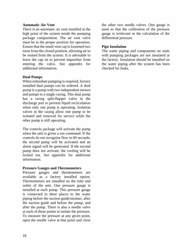
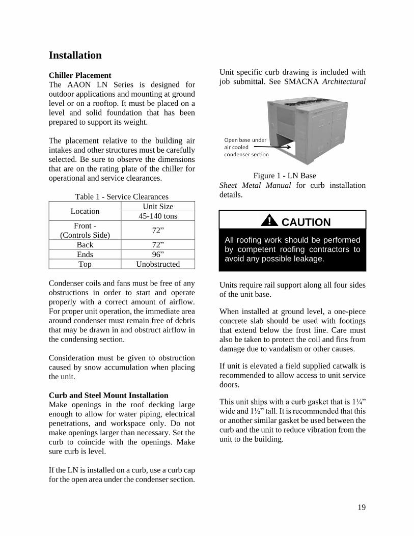
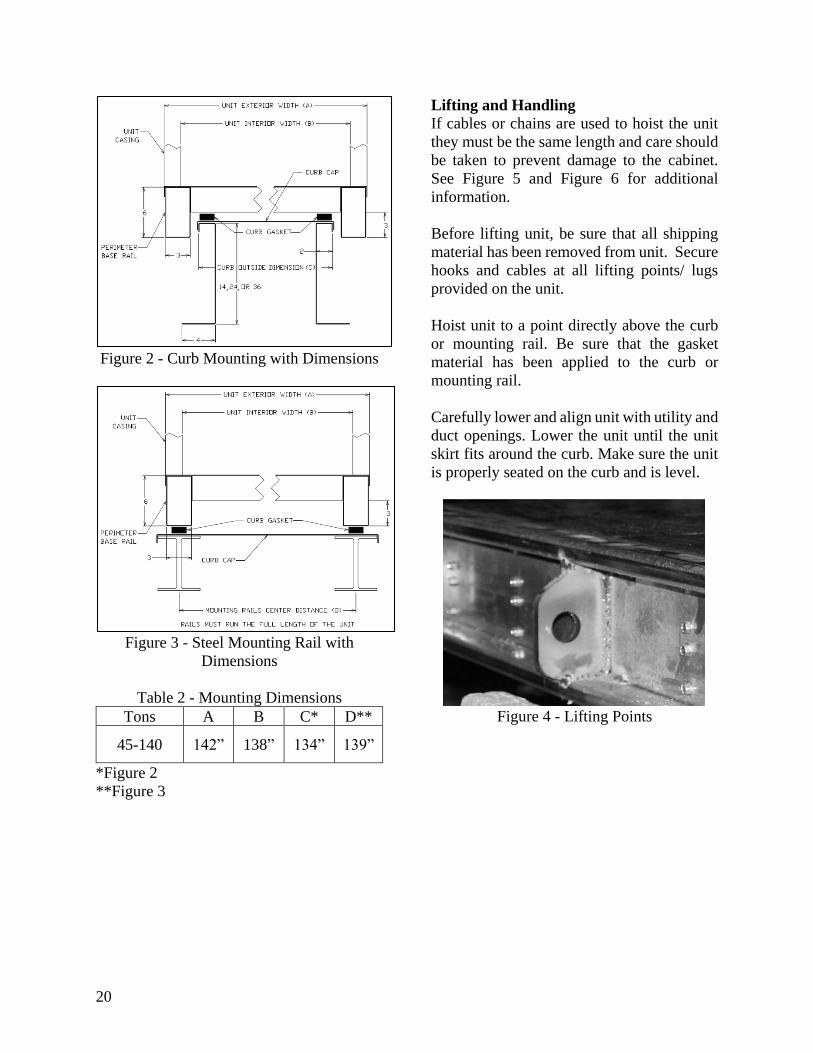
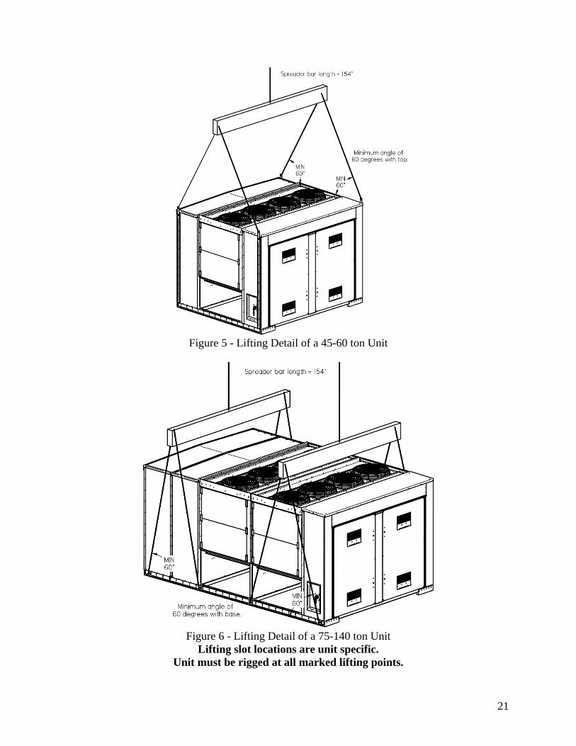
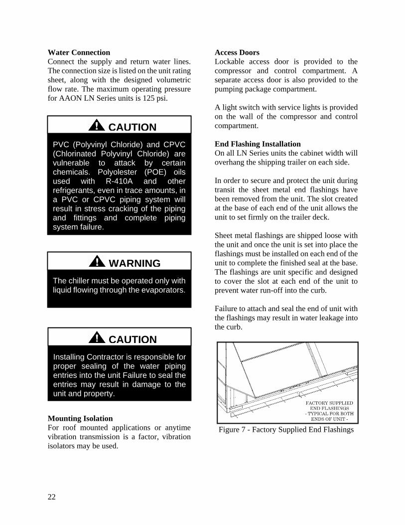
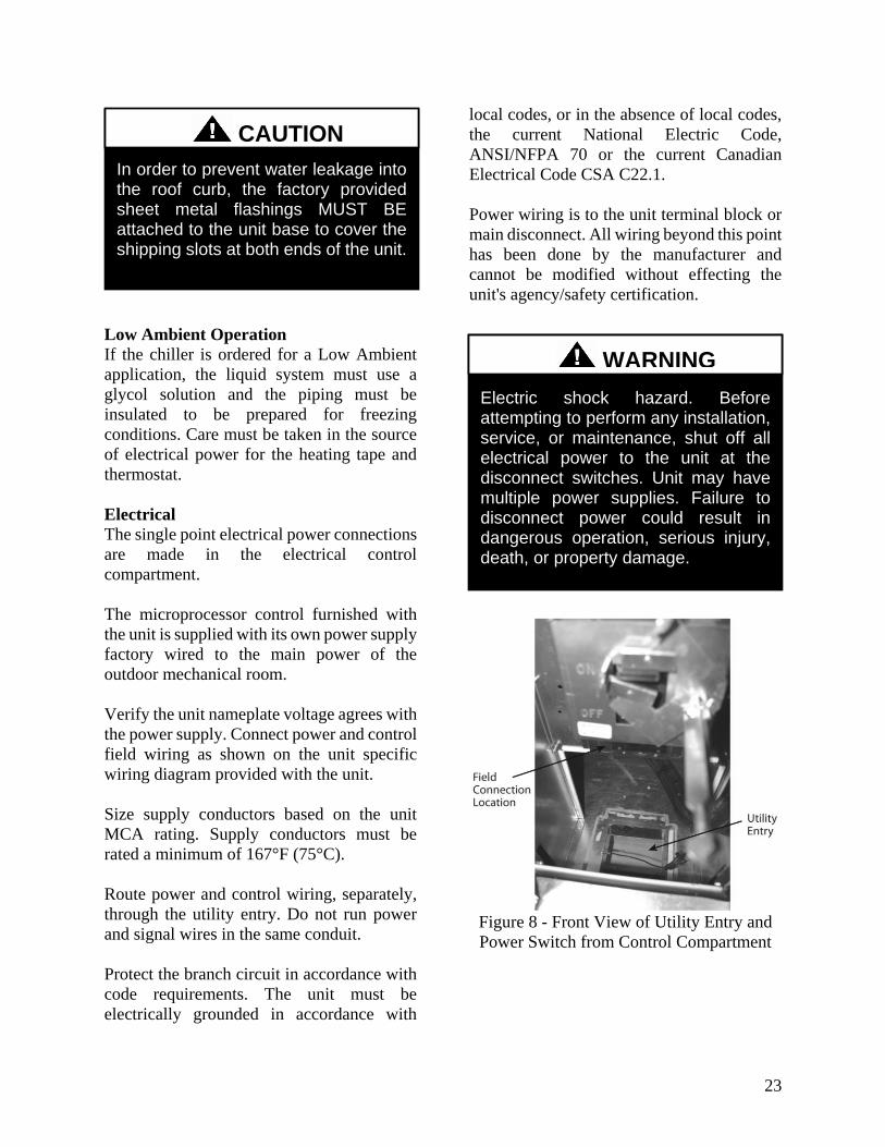
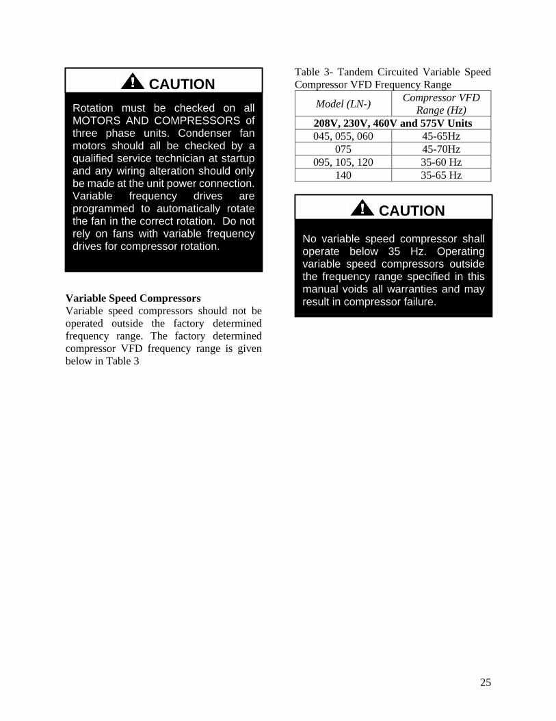
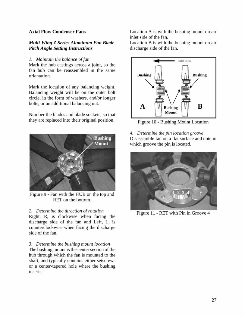
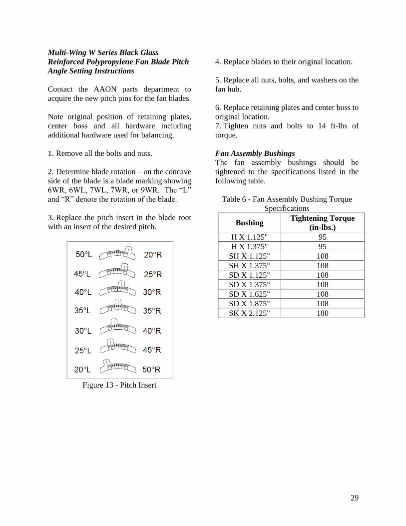
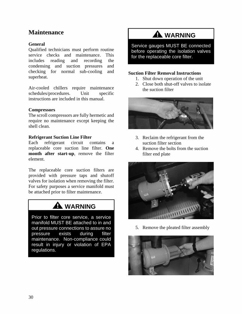
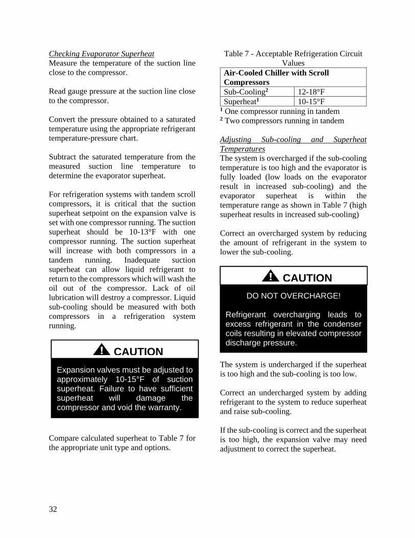
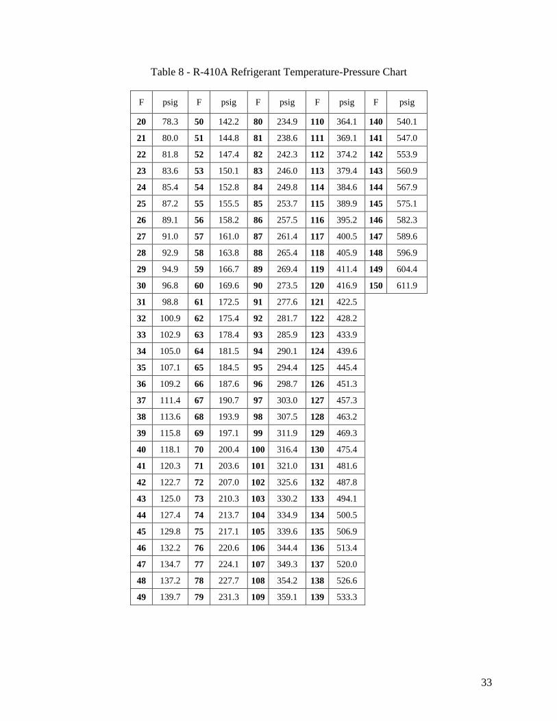
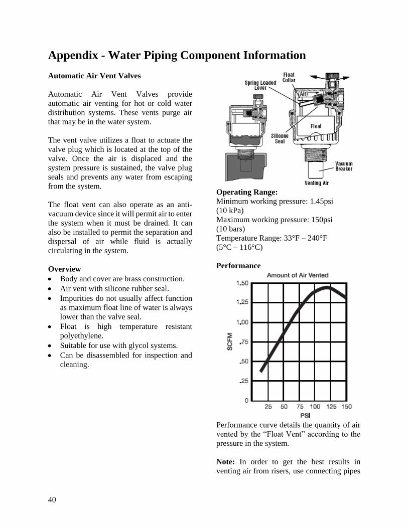
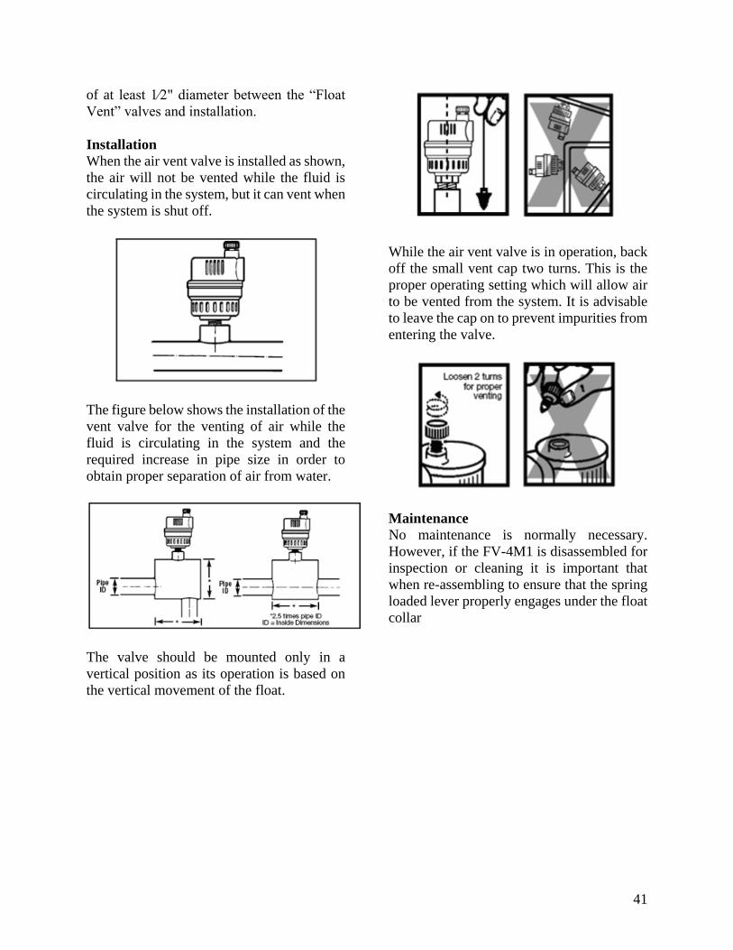
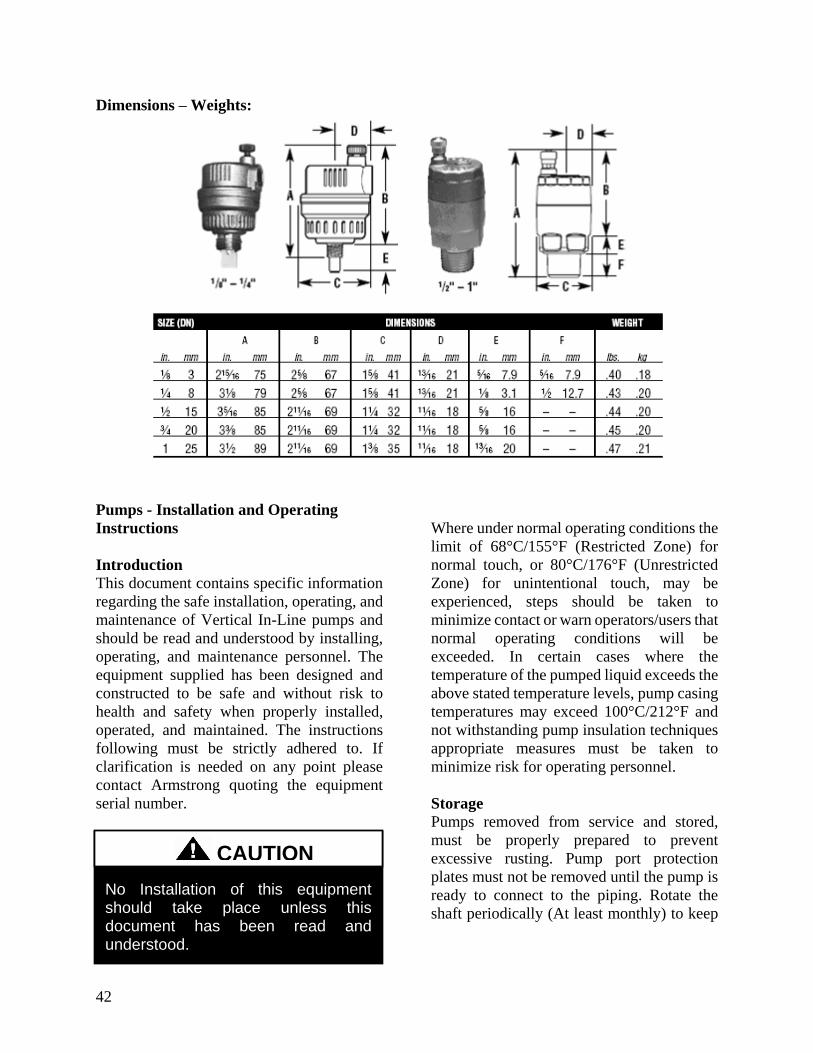
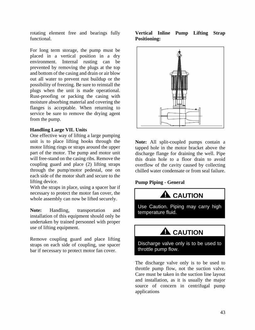
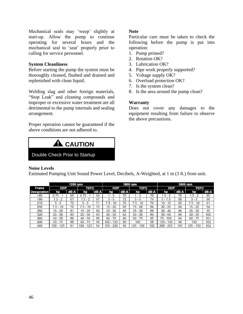
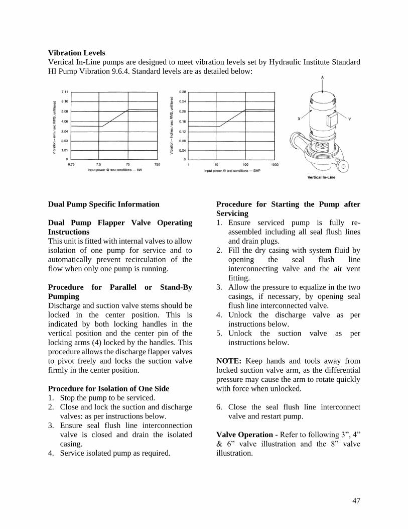
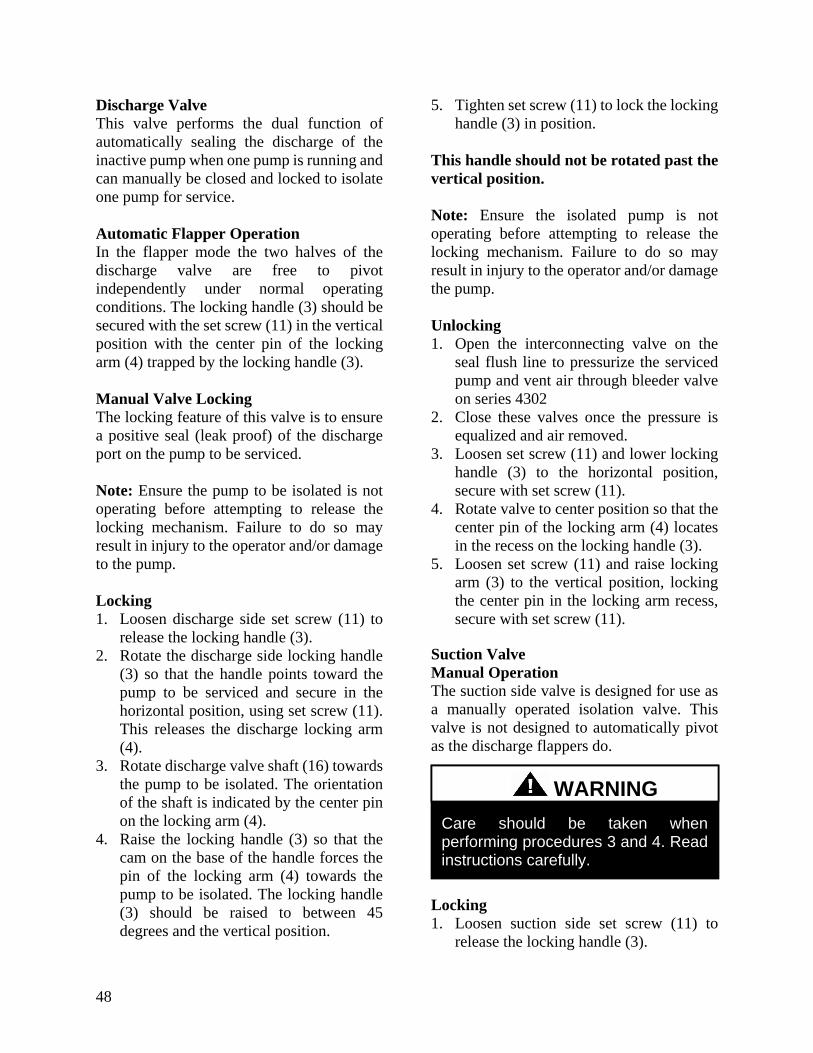
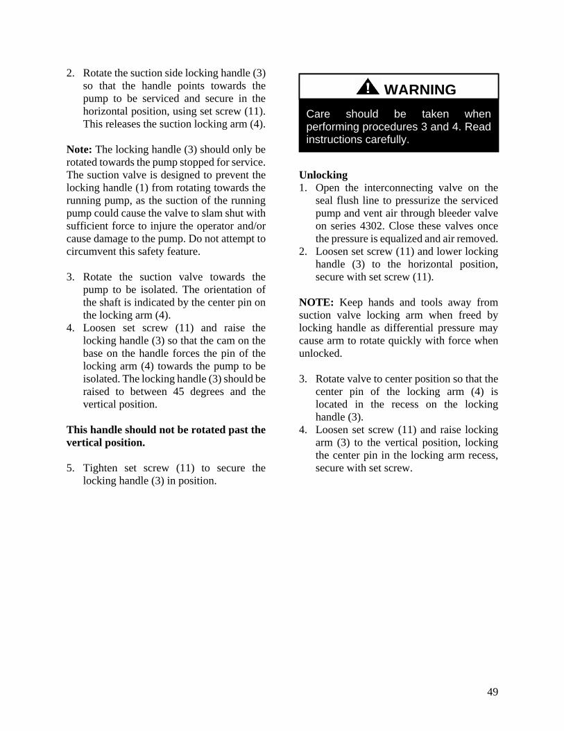
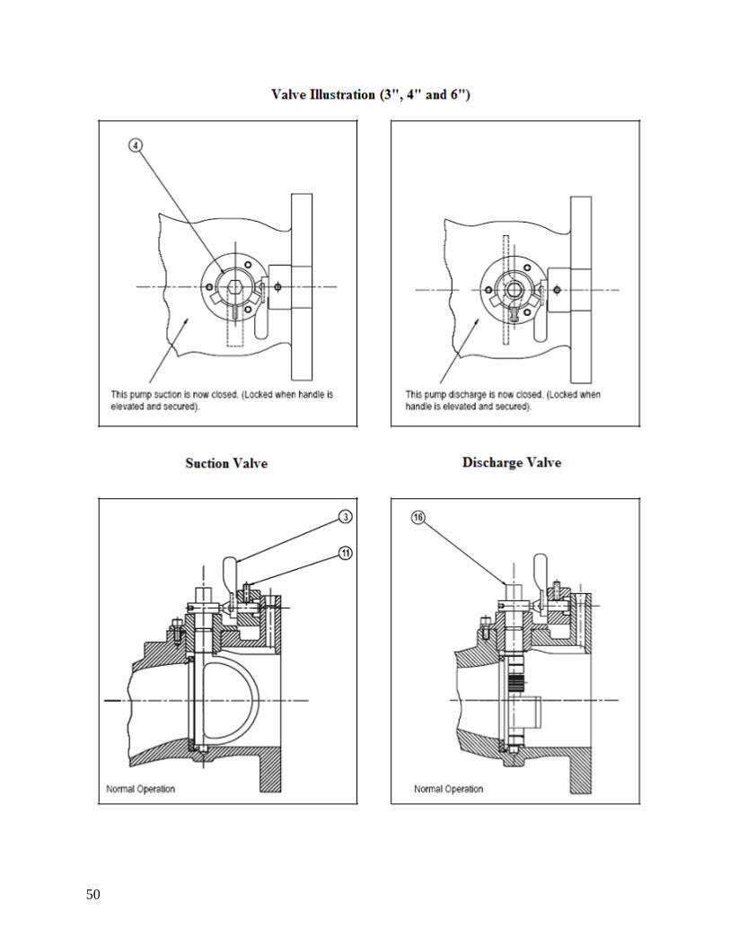
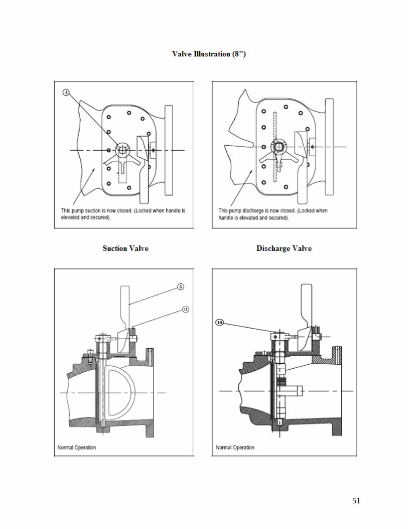
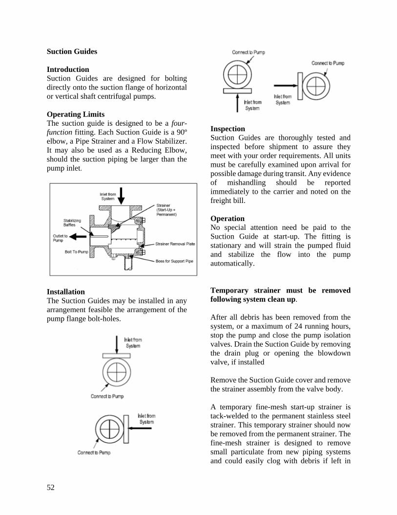
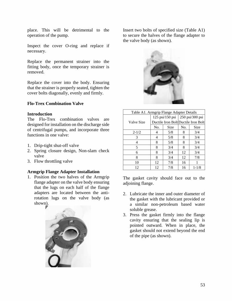
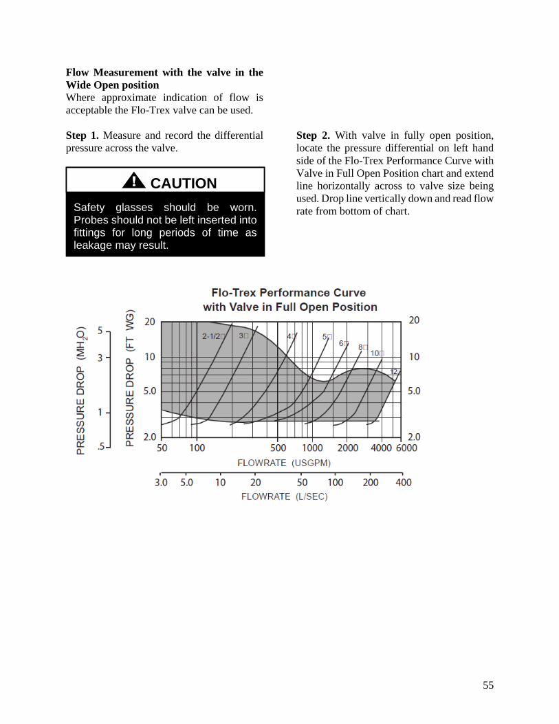
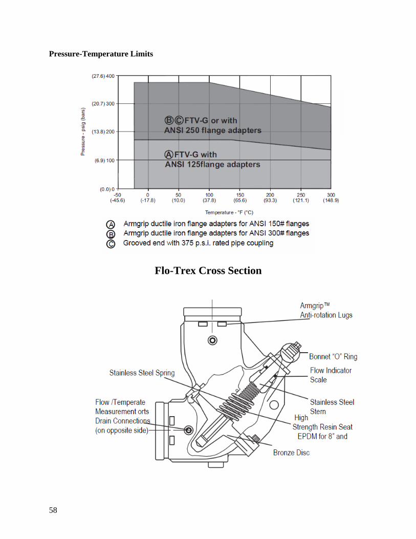
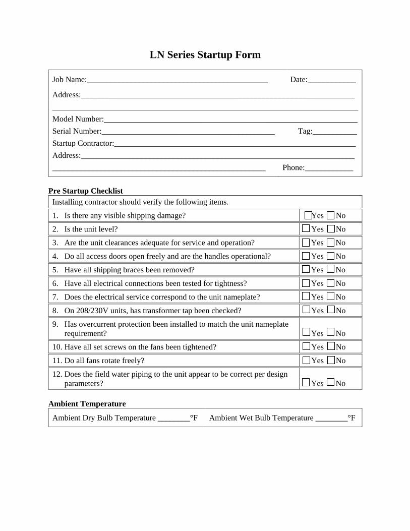
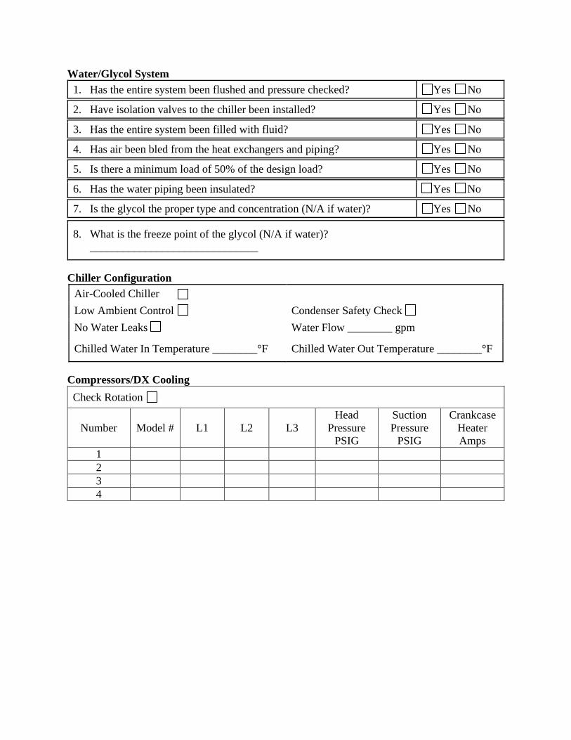
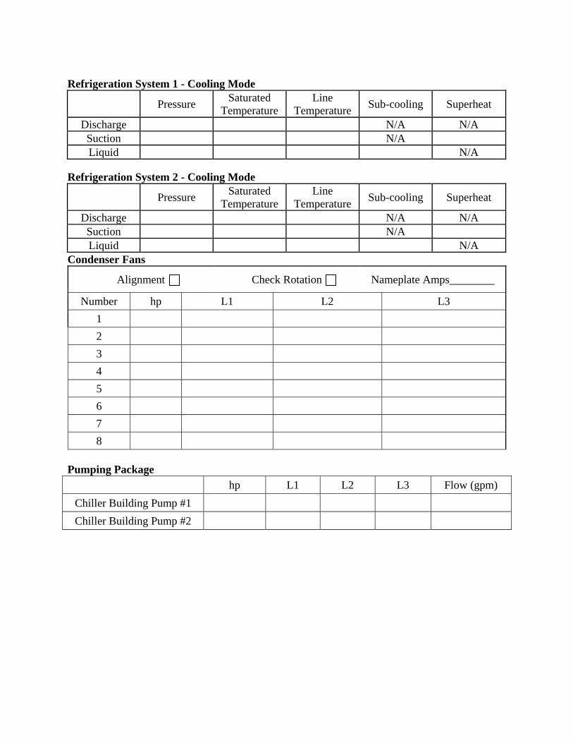
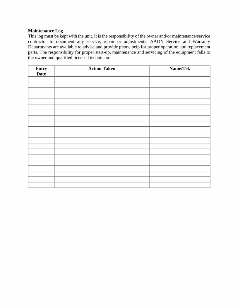