installation manual multi function display model tztl12f
TRANSCRIPT

Installation ManualMULTI FUNCTION DISPLAY
Model TZTL12F/TZTL15F
SAFETY INSTRUCTIONS ................................................................................................ iSYSTEM CONFIGURATION ........................................................................................... iiEQUIPMENT LISTS........................................................................................................ iii
1. MOUNTING..............................................................................................................1-11.1 Mounting Considerations ...................................................................................................1-11.2 Flush Mounting ..................................................................................................................1-21.3 Retrofit Kit for TZTL12F (option) and Front Fixing Panel Kit for TZTL15F (option) ...........1-41.4 Desktop Mounting (option).................................................................................................1-61.5 Installation of Transducers.................................................................................................1-81.6 Installation of Sensors (option) ........................................................................................1-18
2. WIRING....................................................................................................................2-12.1 Interface Connections (Rear of Unit) .................................................................................2-12.2 How to Secure and Waterproof Connections.....................................................................2-22.3 MULTI Cable......................................................................................................................2-22.4 Network Connector ............................................................................................................2-52.5 Video In, Video Out and USB Connections .......................................................................2-52.6 CAN bus (NMEA2000 Connector) .....................................................................................2-62.7 Example NavNet TZtouch2 System Configurations.........................................................2-12
3. HOW TO SET UP THE EQUIPMENT......................................................................3-13.1 How to Set Time Zone, Time Format and Language.........................................................3-33.2 How to Set Units of Measurement .....................................................................................3-43.3 Initial Setup ........................................................................................................................3-53.4 How to Set Up the Radar .................................................................................................3-113.5 How to Set Up the Sounder .............................................................................................3-143.6 Wireless LAN Setting .......................................................................................................3-18
APPENDIX 1 INSTALLATION OF TEMPERATURE SENSORS ............................AP-1
PACKING LISTS ......................................................................................................... A-1OUTLINE DRAWINGS ................................................................................................ D-1INTERCONNECTION DIAGRAM ................................................................................ S-1
www.furuno.comAll brand and product names are trademarks, registered trademarks or service marks of their respective holders.

�������������� ������� ��
������� ���������� �������
����������������������������������
!"#��������!���$
���� ���%�$�&&#!'"'($�)�*��
� � ��� ���������������� �����������������
�� � �� ��������
����� ������������
����� � � �!���"� �!��
�(�(�(�+� �(�(�,�-�+�-

i
SAFETY INSTRUCTIONSThe installer must read the appropriate safety instructions before attempting to install the equipment.
Indicates a potentially hazardous situation which, if not avoided, could result in death or serious injury.
Indicates a potentially hazardous situation which, if not avoided, may result in minor or moderate injury.
WARNING
CAUTION
Warning, Caution Prohibitive Action Mandatory Action
WARNINGELECTRICAL SHOCK HAZARDDo not open the equipment unless totally familiar with electrical circuits.
Only qualified personnel should work inside the equipment.
Turn off the power at the switchboard before beginning the installation.
Fire or electrical shock can result if the power is left on.
CAUTION
Be sure that the power supply is compatible with the voltage rating of the equipment.
Connection of an incorrect power supply can cause fire or damage the equipment.
Use the proper fuse.
Use of an incorrect fuse may damage the equipment.
The front panel is made of glass. Handle it with care.
Injury can result if the glass breaks.
Observe the following compass safe distances to prevent interference to a magnetic compass:
Standard compass
TZTL12F
TZTL15F
Steering compass
0.75 m 0.50 m
0.75 m 0.45 m
(Examples of symbols)
Model
Ground the equipment to prevent electrical shock and mutual interference.
If your vessel is configured with an autopilot system, install an autopilot control unit (or emer-gency autopilot stop button) at each helm station, to allow you to disable the autopilot in an emergency.
If the autopilot cannot be disabled, accidents may result.

ii
SYSTEM CONFIGURATION
Note: When connecting an external monitor to the multi function display, use a monitor whose aspect ratio is the same as that of the multi function display (16:9). The pictures may be stretched or shrunk with a different aspect ratio. Output to an HPD (Hot Plug Detect) monitor is not possible.
CCD Camera
CCD Camera
FI-5002
SC-30
GP-330B
NAVpilot-700
FI-50/70
IF-NMEA2K1/2IF-NMEAFI
12/24 VDC
Event SWExternal BuzzerOperator FitnessPower input for NMEA2000NMEA0183 out
Echo Sounder(BBDS1, DFF series)
Environmental categoryRadar antenna: Exposed to the weatherAll other units: Protected from the weather
AIS Transponder
*1 Radar sensors other than the DRS4DL, DRS4D-NXT and DRS6A X-Class do not requires a power supply unit.*2 FUSION Electronics MS-700 series only (as of 12/2014).*3 Max. 4 NavNet TZtouch2 units (connected via Ethernet hub).
HUB -101
FA-30/50
FAX-30
FUSION-Link Equipment*2
Wide MonitorRemote ControllerMCU-002 or MCU-004
orSD Card Unit SDU-001
Multi Function Display*3 TZTL12F
orTZTL15F
Multi Function Display*3 TZTL12F
orTZTL15F
Transducer
Open Array Radar Sensors
12-24VDC
DRS2D/DRS4D
POWER SUPPLY UNIT*PSU-012/PSU-013
Radome Radar Sensors
DRS4A/DRS6A/DRS12A/DRS25A
POWER SUPPLY
UNIT*PSU-017
For P
SU
-017
DRS4DL
12-24 VDC
DRS4D-NXT
24 VDC
Select one of radomeor open array sensor.
DRS6A X-Class, DRS12A X-Class,DRS25A X-Class
: Standard supply: Optional or local supply
Multi Beam Sonar(DFF-3D)
IP Camera
12-24 VDC
12-24 VDC

EQUIPMENT LISTS
Standard supply
Optional supply
Name Type Code No. Qty Remarks
Multi Function DisplayTZTL12F -
1TZTL15F -
Installation Materials CP19-01810 000-033-430 1 For TZTL12F/15FAccessories FP19-02011 001-337-390 1Spare Parts SP19-00601 001-023-040 1 Fuses (Type: FBG0-A 125V 5A PBF,
Code: 000-155-853-10, 2 pcs.)
Name Type Code No. RemarksJoint Box TL-CAT-012 000-167-140-10 For LAN networkRemote Control Unit MCU-002 -
MCU-004 -SD Card Unit SDU-001 -NMEA2000-Interface Unit IF-NMEA2K1 -
NMEA Data Converter IF-NMEA2K2 -Network HUB HUB-101 -Matching Box MB-1100 000-041-353-00 Required for some
transducers. See next page.
Power Supply Unit PSU-012 000-021-609-00 w/DRS2D/4D/4A/6A/12APSU-013 000-021-610-00 w/DRS25APSU-017 000-022-997-00 w/DRS2D/4D
Rectifier RU-3423 000-030-443-00PR-62 000-013-484-00 100 VAC
000-013-485-00 110 VAC000-013-486-00 220 VAC000-013-487-00 230 VAC
RU-1746B-2 000-030-439-00CAN bus Cable Assy. M12-05BM+05BF-010 001-105-750-10 w/connectors (light), 1 m
M12-05BM+05BF-020 001-105-760-10 w/connectors (light), 2 mM12-05BM+05BF-060 001-105-770-10 w/connectors (light), 6 mM12-05BFFM-010 001-105-780-10 w/connector (light), 1 mM12-05BFFM-020 001-105-790-10 w/connector (light), 2 mM12-05BFFM-060 001-105-800-10 w/connector (light), 6 mCB-05PM+05BF-010 000-167-968-10 w/connectors (heavy), 1 mCB-05PM+05BF-020 000-167-969-10 w/connectors (heavy), 2 mCB-05PM+05BF-060 000-167-970-10 w/connectors (heavy), 6 mCB-05BFFM-010 000-167-971-10 w/connector (heavy), 1 mCB-05BFFM-020 000-167-972-10 w/connector (heavy), 2 mCB-05BFFM-060 000-167-973-10 w/connector (heavy), 6 m
Cable Assy. 02S4147-1 000-141-082 For speed/temp. and temp. sensors
iii

EQUIPMENT LISTS
iv
MEN
C
T
T
ESST
BBR1RFI
J Cable Assy. MJ-A6SPF0016-005C 000-159-689-10 For FAX-30xternal Buzzer OP03-136 000-086-443-00 Buzzer: PKB5-3A40etwork (LAN) Cable MOD-Z072-020+ 001-167-880-10 LAN cable, cross-pair, 2 m
MOD-Z073-030+ 000-167-171-10 LAN cable, straight, 2 pairs, 3 m
MOD-Z072-050+ 001-167-890-10 LAN cable, cross-pair, 5 mMOD-Z072-100+ 001-167-900-10 LAN cable, cross-pair, 10 m
AN bus Connector SS-050505-FMF-TS001 000-168-603-10 Micro style: 3NC-050505-FMF-TS001 000-160-807-10 Mini style: 2, micro style: 1LTWMC-05BMMT-SL8001 000-168-604-10 Micro style, male, termina-
tion resistorLTWMN-05AMMT-SL8001 000-160-508-10 Mini style, male, termination
resistorLTWMC-05BFFT-SL8001 000-168-605-10 Micro style, female,
termination resistorLTWMN-05AFFT-SL8001 000-160-509-10 Mini style, female,
termination resistorFRU-0505-FF-IS 001-077-830-10 w/in-line terminator
ransducer 520-5PSD (*) 000-015-204-00520-5MSD (*) 000-015-212-00525-5PWD (*) 000-146-966-00520-PLD (*) 000-023-680-00525T-BSD (*) 000-023-020-00525T-PWD (*) 000-023-019-00SS60-SLTD/12 (*) 000-023-676-00SS60-SLTD/20 (*) 000-023-677-00525T-LTD/12 (*) 000-023-679-00525T-LTD/20 (*) 000-023-678-0050/200-1T *10M* (*) 000-015-170-00 Matching box MB-1100
required for installation of these transducers.
50B-6 *10M* 000-015-042-0050B-6B *15M* 000-015-043-00200B-5S *10M* 000-015-029-00
riducer 526TID-HDD (*) 000-023-021-00525STID-PWD (*) 000-011-784-00525STID-MSD (*) 000-011-783-00
xtension Cable** C332 10M 001-464-120 10m, for transducerpeed/Temperature ensor
ST-02MSB 000-137-986-01 Thru-hull type, metalST-02PSB 000-137-987-01 Thru-hull type, plastic
emperature Sensor T-04MSB 000-026-893 Thru-hull typeT-04MTB 000-026-894 Transom mount
racket 12 OP19-13 001-337-410-00 For TZTL12Fracket 15 OP19-14 001-337-420-00 For TZTL15Fetrofit Kit For VX2 0.4"
OP19-15 001-337-430-00 For TZTL12F
etrofit Kit For MDF12 OP19-16 001-337-440-00 For TZTL12Front Fixing Panel Kit OP19-17 001-337-450-00 For TZTL15F
nside Hull Kit S 22S0191 001-321-930 not available with bottom discrimination display, w/installation instructions.
Name Type Code No. Remarks

EQUIPMENT LISTS
-
*: Compatible with ACCU-FISH™, Bottom Discrimination and RezBoost™ Enhanced mode. All listed transducers are compatible with RezBoost™ Standard mode.Operator’s Manual OME-44870-* 000-190-069-1* English(* denotes version number)
User’s Guide E42-01403-* 000-179-419-11 MCU-002, EnglishUser’s Guide E42-01509-* 000-191-291-10 MCU-004, English
**: Use of the extension cable may cause the following problems:• Reduced detection ability• Wrong ACCU-FISH™ information (fish length smaller than actual length, fewer fish detections, er-
ror in individual fish detection).• Wrong speed data• No TD-ID recognition
Name Type Code No. Remarks
v

EQUIPMENT LISTS
vi
This page is intentionally left blank.
1. MOUNTING
1.1 Mounting Considerations
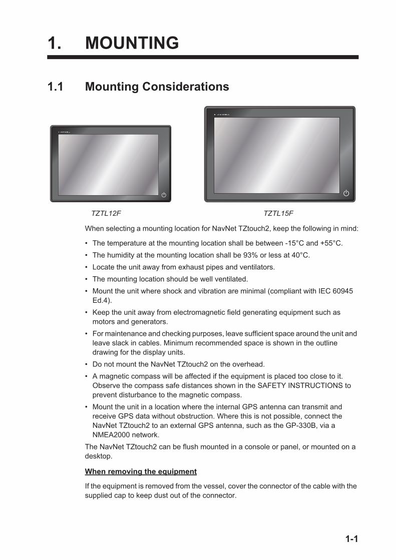
When selecting a mounting location for NavNet TZtouch2, keep the following in mind:
• The temperature at the mounting location shall be between -15°C and +55°C.• The humidity at the mounting location shall be 93% or less at 40°C.• Locate the unit away from exhaust pipes and ventilators.• The mounting location should be well ventilated.• Mount the unit where shock and vibration are minimal (compliant with IEC 60945
Ed.4).• Keep the unit away from electromagnetic field generating equipment such as
motors and generators.• For maintenance and checking purposes, leave sufficient space around the unit and
leave slack in cables. Minimum recommended space is shown in the outline drawing for the display units.
• Do not mount the NavNet TZtouch2 on the overhead.• A magnetic compass will be affected if the equipment is placed too close to it.
Observe the compass safe distances shown in the SAFETY INSTRUCTIONS to prevent disturbance to the magnetic compass.
• Mount the unit in a location where the internal GPS antenna can transmit and receive GPS data without obstruction. Where this is not possible, connect the NavNet TZtouch2 to an external GPS antenna, such as the GP-330B, via a NMEA2000 network.
The NavNet TZtouch2 can be flush mounted in a console or panel, or mounted on a desktop.
When removing the equipment
If the equipment is removed from the vessel, cover the connector of the cable with the supplied cap to keep dust out of the connector.
TZTL15FTZTL12F
1-1

1. MOUNTING
1.2 Flush MountingThere are two methods of flush mount installation. One method uses pilot holes to se-cure the panel at the installation location (Method B), the other method does not use pilot holes (Method A). The merits and demerits of each method is listed in the table below.
Referring to the figure below, select a flat mounting location. Read the installation in-structions before starting. Pay particular attention to the notes; failure to follow these instructions may cause damage to the unit.
Note: Ensure the mounting location is flat, with no indents or protrusions, to allow a secure fit.
1.2.1 Method A: Pilot holes cannot be opened.1. Prepare a cutout in the mounting location using the template (supplied) for the
NavNet TZtouch2.2. Fasten the wing bolts and the wing nuts of the flush mount fixture so that the pro-
tector for screw moves to the flush mount fixture.
Note: Slowly fasten the four wing bolts evenly with your hand. Do not use a tool to fasten the wing bolts. A tool can be used to fasten the wing nuts; use caution so as not to damage the wings or thread.
Method A Method B
Merits No pilot holes are required.Fine adjustment is available.
Shorter process than Method A.
Demerits Longer process than Method A. Pilot holes are required.Fine adjustment is not available.
Flat Curved Bumpy
Wing nut
Wing bolt
Flush mount fixture
Flush mount fixture
Protector for screw
Move to the fixture
1-2
1. MOUNTING
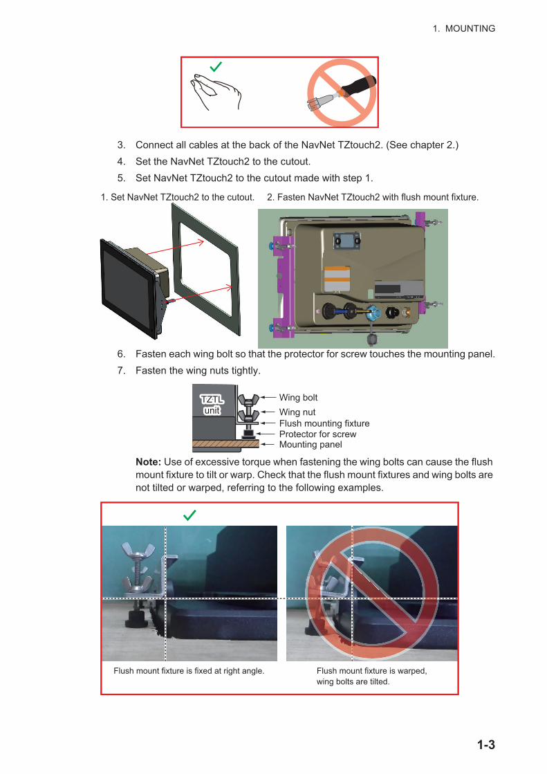
3. Connect all cables at the back of the NavNet TZtouch2. (See chapter 2.)4. Set the NavNet TZtouch2 to the cutout.5. Set NavNet TZtouch2 to the cutout made with step 1.
6. Fasten each wing bolt so that the protector for screw touches the mounting panel.7. Fasten the wing nuts tightly.
Note: Use of excessive torque when fastening the wing bolts can cause the flush mount fixture to tilt or warp. Check that the flush mount fixtures and wing bolts are not tilted or warped, referring to the following examples.
2. Fasten NavNet TZtouch2 with flush mount fixture.
1. Set NavNet TZtouch2 to the cutout.
Wing boltWing nutFlush mounting fixtureProtector for screwMounting panel
TZTL unit
TZTL unit
Flush mount fixture is fixed at right angle. Flush mount fixture is warped, wing bolts are tilted.
1-3

1. MOUNTING
1.2.2 Method B: Pilot holes can be opened.1. Prepare a cutout at the mounting location using the template. (supplied) 2. Remove the flush mount plate from the NavNet TZtouch2. The flush mount plate
is not fastened to the NavNet TZtouch2, and can be easily removed.3. Fit the flush mount plate to the cutout. Fasten the flush mount plate to the pilot
holes of cutout with flat headed self-tapping screws (3 x 20 SUS XM7). Insert the NavNet TZtouch2 to the cutout and fasten with hex bolts (supplied).
1.3 Retrofit Kit for TZTL12F (option) and Front Fixing Panel Kit for TZTL15F (option)When upgrading to the TZTL12F or front-mounting the TZTL15F, use the kit which matches your old equipment. (Refer to the table below for details.)
Note: Remove the flush mounting sponges attached to the back of the NavNet TZ-touch2. Take care that there is no sponge left on the back of the NavNet TZtouch2.
Optional kit Code No. Contains RemarksOP19-15 001-337-430 F Mount Panel A (Code
No.: 100-397-090-10), 5 20 SUS304, 4 pcs. (Code No.: 001-336-820)
For NavNet/NavNet Vx2 displays. (RDP-138/139/149/151) (For TZTL12F)
OP19-16 001-337-440 F Mount Panel B (Code No.: 100-397-100-10), 5 20 SUS304, 4 pcs. (Code No.: 001-336-820)
For NavNet3D MFD12. (For TZTL12F)
OP19-17 001-337-450 F Mount Panel 15 (Code No.: 100-397-600-10), 5 20 SUS304, 4 pcs. (Code No.: 001-336-820)
TZTL15F Front Fixing Panel Kit. (For TZTL15F)
Fit the flush mount plate to the cutout, fasten it to the cutout with flat headed self-tapping screws and insert the NavNet TZtouch2 to the cutout.
Flat headed self-tapping screws 3 x 20 SUS XM-7 (Supplied)
Secure the NavNet TZtouch2 with the hex bolts. (supplied)
Secure the NavNet TZtouch2 with the hex bolts. (supplied)
1-4

1. MOUNTING
1. Prepare a cutout in the mounting location using the template (supplied) for the NavNet TZtouch2.
2. Place the NavNet TZtouch2 unit face-down on a a soft, clean surface.3. Set the F Mount Panel to the NavNet TZtouch2 unit, then using the hex bolts at-
tached to Navnet TZ touch2, fix the F Mount Panel to the unit.4. Set the unit and F Mount Panel into the cutout as shown in the figure to the right,
then use the supplied self-tapping screws (SUS304 4 pcs.), fix the F Mount Panel to the console.
Note: Where the mounting location may be exposed to water (spray or splash), apply a bead of marine sealant around the rear of the F Mount Panel, for waterproofing, before setting the F Mount Panel and unit into the cutout. Wipe the area clean to remove any marine sealant residue and allow time for the marine sealant to dry.
Hex bolt Hex bolt
TZTL unitTZTL unit
Frontmount panel
Console cutout
Console cutout
Self-tapping SUS304 screws
1-5

1. MOUNTING
1.4 Desktop Mounting (option)Follow the appropriate procedure below to mount the NavNet TZtouch2.
Note: Remove the flush mounting sponges attached to the back of the NavNet TZ-touch2. Take care that there is no sponge left on the back of the NavNet TZtouch2.
1.4.1 How to mount the TZTL12FUse the optional kit Bracket12 (contents shown below), for mounting the TZTL12F.
1. Fix the hanger by using self-tapping screws (5 20 SUS304, supplied). The screw locations are indicated in the figure to the right.
2. Place the TZTL12F face-down on a soft, clean surface, then screw the knob bolts into the TZTL12F, leaving a gap of approximately 30 mm.
3. Set the TZTL12F unit to the hanger and tight-en the knob bolts.
Note: When setting the TZTL12F into the hanger, the concave section of the unit and the convex section of the hanger must be aligned.
Type Code ContentsOP19-13 001-337-410 Knob bolt 2 (Code No.: 100-365-900-10), Self-tapping
screws (SUS304 5 20) 4 (Code No.: 000-162-608-10), Hanger 1 (Code No.: 100-397-080-10).
Approx. 30 mm gap
Knob bolts
Hanger
Unit concave Hanger convex
1-6

1. MOUNTING
1.4.2 How to mount the TZTL15FUse the optional kit Bracket15 (contents shown below), for mounting the TZTL15F.
1. Fix the hanger by using self-tapping screws (5 20 SUS304, supplied). The screw locations are indicated in the figure below.
2. Place the TZTL15F face-down on a soft, clean surface, then fit the washers and knob bolts as shown in the figure below, leaving a gap of approximately 30 mm. The washers have a leading edge which must face the unit.
3. Set the TZTL15F unit to the hanger and tighten the knob bolts.
Type Code ContentsOP19-14 001-337-420 Knob bolt 2 (Code No.: 100-346-502-10), Washer 2
(Code No.: 100-076-101-10), Self-tapping screws (SUS304 5 20) 4 (Code No.: 000-162-608-10), Hanger 1 (Code: No.: 001-360-970).
Knob Knob
Washer Washer
Washer leading edge
Hanger
Knob boltKnob bolt
1-7

1. MOUNTING
1.5 Installation of Transducers
1.5.1 How to mount a transducer through the hull
Transducer mounting location
The thru-hull mount transducer provides the best performance of all, since the transducer protrudes from the hull and the effect of air bubbles and turbulence near the hull skin is reduced. If your boat has a keel, the transducer should be at least 30 cm away from it.
The performance of this fish finder is directly related to the mounting location of the transducer, especially for high-speed cruising. The installation should be planned in advance, keeping the length of the transducer cable and the following factors in mind:
• Air bubbles and turbulence caused by movement of the boat seriously degrade the sounding capability of the transducer. The transducer should, therefore, be located in a position where water flow is the smoothest. Noise from the propellers also adversely affects performance and the transducer should not be mounted nearby. The lifting strakes are notorious for creating acoustic noise, and these must be avoided by keeping the transducer inboard of them.
• The transducer must always remain submerged, even when the boat is rolling, pitching or up on a plane at high speed.
• A practical choice would be somewhere between 1/3 and 1/2 of your boat's length from the stern. For planing hulls, a practical location is generally rather far astern, so that the transducer is always in water regardless of the planing attitude.
● Within the wetted bottom area● Deadrise angle within 15°
● Position 1/2 to 1/3 of the hull from stern.● 15 to 30 cm off center line (inside first lifting
strakes.)
DEEP V HULL
HIGH SPEEDV HULL
28
22
120
68
30
24
120
68
87
Unit: mm
520-5PSD 520-5MSD
BOW
1-8

1. MOUNTING
Installation procedure
1. With the boat hauled out of the water, mark the location chosen for mounting the transducer on the bottom of the hull.
2. If the hull is not level within 15° in any direction, fairing blocks made out of teak should be used between the transducer and hull, both inside and outside, to keep the transducer face parallel with the water line. Fabricate the fairing block as shown below and make the entire surface as smooth as possible to provide an undisturbed flow of water around the transducer. The fairing block should be smaller than the transducer itself to provide a channel to divert turbulent water around the sides of the transducer rather than over its face.
3. Drill a hole just large enough to pass the threaded stuffing tube of the transducer through the hull, making sure it is drilled vertically.
4. Apply a sufficient amount of high quality caulking compound to the top surface of the transducer, around the threads of the stuffing tube and inside the mounting hole (and fairing blocks if used) to ensure watertight mounting.
5. Mount the transducer and fairing blocks and tighten the locknut. Be sure that the transducer is properly oriented and its working face is parallel to the waterline.
Note: Do not over-stress the stuffing tube and locknut through excessive tightening, since the wood block will swell when the boat is placed in the water. It is suggested that the nut be tightened lightly at installation and re-tightened several days after the boat has been launched.
Hole for stuffing tube
Saw along slope of hull.
Upper Half
Lower Half
BOW
Flat Hull
Deep-V Hull
Flat Washer
Rubber WasherFairing Block
Hull
HullFlat Washer
Rubber Washer
Cork Washer
1-9

1. MOUNTING
Transducer preparation
Before putting your boat in water, wipe the face of the transducer thoroughly with a detergent liquid soap. This will lessen the time necessary for the transducer to have good contact with the water. Otherwise the time required for complete "saturation" will be lengthened and performance will be reduced.
DO NOT paint the transducer. Performance will be affected.
1.5.2 Transom mount transducerThe optional transom mount transducer is very commonly employed, usually on relatively small I/O or outboard boats. Do not use this method on an inboard motor boat because turbulence is created by the propeller ahead of the transducer.
DO NOT over-tighten screws, to prevent damage to the transducer.
Installation procedure
A suitable mounting location is at least 50 cm away from the engine and where the water flow is smooth.
1. Drill four pilot holes for self-tapping screw (5 20) in the mounting location.2. Coat the threads of the self-tapping screws (5x14) for the transducer with marine
sealant for waterproofing. Attach the transducer to the mounting location with the self-tapping screws.
3. Adjust the transducer position so the transducer faces right to the bottom. If necessary, to improve water flow and minimize air bubbles staying on the transducer face, incline the transducer about 5° at the rear. This may require a certain amount of experimentation for fine tuning at high cruising speeds.
4. Tape the location shown in the figure below.5. Fill the gap between the wedge front of
the transducer and transom with ep-oxy material to eliminate any air spac-es.
6. After the epoxy hardens, remove the tape.
Transom
TransomStrake
Parallel with hull
Mount at the strake.
Less than 10°Less than 10°
Over 10°
5x20
M5x14
5°Taping
Bracket
Transducer
2 to 5°
Epoxy material
Hull
1-10

1. MOUNTING
1.5.3 How to mount a transducer inside the hullThe transducer may also be installed inside the hull on FRP boats. However, this installation method affects the ability to detect the bottom, fish and other objects because the ultrasound pulse is weakened when it passes through the hull.
Note: This mounting method should not be used to mount the transducer that supports the RezBoost™, ACCU-FISH™ and/or bottom discrimination display feature, since performance is greatly degraded.
Necessary tools
The following tools are required:
Remarks on installation
Installation procedure
The attenuation of the ultrasound pulse varies with the thickness of the hull. Select a location where attenuation is the lowest.
1. Select 2-3 locations considering the four points mentioned below.
2. Decide the most suitable site from the locations selected.1) Connect the power cable and transducer cable to the display unit.
• Sandpaper (#100)• Marine sealant• Water-filled plastic bag
• Do the installation with the ship moored at a dock, etc. The water depth should be 6.5 to 32 feet (2 to 10 meters).
• Turn off the engine.• Do not power the unit with the transducer in the air, to prevent damage to the
transducer.• Do not use this method on a double layer hull.• Before attaching the transducer to the hull, check that the site is suitable, by following
steps 1 to 3 in the installation procedure below.
• Mount the transducer at a location 1/2 to 1/3 of the length of your boat from the stern.
• The mounting location is between 15 to 50 cm from the centerline of the hull.• Do not place the transducer over hull struts or ribs which run under the hull.• Avoid a location where the rising angle of the hull exceeds 15°, to minimize the
effect of the boat's rolling.
1/3
1/2Centerline
Transducer mounting location
50 cm
50 cm15 cm15 cm
1-11

1. MOUNTING
2) Put the transducer into water-filled plastic bag. Press the transducer against the chosen site.
3) Tap (power switch) to turn the power on.4) After the startup procedure completes (approx.
90 seconds), the last used display appears. Tap the [Home] icon ( ) to show the home screen and display mode settings. See section 3.3 for how to use the menu.
5) Drag the menu to show [Sounder] in the menu, then tap [Sounder].6) Drag the [Sounder] menu to show the [SOUNDER INITIAL SETUP] menu.7) Tap [Fish Finder Source].8) Confirm the available fish finder from the list of available sounders, then tap
the appropriate fish finder. For the purpose of this example, the default setting [TZTL] (internal sounder) is selected as the source.
9) Tap the [<] icon to return to the [Sounder] menu10) Drag the [Sounder] menu to show the [SOUNDER INITIAL SETUP] menu.11) Tap [Transducer Setup].12) Tap [Transducer Setup Type].13) Tap [Model], then tap the [<] icon to return to [Transducer Setup] menu.14) Tap [Model Number], drag the menu to show your transducer model, then tap
the transducer model number.15) Tap the [<] icon twice to return to the [Sounder] menu, then drag the [Sounder]
to show the [SOUNDER INITIAL SETUP] menu.16) At the [Transmission Power] menu item, set the transmission power to a level
of [2].17) Drag the menu to show [Sounder Transmit], then tap [Sounder Transmit].
Check if the bottom echo appears on the right side of the screen, in the display area.If no bottom echo appears, repeat the procedure unit a suitable location is found.
3. Remove the transducer from the plastic bag and wipe the face of transducer with a cloth to remove water and any foreign material. Lightly roughen the face with #100 sandpaper. Also, use the sandpaper to roughen the inside of the hull where the transducer is to be mounted.
4. Wipe off any sandpaper dust from the face of the transducer.
Plastic bag
Water
Hull plate
1-12
1. MOUNTING
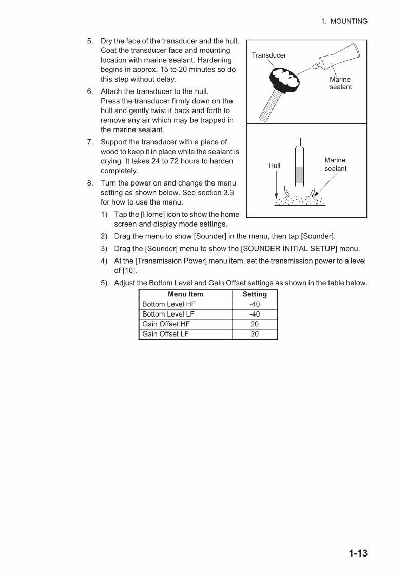
5. Dry the face of the transducer and the hull. Coat the transducer face and mounting location with marine sealant. Hardening begins in approx. 15 to 20 minutes so do this step without delay.
6. Attach the transducer to the hull. Press the transducer firmly down on the hull and gently twist it back and forth to remove any air which may be trapped in the marine sealant.
7. Support the transducer with a piece of wood to keep it in place while the sealant is drying. It takes 24 to 72 hours to harden completely.
8. Turn the power on and change the menu setting as shown below. See section 3.3 for how to use the menu.1) Tap the [Home] icon to show the home
screen and display mode settings.2) Drag the menu to show [Sounder] in the menu, then tap [Sounder].3) Drag the [Sounder] menu to show the [SOUNDER INITIAL SETUP] menu.4) At the [Transmission Power] menu item, set the transmission power to a level
of [10].5) Adjust the Bottom Level and Gain Offset settings as shown in the table below.
Menu Item SettingBottom Level HF -40Bottom Level LF -40Gain Offset HF 20Gain Offset LF 20
Transducer
Marine sealant
HullMarine sealant
1-13
1. MOUNTING
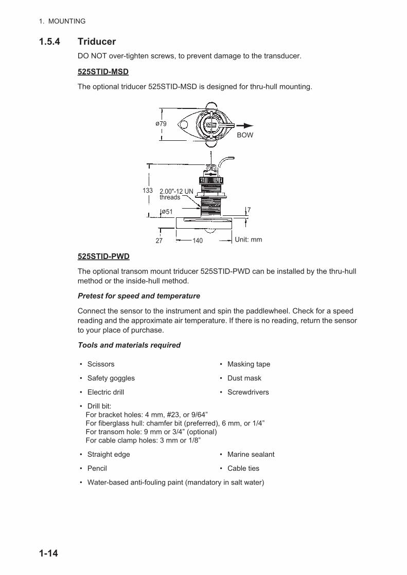
1.5.4 TriducerDO NOT over-tighten screws, to prevent damage to the transducer.
525STID-MSD
The optional triducer 525STID-MSD is designed for thru-hull mounting.
525STID-PWD
The optional transom mount triducer 525STID-PWD can be installed by the thru-hull method or the inside-hull method.
Pretest for speed and temperature
Connect the sensor to the instrument and spin the paddlewheel. Check for a speed reading and the approximate air temperature. If there is no reading, return the sensor to your place of purchase.
Tools and materials required
• Scissors • Masking tape
• Safety goggles • Dust mask
• Electric drill • Screwdrivers
• Drill bit: For bracket holes: 4 mm, #23, or 9/64” For fiberglass hull: chamfer bit (preferred), 6 mm, or 1/4” For transom hole: 9 mm or 3/4” (optional) For cable clamp holes: 3 mm or 1/8”
• Straight edge • Marine sealant
• Pencil • Cable ties
• Water-based anti-fouling paint (mandatory in salt water)
ø79
133 2.00"-12 UN threads
ø51 7
27 140 Unit: mm
BOW
1-14
1. MOUNTING
Mounting location
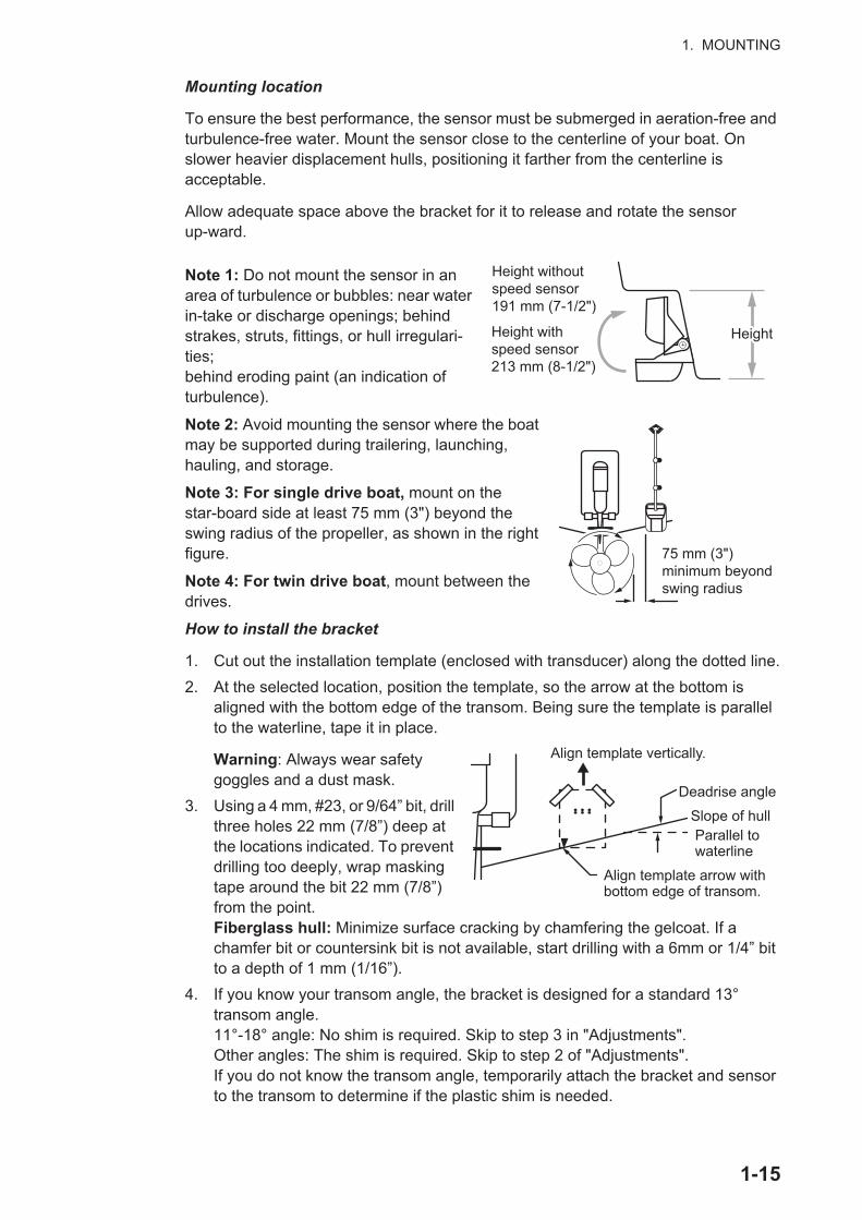
To ensure the best performance, the sensor must be submerged in aeration-free and turbulence-free water. Mount the sensor close to the centerline of your boat. On slower heavier displacement hulls, positioning it farther from the centerline is acceptable.
Allow adequate space above the bracket for it to release and rotate the sensor up-ward.
Note 1: Do not mount the sensor in an area of turbulence or bubbles: near water in-take or discharge openings; behind strakes, struts, fittings, or hull irregulari-ties; behind eroding paint (an indication of turbulence).
Note 2: Avoid mounting the sensor where the boat may be supported during trailering, launching, hauling, and storage.
Note 3: For single drive boat, mount on the star-board side at least 75 mm (3") beyond the swing radius of the propeller, as shown in the right figure.
Note 4: For twin drive boat, mount between the drives.
How to install the bracket
1. Cut out the installation template (enclosed with transducer) along the dotted line.2. At the selected location, position the template, so the arrow at the bottom is
aligned with the bottom edge of the transom. Being sure the template is parallel to the waterline, tape it in place.
Warning: Always wear safety goggles and a dust mask.
3. Using a 4 mm, #23, or 9/64” bit, drill three holes 22 mm (7/8”) deep at the locations indicated. To prevent drilling too deeply, wrap masking tape around the bit 22 mm (7/8”) from the point.Fiberglass hull: Minimize surface cracking by chamfering the gelcoat. If a chamfer bit or countersink bit is not available, start drilling with a 6mm or 1/4” bit to a depth of 1 mm (1/16”).
4. If you know your transom angle, the bracket is designed for a standard 13° transom angle.11°-18° angle: No shim is required. Skip to step 3 in "Adjustments".Other angles: The shim is required. Skip to step 2 of "Adjustments". If you do not know the transom angle, temporarily attach the bracket and sensor to the transom to determine if the plastic shim is needed.
Height without speed sensor 191 mm (7-1/2")
Height with speed sensor 213 mm (8-1/2")
HeightHeight
75 mm (3") minimum beyond swing radius
Align template vertically.
Deadrise angle
Slope of hullParallel to waterline
Align template arrow with bottom edge of transom.
1-15

1. MOUNTING
5. Using the three #10 x 1-1/4” self-tapping screws, temporarily screw the bracket to the hull. DO NOT tighten the screws completely at this time. Follow the step 1-4 in "How to attach the sensor to the bracket", before proceeding with "Adjustments".
Adjustments
1. Using a straight edge, sight the underside of the sensor relative to the underside of the hull. The stern of the sensor should be 1-3 mm (1/16-1/8”) below the bow of the sensor or parallel to the bottom of the hull.Note: Do not position the bow of the sensor lower than the stern because aeration will occur.
2. To adjust the sensor's angle relative to the hull, use the tapered plastic shim provided. If the bracket has been temporarily fastened to the transom, remove it. Key the shim in place on the back of the bracket.2°-10° transom angle (stepped transom and jet boats): Position the shim with the tapered end down.19°-22° transom angle (small aluminum and fiberglass boats): Position the shim with the tapered end up.
3. If the bracket has been temporar-ily fastened to the transom, re-move it. Apply a marine sealant to the threads of the three #10 x 1-1/4” self-tapping screws to prevent water seeping into the transom. Screw the bracket to the hull. Do not tighten the screws completely at this time.
4. Repeat step 1 to ensure that the angle of the sensor is correct.Note: Do not position the sensor farther into the water than necessary to avoid increasing drag, spray, and water noise and reducing boat speed.
5. Using the vertical adjustment space on the bracket slots, slide the sensor up or down to provide a projec-tion of 3 mm (1/8”). Tighten the screws.
2º-10º transom
angle
11º transom angle NO SHIM
19º-22º transom
angle
shim with taper down
shim with taper up
YES YES YES
parallel parallel parallel
12º-18º transom angle NO SHIM
NO NOYES
angle reversed
slight angle
angle too steep
Cable cover
Cable clamp
50 mm (2")
Hull projection 3 mm (1/8")
1-16

1. MOUNTING
How to attach the sensor to the bracket
1. If the retaining cover near the top of the bracket is closed, open it by depressing the latch and rotating the cover downward.
2. Insert the sensor's pivot arms into the slots near the top of the bracket.
3. Maintain pressure until the pivot arms click into place.
4. Rotate the sensor downward until the bottom snaps into the bracket.
5. Close the retaining cover to prevent the accidental release of the sensor when your boat is underway.
How to route the cable
Route the sensor cable over the transom, through a drain hole, or through a new hole drilled in the transom above the waterline.
Never cut the cable or remote the connector; this will void the warranty. Always wear safety goggles and a dust mask.
1. If a hole must be drilled, choose a location well above the waterline. Check for obstructions such as trim tabs, pumps, or wiring inside the hull. Mark the location with a pencil. Drill a hole through the transom using a 19 mm or 3/4” bit (to accommodate the connector).
2. Route the cable over or through the transom.3. On the outside of the hull secure the cable against the transom using the cable
clamps. Position a cable clamp 50 mm (2") above the bracket and mark the mounting hole with a pencil.
4. Position the second cable clamp halfway between the first clamp and the cable hole. Mark this mounting hole.
5. If a hole has been drilled in the transom, open the appropriate slot in the transom cable cover. Position the cover over the cable where it enters the hull. Mark the two mounting holes.
6. At each of the marked locations, use a 3 mm or 1/8” bit to drill a hole 10 mm (3/8”) deep. The prevent drilling too deeply, wrap masking tape around the bit 10 mm (3/8”) from the point.
7. Apply marine sealant to the threads of the #6 x 1/2” self-tapping screw to prevent water from seeping into the transom. If you have drilled a hole through the transom, apply marine sealant to the space around the cable where it passes through the transom.
8. Position the two cable clamps and fasten them in place. If used, push the cable cover over the cable and screw it in place.
9. Route the cable to the display unit being careful not to tear the cable jacket when passing it though the bulkhead(s) and other parts of the boat. To reduce electrical interference, separate the sensor cable from other electrical wiring and "noise" sources. Coil any excess cable and secure it in place with zip-ties to prevent damage.
Step 1 Step 2
Step 3Step 4
LatchPivot arm
Slot Retaining cover
1-17

1. MOUNTING
1.6 Installation of Sensors (option)
1.6.1 Speed/temperature sensors ST-02MSB, ST-02PSBThe speed/temperature sensors (ST-02MSB, ST-02PSB) are designed for thru-hull mounting. Install them as shown in this section.
Mounting considerations
Select a suitable mounting location, considering the following:
Mounting procedure
1. Dry-dock the boat.2. Make a hole of approx. 51 mm diame-
ter in the mounting location.3. Unfasten the locknut and remove the
sensor section.4. Apply marine sealant to the flange of
the sensor. The height of the coat should be approx. 6 mm.
5. Pass the sensor casing through the hole.
6. Face the notch on the sensor toward boat's bow and tighten the flange.
7. Set the sensor section to the sensor casing and tighten the locknut.
8. Launch your boat and check for water leakage around the sensor.
1.6.2 Temperature sensors T-04MSB and T-04MTBFor installation instructions for T-04MSB and T-04MTB sensors, see "INSTALLATION OF TEMPERATURE SENSORS" on page AP-2.
• Select a location where the transducer will not be damaged in trailering, launching, hauling, and storage.
• Select a mid-boat flat position. The sensor does not have to be installed perfectly perpendicular.
• Select a location in the forward direction viewing from the drain hole, to allow for circulation of cooling water.
• Select a location away from water flow from keel, water discharge pipe, etc.• Vibration at the location shall be minimal.• Do not install fore of the transducer of a fish finder, to prevent disturbance (and loss of
performance) to the fish finder.
Locknut
123
Face "notch" toward bow.
Flange nut51
Brimø77
Coat with marine sealant.
Unit: mm
1-18

2. WIRING
2.1 Interface Connections (Rear of Unit)
Ground wire(Local supply, IV-8sq.)*1
Power cableMJ-A3SPF0019-035C cable (Supplied, 3.5 m)
Transducer cable*3
Rear of TZTL12F/TZTL15FRear of TZTL12F/TZTL15F
Video outVideo outVideo In 1Video In 1
Video In 2Video In 2
USB 2.0USB 2.0
NetworkNetwork NMEA2000NMEA2000
Composite 1Composite 1
Composite 1
Composite 2Composite 2
Composite 2
*1: Lay the ground wire away from this unit’s power cable.
*2: Install the EMI core as close to the TZTL side of the lead end as possible.
TO: Transducer
TO: 12/24 VDC
TO: Ship’s groundEMI Core*2EMI Core*2
MULTI cableMULTI cable
*3: Use of the extension cable (C332 10M) may cause the following problems: - Reduced detection ability- Wrong ACCU-FISH™ information (fish length smaller than actual length, fewer fish detections, error in individual fish detection).- Wrong speed data- No TD-ID recognition
2-1

2. WIRING
2.2 How to Secure and Waterproof ConnectionsWhere the unit is exposed to water spray or moisture, Video out, USB, Video In, NMEA2000, LAN network and Multi cable connections to the NavNet TZtouch2 must have at least IPx2 waterproof rating.
All unused cable ends should be covered for protection.
2.3 MULTI CableUse the MULTI cable for the event switch, external buzzer, contact alarm and to supply power to the CAN bus. The connector has 11 wires. Use the table below for reference when connecting the MULTI cable.
Wire color Function Remark (Port No.)White NMEA-TD-A
NMEA0183 outputBlue NMEA-TD-BGray EXT_BUZZER External buzzer ON/OFFRed +12 V External buzzer power (12 V)Orange EVENT_SW Event switch (MOB, etc.)Black GND GroundingPurple ALARM_CONTACT_1
Alarm signal (no polarity)Brown ALARM_CONTACT_2White/Red CAN_NET-S CAN bus power input (+15 V)White/Black CAN_NET-C CAN bus power input (0 V)Black Braided Shield For grounding the connector
Wrap connection in vulcanizing tape for waterproofing.
Wrap vulcanizing tape in vinyl tape, then secure tape ends with cable ties.
Securing and waterproofing connections
Securing and protecting unused cable connectors
1. Cover the cable connector with vinyl tape
2. Wrap the connector, covering approx. 50 mm of the connecting cable. Bind the tape end with a cable tie to prevent the tape from unraveling.
Step 1
Step 1
Step 2
Step 2
1. Wrap the connection point in vulcanizing tape, covering at approximately 30 mm of the connecting cable.
2. Wrap the vulcanizing tape with vinyl tape, covering approx. 50 mm of the connecting cable.Bind the tape ends with cable ties to prevent the tape from unraveling.
2-2

2. WIRING
2.3.1 How to isolate and secure unused wires1. Cut the outer and inner sheaths lengthwise. Take care not to cut the wires.2. Fold back the outer sheath, then fold back the inner sheath, covering the outer
sheath.3. Individually isolate unused wires using vinyl tape, then secure the unused wires
as shown in the figure below.
2.3.2 How to set up NMEA0183 data outputNote: To set up data input from NMEA0183 equipment, see "NMEA0183 equipment data input" on page 2-9.
1. Cut the XH connector at the end of the external buzzer cable to an appropriate length for your installation.
2. Referring to the figure below, place heat shrink tubes on the wires, then solder the connection point.
3. Move the heat shrink tubes to the soldered connection, then apply heat to the tubes.
4. Isolate and secure unused wires as shown in paragraph 2.3.1.
5. Tap the [Home] icon ( ) to show the home screen and display mode settings.
6. Tap [Settings], then drag the menu to show [Initial Setup]. Tap [Initial Setup].7. Drag the menu to show [NMEA0183 Output], then tap [NMEA0183 Output].8. Tap [Baud Rate] to set the output baud rate. Available options are [4,800], [9,600]
and [38,400]. Tap the appropriate setting then tap the icon.
9. Tap [NMEA-0183 Version] to set the version. Available options are [1.5], [2.0] and [3.0]. Tap the appropriate setting then tap the icon.
10. Select the appropriate sentences to output, then tap the flipswitch to set the sentence to [ON].
11. Tap the [Close] icon at the top right of the screen to close the menus.
Isolate unused wires with vinyl tape Secure unused wires to outer sheath with vinyl tape
Outer sheathOuter sheath Outer sheathOuter sheath
Inner sheath Inner sheath
Solder the connection point, then set the heat shrink tube to the cores.
Secure unused wires with tape here
Multi cable
TD-B wire (blue)
RD-B wire
TD-A wire (white) RD-A wire
NMEA0183 equipmentNMEA0183 equipment
2-3
2. WIRING
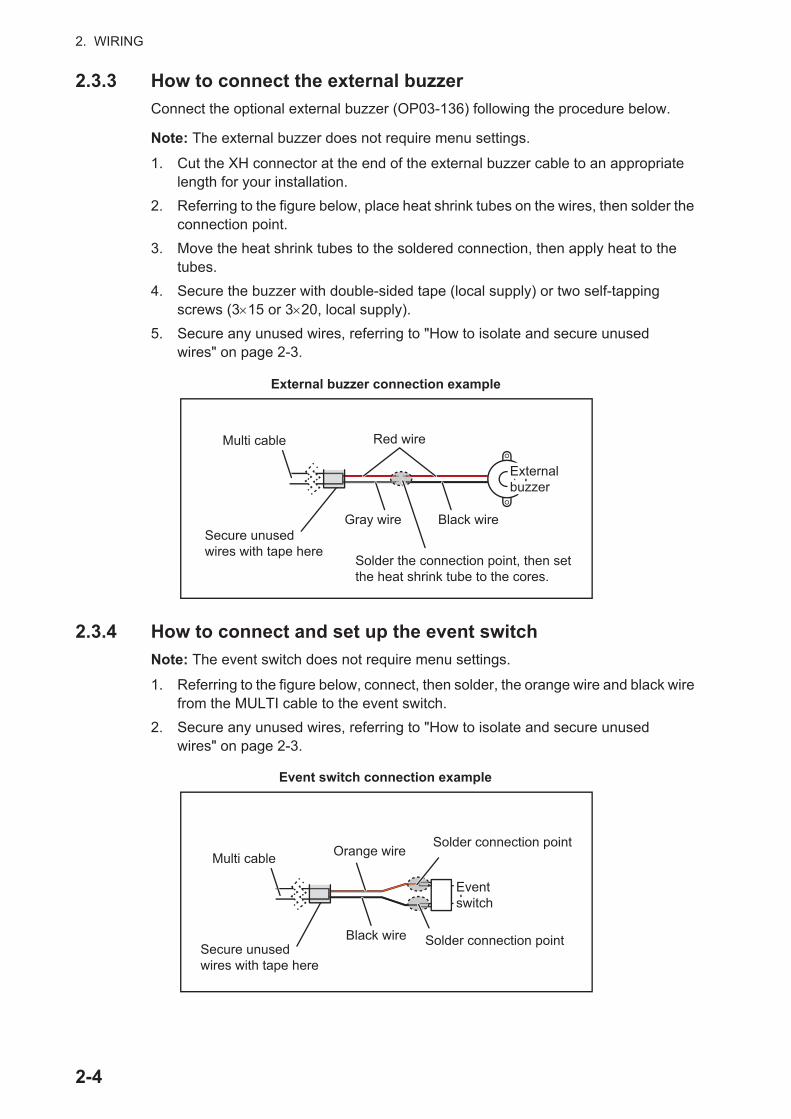
2.3.3 How to connect the external buzzerConnect the optional external buzzer (OP03-136) following the procedure below.
Note: The external buzzer does not require menu settings.
1. Cut the XH connector at the end of the external buzzer cable to an appropriate length for your installation.
2. Referring to the figure below, place heat shrink tubes on the wires, then solder the connection point.
3. Move the heat shrink tubes to the soldered connection, then apply heat to the tubes.
4. Secure the buzzer with double-sided tape (local supply) or two self-tapping screws (3 15 or 3 20, local supply).
5. Secure any unused wires, referring to "How to isolate and secure unused wires" on page 2-3.
2.3.4 How to connect and set up the event switchNote: The event switch does not require menu settings.
1. Referring to the figure below, connect, then solder, the orange wire and black wire from the MULTI cable to the event switch.
2. Secure any unused wires, referring to "How to isolate and secure unused wires" on page 2-3.
Red wire
Gray wire Black wire
Solder the connection point, then set the heat shrink tube to the cores.
Secure unused wires with tape here
External buzzerExternal buzzer
External buzzer connection example
Multi cable
Black wire
Solder connection point
Solder connection point
Event switchEvent switch
Secure unused wires with tape here
Orange wireMulti cable
Event switch connection example
2-4

2. WIRING
2.3.5 How to connect operator fitness to a BR-500Note: Operator fitness does not require adjustments in the menu.
1. Referring to the figure below, place heat shrink tubes on the wires, then solder the connection point. (Refer to the BR-500 installer’s manual for the appropriate wires at the BR-500.)
2. Move the heat shrink tubes to the soldered connection, then apply heat to the tubes.
3. Secure any unused wires, referring to "How to isolate and secure unused wires" on page 2-3.
2.4 Network ConnectorLike previous NavNet series equipment, the TZTL12F and TZTL15F may share Radar and Fish Finder images, and other information, across a TCP/IP Ethernet connection. Up to four NavNet TZtouch2 units may be connected to the same network at one time. Both the TZTL12F and TZTL15F are equipped with a network connector (RJ45).
IP cameras are network devices that connect directly to a HUB. Up to four IP cameras can be connected to one NavNet TZtouch2 network. At this time, only AXIS IP cam-eras that support MPEG4 video are functional in the network. For more details, see the operator’s manual for AXIS models.
2.5 Video In, Video Out and USB ConnectionsThe composite 2 bundle, at the rear of the unit (See the figure on page 2-1), contains connection leads for Video In (two leads), one HDMI output and one USB port.
Analog video input
The NavNet TZtouch2 can use regular analog video inputs (PAL or NTSC) that connect to the NavNet TZtouch2 directly via the Video Input 1/2 connectors. Analog video can be viewed only on the equipment where the source is connected.
Additionally FLIR cameras may be connected to the NavNet TZtouch2. Connect the Video Out cable from the camera to the Video In (1 or 2) cable on the NavNet TZtouch2.
Note: Some camera models may require an adapter for connection.
Solder the connection point, then set the heat shrink tube to the cores.
Secure unused wires with tape here
Multi cable
Brown
Purple
BR-500BR-500
2-5

2. WIRING
Cameras may be set up using the appropriate menu item on the [Camera] menu, accessed from the [Settings] menu. For details on camera setup, see the operator’s manual (OME-44870-x)
Video out (external HDMI monitor)
A HDMI monitor can be connected to the NavNet TZtouch2 to repeat the screen at a remote location. The TZTL15F and TZTL12F are compatible with wide-screen HDMI monitors which meet the following minimum requirements:
USB port
The NavNet TZtouch2 has one USB Ver. 2.0 port. This USB port can be used to connect the optional external SD card kit or the optional remote controller.
2.6 CAN bus (NMEA2000 Connector)Every NavNet TZtouch2 has one CAN bus connector (micro style connector). All NavNet TZtouch2 must be connected to the same CAN bus backbone. To connect the NavNet TZtouch2 and DRS (radar sensor), use “Ethernet Bridging” to link the DRS CAN bus and the NavNet TZtouch2 CAN bus data (see section 2.6.2).
To power the NavNet TZtouch2 from the CAN bus port, the MULTI cable must be supplied with a 15 VDC power input.
What is CAN bus?
CAN bus is a communication protocol (NMEA2000 compliant) that shares multiple data and signals through a single backbone cable. You can simply connect any CAN bus devices onto the backbone cable to expand your network on-board. With CAN bus, IDs are assigned to all the devices in the network, and the status of each sensor in the network can be detected. All the CAN bus devices can be incorporated into the NMEA2000 network. For detailed information about CAN bus wiring, see “FURUNO CAN bus Network Design Guide” (Type: TIE-00170) on Tech-Net.
2.6.1 How to connect the TZTL12F/TZTL14F to CAN bus equipment Below is an example of two TZTL2 units, connected via CAN bus to CAN bus sensors.
Resolution Vert. Frequency Horiz. Frequency Pixel clock1280 720 60 Hz 45 kHz 74.250 MHz
TZTL12For
TZTL15FEthernet cableEthernet cable CAN bus cableCAN bus cable to CAN bus sensorsto CAN bus sensors
2-6
2. WIRING
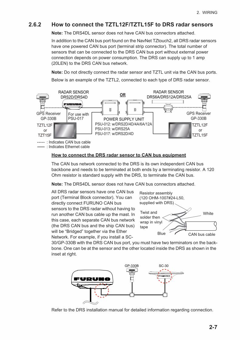
2.6.2 How to connect the TZTL12F/TZTL15F to DRS radar sensorsNote: The DRS4DL sensor does not have CAN bus connectors attached.
In addition to the CAN bus port found on the NavNet TZtouch2, all DRS radar sensors have one powered CAN bus port (terminal strip connector). The total number of sensors that can be connected to the DRS CAN bus port without external power connection depends on power consumption. The DRS can supply up to 1 amp (20LEN) to the DRS CAN bus network.
Note: Do not directly connect the radar sensor and TZTL unit via the CAN bus ports.
Below is an example of the TZTL2, connected to each type of DRS radar sensor.
How to connect the DRS radar sensor to CAN bus equipment
The CAN bus network connected to the DRS is its own independent CAN bus backbone and needs to be terminated at both ends by a terminating resistor. A 120 Ohm resistor is standard supply with the DRS, to terminate the CAN bus.
Note: The DRS4DL sensor does not have CAN bus connectors attached.
All DRS radar sensors have one CAN bus port (Terminal Block connector). You can directly connect FURUNO CAN bus sensors to the DRS radar without having to run another CAN bus cable up the mast. In this case, each separate CAN bus network (the DRS CAN bus and the ship CAN bus) will be “Bridged” together via the Ether Network. For example, if you install a SC-30/GP-330B with the DRS CAN bus port, you must have two terminators on the back-bone. One can be at the sensor and the other located inside the DRS as shown in the inset at right.
Refer to the DRS installation manual for detailed information regarding connection.
RADAR SENSOR DRS2D/DRS4D
POWER SUPPLY UNITPSU-012: w/DRS2D/4D/4A/6A/12APSU-013: w/DRS25APSU-017: w/DRS2D/4D
: Indicates Ethernet cable: Indicates CAN bus cable
For use with PSU-017
TZTL12F or
TZT15F
OR
GPS ReceiverGP-330B
RADAR SENSOR DRS6A/DRS12A/DRS25A
TZTL12F or
TZTL15F
GPS ReceiverGP-330B
Resistor assembly (120 OHM-1007#24-L50, supplied with DRS)
Twist and solder then wrap in vinyl tape
White
Blue CAN bus cable
GP-330B SC-30
2-7

2. WIRING
2.6.3 How to connect Yamaha engine(s)When interfaced with Yamaha outboard engine(s) compatible with Command Link®, Command Link Plus® and Helm Master®, the NavNet TZtouch2 can display engine in-formation on a dedicated Yamaha engine status display.
How to connect the engine
The NavNet TZtouch2 connects to the Yamaha engine network via the Yamaha Inter-face Unit. Arrange the Yamaha Interface Unit through a local Yamaha representative.
The Yamaha Engine Hub (Yamaha supply), which connects between the engine and the Yamaha Interface Unit, is also required.
Yamaha Interface Unit
To NMEA 2000 Backbone (Micro-C cable(Male))
To Yamaha Engine Hub(Command Link cable)
Yamaha Engine Hub
2-8

2. WIRING
Connection to TZTL12F, TZTL15F
Connect the Yamaha Interface Unit to the Yamaha Engine Hub.
How to set up the engine display
Once the NavNet TZtouch2 detects the Yamaha engine network, the engine can be set up on [Settings] [Initial Setup] [YAMAHA ENGINE SETUP]. See section 3.3 for details.
2.6.4 NMEA0183 equipment data inputNote: To output NMEA0183 data, see paragraph 2.3.2.
To connect NMEA0183 equipment to NavNet TZtouch2, use the CAN bus network via the optional NMEA data converter IF-NMEA2K2 (or IF-NMEA2K1). This NMEA connection can accept a baud rate of 4800 or 38400.
Heading input to NavNet TZtouch2 allows functions such as Radar Overlay and course stabilization (North up, Course up, etc.) in the radar operating modes. The NMEA0183 heading refresh rate needs to be 100 ms in order for any radar function to work properly. NMEA0183 heading can be accepted on any CAN bus port at a baud rate up to 38400 bps. In other words, data sent (IF-NMEA) and received (NavNet TZtouch2) must use the same baud rate for each individual data port.
Note 1: When using the ARPA function, set the heading refresh rate to 100 ms.
Note 2: For more information on connecting and wiring IF-NMEA2K2 or IF-NMEA2K1, refer to their respective installation manuals.
YamahaInterface
Unit
YamahaEngine
Hub
YamahaEngine
CHECK SYSTEM! Starboard Engine
: NMEA 2000: Command Link@/Command Link Plus@/Helm Master@
2-9

2. WIRING
2.6.5 CAN bus (NMEA2000) input/output
Input PGN
PGN Description059392 ISO Acknowledgment059904 ISO Request060928 ISO Address Claim
126208NMEA-Request Group FunctionNMEA-Command Group FunctionNMEA-Acknowledge Group Function
126992 System Time126996 Product Information127237 Heading/Track Control127245 Rudder127250 Vessel Heading127251 Rate of Turn127257 Attitude127258 Magnetic Variation127488 Engine Parameters, Rapid Update127489 Engine Parameters, Dynamic127505 Fluid Level128259 Speed128267 Water Depth129025 Position, Rapid Update129026 COG & SOG, Rapid Update129029 GNSS Position Data129033 Local Time Offset129038 AIS Class A Position Report129039 AIS Class B Position Report129040 AIS Class B Extended Position Report129041 AIS Aids to Navigation (AtoN) Report129291 Set & Drift, Rapid Update129538 GNSS Control Status129540 GNSS Satellites in View129793 AIS UTC and Date Report129794 AIS Class A Static and Voyage Related Data129798 AIS SAR Aircraft Position Report129801 AIS Addressed Safety Related Message129802 AIS Safety Related Broadcast Message129808 DSC Call Information129809 AIS Class B “CS” Static Data Report, Part A129810 AIS Class B “CS” Static Data Report, Part B130306 Wind Data130310 Environmental Parameters130311 Environmental Parameters130312 Temperature130313 Humidity130314 Actual Pressure130316 Temperature, Extended Range
2-10

2. WIRING
Output PGN
The CAN bus output PGN setting (found under the [Initial Setup] menu) is global to the network. Note that only one NavNet TZtouch2 will output CAN bus data on the network at a time: the NavNet TZtouch2 which is powered ON first. If that display is turned OFF, another will take its place to output the data.
130577 Direction Data130578 Vessel Speed Component
PGN Description Remarks Output cycle (msec)059392 ISO Acknowledgment For Certification Level A/B, Refusing output requirement059904 ISO Request For Certification Level A/B, Requiring output060928 ISO Address Claim For Certification Level A/B
• Address autonomy• Receiving output requirement
126208
NMEA-Request group function
For Certification Level A/+• Address autonomy• Receiving output requirement
NMEA-Command group function
For Certification Level A/+Changing the setting of other equipment
NMEA-Acknowledge group function
For Certification Level A/+Sending the confirmation for NMEA-Request group function and NMEA-Command group function
126464
PGN List-Transmit PGN’s group function
For Certification Level A/+Receiving output requirement
PGN List-Received PGN’s group function
For Certification Level A/+Receiving output requirement
126992 System Time 1000126993 Heartbeat126996 Product Information For Certification Level A/B
Receiving output requirement127250 Vessel Heading 100127251 Rate of Turn 100127257 Attitude 1000127258 Magnetic Variation 1000128259 Speed 1000128267 Water Depth 1000129025 Position, Rapid Update 100129026 COG & SOG, Rapid
Update250
129029 GNSS Position Data 1000129033 Local Time Offset 1000129283 Cross Track Error 1000129284 Navigation Data 1000129285 Navigation-Route/WP
Information• Outputs when waypoint is set/changed (own ship’s
position is required)• Outputs when receiving ISO request
130306 Wind Data 100130310 Environmental
Parameters500
130312 Temperature 2000
PGN Description
2-11

2. WIRING
2.7 Example NavNet TZtouch2 System ConfigurationsSmall vessels (Internal GPS, Internal Fish Finder, DRS4DL)
The example below shows a typical configuration for small vessels.
Note: Matching Box MB-1100 required for some FURUNO transducers. See the INTERCONNECTION DIAGRAM at the back of this manual.
130313 Humidity Outputs when receiving the ISO request130314 Actual Pressure 2000130316 Temp., Extended Range 2000
PGN Description Remarks Output cycle (msec)
Radar SensorDRS4DL
Multi Function DisplayTZTL12F/TZTL15F
Matching BoxMB-1100
12 or 24 VDC
12 or 24 VDC
600W 1kWTransducer
2-12

2. WIRING
2-13
Mid/Large-size vessels (External GPS, Fish Finder, Radar)
This is a single station plotter/radar/fish finder installation. Refer to "SYSTEM CONFIGURATION" on page ii for more details.
GPS RECEIVERGP-330B*3
Radar SensorDRS2D/DRS4D
Radar SensorDRS6A/12A/25A
DRS6A X-Class, DRS12A X-Class,DRS25A X-Class*4Radar Sensor
DRS4DL
Power Supply UnitPSU-012/013/017
12 to 24 VDC
12 to 24 VDC 12 to 24 VDC
12 to 24 VDC
12 to 24 VDC
12 to 24 VDC
Two-way cable (MOD-ASW0001/ASW002)
*1: The HUB-101 is required when two or more pieces of network equipment are connected to the TZTL unit.
*2: Local Supply
*3: Backup
(For
PS
U-0
17)
TransducerB/CM265LH, B/CM275LH-W
HUB-101*1
OR OR
Multi Function DisplayTZTL12F/TZTL15FMulti Function DisplayTZTL12F/TZTL15FMulti Function Display
TZTL12F/TZTL15FMulti Function DisplayTZTL12F/TZTL15F
CAN bus backbone cable
CAN bus drop cable
CAN bus drop cable
USB Hub*2USB Hub*2
Remote Control Unit
MCU-002SD Card Unit
SDU-001
Remote Control Unit
MCU-002SD Card Unit
SDU-001
Optional LAN cableMOD-Z072/Z073,
2 m, 3 m, 5 m, 10 m
LAN cableMOD-Z072
Network Fish FinderDFF1-UHD
Cable Assy.FRU-2P5S-FF
*4: Power Supply Unit is not required for DRS6A X-class, DRS12A X-Class and DRS25A X-Class .

2. WIRING
2-14
This page is intentionally left blank.

3. HOW TO SET UP THE EQUIPMENT
This chapter shows you how to set up your system according to the equipment you have connected.
Touch control description
The touch control depends on the screen type. The basic operations to use during the installation setup are in the following table.
Operating by a finger Function
Tap • Select a menu item.• Select a setting option where
there are multiple options.• Select an object.• Display the pop-up menu
where available.
Drag • Scroll the menu.
Pinch Change the radar range.
Increase range Reduce range
3-1

3. HOW TO SET UP THE EQUIPMENT
How to operate the menus
The following procedure shows how to use the menu system.
1. Tap (power switch) to turn the power on.2. After the startup process completes, the last used display appears and a warning
message is displayed. After reading the message, tap [OK].
3. Tap the [Home] icon ( ) to show the home screen and display mode settings.
4. Tap [Settings] to open the [Settings] menu.5. Drag the menu to show [Initial Setup], then tap [Initial Setup].
6. Depending on the menu item selected, the following operations are available:
• ON/OFF flipswitch.
Tap to switch between [ON] and [OFF]. [ON] activates the function, [OFF] deactivates the function.
• Slidebar and keyboard icon.
Drag the slidebar to adjust the setting. Settings may also be adjusted using the software keyboard for direct input.
• Keyboard icon.
Referring to the figure on the following page, use the software keyboard to input alphabet or numeric characters.
7. Tap [Close] (Indicated as an “X”) at the top right-hand side of the screen to exit.
Home menuDisplay Mode Settings
Display Mode Settings
Display Mode Settings
Menu title Close iconBack icon
Menu itemsMenu items
Preview screenChanges made in the
menu can be previewed here
Preview screenChanges made in the
menu can be previewed here
3-2

3. HOW TO SET UP THE EQUIPMENT
How to use the software keyboard
3.1 How to Set Time Zone, Time Format and Lan-guageBefore setting up your equipment, select the time zone, language and units to use on your equipment as shown below.
1. Tap the [Home] icon to show the home screen and display mode settings.2. Tap [Settings] to show the [Settings] menu.3. Drag the menu to display the [General] menu item,
then tap [General] on the main menu to show the [General] menu.
4. Drag the menu to show the [Local Time Offset] menu item, then tap [Local Time Offset] to show the option window.
5. Tap the time difference between local time and UTC time to use local time from the list.
6. Tap the [<] at the top left of the screen to return to the [General] menu.
7. Drag the menu to show the [Time Format] menu item, then tap [Time Format] to show the option window.
8. Select how to display time, in 12 or 24 hour format. [Auto] automatically inserts AM, PM indication in 24 hour clock, when the language is English.
9. Tap the [<] at the top left of the screen to return to the [General] menu.
10. Drag the menu to display the [Language] menu item, then tap [Language] on the main menu to show the language options.
No. Description1 Cursor position is highlighted.2 Backspace/Delete. Tap to erase one character at a time.3 Enter button. Tap to complete character input and apply changes.4 Cursor keys. Tap to move the cursor left/right.5 Cancel button. Aborts character entry. No changes are applied.6 Tap to switch between alphabet and numeric keyboards (where available).
_ _ _ _ _ _ _ _ _ _ _ _ _ _ _ _ _ _
Alphabet software keyboard Numeric software keyboard
ABC
1
2
3
46
35
5
4
_ _ _ _ _ _ _ _ _ _ _ _ _ _ _ _ _ _
Local Time Offset options
Language options
3-3

3. HOW TO SET UP THE EQUIPMENT
11. Tap the appropriate language to use. The unit will display a confirmation mes-sage. Tap [OK] to restart the unit and apply the new language settings.This pro-cess takes approximately five minutes to optimize the system for the new language setting. When the process is complete, the power switch color changes to orange. Tap the power switch to start the system.
3.2 How to Set Units of Measurement1. Tap the [Home] icon to show the home screen and display mode settings.2. Tap [Settings] to show the [Settings] menu.3. Drag the main menu to display [Units], then tap [Units].4. Referring to the table below, set the units to show on the display.
Menu item Description Options[Bearing Display] Adjust the bearing display format. [Magnetic], [True][True Wind Calculation Ref-erence]
Set the reference for calculating true wind speed/angle.
[Ground], [Surface]
[Position Format] Set the display format for position (Latitude/Longitude).
[DDD°MM.mmmm’], [DDD°MM.mmm’], [DDD°MM.mm’], [DDD°MM’SS.ss”], [DDD.dddddd°],[Loran-C], [MGRS]
[Loran C Station & GRI] Available when [Position Format] is selected to [Loran-C].
Set Loran C station and GRI com-bination.
[Short/Long Change Over] Set the distance at which to change between short and long range.
[0.0] to [2.0] (NM)
[Range (Long)] Set the unit of measurement for long distances.
[Nautical Mile], [Kilometer], [Mile]
[Range (Short)] Set the unit of measurement for short distances.
[Foot], [Meter], [Yard]
[Depth] Set the unit of measurement for depth.
[Foot], [Meter], [Fathom], [Passi Braza]
[Height/Length] Set the unit of measurement for height and length.
[Foot], [Meter]
[Fish Size] Set the unit of measurement for fish sizes.
[Inch], [Centimeter]
[Temperature] Set the unit of measurement for temperature.
[Fahrenheit Degree], [Celsius De-gree]
[Boat Speed] Set the unit of measurement for boat speed.
[Knot], [Kilometer per Hour], [Mile per Hour], [Meter per Second]
[Wind Speed] Set the unit of measurement for wind speed.
[Knot], [Kilometer per Hour], [Mile per Hour], [Meter per Second]
[Atmospheric Pressure] Set the unit of measurement for atmospheric pressure.
[HectoPascal], [Millibar], [Millime-ter of Mercury], [Inch of Mercury]
[Oil Pressure] Set the unit of measurement for oil pressure.
[KiloPascal], [Bar], [Pound per Square Inch]
[Volume] Set the unit of measurement for tank volume.
[Gallon] (Gallon & Gallon/hour), [Litre] (Litre & Litre/hour)
[Reset Default Settings] Restore default unit settings. [OK], [Cancel]
3-4

3. HOW TO SET UP THE EQUIPMENT
3.3 Initial SetupThis section shows you how to set your system according to the sensors you have connected.
Note: Some units are set to metric in this section, actual setting ranges vary depending on the unit of measurement set in the [Units] menu.
1. Tap the [Home] icon to show the home screen and display mode settings.2. Tap [Settings] to show the [Settings] menu.3. Drag the main menu, then tap [Initial Setup] to show the [Initial Setup] menu.4. Referring to the tables on the following pages, set your equipment.
[Initial Setup] menu - [GPS POSITION]
Engine & Tank, Instruments Setup
Manual Fuel Management Setup
Menu item Description Options (setting range)[Longitudinal (from bow] Referring to the figure on the
right, enter the GPS antenna positioning bow-stern (Longitudinal) and port-starboard (Lateral) position from the origin.
0 (m) to 999 (m)
[Lateral (-Port)] -99 (m) to +99 (m)Port-side is negative, Starboard-side is positive.
Menu item Description Options (setting range)[Boat Length] Set the length of your boat. 0 (m) to 999 (m)[Size of Static Icon] Set the size of static (such as own ship)
icons.50 to 150
[Depth Display] Select the start point for depth measure-ment.
[Under Keel], [Under Sea Level]
[External Transducer Draft]
Set draft of external transducer. 0.0 (m) to 99.9 (m)
[Keel Draft] Set the keel draft. 0.0 (m) to 99.9 (m
Menu item Description Options (setting range)[Engine & Tank Auto-matic Setup]
See "[Initial Setup] menu - [Engine & Tank Automatic Setup]" on page 3-10.
[Engine & Tank Manual Setup]
See "[Initial Setup] menu - [Engine & Tank Automatic Setup]" on page 3-10.
[Graphic Instruments Setup]
See "[Initial Setup] menu - [GRAPHIC INSTRUMENTS SETUP]" on page 3-9.
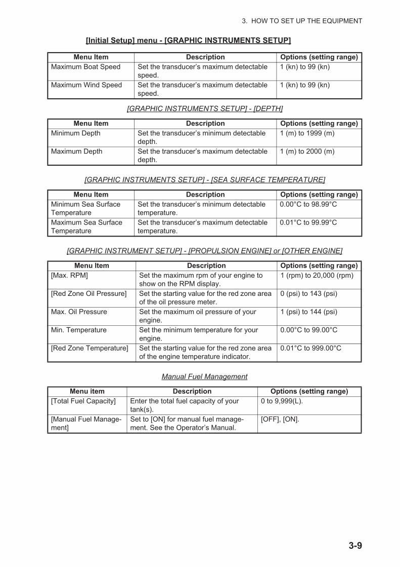
Menu item Description Options (setting range)[Total Fuel Capacity] Enter the total fuel capacity of your
tank(s).0 to 9,999(L).
[Manual Fuel Manage-ment]
Set to [ON] for manual fuel manage-ment. See the Operator’s Manual.
[OFF], [ON].
OriginOrigin
3-5

3. HOW TO SET UP THE EQUIPMENT
3-6
[Initial Setup] menu - [YAMAHA ENGINE SETUP]
[Initial Setup] menu - [IF-NMEAFI SETUP]
Menu item Description Options (setting range)[Trip & Mainte-nance]
Reset fuel used, trip distance, engine trip and maintenance hours (trip hour, standard hour, optional hour, total hour).
[Trip Fuel & Distance]: [Fuel Used], [Trip Distance].[Trip & Maintenance Hours]: [Port], [Starboard].
[Trim Level Calibra-tion]
Trim all engines to fully down position (zero). If trim level is not zero, tap [SET] to set trim level to zero.
–
[Fuel Flow Calibra-tion]
If the fuel flow indication (gph=gallons per hour) is wrong, you can calibrate the indica-tion to show correct flow. Enter a negative val-ue if the indication is higher than actual; a positive value if the indication is lower than ac-tual.
-7 to +7
[Engine Interface Software Ver. & ID]
Display engine interface software version and ID.
–
[Reset Engine Inter-face]
Reset engine interface. –
[Reset Engine In-stance]
Reset engine instance. –
[Reset Number of Engines]
Enter number of engines. [1], [2], [3], [4], [4P], [4S]
[Trouble Codes] Display trouble codes. See the operator’s manual for the Yamaha engine for details.
–
Menu item Description Options (setting range)[Select IF] Select [IF-NMEAFI] to set the analog data that is input from the IF-NMEAFI.
The setting is made after restarting the IF-NMEAFI.[Category] Select the use (category) for this sensor. [Wind], [ST800_850], [Fuel],
[FreshWater], [WasteWater], [LiveWell], [Oil], [BlackWater]
[Resistance Full] The resistance, in Ohms, when the tank is full. 0 (ohm) to 500 (Ohm)[Resistance Mid] The resistance, in Ohms, when the tank is half
full.0 (ohm) to 500 (Ohm)
[Resistance Empty] The resistance, in Ohms, when the tank is empty.
0 (ohm) to 500 (Ohm)
[Capacity] The capacity of the tank. 0 (G) to 2650 (G)[Self test] Test results are displayed.[Set Hardware to Factory Default]
Resets the converter selected at [Select IF] to factory default.
[OK], [Cancel]

3. HOW TO SET UP THE EQUIPMENT
3-7
[Initial Setup] menu - [DATA ACQUISITION]
[Initial Setup] menu - [INTERNAL GPS SETUP]
[Initial Setup] menu - [SC-30 SETUP]
This menu is only available with SC-30 connection.
[Initial Setup] menu - [CALIBRATION]
Menu Item Description Options (setting range)[GP330B WAAS Mode] Select [ON] to use the WAAS mode for the
corresponding GPS antenna.[ON], [OFF]
[WS200 WAAS Mode][Data Source] Select the source for each data to input to the system. If two or more
sources are connected for a data, select one using the pull-down dialog box. The FURUNO products are shown at the upper part of the list.
[Sensor List] Show the information for sensors connected to your equipment. Also, you can set “Nickname” for them here.
[NMEA0183 Output]
Note: If the TTM sentence is received at the same time as another sentence, the constraints to commu-nication bandwidth may cause a decrease in the number of TTM targets.
[Port Configuration] - [Baud Rate]: Select the output baud rate.
[4,800], [9,600], [38,400]
[Port Configuration] - [NMEA-0183 Ver-sion]: Select the NMEA0183 version for output.
[1.5], [2.0], [3.0]
[Sentences]: Select the sentences to out-put.
[ON], [OFF]
[NMEA2000 PGN Output] Select [ON] for the PGN's (Parameter Group Number, CAN bus (NMEA2000) message) to output from the CAN bus port.
[Sky View] Show the condition of GPS and GEO (WAAS) satellites. Number, bear-ing and elevation angle of all GPS and GEO satellites (if applicable) in view of your GPS receiver appear.
Menu Item Description Options (setting range)[WAAS Mode] Set to [OFF] when using external GPS. [ON], [OFF]
Menu item Description Options (setting range)[WAAS Mode] Select [ON] to use the WAAS mode. [ON], [OFF][Heading Offset] Enter the offset value for heading. -180° to +180°[Pitch Offset] Enter the offset value for pitching. -90° to +90°[Roll Offset] Enter the offset value for rolling. -90° to +90°
Menu item Description Options (setting range)[Heading] Offset heading data. -180.0° to +180.0°[Speed Through Water]
Calibrate speed data. Enter amount in percentage. -50% to +50%
[Wind Speed] Offset wind speed data. Enter amount in percentage. -50% to +50%[Wind Angle] Offset wind angle data. -180° to +180°[Sea Surface Temperature]
Offset sea surface temperature data. -10°C to +10 °C

3. HOW TO SET UP THE EQUIPMENT
3-8
[Initial Setup] menu - [DATA DAMPING]
[Initial Setup] menu - [FUSION]
[Initial Setup] menu - [BROWSER INSTALLATION]
[Initial Setup] menu (Other menu items)
Menu item Description Options (setting range)[COG & SOG] Set data damping time. The lower the setting
the faster the response to change.0 to 59 (seconds)
[Heading][Speed Through Water][Wind Speed & Angle][Rate of Turn]
Menu item Description Options (setting range)[Connect to Fusion] Connects to your Fusion equipment.[Fusion Auto Volume] Set to [ON] to allow the NavNet TZtouch2
unit to control the FUSION volume. Volume is adjusted according to vessel speed.
[ON], [OFF]
[Minimum Speed] Set the minimum speed threshold. Exceed-ing this speed activates volume auto control.
0.0 (kn) to 98.9 (kn)
[Maximum Speed] Set the maximum speed threshold. 0.1 (kn) to 99.0 (kn)[Volume Increase] Set the amount of extra volume to output
when the vessel reaches the [Maximum Speed] setting.
10% to 50%
Menu item Description Option (setting range)[FAX30 Browser] Show the Facsimile Receiver FAX-30 display.[FA30 Browser] Show the AIS Receiver FA-30 display.[FA50 Browser] Show the AIS Receiver FA-50 display.
Menu item Description Option (setting range)[Chart Master Device] Set to [ON] to use this unit as the master, [OFF] to use this unit as a slave.[System ID] The system ID for this device within the network.[IP Address] IP address for this unit within the network.[Quick Self Test] Displays various details regarding the TZtouch2 unit, radar and fish finder.[Certification Mark] Displays relevant certification for this equipment.[ServiceMan] Requires login password. For the service technician.[Update Network Equipments]
For the service technician.
[Event Input Configu-ration]
These menu items are not used.
[Remote Controller Configuration]
When there are multiple units in the NavNet network, the Remote Controller MCU-004 can select the display to show on the unit with MCU-004 connec-tion. Further, the cycling order of displays can be set. See the Operator’s Manual.
[Sirius Radio Diag-nostic]
Check the satellite radio of the FURUNO BBWX3 Sirius/XM Satellite Weather Receiver for proper operation. See the Operator’s Manual
[Sirius Weather Diag-nostic]
Check the weather section of the FURUNO BBWX3 Sirius/XM Satellite Weather Receiver for proper operation. See the Operator’s Manual.
[Reset Default Set-tings]
Reset the system to default settings. [OK], [Cancel]
3. HOW TO SET UP THE EQUIPMENT
3-9
[Initial Setup] menu - [GRAPHIC INSTRUMENTS SETUP]
[GRAPHIC INSTRUMENTS SETUP] - [DEPTH]
[GRAPHIC INSTRUMENTS SETUP] - [SEA SURFACE TEMPERATURE]
[GRAPHIC INSTRUMENT SETUP] - [PROPULSION ENGINE] or [OTHER ENGINE]
Manual Fuel Management
Menu Item Description Options (setting range)Maximum Boat Speed Set the transducer’s maximum detectable
speed.1 (kn) to 99 (kn)
Maximum Wind Speed Set the transducer’s maximum detectable speed.
1 (kn) to 99 (kn)
Menu Item Description Options (setting range)Minimum Depth Set the transducer’s minimum detectable
depth.1 (m) to 1999 (m)
Maximum Depth Set the transducer’s maximum detectable depth.
1 (m) to 2000 (m)
Menu Item Description Options (setting range)Minimum Sea Surface Temperature
Set the transducer’s minimum detectable temperature.
0.00°C to 98.99°C
Maximum Sea Surface Temperature
Set the transducer’s maximum detectable temperature.
0.01°C to 99.99°C
Menu Item Description Options (setting range)[Max. RPM] Set the maximum rpm of your engine to
show on the RPM display.1 (rpm) to 20,000 (rpm)
[Red Zone Oil Pressure] Set the starting value for the red zone area of the oil pressure meter.
0 (psi) to 143 (psi)
Max. Oil Pressure Set the maximum oil pressure of your engine.
1 (psi) to 144 (psi)
Min. Temperature Set the minimum temperature for your engine.
0.00°C to 99.00°C
[Red Zone Temperature] Set the starting value for the red zone area of the engine temperature indicator.
0.01°C to 999.00°C
Menu item Description Options (setting range)[Total Fuel Capacity] Enter the total fuel capacity of your
tank(s).0 to 9,999(L).
[Manual Fuel Manage-ment]
Set to [ON] for manual fuel manage-ment. See the Operator’s Manual.
[OFF], [ON].

3. HOW TO SET UP THE EQUIPMENT
3-10
CZone
[Initial Setup] menu - [Engine & Tank Automatic Setup]
The TZTL will automatically detect engines and tanks connected to the same network.
This is the recommended method for setting up engines and tanks.
[Initial Setup] menu - [Engine & Tank Manual Setup]
The manual set up method should only be used if the automatic setup did not correctly detect your engines or tanks.
Menu item Description[Add Default CZone Pages]
Create, edit C-Zone pages.
[CZone DIP Switch Settings]
Set this unit’s DIP switches. For the serviceman. Do not change the set-tings.
Menu item Description[Reset Instrument Pag-es]
Resets all instrument pages to default. [OK], [Cancel]
[Reset Default Set-tings]
Resets applicable settings to default. [OK], [Cancel]
Menu Item Description Options (setting range)[Nickname] Change the nickname for the engine or tank.[Used For Propulsion] Select which engine/tank is used to
calculate the distance which may be traveled using the remaining fuel. [ON] uses the engine/tank for calculations, [OFF] ignores the engine/tank.
[ON], [OFF]
[Reset] Resets the engine/tank details to default.
Fuel
Fuel2
Fuel3
Fuel4

3. HOW TO SET UP THE EQUIPMENT
3-11
3.4 How to Set Up the Radar1. Tap the [Home] icon to show the home screen and display mode settings.2. Tap [Radar] from the [Settings] menu.3. Tap [Radar Source], then select the appropriate radar sensor.
Note: If a DRS sensor is connected but does not appear in the [Radar Source] list, close the list and open it again. The name of the DRS sensor should appear with a check mark, as in the example below.
4. Drag the [Radar] menu display the menu item [Radar Initial Setup], then tap [Radar Initial Setup].
5. Referring to the tables on the following pages, set up the radar.
[Radar] menu - [Radar Initial Setup]
[Radar] menu - [Antenna Position]
Menu item Description Options (setting range)[Antenna Rotation] Select the speed of antenna rotation. [Auto], [24 RPM][Antenna Heading Align] See "How to align the antenna
heading" on page 3-13.[-179.9°] to [+180.0°]
[Main Bang Suppression] If main bang appears at the screen center, slide the circle icon so that the main bang disappears, while watching the radar echo at the left-hand side of the display.
[0] to [100]
[Enable Sector Blanking] Up to two sectors may be selected for blanking (no transmission). Select [ON] to enable this feature. Set the start and end angles (0° to 359°).
[ON], [OFF][Enable Sector 2 Blanking]
Menu item Description Options (setting range)[Longitudinal (from bow)] Referring to the figure on the right,
enter the radar antenna positioning bow-stern (Longitudinal) and port-starboard (Lateral) position from the origin.
[0] m to [999] m[Lateral (-Port)] [-99] m to [+99] m
Port-side is negative, Starboard-side is positive.
Menu item Description Options (setting range)[Antenna Height] Select the height of the antenna above the
waterline. Not available (greyed out) with the radar sensor DRS4DL.
[Under 3m], [3m-10m], [Over 10m]
[Auto Tuning] Enable/disable auto tuning for the connect-ed radar. Not available (greyed out) with the radar sensor DRS4D-NXT.
[ON], [OFF]
[Tuning Source] Select a display in the dual range display to manually tune. Not available (greyed out) with the radar sensor DRS4D-NXT, DRS4DL.
[Range1], [Range2]
OriginOrigin

3. HOW TO SET UP THE EQUIPMENT
3-12
[Manual Tuning] Manually tune the radar. Not available when [Auto Tuning] is enabled or the radar sensor DRS4D-NXT is used.
[-50] to [50]
[Radar Monitoring] Display various information regarding the connected radar.[Radar Optimization] Automatically adjust magnetron output and tuning for the connected
radar. Available when the [TX/STBY] setting is [ON]. Do not change these settings. Not available (greyed out) with the radar sensor DRS4D-NXT.Note 1: For the service technician only.Note 2: Do this function whenever the magnetron is replaced.
[ARPA Advanced Settings] For service technician only. Do not change these settings.This item is available when [TX/STBY] is [ON].Not available (greyed out) with the radar sensor DRS4DL, FAR-2xx7 series radar antenna.
[TX Channel] Select [1], [2] or [3], the channel where the interference is smallest. See the operator’s manual for details. Not available (greyed out) with the radar sensor DRS4D-NXT.
[Auto], [1], [2], [3]
[Target Analyzer Mode] You can emphasize rain clutter or target echoes when the target analyzer is active. Select [Rain] or [Target] as appropriate. See the operator’s manual for details. Not available (greyed out) with the radar sen-sor DRS4D-NXT.
[Rain], [Target]
[Auto acquire by Doppler] When selecting [ON], approaching targets (ships, rain clutter, etc.) within 3 NM from own ship are automatically acquired by the Doppler calculated from the radar echo. See the operator’s manual for details. Available with the radar sensor DRS4D-NXT.
[ON], [OFF]
[Set Hardware to Factory Default]
Resets the radar selected at [Radar Source] to factory default.
[OK], [Cancel]
[Reset Default Settings] Resets [Radar] menu settings to default. [OK], [Cancel]
Menu item Description Options (setting range)
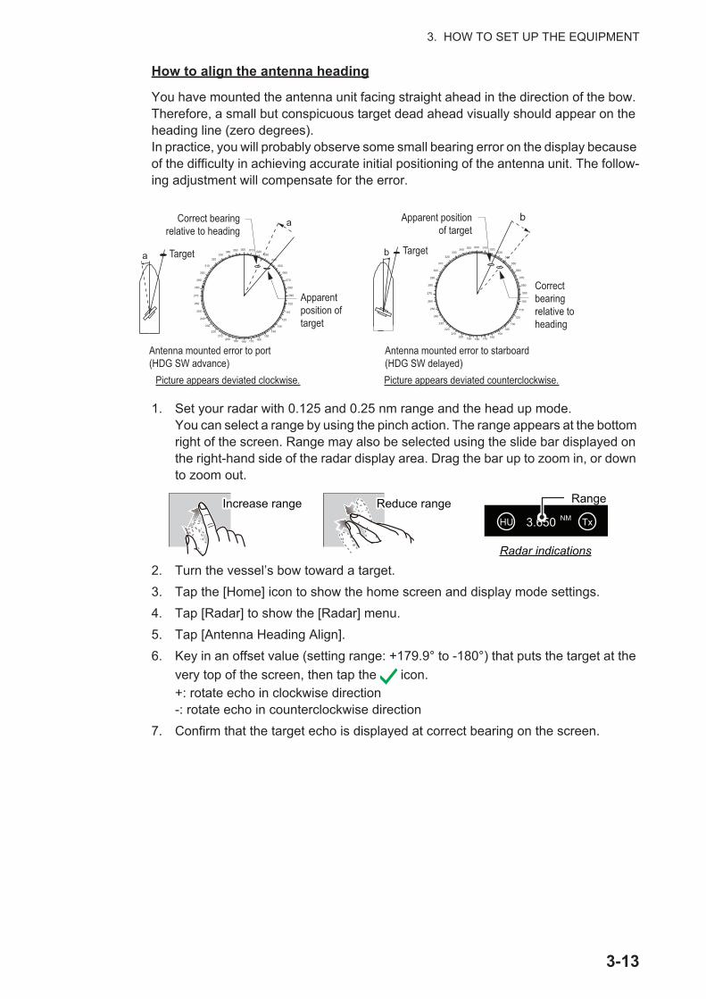
3. HOW TO SET UP THE EQUIPMENT
3-13
How to align the antenna heading
You have mounted the antenna unit facing straight ahead in the direction of the bow. Therefore, a small but conspicuous target dead ahead visually should appear on the heading line (zero degrees).In practice, you will probably observe some small bearing error on the display because of the difficulty in achieving accurate initial positioning of the antenna unit. The follow-ing adjustment will compensate for the error.
1. Set your radar with 0.125 and 0.25 nm range and the head up mode.You can select a range by using the pinch action. The range appears at the bottom right of the screen. Range may also be selected using the slide bar displayed on the right-hand side of the radar display area. Drag the bar up to zoom in, or down to zoom out.
2. Turn the vessel’s bow toward a target.3. Tap the [Home] icon to show the home screen and display mode settings.4. Tap [Radar] to show the [Radar] menu. 5. Tap [Antenna Heading Align].6. Key in an offset value (setting range: +179.9° to -180°) that puts the target at the
very top of the screen, then tap the icon.+: rotate echo in clockwise direction-: rotate echo in counterclockwise direction
7. Confirm that the target echo is displayed at correct bearing on the screen.
000 010 020030
040
050
060
070
080
090
100
110
120
130
140150
160170180190200210
220
230
240
250
260
270
280
290
300
310
320330
340 350
a Target
aCorrect bearing relative to heading
Antenna mounted error to port (HDG SW advance)
Picture appears deviated clockwise.
000 010 020030
040
050
060
070
080
090
100
110
120
130
140150
160170180190200210
220
230
240
250
260
270
280
290
300
310
320330
340 350
b Target
bApparent position of target
Antenna mounted error to starboard (HDG SW delayed)Picture appears deviated counterclockwise.
Correct bearing relative to heading
Apparent position of target
RangeIncrease rangeIncrease range Reduce rangeReduce range
Radar indications
HU NM Tx3.650

3. HOW TO SET UP THE EQUIPMENT
3-14
3.5 How to Set Up the SounderIf you have a sounder (BBDS1 or DFF series), set up the sounder as shown in this section.
Note: Some menu items are restricted to certain external depth sounders and that some menu items may not be available when using the internal depth sounder.
1. Tap the [Home] icon to show the home screen and display mode settings.2. Tap [Settings].3. Drag the [Settings] menu to display [Sounder], then tap [Sounder].4. Drag the Sounder menu to display the [SOUNDER INITIAL SETUP] menu.
Sounder Initial Setup menu
Menu item Description Options (setting range)
[Zero Line Rejec-tion]
When you turn the zero line (transmission line) rejection on, the line is not shown, which allows you to see fish echoes near the surface. The width of the line changes with the transducer used and installation characteristics. If the width of the line is 1.4 m or more, select [ON].
[ON], [OFF]
[Zero Line Range] Adjust the width of the zero line Note: DFF3 only, all other transducer models are fixed at 2.0 m
[1.4m] to [2.5m]
[Transducer Draft] Set the distance between the transducer and the draft line to show the distance from the sea surface.
[0.0m] to [99.9m]
[Salt Water] Select [ON] in you use this equipment in salt water. [ON], [OFF][Fish Finder Source]
Select the sounder used. Note: Where the TZTL12F or TZTL15F’s nickname has been changed in [INITIAL SETUP] - [SENSOR LIST], the [Fish Finder Source] option reflects the name change.
[TZTL12F] / [TZTL15F], [DFF1/BBDS1], [DFF3], [DFF1-UHD]
[Transducer Setup] Setup Transducer and Motion Sensor. See "Transducer Setup menu" on page 3-16.
[Transmission Power]
Set the TX power level.See the operator’s manual for details.Note: For DFF1-UHD users, the settings are as follows:[Off], [Min], [Auto]. The default setting is set to [Auto].
[0] to [10]
[External KP] Select on to synchronize with external sounder’s keying pulse.Note: This menu item is not available when [Fish Finder Source] is set to [TZTL].
[ON], [OFF]
[Bottom Level HF] The default bottom level setting (0) determines that two strong echoes received in sequence are bottom echoes. If the depth indication is not stable in the default setting, adjust the bottom level here. If vertical lines appear from the bottom echo in the bottom lock display, lower the bottom level to erase the vertical lines.If you can not identify the fish near the bottom from the bottom echo, increase the bottom level.
[-40] to [40][Bottom Level LF]
[Gain Offset HF] If the gain setting is wrong, or there is a difference in the gain between the low and high frequencies, you can balance the gain for the two frequencies here.
[-50] to [50][Gain Offset LF]

3. HOW TO SET UP THE EQUIPMENT
3-15
[Auto Gain Offset HF]
If the auto gain offset is wrong, or there is a difference in the gain between the low and high frequencies, set an offset here to balance auto gain for the two frequencies.
[-5] to [5]
[Auto Gain Offset LF][STC HF] Adjust the low (LF) or high (HF) STC frequency.
See the operator’s manual for details.Note: This menu item is available only for DFF3 and DFF1-UHD users.
[0] to [10][STC LF]
[Frequency Adjust HF]
Adjust the low (LF) or high (HF) frequency to remove interference caused by other fish finder’s operating on the same frequency as your fish finder.See the operator’s manual for details.Note: This menu item is available only for DFF3 users.
[-50] to [50]
[Frequency Adjust LF]
[TX Pulse HF] The pulse length is automatically set according to range and shift. Use a short pulse for better resolution and a long pulse when detection range is important. To improve res-olution on zoom displays, use [Short 1] or [Short 2]. • [Short 1] improves the detection resolution, but the de-
tection range is shorter than with [Std] (pulse length is 1/4 of [Std]).
• [Short 2] raises the detection resolution, however detec-tion range is shorter (pulse length is about 1/2 of [Std]) than [Std].
• [Std] is the standard pulse length, and is suitable for general use.
• [Long] increases the detection range but lowers the res-olution (about 1/2 compared to the [Std] pulse length)
Note: This menu item is available only for DFF3 users.
[Short1], [Short2], [Standard], [Long]
[TX Pulse LF]
[RX Band HF] Set the bandwidth for low (LF) or high (HF) frequency. The RX bandwidth is automatically set according to pulse length.To decrease noise, select [Narrow]. For better resolution, select [Wide].Note: This menu item available only for DFF3 users.
[Narrow], [Standard], [Wide]
[RX Band LF]
[Temperature Port] Set the data source for water temperature.• [MJ Port]: Use the temperature/speed sensor for data.• [Low Frequency]: Use the LF sensor for data.• [High Frequency]: Use the HF sensor for data.Note: Available only for DFF3 and DFF1-UHD users.
[MJ Port], [Low Frequency], [High Frequency]
[Sounder Demo Mode]
Enable or disable the demonstration mode for the sounder.• [OFF]: Disable the demo mode.• [Shallow]: Enable shallow water demo mode.• [Deep]: Enable deep water demo mode.Note: This menu item is not available when [Fish Finder Source] is set to [TZTL].
[OFF], [Shallow], [Deep]
[Set Hardware to Factory Default]
Reset the external fish finder to its factory default settings. [OK], [Cancel]
[Restore Default Settings]
Restore all menu settings to default. [OK], [Cancel]
Menu item Description Options (setting range)
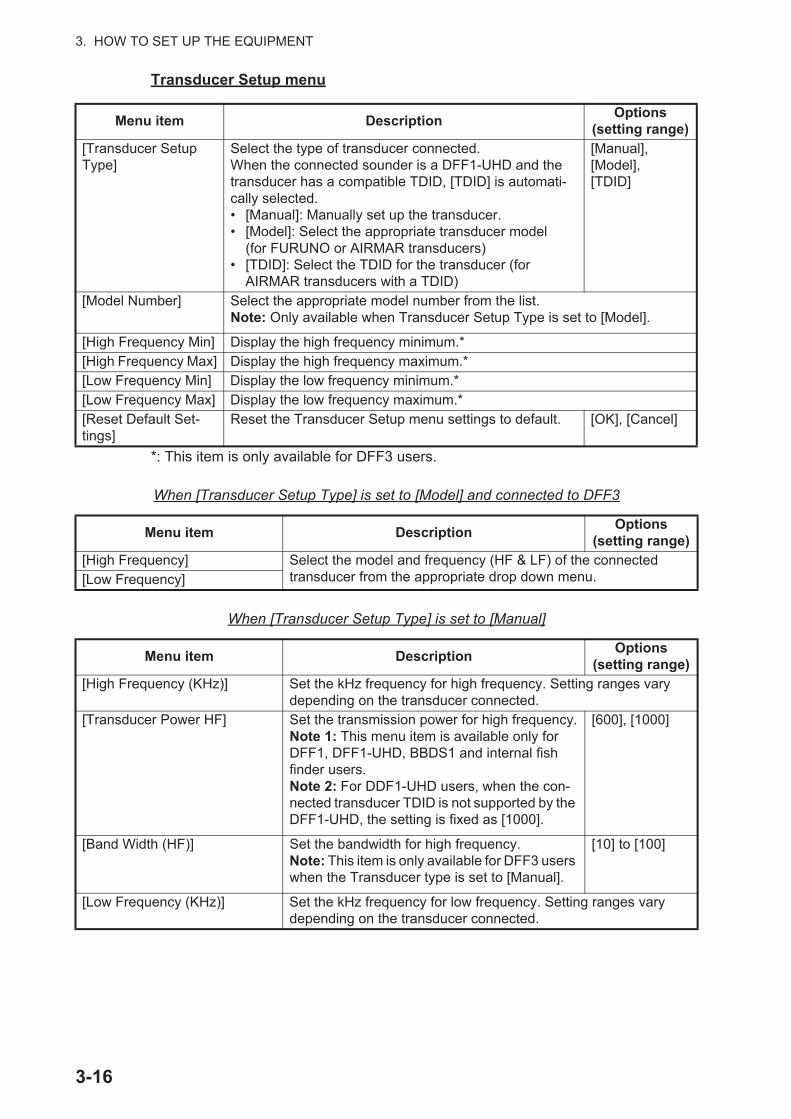
3. HOW TO SET UP THE EQUIPMENT
3-16
Transducer Setup menu
*: This item is only available for DFF3 users.
When [Transducer Setup Type] is set to [Model] and connected to DFF3
When [Transducer Setup Type] is set to [Manual]
Menu item Description Options (setting range)
[Transducer Setup Type]
Select the type of transducer connected.When the connected sounder is a DFF1-UHD and the transducer has a compatible TDID, [TDID] is automati-cally selected.• [Manual]: Manually set up the transducer.• [Model]: Select the appropriate transducer model
(for FURUNO or AIRMAR transducers)• [TDID]: Select the TDID for the transducer (for
AIRMAR transducers with a TDID)
[Manual], [Model], [TDID]
[Model Number] Select the appropriate model number from the list.Note: Only available when Transducer Setup Type is set to [Model].
[High Frequency Min] Display the high frequency minimum.*[High Frequency Max] Display the high frequency maximum.*[Low Frequency Min] Display the low frequency minimum.*[Low Frequency Max] Display the low frequency maximum.*[Reset Default Set-tings]
Reset the Transducer Setup menu settings to default. [OK], [Cancel]
Menu item Description Options (setting range)
[High Frequency] Select the model and frequency (HF & LF) of the connected transducer from the appropriate drop down menu.[Low Frequency]
Menu item Description Options (setting range)
[High Frequency (KHz)] Set the kHz frequency for high frequency. Setting ranges vary depending on the transducer connected.
[Transducer Power HF] Set the transmission power for high frequency.Note 1: This menu item is available only for DFF1, DFF1-UHD, BBDS1 and internal fish finder users.Note 2: For DDF1-UHD users, when the con-nected transducer TDID is not supported by the DFF1-UHD, the setting is fixed as [1000].
[600], [1000]
[Band Width (HF)] Set the bandwidth for high frequency.Note: This item is only available for DFF3 users when the Transducer type is set to [Manual].
[10] to [100]
[Low Frequency (KHz)] Set the kHz frequency for low frequency. Setting ranges vary depending on the transducer connected.

3. HOW TO SET UP THE EQUIPMENT
3-17
When [Transducer Setup Type] is set to [TDID]
[Transducer Power LF] Set the transmission power for low frequency.Note 1: This menu item is available only for DFF1, DFF1-UHD, BBDS1 and internal fish finder users.Note 2: For DDF1-UHD users, when the con-nected transducer TDID is not supported by the DFF1-UHD, the setting is fixed as [1000].
[600], [1000]
[Band Width (LF)] Set the bandwidth for low frequency.Note: This item is only available for DFF3 users.
[10] to [100]
Menu item Description Options (setting range)
[High Frequency] Set the frequency (kHz) for the high frequency transducer.Note: This item is displayed when the connected transducer has an unsupported TDID.
[Transducer Power HF] Set the transmission power for high frequency.Note 1: This item is only available for DFF1, DFF1-UHD, BBDS1 and internal fish finder users.Note 2: For DDF1-UHD users, when the con-nected transducer TDID is not supported by the DFF1-UHD, the setting is fixed as [1000].
[600], [1000]
[Low Frequency] Set the frequency (kHz) for the low frequency transducer.Note: This item is displayed when the connected transducer has an unsupported TDID.
[Transducer Power LF] Set the transmission power for low frequency.Note 1: This item is only available for DFF1, DFF1-UHD, BBDS1 and internal fish finder users.Note 2: For DDF1-UHD users, when the con-nected transducer TDID is not supported by the DFF1-UHD, the setting is fixed as [1000].
[600], [1000]
Menu item Description Options (setting range)

3. HOW TO SET UP THE EQUIPMENT
3-18
Motion sensor menu
Note: Motion sensor setup is not required if [Fish Finder Source] in the [Sounder] menu is set to [Internal].
When you tap [Transducer Setup] from the [Sounder] menu, the [Motion Sensor] menu is shown beneath the [Transducer Setup] menu. If the satellite compass SC-30 or SC50/110 is connected, set the distance between the antenna unit (or sensor) of the satellite compass and transducer (high and low if connected) here.
3.6 Wireless LAN Setting
3.6.1 How to join an existing wireless networkBy connecting to an existing network, you may download software updates and weather information from the internet.
1. Tap the Home icon to show the home screen and display mode settings.2. Tap [Settings], then [General].3. Tap [Wireless LAN Settings].4. Tap [Wireless Mode].5. Tap [Connect to existing LAN], then tap the [<] icon at the top left of the
display.6. Tap [Wireless] in the [ENABLE WIRELESS] menu.7. Tap [Scan] to scan the vicinity for accessible WLAN networks. Available networks
are listed. To delete all WLAN networks, select [Forget All Available Networks].
Menu item Description Options (setting range)
[Motion Sensor Type]
Select the sensor connected to you NavNet TZtouch2 unit. [SC30], [SC50_SC110]
[Antenna Posi-tion Bow/Stern HF (LF)]
Set the distance from the antenna unit to the transducer in the bow-stern direction. If the transducer is located on the fore side, set a positive value.
[-99.9] to [+99.9]
[Antenna Posi-tion Up/Down HF (LF)]
Set the distance from the transducer to the antenna unit in the vertical direction.
[-0.00] to [+99.9]
[Antenna Port/Starboard HF (LF)]
Set the distance from the antenna unit to the transducer in the port-starboard direction. If the transducer is located on the starboard side, set a positive value.
[-99.9] to [+99.9]
SC-30/50/110
Up/DownUp/Down
Bow/Stern for HFBow/Stern for HF
Bow/Stern for LFBow/Stern for LF
Port/Starboard for HFPort/Starboard for HFPort/Starboard for LFPort/Starboard for LF
HF TransducerHF Transducer
LF TransducerLF Transducer

3. HOW TO SET UP THE EQUIPMENT
3-19
8. Tap the appropriate WLAN network to show the following display.
9. Tap [Connect], and the following display appears.
10. Use the software keyboard to enter the network key, then tap the [OK] button. To see what you have input, check [Show characters].
3.6.2 How to create a wireless LAN networkSmart devices connected to this wireless network may also connect directly to the unit, allowing use of the NavNet TZtouch2 applications.
1. Tap the Home icon ( ) to show the home screen and display mode settings.
2. Tap [Settings] then [General], in that order.3. Tap [Wireless LAN Settings].4. Tap [Wireless Mode] in the [WIRELESS MODE] menu.5. Tap [Create Local Network], then tap the [<] icon at the top left of the display.6. Tap [Name] in the [LOCAL NETWORK SETTINGS] menu.
7. Using the software keyboard, name the unit, then tap the .
8. Tap [Password] in the [LOCAL NETWORK SETTINGS] menu.
9. Using the software keyboard, set the password, then tap the .
10. Tap [Local Network] in the [ENABLE LOCAL NETWORK] menu to activate the wireless network.
11. Your smart device may now be connected to the unit, through the network.1) From the smart device, select the network set at step 7.2) Input the password set at step 9.
CANCEL
FORGET
CONNECT
ENTER WIRELESS NETWORK KEY
Show characters
CANCEL

3. HOW TO SET UP THE EQUIPMENT
3-20
This page is intentionally left blank.

APPENDIX 1 INSTALLATION OF TEMPERATURE SENSORS
The installation instructions in this chapter are copied from the manufacturer's (AIRMAR Technology Corporation) installation guide, which is included with your sensor.The model numbers mentioned within the documentation should be read as follows:T42 => T-04MSBT80 => T-04MTB
AP-1

APPENDIX 1 INSTALLATION OF TEMPERATURE SENSORS
AP-2

APPENDIX 1 INSTALLATION OF TEMPERATURE SENSORS
AP-3
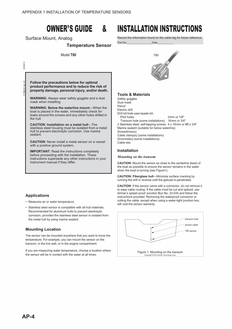
APPENDIX 1 INSTALLATION OF TEMPERATURE SENSORS
AP-4

APPENDIX 1 INSTALLATION OF TEMPERATURE SENSORS
AP-5

A-1

A-2

A-3
A-4

D-1
16/D
ec/2
016
H.M
AK
I16
/Dec
/201
6 H
.MA
KI
16/D
ec/2
016
H.M
AK
I

D-2
16/D
ec/2
016
H.M
AK
I16
/Dec
/201
6 H
.MA
KI
16/D
ec/2
016
H.M
AK
I

D-3
22/Jan/2015 H.MAKI
22/Jan/2015 H.MAKI
22/Jan/2015 H.MAKI
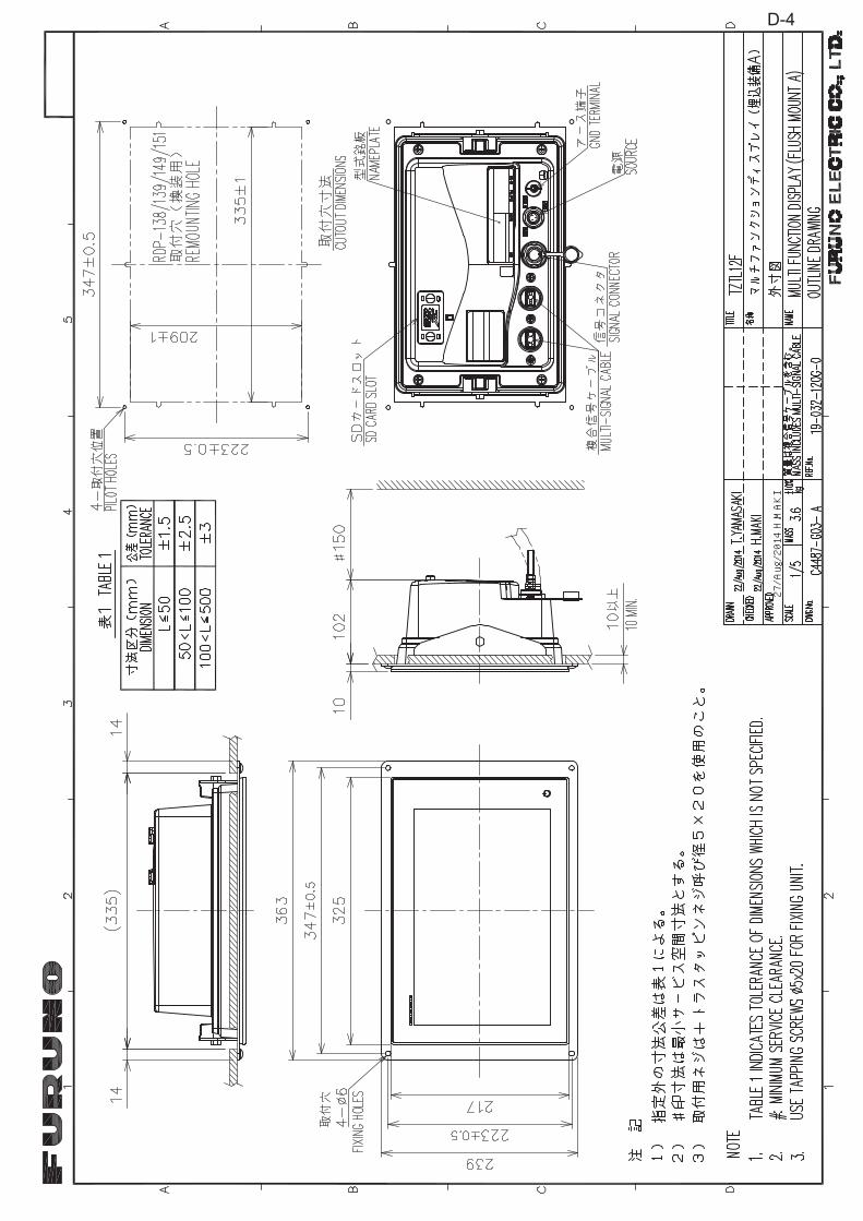
27/Aug/2014 H.MAKI
D-4

D-5
22/Jan/2015 H.MAKI
22/Jan/2015 H.MAKI
22/Jan/2015 H.MAKI

D-6
22/Jan/2015 H.MAKI
22/Jan/2015 H.MAKI
22/Jan/2015 H.MAKI

D-7
22/Jan/2015 H.MAKI
22/Jan/2015 H.MAKI
22/Jan/2015 H.MAKI

1/Sep/2014 H.MAKI
D-8

9/Ju
n/20
17 H
.MA
KI
牧 宏昌
電子署名者
: 牧
宏昌
D
N :
cn=牧
宏昌
, o=古野電気㈱
, ou
=情技課
, em
ail=
hiro
mas
a.m
aki@
furu
no.c
o.jp
, c=J
P 日付
: 20
17.0
6.09
17:
57:2
2 +0
9'00
'
S-1