installation instructions residential reverse osmosis ... ro manual.pdf · installation...
TRANSCRIPT
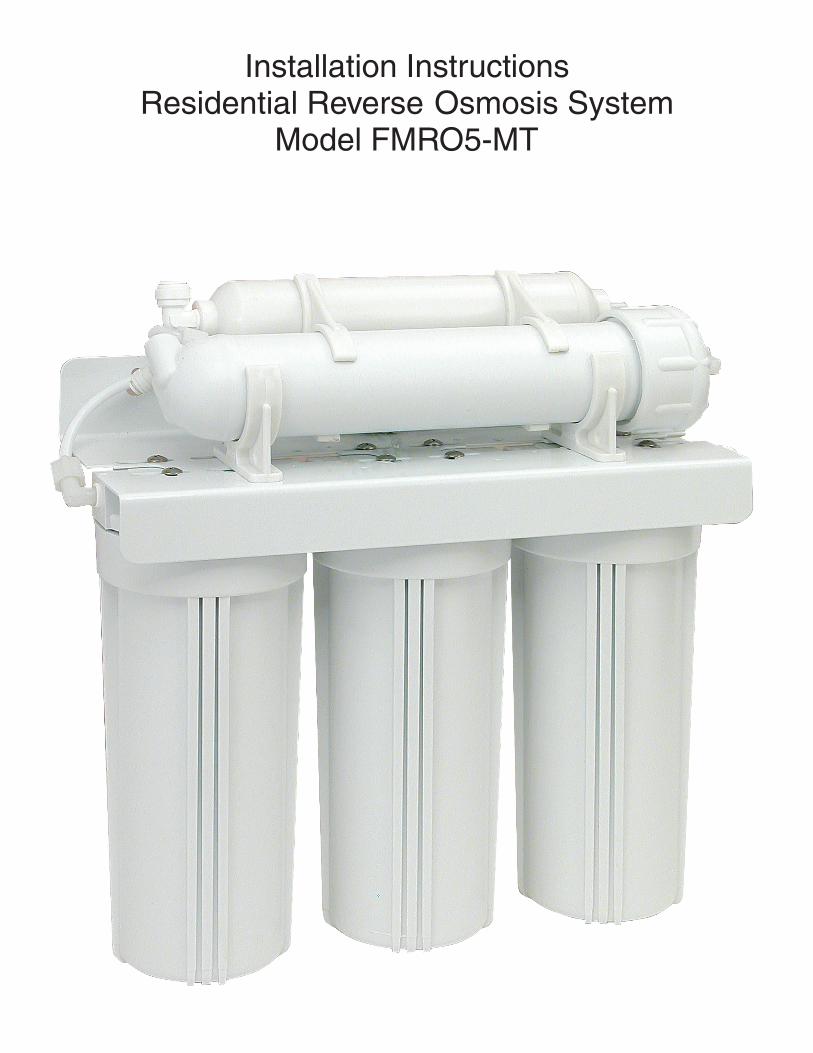
Installation InstructionsResidential Reverse Osmosis System
Model FMRO5-MT
Installation InstructionsResidential Reverse Osmosis
Drinking Water System
Your Reverse Osmosis System has been tested toensure it will operate correctly. The followingperiodic maintenance is recommended so yoursystem will provide years of trouble-free service:
Replacement parts Replacement
Pre-filter (sediment) Every 6 mos.Pre-filters (activated carbon) Every 6 mos.R/O membrane Every 2-3 yearsPost filter (carbon) Every 6 mos.
Components
The following components make up your ReverseOsmosis Drinking Water System:
Pre-filter (sediment) removes larger particles suchas sand, silt, rust and scale.
Pre-filters (activated carbon) remove chlorine in thefeed water to protect the reverse osmosismembrane.
Reverse Osmosis Membrane reduces dissolvedminerals, metals and salts. During the process,harmful compounds are separated by themembrane and the reject water goes to waste(drain).
Filter housings and R/O module hold pre-filtersand membranes. A bracket is provided so theymay be mounted, typically below sink.
Storage tank holds filtered water, ready for use.
Automatic shut-off valve senses when thestorage tank is full and closes the water supply toconserve water.
The dedicated faucet is used to dispense ROproduced water when needed.
Feed water saddle valve is connected to the coldwater line to supply water to the R/O system.
Waste water saddle valve is connected to thedrain to remove reject water from the R/O system.
Tubing supplies feed and reject water.
Fittings are used for necessary hose connections.
Tools
The following tools may be necessary, dependingon each particular installation:
Center punch and hammer
Concrete drill bitsPhillips head and flat blade screwdriversAdjustable wrenchCrescent wrenchTeflon tapePlastic tube cutterAir pressure gauge (low pressure)Air pump (hand)
System location
Your R/O system may be installed under a sink, in abasement or other location, depending on availablespace. Do not install unit where temperatures fallbelow freezing; otherwise, damage will result.Connection to an icemaker should also beconsidered for optimum performance.
Guidelines for component placement are as follows:
Faucet should be placed near the sink wheredrinking / cooking water is normally required. A 2"flat surface is required to mount the faucet if anexisting hole for a second faucet is not available.The thickness of the mounting thickness should notexceed 1-1/4".
Storage tank may be placed where it is convenient,within ten feet of the faucet. Under the sink or in anearby cabinet are excellent choices. If tank islocated further than 10 feet from the faucet, use 1/2"tubing to reduce pressure drop. Full tanks mayweight more than thirty pounds, so a sturdy shelf isrequired.
R/O unit may be mounted on either side of the sink,in a cabinet or heated basement, with nearbyaccess to a potable, cold water line.
Feed water connection is accomplished with aself-piercing feed water saddle valve. Locate thisassembly as close to the R/O unit as possible.Connect to a potable, cold water supply line only.
Note: Softened water is preferred since it willextend the life of your R/O membrane.
Drain connection is accomplished using a wastewater saddle valve which is designed to fit around astandard 1-1/2" OD drain pipe. The drain saddlevalve should always be installed above (before) thetap and on the vertical or horizontal tailpiece.
An activated carbon post-filter is provided for afinal "polish" and to remove foul tastes, odors and toprovide great tasting drinking water.
3/8" variable speed electric drill, 1/8" & 1/2" bits1-1/4" porcelain hole cutter (if hole for second faucet is not provided
1-1/4" wood bit
2Do not install the drain saddle valve near a garbagedisposal; otherwise, plugging of the waste waterline may occur. If discharging into a utility sink orstandpipe, an air gap must be provided. (Air gapsmust be 1" or greater above the floor rim.)
Note: Plumbing codes may require the use airgaps. Please check with your local municipality.
Do not connect the R/O system drain line to thedishwasher drain line due to the fact backpressures my cause the air gap to overflow.
Site preparation
Installing dealers may want to speak withcustomers in advance and ask them to clean underthe sink to save time. If a basement installation isadvisable, check area to determine if extra fittingsor hosing are required. Upon arrival, it is a goodidea to check the condition of all plumbing forpotential leaks and advise customer so there will beno misunderstandings in the event leaks occur.
Unit preparation
Open shipping carton, remove components andcheck that all parts are present. Check emptystorage tank to be sure air pressure isapproximately 7 psi. Adjust if necessary.
Installation steps
Note:
All plumbing must be completed in accordance withstate and local plumbing codes. Somemunicipalities may require installation by a licensedplumber. Check local authority prior to installation.
1. Faucet installation
If the sink has a sprayer it may be disconnected forfaucet installation. (Installing dealers shoulddiscuss this with customers.) A pipe cap or plug willbe necessary to seal the sprayer connection.
To make the faucet mounting hole (if sprayer orsecond hole is not used), check below to make surethe drill does not interfere with anything below.Center punch a small indent at the desired faucetlocation. (2" flat surface is required, not exceeding
the chassis punch and tighten nut to cut the desiredhole size. Clean up sharp edges.
The faucet should be positioned so it empties intothe sink and the spout swivels freely forconvenience. If sink has a hole that canaccommodate the RO faucet, no drilling is required.Proceed with mounting the faucet.
Porcelain, Enamel, Ceramic on Metal or Cast Iron:
Precautions must be taken to penetrate theporcelain through to the metal base and prevent itfrom chipping or scratching.
Tools required:Variable speed drillRelton porcelain cutter tool set(7/8" or alternative size, 9/16")Plumber's putty
Procedures:
2. Form shallow putty around hole area and fillwith enough water to lubricate carbide drill bit.
3. Carefully drill pilot hole through all layers. (Uselight pressure and slow speed.)
4. Insert pilot tip of spring-loaded porcelain cutterinto pilot hole.
5. Drill porcelain / enamel using spring loadedporcelain cutter, making certain a complete ringhas been cut through the porcelain / enamel tothe metal base.
6. Cut away the inner porcelain / enamel discdown to the base metal. Make certain thecutter does not touch outer rim of the cutporcelain / enamel. Continue with his bit to cutthrough metal until sink has been completelypenetrated.
Note: Always use sharpened porcelain cutter toeliminate chips and cracks.
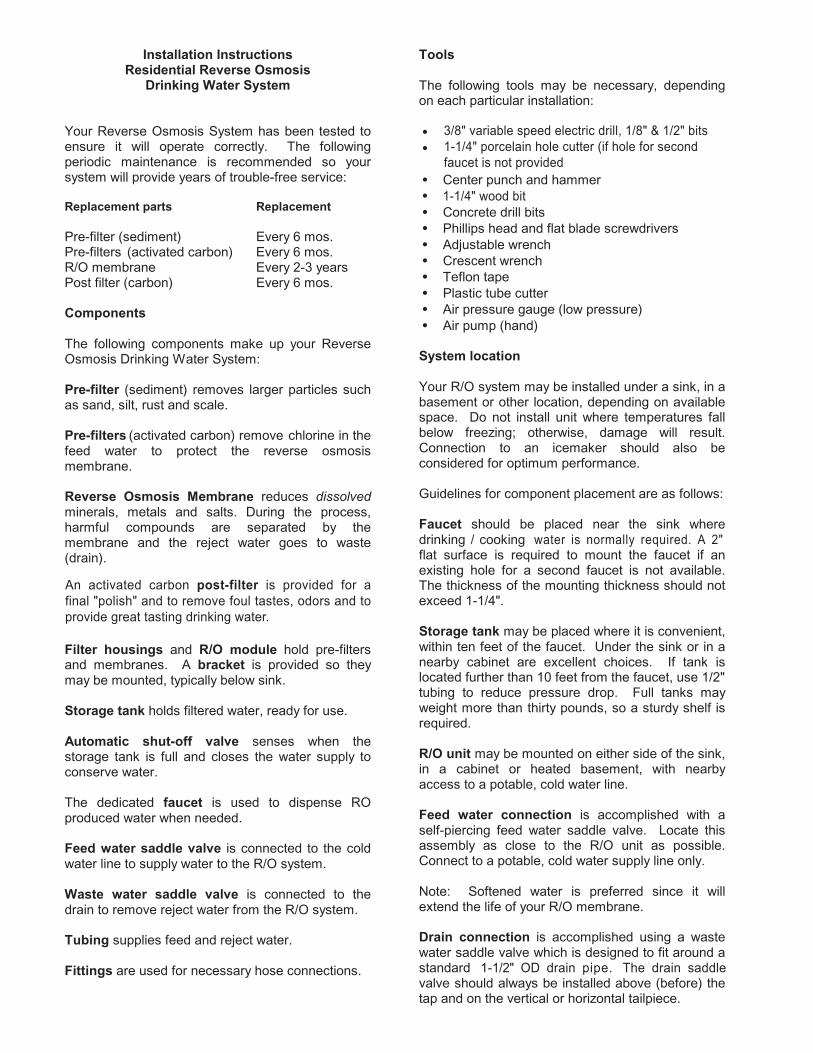
Faucet installation without air gap
Installation procedures for stainless steel sinks
Recommended tools:Center punchVariable speed drillHigh speed drill bitsGreenlee chassis punch 7/8" (or 9/16" fornon air gap faucets)Protective gloves & eye protectors
Chrome base plate
Rubber washer
Threaded nipple
Flat washer
Star washer
Hex nut
Faucet adapter
1. Mark the center for the 7/8" hole.
1-1/4" in thickness.) Drill the required pilot hole of
3Procedures:A. Center punch small indent for hole.B. Drill the required pilot hole.C. Set-up the chassis punch per instructions and
tighten nut to cut the desired hole size.D. Clean up sharp edges with file.
2. Mounting the faucet
Disassemble hardware from the threaded nipple,except for chrome base plates and rubber washers.(Rubber washers may be replaced with bead ofplumber's putty for neater appearance.)
Feed the threaded nipple through sink or countermounting hole and orient the faucet. From belowsink or counter, assemble the white spacer flatwasher and hex nut on threaded nipple and tightenby hand. (Open end up; open side toward air gap).After checking faucet orientation, tighten with awrench until secure.
3. Feed water valve and tubing installation
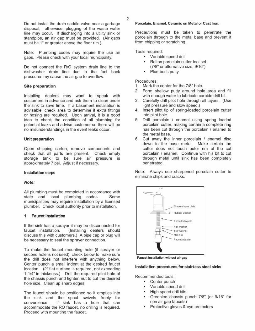
The saddle tapping valve which is supplied isdesigned for use with 3/8" to 1/2" OD soft coppersupply tubing (plain or chromed) and rigid metalpipe. Do not use with flexible ribbed supply tubingwhich is too thin and requires special hardware.
Self-tapping feed water saddle valve installation
Installation procedures using soft copper tubing:
1. Turn off cold water valve from under sink ormain water line valve for whole house.
2. Before installing saddle tapping valve, makesure piercing lance does not protrude beyondrubber gasket.
3. Assemble saddle valve on copper tubing.4. Turn handle clockwise to pierce soft copper
tube until valve is firmly seated. (Valve isclosed in this position.)
5. Turn on water supply to pressure cold waterline.
6. Snug nut/seal with wrench around valve stem.
7. Connect tubing to feed water valve using brasscompression nut, insert and plastic sleeve.
Saddle valve installations with metal pipe:
1. Turn off cold water supply.2. Drill 3/16" hole at desired location.3. At this point, make sure piercing lance does not
protrude beyond rubber gasket.4. Assemble saddle on to pipe, aligning with hole.5. Turn saddle valve handle clockwise to close
valve.6. Tighten nut/seal around valve stem with
wrench.7. Connect tubing to feed water valve using brass
compression nut, insert and plastic sleeve.8. Turn on cold water supply.9. To open valve, turn handle counterclockwise
and check for leaks.
4. Drain saddle valve installation
Prior to proceeding it is important to inspect thecondition of drain pipes to make sure they are notthin and frail.
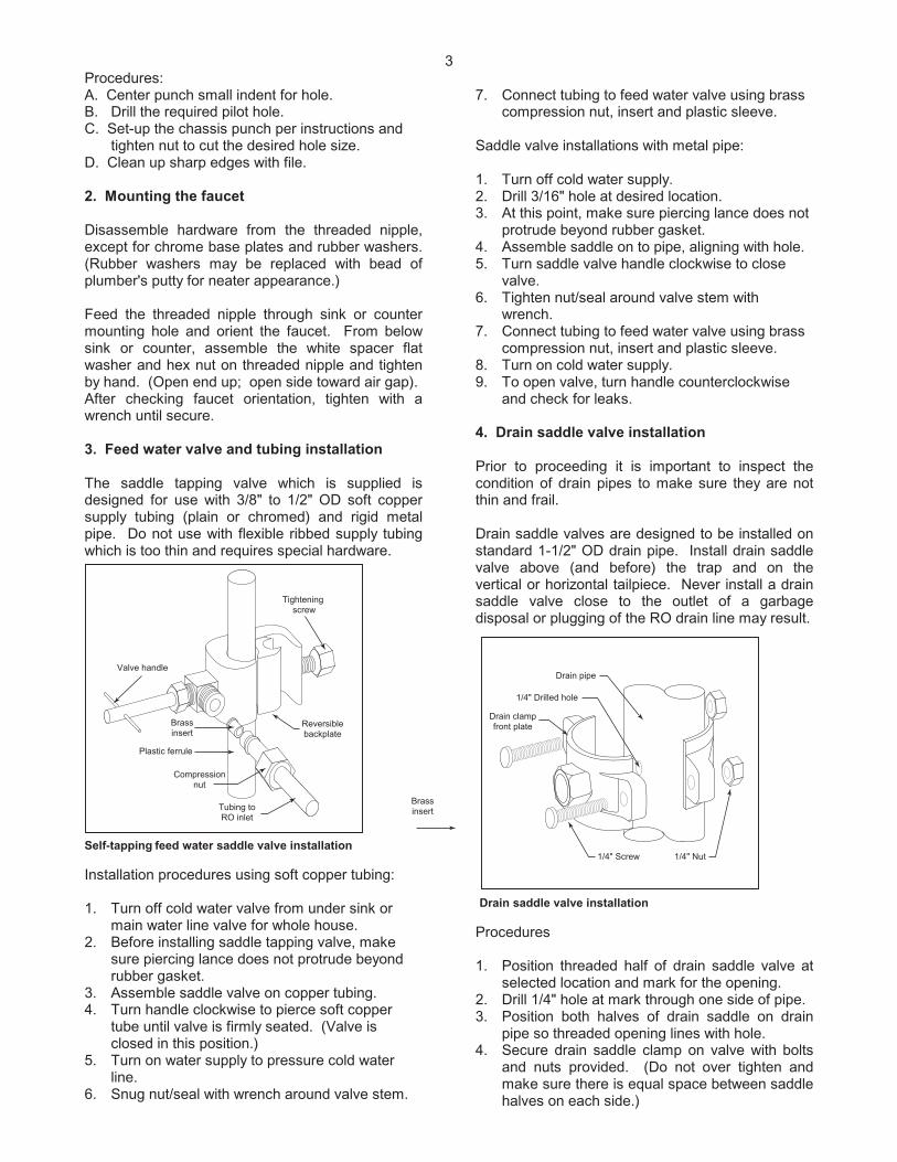
Drain saddle valves are designed to be installed onstandard 1-1/2" OD drain pipe. Install drain saddlevalve above (and before) the trap and on thevertical or horizontal tailpiece. Never install a drainsaddle valve close to the outlet of a garbagedisposal or plugging of the RO drain line may result.
Drain saddle valve installation
Procedures
1. Position threaded half of drain saddle valve atselected location and mark for the opening.
2. Drill 1/4" hole at mark through one side of pipe.3. Position both halves of drain saddle on drain
pipe so threaded opening lines with hole.4. Secure drain saddle clamp on valve with bolts
and nuts provided. (Do not over tighten andmake sure there is equal space between saddlehalves on each side.)
Valve handle
Reversiblebackplate
Tightening screw
Tubing toRO inlet
Compressionnut
Brassinsert
Plastic ferrule
Brassinsert
1/4" Screw 1/4" Nut
Drain pipe
1/4" Drilled hole
Drain clampfront plate
4
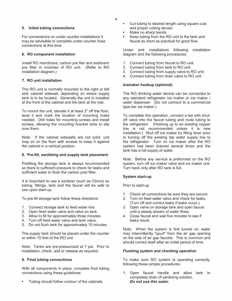
5. Initial tubing connections
For convenience on under counter installations itmay be advisable to complete under counter hoseconnections at this time.
6. RO component installation
Install RO membrane, carbon pre filer and sedimentpre filter in modules of RO unit. (Refer to ROinstallation diagram.)
7. RO unit installation
The RO unit is normally mounted to the right or leftsink cabinet sidewall, depending on where supplytank is to be located. Generally the unit is installedat the front of the cabinet and the tank at the rear.
To mount the unit, elevate it at least 2" off the floor,level it and mark the location of mounting holesneeded. Drill holes for mounting screws and installscrews, allowing the mounting bracket slots to slipover them.
Note: If the cabinet sidewalls are not solid, unitmay sit on the floor with screws to keep it againstthe cabinet in a vertical position.
8. Pre-fill, sanitizing and supply tank placement
Prefilling the storage tank is always recommendedso there is sufficient pressure to check for leaks andsufficient water to flush the carbon post filter.
It is important to use a sanitizer (such as Clorox) sotubing, fittings, tank and the faucet will be safe touse upon start-up.
To pre-fill storage tank follow these directions:
1. Connect storage tank to feed water line.2. Open feed water valve and valve on tank.3. Allow to fill for approximately three minutes.4. Turn off feed water valve and tank valve.5. Do not flush tank for approximately 15 minutes.
The supply tank should be placed under the counteror within 10 feet of the RO unit.
Note: Tanks are pre-pressurized at 7 psi. Prior toinstallation, check, add or release as required.
9. Final tubing connections
With all components in place, complete final tubingconnections using these guidelines:
Tubing should follow contour of the cabinets.
Cut tubing to desired length using square cutsand proper cutting devise.Make no sharp bends.Keep tubing from the RO unit to the tank andfaucet as short as practical for good flow.
Under sink installations following installationdiagram and the following procedures:
1. Connect tubing from faucet to RO unit.2. Connect tubing from tank to RO unit.3. Connect tubing from supply valve to RO unit.4. Connect tubing from drain valve to RO unit.
Icemaker hookup (optional)
The RO drinking water device can be connected toany standard refrigerator ice maker or ice maker /water dispenser. (Do not connect to a commercialtype bar ice maker.)
To complete this operation, connect a tee with shut-off valve into the faucet tubing and route tubing tothe refrigerator. (Hooking up to an existing copperline is not recommended unless it is newinstallation.) Shut off ice maker by lifting lever priorto turning off the existing tap water supply line tothe refrigerator. Turn on ice maker after the ROsystem has been drained several times and thetank has a full supply of water.
Note: Before any service is preformed on the ROsystem, turn off ice maker valve and ice maker unit.Turn back only after RO tank is full.
System start-up
Prior to start-up
1. Check all connections be sure they are secure.2. Turn on feed water valve and check for leaks.
(Turn off and correct leaks if leaks occur.)3. Open valve on storage tank and open faucet
until a steady stream of water flows.4. Close faucet and wait five minutes to see if
leaks result.
Note: When the system is first turned on, watermay intermittently "spurt" from the air gap openingon the side of air gap faucets. This is common andshould correct itself after an initial period of time.
Flushing system and checking operation
To make sure RO system is operating correctly,following these simple procedures:
1. Open faucet handle and allow tank tocompletely drain of sanitizing solution.Do not use this water.
5
Note: When tank is empty, faucet will steadilydrip. This is the rate the RO system processeswater.
2. With faucet handle in "open" position, measurethe rate of the steady drip from spout. Use agraduated cylinder and watch with a secondhand to calculate approximate production ingallons per day.
Note:Milliliters per minute X 0.38 = GPD.Ounces per minute X 11.2 = GPD
3. Proceed to check reject flow rate bydisconnecting tubing at drain connection andmeasure flow as described above.
Note: Proper ratio should be 3 reject water to1 part of product water, on average.
4. Close faucet and re-inspect system for leaks.
5. Allow system to process water forapproximately four hours, at which point tankwill be practically full.
6. Open faucet again and allow tank to empty for asecond time.
Do not use this water.
7. Wait another four hours to allow tank to re-fill.
Note: If no objectionable tastes are noticed aftersecond tank draining, RO processed water is readyfor use. Otherwise, drain tank and re-fill for a thirdtime.
8. At this point supply line to ice maker connection(optional) may be opened.
Maintenance
Your RO system contains filters and membraneswhich must be replaced periodically for properoperation. (Please see page 1 for general change-out recommendations.)
Note: Change-out procedures may be amended,depending on source water conditions.
To change filters and membranes follow theseprocedures:
1. Close feed water valve by turning it clockwise.2. Open faucet to allow holding tank to drain.3. Loosen and remove filter housings using
wrench provided and discard cartridges and ormembrane.
4. Wash the inside of the housings using milddetergent and soft cloth. Thoroughly rinse allsoap before reassembly.
5. Replace filter cartridges and membrane beforesanitizing system.
Note: The system should be sanitized beforeinstalling the activated carbon post filter cartridge.
Sanitizing instructions
To sanitize system follow these procedures with thefeed water valve closed:
1. Remove pre-filters and membrane fromhousings.
2. Use 5-1/4% unscented bleach such as Clorox.3. Add one cap full (2 tsp or 10 ml) of bleach to
each pre-filter housing and membrane module.4. Carefully refill housings with tap water and
temporarily replace without carbon cartridge,sediment cartridge or membrane installed.
5. Slowly open the feed water line at faucet.6. Close faucet as soon as water begins to drip
out of spout.7. Let system stand for approximately 15 minutes.8. After fifteen minutes do the following in order:
Close feed water valve.Close holding tank valve while faucet isopen to release pressure.
9. Remove housings and empty them.10. Remove any protective wrap from pre-filters
and membrane and install them in theappropriate filter housings. Tighten with wrench.
11. Replace post carbon filter if necessary.
Note:
Be sure to check o-rings are in place wheninstalling cartridges in filter housings.
12. Disconnect product water tubing from theholding tank and put 50 drops of bleach into thetubing. Reconnect tubing.
13. Slowly open feed water saddle valve. Whenwater begins to drip from faucet, close faucetand open holding tank valve.
14. Do not open faucet for at least eight (8) hours.15. Discard the first two tanks of water produced,
as they contain chlorine. Do not use thiswater.
16. When faucet is first opened, air and blackcarbon powder may be noticed. This is normal.
6
Water quality
Water quality from an RO system is normallydetermined with a TDS Meter, which measures totaldissolved solids in water, measuring conductivity.The results are normally measured in parts permillion or milligrams per liter. Fewer dissolvedsolids resul ts in higher quality water.
RO membranes are rated by the amount ofdissolved solids they reject, expressed as "rejection"percentage". For example if feed water contains100 ppm of dissolved solids and the product waterafter the membrane has 10 ppm of dissolved solidsthe rejection rate is 90%. The formula is as follows:
Percent rejection =
Feed water TDS– Product water TDS X 100%
Feed water TDS
Water production
Product water rateUsable water production from an RO system isdesignated product water rate, produced on a dailybasis. The rate is normally described in gallons perday (gpd) or milliliters per minute (ml/min.).
Reject water rateThe flow of water to drain is designated as rejectwater rate, as measured in gallons per day (gpd) ormilliliters per minute (ml/min.).
Using a graduated cylinder the formulas are:
Milliliters per minute X 0.38 = gallons per dayOunces per minute X 11.2 = gallons per day
Reject ratioThe reject ratio is the amount of water producedcompared to the amount of water flowing to drain.The formula is as follows:
Reject rateReject ratio =
Product ratePercent recoveryThe percent recovery is another way to measurethe amount of water produced compared to theamount of water which is actually used.
The formula to determined percent recovery is asfollows:
Product water rate X 100%Percent recovery =
Feed water rate
Note: Product water rate is the sum of the feedwater flow rate and reject water flow rate.
Example:
Product water rate =10 gpdReject water rate = 40 gpdFeed water = 10 gpd + 40 gpd or 50 gpd
Percent recovery = 20%
Water pressure and temperature
Product water quality and production of ROsystems is dependent on pressure andtemperature. Typically, RO membranes are treatedat standard conditions of 77˚ F (25˚ C) and 60 psi(4 bar) discharging to atmosphere. In general, thehigher the pressure differential and temperature,increased quality and quanti ty of water is produced.These factors should be considered when sizingRO systems for a particular application.
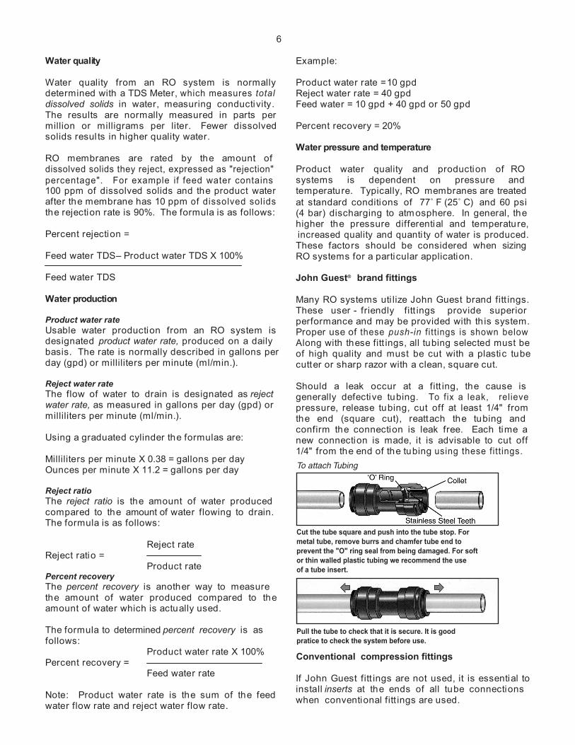
John Guest® brand fittings
Many RO systems uti lize John Guest brand fitt ings.These user - friendly fitt ings provide superiorperformance and may be provided with th is system.Proper use of these push-in fitt ings is shown belowAlong with these fitt ings, all tubing selected must beof high quality and must be cut with a plastic tubecutter or sharp razor with a clean, square cut.
Should a leak occur at a fitt ing, the cause isgenerally defective tubing. To fix a leak, relievepressure, release tubing, cut off at least 1/4" fromthe end (square cut), reattach the tubing andconfirm the connection is leak free. Each time anew connection is made, it is advisable to cut off1/4" from the end of the tubing using these fittings.
Conventional compression fittings
If John Guest fitt ings are not used, it is essential toinstall inserts at the ends of all tube connectionswhen conventional fitt ings are used.
To attach Tubing
Cut the tube square and push into the tube stop. For metal tube, remove burrs and chamfer tube end toprevent the "O" ring seal from being damaged. For soft or thin walled plastic tubing we recommend the use of a tube insert.
Pull the tube to check that it is secure. It is goodpratice to check the system before use.
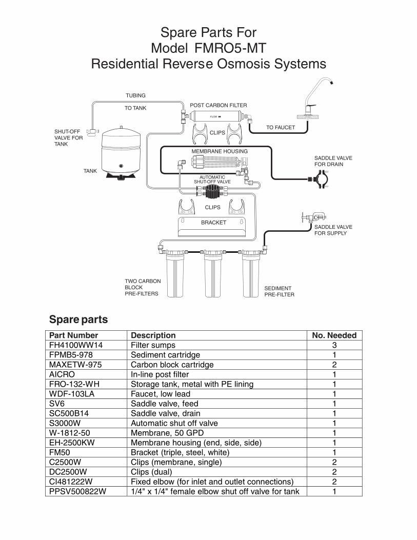
Spare Parts ForModel FMRO5 -MT
Residential Reverse Osmosis Systems
Spare partsPart Number Description No. Needed
Filter sumps 3FPMB5-978 Sediment cartridge 1MAXETW-975 Carbon block cartridge 2AICRO In-line post filter 1FRO-132-WH Storage tank, metal with PE lining 1WDF-103LA Faucet, low lead 1SV6 Saddle valve, feed 1SC500B14 Saddle valve, drain 1S3000W Automatic shut off valve 1W-1812-50 Membrane, 50 GPD 1EH-2500KW Membrane housing (end, side, side) 1FM50 Bracket (triple, steel, white) 1C2500W Clips (membrane, single) 2DC2500W Clips (dual) 2CI481222W Fixed elbow (for inlet and outlet connections) 2PPSV500822W 1/4" x 1/4" female elbow shut off valve for tank 1
TUBING
TO TANK
SHUT-OFFVALVE FORTANK
TANK
POST CARBON FILTER
TO FAUCET
MEMBRANE HOUSING
AUTOMATICSHUT-OFF VALVE
TWO CARBON BLOCKPRE-FILTERS
SEDIMENTPRE-FILTER
SADDLE VALVEFOR DRAIN
SADDLE VALVEFOR SUPPLY
FLOW
CLIPS
CLIPS
BRACKET
FH4100WW14