installation instructions - lennox · the furnace heat exchanger, components, duct system, air...
TRANSCRIPT
Page 105/11
��������506610−01
�����������
� 2011 Lennox Industries Inc.
Dallas, Texas, USA
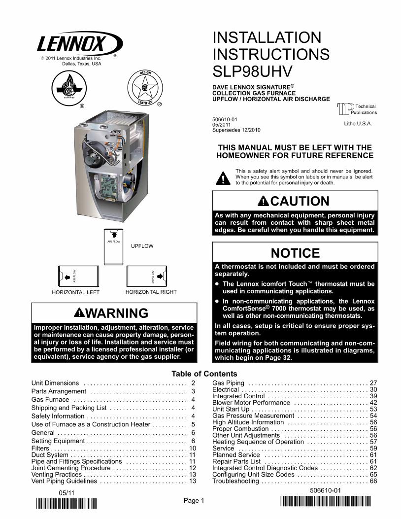
AIR FLOW
UPFLOWA
IR F
LO
W
AIR
FL
OW
HORIZONTAL RIGHTHORIZONTAL LEFT
WARNINGImproper installation, adjustment, alteration, serviceor maintenance can cause property damage, person-al injury or loss of life. Installation and service mustbe performed by a licensed professional installer (orequivalent), service agency or the gas supplier.
INSTALLATIONINSTRUCTIONSSLP98UHVDAVE LENNOX SIGNATURE®
COLLECTION GAS FURNACEUPFLOW / HORIZONTAL AIR DISCHARGE
506610−0105/2011Supersedes 12/2010
THIS MANUAL MUST BE LEFT WITH THEHOMEOWNER FOR FUTURE REFERENCE
This a safety alert symbol and should never be ignored.When you see this symbol on labels or in manuals, be alertto the potential for personal injury or death.
CAUTIONAs with any mechanical equipment, personal injurycan result from contact with sharp sheet metaledges. Be careful when you handle this equipment.
NOTICEA thermostat is not included and must be orderedseparately.
� The Lennox icomfort Touch� thermostat must beused in communicating applications.
� In non−communicating applications, the LennoxComfortSense® 7000 thermostat may be used, aswell as other non−communicating thermostats.
In all cases, setup is critical to ensure proper sys-tem operation.
Field wiring for both communicating and non−com-municating applications is illustrated in diagrams,which begin on Page 32.
Table of ContentsUnit Dimensions 2. . . . . . . . . . . . . . . . . . . . . . . . . . . . . . . .
Parts Arrangement 3. . . . . . . . . . . . . . . . . . . . . . . . . . . . . .
Gas Furnace 4. . . . . . . . . . . . . . . . . . . . . . . . . . . . . . . . . . .
Shipping and Packing List 4. . . . . . . . . . . . . . . . . . . . . . . .
Safety Information 4. . . . . . . . . . . . . . . . . . . . . . . . . . . . . . .
Use of Furnace as a Construction Heater 5. . . . . . . . . . .
General 6. . . . . . . . . . . . . . . . . . . . . . . . . . . . . . . . . . . . . . . .
Setting Equipment 6. . . . . . . . . . . . . . . . . . . . . . . . . . . . . . . Filters 10. . . . . . . . . . . . . . . . . . . . . . . . . . . . . . . . . . . . . . . . . . Duct System 11. . . . . . . . . . . . . . . . . . . . . . . . . . . . . . . . . . . . Pipe and Fittings Specifications 11. . . . . . . . . . . . . . . . . . . Joint Cementing Procedure 12. . . . . . . . . . . . . . . . . . . . . . . Venting Practices 13. . . . . . . . . . . . . . . . . . . . . . . . . . . . . . . . Vent Piping Guidelines 13. . . . . . . . . . . . . . . . . . . . . . . . . . .
Gas Piping 27. . . . . . . . . . . . . . . . . . . . . . . . . . . . . . . . . . . . . Electrical 30. . . . . . . . . . . . . . . . . . . . . . . . . . . . . . . . . . . . . . . Integrated Control 39. . . . . . . . . . . . . . . . . . . . . . . . . . . . . . . Blower Motor Performance 42. . . . . . . . . . . . . . . . . . . . . . . Unit Start Up 53. . . . . . . . . . . . . . . . . . . . . . . . . . . . . . . . . . . . Gas Pressure Measurement 54. . . . . . . . . . . . . . . . . . . . . . High Altitude Information 56. . . . . . . . . . . . . . . . . . . . . . . . . Proper Combustion 56. . . . . . . . . . . . . . . . . . . . . . . . . . . . . . Other Unit Adjustments 56. . . . . . . . . . . . . . . . . . . . . . . . . . Heating Sequence of Operation 57. . . . . . . . . . . . . . . . . . . Service 59. . . . . . . . . . . . . . . . . . . . . . . . . . . . . . . . . . . . . . . . Planned Service 61. . . . . . . . . . . . . . . . . . . . . . . . . . . . . . . . Repair Parts List 61. . . . . . . . . . . . . . . . . . . . . . . . . . . . . . . . Integrated Control Diagnostic Codes 62. . . . . . . . . . . . . . . Configuring Unit Size Codes 65. . . . . . . . . . . . . . . . . . . . . . Troubleshooting 66. . . . . . . . . . . . . . . . . . . . . . . . . . . . . . . . .
Litho U.S.A.
Page 2
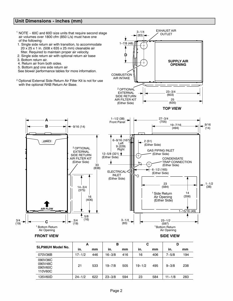
Unit Dimensions − inches (mm)
AIR FLOW
6−9/16 (167)Left
9 (229)Right
23(584)
(19)3/4
(19)1 Bottom Return
Air Opening
GAS PIPING INLET(Either Side)
Side ReturnAir Opening(Either Side)
1Bottom ReturnAir Opening
EXHAUST AIROUTLET
ELECTRICALINLET
(Either Side)
SUPPLY AIROPENING
FRONT VIEW SIDE VIEW
TOP VIEW
A
B 9/16 (14)
C3/4
27−3/4(705)
19−7/16(494)
23−1/2(597)
1−1/2(38)
6−1/2 (165)(Either Side)
33(838)
3−1/4(83)
1−15/16 (49)
14(356)
9/16(14)
12−5/8 (321)(Either Side)
2 OPTIONALEXTERNAL
SIDE RETURNAIR FILTER KIT
(Either Side)
16(406)
14−3/4(375)
2 OPTIONALEXTERNAL
SIDE RETURNAIR FILTER KIT
(Either Side)
090V48C
2 Optional External Side Return Air Filter Kit is not for usewith the optional RAB Return Air Base.
1 NOTE − 60C and 60D size units that require second stageair volumes over 1800 cfm (850 L/s) must have oneof the following:
1. Single side return air with transition, to accommodate20 x 25 x 1 in. (508 x 635 x 25 mm) cleanable airfilter. Required to maintain proper air velocity.
2. Single side return air with optional return air base3. Bottom return air.4. Return air from both sides.5. Bottom and one side return airSee blower performance tables for more information.
A B C DSLP98UH Model No.
in. mm in. mm in. mm in. mm
070V36B 17−1/2 446 16−3/8 416 16 406 7−5/8 194
090V36C
21 533 19−7/8 505 19−1/2 495 9−3/8 238090V60C110V60C
135V60D 24−1/2 622 23−3/8 594 23 584 11−1/8 283
5/8(16)
1
3−1/4(83)
23−3/4(603)
25(635)
D
1−1/2 (38)Front Panel
COMBUSTIONAIR INTAKE
2 (51)(Either Side)
1−7/8 (48)
CONDENSATETRAP CONNECTION(Either Side)
Page 3
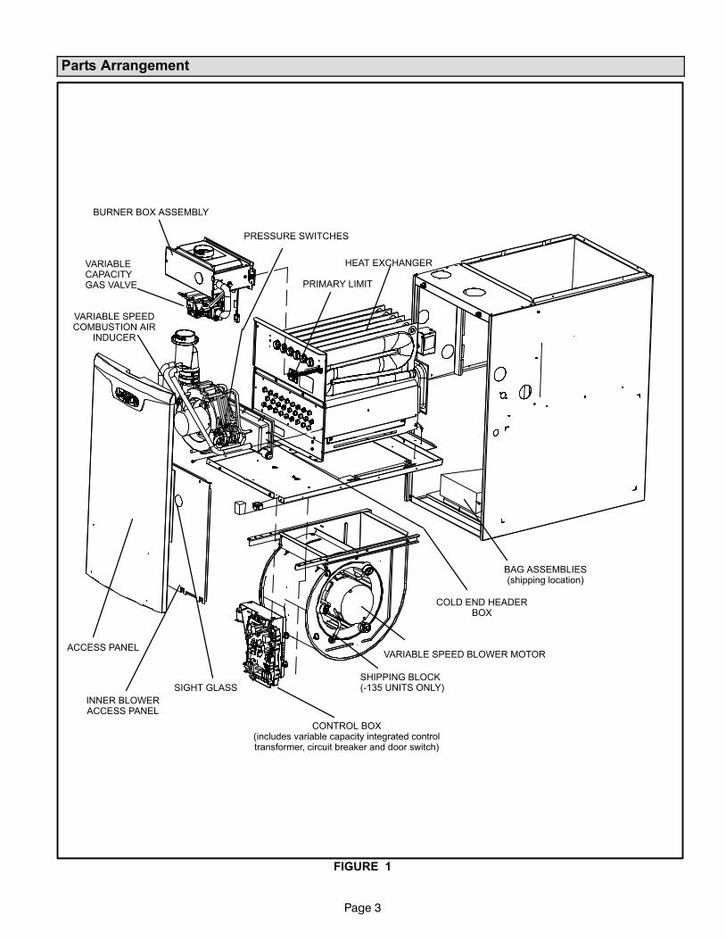
Parts Arrangement
FIGURE 1
BURNER BOX ASSEMBLY
VARIABLECAPACITYGAS VALVE
HEAT EXCHANGER
ACCESS PANEL
CONTROL BOX(includes variable capacity integrated controltransformer, circuit breaker and door switch)
VARIABLE SPEED BLOWER MOTOR
BAG ASSEMBLIES(shipping location)
COLD END HEADERBOX
PRESSURE SWITCHES
VARIABLE SPEEDCOMBUSTION AIR
INDUCER
INNER BLOWERACCESS PANEL
SIGHT GLASS
PRIMARY LIMIT
SHIPPING BLOCK(−135 UNITS ONLY)
Page 4
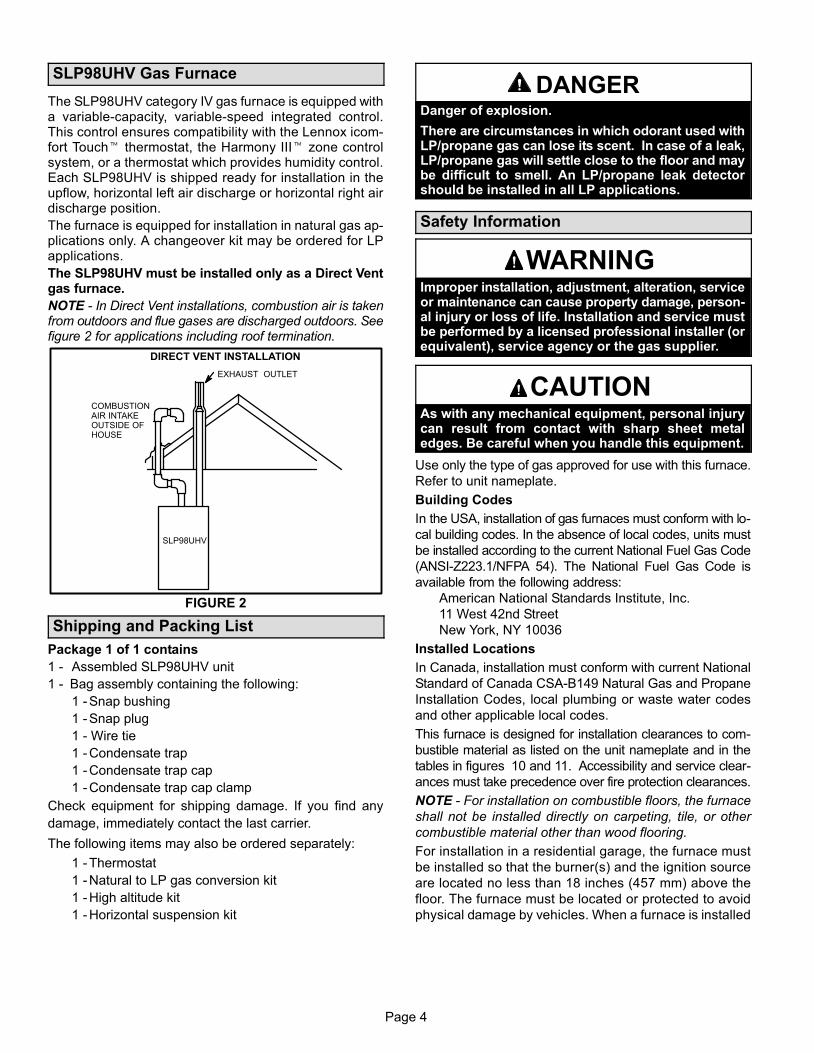
SLP98UHV Gas Furnace
The SLP98UHV category IV gas furnace is equipped witha variable−capacity, variable−speed integrated control.This control ensures compatibility with the Lennox icom-fort Touch� thermostat, the Harmony III� zone controlsystem, or a thermostat which provides humidity control.Each SLP98UHV is shipped ready for installation in theupflow, horizontal left air discharge or horizontal right airdischarge position.
The furnace is equipped for installation in natural gas ap-plications only. A changeover kit may be ordered for LPapplications.
The SLP98UHV must be installed only as a Direct Ventgas furnace.
NOTE − In Direct Vent installations, combustion air is takenfrom outdoors and flue gases are discharged outdoors. Seefigure 2 for applications including roof termination.
FIGURE 2
DIRECT VENT INSTALLATION
EXHAUST OUTLET
COMBUSTIONAIR INTAKEOUTSIDE OFHOUSE
SLP98UHV
Shipping and Packing List
Package 1 of 1 contains
1 − Assembled SLP98UHV unit
1 − Bag assembly containing the following:
1 − Snap bushing
1 − Snap plug
1 − Wire tie
1 − Condensate trap
1 − Condensate trap cap
1 − Condensate trap cap clamp
Check equipment for shipping damage. If you find any
damage, immediately contact the last carrier.
The following items may also be ordered separately:
1 − Thermostat
1 − Natural to LP gas conversion kit
1 − High altitude kit
1 − Horizontal suspension kit
DANGERDanger of explosion.
There are circumstances in which odorant used withLP/propane gas can lose its scent. In case of a leak,LP/propane gas will settle close to the floor and maybe difficult to smell. An LP/propane leak detectorshould be installed in all LP applications.
Safety Information
WARNINGImproper installation, adjustment, alteration, serviceor maintenance can cause property damage, person-al injury or loss of life. Installation and service mustbe performed by a licensed professional installer (orequivalent), service agency or the gas supplier.
CAUTIONAs with any mechanical equipment, personal injurycan result from contact with sharp sheet metaledges. Be careful when you handle this equipment.
Use only the type of gas approved for use with this furnace.
Refer to unit nameplate.
Building Codes
In the USA, installation of gas furnaces must conform with lo-
cal building codes. In the absence of local codes, units must
be installed according to the current National Fuel Gas Code
(ANSI-Z223.1/NFPA 54). The National Fuel Gas Code is
available from the following address:
American National Standards Institute, Inc.
11 West 42nd Street
New York, NY 10036
Installed Locations
In Canada, installation must conform with current National
Standard of Canada CSA-B149 Natural Gas and Propane
Installation Codes, local plumbing or waste water codes
and other applicable local codes.
This furnace is designed for installation clearances to com-
bustible material as listed on the unit nameplate and in the
tables in figures 10 and 11. Accessibility and service clear-
ances must take precedence over fire protection clearances.
NOTE − For installation on combustible floors, the furnace
shall not be installed directly on carpeting, tile, or other
combustible material other than wood flooring.
For installation in a residential garage, the furnace must
be installed so that the burner(s) and the ignition source
are located no less than 18 inches (457 mm) above the
floor. The furnace must be located or protected to avoid
physical damage by vehicles. When a furnace is installed
Page 5
in a public garage, hangar, or other building that has a haz-
ardous atmosphere, the furnace must be installed accord-
ing to recommended good practice requirements and cur-
rent National Fuel Gas Code or CSA B149 standard.
NOTE − NOTE − Furnace must be adjusted to obtain a tem-
perature rise (100% percent capacity) within the range(s)
specified on the unit nameplate. Failure to do so may cause
erratic limit operation and may also result in premature heat
exchanger failure.
This SLP98UHV furnace must be installed so that its elec-
trical components are protected from water.
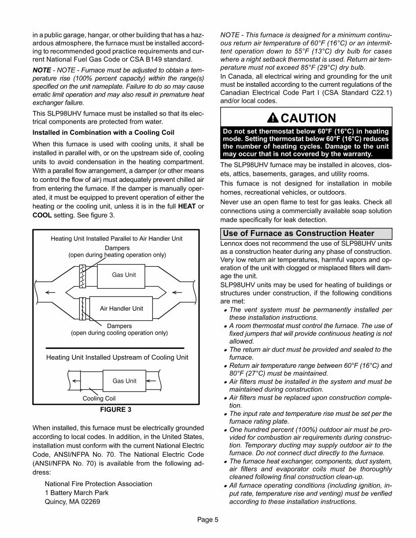
Installed in Combination with a Cooling Coil
When this furnace is used with cooling units, it shall be
installed in parallel with, or on the upstream side of, cooling
units to avoid condensation in the heating compartment.
With a parallel flow arrangement, a damper (or other means
to control the flow of air) must adequately prevent chilled air
from entering the furnace. If the damper is manually oper-
ated, it must be equipped to prevent operation of either the
heating or the cooling unit, unless it is in the full HEAT or
COOL setting. See figure 3.
FIGURE 3
Gas Unit
Heating Unit Installed Upstream of Cooling Unit
Gas Unit
Dampers(open during heating operation only)
Dampers(open during cooling operation only)
Heating Unit Installed Parallel to Air Handler Unit
Air Handler Unit
Cooling Coil
When installed, this furnace must be electrically grounded
according to local codes. In addition, in the United States,
installation must conform with the current National Electric
Code, ANSI/NFPA No. 70. The National Electric Code
(ANSI/NFPA No. 70) is available from the following ad-
dress:
National Fire Protection Association
1 Battery March Park
Quincy, MA 02269
NOTE − This furnace is designed for a minimum continu-
ous return air temperature of 60°F (16°C) or an intermit-
tent operation down to 55°F (13°C) dry bulb for cases
where a night setback thermostat is used. Return air tem-
perature must not exceed 85°F (29°C) dry bulb.
In Canada, all electrical wiring and grounding for the unit
must be installed according to the current regulations of the
Canadian Electrical Code Part I (CSA Standard C22.1)
and/or local codes.
CAUTIONDo not set thermostat below 60°F (16°C) in heatingmode. Setting thermostat below 60°F (16°C) reducesthe number of heating cycles. Damage to the unitmay occur that is not covered by the warranty.
The SLP98UHV furnace may be installed in alcoves, clos-
ets, attics, basements, garages, and utility rooms.
This furnace is not designed for installation in mobile
homes, recreational vehicles, or outdoors.
Never use an open flame to test for gas leaks. Check all
connections using a commercially available soap solution
made specifically for leak detection.
Use of Furnace as Construction Heater
Lennox does not recommend the use of SLP98UHV units
as a construction heater during any phase of construction.
Very low return air temperatures, harmful vapors and op-
eration of the unit with clogged or misplaced filters will dam-
age the unit.
SLP98UHV units may be used for heating of buildings or
structures under construction, if the following conditions
are met:
� The vent system must be permanently installed perthese installation instructions.
� A room thermostat must control the furnace. The use offixed jumpers that will provide continuous heating is notallowed.
� The return air duct must be provided and sealed to thefurnace.
� Return air temperature range between 60°F (16°C) and80°F (27°C) must be maintained.
� Air filters must be installed in the system and must bemaintained during construction.
� Air filters must be replaced upon construction comple-tion.
� The input rate and temperature rise must be set per thefurnace rating plate.
� One hundred percent (100%) outdoor air must be pro-vided for combustion air requirements during construc-tion. Temporary ducting may supply outdoor air to thefurnace. Do not connect duct directly to the furnace.
� The furnace heat exchanger, components, duct system,air filters and evaporator coils must be thoroughlycleaned following final construction clean−up.
� All furnace operating conditions (including ignition, in-
put rate, temperature rise and venting) must be verified
according to these installation instructions.

Page 6
General
WARNINGProduct contains fiberglass wool.
Disturbing the insulation in this product duringinstallation, maintenance, or repair will expose youto fiberglass wool. Breathing this may cause lungcancer. (Fiberglass wool is known to the State of Cal-ifornia to cause cancer.)
Fiberglass wool may also cause respiratory, skin,and eye irritation.
To reduce exposure to this substance or for furtherinformation, consult material safety data sheetsavailable from address shown below, or contact yoursupervisor.
Lennox Industries Inc.P.O. Box 799900Dallas, TX 75379−9900
CAUTIONSLP98UHV unit should not be installed in areas nor-mally subject to freezing temperatures.
These instructions are intended as a general guide and do
not supersede local codes in any way. Consult authorities
having jurisdiction before installation.
In addition to the requirements outlined previously, the fol-
lowing general recommendations must be considered
when installing a SLP98UHV furnace:
• Place the furnace as close to the center of the air dis-
tribution system as possible. The furnace should also be
located close to the chimney or vent termination point.
• When the furnace is installed in an attic or other insu-
lated space, keep insulation away from the furnace.
• When the furnace is installed in an unconditioned
space, consider provisions required to prevent freezing
of condensate drain system.
Installation − Setting Equipment
WARNINGDo not connect the return air ducts to the back of thefurnace. Doing so will adversely affect the operationof the safety control devices, which could result inpersonal injury or death.
FIGURE 4
Front Back
WARNINGDo not install the furnace on its front or back.See figure 4.
Upflow Applications
The SLP98UHV gas furnace can be installed as shipped
in the upflow position. Refer to figure 10 for clearances.
Select a location that allows for the required clearances
that are listed on the unit nameplate. Also consider gas
supply connections, electrical supply, vent connection,
condensate trap and drain connections, and installation
and service clearances [24 inches (610 mm) at unit
front]. The unit must be level from side to side. Unit may
be positioned from level to 1/2" toward the front to aid in
draining. See figure 5.
Page 7
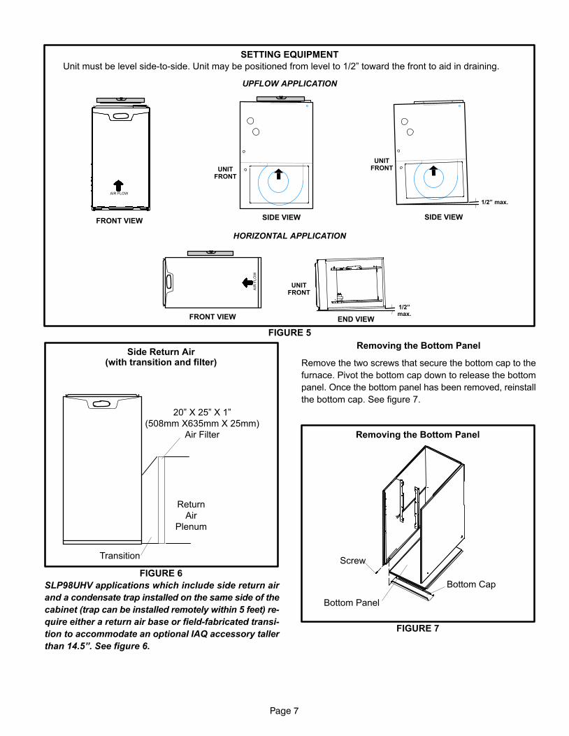
FIGURE 5
SETTING EQUIPMENT
HORIZONTAL APPLICATION
FRONT VIEW
AIR
FL
OW
END VIEW
UNITFRONT
1/2"max.
Unit must be level side−to−side. Unit may be positioned from level to 1/2" toward the front to aid in draining.
FRONT VIEWSIDE VIEW
1/2" max.
AIR FLOW
UNITFRONT
SIDE VIEW
UNITFRONT
UPFLOW APPLICATION
Side Return Air(with transition and filter)
FIGURE 6
Return
Air
Plenum
Transition
20" X 25" X 1"
(508mm X635mm X 25mm)
Air Filter
SLP98UHV applications which include side return air
and a condensate trap installed on the same side of the
cabinet (trap can be installed remotely within 5 feet) re-
quire either a return air base or field−fabricated transi-
tion to accommodate an optional IAQ accessory taller
than 14.5". See figure 6.
Removing the Bottom Panel
Remove the two screws that secure the bottom cap to the
furnace. Pivot the bottom cap down to release the bottom
panel. Once the bottom panel has been removed, reinstall
the bottom cap. See figure 7.
Removing the Bottom Panel
FIGURE 7
Screw
Bottom Panel
Bottom Cap
Page 8
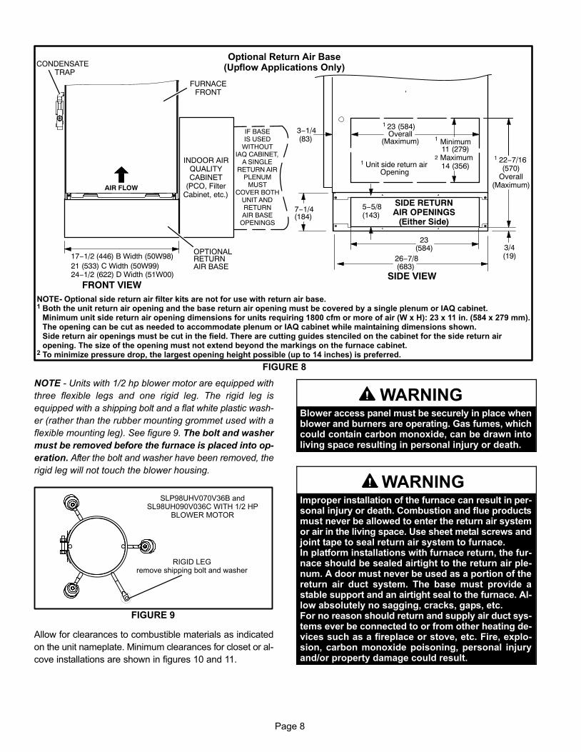
FIGURE 8
Optional Return Air Base(Upflow Applications Only)
NOTE− Optional side return air filter kits are not for use with return air base.1 Both the unit return air opening and the base return air opening must be covered by a single plenum or IAQ cabinet.
Minimum unit side return air opening dimensions for units requiring 1800 cfm or more of air (W x H): 23 x 11 in. (584 x 279 mm).The opening can be cut as needed to accommodate plenum or IAQ cabinet while maintaining dimensions shown.Side return air openings must be cut in the field. There are cutting guides stenciled on the cabinet for the side return airopening. The size of the opening must not extend beyond the markings on the furnace cabinet.
2 To minimize pressure drop, the largest opening height possible (up to 14 inches) is preferred.
FRONT VIEW
1 Unit side return airOpening
SIDE VIEW
3−1/4(83)
1 23 (584)Overall
(Maximum)
(584)23
3/4(19)
1 22−7/16(570)
Overall(Maximum)
SIDE RETURNAIR OPENINGS
(Either Side)
5−5/8(143)
1 Minimum11 (279)
2 Maximum14 (356)
(683)26−7/8
7−1/4(184)
FURNACEFRONT
AIR FLOW
IF BASEIS USED
WITHOUTIAQ CABINET,
A SINGLERETURN AIR
PLENUMMUST
COVER BOTHUNIT ANDRETURNAIR BASE
OPENINGS
INDOOR AIRQUALITYCABINET
(PCO, FilterCabinet, etc.)
AIR BASE
OPTIONALRETURN
CONDENSATETRAP
17−1/2 (446) B Width (50W98)21 (533) C Width (50W99)24−1/2 (622) D Width (51W00)
NOTE − Units with 1/2 hp blower motor are equipped with
three flexible legs and one rigid leg. The rigid leg is
equipped with a shipping bolt and a flat white plastic wash-
er (rather than the rubber mounting grommet used with a
flexible mounting leg). See figure 9. The bolt and washer
must be removed before the furnace is placed into op-
eration. After the bolt and washer have been removed, the
rigid leg will not touch the blower housing.
FIGURE 9
RIGID LEGremove shipping bolt and washer
SLP98UHV070V36B andSL98UH090V036C WITH 1/2 HP
BLOWER MOTOR
Allow for clearances to combustible materials as indicated
on the unit nameplate. Minimum clearances for closet or al-
cove installations are shown in figures 10 and 11.
WARNINGBlower access panel must be securely in place whenblower and burners are operating. Gas fumes, whichcould contain carbon monoxide, can be drawn intoliving space resulting in personal injury or death.
WARNINGImproper installation of the furnace can result in per-sonal injury or death. Combustion and flue productsmust never be allowed to enter the return air systemor air in the living space. Use sheet metal screws andjoint tape to seal return air system to furnace.In platform installations with furnace return, the fur-nace should be sealed airtight to the return air ple-num. A door must never be used as a portion of thereturn air duct system. The base must provide astable support and an airtight seal to the furnace. Al-low absolutely no sagging, cracks, gaps, etc.For no reason should return and supply air duct sys-tems ever be connected to or from other heating de-vices such as a fireplace or stove, etc. Fire, explo-sion, carbon monoxide poisoning, personal injuryand/or property damage could result.
Page 9
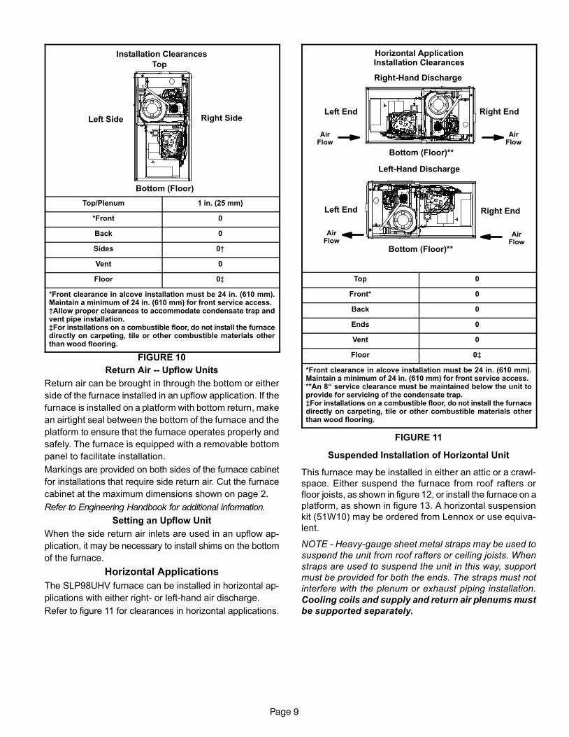
Installation Clearances
Top
Bottom (Floor)
Left Side Right Side
Top/Plenum 1 in. (25 mm)
*Front 0
Back 0
Sides 0†
Vent 0
Floor 0‡
*Front clearance in alcove installation must be 24 in. (610 mm).Maintain a minimum of 24 in. (610 mm) for front service access.†Allow proper clearances to accommodate condensate trap andvent pipe installation.‡For installations on a combustible floor, do not install the furnacedirectly on carpeting, tile or other combustible materials otherthan wood flooring.
FIGURE 10
Return Air −− Upflow Units
Return air can be brought in through the bottom or either
side of the furnace installed in an upflow application. If the
furnace is installed on a platform with bottom return, make
an airtight seal between the bottom of the furnace and the
platform to ensure that the furnace operates properly and
safely. The furnace is equipped with a removable bottom
panel to facilitate installation.
Markings are provided on both sides of the furnace cabinet
for installations that require side return air. Cut the furnace
cabinet at the maximum dimensions shown on page 2.
Refer to Engineering Handbook for additional information.
Setting an Upflow Unit
When the side return air inlets are used in an upflow ap-
plication, it may be necessary to install shims on the bottom
of the furnace.
Horizontal Applications
The SLP98UHV furnace can be installed in horizontal ap-
plications with either right− or left−hand air discharge.
Refer to figure 11 for clearances in horizontal applications.
Horizontal ApplicationInstallation Clearances
Left End Right End
Right−Hand Discharge
Left−Hand Discharge
Top
Bottom (Floor)**
Bottom (Floor)**
Left End Right End
AirFlow
AirFlow
AirFlow
AirFlow
Top 0
Front* 0
Back 0
Ends 0
Vent 0
Floor 0‡
*Front clearance in alcove installation must be 24 in. (610 mm).Maintain a minimum of 24 in. (610 mm) for front service access.**An 8� service clearance must be maintained below the unit toprovide for servicing of the condensate trap.‡For installations on a combustible floor, do not install the furnacedirectly on carpeting, tile or other combustible materials otherthan wood flooring.
FIGURE 11
Suspended Installation of Horizontal Unit
This furnace may be installed in either an attic or a crawl-
space. Either suspend the furnace from roof rafters or
floor joists, as shown in figure 12, or install the furnace on a
platform, as shown in figure 13. A horizontal suspension
kit (51W10) may be ordered from Lennox or use equiva-
lent.
NOTE − Heavy−gauge sheet metal straps may be used to
suspend the unit from roof rafters or ceiling joists. When
straps are used to suspend the unit in this way, support
must be provided for both the ends. The straps must not
interfere with the plenum or exhaust piping installation.
Cooling coils and supply and return air plenums must
be supported separately.
Page 10
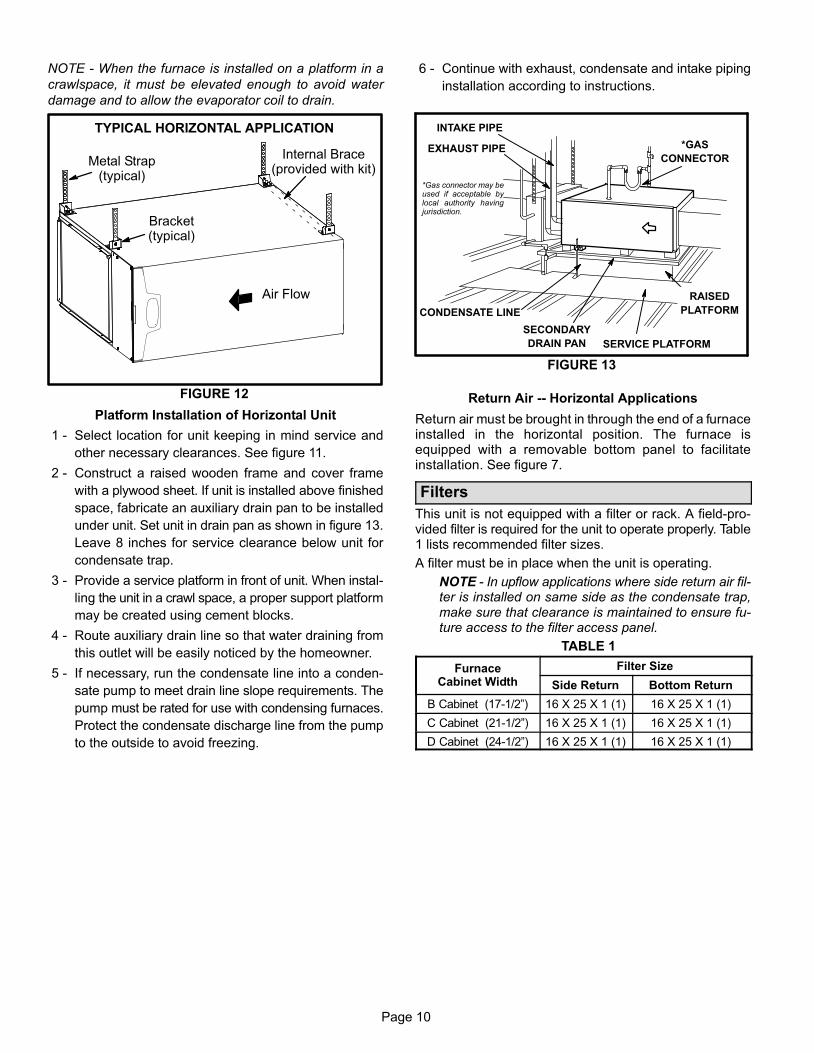
NOTE − When the furnace is installed on a platform in a
crawlspace, it must be elevated enough to avoid water
damage and to allow the evaporator coil to drain.
FIGURE 12
TYPICAL HORIZONTAL APPLICATION
Bracket(typical)
Metal Strap(typical)
Air Flow
Internal Brace(provided with kit)
Platform Installation of Horizontal Unit
1 − Select location for unit keeping in mind service and
other necessary clearances. See figure 11.
2 − Construct a raised wooden frame and cover frame
with a plywood sheet. If unit is installed above finished
space, fabricate an auxiliary drain pan to be installed
under unit. Set unit in drain pan as shown in figure 13.
Leave 8 inches for service clearance below unit for
condensate trap.
3 − Provide a service platform in front of unit. When instal-
ling the unit in a crawl space, a proper support platform
may be created using cement blocks.
4 − Route auxiliary drain line so that water draining from
this outlet will be easily noticed by the homeowner.
5 − If necessary, run the condensate line into a conden-
sate pump to meet drain line slope requirements. The
pump must be rated for use with condensing furnaces.
Protect the condensate discharge line from the pump
to the outside to avoid freezing.
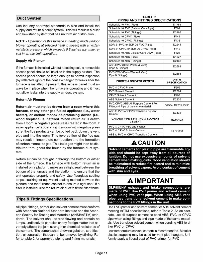
6 − Continue with exhaust, condensate and intake piping
installation according to instructions.
INTAKE PIPE
*GAS
CONNECTOR
SERVICE PLATFORM
*Gas connector may beused if acceptable bylocal authority havingjurisdiction.
EXHAUST PIPE
FIGURE 13
RAISED
PLATFORM
SECONDARY
DRAIN PAN
CONDENSATE LINE
Return Air −− Horizontal Applications
Return air must be brought in through the end of a furnaceinstalled in the horizontal position. The furnace isequipped with a removable bottom panel to facilitateinstallation. See figure 7.
Filters
This unit is not equipped with a filter or rack. A field−pro-vided filter is required for the unit to operate properly. Table1 lists recommended filter sizes.
A filter must be in place when the unit is operating.
NOTE − In upflow applications where side return air fil-ter is installed on same side as the condensate trap,make sure that clearance is maintained to ensure fu-ture access to the filter access panel.
TABLE 1
FurnaceCabinet Width
Filter Size
Side Return Bottom Return
B Cabinet (17−1/2") 16 X 25 X 1 (1) 16 X 25 X 1 (1)
C Cabinet (21−1/2") 16 X 25 X 1 (1) 16 X 25 X 1 (1)
D Cabinet (24−1/2") 16 X 25 X 1 (1) 16 X 25 X 1 (1)
Page 11
Duct System
Use industry-approved standards to size and install the
supply and return air duct system. This will result in a quiet
and low-static system that has uniform air distribution.
NOTE − Operation of this furnace in heating mode (indoor
blower operating at selected heating speed) with an exter-
nal static pressure which exceeds 0.8 inches w.c. may re-
sult in erratic limit operation.
Supply Air Plenum
If the furnace is installed without a cooling coil, a removable
access panel should be installed in the supply air duct. The
access panel should be large enough to permit inspection
(by reflected light) of the heat exchanger for leaks after the
furnace is installed. If present, this access panel must al-
ways be in place when the furnace is operating and it must
not allow leaks into the supply air duct system.
Return Air Plenum
Return air must not be drawn from a room where this
furnace, or any other gas−fueled appliance (i.e., water
heater), or carbon monoxide−producing device (i.e.,
wood fireplace) is installed. When return air is drawn
from a room, a negative pressure is created in the room. If
a gas appliance is operating in a room with negative pres-
sure, the flue products can be pulled back down the vent
pipe and into the room. This reverse flow of the flue gas
may result in incomplete combustion and the formation
of carbon monoxide gas. This toxic gas might then be dis-
tributed throughout the house by the furnace duct sys-
tem.
Return air can be brought in through the bottom or either
side of the furnace. If a furnace with bottom return air is
installed on a platform, make an airtight seal between the
bottom of the furnace and the platform to ensure that the
unit operates properly and safely. Use fiberglass sealing
strips, caulking, or equivalent sealing method between the
plenum and the furnace cabinet to ensure a tight seal. If a
filter is installed, size the return air duct to fit the filter frame.
Pipe & Fittings Specifications
All pipe, fittings, primer and solvent cement must conform
with American National Standard Institute and the Ameri-
can Society for Testing and Materials (ANSI/ASTM) stan-
dards. The solvent shall be free−flowing and contain no
lumps, undissolved particles or any foreign matter that ad-
versely affects the joint strength or chemical resistance of
the cement. The cement shall show no gelation, stratifica-
tion, or separation that cannot be removed by stirring. Re-
fer to table 2 for approved piping and fitting materials.
TABLE 2PIPING AND FITTINGS SPECIFICATIONS
Schedule 40 PVC (Pipe) D1785
Schedule 40 PVC (Cellular Core Pipe) F891
Schedule 40 PVC (Fittings) D2466
Schedule 40 CPVC (Pipe) F441
Schedule 40 CPVC (Fittings) F438
SDR−21 PVC or SDR−26 PVC (Pipe) D2241
SDR−21 CPVC or SDR−26 CPVC (Pipe) F442
Schedule 40 ABS Cellular Core DWV (Pipe) F628
Schedule 40 ABS (Pipe) D1527
Schedule 40 ABS (Fittings) D2468
ABS−DWV (Drain Waste & Vent)(Pipe & Fittings)
D2661
PVC−DWV (Drain Waste & Vent) Pipe & Fittings)
D2665
PRIMER & SOLVENT CEMENTASTM
SPECIFICATION
PVC & CPVC Primer F656
PVC Solvent Cement D2564
CPVC Solvent Cement F493
ABS Solvent Cement D2235
PVC/CPVC/ABS All Purpose Cement ForFittings & Pipe of the same material D2564, D2235, F493
ABS to PVC or CPVC Transition SolventCement D3138
CANADA PIPE & FITTING & SOLVENTCEMENT
MARKING
PVC & CPVC Pipe and Fittings
ULCS636PVC & CPVC Solvent Cement
ABS to PVC or CPVC Transition Cement
CAUTIONSolvent cements for plastic pipe are flammable liq-uids and should be kept away from all sources ofignition. Do not use excessive amounts of solventcement when making joints. Good ventilation shouldbe maintained to reduce fire hazard and to minimizebreathing of solvent vapors. Avoid contact of cementwith skin and eyes.
IMPORTANTSLP98UHV exhaust and intake connections aremade of PVC. Use PVC primer and solvent cementwhen using PVC vent pipe. When using ABS ventpipe, use transitional solvent cement to make con-nections to the PVC fittings in the unit.
Use PVC primer and solvent cement or ABS solvent cement
meeting ASTM specifications, refer to Table 2. As an alter-
nate, use all purpose cement, to bond ABS, PVC, or CPVC
pipe when using fittings and pipe made of the same materi-
als. Use transition solvent cement when bonding ABS to ei-
ther PVC or CPVC.
Low temperature solvent cement is recommended. Metal or
plastic strapping may be used for vent pipe hangers. Uni-
formly apply a liberal coat of PVC primer for PVC
Page 12
TABLE 3OUTDOOR TERMINATION KITS USAGE
SLP98UHUNIT
VENTPIPEDIA.(in.)
STANDARD CONCENTRIC
OutdoorExhaust
Accelerator(Dia. XLength)
OutdoorExhaust
Accelerator(Dia. XLength)
2" Wall PlateKit
3" Wall PlateKit
2" WallRing Kit
Flush-Mount
Kit
1−1/2"Concentric
Kit
2"Concentric
Kit
3"Concentric
Kit
1−1/2" X 12" 2" X 12"22G44
or 30G28�44J40
or 81J20�15F74 51W11**
71M80or
�44W92��
69M29or
�44W92��
60L46or 44W93�
070
2 YES YES YES* YES YES YES
2−1/2 YES YES YES* YES YES YES
3 YES YES YES* YES YES YES
090
2 YES YES YES YES YES YES
2−1/2 YES YES YES YES YES YES
3 YES YES YES YES YES YES
110
2 YES YES YES YES YES YES
2−1/2 YES YES YES YES YES
3 YES YES YES YES YES
135 3 YES YES YES YES
*Requires field−provided and installed 1−1/2" exhaust accelerator.** Kit 51W11 is provided with a 1−1/2" accelerator which must be used with all SLP98UH−070 and SLP98UH−090.
� Termination kits 44W92, 44W93, 30G28 and 81J20 are approved for use in Canadian installations.
�� The 44W92 concentric kit includes a 1−1/2" accelerator which must be installed on the exhaust outlet when this kit is used with the SLP98UH070V36B furnaces.
Canadian Applications Only − Pipe, fittings, primer
and solvent cement used to vent (exhaust) this ap-
pliance must be certified to ULC S636 and supplied by a
single manufacturer as part of an approved vent (ex-
haust) system. In addition, the first three feet of vent
pipe from the furnace flue collar must be accessible for
inspection.
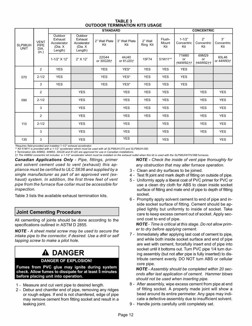
Table 3 lists the available exhaust termination kits.
Joint Cementing Procedure
All cementing of joints should be done according to thespecifications outlined in ASTM D 2855.
NOTE − A sheet metal screw may be used to secure theintake pipe to the connector, if desired. Use a drill or selftapping screw to make a pilot hole.
DANGERDANGER OF EXPLOSION!
Fumes from PVC glue may ignite during systemcheck. Allow fumes to dissipate for at least 5 minutesbefore placing unit into operation.
1 − Measure and cut vent pipe to desired length. 2 − Debur and chamfer end of pipe, removing any ridges
or rough edges. If end is not chamfered, edge of pipemay remove cement from fitting socket and result in aleaking joint.
NOTE − Check the inside of vent pipe thoroughly for
any obstruction that may alter furnace operation.
3 − Clean and dry surfaces to be joined. 4 − Test fit joint and mark depth of fitting on outside of pipe.
5 − Uniformly apply a liberal coat of PVC primer for PVC oruse a clean dry cloth for ABS to clean inside socketsurface of fitting and male end of pipe to depth of fittingsocket.
6 − Promptly apply solvent cement to end of pipe and in-
side socket surface of fitting. Cement should be ap-
plied lightly but uniformly to inside of socket. Take
care to keep excess cement out of socket. Apply sec-
ond coat to end of pipe.
NOTE − Time is critical at this stage. Do not allow prim-
er to dry before applying cement.
7 − Immediately after applying last coat of cement to pipe,
and while both inside socket surface and end of pipe
are wet with cement, forcefully insert end of pipe into
socket until it bottoms out. Turn PVC pipe 1/4 turn dur-
ing assembly (but not after pipe is fully inserted) to dis-
tribute cement evenly. DO NOT turn ABS or cellular
core pipe.
NOTE − Assembly should be completed within 20 sec-
onds after last application of cement. Hammer blows
should not be used when inserting pipe.
8 − After assembly, wipe excess cement from pipe at end
of fitting socket. A properly made joint will show a
bead around its entire perimeter. Any gaps may indi-
cate a defective assembly due to insufficient solvent.
9 − Handle joints carefully until completely set.
Page 13
Venting Practices
FIGURE 14
* See table2 for allowable pipe.
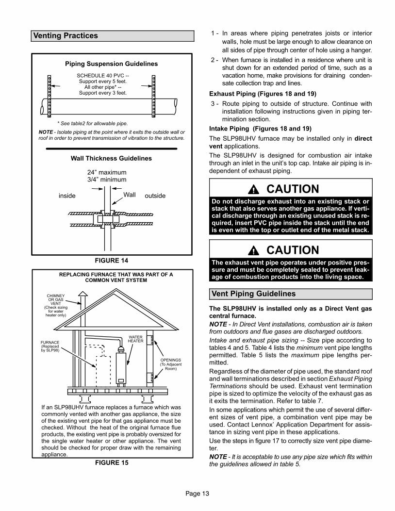
Piping Suspension Guidelines
NOTE − Isolate piping at the point where it exits the outside wall orroof in order to prevent transmission of vibration to the structure.
SCHEDULE 40 PVC −−Support every 5 feet.
All other pipe* −−Support every 3 feet.
Wallinside outside
24" maximum3/4" minimum
Wall Thickness Guidelines
If an SLP98UHV furnace replaces a furnace which wascommonly vented with another gas appliance, the sizeof the existing vent pipe for that gas appliance must bechecked. Without the heat of the original furnace flueproducts, the existing vent pipe is probably oversized forthe single water heater or other appliance. The ventshould be checked for proper draw with the remainingappliance.
FIGURE 15
REPLACING FURNACE THAT WAS PART OF ACOMMON VENT SYSTEM
CHIMNEYOR GAS
VENT(Check sizing
for waterheater only)
FURNACE(Replacedby SLP98)
WATERHEATER
OPENINGS(To Adjacent
Room)
1 − In areas where piping penetrates joists or interior
walls, hole must be large enough to allow clearance on
all sides of pipe through center of hole using a hanger.
2 − When furnace is installed in a residence where unit is
shut down for an extended period of time, such as a
vacation home, make provisions for draining conden-
sate collection trap and lines.
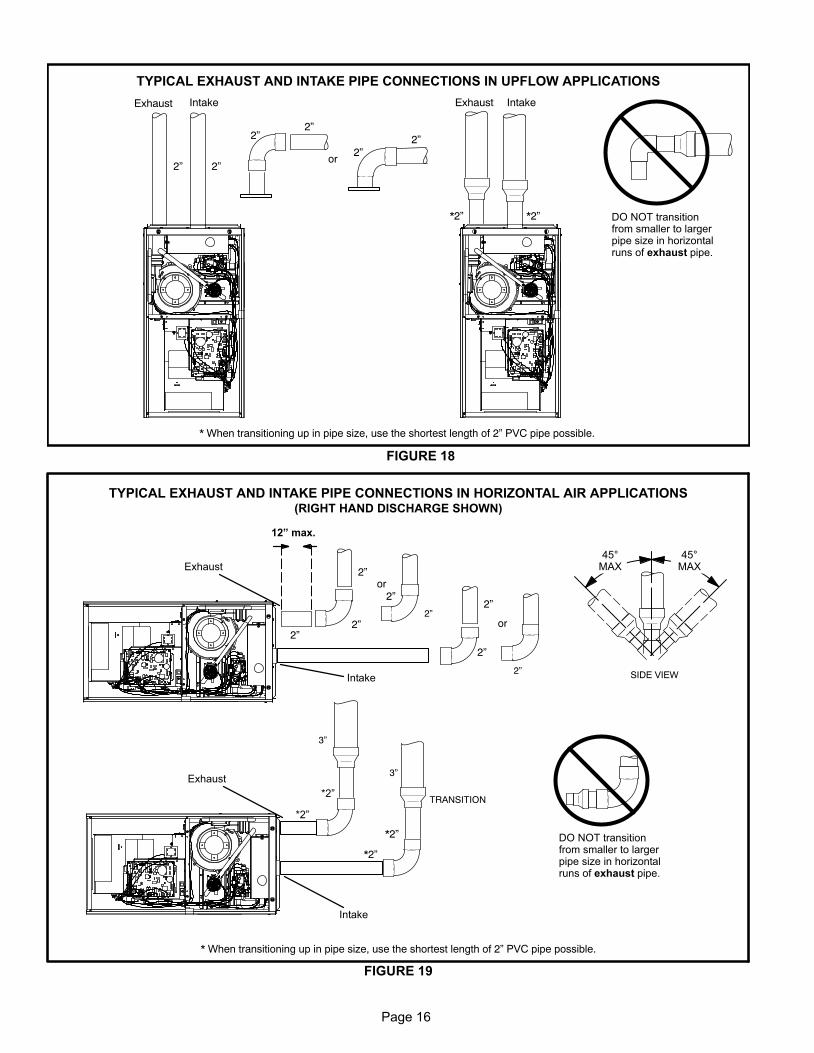
Exhaust Piping (Figures 18 and 19)
3 − Route piping to outside of structure. Continue with
installation following instructions given in piping ter-
mination section.
Intake Piping (Figures 18 and 19)
The SLP98UHV furnace may be installed only in direct
vent applications.
The SLP98UHV is designed for combustion air intake
through an inlet in the unit’s top cap. Intake air piping is in-
dependent of exhaust piping.
CAUTIONDo not discharge exhaust into an existing stack orstack that also serves another gas appliance. If verti-cal discharge through an existing unused stack is re-quired, insert PVC pipe inside the stack until the endis even with the top or outlet end of the metal stack.
CAUTIONThe exhaust vent pipe operates under positive pres-sure and must be completely sealed to prevent leak-age of combustion products into the living space.
Vent Piping Guidelines
The SLP98UHV is installed only as a Direct Vent gascentral furnace.
NOTE − In Direct Vent installations, combustion air is takenfrom outdoors and flue gases are discharged outdoors.
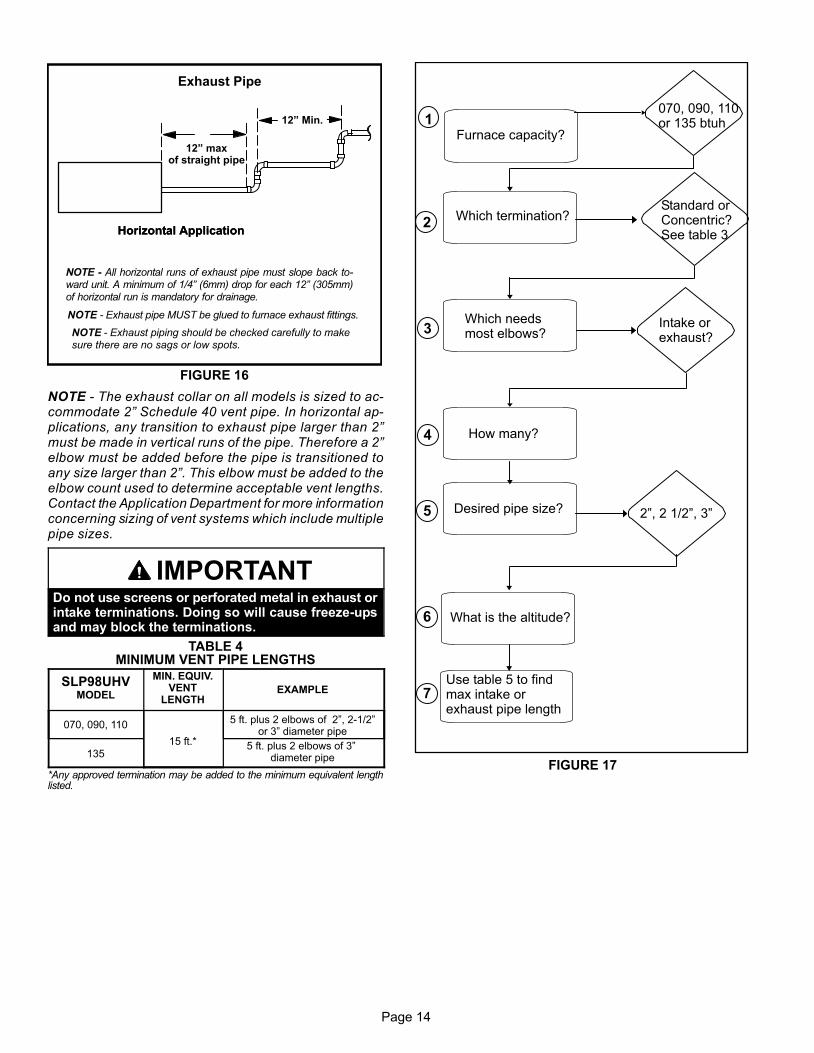
Intake and exhaust pipe sizing −− Size pipe according totables 4 and 5. Table 4 lists the minimum vent pipe lengthspermitted. Table 5 lists the maximum pipe lengths per-mitted.
Regardless of the diameter of pipe used, the standard roofand wall terminations described in section Exhaust PipingTerminations should be used. Exhaust vent terminationpipe is sized to optimize the velocity of the exhaust gas asit exits the termination. Refer to table 7.
In some applications which permit the use of several differ-ent sizes of vent pipe, a combination vent pipe may beused. Contact Lennox’ Application Department for assis-tance in sizing vent pipe in these applications.
Use the steps in figure 17 to correctly size vent pipe diame-ter.
NOTE − It is acceptable to use any pipe size which fits withinthe guidelines allowed in table 5.
Page 14
12" maxof straight pipe
FIGURE 16
Exhaust Pipe
Horizontal Application
12" Min.
NOTE − Exhaust pipe MUST be glued to furnace exhaust fittings.
NOTE − All horizontal runs of exhaust pipe must slope back to-ward unit. A minimum of 1/4" (6mm) drop for each 12" (305mm)of horizontal run is mandatory for drainage.
NOTE − Exhaust piping should be checked carefully to makesure there are no sags or low spots.
Horizontal Application
NOTE − The exhaust collar on all models is sized to ac-commodate 2" Schedule 40 vent pipe. In horizontal ap-plications, any transition to exhaust pipe larger than 2"must be made in vertical runs of the pipe. Therefore a 2"elbow must be added before the pipe is transitioned toany size larger than 2". This elbow must be added to theelbow count used to determine acceptable vent lengths.Contact the Application Department for more informationconcerning sizing of vent systems which include multiplepipe sizes.
IMPORTANTDo not use screens or perforated metal in exhaust orintake terminations. Doing so will cause freeze−upsand may block the terminations.
TABLE 4MINIMUM VENT PIPE LENGTHS
SLP98UHVMODEL
MIN. EQUIV.VENT
LENGTHEXAMPLE
070, 090, 110
15 ft.*
5 ft. plus 2 elbows of 2", 2−1/2"or 3" diameter pipe
1355 ft. plus 2 elbows of 3"
diameter pipe
*Any approved termination may be added to the minimum equivalent lengthlisted.
1
2
3
4
5
6
070, 090, 110or 135 btuh
Which termination?Standard orConcentric?See table 3
Intake orexhaust?
Which needsmost elbows?
How many?
2", 2 1/2", 3"Desired pipe size?
Use table 5 to findmax intake orexhaust pipe length
FIGURE 17
What is the altitude?
7
Furnace capacity?
Page 15
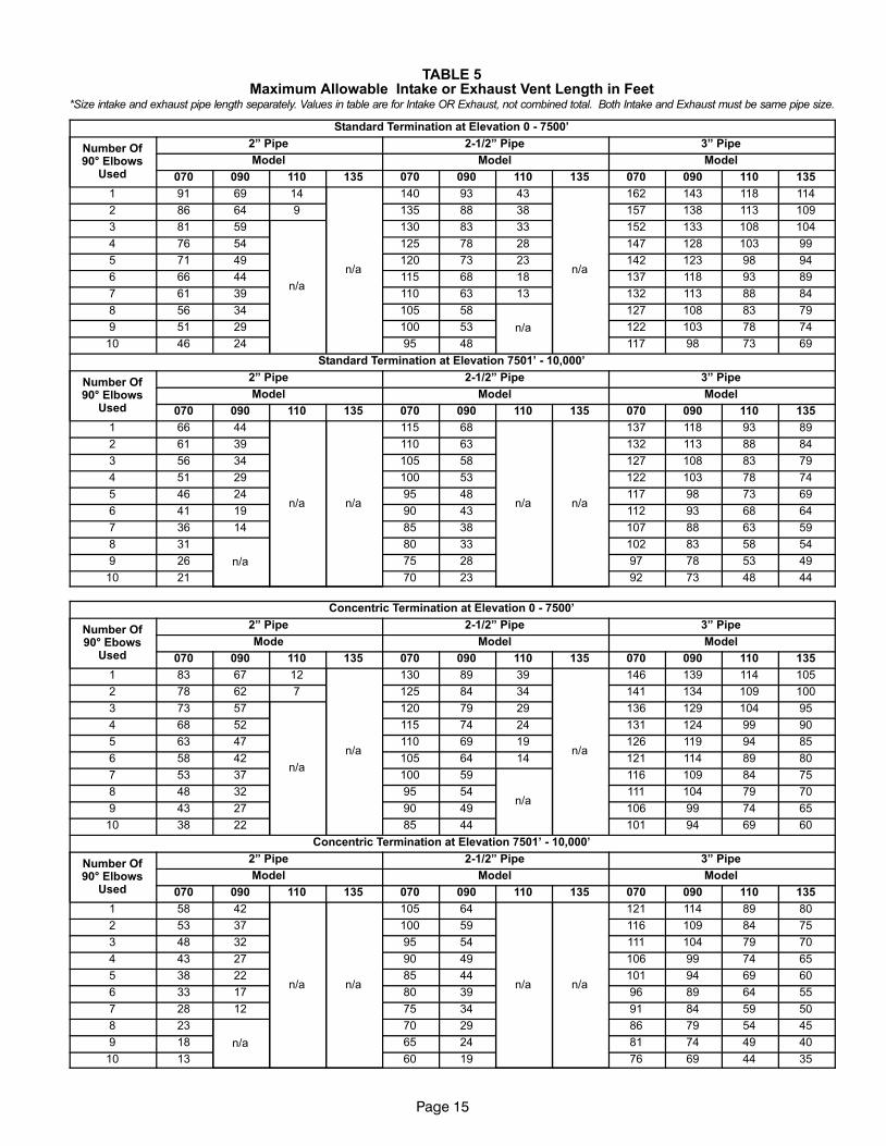
TABLE 5Maximum Allowable Intake or Exhaust Vent Length in Feet
*Size intake and exhaust pipe length separately. Values in table are for Intake OR Exhaust, not combined total. Both Intake and Exhaust must be same pipe size.
Standard Termination at Elevation 0 − 7500’
Number Of90° Elbows
Used
2" Pipe 2−1/2" Pipe 3" Pipe
Model Model Model
070 090 110 135 070 090 110 135 070 090 110 135
1 91 69 14
n/a
140 93 43
n/a
162 143 118 114
2 86 64 9 135 88 38 157 138 113 109
3 81 59
n/a
130 83 33 152 133 108 104
4 76 54 125 78 28 147 128 103 99
5 71 49 120 73 23 142 123 98 94
6 66 44 115 68 18 137 118 93 89
7 61 39 110 63 13 132 113 88 84
8 56 34 105 58
n/a
127 108 83 79
9 51 29 100 53 122 103 78 74
10 46 24 95 48 117 98 73 69
Standard Termination at Elevation 7501’ − 10,000’
Number Of90° Elbows
Used
2" Pipe 2−1/2" Pipe 3" Pipe
Model Model Model
070 090 110 135 070 090 110 135 070 090 110 135
1 66 44
n/a n/a
115 68
n/a n/a
137 118 93 89
2 61 39 110 63 132 113 88 84
3 56 34 105 58 127 108 83 79
4 51 29 100 53 122 103 78 74
5 46 24 95 48 117 98 73 69
6 41 19 90 43 112 93 68 64
7 36 14 85 38 107 88 63 59
8 31
n/a
80 33 102 83 58 54
9 26 75 28 97 78 53 49
10 21 70 23 92 73 48 44
Concentric Termination at Elevation 0 − 7500’
Number Of90° Ebows
Used
2" Pipe 2−1/2" Pipe 3" Pipe
Mode Model Model
070 090 110 135 070 090 110 135 070 090 110 135
1 83 67 12
n/a
130 89 39
n/a
146 139 114 105
2 78 62 7 125 84 34 141 134 109 100
3 73 57
n/a
120 79 29 136 129 104 95
4 68 52 115 74 24 131 124 99 90
5 63 47 110 69 19 126 119 94 85
6 58 42 105 64 14 121 114 89 80
7 53 37 100 59
n/a
116 109 84 75
8 48 32 95 54 111 104 79 70
9 43 27 90 49 106 99 74 65
10 38 22 85 44 101 94 69 60
Concentric Termination at Elevation 7501’ − 10,000’
Number Of90° Elbows
Used
2" Pipe 2−1/2" Pipe 3" Pipe
Model Model Model
070 090 110 135 070 090 110 135 070 090 110 135
1 58 42
n/a n/a
105 64
n/a n/a
121 114 89 80
2 53 37 100 59 116 109 84 75
3 48 32 95 54 111 104 79 70
4 43 27 90 49 106 99 74 65
5 38 22 85 44 101 94 69 60
6 33 17 80 39 96 89 64 55
7 28 12 75 34 91 84 59 50
8 23
n/a
70 29 86 79 54 45
9 18 65 24 81 74 49 40
10 13 60 19 76 69 44 35
Page 16
FIGURE 18
TYPICAL EXHAUST AND INTAKE PIPE CONNECTIONS IN UPFLOW APPLICATIONS
2”
DO NOT transitionfrom smaller to largerpipe size in horizontalruns of exhaust pipe.
* When transitioning up in pipe size, use the shortest length of 2” PVC pipe possible.
*2”
2”
Exhaust Intake Exhaust Intake
*2”
2”2”
2”2”
or
FIGURE 19
TRANSITION
SIDE VIEW
2”2”
2”
2”or
TYPICAL EXHAUST AND INTAKE PIPE CONNECTIONS IN HORIZONTAL AIR APPLICATIONS(RIGHT HAND DISCHARGE SHOWN)
3”
2”
45°MAX
45°MAX
DO NOT transitionfrom smaller to largerpipe size in horizontalruns of exhaust pipe.
*2”
*2”
12" max.
* When transitioning up in pipe size, use the shortest length of 2” PVC pipe possible.
Intake
Exhaust
Intake
Exhaust
3”
*2"
*2"
2”
2”
or
2”
Page 17
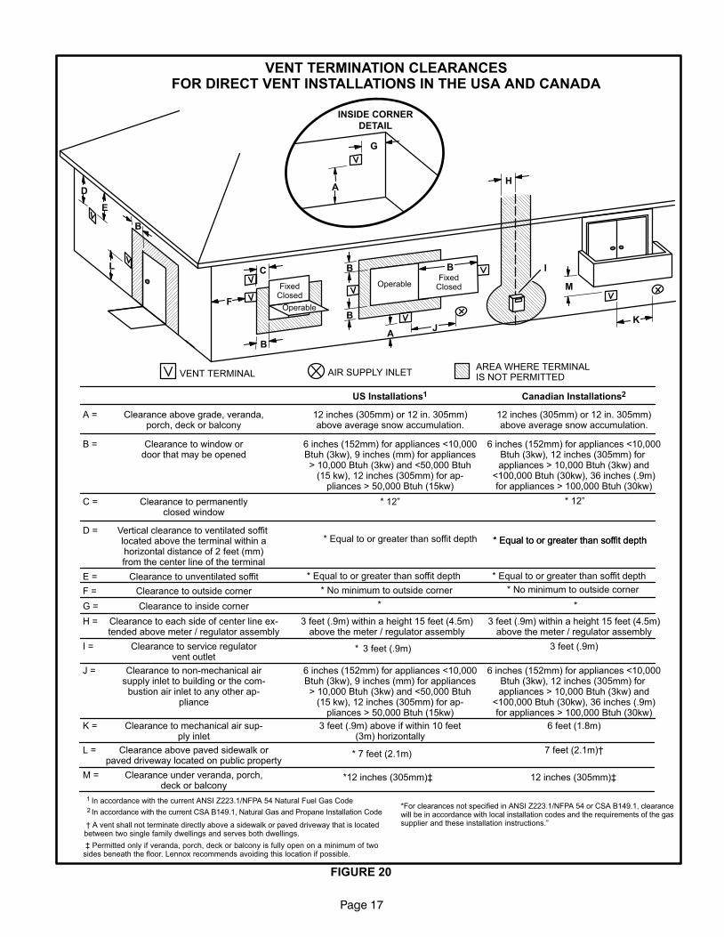
FIGURE 20
VENT TERMINATION CLEARANCESFOR DIRECT VENT INSTALLATIONS IN THE USA AND CANADA
K
D
E
L
B
C
F
G
A
B
JA
M
I
H
INSIDE CORNER
DETAIL
VENT TERMINAL AIR SUPPLY INLETAREA WHERE TERMINALIS NOT PERMITTED
FixedClosedOperable
B
FixedClosed
Operable
B
B
A =
B =
C =
D =
E =
F =
G =
H =
I =
J =
K =
L =
M =
US Installations1 Canadian Installations2
12 inches (305mm) or 12 in. 305mm)above average snow accumulation.
12 inches (305mm) or 12 in. 305mm)above average snow accumulation.
Clearance above grade, veranda,porch, deck or balcony
Clearance to window ordoor that may be opened
6 inches (152mm) for appliances <10,000Btuh (3kw), 9 inches (mm) for appliances> 10,000 Btuh (3kw) and <50,000 Btuh
(15 kw), 12 inches (305mm) for ap-pliances > 50,000 Btuh (15kw)
6 inches (152mm) for appliances <10,000Btuh (3kw), 12 inches (305mm) for appliances > 10,000 Btuh (3kw) and
<100,000 Btuh (30kw), 36 inches (.9m)for appliances > 100,000 Btuh (30kw)
Clearance to permanentlyclosed window
Vertical clearance to ventilated soffit located above the terminal within ahorizontal distance of 2 feet (mm)from the center line of the terminal
Clearance to unventilated soffit
Clearance to outside corner
Clearance to inside corner
Clearance to each side of center line ex-tended above meter / regulator assembly
Clearance to service regulatorvent outlet
Clearance to non−mechanical airsupply inlet to building or the com-
bustion air inlet to any other ap-pliance
Clearance to mechanical air sup-ply inlet
Clearance above paved sidewalk orpaved driveway located on public property
Clearance under veranda, porch,deck or balcony
* 12"
*
*
* 7 feet (2.1m)
3 feet (.9m) within a height 15 feet (4.5m)above the meter / regulator assembly
3 feet (.9m)
6 inches (152mm) for appliances <10,000Btuh (3kw), 9 inches (mm) for appliances> 10,000 Btuh (3kw) and <50,000 Btuh
(15 kw), 12 inches (305mm) for ap-pliances > 50,000 Btuh (15kw)
6 inches (152mm) for appliances <10,000Btuh (3kw), 12 inches (305mm) for appliances > 10,000 Btuh (3kw) and
<100,000 Btuh (30kw), 36 inches (.9m)for appliances > 100,000 Btuh (30kw)
3 feet (.9m) above if within 10 feet(3m) horizontally
6 feet (1.8m)
7 feet (2.1m)�
12 inches (305mm)�
1 In accordance with the current ANSI Z223.1/NFPA 54 Natural Fuel Gas Code
2 In accordance with the current CSA B149.1, Natural Gas and Propane Installation Code*For clearances not specified in ANSI Z223.1/NFPA 54 or CSA B149.1, clearancewill be in accordance with local installation codes and the requirements of the gassupplier and these installation instructions." � A vent shall not terminate directly above a sidewalk or paved driveway that is located
between two single family dwellings and serves both dwellings.
� Permitted only if veranda, porch, deck or balcony is fully open on a minimum of twosides beneath the floor. Lennox recommends avoiding this location if possible.
* 12"
* Equal to or greater than soffit depth * Equal to or greater than soffit depth* Equal to or greater than soffit depth
* Equal to or greater than soffit depth * Equal to or greater than soffit depth
* No minimum to outside corner * No minimum to outside corner
3 feet (.9m) within a height 15 feet (4.5m)above the meter / regulator assembly
3 feet (.9m)
*
*12 inches (305mm)�
Page 18
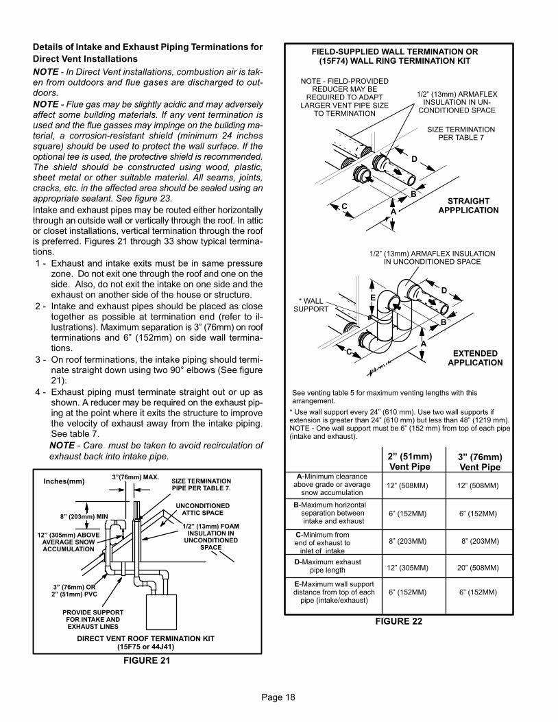
Details of Intake and Exhaust Piping Terminations for
Direct Vent Installations
NOTE − In Direct Vent installations, combustion air is tak-en from outdoors and flue gases are discharged to out-doors.
NOTE − Flue gas may be slightly acidic and may adverselyaffect some building materials. If any vent termination isused and the flue gasses may impinge on the building ma-terial, a corrosion−resistant shield (minimum 24 inchessquare) should be used to protect the wall surface. If theoptional tee is used, the protective shield is recommended.The shield should be constructed using wood, plastic,sheet metal or other suitable material. All seams, joints,cracks, etc. in the affected area should be sealed using anappropriate sealant. See figure 23.
Intake and exhaust pipes may be routed either horizontallythrough an outside wall or vertically through the roof. In atticor closet installations, vertical termination through the roofis preferred. Figures 21 through 33 show typical termina-tions.
1 − Exhaust and intake exits must be in same pressurezone. Do not exit one through the roof and one on theside. Also, do not exit the intake on one side and theexhaust on another side of the house or structure.
2 − Intake and exhaust pipes should be placed as closetogether as possible at termination end (refer to il-lustrations). Maximum separation is 3" (76mm) on roofterminations and 6" (152mm) on side wall termina-tions.
3 − On roof terminations, the intake piping should termi-nate straight down using two 90° elbows (See figure21).
4 − Exhaust piping must terminate straight out or up asshown. A reducer may be required on the exhaust pip-ing at the point where it exits the structure to improvethe velocity of exhaust away from the intake piping.See table 7.
NOTE − Care must be taken to avoid recirculation of
exhaust back into intake pipe.
FIGURE 21
UNCONDITIONEDATTIC SPACE
1/2" (13mm) FOAMINSULATION IN
UNCONDITIONEDSPACE
SIZE TERMINATIONPIPE PER TABLE 7.
3"(76mm) MAX.
12" (305mm) ABOVEAVERAGE SNOWACCUMULATION
3" (76mm) OR2" (51mm) PVC
PROVIDE SUPPORTFOR INTAKE ANDEXHAUST LINES
8" (203mm) MIN
Inches(mm)
DIRECT VENT ROOF TERMINATION KIT(15F75 or 44J41)
FIGURE 22
FIELD−SUPPLIED WALL TERMINATION OR(15F74) WALL RING TERMINATION KIT
See venting table 5 for maximum venting lengths with thisarrangement.
* Use wall support every 24" (610 mm). Use two wall supports ifextension is greater than 24" (610 mm) but less than 48" (1219 mm).NOTE − One wall support must be 6" (152 mm) from top of each pipe(intake and exhaust).
2" (51mm)Vent Pipe
3" (76mm)Vent Pipe
A−Minimum clearanceabove grade or average
snow accumulation
B−Maximum horizontal separation between intake and exhaust
C−Minimum fromend of exhaust to
inlet of intake
D−Maximum exhaustpipe length
E−Maximum wall supportdistance from top of each
pipe (intake/exhaust)
12" (508MM) 12" (508MM)
6" (152MM) 6" (152MM)
8" (203MM) 8" (203MM)
12" (305MM) 20" (508MM)
6" (152MM) 6" (152MM)
NOTE − FIELD−PROVIDEDREDUCER MAY BE
REQUIRED TO ADAPTLARGER VENT PIPE SIZE
TO TERMINATION
D
B
C
SIZE TERMINATIONPER TABLE 7
1/2" (13mm) ARMAFLEXINSULATION IN UN-
CONDITIONED SPACE
STRAIGHTAPPPLICATION
B
CA
D
* WALLSUPPORT
1/2" (13mm) ARMAFLEX INSULATIONIN UNCONDITIONED SPACE
E
EXTENDEDAPPLICATION
A
Page 19
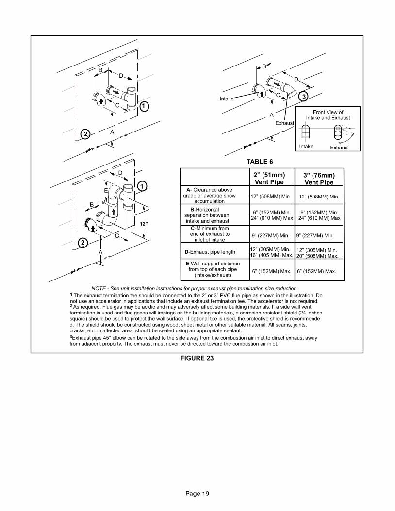
C
A
E
D
B
A
BD
D
B
C
A
C
12"
1
1
2
2
2" (51mm)Vent Pipe
3" (76mm)Vent Pipe
A− Clearance abovegrade or average snow
accumulation
B−Horizontal separation between intake and exhaust
C−Minimum fromend of exhaust to
inlet of intake
D−Exhaust pipe length
E−Wall support distancefrom top of each pipe
(intake/exhaust)
12" (508MM) Min. 12" (508MM) Min.
6" (152MM) Min.24" (610 MM) Max
9" (227MM) Min.
12" (305MM) Min.16" (405 MM) Max.
6" (152MM) Max.
6" (152MM) Min.24" (610 MM) Max
9" (227MM) Min.
12" (305MM) Min.20" (508MM) Max.
6" (152MM) Max.
TABLE 6
FIGURE 23
1 The exhaust termination tee should be connected to the 2" or 3" PVC flue pipe as shown in the illustration. Donot use an accelerator in applications that include an exhaust termination tee. The accelerator is not required.2 As required. Flue gas may be acidic and may adversely affect some building materials. If a side wall venttermination is used and flue gases will impinge on the building materials, a corrosion−resistant shield (24 inchessquare) should be used to protect the wall surface. If optional tee is used, the protective shield is recommende-d. The shield should be constructed using wood, sheet metal or other suitable material. All seams, joints,cracks, etc. in affected area, should be sealed using an appropriate sealant.3Exhaust pipe 45° elbow can be rotated to the side away from the combustion air inlet to direct exhaust awayfrom adjacent property. The exhaust must never be directed toward the combustion air inlet.
NOTE − See unit installation instructions for proper exhaust pipe termination size reduction.
Front View ofIntake and Exhaust
Intake Exhaust
3Intake
Exhaust
Page 20
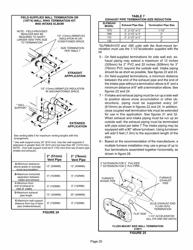
FIGURE 24
FIELD−SUPPLIED WALL TERMINATION OR(15F74) WALL RING TERMINATION KIT
With INTAKE ELBOW
See venting table 5 for maximum venting lengths with thisarrangement.
* Use wall support every 24" (610 mm). Use two wall supports ifextension is greater than 24" (610 mm) but less than 48" (1219 mm).NOTE − One wall support must be 6" (152 mm) from top of each pipe(intake and exhaust).
2" (51mm)Vent Pipe
3" (76mm)Vent Pipe
12" (508MM) 12" (508MM)
6" (152MM) 6" (152MM)
6" (152MM)
12" (305MM) 20" (508MM)
6" (152MM) 6" (152MM)
6" (152MM)
A−Minimum clearanceabove grade or average
snow accumulation
B−Maximum horizontal separation between intake and exhaust
C−Minimum fromend of exhaust to
inlet of intake
D−Maximum exhaustpipe length
E−Maximum wall supportdistance from top of each
pipe (intake/exhaust)
NOTE − FIELD−PROVIDEDREDUCER MAY BE
REQUIRED TO ADAPTLARGER VENT PIPE SIZE
TO TERMINATION.
D
B
C
SIZE TERMINATIONPER TABLE 7
1/2" (13mm) ARMAFLEXINSULATION IN UN-
CONDITIONED SPACE
STRAIGHTAPPPLICATION
B
C
D
* WALLSUPPORT
1/2" (13mm) ARMAFLEX INSULATIONIN UNCONDITIONED SPACE
E
EXTENDEDAPPLICATION
A
A
TABLE 7EXHAUST PIPE TERMINATION SIZE REDUCTION
SLP98UHVMODEL Exhaust Pipe Size Termination Pipe Size
*070 2", 2−1/2" or 3" 1−1/2"
*090 2", 2−1/2" or 3" 2"
110 2", 2−1/2" or 3" 2"
135 3" 2"
*SLP98UH−070 and −090 units with the flush−mount ter-mination must use the 1−1/2"accelerator supplied with thekit.
5 − On field−supplied terminations for side wall exit, ex-
haust piping may extend a maximum of 12 inches
(305mm) for 2" PVC and 20 inches (508mm) for 3"
(76mm) PVC beyond the outside wall. Intake piping
should be as short as possible. See figures 22 and 24.
6 − On field−supplied terminations, a minimum distance
between the end of the exhaust pipe and the end of
the intake pipe without a termination elbow is 8" and a
minimum distance of 6" with a termination elbow. See
figures 22 and 24.
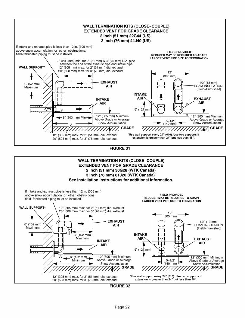
7 − If intake and exhaust piping must be run up a side wall
to position above snow accumulation or other ob-
structions, piping must be supported every 24"
(610mm) as shown in figures 22 and 24. In addition,
close coupled wall termination kits must be extended
for use in this application. See figures 31 and 32.
When exhaust and intake piping must be run up an
outside wall, the exhaust piping must be terminated
with pipe sized per table 7.The intake piping may be
equipped with a 90° elbow turndown. Using turndown
will add 5 feet (1.5m) to the equivalent length of the
pipe.
8 − Based on the recommendation of the manufacturer, a
multiple furnace installation may use a group of up to
four terminations assembled together horizontally, as
shown in figure 28.
2" EXTENSION FOR 2" PVC PIPE1" EXTENSION FOR 3" PVC PIPE
FIGURE 25
1−1/2" ACCELERATOR(ALL 070 AND 090 UNITS)
FURNACEEXHAUST
PIPE
FURNACEINTAKE PIPE
4’’
GLUE EXHAUST ENDFLUSH INTO
TERMINATION
FLAT SIDE
FLUSH−MOUNT SIDE WALL TERMINATION51W11
Page 21
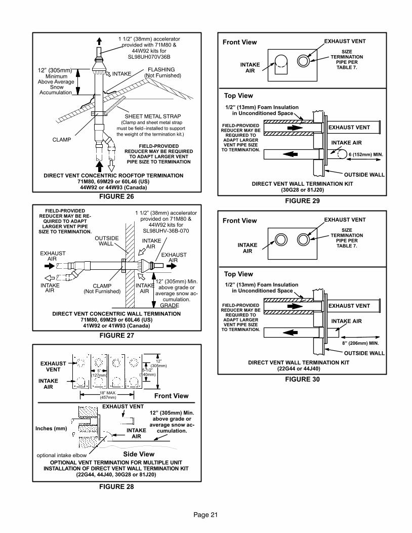
FIGURE 26
DIRECT VENT CONCENTRIC ROOFTOP TERMINATION71M80, 69M29 or 60L46 (US)44W92 or 44W93 (Canada)
MinimumAbove Average
SnowAccumulation
SHEET METAL STRAP(Clamp and sheet metal strap
must be field−installed to supportthe weight of the termination kit.)
FLASHING(Not Furnished)
CLAMPFIELD−PROVIDED
REDUCER MAY BE REQUIREDTO ADAPT LARGER VENT
PIPE SIZE TO TERMINATION
INTAKE
1 1/2" (38mm) acceleratorprovided with 71M80 &
44W92 kits forSL98UH070V36B
12” (305mm)
12" (305mm) Min.above grade or
average snow ac-cumulation.
FIGURE 27
DIRECT VENT CONCENTRIC WALL TERMINATION71M80, 69M29 or 60L46 (US)41W92 or 41W93 (Canada)
INTAKEAIR
EXHAUSTAIR
INTAKEAIR
INTAKEAIR
EXHAUSTAIR
OUTSIDEWALL
GRADE
CLAMP(Not Furnished)
FIELD−PROVIDEDREDUCER MAY BE RE-
QUIRED TO ADAPTLARGER VENT PIPE
SIZE TO TERMINATION.
1 1/2" (38mm) acceleratorprovided on 71M80 &
44W92 kits forSL98UHV−36B−070
FIGURE 28
EXHAUSTVENT
INTAKEAIR
5−1/2"(140mm)
Front View
12"(305mm)
5"(127mm)
18" MAX.(457mm)
EXHAUST VENT
INTAKEAIR
OPTIONAL VENT TERMINATION FOR MULTIPLE UNITINSTALLATION OF DIRECT VENT WALL TERMINATION KIT
(22G44, 44J40, 30G28 or 81J20)
Inches (mm)
Side View
12" (305mm) Min.above grade or
average snow ac-cumulation.
optional intake elbow
FIGURE 29
1/2" (13mm) Foam Insulation in Unconditioned Space
EXHAUST VENT
INTAKE AIR
OUTSIDE WALL
EXHAUST VENT
INTAKEAIR
Front View
Top View
DIRECT VENT WALL TERMINATION KIT(30G28 or 81J20)
6 (152mm) MIN.
SIZETERMINATION
PIPE PERTABLE 7.
FIELD−PROVIDEDREDUCER MAY BE
REQUIRED TOADAPT LARGERVENT PIPE SIZE
TO TERMINATION.
FIGURE 30
1/2" (13mm) Foam Insulation in Unconditioned Space
EXHAUST VENT
INTAKE AIR
OUTSIDE WALL
EXHAUST VENT
INTAKEAIR
Front View
Top View
DIRECT VENT WALL TERMINATION KIT(22G44 or 44J40)
8" (206mm) MIN.
SIZETERMINATION
PIPE PERTABLE 7.
FIELD−PROVIDEDREDUCER MAY BE
REQUIRED TOADAPT LARGERVENT PIPE SIZE
TO TERMINATION.
Page 22
FIGURE 31
ÉÉÉÉÉÉÉÉÉÉÉÉÉÉÉÉÉÉÉÉÉÉÉÉ
ÉÉÉÉÉÉÉÉÉÉÉÉÉÉÉÉÉÉÉÉÉÉ
12” (305 mm) MinimumAbove Grade or Average
Snow Accumulation
1/2” (13 mm)FOAM INSULATION
(Field−Furnished)
5” (127 mm)
5−1/2”(140 mm)
EXHAUSTAIR
INTAKEAIR
GRADE
12”(305 mm)
INTAKEAIR
EXHAUSTAIR
GRADE
12” (305 mm) max. for 2” (51 mm) dia. exhaust20” (508 mm) max. for 3” (76 mm) dia. exhaust
WALL SUPPORT*
12” (305 mm) max. for 2” (51 mm) dia. exhaust20” (508 mm) max. for 3” (76 mm) dia. exhaust
12” (305 mm) MinimumAbove Grade or Average
Snow Accumulation
WALL TERMINATION KITS (CLOSE−COUPLE)EXTENDED VENT FOR GRADE CLEARANCE
2 inch (51 mm) 22G44 (US)3 inch (76 mm) 44J40 (US)
6” (152 mm)Maximum
If intake and exhaust pipe is less than 12 in. (305 mm)above snow accumulation or other obstructions,field−fabricated piping must be installed.
8” (203 mm) min. for 2” (51 mm) & 3” (76 mm) DIA. pipebetween the end of the exhaust pipe and intake pipe
8” (203 mm) Min.
*Use wall support every 24" (610). Use two supports ifextension is greater than 24" but less than 48".
FIELD−PROVIDEDREDUCER MAY BE REQUIRED TO ADAPT
LARGER VENT PIPE SIZE TO TERMINATION
FIGURE 32
ÉÉÉÉÉÉÉÉÉÉÉÉ
12” (305 mm) MinimumAbove Grade or Average
Snow Accumulation
1/2” (13 mm)FOAM INSULATION
(Field−Furnished)
5” (127 mm)
5−1/2”(140 mm)
EXHAUSTAIR
INTAKEAIR
GRADE
12”(305 mm)
INTAKEAIR
EXHAUSTAIR
GRADE
WALL SUPPORT*
12” (305 mm) MinimumAbove Grade or Average
Snow Accumulation
WALL TERMINATION KITS (CLOSE−COUPLE)EXTENDED VENT FOR GRADE CLEARANCE
2 inch (51 mm) 30G28 (WTK Canada)3 inch (76 mm) 81J20 (WTK Canada)
See Installation Instructions for additional information.
6” (152 mm)Maximum
12” (305 mm) max. for 2” (51 mm) dia. exhaust20” (508 mm) max. for 3” (76 mm) dia. exhaust
12” (305 mm) max. for 2” (51 mm) dia. exhaust20” (508 mm) max. for 3” (76 mm) dia. exhaust
6” (152 mm)Minimum
6” (152 mm)Minimum
*Use wall support every 24" (610). Use two supports ifextension is greater than 24" but less than 48".
FIELD−PROVIDEDREDUCER MAY BE REQUIRED TO ADAPT
LARGER VENT PIPE SIZE TO TERMINATION
ÉÉÉÉÉÉÉÉÉÉÉ
If intake and exhaust pipe is less than 12 in. (305 mm)above snow accumulation or other obstructions,field−fabricated piping must be installed.
Page 23
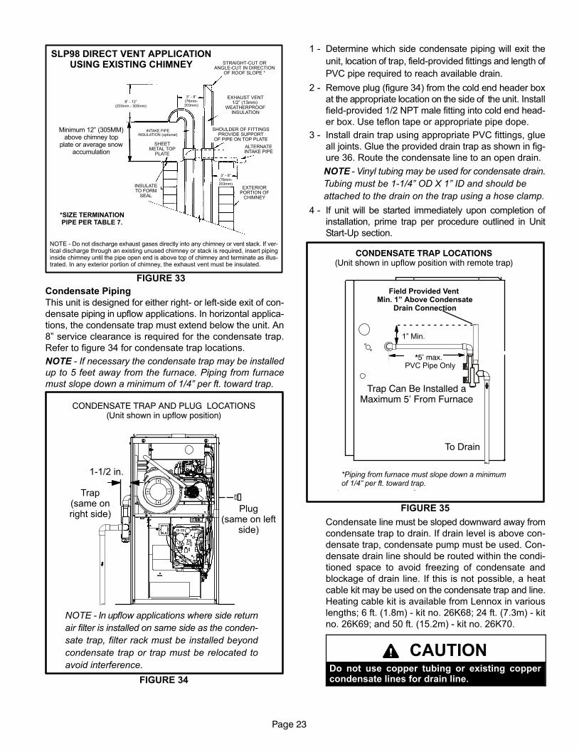
SLP98 DIRECT VENT APPLICATIONUSING EXISTING CHIMNEY
NOTE − Do not discharge exhaust gases directly into any chimney or vent stack. If ver-tical discharge through an existing unused chimney or stack is required, insert pipinginside chimney until the pipe open end is above top of chimney and terminate as illus-trated. In any exterior portion of chimney, the exhaust vent must be insulated.
FIGURE 33
8" − 12"(203mm − 305mm)
3" − 8"(76mm−203mm)
3" − 8"(76mm−203mm)
STRAIGHT−CUT ORANGLE−CUT IN DIRECTION
OF ROOF SLOPE *
EXHAUST VENT1/2" (13mm)
WEATHERPROOFINSULATION
SHOULDER OF FITTINGSPROVIDE SUPPORT
OF PIPE ON TOP PLATE
ALTERNATEINTAKE PIPE
INTAKE PIPEINSULATION (optional)
EXTERIORPORTION OF
CHIMNEY
INSULATETO FORM
SEAL
SHEETMETAL TOP
PLATE
*SIZE TERMINATIONPIPE PER TABLE 7.
Minimum 12" (305MM)above chimney top
plate or average snowaccumulation
Condensate Piping
This unit is designed for either right- or left-side exit of con-
densate piping in upflow applications. In horizontal applica-
tions, the condensate trap must extend below the unit. An
8" service clearance is required for the condensate trap.
Refer to figure 34 for condensate trap locations.
NOTE − If necessary the condensate trap may be installed
up to 5 feet away from the furnace. Piping from furnace
must slope down a minimum of 1/4" per ft. toward trap.
FIGURE 34
CONDENSATE TRAP AND PLUG LOCATIONS(Unit shown in upflow position)
NOTE − In upflow applications where side return
air filter is installed on same side as the conden-
sate trap, filter rack must be installed beyond
condensate trap or trap must be relocated to
avoid interference.
Trap(same onright side)
Plug(same on left
side)
1−1/2 in.
1 − Determine which side condensate piping will exit the
unit, location of trap, field−provided fittings and length of
PVC pipe required to reach available drain.
2 − Remove plug (figure 34) from the cold end header box
at the appropriate location on the side of the unit. Install
field−provided 1/2 NPT male fitting into cold end head-
er box. Use teflon tape or appropriate pipe dope.
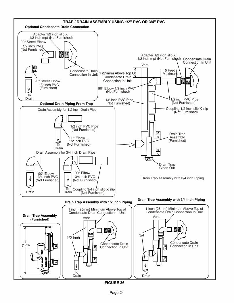
3 − Install drain trap using appropriate PVC fittings, glue
all joints. Glue the provided drain trap as shown in fig-
ure 36. Route the condensate line to an open drain.
NOTE − Vinyl tubing may be used for condensate drain.
Tubing must be 1−1/4" OD X 1" ID and should be
attached to the drain on the trap using a hose clamp.
4 − If unit will be started immediately upon completion of
installation, prime trap per procedure outlined in Unit
Start−Up section.
FIGURE 35
CONDENSATE TRAP LOCATIONS(Unit shown in upflow position with remote trap)
*5’ max.
To Drain
PVC Pipe Only
Field Provided Vent Min. 1" Above Condensate
Drain Connection
1" Min.
Trap Can Be Installed aMaximum 5’ From Furnace
*Piping from furnace must slope down a minimumof 1/4" per ft. toward trap.
Condensate line must be sloped downward away from
condensate trap to drain. If drain level is above con-
densate trap, condensate pump must be used. Con-
densate drain line should be routed within the condi-
tioned space to avoid freezing of condensate and
blockage of drain line. If this is not possible, a heat
cable kit may be used on the condensate trap and line.
Heating cable kit is available from Lennox in various
lengths; 6 ft. (1.8m) − kit no. 26K68; 24 ft. (7.3m) − kit
no. 26K69; and 50 ft. (15.2m) − kit no. 26K70.
CAUTIONDo not use copper tubing or existing coppercondensate lines for drain line.
Page 24
FIGURE 36
TRAP / DRAIN ASSEMBLY USING 1/2" PVC OR 3/4" PVC
Adapter 1/2 inch slip X1/2 inch mpt (Not Furnished)
Drain TrapAssembly
(Furnished)
Vent
Drain TrapClean Out
5 FeetMaximum
Coupling 1/2 inch slip X slip(Not Furnished)
90° Elbow 1/2 inch PVC(Not Furnished)
1/2 inch PVC Pipe(Not Furnished)
1/2 inch PVC Pipe(Not Furnished)
Condensate DrainConnection In Unit
7(178)
Drain Assembly for 1/2 inch Drain Pipe
90° Elbow 3/4 inch PVC
(Not Furnished)
Coupling 3/4 inch slip X slip(Not Furnished)
ToDrain
ToDrain
90° Elbow 3/4 inch PVC
(Not Furnished)
ToDrain
90° Street Elbow 1/2 inch PVC
ToDrain
90° Elbow 1/2 inch PVC
(Not Furnished)
1/2 inch PVC Pipe(Not Furnished)
Drain Assembly for 3/4 inch Drain Pipe
90° Street Elbow 1/2 inch PVC
(Not Furnished)
Condensate DrainConnection In Unit
Adapter 1/2 inch slip X1/2 inch mpt (Not Furnished)
1 inch (25mm) Minimum Above Top ofCondensate Drain Connection In Unit
Condensate DrainConnection In Unit
Vent
ToDrain
1 inch (25mm) Minimum Above Top ofCondensate Drain Connection In Unit
Condensate DrainConnection In Unit
Drain Trap Assembly with 3/4 inch Piping
Vent
ToDrain
(Furnished)
1 (25mm) Above Top OfCondensate DrainConnection In Unit
Optional Condensate Drain Connection
Optional Drain Piping From Trap
Drain Trap Assembly(Furnished)
Drain Trap Assembly with 1/2 inch PipingDrain Trap Assembly with 3/4 inch Piping
1/2 inch3/4
Page 25
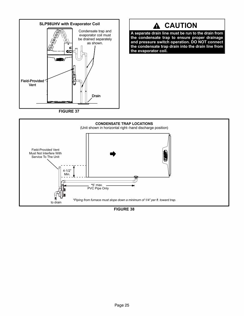
FIGURE 37
SLP98UHV with Evaporator Coil
Drain
Condensate trap andevaporator coil must
be drained separatelyas shown.
Field−ProvidedVent
Drain
Field−ProvidedVent
CAUTIONA separate drain line must be run to the drain fromthe condensate trap to ensure proper drainageand pressure switch operation. DO NOT connectthe condensate trap drain into the drain line fromthe evaporator coil.
FIGURE 38
CONDENSATE TRAP LOCATIONS(Unit shown in horizontal right−hand discharge position)
*5’ max.
to drain
PVC Pipe Only
4−1/2"Min.
Field−Provided VentMust Not Interfere With
Service To The Unit
*Piping from furnace must slope down a minimum of 1/4" per ft. toward trap.
Page 26
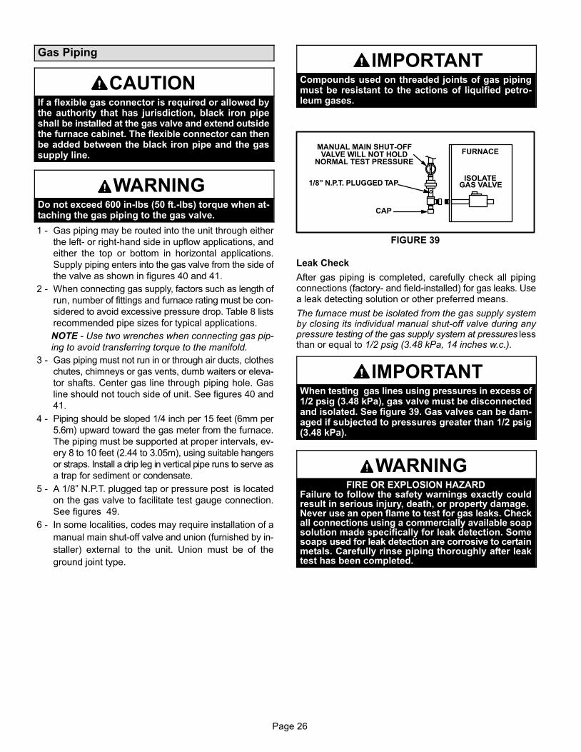
Gas Piping
CAUTIONIf a flexible gas connector is required or allowed bythe authority that has jurisdiction, black iron pipeshall be installed at the gas valve and extend outsidethe furnace cabinet. The flexible connector can thenbe added between the black iron pipe and the gassupply line.
WARNINGDo not exceed 600 in−lbs (50 ft.−lbs) torque when at-taching the gas piping to the gas valve.
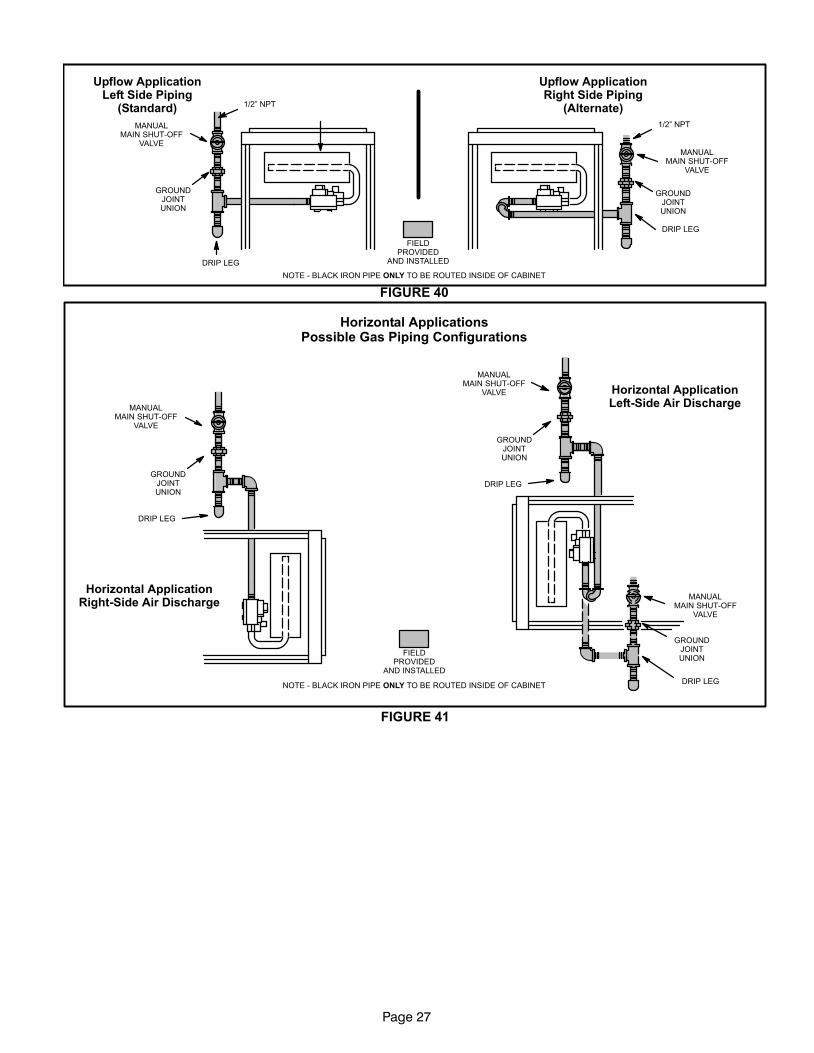
1 − Gas piping may be routed into the unit through either
the left- or right-hand side in upflow applications, and
either the top or bottom in horizontal applications.
Supply piping enters into the gas valve from the side of
the valve as shown in figures 40 and 41.
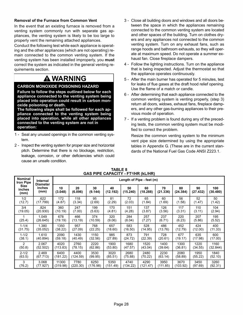
2 − When connecting gas supply, factors such as length of
run, number of fittings and furnace rating must be con-
sidered to avoid excessive pressure drop. Table 8 lists
recommended pipe sizes for typical applications.
NOTE − Use two wrenches when connecting gas pip-
ing to avoid transferring torque to the manifold.
3 − Gas piping must not run in or through air ducts, clothes
chutes, chimneys or gas vents, dumb waiters or eleva-
tor shafts. Center gas line through piping hole. Gas
line should not touch side of unit. See figures 40 and
41.
4 − Piping should be sloped 1/4 inch per 15 feet (6mm per
5.6m) upward toward the gas meter from the furnace.
The piping must be supported at proper intervals, ev-
ery 8 to 10 feet (2.44 to 3.05m), using suitable hangers
or straps. Install a drip leg in vertical pipe runs to serve as
a trap for sediment or condensate.
5 − A 1/8" N.P.T. plugged tap or pressure post is located
on the gas valve to facilitate test gauge connection.
See figures 49.
6 − In some localities, codes may require installation of a
manual main shut-off valve and union (furnished by in-
staller) external to the unit. Union must be of the
ground joint type.
IMPORTANTCompounds used on threaded joints of gas pipingmust be resistant to the actions of liquified petro-leum gases.
FIGURE 39
MANUAL MAIN SHUT−OFFVALVE WILL NOT HOLD
NORMAL TEST PRESSURE
CAP
FURNACE
ISOLATEGAS VALVE1/8" N.P.T. PLUGGED TAP
Leak Check
After gas piping is completed, carefully check all pipingconnections (factory− and field−installed) for gas leaks. Usea leak detecting solution or other preferred means.
The furnace must be isolated from the gas supply systemby closing its individual manual shut-off valve during anypressure testing of the gas supply system at pressures lessthan or equal to 1/2 psig (3.48 kPa, 14 inches w.c.).
IMPORTANTWhen testing gas lines using pressures in excess of1/2 psig (3.48 kPa), gas valve must be disconnectedand isolated. See figure 39. Gas valves can be dam-aged if subjected to pressures greater than 1/2 psig(3.48 kPa).
WARNINGFIRE OR EXPLOSION HAZARD
Failure to follow the safety warnings exactly couldresult in serious injury, death, or property damage.Never use an open flame to test for gas leaks. Checkall connections using a commercially available soapsolution made specifically for leak detection. Somesoaps used for leak detection are corrosive to certainmetals. Carefully rinse piping thoroughly after leaktest has been completed.
Page 27
GROUNDJOINTUNION
FIELDPROVIDED
AND INSTALLED
Upflow ApplicationLeft Side Piping
(Standard)
DRIP LEG
MANUALMAIN SHUT−OFF
VALVE
GROUNDJOINTUNION
DRIP LEG
MANUALMAIN SHUT−OFF
VALVE
Upflow ApplicationRight Side Piping
(Alternate)
FIGURE 40
1/2" NPT
1/2" NPT
NOTE − BLACK IRON PIPE ONLY TO BE ROUTED INSIDE OF CABINET
GROUNDJOINTUNION
DRIP LEG
MANUALMAIN SHUT−OFF
VALVE
GROUNDJOINTUNION
DRIP LEG
MANUALMAIN SHUT−OFF
VALVE
GROUNDJOINTUNION
DRIP LEG
MANUALMAIN SHUT−OFF
VALVE
Horizontal ApplicationsPossible Gas Piping Configurations
Horizontal ApplicationLeft−Side Air Discharge
Horizontal ApplicationRight−Side Air Discharge
NOTE − BLACK IRON PIPE ONLY TO BE ROUTED INSIDE OF CABINET
FIELDPROVIDED
AND INSTALLED
FIGURE 41
Page 28
Removal of the Furnace from Common Vent
In the event that an existing furnace is removed from a
venting system commonly run with separate gas ap-
pliances, the venting system is likely to be too large to
properly vent the remaining attached appliances.
Conduct the following test while each appliance is operat-
ing and the other appliances (which are not operating) re-
main connected to the common venting system. If the
venting system has been installed improperly, you must
correct the system as indicated in the general venting re-
quirements section.
WARNINGCARBON MONOXIDE POISONING HAZARD
Failure to follow the steps outlined below for eachappliance connected to the venting system beingplaced into operation could result in carbon mon-oxide poisoning or death.The following steps shall be followed for each ap-pliance connected to the venting system beingplaced into operation, while all other appliancesconnected to the venting system are not inoperation:
1 − Seal any unused openings in the common venting sys-
tem.
2 − Inspect the venting system for proper size and horizontal
pitch. Determine that there is no blockage, restriction,
leakage, corrosion, or other deficiencies which could
cause an unsafe condition.
3 − Close all building doors and windows and all doors be-
tween the space in which the appliances remaining
connected to the common venting system are located
and other spaces of the building. Turn on clothes dry-
ers and any appliances not connected to the common
venting system. Turn on any exhaust fans, such as
range hoods and bathroom exhausts, so they will oper-
ate at maximum speed. Do not operate a summer ex-
haust fan. Close fireplace dampers.
4 − Follow the lighting instructions. Turn on the appliance
that is being inspected. Adjust the thermostat so that
the appliance operates continuously.
5 − After the main burner has operated for 5 minutes, test
for leaks of flue gases at the draft hood relief opening.
Use the flame of a match or candle.
6 − After determining that each appliance connected to the
common venting system is venting properly, (step 3)
return all doors, widows, exhaust fans, fireplace damp-
ers, and any other gas−burning appliances to their pre-
vious mode of operation.
7 − If a venting problem is found during any of the preced-
ing tests, the common venting system must be modi-
fied to correct the problem.
Resize the common venting system to the minimum
vent pipe size determined by using the appropriate
tables in Appendix G. (These are in the current stan-
dards of the National Fuel Gas Code ANSI Z223.1.
TABLE 8GAS PIPE CAPACITY − FT3/HR (kL/HR)
NominalIron Pipe
Sizeinches(mm)
InternalDiameterinches(mm)
Length of Pipe − feet (m)
10(3.048)
20(6.096)
30(9.144)
40(12.192)
50(15.240)
60(18.288)
70(21.336)
80(24.384)
90(27.432)
100(30.480)
1/2(12.7)
.622(17.799)
172(4.87)
118(3.34)
95(2.69)
81(2.29)
72(2.03)
65(1.84)
60(1.69)
56(1.58)
52(1.47)
50(1.42)
3/4(19.05)
.824(20.930)
360(10.19)
247(7.00)
199(5.63)
170(4.81)
151(4.28)
137(3.87)
126(3.56)
117(3.31)
110(3.11)
104(2.94)
1(25.4)
1.049(26.645)
678(19.19)
466(13.19)
374(10.59)
320(9.06)
284(8.04)
257(7.27)
237(6.71)
220(6.23)
207(5.86)
195(5.52)
1−1/4(31.75)
1.380(35.052)
1350(38.22)
957(27.09)
768(22.25)
657(18.60)
583(16.50)
528(14.95)
486(13.76)
452(12.79)
424(12.00)
400(11.33)
1−1/2(38.1)
1.610(40.894)
2090(59.18)
1430(40.49)
1150(32.56)
985(27.89)
873(24.72)
791(22.39)
728(20.61)
677(19.17)
635(17.98)
600(17.00)
2(50.8)
2.067(52.502)
4020(113.83)
2760(78.15)
2220(62.86)
1900(53.80)
1680(47.57)
1520(43.04)
1400(39.64)
1300(36.81)
1220(34.55)
1160(32.844)
2−1/2(63.5)
2.469(67.713)
6400(181.22)
4400(124.59)
3530(99.95)
3020(85.51)
2680(75.88)
2480(70.22)
2230(63.14)
2080(58.89)
1950(55.22)
1840(52.10)
3(76.2)
3.068(77.927)
11300(319.98)
7780(220.30)
6250(176.98)
5350(151.49)
4740(134.22)
4290(121.47)
3950(111.85)
3670(103.92)
3450(97.69)
3260(92.31)
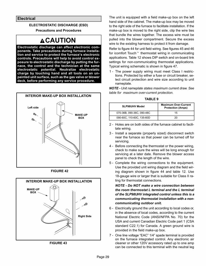
Page 29
Electrical
ELECTROSTATIC DISCHARGE (ESD)
Precautions and Procedures
CAUTIONElectrostatic discharge can affect electronic com-ponents. Take precautions during furnace installa-tion and service to protect the furnace’s electroniccontrols. Precautions will help to avoid control ex-posure to electrostatic discharge by putting the fur-nace, the control and the technician at the sameelectrostatic potential. Neutralize electrostaticcharge by touching hand and all tools on an un-painted unit surface, such as the gas valve or blowerdeck, before performing any service procedure.
INTERIOR MAKE−UP BOX INSTALLATION
FIGURE 42
MAKE−UPBOX
Left side
INTERIOR MAKE−UP BOX INSTALLATION
MAKE−UPBOX
Right Side
FIGURE 43
The unit is equipped with a field make−up box on the left
hand side of the cabinet. The make−up box may be moved
to the right side of the furnace to facilitate installation. If the
make−up box is moved to the right side, clip the wire ties
that bundle the wires together. The excess wire must be
pulled into the blower compartment. Secure the excess
wire to the existing harness to protect it from damage.
Refer to figure 44 for unit field wiring. See figures 45 and 46
for icomfort Touch� thermostat wiring in communicating
applications. Table 12 shows DIP switch and on−board link
settings for non−communicating thermostat applications.
Typical wiring schematic is shown in figure 47.
1 − The power supply wiring must meet Class I restric-
tions. Protected by either a fuse or circuit breaker, se-
lect circuit protection and wire size according to unit
nameplate.
NOTE − Unit nameplate states maximum current draw. See
table for maximum over−current protection.
TABLE 9
SLP98UHV ModelMaximum Over−Current
Protection (Amps)
070−36B, 090−36C, 090−48C 15
090−60C, 110−60C, 135−60D 20
2 − Holes are on both sides of the furnace cabinet to facili-
tate wiring.
3 − Install a separate (properly sized) disconnect switch
near the furnace so that power can be turned off for
servicing.
4 − Before connecting the thermostat or the power wiring,
check to make sure the wires will be long enough for
servicing at a later date. Remove the blower access
panel to check the length of the wire.
5 − Complete the wiring connections to the equipment.
Use the provided unit wiring diagram and the field wir-
ing diagram shown in figure 44 and table 12. Use
18−gauge wire or larger that is suitable for Class II ra-
ting for thermostat connections.
NOTE − Do NOT make a wire connection between
the room thermostat L terminal and the L terminal
of the SLP98UHV integrated control unless this is a
communicating thermostat installation with a non−
communicating outdoor unit.
6 − Electrically ground the unit according to local codes or,
in the absence of local codes, according to the current
National Electric Code (ANSI/NFPA No. 70) for the
USA and current Canadian Electric Code part 1 (CSA
standard C22.1) for Canada. A green ground wire is
provided in the field make−up box.
7 − One line voltage �EAC" 1/4" spade terminal is providedon the furnace integrated control. Any electronic aircleaner or other 120V accessory rated up to one ampcan be connected to this terminal with the neutral leg
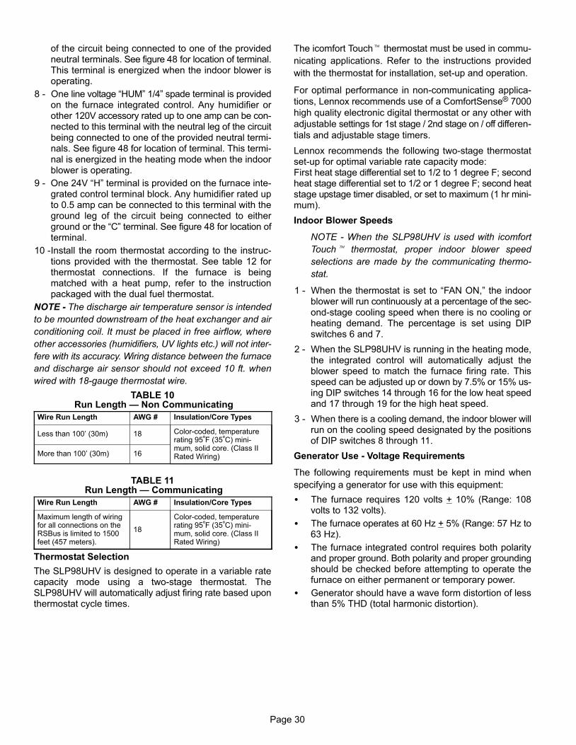
Page 30
of the circuit being connected to one of the providedneutral terminals. See figure 48 for location of terminal.This terminal is energized when the indoor blower isoperating.
8 − One line voltage �HUM" 1/4" spade terminal is providedon the furnace integrated control. Any humidifier orother 120V accessory rated up to one amp can be con-nected to this terminal with the neutral leg of the circuitbeing connected to one of the provided neutral termi-nals. See figure 48 for location of terminal. This termi-nal is energized in the heating mode when the indoorblower is operating.
9 − One 24V �H" terminal is provided on the furnace inte-grated control terminal block. Any humidifier rated upto 0.5 amp can be connected to this terminal with theground leg of the circuit being connected to eitherground or the �C" terminal. See figure 48 for location ofterminal.
10 −Install the room thermostat according to the instruc-tions provided with the thermostat. See table 12 forthermostat connections. If the furnace is beingmatched with a heat pump, refer to the instructionpackaged with the dual fuel thermostat.
NOTE − The discharge air temperature sensor is intended
to be mounted downstream of the heat exchanger and air
conditioning coil. It must be placed in free airflow, where
other accessories (humidifiers, UV lights etc.) will not inter-
fere with its accuracy. Wiring distance between the furnace
and discharge air sensor should not exceed 10 ft. when
wired with 18−gauge thermostat wire.
TABLE 10 Run Length � Non Communicating
Wire Run Length AWG # Insulation/Core Types
Less than 100’ (30m) 18 Color−coded, temperaturerating 95ºF (35ºC) mini-mum, solid core. (Class IIRated Wiring)More than 100’ (30m) 16
TABLE 11 Run Length � Communicating
Wire Run Length AWG # Insulation/Core Types
Maximum length of wiringfor all connections on theRSBus is limited to 1500feet (457 meters).
18
Color−coded, temperaturerating 95ºF (35ºC) mini-mum, solid core. (Class IIRated Wiring)
Thermostat Selection
The SLP98UHV is designed to operate in a variable ratecapacity mode using a two−stage thermostat. TheSLP98UHV will automatically adjust firing rate based uponthermostat cycle times.
The icomfort Touch� thermostat must be used in commu-
nicating applications. Refer to the instructions provided
with the thermostat for installation, set−up and operation.
For optimal performance in non−communicating applica-
tions, Lennox recommends use of a ComfortSense® 7000
high quality electronic digital thermostat or any other with
adjustable settings for 1st stage / 2nd stage on / off differen-
tials and adjustable stage timers.
Lennox recommends the following two−stage thermostatset−up for optimal variable rate capacity mode:First heat stage differential set to 1/2 to 1 degree F; secondheat stage differential set to 1/2 or 1 degree F; second heatstage upstage timer disabled, or set to maximum (1 hr mini-mum).
Indoor Blower Speeds
NOTE − When the SLP98UHV is used with icomfort
Touch� thermostat, proper indoor blower speed
selections are made by the communicating thermo-
stat.
1 − When the thermostat is set to �FAN ON," the indoorblower will run continuously at a percentage of the sec-ond−stage cooling speed when there is no cooling orheating demand. The percentage is set using DIPswitches 6 and 7.
2 − When the SLP98UHV is running in the heating mode,the integrated control will automatically adjust theblower speed to match the furnace firing rate. Thisspeed can be adjusted up or down by 7.5% or 15% us-ing DIP switches 14 through 16 for the low heat speedand 17 through 19 for the high heat speed.
3 − When there is a cooling demand, the indoor blower willrun on the cooling speed designated by the positionsof DIP switches 8 through 11.
Generator Use − Voltage Requirements
The following requirements must be kept in mind when
specifying a generator for use with this equipment:
� The furnace requires 120 volts + 10% (Range: 108volts to 132 volts).
� The furnace operates at 60 Hz + 5% (Range: 57 Hz to63 Hz).
� The furnace integrated control requires both polarityand proper ground. Both polarity and proper groundingshould be checked before attempting to operate thefurnace on either permanent or temporary power.
� Generator should have a wave form distortion of lessthan 5% THD (total harmonic distortion).
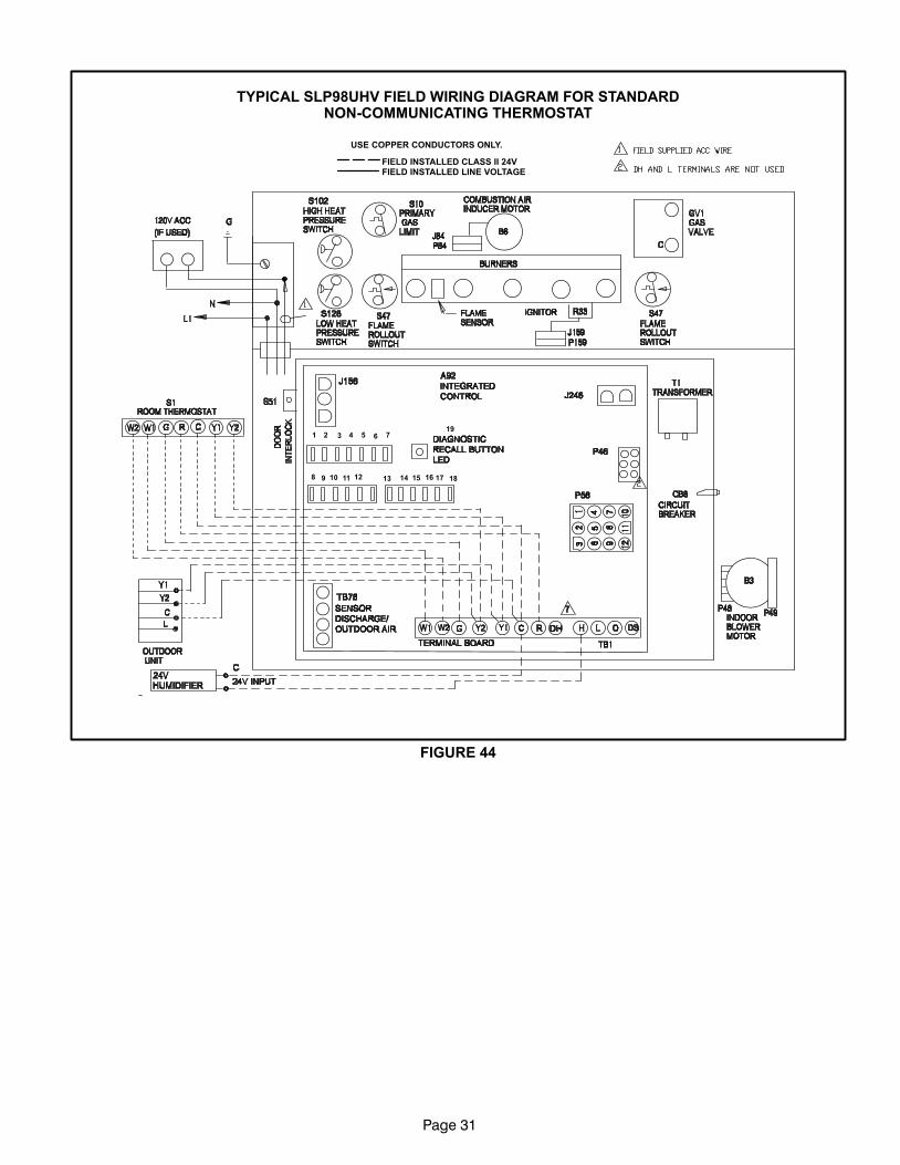
Page 31
TYPICAL SLP98UHV FIELD WIRING DIAGRAM FOR STANDARDNON−COMMUNICATING THERMOSTAT
FIGURE 44
FIELD INSTALLED CLASS II 24VFIELD INSTALLED LINE VOLTAGE
USE COPPER CONDUCTORS ONLY.
1 2 3 4 5 6 7
8 9 10 11 12 13 14 15 16 17 18
19
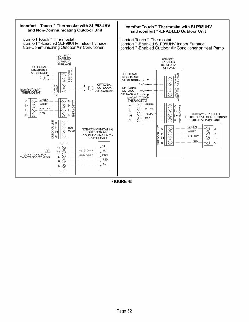
Page 32
FIGURE 45
icomfort Touch� Thermostat with SLP98UHVand Non−Communicating Outdoor Unit
icomfort�−ENABLEDSLP98UHVFURNACE
icomfort Touch�THERMOSTAT
NON−COMMUNICATINGOUTDOOR AIR
CONDITIONING UNIT −1 OR 2 STAGE
icomfort Touch� Thermostaticomfort�−Enabled SLP98UHV Indoor FurnaceNon−Communicating Outdoor Air Conditioner
OPTIONALOUTDOOR
AIR SENSOR
OPTIONALDISCHARGEAIR SENSOR
icomfort Touch� Thermostat with SLP98UHVand icomfort�−ENABLED Outdoor Unit
icomfort Touch� Thermostaticomfort�−Enabled SLP98UHV Indoor Furnaceicomfort�−Enabled Outdoor Air Conditioner or Heat Pump
icomfort�−ENABLEDSLP98UHVFURNACE
icomfort� TOUCHTHERMOSTAT
icomfort�− ENABLEDOUTDOOR AIR CONDITIONING
OR HEAT PUMP UNIT
OPTIONALOUTDOOR
AIR SENSOR
OPTIONALDISCHARGEAIR SENSOR
CLIP Y1 TO Y2 FORTWO−STAGE OPERATION
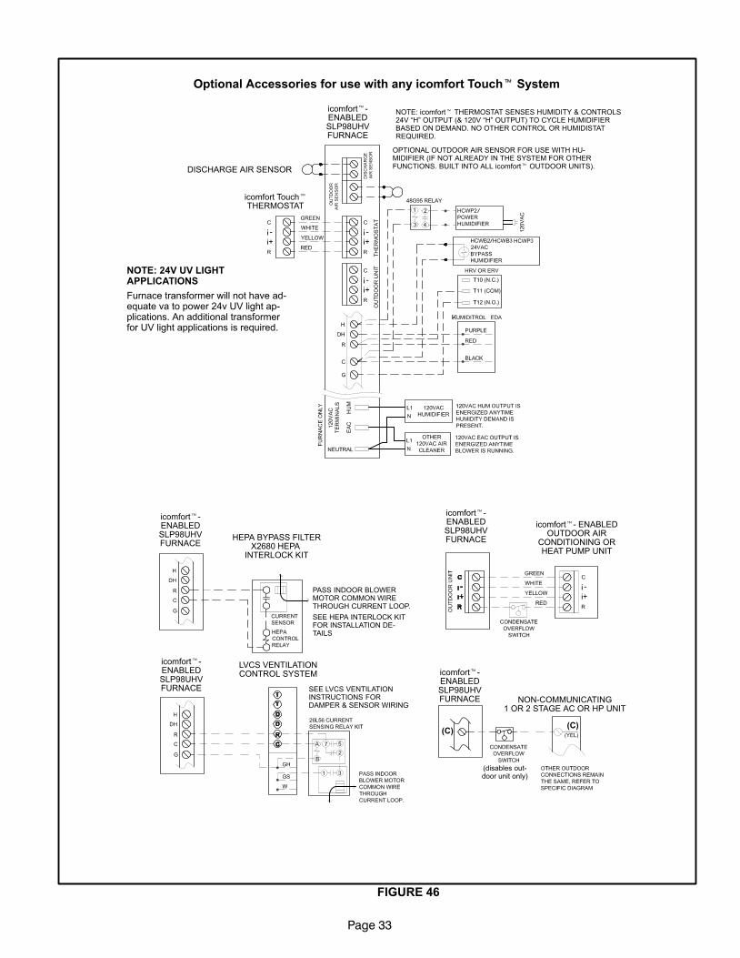
Page 33
FIGURE 46
Optional Accessories for use with any icomfort Touch� System
NOTE: 24V UV LIGHTAPPLICATIONS
Furnace transformer will not have ad-equate va to power 24v UV light ap-plications. An additional transformerfor UV light applications is required.
icomfort Touch�THERMOSTAT
DISCHARGE AIR SENSOR
NOTE: icomfort� THERMOSTAT SENSES HUMIDITY & CONTROLS24V �H" OUTPUT (& 120V �H" OUTPUT) TO CYCLE HUMIDIFIERBASED ON DEMAND. NO OTHER CONTROL OR HUMIDISTATREQUIRED.
OPTIONAL OUTDOOR AIR SENSOR FOR USE WITH HU-MIDIFIER (IF NOT ALREADY IN THE SYSTEM FOR OTHERFUNCTIONS. BUILT INTO ALL icomfort� OUTDOOR UNITS).
icomfort�−ENABLEDSLP98UHVFURNACE
HEPA BYPASS FILTERX2680 HEPA
INTERLOCK KIT
PASS INDOOR BLOWERMOTOR COMMON WIRETHROUGH CURRENT LOOP.
SEE HEPA INTERLOCK KITFOR INSTALLATION DE-TAILS
LVCS VENTILATIONCONTROL SYSTEM
SEE LVCS VENTILATIONINSTRUCTIONS FORDAMPER & SENSOR WIRING
icomfort�− ENABLEDOUTDOOR AIR
CONDITIONING ORHEAT PUMP UNIT
NON−COMMUNICATING1 OR 2 STAGE AC OR HP UNIT
icomfort�−ENABLEDSLP98UHVFURNACE
icomfort�−ENABLEDSLP98UHVFURNACE
icomfort�−ENABLEDSLP98UHVFURNACE
icomfort�−ENABLEDSLP98UHVFURNACE
(C)(C)
(disables out-door unit only)
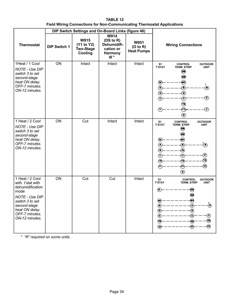
Page 34
TABLE 12
Field Wiring Connections for Non−Communicating Thermostat Applications
Thermostat
DIP Switch Settings and On−Board Links (figure 48)
Wiring ConnectionsDIP Switch 1
W915(Y1 to Y2)Two−Stage
Cooling
W914(DS to R)
Dehumidifi-cation orHarmony
III�
W951(O to R)
Heat Pumps
1Heat / 1 Cool
NOTE − Use DIPswitch 3 to setsecond−stageheat ON delay.OFF−7 minutes.ON−12 minutes.
ON Intact Intact Intact S1T’STAT
CONTROLTERM. STRIP
OUTDOORUNIT
*
1 Heat / 2 Cool
NOTE − Use DIPswitch 3 to setsecond−stageheat ON delay.OFF−7 minutes.ON−12 minutes.
ON Cut Intact Intact S1T’STAT
CONTROLTERM. STRIP
OUTDOORUNIT
*
1 Heat / 2 Coolwith t’stat withdehumidificationmode
NOTE − Use DIPswitch 3 to setsecond−stageheat ON delay.OFF−7 minutes.ON−12 minutes.
ON Cut Cut Intact S1T’STAT
CONTROLTERM. STRIP
OUTDOORUNIT
*
* �R" required on some units.
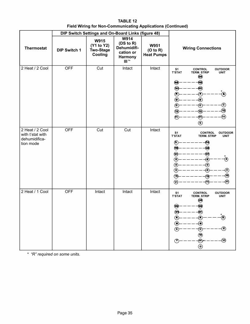
Page 35
TABLE 12
Field Wiring for Non−Communicating Applications (Continued)
Thermostat
DIP Switch Settings and On−Board Links (figure 48)
Wiring ConnectionsDIP Switch 1
W915(Y1 to Y2)Two−Stage
Cooling
W914(DS to R)
Dehumidifi-cation orHarmony
III�
W951(O to R)
Heat Pumps
2 Heat / 2 Cool OFF Cut Intact Intact S1T’STAT
CONTROLTERM. STRIP
OUTDOORUNIT
*
2 Heat / 2 Coolwith t’stat withdehumidifica-tion mode
OFF Cut Cut IntactS1
T’STATCONTROL
TERM. STRIPOUTDOOR
UNIT
*
2 Heat / 1 Cool OFF Intact Intact Intact S1T’STAT
CONTROLTERM. STRIP
OUTDOORUNIT
*
* �R" required on some units.
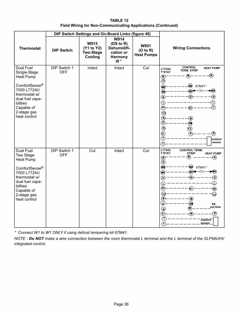
Page 36
TABLE 12
Field Wiring for Non−Communicating Applications (Continued)
Thermostat
DIP Switch Settings and On−Board Links (figure 48)
Wiring ConnectionsDIP Switch
W915(Y1 to Y2)Two−Stage
Cooling
W914(DS to R)
Dehumidifi-cation orHarmony
III�
W951(O to R)
Heat Pumps
Dual FuelSingle−StageHeat Pump
ComfortSense®
7000 L7724Uthermostat w/dual fuel capa-bilitiesCapable of2−stage gasheat control
DIP Switch 1OFF
Intact Intact Cut L7724UT’STAT
CONTROLTERM. STRIP
HEAT PUMP
67M41*
Y
H
L
Y2
D
B
L
Y2
T
T
outdoorsensor
Dual FuelTwo StageHeat Pump
ComfortSense®
7000 L7724Uthermostat w/dual fuel capa-bilitiesCapable of2−stage gasheat control
DIP Switch 1OFF
Cut Intact Cut CONTROL TERM.STRIP HEAT PUMP
out blue
67M41*
H
L
Y2
D
B
L
Y2
T
T
outdoorsensor
L7724UT’STAT
* Connect W1 to W1 ONLY if using defrost tempering kit 67M41.
NOTE − Do NOT make a wire connection between the room thermostat L terminal and the L terminal of the SLP98UHV
integrated control.
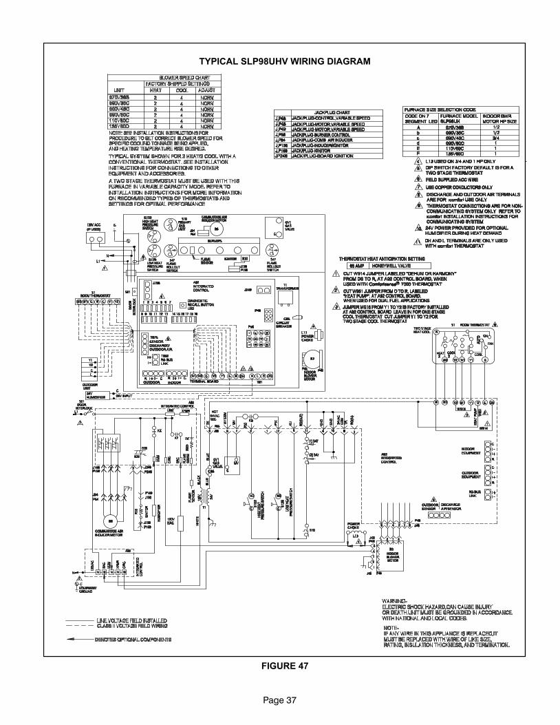
Page 37
FIGURE 47
TYPICAL SLP98UHV WIRING DIAGRAM
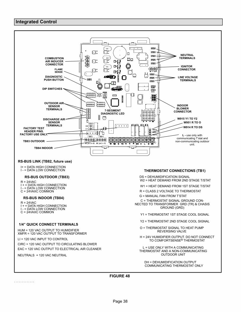
Page 38
Integrated Control
FIGURE 48
THERMOSTAT CONNECTIONS (TB1)
1/4" QUICK CONNECT TERMINALS
RS−BUS LINK (TB82, future use)
I+ = DATA HIGH CONNECTIONI − = DATA LOW CONNECTION
RS−BUS OUTDOOR (TB83)
R = 24VACI + = DATA HIGH CONNECTIONI − = DATA LOW CONNECTIONC = 24VAXC COMMON
RS−BUS INDOOR (TB84)
R = 24VACI + = DATA HIGH CONNECTIONI − = DATA LOW CONNECTIONC = 24VAXC COMMON
+
FLAMESENSE
COMBUSTIONAIR INDUCERCONNECTOR
DIP SWITCHES
OUTDOOR AIRSENSOR
TERMINALS
DISCHARGE AIRSENSOR
TERMINALS
W915
W951
W914
INDOORBLOWER
CONNECTOR
EAC
HUM
LINE VOLTAGETERMINALS
NEUTRALTERMINALS
IGNITORCONNECTOR
7−SEGMENTDIAGNOSTIC LED
DIAGNOSTICPUSH BUTTON
FACTORY TESTHEADER PINS.
FACTORY USE ONLY.
TB83 OUTDOOR
TB84 INDOOR
DS = DEHUMIDIFICATION SIGNALW2 = HEAT DEMAND FROM 2ND STAGE T/STAT
W1 = HEAT DEMAND FROM 1ST STAGE T/STAT
R = CLASS 2 VOLTAGE TO THERMOSTAT
G = MANUAL FAN FROM T’STAT
C = THERMOSTAT SIGNAL GROUND CON-NECTED TO TRANSFORMER GRD (TR) & CHASIS
GROUND (GRD)
Y1 = THERMOSTAT 1ST STAGE COOL SIGNAL
Y2 = THERMOSTAT 2ND STAGE COOL SIGNAL
O = THERMOSTAT SIGNAL TO HEAT PUMPREVERSING VALVE
H = 24V HUMIDIFIER OUTPUT. DO NOT CONNECTTO COMFORTSENSE® THERMOSTAT
L = USE ONLY WITH A COMMUNICATINGTHERMOSTAT AND A NON−COMMUNICATING
OUTDOOR UNIT
DH = DEHUMIDIFICATION OUTPUT COMMUNICATING THERMOSTAT ONLY
HUM = 120 VAC OUTPUT TO HUMIDIFIERXMFR = 120 VAC OUTPUT TO TRANSFORMER
LI = 120 VAC INPUT TO CONTROL
CIRC = 120 VAC OUTPUT TO CIRCULATING BLOWER
EAC = 120 VAC OUTPUT TO ELECTRICAL AIR CLEANER
NEUTRALS = 120 VAC NEUTRAL
L − use only withcommunicating T’stat and
non−communicating outdoorunit.
W915 Y1 TO Y2
W951 R TO O
W914 R TO DS
. . . . . . . . . . . . .
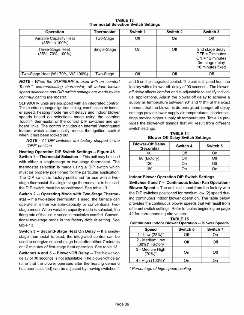
Page 39
TABLE 13Thermostat Selection Switch Settings
Operation Thermostat Switch 1 Switch 2 Switch 3
Variable Capacity Heat (35% to 100%)
Two−Stage Off On Off
Three−Stage Heat (35%, 70%, 100%)
Single−Stage On Off 2nd stage delayOFF = 7 minutesON = 12 minutes3rd stage delay10 minutes fixed
Two−Stage Heat (W1 70%, W2 100%) Two−Stage Off Off Off
NOTE − When the SLP98UHV is used with an icomfort
Touch� communicating thermostat, all indoor blower
speed selections and DIP switch settings are made by the
communicating thermostat.
SLP98UHV units are equipped with an integrated control.This control manages ignition timing, combustion air induc-er speed, heating mode fan off delays and indoor blowerspeeds based on selections made using the icomfortTouch� thermostat or the control DIP switches and on−board links. The control includes an internal Watchguardfeature which automatically resets the ignition controlwhen it has been locked out.
NOTE − All DIP switches are factory shipped in the
�OFF" position.
Heating Operation DIP Switch Settings −− Figure 48
Switch 1 −− Thermostat Selection −− This unit may be used
with either a single−stage or two−stage thermostat. The
thermostat selection is made using a DIP switch which
must be properly positioned for the particular application.
The DIP switch is factory−positioned for use with a two−
stage thermostat. If a single−stage thermostat is to be used,
the DIP switch must be repositioned. See table 13.
Switch 2 −− Operating Mode with Two−Stage Thermo-
stat −− If a two−stage thermostat is used, the furnace can
operate in either variable−capacity or conventional two−
stage mode. When variable−capacity mode is selected, the
firing rate of the unit is varied to maximize comfort. Conven-
tional two−stage mode is the factory default setting. See
table 13.
Switch 3 −− Second−Stage Heat On Delay −− If a single−
stage thermostat is used, the integrated control can be
used to energize second−stage heat after either 7 minutes
or 12 minutes of first−stage heat operation. See table 13.
Switches 4 and 5 −− Blower−Off Delay −− The blower−on
delay of 30 seconds is not adjustable. The blower−off delay
(time that the blower operates after the heating demand
has been satisfied) can be adjusted by moving switches 4
and 5 on the integrated control. The unit is shipped from the
factory with a blower−off delay of 90 seconds. The blower−
off delay affects comfort and is adjustable to satisfy individ-
ual applications. Adjust the blower off delay to achieve a
supply air temperature between 90° and 110°F at the exact
moment that the blower is de−energized. Longer off delay
settings provide lower supply air temperatures; shorter set-
tings provide higher supply air temperatures. Table 14 pro-
vides the blower−off timings that will result from different
switch settings.
TABLE 14Blower−Off Delay Switch Settings
Blower−Off Delay(Seconds)
Switch 4 Switch 5
60 Off On
90 (factory) Off Off
120 On Off
180 On On
Indoor Blower Operation DIP Switch Settings
Switches 6 and 7 −− Continuous Indoor Fan Operation-
Blower Speed −− The unit is shipped from the factory with
the DIP switches positioned for medium low (2) speed dur-
ing continuous indoor blower operation. The table below
provides the continuous blower speeds that will result from
different switch settings. Refer to tables beginning on page
42 for corresponding cfm values.
TABLE 15Continuous Indoor Blower Operation −− Blower Speeds
Speed Switch 6 Switch 7
1 − Low (28%)* Off On
2 − Medium Low(38%)* Factory
Off Off
3 − Medium High(70%)* On Off
4 − High (100%)* On On
* Percentage of high speed cooling
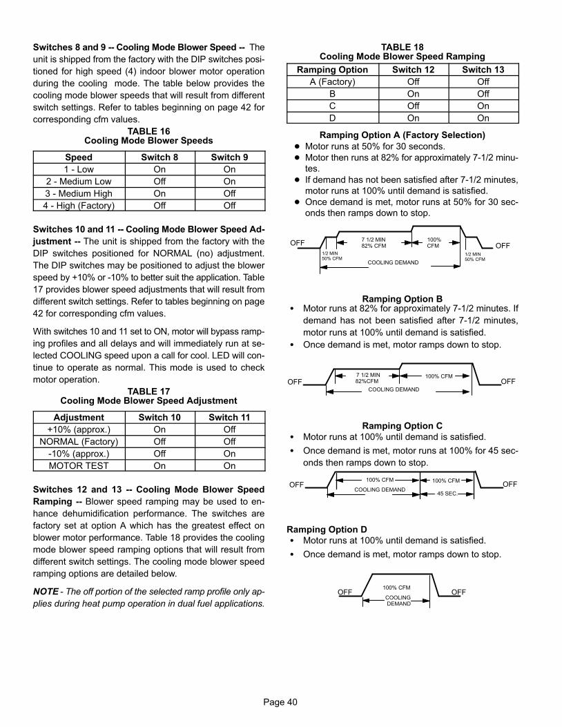
Page 40
Switches 8 and 9 −− Cooling Mode Blower Speed −− The
unit is shipped from the factory with the DIP switches posi-
tioned for high speed (4) indoor blower motor operation
during the cooling mode. The table below provides the
cooling mode blower speeds that will result from different
switch settings. Refer to tables beginning on page 42 for
corresponding cfm values.
TABLE 16Cooling Mode Blower Speeds
Speed Switch 8 Switch 9
1 − Low On On
2 − Medium Low Off On
3 − Medium High On Off
4 − High (Factory) Off Off
Switches 10 and 11 −− Cooling Mode Blower Speed Ad-
justment −− The unit is shipped from the factory with the
DIP switches positioned for NORMAL (no) adjustment.
The DIP switches may be positioned to adjust the blower
speed by +10% or −10% to better suit the application. Table
17 provides blower speed adjustments that will result from
different switch settings. Refer to tables beginning on page
42 for corresponding cfm values.
With switches 10 and 11 set to ON, motor will bypass ramp-
ing profiles and all delays and will immediately run at se-
lected COOLING speed upon a call for cool. LED will con-
tinue to operate as normal. This mode is used to check
motor operation.
TABLE 17Cooling Mode Blower Speed Adjustment
Adjustment Switch 10 Switch 11
+10% (approx.) On Off
NORMAL (Factory) Off Off
−10% (approx.) Off On
MOTOR TEST On On
Switches 12 and 13 −− Cooling Mode Blower Speed
Ramping −− Blower speed ramping may be used to en-
hance dehumidification performance. The switches are
factory set at option A which has the greatest effect on
blower motor performance. Table 18 provides the cooling
mode blower speed ramping options that will result from
different switch settings. The cooling mode blower speed
ramping options are detailed below.
NOTE − The off portion of the selected ramp profile only ap-
plies during heat pump operation in dual fuel applications.
TABLE 18Cooling Mode Blower Speed Ramping
Ramping Option Switch 12 Switch 13
A (Factory) Off Off
B On Off
C Off On
D On On
Ramping Option A (Factory Selection)
� Motor runs at 50% for 30 seconds.
� Motor then runs at 82% for approximately 7−1/2 minu-
tes.
� If demand has not been satisfied after 7−1/2 minutes,
motor runs at 100% until demand is satisfied.
� Once demand is met, motor runs at 50% for 30 sec-
onds then ramps down to stop.
OFFOFF
1/2 MIN50% CFM
COOLING DEMAND
7 1/2 MIN82% CFM
100% CFM
1/2 MIN50% CFM
Ramping Option B� Motor runs at 82% for approximately 7−1/2 minutes. If
demand has not been satisfied after 7−1/2 minutes,
motor runs at 100% until demand is satisfied.
� Once demand is met, motor ramps down to stop.
OFFOFF 82%CFM100% CFM
COOLING DEMAND
7 1/2 MIN
Ramping Option C
� Motor runs at 100% until demand is satisfied.
� Once demand is met, motor runs at 100% for 45 sec-
onds then ramps down to stop.
OFFOFF100% CFM 100% CFM
COOLING DEMAND45 SEC.
Ramping Option D
� Motor runs at 100% until demand is satisfied.
� Once demand is met, motor ramps down to stop.
OFFOFF100% CFM
COOLING DEMAND
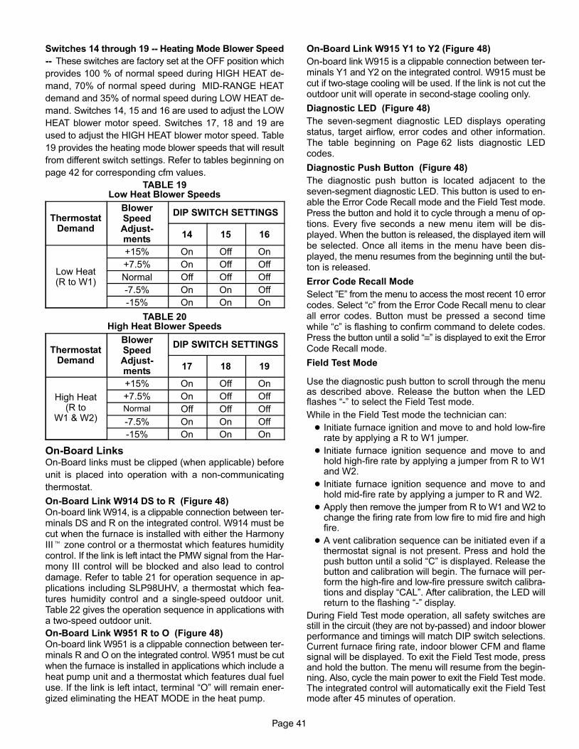
Page 41
Switches 14 through 19 −− Heating Mode Blower Speed
−− These switches are factory set at the OFF position which
provides 100 % of normal speed during HIGH HEAT de-
mand, 70% of normal speed during MID−RANGE HEAT
demand and 35% of normal speed during LOW HEAT de-
mand. Switches 14, 15 and 16 are used to adjust the LOW
HEAT blower motor speed. Switches 17, 18 and 19 are
used to adjust the HIGH HEAT blower motor speed. Table
19 provides the heating mode blower speeds that will result
from different switch settings. Refer to tables beginning on
page 42 for corresponding cfm values.
TABLE 19Low Heat Blower Speeds
ThermostatDemand
BlowerSpeedAdjust-ments
DIP SWITCH SETTINGS
14 15 16
Low Heat(R to W1)
+15% On Off On
+7.5% On Off Off
Normal Off Off Off
−7.5% On On Off
−15% On On On
TABLE 20High Heat Blower Speeds
ThermostatDemand
BlowerSpeedAdjust-ments
DIP SWITCH SETTINGS
17 18 19
High Heat(R to
W1 & W2)
+15% On Off On
+7.5% On Off Off
Normal Off Off Off
−7.5% On On Off
−15% On On On
On−Board LinksOn−Board links must be clipped (when applicable) before
unit is placed into operation with a non−communicating
thermostat.
On−Board Link W914 DS to R (Figure 48)On−board link W914, is a clippable connection between ter-minals DS and R on the integrated control. W914 must becut when the furnace is installed with either the HarmonyIII� zone control or a thermostat which features humiditycontrol. If the link is left intact the PMW signal from the Har-mony III control will be blocked and also lead to controldamage. Refer to table 21 for operation sequence in ap-plications including SLP98UHV, a thermostat which fea-tures humidity control and a single−speed outdoor unit.Table 22 gives the operation sequence in applications witha two−speed outdoor unit.
On−Board Link W951 R to O (Figure 48)On−board link W951 is a clippable connection between ter-minals R and O on the integrated control. W951 must be cutwhen the furnace is installed in applications which include aheat pump unit and a thermostat which features dual fueluse. If the link is left intact, terminal �O" will remain ener-gized eliminating the HEAT MODE in the heat pump.
On−Board Link W915 Y1 to Y2 (Figure 48)
On−board link W915 is a clippable connection between ter-minals Y1 and Y2 on the integrated control. W915 must becut if two−stage cooling will be used. If the link is not cut theoutdoor unit will operate in second−stage cooling only.
Diagnostic LED (Figure 48)
The seven−segment diagnostic LED displays operatingstatus, target airflow, error codes and other information.The table beginning on Page 62 lists diagnostic LEDcodes.
Diagnostic Push Button (Figure 48)
The diagnostic push button is located adjacent to theseven−segment diagnostic LED. This button is used to en-able the Error Code Recall mode and the Field Test mode.Press the button and hold it to cycle through a menu of op-tions. Every five seconds a new menu item will be dis-played. When the button is released, the displayed item willbe selected. Once all items in the menu have been dis-played, the menu resumes from the beginning until the but-ton is released.
Error Code Recall Mode
Select "E" from the menu to access the most recent 10 errorcodes. Select �c" from the Error Code Recall menu to clearall error codes. Button must be pressed a second timewhile �c" is flashing to confirm command to delete codes.Press the button until a solid �≡" is displayed to exit the ErrorCode Recall mode.
Field Test Mode
Use the diagnostic push button to scroll through the menuas described above. Release the button when the LEDflashes �−" to select the Field Test mode.
While in the Field Test mode the technician can:
� Initiate furnace ignition and move to and hold low−firerate by applying a R to W1 jumper.
� Initiate furnace ignition sequence and move to andhold high−fire rate by applying a jumper from R to W1and W2.
� Initiate furnace ignition sequence and move to andhold mid−fire rate by applying a jumper to R and W2.
� Apply then remove the jumper from R to W1 and W2 tochange the firing rate from low fire to mid fire and highfire.
� A vent calibration sequence can be initiated even if athermostat signal is not present. Press and hold thepush button until a solid �C" is displayed. Release thebutton and calibration will begin. The furnace will per-form the high−fire and low−fire pressure switch calibra-tions and display �CAL". After calibration, the LED willreturn to the flashing �−" display.
During Field Test mode operation, all safety switches arestill in the circuit (they are not by−passed) and indoor blowerperformance and timings will match DIP switch selections.Current furnace firing rate, indoor blower CFM and flamesignal will be displayed. To exit the Field Test mode, pressand hold the button. The menu will resume from the begin-ning. Also, cycle the main power to exit the Field Test mode.The integrated control will automatically exit the Field Testmode after 45 minutes of operation.
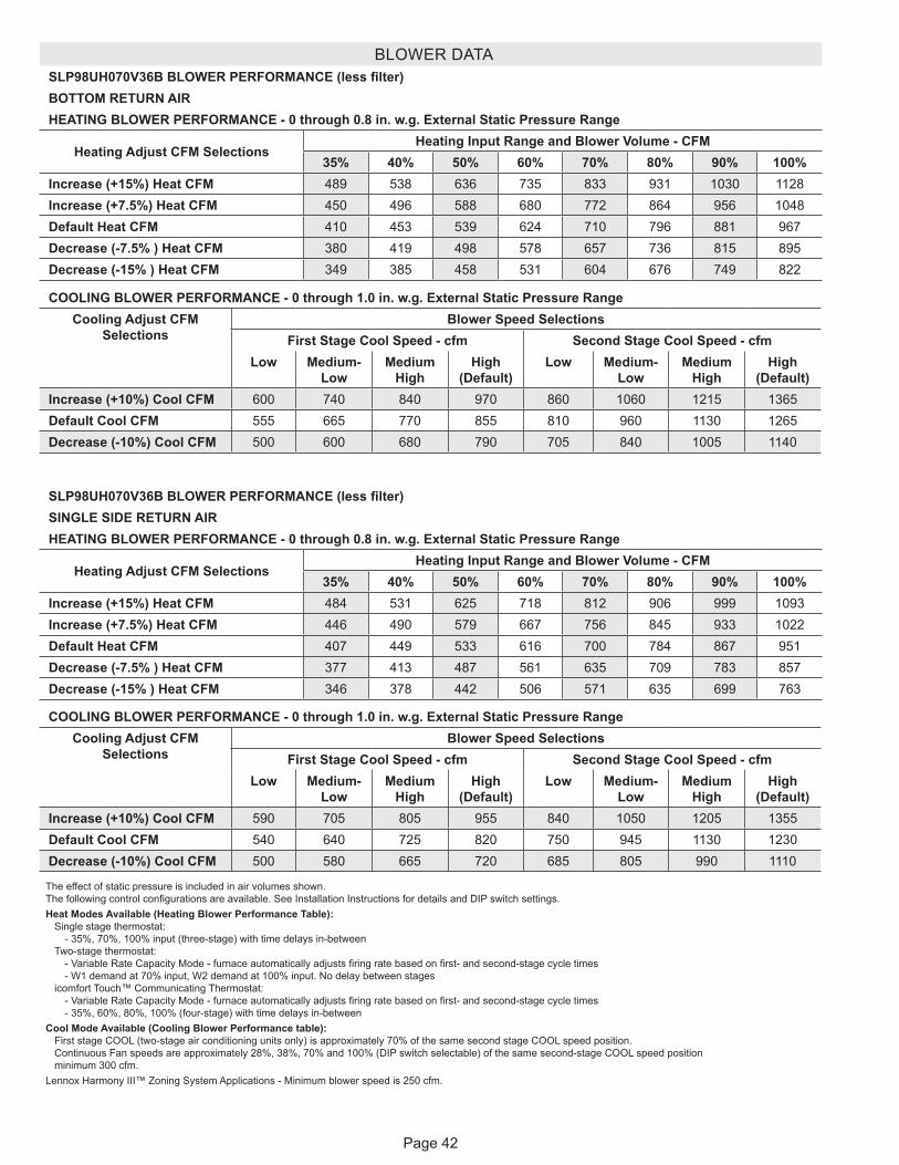
Page 42
BLOWER DATASLP98UH070V36B BLOWER PERFORMANCE (less filter)BOTTOM RETURN AIRHEATING BLOWER PERFORMANCE - 0 through 0.8 in. w.g. External Static Pressure Range
Heating Adjust CFM SelectionsHeating Input Range and Blower Volume - CFM
35% 40% 50% 60% 70% 80% 90% 100%Increase (+15%) Heat CFM 489 538 636 735 833 931 1030 1128Increase (+7.5%) Heat CFM 450 496 588 680 772 864 956 1048Default Heat CFM 410 453 539 624 710 796 881 967Decrease (-7.5% ) Heat CFM 380 419 498 578 657 736 815 895Decrease (-15% ) Heat CFM 349 385 458 531 604 676 749 822
COOLING BLOWER PERFORMANCE - 0 through 1.0 in. w.g. External Static Pressure RangeCooling Adjust CFM
SelectionsBlower Speed Selections
First Stage Cool Speed - cfm Second Stage Cool Speed - cfmLow Medium-
Low Medium
HighHigh
(Default)Low Medium-
Low Medium
HighHigh
(Default)Increase (+10%) Cool CFM 600 740 840 970 860 1060 1215 1365Default Cool CFM 555 665 770 855 810 960 1130 1265Decrease (-10%) Cool CFM 500 600 680 790 705 840 1005 1140
The effect of static pressure is included in air volumes shown. The following control configurations are available. See Installation Instructions for details and DIP switch settings.Heat Modes Available (Heating Blower Performance Table): Single stage thermostat: - 35%, 70%, 100% input (three-stage) with time delays in-between Two-stage thermostat: - Variable Rate Capacity Mode - furnace automatically adjusts firing rate based on first- and second-stage cycle times - W1 demand at 70% input, W2 demand at 100% input. No delay between stages icomfort Touch™ Communicating Thermostat: - Variable Rate Capacity Mode - furnace automatically adjusts firing rate based on first- and second-stage cycle times - 35%, 60%, 80%, 100% (four-stage) with time delays in-betweenCool Mode Available (Cooling Blower Performance table): First stage COOL (two-stage air conditioning units only) is approximately 70% of the same second stage COOL speed position. Continuous Fan speeds are approximately 28%, 38%, 70% and 100% (DIP switch selectable) of the same second-stage COOL speed position minimum 300 cfm.Lennox Harmony III™ Zoning System Applications - Minimum blower speed is 250 cfm.
SLP98UH070V36B BLOWER PERFORMANCE (less filter)SINGLE SIDE RETURN AIRHEATING BLOWER PERFORMANCE - 0 through 0.8 in. w.g. External Static Pressure Range
Heating Adjust CFM SelectionsHeating Input Range and Blower Volume - CFM
35% 40% 50% 60% 70% 80% 90% 100%Increase (+15%) Heat CFM 484 531 625 718 812 906 999 1093Increase (+7.5%) Heat CFM 446 490 579 667 756 845 933 1022Default Heat CFM 407 449 533 616 700 784 867 951Decrease (-7.5% ) Heat CFM 377 413 487 561 635 709 783 857Decrease (-15% ) Heat CFM 346 378 442 506 571 635 699 763
COOLING BLOWER PERFORMANCE - 0 through 1.0 in. w.g. External Static Pressure RangeCooling Adjust CFM
SelectionsBlower Speed Selections
First Stage Cool Speed - cfm Second Stage Cool Speed - cfmLow Medium-
Low Medium
HighHigh
(Default)Low Medium-
Low Medium
HighHigh
(Default)Increase (+10%) Cool CFM 590 705 805 955 840 1050 1205 1355Default Cool CFM 540 640 725 820 750 945 1130 1230Decrease (-10%) Cool CFM 500 580 665 720 685 805 990 1110
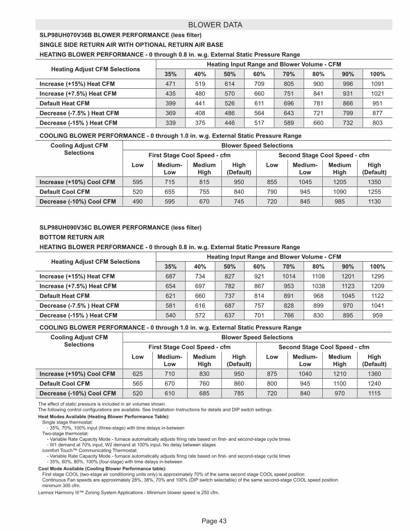
Page 43
BLOWER DATASLP98UH070V36B BLOWER PERFORMANCE (less filter)SINGLE SIDE RETURN AIR WITH OPTIONAL RETURN AIR BASEHEATING BLOWER PERFORMANCE - 0 through 0.8 in. w.g. External Static Pressure Range
Heating Adjust CFM SelectionsHeating Input Range and Blower Volume - CFM
35% 40% 50% 60% 70% 80% 90% 100%Increase (+15%) Heat CFM 471 519 614 709 805 900 996 1091Increase (+7.5%) Heat CFM 435 480 570 660 751 841 931 1021Default Heat CFM 399 441 526 611 696 781 866 951Decrease (-7.5% ) Heat CFM 369 408 486 564 643 721 799 877Decrease (-15% ) Heat CFM 339 375 446 517 589 660 732 803
COOLING BLOWER PERFORMANCE - 0 through 1.0 in. w.g. External Static Pressure RangeCooling Adjust CFM
SelectionsBlower Speed Selections
First Stage Cool Speed - cfm Second Stage Cool Speed - cfmLow Medium-
Low Medium
HighHigh
(Default)Low Medium-
Low Medium
HighHigh
(Default)Increase (+10%) Cool CFM 595 715 815 950 855 1045 1205 1350Default Cool CFM 520 655 755 840 790 945 1090 1255Decrease (-10%) Cool CFM 490 595 670 745 720 845 985 1130
The effect of static pressure is included in air volumes shown. The following control configurations are available. See Installation Instructions for details and DIP switch settings.Heat Modes Available (Heating Blower Performance Table): Single stage thermostat: - 35%, 70%, 100% input (three-stage) with time delays in-between Two-stage thermostat: - Variable Rate Capacity Mode - furnace automatically adjusts firing rate based on first- and second-stage cycle times - W1 demand at 70% input, W2 demand at 100% input. No delay between stages icomfort Touch™ Communicating Thermostat: - Variable Rate Capacity Mode - furnace automatically adjusts firing rate based on first- and second-stage cycle times - 35%, 60%, 80%, 100% (four-stage) with time delays in-betweenCool Mode Available (Cooling Blower Performance table): First stage COOL (two-stage air conditioning units only) is approximately 70% of the same second stage COOL speed position. Continuous Fan speeds are approximately 28%, 38%, 70% and 100% (DIP switch selectable) of the same second-stage COOL speed position minimum 300 cfm.Lennox Harmony III™ Zoning System Applications - Minimum blower speed is 250 cfm.
SLP98UH090V36C BLOWER PERFORMANCE (less filter)BOTTOM RETURN AIRHEATING BLOWER PERFORMANCE - 0 through 0.8 in. w.g. External Static Pressure Range
Heating Adjust CFM SelectionsHeating Input Range and Blower Volume - CFM
35% 40% 50% 60% 70% 80% 90% 100%Increase (+15%) Heat CFM 687 734 827 921 1014 1108 1201 1295Increase (+7.5%) Heat CFM 654 697 782 867 953 1038 1123 1209Default Heat CFM 621 660 737 814 891 968 1045 1122Decrease (-7.5% ) Heat CFM 581 616 687 757 828 899 970 1041Decrease (-15% ) Heat CFM 540 572 637 701 766 830 895 959
COOLING BLOWER PERFORMANCE - 0 through 1.0 in. w.g. External Static Pressure RangeCooling Adjust CFM
SelectionsBlower Speed Selections
First Stage Cool Speed - cfm Second Stage Cool Speed - cfmLow Medium-
Low Medium
HighHigh
(Default)Low Medium-
Low Medium
HighHigh
(Default)Increase (+10%) Cool CFM 625 710 830 950 875 1040 1210 1360Default Cool CFM 565 670 760 860 800 945 1100 1240Decrease (-10%) Cool CFM 520 610 685 785 720 840 970 1115
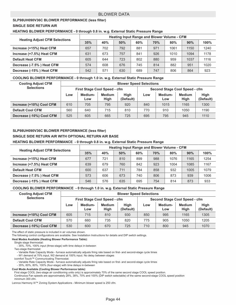
Page 44
BLOWER DATASLP98UH090V36C BLOWER PERFORMANCE (less filter)SINGLE SIDE RETURN AIRHEATING BLOWER PERFORMANCE - 0 through 0.8 in. w.g. External Static Pressure Range
Heating Adjust CFM SelectionsHeating Input Range and Blower Volume - CFM
35% 40% 50% 60% 70% 80% 90% 100%Increase (+15%) Heat CFM 657 702 792 881 971 1061 1150 1240Increase (+7.5%) Heat CFM 631 673 757 841 926 1010 1094 1178Default Heat CFM 605 644 723 802 880 959 1037 1116Decrease (-7.5% ) Heat CFM 574 608 676 745 814 882 951 1020Decrease (-15% ) Heat CFM 542 571 630 689 747 806 864 923
COOLING BLOWER PERFORMANCE - 0 through 1.0 in. w.g. External Static Pressure RangeCooling Adjust CFM
SelectionsBlower Speed Selections
First Stage Cool Speed - cfm Second Stage Cool Speed - cfmLow Medium-
Low Medium
HighHigh
(Default)Low Medium-
Low Medium
HighHigh
(Default)Increase (+10%) Cool CFM 610 705 795 920 840 1015 1165 1300Default Cool CFM 560 640 715 810 770 910 1050 1190Decrease (-10%) Cool CFM 525 605 665 725 695 795 945 1110
The effect of static pressure is included in air volumes shown. The following control configurations are available. See Installation Instructions for details and DIP switch settings.Heat Modes Available (Heating Blower Performance Table): Single stage thermostat: - 35%, 70%, 100% input (three-stage) with time delays in-between Two-stage thermostat: - Variable Rate Capacity Mode - furnace automatically adjusts firing rate based on first- and second-stage cycle times - W1 demand at 70% input, W2 demand at 100% input. No delay between stages icomfort Touch™ Communicating Thermostat: - Variable Rate Capacity Mode - furnace automatically adjusts firing rate based on first- and second-stage cycle times - 35%, 60%, 80%, 100% (four-stage) with time delays in-betweenCool Mode Available (Cooling Blower Performance table): First stage COOL (two-stage air conditioning units only) is approximately 70% of the same second stage COOL speed position. Continuous Fan speeds are approximately 28%, 38%, 70% and 100% (DIP switch selectable) of the same second-stage COOL speed position minimum 300 cfm.Lennox Harmony III™ Zoning System Applications - Minimum blower speed is 250 cfm.
SLP98UH090V36C BLOWER PERFORMANCE (less filter)SINGLE SIDE RETURN AIR WITH OPTIONAL RETURN AIR BASEHEATING BLOWER PERFORMANCE - 0 through 0.8 in. w.g. External Static Pressure Range
Heating Adjust CFM SelectionsHeating Input Range and Blower Volume - CFM
35% 40% 50% 60% 70% 80% 90% 100%Increase (+15%) Heat CFM 677 721 810 899 988 1076 1165 1254Increase (+7.5%) Heat CFM 639 679 760 842 923 1004 1085 1167Default Heat CFM 600 637 711 784 858 932 1005 1079Decrease (-7.5% ) Heat CFM 573 606 673 740 806 873 939 1006Decrease (-15% ) Heat CFM 546 576 635 695 754 814 873 933
COOLING BLOWER PERFORMANCE - 0 through 1.0 in. w.g. External Static Pressure RangeCooling Adjust CFM
SelectionsBlower Speed Selections
First Stage Cool Speed - cfm Second Stage Cool Speed - cfmLow Medium-
Low Medium
HighHigh
(Default)Low Medium-
Low Medium
HighHigh
(Default)Increase (+10%) Cool CFM 605 715 810 930 850 995 1165 1305Default Cool CFM 570 660 735 820 775 905 1050 1205Decrease (-10%) Cool CFM 530 600 670 725 710 800 945 1070
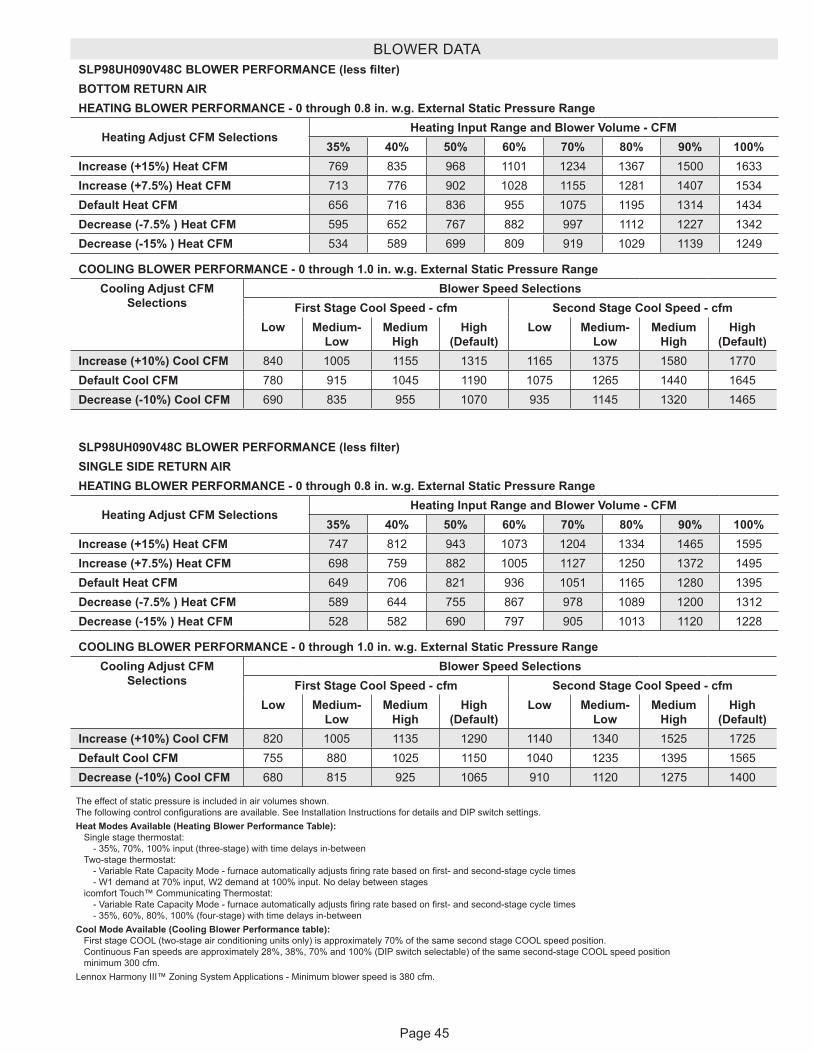
Page 45
BLOWER DATASLP98UH090V48C BLOWER PERFORMANCE (less filter)BOTTOM RETURN AIRHEATING BLOWER PERFORMANCE - 0 through 0.8 in. w.g. External Static Pressure Range
Heating Adjust CFM SelectionsHeating Input Range and Blower Volume - CFM
35% 40% 50% 60% 70% 80% 90% 100%Increase (+15%) Heat CFM 769 835 968 1101 1234 1367 1500 1633Increase (+7.5%) Heat CFM 713 776 902 1028 1155 1281 1407 1534Default Heat CFM 656 716 836 955 1075 1195 1314 1434Decrease (-7.5% ) Heat CFM 595 652 767 882 997 1112 1227 1342Decrease (-15% ) Heat CFM 534 589 699 809 919 1029 1139 1249
COOLING BLOWER PERFORMANCE - 0 through 1.0 in. w.g. External Static Pressure RangeCooling Adjust CFM
SelectionsBlower Speed Selections
First Stage Cool Speed - cfm Second Stage Cool Speed - cfmLow Medium-
Low Medium
HighHigh
(Default)Low Medium-
Low Medium
HighHigh
(Default)Increase (+10%) Cool CFM 840 1005 1155 1315 1165 1375 1580 1770Default Cool CFM 780 915 1045 1190 1075 1265 1440 1645Decrease (-10%) Cool CFM 690 835 955 1070 935 1145 1320 1465
The effect of static pressure is included in air volumes shown. The following control configurations are available. See Installation Instructions for details and DIP switch settings.Heat Modes Available (Heating Blower Performance Table): Single stage thermostat: - 35%, 70%, 100% input (three-stage) with time delays in-between Two-stage thermostat: - Variable Rate Capacity Mode - furnace automatically adjusts firing rate based on first- and second-stage cycle times - W1 demand at 70% input, W2 demand at 100% input. No delay between stages icomfort Touch™ Communicating Thermostat: - Variable Rate Capacity Mode - furnace automatically adjusts firing rate based on first- and second-stage cycle times - 35%, 60%, 80%, 100% (four-stage) with time delays in-betweenCool Mode Available (Cooling Blower Performance table): First stage COOL (two-stage air conditioning units only) is approximately 70% of the same second stage COOL speed position. Continuous Fan speeds are approximately 28%, 38%, 70% and 100% (DIP switch selectable) of the same second-stage COOL speed position minimum 300 cfm.Lennox Harmony III™ Zoning System Applications - Minimum blower speed is 380 cfm.
SLP98UH090V48C BLOWER PERFORMANCE (less filter)SINGLE SIDE RETURN AIRHEATING BLOWER PERFORMANCE - 0 through 0.8 in. w.g. External Static Pressure Range
Heating Adjust CFM SelectionsHeating Input Range and Blower Volume - CFM
35% 40% 50% 60% 70% 80% 90% 100%Increase (+15%) Heat CFM 747 812 943 1073 1204 1334 1465 1595Increase (+7.5%) Heat CFM 698 759 882 1005 1127 1250 1372 1495Default Heat CFM 649 706 821 936 1051 1165 1280 1395Decrease (-7.5% ) Heat CFM 589 644 755 867 978 1089 1200 1312Decrease (-15% ) Heat CFM 528 582 690 797 905 1013 1120 1228
COOLING BLOWER PERFORMANCE - 0 through 1.0 in. w.g. External Static Pressure RangeCooling Adjust CFM
SelectionsBlower Speed Selections
First Stage Cool Speed - cfm Second Stage Cool Speed - cfmLow Medium-
Low Medium
HighHigh
(Default)Low Medium-
Low Medium
HighHigh
(Default)Increase (+10%) Cool CFM 820 1005 1135 1290 1140 1340 1525 1725Default Cool CFM 755 880 1025 1150 1040 1235 1395 1565Decrease (-10%) Cool CFM 680 815 925 1065 910 1120 1275 1400
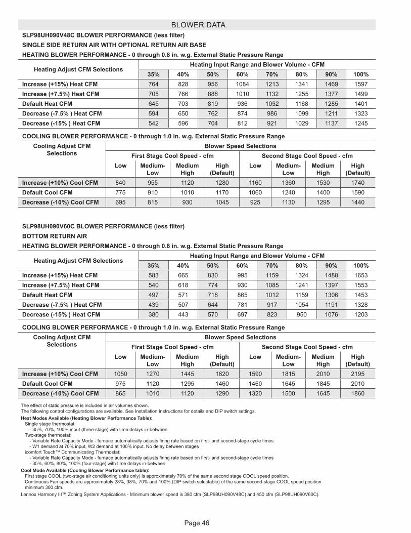
Page 46
BLOWER DATASLP98UH090V48C BLOWER PERFORMANCE (less filter)SINGLE SIDE RETURN AIR WITH OPTIONAL RETURN AIR BASEHEATING BLOWER PERFORMANCE - 0 through 0.8 in. w.g. External Static Pressure Range
Heating Adjust CFM SelectionsHeating Input Range and Blower Volume - CFM
35% 40% 50% 60% 70% 80% 90% 100%Increase (+15%) Heat CFM 764 828 956 1084 1213 1341 1469 1597Increase (+7.5%) Heat CFM 705 766 888 1010 1132 1255 1377 1499Default Heat CFM 645 703 819 936 1052 1168 1285 1401Decrease (-7.5% ) Heat CFM 594 650 762 874 986 1099 1211 1323Decrease (-15% ) Heat CFM 542 596 704 812 921 1029 1137 1245
COOLING BLOWER PERFORMANCE - 0 through 1.0 in. w.g. External Static Pressure RangeCooling Adjust CFM
SelectionsBlower Speed Selections
First Stage Cool Speed - cfm Second Stage Cool Speed - cfmLow Medium-
Low Medium
HighHigh
(Default)Low Medium-
Low Medium
HighHigh
(Default)Increase (+10%) Cool CFM 840 955 1120 1280 1160 1360 1530 1740Default Cool CFM 775 910 1010 1170 1060 1240 1400 1590Decrease (-10%) Cool CFM 695 815 930 1045 925 1130 1295 1440
The effect of static pressure is included in air volumes shown. The following control configurations are available. See Installation Instructions for details and DIP switch settings.Heat Modes Available (Heating Blower Performance Table): Single stage thermostat: - 35%, 70%, 100% input (three-stage) with time delays in-between Two-stage thermostat: - Variable Rate Capacity Mode - furnace automatically adjusts firing rate based on first- and second-stage cycle times - W1 demand at 70% input, W2 demand at 100% input. No delay between stages icomfort Touch™ Communicating Thermostat: - Variable Rate Capacity Mode - furnace automatically adjusts firing rate based on first- and second-stage cycle times - 35%, 60%, 80%, 100% (four-stage) with time delays in-betweenCool Mode Available (Cooling Blower Performance table): First stage COOL (two-stage air conditioning units only) is approximately 70% of the same second stage COOL speed position. Continuous Fan speeds are approximately 28%, 38%, 70% and 100% (DIP switch selectable) of the same second-stage COOL speed position minimum 300 cfm.Lennox Harmony III™ Zoning System Applications - Minimum blower speed is 380 cfm (SLP98UH090V48C) and 450 cfm (SLP98UH090V60C).
SLP98UH090V60C BLOWER PERFORMANCE (less filter)BOTTOM RETURN AIRHEATING BLOWER PERFORMANCE - 0 through 0.8 in. w.g. External Static Pressure Range
Heating Adjust CFM SelectionsHeating Input Range and Blower Volume - CFM
35% 40% 50% 60% 70% 80% 90% 100%Increase (+15%) Heat CFM 583 665 830 995 1159 1324 1488 1653Increase (+7.5%) Heat CFM 540 618 774 930 1085 1241 1397 1553Default Heat CFM 497 571 718 865 1012 1159 1306 1453Decrease (-7.5% ) Heat CFM 439 507 644 781 917 1054 1191 1328Decrease (-15% ) Heat CFM 380 443 570 697 823 950 1076 1203
COOLING BLOWER PERFORMANCE - 0 through 1.0 in. w.g. External Static Pressure RangeCooling Adjust CFM
SelectionsBlower Speed Selections
First Stage Cool Speed - cfm Second Stage Cool Speed - cfmLow Medium-
Low Medium
HighHigh
(Default)Low Medium-
Low Medium
HighHigh
(Default)Increase (+10%) Cool CFM 1050 1270 1445 1620 1590 1815 2010 2195Default Cool CFM 975 1120 1295 1460 1460 1645 1845 2010Decrease (-10%) Cool CFM 865 1010 1120 1290 1320 1500 1645 1860
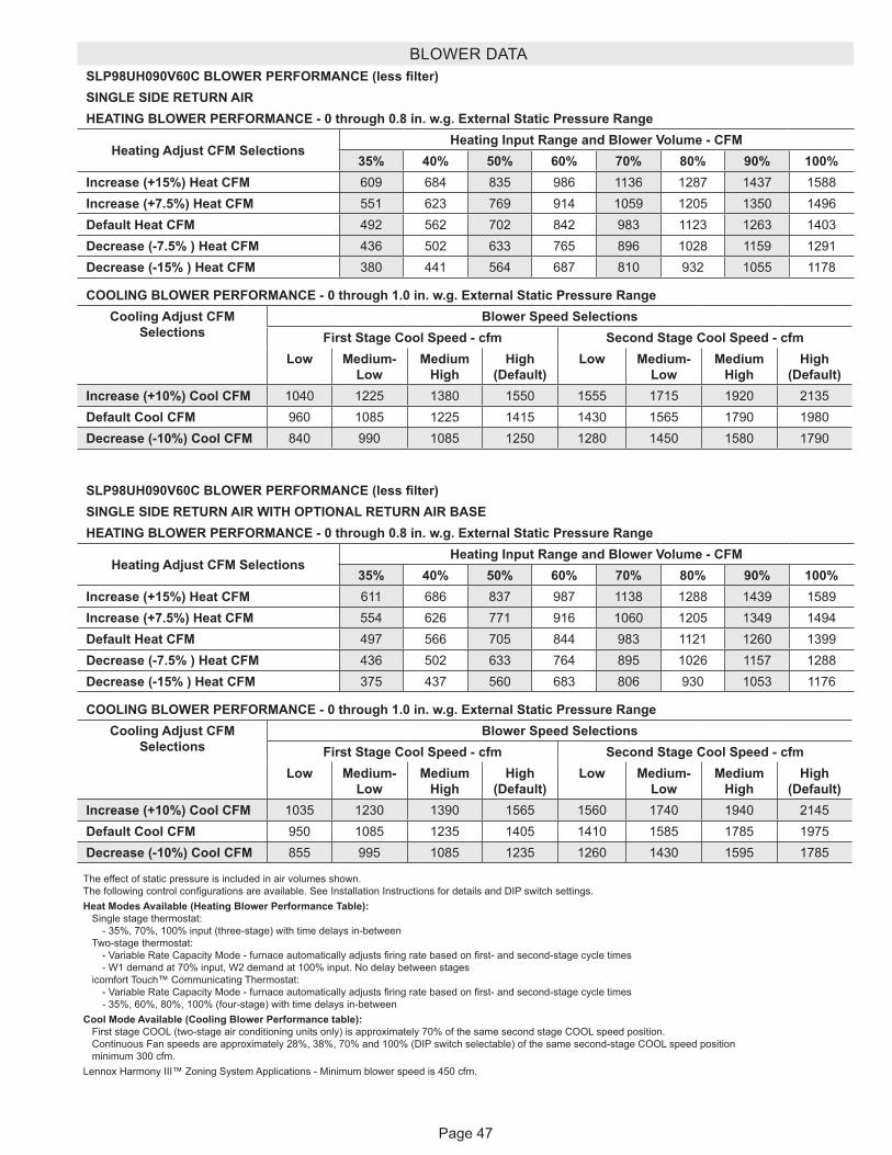
Page 47
BLOWER DATASLP98UH090V60C BLOWER PERFORMANCE (less filter)SINGLE SIDE RETURN AIRHEATING BLOWER PERFORMANCE - 0 through 0.8 in. w.g. External Static Pressure Range
Heating Adjust CFM SelectionsHeating Input Range and Blower Volume - CFM
35% 40% 50% 60% 70% 80% 90% 100%Increase (+15%) Heat CFM 609 684 835 986 1136 1287 1437 1588Increase (+7.5%) Heat CFM 551 623 769 914 1059 1205 1350 1496Default Heat CFM 492 562 702 842 983 1123 1263 1403Decrease (-7.5% ) Heat CFM 436 502 633 765 896 1028 1159 1291Decrease (-15% ) Heat CFM 380 441 564 687 810 932 1055 1178
COOLING BLOWER PERFORMANCE - 0 through 1.0 in. w.g. External Static Pressure RangeCooling Adjust CFM
SelectionsBlower Speed Selections
First Stage Cool Speed - cfm Second Stage Cool Speed - cfmLow Medium-
Low Medium
HighHigh
(Default)Low Medium-
Low Medium
HighHigh
(Default)Increase (+10%) Cool CFM 1040 1225 1380 1550 1555 1715 1920 2135Default Cool CFM 960 1085 1225 1415 1430 1565 1790 1980Decrease (-10%) Cool CFM 840 990 1085 1250 1280 1450 1580 1790
The effect of static pressure is included in air volumes shown. The following control configurations are available. See Installation Instructions for details and DIP switch settings.Heat Modes Available (Heating Blower Performance Table): Single stage thermostat: - 35%, 70%, 100% input (three-stage) with time delays in-between Two-stage thermostat: - Variable Rate Capacity Mode - furnace automatically adjusts firing rate based on first- and second-stage cycle times - W1 demand at 70% input, W2 demand at 100% input. No delay between stages icomfort Touch™ Communicating Thermostat: - Variable Rate Capacity Mode - furnace automatically adjusts firing rate based on first- and second-stage cycle times - 35%, 60%, 80%, 100% (four-stage) with time delays in-betweenCool Mode Available (Cooling Blower Performance table): First stage COOL (two-stage air conditioning units only) is approximately 70% of the same second stage COOL speed position. Continuous Fan speeds are approximately 28%, 38%, 70% and 100% (DIP switch selectable) of the same second-stage COOL speed position minimum 300 cfm.Lennox Harmony III™ Zoning System Applications - Minimum blower speed is 450 cfm.
SLP98UH090V60C BLOWER PERFORMANCE (less filter)SINGLE SIDE RETURN AIR WITH OPTIONAL RETURN AIR BASEHEATING BLOWER PERFORMANCE - 0 through 0.8 in. w.g. External Static Pressure Range
Heating Adjust CFM SelectionsHeating Input Range and Blower Volume - CFM
35% 40% 50% 60% 70% 80% 90% 100%Increase (+15%) Heat CFM 611 686 837 987 1138 1288 1439 1589Increase (+7.5%) Heat CFM 554 626 771 916 1060 1205 1349 1494Default Heat CFM 497 566 705 844 983 1121 1260 1399Decrease (-7.5% ) Heat CFM 436 502 633 764 895 1026 1157 1288Decrease (-15% ) Heat CFM 375 437 560 683 806 930 1053 1176
COOLING BLOWER PERFORMANCE - 0 through 1.0 in. w.g. External Static Pressure RangeCooling Adjust CFM
SelectionsBlower Speed Selections
First Stage Cool Speed - cfm Second Stage Cool Speed - cfmLow Medium-
Low Medium
HighHigh
(Default)Low Medium-
Low Medium
HighHigh
(Default)Increase (+10%) Cool CFM 1035 1230 1390 1565 1560 1740 1940 2145Default Cool CFM 950 1085 1235 1405 1410 1585 1785 1975Decrease (-10%) Cool CFM 855 995 1085 1235 1260 1430 1595 1785
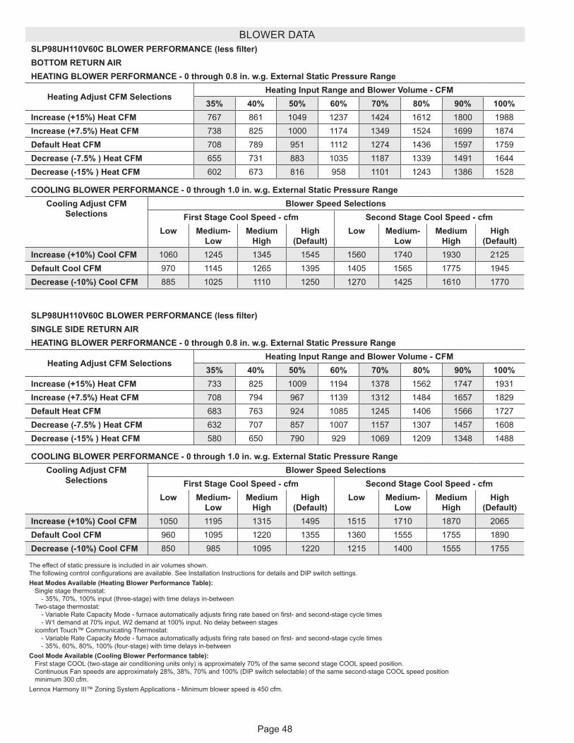
Page 48
BLOWER DATASLP98UH110V60C BLOWER PERFORMANCE (less filter)BOTTOM RETURN AIRHEATING BLOWER PERFORMANCE - 0 through 0.8 in. w.g. External Static Pressure Range
Heating Adjust CFM SelectionsHeating Input Range and Blower Volume - CFM
35% 40% 50% 60% 70% 80% 90% 100%Increase (+15%) Heat CFM 767 861 1049 1237 1424 1612 1800 1988Increase (+7.5%) Heat CFM 738 825 1000 1174 1349 1524 1699 1874Default Heat CFM 708 789 951 1112 1274 1436 1597 1759Decrease (-7.5% ) Heat CFM 655 731 883 1035 1187 1339 1491 1644Decrease (-15% ) Heat CFM 602 673 816 958 1101 1243 1386 1528
COOLING BLOWER PERFORMANCE - 0 through 1.0 in. w.g. External Static Pressure RangeCooling Adjust CFM
SelectionsBlower Speed Selections
First Stage Cool Speed - cfm Second Stage Cool Speed - cfmLow Medium-
Low Medium
HighHigh
(Default)Low Medium-
Low Medium
HighHigh
(Default)Increase (+10%) Cool CFM 1060 1245 1345 1545 1560 1740 1930 2125Default Cool CFM 970 1145 1265 1395 1405 1565 1775 1945Decrease (-10%) Cool CFM 885 1025 1110 1250 1270 1425 1610 1770
The effect of static pressure is included in air volumes shown. The following control configurations are available. See Installation Instructions for details and DIP switch settings.Heat Modes Available (Heating Blower Performance Table): Single stage thermostat: - 35%, 70%, 100% input (three-stage) with time delays in-between Two-stage thermostat: - Variable Rate Capacity Mode - furnace automatically adjusts firing rate based on first- and second-stage cycle times - W1 demand at 70% input, W2 demand at 100% input. No delay between stages icomfort Touch™ Communicating Thermostat: - Variable Rate Capacity Mode - furnace automatically adjusts firing rate based on first- and second-stage cycle times - 35%, 60%, 80%, 100% (four-stage) with time delays in-betweenCool Mode Available (Cooling Blower Performance table): First stage COOL (two-stage air conditioning units only) is approximately 70% of the same second stage COOL speed position. Continuous Fan speeds are approximately 28%, 38%, 70% and 100% (DIP switch selectable) of the same second-stage COOL speed position minimum 300 cfm.Lennox Harmony III™ Zoning System Applications - Minimum blower speed is 450 cfm.
SLP98UH110V60C BLOWER PERFORMANCE (less filter)SINGLE SIDE RETURN AIRHEATING BLOWER PERFORMANCE - 0 through 0.8 in. w.g. External Static Pressure Range
Heating Adjust CFM SelectionsHeating Input Range and Blower Volume - CFM
35% 40% 50% 60% 70% 80% 90% 100%Increase (+15%) Heat CFM 733 825 1009 1194 1378 1562 1747 1931Increase (+7.5%) Heat CFM 708 794 967 1139 1312 1484 1657 1829Default Heat CFM 683 763 924 1085 1245 1406 1566 1727Decrease (-7.5% ) Heat CFM 632 707 857 1007 1157 1307 1457 1608Decrease (-15% ) Heat CFM 580 650 790 929 1069 1209 1348 1488
COOLING BLOWER PERFORMANCE - 0 through 1.0 in. w.g. External Static Pressure RangeCooling Adjust CFM
SelectionsBlower Speed Selections
First Stage Cool Speed - cfm Second Stage Cool Speed - cfmLow Medium-
Low Medium
HighHigh
(Default)Low Medium-
Low Medium
HighHigh
(Default)Increase (+10%) Cool CFM 1050 1195 1315 1495 1515 1710 1870 2065Default Cool CFM 960 1095 1220 1355 1360 1555 1755 1890Decrease (-10%) Cool CFM 850 985 1095 1220 1215 1400 1555 1755
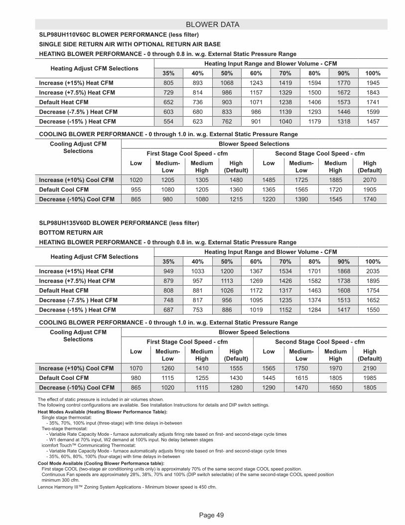
Page 49
BLOWER DATASLP98UH110V60C BLOWER PERFORMANCE (less filter)SINGLE SIDE RETURN AIR WITH OPTIONAL RETURN AIR BASEHEATING BLOWER PERFORMANCE - 0 through 0.8 in. w.g. External Static Pressure Range
Heating Adjust CFM SelectionsHeating Input Range and Blower Volume - CFM
35% 40% 50% 60% 70% 80% 90% 100%Increase (+15%) Heat CFM 805 893 1068 1243 1419 1594 1770 1945Increase (+7.5%) Heat CFM 729 814 986 1157 1329 1500 1672 1843Default Heat CFM 652 736 903 1071 1238 1406 1573 1741Decrease (-7.5% ) Heat CFM 603 680 833 986 1139 1293 1446 1599Decrease (-15% ) Heat CFM 554 623 762 901 1040 1179 1318 1457
COOLING BLOWER PERFORMANCE - 0 through 1.0 in. w.g. External Static Pressure RangeCooling Adjust CFM
SelectionsBlower Speed Selections
First Stage Cool Speed - cfm Second Stage Cool Speed - cfmLow Medium-
Low Medium
HighHigh
(Default)Low Medium-
Low Medium
HighHigh
(Default)Increase (+10%) Cool CFM 1020 1205 1305 1480 1485 1725 1885 2070Default Cool CFM 955 1080 1205 1360 1365 1565 1720 1905Decrease (-10%) Cool CFM 865 980 1080 1215 1220 1390 1545 1740
The effect of static pressure is included in air volumes shown. The following control configurations are available. See Installation Instructions for details and DIP switch settings.Heat Modes Available (Heating Blower Performance Table): Single stage thermostat: - 35%, 70%, 100% input (three-stage) with time delays in-between Two-stage thermostat: - Variable Rate Capacity Mode - furnace automatically adjusts firing rate based on first- and second-stage cycle times - W1 demand at 70% input, W2 demand at 100% input. No delay between stages icomfort Touch™ Communicating Thermostat: - Variable Rate Capacity Mode - furnace automatically adjusts firing rate based on first- and second-stage cycle times - 35%, 60%, 80%, 100% (four-stage) with time delays in-betweenCool Mode Available (Cooling Blower Performance table): First stage COOL (two-stage air conditioning units only) is approximately 70% of the same second stage COOL speed position. Continuous Fan speeds are approximately 28%, 38%, 70% and 100% (DIP switch selectable) of the same second-stage COOL speed position minimum 300 cfm.Lennox Harmony III™ Zoning System Applications - Minimum blower speed is 450 cfm.
SLP98UH135V60D BLOWER PERFORMANCE (less filter)BOTTOM RETURN AIRHEATING BLOWER PERFORMANCE - 0 through 0.8 in. w.g. External Static Pressure Range
Heating Adjust CFM SelectionsHeating Input Range and Blower Volume - CFM
35% 40% 50% 60% 70% 80% 90% 100%Increase (+15%) Heat CFM 949 1033 1200 1367 1534 1701 1868 2035Increase (+7.5%) Heat CFM 879 957 1113 1269 1426 1582 1738 1895Default Heat CFM 808 881 1026 1172 1317 1463 1608 1754Decrease (-7.5% ) Heat CFM 748 817 956 1095 1235 1374 1513 1652Decrease (-15% ) Heat CFM 687 753 886 1019 1152 1284 1417 1550
COOLING BLOWER PERFORMANCE - 0 through 1.0 in. w.g. External Static Pressure RangeCooling Adjust CFM
SelectionsBlower Speed Selections
First Stage Cool Speed - cfm Second Stage Cool Speed - cfmLow Medium-
Low Medium
HighHigh
(Default)Low Medium-
Low Medium
HighHigh
(Default)Increase (+10%) Cool CFM 1070 1260 1410 1555 1565 1750 1970 2190Default Cool CFM 980 1115 1255 1430 1445 1615 1805 1985Decrease (-10%) Cool CFM 865 1020 1115 1280 1290 1470 1650 1805
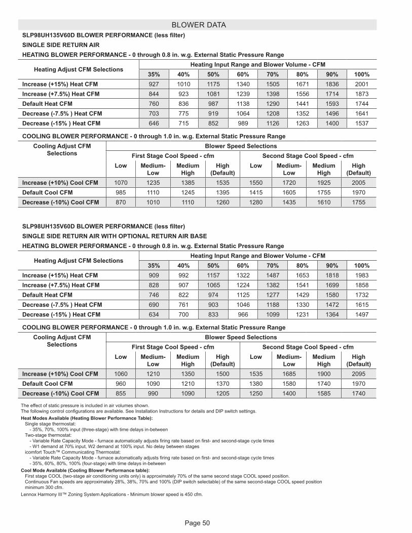
Page 50
BLOWER DATASLP98UH135V60D BLOWER PERFORMANCE (less filter)SINGLE SIDE RETURN AIRHEATING BLOWER PERFORMANCE - 0 through 0.8 in. w.g. External Static Pressure Range
Heating Adjust CFM SelectionsHeating Input Range and Blower Volume - CFM
35% 40% 50% 60% 70% 80% 90% 100%Increase (+15%) Heat CFM 927 1010 1175 1340 1505 1671 1836 2001Increase (+7.5%) Heat CFM 844 923 1081 1239 1398 1556 1714 1873Default Heat CFM 760 836 987 1138 1290 1441 1593 1744Decrease (-7.5% ) Heat CFM 703 775 919 1064 1208 1352 1496 1641Decrease (-15% ) Heat CFM 646 715 852 989 1126 1263 1400 1537
COOLING BLOWER PERFORMANCE - 0 through 1.0 in. w.g. External Static Pressure RangeCooling Adjust CFM
SelectionsBlower Speed Selections
First Stage Cool Speed - cfm Second Stage Cool Speed - cfmLow Medium-
Low Medium
HighHigh
(Default)Low Medium-
Low Medium
HighHigh
(Default)Increase (+10%) Cool CFM 1070 1235 1385 1535 1550 1720 1925 2005Default Cool CFM 985 1110 1245 1395 1415 1605 1755 1970Decrease (-10%) Cool CFM 870 1010 1110 1260 1280 1435 1610 1755
The effect of static pressure is included in air volumes shown. The following control configurations are available. See Installation Instructions for details and DIP switch settings.Heat Modes Available (Heating Blower Performance Table): Single stage thermostat: - 35%, 70%, 100% input (three-stage) with time delays in-between Two-stage thermostat: - Variable Rate Capacity Mode - furnace automatically adjusts firing rate based on first- and second-stage cycle times - W1 demand at 70% input, W2 demand at 100% input. No delay between stages icomfort Touch™ Communicating Thermostat: - Variable Rate Capacity Mode - furnace automatically adjusts firing rate based on first- and second-stage cycle times - 35%, 60%, 80%, 100% (four-stage) with time delays in-betweenCool Mode Available (Cooling Blower Performance table): First stage COOL (two-stage air conditioning units only) is approximately 70% of the same second stage COOL speed position. Continuous Fan speeds are approximately 28%, 38%, 70% and 100% (DIP switch selectable) of the same second-stage COOL speed position minimum 300 cfm.Lennox Harmony III™ Zoning System Applications - Minimum blower speed is 450 cfm.
SLP98UH135V60D BLOWER PERFORMANCE (less filter)SINGLE SIDE RETURN AIR WITH OPTIONAL RETURN AIR BASEHEATING BLOWER PERFORMANCE - 0 through 0.8 in. w.g. External Static Pressure Range
Heating Adjust CFM SelectionsHeating Input Range and Blower Volume - CFM
35% 40% 50% 60% 70% 80% 90% 100%Increase (+15%) Heat CFM 909 992 1157 1322 1487 1653 1818 1983Increase (+7.5%) Heat CFM 828 907 1065 1224 1382 1541 1699 1858Default Heat CFM 746 822 974 1125 1277 1429 1580 1732Decrease (-7.5% ) Heat CFM 690 761 903 1046 1188 1330 1472 1615Decrease (-15% ) Heat CFM 634 700 833 966 1099 1231 1364 1497
COOLING BLOWER PERFORMANCE - 0 through 1.0 in. w.g. External Static Pressure RangeCooling Adjust CFM
SelectionsBlower Speed Selections
First Stage Cool Speed - cfm Second Stage Cool Speed - cfmLow Medium-
Low Medium
HighHigh
(Default)Low Medium-
Low Medium
HighHigh
(Default)Increase (+10%) Cool CFM 1060 1210 1350 1500 1535 1685 1900 2095Default Cool CFM 960 1090 1210 1370 1380 1580 1740 1970Decrease (-10%) Cool CFM 855 990 1090 1205 1250 1400 1585 1740
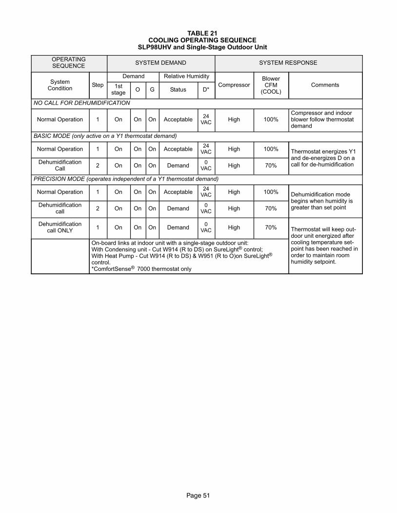
Page 51
TABLE 21COOLING OPERATING SEQUENCE
SLP98UHV and Single−Stage Outdoor Unit
OPERATINGSEQUENCE
SYSTEM DEMAND SYSTEM RESPONSE
SystemCondition
Step
Demand Relative Humidity
CompressorBlowerCFM
(COOL)Comments1st
stageO G Status D*
NO CALL FOR DEHUMIDIFICATION
Normal Operation 1 On On On Acceptable24
VACHigh 100%
Compressor and indoorblower follow thermostatdemand
BASIC MODE (only active on a Y1 thermostat demand)
Normal Operation 1 On On On Acceptable24
VACHigh 100% Thermostat energizes Y1
and de−energizes D on acall for de−humidificationDehumidification
Call2 On On On Demand
0VAC
High 70%
PRECISION MODE (operates independent of a Y1 thermostat demand)
Normal Operation 1 On On On Acceptable24
VACHigh 100% Dehumidification mode
begins when humidity isgreater than set pointDehumidification
call2 On On On Demand
0VAC
High 70%
Dehumidificationcall ONLY
1 On On On Demand0
VACHigh 70% Thermostat will keep out-
door unit energized aftercooling temperature set-point has been reached inorder to maintain roomhumidity setpoint.
On−board links at indoor unit with a single−stage outdoor unit:With Condensing unit − Cut W914 (R to DS) on SureLight® control;With Heat Pump − Cut W914 (R to DS) & W951 (R to O)on SureLight® control.*ComfortSense® 7000 thermostat only
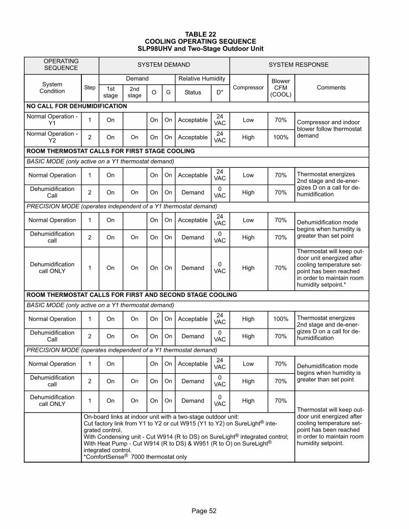
Page 52
TABLE 22COOLING OPERATING SEQUENCE
SLP98UHV and Two−Stage Outdoor Unit
OPERATINGSEQUENCE
SYSTEM DEMAND SYSTEM RESPONSE
SystemCondition
Step
Demand Relative Humidity
CompressorBlowerCFM
(COOL)Comments1st
stage2nd
stageO G Status D*
NO CALL FOR DEHUMIDIFICATION
Normal Operation −Y1
1 On On On Acceptable24
VACLow 70% Compressor and indoor
blower follow thermostatdemandNormal Operation −
Y22 On On On On Acceptable
24VAC
High 100%
ROOM THERMOSTAT CALLS FOR FIRST STAGE COOLING
BASIC MODE (only active on a Y1 thermostat demand)
Normal Operation 1 On On On Acceptable24
VACLow 70% Thermostat energizes
2nd stage and de−ener-gizes D on a call for de−humidification
DehumidificationCall
2 On On On On Demand0
VACHigh 70%
PRECISION MODE (operates independent of a Y1 thermostat demand)
Normal Operation 1 On On On Acceptable24
VACLow 70% Dehumidification mode
begins when humidity isgreater than set pointDehumidification
call2 On On On On Demand
0VAC
High 70%
Dehumidificationcall ONLY
1 On On On On Demand0
VACHigh 70%
Thermostat will keep out-door unit energized aftercooling temperature set-point has been reachedin order to maintain roomhumidity setpoint.*
ROOM THERMOSTAT CALLS FOR FIRST AND SECOND STAGE COOLING
BASIC MODE (only active on a Y1 thermostat demand)
Normal Operation 1 On On On On Acceptable24
VACHigh 100% Thermostat energizes
2nd stage and de−ener-gizes D on a call for de−humidification
DehumidificationCall
2 On On On On Demand0
VACHigh 70%
PRECISION MODE (operates independent of a Y1 thermostat demand)
Normal Operation 1 On On On Acceptable24
VACLow 70% Dehumidification mode
begins when humidity isgreater than set pointDehumidification
call2 On On On On Demand
0VAC
High 70%
Dehumidificationcall ONLY
1 On On On On Demand0
VACHigh 70%
Thermostat will keep out-door unit energized aftercooling temperature set-point has been reachedin order to maintain roomhumidity setpoint.
On−board links at indoor unit with a two−stage outdoor unit:Cut factory link from Y1 to Y2 or cut W915 (Y1 to Y2) on SureLight® inte-grated control.With Condensing unit − Cut W914 (R to DS) on SureLight® integrated control;With Heat Pump − Cut W914 (R to DS) & W951 (R to O) on SureLight® integrated control.*ComfortSense® 7000 thermostat only
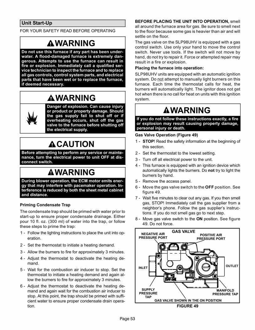
Page 53
Unit Start−Up
FOR YOUR SAFETY READ BEFORE OPERATING
WARNINGDo not use this furnace if any part has been under-water. A flood−damaged furnace is extremely dan-gerous. Attempts to use the furnace can result infire or explosion. Immediately call a qualified ser-vice technician to inspect the furnace and to replaceall gas controls, control system parts, and electricalparts that have been wet or to replace the furnace,if deemed necessary.
WARNINGDanger of explosion. Can cause injuryor product or property damage. Shouldthe gas supply fail to shut off or ifoverheating occurs, shut off the gasvalve to the furnace before shutting offthe electrical supply.
CAUTIONBefore attempting to perform any service or mainte-nance, turn the electrical power to unit OFF at dis-connect switch.
WARNINGDuring blower operation, the ECM motor emits ener-gy that may interfere with pacemaker operation. In-terference is reduced by both the sheet metal cabinetand distance.
Priming Condensate Trap
The condensate trap should be primed with water prior to
start−up to ensure proper condensate drainage. Either
pour 10 fl. oz. (300 ml) of water into the trap, or follow
these steps to prime the trap:
1 − Follow the lighting instructions to place the unit into op-
eration.
2 − Set the thermostat to initiate a heating demand.
3 − Allow the burners to fire for approximately 3 minutes.
4 − Adjust the thermostat to deactivate the heating de-
mand.
5 − Wait for the combustion air inducer to stop. Set the
thermostat to initiate a heating demand and again al-
low the burners to fire for approximately 3 minutes.
6 − Adjust the thermostat to deactivate the heating de-
mand and again wait for the combustion air inducer to
stop. At this point, the trap should be primed with suffi-
cient water to ensure proper condensate drain opera-
tion.
BEFORE PLACING THE UNIT INTO OPERATION, smell
all around the furnace area for gas. Be sure to smell next
to the floor because some gas is heavier than air and will
settle on the floor.
The gas valve on the SLP98UHV is equipped with a gas
control switch. Use only your hand to move the control
switch. Never use tools. If the switch will not move by
hand, do not try to repair it. Force or attempted repair may
result in a fire or explosion.
Placing the furnace into operation:
SLP98UHV units are equipped with an automatic ignition
system. Do not attempt to manually light burners on this
furnace. Each time the thermostat calls for heat, the
burners will automatically light. The ignitor does not get
hot when there is no call for heat on units with this ignition
system.
WARNINGIf you do not follow these instructions exactly, a fireor explosion may result causing property damage,personal injury or death.
Gas Valve Operation (Figure 49)
1 − STOP! Read the safety information at the beginning of
this section.
2 − Set the thermostat to the lowest setting.
3 − Turn off all electrical power to the unit.
4 − This furnace is equipped with an ignition device which
automatically lights the burners. Do not try to light the
burners by hand.
5 − Remove the access panel.
6 − Move the gas valve switch to the OFF position. See
figure 49.
7 − Wait five minutes to clear out any gas. If you then smell
gas, STOP! Immediately call the gas supplier from a
neighbor’s phone. Follow the gas supplier’s instruc-
tions. If you do not smell gas go to next step.
8 − Move gas valve switch to the ON position. See figure
49. Do not force.
GAS VALVENEGATIVE AIR
PRESSURE PORTPOSITIVE AIR
PRESSURE PORT
MANIFOLDPRESSURE TAP
INLETOUTLET
SUPPLYPRESSURE
TAPGAS VALVE SHOWN IN THE ON POSITION
FIGURE 49
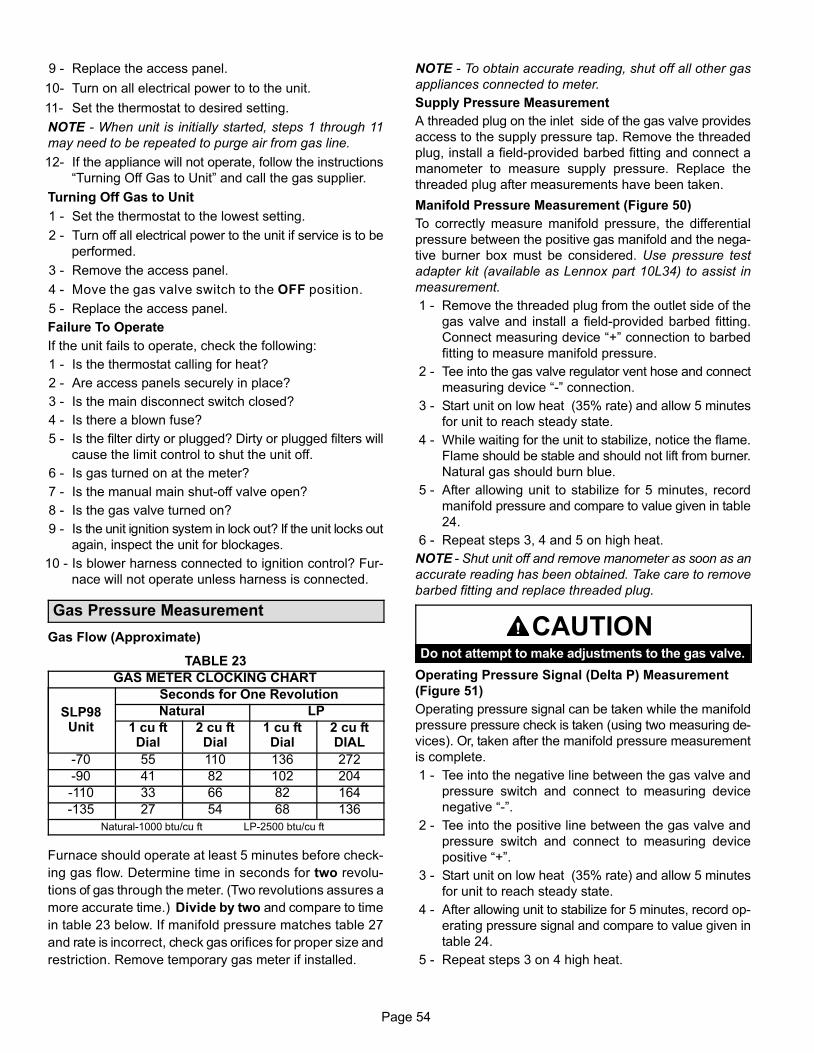
Page 54
9 − Replace the access panel.
10− Turn on all electrical power to to the unit.
11− Set the thermostat to desired setting.
NOTE − When unit is initially started, steps 1 through 11
may need to be repeated to purge air from gas line.
12− If the appliance will not operate, follow the instructions
�Turning Off Gas to Unit" and call the gas supplier.
Turning Off Gas to Unit
1 − Set the thermostat to the lowest setting.
2 − Turn off all electrical power to the unit if service is to be
performed.
3 − Remove the access panel.
4 − Move the gas valve switch to the OFF position.
5 − Replace the access panel.
Failure To Operate
If the unit fails to operate, check the following:
1 − Is the thermostat calling for heat?
2 − Are access panels securely in place?
3 − Is the main disconnect switch closed?
4 − Is there a blown fuse?
5 − Is the filter dirty or plugged? Dirty or plugged filters will
cause the limit control to shut the unit off.
6 − Is gas turned on at the meter?
7 − Is the manual main shut-off valve open?
8 − Is the gas valve turned on?
9 − Is the unit ignition system in lock out? If the unit locks out
again, inspect the unit for blockages.
10 − Is blower harness connected to ignition control? Fur-
nace will not operate unless harness is connected.
Gas Pressure Measurement
Gas Flow (Approximate)
TABLE 23
GAS METER CLOCKING CHART
SLP98Unit
Seconds for One Revolution
Natural LP
1 cu ftDial
2 cu ftDial
1 cu ftDial
2 cu ftDIAL
−70 55 110 136 272
−90 41 82 102 204
−110 33 66 82 164
−135 27 54 68 136
Natural−1000 btu/cu ft LP−2500 btu/cu ft
Furnace should operate at least 5 minutes before check-
ing gas flow. Determine time in seconds for two revolu-
tions of gas through the meter. (Two revolutions assures a
more accurate time.) Divide by two and compare to time
in table 23 below. If manifold pressure matches table 27
and rate is incorrect, check gas orifices for proper size and
restriction. Remove temporary gas meter if installed.
NOTE − To obtain accurate reading, shut off all other gas
appliances connected to meter.
Supply Pressure Measurement
A threaded plug on the inlet side of the gas valve provides
access to the supply pressure tap. Remove the threaded
plug, install a field−provided barbed fitting and connect a
manometer to measure supply pressure. Replace the
threaded plug after measurements have been taken.
Manifold Pressure Measurement (Figure 50)
To correctly measure manifold pressure, the differential
pressure between the positive gas manifold and the nega-
tive burner box must be considered. Use pressure test
adapter kit (available as Lennox part 10L34) to assist in
measurement.
1 − Remove the threaded plug from the outlet side of the
gas valve and install a field−provided barbed fitting.
Connect measuring device �+" connection to barbed
fitting to measure manifold pressure.
2 − Tee into the gas valve regulator vent hose and connect
measuring device �−" connection.
3 − Start unit on low heat (35% rate) and allow 5 minutes
for unit to reach steady state.
4 − While waiting for the unit to stabilize, notice the flame.
Flame should be stable and should not lift from burner.
Natural gas should burn blue.
5 − After allowing unit to stabilize for 5 minutes, record
manifold pressure and compare to value given in table
24.
6 − Repeat steps 3, 4 and 5 on high heat.
NOTE − Shut unit off and remove manometer as soon as an
accurate reading has been obtained. Take care to remove
barbed fitting and replace threaded plug.
CAUTIONDo not attempt to make adjustments to the gas valve.
Operating Pressure Signal (Delta P) Measurement
(Figure 51)
Operating pressure signal can be taken while the manifold
pressure pressure check is taken (using two measuring de-
vices). Or, taken after the manifold pressure measurement
is complete.
1 − Tee into the negative line between the gas valve and
pressure switch and connect to measuring device
negative �−".
2 − Tee into the positive line between the gas valve and
pressure switch and connect to measuring device
positive �+".
3 − Start unit on low heat (35% rate) and allow 5 minutes
for unit to reach steady state.
4 − After allowing unit to stabilize for 5 minutes, record op-
erating pressure signal and compare to value given in
table 24.
5 − Repeat steps 3 on 4 high heat.
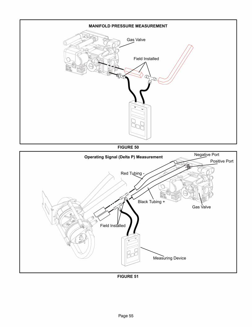
Page 55
FIGURE 50
Field Installed
Gas Valve
MANIFOLD PRESSURE MEASUREMENT
FIGURE 51
Negative Port
Positive Port
Gas Valve
Measuring Device
Field Installed
Operating Signal (Delta P) Measurement
Black Tubing +
Red Tubing −
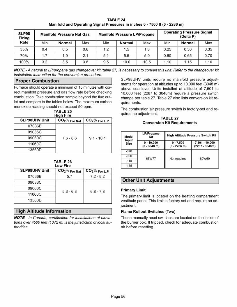
Page 56
TABLE 24Manifold and Operating Signal Pressures in inches 0 − 7500 ft (0 − 2286 m)
SLP98FiringRate
Manifold Pressure Nat Gas Manifold Pressure LP/PropaneOperating Pressure Signal
(Delta P)
Min Normal Max Min Normal Max Min Normal Max
35% 0.4 0.5 0.6 1.2 1.5 1.8 0.25 0.30 0.35
70% 1.7 1.9 2.1 5.1 5.5 5.9 0.60 0.65 0.70
100% 3.2 3.5 3.8 9.5 10.0 10.5 1.10 1.15 1.10
NOTE − A natural to LP/propane gas changeover kit (table 27) is necessary to convert this unit. Refer to the changeover kit
installation instruction for the conversion procedure.
Proper Combustion
Furnace should operate a minimum of 15 minutes with cor-
rect manifold pressure and gas flow rate before checking
combustion. Take combustion sample beyond the flue out-
let and compare to the tables below. The maximum carbon
monoxide reading should not exceed 50 ppm.
TABLE 25High Fire
SLP98UHV Unit CO2% For Nat CO2% For L.P.
07036B
7.6 − 8.6 9.1 − 10.1
09036C
09060C
11060C
13560D
TABLE 26Low Fire
SLP98UHV Unit CO2% For Nat CO2% For L.P.
07036B 5.7 7.2 − 8.2
09036C
5.3 − 6.3 6.8 − 7.809060C
11060C
13560D
High Altitude Information
NOTE − In Canada, certification for installations at eleva-
tions over 4500 feet (1372 m) is the jurisdiction of local au-
thorities.
SLP98UHV units require no manifold pressure adjust-
ments for operation at altitudes up to 10,000 feet (3048 m)
above sea level. Units installed at altitude of 7,501 to
10,000 feet (2287 to 3048m) require a pressure switch
change per table 27. Table 27 also lists conversion kit re-
quirements.
The combustion air pressure switch is factory−set and re-
quires no adjustment.
TABLE 27Conversion Kit Requirements
ModelInputSize
LP/PropaneKit
High Altitude Pressure Switch Kit
0 − 10,000(0 − 3048 m)
0 − 7,500(0 − 2286 m)
7,501 − 10,000(2287 − 3048m)
−070
65W77 Not required 80W69−090
−110
−135
Other Unit Adjustments
Primary Limit
The primary limit is located on the heating compartment
vestibule panel. This limit is factory set and require no ad-
justment.
Flame Rollout Switches (Two)
These manually reset switches are located on the inside of
the burner box. If tripped, check for adequate combustion
air before resetting.
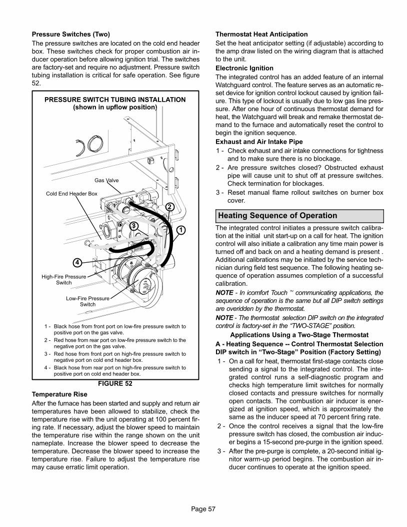
Page 57
Pressure Switches (Two)
The pressure switches are located on the cold end header
box. These switches check for proper combustion air in-
ducer operation before allowing ignition trial. The switches
are factory−set and require no adjustment. Pressure switch
tubing installation is critical for safe operation. See figure
52.
PRESSURE SWITCH TUBING INSTALLATION(shown in upflow position)
FIGURE 52
Gas Valve
Cold End Header Box
High−Fire PressureSwitch
Low−Fire PressureSwitch
1
2
3
4
1 − Black hose from front port on low−fire pressure switch topositive port on the gas valve.
2 − Red hose from rear port on low−fire pressure switch to thenegative port on the gas valve.
3 − Red hose from front port on high−fire pressure switch tonegative port on cold end header box.
4 − Black hose from rear port on high−fire pressure switch topositive port on cold end header box.
Temperature Rise
After the furnace has been started and supply and return air
temperatures have been allowed to stabilize, check the
temperature rise with the unit operating at 100 percent fir-
ing rate. If necessary, adjust the blower speed to maintain
the temperature rise within the range shown on the unit
nameplate. Increase the blower speed to decrease the
temperature. Decrease the blower speed to increase the
temperature rise. Failure to adjust the temperature rise
may cause erratic limit operation.
Thermostat Heat Anticipation
Set the heat anticipator setting (if adjustable) according to
the amp draw listed on the wiring diagram that is attached
to the unit.
Electronic Ignition
The integrated control has an added feature of an internal
Watchguard control. The feature serves as an automatic re-
set device for ignition control lockout caused by ignition fail-
ure. This type of lockout is usually due to low gas line pres-
sure. After one hour of continuous thermostat demand for
heat, the Watchguard will break and remake thermostat de-
mand to the furnace and automatically reset the control to
begin the ignition sequence.
Exhaust and Air Intake Pipe
1 − Check exhaust and air intake connections for tightness
and to make sure there is no blockage.
2 − Are pressure switches closed? Obstructed exhaust
pipe will cause unit to shut off at pressure switches.
Check termination for blockages.
3 − Reset manual flame rollout switches on burner box
cover.
Heating Sequence of Operation
The integrated control initiates a pressure switch calibra-
tion at the initial unit start−up on a call for heat. The ignition
control will also initiate a calibration any time main power is
turned off and back on and a heating demand is present .
Additional calibrations may be initiated by the service tech-
nician during field test sequence. The following heating se-
quence of operation assumes completion of a successful
calibration.
NOTE − In icomfort Touch� communicating applications, the
sequence of operation is the same but all DIP switch settings
are overidden by the thermostat.
NOTE − The thermostat selection DIP switch on the integrated
control is factory−set in the �TWO−STAGE" position.
Applications Using a Two−Stage Thermostat
A − Heating Sequence −− Control Thermostat Selection
DIP switch in �Two−Stage" Position (Factory Setting)
1 − On a call for heat, thermostat first−stage contacts close
sending a signal to the integrated control. The inte-
grated control runs a self-diagnostic program and
checks high temperature limit switches for normally
closed contacts and pressure switches for normally
open contacts. The combustion air inducer is ener-
gized at ignition speed, which is approximately the
same as the inducer speed at 70 percent firing rate.
2 − Once the control receives a signal that the low−fire
pressure switch has closed, the combustion air induc-
er begins a 15−second pre−purge in the ignition speed.
3 − After the pre−purge is complete, a 20−second initial ig-
nitor warm−up period begins. The combustion air in-
ducer continues to operate at the ignition speed.
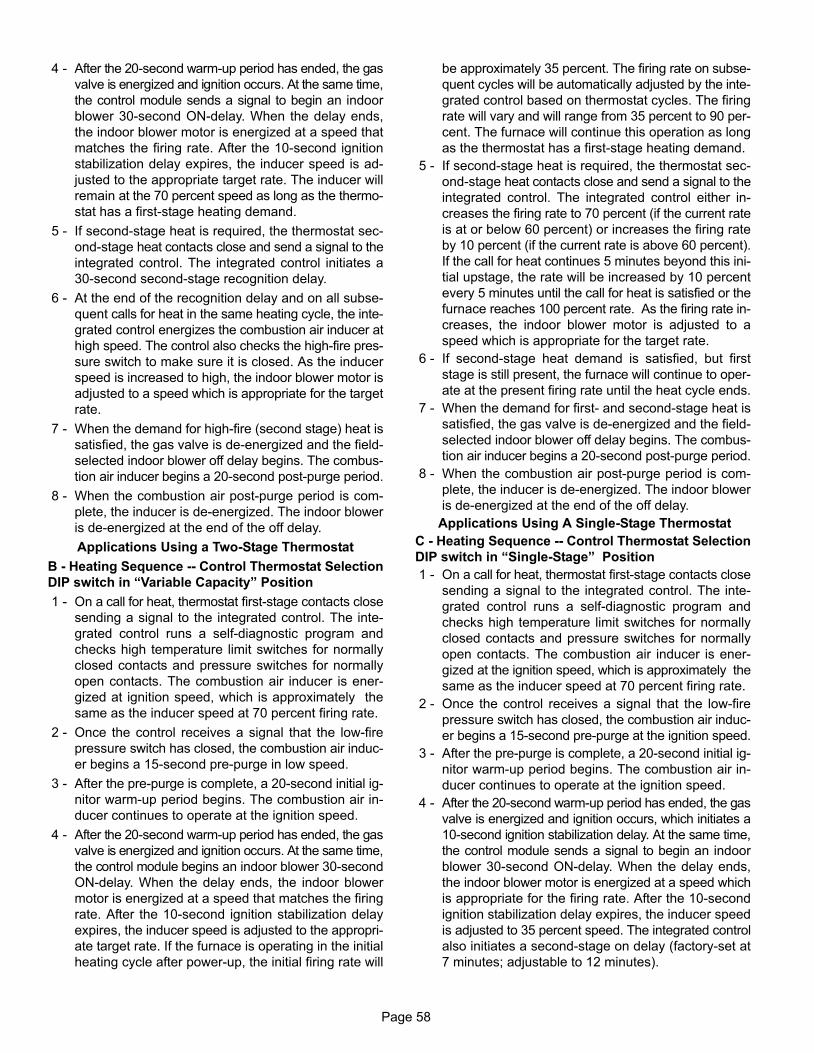
Page 58
4 − After the 20−second warm−up period has ended, the gas
valve is energized and ignition occurs. At the same time,
the control module sends a signal to begin an indoor
blower 30−second ON−delay. When the delay ends,
the indoor blower motor is energized at a speed that
matches the firing rate. After the 10−second ignition
stabilization delay expires, the inducer speed is ad-
justed to the appropriate target rate. The inducer will
remain at the 70 percent speed as long as the thermo-
stat has a first−stage heating demand.
5 − If second−stage heat is required, the thermostat sec-
ond−stage heat contacts close and send a signal to the
integrated control. The integrated control initiates a
30−second second−stage recognition delay.
6 − At the end of the recognition delay and on all subse-
quent calls for heat in the same heating cycle, the inte-
grated control energizes the combustion air inducer at
high speed. The control also checks the high−fire pres-
sure switch to make sure it is closed. As the inducer
speed is increased to high, the indoor blower motor is
adjusted to a speed which is appropriate for the target
rate.
7 − When the demand for high−fire (second stage) heat is
satisfied, the gas valve is de−energized and the field−
selected indoor blower off delay begins. The combus-
tion air inducer begins a 20−second post−purge period.
8 − When the combustion air post−purge period is com-
plete, the inducer is de−energized. The indoor blower
is de−energized at the end of the off delay.
Applications Using a Two−Stage Thermostat
B − Heating Sequence −− Control Thermostat Selection
DIP switch in �Variable Capacity" Position
1 − On a call for heat, thermostat first−stage contacts close
sending a signal to the integrated control. The inte-
grated control runs a self-diagnostic program and
checks high temperature limit switches for normally
closed contacts and pressure switches for normally
open contacts. The combustion air inducer is ener-
gized at ignition speed, which is approximately the
same as the inducer speed at 70 percent firing rate.
2 − Once the control receives a signal that the low−fire
pressure switch has closed, the combustion air induc-
er begins a 15−second pre−purge in low speed.
3 − After the pre−purge is complete, a 20−second initial ig-
nitor warm−up period begins. The combustion air in-
ducer continues to operate at the ignition speed.
4 − After the 20−second warm−up period has ended, the gas
valve is energized and ignition occurs. At the same time,
the control module begins an indoor blower 30−second
ON−delay. When the delay ends, the indoor blower
motor is energized at a speed that matches the firing
rate. After the 10−second ignition stabilization delay
expires, the inducer speed is adjusted to the appropri-
ate target rate. If the furnace is operating in the initial
heating cycle after power−up, the initial firing rate will
be approximately 35 percent. The firing rate on subse-
quent cycles will be automatically adjusted by the inte-
grated control based on thermostat cycles. The firing
rate will vary and will range from 35 percent to 90 per-
cent. The furnace will continue this operation as long
as the thermostat has a first−stage heating demand.
5 − If second−stage heat is required, the thermostat sec-
ond−stage heat contacts close and send a signal to the
integrated control. The integrated control either in-
creases the firing rate to 70 percent (if the current rate
is at or below 60 percent) or increases the firing rate
by 10 percent (if the current rate is above 60 percent).
If the call for heat continues 5 minutes beyond this ini-
tial upstage, the rate will be increased by 10 percent
every 5 minutes until the call for heat is satisfied or the
furnace reaches 100 percent rate. As the firing rate in-
creases, the indoor blower motor is adjusted to a
speed which is appropriate for the target rate.
6 − If second−stage heat demand is satisfied, but first
stage is still present, the furnace will continue to oper-
ate at the present firing rate until the heat cycle ends.
7 − When the demand for first− and second−stage heat is
satisfied, the gas valve is de−energized and the field−
selected indoor blower off delay begins. The combus-
tion air inducer begins a 20−second post−purge period.
8 − When the combustion air post−purge period is com-
plete, the inducer is de−energized. The indoor blower
is de−energized at the end of the off delay.
Applications Using A Single−Stage Thermostat
C − Heating Sequence −− Control Thermostat Selection
DIP switch in �Single−Stage" Position
1 − On a call for heat, thermostat first−stage contacts close
sending a signal to the integrated control. The inte-
grated control runs a self-diagnostic program and
checks high temperature limit switches for normally
closed contacts and pressure switches for normally
open contacts. The combustion air inducer is ener-
gized at the ignition speed, which is approximately the
same as the inducer speed at 70 percent firing rate.
2 − Once the control receives a signal that the low−fire
pressure switch has closed, the combustion air induc-
er begins a 15−second pre−purge at the ignition speed.
3 − After the pre−purge is complete, a 20−second initial ig-
nitor warm−up period begins. The combustion air in-
ducer continues to operate at the ignition speed.
4 − After the 20−second warm−up period has ended, the gas
valve is energized and ignition occurs, which initiates a
10−second ignition stabilization delay. At the same time,
the control module sends a signal to begin an indoor
blower 30−second ON−delay. When the delay ends,
the indoor blower motor is energized at a speed which
is appropriate for the firing rate. After the 10−second
ignition stabilization delay expires, the inducer speed
is adjusted to 35 percent speed. The integrated control
also initiates a second−stage on delay (factory−set at
7 minutes; adjustable to 12 minutes).
Page 59
5 − If the heating demand continues beyond the second−
stage on delay, the integrated control energizes the
combustion air inducer at 70 percent speed. The in-
door blower motor is adjusted to a speed which
matches the target rate. A fixed, 10−minute third−stage
on delay is initiated.
6 − If the heating demand continues beyond the third−
stage on delay, the integrated control energizes the in-
ducer at high speed. The indoor blower motor is ad-
justed to a speed which is appropriate for the target
rate.
7 −When the thermostat heating demand is satisfied, the
gas valve is de−energized and the combustion air in-
ducer begins a 20−second post−purge. The field−se-
lected indoor blower off delay begins.
8 − When the combustion air post−purge period is com-
plete, the inducer is de−energized. The indoor blower
is de−energized at the end of the off delay.
Service
WARNINGELECTRICAL SHOCK, FIRE,OR EXPLOSION HAZARD.
Failure to follow safety warnings exactly could resultin dangerous operation, serious injury, death orproperty damage.Improper servicing could result in dangerous opera-tion, serious injury, death, or property damage.Before servicing, disconnect all electrical power tofurnace.When servicing controls, label all wires prior to dis-connecting. Take care to reconnect wires correctly.Verify proper operation after servicing.
At the beginning of each heating season, system should bechecked as follows by a qualified service technician:
Blower
Check the blower wheel for debris and clean if necessary.The blower motors are prelubricated for extended bearinglife. No further lubrication is needed.
WARNINGThe blower access panel must be securely in placewhen the blower and burners are operating. Gasfumes, which could contain carbon monoxide, canbe drawn into living space resulting in personal inju-ry or death.
Filters
All SLP98UHV filters are installed external to the unit. Fil-ters should be inspected monthly. Clean or replace the fil-ters when necessary to ensure proper furnace operation.Table 1 lists recommended filter sizes.
Exhaust and air intake pipes
Check the exhaust and air intake pipes and all connectionsfor tightness and to make sure there is no blockage.
NOTE − After any heavy snow, ice or frozen fog event, thefurnace vent pipes may become restricted. Always checkthe vent system and remove any snow or ice that may beobstructing the plastic intake or exhaust pipes.
Electrical
1 − Check all wiring for loose connections.
2 − Check for the correct voltage at the furnace (furnaceoperating).Correct voltage is 120VAC + 10%.
3 − Check amp−draw on the blower motor with inner blow-er panel in place. Motor Nameplate__________Actual__________
Winterizing and Condensate Trap Care
1 − Turn off power to the unit.
2 − Have a shallow pan ready to empty condensate water.
3 − Remove the drain plug from the condensate trap and
empty water. Inspect the trap then reinstall the drain
plug and refill trap with water.
Cleaning Heat Exchanger
If cleaning the heat exchanger becomes necessary, follow
the below procedures and refer to figure 1 when disassem-
bling unit. Use papers or protective covering in front of fur-
nace while removing heat exchanger assembly.
1 − Turn off electrical and gas supplies to the furnace.
2 − Remove the furnace access panels.
3 − Disconnect the 2−pin plug from the gas valve.
4 − Remove gas supply line connected to gas valve. Re-
move the burner box cover and remove gas valve/
manifold assembly.
5 − Remove sensor wire from sensor. Disconnect 2-pin
plug from the ignitor.
6 − Disconnect wires from flame roll−out switches.
7 − Remove four burner box screws at the vestibule panel
and remove burner box. Set burner box assembly
aside.
NOTE − If necessary, clean burners at this time. Follow
procedures outlined in Burner Cleaning section.
8 − Loosen the clamps to the flexible exhaust coupling.
9 − Disconnect condensate drain line from the cold end
header box.
10 − Disconnect condensate drain tubing from flue collar.
Remove screws that secures the flue collar into place.
Remove flue collar. It may be necessary to cut the exit-
ing exhaust pipe for removal of the fitting.
11 − Mark and disconnect all combustion air pressure tub-
ing from cold end header collector box.
12 − Mark and remove wires from pressure switches. Re-
move pressure switches. Keep tubing attached to
pressure switches.
13 − Disconnect the 4-pin plug from the combustion air in-
ducer. Remove two screws which secure combustion
air inducer to collector box. Remove combustion air in-
ducer assembly. Remove ground wire from vest pan-
el.
14 − Remove cold end header box.
Page 60
15 − Remove electrical junction box from the side of the fur-
nace.
16 − Mark and disconnect any remaining wiring to heating
compartment components. Disengage strain relief
bushing and pull wiring and bushing through the hole in
the blower deck.
17 − Remove the primary limit from the vestibule panel.
18 − Remove two screws from the front cabinet flange at
the blower deck. Spread cabinet sides slightly to allow
clearance for removal of heat exchanger.
18 − Remove screws along vestibule sides and bottom
which secure vestibule panel and heat exchanger as-
sembly to cabinet. Remove two screws from blower
rail which secure bottom heat exchanger flange. Re-
move heat exchanger from furnace cabinet.
19 − Back wash heat exchanger with soapy water solution
or steam. If steam is used it must be below 275°F
(135°C) .
20 − Thoroughly rinse and drain the heat exchanger. Soap
solutions can be corrosive. Take care to rinse entire
assembly.
21 − Reinstall heat exchanger into cabinet making sure that
the clamshells of the heat exchanger assembly are
resting in the support located at the rear of the cabinet.
Remove the indoor blower to view this area through
the blower opening.
22 − Re-secure the supporting screws along the vestibule
sides and bottom to the cabinet.
23 − Reinstall cabinet screws on front flange at blower
deck.
24 − Reinstall the primary limit on the vestibule panel.
25 − Route heating component wiring through hole in blow-
er deck and reinsert strain relief bushing.
26 − Reinstall electrical junction box.
27 − Reinstall the cold end header box.
28 − Reinstall the combustion air inducer. Reconnect the
4−pin plug to the wire harness.
29 − Reinstall pressure switches and reconnect pressure
switch wiring.
30 − Carefully connect combustion air pressure switch
hosing from pressure switches to proper stubs on
cold end header collector box.
31 − Reconnect condensate drain line to the cold end
header box.
32 − Use securing screws to reinstall flue collar to the top
cap on the furnace. Reconnect exhaust piping and ex-
haust drain tubing.
33 − Replace flexible exhaust adapter on combustion air in-
ducer and flue collar. Secure using two existing hose
clamps.
34 − Reinstall burner box assembly in vestibule area.
35 − Reconnect flame roll−out switch wires.
36 − Reconnect sensor wire and reconnect 2−pin plug from
ignitor.
37 − Secure burner box assembly to vestibule panel using
four existing screws. Make sure burners line up in
center of burner ports.
38 − Reinstall gas valve manifold assembly. Reconnect
gas supply line to gas valve.
39 − Reinstall burner box cover.
40 − Reconnect 2−pin plug to gas valve.
41 − Replace the blower compartment access panel.
42 − Refer to instruction on verifying gas and electrical con-
nections when re−establishing supplies.
43 − Follow lighting instructions to light and operate fur-
nace for 5 minutes to ensure that heat exchanger is
clean and dry and that furnace is operating properly.
44 − Replace heating compartment access panel.
Cleaning the Burner Assembly
1 − Turn off electrical and gas power supplies to furnace.
Remove upper and lower furnace access panels.
2 − Disconnect the 2−pin plug from the gas valve.
3 − Remove the burner box cover.
4 − Disconnect the gas supply line from the gas valve. Re-
move gas valve/manifold assembly.
5 − Mark and disconnect sensor wire from the sensor. Dis-
connect wires from flame rollout switches.
6 − Remove four screws which secure burner box assem-
bly to vest panel. Remove burner box from the unit.
7 − Use the soft brush attachment on a vacuum cleaner to
gently clean the face of the burners. Visually inspect
the inside of the burners and crossovers for any block-
age caused by foreign matter. Remove any blockage.
8 − Reinstall the burner box assembly using the existing
four screws. Make sure that the burners line up in the
center of the burner ports.
9 − Reconnect the sensor wire and reconnect the 2−pin
plug to the ignitor wiring harness. Reconnect wires to
flame rollout switches.
10 − Reinstall the gas valve manifold assembly. Reconnect
the gas supply line to the gas valve. Reinstall the burn-
er box cover.
11 − Reconnect 2−pin plug to gas valve.
12 − Replace the blower compartment access panel.
13 − Refer to instruction on verifying gas and electrical con-
nections when re−establishing supplies.
14 − Follow lighting instructions to light and operate fur-
nace for 5 minutes to ensure that heat exchanger is
clean and dry and that furnace is operating properly.
15 − Replace heating compartment access panel.
Page 61
Planned Service
A service technician should check the following items during an annual inspection. Power to the unit must be shut off for
the service technician’s safety.
Burners − Must be inspected for rust, dirt, or signs of water.
Vent pipe − Must be inspected for signs of water, cracked,
damaged or sagging pipe, or disconnected joints.
Unit appearance − Must be inspected for rust, dirt, signs
of water, burnt or damaged wires, or components.
Blower access door − Must be properly in place and pro-
vide a seal between the return air and the room where the
furnace is installed.
Return air duct − Must be properly attached and provide
an air seal to the unit.
Operating performance − Unit must be observed during
operation to monitor proper performance of the unit and the
vent system.
Combustion gases − Flue products must be analyzed and
compared to the unit specifications.
Problems detected during the inspection may make it nec-
essary to temporarily shut down the furnace until the items
can be repaired or replaced.
Instruct the homeowners to pay attention to their
furnace. Situations can arise between annual furnace in-
spections that may result in unsafe operation.
Repair Parts List
The following repair parts are available through Lennox dealers. When ordering parts, include the complete furnace model
number listed on the nameplate −− Example: SLP98UH070V36B. All service must be performed by a licensed profes-
sional installer (or equivalent), service agency, or gas supplier.
Cabinet Parts
Outer access panel
Blower access panel
Top cap
Control Panel Parts
Transformer
Integrated control
Door interlock switch
Circuit breaker
Blower Parts
Blower wheel
Motor
Motor mounting frame
Blower housing cut−off plate
Power choke (1HP only)
Heating Parts
Flame sensor
Heat exchanger assembly
Gas manifold
Combustion air inducer
Gas valve
Main burner cluster
Main burner orifices
Pressure switches
Ignitor
Primary limit control
Flame rollout switches
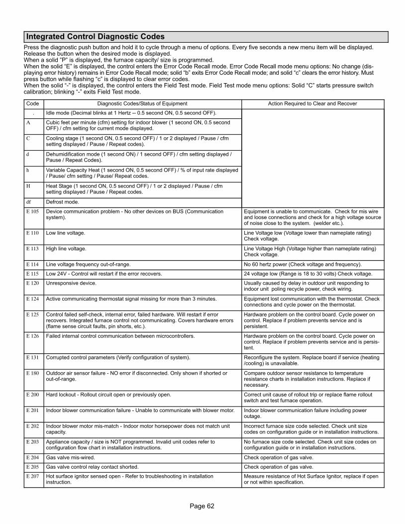
Page 62
Integrated Control Diagnostic Codes
Press the diagnostic push button and hold it to cycle through a menu of options. Every five seconds a new menu item will be displayed.Release the button when the desired mode is displayed. When a solid "P" is displayed, the furnace capacity/ size is programmed.When the solid �E" is displayed, the control enters the Error Code Recall mode. Error Code Recall mode menu options: No change (dis-playing error history) remains in Error Code Recall mode; solid �b" exits Error Code Recall mode; and solid �c" clears the error history. Mustpress button while flashing �c" is displayed to clear error codes. When the solid �−" is displayed, the control enters the Field Test mode. Field Test mode menu options: Solid �C" starts pressure switchcalibration; blinking �−" exits Field Test mode.
Code Diagnostic Codes/Status of Equipment Action Required to Clear and Recover
. Idle mode (Decimal blinks at 1 Hertz −− 0.5 second ON, 0.5 second OFF).
A Cubic feet per minute (cfm) setting for indoor blower (1 second ON, 0.5 secondOFF) / cfm setting for current mode displayed.
C Cooling stage (1 second ON, 0.5 second OFF) / 1 or 2 displayed / Pause / cfmsetting displayed / Pause / Repeat codes).
d Dehumidification mode (1 second ON) / 1 second OFF) / cfm setting displayed /Pause / Repeat Codes).
h Variable Capacity Heat (1 second ON, 0.5 second OFF) / % of input rate displayed/ Pause/ cfm setting / Pause/ Repeat codes.
H Heat Stage (1 second ON, 0.5 second OFF) / 1 or 2 displayed / Pause / cfmsetting displayed / Pause / Repeat codes.
df Defrost mode.
E 105 Device communication problem − No other devices on BUS (Communicationsystem).
Equipment is unable to communicate. Check for mis wireand loose connections and check for a high voltage sourceof noise close to the system. (welder etc.).
E 110 Low line voltage. Line Voltage low (Voltage lower than nameplate rating)Check voltage.
E 113 High line voltage. Line Voltage High (Voltage higher than nameplate rating)Check voltage.
E 114 Line voltage frequency out−of−range. No 60 hertz power (Check voltage and frequency).
E 115 Low 24V − Control will restart if the error recovers. 24 voltage low (Range is 18 to 30 volts) Check voltage.
E 120 Unresponsive device. Usually caused by delay in outdoor unit responding toindoor unit poling recycle power, check wiring.
E 124 Active communicating thermostat signal missing for more than 3 minutes. Equipment lost communication with the thermostat. Checkconnections and cycle power on the thermostat.
E 125 Control failed self−check, internal error, failed hardware. Will restart if errorrecovers. Integrated furnace control not communicating. Covers hardware errors(flame sense circuit faults, pin shorts, etc.).
Hardware problem on the control board. Cycle power oncontrol. Replace if problem prevents service and ispersistent.
E 126 Failed internal control communication between microcontrollers. Hardware problem on the control board. Cycle power oncontrol. Replace if problem prevents service and is persis-tent.
E 131 Corrupted control parameters (Verify configuration of system). Reconfigure the system. Replace board if service (heating/cooling) is unavailable.
E 180 Outdoor air sensor failure − NO error if disconnected. Only shown if shorted orout−of−range.
Compare outdoor sensor resistance to temperatureresistance charts in installation instructions. Replace ifnecessary.
E 200 Hard lockout − Rollout circuit open or previously open. Correct unit cause of rollout trip or replace flame rolloutswitch and test furnace operation.
E 201 Indoor blower communication failure − Unable to communicate with blower motor. Indoor blower communication failure including poweroutage.
E 202 Indoor blower motor mis−match − Indoor motor horsepower does not match unitcapacity.
Incorrect furnace size code selected. Check unit sizecodes on configuration guide or in installation instructions.
E 203 Appliance capacity / size is NOT programmed. Invalid unit codes refer toconfiguration flow chart in installation instructions.
No furnace size code selected. Check unit size codes onconfiguration guide or in installation instructions.
E 204 Gas valve mis−wired. Check operation of gas valve.
E 205 Gas valve control relay contact shorted. Check operation of gas valve.
E 207 Hot surface ignitor sensed open − Refer to troubleshooting in installationinstruction.
Measure resistance of Hot Surface Ignitor, replace if openor not within specification.
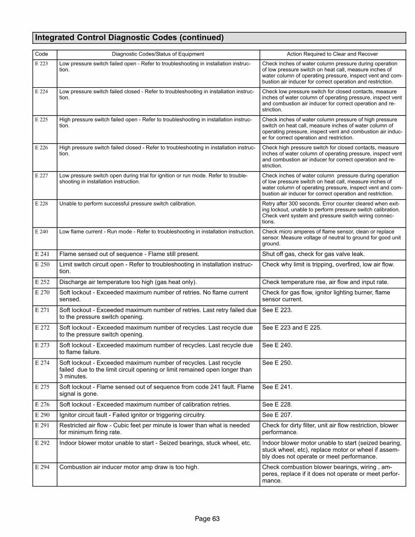
Page 63
Integrated Control Diagnostic Codes (continued)
Code Diagnostic Codes/Status of Equipment Action Required to Clear and Recover
E 223 Low pressure switch failed open − Refer to troubleshooting in installation instruc-tion.
Check inches of water column pressure during operationof low pressure switch on heat call, measure inches ofwater column of operating pressure, inspect vent and com-bustion air inducer for correct operation and restriction.
E 224 Low pressure switch failed closed − Refer to troubleshooting in installation instruc-tion.
Check low pressure switch for closed contacts, measureinches of water column of operating pressure, inspect ventand combustion air inducer for correct operation and re-striction.
E 225 High pressure switch failed open − Refer to troubleshooting in installation instruc-tion.
Check inches of water column pressure of high pressureswitch on heat call, measure inches of water column ofoperating pressure, inspect vent and combustion air induc-er for correct operation and restriction.
E 226 High pressure switch failed closed − Refer to troubleshooting in installation instruc-tion.
Check high pressure switch for closed contacts, measureinches of water column of operating pressure, inspect ventand combustion air inducer for correct operation and re-striction.
E 227 Low pressure switch open during trial for ignition or run mode. Refer to trouble-shooting in installation instruction.
Check inches of water column pressure during operationof low pressure switch on heat call, measure inches ofwater column of operating pressure, inspect vent and com-bustion air inducer for correct operation and restriction.
E 228 Unable to perform successful pressure switch calibration. Retry after 300 seconds. Error counter cleared when exit-ing lockout, unable to perform pressure switch calibration.Check vent system and pressure switch wiring connec-tions.
E 240 Low flame current − Run mode − Refer to troubleshooting in installation instruction. Check micro amperes of flame sensor, clean or replacesensor. Measure voltage of neutral to ground for good unitground.
E 241 Flame sensed out of sequence − Flame still present. Shut off gas, check for gas valve leak.
E 250 Limit switch circuit open − Refer to troubleshooting in installation instruc-tion.
Check why limit is tripping, overfired, low air flow.
E 252 Discharge air temperature too high (gas heat only). Check temperature rise, air flow and input rate.
E 270 Soft lockout − Exceeded maximum number of retries. No flame currentsensed.
Check for gas flow, ignitor lighting burner, flamesensor current.
E 271 Soft lockout − Exceeded maximum number of retries. Last retry failed dueto the pressure switch opening.
See E 223.
E 272 Soft lockout − Exceeded maximum number of recycles. Last recycle dueto the pressure switch opening.
See E 223 and E 225.
E 273 Soft lockout − Exceeded maximum number of recycles. Last recycle dueto flame failure.
See E 240.
E 274 Soft lockout − Exceeded maximum number of recycles. Last recyclefailed due to the limit circuit opening or limit remained open longer than3 minutes.
See E 250.
E 275 Soft lockout − Flame sensed out of sequence from code 241 fault. Flamesignal is gone.
See E 241.
E 276 Soft lockout − Exceeded maximum number of calibration retries. See E 228.
E 290 Ignitor circuit fault − Failed ignitor or triggering circuitry. See E 207.
E 291 Restricted air flow − Cubic feet per minute is lower than what is neededfor minimum firing rate.
Check for dirty filter, unit air flow restriction, blowerperformance.
E 292 Indoor blower motor unable to start − Seized bearings, stuck wheel, etc. Indoor blower motor unable to start (seized bearing,stuck wheel, etc), replace motor or wheel if assem-bly does not operate or meet performance.
E 294 Combustion air inducer motor amp draw is too high. Check combustion blower bearings, wiring , am-peres, replace if it does not operate or meet perfor-mance.
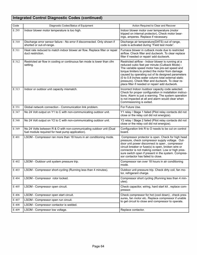
Page 64
Integrated Control Diagnostic Codes (continued)
Code Diagnostic Codes/Status of Equipment Action Required to Clear and Recover
E 295 Indoor blower motor temperature is too high. Indoor blower motor over temperature (motortripped on internal protector), Check motor bear-ings, amperes. Replace if necessary.
E 310 Discharge error sensor failure − No error if disconnected. Only shown ifshorted or out−of−range.
Discharge air temperature(DATS) out of range,code is activated during "Field test mode".
E 311 Heat rate reduced to match indoor blower air flow. Replace filter or repairduct restriction.
Furnace blower in cutback mode due to restrictedairflow. Check filter and ductwork. To clear replacefilter if needed or repair/ add ductwork.
E 312 Restricted air flow in cooling or continuous fan mode is lower than cfmsetting.
Restricted airflow − Indoor blower is running at areduced cubic feet per minute (Cutback Mode) −The variable speed motor has pre−set speed andtorque limiters to protect the motor from damagecaused by operating out of its designed parameters(0 to 0.8 inches water column total external staticpressure). Check filter and ductwork. To clear re-place filter if needed or repair/ add ductwork.
E 313 Indoor or outdoor unit capacity mismatch. Incorrect Indoor /outdoor capacity code selected.Check for proper configuration in installation instruc-tions. Alarm is just a warning. The system operationis not impacted at all and alarm would clear whenCommissioning is exited.
E 331 Global network connection − Communication link problem. For Future Use.
E 347 No 24 Volt output on Y1 to C with non−communicating outdoor unit. Y1 relay / Stage 1 failed (Pilot relay contacts did notclose or the relay coil did not energize).
E 348 No 24 Volt output on Y2 to C with non−communicating outdoor unit. Y2 relay / Stage 2 failed (Pilot relay contacts did notclose or the relay coil did not energize).
E 349 No 24 Volts between R & O with non−communicating outdoor unit (Dualfuel module required for heat pump application).
Configuration link R to O needs to be cut on controlboard.
E 401 LSOM − Compressor ran more than 18 hours in air conditioning mode. Compressor protector is open. Check for high headpressure, check compressor supply voltage. Out-door unit power disconnect is open , compressorcircuit breaker or fuse(s) is open, broken wire orconnector is not making contact. Low or high pres-sure switch open if present in the system. Compres-sor contactor has failed to close.
E 402 LSOM − Outdoor unit system pressure trip. Compressor ran over 18 hours in air conditioningmode.
E 403 LSOM − Compressor short−cycling (Running less than 4 minutes). Outdoor unit pressure trip. Check dirty coil, fan mo-tor, refrigerant charge.
E 404 LSOM − Compressor rotor locked. Compressor short cycling (Running less than 4 min-utes).
E 405 LSOM − Compressor open circuit. Check capacitor, wiring, hard start kit , replace com-pressor.
E 406 LSOM − Compressor open start circuit. Check compressor for hot (cool down) , check pres-sures, fan motor etc. Replace compressor if unableto get circuit to close and compressor to operate.
E 407 LSOM − Compressor open run circuit.
E 408 LSOM − Compressor contactor is welded.
E 409 LSOM − Compressor low voltage. Replace contactor.
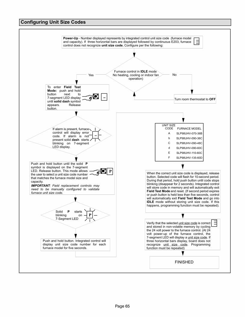
Page 65
Configuring Unit Size Codes
Power−Up − Number displayed represents by integrated control unit size code (furnace modeland capacity). If three horizontal bars are displayed followed by continuous E203, furnacecontrol does not recognize unit size code. Configure per the following:
Furnace control in IDLE mode No heating, cooling or indoor fan
operation)
To enter Field TestMode: push and holdbutton next to7−segment LED displayuntil solid dash symbolappears. Releasebutton.
Turn room thermostat to OFF
Push and hold button until the solid Psymbol is displayed on the 7−segmentLED. Release button. This mode allowsthe user to select a unit size code numberthat matches the furnace model size andcapacity.
Solid P startsblinking on7−Segment LED
Push and hold button. Integrated control willdisplay unit size code number for eachfurnace model for five seconds.
When the correct unit size code is displayed, releasebutton. Selected code will flash for 10−second period.During that period, hold push button until code stopsblinking (disappear for 2 seconds). Integrated controlwill store code in memory and will automatically exitField Test Mode and reset. (If second period expiresor push button is held less than five seconds, controlwill automatically exit Field Test Mode and go intoIDLE mode without storing unit size code. If thishappens, programming function must be repeated).
Verify that the selected unit size code is correctand stored in non−volatile memory by cyclingthe 24 volt power to the furnace control. (At 24volt power−up of the furnace control, the7−segment LED will display a unit size code. Ifthree horizontal bars display, board does notrecognize unit size code. Programmingfunction must be repeated)
Yes No
IMPORTANT: Field replacement controls mayneed to be manually configured to validatefurnace unit size code.
FURNACE MODEL
SLP98UHV−070−36B
SLP98UHV−090−36C
SLP98UHV−090−48C
SLP98UHV−090−60C
SLP98UHV−110−60C
SLP98UHV−135−60D
UNIT SIZE CODE
A
b
C
d
E
F
−−−
_
_
P
P
−−−
If alarm is present, furnacecontrol will display errorcode. If alarm is notpresent solid dash startsblinking on 7−segmentLED display.
FINISHED
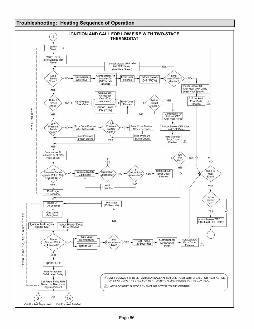
Page 66
Troubleshooting: Heating Sequence of Operation
IGNITION AND CALL FOR LOW FIRE WITH TWO−STAGETHERMOSTAT
Call For 2nd Stage Heat Call For Heat Satisfied
LimitSwitch
Closed?
LimitCloses Within 3
Minutes?
NO
Soft Lockout:Error Code
Flashes
flashes
YES
RolloutCircuit
Closed?
LowPressureSwitchOpen?
LowPressure Switch
Closed Within 150Seconds?
HighPressureSwitchOpen?
YES
NO
NO
NO
NO
YES
NO
De−EnergizeGas Valve
De−EnergizeGas Valve
Error CodeFlashes
Error CodeFlashes
RolloutCircuit
Closes?
Hard Lockout:Error Code
Flashes
Error Code FlashesAfter 5 Seconds
Error Code FlashesAfter 5 Seconds
LIGHT
OFF
SafetyCheck
After
(Low Heat Speed)
Verify ThereIs No Main Burner
Flame
YES
YES
Low PressureSwitch Opens
High PressureSwitch Opens
YES
NOPressure Switch
Calibration
Pre−Purge15 Seconds
YES
Gas ValveEnergized
FlameSensed Within
4 seconds?
Gas ValveDe−energized
Interpurge(15 Seconds)
5thUnsuccessful
Trial?
Wait For IgnitionStabilization Delay
Post−Purge(20Seconds)
Soft Lockout:Error Code
FlashesYES
NO
NO
YES
Call ForHeat
Ends?
NO
YES
YES NOCALL
FOR
1ST
STAGE
HEAT
3A2
1
1
OR
CallFor
Heat?NO
4CalibrationsAttempted?
CalibrationSuccessful?
Wait5 minutes
NO
NOSoft Lockout:Error Code
FlashesYES
YES
YES
2
1
1
2
Set Target Firing RateBased on Thermostat
Signals Present
SOFT LOCKOUT IS RESET AUTOMATICALLY AFTER ONE HOUR WITH A CALL FOR HEAT ACTIVE,OR BY CYCLING THE CALL FOR HEAT, OR BY CYCLING POWER TO THE CONTROL.
HARD LOCKOU T IS RESET BY CYCLING POWER TO THE CONTROL.
1
2
Indoor blower OFF
Combustion AirInducer On(100% rate
speed)
Indoor BlowerON (100%)
Heat OFF Delay
Indoor Blower OFFAfter Heat OFF Delay(High Heat Speed)
CombustionAir InducerOn (100%
rate speed)
Indoor BlowerON (70%)
Combustion AirInducer OFF
After Post−Purge
Indoor Blower OFF AfterHeat OFF Delay
Combustion AirInducer ON at 70%
Rate Speed
Ignitor ON20 Seconds
IndoorBlower
ON?
Indoor blower OFFAfter Heat OFF Delay
Indoor Blower DelayTimer Started
Ignition Trial Begins(Ignitor ON)
Ignitor OFF
Ignitor OFF
CombustionAir Inducer
OFF
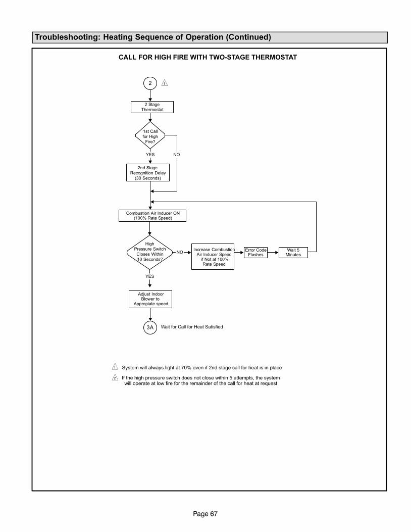
Page 67
Troubleshooting: Heating Sequence of Operation (Continued)
CALL FOR HIGH FIRE WITH TWO−STAGE THERMOSTAT
1st Call
for High
Fire?
Wait for Call for Heat Satisfied
2 Stage
Thermostat
2nd Stage
Recognition Delay
(30 Seconds)
YES
High
Pressure Switch
Closes Within
10 Seconds?
NOError Code
Flashes
NO
YES
Wait 5Minutes
3A
2
1
2
1
System will always light at 70% even if 2nd stage call for heat is in place
If the high pressure switch does not close within 5 attempts, the systemwill operate at low fire for the remainder of the call for heat at request
Combustion Air Inducer ON(100% Rate Speed)
Increase CombustionAir Inducer Speed
if Not at 100%Rate Speed
Adjust IndoorBlower to
Appropiate speed
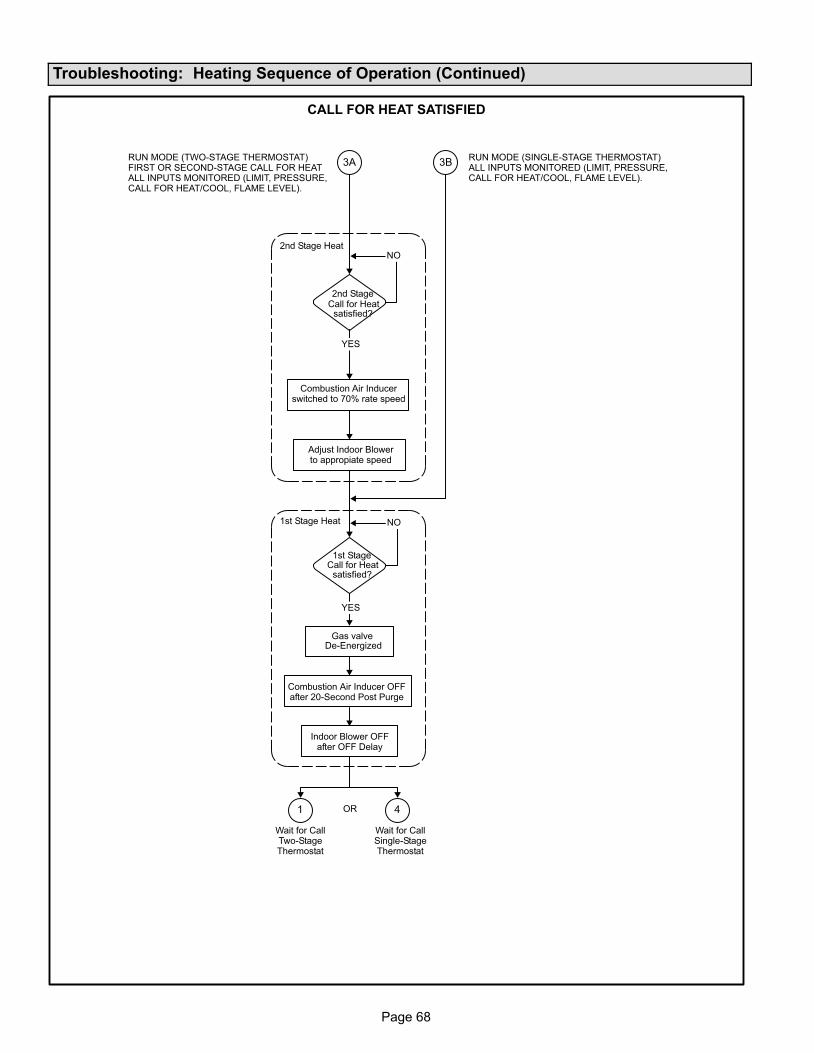
Page 68
Troubleshooting: Heating Sequence of Operation (Continued)
CALL FOR HEAT SATISFIED
1st Stage Heat
2nd Stage Heat
2nd StageCall for Heat
satisfied?
NO
1st StageCall for Heat
satisfied?
Gas valveDe−Energized
YES
NO
1 4
3A 3B
YES
OR
Combustion Air Inducerswitched to 70% rate speed
Adjust Indoor Blowerto appropiate speed
Combustion Air Inducer OFFafter 20−Second Post Purge
Indoor Blower OFFafter OFF Delay
RUN MODE (SINGLE−STAGE THERMOSTAT)ALL INPUTS MONITORED (LIMIT, PRESSURE,CALL FOR HEAT/COOL, FLAME LEVEL).
RUN MODE (TWO−STAGE THERMOSTAT)FIRST OR SECOND−STAGE CALL FOR HEATALL INPUTS MONITORED (LIMIT, PRESSURE,CALL FOR HEAT/COOL, FLAME LEVEL).
Wait for CallTwo−StageThermostat
Wait for CallSingle−StageThermostat
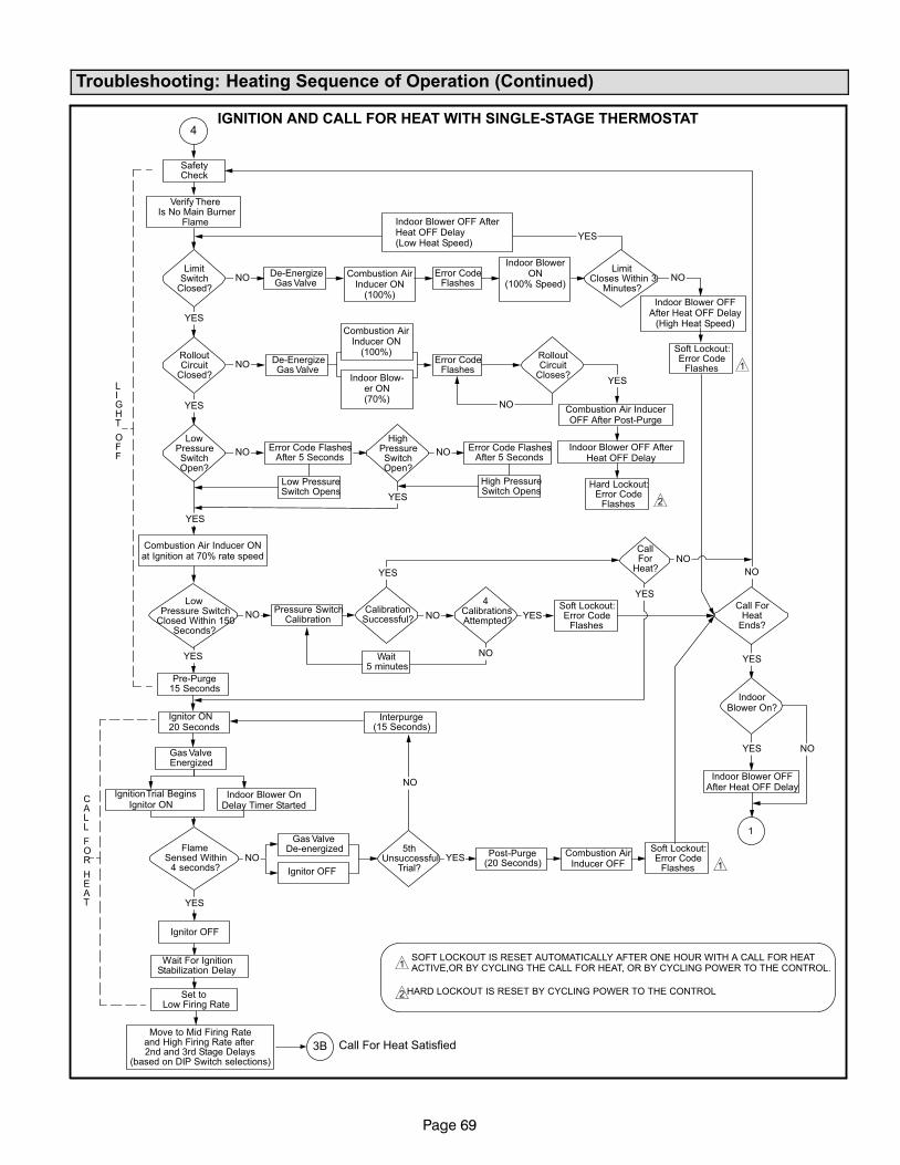
Page 69
Troubleshooting: Heating Sequence of Operation (Continued)
IGNITION AND CALL FOR HEAT WITH SINGLE−STAGE THERMOSTAT
Call For Heat Satisfied
LimitSwitch
Closed?
LimitCloses Within 3
Minutes?NO
Soft Lockout:Error Code
Flashes
flashes
YES
RolloutCircuit
Closed?
LowPressureSwitchOpen?
LowPressure Switch
Closed Within 150Seconds?
HighPressureSwitchOpen?
YES
NO
NO
NO
NO
YES
NO
De−EnergizeGas Valve
De−EnergizeGas Valve
Error CodeFlashes
Error CodeFlashes
RolloutCircuit
Closes?
Hard Lockout:Error Code
Flashes
Error Code FlashesAfter 5 Seconds
Error Code FlashesAfter 5 Seconds
LIGHT
OFF
SafetyCheck
Verify ThereIs No Main Burner
Flame
YES
YES
Low PressureSwitch Opens
High PressureSwitch Opens
YES
NO
Pre−Purge15 Seconds
YES
Gas ValveEnergized
IgnitionTrial Begins
FlameSensed Within
4 seconds?
Gas ValveDe−energized
Interpurge(15 Seconds)
5thUnsuccessful
Trial?
Wait For IgnitionStabilization Delay
Post−Purge(20 Seconds)
Soft Lockout:Error Code
FlashesYES
NO
NO
YES
Call ForHeat
Ends?
NO
YES
YES NO
CALL
FOR
HEAT
3B
1
4
Move to Mid Firing Rateand High Firing Rate after2nd and 3rd Stage Delays
(based on DIP Switch selections)
Pressure SwitchCalibration
CallFor
Heat?NO
4CalibrationsAttempted?
CalibrationSuccessful?
Wait5 minutes
NO
NOSoft Lockout:Error Code
FlashesYES
YES
YES
1
2
1
2
1
Set toLow Firing Rate
Indoor Blower OFF AfterHeat OFF Delay(Low Heat Speed)
Combustion AirInducer ON
(100%)
Indoor BlowerON
(100% Speed)
Indoor Blower OFFAfter Heat OFF Delay
(High Heat Speed)Combustion Air
Inducer ON(100%)
Indoor Blow-er ON(70%)
Combustion Air InducerOFF After Post−Purge
Indoor Blower OFF AfterHeat OFF Delay
Combustion Air Inducer ONat Ignition at 70% rate speed
IndoorBlower On?
Indoor Blower OFFAfter Heat OFF Delay
Ignitor ON20 Seconds
Ignitor ONIndoor Blower On
Delay Timer Started
Ignitor OFF
Combustion AirInducer OFF
Ignitor OFF
SOFT LOCKOUT IS RESET AUTOMATICALLY AFTER ONE HOUR WITH A CALL FOR HEATACTIVE,OR BY CYCLING THE CALL FOR HEAT, OR BY CYCLING POWER TO THE CONTROL.
HARD LOCKOUT IS RESET BY CYCLING POWER TO THE CONTROL
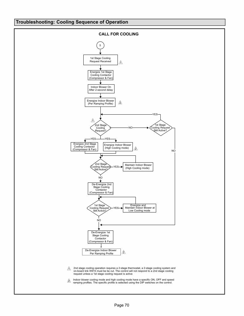
Page 70
Troubleshooting: Cooling Sequence of Operation
CALL FOR COOLING
1st Stage Cooling
Request Received
Energize 1st StageCooling Contactor
(Compressor & Fan)
2nd StageCooling
Request?
YES
2nd StageCooling Request
Still Active?
De−Energize 1stStage Cooling
Contactor(Compressor & Fan)
YES
1st StageCooling Request
Still Active?
NO
YES
YES
Energize 2nd StageCooling Contactor
(Compressor & Fan)
1st StageCooling Request
Still Active?
De−Energize 2ndStage Cooling
Contactor(Compressor & Fan)
Energize and
Low Cooling mode
(High Cooling mode)
(High Cooling mode)
Per Ramping Profile
NO
NO
YES
NO
5
1
2
1
2
2
2
1
Indoor Blower OnAfter 2−second delay
Energize Indoor Blower(Per Ramping Profile)
Energize Indoor Blower
Maintain Indoor Blower
Maintain Indoor Blower at
De−Energize Indoor Blower
2nd stage cooling operation requires a 2−stage thermostat, a 2−stage cooling system andon−board link W915 must be be cut. The control will not respond to a 2nd stage coolingrequest unless a 1st stage cooling request is active
Indoor blower cooling mode and high cooling mode have a specific ON, OFF and speedramping profiles. The specific profile is selected using the DIP switches on the control.
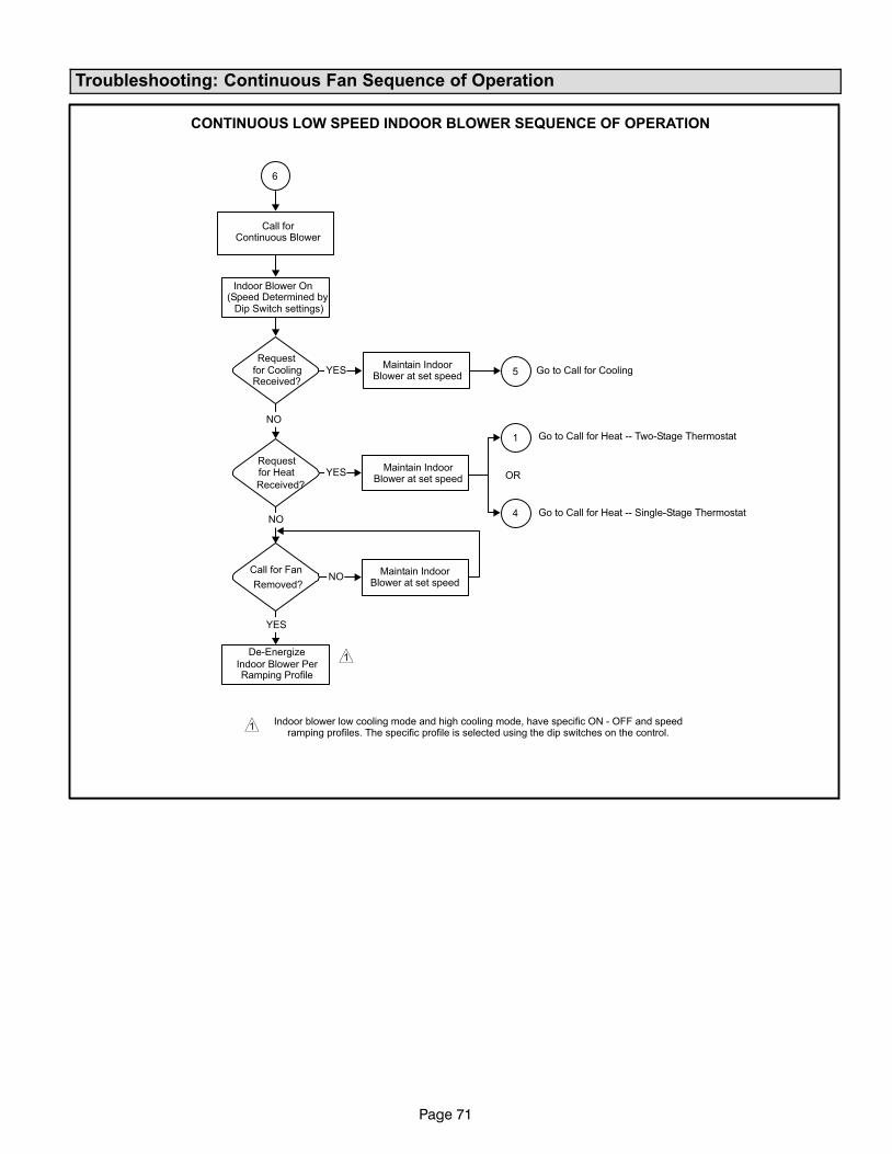
Page 71
Troubleshooting: Continuous Fan Sequence of Operation
CONTINUOUS LOW SPEED INDOOR BLOWER SEQUENCE OF OPERATION
(Speed Determined byDip Switch settings)
De−Energize
Ramping Profile
NO
Requestfor Heat
Received?
Requestfor CoolingReceived?
NO
YES
Call for Fan
Removed?
YES
NO
YES Go to Call for Cooling
6
1
4
5
1
Call forContinuous Blower
Indoor Blower On
Maintain IndoorBlower at set speed
Maintain IndoorBlower at set speed OR
Maintain IndoorBlower at set speed
Indoor Blower Per
Indoor blower low cooling mode and high cooling mode, have specific ON − OFF and speedramping profiles. The specific profile is selected using the dip switches on the control.
1
Go to Call for Heat −− Two−Stage Thermostat
Go to Call for Heat −− Single−Stage Thermostat
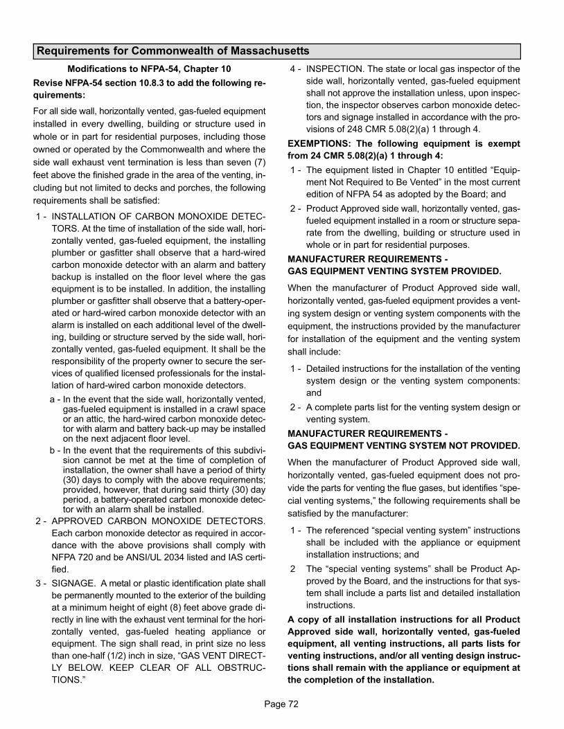
Page 72
Requirements for Commonwealth of Massachusetts
Modifications to NFPA−54, Chapter 10
Revise NFPA−54 section 10.8.3 to add the following re-
quirements:
For all side wall, horizontally vented, gas−fueled equipment
installed in every dwelling, building or structure used in
whole or in part for residential purposes, including those
owned or operated by the Commonwealth and where the
side wall exhaust vent termination is less than seven (7)
feet above the finished grade in the area of the venting, in-
cluding but not limited to decks and porches, the following
requirements shall be satisfied:
1 − INSTALLATION OF CARBON MONOXIDE DETEC-
TORS. At the time of installation of the side wall, hori-
zontally vented, gas−fueled equipment, the installing
plumber or gasfitter shall observe that a hard−wired
carbon monoxide detector with an alarm and battery
backup is installed on the floor level where the gas
equipment is to be installed. In addition, the installing
plumber or gasfitter shall observe that a battery−oper-
ated or hard−wired carbon monoxide detector with an
alarm is installed on each additional level of the dwell-
ing, building or structure served by the side wall, hori-
zontally vented, gas−fueled equipment. It shall be the
responsibility of the property owner to secure the ser-
vices of qualified licensed professionals for the instal-
lation of hard−wired carbon monoxide detectors.
a − In the event that the side wall, horizontally vented,gas−fueled equipment is installed in a crawl spaceor an attic, the hard−wired carbon monoxide detec-tor with alarm and battery back−up may be installedon the next adjacent floor level.
b − In the event that the requirements of this subdivi-sion cannot be met at the time of completion ofinstallation, the owner shall have a period of thirty(30) days to comply with the above requirements;provided, however, that during said thirty (30) dayperiod, a battery−operated carbon monoxide detec-tor with an alarm shall be installed.
2 − APPROVED CARBON MONOXIDE DETECTORS.
Each carbon monoxide detector as required in accor-
dance with the above provisions shall comply with
NFPA 720 and be ANSI/UL 2034 listed and IAS certi-
fied.
3 − SIGNAGE. A metal or plastic identification plate shall
be permanently mounted to the exterior of the building
at a minimum height of eight (8) feet above grade di-
rectly in line with the exhaust vent terminal for the hori-
zontally vented, gas−fueled heating appliance or
equipment. The sign shall read, in print size no less
than one−half (1/2) inch in size, �GAS VENT DIRECT-
LY BELOW. KEEP CLEAR OF ALL OBSTRUC-
TIONS."
4 − INSPECTION. The state or local gas inspector of the
side wall, horizontally vented, gas−fueled equipment
shall not approve the installation unless, upon inspec-
tion, the inspector observes carbon monoxide detec-
tors and signage installed in accordance with the pro-
visions of 248 CMR 5.08(2)(a) 1 through 4.
EXEMPTIONS: The following equipment is exempt
from 24 CMR 5.08(2)(a) 1 through 4:
1 − The equipment listed in Chapter 10 entitled �Equip-
ment Not Required to Be Vented" in the most current
edition of NFPA 54 as adopted by the Board; and
2 − Product Approved side wall, horizontally vented, gas−
fueled equipment installed in a room or structure sepa-
rate from the dwelling, building or structure used in
whole or in part for residential purposes.
MANUFACTURER REQUIREMENTS −
GAS EQUIPMENT VENTING SYSTEM PROVIDED.
When the manufacturer of Product Approved side wall,
horizontally vented, gas−fueled equipment provides a vent-
ing system design or venting system components with the
equipment, the instructions provided by the manufacturer
for installation of the equipment and the venting system
shall include:
1 − Detailed instructions for the installation of the venting
system design or the venting system components:
and
2 − A complete parts list for the venting system design or
venting system.
MANUFACTURER REQUIREMENTS −
GAS EQUIPMENT VENTING SYSTEM NOT PROVIDED.
When the manufacturer of Product Approved side wall,
horizontally vented, gas−fueled equipment does not pro-
vide the parts for venting the flue gases, but identifies �spe-
cial venting systems," the following requirements shall be
satisfied by the manufacturer:
1 − The referenced �special venting system" instructions
shall be included with the appliance or equipment
installation instructions; and
2 The �special venting systems" shall be Product Ap-
proved by the Board, and the instructions for that sys-
tem shall include a parts list and detailed installation
instructions.
A copy of all installation instructions for all Product
Approved side wall, horizontally vented, gas−fueled
equipment, all venting instructions, all parts lists for
venting instructions, and/or all venting design instruc-
tions shall remain with the appliance or equipment at
the completion of the installation.