installation instructions ford, c-max - 2011 > · installation instructions 1 of 14 ford, c-max...
TRANSCRIPT
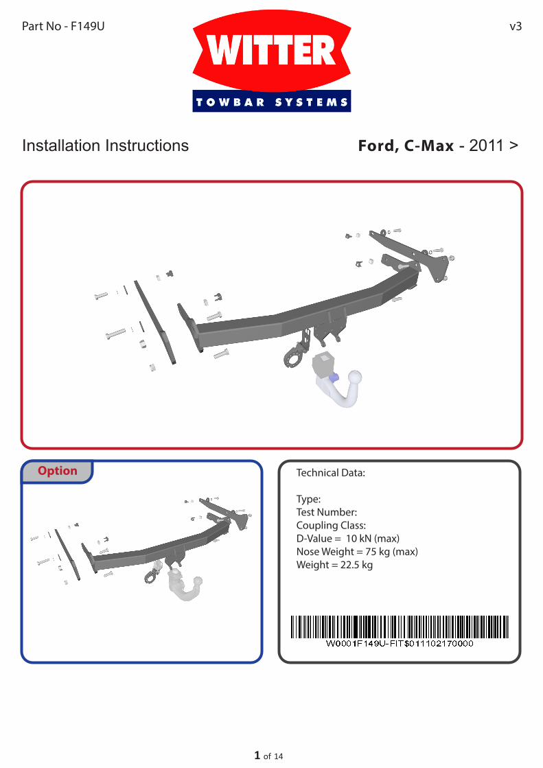
Technical Data:
Type:Test Number: Coupling Class: D-Value = 10 kN (max)Nose Weight = 75 kg (max)Weight = 22.5 kg
Installation Instructions
1 of 14
Ford, C-Max - 2011 >
Part No - F149U
Option
v3
2 of 14
Installation Instructions for Ford, C-Max - 2011 >Part No - F149U
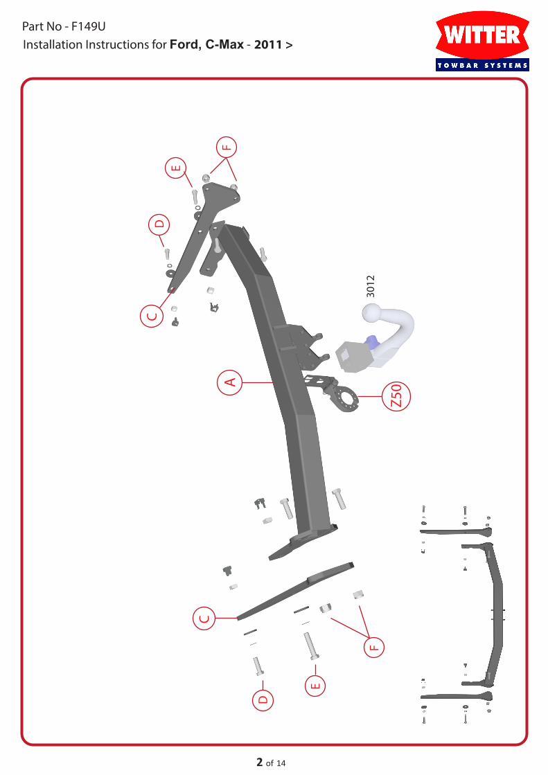
Z50A
F
F
D
D
E
E
C
C
3012
? KG
KG
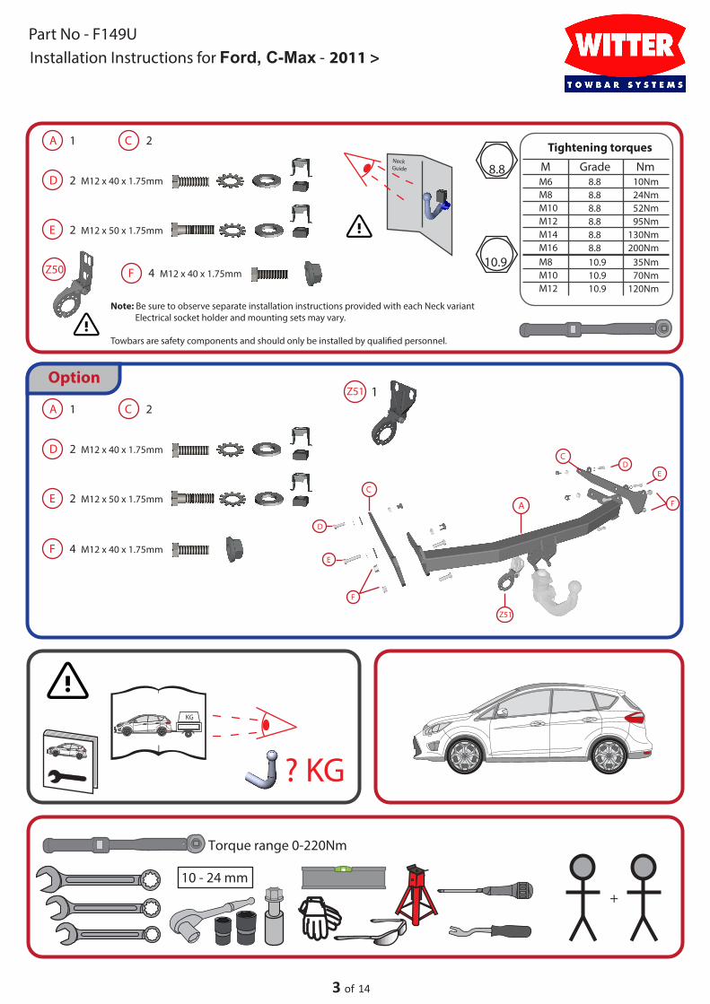
+10 - 24 mm
Torque range 0-220Nm
3 of 14
Installation Instructions for Ford, C-Max - 2011 >Part No - F149U
Note: Be sure to observe separate installation instructions provided with each Neck variant Electrical socket holder and mounting sets may vary.
Towbars are safety components and should only be installed by quali�ed personnel.
1Z51
Z50
Option
A
Z51
F
F
D
D
E
E
C
C
A 1 C 2
D 2 M12 x 40 x 1.75mm
E 2 M12 x 50 x 1.75mm
F 4 M12 x 40 x 1.75mm
A 1 C 2
D 2 M12 x 40 x 1.75mm
E 2 M12 x 50 x 1.75mm
F 4 M12 x 40 x 1.75mm
Tightening torques
Grade NmM8.8M6 10Nm
M8 8.8 24NmM10 8.8 52NmM12 8.8 95NmM14 8.8 130NmM16 8.8 200NmM8 10.9 35NmM10 10.9 70NmM12 10.9 120Nm
8.8
10.9
Neck Guide
4 of 14
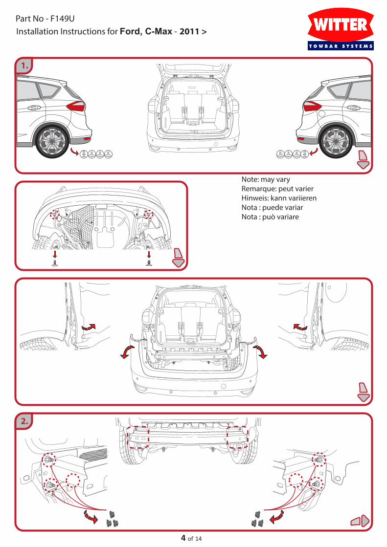
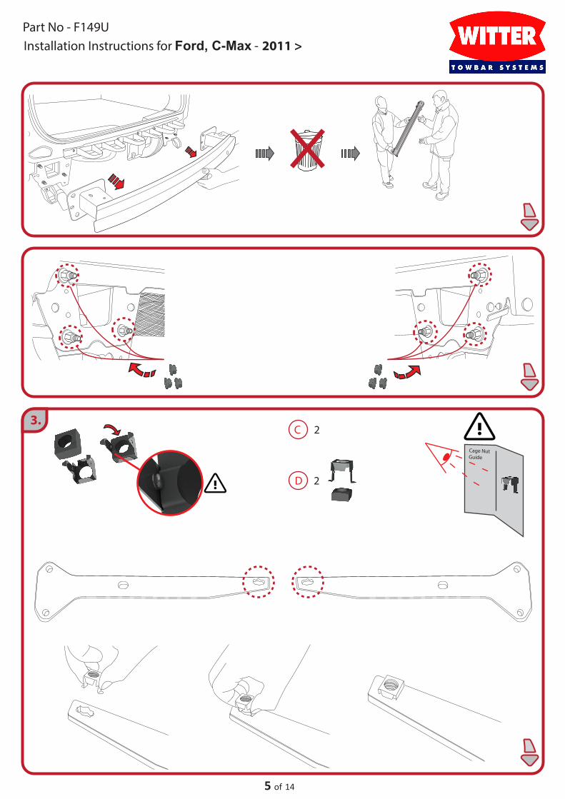
1.
2.
Installation Instructions for Ford, C-Max - 2011 >Part No - F149U
Note: may varyRemarque: peut varierHinweis: kann variierenNota : puede variarNota : può variare
5 of 14
3.
D 2
C 2
Cage Nut Guide
Installation Instructions for Ford, C-Max - 2011 >Part No - F149U
6 of 14
D 2 M12 x 40 x 1.75mm
Installation Instructions for Ford, C-Max - 2011 >Part No - F149U

7 of 14
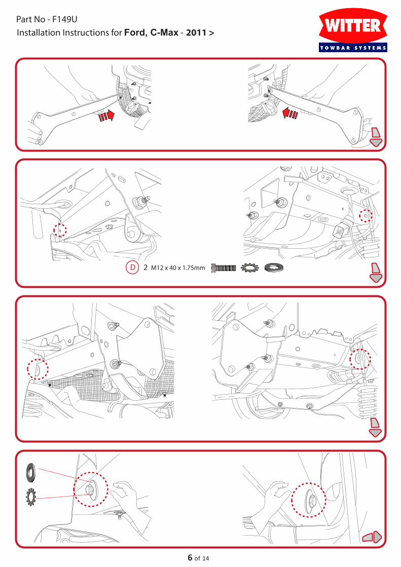
4.
E 2
Installation Instructions for Ford, C-Max - 2011 >Part No - F149U
Cage Nut Guide

8 of 14
E 2 M12 x 50 x 1.75mm
F 4 M12 x 40 x 1.75mm
Installation Instructions for Ford, C-Max - 2011 >Part No - F149U

9 of 14
M12 - 95Nm
FD E
M12 - 80NmM12 - 80Nm
DEF
M12 - 95Nm M12 - 80Nm M12 - 80Nm
7.
Installation Instructions for Ford, C-Max - 2011 >Part No - F149U

10 of 14
Instructions d'installation Ford, C-Max - 2011 >Part No - F149U
Important:
Veuillez-vous reporter aux données techniques du véhicule pour les limites de masse tractable et du poids admis sur la boule, lesquelles sont à observer. La capacité de l’attelage ne doit pas être dépassée.
ATTENTION:
Un Attelage est un élément de sécurité et s’il est installé et utilisé correctement. Il doit être installé par une personne quali�ée. Si il est installé ou utilisé incorrectement, il peut vous blesser, endommager votre véhicule ou les personnes/véhicule qui vous suivent.
Si une pièce de remplacement est installée, elle doit l’être sur une pièce d’origine intacte et par un professionnel.Toutes modi�cations de l’attelage sont interdites. Utiliser uniquement la visserie fournie de la correcte Classe pour l’installation de l’attelage.Le matériel fournis ne contient pas de pièces de remplacement. Si une pièce est manquante ou as une faute, merci d’informer Witter Towbars.
• L’installation de l’attelage doit être faite en accordance avec la directive 94/20/EG.• Le poids total permis pour le véhicule et la remorque doit être observé et ne doit pas être dépassé. La valeur testée de la D-value et S-Value ne doit pas être dépassé. Le rappel de capacité doit être �xé au véhicule le plus près possible de l’attelage. Elle peut être �xée dans le co�re si nécessaire.• La visserie doit être resserrée tous les 1000km de remorquage au couple de serrage recommandé.• La boule d’attelage doit toujours être légèrement huilée. Si un stabilisateur sur boule est utilisé, nettoyer la boule avant utilisation avant le remorquage comme indiqué dans le manuel d’utilisation du stabilisateur.• Le diamètre de la boule d’attelage doit être contrôlé régulièrement. Si le diamètre de la boule est de 49mm ou moins, la boule doit être remplacée pour des raisons de sécurité et ne peut plus être utilisé. La boule/attelage devrons être remplacé.• Si des points de montages doivent être percé, véri�er qu’il n’y ait pas de câble électrique ou boitier qui pourrais être endommagée. Les résidus de perçages doivent être nettoyés et les trous percés protéger contre la corrosion et la pénétration d’eau.• Le kit électrique doit être installé par une personne quali�é/professionnel installateur et la fonction de tous les feux doivent être contrôlé et fonctionnés correctement.
Lors du remorquage, les caractéristiques du véhicule sont modi�ées et une attention particulière par le conducteur est requise. Le remorquage a un impact sur le système de refroidissement du véhicule. Pour cette raison, il peut être nécessaire de modi�é le système de refroidissement du véhicule comme indiqué dans le manuel d’utilisation.Dans certains pays, la capacité de remorquage maximum doit être indiquée en Kg.La capacité indiqué est c’elle de l’attelage et n’indique pas la capacité du véhicule qui peut varier selon les modèles.
Les points de �xation sont homologués et approuver par le constructeur et ont été respectés.L’espace autour de la boule comme indiqué dans le paragraphe VII, �g. 30 de la directive 94/20/EG sont garanties.
Celons le paragraphe I, No. 5.10 de la directive 94/20/EG la certi�cation de l’installation de l’attelage par un expert ou un auditeur n’est plus nécessaire.
Cette notice de montage doit être ajoutée aux documents du véhicule.
Les directives des pays d’installation doivent êtres suivit en accordance avec les lois local. Sujet à modi�cations technique et de correction.Le fabricant n’est pas responsable pour les dommages causés par une installation ou utilisations incorrecte de ce produits, ainsi que pour toutes objections faites par une autorité compétente qui concernerait le code de la route.
Le fabricant n’est responsable que pour défaut de fabrication de l’attelage.

11 of 14
Einbauanleitung für Ford, C-Max - 2011 >Part No - F149U
WICHTIGE HINWEISE
Die vom Fahrzeughersteller fuer o.g. Modell maximal zugelassene Anhängelast und Stützlast ist den Fahrzeugpapierenbzw. der Bedienungsanweisung zu entnehmen. Für den Fahrbetrieb sind die Angaben der Fahrzeugherstellers bzgl.Anhängelast und Stützlast maßgebend, wobei die Werte der KmH nicht überschritten werden dürfen.
ACHTUNG
Die Anhängerkupplung (AHK) ist ein Sicherheitsteil und darf nur von Fachpersonal montiert warden.Sofern Ersatzteile erforderlich werden, dürfen auch diese nur von Fachpersonal am unbeschädigten Originalteil verbautwarden. Jegliche Änderung bzw. Umbauten an der AHK sind untersagt.Zur Montage der AHK dürfen nur die mitgelierfereten Verbindungselement der entsprechenden Festigkeitsklasseverwendet werden. Der Lieferumfang enthält keine durch den Benutzer austauschbaren Teil. Bei fehlenden odermangelhaften Teilen bitten wir um Mitteilung.
• Der Anbau der AHK an das Fahrzeug hat nach den Forderungen des Anhangs VII der Richtlinie 94/20/EG zu erfolgen.• Das zulässige Gespanngewicht (Fahrzeuggewicht + Anhängergewicht) dard nicht überschritten werden . Der geprüfte D-Wert und die geprüfte Stützlast der AHK dürfen nicht überschritten werden. Das Stützlastschild ist an gut sichtbarer Stelle in der Nähe der AHK am Fahrzeug aufzukleben. Auch die Innenseite des Ko�erraumes ist zulässig.• Alle Befestigungsschrauben der AHK nach ca. 1000 Anhänger-Km und bei jeder Fahrzeuginspektion gemäß den Anziehdrehmomenten nachziehen.• Der Kugelkopf ist stets leicht eingefettet einzusetzen. Bei Einsatz von Schwingungsdämpfern sin die Anweisungen des Herstellers zu beachten.• Der Durchmesser des Kugelkopfes ist von Zeit zu Zeit zu überprüfen. Sobald an einer beliebigen Stelle ein Durchmesser von 49mm erreicht ist, darf die AHK aus Sicherheitsgründen nicht mehr benutzt werde. Der Kugelkopf bzw. die AHK sind dann zu ersetzten.• Beim nachträglichen Anbringen von Bohrungen am Fahrzeug, ist vor dem Bohren zu prüfen, ob keine Fahrzeugleitungen bschädigt werden. Bohrspäne sind zu entfernen und alle gebohrten Löcher bzw. nachträglich angebrachte Ö�nungen sind gegen Korrosion und Eindringen von Wasser zu schützen. Die elektrische Anlage (Elektrosatz) gemäß StVZO montieren und die ordnungsgemäße Funktion der Beleuchtungseinrichtungen überprüfen.
Durch den Anhängerbetrieb weden die Fahreigenschaften des Fahrzeuges eingeschränkt und fordern vomFahrer erhöhte Aufmerksamkeit. Der Anhängerbetrieb stellt erhöhte Forderungen an das Kühlsystem.Eventuell erforderliche Umbaumaßnahmen am Kühlsystem sind bei der Vertragswerkstatt zu erfragen.In einigen Ländern ist die Angabe der zulässigen Anhängelast in kg am Fahrzeug vorgeschrieben.Die angegebene Anhängelast gilt nur für die Kupplungskugel mit Halterung und bezieht sich nicht auf dasKraftfahrzeug.
Die vom Fahrzeughersteller serienmäßig genehmigten Befestigungspunkte sind eingehalten. Der Freiraumsowie die Höhe der Kugelmitte nach Anhang VII, Abbildung 30 der Richtlinie 94/20/EG ist gewährleistet.Eine Abnahme des Anbaus der Anhängevorrichtung durch amtlich anerkannte Sachverständige oderPrüfer für den Kraftverkehr ist ensprechend den Festlegungen in Anhang I, Nr. 5.10 der Richtlinie 94/20/EG nichtmehr erforderlich.
Bei Änderungen der Anhängelast sind die Forderungen des §27 StVZO zu beachten.
Diese Montage- und Betriebsanleitung ist den Fahrzeugpapieren beizuordnen.
In EG- und nicht EG-Ländern ist nach den dort geltenden Bestimmungen zu verfahren.
Irrtümer und technische Änderungen vorbehalten!
12 of 14
Instrucciones de instalación para Ford, C-Max - 2011 >Part No - F149U
Importante:
Por favor consulte en el manual del propietario del vehículo la capacidad máxima carga remolcable y el valor de la carga vertical S en el punto de enganche. Al remolcar, estos valores suministrados por el fabricante deberán ser respetados en todo.
Advertencia:
La utilización de un remolque es segura si se instala y se usa correctamente. La instalación de un remolque la debe llevar a cabo personal cuali�cado y especializado. La instalación o el uso incorrecto de un remolque puede provocar danos personales y a vehículos.
Las piezas de repuesto del remolque también las debe instalar personal cuali�cado y especializado.Están prohibidos los cambios o manipulaciones en el remolque. Use siempre los anclajes correspondientes al remolque. Las piezas suministradas no son intercambiables. Si falta alguna pieza por favor comuníquelo a la compañía.
• La instalación de remolques se debe llevar a cabo de acuerdo a lo estipulado en el anexo VII de la directiva 94/20/EG del parlamento europeo y del consejo• El peso máximo combinado del vehículo mas el remolque no debe ser superado. El valor D admisible (kN) y el valor de la carga estática vertical S (kg) del remolque no deben ser superados. La placa de características del remolque se debe situar en un sitio visible cerca del remolque o en el interior del maletero.• Todos los anclajes se deben comprobar cada 1000km remolcados o en las revisiones del vehículo según los valores del par de apriete.• Se debe engrasar el cabezal del enganche. Si se usan sistemas de absorción de vibraciones consultar el manual del propietario.• El diámetro de la barra de remolque se debe comprobar regularmente. Si el diámetro es menor de 49mm en cualquier punto, la barra de remolque se debe reemplazar.• Asegurarse de no dañar ningún cableado electrónico al realizar agujeros de anclaje adicionales. Los agujeros extras se deben limpiar y proteger contra la corrosión y el oxido.• El kit eléctrico debe ser instalado por personal cuali�cado y especializado comprobando que todas las luces funcionan de manera correcta• Al remolcar, las características del coche quedan limitadas y el conductor deberá mantener un mayor nivel de atención y cuidado en la conducción. El remolcase tiene un mayor impacto en el sistema de refrigeración del coche. Es posible que el sistema de refrigeración se tenga que reforzar al instalar dispositivos de remolque.• En algunos países la carga máxima remolcable debe �gurar en kg. Esta capacidad de remolque se re�ere al paso máximo del remolque y su carga combinada y no tiene en cuenta el peso del vehículo.• Los anclajes has sido aprobados y estandarizados de acuerdo a las especi�ciones del fabricante del vehículo.• El espacio libre y la altura de las bolas de remolque deben cumplir con el apéndice VII, �gura 30 de la directriz europea 94/20/EG• Según el apéndice I, punto 5.10 de la directriz 94/20/EG, la certi�cación de una barra de remolque por un experto autorizado ya no es requisito imprescindible• Las instrucciones de montaje del sistema de remolque se deben conservar junto con la documentación del coche• Los sistemas de remolque están sujetos a la legislación local.• Esta información puede estar sujeta a errores y cambios técnicos• El fabricante no se responsabiliza de la instalación incorrecta o el mal uso de este producto, ni de ninguna reclamación hecha a las autoridades con respecto al código de circulación.• El fabricante solo se responsabiliza de los defectos de fabricación de la barra de remolque.

13 of 14
Compliance report/Informe de cumplimiento/Rapporto di conformitàcoupling device approved by the Directive 94/20/CEdispositivo de acoplamiento aprobado por la Directiva 94/20/CEdispositivo di attacco omologato dalla direttiva 94/20/CE
Motor vehicle /Automóvil / Autoveicolo Ford, C-Max - 2011 >
Type towing device / Tipo de dispositivo de remolque / Dispositivo di traino tipo F149U ( F149Q , F149S )
Class and type of coupling / Clase y tipo de acoplamiento / Classe e tipo di accoppiamento A50 - X
D value / valor D / Valore D: 10kN (Max) S Value / valor S / Valore S: 75 Kg (Maximum vertical load S)
Approval / aprobación / Omologazione: e11*94/20*8140*00 Towable Mass: see motor vehicle registration certi�cateMasa remolcable: ver motor de permiso de circulaciónMassa rimorchiabile: vedi carta di circolazione dell'autoveicoloTo verify the suitability of the towing device approved under Directive 94/20/CE, for installation on the car that you intend to install , �ll in the following form ( if necessary lower the trailer mass ) :Para veri�car la idoneidad del dispositivo de remolque homologado con arreglo al 94/20/CE, la instalación en el coche en el que se tiene la intención de proceder con la instalación ,rellene el siguiente formala (si es necesario rebaja la masa del remolque) : Per veri�care l’idoneitá del dispositivo di traino omologato a norma 94/20/CE, all’installazione sulla vettura su cui si intende procedere al montaggio, compilare la seguente formala ( se necessario declassare la massa rimorchiabile) :
Statement of Correct Installation Complete Form
? KGKG
D =T x C
T + Cx 0,00981 < 10kN
T = Overall mass Max . of drive (in kg) / Masa total máx . De unidad (kg) / Massa Complessiva Max. della motrice (kg)
The undersigned company declares to have mounted properly and in accordance with the requirements of both the vehicle manufacturer and that of the manufacturer of the mechanical coupling device.
Type / Tipo
The coupling device described above has been installed on your motor vehicle. / El dispositivo de acoplamiento descrito anteriormente ha sido instalado en su vehículo de motor. / Il dispositivo di accoppiamento sopra descritto è stato installato sul vostro veicolo a motore.
……………………………………………………………………………
Model / Modelo / Modello
Number Plate / Número de placa / Targa
Date / Fecha / Data
Signature and stamp
We/ I declare that information regarding the use and maintenance of the device, has been explained to the user/customer.
……………………………………………………………………………
……………………………………………………………………………
……………………………………………………………………………
……………………………………………………………………………
Part number - F149U Installation Instructions Ford, C-Max - 2011 >Instrucciones de instalación paraIstruzioni per l'installazione
WITTER TOWBARS, DROME ROAD, DEESIDE INDUSTRIAL PARK, DEESIDE, FLINTSHIRE, CH5 2NY.
Telephone: (01244) 284500 Fax: (01244) 284577 VAT Registration No. GB 310 3737 00
C = Towable Mass Max . of drive (in kg) / Masa remolcable máxima . Por unidad / Massa Rimorchiabile Max. della motrice
Declaración de instalación correctaDichiarazione Corretto Montaggio
Forma completaforma completa
La empresa �rmante declara tener Montado adecuadamente y de acuerdo con los requisitos tanto el fabricante del vehículola del fabricante de la misma el siguiente dispositivo de acoplamiento mecánicoLa sottoscritta ditta dichiara di aver montado in maniera corretta ed in conformit alle prescrizioni sia del costruttore del veicolo che del costruttore del dispositivo stesso il seguente dispositivo di attacco meccanico
También declara de informar al usuario del vehículo en el uso y el mantenimiento del dispositivo. Si dichiara inoltre de aver informato l'utente del veicolo sull'uso e manutenzione del dispositivo stesso.
Firma y estampaFirma e Timbro
14 of 14
Important:
Please refer to the manufacturers handbook of the vehicle regarding the maximum towing capacity and S-value. When towing the values of the vehicle manufacturer are to be followed strictly; the values of the towbar must however not be exceeded.
Warning:
The towbar is a safety component IF �tted & used correctly. It must be installed by quali�ed personnel/trained �tter. If it is �tted or used incorrectly it can cause damage to you, your vehicle and anyone driving behind you.
If replacement parts are required they must also be �tted to the intact original part by a trained �tter. Any changes or manipulations to the towbar are forbidden. Only use the �xing provided with the correct grade to �t the towbar. The materials provided do not contain any interchangeable parts. Should any parts be missing or faulty please inform Witter Towbars accordingly.
• The �tting of the towbar needs to be carried out according to appendix VII of the guidelines 94/20/EG.• The overall weight allowed for the vehicle plus the object to be towed (e.g. caravan) must not be exceed. The tested D-value and S-Value of the towbar must not be exceeded. The S-Value plate needs to be attached to the car in a highly visible position close to the towbar. The inside of the boot is also allowed.• Re-tighten all �xings after every 1000km of towing or when servicing the car according to the torque values.• The towball is always to be used slightly oily. If shock-mounts (vibration absorbers?) are used refer to the manufacturer’s handbook.• The diameter of the towball needs to be checked from time to time. Should the diameter reach 49mm at any point of the towball it needs to be replaced due to safety reasons and cannot be used anymore. The towball and/or the towbar will need to be replaced.• If additional mounting holes are drilled it needs to be checked that no electronic wires will be damaged. Drilling chips are to be removed and all holes drilled need to be protected against corrosion and water damage. • The electric kit needs to be installed by quali�ed personnel/trained �tter and it needs to be checked that all lights are working correctly.
Due to towing the characteristics of the vehicle are limited and a higher level of attention and care is required by the driver. Towing has an increased impact on the cooling system of the vehicle. Potential changes to the cooling system need to be requested from the local �tter/garage. In some countries the maximum towing capacity of the vehicle needs to be stated (in kg). The stated towing capacity only refers to the towball with housing and does not refer to the vehicle.
Mounting holes approved and standardized by the vehicle manufacturer have been complied with.The free space as well as the towball middle according to appendix VII, �g. 30 of guideline 94/20/EG are guaranteed.
According to appendix I, No. 5.10 of the guideline 94/20/EG the certi�cation of the towbar by an authorized expert or auditor is not required anymore.
These �tting instructions need to be added to the car documention.
Local guidelines of other EG and non-EG countries need to be followed according to the local law.
Subject to errors and technical changes.
The manufacturer is not responsible for damage caused by improper �tting or use of this product, nor for any objection made by the competent authorities with regard to the highway code.
The manufacturer shall only be responsible for manufacturing defects in the towbar.
Installation Instructions for Ford, C-Max - 2011 >Part No - F149U