installation instructions for dft cable sets - emerson dft cable guide and dft cable installation...
TRANSCRIPT
Installation Instructionsfor DFT cable sets
ElEctric Shock/FirE hazardRead the following waRnings and instRuctions pRovided befoRe attempting installation. failuRe to do so could Result in cable failuRe, impRopeR system opeRation, pRopeRty damage, bodily injuRy oR death. failuRe to follow the waRnings and instRuctions will also void the waRRanty.
1. electrical inspection may be required before, during and/or after installation of the warm tiles system. contact your local electrical inspection authority for more information befoRe beginning installation.
2. do not energize coiled heating cable – the cable will overheat. 3. heating cable must not touch, cross or overlap itself at any point and cable must not be closer than 1½" to adjacent cable. this could
cause the cable to overheat. 4. Donotinstallheatingcableunderanytypeofnailed-downorstapledflooring.Floornailsandstaplescandamagethecableresultingin
exposed live electrical parts and/or result in the cable overheating.5. DonotdrillorotherwisecutintofloorsthathaveWarmTilescables–thiscouldresultincontactwithliveelectricalpartsorcould
damage the cable causing it to overheat.6. do not use the warm tiles system for other types of applications, such as snow melting or roof de-icing – the cable is not rated for
these types of applications. contact easyheat for professional advice for recommendations on other products for these applications.7. Donotalterthelengthoftheheatingcabletosuitafloorarealargerorsmallerthantherecommendedrangeforthatcable.Onlythe
cold lead (black cable connected to the heating cable) may be cut to suit hook-up in the electrical connection box (ecb). to facilitate productidentificationandinspection,ensurethataminimum150mm(6”)ofcoldleadwiththefactoryidentificationtagisretainedwithin the junction box.
8. the entire heating cable, the cold lead splice and tail splice must be embedded in a cement-based underlayment. the heating cable could overheat if not entirely embedded in cement-based underlayment. never coil unused cable and place in a wall cavity – the cable will overheat.
9. use caution when trowelling mortar/cement over heating cables – trowels can become sharp and may cut heating cable which could damage the ground braid, electrical insulation and/or expose live heating element.
10.Cablesmustbeatleast0.25”belowfloorsurface;ifcablesareexposed,theycouldbedamagedwhichwouldexposelivepartsand/orcause the cable to overheat.
11.Wheninstallingcableinfloorsthatareroutinelyexpectedtobewet,suchastileshowers,awaterproofingmembranemustbeinstalledabove the cables to keep them dry. the cables are not rated for wet locations, and water could seep into the cable.
12.Itisrecommendedthatthecircuitsupplyingtheheatingcablehavegroundfaultprotection;thisismandatorybyelectricalcodeforsomeapplicationsinmanyregions.Incaseswherethefloorisroutinelyexpectedtobewet,suchastiledshowers,aGroundFaultCircuitinterrupter (gfci), or equivalent, must be installed. additionally, per us national electrical code, installation in some rooms, such as bathrooms and kitchens, may require that this product be installed on a circuit protected by a separate ground fault circuit interrupter (GFCI).Consultyourlocalelectricaland/orbuildingauthoritiestodeterminethespecificgroundfaultrequirementsforyourapplicationprior to installation. if you are unsure that your circuit has ground fault protection, consult an electrician.
13. if the system is connected to a ground fault protection circuit that trips during normal operation, and cannot be reset, there is likely a fault in the heating cable. no attempt should be made to re-energize the system. under no circumstances should the ground fault protection be bypassed – contact easyheat for advice.
14.Donotbendtheheatingcableatrightangles–thiscoulddamagetheelectricalinsulation;minimumbendingradiusis¾."15.Donotusestaplestoaffixcoldlead,heatingcablesorthermostatsensorwire,asthiscouldpuncturetheheatingcableresultingin
short circuit or exposed live electrical parts. use only the cable strapping provided with the system, and only staple according to the instructions.
16.Donotplacemorethansixconsecutive/adjacentrunsofheatingcableat1½"spacing;doingsowillcausethefloorareatooverheat.17. only connect cables to the rated voltage – do not use higher voltages as the increased current will cause cable to overheat.18. ensure that all electrical control devices, such as thermostats, are properly rated for the heating cable load. do not overload these
devices as they will overheat or otherwise fail.19. ensure that copper grounding braid material is directly connected to electrical ground – do not cut the ground braid. if the ground braid
is not connected to ground, the heating cable will not be grounded and may not provide the required protection against short circuits or electrical shocks.
20.These instructions have been prepared for use with standard NorthAmerican building construction practices. If your buildingconstruction differs, consult an appropriate electrical professional.
WARNING!
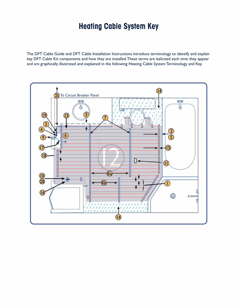
Heating Cable System Key
the dft cable guide and dft cable installation instructions introduce terminology to identify and explain key dft cable Kit components and how they are installed. these terms are italicized each time they appear and are graphically illustrated and explained in the following heating cable system terminology and Key.
{
{
to circuit breaker panel
2
14
14
5
15
11
20
16
46
8a
8b 110
18
17
3
19
9
13 7
21
5
{
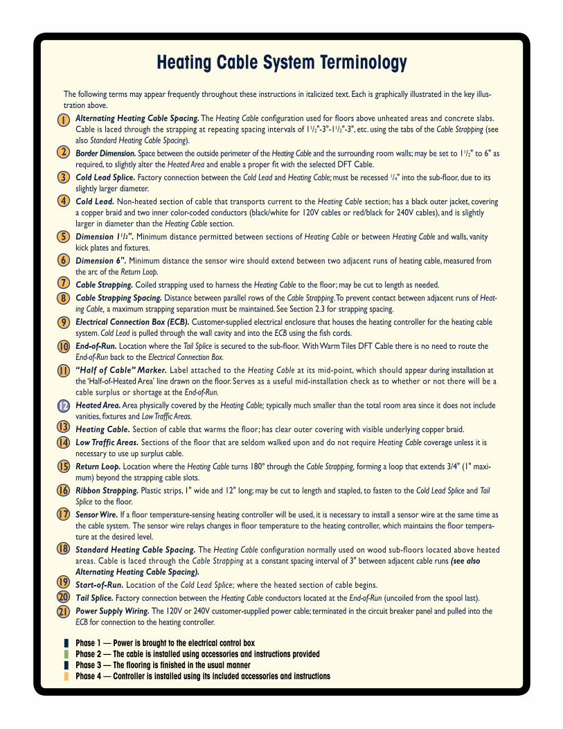
Heating Cable System Terminologythe following terms may appear frequently throughout these instructions in italicized text. each is graphically illustrated in the key illus-tration above. Alternating Heating Cable Spacing. the Heating Cableconfigurationusedforfloorsaboveunheatedareasandconcreteslabs.
cable is laced through the strapping at repeating spacing intervals of 11/2"-3"-11/2"-3", etc. using the tabs of the Cable Strapping (see also Standard Heating Cable Spacing).
Border Dimension. space between the outside perimeter of the Heating Cableandthesurroundingroomwalls;maybesetto11/2" to 6" as required, to slightly alter the Heated AreaandenableaproperfitwiththeselectedDFTCable.
Cold Lead Splice. factory connection between the Cold Lead and Heating Cable; must be recessed 1/4"intothesub-floor,duetoitsslightly larger diameter.
Cold Lead. non-heated section of cable that transports current to the Heating Cablesection;hasablackouterjacket,coveringacopperbraidandtwoinnercolor-codedconductors(black/whitefor120Vcablesorred/blackfor240Vcables),andisslightlylarger in diameter than the Heating Cable section.
Dimension 11/2". minimum distance permitted between sections of Heating Cable or between Heating Cable and walls, vanity kickplatesandfixtures.
Dimension 6". minimum distance the sensor wire should extend between two adjacent runs of heating cable, measured from the arc of the Return Loop.
Cable Strapping. coiled strapping used to harness the Heating Cabletothefloor;maybecuttolengthasneeded. Cable Strapping Spacing. distance between parallel rows of the Cable Strapping. to prevent contact between adjacent runs of Heat‑
ing Cable, a maximum strapping separation must be maintained. see section 2.3 for strapping spacing. Electrical Connection Box (ECB). customer-supplied electrical enclosure that houses the heating controller for the heating cable
system. Cold Lead is pulled through the wall cavity and into the ECBusingthefishcords. End‑of‑Run. location where the Tail Spliceissecuredtothesub-floor.WithWarmTilesDFTCablethereisnoneedtoroutethe
End‑of‑Run back to the Electrical Connection Box. “Half of Cable” Marker. label attached to the Heating Cable at its mid-point, which should appear during installation at
the‘Half-of-HeatedArea’linedrawnonthefloor.Servesasausefulmid-installationcheckastowhetherornottherewillbeacable surplus or shortage at the End‑of‑Run.
Heated Area. area physically covered by the Heating Cable; typically much smaller than the total room area since it does not include vanities,fixturesandLow Traffic Areas.
Heating Cable.Sectionofcablethatwarmsthefloor;hasclearoutercoveringwithvisibleunderlyingcopperbraid. Low Traffic Areas. sections of the floor that are seldom walked upon and do not require Heating Cable coverage unless it is
necessary to use up surplus cable. Return Loop. location where the Heating Cableturns180ºthroughtheCable Strapping, forming a loop that extends 3/4" (1" maxi-
mum) beyond the strapping cable slots. Ribbon Strapping.Plasticstrips,1"wideand12"long;maybecuttolengthandstapled,tofastentotheCold Lead Splice and Tail
Splicetothefloor. Sensor Wire.Ifafloortemperature-sensingheatingcontrollerwillbeused,itisnecessarytoinstallasensorwireatthesametimeas
thecablesystem.Thesensorwirerelayschangesinfloortemperaturetotheheatingcontroller,whichmaintainsthefloortempera-ture at the desired level.
Standard Heating Cable Spacing. the Heating Cable configuration normally used on wood sub-floors located above heated areas. cable is laced through the Cable Strapping at a constant spacing interval of 3" between adjacent cable runs (see also Alternating Heating Cable Spacing).
Start‑of‑Run. location of the Cold Lead Splice;wheretheheatedsectionofcablebegins. Tail Splice. factory connection between the Heating Cable conductors located at the End‑of‑Run (uncoiled from the spool last). Power Supply Wiring.The120Vor240Vcustomer-suppliedpowercable;terminatedinthecircuitbreakerpanelandpulledintothe
ECB for connection to the heating controller.
z Phase 1 — Power is brought to the electrical control boxz Phase 2 — The cable is installed using accessories and instructions providedz Phase 3 — The flooring is finished in the usual mannerz Phase 4 — Controller is installed using its included accessories and instructions
1
3
4
5
6
78
2
9
10
11
12
1314
15
16
17
18
2019
21
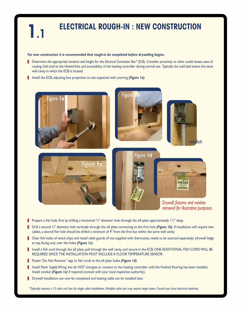
1.1 eleCTRICAl RouGH-IN : NeW CoNSTRuCTIoN
z determine the appropriate location and height for the Electrical Connection Box* (ECB). consider proximity to other outlet boxes, ease of routing Cold Lead to the Heated Area, and accessibility of the heating controller during normal use. typically the cold lead enters the same wall cavity in which the ecb is located.
z install the ecb, adjusting box projection to suit expected wall covering (Figure 1a).
For new construction it is recommended that rough‑in be completed before drywalling begins.
Figure 1aFigure 1b
Figure 1cFigure 1d
conduit
Drywall, fixtures and vanities removed for illustrative purposes.
z Prepareafishhole,firstbydrillingahorizontal¾"diameterholethroughthesillplateapproximately1½"deep.
z Drillasecond¾"diameterholeverticallythroughthesillplateconnectingtothefirsthole(Figure 1b). if installation will require two cables,asecondfishholeshouldbedrilledaminimumof4"fromthefirstbutwithinthesamewallcavity.
z Clearfishholesofwoodchipsandinstallcableguards(ifnotsuppliedwiththermostat,needstobesourcedseparately)(drywallledgeat top, facing out) over the holes (Figure 1c).
z Installafishcordthroughthesillplate,pullthroughthewallcavity,andsecureintheECB.ONEADDITIONALFISHCORDWILLBEReQuiRed since the installation must include a flooR tempeRatuRe sensoR.
z Fasten“DoNotRemove”tagstofishcordsatthesillplateholes(Figure 1d).
z install Power Supply Wiring,butdoNOTenergizeorconnecttotheheatingcontrolleruntilthefinishedflooringhasbeeninstalled.install conduit (Figure 1e) if required (consult with your local inspection authority).
z drywall installation can now be completed and heating cable can be installed later.
* Typically requires a 15 cubic inch box for single cable installations. Multiple cable sets may require larger boxes. Consult your local electrical authority.
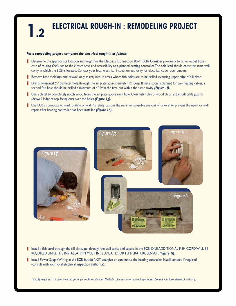
1.2 eleCTRICAl RouGH-IN : RemodelING PRojeCT
z determine the appropriate location and height for the electrical connection box* (ECB). consider proximity to other outlet boxes, ease of routing Cold Lead to the Heated Area, and accessibility to a planned heating controller. the cold lead should enter the same wall cavity in which the ecb is located. contact your local electrical inspection authority for electrical code requirements.
z Removebasemoldings,anddrywallonlyasrequired,inareaswherefishholesaretobedrilled,exposingupperedgeofsillplate.
z Drillahorizontal¾"diameterholethroughthesillplateapproximately1½"deep.Ifinstallationisplannedfortwoheatingcables,asecondfishholeshouldbedrilledaminimumof4"fromthefirst,butwithinthesamecavity(Figure 1f).
z Useachiseltocompletelynotchwoodfromthesillplateaboveeachhole.Clearfishholesofwoodchipsandinstallcableguards(drywall ledge at top, facing out) over the holes (Figure 1g).
z use ecb as template to mark outline on wall. carefully cut out the minimum possible amount of drywall to prevent the need for wall repair after heating controller has been installed (Figure 1h).
For a remodeling project, complete the electrical rough‑in as follows:
z Installafishcordthroughthesillplate,pullthroughthewallcavityandsecureintheECB.ONEADDITIONALFISHCORDWILLBEReQuiRed since the installation must include a flooR tempeRatuRe sensoR (Figure 1i).
z install power supply wiring in the ecb, but do not energize or connect to the heating controller. install conduit, if required (consult with your local electrical inspection authority).
* Typically requires a 15 cubic inch box for single cable installations. Multiple cable sets may require larger boxes. Consult your local electrical authority.
Figure1f
Figure1g Figure1h
Figure1i
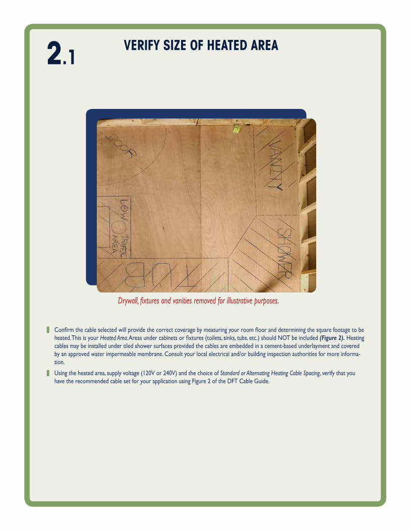
veRIfy SIze of HeATed AReA
z Confirmthecableselectedwillprovidethecorrectcoveragebymeasuringyourroomflooranddeterminingthesquarefootagetobeheated. this is your Heated Area.Areasundercabinetsorfixtures(toilets,sinks,tubs,etc.)shouldNOTbeincluded(Figure 2). heating cables may be installed under tiled shower surfaces provided the cables are embedded in a cement-based underlayment and covered by an approved water impermeable membrane. consult your local electrical and/or building inspection authorities for more informa-tion.
z Usingtheheatedarea,supplyvoltage(120Vor240V)andthechoiceofStandard or Alternating Heating Cable Spacing, verify that you have the recommended cable set for your application using figure 2 of the dft cable guide.
Drywall, fixtures and vanities removed for illustrative purposes.
2.1
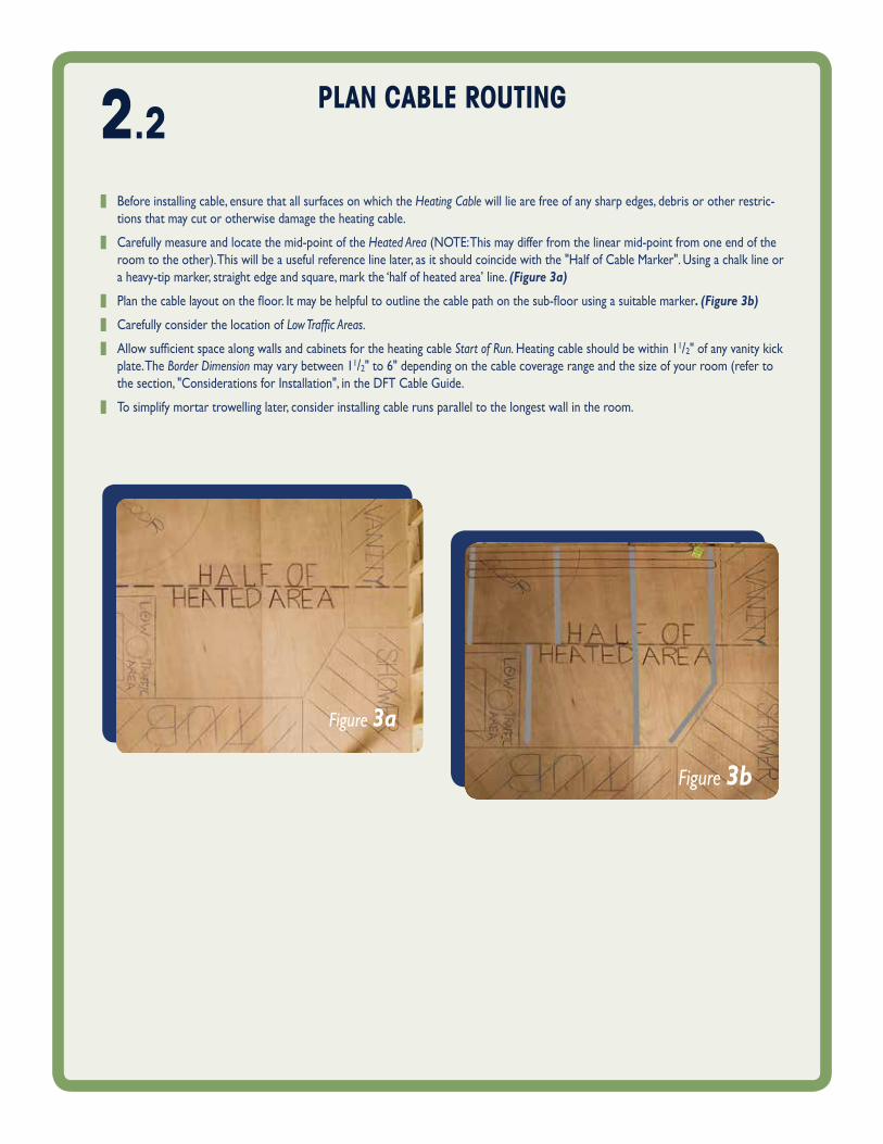
2.2 PlAN CAble RouTING
z before installing cable, ensure that all surfaces on which the Heating Cable will lie are free of any sharp edges, debris or other restric-tions that may cut or otherwise damage the heating cable.
z carefully measure and locate the mid-point of the Heated Area (note: this may differ from the linear mid-point from one end of the room to the other). this will be a useful reference line later, as it should coincide with the "half of cable marker". using a chalk line or a heavy-tip marker, straight edge and square, mark the ‘half of heated area’ line. (Figure 3a)
z Planthecablelayoutonthefloor.Itmaybehelpfultooutlinethecablepathonthesub-floorusingasuitablemarker. (Figure 3b)
z carefully consider the location of Low Traffic Areas.
z AllowsufficientspacealongwallsandcabinetsfortheheatingcableStart of Run. heating cable should be within 11/2" of any vanity kick plate. the Border Dimension may vary between 11/2" to 6" depending on the cable coverage range and the size of your room (refer to the section, "considerations for installation", in the dft cable guide.
z to simplify mortar trowelling later, consider installing cable runs parallel to the longest wall in the room.
Figure 3b
Figure 3a
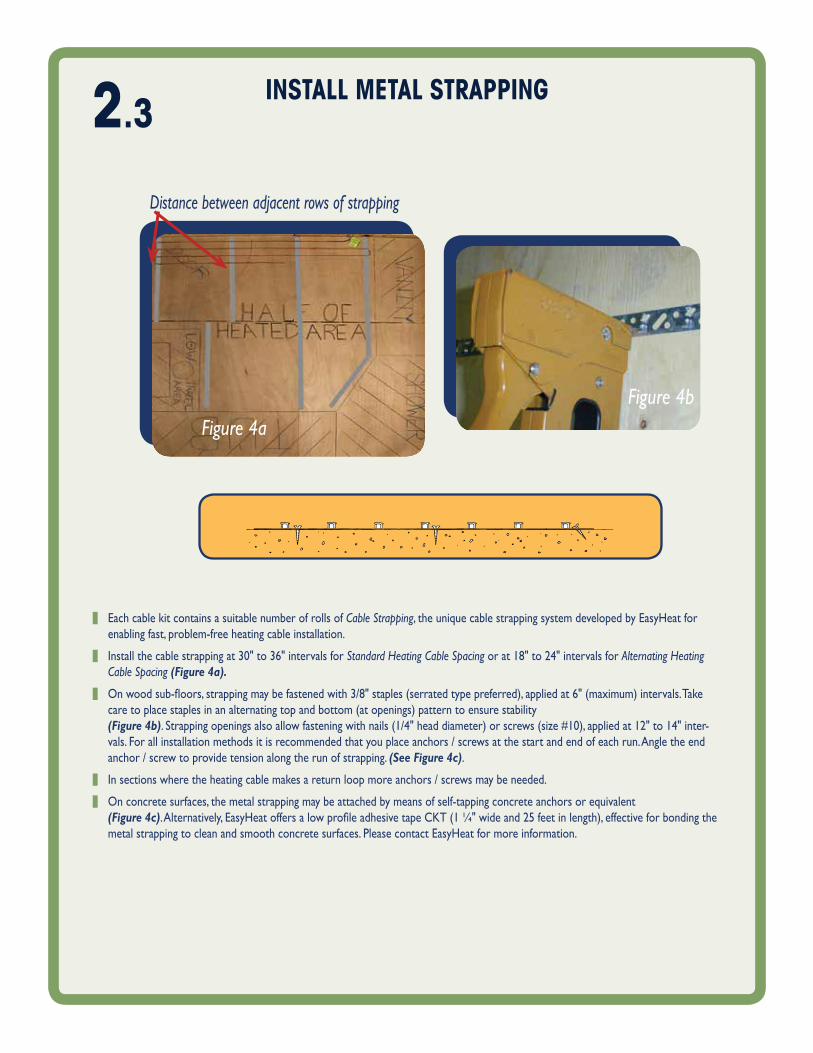
Figure 4bFigure 4a
Distance between adjacent rows of strapping
INSTAll meTAl STRAPPING
z each cable kit contains a suitable number of rolls of Cable Strapping, the unique cable strapping system developed by easyheat for enabling fast, problem-free heating cable installation.
z Installthecablestrappingat30"to36"intervalsforStandard Heating Cable Spacing or at 18" to 24" intervals for Alternating Heating Cable Spacing (Figure 4a).
z Onwoodsub-floors,strappingmaybefastenedwith3/8"staples(serratedtypepreferred),appliedat6"(maximum)intervals.Takecare to place staples in an alternating top and bottom (at openings) pattern to ensure stability (Figure 4b).Strappingopeningsalsoallowfasteningwithnails(1/4"headdiameter)orscrews(size#10),appliedat12"to14"inter-vals. for all installation methods it is recommended that you place anchors / screws at the start and end of each run. angle the end anchor / screw to provide tension along the run of strapping. (See Figure 4c).
z in sections where the heating cable makes a return loop more anchors / screws may be needed.
z on concrete surfaces, the metal strapping may be attached by means of self-tapping concrete anchors or equivalent (Figure 4c).Alternatively,EasyHeatoffersalowprofileadhesivetapeCKT(1¼"wideand25feetinlength),effectiveforbondingthemetal strapping to clean and smooth concrete surfaces. please contact easyheat for more information.
2.3
veRIfy ReSISTANCe of HeATING CAble ANd SeNSoR WIRe
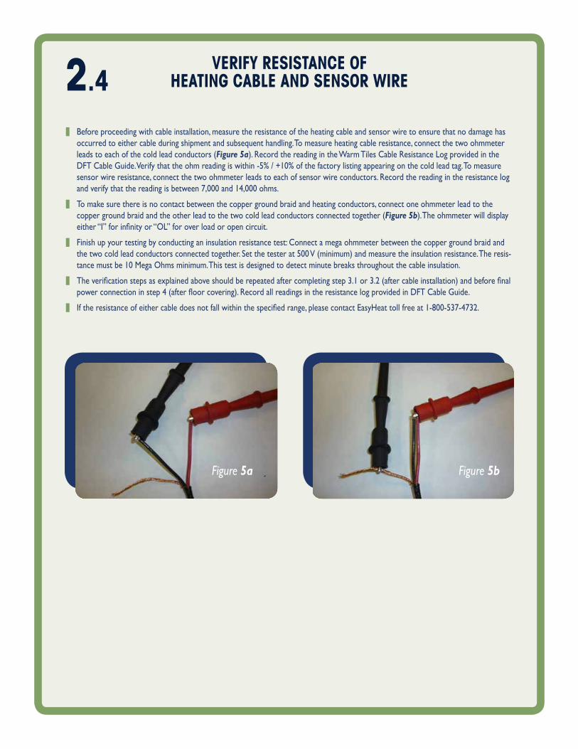
z before proceeding with cable installation, measure the resistance of the heating cable and sensor wire to ensure that no damage has occurred to either cable during shipment and subsequent handling. to measure heating cable resistance, connect the two ohmmeter leads to each of the cold lead conductors (Figure 5a). Record the reading in the warm tiles cable Resistance log provided in the DFTCableGuide.Verifythattheohmreadingiswithin-5%/+10%ofthefactorylistingappearingonthecoldleadtag.Tomeasuresensor wire resistance, connect the two ohmmeter leads to each of sensor wire conductors. Record the reading in the resistance log andverifythatthereadingisbetween7,000and14,000ohms.
z to make sure there is no contact between the copper ground braid and heating conductors, connect one ohmmeter lead to the copper ground braid and the other lead to the two cold lead conductors connected together (Figure 5b). the ohmmeter will display either“I”forinfinityor“OL”foroverloadoropencircuit.
z finish up your testing by conducting an insulation resistance test: connect a mega ohmmeter between the copper ground braid and thetwocoldleadconductorsconnectedtogether.Setthetesterat500V(minimum)andmeasuretheinsulationresistance.Theresis-tancemustbe10MegaOhmsminimum.Thistestisdesignedtodetectminutebreaksthroughoutthecableinsulation.
z Theverificationstepsasexplainedaboveshouldberepeatedaftercompletingstep3.1or3.2(aftercableinstallation)andbeforefinalpowerconnectioninstep4(afterfloorcovering).RecordallreadingsintheresistancelogprovidedinDFTCableGuide.
z Iftheresistanceofeithercabledoesnotfallwithinthespecifiedrange,pleasecontactEasyHeattollfreeat1-800-537-4732.
2.4
Figure 5a Figure 5b
Pull Cold leAd ANd SeNSoR WIRe INTo eCb; SeCuRe THe Cold leAd SPlICe2.5
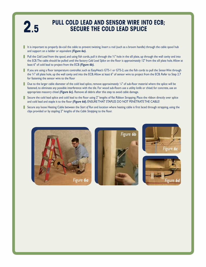
z it is important to properly de-coil the cable to prevent twisting. insert a rod (such as a broom handle) through the cable spool hub and support on a ladder or equivalent (Figure 6a).
z pull the Cold Leadfromthespool,andusingfishcords,pullitthroughthe¾"holeinthesillplate,upthroughthewallcavityandintothe ECB. the cable should be pulled until the factory Cold Lead Spliceonthefloorisapproximately12"fromthesillplatehole.Allowatleast 6" of cold lead to project from the ecb (Figure 6b).
z Ifyouareusingafloortemperaturecontroller,suchasEasyHeat’sGTS-1orGTS-2,usethefishcordstopulltheSensor Wire through the¾"sillplatehole,upthewallcavityandintotheECB.Allowatleast6"ofsensorwiretoprojectfromtheECB.RefertoStep2.7forfasteningthesensorwiretothefloor
z Duetothelargercablediameterofthecoldleadsplice,removeapproximately¼"ofsub-floormaterialwherethesplicewillbefastened,toeliminateanypossibleinterferencewiththetile.Forwoodsub-floorsuseautilityknifeorchisel;forconcrete,useanappropriate masonry chisel (Figure 6c). Remove all debris after this step to avoid cable damage.
z Securethecoldleadspliceandcoldleadtothefloorusing2"lengthsofflatRibbonStrapping.Placetheribbondirectlyoverspliceandcoldleadandstapleittothefloor(Figure 6d). ensuRe that staples do not penetRate the cable!
z secure any loose heating cable between the Start of Runandlocationwhereheatingcableisfirstlacedthroughstrapping,usingtheclips provided or by stapling 2" lengths of the Cable Strappingtothefloor.
Figure 6b
Figure 6c
Figure 6dFigure 6a
2.6 lACe CAble THRouGH STRAPPING
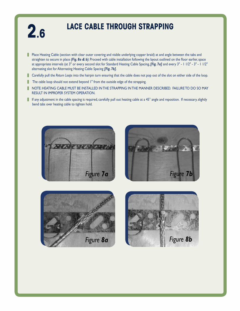
z place heating cable (section with clear outer covering and visible underlying copper braid) at and angle between the tabs and straighten to secure in place (Fig. 8a & b).Proceedwithcableinstallationfollowingthelayoutoutlinedonthefloorearlier,spaceat appropriate intervals (at 3" or every second slot for standard heating cable spacing, [Fig. 7a] and every 3" - 1 1/2" - 3" - 1 1/2" alternating slot for alternating heating cable spacing [Fig. 7b].
z carefully pull the Return Loops into the hairpin turn ensuring that the cable does not pop out of the slot on either side of the loop.
z the cable loop should not extend beyond 1" from the outside edge of the strapping.
z note: heating cable must be installed in the stRapping in the manneR descRibed. failuRe to do so may Result in impRopeR system opeRation.
z if any adjustment in the cable spacing is required, carefully pull out heating cable at a 45° angle and reposition. if necessary, slightly bend tabs over heating cable to tighten hold.
Figure 8bFigure 8a
Figure 7a Figure 7b
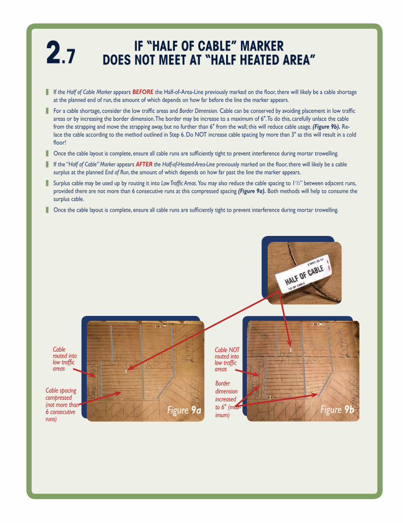
Figure 9bFigure 9a
z if the Half of Cable Marker appears BEFOREtheHalf-of-Area-Linepreviouslymarkedonthefloor,therewilllikelybeacableshortageat the planned end of run, the amount of which depends on how far before the line the marker appears.
z Foracableshortage,considerthelowtrafficareasandBorder Dimension.Cablecanbeconservedbyavoidingplacementinlowtrafficareas or by increasing the border dimension. the border may be increase to a maximum of 6". to do this, carefully unlace the cable fromthestrappingandmovethestrappingaway,butnofurtherthan6"fromthewall;thiswillreducecableusage.(Figure 9b). Re-lace the cable according to the method outlined in step 6. do not increase cable spacing by more than 3" as this will result in a cold floor!
z Oncethecablelayoutiscomplete,ensureallcablerunsaresufficientlytighttopreventinterferenceduringmortartrowelling.
z if the “Half of Cable” Marker appears AFTER the Half-of-Heated-Area-Linepreviouslymarkedonthefloor,therewilllikelybeacablesurplus at the planned End of Run, the amount of which depends on how far past the line the marker appears.
z surplus cable may be used up by routing it into Low Traffic Areas. you may also reduce the cable spacing to 11/2”betweenadjacentruns,provided there are not more than 6 consecutive runs at this compressed spacing (Figure 9a). both methods will help to consume the surplus cable.
z Oncethecablelayoutiscomplete,ensureallcablerunsaresufficientlytighttopreventinterferenceduringmortartrowelling.
Cable routed into low traffic areas
Cable spacing compressed (not more than 6 consecutive runs)
Border dimension increased to 6" (max‑imum)
Cable NOT routed into low traffic areas
2.7 If “HAlf of CAble” mARKeRdoeS NoT meeT AT “HAlf HeATed AReA”
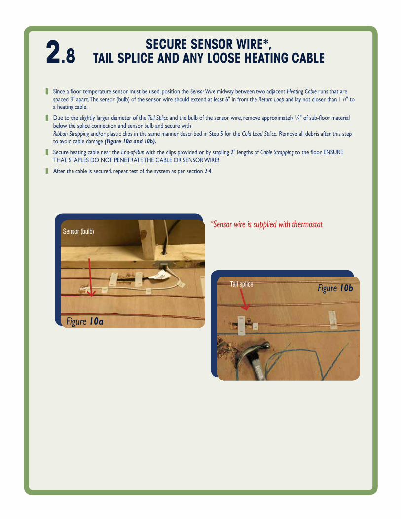
Figure 10a
Figure 10b
Sensor (bulb)
Tail splice
SeCuRe SeNSoR WIRe*, TAIl SPlICe ANd ANy looSe HeATING CAble
z Sinceafloortemperaturesensormustbeused,positiontheSensor Wire midway between two adjacent Heating Cable runs that are spaced 3" apart. the sensor (bulb) of the sensor wire should extend at least 6" in from the Return Loop and lay not closer than 11/2" to a heating cable.
z due to the slightly larger diameter of the Tail Spliceandthebulbofthesensorwire,removeapproximately¼"ofsub-floormaterialbelow the splice connection and sensor bulb and secure with Ribbon Strapping and/or plastic clips in the same manner described in step 5 for the Cold Lead Splice. Remove all debris after this step to avoid cable damage (Figure 10a and 10b).
z secure heating cable near the End‑of‑Run with the clips provided or by stapling 2" lengths of Cable Strappingtothefloor.ENSUREthat staples do not penetRate the cable oR sensoR wiRe!
z after the cable is secured, repeat test of the system as per section 2.4.
*Sensor wire is supplied with thermostat
2.8

3.1 APPly SCRATCH CoAT of moRTARANd ComPleTe flooRING
TIlez Oncethecableshavebeeninstalledonthefloor,applya‘scratchcoatofcement-basedmortaruniformlyovertheentirefloorarea,
such that the heating cables are completely embedded. self-leveling cement-based mortar compounds may be most appropriate for this procedure,butconsultwithyourflooringsupplierforadvice.
z follow the compound manufacturer’s instructions for preparing the mix.
z Usingastraightedgetrowel,covertheentirefloorarea,includingareaswithoutcable,tomaintainauniformfloorheight.Onlyapplymortar in the direction of the straight cable runs to minimize lateral movement between adjacent cable runs (Figure 11a).
z after the mortar is dry, repeat test of the system as per 2.4. the tile can be set in the usual manner. floors with heating cables installed are typically 3/16" higher than those without heating cables. Figures 11a and 11b illustrateeachofthesub-layersofafinishedfloorwhentileandlaminate/engineeredwoodareusedasthefloorfinishingmaterials.
Figure 11a
Heating Cable
Tile Flooring Trowelled MortarScratch Coat over Cable
Figure 11b
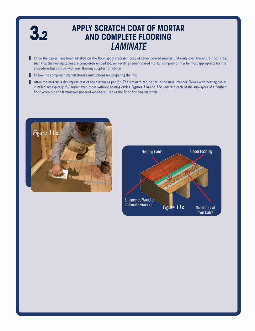
z Oncethecableshavebeeninstalledonthefloor,applya‘scratchcoatofcement-basedmortaruniformlyovertheentirefloorarea,such that the heating cables are completely embedded. self-leveling cement-based mortar compounds may be most appropriate for this procedure,butconsultwithyourflooringsupplierforadvice.
z follow the compound manufacturer’s instructions for preparing the mix.
z after the mortar is dry, repeat test of the system as per 2.4. the laminate can be set in the usual manner. floors with heating cables installed are typically 3/16" higher than those without heating cables. Figures 11a and 11cillustrateeachofthesub-layersofafinishedfloorwhentileandlaminate/engineeredwoodareusedasthefloorfinishingmaterials.
APPly SCRATCH CoAT of moRTARANd ComPleTe flooRING
lamInaTe
Figure 11a
3.2
Figure 11cEngineered Wood or Laminate Flooring
Under PaddingHeating Cable
Scratch Coat over Cable

Figure 12b
Figure 12a
CoNNeCT PoWeR SuPPly WIRING ANd Cold leAd CoNduCToRS
To HeATING CoNTRolleR
Before proceeding with final power connection, repeat test of the system as per 2.4.
prepare for power supply wiring connections as follows
z ensure the power supply branch circuit has been disconnected and de-energized.
z prepare the Cold Lead for connection to the heating controller: carefully remove 6" of the black outer jacket. avoid damaging the undeRlying coppeR gRound bRaid! separate braid wires from the cold lead conductors and tightly twist braid strands together into a single stranded conductor (Figure 12a). connect the ground wire to the ecb.
z strip ½" of insulation from each of the cold lead conductors.
z trim excess length from the power supply wiring as necessary, allowing minimum of 6" to project from the ecb. Remove ½" of insulation from each of the power supply conductors. Figure 12bshowsa120Vapplication.In240Vapplications,thecoldleadhas red and black insulated conductors.
z connect Power Supply Wiring to the heating controller following the associated man-ufacturer’s instructions.
z Donotenergize thesystemuntil themortar/groutmaterialsof thefinishedfloorhave fully cured. this will ensure that the setting of the mortar/grout will not be compromised by the heat from the cables – refer to the mortar/grout manufacturers’ instructions for cure times.
note: your system installation may require an electrical inspection at this time. consult your local electrical and/or building inspection authorities. when you are ready to ener-gizeyoursystem,consulttheoperatinginstructionsassociatedwiththespecificheatingcontroller, such as those provided with easyheat’s warm tiles controllers.
Installation of any heating controller and associated wiring must be in accordance with the manufacturer’s instructions and all applicable national and local electrical codes and ordinances.
The DFT Cable Guide offers some useful hints on how to configure your system to operate with optimal comfort and efficiency (refer to the section entitled, “Operating Tips”).
4.
should you have further questions, comments or concerns regarding warm tiles dft cable, please call easyheat’s technical department toll-free: •IntheUnitedStates,800/523-7636 •InCanada,800/794-3766.
USA2 Connecticut South DriveEast Granby, CT 06026Tel. (800) 523-7636Fax: (800) 824-7345
CANADA99 Union St.Elmira, Ont. N3B 3L7Tel. (800) 794 3766Fax: (800) 361-4574
f l o o r w a r m i n g • s n o w m e l t i n g • p i p e t r a c i n g • r o o f & g u t t e r d e - i c i n g • t h e r m a l s t o r a g e
©2015 EasyHeat14073-001 Rev. 10