installation instructions dd-40ntv-o, dd-40ntv …€¦ · 2 form dd-40ntv ii 5-06 dd-40ntv digital...
TRANSCRIPT
INSTALLATION INSTRUCTIONS DIGITAL ANNUNCIATORDD-40NTV-O, DD-40NTV-U
DEVIATION FROM THESE INSTRUCTIONS MAY LEAD TO IMPROPER OP-ERATION OF THE MACHINE WHICH COULD CAUSE PERSONAL INJURY TO OPERATORS OR OTHER NEARBY PERSONNEL.
WARNING:
www.altronicinc.com
FORM DD-40NTV II 5-06
www.altronicinc.com
.0 OVERVIEW
. TheAltronicDD-40NTVdigitalannunciatorisanelectronic,40-pointmonitorandshutdowndevice.Theannunciatorhasabuilt-inhourmeter/tachometer,overspeedandunderspeed*protection,andpre-/post-lubecontrol*.Localdisplayandremotecommuni-cation(viaModBusRTU)isincludedforallcriticaloperatingpa-rameters,includingtheinternalbattery,suppliedDCpower,andCDignitionshutdownleadvoltages.
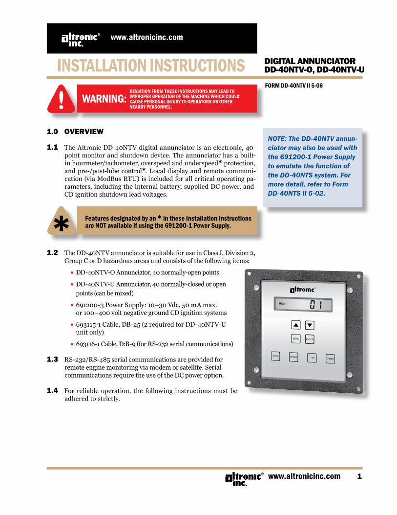
.2 TheDD-40NTVannunciatorissuitableforuseinClassI,Division2,GroupCorDhazardousareasandconsistsofthefollowingitems:
•DD-40NTV-OAnnunciator,40normally-openpoints
•DD-40NTV-UAnnunciator,40normally-closedoropen points(canbemixed)
•691200-3PowerSupply:10–30Vdc,50mAmax. or100–400voltnegativegroundCDignitionsystems
•693115-1Cable,DB-25(2requiredforDD-40NTV-U unitonly)
•693116-1Cable,D:B-9(forRS-232serialcommunications)
.3 RS-232/RS-485serialcommunicationsareprovidedforremoteenginemonitoringviamodemorsatellite.SerialcommunicationsrequiretheuseoftheDCpoweroption.
.4 For reliable operation, the following instructions must beadheredtostrictly.
DEVIATION FROM THESE INSTRUCTIONS MAY LEAD TOIMPROPER OPERATION OF THE MACHINE WHICH COULDCAUSE PERSONAL INJURY TO OPERATORS OR OTHERNEARBY PERSONNEL.
WARNING:
NOTE: The DD-40NTV annun-ciator may also be used with the 691200-1 Power Supply to emulate the function of the DD-40NTS system. For more detail, refer to Form DD-40NTS II 5-02.
Features designated by an * in these Installation Instructions are NOT available if using the 691200-1 Power Supply.

FORM DD-40NTV II 5-062
DD-40NTV DIGITAL ANNUNCIATOR
NOTE: If possible, keep the original shipping container. If future transportation or storage of the annunciator is necessary, this container will provide the optimum protection.
2.0 MOUNTING
2. ANNUNCIATOR UNIT: Usingfour#10screws,mounttheAnnunciatorUnitinsideacontrol
panel or to a suitable flat surface so that the display is at a conve-nientviewingheight.Adrillingtemplate isprovided.Theannun-ciatorunitboxmustbegrounded.
2.2 691200-3 POWER SUPPLY: ThePowerSupplymountsdirectlytothebackoftheAnnunciator
Unitusingtwo8-32x5/16"lengthscrewsprovided.
3.0 WIRING (FIGS. 7 – 20)
3. TheannunciatorunitplugsintothepowersupplythroughaDB-9connector.
3.2 Thesensorleadsconnecttotheremovableterminalstripsonthebackof theannunciator.These terminal stripsmatch thoseusedwiththeearlierDD-40NT/DD-20NTsystems.
3.3 AttheterminalstripoftheAnnunciatorunit,striptheinsulationback3/8"; twist theexposedwirestightly together.Insert theex-posed wire end completely into the terminal strip and securelytightentheclampingscrew.Itissuggestedthatwire18AWG(max.)to24AWG(min.)beusedfortheconnectionsdirectlytothean-nunciatorterminalstripconnector.
3.4 Wiresrunningtothevarioussensorsshouldbeingoodconditionorreplacedwithnewwiring.Terminationstothemainpanelter-minalstrip(ifused)shouldbemadewithasuitableterminalandcrimping toolorbysoldering.There isno requirement forexplo-sion-proofconduitorClassIenclosures;however,suitablephysicalprotectionshouldbeprovided.
NOTE: Avoid mounting with the LCD display facing direct sunlight.
The display temperature range is -40°F. to +175°F.
WARNING: REGARDING OLDER ALTRONIC OVERSPEED DEVICESIF RETROFITTING INTO AN OLDER PANEL, THE DD-40NTV ANNUNCIATOR WILL NOT RECOGNIzE THE OUTPUT SIGNAL FROM OLDER ALTRONIC OVERSPEED DEVICES: DTO-1000, DTO-1010, DTO-2200, DTO-3200 DTHO-2100, DO-3300, PTO-2100, PTHO-2100
THESE DEVICES WILL NOT WORk FOR OVERSPEED PROTECTION IN CONJUNCTION WITH A DD-40NTV ANNUNCIATOR. FOR SUCH PROTECTION, USE THE OVERSPEED FEATURE BUILT INTO THE DD-40NTV ANNUNCIATOR (REFER TO SECTION 6.3).
www.altronicinc.com 3
DD-40NTV DIGITAL ANNUNCIATOR
4.0 ANNUNCIATOR CONFIGURATION
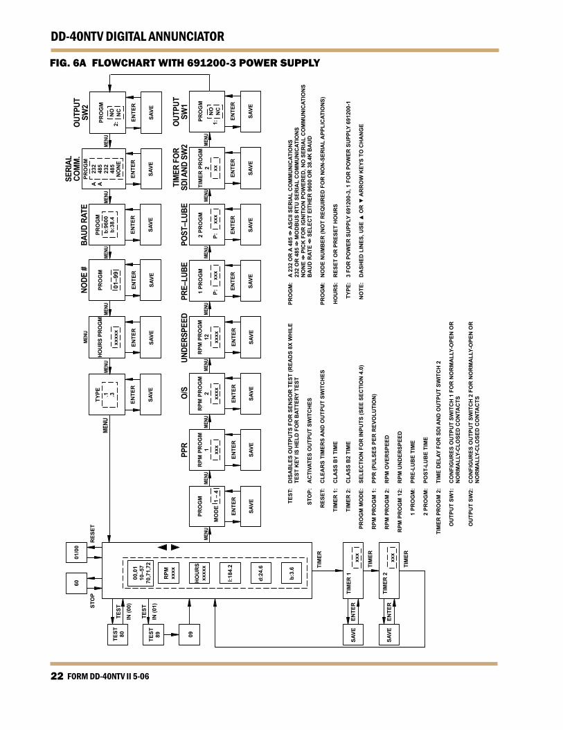
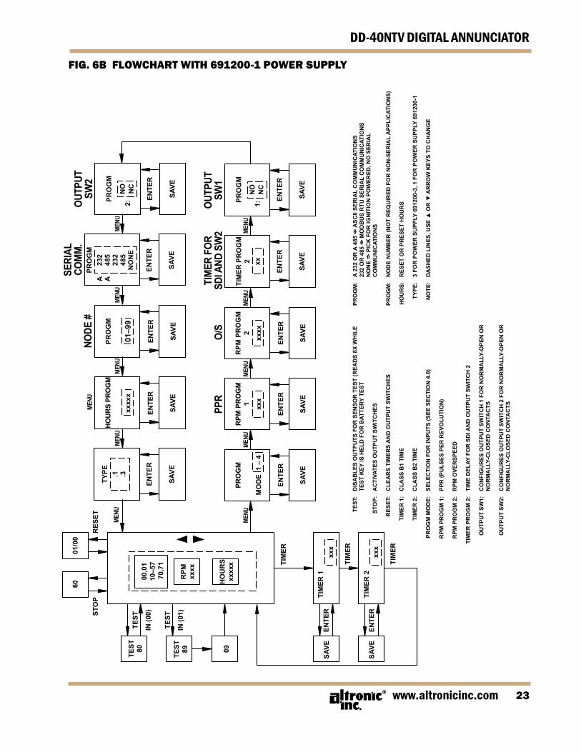
4. The DD-40NTV series unit MUST be configured prior to use. If re-placinganolderseriesDDseriesannunciator,modes1and4canbeusedtodirectlyemulatetheoldersystem’sperformance.Mode1duplicates theoperationof theDD-40seriesandmode4dupli-cates the DD-20 series units. To configure the unit, press the MENUkey to reach the configuration headings from the normal display mode.Afteraselectionhasbeenmade,presstheENTERkeytosavetheselection.PressMENUtomovetothenextstep.Af lowchart(REFER TO FIG. 6A or 6B)isprovidedthatshowsstep-by-steppro-gression through the annunciator configuration procedure.
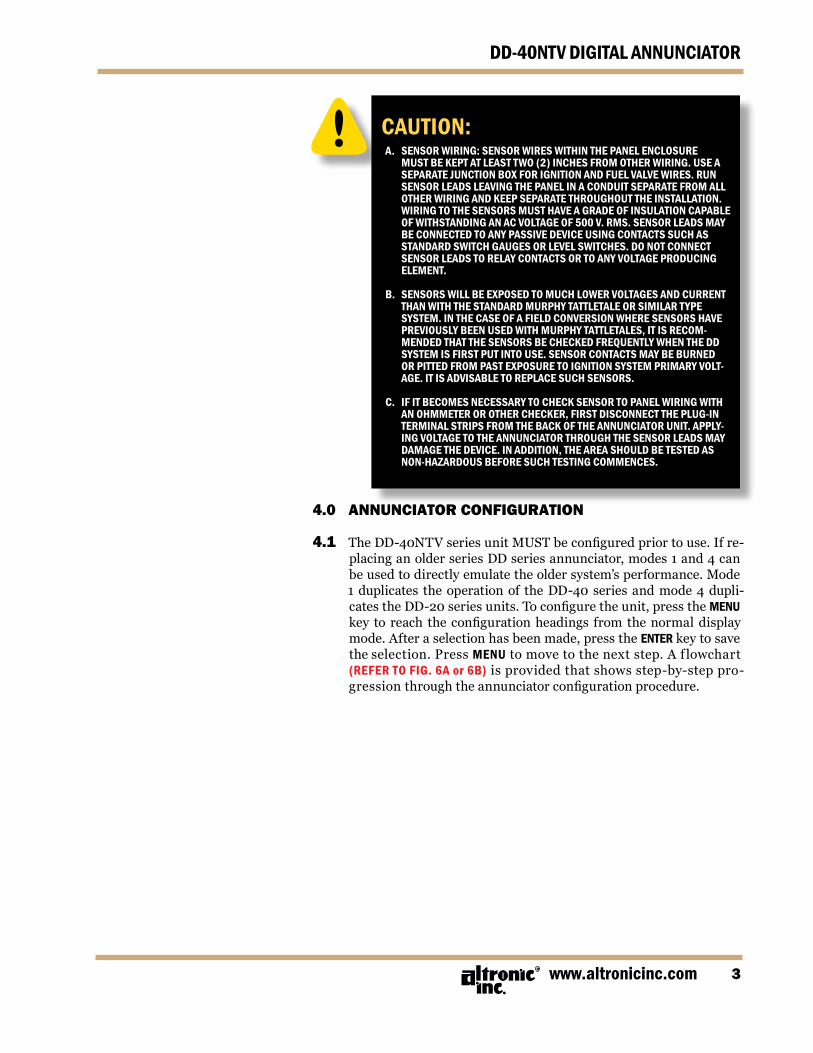
CAUTION:A. SENSOR WIRING: SENSOR WIRES WITHIN THE PANEL ENCLOSURE
MUST BE kEPT AT LEAST TWO (2) INCHES FROM OTHER WIRING. USE A SEPARATE JUNCTION BOx FOR IGNITION AND FUEL VALVE WIRES. RUN SENSOR LEADS LEAVING THE PANEL IN A CONDUIT SEPARATE FROM ALL OTHER WIRING AND kEEP SEPARATE THROUGHOUT THE INSTALLATION. WIRING TO THE SENSORS MUST HAVE A GRADE OF INSULATION CAPABLE OF WITHSTANDING AN AC VOLTAGE OF 500 V. RMS. SENSOR LEADS MAY BE CONNECTED TO ANY PASSIVE DEVICE USING CONTACTS SUCH AS STANDARD SWITCH GAUGES OR LEVEL SWITCHES. DO NOT CONNECT SENSOR LEADS TO RELAY CONTACTS OR TO ANY VOLTAGE PRODUCING ELEMENT.
B. SENSORS WILL BE ExPOSED TO MUCH LOWER VOLTAGES AND CURRENT THAN WITH THE STANDARD MURPHY TATTLETALE OR SIMILAR TYPE SYSTEM. IN THE CASE OF A FIELD CONVERSION WHERE SENSORS HAVE PREVIOUSLY BEEN USED WITH MURPHY TATTLETALES, IT IS RECOM-MENDED THAT THE SENSORS BE CHECkED FREqUENTLY WHEN THE DD SYSTEM IS FIRST PUT INTO USE. SENSOR CONTACTS MAY BE BURNED OR PITTED FROM PAST ExPOSURE TO IGNITION SYSTEM PRIMARY VOLT-AGE. IT IS ADVISABLE TO REPLACE SUCH SENSORS.
C. IF IT BECOMES NECESSARY TO CHECk SENSOR TO PANEL WIRING WITH
AN OHMMETER OR OTHER CHECkER, FIRST DISCONNECT THE PLUG-IN TERMINAL STRIPS FROM THE BACk OF THE ANNUNCIATOR UNIT. APPLY-ING VOLTAGE TO THE ANNUNCIATOR THROUGH THE SENSOR LEADS MAY DAMAGE THE DEVICE. IN ADDITION, THE AREA SHOULD BE TESTED AS NON-HAzARDOUS BEFORE SUCH TESTING COMMENCES.
FORM DD-40NTV II 5-064
DD-40NTV DIGITAL ANNUNCIATOR
4.2 CONFIGURE MODE: Themodeselectionallowstheunittobeprogrammedinoneoffour
modesasshown.TheRESETbuttonmustbepressedafterachangeinmodenumber.
MODE TYPE OF POINTS CHANNELS NOTES
1 24 Class A 30-37, 40-47, 50-57 Duplicates operation 16 Class B1 10-17, 20-27 DD-40NT series.
2 24 Class A 30-37, 40-47, 50-57 12 Class B1 10-17, 20-23 4 Class B2 24-27
3 24 Class A 30-37, 40-47, 50-57 10 Class B1 10-17, 20-21 2 Class B2 22-23 4 Class C 24-27
4 12 Class A 20-27, 30-32, 40 Duplicates operation 8 Class B1 10-17 of DD-20NT series.
Class Definitions: ClassA Pointisalwaysarmed. ClassB1 PointisarmedB1timeafterpower-uporpressingthe RESETkey. ClassB2 PointisarmedB2timeafterpower-uporpressingthe RESETkey. ClassC Pointisarmedafteritclears.
UsetheUPandDOWNkeystoselectthemodeandpresstheENTERkeytosavethemode.
4.3 PROGRAM RPM 1: This selects the RPM pre-divide number equal to the pulses per
revolution(PPR).TheRPMsignalcanbefromeitheraCDignitionshutdownleadoramagneticpickup.Therangeisselectablefrom0.5to361PPR.UsetheUPandDOWNkeystoselecttheproperpre-dividenumberandpresstheENTERkeytosave.
4.4 PROGRAM RPM 2: ThisselectstheRPMoverspeedvalue.Therangeisselectablefrom
1to2499RPM.UsetheUPandDOWNkeystoselecttheoverspeedvalueandpresstheENTERkeytosavetheselection.Todisabletheoverspeedfunction,enter2500.
NOTE: A keypad sequence (password) is required to edit values. From the sta-tus screen press and hold the ENTER key, then press the MENU key allow values to be modified. Otherwise, selected items may only be viewed. There is no similar protection for the TIMER button (Class B1 and B2 timers) or hourmeter.
www.altronicinc.com
DD-40NTV DIGITAL ANNUNCIATOR
4. PROGRAM RPM 12*: ThisselectstheRPMunderspeedvalue.Therangeisselectablefrom
0to2500RPM.UsetheUPandDOWNkeystoselecttheunderspeedvalueandpresstheENTERkeytosavetheselection.Todisabletheunderspeedfunction,enter2500.
4.6 PROGRAM PRE-LUBE P1*: ThisselectsthetimedelayinsecondsforwhichtheLUBE(LUB)out-
putisactuatedonstart-up.Therangeisfrom1to999seconds.Usethe UP and DOWN keys to select the desired pre-lube time (in sec-onds)andpresstheENTERkeytosavetheselection.Enteringavalueofzero(0)asthesetpointdisablesthepre-lubefunction.
4.7 PROGRAM POST-LUBE P2*: This selects the time delay in seconds for which the LUBE (LUB)
outputisactuatedfollowingamanualSTOPorSHUTDOWN.Therangeisfrom1to999seconds.UsetheUPandDOWNkeystoselectthedesiredpost-lubetime(inseconds)andpresstheENTERkeytosavetheselection.Enteringavalueofzero(0)asthesetpointdis-ablesthepost-lubefunction.
4.8 PROGRAM TIMER 2: ThisselectsthetimedelayinsecondsfortrippingSDIandOUTPUT
2afterafaultoccurs.Therangeofthedelayisfrom1to60seconds.UsetheUPandDOWNkeystoselectthetimeandpresstheENTERkeytosavetheselection.Intypicalapplications,SW1isusedtoturnoffthefuelandeitherSDIorSW2isusedtoturnofftheignition.
4.9 PROGRAM SW1: ThisselectstheRUNstateofoutputSW1,normallyopen(N.O.)or
normallyclosed(N.C.).UsetheUPandDOWNkeystoselectthestateandpressENTERtosave.
4.0 PROGRAM SW2: ThisselectstheRUNstateofoutputSW2,normallyopen(N.O.)or
normallyclosed(N.C.).UsetheUPandDOWNkeystoselectthestateandpressENTERtosave.
4. PROGRAM SERIAL MODE: Thisselects thetypeofcommunicationsusedbytheannunciator.
SelectionsareprovidedforNONE(mustbeusedforignitionpow-ered applications), RS-232 ASCII (A 232), RS-232 Modbus RTU(232),RS-485ASCII(A485),orRS-485ModbusRTU(485).UsetheUPandDOWNkeystoselectthestateandpressENTERtosave.
4.2 PROGRAM BAUD RATE*: Thisselectsthebaudrateforcommunications.Selecteither9600or
38.4kbaud.UsetheUPandDOWNkeystoselectthebaudrateandpresstheENTERkeytosavetheselection.Thisappliesonlyforserialcommu-nicationsandneednotbeprogrammedfornon-serialapplications.
FORM DD-40NTV II 5-066
DD-40NTV DIGITAL ANNUNCIATOR
4.3 PROGRAM NODE NUMBER: Thisselectsthenodenumberfortheannunciator.Therangeofthe
nodenumberisfrom01to99.UsetheUPandDOWNkeystoselectthenodenumberandpresstheENTERkeytosavetheselection.Thisap-pliesonlyforserialcommunicationsandneednotbeprogrammedfornon-serialapplications.
4.4 PROGRAM HOURS: This selects the pre-programmed number of hours. The range is
from00000to65535hours.PresstheUPandDOWNarrowkeystomodifythehours,thenpresstheENTERkeytosave.
4. PROGRAM TYPE: This selects the typeofPowerSupplybeingusedwith thesystem;
type.1for691200-1(NTSmode)ortype.3for691200-3(NTVmode).
4.6 TIMER kEY: ThisselectstheB1andB2timerdelays.Therangeisfrom1to999
seconds.PressingtheTIMERkeyoncedisplaystheB1timer,andpressingtheTIMERkeyagaindisplaystheB2timer.UsetheUPandDOWNkeystochangetherespectiveBtimerandpresstheENTERkeytosavetheselection.
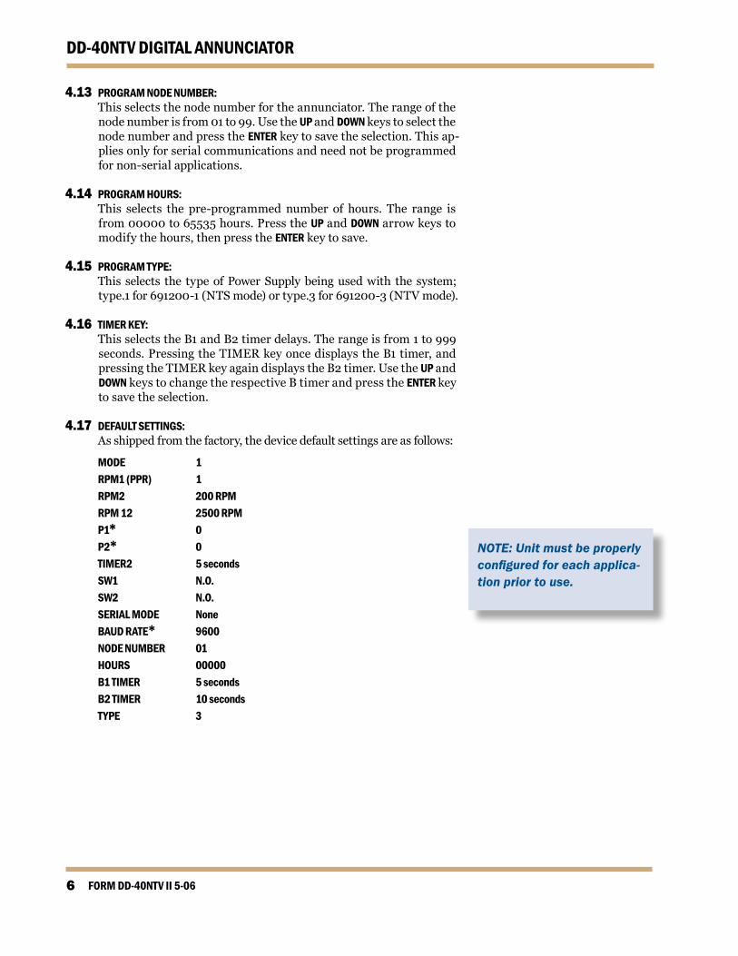
4.7 DEFAULT SETTINGS: Asshippedfromthefactory,thedevicedefaultsettingsareasfollows:
MODE 1 RPM1 (PPR) 1 RPM2 200 RPM RPM 12 2500 RPM P1* 0 P2* 0 TIMER2 5 seconds SW1 N.O. SW2 N.O. SERIAL MODE None BAUD RATE* 9600 NODE NUMBER 01 HOURS 00000 B1 TIMER 5 seconds B2 TIMER 10 seconds TYPE 3
NOTE: Unit must be properly configured for each applica-tion prior to use.
www.altronicinc.com 7
DD-40NTV DIGITAL ANNUNCIATOR
.0 KEYPAD DESCRIPTION/FUNCTION
. MENU: Thiskeyallowstheusertoview/changethefollowing:
•Modeselection •Pulsesperrevolution •Overspeedvalue •Underspeedvalue* •Pre-lubeon-time* •Post-lubeon-time* •Outputswitch1 •Outputswitch2 •Communications •Baudrate* •Outputtimer2 •Nodenumber •Programmedhours •PowerSupplyType
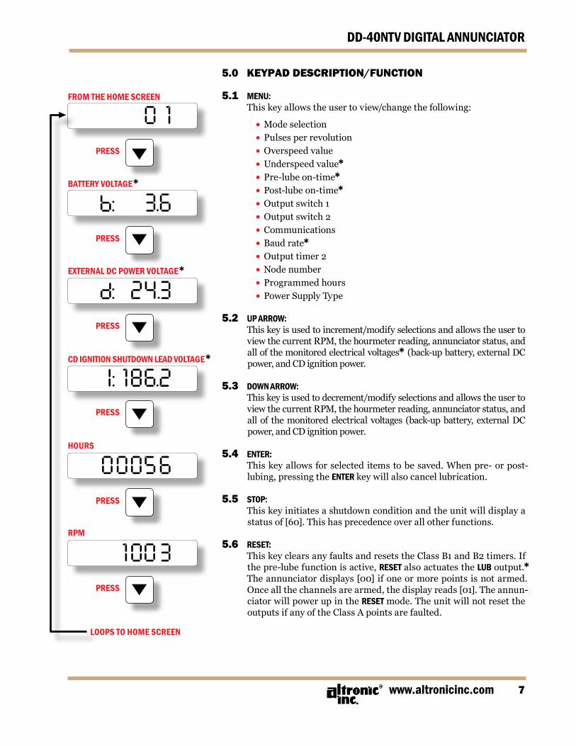
.2 UP ARROW: Thiskeyisusedtoincrement/modifyselectionsandallowstheuserto
viewthecurrentRPM,thehourmeterreading,annunciatorstatus,andallofthemonitoredelectricalvoltages*(back-upbattery,externalDCpower,andCDignitionpower.
.3 DOWN ARROW: Thiskeyisusedtodecrement/modifyselectionsandallowstheuserto
viewthecurrentRPM,thehourmeterreading,annunciatorstatus,andallof themonitoredelectricalvoltages (back-upbattery,externalDCpower,andCDignitionpower.
.4 ENTER: Thiskeyallowsforselecteditemstobesaved.Whenpre-orpost-
lubing,pressingtheENTERkeywillalsocancellubrication.
. STOP: Thiskeyinitiatesashutdownconditionandtheunitwilldisplaya
statusof[60].Thishasprecedenceoverallotherfunctions.
.6 RESET: ThiskeyclearsanyfaultsandresetstheClassB1andB2timers.If
thepre-lubefunctionisactive,RESETalsoactuatestheLUBoutput.* Theannunciatordisplays[00]ifoneormorepointsisnotarmed.Onceallthechannelsarearmed,thedisplayreads[01].Theannun-ciatorwillpowerupintheRESETmode.TheunitwillnotresettheoutputsifanyoftheClassApointsarefaulted.
LOOPS TO HOME SCREEN
FROM THE HOME SCREEN
BATTERY VOLTAGE*
ExTERNAL DC POWER VOLTAGE*
CD IGNITION SHUTDOWN LEAD VOLTAGE*
PRESS
I: 186.2
24.38:
3.66:
0 1PRESS
PRESS
PRESS
PRESS
0005 6
100 3PRESS
RPM
HOURS
FORM DD-40NTV II 5-068
DD-40NTV DIGITAL ANNUNCIATOR
.7 TEST: Thiskeyprovidesforbatteryandoperatingvoltagetestsandalso
allowsinputstobetested(faulted)withoutcausingashutdown.Thebattery inthePowerSupplymaybecheckedwhenthemachine isdownandthedisplayreads[00];pushandholdtheTESTkey–aread-ingof[80]indicatessatisfactorybatteryvoltage.Theoperatingvolt-agemaybecheckedwhenthemachineisoperatingandthedisplayreads[01];pushandholdtheTESTkey–areadingof[89]indicatestheoperatingvoltageisacceptable.Totestthesensorinputpoints,the annunciator must first be displaying [01] meaning all points are armed.PushandreleasetheTESTkey,andthedisplaywillread[09]indicatingtheTestMode.Faultedpointswillbedisplayedbutwillnotcause theoutputs to trip.Testinganadditionalpoint requirestheTESTkeytobepressedagain.Theannunciatorwillremainintestmode for twominutesbefore revertingback to the runningmode[01].Anypointnotclearedintwominutes(eitherbypressingtheTESTorRESETkey)willcausetheoutputstotrip.
.8 TIMER: This key allows the B1 and B2 delay timers to be viewed or modified.
.9 kEYPAD SEqUENCE (PASSWORD) PROTECTION: Fromthestatusscreen,pressandholdtheENTERkey,thenpressthe
MENU key to allow values to be modified. Otherwise, the selected itemsmayonlybeviewed.ThereisnokeypadsequenceprotectionfortheTIMERkey(ClassB1andB2timers).
.0 CANCEL TIMERS: Fromthestatusscreen,depresstheENTERkey.WhileholdingtheENTER
key,alsopresstheDOWN ARROW key.
6.0 OPERATION Seechartonnextpage.
NOTE: Two fault occurrences will override the TEST mode: manual STOP function [60] and OVERSPEED [70].
www.altronicinc.com 9
DD-40NTV DIGITAL ANNUNCIATOR
NOTE:
a.) TEST cannot be used until the start-up timer interval ends – [01] on the display.
b.) A display reading of [09] means the system output will not activate unless the STOP button is pushed.
c.) Do not leave a sensor number on the display after the last test; push the TEST button to get [09] on the display; then wait two minutes until [01] displays or select the CANCEL TIMERS feature.
d.) For a complete system test, allow the test timer interval to expire – display changes from [09] to [01] – then cause one sensor to fault and allow the sys-tem output to activate. This will test the entire sys-tem for correct operation upon a fault with minimal downtime.
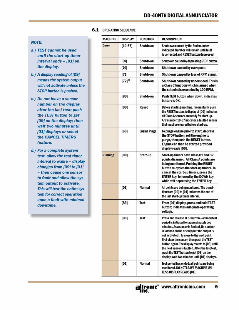
6. OPERATING SEqUENCE MACHINE DISPLAY FUNCTION DESCRIPTION Down [10-57] Shutdown Shutdown caused by the fault number
indicated. Number will remain until fault is corrected and RESET button depressed.
[60] Shutdown Shutdown caused by depressing STOP button.
[70] Shutdown Shutdown caused by overspeed.
[71] Shutdown Shutdown caused by loss of RPM signal.
[72]* Shutdown Shutdown caused by underspeed. This is a Class C function which is armed when the setpoint is exceeded by 100 RPM.
[80] Shutdown Push TEST button when down, indicates battery is Ok.
[00] Reset Before starting machine, momentarily push the RESET button. A display of [00] indicates all Class A sensors are ready for start-up. Any number 10-57 indcates a faulted sensor that must be cleared before start-up.
[60] Engine Purge To purge engine prior to start, depress the STOP button, roll the engine to purge, then push the RESET button. Engine can then be started provided display reads [00].
Running [00] Start-up Start-up timers have Class B1 and B2 points disarmed. All Class A points are being monitored. Pushing the RESET button re-cycles the start-up timers. To cancel the start-up timers, press the ENTER key, followed by the DOWN key while still depressing the ENTER key.
[01] Normal All points are being monitored. The transi- tion from [00] to [01] indicates the end of
the last start-up timer interval.
[89] Test From [01] display, press and hold TEST button; indicates adequate operating voltage.
[09] Test Press and release TEST button – a timed test period is initiated for approximately two
minutes. As a sensor is faulted, its number is latched on the display (but the output is not activated). To move to the next point, firstclearthesensor,thenpushtheTEST button again. The display reverts to [09] until the next sensor is faulted. After the last test, push the TEST button to get [09] on the display; wait two minutes until [01] displays.
[01] Normal Test period has ended; all points are being monitored. DO NOT LEAVE MACHINE UN- LESS DISPLAY READS [01].
FORM DD-40NTV II 5-060
DD-40NTV DIGITAL ANNUNCIATOR
6.2 RPM/HOURMETER: PresstheUPandDOWNkeystoviewtheRPM,hourmeterandvolt-
ages*.TheRPMscreenremainsuntiltheoperatorchoosesanotheroption.TheHOURSdisplaywillreverttothestatusscreenaftertwominutes.Ineithercase,theannunciatorwilldisplaythefaultnum-berwhenashutdownoccurs.
6.3 RPM OVERSPEED PROTECTION: TheDD-40NTVannunciatorhasabuiltintachometertomonitor
engineoverspeed.WhenthedetectedRPMisgreaterthantheRPMoverspeedsetpoint,theannunciatorwilltripthefuelandignitionoutputs.Whenthisoccurs,theunitwilldisplay[70]andactivatetheFAULTindicator.REFER TO FIGS. 7 — 20forthefurtherdetails.
6.4 RPM UNDERSPEED PROTECTION*: TheDD-40NTVannunciatorhasabuiltintachometertomonitor
engineunderspeed.Thispointisarmedwhentheunderspeedset-pointisexceededby100RPM.Oncearmed,shouldthemonitoredRPMfallbelowthesetpoint,theannunciatorwilltripthefuelandignitionoutputs.Whenthisoccurs,theunitwilldisplay[72]andactivatetheFAULTindicator.REFER TO FIGS. 7 — 20forfurtherdetails.
6. BATTERY: ThePowerSupplycontainsaspeciallong-lifelithiumbattery.When
themonitoredequipmentisnotoperating,currentdrawfromthebatteryisonlymicroamps(millionthsofamps).Whentheannun-ciatorispowered,thereisnodrainfromthebattery.Thisallowsforabatterylifeofupto5yearsinnormaloperation.Thebatteryinthepowersupply isreplaceable;useONLYAltronicpartno.601952.BesuretoobservetheproperpolarityasmarkedinthePowerSup-plywhenreplacingthebattery.
THE DD-40NTV ANNUNCIATOR WILL NOT RECOGNIzE THE OUTPUT SIGNAL FROM AN ALTRONIC DTO-3200 OR OTHER OLDER OVERSPEED DEVICES (SEE LISTING ON PAGE 2). THESE DEVICES WILL NOT WORk FOR OVERSPEED PROTEC-TION IN CONJUNCTION WITH A DD-40NTV ANNUNCIATOR.FOR SUCH PROTECTION, USE THE OVERSPEED FEATURE BUILT INTO THE DD-40NTV ANNUNCIATOR.
WARNING:
www.altronicinc.com
DD-40NTV DIGITAL ANNUNCIATOR
7.0 FAULT OUTPUTS
7. Twodigitaloutputs,SW1andSW2areinthePowerSupply.Thesearerated400voltsDC,0.5ampmaximum.
7.2 OutputSW1willtripimmediatelyuponafaultconditionorifthe
STOPkeyisdepressed.7.3 OutputsSDIandSW2willtripafterapre-programmedtimedelay
(TIMERPROGM2)fromeitherafaultconditionoriftheSTOPkeyisdepressed.
7.4 ForPowerSupplies691200-1and691200-3,themaximumvoltage
is 400 volts from a negative ground C.D. ignition with a currentdrainofmicroamps.Themaximumcurrentratingis50mAwhenpoweredfromaDCvoltagesourceof10to30volts.
FORM DD-40NTV II 5-062
DD-40NTV DIGITAL ANNUNCIATOR
8.0 PRE-LUBE/POST-LUBE OUTPUT*8. One(1)digitaloutputLUBislocatedinthepowersupply691200-3*.
Itisrated400voltsDC,0.5ampmaximum.
8.2 OutputLUBwillbeactuatedundertwooperatingconditions:
• Following a RESET (remote or manual), the LUB output will remain actuated until the pre-lube timer (P1) expires. • Following a manual STOP or FAULT, the LUB output will remain actuated until the post-lube timer (P2) expires.
9.0 SERIAL COMMUNICATIONS
9. SerialcommunicationsmaybeselectedasRS-232orRS-485usingASCIIorModbusRTUprotocol.
9.2 MASTER/SLAVE OPERATION: TheRS-485communicationsystemintheannunciatorisdesigned
as a master/slave system; that is, each unit responds to its ownuniqueaddress(nodenumber)onlyafterit is interrogatedbythemaster(computer).Asimplecommand/responseprotocolmustbestrictlyobserved.
9.3 NODE NUMBER: Thenodenumberisusedinthesystemtoidentifythedesiredslave
unitbeingpolled.Thenodenumbercanbeanynumericvaluefrom1to99.
9.4 ASCII COMMUNICATION: Allcommunicationtoandfromtheannunciatorisperformedusing
ASCIIcharacters.Thisallowstheinformationtobeprocessedwiththe “string” functions common to high level computer languagessuchasBASICandC.Forcomputersthatsupportstandardserialportinterfaces,nospecialmachinelanguagesoftwaredriversarerequired.TheuseoftheASCIIformatalsoallowsfortheconnec-tionof thesedevices toanautoanswermodemfor longdistanceoperationwithouttheneedforalocalsupervisorycomputer.TheASCIIcharactersalsomakesystemdebuggingeasyusingstandardterminalemulationsoftware.
9. COMMUNICATIONS PARAMETERS:
• Baud Rate: 9600 or 38.4k* • Data Bits: 8 • Stop Bits: 1 • Parity: None
NOTE: The letter “L” will ap-pear in the display when the LUB output has been actu-ated. To cancel the pre-lube or post-lube countdown tim-ers, press the ENTER key. If pre-lubing, the annunciator will immediately initiate the Class B timer(s).
www.altronicinc.com 3
DD-40NTV DIGITAL ANNUNCIATOR
9.6 COMMAND STRUCTURE: Theannunciatoroperateswithasimplecommand/responseprotocol
tomonitorallfunctions.Acommandmustbetransmittedtotheunitbythemaster(computerorPLC)beforetheslavecanrespondwithuse-fuldata.Aslaveunitcanneverinitiateacommunicationssequence.
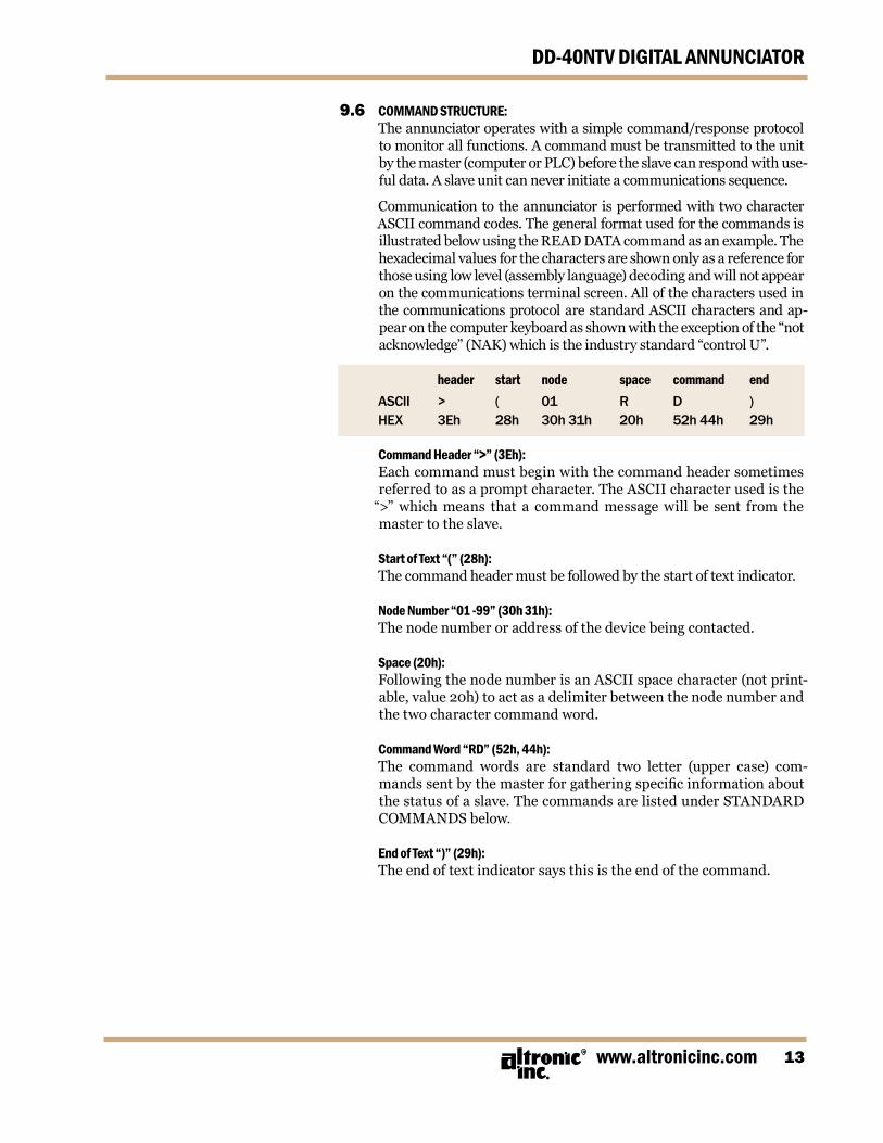
Communicationtotheannunciator isperformedwithtwocharacterASCIIcommandcodes.ThegeneralformatusedforthecommandsisillustratedbelowusingtheREADDATAcommandasanexample.Thehexadecimalvaluesforthecharactersareshownonlyasareferenceforthoseusinglowlevel(assemblylanguage)decodingandwillnotappearonthecommunicationsterminalscreen.AllofthecharactersusedinthecommunicationsprotocolarestandardASCIIcharactersandap-pearonthecomputerkeyboardasshownwiththeexceptionofthe“notacknowledge”(NAK)whichistheindustrystandard“controlU”.
header start node space command end ASCII > ( 01 R D ) HEX 3Eh 28h 30h31h 20h 52h44h 29h
Command Header “>” (3Eh): Eachcommandmustbeginwiththecommandheadersometimes
referredtoasapromptcharacter.TheASCIIcharacterusedisthe“>” which means that a command message will be sent from themastertotheslave.
Start of Text “(” (28h): Thecommandheadermustbefollowedbythestartoftextindicator. Node Number “01 -99” (30h 31h): Thenodenumberoraddressofthedevicebeingcontacted.
Space (20h): FollowingthenodenumberisanASCIIspacecharacter(notprint-
able,value20h)toactasadelimiterbetweenthenodenumberandthetwocharactercommandword.
Command Word “RD” (52h, 44h): The command words are standard two letter (upper case) com-
mands sent by the master for gathering specific information about thestatusofaslave.ThecommandsarelistedunderSTANDARDCOMMANDSbelow.
End of Text “)” (29h): Theendoftextindicatorsaysthisistheendofthecommand.
FORM DD-40NTV II 5-064
DD-40NTV DIGITAL ANNUNCIATOR
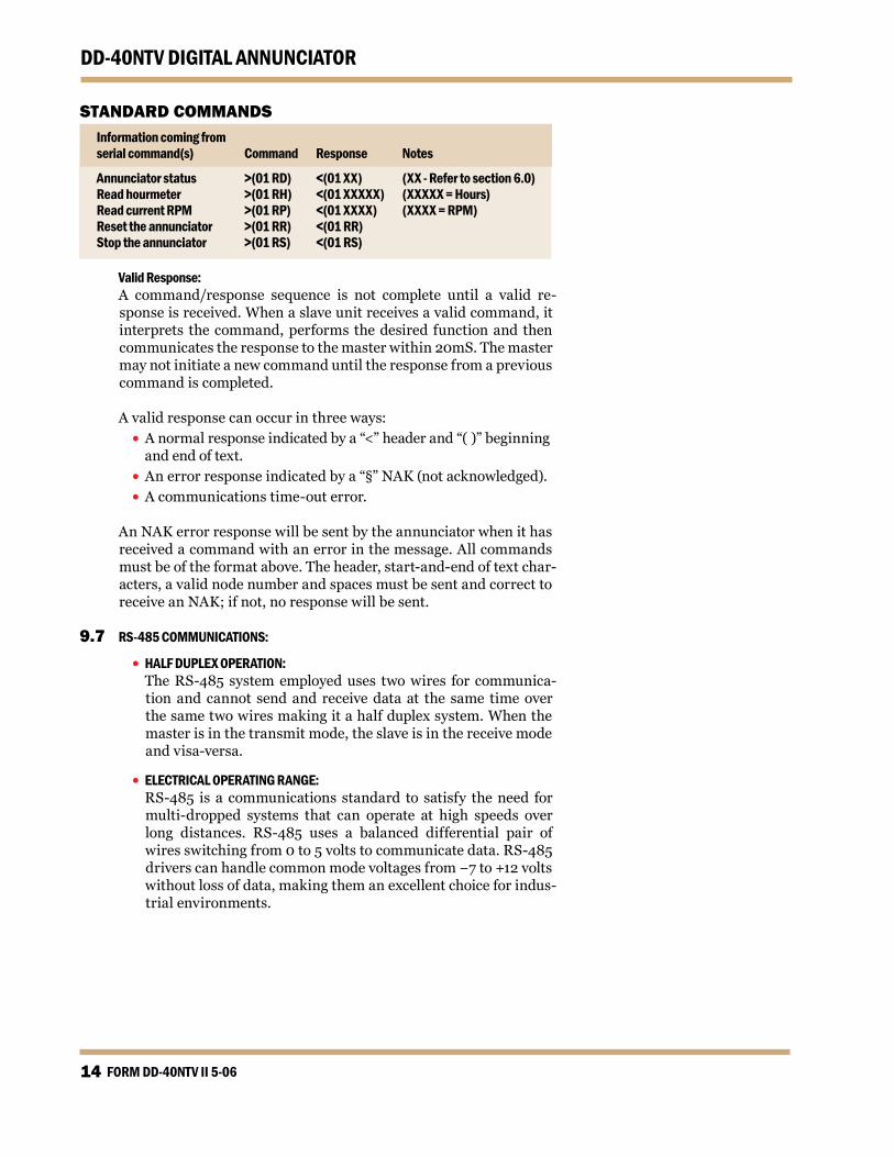
STANDARD COMMANDS Information coming from serial command(s) Command Response Notes
Annunciator status >(01 RD) <(01 xx) (xx - Refer to section 6.0) Read hourmeter >(01 RH) <(01 xxxxx) (xxxxx = Hours) Read current RPM >(01 RP) <(01 xxxx) (xxxx = RPM) Reset the annunciator >(01 RR) <(01 RR) Stop the annunciator >(01 RS) <(01 RS)
Valid Response: A command/response sequence is not complete until a valid re-
sponseisreceived.Whenaslaveunitreceivesavalidcommand,itinterprets thecommand,performsthedesired functionandthencommunicatestheresponsetothemasterwithin20mS.Themastermaynotinitiateanewcommanduntiltheresponsefromapreviouscommandiscompleted.
Avalidresponsecanoccurinthreeways: •Anormalresponseindicatedbya“<”headerand“()”beginning
andendoftext. •Anerrorresponseindicatedbya“§”NAK(notacknowledged). •Acommunicationstime-outerror.
AnNAKerrorresponsewillbesentbytheannunciatorwhenithasreceivedacommandwithanerrorinthemessage.Allcommandsmustbeoftheformatabove.Theheader,start-and-endoftextchar-acters,avalidnodenumberandspacesmustbesentandcorrecttoreceiveanNAK;ifnot,noresponsewillbesent.
9.7 RS-485 COMMUNICATIONS:
• HALF DUPLEx OPERATION: TheRS-485systememployeduses twowires forcommunica-
tion and cannot send and receive data at the same time overthesametwowiresmakingitahalfduplexsystem.Whenthemasterisinthetransmitmode,theslaveisinthereceivemodeandvisa-versa.
• ELECTRICAL OPERATING RANGE: RS-485 is a communications standard to satisfy the need for
multi-dropped systems that can operate at high speeds overlong distances. RS-485 uses a balanced differential pair ofwiresswitchingfrom0to5voltstocommunicatedata.RS-485drivers can handle common mode voltages from −7 to +12 volts withoutlossofdata,makingthemanexcellentchoiceforindus-trialenvironments.
www.altronicinc.com
DD-40NTV DIGITAL ANNUNCIATOR
• COMMUNICATIONS WIRING: TheRS-485wiringdiagramillustratesthewiringrequiredfor
multipleslaveunithookup.Notethateveryslaveunithasadi-rectconnection to themaster.Thisallowsanyoneslaveunittoberemovedfromservicewithoutaffectingtheoperationoftheotherunits.Everyunitmustbeprogrammedwithauniqueaddressornodenumber,buttheadditionofnewunitsornodescan be in any order. To minimize unwanted reflections on the transmissionline,thebusshouldbearrangedasatrunklinegoingfromonemoduletothenext.Randomstructuresofthetransmissionlineshouldbeavoided.Specialcaremustbetakenwithlongbusses(500feetormore)toensureerrorfreeopera-tion.Longbussesmustbeterminatedwitha120ohmresistorbetweentheterminalsmarkedRS-485“A”andRS-485“B”atthemasteronly.Theuseoftwistedpairshieldedcablewillen-hance signal fidelity and is recommended. To prevent ground loopstheshieldshouldbeconnectedtotheshieldterminalatthemasteronly.
• LOADING: RS-485 uses a balanced differential pair of wires switching
from 0 to 5 volts to communicate data. In situations wheremany units (99 max.) are connected together on a long run,voltage drop on the communications leads becomes a majorproblem. Voltage drops on the RS-485 minus lead appear asacommonmodevoltagetothereceivers.Whilethereceiversare rated to a maximum voltage difference of ±7 volts, −7V to +12V, a practical system should not have a voltage difference exceeding ±3 volts under normal conditions. The wire gaugeusedfortheconnectionslimitsthemaximumnumberofunitsorthemaximumlengthofwirebetweenunitsineachapplica-tion.Thefollowingformulacanbeusedasaguidelinetoselecttheappropriatewiregauge.
For 18 AWG wire No. of annunciator units = (4000)/(ft of wire used) For 20 AWG wire No. of annunciator units = (3600)/(ft of wire used) For 22 AWG wire No. of annunciator units = (2400)/(ft of wire used)
NOTE: The maximum number of units that can be connect-ed in a system is 99.
FORM DD-40NTV II 5-066
DD-40NTV DIGITAL ANNUNCIATOR
9.8 RS-232 COMMUNICATIONS: •Forproperoperation,thewirelengthshouldnotexceed50feet.
•UsestandardDB-9connectorandcomputercableAltronic 693116-xorequivalent.
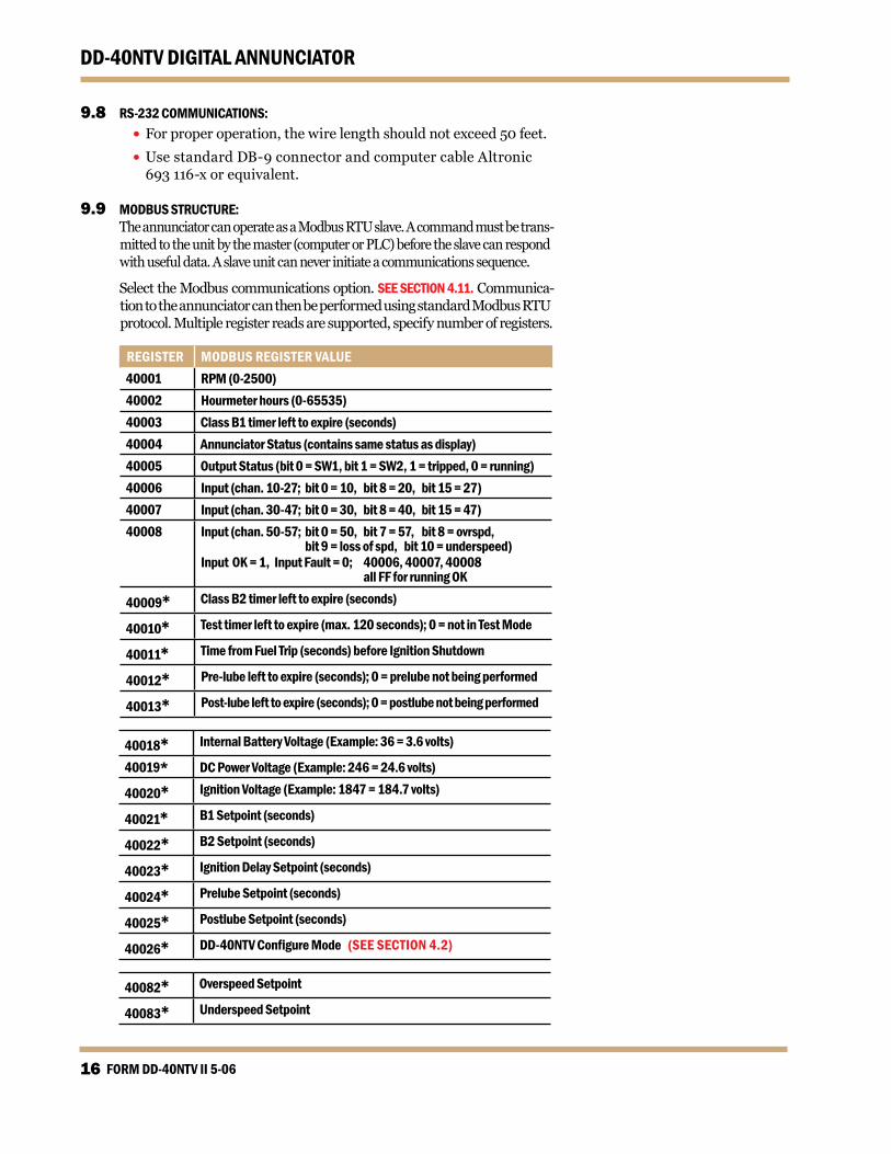
9.9 MODBUS STRUCTURE: TheannunciatorcanoperateasaModbusRTUslave.Acommandmustbetrans-
mittedtotheunitbythemaster(computerorPLC)beforetheslavecanrespondwithusefuldata.Aslaveunitcanneverinitiateacommunicationssequence.
SelecttheModbuscommunicationsoption.SEE SECTION 4.11.Communica-tiontotheannunciatorcanthenbeperformedusingstandardModbusRTUprotocol.Multipleregisterreadsaresupported,specifynumberofregisters.
REGISTER MODBUS REGISTER VALUE40001 RPM (0-2500)40002 Hourmeter hours (0-65535)40003 Class B1 timer left to expire (seconds)40004 Annunciator Status (contains same status as display)40005 Output Status (bit 0 = SW1, bit 1 = SW2, 1 = tripped, 0 = running)40006 Input (chan. 10-27; bit 0 = 10, bit 8 = 20, bit 15 = 27)40007 Input (chan. 30-47; bit 0 = 30, bit 8 = 40, bit 15 = 47)40008 Input (chan. 50-57; bit 0 = 50, bit 7 = 57, bit 8 = ovrspd,
bit 9 = loss of spd, bit 10 = underspeed)Input Ok = 1, Input Fault = 0; 40006, 40007, 40008 all FF for running Ok
40009* Class B2 timer left to expire (seconds)
40010* Test timer left to expire (max. 120 seconds); 0 = not in Test Mode
40011* Time from Fuel Trip (seconds) before Ignition Shutdown
40012* Pre-lube left to expire (seconds); 0 = prelube not being performed
40013* Post-lube left to expire (seconds); 0 = postlube not being performed
40018* Internal Battery Voltage (Example: 36 = 3.6 volts)
40019* DC Power Voltage (Example: 246 = 24.6 volts)
40020* Ignition Voltage (Example: 1847 = 184.7 volts)
40021* B1 Setpoint (seconds)
40022* B2 Setpoint (seconds)
40023* Ignition Delay Setpoint (seconds)
40024* Prelube Setpoint (seconds)
40025* Postlube Setpoint (seconds)
40026* DD-40NTVConfigureMode(SEE SECTION 4.2)
40082* Overspeed Setpoint
40083* Underspeed Setpoint
www.altronicinc.com 17
DD-40NTV DIGITAL ANNUNCIATOR
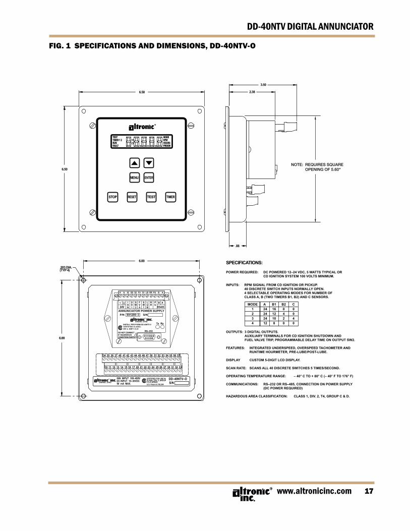
FIG. 1 SPECIFICATIONS AND DIMENSIONS, DD-40NTV-O
MENU
STOP TEST
ENTER
TIMERRESET
TESTTIMER 1 2RUNFAULT
MODERPMHOURSPROGM
6.50
3.50
2.38
.88
6.00
.203 DIA.(TYP 4)
6.00
6.50
SPECIFICATIONS:
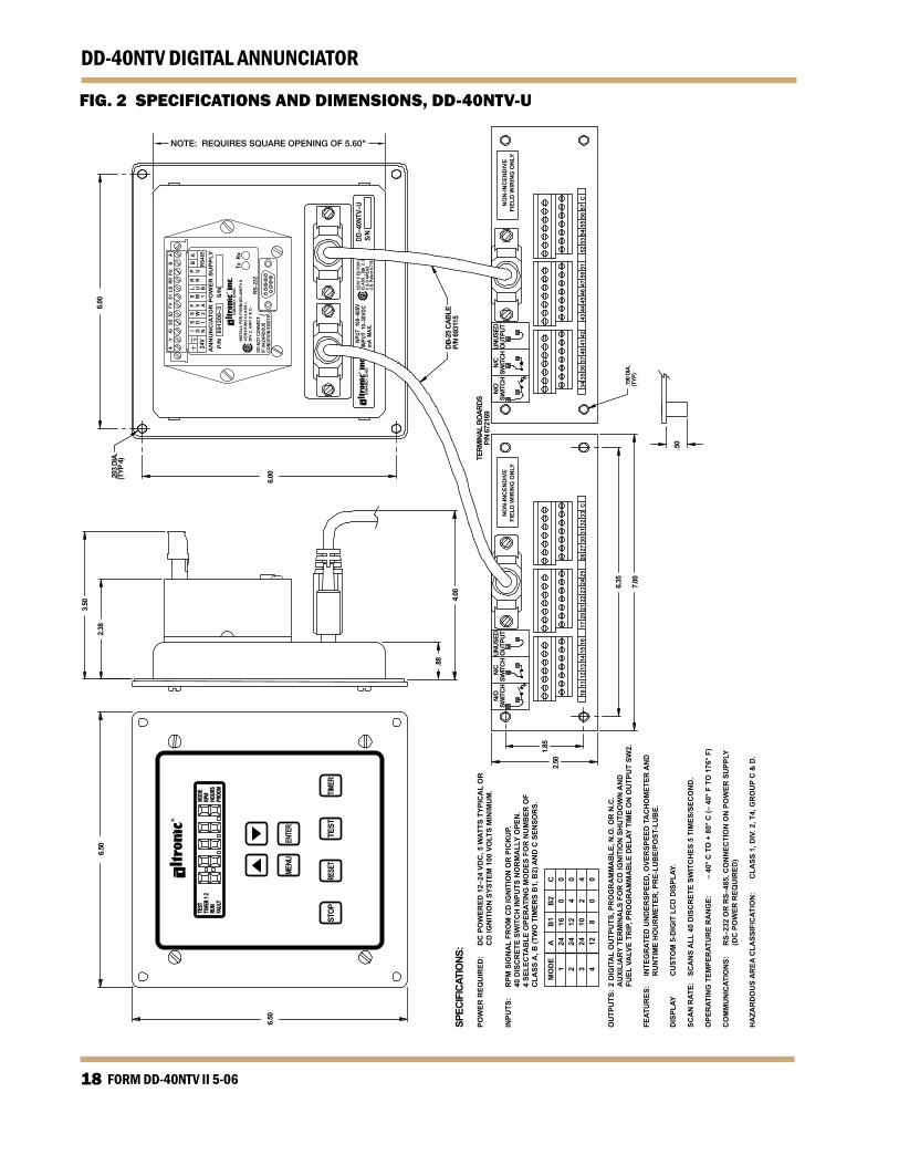
POWER REQUIRED: DC POWERED 12–24 VDC, 5 WATTS TYPICAL OR CD IGNITION SYSTEM 100 VOLTS MINIMUM.
INPUTS: RPM SIGNAL FROM CD IGNITION OR PICKUP.40 DISCRETE SWITCH INPUTS NORMALLY OPEN.4 SELECTABLE OPERATING MODES FOR NUMBER OFCLASS A, B (TWO TIMERS B1, B2) AND C SENSORS.
MODE A B1 B2 C1 24 16 0 02 24 12 4 03 24 10 2 44 12 8 0 0
OUTPUTS: 3 DIGITAL OUTPUTS.AUXILIARY TERMINALS FOR CD IGNITION SHUTDOWN ANDFUEL VALVE TRIP, PROGRAMMABLE DELAY TIME ON OUTPUT SW2.
FEATURES: INTEGRATED UNDERSPEED, OVERSPEED TACHOMETER ANDRUNTIME HOURMETER, PRE-LUBE/POST-LUBE.
DISPLAY CUSTOM 5-DIGIT LCD DISPLAY.
SCAN RATE: SCANS ALL 40 DISCRETE SWITCHES 5 TIMES/SECOND.
OPERATING TEMPERATURE RANGE: – 40° C TO + 80° C (– 40° F TO 176° F)
COMMUNICATIONS: RS–232 OR RS–485, CONNECTION ON POWER SUPPLY (DC POWER REQUIRED)
HAZARDOUS AREA CLASSIFICATION: CLASS 1, DIV. 2, T4, GROUP C & D.
RS–232DO NOT CONNECTIF HAZARDOUSCONDITION EXISTS
IGN INPUT 100–400VDC INPUT 10–30VDC50 mA MAX.
DD–40NTV–OS/N
CERTIFIED FOR USE INCLASS I, DIV. 2, GROUPC & D AREASU.S. Patent 6,738,244
Tx Rx
P/N 691200–3 S/N
GIRARD, OHIO
GIRARD, OHIO
INSTALL PER FORM DD-40NTV IICERTIFIED CLASS I,DIV 2, GRP C & D
ANNUNCIATOR POWER SUPPLY24V
IGN
B A
RS485
PU
RR
LUB
SW1
FVA
SW2
SDI
+ IG SD S2 FV S1 LB RR PU B A
NOTE: REQUIRES SQUARE OPENING OF 5.60"
FORM DD-40NTV II 5-0618
DD-40NTV DIGITAL ANNUNCIATOR3.
50
2.38
.88
4.00
1.85
2.50
6.35
7.00
.50
.190
DIA
.(T
YP)
6.00
DB-2
5 CA
BLE
P/N
6931
15
N/O
SWIT
CHN/
CSW
ITCH
UNUS
EDO
UTPU
TN/
OSW
ITCH
N/C
SWIT
CHUN
USED
OUT
PUT
TERM
INAL
BO
ARDS
P/N
6721
69
NO
N-IN
CEN
DIV
EFI
ELD
WIR
ING
ON
LYN
ON
-INC
END
IVE
FIEL
D W
IRIN
G O
NLY
34 3
5 36
37
40 4
1 42
43
44 4
5 46
47
50 5
152
53
5455
56
57C
1011
12
13 1
415
1617
2021
2223
24
25 2
6 27
3031
3233
C
.203
DIA
.(T
YP 4
)
6.00
RS–2
32DO
NOT
CON
NECT
IF H
AZAR
DOUS
COND
ITIO
N EX
ISTS
Tx R
x
P/N
69
1200
–3
S/N
GIR
AR
D, O
HIO
INST
ALL
PER
FO
RM
DD
-40N
TV II
CE
RTI
FIE
D C
LAS
S I,
DIV
2, G
RP
C &
D
AN
NU
NC
IATO
R P
OW
ER
SU
PP
LY24
VI G N
BA
RS48
5
P UR R
L U B
S W 1
F V A
S W 2
S D I
+
IG
SD S
2 F
V S
1 L
B R
R P
U B
A
DD–4
0NTV
–US/
NG
IRA
RD
, OH
IO
MENU
STOP
TEST
ENTE
R
TIMER
RESE
T
TEST
TIMER
1 2
RUN
FAUL
T
MODE
RPM
HOUR
SPR
OGM
6.50
6.50
SPEC
IFIC
ATIO
NS:
POW
ER R
EQU
IRED
: D
C P
OW
ERED
12–
24 V
DC
, 5 W
ATTS
TYP
ICA
L O
R
C
D IG
NIT
ION
SYS
TEM
100
VO
LTS
MIN
IMU
M.
INPU
TS:
RPM
SIG
NA
L FR
OM
CD
IGN
ITIO
N O
R P
ICK
UP.
40 D
ISC
RET
E SW
ITC
H IN
PUTS
NO
RM
ALL
Y O
PEN
.4
SELE
CTA
BLE
OPE
RAT
ING
MO
DES
FO
R N
UM
BER
OF
CLA
SSA
, B (T
WO
TIM
ERS
B1,
B2)
AN
D C
SEN
SOR
S.
MO
DE
A B
1B
2C
124
160
02
2412
40
324
102
44
128
00
OU
TPU
TS:
2 D
IGIT
AL
OU
TPU
TS, P
RO
GR
AM
MA
BLE
, N.O
. OR
N.C
.A
UXI
LIA
RY T
ERM
INA
LS F
OR
CD
IGN
ITIO
N S
HU
TDO
WN
AN
DFU
ELVA
LVE
TRI P
, PR
OG
RA
MM
AB
LE D
ELAY
TIM
E O
N O
UTP
UT
SW2.
FEAT
UR
ES:
INTE
GR
ATED
UN
DER
SPEE
D, O
VER
SPEE
D T
AC
HO
MET
ERA
ND
RU
NTI
ME
HO
UR
MET
ER, P
RE-
LUB
E/PO
S T- L
UB
E.
DIS
PLAY
C
US T
OM
5-D
IGIT
LC
D D
ISPL
AY.
SCA
N R
ATE:
SCA
NS
ALL
40
DIS
CR
ETE
SWIT
CH
ES 5
TIM
ES/S
ECO
ND
.
OPE
RAT
ING
TEM
PER
ATU
RE
RA
NG
E:
– 40
° C T
O +
80°
C (–
40°
F T
O 1
76° F
)
CO
MM
UN
ICAT
ION
S:R
S–23
2 O
R R
S–48
5, C
ON
NEC
TIO
N O
N P
OW
ER S
UPP
LY
(D
C P
OW
ER R
EQU
IRED
)
HA
ZAR
DO
US
AR
EA C
LASS
IFIC
ATIO
N:
CLA
SS 1
, DIV
. 2, T
4, G
RO
UP
C &
D.
U.S.
Pat
ent 6
,738
,
FIG. 2 SPECIFICATIONS AND DIMENSIONS, DD-40NTV-U
NOTE: REQUIRES SQUARE OPENING OF 5.60"
www.altronicinc.com 9
DD-40NTV DIGITAL ANNUNCIATOR
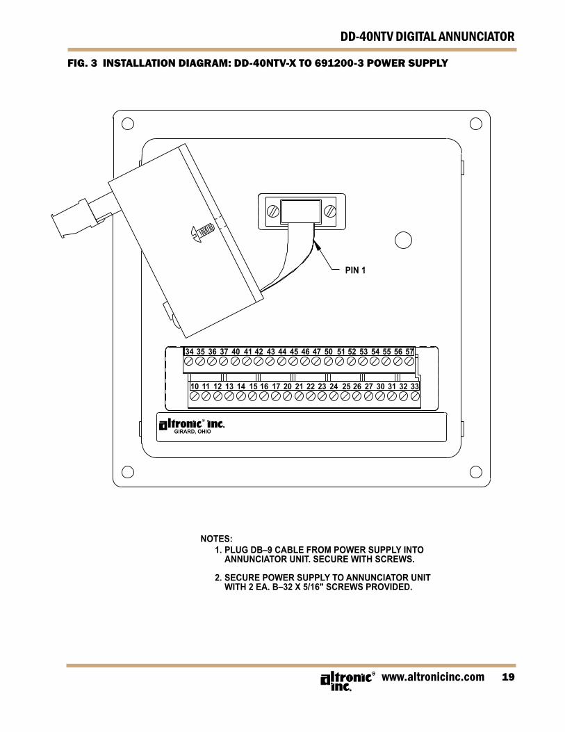
FIG. 3 INSTALLATION DIAGRAM: DD-40NTV-X TO 69200-3 POWER SUPPLY
PIN 1
GIRARD, OHIO
NOTES: 1. PLUG DB–9 CABLE FROM POWER SUPPLY INTO ANNUNCIATOR UNIT. SECURE WITH SCREWS.
2. SECURE POWER SUPPLY TO ANNUNCIATOR UNIT WITH 2 EA. B–32 X 5/16" SCREWS PROVIDED.
34 35 36 37 40 41 42 43 44 45 46 47 50 51 52 53 54 55 56 57
10 11 12 13 14 15 16 17 20 21 22 23 24 25 26 27 30 31 32 33
FORM DD-40NTV II 5-0620
DD-40NTV DIGITAL ANNUNCIATOR
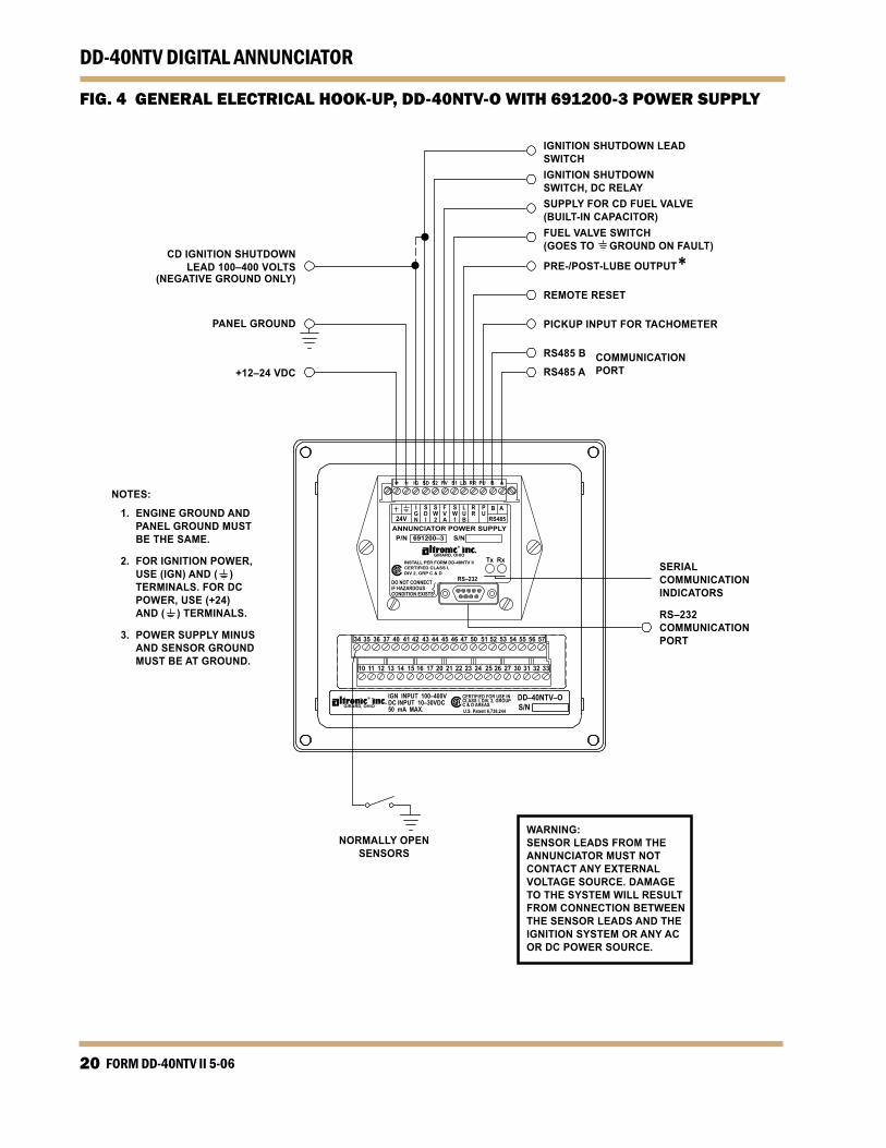
FIG. 4 GENERAL ELECTRICAL HOOK-UP, DD-40NTV-O WITH 69200-3 POWER SUPPLY
IGNITION SHUTDOWN LEADSWITCHIGNITION SHUTDOWNSWITCH, DC RELAYSUPPLY FOR CD FUEL VALVE(BUILT-IN CAPACITOR)FUEL VALVE SWITCH(GOES TO GROUND ON FAULT)
PRE-/POST-LUBE OUTPUT*REMOTE RESET
PICKUP INPUT FOR TACHOMETER
RS485 B COMMUNICATIONRS485 A PORT
CD IGNITION SHUTDOWNLEAD 100–400 VOLTS
(NEGATIVE GROUND ONLY)
PANEL GROUND
+12–24 VDC
NOTES:
1. ENGINE GROUND AND PANEL GROUND MUST BE THE SAME.
2. FOR IGNITION POWER, USE (IGN) AND ( ) TERMINALS. FOR DC POWER, USE (+24) AND ( ) TERMINALS.
3. POWER SUPPLY MINUS AND SENSOR GROUND MUST BE AT GROUND.
SERIALCOMMUNICATIONINDICATORS
RS–232COMMUNICATIONPORT
NORMALLY OPENSENSORS
WARNING:SENSOR LEADS FROM THE ANNUNCIATOR MUST NOT CONTACT ANY EXTERNAL VOLTAGE SOURCE. DAMAGE TO THE SYSTEM WILL RESULT FROM CONNECTION BETWEEN THE SENSOR LEADS AND THE IGNITION SYSTEM OR ANY AC OR DC POWER SOURCE.
www.altronicinc.com 2
DD-40NTV DIGITAL ANNUNCIATOR
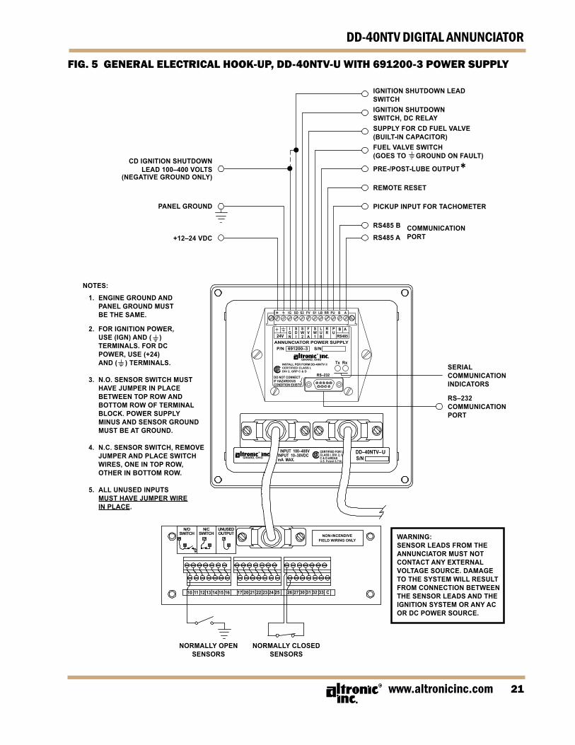
FIG. GENERAL ELECTRICAL HOOK-UP, DD-40NTV-U WITH 69200-3 POWER SUPPLY
IGNITION SHUTDOWN LEADSWITCHIGNITION SHUTDOWNSWITCH, DC RELAYSUPPLY FOR CD FUEL VALVE(BUILT-IN CAPACITOR)FUEL VALVE SWITCH(GOES TO GROUND ON FAULT)
PRE-/POST-LUBE OUTPUT*REMOTE RESET
PICKUP INPUT FOR TACHOMETER
RS485 B COMMUNICATIONRS485 A PORT
CD IGNITION SHUTDOWNLEAD 100–400 VOLTS
(NEGATIVE GROUND ONLY)
PANEL GROUND
+12–24 VDC
NOTES:
1. ENGINE GROUND AND PANEL GROUND MUST BE THE SAME.
2. FOR IGNITION POWER, USE (IGN) AND ( ) TERMINALS. FOR DC POWER, USE (+24) AND ( ) TERMINALS.
3. N.O. SENSOR SWITCH MUST HAVE JUMPER IN PLACE BETWEEN TOP ROW AND BOTTOM ROW OF TERMINAL BLOCK. POWER SUPPLY MINUS AND SENSOR GROUND MUST BE AT GROUND.
4. N.C. SENSOR SWITCH, REMOVE JUMPER AND PLACE SWITCH WIRES, ONE IN TOP ROW, OTHER IN BOTTOM ROW.
5. ALL UNUSED INPUTS MUST HAVE JUMPER WIRE IN PLACE.
SERIALCOMMUNICATIONINDICATORS
RS–232COMMUNICATIONPORT
WARNING:SENSOR LEADS FROM THE ANNUNCIATOR MUST NOT CONTACT ANY EXTERNAL VOLTAGE SOURCE. DAMAGE TO THE SYSTEM WILL RESULT FROM CONNECTION BETWEEN THE SENSOR LEADS AND THE IGNITION SYSTEM OR ANY AC OR DC POWER SOURCE.
NORMALLY OPENSENSORS
NORMALLY CLOSEDSENSORS
N/OSWITCH
N/CSWITCH
UNUSEDOUTPUT NON-INCENDIVE
FIELD WIRING ONLY
10 11 12 13 14 15 16 17 20 21 22 23 24 25 26 27 30 31 32 33 C
UU.S. Patent 6,738,
FORM DD-40NTV II 5-0622
DD-40NTV DIGITAL ANNUNCIATOR
TE
ST:
DIS
AB
LES
OU
TPU
TS F
OR
SEN
SOR
TES
T (R
EAD
S 8X
WH
ILE
TE
ST K
EY IS
HEL
D F
OR
BAT
TERY
TES
T
ST
OP:
A
CTI
VATE
S O
UTP
UT
SWIT
CH
ES
R
ESET
: C
LEA
RS
TIM
ERS
AN
D O
UTP
UT
SWIT
CH
ES
TI
MER
1:
CLA
SS B
1 TI
ME
TI
MER
2:
CLA
SS B
2 TI
ME
PR
OG
M M
OD
E:
SELE
CTI
ON
FO
R IN
PUTS
(SEE
SEC
TIO
N 4
.0)
R
PM P
RO
GM
1:
PPR
(PU
LSES
PER
REV
OLU
TIO
N)
R
PM P
RO
GM
2:
RPM
OVE
RSP
EED
RPM
PR
OG
M 1
2:
RPM
UN
DER
SPEE
D
1
PRO
GM
: PR
E-LU
BE
TIM
E
2
PRO
GM
: PO
ST-L
UB
E TI
ME
TIM
ER P
RO
GM
2:
TIM
E D
ELAY
FO
R S
DI A
ND
OU
TPU
T SW
ITC
H 2
O
UTP
UT
SW1:
C
ON
FIG
UR
ES O
UTP
UT
SWIT
CH
1 F
OR
NO
RM
ALL
Y-O
PEN
OR
NO
RM
ALL
Y-C
LOSE
D C
ON
TAC
TS
O
UTP
UT
SW2:
C
ON
FIG
UR
ES O
UTP
UT
SWIT
CH
2 F
OR
NO
RM
ALL
Y-O
PEN
OR
NO
RM
ALL
Y-C
LOSE
D C
ON
TAC
TS
PR
OG
M:
A 23
2 O
R A
485
=> A
SCII
SER
IAL
CO
MM
UN
ICAT
ION
S
23
2 O
R 4
85 =>
MO
DB
US
RTU
SER
IAL
CO
MM
UN
ICAT
ION
S
N
ON
E =>
PIC
K F
OR
IGN
ITIO
N P
OW
ERED
, NO
SER
IAL
CO
MM
UN
ICAT
ION
S
B
AU
D R
ATE
<= S
ELEC
T EI
THER
960
0 O
R 3
8.4K
BA
UD
PR
OG
M:
NO
DE
NU
MB
ER (N
OT
REQ
UIR
ED F
OR
NO
N-S
ERIA
L A
PPLI
CAT
ION
S)
H
OU
RS:
R
ESET
OR
PR
ESET
HO
UR
S
TY
PE:
3 FO
R P
OW
ER S
UPP
LY 6
9120
0-3,
1 F
OR
PO
WER
SU
PPLY
691
200-
1
N
OTE
: D
ASH
ED L
INES
, USE
O
R
AR
RO
W K
EYS
TO C
HA
NG
E
FIG. 6A FLOWCHART WITH 69200-3 POWER SUPPLY
www.altronicinc.com 23
DD-40NTV DIGITAL ANNUNCIATOR
TE
ST:
DIS
AB
LES
OU
TPU
TS F
OR
SEN
SOR
TES
T (R
EAD
S 8X
WH
ILE
TE
ST K
EY IS
HEL
D F
OR
BAT
TERY
TES
T
ST
OP:
A
CTI
VATE
S O
UTP
UT
SWIT
CH
ES
R
ESET
: C
LEA
RS
TIM
ERS
AN
D O
UTP
UT
SWIT
CH
ES
TI
MER
1:
CLA
SS B
1 TI
ME
TI
MER
2:
CLA
SS B
2 TI
ME
PR
OG
M M
OD
E:
SELE
CTI
ON
FO
R IN
PUTS
(SEE
SEC
TIO
N 4
.0)
R
PM P
RO
GM
1:
PPR
(PU
LSES
PER
REV
OLU
TIO
N)
R
PM P
RO
GM
2:
RPM
OVE
RSP
EED
TIM
ER P
RO
GM
2:
TIM
E D
ELAY
FO
R S
DI A
ND
OU
TPU
T SW
ITC
H 2
O
UTP
UT
SW1:
C
ON
FIG
UR
ES O
UTP
UT
SWIT
CH
1 F
OR
NO
RM
ALL
Y-O
PEN
OR
NO
RM
ALL
Y-C
LOSE
D C
ON
TAC
TS
O
UTP
UT
SW2:
C
ON
FIG
UR
ES O
UTP
UT
SWIT
CH
2 F
OR
NO
RM
ALL
Y-O
PEN
OR
NO
RM
ALL
Y-C
LOSE
D C
ON
TAC
TS
PR
OG
M:
A 23
2 O
R A
485
=> A
SCII
SER
IAL
CO
MM
UN
ICAT
ION
S
23
2 O
R 4
85 =>
MO
DB
US
RTU
SER
IAL
CO
MM
UN
ICAT
ION
S
N
ON
E =>
PIC
K F
OR
IGN
ITIO
N P
OW
ERED
, NO
SER
IAL
CO
MM
UN
ICAT
ION
S
PR
OG
M:
NO
DE
NU
MB
ER (N
OT
REQ
UIR
ED F
OR
NO
N-S
ERIA
L A
PPLI
CAT
ION
S)
H
OU
RS:
R
ESET
OR
PR
ESET
HO
UR
S
TY
PE:
3 FO
R P
OW
ER S
UPP
LY 6
9120
0-3,
1 F
OR
PO
WER
SU
PPLY
691
200-
1
N
OTE
: D
ASH
ED L
INES
, USE
O
R
AR
RO
W K
EYS
T O C
HA
NG
E
FIG. 6B FLOWCHART WITH 69200- POWER SUPPLY
FORM DD-40NTV II 5-0624
DD-40NTV DIGITAL ANNUNCIATOR
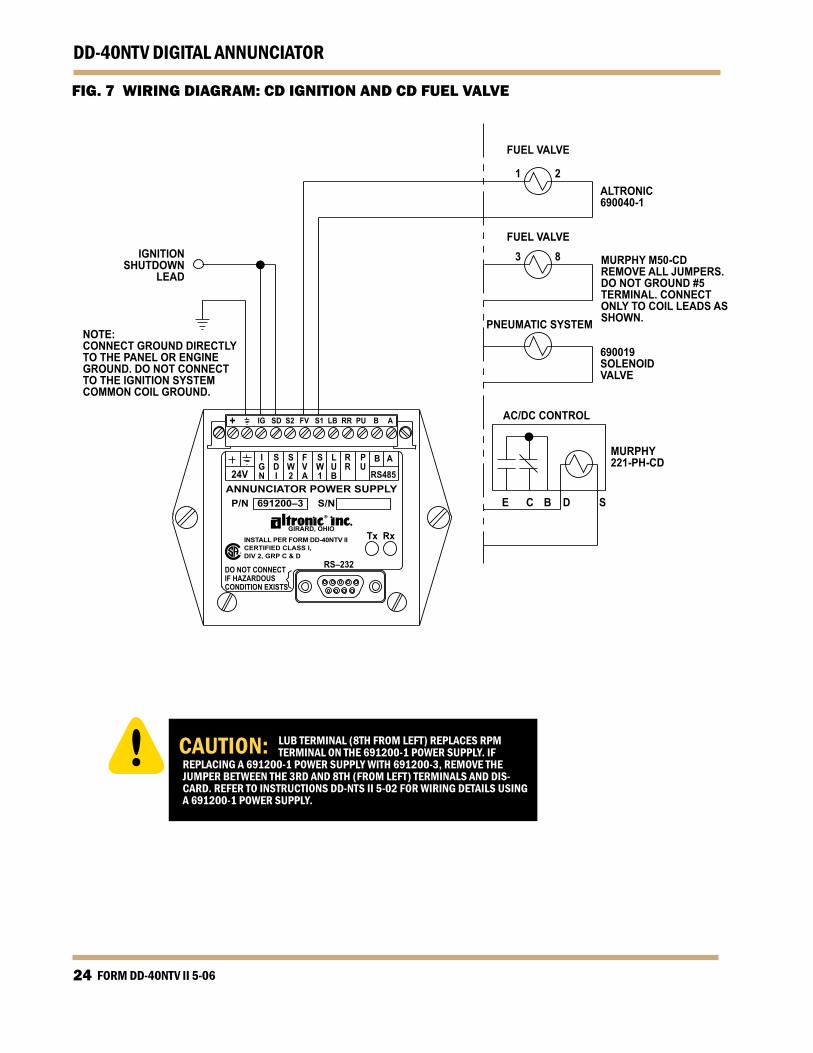
FIG. 7 WIRING DIAGRAM: CD IGNITION AND CD FUEL VALVE
RS–232DO NOT CONNECTIF HAZARDOUSCONDITION EXISTS
Tx Rx
P/N 691200–3 S/N
GIRARD, OHIOINSTALL PER FORM DD-40NTV IICERTIFIED CLASS I,DIV 2, GRP C & D
ANNUNCIATOR POWER SUPPLY24V
IGN
B A
RS485
PU
RR
LUB
SW1
FVA
SW2
SDI
+ IG SD S2 FV S1 LB RR PU B A
NOTE:CONNECT GROUND DIRECTLYTO THE PANEL OR ENGINEGROUND. DO NOT CONNECTTO THE IGNITION SYSTEMCOMMON COIL GROUND.
3 8 MURPHY M50-CDREMOVE ALL JUMPERS. DO NOT GROUND #5 TERMINAL. CONNECTONLY TO COIL LEADS AS SHOWN.PNEUMATIC SYSTEM
690019SOLENOIDVALVE
ALTRONIC690040-1
AC/DC CONTROL
FUEL VALVE
FUEL VALVE
E C B D S
MURPHY221-PH-CD
IGNITIONSHUTDOWN
LEAD
1 2
CAUTION: LUB TERMINAL (8TH FROM LEFT) REPLACES RPM TERMINAL ON THE 691200-1 POWER SUPPLY. IF REPLACING A 691200-1 POWER SUPPLY WITH 691200-3, REMOVE THE JUMPER BETWEEN THE 3RD AND 8TH (FROM LEFT) TERMINALS AND DIS-CARD. REFER TO INSTRUCTIONS DD-NTS II 5-02 FOR WIRING DETAILS USING A 691200-1 POWER SUPPLY.
www.altronicinc.com 2
DD-40NTV DIGITAL ANNUNCIATOR
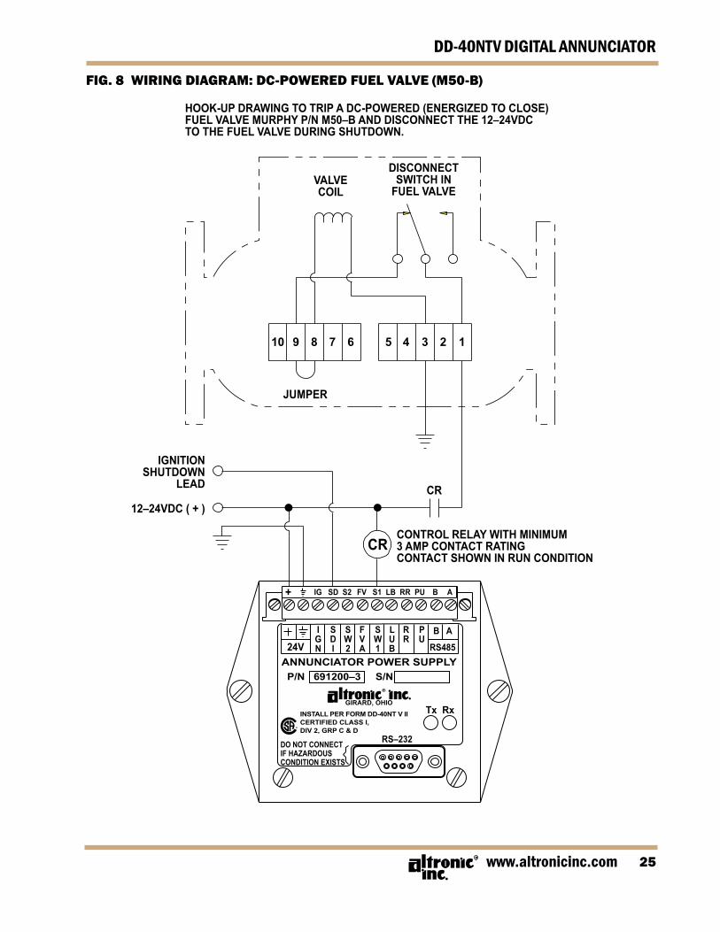
FIG. 8 WIRING DIAGRAM: DC-POWERED FUEL VALVE (M0-B)
RS–232DO NOT CONNECTIF HAZARDOUSCONDITION EXISTS
Tx Rx
P/N 691200–3 S/N
GIRARD, OHIOINSTALL PER FORM DD-40NT V IICERTIFIED CLASS I,DIV 2, GRP C & D
ANNUNCIATOR POWER SUPPLY24V
IGN
B A
RS485
PU
RR
LUB
SW1
FVA
SW2
SDI
+ IG SD S2 FV S1 LB RR PU B A
IGNITIONSHUTDOWN
LEAD
12–24VDC ( + )
VALVECOIL
JUMPER
CR
CR
DISCONNECTSWITCH IN
FUEL VALVE
CONTROL RELAY WITH MINIMUM3 AMP CONTACT RATINGCONTACT SHOWN IN RUN CONDITION
10 9 8 7 6 5 4 3 2 1
HOOK-UP DRAWING TO TRIP A DC-POWERED (ENERGIZED TO CLOSE)FUEL VALVE MURPHY P/N M50–B AND DISCONNECT THE 12–24VDCTO THE FUEL VALVE DURING SHUTDOWN.
FORM DD-40NTV II 5-0626
DD-40NTV DIGITAL ANNUNCIATOR
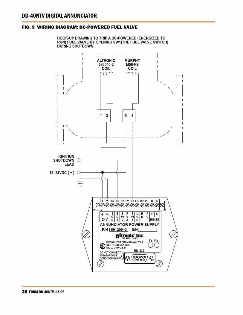
FIG. 9 WIRING DIAGRAM: DC-POWERED FUEL VALVE
MURPHYM50-FS
COIL
ALTRONIC690040-2
COIL
1 2 5 4
RS–232DO NOT CONNECTIF HAZARDOUSCONDITION EXISTS
Tx Rx
P/N 691200–3 S/N
GIRARD, OHIOINSTALL PER FORM DD-40NT V IICERTIFIED CLASS I,DIV 2, GRP C & D
ANNUNCIATOR POWER SUPPLY24V
IGN
B A
RS485
PU
RR
LUB
SW1
FVA
SW2
SDI
+ IG SD S2 FV S1 LB RR PU B A
IGNITIONSHUTDOWN
LEAD
12–24VDC ( + )
HOOK-UP DRAWING TO TRIP A DC-POWERED (ENERGIZED TO RUN) FUEL VALVE BY OPENING SW1(THE FUEL VALVE SWITCH) DURING SHUTDOWN.
www.altronicinc.com 27
DD-40NTV DIGITAL ANNUNCIATOR
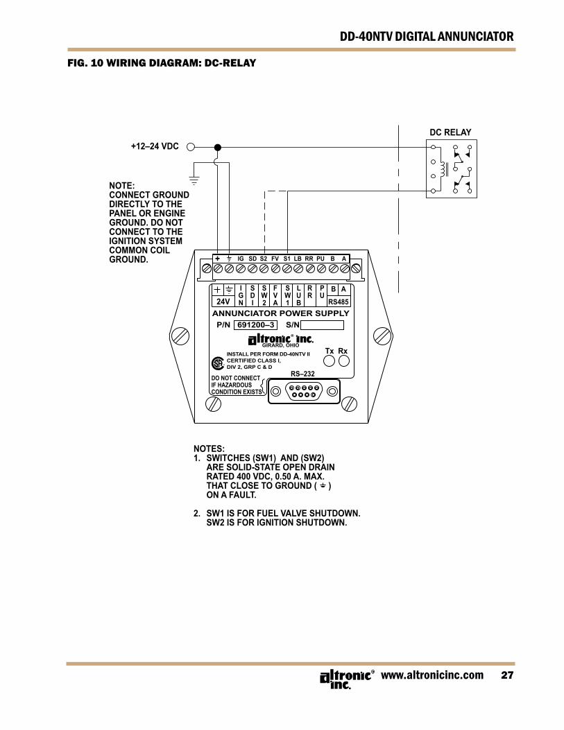
FIG. 0 WIRING DIAGRAM: DC-RELAY
NOTES:1. SWITCHES (SW1) AND (SW2) ARE SOLID-STATE OPEN DRAIN RATED 400 VDC, 0.50 A. MAX. THAT CLOSE TO GROUND ( ) ON A FAULT.
2. SW1 IS FOR FUEL VALVE SHUTDOWN. SW2 IS FOR IGNITION SHUTDOWN.
RS–232DO NOT CONNECTIF HAZARDOUSCONDITION EXISTS
Tx Rx
P/N 691200–3 S/N
GIRARD, OHIOINSTALL PER FORM DD-40NTV IICERTIFIED CLASS I,DIV 2, GRP C & D
ANNUNCIATOR POWER SUPPLY24V
IGN
B A
RS485
PU
RR
LUB
SW1
FVA
SW2
SDI
+ IG SD S2 FV S1 LB RR PU B A
+12–24 VDC
NOTE:CONNECT GROUNDDIRECTLY TO THEPANEL OR ENGINEGROUND. DO NOTCONNECT TO THEIGNITION SYSTEMCOMMON COILGROUND.
DC RELAY
FORM DD-40NTV II 5-0628
DD-40NTV DIGITAL ANNUNCIATOR
RS–232DO NOT CONNECTIF HAZARDOUSCONDITION EXISTS
Tx Rx
P/N 691200–3 S/N
GIRARD, OHIOINSTALL PER FORM DD-40NTV IICERTIFIED CLASS I,DIV 2, GRP C & D
ANNUNCIATOR POWER SUPPLY24V
IGN
B A
RS485
PU
RR
LUB
SW1
FVA
SW2
SDI
+ IG SD S2 FV S1 LB RR PU B A
RS–232DO NOT CONNECTIF HAZARDOUSCONDITION EXISTS
Tx Rx
P/N 691200–3 S/N
GIRARD, OHIO
INSTALL PER FORM DD-40NTV IICERTIFIED CLASS I,DIV 2, GRP C & D
ANNUNCIATOR POWER SUPPLY24V
IGN
B A
RS485
PU
RR
LUB
SW1
FVA
SW2
SDI
+ IG SD S2 FV S1 LB RR PU B A
+12–24 VDC
IGNITIONSHUTDOWNLEAD
PANELGROUND
+12–24 VDCDC RELAY
LUBEMOTOR
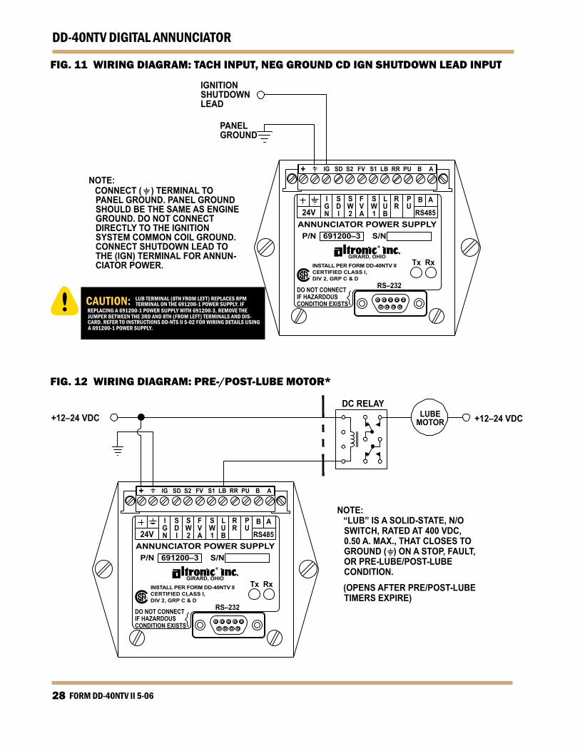
NOTE: “LUB” IS A SOLID-STATE, N/O
SWITCH, RATED AT 400 VDC, 0.50 A. MAX., THAT CLOSES TO GROUND ( ) ON A STOP, FAULT, OR PRE-LUBE/POST-LUBE CONDITION.
(OPENS AFTER PRE/POST-LUBE TIMERS EXPIRE)
NOTE: CONNECT ( ) TERMINAL TO
PANEL GROUND. PANEL GROUND SHOULD BE THE SAME AS ENGINE GROUND. DO NOT CONNECT DIRECTLY TO THE IGNITION SYSTEM COMMON COIL GROUND. CONNECT SHUTDOWN LEAD TO THE (IGN) TERMINAL FOR ANNUN-CIATOR POWER.
FIG. WIRING DIAGRAM: TACH INPUT, NEG GROUND CD IGN SHUTDOWN LEAD INPUT
FIG. 2 WIRING DIAGRAM: PRE-/POST-LUBE MOTOR*
www.altronicinc.com 29
DD-40NTV DIGITAL ANNUNCIATOR
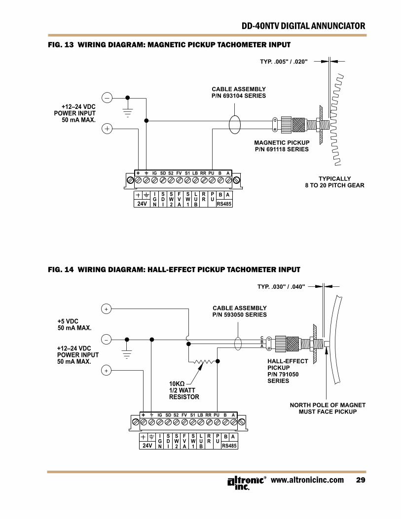
+12–24 VDCPOWER INPUT
50 mA MAX.
CABLE ASSEMBLYP/N 693104 SERIES
MAGNETIC PICKUPP/N 691118 SERIES
TYPICALLY8 TO 20 PITCH GEAR
TYP. .005" / .020"
+12–24 VDCPOWER INPUT50 mA MAX.
10KΩ1/2 WATTRESISTOR
+5 VDC50 mA MAX.
CABLE ASSEMBLYP/N 593050 SERIES
HALL-EFFECTPICKUPP/N 791050SERIES
CBA
NORTH POLE OF MAGNETMUST FACE PICKUP
TYP. .030" / .040"
24VIGN
B A
RS485
PU
RR
LUB
SW1
FVA
SW2
SDI
+ IG SD S2 FV S1 LB RR PU B A
24VIGN
B A
RS485
PU
RR
LUB
SW1
FVA
SW2
SDI
+ IG SD S2 FV S1 LB RR PU B A
FIG. 3 WIRING DIAGRAM: MAGNETIC PICKUP TACHOMETER INPUT
FIG. 4 WIRING DIAGRAM: HALL-EFFECT PICKUP TACHOMETER INPUT
FORM DD-40NTV II 5-0630
DD-40NTV DIGITAL ANNUNCIATOR
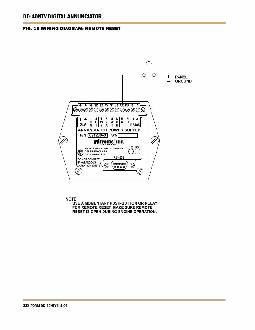
FIG. WIRING DIAGRAM: REMOTE RESET
RS–232DO NOT CONNECTIF HAZARDOUSCONDITION EXISTS
Tx Rx
P/N 691200–3 S/N
GIRARD, OHIO
INSTALL PER FORM DD-40NTV IICERTIFIED CLASS I,DIV 2, GRP C & D
ANNUNCIATOR POWER SUPPLY24V
IGN
B A
RS485
PU
RR
LUB
SW1
FVA
SW2
SDI
+ IG SD S2 FV S1 LB RR PU B A
PANELGROUND
NOTE: USE A MOMENTARY PUSH-BUTTON OR RELAY FOR REMOTE RESET. MAKE SURE REMOTE RESET IS OPEN DURING ENGINE OPERATION.
www.altronicinc.com 3
DD-40NTV DIGITAL ANNUNCIATOR
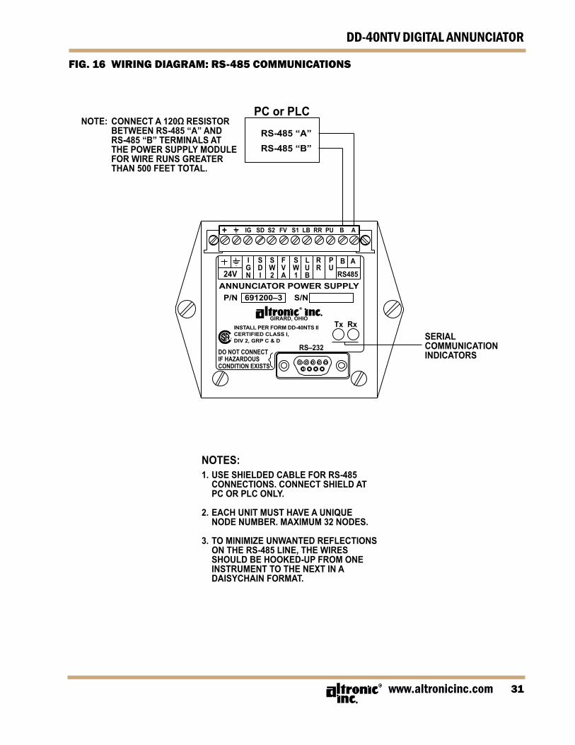
FIG. 6 WIRING DIAGRAM: RS-48 COMMUNICATIONS
NOTE: CONNECT A 120Ω RESISTOR BETWEEN RS-485 “A” AND RS-485 “B” TERMINALS AT THE POWER SUPPLY MODULE FOR WIRE RUNS GREATER THAN 500 FEET TOTAL.
SERIALCOMMUNICATIONINDICATORS
RS–232DO NOT CONNECTIF HAZARDOUSCONDITION EXISTS
Tx Rx
P/N 691200–3 S/N
GIRARD, OHIO
INSTALL PER FORM DD-40NTS IICERTIFIED CLASS I,DIV 2, GRP C & D
ANNUNCIATOR POWER SUPPLY24V
IGN
B A
RS485
PU
RR
LUB
SW1
FVA
SW2
SDI
+ IG SD S2 FV S1 LB RR PU B A
PC or PLCRS-485 “A”RS-485 “B”
NOTES:1. USE SHIELDED CABLE FOR RS-485 CONNECTIONS. CONNECT SHIELD AT PC OR PLC ONLY.
2. EACH UNIT MUST HAVE A UNIQUE NODE NUMBER. MAXIMUM 32 NODES.
3. TO MINIMIZE UNWANTED REFLECTIONS ON THE RS-485 LINE, THE WIRES SHOULD BE HOOKED-UP FROM ONE INSTRUMENT TO THE NEXT IN A DAISYCHAIN FORMAT.
FORM DD-40NTV II 5-0632
DD-40NTV DIGITAL ANNUNCIATOR
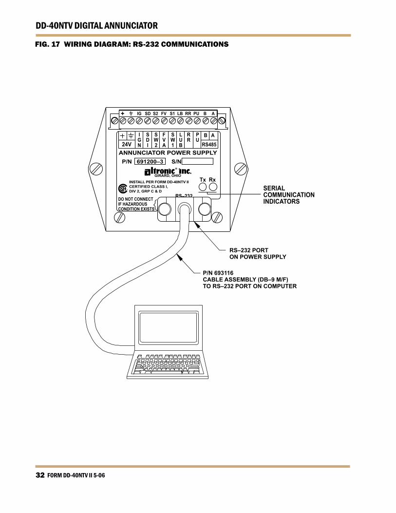
FIG. 7 WIRING DIAGRAM: RS-232 COMMUNICATIONS
SERIALCOMMUNICATIONINDICATORS
RS–232 PORTON POWER SUPPLY
P/N 693116CABLE ASSEMBLY (DB–9 M/F)TO RS–232 PORT ON COMPUTER
DO NOT CONNECTIF HAZARDOUSCONDITION EXISTS
Tx Rx
P/N 691200–3 S/N
GIRARD, OHIOINSTALL PER FORM DD-40NTV IICERTIFIED CLASS I,DIV 2, GRP C & D
ANNUNCIATOR POWER SUPPLY24V
IGN
B A
RS485
PU
RR
LUB
SW1
FVA
SW2
SDI
+ IG SD S2 FV S1 LB RR PU B A
RS–232
www.altronicinc.com 33
DD-40NTV DIGITAL ANNUNCIATOR
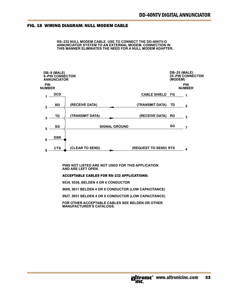
FIG. 8 WIRING DIAGRAM: NULL MODEM CABLE
RS–232 NULL MODEM CABLE. USE TO CONNECT THE DD-40NTV-OANNUNCIATOR SYSTEM TO AN EXTERNAL MODEM. CONNECTION INTHIS MANNER ELIMINATES THE NEED FOR A NULL MODEM ADAPTER.
PINS NOT LISTED ARE NOT USED FOR THIS APPLICATIONAND ARE LEFT OPEN.
ACCEPTABLE CABLES FOR RS–232 APPLICATIONS:
9534, 9536, BELDEN 4 OR 6 CONDUCTOR
9609, 9611 BELDEN 4 OR 6 CONDUCTOR (LOW CAPACITANCE)
9927, 9931 BELDEN 4 OR 6 CONDUCTOR (LOW CAPACITANCE)
FOR OTHER ACCEPTABLE CABLES SEE BELDEN OR OTHERMANUFACTURER’S CATALOGS.
DB–9 (MALE)9–PIN CONNECTORANNUNCIATOR
DB–25 (MALE)25–PIN CONNECTOR(MODEM)
(RECEIVE DATA)
(TRANSMIT DATA)
(CLEAR TO SEND)
CABLE SHIELD FG
(TRANSMIT DATA) TD
(RECEIVE DATA) RD
SG
(REQUEST TO SEND) RTS
PINNUMBER
1
2
3
7
4
1
2
3
5
6
8
DCD
RD
TD
SG
DSR
CTS
PINNUMBER
SIGNAL GROUND
FORM DD-40NTV II 5-0634
DD-40NTV DIGITAL ANNUNCIATOR
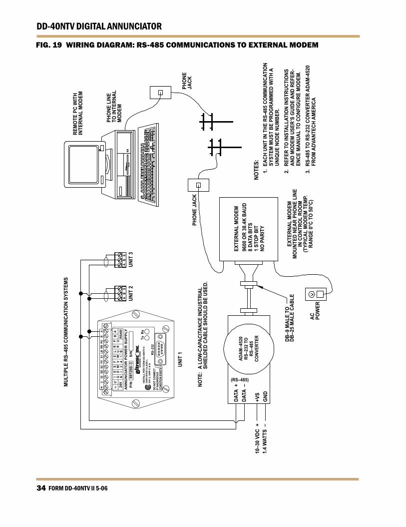
FIG. 9 WIRING DIAGRAM: RS-48 COMMUNICATIONS TO EXTERNAL MODEM
RS–2
32DO
NOT
CON
NECT
IF H
AZAR
DOUS
COND
ITIO
N EX
ISTS
Tx R
x
P/N
69
1200
–3
S/N
GIR
AR
D, O
HIO
INST
ALL
PER
FO
RM
DD
-40N
TV II
CE
RTI
FIE
D C
LAS
S I,
DIV
2, G
RP
C &
D
AN
NU
NC
IATO
R P
OW
ER
SU
PP
LY24
VI G N
B A
RS48
5
P UR R
L U B
S W 1
F V A
S W 2
S D I
+
IG
SD S
2 F
V S
1 L
B R
R P
U B
A
NOTE
S:
1. E
ACH
UNIT
IN T
HE R
S-48
5 CO
MM
UNIC
ATIO
N SY
STEM
MUS
T BE
PRO
GRA
MM
ED W
ITH
A UN
IQUE
NO
DE N
UMBE
R.
2.
REF
ER T
O IN
STAL
LATI
ON
INST
RUCT
IONS
AN
D M
ODE
M U
SER’
S G
UIDE
AND
REF
ER-
ENCE
MAN
UAL
TO C
ONF
IGUR
E M
ODE
M.
3.
RS-
485
TO R
S-23
2 CO
NVER
TER
ADAM
-452
0 FR
OM
ADV
ANTE
CH A
MER
ICA
EXTE
RNAL
MO
DEM
MO
UNTE
D NE
AR P
HONE
LIN
EIN
CO
NTRO
L RO
OM
(TYP
ICAL
MO
DEM
TEM
P.RA
NGE
0°C
TO 5
0°C)
ADAM
–452
0RS
–232
TO
RS–4
85CO
NVER
TER
AC POW
ER
DB–9
MAL
E TO
DB–2
5 M
ALE
CABL
E
10–3
0 VD
C +
1.4
WAT
TS –
UNIT
1
MUL
TIPL
E RS
–485
CO
MM
UNIC
ATIO
N SY
STEM
S
UNIT
2A
B
SA
B
S
UNIT
3
PHO
NE J
ACK
PHO
NEJA
CK
PHO
NE L
INE
TO IN
TERN
ALM
ODE
M
REM
OTE
PC
WIT
HIN
TERN
AL M
ODE
M
DATA
+DA
TA –
+VS
GND
NOTE
: A
LOW
-CAP
ACIT
ANCE
INDU
STRI
AL
SHIE
LDED
CAB
LE S
HOUL
D BE
USE
D.
EXTE
RNAL
MO
DEM
9600
OR
38.4
K BA
UD8
DATA
BIT
S1
STO
P BI
TNO
PAR
ITY
www.altronicinc.com 3
DD-40NTV DIGITAL ANNUNCIATOR
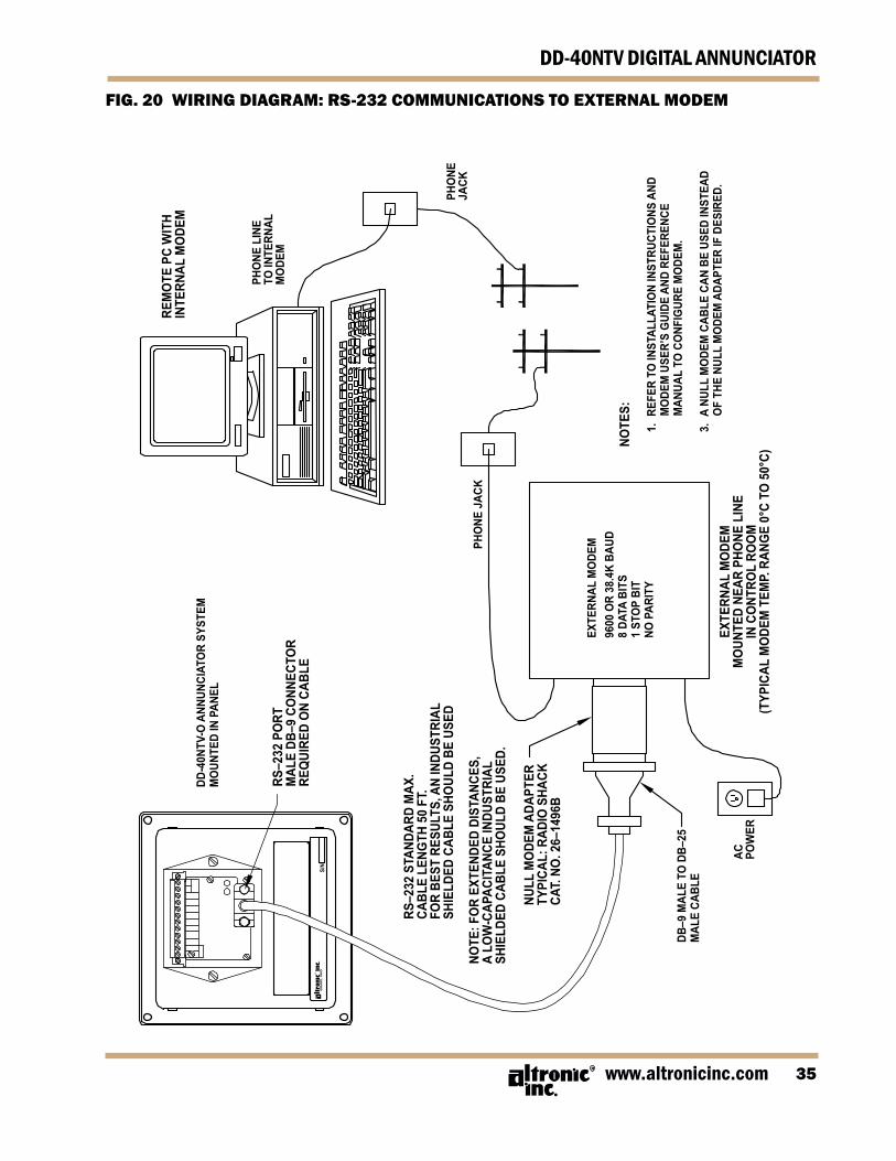
FIG. 20 WIRING DIAGRAM: RS-232 COMMUNICATIONS TO EXTERNAL MODEM
NOTE
S:
1.
REF
ER T
O IN
STAL
LATI
ON
INST
RUCT
IONS
AND
M
ODE
M U
SER’
S G
UIDE
AND
REF
EREN
CE
MAN
UAL
TO C
ONF
IGUR
E M
ODE
M.
3.
A N
ULL
MO
DEM
CAB
LE C
AN B
E US
ED IN
STEA
D O
F TH
E NU
LL M
ODE
M A
DAPT
ER IF
DES
IRED
.EX
TERN
AL M
ODE
MM
OUN
TED
NEAR
PHO
NE L
INE
IN C
ONT
ROL
ROO
M(T
YPIC
AL M
ODE
M T
EMP.
RAN
GE
0°C
TO 5
0°C)
DD-4
0NTV
-O A
NNUN
CIAT
OR
SYST
EMM
OUN
TED
IN P
ANEL
RS–2
32 S
TAND
ARD
MAX
.CA
BLE
LENG
TH 5
0 FT
.FO
R BE
ST R
ESUL
TS, A
N IN
DUST
RIAL
SHIE
LDED
CAB
LE S
HOUL
D BE
USE
D
NULL
MO
DEM
ADA
PTER
TYPI
CAL:
RAD
IO S
HACK
CAT.
NO
. 26–
1496
B
NOTE
: FO
R EX
TEND
ED D
ISTA
NCES
,A
LOW
-CAP
ACIT
ANCE
INDU
STRI
ALSH
IELD
ED C
ABLE
SHO
ULD
BE U
SED.
RS–2
32 P
ORT
MAL
E DB
–9 C
ONN
ECTO
RRE
QUI
RED
ON
CABL
ES/
N
AC POW
ER
DB–9
MAL
E TO
DB–
25
MAL
E CA
BLE
PHO
NE J
ACK
PHO
NEJA
CK
PHO
NE L
INE
TO IN
TERN
ALM
ODE
M
REM
OTE
PC
WIT
HIN
TERN
AL M
ODE
M
GIR
AR
D, O
HIO
EXTE
RNAL
MO
DEM
9600
OR
38.4
K BA
UD8
DATA
BIT
S1
STO
P BI
TNO
PAR
ITY