installation guide - user manual search engine · installation guide to rru3942&rru3642...
TRANSCRIPT
RRU3942&RRU3642
Installation Guide
Issue 07
Date 2013-12-30
HUAWEI TECHNOLOGIES CO., LTD.
Copyright © Huawei Technologies Co., Ltd. 2013. All rights reserved.
No part of this document may be reproduced or transmitted in any form or by any means without prior writtenconsent of Huawei Technologies Co., Ltd. Trademarks and Permissions
and other Huawei trademarks are trademarks of Huawei Technologies Co., Ltd.All other trademarks and trade names mentioned in this document are the property of their respective holders. NoticeThe purchased products, services and features are stipulated by the contract made between Huawei and thecustomer. All or part of the products, services and features described in this document may not be within thepurchase scope or the usage scope. Unless otherwise specified in the contract, all statements, information,and recommendations in this document are provided "AS IS" without warranties, guarantees or representationsof any kind, either express or implied.
The information in this document is subject to change without notice. Every effort has been made in thepreparation of this document to ensure accuracy of the contents, but all statements, information, andrecommendations in this document do not constitute a warranty of any kind, express or implied.
Huawei Technologies Co., Ltd.Address: Huawei Industrial Base
Bantian, LonggangShenzhen 518129People's Republic of China
Website: http://www.huawei.com
Email: [email protected]
Issue 07 (2013-12-30) Huawei Proprietary and ConfidentialCopyright © Huawei Technologies Co., Ltd.
i
About This Document
PurposeThis document describes the process of installing DC RRU3942 and RRU3642 (referred to asRRU in this document).
Product VersionThe following table lists the product version related to this document for RRU3942.
Product Name Product Version
DBS3900 V100R004C00 and later versions
DBS3900 GSM V100R013C00 and later versions
DBS3900 WCDMA V200R013C00 and later versions
DBS3900 LTE V100R005C00 and later versions
The following table lists the product version related to this document for RRU3642.
Product Name Product Version
DBS3900 V100R008C00 and later versions
DBS3900 LTE V100R006C00 and later versions
Intended AudienceThis document is intended for:
Base station installation engineers
Organization1 Changes in the RRU3942&RRU3642 Installation Guide
RRU3942&RRU3642Installation Guide About This Document
Issue 07 (2013-12-30) Huawei Proprietary and ConfidentialCopyright © Huawei Technologies Co., Ltd.
ii
This chapter describes the changes in the RRU3942&RRU3642 Installation Guide.
2 Installation Preparations
This chapter describes the reference documents, tools, and instruments that must be ready beforethe installation. In addition, it specifies the skills and prerequisites that installation engineersmust have.
3 Information About the Installation
Before installing an RRU, you must be familiar with its exterior, ports, indicators, installationoptions and installation clearance requirements.
4 Unpacking the Equipment
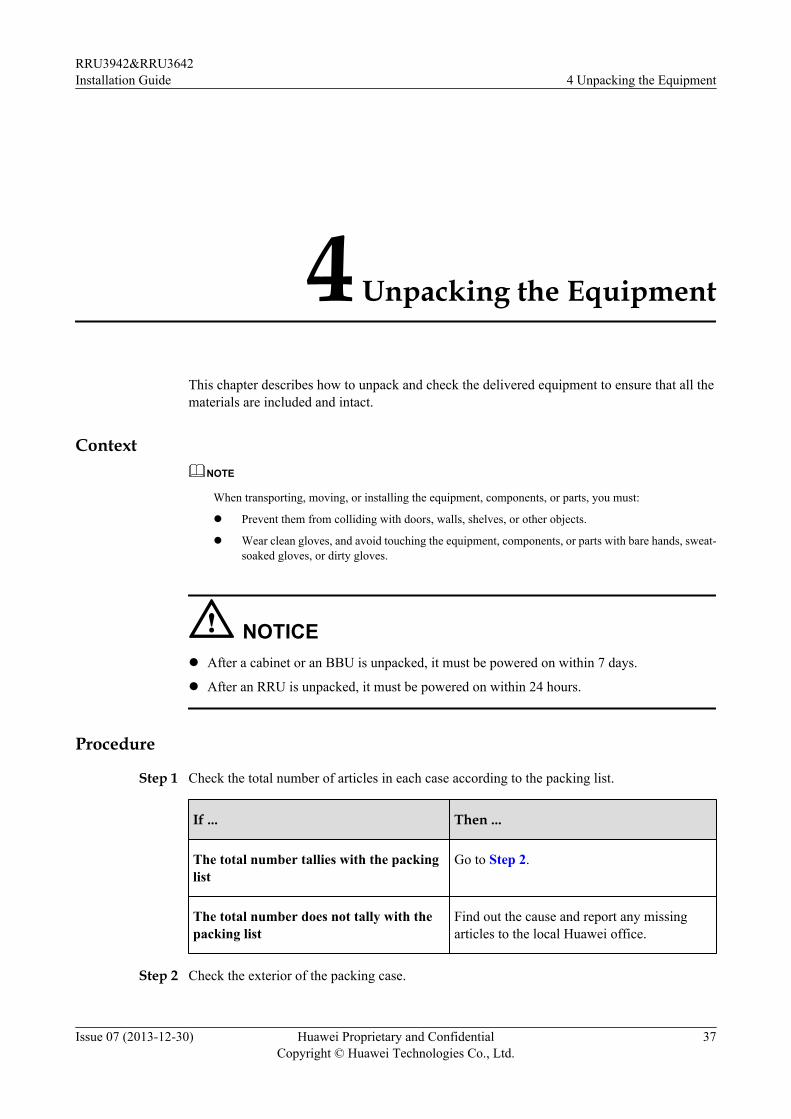
This chapter describes how to unpack and check the delivered equipment to ensure that all thematerials are included and intact.
5 Installation Process
The installation process involves installing an RRU and RRU cables, checking the RRUhardware installation, and powering on the RRU.
6 Hoisting an RRU and Related Cables onto a Tower
This section describes the procedure for hoisting an RRU and related cables onto a tower andthe precautions that must be taken.
7 Installing the RRU
This chapter describes the procedure for installing the RRU. The procedure for installing theRRU varies depending on installation options.
8 Installing RRU Cables
This chapter describes the procedure for installing RRU cables.
9 Checking the RRU Hardware Installation
After an RRU is installed, check the hardware installation.
10 Powering On an RRU
After all the devices are installed, check the power-on status of an RRU.
11 Appendix
This section describes the procedure for adding an easy power receptacle (pressfit type)connector.
ConventionsSymbol Conventions
The symbols that may be found in this document are defined as follows.
RRU3942&RRU3642Installation Guide About This Document
Issue 07 (2013-12-30) Huawei Proprietary and ConfidentialCopyright © Huawei Technologies Co., Ltd.
iii
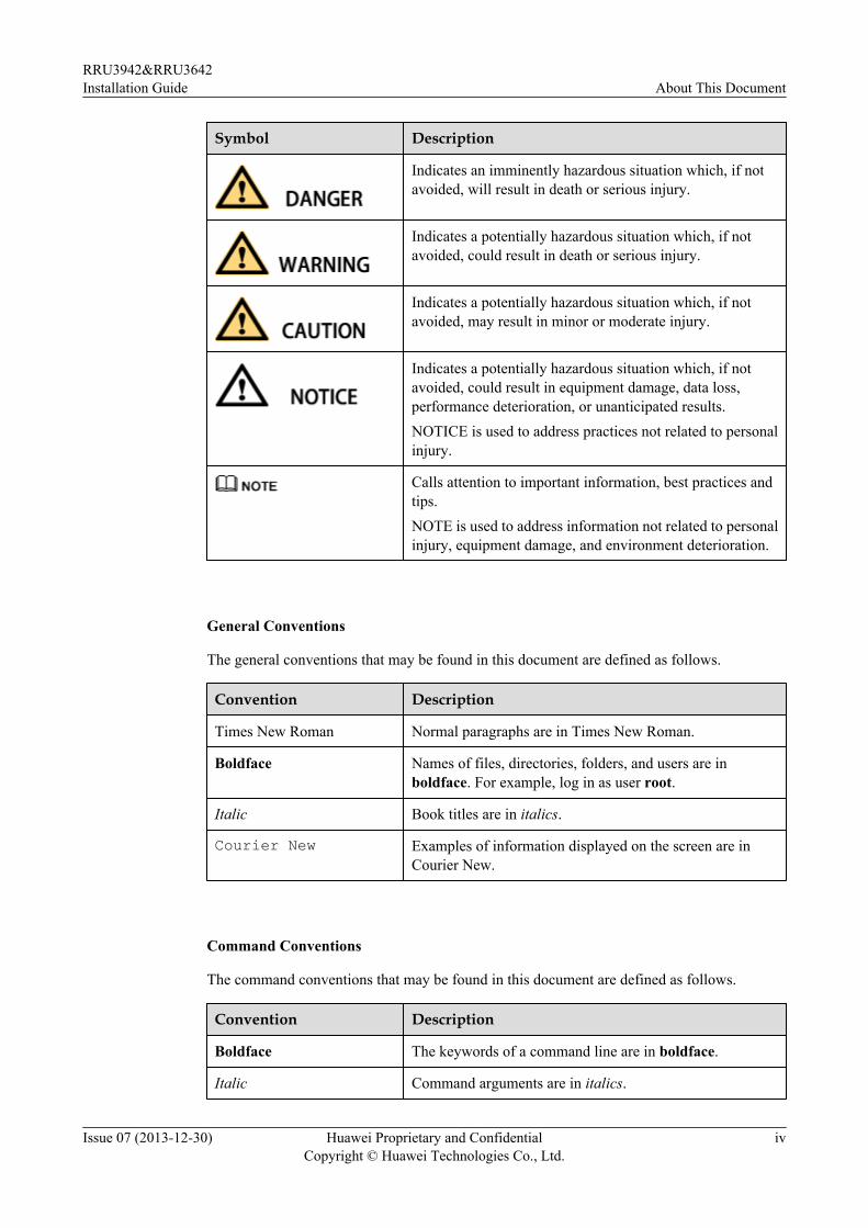
Symbol Description
Indicates an imminently hazardous situation which, if notavoided, will result in death or serious injury.
Indicates a potentially hazardous situation which, if notavoided, could result in death or serious injury.
Indicates a potentially hazardous situation which, if notavoided, may result in minor or moderate injury.
Indicates a potentially hazardous situation which, if notavoided, could result in equipment damage, data loss,performance deterioration, or unanticipated results.NOTICE is used to address practices not related to personalinjury.
Calls attention to important information, best practices andtips.NOTE is used to address information not related to personalinjury, equipment damage, and environment deterioration.
General Conventions
The general conventions that may be found in this document are defined as follows.
Convention Description
Times New Roman Normal paragraphs are in Times New Roman.
Boldface Names of files, directories, folders, and users are inboldface. For example, log in as user root.
Italic Book titles are in italics.
Courier New Examples of information displayed on the screen are inCourier New.
Command Conventions
The command conventions that may be found in this document are defined as follows.
Convention Description
Boldface The keywords of a command line are in boldface.
Italic Command arguments are in italics.
RRU3942&RRU3642Installation Guide About This Document
Issue 07 (2013-12-30) Huawei Proprietary and ConfidentialCopyright © Huawei Technologies Co., Ltd.
iv
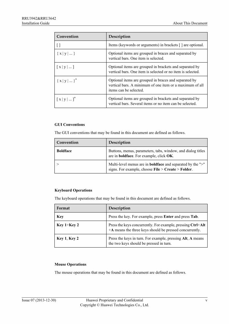
Convention Description
[ ] Items (keywords or arguments) in brackets [ ] are optional.
{ x | y | ... } Optional items are grouped in braces and separated byvertical bars. One item is selected.
[ x | y | ... ] Optional items are grouped in brackets and separated byvertical bars. One item is selected or no item is selected.
{ x | y | ... }* Optional items are grouped in braces and separated byvertical bars. A minimum of one item or a maximum of allitems can be selected.
[ x | y | ... ]* Optional items are grouped in brackets and separated byvertical bars. Several items or no item can be selected.
GUI Conventions
The GUI conventions that may be found in this document are defined as follows.
Convention Description
Boldface Buttons, menus, parameters, tabs, window, and dialog titlesare in boldface. For example, click OK.
> Multi-level menus are in boldface and separated by the ">"signs. For example, choose File > Create > Folder.
Keyboard Operations
The keyboard operations that may be found in this document are defined as follows.
Format Description
Key Press the key. For example, press Enter and press Tab.
Key 1+Key 2 Press the keys concurrently. For example, pressing Ctrl+Alt+A means the three keys should be pressed concurrently.
Key 1, Key 2 Press the keys in turn. For example, pressing Alt, A meansthe two keys should be pressed in turn.
Mouse Operations
The mouse operations that may be found in this document are defined as follows.
RRU3942&RRU3642Installation Guide About This Document
Issue 07 (2013-12-30) Huawei Proprietary and ConfidentialCopyright © Huawei Technologies Co., Ltd.
v
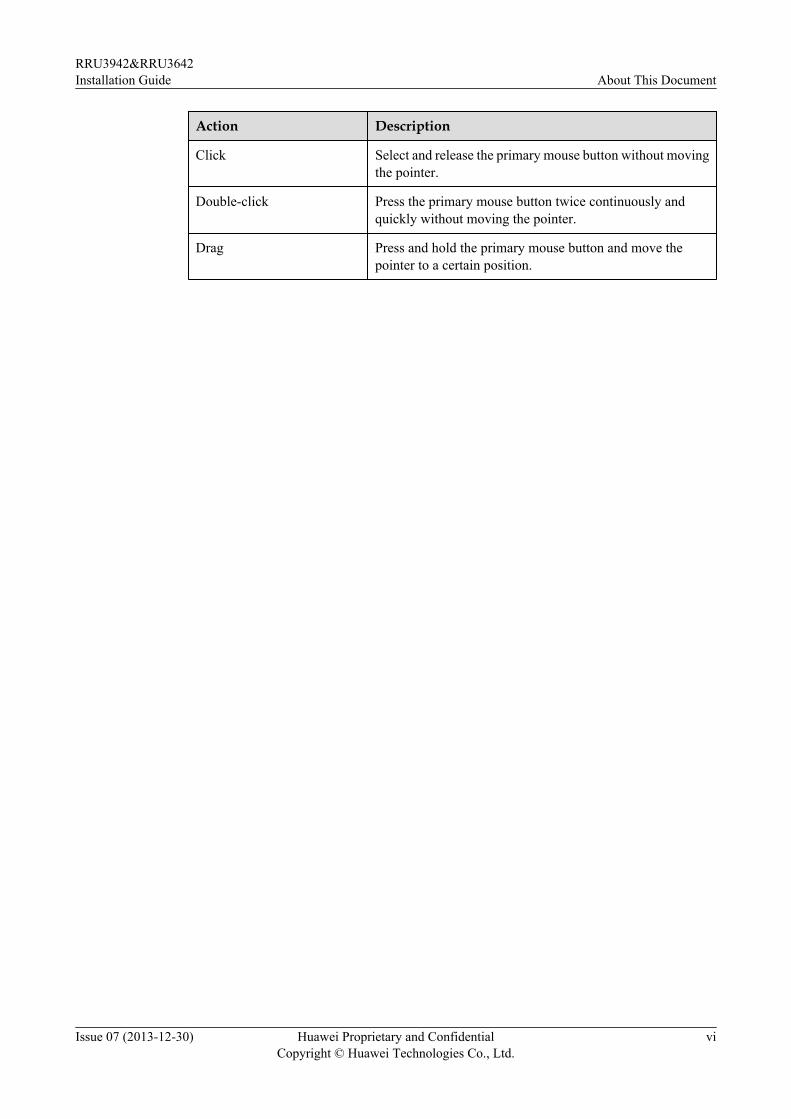
Action Description
Click Select and release the primary mouse button without movingthe pointer.
Double-click Press the primary mouse button twice continuously andquickly without moving the pointer.
Drag Press and hold the primary mouse button and move thepointer to a certain position.
RRU3942&RRU3642Installation Guide About This Document
Issue 07 (2013-12-30) Huawei Proprietary and ConfidentialCopyright © Huawei Technologies Co., Ltd.
vi
Contents
About This Document.....................................................................................................................ii
1 Changes in the RRU3942&RRU3642 Installation Guide.......................................................1
2 Installation Preparations..............................................................................................................52.1 Reference Documents.....................................................................................................................................................62.2 Tools and Instruments....................................................................................................................................................62.3 Skills and Requirements for Onsite Personnel...............................................................................................................8
3 Information About the Installation...........................................................................................93.1 RRU Exterior................................................................................................................................................................103.2 RRU Ports.....................................................................................................................................................................103.3 RRU Indicators.............................................................................................................................................................183.4 Installation Scenarios....................................................................................................................................................203.5 Installation Clearance Requirements of an RRU..........................................................................................................283.5.1 Clearance for a Single RRU......................................................................................................................................283.5.2 Clearances for Three or More RRUs.........................................................................................................................303.5.3 Installation Spacing Between RRUs..........................................................................................................................34
4 Unpacking the Equipment.........................................................................................................37
5 Installation Process.....................................................................................................................39
6 Hoisting an RRU and Related Cables onto a Tower............................................................406.1 Hoisting an RRU onto a Tower....................................................................................................................................416.2 Hoisting Fiber Optic Cables onto a Tower...................................................................................................................456.3 Hoisting Power Cables onto a Tower...........................................................................................................................47
7 Installing the RRU.......................................................................................................................507.1 Mounting Kits for an RRU...........................................................................................................................................517.2 Installing the RRU on a Pole........................................................................................................................................517.2.1 Installing a Single RRU.............................................................................................................................................527.2.2 Installing Two RRUs.................................................................................................................................................557.2.3 Installing Three or More RRUs.................................................................................................................................607.3 Installing the RRU on U-steel......................................................................................................................................647.4 Installing the RRU on Angle Steel...............................................................................................................................687.5 Installing the RRU on a Wall.......................................................................................................................................72
RRU3942&RRU3642Installation Guide Contents
Issue 07 (2013-12-30) Huawei Proprietary and ConfidentialCopyright © Huawei Technologies Co., Ltd.
vii
7.6 Installing an RRU on an IFS06.....................................................................................................................................76
8 Installing RRU Cables................................................................................................................828.1 Cabling Requirements..................................................................................................................................................848.2 Cable Connections........................................................................................................................................................908.3 Installation Process.......................................................................................................................................................948.4 RRU Cable List............................................................................................................................................................958.5 Installing an RRU PGND Cable...................................................................................................................................978.6 Installing an RRU RF Jumper......................................................................................................................................988.7 Installing an Inter-RRU RF Cable..............................................................................................................................1028.8 Installing an RRU AISG Multi-Wire Cable and AISG Extension Cable...................................................................1038.9 Opening the Cover Plate of an RRU Cabling Cavity.................................................................................................1058.10 Installing an RRU Power Cable................................................................................................................................1078.11 Installing a CPRI Fiber Optic Cable.........................................................................................................................1098.12 Installing an RRU Alarm Cable................................................................................................................................1118.13 Closing the Cover Plate of an RRU Cabling Cavity................................................................................................111
9 Checking the RRU Hardware Installation............................................................................114
10 Powering On an RRU.............................................................................................................115
11 Appendix...................................................................................................................................11711.1 Adding a Tool-Less Female Connector (Pressfit Type) to the RRU Power Cable on the RRU Side......................118
RRU3942&RRU3642Installation Guide Contents
Issue 07 (2013-12-30) Huawei Proprietary and ConfidentialCopyright © Huawei Technologies Co., Ltd.
viii
1 Changes in the RRU3942&RRU3642Installation Guide
This chapter describes the changes in the RRU3942&RRU3642 Installation Guide.
07 (2013-12-30)This is the seventh official release.
Compared with issue 06 (2013-12-23), this issue includes the following change:
Topic Change Description
3.4 Installation Scenarios Modified the figure showing the U-steelspecifications.
Compared with issue 06 (2013-12-23), this issue does not include any new information and noinformation is deleted from this issue.
06 (2013-12-23)This is the sixth official release.
Compared with issue 05 (2013-06-26), this issue includes the following change:
Topic Change Description
6.1 Hoisting an RRU onto a Tower Optimized the procedure for hoisting an RRUonto a Tower.
Compared with issue 05 (2013-06-26), this issue does not include any new information and noinformation is deleted from this issue.
RRU3942&RRU3642Installation Guide 1 Changes in the RRU3942&RRU3642 Installation Guide
Issue 07 (2013-12-30) Huawei Proprietary and ConfidentialCopyright © Huawei Technologies Co., Ltd.
1
05 (2013-06-26)
This is the fifth official release.
Compared with issue 04 (2013-04-28), this issue includes the following change:
Topic Change Description
8.10 Installing an RRU Power Cable Added the power device DCDU-12B for theRRU.
Compared with issue 04 (2013-04-28), this issue does not include any new information and noinformation is deleted from this issue.
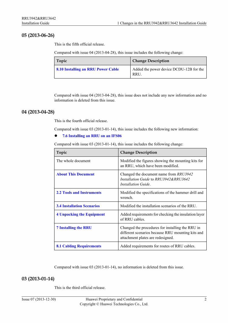
04 (2013-04-28)
This is the fourth official release.
Compared with issue 03 (2013-01-14), this issue includes the following new information:
l 7.6 Installing an RRU on an IFS06
Compared with issue 03 (2013-01-14), this issue includes the following change:
Topic Change Description
The whole document Modified the figures showing the mounting kits foran RRU, which have been modified.
About This Document Changed the document name from RRU3942Installation Guide to RRU3942&RRU3642Installation Guide.
2.2 Tools and Instruments Modified the specifications of the hammer drill andwrench.
3.4 Installation Scenarios Modified the installation scenarios of the RRU.
4 Unpacking the Equipment Added requirements for checking the insulation layerof RRU cables.
7 Installing the RRU Changed the procedures for installing the RRU indifferent scenarios because RRU mounting kits andattachment plates are redesigned.
8.1 Cabling Requirements Added requirements for routes of RRU cables.
Compared with issue 03 (2013-01-14), no information is deleted from this issue.
03 (2013-01-14)
This is the third official release.
RRU3942&RRU3642Installation Guide 1 Changes in the RRU3942&RRU3642 Installation Guide
Issue 07 (2013-12-30) Huawei Proprietary and ConfidentialCopyright © Huawei Technologies Co., Ltd.
2
Compared with issue 02 (2012-09-15), this issue does not include any new information.
Compared with issue 02 (2012-09-15), this issue includes the following change:
Topic Change Description
8.10 Installing an RRU Power Cable Added the attention for installing the RRUpower cable.
Compared with issue 02 (2012-09-15), no information is deleted from this issue.
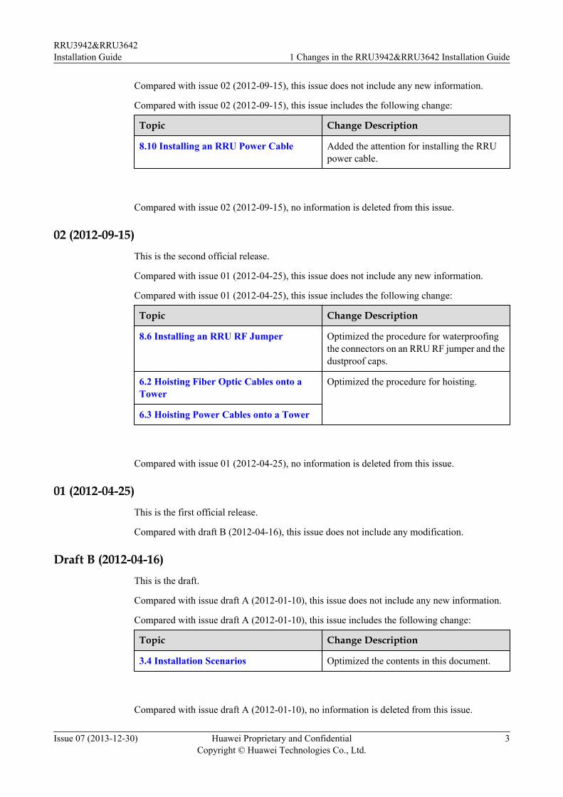
02 (2012-09-15)This is the second official release.
Compared with issue 01 (2012-04-25), this issue does not include any new information.
Compared with issue 01 (2012-04-25), this issue includes the following change:
Topic Change Description
8.6 Installing an RRU RF Jumper Optimized the procedure for waterproofingthe connectors on an RRU RF jumper and thedustproof caps.
6.2 Hoisting Fiber Optic Cables onto aTower
Optimized the procedure for hoisting.
6.3 Hoisting Power Cables onto a Tower
Compared with issue 01 (2012-04-25), no information is deleted from this issue.
01 (2012-04-25)This is the first official release.
Compared with draft B (2012-04-16), this issue does not include any modification.
Draft B (2012-04-16)This is the draft.
Compared with issue draft A (2012-01-10), this issue does not include any new information.
Compared with issue draft A (2012-01-10), this issue includes the following change:
Topic Change Description
3.4 Installation Scenarios Optimized the contents in this document.
Compared with issue draft A (2012-01-10), no information is deleted from this issue.
RRU3942&RRU3642Installation Guide 1 Changes in the RRU3942&RRU3642 Installation Guide
Issue 07 (2013-12-30) Huawei Proprietary and ConfidentialCopyright © Huawei Technologies Co., Ltd.
3

Draft A (2012-01-10)This is a draft.
RRU3942&RRU3642Installation Guide 1 Changes in the RRU3942&RRU3642 Installation Guide
Issue 07 (2013-12-30) Huawei Proprietary and ConfidentialCopyright © Huawei Technologies Co., Ltd.
4
2 Installation Preparations
About This Chapter
This chapter describes the reference documents, tools, and instruments that must be ready beforethe installation. In addition, it specifies the skills and prerequisites that installation engineersmust have.
2.1 Reference DocumentsBefore the installation, you must be familiar with reference documents.
2.2 Tools and InstrumentsYou must prepare the following tools and instruments before the installation.
2.3 Skills and Requirements for Onsite PersonnelOnsite personnel must be qualified and trained. Before performing any operation, onsitepersonnel must be familiar with correct operation methods and safety precautions.
RRU3942&RRU3642Installation Guide 2 Installation Preparations
Issue 07 (2013-12-30) Huawei Proprietary and ConfidentialCopyright © Huawei Technologies Co., Ltd.
5
2.1 Reference DocumentsBefore the installation, you must be familiar with reference documents.
The following reference documents are required during RRU installation:l RRU3942&RRU3642 Hardware Descriptionl DBS3900 Installation Guidel OCB User Guidel OCB-01M User Guide
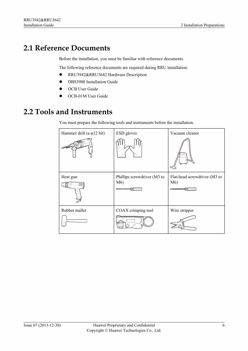
2.2 Tools and InstrumentsYou must prepare the following tools and instruments before the installation.
Hammer drill (a φ12 bit) ESD gloves Vacuum cleaner
Heat gun Phillips screwdriver (M3 toM6)
Flat-head screwdriver (M3 toM6)
Rubber mallet COAX crimping tool Wire stripper
RRU3942&RRU3642Installation Guide 2 Installation Preparations
Issue 07 (2013-12-30) Huawei Proprietary and ConfidentialCopyright © Huawei Technologies Co., Ltd.
6
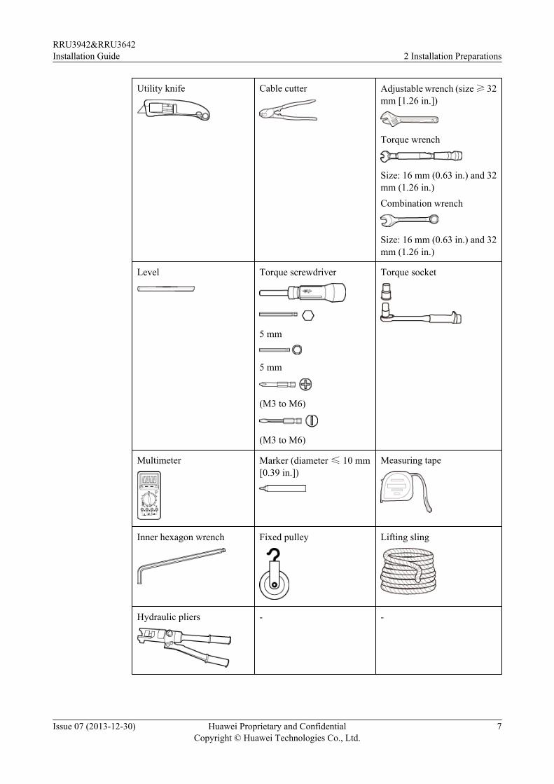
Utility knife Cable cutter Adjustable wrench (size ≥ 32mm [1.26 in.])
Torque wrench
Size: 16 mm (0.63 in.) and 32mm (1.26 in.)Combination wrench
Size: 16 mm (0.63 in.) and 32mm (1.26 in.)
Level Torque screwdriver
5 mm
5 mm
(M3 to M6)
(M3 to M6)
Torque socket
Multimeter Marker (diameter ≤ 10 mm[0.39 in.])
Measuring tape
Inner hexagon wrench Fixed pulley Lifting sling
Hydraulic pliers - -
RRU3942&RRU3642Installation Guide 2 Installation Preparations
Issue 07 (2013-12-30) Huawei Proprietary and ConfidentialCopyright © Huawei Technologies Co., Ltd.
7
2.3 Skills and Requirements for Onsite PersonnelOnsite personnel must be qualified and trained. Before performing any operation, onsitepersonnel must be familiar with correct operation methods and safety precautions.
Before the installation, pay attention to the following items:
l The customer's technical engineers must be trained by Huawei and be familiar with theproper installation and operation methods.
l The number of onsite personnel depends on the engineering schedule and installationenvironment. Generally, only three to five onsite personnel are necessary.
RRU3942&RRU3642Installation Guide 2 Installation Preparations
Issue 07 (2013-12-30) Huawei Proprietary and ConfidentialCopyright © Huawei Technologies Co., Ltd.
8
3 Information About the Installation
About This Chapter
Before installing an RRU, you must be familiar with its exterior, ports, indicators, installationoptions and installation clearance requirements.
3.1 RRU ExteriorThis section describes the exterior and dimensions of an RRU.
3.2 RRU PortsThis section describes ports on the RRU panels. An RRU has a bottom panel, cabling cavitypanel, and indicator panel.
3.3 RRU IndicatorsThis section describes six indicators on an RRU. They indicate the running status.
3.4 Installation ScenariosAn RRU can be installed on a pole, U-steel, angle steel, wall, or IFS06. Installation scenariosmust meet heat-dissipation and waterproofing requirements of the RRU.
3.5 Installation Clearance Requirements of an RRUThis section describes the requirements for the installation clearance of a single RRU andmultiple RRUs and the requirements for the installation spacing between RRUs.
RRU3942&RRU3642Installation Guide 3 Information About the Installation
Issue 07 (2013-12-30) Huawei Proprietary and ConfidentialCopyright © Huawei Technologies Co., Ltd.
9
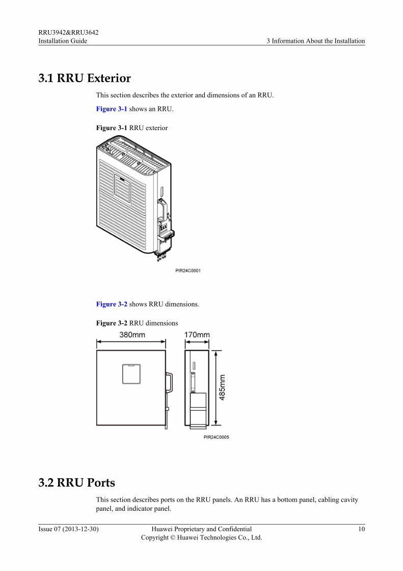
3.1 RRU ExteriorThis section describes the exterior and dimensions of an RRU.
Figure 3-1 shows an RRU.
Figure 3-1 RRU exterior
Figure 3-2 shows RRU dimensions.
Figure 3-2 RRU dimensions
3.2 RRU PortsThis section describes ports on the RRU panels. An RRU has a bottom panel, cabling cavitypanel, and indicator panel.
RRU3942&RRU3642Installation Guide 3 Information About the Installation
Issue 07 (2013-12-30) Huawei Proprietary and ConfidentialCopyright © Huawei Technologies Co., Ltd.
10
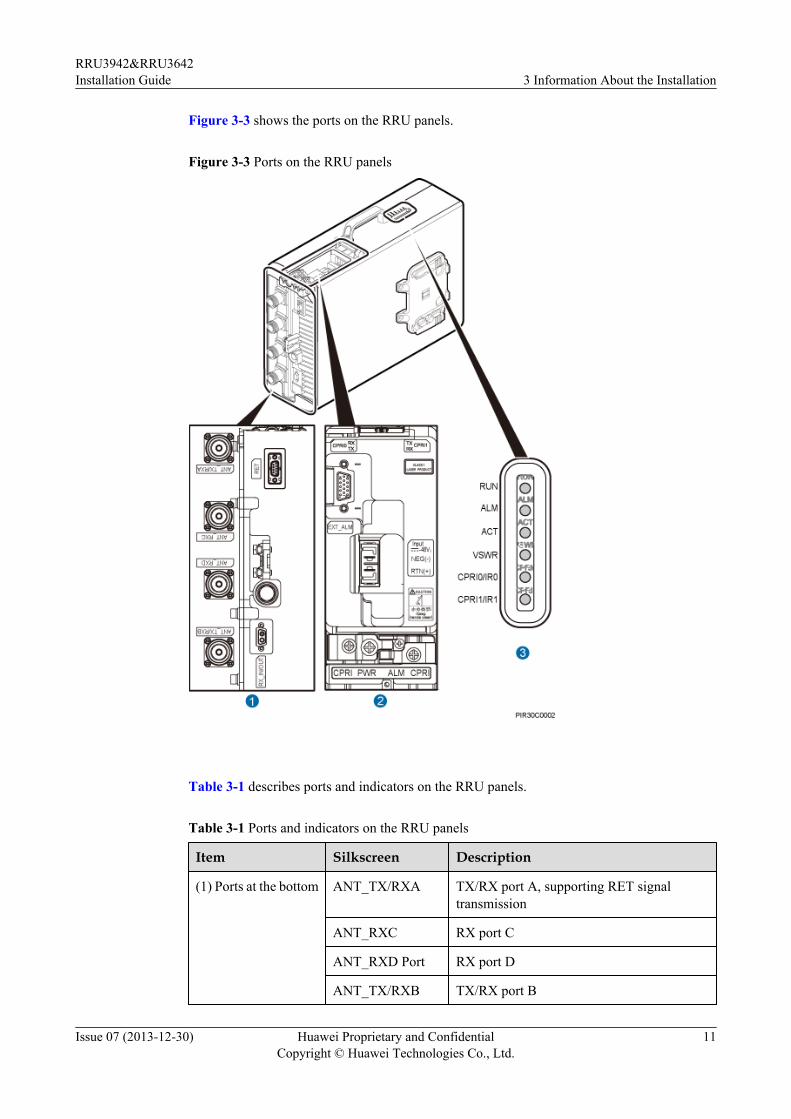
Figure 3-3 shows the ports on the RRU panels.
Figure 3-3 Ports on the RRU panels
Table 3-1 describes ports and indicators on the RRU panels.
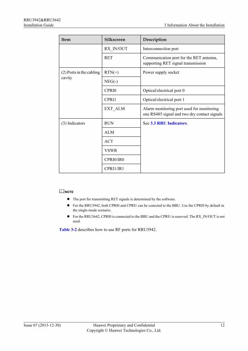
Table 3-1 Ports and indicators on the RRU panels
Item Silkscreen Description
(1) Ports at the bottom ANT_TX/RXA TX/RX port A, supporting RET signaltransmission
ANT_RXC RX port C
ANT_RXD Port RX port D
ANT_TX/RXB TX/RX port B
RRU3942&RRU3642Installation Guide 3 Information About the Installation
Issue 07 (2013-12-30) Huawei Proprietary and ConfidentialCopyright © Huawei Technologies Co., Ltd.
11
Item Silkscreen Description
RX_IN/OUT Interconnection port
RET Communication port for the RET antenna,supporting RET signal transmission
(2) Ports in the cablingcavity
RTN(+) Power supply socket
NEG(-)
CPRI0 Optical/electrical port 0
CPRI1 Optical/electrical port 1
EXT_ALM Alarm monitoring port used for monitoringone RS485 signal and two dry contact signals
(3) Indicators RUN See 3.3 RRU Indicators.
ALM
ACT
VSWR
CPRI0/IR0
CPRI1/IR1
NOTE
l The port for transmitting RET signals is determined by the software.
l For the RRU3942, both CPRI0 and CPRI1 can be conected to the BBU. Use the CPRI0 by default inthe single-mode scenario.
l For the RRU3642, CPRI0 is connected to the BBU and the CPRI1 is reserved. The RX_IN/OUT is notused.
Table 3-2 describes how to use RF ports for RRU3942.
RRU3942&RRU3642Installation Guide 3 Information About the Installation
Issue 07 (2013-12-30) Huawei Proprietary and ConfidentialCopyright © Huawei Technologies Co., Ltd.
12
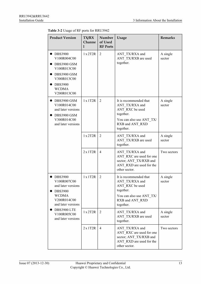
Table 3-2 Usage of RF ports for RRU3942
Product Version TX/RXChannel
Numberof UsedRF Ports
Usage Remarks
l DBS3900V100R004C00
l DBS3900 GSMV100R013C00
l DBS3900 GSMV300R013C00
l DBS3900WCDMAV200R013C00
1 x 2T2R 2 ANT_TX/RXA andANT_TX/RXB are usedtogether.
A singlesector
l DBS3900 GSMV100R014C00and later versions
l DBS3900 GSMV300R014C00and later versions
1 x 1T2R 2 It is recommended thatANT_TX/RXA andANT_RXC be usedtogether.You can also use ANT_TX/RXB and ANT_RXDtogether.
A singlesector
1 x 2T2R 2 ANT_TX/RXA andANT_TX/RXB are usedtogether.
A singlesector
2 x 1T2R 4 ANT_TX/RXA andANT_RXC are used for onesector; ANT_TX/RXB andANT_RXD are used for theother sector.
Two sectors
l DBS3900V100R007C00and later versions
l DBS3900WCDMAV200R014C00and later versions
l DBS3900 LTEV100R005C00and later versions
1 x 1T2R 2 It is recommended thatANT_TX/RXA andANT_RXC be usedtogether.You can also use ANT_TX/RXB and ANT_RXDtogether.
A singlesector
1 x 2T2R 2 ANT_TX/RXA andANT_TX/RXB are usedtogether.
A singlesector
2 x 1T2R 4 ANT_TX/RXA andANT_RXC are used for onesector; ANT_TX/RXB andANT_RXD are used for theother sector.
Two sectors
RRU3942&RRU3642Installation Guide 3 Information About the Installation
Issue 07 (2013-12-30) Huawei Proprietary and ConfidentialCopyright © Huawei Technologies Co., Ltd.
13
Product Version TX/RXChannel
Numberof UsedRF Ports
Usage Remarks
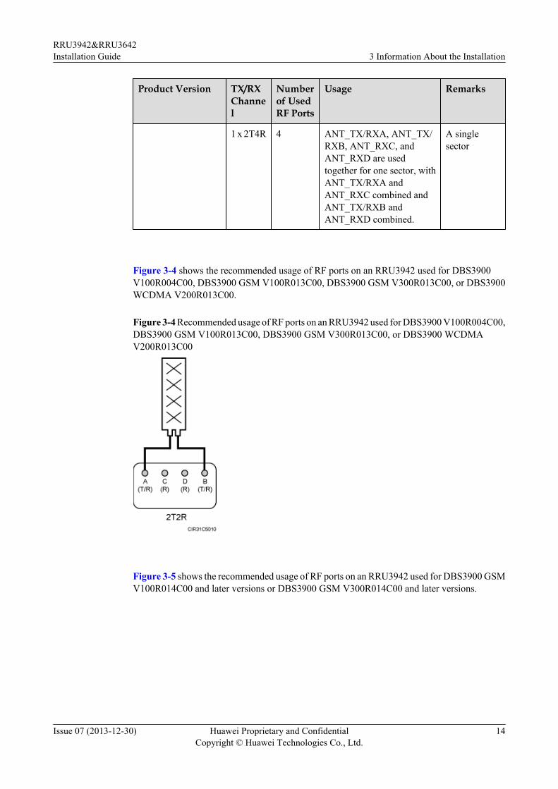
1 x 2T4R 4 ANT_TX/RXA, ANT_TX/RXB, ANT_RXC, andANT_RXD are usedtogether for one sector, withANT_TX/RXA andANT_RXC combined andANT_TX/RXB andANT_RXD combined.
A singlesector
Figure 3-4 shows the recommended usage of RF ports on an RRU3942 used for DBS3900V100R004C00, DBS3900 GSM V100R013C00, DBS3900 GSM V300R013C00, or DBS3900WCDMA V200R013C00.
Figure 3-4 Recommended usage of RF ports on an RRU3942 used for DBS3900 V100R004C00,DBS3900 GSM V100R013C00, DBS3900 GSM V300R013C00, or DBS3900 WCDMAV200R013C00
Figure 3-5 shows the recommended usage of RF ports on an RRU3942 used for DBS3900 GSMV100R014C00 and later versions or DBS3900 GSM V300R014C00 and later versions.
RRU3942&RRU3642Installation Guide 3 Information About the Installation
Issue 07 (2013-12-30) Huawei Proprietary and ConfidentialCopyright © Huawei Technologies Co., Ltd.
14
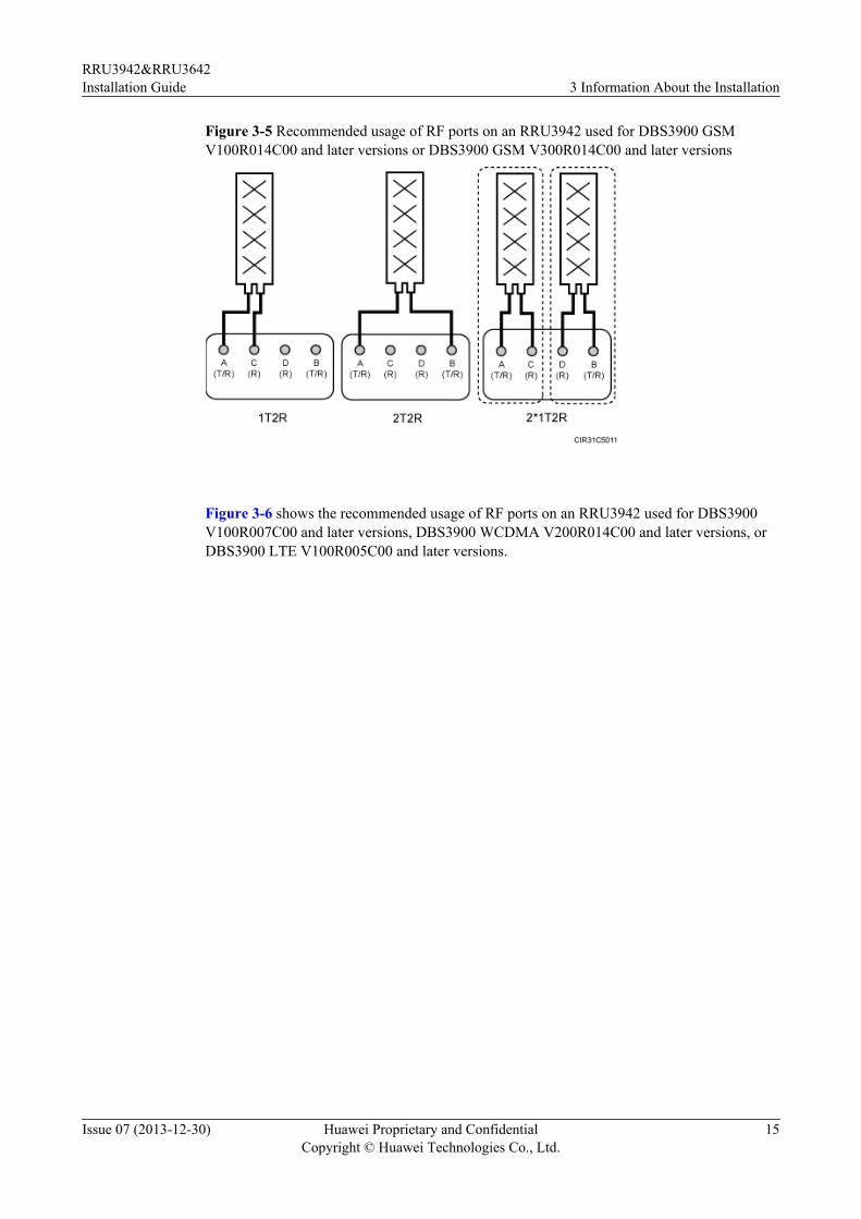
Figure 3-5 Recommended usage of RF ports on an RRU3942 used for DBS3900 GSMV100R014C00 and later versions or DBS3900 GSM V300R014C00 and later versions
Figure 3-6 shows the recommended usage of RF ports on an RRU3942 used for DBS3900V100R007C00 and later versions, DBS3900 WCDMA V200R014C00 and later versions, orDBS3900 LTE V100R005C00 and later versions.
RRU3942&RRU3642Installation Guide 3 Information About the Installation
Issue 07 (2013-12-30) Huawei Proprietary and ConfidentialCopyright © Huawei Technologies Co., Ltd.
15
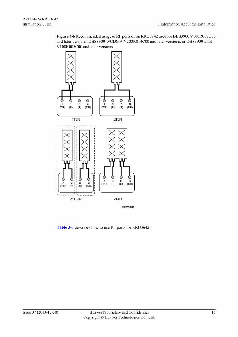
Figure 3-6 Recommended usage of RF ports on an RRU3942 used for DBS3900 V100R007C00and later versions, DBS3900 WCDMA V200R014C00 and later versions, or DBS3900 LTEV100R005C00 and later versions
Table 3-3 describes how to use RF ports for RRU3642.
RRU3942&RRU3642Installation Guide 3 Information About the Installation
Issue 07 (2013-12-30) Huawei Proprietary and ConfidentialCopyright © Huawei Technologies Co., Ltd.
16
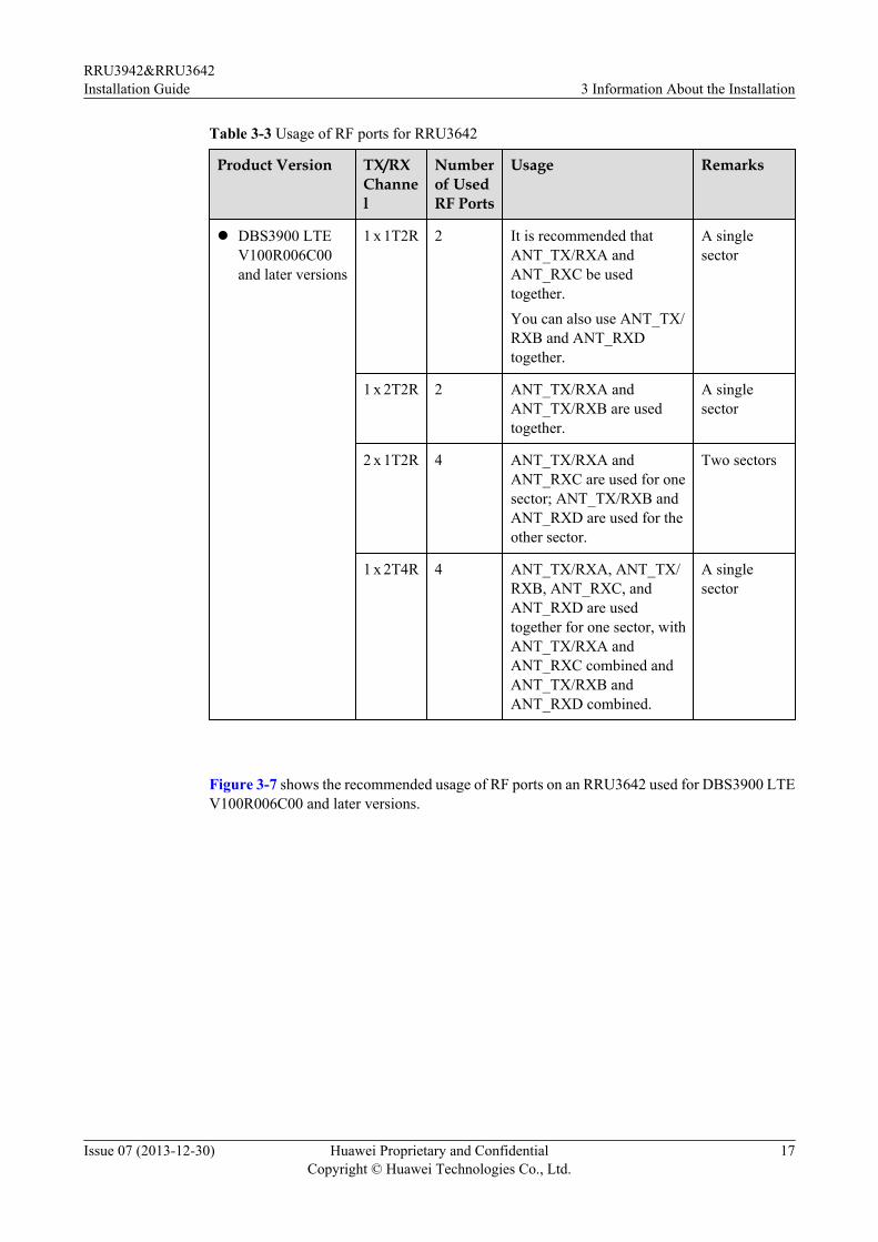
Table 3-3 Usage of RF ports for RRU3642
Product Version TX/RXChannel
Numberof UsedRF Ports
Usage Remarks
l DBS3900 LTEV100R006C00and later versions
1 x 1T2R 2 It is recommended thatANT_TX/RXA andANT_RXC be usedtogether.You can also use ANT_TX/RXB and ANT_RXDtogether.
A singlesector
1 x 2T2R 2 ANT_TX/RXA andANT_TX/RXB are usedtogether.
A singlesector
2 x 1T2R 4 ANT_TX/RXA andANT_RXC are used for onesector; ANT_TX/RXB andANT_RXD are used for theother sector.
Two sectors
1 x 2T4R 4 ANT_TX/RXA, ANT_TX/RXB, ANT_RXC, andANT_RXD are usedtogether for one sector, withANT_TX/RXA andANT_RXC combined andANT_TX/RXB andANT_RXD combined.
A singlesector
Figure 3-7 shows the recommended usage of RF ports on an RRU3642 used for DBS3900 LTEV100R006C00 and later versions.
RRU3942&RRU3642Installation Guide 3 Information About the Installation
Issue 07 (2013-12-30) Huawei Proprietary and ConfidentialCopyright © Huawei Technologies Co., Ltd.
17
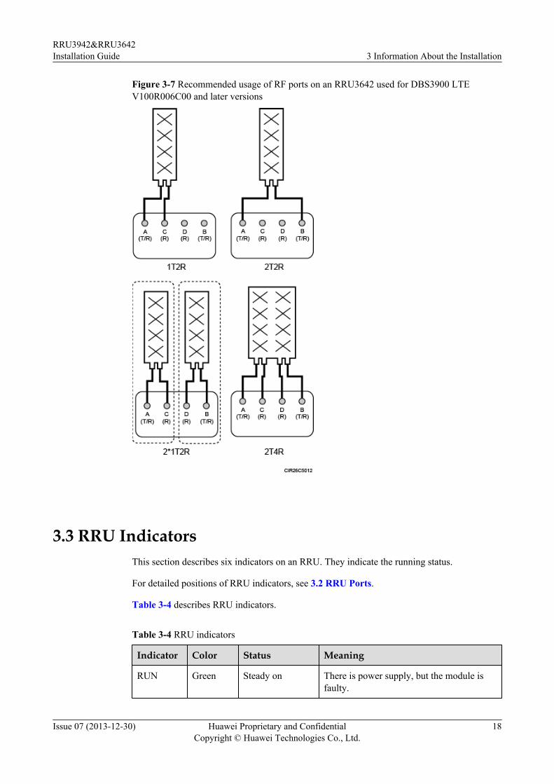
Figure 3-7 Recommended usage of RF ports on an RRU3642 used for DBS3900 LTEV100R006C00 and later versions
3.3 RRU IndicatorsThis section describes six indicators on an RRU. They indicate the running status.
For detailed positions of RRU indicators, see 3.2 RRU Ports.
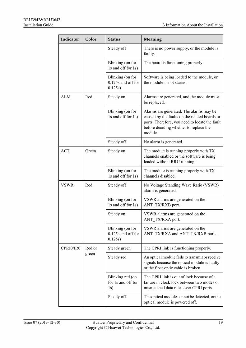
Table 3-4 describes RRU indicators.
Table 3-4 RRU indicators
Indicator Color Status Meaning
RUN Green Steady on There is power supply, but the module isfaulty.
RRU3942&RRU3642Installation Guide 3 Information About the Installation
Issue 07 (2013-12-30) Huawei Proprietary and ConfidentialCopyright © Huawei Technologies Co., Ltd.
18
Indicator Color Status Meaning
Steady off There is no power supply, or the module isfaulty.
Blinking (on for1s and off for 1s)
The board is functioning properly.
Blinking (on for0.125s and off for0.125s)
Software is being loaded to the module, orthe module is not started.
ALM Red Steady on Alarms are generated, and the module mustbe replaced.
Blinking (on for1s and off for 1s)
Alarms are generated. The alarms may becaused by the faults on the related boards orports. Therefore, you need to locate the faultbefore deciding whether to replace themodule.
Steady off No alarm is generated.
ACT Green Steady on The module is running properly with TXchannels enabled or the software is beingloaded without RRU running.
Blinking (on for1s and off for 1s)
The module is running properly with TXchannels disabled.
VSWR Red Steady off No Voltage Standing Wave Ratio (VSWR)alarm is generated.
Blinking (on for1s and off for 1s)
VSWR alarms are generated on theANT_TX/RXB port.
Steady on VSWR alarms are generated on theANT_TX/RXA port.
Blinking (on for0.125s and off for0.125s)
VSWR alarms are generated on theANT_TX/RXA and ANT_TX/RXB ports.
CPRI0/IR0 Red orgreen
Steady green The CPRI link is functioning properly.
Steady red An optical module fails to transmit or receivesignals because the optical module is faultyor the fiber optic cable is broken.
Blinking red (onfor 1s and off for1s)
The CPRI link is out of lock because of afailure in clock lock between two modes ormismatched data rates over CPRI ports.
Steady off The optical module cannot be detected, or theoptical module is powered off.
RRU3942&RRU3642Installation Guide 3 Information About the Installation
Issue 07 (2013-12-30) Huawei Proprietary and ConfidentialCopyright © Huawei Technologies Co., Ltd.
19
Indicator Color Status Meaning
CPRI1/IR1 Red orgreen
Steady green The CPRI link is functioning properly.
Steady red An optical module fails to transmit or receivesignals because the optical module is faultyor the fiber optic cable is broken.
Blinking red (onfor 1s and off for1s)
The CPRI link is out of lock because of afailure in clock lock between two modes ormismatched data rates over CPRI ports.
Steady off The optical module cannot be detected, or theoptical module is powered off.
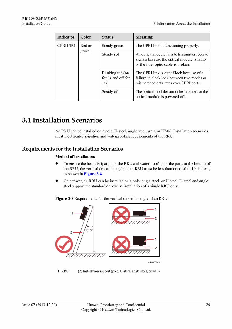
3.4 Installation ScenariosAn RRU can be installed on a pole, U-steel, angle steel, wall, or IFS06. Installation scenariosmust meet heat-dissipation and waterproofing requirements of the RRU.
Requirements for the Installation ScenariosMethod of installation:
l To ensure the heat dissipation of the RRU and waterproofing of the ports at the bottom ofthe RRU, the vertical deviation angle of an RRU must be less than or equal to 10 degrees,as shown in Figure 3-8.
l On a tower, an RRU can be installed on a pole, angle steel, or U-steel. U-steel and anglesteel support the standard or reverse installation of a single RRU only.
Figure 3-8 Requirements for the vertical deviation angle of an RRU
(1) RRU (2) Installation support (pole, U-steel, angle steel, or wall)
RRU3942&RRU3642Installation Guide 3 Information About the Installation
Issue 07 (2013-12-30) Huawei Proprietary and ConfidentialCopyright © Huawei Technologies Co., Ltd.
20
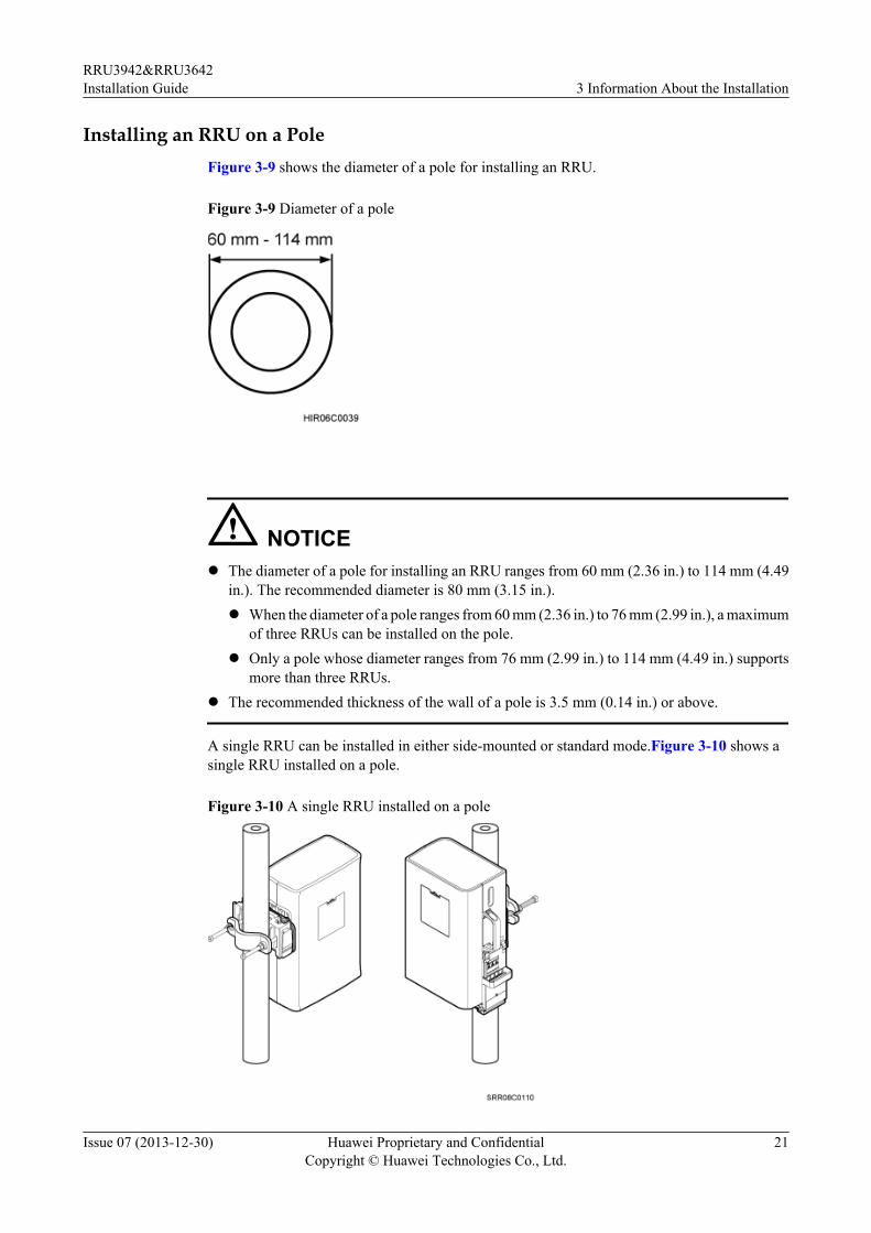
Installing an RRU on a PoleFigure 3-9 shows the diameter of a pole for installing an RRU.
Figure 3-9 Diameter of a pole
NOTICEl The diameter of a pole for installing an RRU ranges from 60 mm (2.36 in.) to 114 mm (4.49
in.). The recommended diameter is 80 mm (3.15 in.).l When the diameter of a pole ranges from 60 mm (2.36 in.) to 76 mm (2.99 in.), a maximum
of three RRUs can be installed on the pole.l Only a pole whose diameter ranges from 76 mm (2.99 in.) to 114 mm (4.49 in.) supports
more than three RRUs.l The recommended thickness of the wall of a pole is 3.5 mm (0.14 in.) or above.
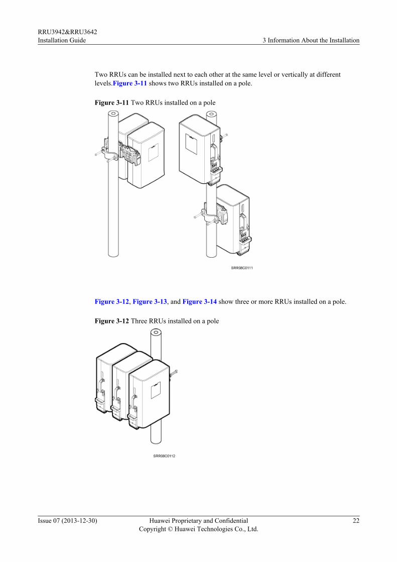
A single RRU can be installed in either side-mounted or standard mode.Figure 3-10 shows asingle RRU installed on a pole.
Figure 3-10 A single RRU installed on a pole
RRU3942&RRU3642Installation Guide 3 Information About the Installation
Issue 07 (2013-12-30) Huawei Proprietary and ConfidentialCopyright © Huawei Technologies Co., Ltd.
21
Two RRUs can be installed next to each other at the same level or vertically at differentlevels.Figure 3-11 shows two RRUs installed on a pole.
Figure 3-11 Two RRUs installed on a pole
Figure 3-12, Figure 3-13, and Figure 3-14 show three or more RRUs installed on a pole.
Figure 3-12 Three RRUs installed on a pole
RRU3942&RRU3642Installation Guide 3 Information About the Installation
Issue 07 (2013-12-30) Huawei Proprietary and ConfidentialCopyright © Huawei Technologies Co., Ltd.
22
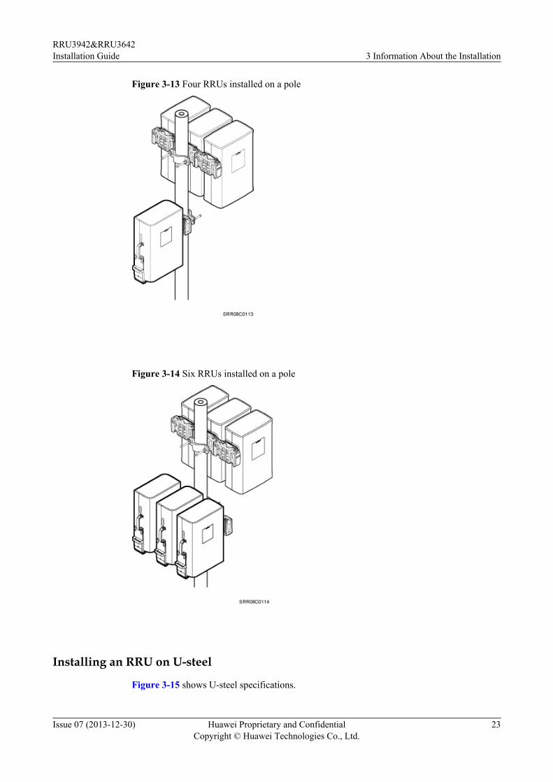
Figure 3-13 Four RRUs installed on a pole
Figure 3-14 Six RRUs installed on a pole
Installing an RRU on U-steel
Figure 3-15 shows U-steel specifications.
RRU3942&RRU3642Installation Guide 3 Information About the Installation
Issue 07 (2013-12-30) Huawei Proprietary and ConfidentialCopyright © Huawei Technologies Co., Ltd.
23
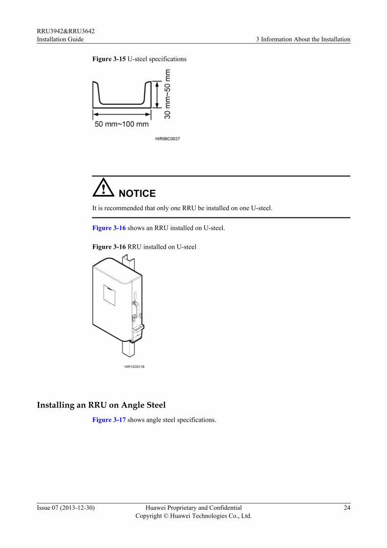
Figure 3-15 U-steel specifications
NOTICEIt is recommended that only one RRU be installed on one U-steel.
Figure 3-16 shows an RRU installed on U-steel.
Figure 3-16 RRU installed on U-steel
Installing an RRU on Angle SteelFigure 3-17 shows angle steel specifications.
RRU3942&RRU3642Installation Guide 3 Information About the Installation
Issue 07 (2013-12-30) Huawei Proprietary and ConfidentialCopyright © Huawei Technologies Co., Ltd.
24
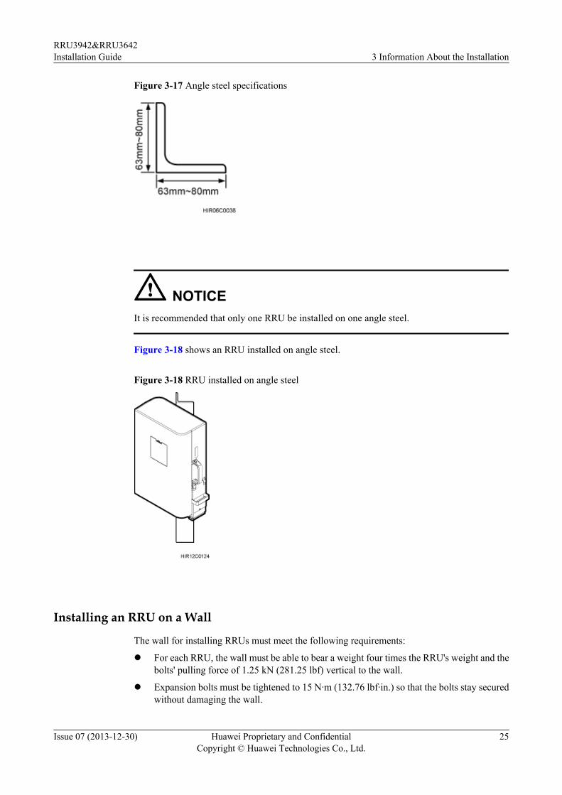
Figure 3-17 Angle steel specifications
NOTICEIt is recommended that only one RRU be installed on one angle steel.
Figure 3-18 shows an RRU installed on angle steel.
Figure 3-18 RRU installed on angle steel
Installing an RRU on a Wall
The wall for installing RRUs must meet the following requirements:
l For each RRU, the wall must be able to bear a weight four times the RRU's weight and thebolts' pulling force of 1.25 kN (281.25 lbf) vertical to the wall.
l Expansion bolts must be tightened to 15 N·m (132.76 lbf·in.) so that the bolts stay securedwithout damaging the wall.
RRU3942&RRU3642Installation Guide 3 Information About the Installation
Issue 07 (2013-12-30) Huawei Proprietary and ConfidentialCopyright © Huawei Technologies Co., Ltd.
25
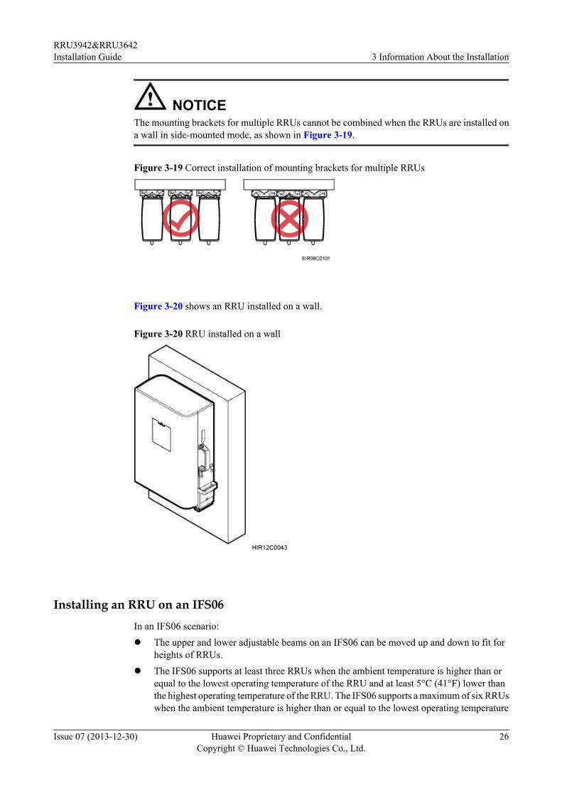
NOTICEThe mounting brackets for multiple RRUs cannot be combined when the RRUs are installed ona wall in side-mounted mode, as shown in Figure 3-19.
Figure 3-19 Correct installation of mounting brackets for multiple RRUs
Figure 3-20 shows an RRU installed on a wall.
Figure 3-20 RRU installed on a wall
Installing an RRU on an IFS06In an IFS06 scenario:l The upper and lower adjustable beams on an IFS06 can be moved up and down to fit for
heights of RRUs.l The IFS06 supports at least three RRUs when the ambient temperature is higher than or
equal to the lowest operating temperature of the RRU and at least 5°C (41°F) lower thanthe highest operating temperature of the RRU. The IFS06 supports a maximum of six RRUswhen the ambient temperature is higher than or equal to the lowest operating temperature
RRU3942&RRU3642Installation Guide 3 Information About the Installation
Issue 07 (2013-12-30) Huawei Proprietary and ConfidentialCopyright © Huawei Technologies Co., Ltd.
26
of the RRU and at least 10°C (50°F) lower than the highest operating temperature of theRRU.
NOTE
For details about the operating temperature of the RRU, see section "Technical Specifications ofRRUs" in 3900 Series Base Station Technical Description.
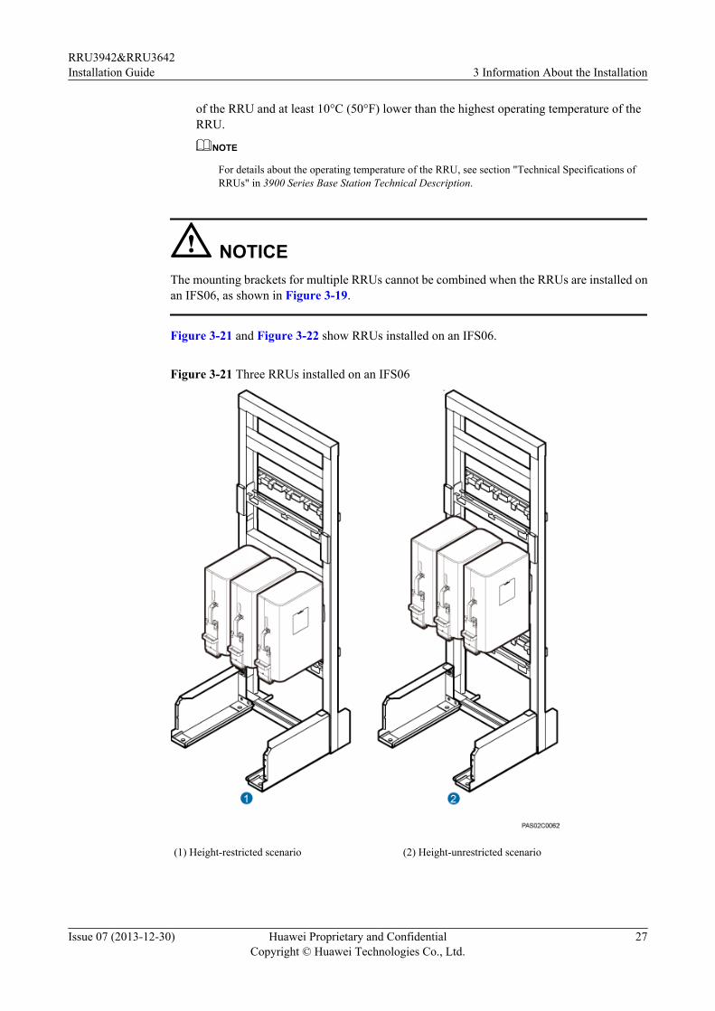
NOTICEThe mounting brackets for multiple RRUs cannot be combined when the RRUs are installed onan IFS06, as shown in Figure 3-19.
Figure 3-21 and Figure 3-22 show RRUs installed on an IFS06.
Figure 3-21 Three RRUs installed on an IFS06
(1) Height-restricted scenario (2) Height-unrestricted scenario
RRU3942&RRU3642Installation Guide 3 Information About the Installation
Issue 07 (2013-12-30) Huawei Proprietary and ConfidentialCopyright © Huawei Technologies Co., Ltd.
27
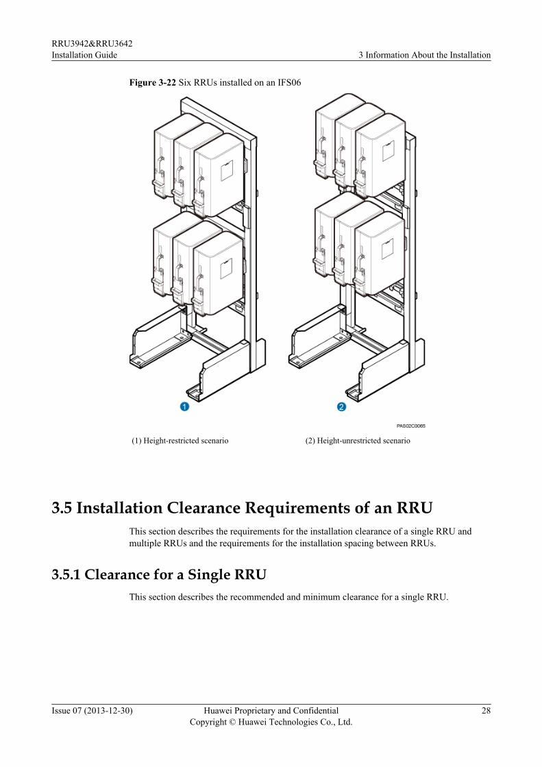
Figure 3-22 Six RRUs installed on an IFS06
(1) Height-restricted scenario (2) Height-unrestricted scenario
3.5 Installation Clearance Requirements of an RRUThis section describes the requirements for the installation clearance of a single RRU andmultiple RRUs and the requirements for the installation spacing between RRUs.
3.5.1 Clearance for a Single RRUThis section describes the recommended and minimum clearance for a single RRU.
RRU3942&RRU3642Installation Guide 3 Information About the Installation
Issue 07 (2013-12-30) Huawei Proprietary and ConfidentialCopyright © Huawei Technologies Co., Ltd.
28
NOTE
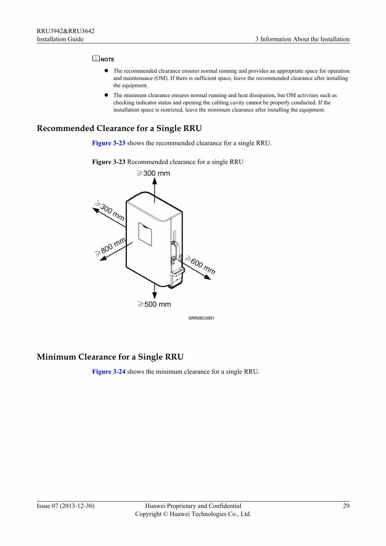
l The recommended clearance ensures normal running and provides an appropriate space for operationand maintenance (OM). If there is sufficient space, leave the recommended clearance after installingthe equipment.
l The minimum clearance ensures normal running and heat dissipation, but OM activities such aschecking indicator status and opening the cabling cavity cannot be properly conducted. If theinstallation space is restricted, leave the minimum clearance after installing the equipment.
Recommended Clearance for a Single RRUFigure 3-23 shows the recommended clearance for a single RRU.
Figure 3-23 Recommended clearance for a single RRU
Minimum Clearance for a Single RRUFigure 3-24 shows the minimum clearance for a single RRU.
RRU3942&RRU3642Installation Guide 3 Information About the Installation
Issue 07 (2013-12-30) Huawei Proprietary and ConfidentialCopyright © Huawei Technologies Co., Ltd.
29
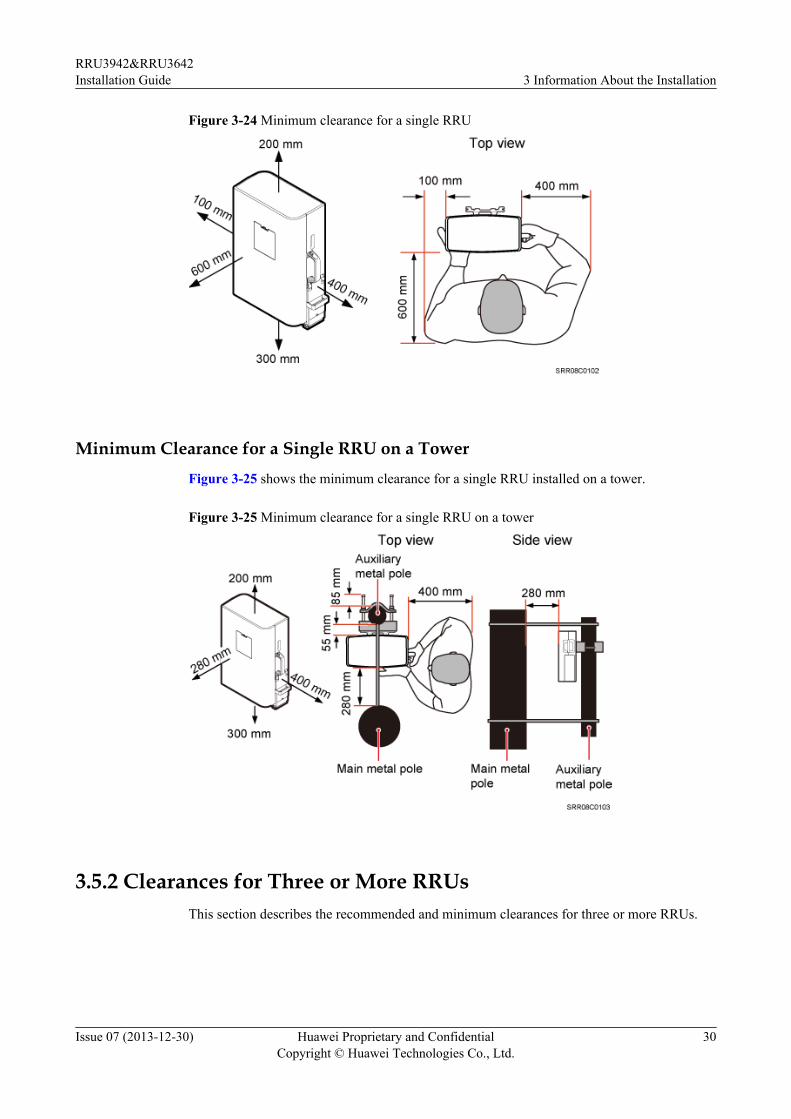
Figure 3-24 Minimum clearance for a single RRU
Minimum Clearance for a Single RRU on a TowerFigure 3-25 shows the minimum clearance for a single RRU installed on a tower.
Figure 3-25 Minimum clearance for a single RRU on a tower
3.5.2 Clearances for Three or More RRUsThis section describes the recommended and minimum clearances for three or more RRUs.
RRU3942&RRU3642Installation Guide 3 Information About the Installation
Issue 07 (2013-12-30) Huawei Proprietary and ConfidentialCopyright © Huawei Technologies Co., Ltd.
30
NOTE
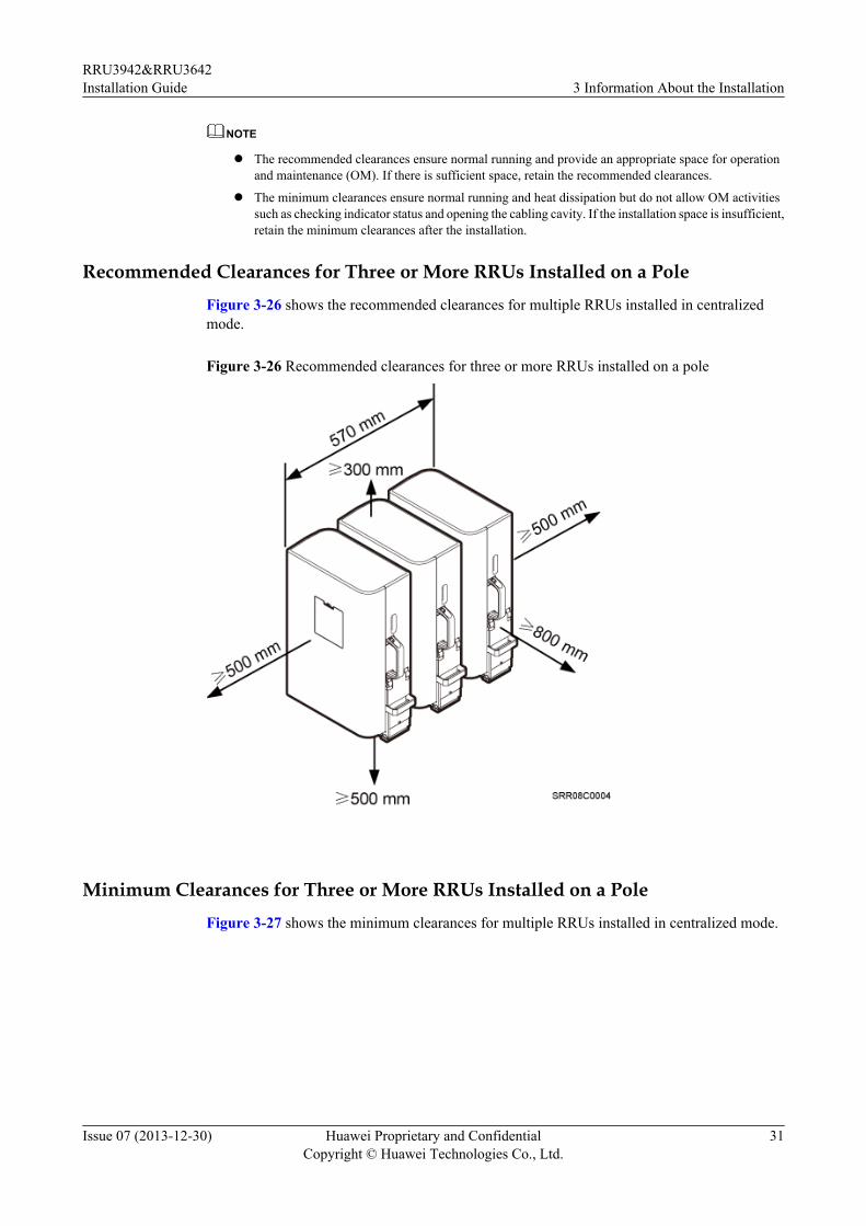
l The recommended clearances ensure normal running and provide an appropriate space for operationand maintenance (OM). If there is sufficient space, retain the recommended clearances.
l The minimum clearances ensure normal running and heat dissipation but do not allow OM activitiessuch as checking indicator status and opening the cabling cavity. If the installation space is insufficient,retain the minimum clearances after the installation.
Recommended Clearances for Three or More RRUs Installed on a PoleFigure 3-26 shows the recommended clearances for multiple RRUs installed in centralizedmode.
Figure 3-26 Recommended clearances for three or more RRUs installed on a pole
Minimum Clearances for Three or More RRUs Installed on a PoleFigure 3-27 shows the minimum clearances for multiple RRUs installed in centralized mode.
RRU3942&RRU3642Installation Guide 3 Information About the Installation
Issue 07 (2013-12-30) Huawei Proprietary and ConfidentialCopyright © Huawei Technologies Co., Ltd.
31
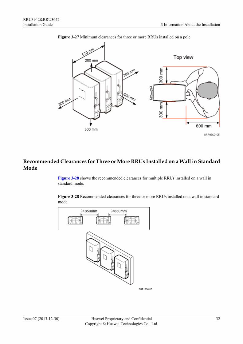
Figure 3-27 Minimum clearances for three or more RRUs installed on a pole
Recommended Clearances for Three or More RRUs Installed on a Wall in StandardMode
Figure 3-28 shows the recommended clearances for multiple RRUs installed on a wall instandard mode.
Figure 3-28 Recommended clearances for three or more RRUs installed on a wall in standardmode
RRU3942&RRU3642Installation Guide 3 Information About the Installation
Issue 07 (2013-12-30) Huawei Proprietary and ConfidentialCopyright © Huawei Technologies Co., Ltd.
32
Minimum Clearances for Three or More RRUs Installed on a Wall in StandardMode
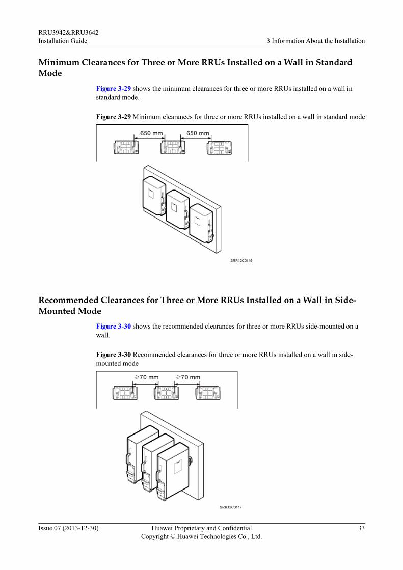
Figure 3-29 shows the minimum clearances for three or more RRUs installed on a wall instandard mode.
Figure 3-29 Minimum clearances for three or more RRUs installed on a wall in standard mode
Recommended Clearances for Three or More RRUs Installed on a Wall in Side-Mounted Mode
Figure 3-30 shows the recommended clearances for three or more RRUs side-mounted on awall.
Figure 3-30 Recommended clearances for three or more RRUs installed on a wall in side-mounted mode
RRU3942&RRU3642Installation Guide 3 Information About the Installation
Issue 07 (2013-12-30) Huawei Proprietary and ConfidentialCopyright © Huawei Technologies Co., Ltd.
33
3.5.3 Installation Spacing Between RRUsThis section describes the horizontal and vertical spacing between RRUs.
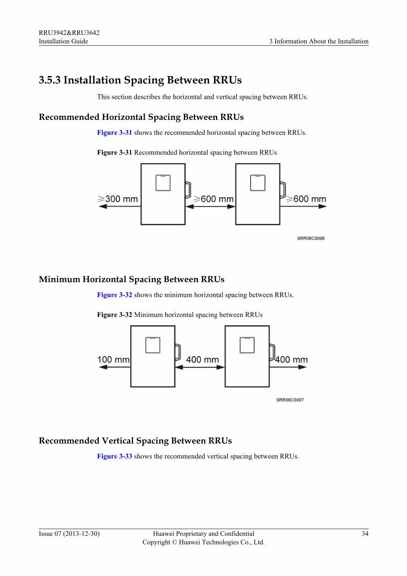
Recommended Horizontal Spacing Between RRUsFigure 3-31 shows the recommended horizontal spacing between RRUs.
Figure 3-31 Recommended horizontal spacing between RRUs
Minimum Horizontal Spacing Between RRUsFigure 3-32 shows the minimum horizontal spacing between RRUs.
Figure 3-32 Minimum horizontal spacing between RRUs
Recommended Vertical Spacing Between RRUsFigure 3-33 shows the recommended vertical spacing between RRUs.
RRU3942&RRU3642Installation Guide 3 Information About the Installation
Issue 07 (2013-12-30) Huawei Proprietary and ConfidentialCopyright © Huawei Technologies Co., Ltd.
34
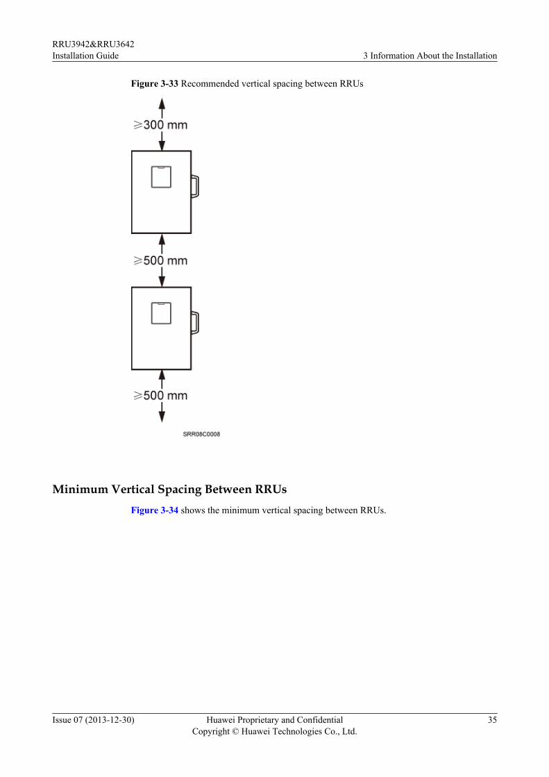
Figure 3-33 Recommended vertical spacing between RRUs
Minimum Vertical Spacing Between RRUsFigure 3-34 shows the minimum vertical spacing between RRUs.
RRU3942&RRU3642Installation Guide 3 Information About the Installation
Issue 07 (2013-12-30) Huawei Proprietary and ConfidentialCopyright © Huawei Technologies Co., Ltd.
35
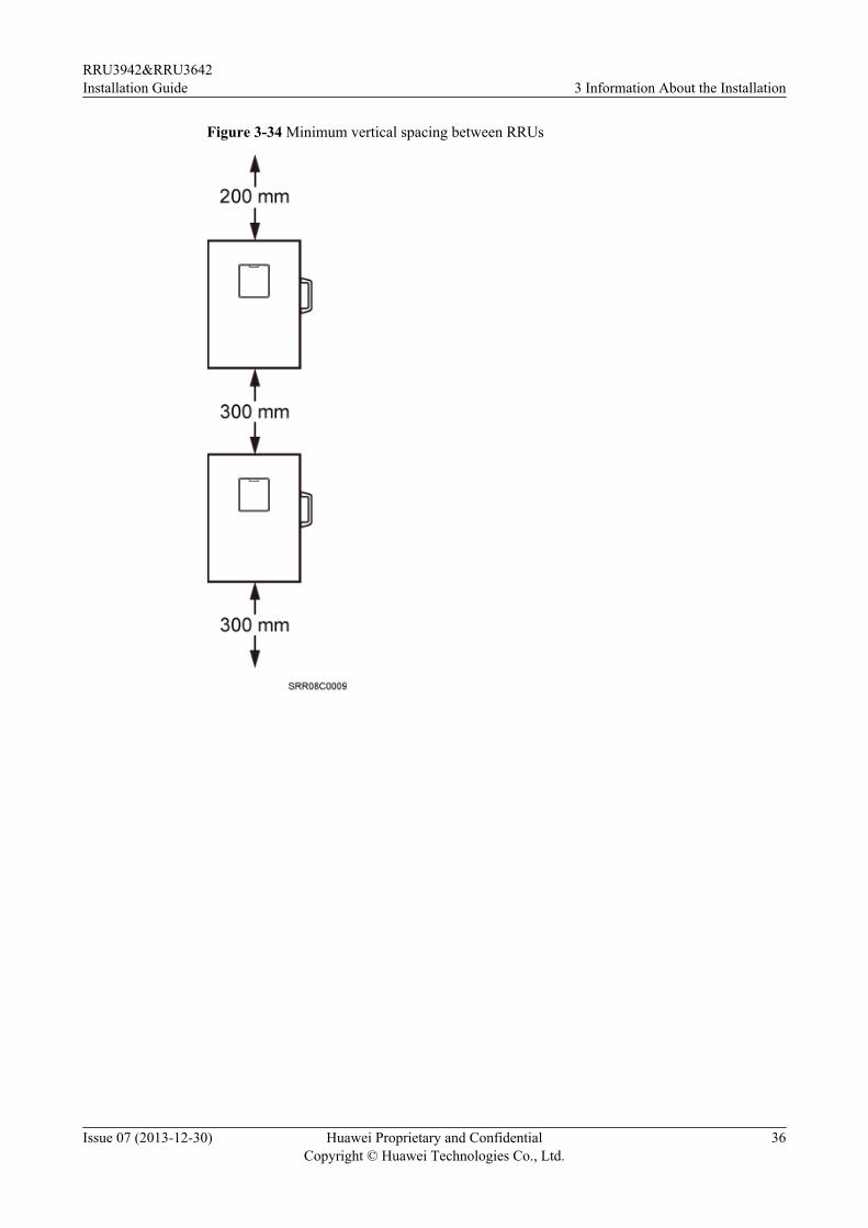
Figure 3-34 Minimum vertical spacing between RRUs
RRU3942&RRU3642Installation Guide 3 Information About the Installation
Issue 07 (2013-12-30) Huawei Proprietary and ConfidentialCopyright © Huawei Technologies Co., Ltd.
36
4 Unpacking the Equipment
This chapter describes how to unpack and check the delivered equipment to ensure that all thematerials are included and intact.
ContextNOTE
When transporting, moving, or installing the equipment, components, or parts, you must:
l Prevent them from colliding with doors, walls, shelves, or other objects.
l Wear clean gloves, and avoid touching the equipment, components, or parts with bare hands, sweat-soaked gloves, or dirty gloves.
NOTICEl After a cabinet or an BBU is unpacked, it must be powered on within 7 days.
l After an RRU is unpacked, it must be powered on within 24 hours.
Procedure
Step 1 Check the total number of articles in each case according to the packing list.
If ... Then ...
The total number tallies with the packinglist
Go to Step 2.
The total number does not tally with thepacking list
Find out the cause and report any missingarticles to the local Huawei office.
Step 2 Check the exterior of the packing case.
RRU3942&RRU3642Installation Guide 4 Unpacking the Equipment
Issue 07 (2013-12-30) Huawei Proprietary and ConfidentialCopyright © Huawei Technologies Co., Ltd.
37
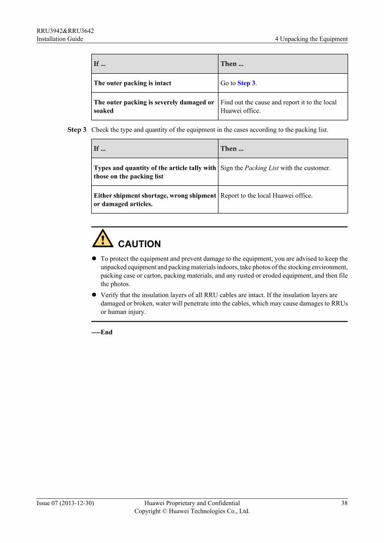
If ... Then ...
The outer packing is intact Go to Step 3.
The outer packing is severely damaged orsoaked
Find out the cause and report it to the localHuawei office.
Step 3 Check the type and quantity of the equipment in the cases according to the packing list.
If ... Then ...
Types and quantity of the article tally withthose on the packing list
Sign the Packing List with the customer.
Either shipment shortage, wrong shipmentor damaged articles.
Report to the local Huawei office.
CAUTIONl To protect the equipment and prevent damage to the equipment, you are advised to keep the
unpacked equipment and packing materials indoors, take photos of the stocking environment,packing case or carton, packing materials, and any rusted or eroded equipment, and then filethe photos.
l Verify that the insulation layers of all RRU cables are intact. If the insulation layers aredamaged or broken, water will penetrate into the cables, which may cause damages to RRUsor human injury.
----End
RRU3942&RRU3642Installation Guide 4 Unpacking the Equipment
Issue 07 (2013-12-30) Huawei Proprietary and ConfidentialCopyright © Huawei Technologies Co., Ltd.
38
5 Installation Process
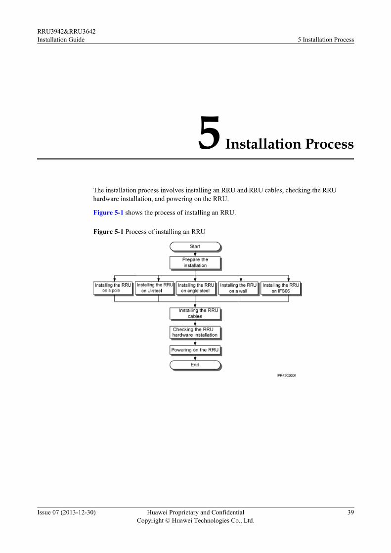
The installation process involves installing an RRU and RRU cables, checking the RRUhardware installation, and powering on the RRU.
Figure 5-1 shows the process of installing an RRU.
Figure 5-1 Process of installing an RRU
RRU3942&RRU3642Installation Guide 5 Installation Process
Issue 07 (2013-12-30) Huawei Proprietary and ConfidentialCopyright © Huawei Technologies Co., Ltd.
39
6 Hoisting an RRU and Related Cables onto aTower
About This Chapter
This section describes the procedure for hoisting an RRU and related cables onto a tower andthe precautions that must be taken.
6.1 Hoisting an RRU onto a TowerThis section describes the procedures and precautions for hoisting an RRU and its mounting kitsonto a tower. In tower-mounted scenarios, the RRU can be installed on a pole, U-steel, or anglesteel.
6.2 Hoisting Fiber Optic Cables onto a TowerThis section describes the procedure for hoisting fiber optic cables onto a tower and theprecautions that must be taken.
6.3 Hoisting Power Cables onto a TowerThis section describes the procedure for hoisting power cables onto a tower and the precautionsthat must be taken.
RRU3942&RRU3642Installation Guide 6 Hoisting an RRU and Related Cables onto a Tower
Issue 07 (2013-12-30) Huawei Proprietary and ConfidentialCopyright © Huawei Technologies Co., Ltd.
40
6.1 Hoisting an RRU onto a TowerThis section describes the procedures and precautions for hoisting an RRU and its mounting kitsonto a tower. In tower-mounted scenarios, the RRU can be installed on a pole, U-steel, or anglesteel.
Prerequisites
When the RRU is powered by an AC/DC power module, you need to install the AC/DC powermodule onto the RRU before hoisting them onto a tower. For detailed operations, see AC/DCPower Module User Guide or OPM15M User Guide.
NOTICEl Do not stand the RRU upright because the RF ports cannot support the weight of the RRU.
l Place a foam pad or cardboard under the RRU to protect the RRU housing from damageduring the installation.
Procedure
Step 1 After climbing up to the tower, technician A secures the fixed pulley to the tower platformsupport and leads the lifting sling through the fixed pulley.
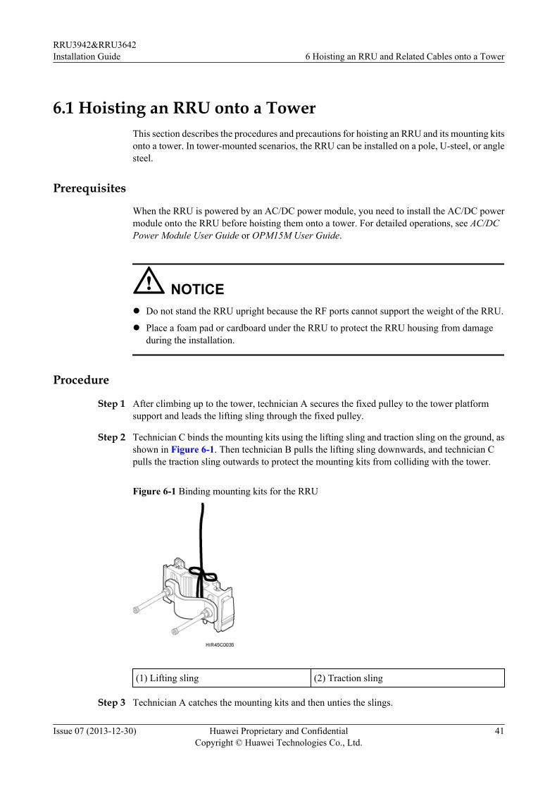
Step 2 Technician C binds the mounting kits using the lifting sling and traction sling on the ground, asshown in Figure 6-1. Then technician B pulls the lifting sling downwards, and technician Cpulls the traction sling outwards to protect the mounting kits from colliding with the tower.
Figure 6-1 Binding mounting kits for the RRU
(1) Lifting sling (2) Traction sling
Step 3 Technician A catches the mounting kits and then unties the slings.
RRU3942&RRU3642Installation Guide 6 Hoisting an RRU and Related Cables onto a Tower
Issue 07 (2013-12-30) Huawei Proprietary and ConfidentialCopyright © Huawei Technologies Co., Ltd.
41
Step 4 Install the mounting kits. For detailed operations, see steps 1 to 3 in 7.2.1 Installing a SingleRRU.
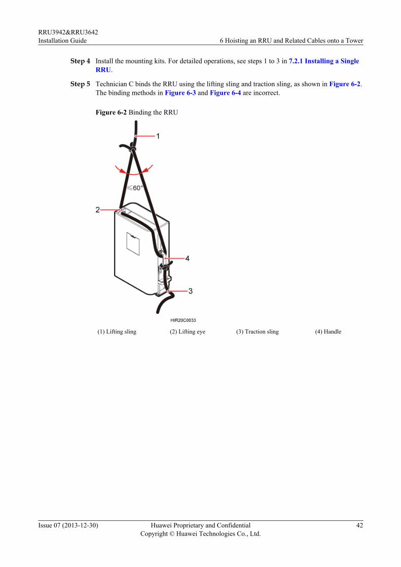
Step 5 Technician C binds the RRU using the lifting sling and traction sling, as shown in Figure 6-2.The binding methods in Figure 6-3 and Figure 6-4 are incorrect.
Figure 6-2 Binding the RRU
(1) Lifting sling (2) Lifting eye (3) Traction sling (4) Handle
RRU3942&RRU3642Installation Guide 6 Hoisting an RRU and Related Cables onto a Tower
Issue 07 (2013-12-30) Huawei Proprietary and ConfidentialCopyright © Huawei Technologies Co., Ltd.
42
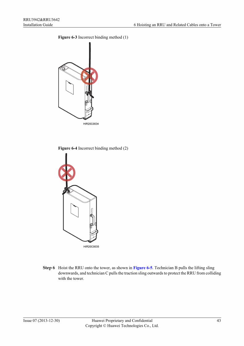
Figure 6-3 Incorrect binding method (1)
Figure 6-4 Incorrect binding method (2)
Step 6 Hoist the RRU onto the tower, as shown in Figure 6-5. Technician B pulls the lifting slingdownwards, and technician C pulls the traction sling outwards to protect the RRU from collidingwith the tower.
RRU3942&RRU3642Installation Guide 6 Hoisting an RRU and Related Cables onto a Tower
Issue 07 (2013-12-30) Huawei Proprietary and ConfidentialCopyright © Huawei Technologies Co., Ltd.
43
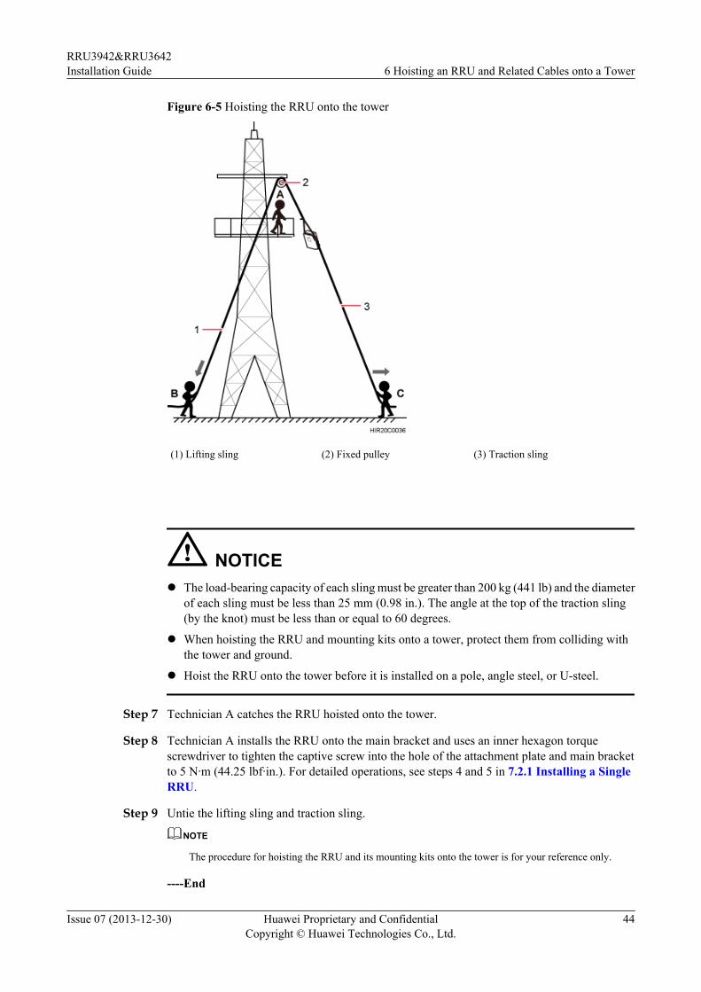
Figure 6-5 Hoisting the RRU onto the tower
(1) Lifting sling (2) Fixed pulley (3) Traction sling
NOTICEl The load-bearing capacity of each sling must be greater than 200 kg (441 lb) and the diameter
of each sling must be less than 25 mm (0.98 in.). The angle at the top of the traction sling(by the knot) must be less than or equal to 60 degrees.
l When hoisting the RRU and mounting kits onto a tower, protect them from colliding withthe tower and ground.
l Hoist the RRU onto the tower before it is installed on a pole, angle steel, or U-steel.
Step 7 Technician A catches the RRU hoisted onto the tower.
Step 8 Technician A installs the RRU onto the main bracket and uses an inner hexagon torquescrewdriver to tighten the captive screw into the hole of the attachment plate and main bracketto 5 N·m (44.25 lbf·in.). For detailed operations, see steps 4 and 5 in 7.2.1 Installing a SingleRRU.
Step 9 Untie the lifting sling and traction sling.
NOTE
The procedure for hoisting the RRU and its mounting kits onto the tower is for your reference only.
----End
RRU3942&RRU3642Installation Guide 6 Hoisting an RRU and Related Cables onto a Tower
Issue 07 (2013-12-30) Huawei Proprietary and ConfidentialCopyright © Huawei Technologies Co., Ltd.
44
6.2 Hoisting Fiber Optic Cables onto a TowerThis section describes the procedure for hoisting fiber optic cables onto a tower and theprecautions that must be taken.
ContextCabling requirements for power cables are met. For details, see 8.1 Cabling Requirements.
Procedure
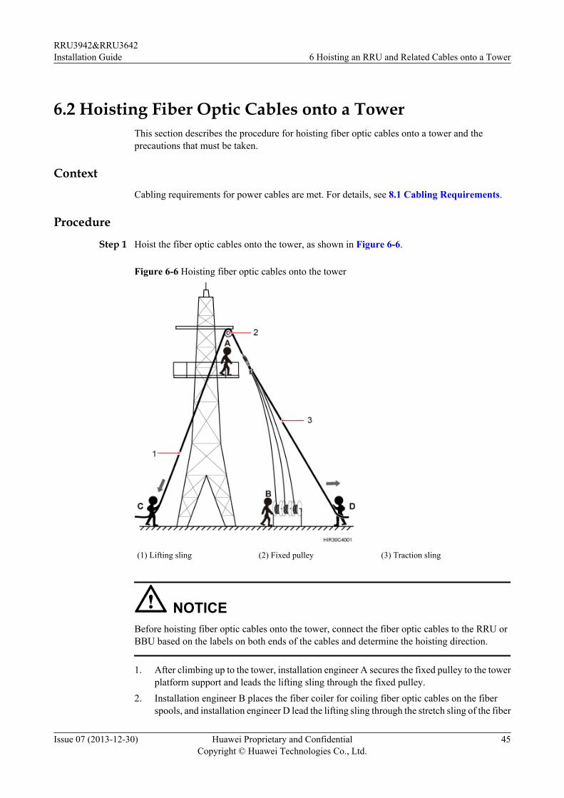
Step 1 Hoist the fiber optic cables onto the tower, as shown in Figure 6-6.
Figure 6-6 Hoisting fiber optic cables onto the tower
(1) Lifting sling (2) Fixed pulley (3) Traction sling
NOTICEBefore hoisting fiber optic cables onto the tower, connect the fiber optic cables to the RRU orBBU based on the labels on both ends of the cables and determine the hoisting direction.
1. After climbing up to the tower, installation engineer A secures the fixed pulley to the towerplatform support and leads the lifting sling through the fixed pulley.
2. Installation engineer B places the fiber coiler for coiling fiber optic cables on the fiberspools, and installation engineer D lead the lifting sling through the stretch sling of the fiber
RRU3942&RRU3642Installation Guide 6 Hoisting an RRU and Related Cables onto a Tower
Issue 07 (2013-12-30) Huawei Proprietary and ConfidentialCopyright © Huawei Technologies Co., Ltd.
45
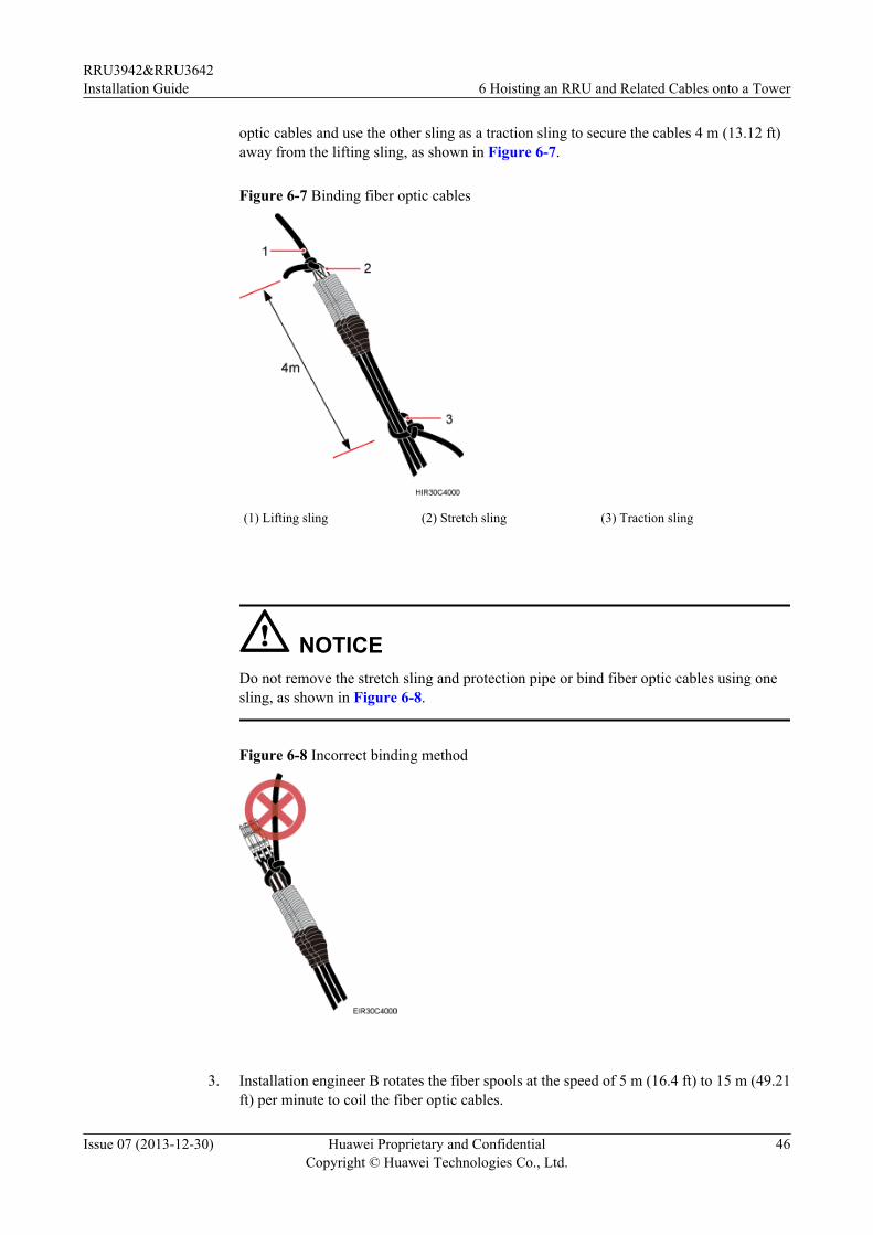
optic cables and use the other sling as a traction sling to secure the cables 4 m (13.12 ft)away from the lifting sling, as shown in Figure 6-7.
Figure 6-7 Binding fiber optic cables
(1) Lifting sling (2) Stretch sling (3) Traction sling
NOTICEDo not remove the stretch sling and protection pipe or bind fiber optic cables using onesling, as shown in Figure 6-8.
Figure 6-8 Incorrect binding method
3. Installation engineer B rotates the fiber spools at the speed of 5 m (16.4 ft) to 15 m (49.21ft) per minute to coil the fiber optic cables.
RRU3942&RRU3642Installation Guide 6 Hoisting an RRU and Related Cables onto a Tower
Issue 07 (2013-12-30) Huawei Proprietary and ConfidentialCopyright © Huawei Technologies Co., Ltd.
46
4. Installation engineer C pulls the lifting sling downwards, and installation engineer D pullsthe traction sling outwards to protect the fiber optic cables from colliding with the tower.
Step 2 Secure the fiber optic cables to the tower vertically using cable clips.
Step 3 Remove the lifting sling, traction sling, and protection pipe.
NOTE
The procedure for hoisting the fiber optic cables onto the tower is for your reference only.
----End
6.3 Hoisting Power Cables onto a TowerThis section describes the procedure for hoisting power cables onto a tower and the precautionsthat must be taken.
ContextCabling requirements for power cables are met. For details, see 8.1 Cabling Requirements.
The procedure for adding a connector to the RRU power cable on the RRU side is done underthe tower.
Procedure
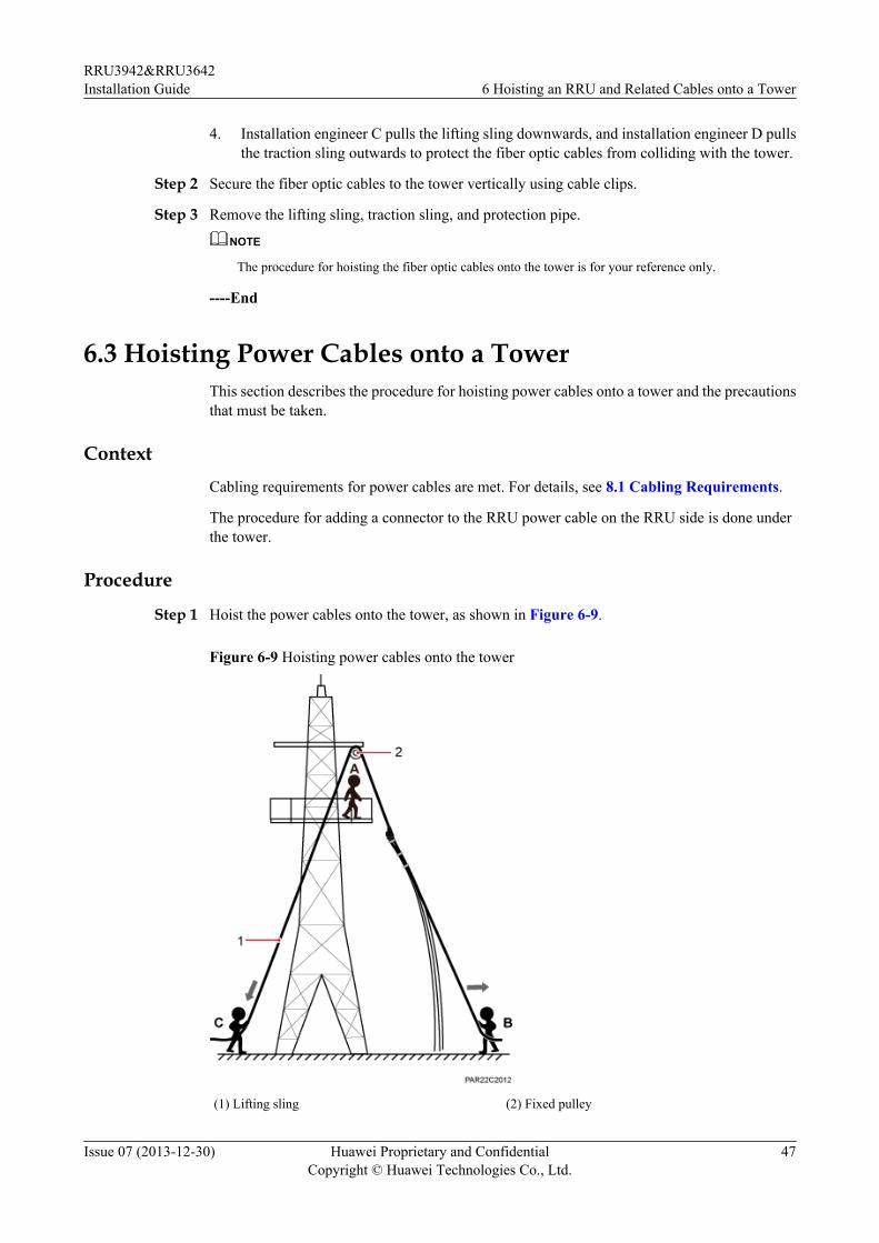
Step 1 Hoist the power cables onto the tower, as shown in Figure 6-9.
Figure 6-9 Hoisting power cables onto the tower
(1) Lifting sling (2) Fixed pulley
RRU3942&RRU3642Installation Guide 6 Hoisting an RRU and Related Cables onto a Tower
Issue 07 (2013-12-30) Huawei Proprietary and ConfidentialCopyright © Huawei Technologies Co., Ltd.
47
1. After climbing up to the tower, installation engineer A secures the fixed pulley to the tower
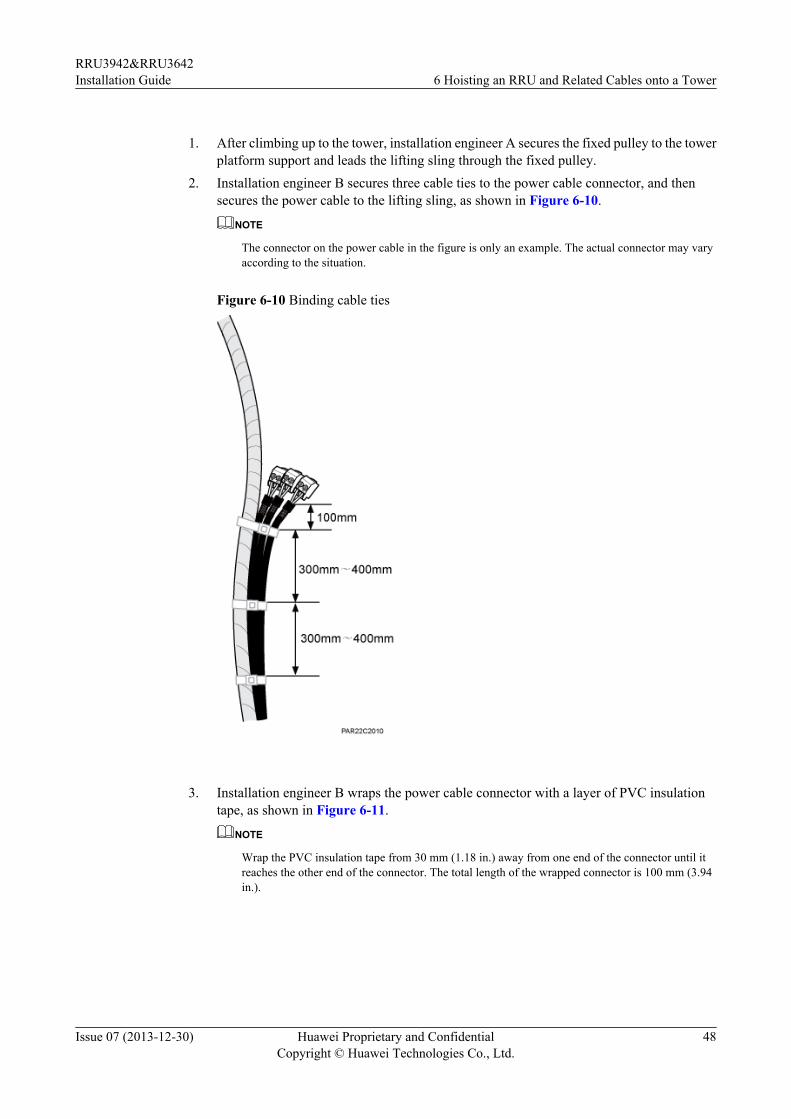
platform support and leads the lifting sling through the fixed pulley.2. Installation engineer B secures three cable ties to the power cable connector, and then
secures the power cable to the lifting sling, as shown in Figure 6-10.
NOTE
The connector on the power cable in the figure is only an example. The actual connector may varyaccording to the situation.
Figure 6-10 Binding cable ties
3. Installation engineer B wraps the power cable connector with a layer of PVC insulation
tape, as shown in Figure 6-11.
NOTE
Wrap the PVC insulation tape from 30 mm (1.18 in.) away from one end of the connector until itreaches the other end of the connector. The total length of the wrapped connector is 100 mm (3.94in.).
RRU3942&RRU3642Installation Guide 6 Hoisting an RRU and Related Cables onto a Tower
Issue 07 (2013-12-30) Huawei Proprietary and ConfidentialCopyright © Huawei Technologies Co., Ltd.
48
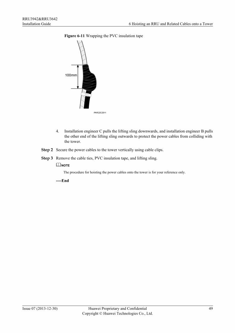
Figure 6-11 Wrapping the PVC insulation tape
4. Installation engineer C pulls the lifting sling downwards, and installation engineer B pulls
the other end of the lifting sling outwards to protect the power cables from colliding withthe tower.
Step 2 Secure the power cables to the tower vertically using cable clips.
Step 3 Remove the cable ties, PVC insulation tape, and lifting sling.
NOTE
The procedure for hoisting the power cables onto the tower is for your reference only.
----End
RRU3942&RRU3642Installation Guide 6 Hoisting an RRU and Related Cables onto a Tower
Issue 07 (2013-12-30) Huawei Proprietary and ConfidentialCopyright © Huawei Technologies Co., Ltd.
49
7 Installing the RRU
About This Chapter
This chapter describes the procedure for installing the RRU. The procedure for installing theRRU varies depending on installation options.
7.1 Mounting Kits for an RRUThis section describes the bracket assembly and the attachment plate for an RRU.
7.2 Installing the RRU on a PoleOne or more RRUs can be installed on a pole.
7.3 Installing the RRU on U-steelThis section describes the procedure and precautions for installing the RRU on U-steel. U-steelcan be installed either on the ground or a tower and only one RRU can be installed on a pieceof U-steel. An RRU on U-steel is installed in standard mode by default.
7.4 Installing the RRU on Angle SteelThis section describes the procedure and precautions for installing the RRU on angle steel. Anglesteel can be installed either on the ground or a tower and only one RRU can be installed on apiece of angle steel. An RRU on angle steel is installed in standard mode by default.
7.5 Installing the RRU on a WallThis section describes the procedure and precautions for installing the RRU on a wall. An RRUon a wall is installed in standard mode by default.
7.6 Installing an RRU on an IFS06This section describes the procedure and precautions for installing an RRU on an IFS06.
RRU3942&RRU3642Installation Guide 7 Installing the RRU
Issue 07 (2013-12-30) Huawei Proprietary and ConfidentialCopyright © Huawei Technologies Co., Ltd.
50
7.1 Mounting Kits for an RRUThis section describes the bracket assembly and the attachment plate for an RRU.
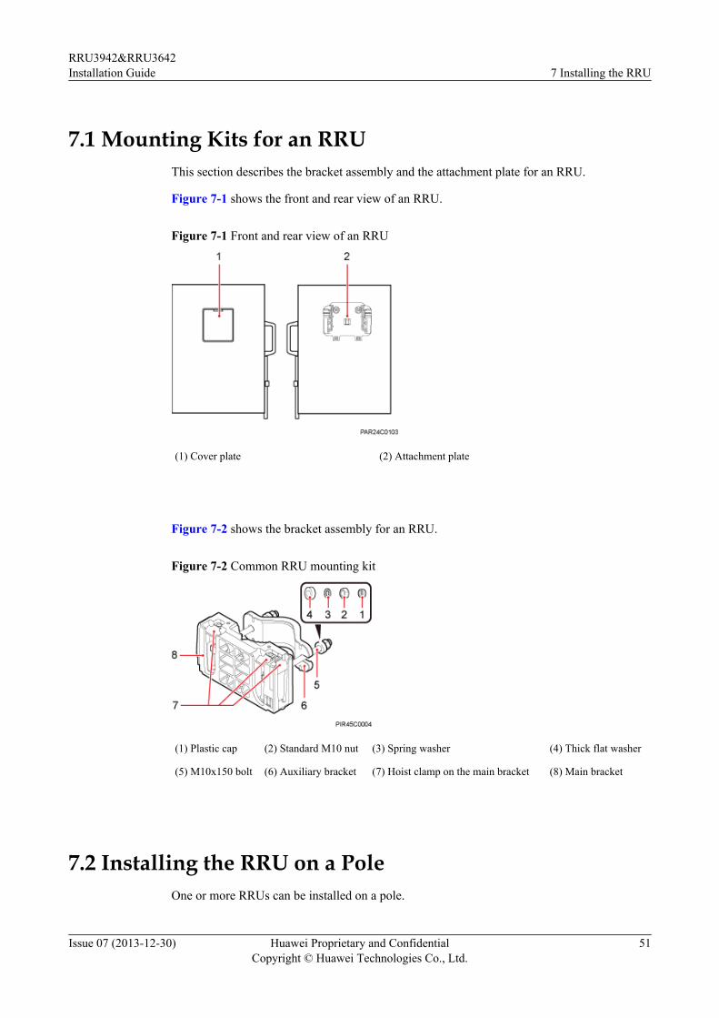
Figure 7-1 shows the front and rear view of an RRU.
Figure 7-1 Front and rear view of an RRU
(1) Cover plate (2) Attachment plate
Figure 7-2 shows the bracket assembly for an RRU.
Figure 7-2 Common RRU mounting kit
(1) Plastic cap (2) Standard M10 nut (3) Spring washer (4) Thick flat washer
(5) M10x150 bolt (6) Auxiliary bracket (7) Hoist clamp on the main bracket (8) Main bracket
7.2 Installing the RRU on a PoleOne or more RRUs can be installed on a pole.
RRU3942&RRU3642Installation Guide 7 Installing the RRU
Issue 07 (2013-12-30) Huawei Proprietary and ConfidentialCopyright © Huawei Technologies Co., Ltd.
51
7.2.1 Installing a Single RRUThis section describes the procedure and precautions for installing a single RRU on a pole. Asingle RRU can be installed on a pole in standard or side-mounted mode.
Prerequisites
Before you install an RRU on a tower, the RRU and mounting brackets are hoisted onto thetower. For details, see 6.1 Hoisting an RRU onto a Tower.
The hoist clamp on the main bracket is secured properly.
NOTICEl Do not stand the RRU upright because the RF ports cannot support the weight of the RRU.
l Place a foam pad or cardboard under the RRU to protect the RRU housing from damageduring the installation.
Procedure
Step 1 Determine a position for installing the mounting bracket.
l If the RRU must be installed on a pole secured on a tower, see 3.5.1 Clearance for a SingleRRU to determine a position.
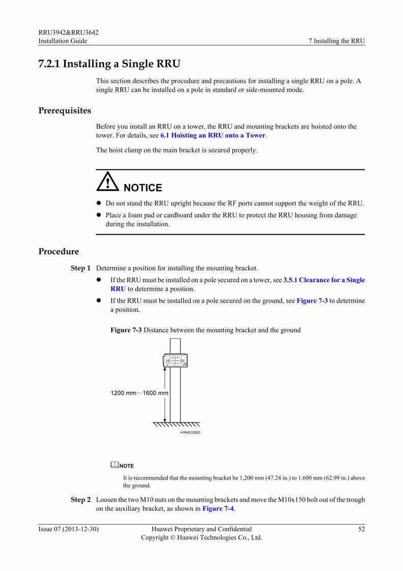
l If the RRU must be installed on a pole secured on the ground, see Figure 7-3 to determinea position.
Figure 7-3 Distance between the mounting bracket and the ground
NOTE
It is recommended that the mounting bracket be 1,200 mm (47.24 in.) to 1,600 mm (62.99 in.) abovethe ground.
Step 2 Loosen the two M10 nuts on the mounting brackets and move the M10x150 bolt out of the troughon the auxiliary bracket, as shown in Figure 7-4.
RRU3942&RRU3642Installation Guide 7 Installing the RRU
Issue 07 (2013-12-30) Huawei Proprietary and ConfidentialCopyright © Huawei Technologies Co., Ltd.
52
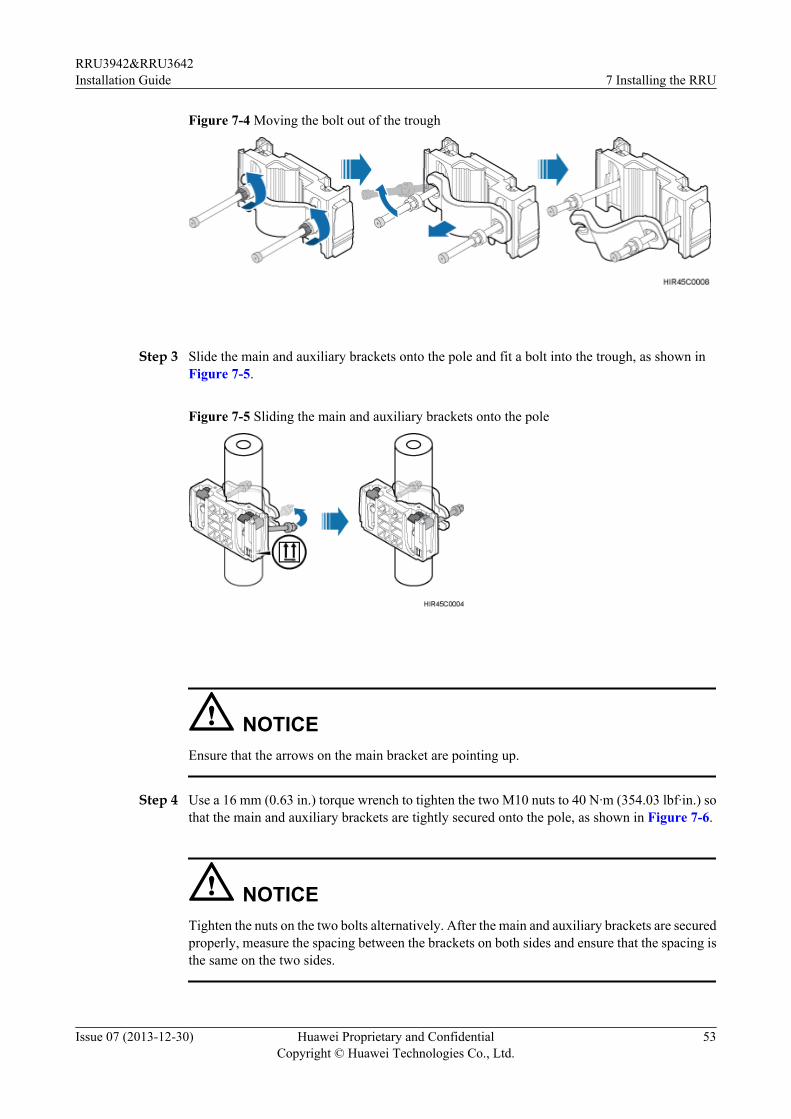
Figure 7-4 Moving the bolt out of the trough
Step 3 Slide the main and auxiliary brackets onto the pole and fit a bolt into the trough, as shown inFigure 7-5.
Figure 7-5 Sliding the main and auxiliary brackets onto the pole
NOTICEEnsure that the arrows on the main bracket are pointing up.
Step 4 Use a 16 mm (0.63 in.) torque wrench to tighten the two M10 nuts to 40 N·m (354.03 lbf·in.) sothat the main and auxiliary brackets are tightly secured onto the pole, as shown in Figure 7-6.
NOTICETighten the nuts on the two bolts alternatively. After the main and auxiliary brackets are securedproperly, measure the spacing between the brackets on both sides and ensure that the spacing isthe same on the two sides.
RRU3942&RRU3642Installation Guide 7 Installing the RRU
Issue 07 (2013-12-30) Huawei Proprietary and ConfidentialCopyright © Huawei Technologies Co., Ltd.
53
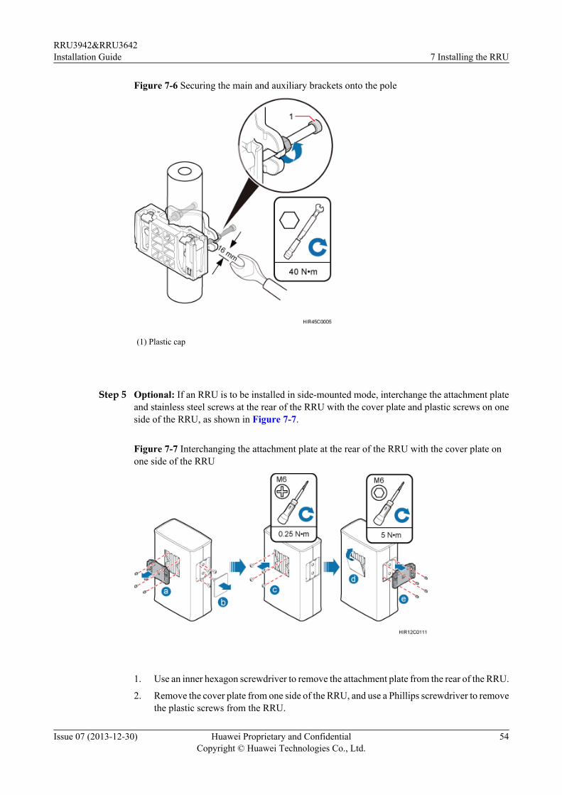
Figure 7-6 Securing the main and auxiliary brackets onto the pole
(1) Plastic cap
Step 5 Optional: If an RRU is to be installed in side-mounted mode, interchange the attachment plateand stainless steel screws at the rear of the RRU with the cover plate and plastic screws on oneside of the RRU, as shown in Figure 7-7.
Figure 7-7 Interchanging the attachment plate at the rear of the RRU with the cover plate onone side of the RRU
1. Use an inner hexagon screwdriver to remove the attachment plate from the rear of the RRU.
2. Remove the cover plate from one side of the RRU, and use a Phillips screwdriver to removethe plastic screws from the RRU.
RRU3942&RRU3642Installation Guide 7 Installing the RRU
Issue 07 (2013-12-30) Huawei Proprietary and ConfidentialCopyright © Huawei Technologies Co., Ltd.
54
3. Install the plastic screws onto the rear of the RRU, and use a torque screwdriver to tightenthe screws to 0.25 N·m (2.21 lbf·in.).
4. Install the cover plate onto the rear of the RRU.5. Install the attachment plate onto the side of the RRU, and use a torque screwdriver to tighten
the stainless steel screws on the attachment plate to 5 N·m (44.25 lbf·in.).
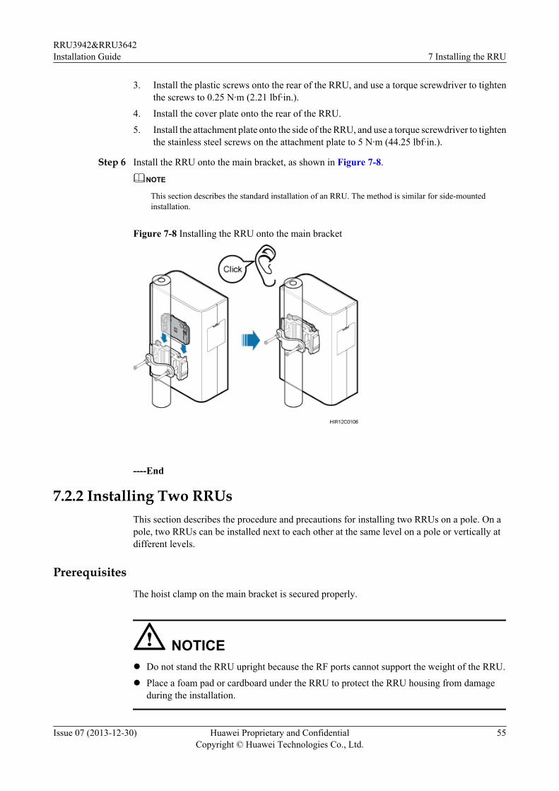
Step 6 Install the RRU onto the main bracket, as shown in Figure 7-8.
NOTE
This section describes the standard installation of an RRU. The method is similar for side-mountedinstallation.
Figure 7-8 Installing the RRU onto the main bracket
----End
7.2.2 Installing Two RRUsThis section describes the procedure and precautions for installing two RRUs on a pole. On apole, two RRUs can be installed next to each other at the same level on a pole or vertically atdifferent levels.
Prerequisites
The hoist clamp on the main bracket is secured properly.
NOTICEl Do not stand the RRU upright because the RF ports cannot support the weight of the RRU.
l Place a foam pad or cardboard under the RRU to protect the RRU housing from damageduring the installation.
RRU3942&RRU3642Installation Guide 7 Installing the RRU
Issue 07 (2013-12-30) Huawei Proprietary and ConfidentialCopyright © Huawei Technologies Co., Ltd.
55
Procedurel Installing two RRUs next to each other at the same level (recommended)
1. Install one pair of main and auxiliary brackets on a pole. For details, see 7.2.1Installing a Single RRU.
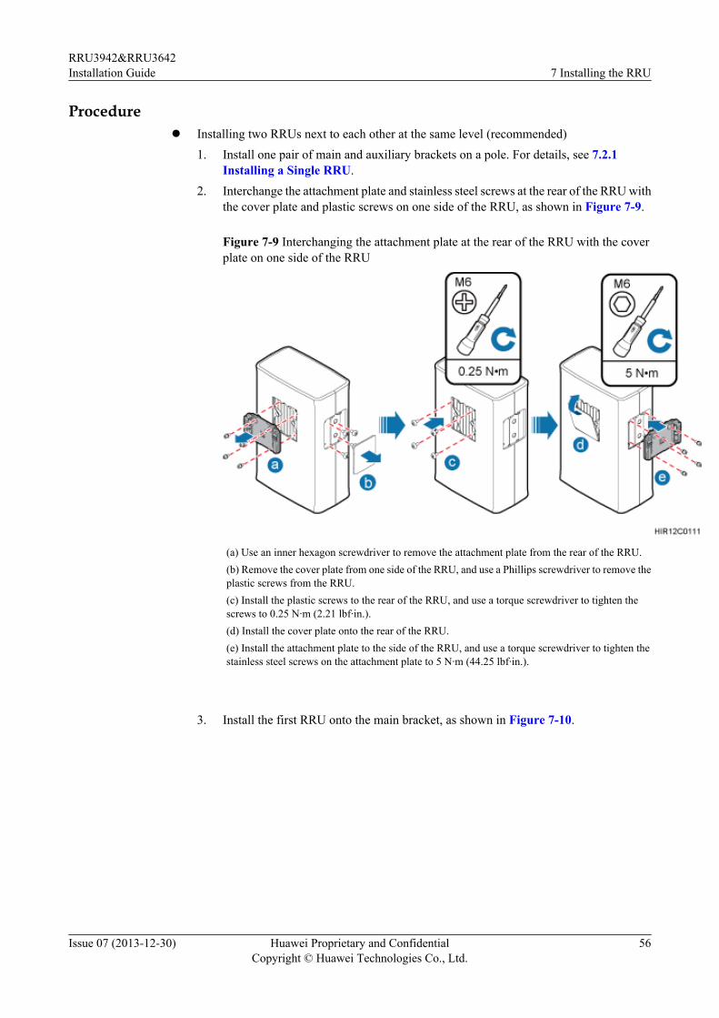
2. Interchange the attachment plate and stainless steel screws at the rear of the RRU withthe cover plate and plastic screws on one side of the RRU, as shown in Figure 7-9.
Figure 7-9 Interchanging the attachment plate at the rear of the RRU with the coverplate on one side of the RRU
(a) Use an inner hexagon screwdriver to remove the attachment plate from the rear of the RRU.(b) Remove the cover plate from one side of the RRU, and use a Phillips screwdriver to remove theplastic screws from the RRU.(c) Install the plastic screws to the rear of the RRU, and use a torque screwdriver to tighten thescrews to 0.25 N·m (2.21 lbf·in.).(d) Install the cover plate onto the rear of the RRU.(e) Install the attachment plate to the side of the RRU, and use a torque screwdriver to tighten thestainless steel screws on the attachment plate to 5 N·m (44.25 lbf·in.).
3. Install the first RRU onto the main bracket, as shown in Figure 7-10.
RRU3942&RRU3642Installation Guide 7 Installing the RRU
Issue 07 (2013-12-30) Huawei Proprietary and ConfidentialCopyright © Huawei Technologies Co., Ltd.
56
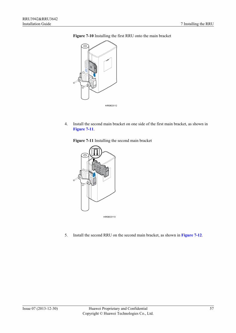
Figure 7-10 Installing the first RRU onto the main bracket
4. Install the second main bracket on one side of the first main bracket, as shown in
Figure 7-11.
Figure 7-11 Installing the second main bracket
5. Install the second RRU on the second main bracket, as shown in Figure 7-12.
RRU3942&RRU3642Installation Guide 7 Installing the RRU
Issue 07 (2013-12-30) Huawei Proprietary and ConfidentialCopyright © Huawei Technologies Co., Ltd.
57
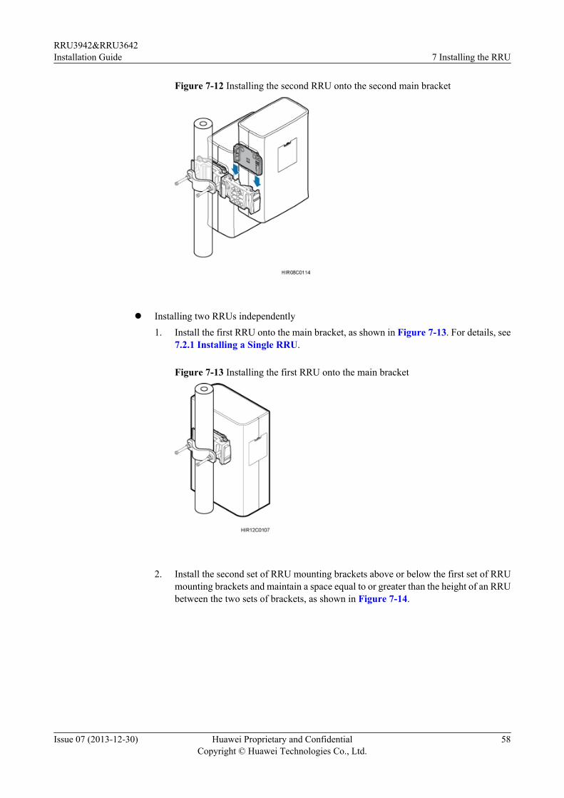
Figure 7-12 Installing the second RRU onto the second main bracket
l Installing two RRUs independently
1. Install the first RRU onto the main bracket, as shown in Figure 7-13. For details, see7.2.1 Installing a Single RRU.
Figure 7-13 Installing the first RRU onto the main bracket
2. Install the second set of RRU mounting brackets above or below the first set of RRU
mounting brackets and maintain a space equal to or greater than the height of an RRUbetween the two sets of brackets, as shown in Figure 7-14.
RRU3942&RRU3642Installation Guide 7 Installing the RRU
Issue 07 (2013-12-30) Huawei Proprietary and ConfidentialCopyright © Huawei Technologies Co., Ltd.
58
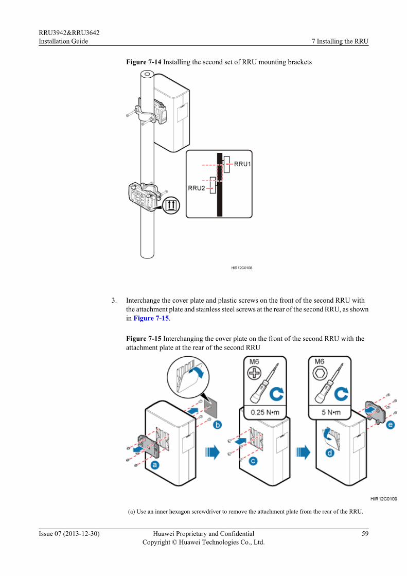
Figure 7-14 Installing the second set of RRU mounting brackets
3. Interchange the cover plate and plastic screws on the front of the second RRU withthe attachment plate and stainless steel screws at the rear of the second RRU, as shownin Figure 7-15.
Figure 7-15 Interchanging the cover plate on the front of the second RRU with theattachment plate at the rear of the second RRU
(a) Use an inner hexagon screwdriver to remove the attachment plate from the rear of the RRU.
RRU3942&RRU3642Installation Guide 7 Installing the RRU
Issue 07 (2013-12-30) Huawei Proprietary and ConfidentialCopyright © Huawei Technologies Co., Ltd.
59
(b) Remove the cover plate from the front of the RRU, and use a Phillips screwdriver to removethe plastic screws from the RRU.(c) Install the plastic screws to the rear of the RRU, and use a torque screwdriver to tighten thescrews to 0.25 N·m (2.21 lbf·in.).(d) Install the cover plate onto the rear of the RRU.(e) Install the attachment plate to the front of the RRU, and use a torque screwdriver to tighten thestainless steel screws on the attachment plate to 5 N·m (44.25 lbf·in.).
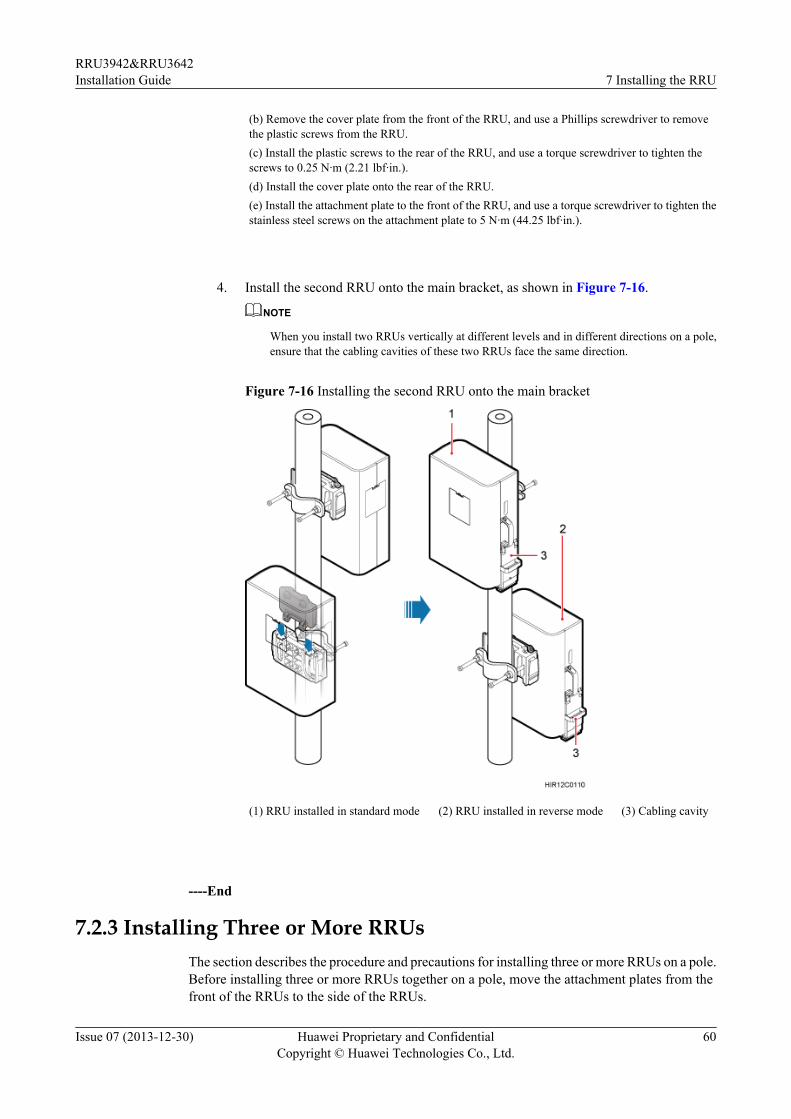
4. Install the second RRU onto the main bracket, as shown in Figure 7-16.
NOTE
When you install two RRUs vertically at different levels and in different directions on a pole,ensure that the cabling cavities of these two RRUs face the same direction.
Figure 7-16 Installing the second RRU onto the main bracket
(1) RRU installed in standard mode (2) RRU installed in reverse mode (3) Cabling cavity
----End
7.2.3 Installing Three or More RRUsThe section describes the procedure and precautions for installing three or more RRUs on a pole.Before installing three or more RRUs together on a pole, move the attachment plates from thefront of the RRUs to the side of the RRUs.
RRU3942&RRU3642Installation Guide 7 Installing the RRU
Issue 07 (2013-12-30) Huawei Proprietary and ConfidentialCopyright © Huawei Technologies Co., Ltd.
60
PrerequisitesThe hoist clamp on the main bracket is secured properly.
NOTICEl Do not stand the RRU upright because the RF ports cannot support the weight of the RRU.l Place a foam pad or cardboard under the RRU to protect the RRU housing from damage
during the installation.
Contextl A pole supports the installation of three, four, or six RRUs. The procedures for installing
them are the same. Following is the procedure of installing four RRUs on a pole.
Procedure
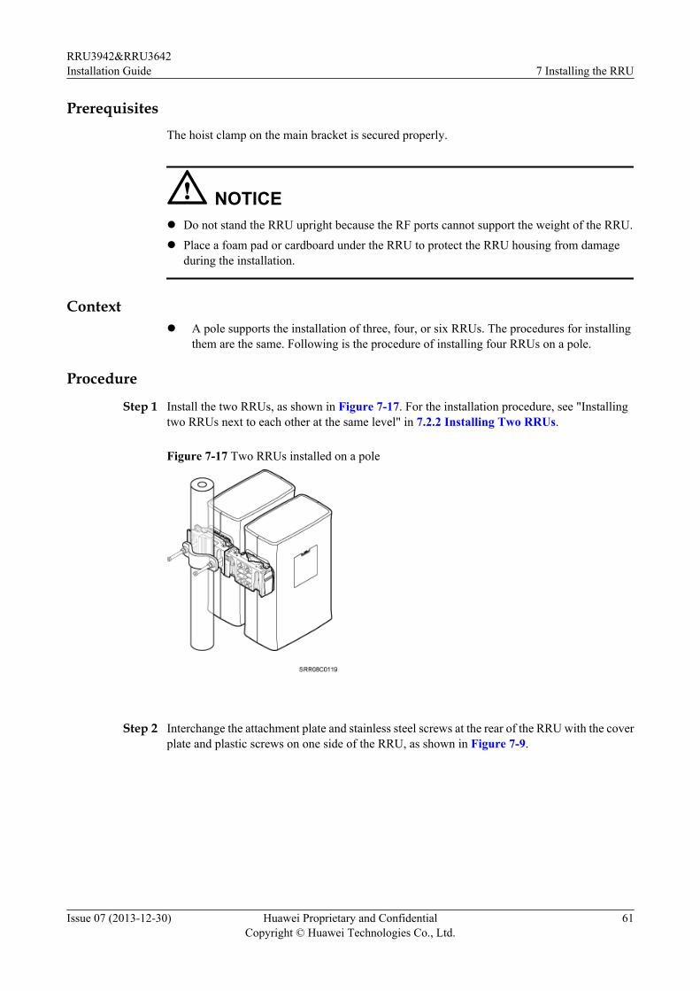
Step 1 Install the two RRUs, as shown in Figure 7-17. For the installation procedure, see "Installingtwo RRUs next to each other at the same level" in 7.2.2 Installing Two RRUs.
Figure 7-17 Two RRUs installed on a pole
Step 2 Interchange the attachment plate and stainless steel screws at the rear of the RRU with the coverplate and plastic screws on one side of the RRU, as shown in Figure 7-9.
RRU3942&RRU3642Installation Guide 7 Installing the RRU
Issue 07 (2013-12-30) Huawei Proprietary and ConfidentialCopyright © Huawei Technologies Co., Ltd.
61
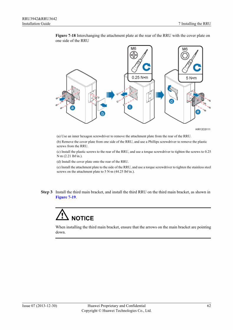
Figure 7-18 Interchanging the attachment plate at the rear of the RRU with the cover plate onone side of the RRU
(a) Use an inner hexagon screwdriver to remove the attachment plate from the rear of the RRU.(b) Remove the cover plate from one side of the RRU, and use a Phillips screwdriver to remove the plasticscrews from the RRU.(c) Install the plastic screws to the rear of the RRU, and use a torque screwdriver to tighten the screws to 0.25N·m (2.21 lbf·in.).(d) Install the cover plate onto the rear of the RRU.(e) Install the attachment plate to the side of the RRU, and use a torque screwdriver to tighten the stainless steelscrews on the attachment plate to 5 N·m (44.25 lbf·in.).
Step 3 Install the third main bracket, and install the third RRU on the third main bracket, as shown inFigure 7-19.
NOTICEWhen installing the third main bracket, ensure that the arrows on the main bracket are pointingdown.
RRU3942&RRU3642Installation Guide 7 Installing the RRU
Issue 07 (2013-12-30) Huawei Proprietary and ConfidentialCopyright © Huawei Technologies Co., Ltd.
62
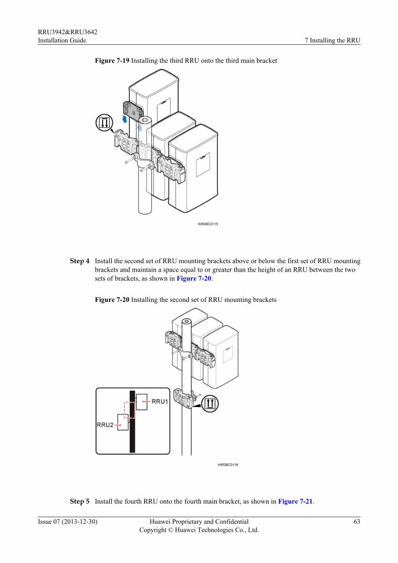
Figure 7-19 Installing the third RRU onto the third main bracket
Step 4 Install the second set of RRU mounting brackets above or below the first set of RRU mountingbrackets and maintain a space equal to or greater than the height of an RRU between the twosets of brackets, as shown in Figure 7-20.
Figure 7-20 Installing the second set of RRU mounting brackets
Step 5 Install the fourth RRU onto the fourth main bracket, as shown in Figure 7-21.
RRU3942&RRU3642Installation Guide 7 Installing the RRU
Issue 07 (2013-12-30) Huawei Proprietary and ConfidentialCopyright © Huawei Technologies Co., Ltd.
63
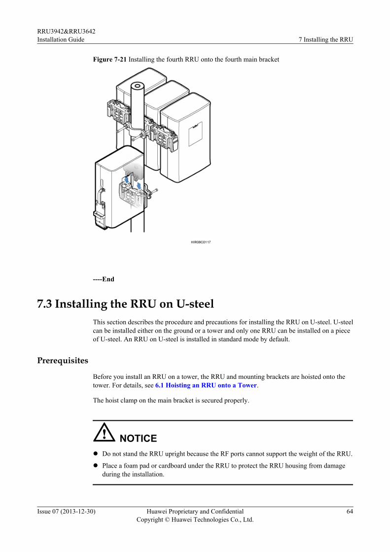
Figure 7-21 Installing the fourth RRU onto the fourth main bracket
----End
7.3 Installing the RRU on U-steelThis section describes the procedure and precautions for installing the RRU on U-steel. U-steelcan be installed either on the ground or a tower and only one RRU can be installed on a pieceof U-steel. An RRU on U-steel is installed in standard mode by default.
Prerequisites
Before you install an RRU on a tower, the RRU and mounting brackets are hoisted onto thetower. For details, see 6.1 Hoisting an RRU onto a Tower.
The hoist clamp on the main bracket is secured properly.
NOTICEl Do not stand the RRU upright because the RF ports cannot support the weight of the RRU.
l Place a foam pad or cardboard under the RRU to protect the RRU housing from damageduring the installation.
RRU3942&RRU3642Installation Guide 7 Installing the RRU
Issue 07 (2013-12-30) Huawei Proprietary and ConfidentialCopyright © Huawei Technologies Co., Ltd.
64
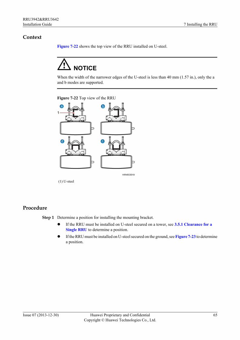
ContextFigure 7-22 shows the top view of the RRU installed on U-steel.
NOTICEWhen the width of the narrower edges of the U-steel is less than 40 mm (1.57 in.), only the aand b modes are supported.
Figure 7-22 Top view of the RRU
(1) U-steel
Procedure
Step 1 Determine a position for installing the mounting bracket.l If the RRU must be installed on U-steel secured on a tower, see 3.5.1 Clearance for a
Single RRU to determine a position.l If the RRU must be installed on U-steel secured on the ground, see Figure 7-23 to determine
a position.
RRU3942&RRU3642Installation Guide 7 Installing the RRU
Issue 07 (2013-12-30) Huawei Proprietary and ConfidentialCopyright © Huawei Technologies Co., Ltd.
65
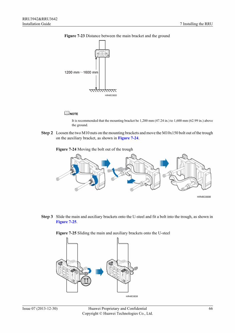
Figure 7-23 Distance between the main bracket and the ground
NOTE
It is recommended that the mounting bracket be 1,200 mm (47.24 in.) to 1,600 mm (62.99 in.) abovethe ground.
Step 2 Loosen the two M10 nuts on the mounting brackets and move the M10x150 bolt out of the troughon the auxiliary bracket, as shown in Figure 7-24.
Figure 7-24 Moving the bolt out of the trough
Step 3 Slide the main and auxiliary brackets onto the U-steel and fit a bolt into the trough, as shown inFigure 7-25.
Figure 7-25 Sliding the main and auxiliary brackets onto the U-steel
RRU3942&RRU3642Installation Guide 7 Installing the RRU
Issue 07 (2013-12-30) Huawei Proprietary and ConfidentialCopyright © Huawei Technologies Co., Ltd.
66
NOTICEEnsure that the arrows on the main bracket are pointing up.
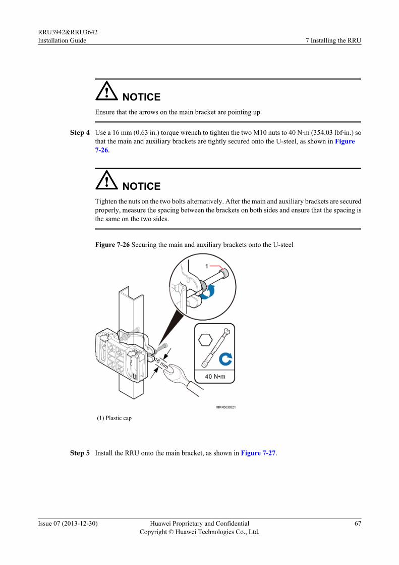
Step 4 Use a 16 mm (0.63 in.) torque wrench to tighten the two M10 nuts to 40 N·m (354.03 lbf·in.) sothat the main and auxiliary brackets are tightly secured onto the U-steel, as shown in Figure7-26.
NOTICETighten the nuts on the two bolts alternatively. After the main and auxiliary brackets are securedproperly, measure the spacing between the brackets on both sides and ensure that the spacing isthe same on the two sides.
Figure 7-26 Securing the main and auxiliary brackets onto the U-steel
(1) Plastic cap
Step 5 Install the RRU onto the main bracket, as shown in Figure 7-27.
RRU3942&RRU3642Installation Guide 7 Installing the RRU
Issue 07 (2013-12-30) Huawei Proprietary and ConfidentialCopyright © Huawei Technologies Co., Ltd.
67
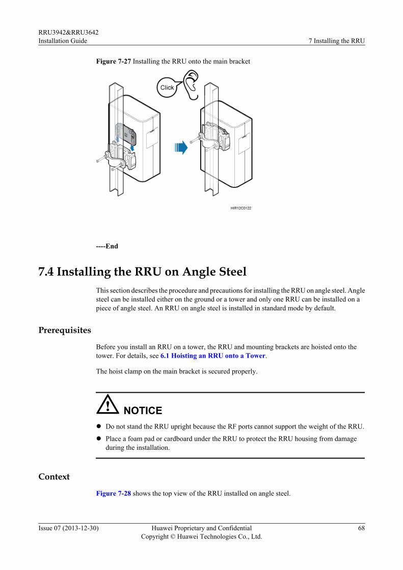
Figure 7-27 Installing the RRU onto the main bracket
----End
7.4 Installing the RRU on Angle SteelThis section describes the procedure and precautions for installing the RRU on angle steel. Anglesteel can be installed either on the ground or a tower and only one RRU can be installed on apiece of angle steel. An RRU on angle steel is installed in standard mode by default.
Prerequisites
Before you install an RRU on a tower, the RRU and mounting brackets are hoisted onto thetower. For details, see 6.1 Hoisting an RRU onto a Tower.
The hoist clamp on the main bracket is secured properly.
NOTICEl Do not stand the RRU upright because the RF ports cannot support the weight of the RRU.
l Place a foam pad or cardboard under the RRU to protect the RRU housing from damageduring the installation.
Context
Figure 7-28 shows the top view of the RRU installed on angle steel.
RRU3942&RRU3642Installation Guide 7 Installing the RRU
Issue 07 (2013-12-30) Huawei Proprietary and ConfidentialCopyright © Huawei Technologies Co., Ltd.
68
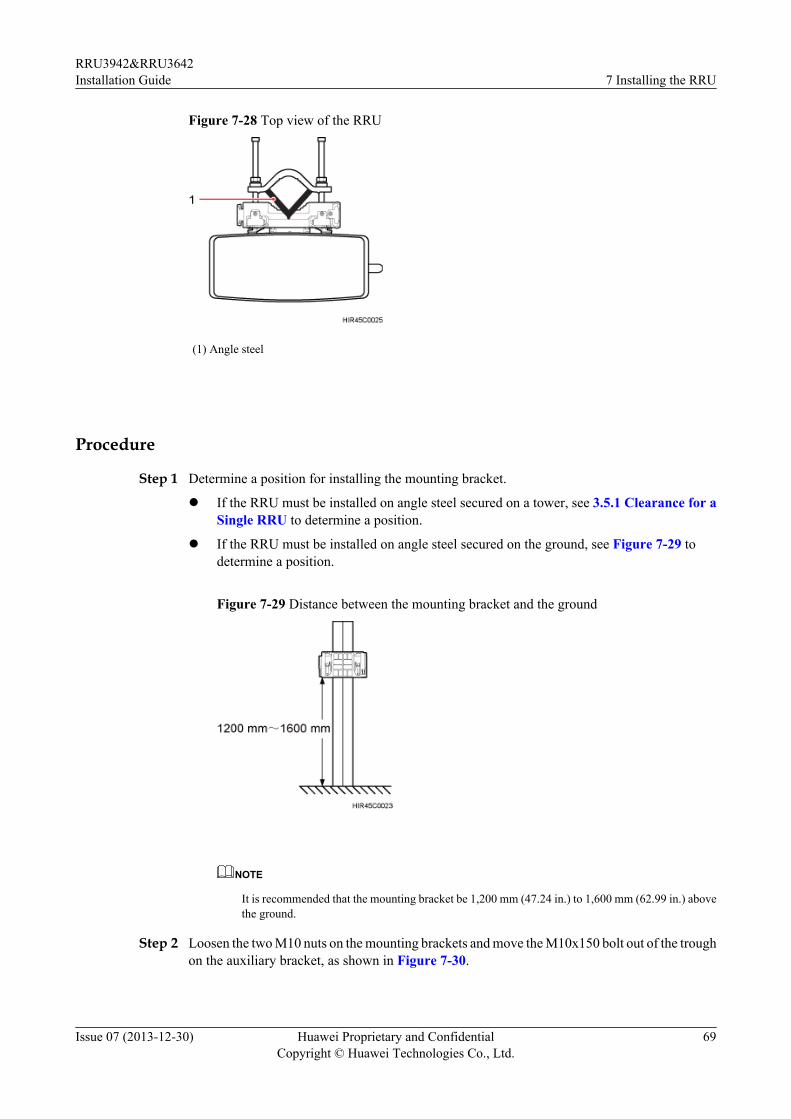
Figure 7-28 Top view of the RRU
(1) Angle steel
Procedure
Step 1 Determine a position for installing the mounting bracket.
l If the RRU must be installed on angle steel secured on a tower, see 3.5.1 Clearance for aSingle RRU to determine a position.
l If the RRU must be installed on angle steel secured on the ground, see Figure 7-29 todetermine a position.
Figure 7-29 Distance between the mounting bracket and the ground
NOTE
It is recommended that the mounting bracket be 1,200 mm (47.24 in.) to 1,600 mm (62.99 in.) abovethe ground.
Step 2 Loosen the two M10 nuts on the mounting brackets and move the M10x150 bolt out of the troughon the auxiliary bracket, as shown in Figure 7-30.
RRU3942&RRU3642Installation Guide 7 Installing the RRU
Issue 07 (2013-12-30) Huawei Proprietary and ConfidentialCopyright © Huawei Technologies Co., Ltd.
69
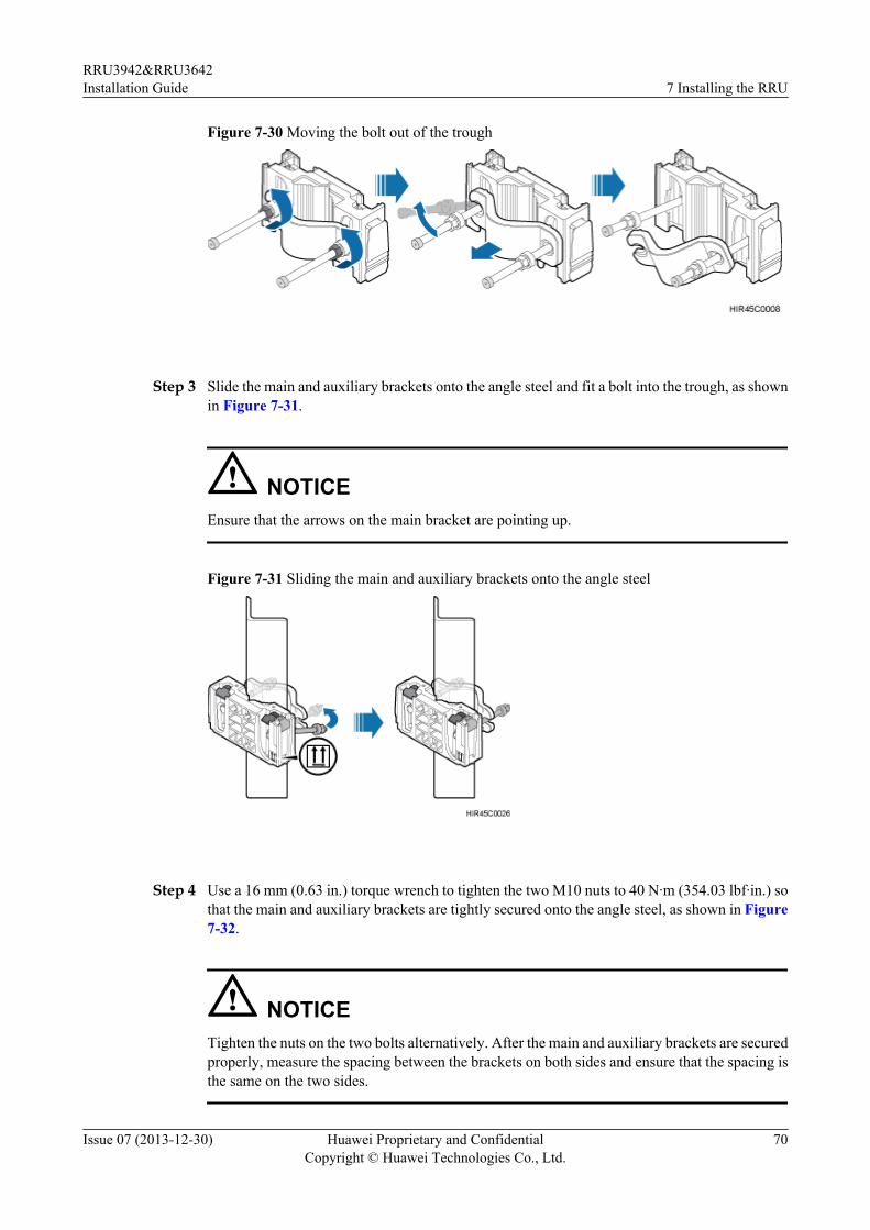
Figure 7-30 Moving the bolt out of the trough
Step 3 Slide the main and auxiliary brackets onto the angle steel and fit a bolt into the trough, as shownin Figure 7-31.
NOTICEEnsure that the arrows on the main bracket are pointing up.
Figure 7-31 Sliding the main and auxiliary brackets onto the angle steel
Step 4 Use a 16 mm (0.63 in.) torque wrench to tighten the two M10 nuts to 40 N·m (354.03 lbf·in.) sothat the main and auxiliary brackets are tightly secured onto the angle steel, as shown in Figure7-32.
NOTICETighten the nuts on the two bolts alternatively. After the main and auxiliary brackets are securedproperly, measure the spacing between the brackets on both sides and ensure that the spacing isthe same on the two sides.
RRU3942&RRU3642Installation Guide 7 Installing the RRU
Issue 07 (2013-12-30) Huawei Proprietary and ConfidentialCopyright © Huawei Technologies Co., Ltd.
70
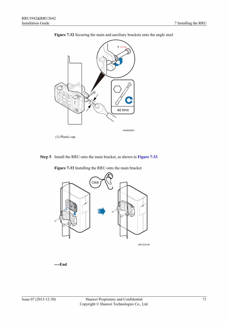
Figure 7-32 Securing the main and auxiliary brackets onto the angle steel
(1) Plastic cap
Step 5 Install the RRU onto the main bracket, as shown in Figure 7-33.
Figure 7-33 Installing the RRU onto the main bracket
----End
RRU3942&RRU3642Installation Guide 7 Installing the RRU
Issue 07 (2013-12-30) Huawei Proprietary and ConfidentialCopyright © Huawei Technologies Co., Ltd.
71
7.5 Installing the RRU on a WallThis section describes the procedure and precautions for installing the RRU on a wall. An RRUon a wall is installed in standard mode by default.
PrerequisitesThe hoist clamp on the main bracket is secured properly.
NOTICEl Do not stand the RRU upright because the RF ports cannot support the weight of the RRU.l Place a foam pad or cardboard under the RRU to protect the RRU housing from damage
during the installation.l When installing RRUs on a wall, do not combine the mounting brackets for multiple RRUs
together.
ContextThe wall on which RRUs are installed must meet the following requirements:l For each RRU, the wall must be able to bear a weight four times the RRU's weight and the
bolts' pulling force of 1.25 kN (281.25 lbf) vertical to the wall.l Expansion bolts must be tightened to 15 N·m (132.76 lbf·in.) so that the bolts stay secured
without damaging the wall.
Procedure
Step 1 Remove the plastic cap, M10 nut, spring washer, thick flat washer, auxiliary bracket, andM10x150 bolt one by one. Reserve the main bracket for the wall-mounted installation.
Step 2 Place the main bracket against the wall, use a level to verify that the main bracket is placedhorizontally, and use a maker to mark anchor points, as shown in Figure 7-34.
RRU3942&RRU3642Installation Guide 7 Installing the RRU
Issue 07 (2013-12-30) Huawei Proprietary and ConfidentialCopyright © Huawei Technologies Co., Ltd.
72
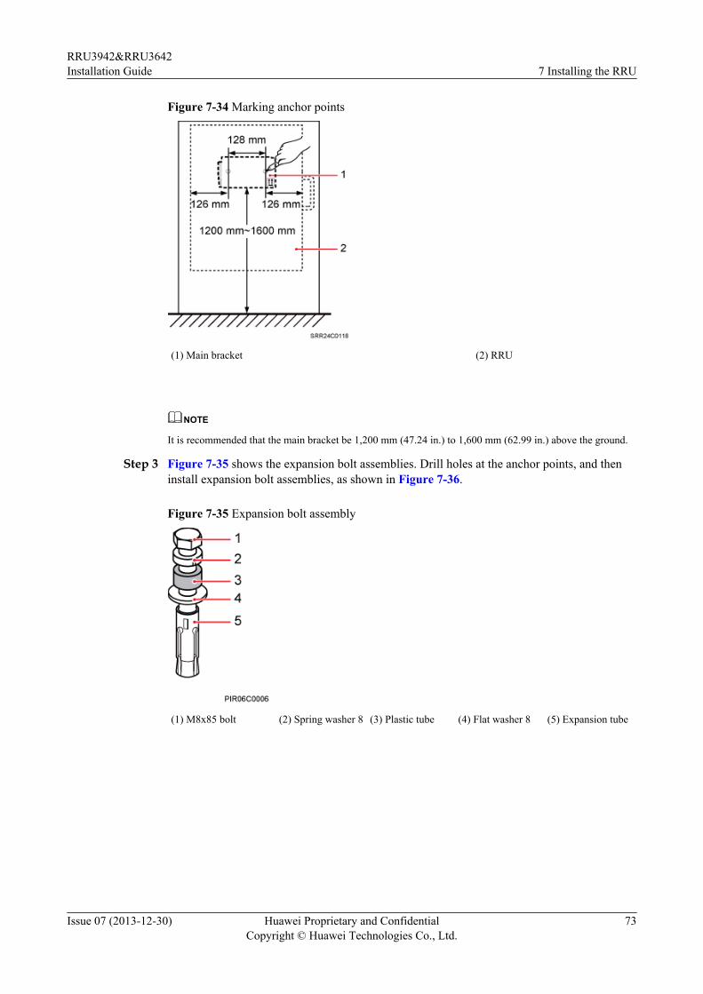
Figure 7-34 Marking anchor points
(1) Main bracket (2) RRU
NOTE
It is recommended that the main bracket be 1,200 mm (47.24 in.) to 1,600 mm (62.99 in.) above the ground.
Step 3 Figure 7-35 shows the expansion bolt assemblies. Drill holes at the anchor points, and theninstall expansion bolt assemblies, as shown in Figure 7-36.
Figure 7-35 Expansion bolt assembly
(1) M8x85 bolt (2) Spring washer 8 (3) Plastic tube (4) Flat washer 8 (5) Expansion tube
RRU3942&RRU3642Installation Guide 7 Installing the RRU
Issue 07 (2013-12-30) Huawei Proprietary and ConfidentialCopyright © Huawei Technologies Co., Ltd.
73
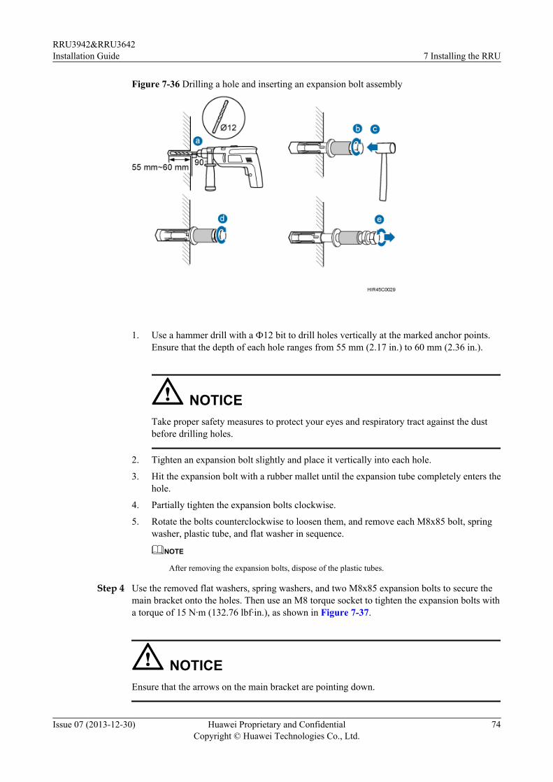
Figure 7-36 Drilling a hole and inserting an expansion bolt assembly
1. Use a hammer drill with a Ф12 bit to drill holes vertically at the marked anchor points.Ensure that the depth of each hole ranges from 55 mm (2.17 in.) to 60 mm (2.36 in.).
NOTICETake proper safety measures to protect your eyes and respiratory tract against the dustbefore drilling holes.
2. Tighten an expansion bolt slightly and place it vertically into each hole.
3. Hit the expansion bolt with a rubber mallet until the expansion tube completely enters thehole.
4. Partially tighten the expansion bolts clockwise.
5. Rotate the bolts counterclockwise to loosen them, and remove each M8x85 bolt, springwasher, plastic tube, and flat washer in sequence.
NOTE
After removing the expansion bolts, dispose of the plastic tubes.
Step 4 Use the removed flat washers, spring washers, and two M8x85 expansion bolts to secure themain bracket onto the holes. Then use an M8 torque socket to tighten the expansion bolts witha torque of 15 N·m (132.76 lbf·in.), as shown in Figure 7-37.
NOTICEEnsure that the arrows on the main bracket are pointing down.
RRU3942&RRU3642Installation Guide 7 Installing the RRU
Issue 07 (2013-12-30) Huawei Proprietary and ConfidentialCopyright © Huawei Technologies Co., Ltd.
74
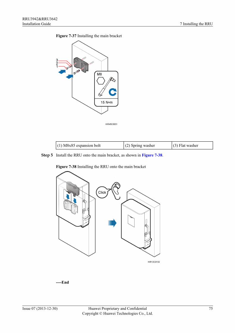
Figure 7-37 Installing the main bracket
(1) M8x85 expansion bolt (2) Spring washer (3) Flat washer
Step 5 Install the RRU onto the main bracket, as shown in Figure 7-38.
Figure 7-38 Installing the RRU onto the main bracket
----End
RRU3942&RRU3642Installation Guide 7 Installing the RRU
Issue 07 (2013-12-30) Huawei Proprietary and ConfidentialCopyright © Huawei Technologies Co., Ltd.
75
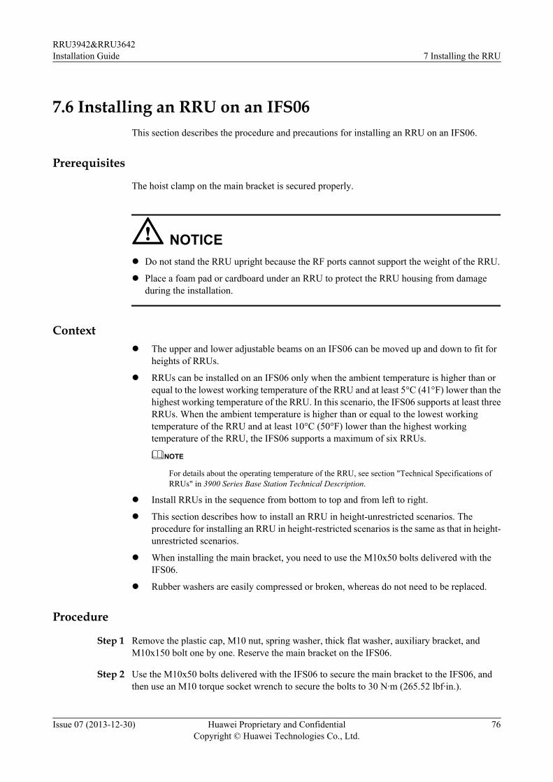
7.6 Installing an RRU on an IFS06This section describes the procedure and precautions for installing an RRU on an IFS06.
Prerequisites
The hoist clamp on the main bracket is secured properly.
NOTICEl Do not stand the RRU upright because the RF ports cannot support the weight of the RRU.
l Place a foam pad or cardboard under an RRU to protect the RRU housing from damageduring the installation.
Contextl The upper and lower adjustable beams on an IFS06 can be moved up and down to fit for
heights of RRUs.
l RRUs can be installed on an IFS06 only when the ambient temperature is higher than orequal to the lowest working temperature of the RRU and at least 5°C (41°F) lower than thehighest working temperature of the RRU. In this scenario, the IFS06 supports at least threeRRUs. When the ambient temperature is higher than or equal to the lowest workingtemperature of the RRU and at least 10°C (50°F) lower than the highest workingtemperature of the RRU, the IFS06 supports a maximum of six RRUs.
NOTE
For details about the operating temperature of the RRU, see section "Technical Specifications ofRRUs" in 3900 Series Base Station Technical Description.
l Install RRUs in the sequence from bottom to top and from left to right.
l This section describes how to install an RRU in height-unrestricted scenarios. Theprocedure for installing an RRU in height-restricted scenarios is the same as that in height-unrestricted scenarios.
l When installing the main bracket, you need to use the M10x50 bolts delivered with theIFS06.
l Rubber washers are easily compressed or broken, whereas do not need to be replaced.
Procedure
Step 1 Remove the plastic cap, M10 nut, spring washer, thick flat washer, auxiliary bracket, andM10x150 bolt one by one. Reserve the main bracket on the IFS06.
Step 2 Use the M10x50 bolts delivered with the IFS06 to secure the main bracket to the IFS06, andthen use an M10 torque socket wrench to secure the bolts to 30 N·m (265.52 lbf·in.).
RRU3942&RRU3642Installation Guide 7 Installing the RRU
Issue 07 (2013-12-30) Huawei Proprietary and ConfidentialCopyright © Huawei Technologies Co., Ltd.
76
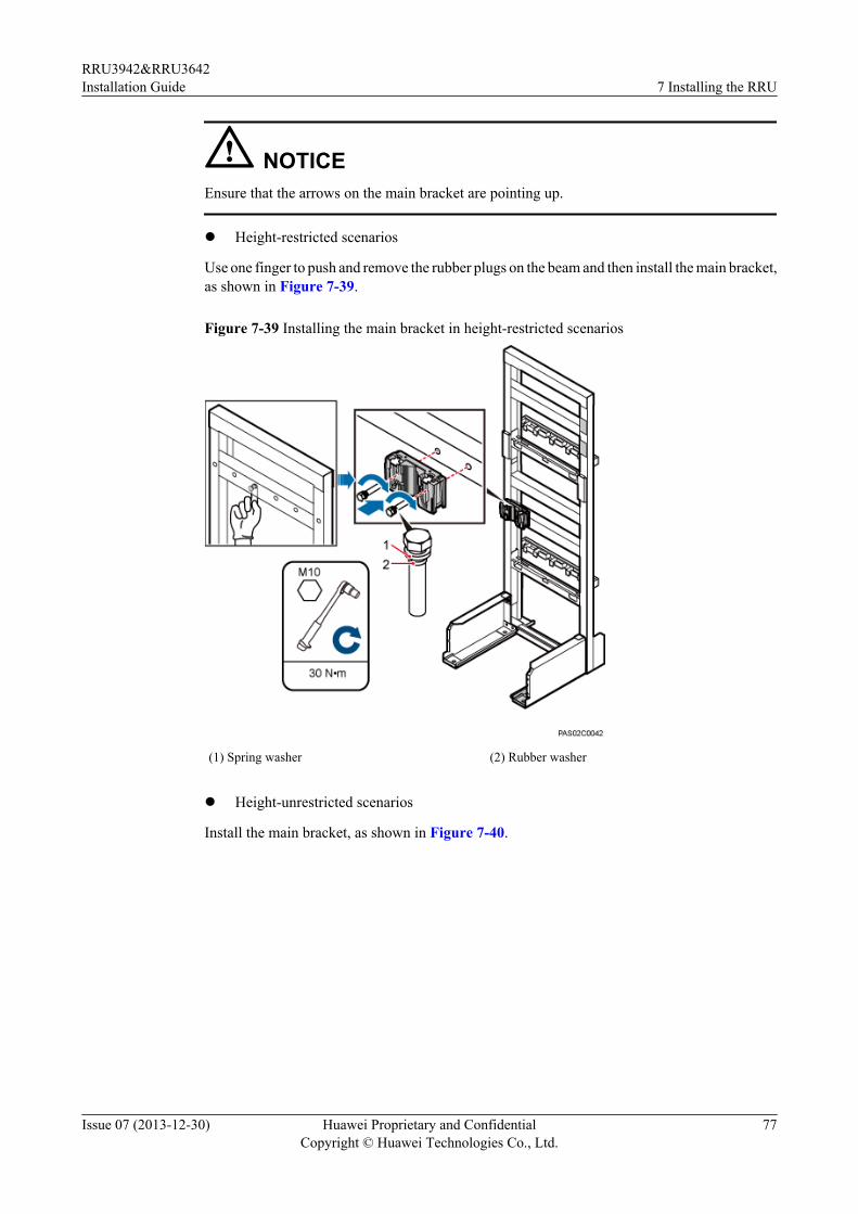
NOTICEEnsure that the arrows on the main bracket are pointing up.
l Height-restricted scenarios
Use one finger to push and remove the rubber plugs on the beam and then install the main bracket,as shown in Figure 7-39.
Figure 7-39 Installing the main bracket in height-restricted scenarios
(1) Spring washer (2) Rubber washer
l Height-unrestricted scenarios
Install the main bracket, as shown in Figure 7-40.
RRU3942&RRU3642Installation Guide 7 Installing the RRU
Issue 07 (2013-12-30) Huawei Proprietary and ConfidentialCopyright © Huawei Technologies Co., Ltd.
77
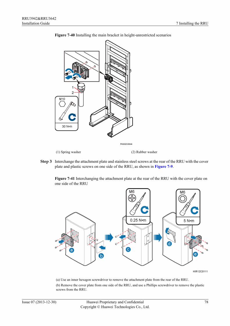
Figure 7-40 Installing the main bracket in height-unrestricted scenarios
(1) Spring washer (2) Rubber washer
Step 3 Interchange the attachment plate and stainless steel screws at the rear of the RRU with the coverplate and plastic screws on one side of the RRU, as shown in Figure 7-9.
Figure 7-41 Interchanging the attachment plate at the rear of the RRU with the cover plate onone side of the RRU
(a) Use an inner hexagon screwdriver to remove the attachment plate from the rear of the RRU.(b) Remove the cover plate from one side of the RRU, and use a Phillips screwdriver to remove the plasticscrews from the RRU.
RRU3942&RRU3642Installation Guide 7 Installing the RRU
Issue 07 (2013-12-30) Huawei Proprietary and ConfidentialCopyright © Huawei Technologies Co., Ltd.
78
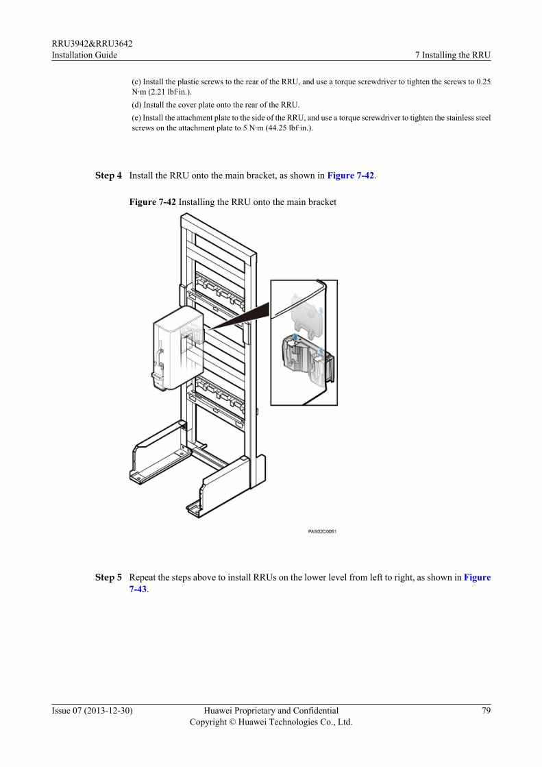
(c) Install the plastic screws to the rear of the RRU, and use a torque screwdriver to tighten the screws to 0.25N·m (2.21 lbf·in.).(d) Install the cover plate onto the rear of the RRU.(e) Install the attachment plate to the side of the RRU, and use a torque screwdriver to tighten the stainless steelscrews on the attachment plate to 5 N·m (44.25 lbf·in.).
Step 4 Install the RRU onto the main bracket, as shown in Figure 7-42.
Figure 7-42 Installing the RRU onto the main bracket
Step 5 Repeat the steps above to install RRUs on the lower level from left to right, as shown in Figure7-43.
RRU3942&RRU3642Installation Guide 7 Installing the RRU
Issue 07 (2013-12-30) Huawei Proprietary and ConfidentialCopyright © Huawei Technologies Co., Ltd.
79
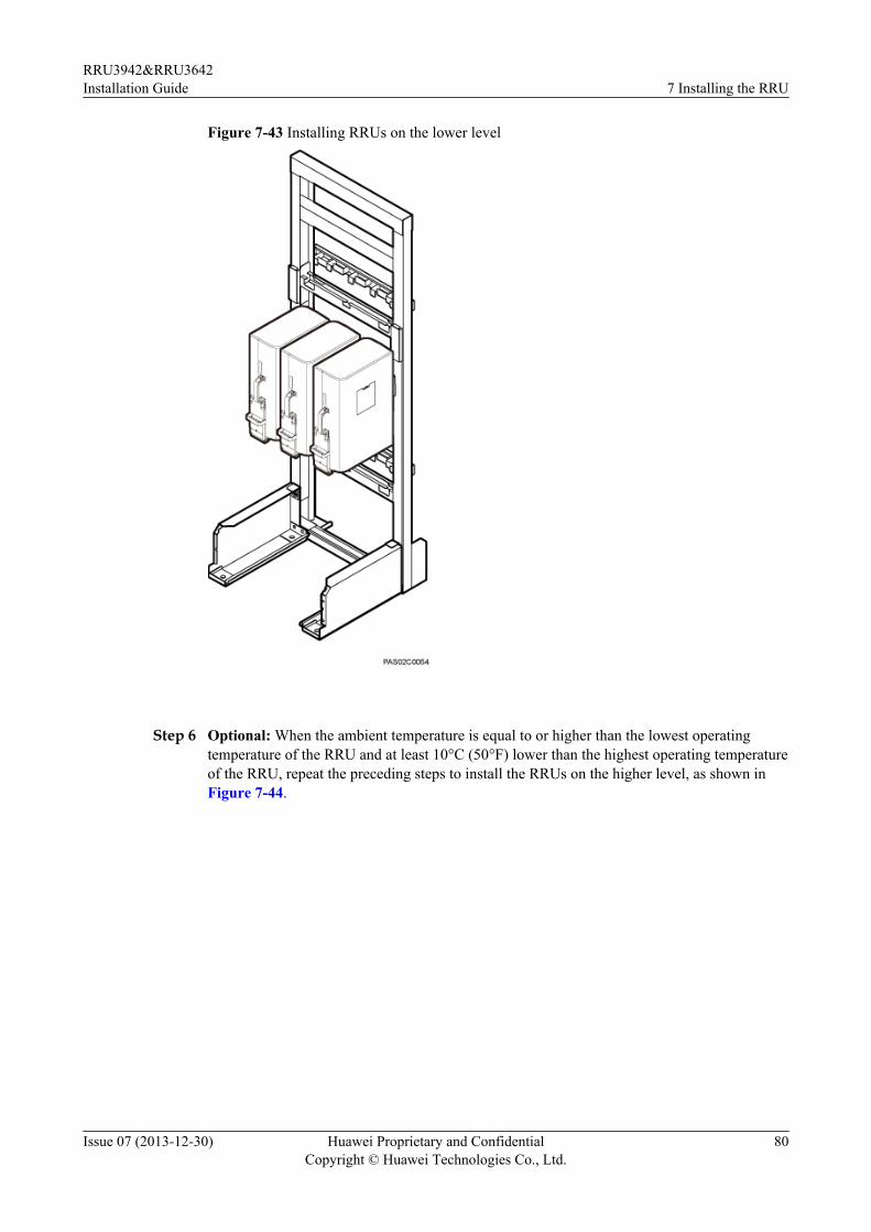
Figure 7-43 Installing RRUs on the lower level
Step 6 Optional: When the ambient temperature is equal to or higher than the lowest operatingtemperature of the RRU and at least 10°C (50°F) lower than the highest operating temperatureof the RRU, repeat the preceding steps to install the RRUs on the higher level, as shown inFigure 7-44.
RRU3942&RRU3642Installation Guide 7 Installing the RRU
Issue 07 (2013-12-30) Huawei Proprietary and ConfidentialCopyright © Huawei Technologies Co., Ltd.
80
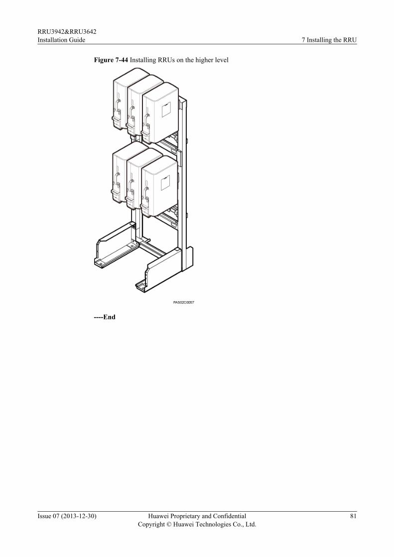
Figure 7-44 Installing RRUs on the higher level
----End
RRU3942&RRU3642Installation Guide 7 Installing the RRU
Issue 07 (2013-12-30) Huawei Proprietary and ConfidentialCopyright © Huawei Technologies Co., Ltd.
81
8 Installing RRU Cables
About This Chapter
This chapter describes the procedure for installing RRU cables.
8.1 Cabling RequirementsCables must be routed according to the specified cabling requirements to prevent signalinterference.
8.2 Cable ConnectionsThis section describes the cable connections for a single RRU and multiple RRUs.
8.3 Installation ProcessThis section describes the process of installing RRU cables.
8.4 RRU Cable ListThis section describes RRU cable connections.
8.5 Installing an RRU PGND CableThis section describes the procedure for installing an RRU PGND cable.
8.6 Installing an RRU RF JumperThis section describes the procedure for installing an RRU RF jumper.
8.7 Installing an Inter-RRU RF CableThis section describes the procedure for installing an inter-RRU RF cable.
8.8 Installing an RRU AISG Multi-Wire Cable and AISG Extension CableThis section describes the procedures for installing an RRU AISG multi-wire cable and AISGextension cable.
8.9 Opening the Cover Plate of an RRU Cabling CavityThis section describes the procedure for opening the cover plate of an RRU cabling cavity.
8.10 Installing an RRU Power CableThis section describes the procedure for installing an RRU power cable.
8.11 Installing a CPRI Fiber Optic CableThis section describes the procedure for installing a CPRI fiber optic cable.
8.12 Installing an RRU Alarm Cable
RRU3942&RRU3642Installation Guide 8 Installing RRU Cables
Issue 07 (2013-12-30) Huawei Proprietary and ConfidentialCopyright © Huawei Technologies Co., Ltd.
82
This section describes the procedure for installing an RRU alarm cable.
8.13 Closing the Cover Plate of an RRU Cabling CavityThis section describes the procedure for closing the cover plate of an RRU cabling cavity.
RRU3942&RRU3642Installation Guide 8 Installing RRU Cables
Issue 07 (2013-12-30) Huawei Proprietary and ConfidentialCopyright © Huawei Technologies Co., Ltd.
83
8.1 Cabling RequirementsCables must be routed according to the specified cabling requirements to prevent signalinterference.
NOTE
If a cable listed below is not required, skip the routing requirements of the cable.
General Cabling RequirementsRequirements for Bending Radiusl The bending radius of the 7/8'' feeder must be more than 250 mm (9.84 in.), and the bending
radius of the 5/4'' feeder must be more than 380 mm (14.96 in.).l The bending radius of the 1/4'' jumper must be more than 35 mm (1.38 in.). The bending
radius of the super-flexible 1/2'' jumper must be more than 50 mm (1.97 in.), and the bendingradius of the ordinary 1/2'' jumper must be more than 127 mm (5 in.).
l The bending radius of the power cable or PGND cable must be at least three times thediameter of the cable.
l The bending radius of a fiber optic cable is at least 20 times the diameter of the fiber opticcable, and the minimum bending radius of the breakout cable at each end of the fiber opticcable is 30 mm (1.18 in.).
l The bending radius of the E1/T1 cable must be at least three times the diameter of the cable.l The bending radius of the signal cable must be at least five times the diameter of the cable.
Requirements for Cable Bindingl The same types of cable must be bound together.l Different types of cable must be separately routed with the minimum spacing of 30 mm
(1.18 in.) and cannot be entangled.l The cables must be bound tightly and neatly. The sheaths of the cables must not be damaged.l Cable ties are installed in the same direction, and those at the same horizontal line must be
in a straight line.l The excess of indoor cable ties is trimmed off, and the excess of outdoor cable ties allows
about 5 mm (0.2 in.), without remaining rough edges.l Labels or nameplates must be attached to both ends, joints, or turns of cables after they are
installed.
Security Requirementsl Cables should be placed away from sharp objects or wall burrs. If these positions are
inevitable, protect the cables with protection pipes.l Cables must be routed away from heat sources, or heat-insulation materials are added
between cables and heat sources.l Sufficient slack (recommended for about 0.1 m [0.33 ft]) is provided in cables at turns or
the position close to a device, facilitating cable and device maintenance.
Indoor Cabling Requirementsl Cables are routed indoors through the feeder window.
RRU3942&RRU3642Installation Guide 8 Installing RRU Cables
Issue 07 (2013-12-30) Huawei Proprietary and ConfidentialCopyright © Huawei Technologies Co., Ltd.
84
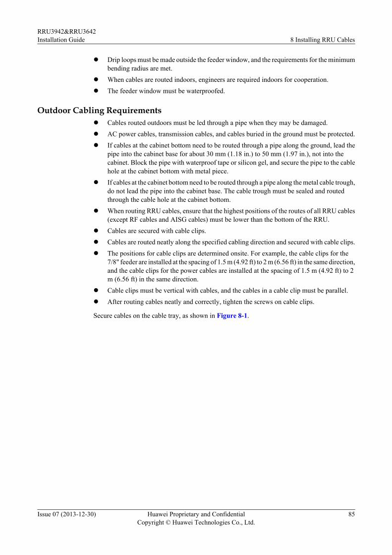
l Drip loops must be made outside the feeder window, and the requirements for the minimumbending radius are met.
l When cables are routed indoors, engineers are required indoors for cooperation.l The feeder window must be waterproofed.
Outdoor Cabling Requirementsl Cables routed outdoors must be led through a pipe when they may be damaged.l AC power cables, transmission cables, and cables buried in the ground must be protected.l If cables at the cabinet bottom need to be routed through a pipe along the ground, lead the
pipe into the cabinet base for about 30 mm (1.18 in.) to 50 mm (1.97 in.), not into thecabinet. Block the pipe with waterproof tape or silicon gel, and secure the pipe to the cablehole at the cabinet bottom with metal piece.
l If cables at the cabinet bottom need to be routed through a pipe along the metal cable trough,do not lead the pipe into the cabinet base. The cable trough must be sealed and routedthrough the cable hole at the cabinet bottom.
l When routing RRU cables, ensure that the highest positions of the routes of all RRU cables(except RF cables and AISG cables) must be lower than the bottom of the RRU.
l Cables are secured with cable clips.l Cables are routed neatly along the specified cabling direction and secured with cable clips.l The positions for cable clips are determined onsite. For example, the cable clips for the
7/8" feeder are installed at the spacing of 1.5 m (4.92 ft) to 2 m (6.56 ft) in the same direction,and the cable clips for the power cables are installed at the spacing of 1.5 m (4.92 ft) to 2m (6.56 ft) in the same direction.
l Cable clips must be vertical with cables, and the cables in a cable clip must be parallel.l After routing cables neatly and correctly, tighten the screws on cable clips.
Secure cables on the cable tray, as shown in Figure 8-1.
RRU3942&RRU3642Installation Guide 8 Installing RRU Cables
Issue 07 (2013-12-30) Huawei Proprietary and ConfidentialCopyright © Huawei Technologies Co., Ltd.
85
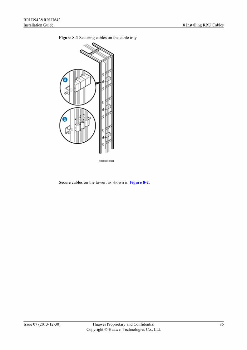
Figure 8-1 Securing cables on the cable tray
Secure cables on the tower, as shown in Figure 8-2.
RRU3942&RRU3642Installation Guide 8 Installing RRU Cables
Issue 07 (2013-12-30) Huawei Proprietary and ConfidentialCopyright © Huawei Technologies Co., Ltd.
86
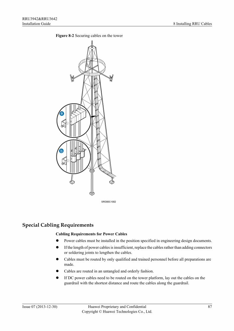
Figure 8-2 Securing cables on the tower
Special Cabling RequirementsCabling Requirements for Power Cablesl Power cables must be installed in the position specified in engineering design documents.l If the length of power cables is insufficient, replace the cables rather than adding connectors
or soldering joints to lengthen the cables.l Cables must be routed by only qualified and trained personnel before all preparations are
made.l Cables are routed in an untangled and orderly fashion.l If DC power cables need to be routed on the tower platform, lay out the cables on the
guardrail with the shortest distance and route the cables along the guardrail.
RRU3942&RRU3642Installation Guide 8 Installing RRU Cables
Issue 07 (2013-12-30) Huawei Proprietary and ConfidentialCopyright © Huawei Technologies Co., Ltd.
87
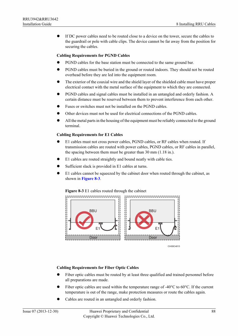
l If DC power cables need to be routed close to a device on the tower, secure the cables tothe guardrail or pole with cable clips. The device cannot be far away from the position forsecuring the cables.
Cabling Requirements for PGND Cables
l PGND cables for the base station must be connected to the same ground bar.
l PGND cables must be buried in the ground or routed indoors. They should not be routedoverhead before they are led into the equipment room.
l The exterior of the coaxial wire and the shield layer of the shielded cable must have properelectrical contact with the metal surface of the equipment to which they are connected.
l PGND cables and signal cables must be installed in an untangled and orderly fashion. Acertain distance must be reserved between them to prevent interference from each other.
l Fuses or switches must not be installed on the PGND cables.
l Other devices must not be used for electrical connections of the PGND cables.
l All the metal parts in the housing of the equipment must be reliably connected to the groundterminal.
Cabling Requirements for E1 Cables
l E1 cables must not cross power cables, PGND cables, or RF cables when routed. Iftransmission cables are routed with power cables, PGND cables, or RF cables in parallel,the spacing between them must be greater than 30 mm (1.18 in.).
l E1 cables are routed straightly and bound neatly with cable ties.
l Sufficient slack is provided in E1 cables at turns.
l E1 cables cannot be squeezed by the cabinet door when routed through the cabinet, asshown in Figure 8-3.
Figure 8-3 E1 cables routed through the cabinet
Cabling Requirements for Fiber Optic Cables
l Fiber optic cables must be routed by at least three qualified and trained personnel beforeall preparations are made.
l Fiber optic cables are used within the temperature range of -40°C to 60°C. If the currenttemperature is out of the range, make protection measures or route the cables again.
l Cables are routed in an untangled and orderly fashion.
RRU3942&RRU3642Installation Guide 8 Installing RRU Cables
Issue 07 (2013-12-30) Huawei Proprietary and ConfidentialCopyright © Huawei Technologies Co., Ltd.
88
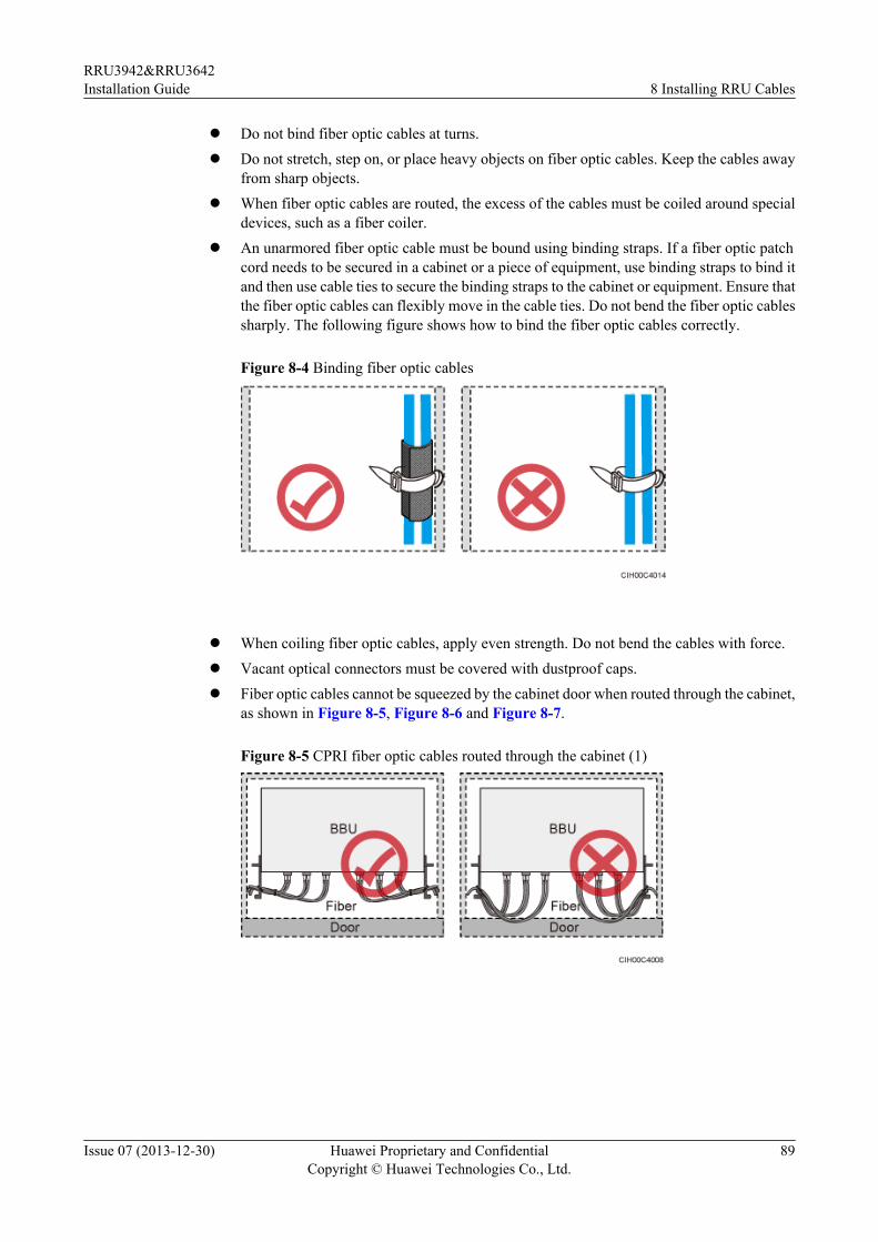
l Do not bind fiber optic cables at turns.l Do not stretch, step on, or place heavy objects on fiber optic cables. Keep the cables away
from sharp objects.l When fiber optic cables are routed, the excess of the cables must be coiled around special
devices, such as a fiber coiler.l An unarmored fiber optic cable must be bound using binding straps. If a fiber optic patch
cord needs to be secured in a cabinet or a piece of equipment, use binding straps to bind itand then use cable ties to secure the binding straps to the cabinet or equipment. Ensure thatthe fiber optic cables can flexibly move in the cable ties. Do not bend the fiber optic cablessharply. The following figure shows how to bind the fiber optic cables correctly.
Figure 8-4 Binding fiber optic cables
l When coiling fiber optic cables, apply even strength. Do not bend the cables with force.l Vacant optical connectors must be covered with dustproof caps.l Fiber optic cables cannot be squeezed by the cabinet door when routed through the cabinet,
as shown in Figure 8-5, Figure 8-6 and Figure 8-7.
Figure 8-5 CPRI fiber optic cables routed through the cabinet (1)
RRU3942&RRU3642Installation Guide 8 Installing RRU Cables
Issue 07 (2013-12-30) Huawei Proprietary and ConfidentialCopyright © Huawei Technologies Co., Ltd.
89
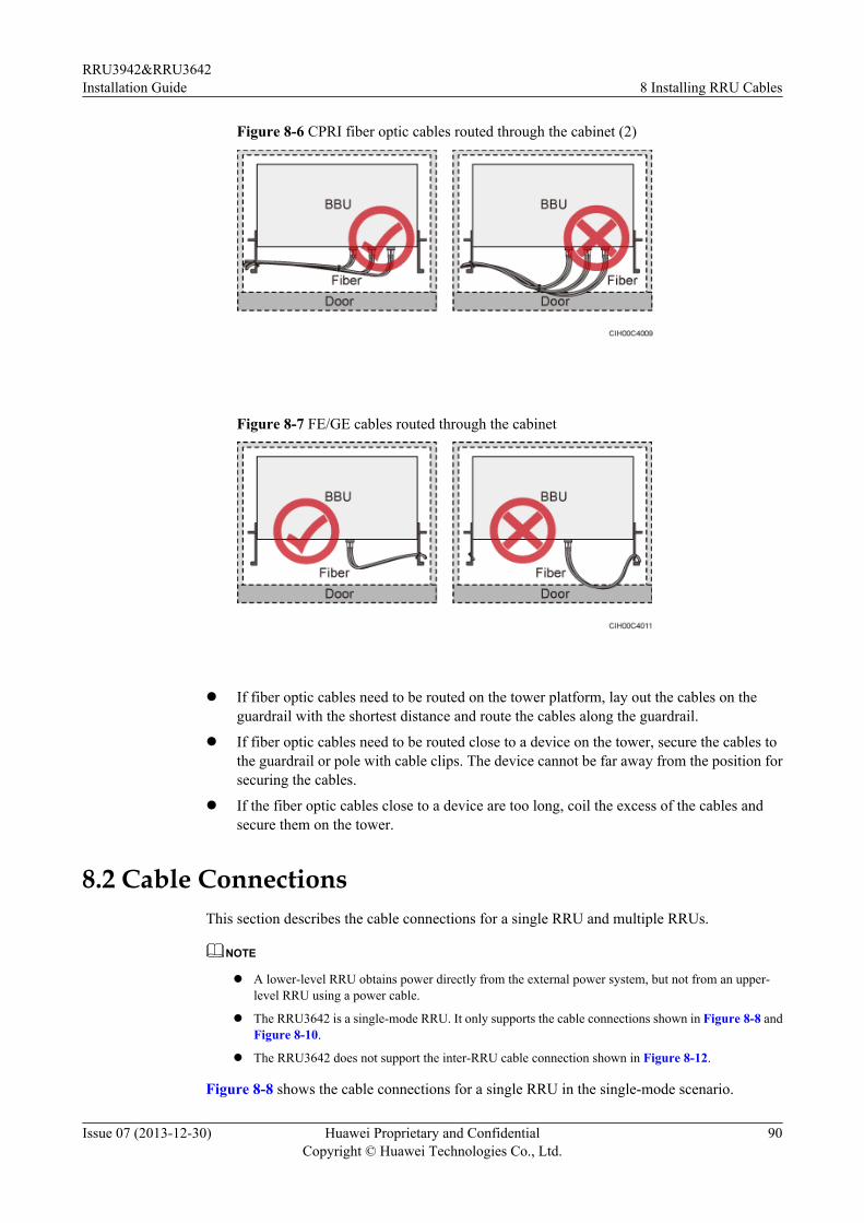
Figure 8-6 CPRI fiber optic cables routed through the cabinet (2)
Figure 8-7 FE/GE cables routed through the cabinet
l If fiber optic cables need to be routed on the tower platform, lay out the cables on theguardrail with the shortest distance and route the cables along the guardrail.
l If fiber optic cables need to be routed close to a device on the tower, secure the cables tothe guardrail or pole with cable clips. The device cannot be far away from the position forsecuring the cables.
l If the fiber optic cables close to a device are too long, coil the excess of the cables andsecure them on the tower.
8.2 Cable ConnectionsThis section describes the cable connections for a single RRU and multiple RRUs.
NOTE
l A lower-level RRU obtains power directly from the external power system, but not from an upper-level RRU using a power cable.
l The RRU3642 is a single-mode RRU. It only supports the cable connections shown in Figure 8-8 andFigure 8-10.
l The RRU3642 does not support the inter-RRU cable connection shown in Figure 8-12.
Figure 8-8 shows the cable connections for a single RRU in the single-mode scenario.
RRU3942&RRU3642Installation Guide 8 Installing RRU Cables
Issue 07 (2013-12-30) Huawei Proprietary and ConfidentialCopyright © Huawei Technologies Co., Ltd.
90
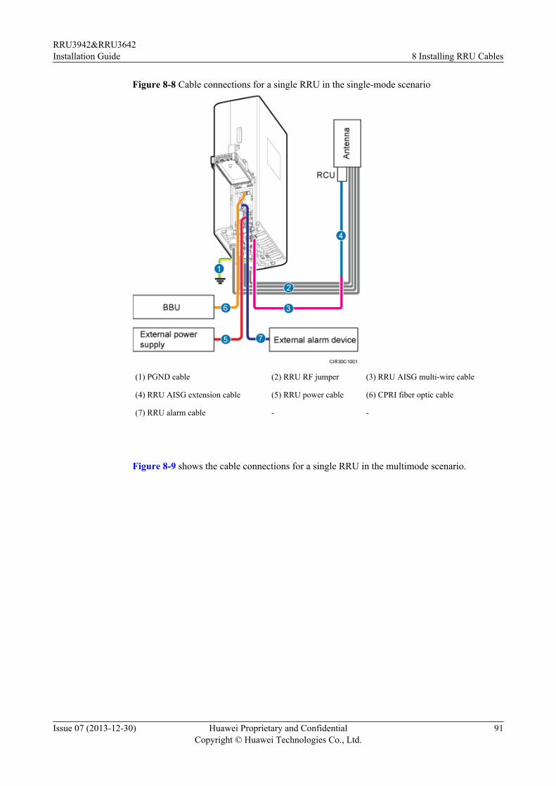
Figure 8-8 Cable connections for a single RRU in the single-mode scenario
(1) PGND cable (2) RRU RF jumper (3) RRU AISG multi-wire cable
(4) RRU AISG extension cable (5) RRU power cable (6) CPRI fiber optic cable
(7) RRU alarm cable - -
Figure 8-9 shows the cable connections for a single RRU in the multimode scenario.
RRU3942&RRU3642Installation Guide 8 Installing RRU Cables
Issue 07 (2013-12-30) Huawei Proprietary and ConfidentialCopyright © Huawei Technologies Co., Ltd.
91
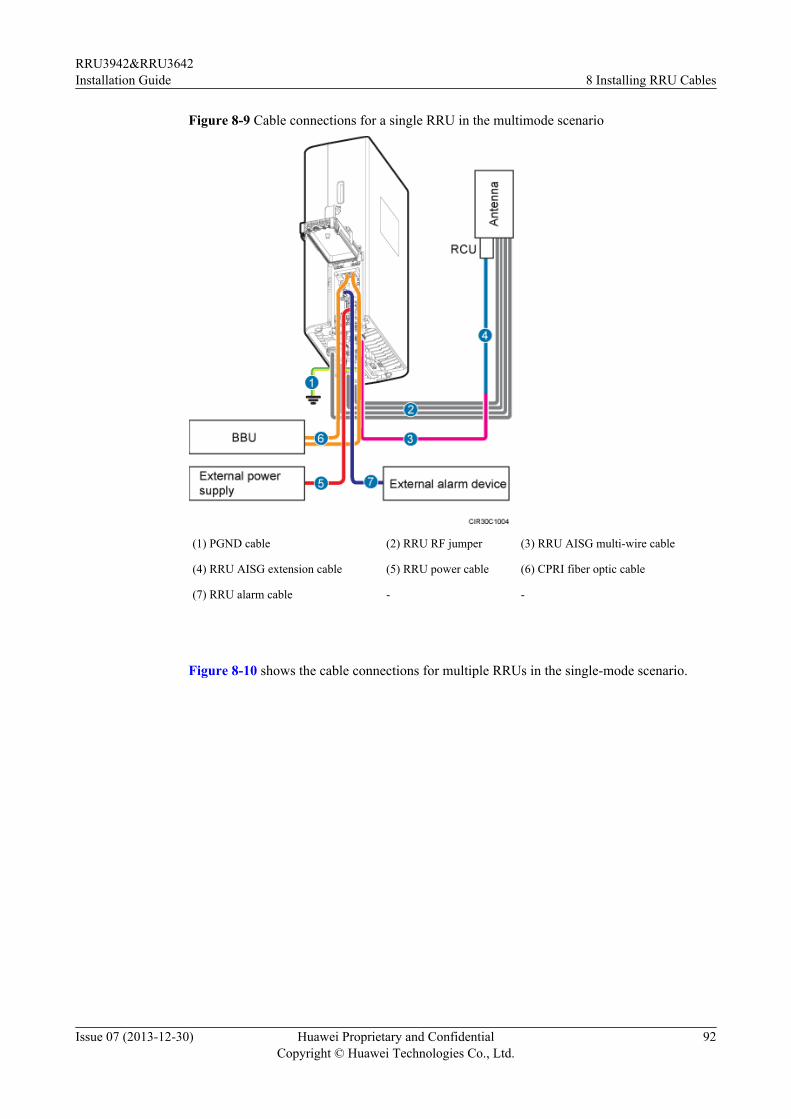
Figure 8-9 Cable connections for a single RRU in the multimode scenario
(1) PGND cable (2) RRU RF jumper (3) RRU AISG multi-wire cable
(4) RRU AISG extension cable (5) RRU power cable (6) CPRI fiber optic cable
(7) RRU alarm cable - -
Figure 8-10 shows the cable connections for multiple RRUs in the single-mode scenario.
RRU3942&RRU3642Installation Guide 8 Installing RRU Cables
Issue 07 (2013-12-30) Huawei Proprietary and ConfidentialCopyright © Huawei Technologies Co., Ltd.
92
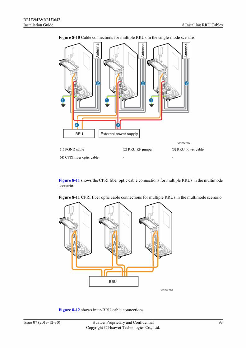
Figure 8-10 Cable connections for multiple RRUs in the single-mode scenario
(1) PGND cable (2) RRU RF jumper (3) RRU power cable
(4) CPRI fiber optic cable - -
Figure 8-11 shows the CPRI fiber optic cable connections for multiple RRUs in the multimodescenario.
Figure 8-11 CPRI fiber optic cable connections for multiple RRUs in the multimode scenario
Figure 8-12 shows inter-RRU cable connections.
RRU3942&RRU3642Installation Guide 8 Installing RRU Cables
Issue 07 (2013-12-30) Huawei Proprietary and ConfidentialCopyright © Huawei Technologies Co., Ltd.
93
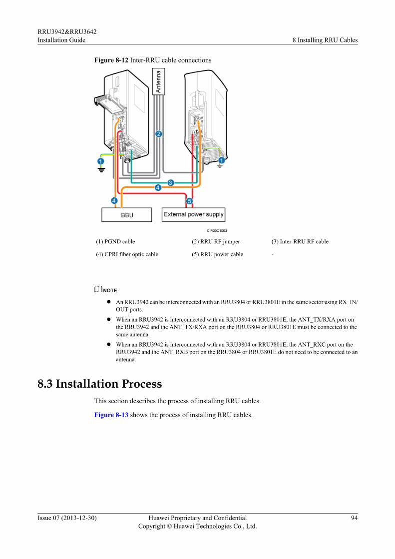
Figure 8-12 Inter-RRU cable connections
(1) PGND cable (2) RRU RF jumper (3) Inter-RRU RF cable
(4) CPRI fiber optic cable (5) RRU power cable -
NOTE
l An RRU3942 can be interconnected with an RRU3804 or RRU3801E in the same sector using RX_IN/OUT ports.
l When an RRU3942 is interconnected with an RRU3804 or RRU3801E, the ANT_TX/RXA port onthe RRU3942 and the ANT_TX/RXA port on the RRU3804 or RRU3801E must be connected to thesame antenna.
l When an RRU3942 is interconnected with an RRU3804 or RRU3801E, the ANT_RXC port on theRRU3942 and the ANT_RXB port on the RRU3804 or RRU3801E do not need to be connected to anantenna.
8.3 Installation ProcessThis section describes the process of installing RRU cables.
Figure 8-13 shows the process of installing RRU cables.
RRU3942&RRU3642Installation Guide 8 Installing RRU Cables
Issue 07 (2013-12-30) Huawei Proprietary and ConfidentialCopyright © Huawei Technologies Co., Ltd.
94
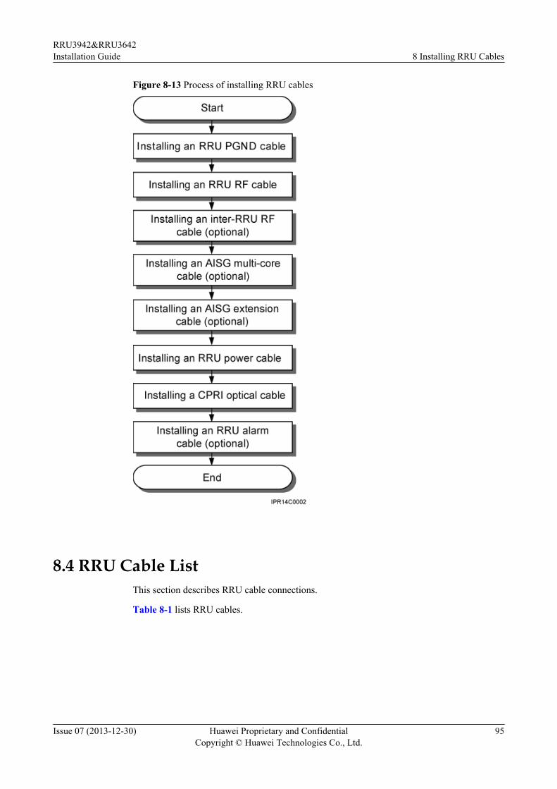
Figure 8-13 Process of installing RRU cables
8.4 RRU Cable ListThis section describes RRU cable connections.
Table 8-1 lists RRU cables.
RRU3942&RRU3642Installation Guide 8 Installing RRU Cables
Issue 07 (2013-12-30) Huawei Proprietary and ConfidentialCopyright © Huawei Technologies Co., Ltd.
95
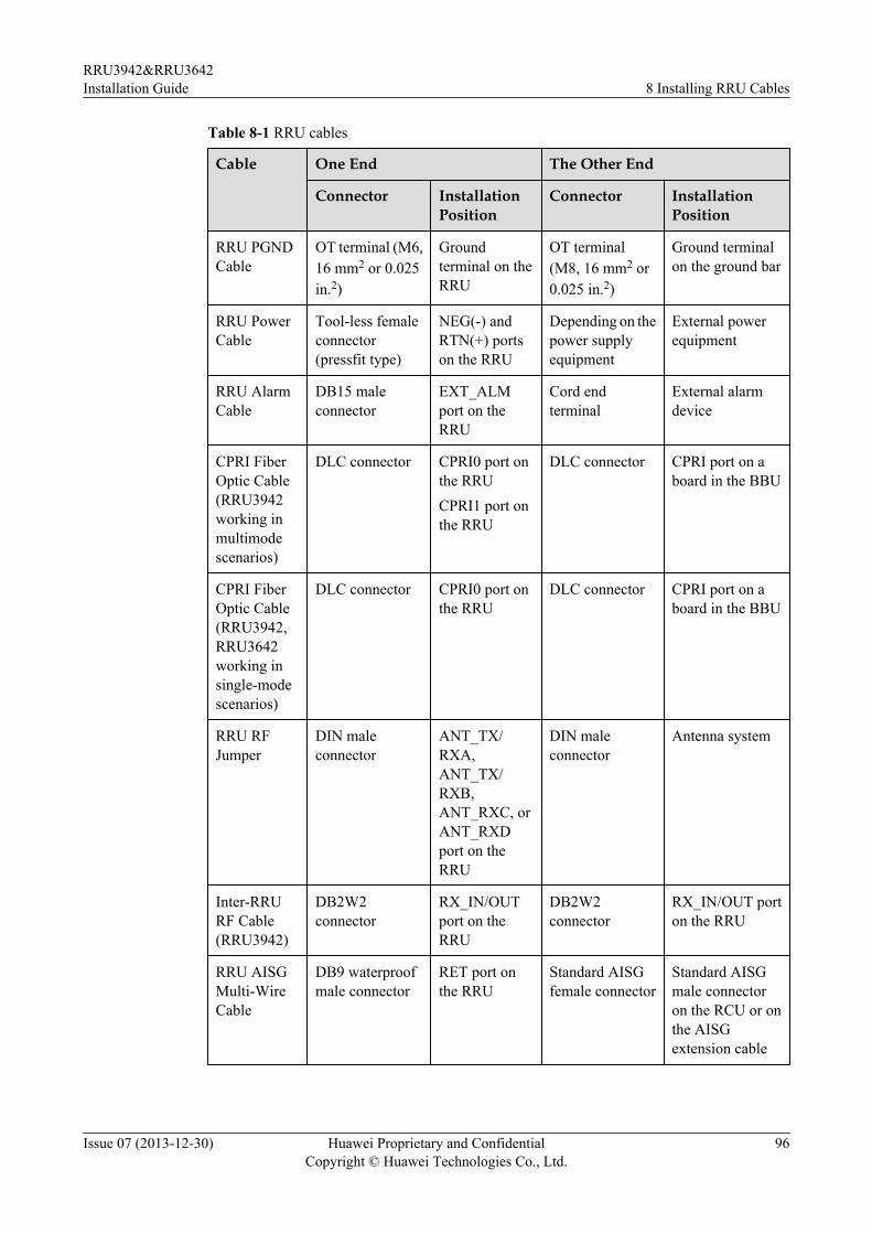
Table 8-1 RRU cables
Cable One End The Other End
Connector InstallationPosition
Connector InstallationPosition
RRU PGNDCable
OT terminal (M6,16 mm2 or 0.025in.2)
Groundterminal on theRRU
OT terminal(M8, 16 mm2 or0.025 in.2)
Ground terminalon the ground bar
RRU PowerCable
Tool-less femaleconnector(pressfit type)
NEG(-) andRTN(+) portson the RRU
Depending on thepower supplyequipment
External powerequipment
RRU AlarmCable
DB15 maleconnector
EXT_ALMport on theRRU
Cord endterminal
External alarmdevice
CPRI FiberOptic Cable(RRU3942working inmultimodescenarios)
DLC connector CPRI0 port onthe RRUCPRI1 port onthe RRU
DLC connector CPRI port on aboard in the BBU
CPRI FiberOptic Cable(RRU3942,RRU3642working insingle-modescenarios)
DLC connector CPRI0 port onthe RRU
DLC connector CPRI port on aboard in the BBU
RRU RFJumper
DIN maleconnector
ANT_TX/RXA,ANT_TX/RXB,ANT_RXC, orANT_RXDport on theRRU
DIN maleconnector
Antenna system
Inter-RRURF Cable(RRU3942)
DB2W2connector
RX_IN/OUTport on theRRU
DB2W2connector
RX_IN/OUT porton the RRU
RRU AISGMulti-WireCable
DB9 waterproofmale connector
RET port onthe RRU
Standard AISGfemale connector
Standard AISGmale connectoron the RCU or onthe AISGextension cable
RRU3942&RRU3642Installation Guide 8 Installing RRU Cables
Issue 07 (2013-12-30) Huawei Proprietary and ConfidentialCopyright © Huawei Technologies Co., Ltd.
96
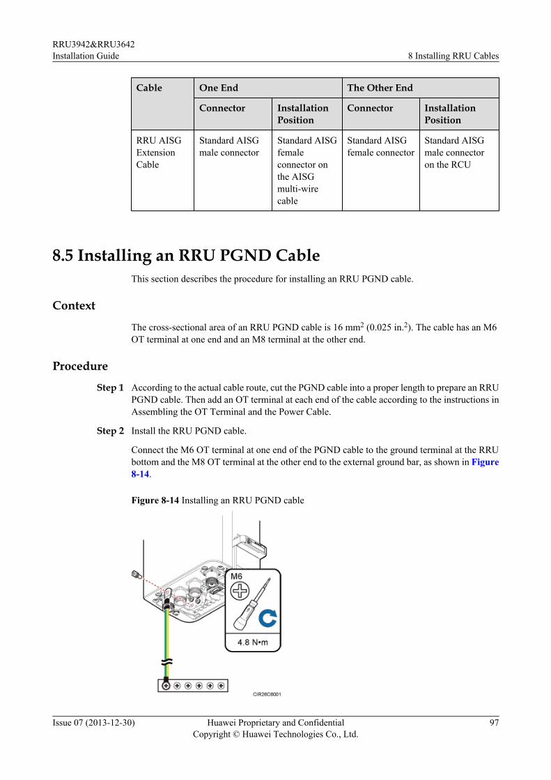
Cable One End The Other End
Connector InstallationPosition
Connector InstallationPosition
RRU AISGExtensionCable
Standard AISGmale connector
Standard AISGfemaleconnector onthe AISGmulti-wirecable
Standard AISGfemale connector
Standard AISGmale connectoron the RCU
8.5 Installing an RRU PGND CableThis section describes the procedure for installing an RRU PGND cable.
Context
The cross-sectional area of an RRU PGND cable is 16 mm2 (0.025 in.2). The cable has an M6OT terminal at one end and an M8 terminal at the other end.
Procedure
Step 1 According to the actual cable route, cut the PGND cable into a proper length to prepare an RRUPGND cable. Then add an OT terminal at each end of the cable according to the instructions inAssembling the OT Terminal and the Power Cable.
Step 2 Install the RRU PGND cable.
Connect the M6 OT terminal at one end of the PGND cable to the ground terminal at the RRUbottom and the M8 OT terminal at the other end to the external ground bar, as shown in Figure8-14.
Figure 8-14 Installing an RRU PGND cable
RRU3942&RRU3642Installation Guide 8 Installing RRU Cables
Issue 07 (2013-12-30) Huawei Proprietary and ConfidentialCopyright © Huawei Technologies Co., Ltd.
97
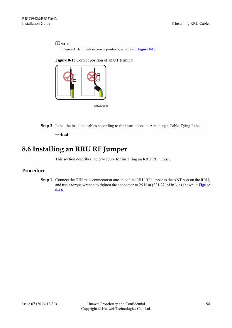
NOTE
Crimp OT terminals in correct positions, as shown in Figure 8-15.
Figure 8-15 Correct position of an OT terminal
Step 3 Label the installed cables according to the instructions in Attaching a Cable-Tying Label.
----End
8.6 Installing an RRU RF JumperThis section describes the procedure for installing an RRU RF jumper.
Procedure
Step 1 Connect the DIN male connector at one end of the RRU RF jumper to the ANT port on the RRU,and use a torque wrench to tighten the connector to 25 N·m (221.27 lbf·in.), as shown in Figure8-16.
RRU3942&RRU3642Installation Guide 8 Installing RRU Cables
Issue 07 (2013-12-30) Huawei Proprietary and ConfidentialCopyright © Huawei Technologies Co., Ltd.
98
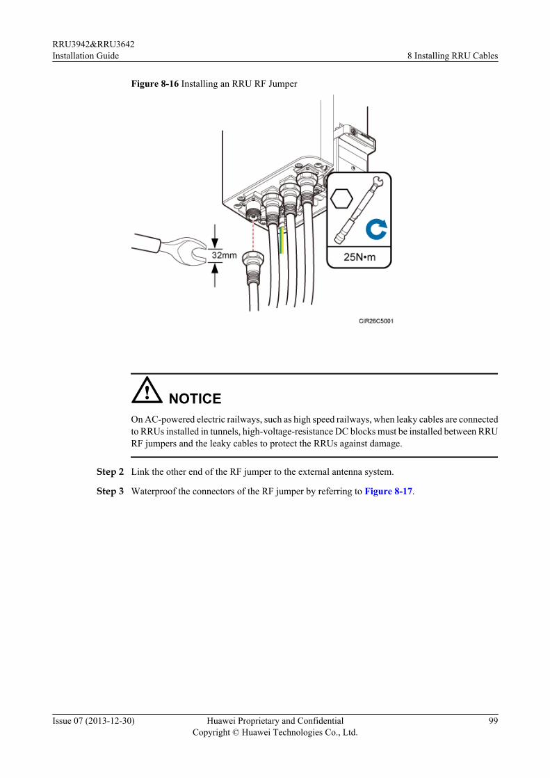
Figure 8-16 Installing an RRU RF Jumper
NOTICEOn AC-powered electric railways, such as high speed railways, when leaky cables are connectedto RRUs installed in tunnels, high-voltage-resistance DC blocks must be installed between RRURF jumpers and the leaky cables to protect the RRUs against damage.
Step 2 Link the other end of the RF jumper to the external antenna system.
Step 3 Waterproof the connectors of the RF jumper by referring to Figure 8-17.
RRU3942&RRU3642Installation Guide 8 Installing RRU Cables
Issue 07 (2013-12-30) Huawei Proprietary and ConfidentialCopyright © Huawei Technologies Co., Ltd.
99
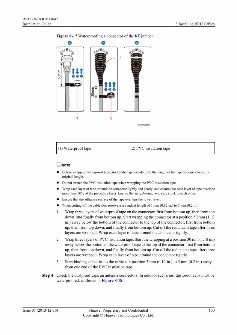
Figure 8-17 Waterproofing a connector of the RF jumper
(1) Waterproof tape (2) PVC insulation tape
NOTE
l Before wrapping waterproof tape, stretch the tape evenly until the length of the tape becomes twice itsoriginal length.
l Do not stretch the PVC insulation tape when wrapping the PVC insulation tape.
l Wrap each layer of tape around the connector tightly and neatly, and ensure that each layer of tape overlapsmore than 50% of the preceding layer. Ensure that neighboring layers are stuck to each other.
l Ensure that the adhesive surface of the tape overlaps the lower layer.
l When cutting off the cable ties, reserve a redundant length of 3 mm (0.12 in.) to 5 mm (0.2 in.).
1. Wrap three layers of waterproof tape on the connector, first from bottom up, then from topdown, and finally from bottom up. Start wrapping the connector at a position 50 mm (1.97in.) away below the bottom of the connector to the top of the connector, first from bottomup, then from top down, and finally from bottom up. Cut off the redundant tape after threelayers are wrapped. Wrap each layer of tape around the connector tightly.
2. Wrap three layers of PVC insulation tape. Start the wrapping at a position 30 mm (1.18 in.)away below the bottom of the waterproof tape to the top of the connector, first from bottomup, then from top down, and finally from bottom up. Cut off the redundant tape after threelayers are wrapped. Wrap each layer of tape around the connector tightly.
3. Start binding cable ties to the cable at a position 3 mm (0.12 in.) to 5 mm (0.2 in.) awayfrom one end of the PVC insulation tape.
Step 4 Check the dustproof caps on antenna connectors. In outdoor scenarios, dustproof caps must bewaterproofed, as shown in Figure 8-18.
RRU3942&RRU3642Installation Guide 8 Installing RRU Cables
Issue 07 (2013-12-30) Huawei Proprietary and ConfidentialCopyright © Huawei Technologies Co., Ltd.
100
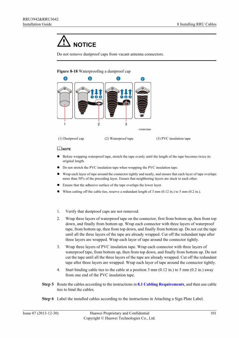
NOTICEDo not remove dustproof caps from vacant antenna connectors.
Figure 8-18 Waterproofing a dustproof cap
(1) Dustproof cap (2) Waterproof tape (3) PVC insulation tape
NOTE
l Before wrapping waterproof tape, stretch the tape evenly until the length of the tape becomes twice itsoriginal length.
l Do not stretch the PVC insulation tape when wrapping the PVC insulation tape.
l Wrap each layer of tape around the connector tightly and neatly, and ensure that each layer of tape overlapsmore than 50% of the preceding layer. Ensure that neighboring layers are stuck to each other.
l Ensure that the adhesive surface of the tape overlaps the lower layer.
l When cutting off the cable ties, reserve a redundant length of 3 mm (0.12 in.) to 5 mm (0.2 in.).
1. Verify that dustproof caps are not removed.
2. Wrap three layers of waterproof tape on the connector, first from bottom up, then from topdown, and finally from bottom up. Wrap each connector with three layers of waterprooftape, from bottom up, then from top down, and finally from bottom up. Do not cut the tapeuntil all the three layers of the tape are already wrapped. Cut off the redundant tape afterthree layers are wrapped. Wrap each layer of tape around the connector tightly.
3. Wrap three layers of PVC insulation tape. Wrap each connector with three layers ofwaterproof tape, from bottom up, then from top down, and finally from bottom up. Do notcut the tape until all the three layers of the tape are already wrapped. Cut off the redundanttape after three layers are wrapped. Wrap each layer of tape around the connector tightly.
4. Start binding cable ties to the cable at a position 3 mm (0.12 in.) to 5 mm (0.2 in.) awayfrom one end of the PVC insulation tape.
Step 5 Route the cables according to the instructions in 8.1 Cabling Requirements, and then use cableties to bind the cables.
Step 6 Label the installed cables according to the instructions in Attaching a Sign Plate Label.
RRU3942&RRU3642Installation Guide 8 Installing RRU Cables
Issue 07 (2013-12-30) Huawei Proprietary and ConfidentialCopyright © Huawei Technologies Co., Ltd.
101
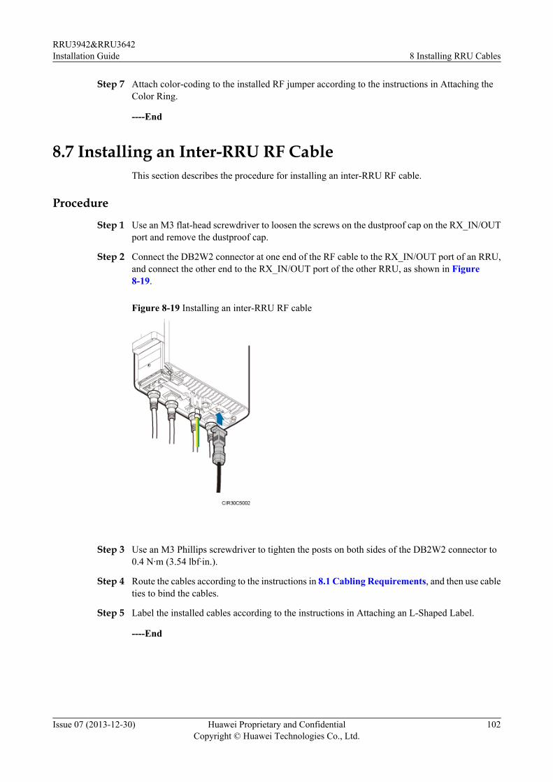
Step 7 Attach color-coding to the installed RF jumper according to the instructions in Attaching theColor Ring.
----End
8.7 Installing an Inter-RRU RF CableThis section describes the procedure for installing an inter-RRU RF cable.
Procedure
Step 1 Use an M3 flat-head screwdriver to loosen the screws on the dustproof cap on the RX_IN/OUTport and remove the dustproof cap.
Step 2 Connect the DB2W2 connector at one end of the RF cable to the RX_IN/OUT port of an RRU,and connect the other end to the RX_IN/OUT port of the other RRU, as shown in Figure8-19.
Figure 8-19 Installing an inter-RRU RF cable
Step 3 Use an M3 Phillips screwdriver to tighten the posts on both sides of the DB2W2 connector to0.4 N·m (3.54 lbf·in.).
Step 4 Route the cables according to the instructions in 8.1 Cabling Requirements, and then use cableties to bind the cables.
Step 5 Label the installed cables according to the instructions in Attaching an L-Shaped Label.
----End
RRU3942&RRU3642Installation Guide 8 Installing RRU Cables
Issue 07 (2013-12-30) Huawei Proprietary and ConfidentialCopyright © Huawei Technologies Co., Ltd.
102
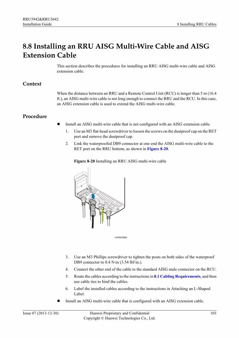
8.8 Installing an RRU AISG Multi-Wire Cable and AISGExtension Cable
This section describes the procedures for installing an RRU AISG multi-wire cable and AISGextension cable.
Context
When the distance between an RRU and a Remote Control Unit (RCU) is longer than 5 m (16.4ft.), an AISG multi-wire cable is not long enough to connect the RRU and the RCU. In this case,an AISG extension cable is used to extend the AISG multi-wire cable.
Procedurel Install an AISG multi-wire cable that is not configured with an AISG extension cable.
1. Use an M3 flat-head screwdriver to loosen the screws on the dustproof cap on the RETport and remove the dustproof cap.
2. Link the waterproofed DB9 connector at one end the AISG multi-wire cable to theRET port on the RRU bottom, as shown in Figure 8-20.
Figure 8-20 Installing an RRU AISG multi-wire cable
3. Use an M3 Phillips screwdriver to tighten the posts on both sides of the waterproofDB9 connector to 0.4 N·m (3.54 lbf·in.).
4. Connect the other end of the cable to the standard AISG male connector on the RCU.
5. Route the cables according to the instructions in 8.1 Cabling Requirements, and thenuse cable ties to bind the cables.
6. Label the installed cables according to the instructions in Attaching an L-ShapedLabel.
l Install an AISG multi-wire cable that is configured with an AISG extension cable.
RRU3942&RRU3642Installation Guide 8 Installing RRU Cables
Issue 07 (2013-12-30) Huawei Proprietary and ConfidentialCopyright © Huawei Technologies Co., Ltd.
103
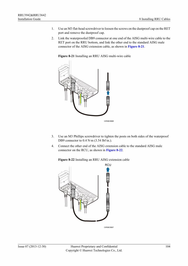
1. Use an M3 flat-head screwdriver to loosen the screws on the dustproof cap on the RETport and remove the dustproof cap.
2. Link the waterproofed DB9 connector at one end of the AISG multi-wire cable to theRET port on the RRU bottom, and link the other end to the standard AISG maleconnector of the AISG extension cable, as shown in Figure 8-21.
Figure 8-21 Installing an RRU AISG multi-wire cable
3. Use an M3 Phillips screwdriver to tighten the posts on both sides of the waterproofDB9 connector to 0.4 N·m (3.54 lbf·in.).
4. Connect the other end of the AISG extension cable to the standard AISG maleconnector on the RCU, as shown in Figure 8-22.
Figure 8-22 Installing an RRU AISG extension cable
RRU3942&RRU3642Installation Guide 8 Installing RRU Cables
Issue 07 (2013-12-30) Huawei Proprietary and ConfidentialCopyright © Huawei Technologies Co., Ltd.
104
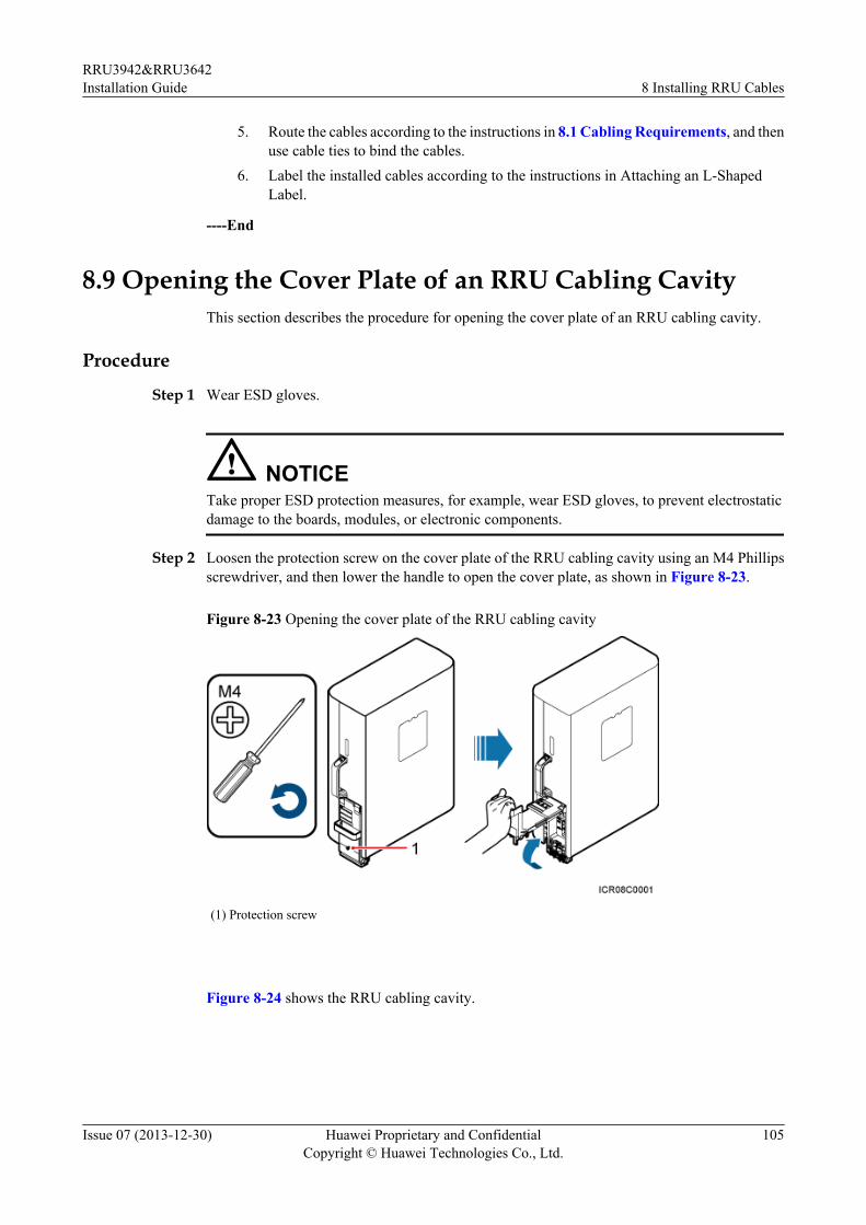
5. Route the cables according to the instructions in 8.1 Cabling Requirements, and thenuse cable ties to bind the cables.
6. Label the installed cables according to the instructions in Attaching an L-ShapedLabel.
----End
8.9 Opening the Cover Plate of an RRU Cabling CavityThis section describes the procedure for opening the cover plate of an RRU cabling cavity.
Procedure
Step 1 Wear ESD gloves.
NOTICETake proper ESD protection measures, for example, wear ESD gloves, to prevent electrostaticdamage to the boards, modules, or electronic components.
Step 2 Loosen the protection screw on the cover plate of the RRU cabling cavity using an M4 Phillipsscrewdriver, and then lower the handle to open the cover plate, as shown in Figure 8-23.
Figure 8-23 Opening the cover plate of the RRU cabling cavity
(1) Protection screw
Figure 8-24 shows the RRU cabling cavity.
RRU3942&RRU3642Installation Guide 8 Installing RRU Cables
Issue 07 (2013-12-30) Huawei Proprietary and ConfidentialCopyright © Huawei Technologies Co., Ltd.
105
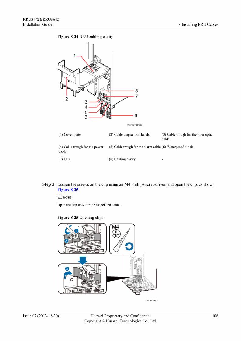
Figure 8-24 RRU cabling cavity
(1) Cover plate (2) Cable diagram on labels (3) Cable trough for the fiber opticcable
(4) Cable trough for the powercable
(5) Cable trough for the alarm cable (6) Waterproof block
(7) Clip (8) Cabling cavity -
Step 3 Loosen the screws on the clip using an M4 Phillips screwdriver, and open the clip, as shownFigure 8-25.
NOTE
Open the clip only for the associated cable.
Figure 8-25 Opening clips
RRU3942&RRU3642Installation Guide 8 Installing RRU Cables
Issue 07 (2013-12-30) Huawei Proprietary and ConfidentialCopyright © Huawei Technologies Co., Ltd.
106
Step 4 Remove the waterproof block.
NOTE
Remove only the waterproof blocks for the cables to be installed.
----End
8.10 Installing an RRU Power CableThis section describes the procedure for installing an RRU power cable.
Prerequisitesl A tool-less female connector (pressfit type) is added to the RRU power cable on the RRU
side. For details, see 11.1 Adding a Tool-Less Female Connector (Pressfit Type) to theRRU Power Cable on the RRU Side.
l A connector or OT terminals are added to the RRU power cable on the power device side.For details, see the DBS3900 Installation Guide.
Context
If a power device provided by the customer is used, the recommended specification of the circuitbreaker on this power device is 15 A to 30 A.
There are three types of RRU power cables in terms of cross-sectional areas: 5.3 mm2 (0.008in.2) (10 AWG) and 8.2 mm2 (0.013 in.2) (8 AWG) complying with North American standardsand 6 mm2 (0.009 in.2) complying with European standards.
Table 8-2 describes the RRU power cable.
Table 8-2 RRU power cable
Cable On the RRUSide
On thePowerDevice Side
PowerDevice
Color
RRUpowercable
Tool-less femaleconnector(pressfit type)
Tool-lessfemaleconnector(pressfit type)
EPU A cable with a black jacket and twowires insidel North American standards: The
RTN(+) wire is black and theRNEG(-) wire is blue.
l European standards: The RTN(+) wire is brown and the RNEG(-) wire is blue.
DCDU-11B
EPC5connector
DCDU-12B
RRU3942&RRU3642Installation Guide 8 Installing RRU Cables
Issue 07 (2013-12-30) Huawei Proprietary and ConfidentialCopyright © Huawei Technologies Co., Ltd.
107
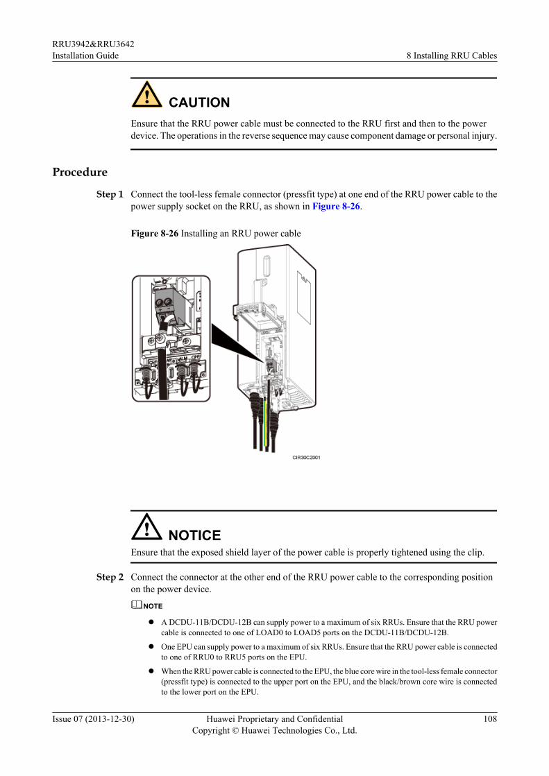
CAUTIONEnsure that the RRU power cable must be connected to the RRU first and then to the powerdevice. The operations in the reverse sequence may cause component damage or personal injury.
Procedure
Step 1 Connect the tool-less female connector (pressfit type) at one end of the RRU power cable to thepower supply socket on the RRU, as shown in Figure 8-26.
Figure 8-26 Installing an RRU power cable
NOTICEEnsure that the exposed shield layer of the power cable is properly tightened using the clip.
Step 2 Connect the connector at the other end of the RRU power cable to the corresponding positionon the power device.
NOTE
l A DCDU-11B/DCDU-12B can supply power to a maximum of six RRUs. Ensure that the RRU powercable is connected to one of LOAD0 to LOAD5 ports on the DCDU-11B/DCDU-12B.
l One EPU can supply power to a maximum of six RRUs. Ensure that the RRU power cable is connectedto one of RRU0 to RRU5 ports on the EPU.
l When the RRU power cable is connected to the EPU, the blue core wire in the tool-less female connector(pressfit type) is connected to the upper port on the EPU, and the black/brown core wire is connectedto the lower port on the EPU.
RRU3942&RRU3642Installation Guide 8 Installing RRU Cables
Issue 07 (2013-12-30) Huawei Proprietary and ConfidentialCopyright © Huawei Technologies Co., Ltd.
108
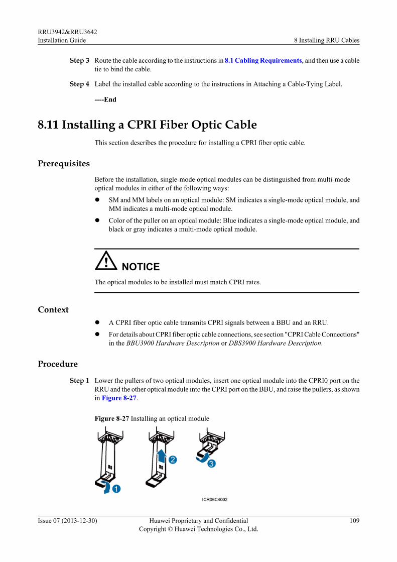
Step 3 Route the cable according to the instructions in 8.1 Cabling Requirements, and then use a cabletie to bind the cable.
Step 4 Label the installed cable according to the instructions in Attaching a Cable-Tying Label.
----End
8.11 Installing a CPRI Fiber Optic CableThis section describes the procedure for installing a CPRI fiber optic cable.
Prerequisites
Before the installation, single-mode optical modules can be distinguished from multi-modeoptical modules in either of the following ways:
l SM and MM labels on an optical module: SM indicates a single-mode optical module, andMM indicates a multi-mode optical module.
l Color of the puller on an optical module: Blue indicates a single-mode optical module, andblack or gray indicates a multi-mode optical module.
NOTICEThe optical modules to be installed must match CPRI rates.
Contextl A CPRI fiber optic cable transmits CPRI signals between a BBU and an RRU.
l For details about CPRI fiber optic cable connections, see section "CPRI Cable Connections"in the BBU3900 Hardware Description or DBS3900 Hardware Description.
Procedure
Step 1 Lower the pullers of two optical modules, insert one optical module into the CPRI0 port on theRRU and the other optical module into the CPRI port on the BBU, and raise the pullers, as shownin Figure 8-27.
Figure 8-27 Installing an optical module
RRU3942&RRU3642Installation Guide 8 Installing RRU Cables
Issue 07 (2013-12-30) Huawei Proprietary and ConfidentialCopyright © Huawei Technologies Co., Ltd.
109
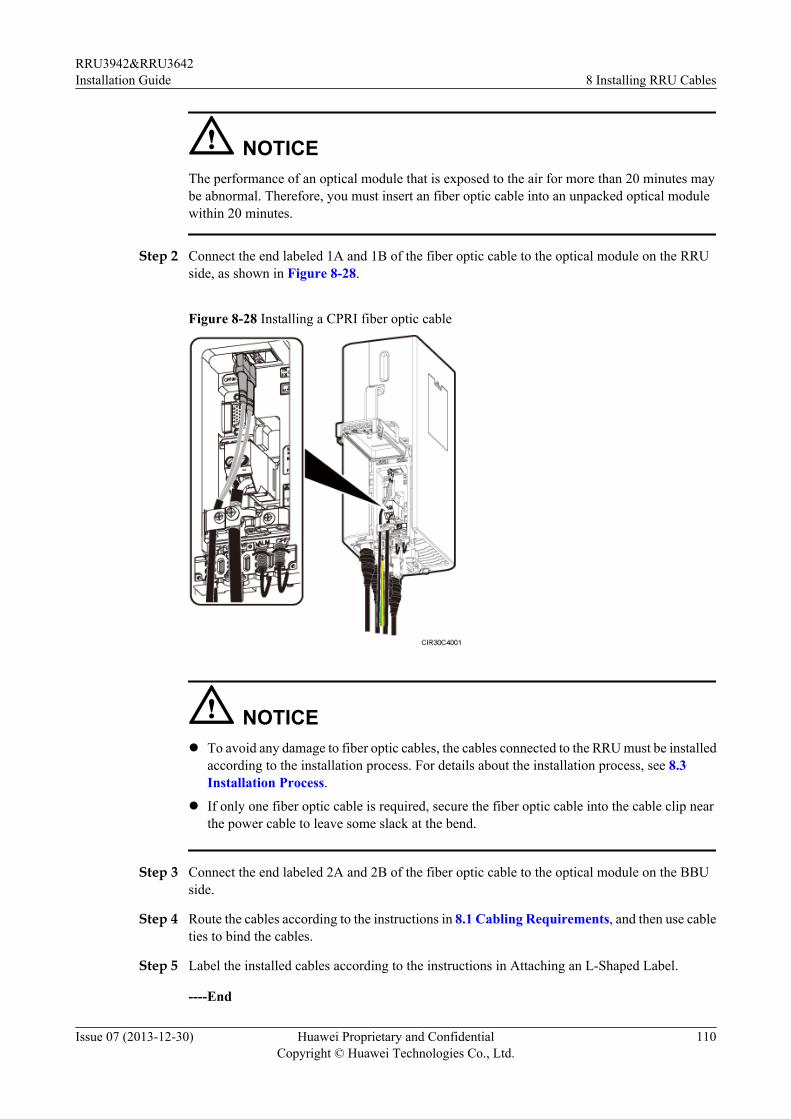
NOTICEThe performance of an optical module that is exposed to the air for more than 20 minutes maybe abnormal. Therefore, you must insert an fiber optic cable into an unpacked optical modulewithin 20 minutes.
Step 2 Connect the end labeled 1A and 1B of the fiber optic cable to the optical module on the RRUside, as shown in Figure 8-28.
Figure 8-28 Installing a CPRI fiber optic cable
NOTICEl To avoid any damage to fiber optic cables, the cables connected to the RRU must be installed
according to the installation process. For details about the installation process, see 8.3Installation Process.
l If only one fiber optic cable is required, secure the fiber optic cable into the cable clip nearthe power cable to leave some slack at the bend.
Step 3 Connect the end labeled 2A and 2B of the fiber optic cable to the optical module on the BBUside.
Step 4 Route the cables according to the instructions in 8.1 Cabling Requirements, and then use cableties to bind the cables.
Step 5 Label the installed cables according to the instructions in Attaching an L-Shaped Label.
----End
RRU3942&RRU3642Installation Guide 8 Installing RRU Cables
Issue 07 (2013-12-30) Huawei Proprietary and ConfidentialCopyright © Huawei Technologies Co., Ltd.
110
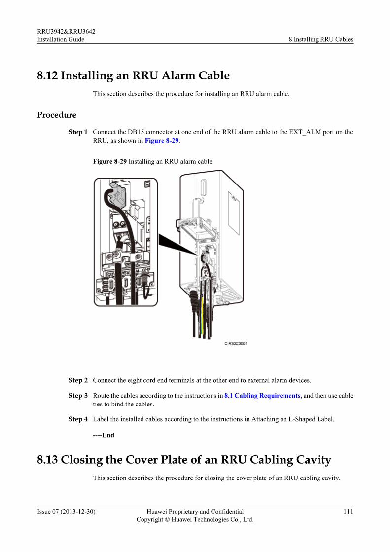
8.12 Installing an RRU Alarm CableThis section describes the procedure for installing an RRU alarm cable.
Procedure
Step 1 Connect the DB15 connector at one end of the RRU alarm cable to the EXT_ALM port on theRRU, as shown in Figure 8-29.
Figure 8-29 Installing an RRU alarm cable
Step 2 Connect the eight cord end terminals at the other end to external alarm devices.
Step 3 Route the cables according to the instructions in 8.1 Cabling Requirements, and then use cableties to bind the cables.
Step 4 Label the installed cables according to the instructions in Attaching an L-Shaped Label.
----End
8.13 Closing the Cover Plate of an RRU Cabling CavityThis section describes the procedure for closing the cover plate of an RRU cabling cavity.
RRU3942&RRU3642Installation Guide 8 Installing RRU Cables
Issue 07 (2013-12-30) Huawei Proprietary and ConfidentialCopyright © Huawei Technologies Co., Ltd.
111
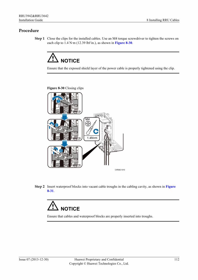
Procedure
Step 1 Close the clips for the installed cables. Use an M4 torque screwdriver to tighten the screws oneach clip to 1.4 N·m (12.39 lbf·in.), as shown in Figure 8-30.
NOTICEEnsure that the exposed shield layer of the power cable is properly tightened using the clip.
Figure 8-30 Closing clips
Step 2 Insert waterproof blocks into vacant cable troughs in the cabling cavity, as shown in Figure8-31.
NOTICEEnsure that cables and waterproof blocks are properly inserted into troughs.
RRU3942&RRU3642Installation Guide 8 Installing RRU Cables
Issue 07 (2013-12-30) Huawei Proprietary and ConfidentialCopyright © Huawei Technologies Co., Ltd.
112
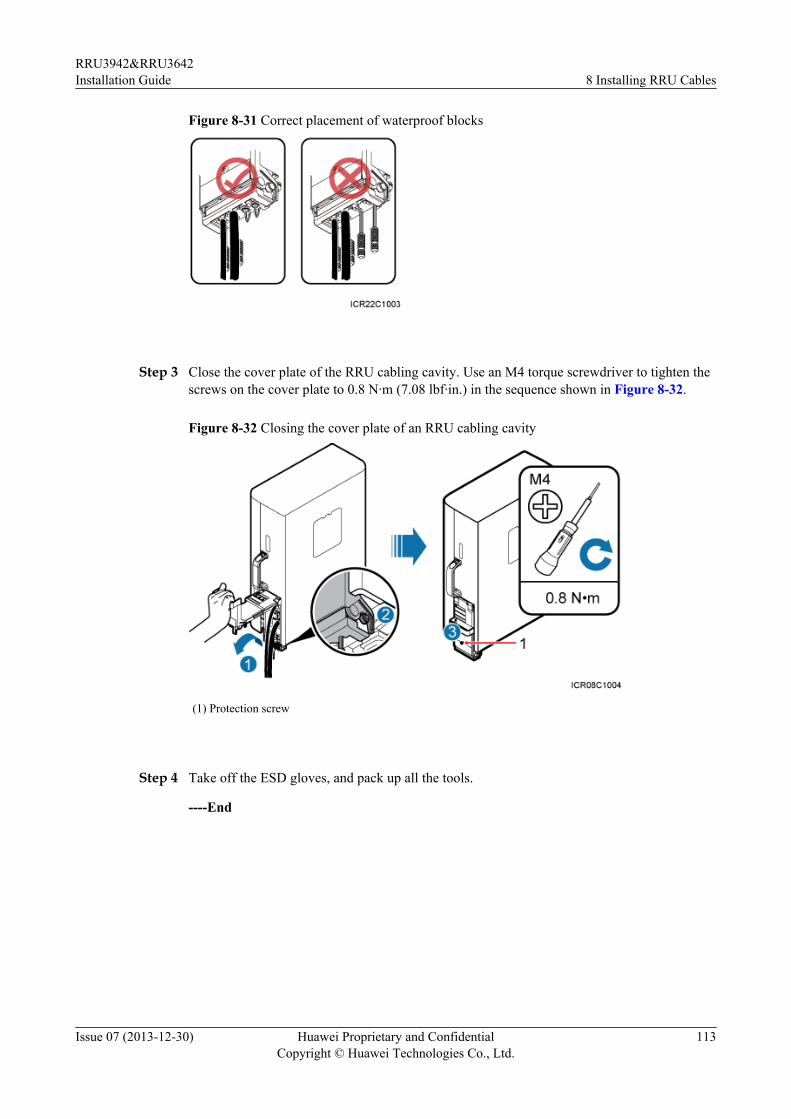
Figure 8-31 Correct placement of waterproof blocks
Step 3 Close the cover plate of the RRU cabling cavity. Use an M4 torque screwdriver to tighten thescrews on the cover plate to 0.8 N·m (7.08 lbf·in.) in the sequence shown in Figure 8-32.
Figure 8-32 Closing the cover plate of an RRU cabling cavity
(1) Protection screw
Step 4 Take off the ESD gloves, and pack up all the tools.
----End
RRU3942&RRU3642Installation Guide 8 Installing RRU Cables
Issue 07 (2013-12-30) Huawei Proprietary and ConfidentialCopyright © Huawei Technologies Co., Ltd.
113
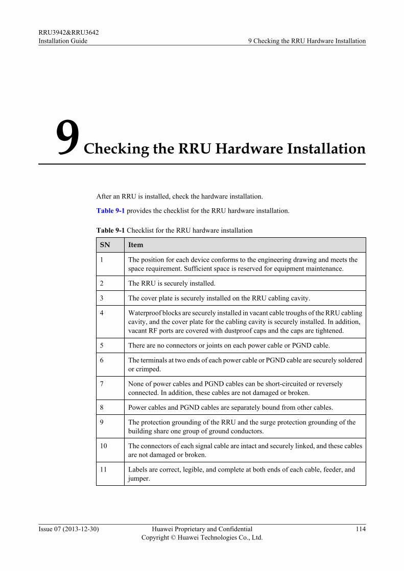
9 Checking the RRU Hardware Installation
After an RRU is installed, check the hardware installation.
Table 9-1 provides the checklist for the RRU hardware installation.
Table 9-1 Checklist for the RRU hardware installation
SN Item
1 The position for each device conforms to the engineering drawing and meets thespace requirement. Sufficient space is reserved for equipment maintenance.
2 The RRU is securely installed.
3 The cover plate is securely installed on the RRU cabling cavity.
4 Waterproof blocks are securely installed in vacant cable troughs of the RRU cablingcavity, and the cover plate for the cabling cavity is securely installed. In addition,vacant RF ports are covered with dustproof caps and the caps are tightened.
5 There are no connectors or joints on each power cable or PGND cable.
6 The terminals at two ends of each power cable or PGND cable are securely solderedor crimped.
7 None of power cables and PGND cables can be short-circuited or reverselyconnected. In addition, these cables are not damaged or broken.
8 Power cables and PGND cables are separately bound from other cables.
9 The protection grounding of the RRU and the surge protection grounding of thebuilding share one group of ground conductors.
10 The connectors of each signal cable are intact and securely linked, and these cablesare not damaged or broken.
11 Labels are correct, legible, and complete at both ends of each cable, feeder, andjumper.
RRU3942&RRU3642Installation Guide 9 Checking the RRU Hardware Installation
Issue 07 (2013-12-30) Huawei Proprietary and ConfidentialCopyright © Huawei Technologies Co., Ltd.
114
10 Powering On an RRU
After all the devices are installed, check the power-on status of an RRU.
NOTICEAfter you unpack an RRU, you must power on it within 24 hours. If you power off the RRU formaintenance, you must restore power to the RRU within 24 hours.
Figure 10-1 shows the RRU power-on check process.
NOTE
For details about how to power on an RRU, see Powering On an RRU. For details about how to power offan RRU, see section "Powering-Off the RRU" in RRU Maintenance Guide.
RRU3942&RRU3642Installation Guide 10 Powering On an RRU
Issue 07 (2013-12-30) Huawei Proprietary and ConfidentialCopyright © Huawei Technologies Co., Ltd.
115

Figure 10-1 RRU power-on check process
(a) The normal input voltage of an RRU is -48 V DC. The voltage of the external power supply should rangefrom -36 V DC to -57 V DC.
(b) The RUN indicator on the RRU is on for 1s and off for 1s. The ALM indicator is steady off.
RRU3942&RRU3642Installation Guide 10 Powering On an RRU
Issue 07 (2013-12-30) Huawei Proprietary and ConfidentialCopyright © Huawei Technologies Co., Ltd.
116
11 Appendix
About This Chapter
This section describes the procedure for adding an easy power receptacle (pressfit type)connector.
11.1 Adding a Tool-Less Female Connector (Pressfit Type) to the RRU Power Cable on theRRU SideThis section describes the procedure for adding a tool-less female connector (pressfit type) tothe RRU power cable on the RRU side.
RRU3942&RRU3642Installation Guide 11 Appendix
Issue 07 (2013-12-30) Huawei Proprietary and ConfidentialCopyright © Huawei Technologies Co., Ltd.
117
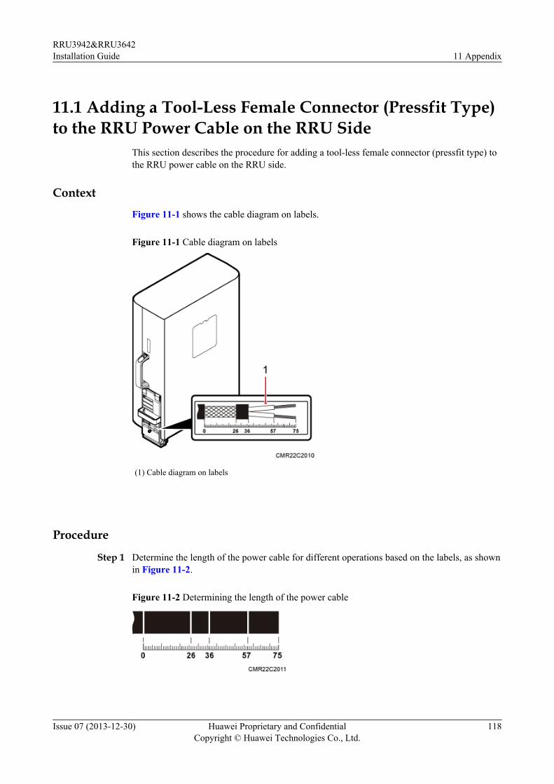
11.1 Adding a Tool-Less Female Connector (Pressfit Type)to the RRU Power Cable on the RRU Side
This section describes the procedure for adding a tool-less female connector (pressfit type) tothe RRU power cable on the RRU side.
Context
Figure 11-1 shows the cable diagram on labels.
Figure 11-1 Cable diagram on labels
(1) Cable diagram on labels
Procedure
Step 1 Determine the length of the power cable for different operations based on the labels, as shownin Figure 11-2.
Figure 11-2 Determining the length of the power cable
RRU3942&RRU3642Installation Guide 11 Appendix
Issue 07 (2013-12-30) Huawei Proprietary and ConfidentialCopyright © Huawei Technologies Co., Ltd.
118
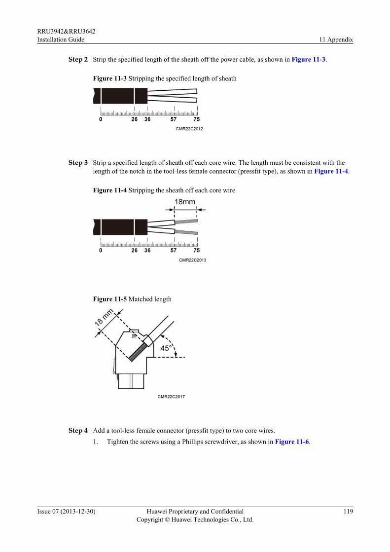
Step 2 Strip the specified length of the sheath off the power cable, as shown in Figure 11-3.
Figure 11-3 Stripping the specified length of sheath
Step 3 Strip a specified length of sheath off each core wire. The length must be consistent with thelength of the notch in the tool-less female connector (pressfit type), as shown in Figure 11-4.
Figure 11-4 Stripping the sheath off each core wire
Figure 11-5 Matched length
Step 4 Add a tool-less female connector (pressfit type) to two core wires.1. Tighten the screws using a Phillips screwdriver, as shown in Figure 11-6.
RRU3942&RRU3642Installation Guide 11 Appendix
Issue 07 (2013-12-30) Huawei Proprietary and ConfidentialCopyright © Huawei Technologies Co., Ltd.
119
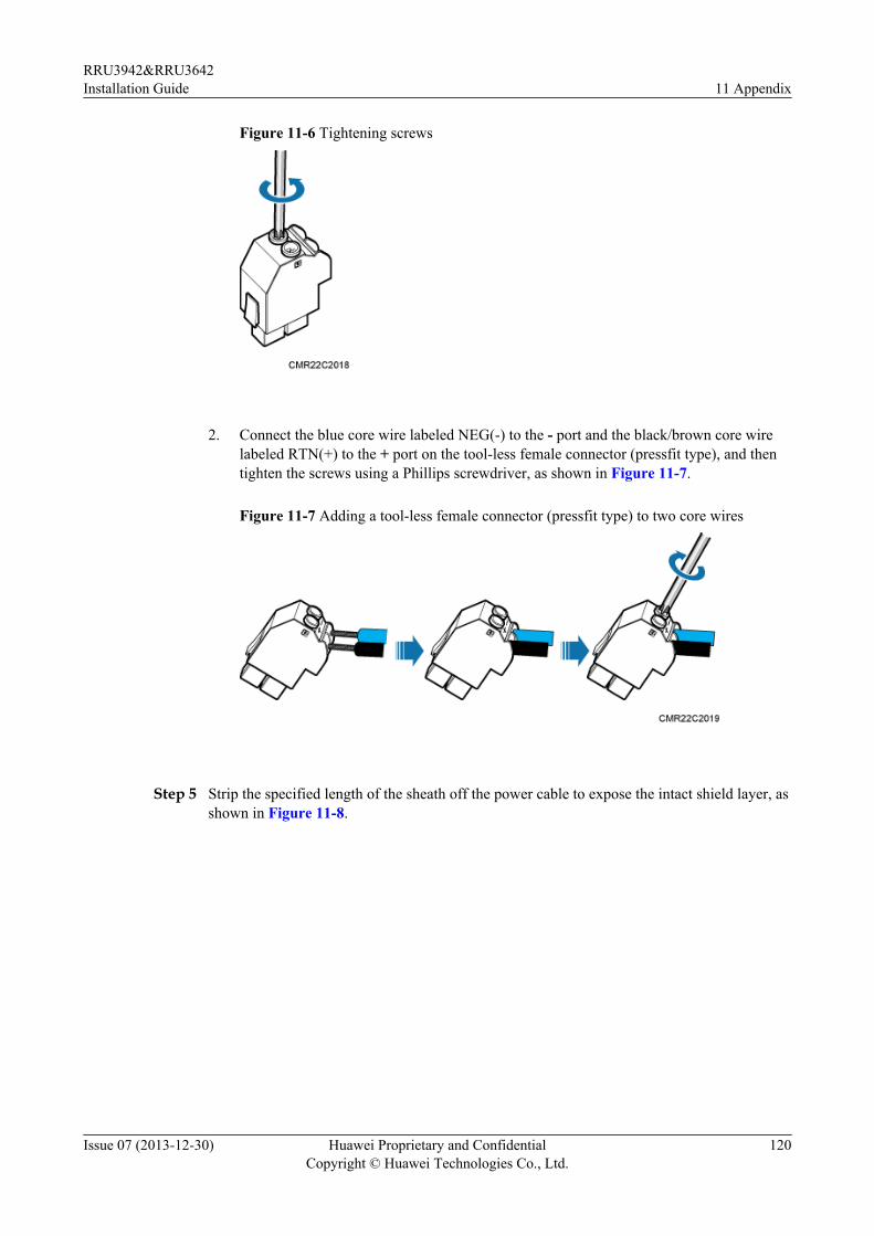
Figure 11-6 Tightening screws
2. Connect the blue core wire labeled NEG(-) to the - port and the black/brown core wire
labeled RTN(+) to the + port on the tool-less female connector (pressfit type), and thentighten the screws using a Phillips screwdriver, as shown in Figure 11-7.
Figure 11-7 Adding a tool-less female connector (pressfit type) to two core wires
Step 5 Strip the specified length of the sheath off the power cable to expose the intact shield layer, asshown in Figure 11-8.
RRU3942&RRU3642Installation Guide 11 Appendix
Issue 07 (2013-12-30) Huawei Proprietary and ConfidentialCopyright © Huawei Technologies Co., Ltd.
120
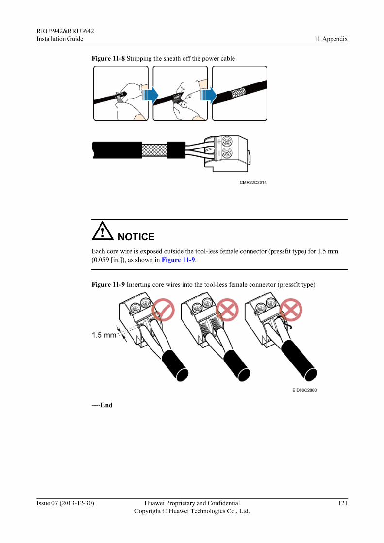
Figure 11-8 Stripping the sheath off the power cable
NOTICEEach core wire is exposed outside the tool-less female connector (pressfit type) for 1.5 mm(0.059 [in.]), as shown in Figure 11-9.
Figure 11-9 Inserting core wires into the tool-less female connector (pressfit type)
----End
RRU3942&RRU3642Installation Guide 11 Appendix
Issue 07 (2013-12-30) Huawei Proprietary and ConfidentialCopyright © Huawei Technologies Co., Ltd.
121