installation guide - advantage air to the connected home installation guide v1.1 installation guide...
TRANSCRIPT
Welcome to the Connected Home
Installation Guide
V1.1
Installation Guide V1.1
MyLights Installation Guide
Contents1 - ELECTRICAL SAFETY 1
2 - SYSTEM OVERVIEW 2
3 - LM OVERVIEW 3
4 - LIGHT ID (LID) CONFIG. 4
5 - LED SPECIFICATIONS 5
6 - RELAY MODULE (RM) 6
7 - RELAYS 7
8 - MODULE FEATURES (LM / RM) 8
9 - PLANNING 9
10 - WIRING LOOKUP TABLE 10
11 - WIRING 11
12 - POWER POINTS 22
13 - CUT OUTS 22
14 - CABLING 23
15 - INSTALLATION 24
16 - SETUP WIZARD 25
Installation Guide V1.1 1 Installation Guide V1.1 2
MyLights must be installed and/or used in accordance with your current local electrical codes & regulations.
If you are unsure about any part of this installation guide contact a licensed electrician before proceeding.
Some steps of the installation process are required to be completed only by a licensed electrician; these steps are marked with this symbol.
MyLights conforms to the following safety standards:
AS/NZS 61347.1:2002AS/NZS 61347-2-13:2013AS/NZS 60598.1:2013AS/NZS 60598.2.2:2016
While MyLights is primarily an Extra Low Voltage (ELV) system installations may have a mix of 240V and ELV wiring and switches.Always ensure the MAIN POWER breaker is OFF before connecting / configuring or modifying MyLights.
The MyLights system runs at extra low voltages (ELV). Mega (aka megger) tests do not apply. The MyLights PS-48s and the CB PSU-ACDC MUST be physically unplugged from their GPOs before Mega testing an electrical install.
Please also note that all MyLights wall switches that connect to the LM are not part of the 240V electrical install. These are ELV, and MUST not be subject to any Mega testing.
1 - ELECTRICAL SAFETY 2 - SYSTEM OVERVIEW
Scenes SetUpGroupsFavourites Help
Master
FavouritesMaster
All On All Off
Entry
WIR
All On All Off
Ensuite
All On All Off
Hall Way
All On All Off
Rocco Jade Bathroom
Guest Kitchen Dining Living
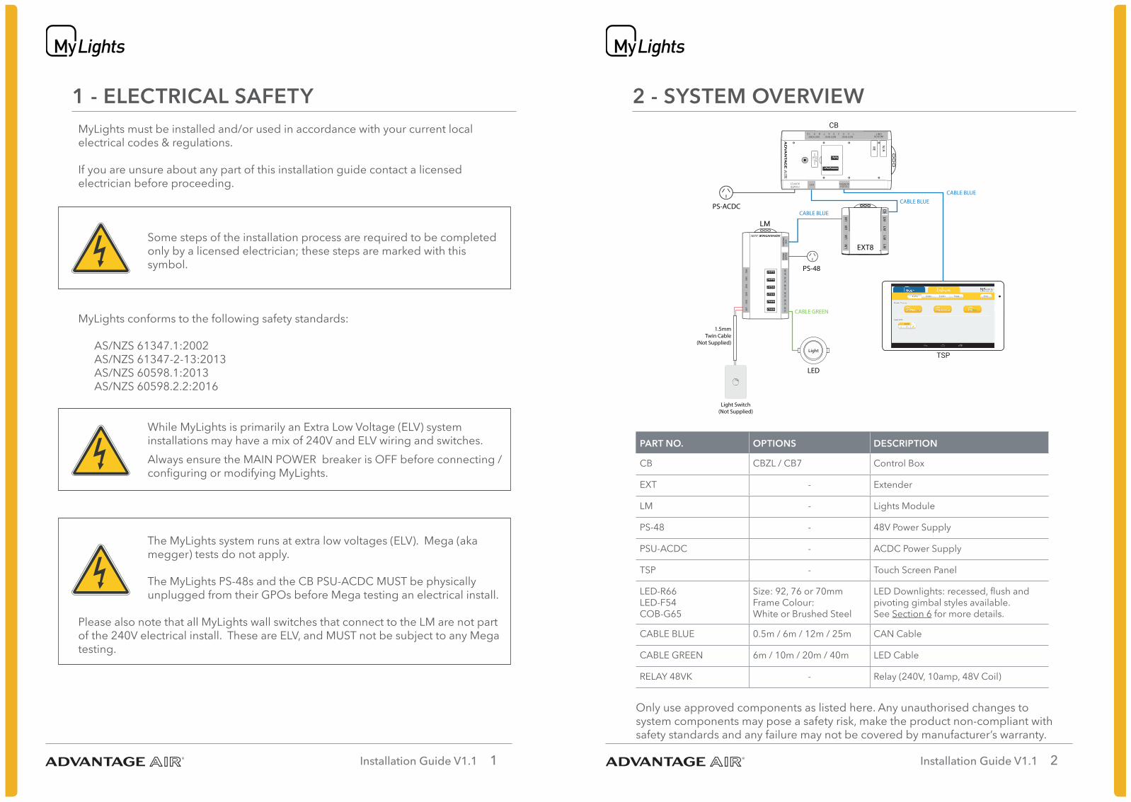
PS-48
CABLE BLUE
CABLE GREEN
PS-ACDC
Light Switch(Not Supplied)
Light
EXT8CB
1.5mmTwin Cable
(Not Supplied)
LED
CABLE BLUE
CABLE BLUE
PART NO. OPTIONS DESCRIPTION
CB CBZL / CB7 Control Box
EXT - Extender
LM - Lights Module
PS-48 - 48V Power Supply
PSU-ACDC - ACDC Power Supply
TSP - Touch Screen Panel
LED-R66LED-F54COB-G65
Size: 92, 76 or 70mmFrame Colour: White or Brushed Steel
LED Downlights: recessed, flush and pivoting gimbal styles available.See Section 6 for more details.
CABLE BLUE 0.5m / 6m / 12m / 25m CAN Cable
CABLE GREEN 6m / 10m / 20m / 40m LED Cable
RELAY 48VK - Relay (240V, 10amp, 48V Coil)
Only use approved components as listed here. Any unauthorised changes to system components may pose a safety risk, make the product non-compliant with safety standards and any failure may not be covered by manufacturer’s warranty.
Installation Guide V1.1 3 Installation Guide V1.1 4
3 - LM OVERVIEW
56
14
32
ON
56
14
32
ON
56
14
32
ON
56
14
32
ON
56
14
32
ON
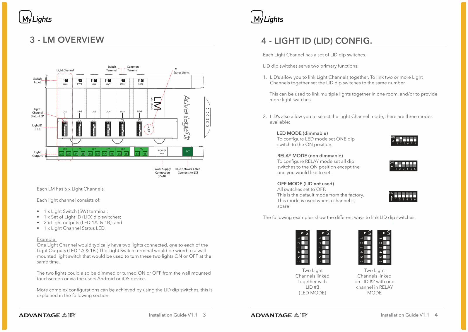
LID1 LID2 LID3 LID4 LID5 LID6
LMLights Module
SW6SW5SW4SW3SW2SW1S C S C S C S C S C S C
1A 1B 2A 2B 3A 3B 4A 4B 5A 5B 6A 6B
LED LED LED LED LED LED POWERPS-48
EXT
56
14
32
ON
Light Channel
Light ID (LID)
Light Channel
Status LED
SwitchInput
LightOutputs
Power Supply Connection
(PS-48)
SwitchTerminal
CommonTerminal
Blue Network Cable Connects to EXT
LM Status Lights
Each LM has 6 x Light Channels.
Each light channel consists of:
• 1 x Light Switch (SW) terminal;• 1 x Set of Light ID (LID) dip switches;• 2 x Light outputs (LED 1A & 1B); and• 1 x Light Channel Status LED.
Example:One Light Channel would typically have two lights connected, one to each of the Light Outputs (LED 1A & 1B.) The Light Switch terminal would be wired to a wall mounted light switch that would be used to turn these two lights ON or OFF at the same time.
The two lights could also be dimmed or turned ON or OFF from the wall mounted touchscreen or via the users Android or iOS device.
More complex configurations can be achieved by using the LID dip switches, this is explained in the following section.
4 - LIGHT ID (LID) CONFIG.
Two Light Channels linked
together with LID #3
(LED MODE)
Two Light Channels linked
on LID #2 with one channel in RELAY
MODE
56
14
32
ON
56
14
32
ON
56
14
32
ON
56
14
32
ON
Each Light Channel has a set of LID dip switches. LID dip switches serve two primary functions:
1. LID’s allow you to link Light Channels together. To link two or more Light Channels together set the LID dip switches to the same number.
This can be used to link multiple lights together in one room, and/or to provide more light switches.
2. LID’s also allow you to select the Light Channel mode, there are three modes available: LED MODE (dimmable)
To configure LED mode set ONE dip switch to the ON position. RELAY MODE (non dimmable)To configure RELAY mode set all dip switches to the ON position except the one you would like to set.
OFF MODE (LID not used)All switches set to OFF.This is the default mode from the factory.This mode is used when a channel is spare
The following examples show the different ways to link LID dip switches.
5 61 432
ON
5 61 432
ON
5 61 432
ON
Installation Guide V1.1 5 Installation Guide V1.1 6
PART NO. DESCRIPTIONCUTOUT
SIZEIP
BEAM /
GIMBAL
ANGLE
TRIM
OPTIONSCOLOUR
LED-R66-92
Recessed, colour change LED downlight
(10W)
92mm IP66 90º
White (W)or
Brushed Steel (S)
Warm White,Natural White,Cool White.*LED-R66-70
Recessed, colour change LED downlight
(10W)
70mm IP66 90º
LED-F54-92
Flush, colour change LED downlight
(10W)
92mm IP54 90º
LED-F54-70
Flush, colour change LED downlight
(10W)
70mm IP54 90º Warm White (WW),
Natural White (NW),
Cool White (CW).**
COB-G65-76Gimbal LED downlight
(10W)76mm IP65 90º / ±30º
COB-G65-70Gimbal LED downlight
(5W)70mm IP65 90º / ±30º
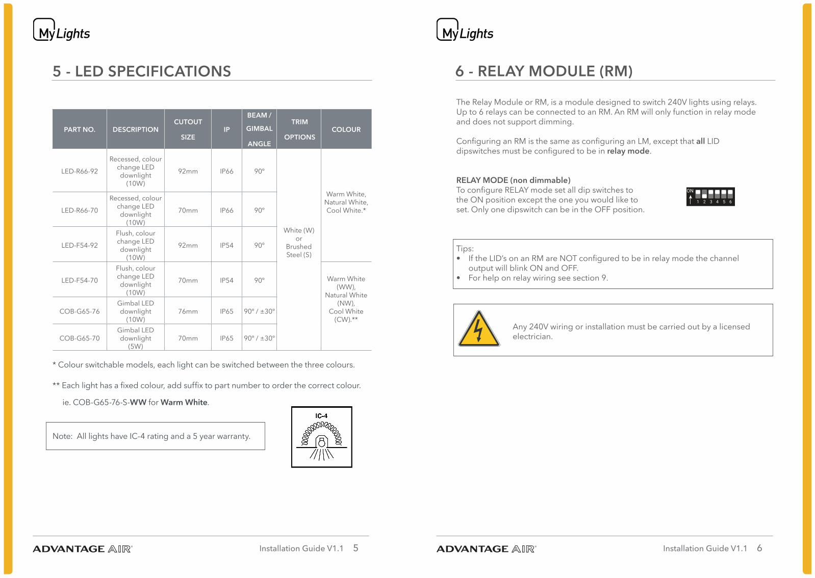
* Colour switchable models, each light can be switched between the three colours.
** Each light has a fixed colour, add suffix to part number to order the correct colour.
ie. COB-G65-76-S-WW for Warm White.
Note: All lights have IC-4 rating and a 5 year warranty.
5 - LED SPECIFICATIONS 6 - RELAY MODULE (RM)
The Relay Module or RM, is a module designed to switch 240V lights using relays. Up to 6 relays can be connected to an RM. An RM will only function in relay mode and does not support dimming.
Configuring an RM is the same as configuring an LM, except that all LID dipswitches must be configured to be in relay mode.
RELAY MODE (non dimmable)To configure RELAY mode set all dip switches to the ON position except the one you would like to set. Only one dipswitch can be in the OFF position.
Tips: • If the LID’s on an RM are NOT configured to be in relay mode the channel
output will blink ON and OFF.• For help on relay wiring see section 9.
Any 240V wiring or installation must be carried out by a licensed electrician.
5 61 432
ON
Installation Guide V1.1 7 Installation Guide V1.1 8
7 - RELAYS
TO MAINS
NOT SUPPLIED
NEUTRAL
BP CONNECTOR
ACTIVE ACTIVE
NEUTRAL
TO LIGHTTO LM / RM
8
5
6 4
3 1277
8
5 3
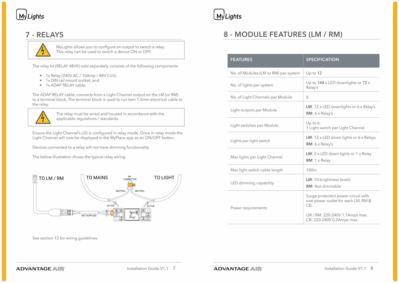
MyLights allows you to configure an output to switch a relay.This relay can be used to switch a device ON or OFF.
The relay kit (RELAY 48VK) sold separately, consists of the following components:
• 1x Relay (240V AC / 10Amp / 48V Coil);• 1x DIN rail mount socket; and • 1x ADAP RELAY cable.
The ADAP RELAY cable, connects from a Light Channel output on the LM (or RM) to a terminal block. The terminal block is used to run twin 1.5mm electrical cable to the relay.
The relay must be wired and housed in accordance with the applicable regulations / standards.
Ensure the Light Channel’s LID is configured in relay mode. Once in relay mode the Light Channel will now be displayed in the MyPlace app as an ON/OFF button.
Devices connected to a relay will not have dimming functionality.
The below illustration shows the typical relay wiring.
See section 12 for wiring guidelines.
8 - MODULE FEATURES (LM / RM)
FEATURES SPECIFICATION
No. of Modules (LM or RM) per system Up to 12
No. of lights per system Up to 144 x LED downlights or 72 x Relay’s
No. of Light Channels per Module 6
Light outputs per ModuleLM: 12 x LED downlights or 6 x Relay’sRM: 6 x Relay’s
Light switches per Module Up to 6.1 Light switch per Light Channel
Lights per light switchLM: 12 x LED down lights or 6 x RelaysRM: 6 x Relay’s
Max lights per Light ChannelLM: 2 x LED down lights or 1 x RelayRM: 1 x Relay
Max light switch cable length 100m
LED dimming capabilityLM: 10 brightness levelsRM: Not dimmable
Power requirements
Surge protected power circuit with one power outlet for each LM, RM & CB. LM / RM: 220-240V 1.7Amps max. CB: 220-240V 0.2Amps max.
Installation Guide V1.1 9 Installation Guide V1.1 10
9 - PLANNING
sw
sw
sw
sw
sw
sw
sw
swsw
sw
sw
swsw
sw
TSP
EXT
CB
LM
LM
LM
Control Box
Extension Module
Touch Screen Panel
Light Module
AC/DC Power supply
CB
EXT
TSP
LM
Light
Switch
Light Switch CableLights Cable
Network Cable
Key
SW
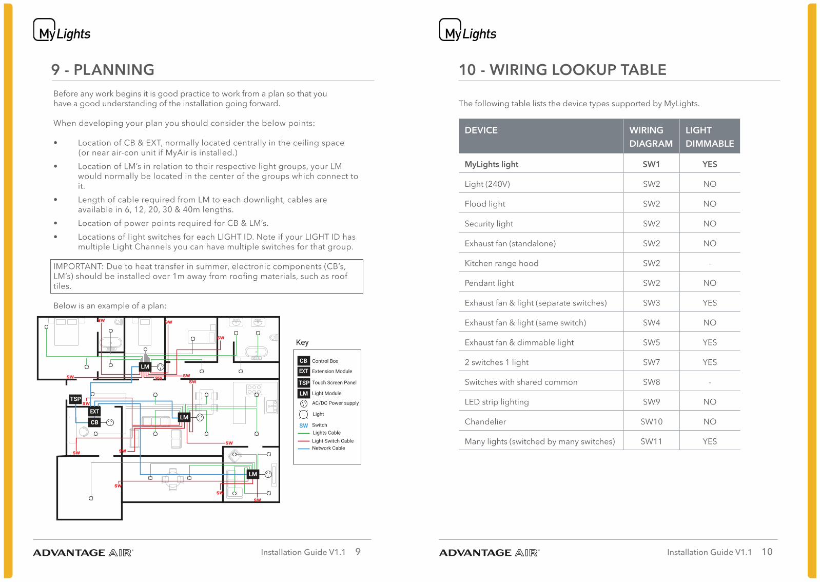
Before any work begins it is good practice to work from a plan so that you have a good understanding of the installation going forward.
When developing your plan you should consider the below points:
• Location of CB & EXT, normally located centrally in the ceiling space (or near air-con unit if MyAir is installed.)
• Location of LM’s in relation to their respective light groups, your LM would normally be located in the center of the groups which connect to it.
• Length of cable required from LM to each downlight, cables are available in 6, 12, 20, 30 & 40m lengths.
• Location of power points required for CB & LM’s.• Locations of light switches for each LIGHT ID. Note if your LIGHT ID has
multiple Light Channels you can have multiple switches for that group.
IMPORTANT: Due to heat transfer in summer, electronic components (CB’s, LM’s) should be installed over 1m away from roofing materials, such as roof tiles.
Below is an example of a plan:
10 - WIRING LOOKUP TABLE
The following table lists the device types supported by MyLights.
DEVICE WIRING DIAGRAM
LIGHT DIMMABLE
MyLights light SW1 YES
Light (240V) SW2 NO
Flood light SW2 NO
Security light SW2 NO
Exhaust fan (standalone) SW2 NO
Kitchen range hood SW2 -
Pendant light SW2 NO
Exhaust fan & light (separate switches) SW3 YES
Exhaust fan & light (same switch) SW4 NO
Exhaust fan & dimmable light SW5 YES
2 switches 1 light SW7 YES
Switches with shared common SW8 -
LED strip lighting SW9 NO
Chandelier SW10 NO
Many lights (switched by many switches) SW11 YES
Installation Guide V1.1 11 Installation Guide V1.1 12
11 - WIRING: SW1
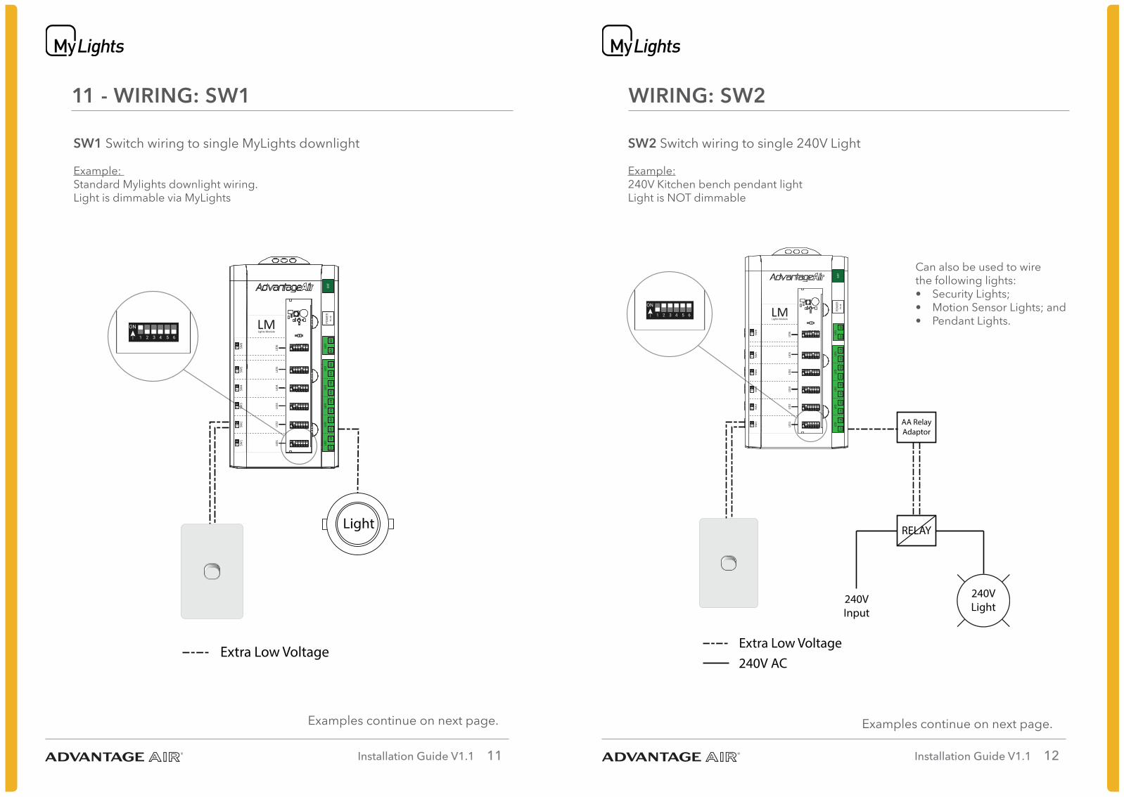
SW1 Switch wiring to single MyLights downlight
Example: Standard Mylights downlight wiring.Light is dimmable via MyLights
Examples continue on next page.
Switch wiring to single MyLights downlight
Extra Low Voltage
SW1
Light
Example: Standard Mylights downlight wiring.Light is dimmable via MyLights
5 61 432
ON
5 61 432
ON5 61 432
ON
5 61 432
ON
5 61 432
ON
LID1
LID2
LID3
LID4
LID5
LID6
LMLights Module
SW6
SW5
SW4
SW3
SW2
SW1
SC
SC
SC
SC
SC
SC
1A1B
2A2B
3A3B
4A4B
5A5B
6A6B
LED
LED
LED
LED
LED
LED
POW
ERPS
-48
EXT
5 61 432
ON
WIRING: SW2
SW2 Switch wiring to single 240V Light
Example: 240V Kitchen bench pendant lightLight is NOT dimmable
Examples continue on next page.
Switch wiring to single 240V Light
Example: 240V Kitchen bench pendent lightLight is NOT dimmable
AA RelayAdaptor
RELAY
240VLight
240VInput
Extra Low Voltage240V AC
SW2
5 61 432
ON
5 61 432
ON
5 61 432
ON
5 61 432
ON
5 61 432
ON
LID1
LID2
LID3
LID4
LID5
LID6
LMLights Module
SW6
SW5
SW4
SW3
SW2
SW1
SC
SC
SC
SC
SC
SC
1A1B
2A2B
3A3B
4A4B
5A5B
6A6B
LED
LED
LED
LED
LED
LED
POW
ERPS
-48
EXT
5 61 432
ON
Can also be used to wirethe following lights:• Security Lights;• Motion Sensor Lights; and• Pendant Lights.
Installation Guide V1.1 13 Installation Guide V1.1 14
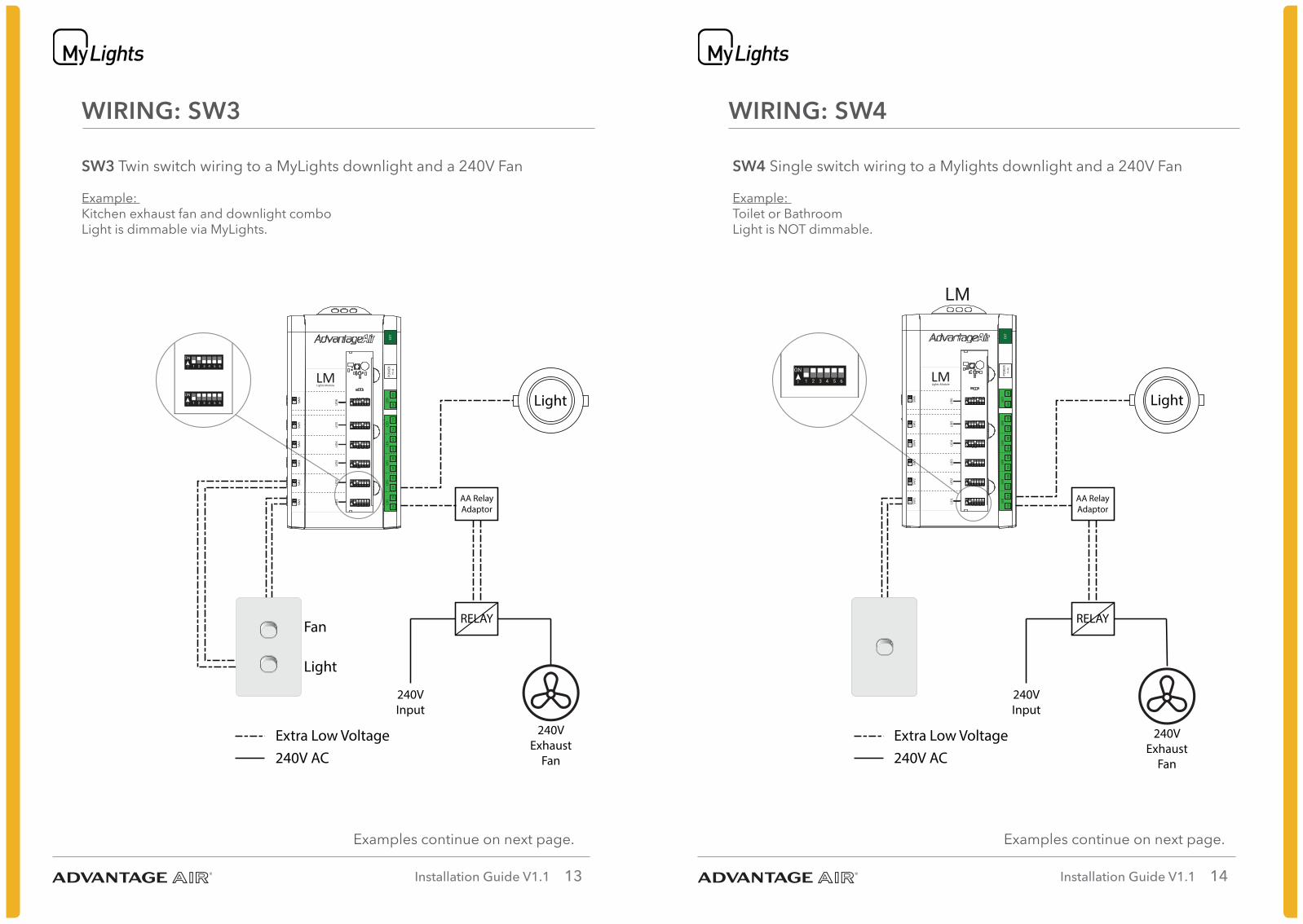
WIRING: SW3
SW3 Twin switch wiring to a MyLights downlight and a 240V Fan
Example: Kitchen exhaust fan and downlight comboLight is dimmable via MyLights.
Examples continue on next page.
Twin switch wiring to an MyLights downlight and a 240V Fan
AA RelayAdaptor
RELAY
240VInput
Extra Low Voltage240V AC
Fan
Light
Light
Example: Kitchen exhaust fan and downlight comboLight is dimmable via MyLights.
240VExhaust
Fan
SW3
5 61 432
ON
5 61 432
ON
5 61 432
ON
5 61 432
ON
5 61 432
ON
LID1
LID2
LID3
LID4
LID5
LID6
LMLights Module
SW6
SW5
SW4
SW3
SW2
SW1
SC
SC
SC
SC
SC
SC
1A1B
2A2B
3A3B
4A4B
5A5B
6A6B
LED
LED
LED
LED
LED
LED
POW
ERPS
-48
EXT
5 61 432
ON
WIRING: SW4
SW4 Single switch wiring to a Mylights downlight and a 240V Fan
Example: Toilet or BathroomLight is NOT dimmable.
Examples continue on next page.
Single switch wiring to an Mylights downlight and a 240V Fan
AA RelayAdaptor
RELAY
240VInput
Extra Low Voltage240V AC
Light
240VExhaust
Fan
Example: Toilet or BathroomLight is NOT dimmable.
SW4
5 61 432
ON5 61 432
ON
5 61 432ON
5 61 432
ON
5 61 432
ON
LID1
LID2
LID3
LID4
LID5
LID6
LMLights Module
SW6
SW5
SW4
SW3
SW2
SW1
SC
SC
SC
SC
SC
SC
1A1B
2A2B
3A3B
4A4B
5A5B
6A6B
LED
LED
LED
LED
LED
LED
POW
ERPS
-48
EXT
5 61 432
ON
Installation Guide V1.1 15 Installation Guide V1.1 16
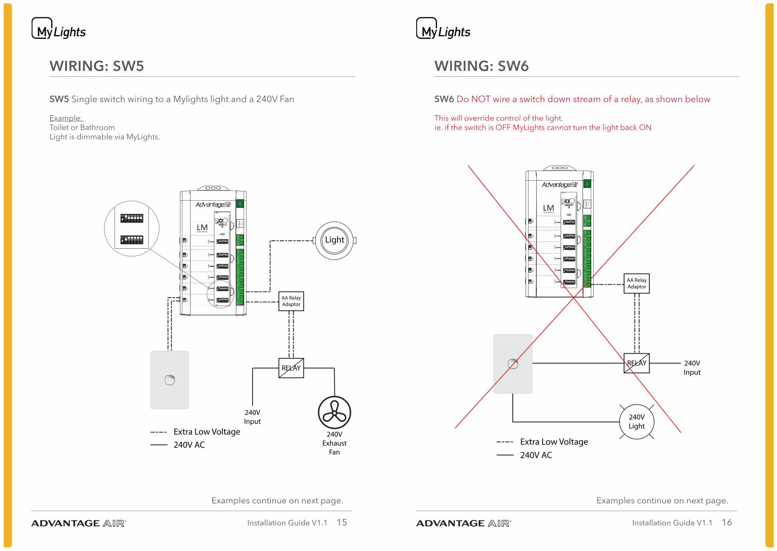
WIRING: SW5
SW5 Single switch wiring to a Mylights light and a 240V Fan
Example: Toilet or BathroomLight is dimmable via MyLights.
Examples continue on next page.
Single switch wiring to an MyLights light and a 240V Fan
AA RelayAdaptor
RELAY
240VInput
Extra Low Voltage240V AC
Light
240VExhaust
Fan
Example: Toilet or BathroomLight is dimmable via MyLights.
SW5
5 61 432
ON
5 61 432
ON
5 61 432
ON
5 61 432
ON
5 61 432
ON
LID1
LID2
LID3
LID4
LID5
LID6
LMLights Module
SW6
SW5
SW4
SW3
SW2
SW1
SC
SC
SC
SC
SC
SC
1A1B
2A2B
3A3B
4A4B
5A5B
6A6B
LED
LED
LED
LED
LED
LED
POW
ERPS
-48
EXT
5 61 432
ON
WIRING: SW6
SW6 Do NOT wire a switch down stream of a relay, as shown below
This will override control of the light.ie. if the switch is OFF MyLights cannot turn the light back ON
Examples continue on next page.
Do NOT wire a switch down stream of a relay, as shown below
This will overide control of the light.ie. if the switch is OFF MyLights cannot turn the light back ON
Extra Low Voltage
AA RelayAdaptor
RELAY
240VLight
240VInput
240V AC
SW6
5 61 432
ON
5 61 432
ON
5 61 432
ON
5 61 432
ON
5 61 432
ON
LID1
LID2
LID3
LID4
LID5
LID6
LMLights Module
SW6
SW5
SW4
SW3
SW2
SW1
SC
SC
SC
SC
SC
SC
1A1B
2A2B
3A3B
4A4B
5A5B
6A6B
LED
LED
LED
LED
LED
LED
POW
ERPS
-48
EXT
5 61 432
ON
Installation Guide V1.1 17 Installation Guide V1.1 18
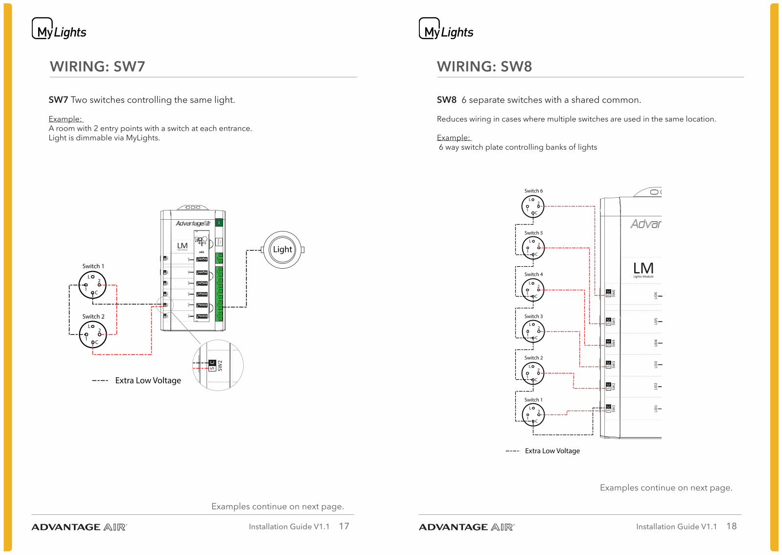
WIRING: SW7
SW7 Two switches controlling the same light.
Example: A room with 2 entry points with a switch at each entrance. Light is dimmable via MyLights.
Examples continue on next page.
Extra Low Voltage
5 61 432
ON
5 61 432
ON
5 61 432
ON
5 61 432
ON
5 61 432
ON
LID1
LID2
LID3
LID4
LID5
LID6
LMLights Module
SW6
SW5
SW4
SW3
SW2
SW1
SC
SC
SC
SC
SC
SC
1A1B
2A2B
3A3B
4A4B
5A5B
6A6B
LED
LED
LED
LED
LED
LED
POW
ERPS
-48
EXT
5 61 432
ON
Two switches controlling the same light.
Example: A room with 2 entry points with a swtich at each entrance. Light is dimmable via MyLights.
SW7
Switch 1
1
2
C
L
Switch 2
1
2
C
L
5 61 432
ON
5 61 432
ON
5 61 432
ON
5 61 432
ON
5 61 432
ON
LID1
LID2
LID3
LID4
LID5
LID6
LMLights Module
SW6
SW5
SW4
SW3
SW2
SW1
SC
SC
SC
SC
SC
SC
5 61 432
ON
Light
WIRING: SW8
SW8 6 separate switches with a shared common.
Reduces wiring in cases where multiple switches are used in the same location.
Example: 6 way switch plate controlling banks of lights
Examples continue on next page.
6 seperate switches with a shared common.
Reduces wiring in cases where multiple switches areused in the same location.Example: 4 way switch controlling banks of lights
SW7
1A1B
2A2B
3A3B
4A4B
5A5B
6A6B
LED
LED
LED
LED
LED
LED
POW
ERPS
-48
EXT
Extra Low Voltage
Switch 2
1
2
C
L
Switch 1
1
2
C
L
Switch 4
1
2
C
L
Switch 3
1
2
C
L
Switch 6
1
2
C
L
Switch 5
1
2
C
L
5 61 432
ON
5 61 432
ON
5 61 432
ON
5 61 432
ON
5 61 432
ON
LID1
LID2
LID3
LID4
LID5
LID6
LMLights Module
SW6
SW5
SW4
SW3
SW2
SW1
SC
SC
SC
SC
SC
SC
5 61 432
ON
Installation Guide V1.1 19 Installation Guide V1.1 20
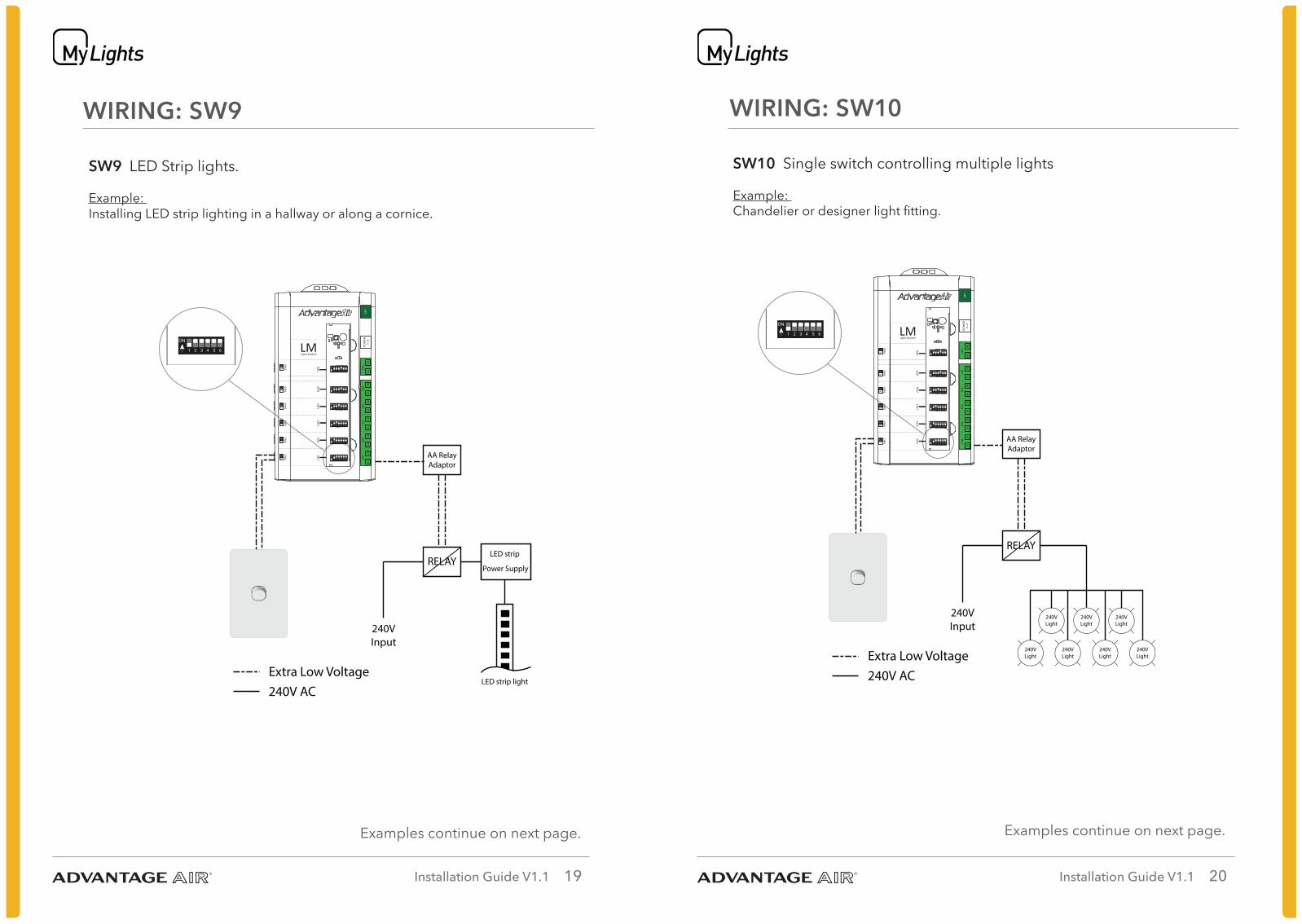
WIRING: SW9
SW9 LED Strip lights.
Example: Installing LED strip lighting in a hallway or along a cornice.
Examples continue on next page.
AA RelayAdaptor
LED strip
LED strip light
Power SupplyRELAY
240VInput
Extra Low Voltage240V AC
5 61 432
ON
5 61 432
ON
5 61 432
ON
5 61 432
ON
5 61 432
ON
LID1
LID2
LID3
LID4
LID5
LID6
LMLights Module
SW6
SW5
SW4
SW3
SW2
SW1
SC
SC
SC
SC
SC
SC
1A1B
2A2B
3A3B
4A4B
5A5B
6A6B
LED
LED
LED
LED
LED
LED
POW
ERPS
-48
EXT
5 61 432
ON
1A1B
2A2B
3A3B
4A4B
5A5B
6A6B
LED
LED
LED
LED
LED
LED
POW
ERPS
-48
EXT
WIRING: SW10
SW10 Single switch controlling multiple lights
Example: Chandelier or designer light fitting.
Examples continue on next page.
AA RelayAdaptor
RELAY
240VLight
240VLight
240VLight
240VLight
240VLight
240VLight
240VLight
240VInput
Extra Low Voltage240V AC
5 61 432
ON
5 61 432
ON
5 61 432
ON
5 61 432
ON
5 61 432
ON
LID1
LID2
LID3
LID4
LID5
LID6
LMLights Module
SW6
SW5
SW4
SW3
SW2
SW1
SC
SC
SC
SC
SC
SC
1A1B
2A2B
3A3B
4A4B
5A5B
6A6B
LED
LED
LED
LED
LED
LED
POW
ERPS
-48
EXT
5 61 432
ON
Installation Guide V1.1 21 Installation Guide V1.1 22
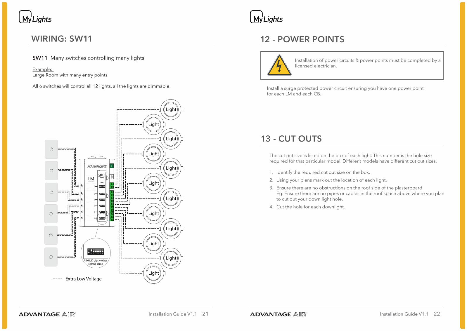
WIRING: SW11
SW11 Many switches controlling many lights
Example: Large Room with many entry points
All 6 switches will control all 12 lights, all the lights are dimmable.
Extra Low Voltage
5 61 432
ON
5 61 432
ON
5 61 432
ON
5 61 432
ON
5 61 432
ON
LID1
LID2
LID3
LID4
LID5
LID6
LMLights Module
SW6
SW5
SW4
SW3
SW2
SW1
SC
SC
SC
SC
SC
SC
1A1B
2A2B
3A3B
4A4B
5A5B
6A6B
LED
LED
LED
LED
LED
LED
POW
ERPS
-48
EXT
5 61 432
ON
Light
Light
Light
Light
Light
Light
Light
Light
Light
Light
Light
Light
All 6 LID dipswitchesset the same
12 - POWER POINTS
Installation of power circuits & power points must be completed by a licensed electrician.
Install a surge protected power circuit ensuring you have one power point for each LM and each CB.
13 - CUT OUTS
The cut out size is listed on the box of each light. This number is the hole size required for that particular model. Different models have different cut out sizes.
1. Identify the required cut out size on the box.2. Using your plans mark out the location of each light.3. Ensure there are no obstructions on the roof side of the plasterboard
Eg. Ensure there are no pipes or cables in the roof space above where you plan to cut out your down light hole.
4. Cut the hole for each downlight.
Installation Guide V1.1 23 Installation Guide V1.1 24
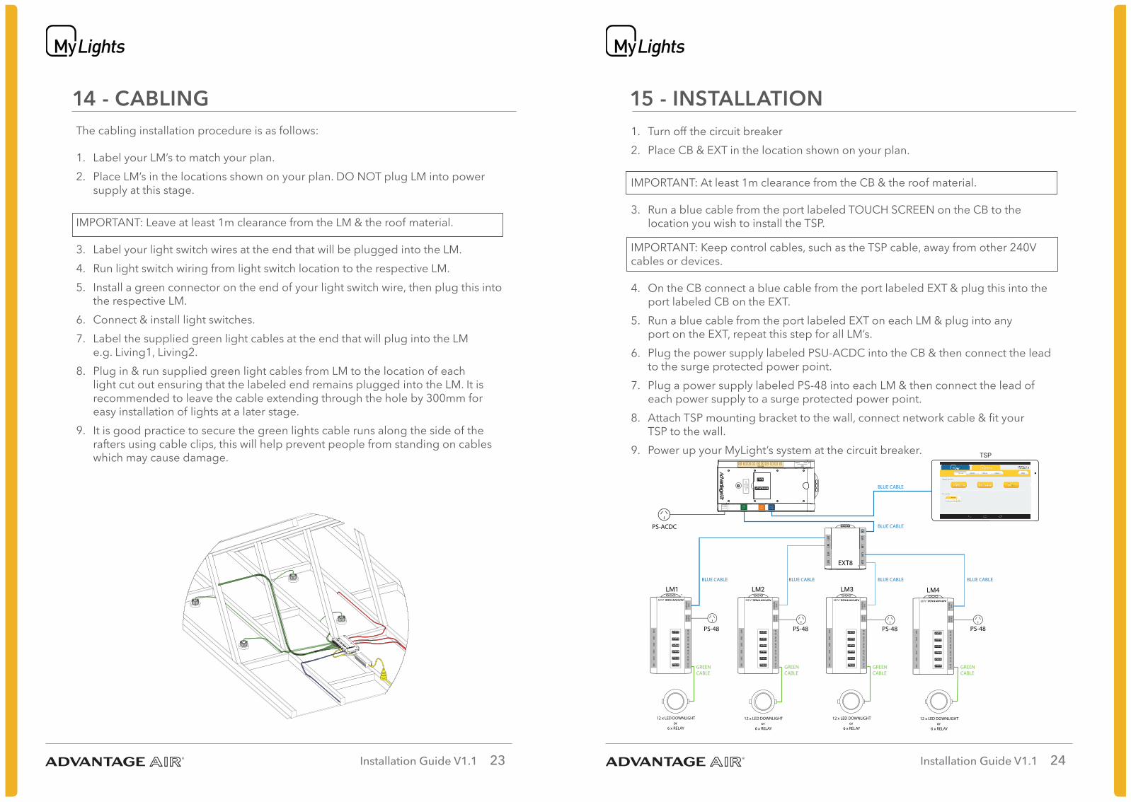
14 - CABLINGThe cabling installation procedure is as follows:
1. Label your LM’s to match your plan.2. Place LM’s in the locations shown on your plan. DO NOT plug LM into power
supply at this stage. IMPORTANT: Leave at least 1m clearance from the LM & the roof material.
3. Label your light switch wires at the end that will be plugged into the LM.4. Run light switch wiring from light switch location to the respective LM.5. Install a green connector on the end of your light switch wire, then plug this into
the respective LM.6. Connect & install light switches.7. Label the supplied green light cables at the end that will plug into the LM
e.g. Living1, Living2.8. Plug in & run supplied green light cables from LM to the location of each
light cut out ensuring that the labeled end remains plugged into the LM. It is recommended to leave the cable extending through the hole by 300mm for easy installation of lights at a later stage.
9. It is good practice to secure the green lights cable runs along the side of the rafters using cable clips, this will help prevent people from standing on cables which may cause damage.
15 - INSTALLATION
-
Scenes SetUpGroupsFavourites Help
Master
FavouritesMaster
All On All Off
Entry
WIR
All On All Off
Ensuite
All On All Off
Hall Way
All On All Off
Rocco Jade Bathroom
Guest Kitchen Dining Living
PS-48
BLUE CABLE
GREENCABLE
GREENCABLE
GREENCABLE
GREENCABLE
BLUE CABLE BLUE CABLE
BLUE CABLE
BLUE CABLE
BLUE CABLE
PS-48
PS-ACDC
PS-48 PS-48
12 x LED DOWNLIGHTor
6 x RELAY
12 x LED DOWNLIGHTor
6 x RELAY
12 x LED DOWNLIGHTor
6 x RELAY
12 x LED DOWNLIGHTor
6 x RELAY
EXT8
CB
EXT8DICT
TOUCH SCREEN
POWERPSU-ACDC
EXTMY+
OTHER
123
4
56
7
8
910 CM / SAM
MOTORS LINK
1. Turn off the circuit breaker2. Place CB & EXT in the location shown on your plan. IMPORTANT: At least 1m clearance from the CB & the roof material.
3. Run a blue cable from the port labeled TOUCH SCREEN on the CB to the location you wish to install the TSP.
IMPORTANT: Keep control cables, such as the TSP cable, away from other 240V cables or devices.
4. On the CB connect a blue cable from the port labeled EXT & plug this into the port labeled CB on the EXT.
5. Run a blue cable from the port labeled EXT on each LM & plug into any port on the EXT, repeat this step for all LM’s.
6. Plug the power supply labeled PSU-ACDC into the CB & then connect the lead to the surge protected power point.
7. Plug a power supply labeled PS-48 into each LM & then connect the lead of each power supply to a surge protected power point.
8. Attach TSP mounting bracket to the wall, connect network cable & fit your TSP to the wall.
9. Power up your MyLight’s system at the circuit breaker.
Installation Guide V1.1 25 Installation Guide V1.1 26
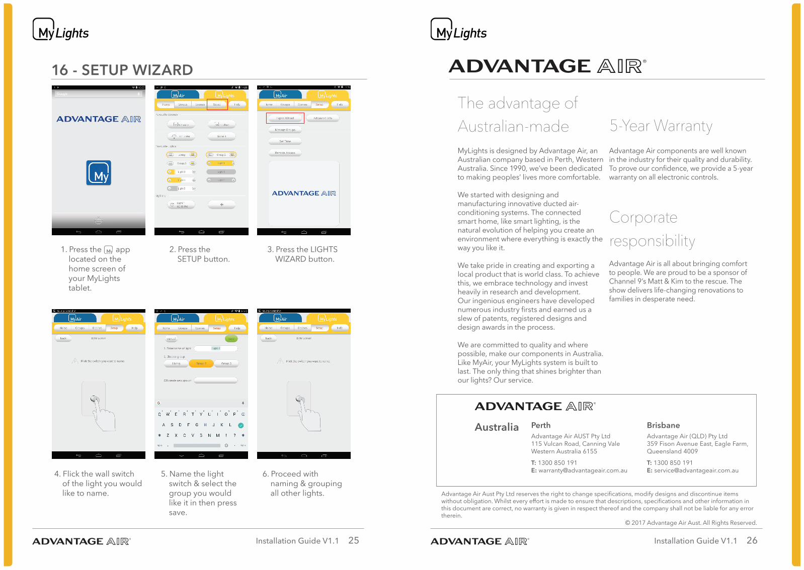
16 - SETUP WIZARD
1. Press the app located on the home screen of your MyLights tablet.
4. Flick the wall switch of the light you would like to name.
2. Press the SETUP button.
5. Name the light switch & select the group you would like it in then press save.
3. Press the LIGHTS WIZARD button.
6. Proceed with naming & grouping all other lights.
The advantage of Australian-madeMyLights is designed by Advantage Air, an Australian company based in Perth, Western Australia. Since 1990, we’ve been dedicated to making peoples’ lives more comfortable.
We started with designing and manufacturing innovative ducted air-conditioning systems. The connected smart home, like smart lighting, is the natural evolution of helping you create an environment where everything is exactly the way you like it.
We take pride in creating and exporting a local product that is world class. To achieve this, we embrace technology and invest heavily in research and development. Our ingenious engineers have developed numerous industry firsts and earned us a slew of patents, registered designs and design awards in the process.
We are committed to quality and where possible, make our components in Australia. Like MyAir, your MyLights system is built to last. The only thing that shines brighter than our lights? Our service.
5-Year WarrantyAdvantage Air components are well known in the industry for their quality and durability. To prove our confidence, we provide a 5-year warranty on all electronic controls.
Corporate responsibilityAdvantage Air is all about bringing comfort to people. We are proud to be a sponsor of Channel 9’s Matt & Kim to the rescue. The show delivers life-changing renovations to families in desperate need.
Australia Perth Advantage Air AUST Pty Ltd 115 Vulcan Road, Canning ValeWestern Australia 6155
T: 1300 850 191 E: [email protected]
Brisbane Advantage Air (QLD) Pty Ltd 359 Fison Avenue East, Eagle Farm, Queensland 4009
T: 1300 850 191 E: [email protected]
Advantage Air Aust Pty Ltd reserves the right to change specifications, modify designs and discontinue items without obligation. Whilst every effort is made to ensure that descriptions, specifications and other information in this document are correct, no warranty is given in respect thereof and the company shall not be liable for any error therein.
© 2017 Advantage Air Aust. All Rights Reserved.